Printable Version of Topic
Click here to view this topic in its original format
914World.com _ 914World Garage _ Powered washer fluid assembly
Posted by: swood Nov 29 2009, 07:40 PM
Ok, so I'm mocking up what I have for this assembly and referencing Andy's http://www.914world.com/bbs2/index.php?showtopic=13261
I have a few questions and I'll post a few pics.
First, when I pulled out the filler tube, it basically crumbled on me. All I have at the moment are zip ties, but here's my modification. I suppose by the time I power it up, if it leaks I can get a better hose clamp. By bypassing the spare tire connection, I can run this tubing right to the pump itself.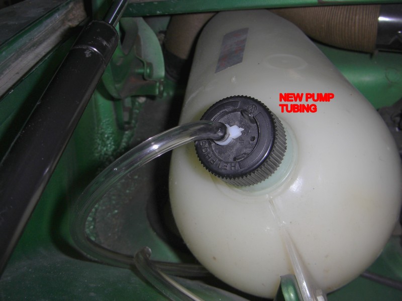
Can I mount my pump in this area?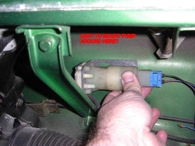
I have a new Bosch relay p/n # 0 332 019 150-010. It looks like it would go here. No clue on how to wire to it yet.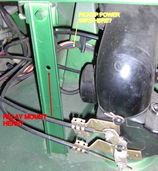
Posted by: swood Nov 29 2009, 07:41 PM
Lastly, the steering column switch. Again looking for assistance on making the wired connection.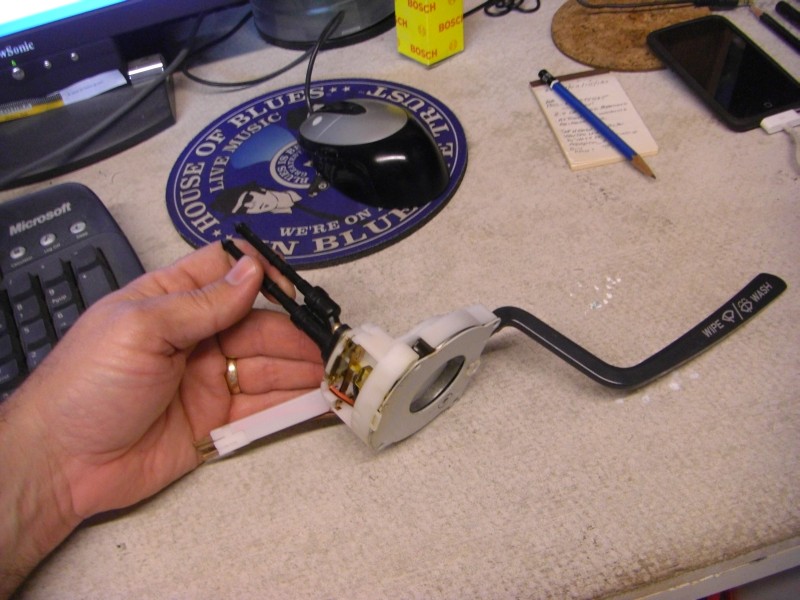
Thanks. And yes, I'm breaking out the wiring diagrams to reference. And this is a '75 model.
Thanks.
Posted by: r_towle Nov 29 2009, 07:45 PM
924 uses the correct switch for the column.
Pump vibrates...mount is on rubber standoffs.
Pump must be below fluid or it does not work well.
Drill hole in lid to keep it from becoming a vacuum inside...
I ran my own new wires...
RIch
Posted by: bobhasissues Nov 29 2009, 08:41 PM
I'm looking at the first picture of your resevoir, are you expecting the washer fluid will be sucked out the top of the resevoir by the pump? If this is the plan, don't count on it working. Your fluid supply has to come from the bottom of the resevoir. Also, you can fabricate your own electric switch for a few bucks using the stock switch stalk and a micro switch avilable from Radio Shack. Save a lot of money and do a search on the topic. "Spoke" had a really nice set-up and posted some photos to a thread I started on the topic several months ago. I fabbed up a homemade switch but after seeing Spoke's, I fabbed up one similar to his.
Posted by: flipb Nov 29 2009, 08:54 PM
Has anyone ever stuck with the stock setup but added something other than the spare tire to pressurize the tank? I don't know what... weak electric air pump? CO2 canister?
I guess that wouldn't eliminate (heck, would probably increase) the chances of douching yourself when you pull the stalk. But somehow seems a little more true to the original engineering.
Posted by: Kirmizi Nov 29 2009, 09:01 PM
Stevo, I did this modification on my '75.
I mounted the pump beneath the fluid reservoir (as per Andy's write up I believe).
As for the relay, mine was already installed (yes, where you indicated) and IIRC it was for intermittent wipers. I also removed the plastic valve behind the wiper switch where the hoses connected, figured that I didn't need that anymore.
Mike
Posted by: kconway Nov 29 2009, 09:11 PM
My car has this mod. The pump is mounted right were your thinking of locating the relay. Works great.
Posted by: 516randy Nov 29 2009, 09:13 PM
I believe the rare factory install of the washer pump is under the washer fluid tank. I think their is also a factory wire that goes from the the wiper control to the pump. There are also some good tech articles on this, maybe here and at pelican.
Good luck
Randy
Let me know how it goes, I was thinking of doing it as well, don't know why though, I never take it out in the rain.
Posted by: swood Nov 29 2009, 09:30 PM
I was thinking that if the pump went under the tank, it could get close to interfering with the gas tank. Will need to bust that out and see what works best.
I might want to come check out your setup Kev.
Posted by: davep Nov 30 2009, 12:43 PM
http://www.914world.com/bbs2/index.php?showtopic=67916
http://www.914world.com/bbs2/index.php?showtopic=81256
My system replaces the water valve with a 5 amp switch, fits all years and includes a vented cover for the tank cap.
Posted by: SirAndy Nov 30 2009, 01:13 PM

I mounted the pump beneath the fluid reservoir (as per Andy's write up I believe).
As for the relay, mine was already installed (yes, where you indicated) and IIRC it was for intermittent wipers. I also removed the plastic valve behind the wiper switch where the hoses connected, figured that I didn't need that anymore.
Yes on all 3 ...

- The stock (/6) location of the pump is below the reservoir and clears the tank just fine.
- The relay is for the intermittent wiper option.
- The water connections on the stalk are not needed anymore.
The pump should be mounted on rubber to reduce noise.
The pump inlet must come from the bottom of the bottle.
You will need to drill a hole in the top cap (or somehow remove the check valve), otherwise the pump will have to suck against a vacuum.
Later model 914 stalks ('73+?) can easily be used to power the pump, no need for a 944 setup.
I'm running the pump directly off the stalk, but eventually will go to a setup with a separate relay and fuse.
 Andy
Andyhttp://www.914world.com/bbs2/index.php?showtopic=13261
Posted by: zonedoubt Nov 30 2009, 03:42 PM
I recommend using some inline check valves at each of the spray nozzles. This way the pump doesn't have to suck fluid through empty tubing every time you operate the stalk. The factory schematics show at least on of these in use, but I haven't seen it mentioned anywhere else. PP has them in stock in their 911 section. Funny thing is the part number starts with "914-". Works well on my electric washer conversion.
Posted by: swood Nov 30 2009, 10:12 PM
Ok, i see my first error. There won't be any new tube connected to the top opening of the water tank, only from the bottom to the intake portion of the pump. The cap needs a hole drilled for air intake. Output side of pump goes to the nozzles. Simple as that. So is does the cap have a check valve that closes the port when there is no tube connected to it (the one connected to the spare tire)?
And thanks for the link to Spokes post Dave...I knew about that one but couldn't find it.
Now, on to the switch and wiring...
Posted by: swood Nov 30 2009, 11:01 PM
So do I need to locate the wire that gets connected to this pink wire with black stripe and connect the pump power side to it? And then ground the other pump wire?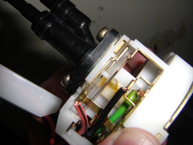
Posted by: Spoke Dec 1 2009, 10:47 AM
I'm not familiar with the pink/black wire. Maybe it runs the wipers when you pull the washer stalk? The water switch is the black appendage shown in the top of the pic. This is where people mount a microswitch or the 944 switch.
Posted by: detoxcowboy Dec 1 2009, 11:14 AM
I suggest you read the pelican parts tech article on this.. yes the pink/black stripe wire is your pump positive side.. (up to you if you want to run a relay or directly to pump) also if the switch is a 924 porsche also same part no. known for use in vw busses and karman ghia's thiugh you will pay twice as much for the porsche... then you need to take the all of the wires out of the 914 white plasitc harness and use your 914 white plastic harness whihc has one less double side on your new switch..,MAKE SURE YOU PUT THEM IN THE CORRECT ORDER AS THEY WERE and run the pink black wire out seperatly inside your column. the 924 switches plastic harness is one wire thicker for holding that pink black wire than the 914 original harness and will not fit in through the column on final installment with the turn signal harness, i suggest you check the fitment of that switch along with your turnsignal switch to see what i am talking about (it is mentioned in pelican and aa tech article) plus i just re-did mine using same, and i left the plastic orginal valves in there for prostertity... the ground wire from your pump can ground right next to where you place it. using rubber mount stops the dental drill noise when operating the factory rubber mounts s require drilling hole so choose a mount below the tank where you can drill or do it from underneath the passeneger foot well . also THE PUMP HAS TO BE PRIMED BEFORE IT WORKS OR WHEN FOR WHATEVER REASON RUNS DRY so you want the pump below the tank so the flow is "wet" continually. Also the switch must be fully installed into your column so it grounds to it or your delays will be on constantly in stalk position lower and neutral. Basically it is way easier than it sounds..
Posted by: davep Dec 1 2009, 01:52 PM
I'm not familiar with the pink/black wire. Maybe it runs the wipers when you pull the washer stalk?
Intermittent wiper function. Replace the valve with a switch and you can have both.
Posted by: detoxcowboy Dec 1 2009, 02:59 PM
I'm not familiar with the pink/black wire. Maybe it runs the wipers when you pull the washer stalk?
Intermittent wiper function. Replace the valve with a switch and you can have both.
nope thats not it, the pink/black stripe wire is for a washer pump, the brown wire runs the 3 stroke wipe, the delay is from another wire.. I have had a volt meter w/ light on the wires, when the stalk is pulled back the pinkwire/black stripe and the brown wire both get powered when the stalk is puylled back. thus giving you liquid on your wqindshield from the pump and the 3 stroke to wipe it off simutainuosly.
you do not need to replace the valve with any switch (the "switch" is to your washer pump from the pink black wire whihc gets electrical contact from the same switch that makles the mechanical valve switch work.. .. nor do you need to remove it for any other reason than having difficulties mounting the switch in column i left mine on and no worries.
you could reverse the brown wire and the pink black stripe wires but one of each still needs to go to their location (1 to the wiper harness and the other to the pump)
how many wires are in the switch pictured vs. the one that came with your 914 from the factory? you will see there is 1 extra wire now the pink black stripe one. probably to save money making the same switch with different layouts they now made on with different options.. they could sell them better and have wider need for the same swtich. so use the black plastic valve or use the wire.. put it ina newer porsche or put it in an old bus..
Posted by: McMark Dec 1 2009, 05:49 PM
Here's the stock 914/6 washer pump mounting holes. I can get more accurate measurements if you want to go this route.
Attached image(s)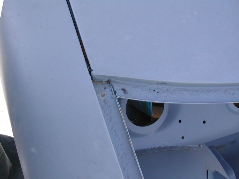
Posted by: FlacaProductions Jan 26 2020, 12:48 PM
Hi All - I'm really sorry to dredge this up again but it's juuuuust not 100% clear to me (or maybe it is....) as - as I've said before - unfortunately I'm away from the car and try to do reading/research without being able to actually consult my 914 in the flesh.
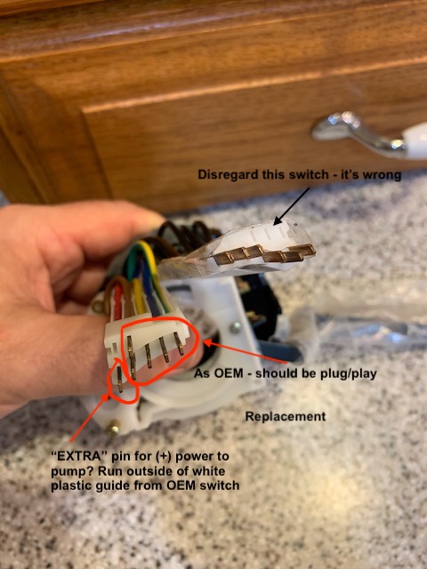
Old wiper switch comes out, white plastic "tray" is transplanted to new switch, placing the 5 wires and pins in corresponding positions. "Extra" or 6th wire is run outside of the "tray" and is connected to provide (+) power to washer pump.
Disregard the turn signal depicted in the replacement pic - it's incorrect. I have the proper switch ready to go.
So...I believe this is correct - right?
(one of the things that makes this a bit confusing is the fact that the replacement switch wiring colors are different from OEM - so when transferring to the "tray" one just needs to make sure that the positions are retained)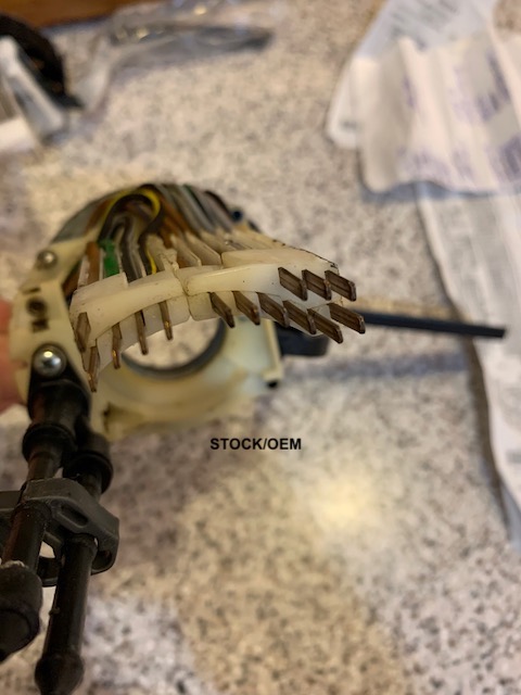
Posted by: 914Sixer Jan 26 2020, 03:33 PM
You will have to match the wire location of the aftermarket switch to old factory switch and write down the wire colors to know how wires lay in old tray.
You have to use the old 5 pin tray 7pin is too thick to go in 72-74 housing. Not sure if 7 pin will fit later 75-76.
Posted by: FlacaProductions Jan 26 2020, 03:58 PM
Yep. I agree. I think I finally have this correct in my head.
Posted by: barefoot Jan 26 2020, 09:42 PM
Lastly, the steering column switch. Again looking for assistance on making the wired connection.
Thanks. And yes, I'm breaking out the wiring diagrams to reference. And this is a '75 model.
Thanks.
There's a replacement for your pneumatic "switch" which converts to an electric switch to power your washer pump. I haven't installed mine yet as i had previously wired a momentary push switch in the dash.
If interested I can find the vendor for you.
Barefoot
Posted by: FlacaProductions Jan 26 2020, 09:46 PM
Thanks @http://www.914world.com/bbs2/index.php?showuser=15673 - I have that switch as well but since I was replacing the whole thing I thought I’d try to go w stock wiring. I am just trying to not have to do it twice.
Posted by: RickS Jan 26 2020, 10:07 PM
Wow, rather than dealing with mounting the stalk switch and the wiring issues, I just installed a Radio Shack push on spring switch with an in-line fuse and was done with it. It looks like it belongs right next to the pull-on switches. Might just be too simple.
The advice here how to do it properly is spot on though.
Posted by: cary Jan 26 2020, 10:27 PM
http://www.914world.com/bbs2/index.php?showtopic=331673
Posted by: FlacaProductions Jan 27 2020, 09:30 AM
I've read all of the threads on this and done a lot of research but I guess my question boils down to: is the "extra" pin (circled) (+) or (-) when the stalk is pulled back?
Posted by: ctc911ctc Jan 28 2020, 01:55 PM
I just changed the wiper selector in my '74 2.0.
Since I was going in there I changed the turn signal selector as well.
I followed the direction in this thread and I too burned a few fuses when I installed the assembly.
My findings:
1. The new wiper selector mounting assembly (round white plastic) has been modified (perhaps for the 924?) and is a mil or two larger in diameter than the original equipment, as a result, it is a much tighter fit into a 914. My source has stated it _was_ for a 924 but was mechanically the same part with the exception of the extra wire.
2. Once it was installed, one of the copper blades is "proud" or "outside of" the plastic mounting piece and as a result grounds itself against the inside of the steering wheel shaft housing.
3. I tried to put tape over the blade but the fitting is so tight, the blade did what blades do and cut through the tape
4. I then thought about removing the blade and then decided to file it back below the edge of the mounting housing so it would NOT rub against the steering wheel shaft housing.
4. It took a few in/out exercises and as a result, the handle is now a bit loose and feels like it has been bent and then loosened internally......sigh.
5. I am buying ANOTHER one since the man-handling was my fault. Will install it and PRIOR I will do the following
A. file back the blade
B. use a micrometer and grind/sand the assemble so it is a better fit internally so the install and the removal is somewhat straightforward.
C. Take pictures and try and write an authoritative procedure using a 924 wiper controller.
Stay tuned!
Posted by: ctc911ctc Jan 29 2020, 05:08 PM
OK, I think I guessed incorrectly.....however, 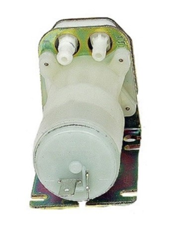
I guessed the pressure side of the pump would be the one with the notch on the nozzle (marked D - Druck?) where the nozzle without the notch would be the one sucking (Marked S - Sauger perhaps? ).
Hooked it up and no squirty fluid. Lot's of noise though! 
Since the markings are so intuitive ( "S" and "D" ??????) perhaps I hooked up incorrectly?
Any experience with this device?
I bought it from a 914 reputable web site.
Note to web dealers - perhaps a little piece of paper decrypting installations for your parts? (installation guides, URLs, piece of paper, schematic, anything.....)
Posted by: FlacaProductions Jan 29 2020, 06:53 PM
that should be correctly plumbed - the one with the barb goes to the nozzles because of the pressure outgoing.
is the tank vented so a vacuum isn't created?
how long did you run it? Is it below the tank?
Posted by: ctc911ctc Jan 29 2020, 08:51 PM
that should be correctly plumbed - the one with the barb goes to the nozzles because of the pressure outgoing.
is the tank vented so a vacuum isn't created?
how long did you run it? Is it below the tank?
Ah - gravity feed????? OK, got it - will correct and report......Darn, had a REAL good spot for it too...................

Posted by: FlacaProductions Jan 29 2020, 08:58 PM
not sure it's exactly gravity fed but i've read where that's the way it needs to be....
Posted by: SirAndy Jan 29 2020, 09:31 PM

You *need* a hole in the filler cap for this to work, otherwise the pump will never get any water out of the bottle.
http://www.914world.com/specs/tech_el_washer.php
Posted by: davep Jan 29 2020, 09:46 PM
So I designed a disc that was 3D printed to fit the cap and provide the venting for my kit, and the mount for a momentary switch to replace the water valve. No need to replace the wiper switch assembly.
Posted by: ctc911ctc Jan 30 2020, 07:19 AM
Yes, I have the filler cap off - biggest hole I could find -
Thank you!
You *need* a hole in the filler cap for this to work, otherwise the pump will never get any water out of the bottle.
http://www.914world.com/specs/tech_el_washer.php
Powered by Invision Power Board (http://www.invisionboard.com)
© Invision Power Services (http://www.invisionpower.com)