Printable Version of Topic
Click here to view this topic in its original format
914World.com _ 914World Garage _ MPS- delving into it's secrets?
Posted by: jk76.914 Jan 30 2010, 11:57 AM
I collected a number of MPS over a couple of years. Most held vacuum, some did not. I measured inductance vs. vacuum on those that I could, but then took all of them apart (except one brand new one).
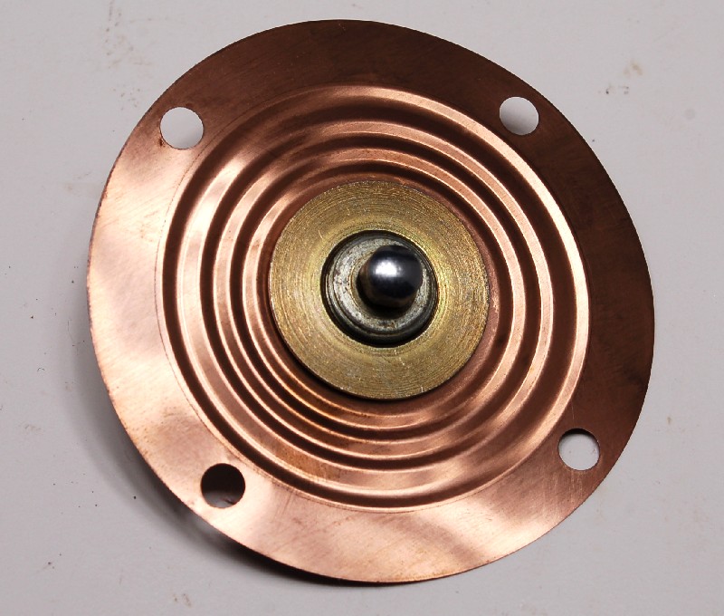
The is a lot of variety in the diaphrams, probably because they get replaced when virtually every MPS is rebuilt. The photo below shows four diaphrams. I'll follow with descriptions and observations...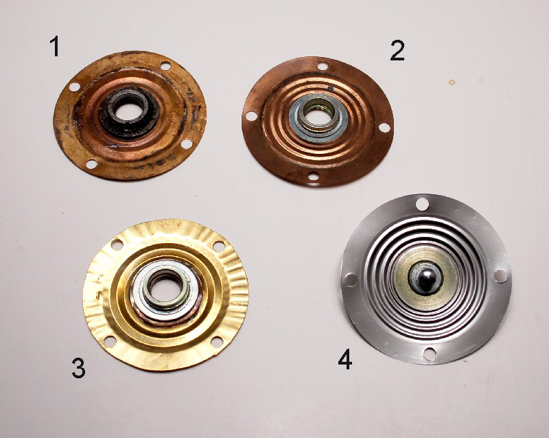
#1- copper, 2 pleats. This came from a rebuilt MPS that was in a pond or river for some time. There was actually sand in it, along with tiny aquatic snail shells of some sort, and the copper was pretty much green. This diaphram was ruptured. The workmanship is very good, and the alloy is idential to stock (see chart below). The threaded bushing looks like stock in design and attachment.
#2- copper, 3 pleats. This is a stock diaphram from a riveted MPS. It is ruptured.
#3- brass, 2 pleats. This is from a rebuilt MPS. I have three of these diaphrams, all similar. This MPS was freshly rebuilt in a rebuilder's box. Looked like new with fresh paint and plastic cap on vacuum port, but it leaked slightly. You can see why when you look at the ripples in that flange. The O.D. looks like it was cut out by hand with tin snips, and the threaded bushing was taken from a stock diaphram and soldered by hand into place. At the bottom in the picture, you can see that the flange is pretty smooth- that's where I tapped it out with a machinist's hammer on an anvil. I have no doubt that the leakage was from around the O.D. of the diaphram, and that tapping it out would probably fix it. This material (brass, see chart below) is stiffer and thicker than any of the rest. It would add quite a bit of spring tension to the mass-spring-damper system. In general, I rate the workmanship on this as "crappy", though maybe you could get a running car out of it.
#4- stainless steel, 3 pleats. This one is a bit of an enigma. It is identical to stock except that it is made from stainless (see chart below). The workmanship is perfect. It is from a rebuilt MPS. Interestingly, it is the MOST COMPLIANT of all of them, while most steel ones are reported to be stiffer. The other part of the enigma- the aneroid cells from this MPS are also stainless- same alloy. My suspicion is that this is a late Bosch rebuilt. Who else would make stainless cells, because the cells don't fail very often, so there are lots of spares available out there, and the cells are pretty complicated to make...
*** EDITED *** Materials. I measured alloy composition at work using an X-Ray Fluorescence analyzer. This machine is very precise, but it has limits to the range of elements that it can detect. Unfortunately, it cannot detect Beryllium (Be), and it is likely that the stock (at least) diaphram contains Be to harden and strengthen it. You can see a couple of things here though- the stainless diaphram and stainless cells are of exactly the same composition- nickel-chromium stainless steel. The nickel explains why they are slightly magnetic, as many stainless alloys are not. ***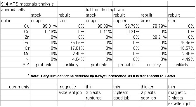
Conclusions (really opinions) - The diaphram was put in there (early VW D-jets did not have one) to provide altitude compensation and to soften transition from leaner (high vacuum) to richer (low vacuum) regions. Early D-Jets had a separate unit with a diaphram and a switch to inform the ECU to richen the mixture at low vacuum. Cost reduction may have been a third reason- eliminating the separate unit, wiring, vacuum hose, etc. Anyway, this switch was either on or off, no soft transition. The MPS had only 2 aneroid cells and no diaphram, and its inductance curve was essentially a straight line from 0" to 25". There was no mixture compensation for altitude with this arrangement.
I'm thinking that the lower the stiffness of the diaphram, the more consistency in the setup and responsiveness, while both of these objectives are met. By maximizing compliance of the diaphram, the springs acting in the system are mainly the coil spring and the leaf springs that act to locate the armature.
My stainless diaphram is the most compliant, but there is another feature of steel (if I remember correctly) that adds to the argument that this is a late Bosch design- steel has a much higher Youngs modulus than copper. The higher the Youngs modulus, the greater the fatigue resistance, and the vastly most common failure mode of the MPS is fatigue failure. Could this have been a Bosch attempt to solve a reliability problem, even as the technology was being superceded by more modern ones? Since the cells are also subject to fatigue, would they have switched them over at the same time?
I am planning on assembling my own personal MPS using the stainless parts, and seeing how close I can tune it to my engine.
There are lots of other parts in the MPS that I've formed opinions about, but I'll hold off for now.
These are my own opinions, which may not be popular, so BLAST AWAY!!
(eye candy below)
Posted by: Bartlett 914 Jan 30 2010, 12:32 PM
Great Job! That is interesting information. If it can be shown than SS will work then maybe this will resolve the availability crisis concerning these MPS units.
Posted by: underthetire Jan 30 2010, 01:20 PM
Good work! It was always assumed it was BeCu, and it is still available, but expensive. Stainless would solve the cost issue for sure. I had sent a MPS to a freind of mine that does stamping, and for the small qty's the price was going to be over 100 bucks each. Everyone but capn balked at the price, but the dies are not free to build.
I just think it's awesome you can check materials that way. It's very cool.
Posted by: jk76.914 Jan 30 2010, 04:14 PM

Good work! It was always assumed it was BeCu, and it is still available, but expensive. Stainless would solve the cost issue for sure. I had sent a MPS to a freind of mine that does stamping, and for the small qty's the price was going to be over 100 bucks each. Everyone but capn balked at the price, but the dies are not free to build.
I just think it's awesome you can check materials that way. It's very cool.
The stainless story is still just a theory- I haven't proven it works as well as, much less better than, the stock. (But I think it will!) In the meantime, if you're looking to repro them, the pure copper may be a good bet. It should form better than the stainless, and it'll be a lot cheaper than BeCu alloy.
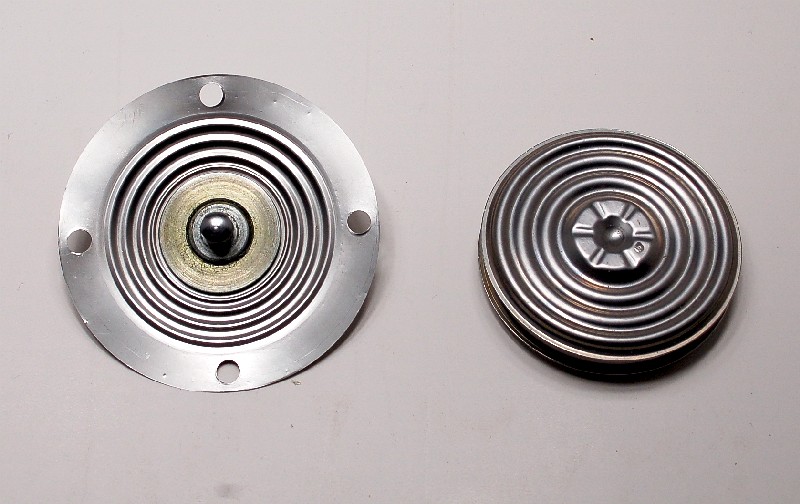
Photo below is my stainless diaphram with its mating stainless cell assembly-
Posted by: detoxcowboy Jan 30 2010, 11:19 PM
"This came from a rebuilt MPS that was in a pond or river for some time. There was actually sand in it, along with tiny aquatic snail shells of some sort,"
THey just took it out and chucked it in the water 
NIce work, great research thanks for sharing..
Posted by: Dave_Darling Jan 31 2010, 01:21 AM
They gave it the "float test"? 
(Must'a thought it was part of a single-Weber setup, perhaps...)
--DD
Posted by: 914Sixer Jan 31 2010, 08:08 AM
Of the MPS I have taken apart, I have only seen version 4 in what looks like solid copper. I know where there are several VW Type 3 MPS that are NOS that I was considering buying them for just the diaphram. I might get one just to take it apart.
Posted by: pbanders Feb 1 2010, 11:11 AM
Wow, really great info! With your permission and credit to you, can I use some of the photos and data on my MPS page (see link in sig)?
You mention the full-load diaphragm provides altitude compensation. This is only true under heavy and full-load conditions. The only MPS's that provided part-load altitude compensation were the 0 280 100 100 series that was used on the MB's. These units lacked the full-load diaphragm (full-load was sensed by the throttle switch) and had an altitude compensation cell that was connected to the atmosphere through a holow screw.
I agree with your observation that the lower the "stiffness", or spring constant of the diaphragm, the less effect it will have on the transition characteristic. For any material used, the thickness and pleat design will vary. Reliability and resistance to fatigue failure is also an important consideration in the material selection.
Crafting the aneroid cells out of a different material and/or a different pleat design would be tricky. The issue here is to identically duplicate the pressure vs. displacement characteristic of the OEM cells. It would interesting to compare the SS cells to the OEM cells for this characteristic.
Positioning of the full-load stop is also critical to defining the transition region, setting the proper full-load mixture, and reducing the mechanical stress on the full-load diaphragm. Bosch sets most MPS to a 2 in. Hg engagement, though I have seen some units set to 4 in. Hg.
Again, great stuff, thanks for sharing it with us.
Posted by: mtndawg Feb 1 2010, 04:31 PM
This information is great.This is what I've often wondered about...If another diaphragm were created, it would have to be made with consideration for temperature, thickness, flexibility, pleat design, etc...Basically all the things you've mentioned. Jim you are on the right track!
Posted by: jk76.914 Feb 1 2010, 08:46 PM
Wow, really great info! With your permission and credit to you, can I use some of the photos and data on my MPS page (see link in sig)?
You mention the full-load diaphragm provides altitude compensation. This is only true under heavy and full-load conditions. The only MPS's that provided part-load altitude compensation were the 0 280 100 100 series that was used on the MB's. These units lacked the full-load diaphragm (full-load was sensed by the throttle switch) and had an altitude compensation cell that was connected to the atmosphere through a holow screw.
I agree with your observation that the lower the "stiffness", or spring constant of the diaphragm, the less effect it will have on the transition characteristic. For any material used, the thickness and pleat design will vary. Reliability and resistance to fatigue failure is also an important consideration in the material selection.
Crafting the aneroid cells out of a different material and/or a different pleat design would be tricky. The issue here is to identically duplicate the pressure vs. displacement characteristic of the OEM cells. It would interesting to compare the SS cells to the OEM cells for this characteristic.
Positioning of the full-load stop is also critical to defining the transition region, setting the proper full-load mixture, and reducing the mechanical stress on the full-load diaphragm. Bosch sets most MPS to a 2 in. Hg engagement, though I have seen some units set to 4 in. Hg.
Again, great stuff, thanks for sharing it with us.
On the data and photos- you're welcome to them, with one caveat. We're using beryllium in a project at work, and one of the characteristics is that it is transparent to X-rays. So I need to verify that our XRF is capable of detecting Be in alloys. If not, those numbers may not be right. I'm travelling until the end of the week, so it'll be Friday before I can get with the lab guy. We have other means of measuring alloys that I can pursue that don't use X-Rays. The brass and stainless alloys should be correct.... Sorry to everyone if my info was premature. I'll be sure to confirm or correct it shortly.
That makes sense about the full load only altitude compensation. The diaphram has to lift off the stop for any compensation to occur.... makes sense. I have a 0 280 100 120 MPS from a Cosworth Vega that is like the MB MPS you described... but then it is, as you said, part of the 100 series... Interesting that Chevrolet licensed the technology directly from Bendix, not Bosch, but all the comonents are Bosch.
I measured several (maybe 6) aneroid cells sets using the same MPS, but with the diaphram locked. I set their inductance to a common value at the same vacuum, and then measured and plotted the curves. Their slopes are identical. I plotted them on the same axis, and they are as coincident as I can imagine. These 6 included a set from a 0 280 100 001 (early type 3, no diaphram, probably the simplest MPS out there) AND the stainless steel set.
So now I'm setting up to measure the vacuum/L curves for diaphrams alone. I sacrificed a set of perfectly good aneroid cells by cutting them open and filling them with gorilla glue to set them. I let them harden in my vise with the jaws set to original cell dimension (gorilla glue expands when it hardens, and would have pushed them open). First thing I found was that the cells ARE MANUFACTURED WITH PARTIAL VACUUM INSIDE!! As soon as my cutoff blade broke through, they expanded out and became flacid. Anyway, now that they're hardened up, I'm going to measure inductance curves, which will represent the response of the diaphrams alone.
I'm thinking that I can combine the diaphram and cell responses using superposition and get pretty close to what the finished MPS should be.... getting interesting.
Posted by: pbanders Feb 2 2010, 09:25 AM
I measured several (maybe 6) aneroid cells sets using the same MPS, but with the diaphram locked. I set their inductance to a common value at the same vacuum, and then measured and plotted the curves. Their slopes are identical. I plotted them on the same axis, and they are as coincident as I can imagine. These 6 included a set from a 0 280 100 001 (early type 3, no diaphram, probably the simplest MPS out there) AND the stainless steel set.
That's good to know that replacements for the cells exist that accurately duplicate the OEM cells response to vacuum.
If you look at the Bosch MPS patent that's referenced at my site, they state that the cells are evacuated - i.e. under vacuum. I assume this was to eliminate issues with the reference pressure.
Posted by: jk76.914 Feb 9 2010, 05:49 AM
I'm back. I looked in to this, and unfortunately, I was right (the second time). XRF cannot measure elements with atomic numbers lower than about 12, and Be is 4. XRF is steadily improving its detection technology, but given that Be is transparent to X-rays, it'll probably never be able to detect it.
How it works (roughly)- an X-ray is beamed onto the sample, which excites the electrons in the atoms, so they move to a higher energy level. When the X-ray is stopped, they move back to their original level, and emit photons (light), at a frequency that is characteristic of the element(s). So if a material is transparent to X-ray, it doesn't get excited.
So I poked around at alternatives. EDX (or EDS) analysis is similar but uses a beam of electrons from a scanning electron microscope to add the energy instead of X-rays. Measurement is then similar. Looks like they can read down to atomic number 5- still not low enough for Be, but still a pretty simple test....
It may be enough to just detect presence of Be, if not the actual amount. That may be enough, since many BeCu alloys I've investigated only have maybe 3% Be, so just knowing its there may be enough to know what we'd be in for trying to reproduce it. Still checking...
So anyway, I want to delete the table in my original post- anyone know how I can go in and edit that post? I'd probably replace it with one that at least still shows the stainless and brass composition...
Sorry about the red herring, guys.
Posted by: ArtechnikA Feb 9 2010, 06:17 AM
...anyone know how I can go in and edit that post?
when you (the OP) view the post you will see, at the bottom-right of the post, a small box with edit options. 'Full' is just like the original composition page, with smileys and formatting widgets and such. 'Quick' is a basic text editor if you're just changing words around. Make your changes and click 'Complete Edit.'
Ta Da.
Posted by: pbanders Feb 9 2010, 08:57 AM
I used to do a lot of surface analysis when I worked in silicon microcontamination in the '80's and '90's. My guess is that there may be some simpler chemical tests you could use instead of surface analysis. I'll ask one of my old colleagues about this and see what he says.
Posted by: pbanders Feb 9 2010, 09:53 AM
I used to do a lot of surface analysis when I worked in silicon microcontamination in the '80's and '90's. My guess is that there may be some simpler chemical tests you could use instead of surface analysis. I'll ask one of my old colleagues about this and see what he says.
I haven't heard back yet, but I did some poking around on the web. I had a dim memory of this earlier that I wasn't sure of, but it tuned out to be correct. If you're going to use surface analysis, you need an Auger Electron Spectroscopy (AES - also known as as SAM scopes) tool, which is sensitive to light elements.
Posted by: pbanders Feb 9 2010, 10:02 AM
Also seems like once we get a material and a design together, we could get a custom metal shop to pump out a run of them. Example:
http://www.peterforg.com/metal-stamping-services.html
Big issue I see with this diaphragm is getting the central threaded flange fabricated and pressed on. I assume this is a two-part assembly that's pressed into place.
Posted by: Bleyseng Feb 9 2010, 10:47 AM
From RustyWa years ago in a PM to me.
"You were correct....COPPER.
--------
Ok, did the marterial analysis on the OEM diaphram this morning using a Niton XL-II 800 handheld alloy analyzer.
I made three different scans of the sample piece I got from Geoff. The readings were as follows:
#1 - 99.78% Cu
#2 - 99.20% Cu
#3 - 99.39% Cu
No berillium. Supposedly anything between 98%-100% copper is considered pure.
The remainder of the 100% reading was a spattering of Al, Si Br, Phos Brz."
The stamping of the copper pleat isn't too hard to setup but as you say the two part center is. I looked at making a stamp with a machinist friend and it wasn't expensive. Coming up with the center part is and blocked my efforts.
My tests on units with steel diaphrams were they aren't as responsive and tend to make the car jerky in real world driving.
Posted by: pbanders Feb 9 2010, 10:53 AM
From RustyWa years ago in a PM to me.
"You were correct....COPPER.
--------
Ok, did the marterial analysis on the OEM diaphram this morning using a Niton XL-II 800 handheld alloy analyzer.
I made three different scans of the sample piece I got from Geoff. The readings were as follows:
#1 - 99.78% Cu
#2 - 99.20% Cu
#3 - 99.39% Cu
No berillium. Supposedly anything between 98%-100% copper is considered pure.
The remainder of the 100% reading was a spattering of Al, Si Br, Phos Brz."
The stamping of the copper pleat isn't too hard to setup but as you say the two part center is. I looked at making a stamp with a machinist friend and it wasn't expensive. Coming up with the center part is and blocked my efforts.
My tests on units with steel diaphrams were they aren't as responsive and tend to make the car jerky in real world driving.
Great info, thanks. Though it's pure Cu, CuBe might be better, as it has much better fatigue resistance. Might not be as flexible, though.
I wonder if the 2-part flange stamping is a common part type?
Posted by: Bleyseng Feb 9 2010, 11:17 AM
From RustyWa years ago in a PM to me.
"You were correct....COPPER.
--------
Ok, did the marterial analysis on the OEM diaphram this morning using a Niton XL-II 800 handheld alloy analyzer.
I made three different scans of the sample piece I got from Geoff. The readings were as follows:
#1 - 99.78% Cu
#2 - 99.20% Cu
#3 - 99.39% Cu
No berillium. Supposedly anything between 98%-100% copper is considered pure.
The remainder of the 100% reading was a spattering of Al, Si Br, Phos Brz."
The stamping of the copper pleat isn't too hard to setup but as you say the two part center is. I looked at making a stamp with a machinist friend and it wasn't expensive. Coming up with the center part is and blocked my efforts.
My tests on units with steel diaphrams were they aren't as responsive and tend to make the car jerky in real world driving.
Great info, thanks. Though it's pure Cu, CuBe might be better, as it has much better fatigue resistance. Might not be as flexible, though.
I wonder if the 2-part flange stamping is a common part type?
I can source Cu-Be sheet from a friend in The Netherlands in fairly small quantities if you want some. For this I would need the alloy percentages.
I can't commit to do anything on MPS's myself now as I am leaving for Suriname for 6 mos next month. I do have a ton (50+) junk MPS's and parts laying around that I would love to have diaphrams for at some point. I'll take a diaphram with me to have a machinist make a stamp in Suriname (cheap).
Posted by: Jeff Bowlsby Feb 9 2010, 02:36 PM
As easy as it would be to make it from pure copper I have a hard time believing it is only coppper. Cu is such a soft metal and it work hardens very quickly.
This from the internet showing how little beryllium is sometimes used in its alloy form:
"The most popular alloys of beryllium at the present time are those with copper metal. Copper-beryllium alloys contain about 2 percent beryllium. They conduct heat and electricity almost as well as pure copper but are stronger, harder, and more resistant to fatigue (wearing out) and corrosion (rusting). These alloys are used in circuit boards, radar, computers, home appliances, aerospace applications, automatic systems in factories, automobiles, aircraft landing systems, oil and gas drilling equipment, and heavy machinery.
and...
Health effects
Beryllium is a very toxic metal. It is especially dangerous in powder form. The effects of inhaling beryllium powder can be acute or chronic. Acute effects are those that occur very quickly as the result of large exposures. Chronic effects are those that occur over very long periods of time as the result of much smaller exposures. Acute effects of inhaling beryllium powder include pneumonia-like symptoms that can result in death in a short time. Chronic effects include diseases of the respiratory system (throat and lungs), such as bronchitis and lung cancer.
Read more: http://www.chemistryexplained.com/elements/A-C/Beryllium.html#ixzz0f4XtvMtO"
I also looked into have the two piece center fitting fabbed at one time. I found the press-fit clamping ring at McMaster Carr, its a stock item. The inner-threaded fixture should not be hard at all for a machist with a lathe, and its may be possible to simply cut off the clamping washer from existing diaphrams with a dremel and reuse them with a new clamping ring - have not tried it though. The two-piece fixture would need to be pressed together, presumably on an arbor press.
And this which shows that some mfrs make BeCu with as little as .15% Be by weight.
Attached image(s)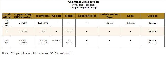
Posted by: pbanders Feb 9 2010, 05:19 PM
Jeff's right, pure Cu is very soft. Ever hear of the Bronze Age?  Think of Be as an improvement over Sn.
Posted by: jk76.914 Feb 9 2010, 07:08 PM
The Niton XL-800 is also an X-ray fluroescence instrument. Here's an excerpt from a DOE test of the XL-800 dated April 2000: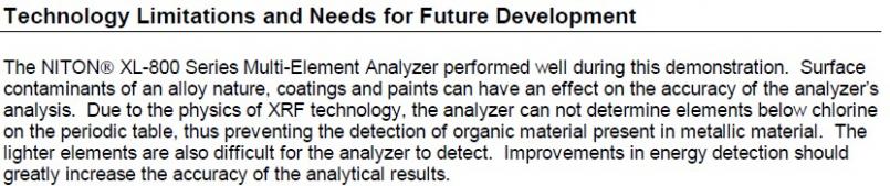
Note that chlorine is 17 on the periodic table!! That's higher than aluminum (13). AND BERYLLIUM IS 4!! The detection technology is called "proportional count". Newer technology is available now, using "silicon pin diode" detectors. As I understand it, the issue is signal-to-noise ratio. The lower atomic number elements may register, but their peak is lost in noise. The newer technology improves the SN ratio and they become visible. The Thermo-Fischer Scientific unit I tested my samples on (in November '08 BTW) using the newer technology can differentiate down to atomic number 12 (magnesium). There's yet a newer technology that can go lower, but it's moot for beryllium, because it's invisible to X-rays.
So sorry to say, I think we both fell into the same pit. XRF is a fantastic technology, but it's blind to Be.
----------------------------------------------------------------------------------------
Meanwhile, back to the stainless steel idea. I ran some tests over the weekend on my copper and my stainless diaphrams (#1 and #4 in previous pics). I measured inductance vs. vacuum, but with the aneroid cells locked (filled with gorilla glue, clamped at nominal thickness during cure. Photo later tonight). I wanted to see the incremental effect of the enrichment diaphram alone. I had previously tested cells with the diaphram locked, and saw that they were amazingly linear from 0" to about 22", across several sets of cells of wide vintage, including the one stainless set. (post that chart later)
So the two conditions were:
first test, called SS-
1. outer screw set flush with bushing on cell side of diaphram (set before assembly)
2. inner screw set to an inductance of .85H at high vacuum (seated diaphram)
3. full load stop set to inductance of 1.00H at 0" vacuum.
This setting maxes the bias of the diaphram towards the cells, with a total travel of 0.15H. (0.15H is kinda arbitrary, but not far off from Mr. Anders's 0.12H typical travel- I think. Can't find the reference in his MPS Bible at the moment, but I think it's 0.12H)
second test, SS+
1. inner screw set to inductance = 1.00 at 0", full load stop removed for this test
2. outer screw set to inductance = .85H at high vacuum (careful not to turn the inner screw while setting.)
This biases the diaphram position away from the cells as far as possible, but still with the same 0.15H travel.
The two curves represent the adjustment limits of the stainless steel diaphram.
A picture's worth 10000 words: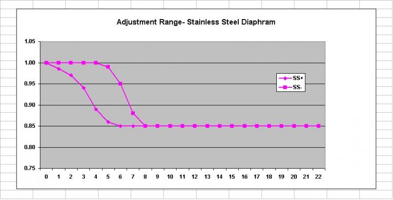
Comments
1. SS- curve looks like it blends smoothly with the 1.00 upper limit. It really doesn't. If I had the resolution to do 4.5" or even 4.25" it would crash abruptly into the limit.
2. That's quite a range, in both slope and vacuum at which the diaphram begins to lift off the stop. Quite an opportunity for careful tuning if you really got good at this.
Oh, and here's the copper (diaphram #1, from the bottom of the lake) range.... I call it Cu-2P (copper- 2 pleat)-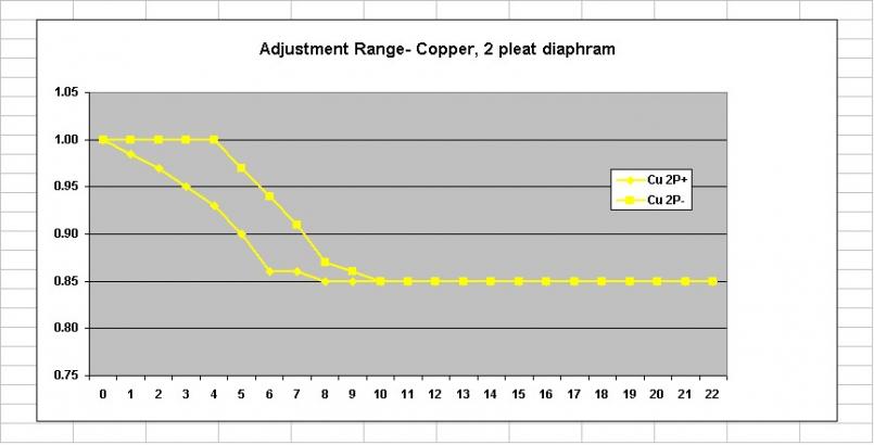
Note that in Cu-2P+ the diaphram starts to lift off the stop at 7", then stalls at 6", and then resumes a fairly smooth transition the rest of the way to 1.00H. I reran these points several times, and it repeated the same. I suspect that there is a point where the 2 pleat diaphram resists strain, which allows stress to build up, until it pops past that point and then behaves itself. This only occurs for Cu-2P+ because the entire test range for Cu-2P- is beyond this point.
I still want to test the brass diaphram (#3 in picture). I may get a chance yet tonight, but I'll probably post the chart tomorrow.... Like I said, this is getting interesting!
That's enough for now. I've got to drill some holes in my frozen lawn and put reflectors along my driveway. Big storm coming tomorrow.
Posted by: Bleyseng Feb 9 2010, 07:20 PM
yeah but, Eric's testing showed no Be just Al,bronze, etc in trace amounts. You tell me the alloy mix and I should be able to get it. He deals in airplane metals..
Posted by: jk76.914 Feb 11 2010, 04:59 AM
Quick update. I did the crappy brass characterization. Not surprisingly (I guess), it only had about 0.16H of total travel- when I set the outer screw flush with the bushing in diaphram on the cell side, and then set the inner screw to 0.85H at high vacuum (diaphram seated), I only had about 1.01H at 0". So basically there is no adjustment range the way I'm testing. This is almost certainly because of its stiffness. At least it has a pretty smooth transition.
In reality, assuming I need to get 0.12H of contribution out of the diaphram, there would be a little adjustment.... Anyway here's the curve-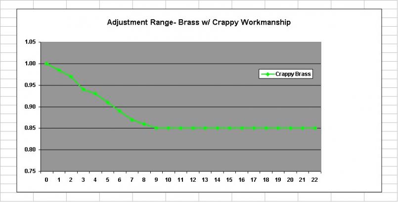
Next step, I plotted a curve of a cell, without effect of diaphram. This was easy, I just snugged the full load stop down, pinning the diaphram between full load and idle stops.
I've plotted a lot of cells (SS below), and they are almost perfectly coincident, cell to cell. But none tail up at high vacuum due to their expansion being limited by the limit arms?? Gotta figure this one out...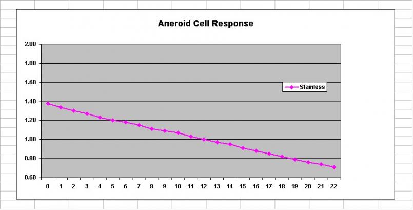
Note that my inductance meter is NOT calibrated to a known standard, so it may be different from one that any of you guys use. It's repeatable though, so for what I'm trying to do, it's working fine and was very reasonably priced.
Gotta go to work. My last plots superimpose the cell curve and the diaphram curves. I'm looking for most range of adjustment and smooth transition for each diaphram type, and it's looking like the stainless one is going to be it. Of course, I don't have a stock copper w/ 3 pleats that isn't ruptured to test for comparison...
I'll post those last plots tonight...
Jim
Posted by: jk76.914 Feb 20 2010, 11:43 AM
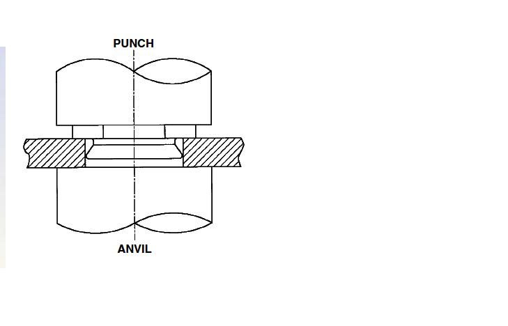
Yesterday during lunch, we tried to press apart a diaphram hub. One of the guys machined some custom blocking, and we set it up in a hydraulic press. Well, at 3500 pounds, it finally began to yield. Unfortunately, it was the hub that was yielding, not the presumed press-fit. (I used one of my crudely made brass aftermarket diaphrams.)
So we sectioned it. Take a look.... 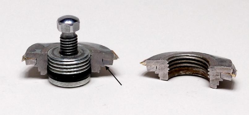
As you can see, there are three parts. The hub, the diaphram, and a locking ring. There is a ridge on the hub that retains the lock ring. The lock ring is continuous around the diameter of the hub, as is the ridge.
All I can think of is that they chilled the hub/diaphram, heated the ring, and then assembled them. As they equalized in temperature, the ring tightened down on the diaphram due to the champher on the underside of the ridge on the hub (arrow). I determine the alloy next week using XRF, so I can figure out temperatures involved. Back of the envelope calculation says they needed a temperature difference of 5000 degrees or so to clear a 1/64" ridge if it's standard steel, which would have melted everything.... or else I need a new envelope.
You can see the distortion in the hub from our attempts to press it apart.
Posted by: underthetire Feb 20 2010, 12:39 PM
did the ring seem hard yet gummy when you cut it? A company I used to work for invented shape memory alloys, in fact even invented shrink tubing. The alloy was frozen in LN, then was stretched using a tapered arbor. Once it came up to temp, it would be back in it's original shape. These were and probably still are used on all the composite aircraft for the hydraulic systems. Guess if you have a hydraulic leak with a composite airframe, you get paper mache.
Very cool testing your doing BTW.
Posted by: ArtechnikA Feb 20 2010, 02:16 PM
So we sectioned it. Take a look....
As you can see, there are three parts. The hub, the diaphram, and a locking ring. There is a ridge on the hub that retains the lock ring. The lock ring is continuous around the diameter of the hub, as is the ridge.
All I can think of is that they chilled the hub/diaphram, heated the ring, and then assembled them.
To my untrained eye it appears that the flange of the hub that retains the lock ring might have been swaged in place. This technique would have been in keeping with mass-production (i.e. low-cost) quantities and readily available with late-'60's tooling.
Memory-effect metals and cryogenic techniques were known then, but were considered 'aerospace-level' technology - not economy-car stuff...
Posted by: kwales Feb 20 2010, 05:19 PM
I think yer making this too hard.
I agree with the swaging technique.
Smack a really hard fastener into a soft material with the right tools and I gurantee the soft material will flow in place.
I've used a nut type fastener called a Pem Nut since the 70's. You drill a precision hole in aluminum, insert the Pem Nut and smack the crap out of it with a BF hammer. It swages the aluminum into the recess in the nut and holds everything in place. While not identical, the 914 part might use a similar technique with a Euro fastener.
Pem works on mild steel if the steel is softer than the Pem fastener. Pems come in nuts, studs, etc,
Attached are two pics of one type of a flush mount nut. One is shown inserted, and the second pic shows the optional swaging tooling...
We used the BFH technique or with some types, used the screw to pull the nut into place.
Pems might work for a new diaphragm.
Attached image(s)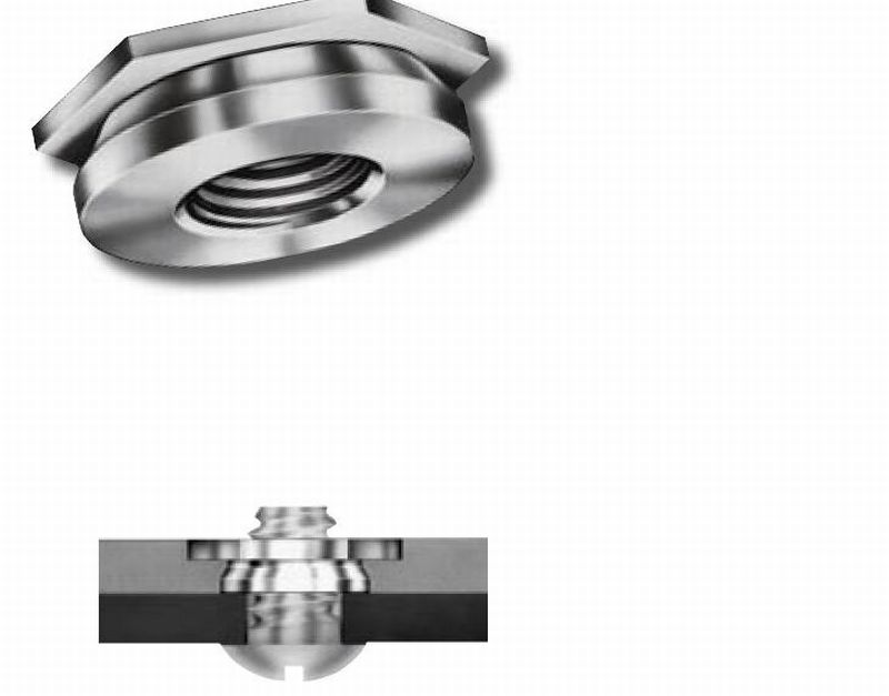
Posted by: 76-914 Feb 20 2010, 06:58 PM
Great stuff here. I'll bet ya'll will have it figured out in no time. ![popcorn[1].gif](style_emoticons/default/popcorn[1].gif)
Posted by: jk76.914 Feb 21 2010, 07:43 AM
I think yer making this too hard.
I agree with the swaging technique.
Smack a really hard fastener into a soft material with the right tools and I gurantee the soft material will flow in place.
I've used a nut type fastener called a Pem Nut since the 70's. You drill a precision hole in aluminum, insert the Pem Nut and smack the crap out of it with a BF hammer. It swages the aluminum into the recess in the nut and holds everything in place. While not identical, the 914 part might use a similar technique with a Euro fastener.
Pem works on mild steel if the steel is softer than the Pem fastener. Pems come in nuts, studs, etc,
Attached are two pics of one type of a flush mount nut. One is shown inserted, and the second pic shows the optional swaging tooling...
We used the BFH technique or with some types, used the screw to pull the nut into place.
Pems might work for a new diaphragm.
That's a great idea. I've also used PEMs. I'll be checking the material alloys this week at work, maybe tomorrow, and if the ring is softer than the hug, this is probably how they did it. Of course, for a repro, this could be how to do it regardless.
Posted by: pbanders Feb 21 2010, 09:23 AM
Great stuff, a few comments. One, the design of the adjustment flange is rather complex. Not only do you need it to be retained in the diaphragm, but you also need to supply a precise, smooth recess where the O-ring seal on the outer screw can slide, and maintain vacuum integrity during adjustment. From reviewing the Bosch patents, I can see that early on they tried to make "fixed" flanges without the outer screw adjuster, but apparently they found too much variation in the settings.
One more thing is that a low-effort way of getting what we want might be to work directly with a rebuilder, who has already done the tooling for the flange and the mounting process. Getting them to adopt a different diaphram material or design that gives better characteristics would be in their interests, and they could have a new market in selling diaphragms for something like $50 a pop. I think SLITS knows who picked up all of the stuff from Bret when they sold the business.
Posted by: kwales Feb 21 2010, 12:05 PM
I think they make the PEM's out of the stuff that they use for the hinges of hell.
No matter how hard they are hit, the other stuff deforms- not the PEM.
Looks like the factory design is a sandwitch of a hard PEM like fastener, the soft diaphragm placed onto the fastener, and a steel or aluminum washer that captures the diaphragm on the fastener. The washer does the deforming.
The particular one that I added above is a flush mount fastener and might require a sandwitch of a washer, the diaphragm, and a second washer on the other side of the diaphragm. That way, the soft diaphragm is pinched between the washers, and the washers do the deforming- not the diaphragm.
Posted by: McMark Feb 21 2010, 12:09 PM
You guys are awesome for researching this... 
Posted by: jk76.914 Feb 21 2010, 12:13 PM
Great stuff, a few comments. One, the design of the adjustment flange is rather complex. Not only do you need it to be retained in the diaphragm, but you also need to supply a precise, smooth recess where the O-ring seal on the outer screw can slide, and maintain vacuum integrity during adjustment. From reviewing the Bosch patents, I can see that early on they tried to make "fixed" flanges without the outer screw adjuster, but apparently they found too much variation in the settings.
One more thing is that a low-effort way of getting what we want might be to work directly with a rebuilder, who has already done the tooling for the flange and the mounting process. Getting them to adopt a different diaphram material or design that gives better characteristics would be in their interests, and they could have a new market in selling diaphragms for something like $50 a pop. I think SLITS knows who picked up all of the stuff from Bret when they sold the business.
Diaphram #3 in my original post is from a fresh Bret rebuild. It's the one I call "crappy brass", and it has no adjustment range, because it's so stiff. Their approach to mounting the diaphram maybe isn't so bad though. They cut the original diaphram back to where it's just a collar, and then soldered the replacement (with its oversize ID) onto the remnant of the original copper one. Quick and dirty, not very esthetically pleasing maybe, but maybe workable. It may work with a quality diaphram as well.
I have to photo the other side of my stainless diaphram and post it. I think it's assembled differently.... Later today....
Posted by: jk76.914 Feb 21 2010, 01:49 PM
OK. I took some more photos. These three are copper, stainless, copper. (presumably beryllium-copper).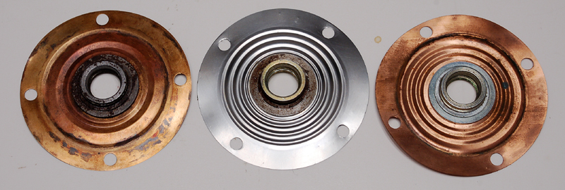
Both copper use the same hub attachment design- the one I sectioned earlier. The stainless one is different. It is definitely swaged together (arrows) in 6 places.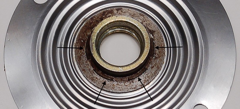
Could it be possible that the 2-pleat copper type was a factory attempt at addressing the fatigue problem? Now I'm more strongly doubting the stainless being factory, because both the material and the hub design are different. Of course, if Bosch put engineering into design improvements, they wouldn't have necessarily stopped at diaphram material. And the stainless hub has another difference- it protrudes higher off the diaphram on the ambient side. This allows for more adjustment before the outer screw's o-ring exits the hub and starts leaking.....
Also, I peeled the lock ring off one section of the hub, and both the lock ring and the hub are definitely steel- they're magnetic. I'll find out what alloy later this week.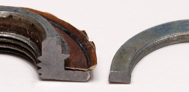
Posted by: jk76.914 Feb 27 2010, 04:57 PM
Picked up a -010 MPS this week, allegedly from a Volvo 142E, circa 1972. But it's got to be late 60s vintage, so I'm thinking it's probably from a P1800.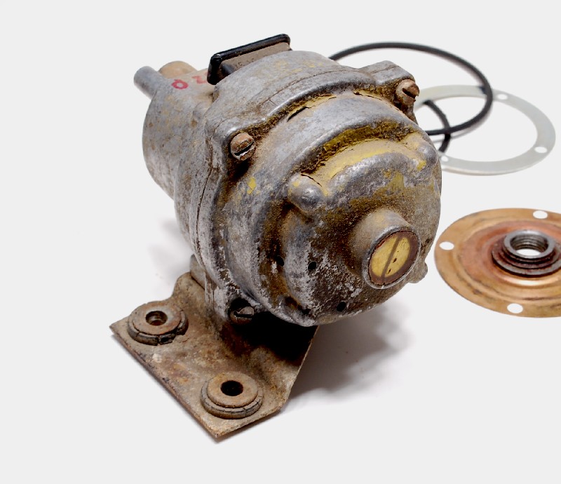
It's a long nose. These guys have a mechanical damper built into the snout, inside of the spring, which requires a longer snout to account for the extra piece. I'll post a photo later.
Also, note that there are four drilled holes in the diaphram end, instead of cast slots like every other one I've ever seen. Kinda hard to see in the photo. Two are visible at about 3 o'clock, one on the face and one on the side. The other two are maybe 45 degrees below that.
I profiled it, and then took it apart. It's a rebuilt, non-leaker, and sports yet a 5th diaphram type. The diaphram hub is idential to stock, which I'm now convinced is swaged as suggested by kwales.
Anyway, the diaphram is a copper alloy, and it has 3 pleats, but the pleats range in width from wide on the outside to narrow near the hub. I've dubbed this the "3 asymmetrical pleat" diaphram, and she's a beauty!!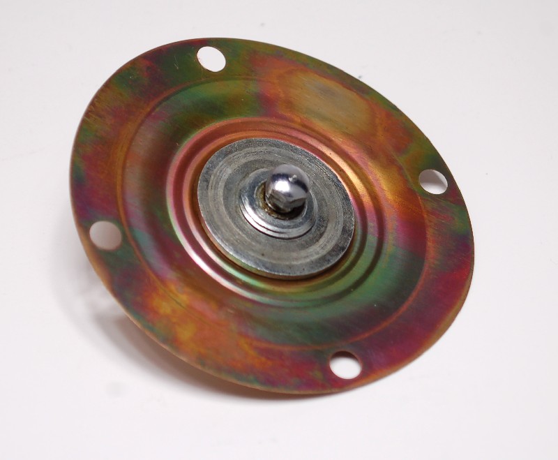
I loaded the diaphram up into my test MPS, with its filled aneroid-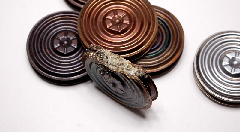
and profiled its adjustment range-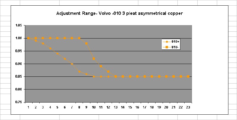
This is the widest adjustment range I've found yet. It beats out the stainless one, though not by much.
In case anyone is wondering what I'm going to do with this, well, first I want to see which diaphram material/design has the greatest adjustment range, and then I'm intend to try my own materials and see what I can come up with that is comparable, or better than stock. I'll make a die set to press diaphrams from, and I've reverse-engineered a hub that will close with a lock nut so I can try different materials.
On that note- I also picked up a -035 MPS- another Volvo, this one probably truly is from a 142E. It's short-nosed, original-riveted, and it doesn't leak. Tomorrow, I'm actually going to open it up (not for the squeemish, opening a non-leaking stock MPS!!!) so I can profile the stock copper diaphram to compare with all of these alternate designs.
Posted by: McMark Feb 27 2010, 11:43 PM

Posted by: rick 918-S Feb 28 2010, 12:23 AM
Love this science stuff!
Posted by: ArtechnikA Feb 28 2010, 05:16 AM
The diaphram hub is idential to stock, which I'm now convinced is swaged as suggested by kwales.
...or someone ...
Posted by: 914Sixer Feb 28 2010, 07:35 AM
Really amazing reading!! 
Posted by: Thomas J Bliznik Feb 28 2010, 08:30 AM
Really amazing reading!!
 I agree, amazing reading.
 My question?? Has anyone thought about a simple solution??? Contact Bosch engineering and ask for the material composition or who their supplier was?? Now that MPS's are obsolete Bosch might release this info from their engineering files. Somebody at Bosch knows. Just a thought

I don't have any contacts, but maybe someone on the board knows someone???
How about George @ AA????
Tom
Posted by: jk76.914 Feb 28 2010, 11:33 AM
Really amazing reading!!
I agree, amazing reading. My question?? Has anyone thought about a simple solution??? Contact Bosch engineering and ask for the material composition or who their supplier was?? Now that MPS's are obsolete Bosch might release this info from their engineering files. Somebody at Bosch knows. Just a thought
I don't have any contacts, but maybe someone on the board knows someone???
How about George @ AA????
Tom
Great idea!! Other questions are whether the tooling still exists, would it be possible to arrange for one more run (maybe 500 pieces??), and if we could speak with someone who can shed some light on the design changes that Bosch made along the way... it's possible that more than one of these 5 diaphrams are original Bosch, just representing design evolution.
Anybody have any connections at Bosch?
(I'm having fun, though, so I'm going to pursue my trail further either way.)
Jim
Posted by: pbanders Mar 1 2010, 11:14 AM
It would be great if we could get Bosch to supply a run of replacement diaprhagms.
I might point out that even if a replacement diaphragm were available, that rebuilding and calibrating the MPS isn't a trival thing. Here are the steps as I see it:
1. Remove the epoxy from the full load stop - don't attempt to remove the full load stop yet.
2. Drill out the case rivets to remove the top.
3. Using a 3/8" tip flat screwdriver (filed to fit the slot tightly), drive the full-load stop through and out of the top half of the case. Don't try to back it out, as there is epoxy holding the threads. Heat and WD-40 will help this operation. You may want to break it loose before drilling out the case rivets first, as it may make it easier to secure the MPS.
4. Remove the old diaphragm and remove the adjuster assembly from it, reinstall in the new diaphragm to approximately the same depth. Use a vernier to set it exactly.
5. Clean out the interior of the MPS with contact cleaner.
6. Install the diaphragm. Assuming we don't have a supply of new gaskets, install the old gasket, and use a thin layer of heavy grease to seal it.
7. Tap the case and bore the top to accept screws to secure the top.
8. Install the top, leave the full-load stop out for now.
9. Using the tables on my MPS page (see my sig for links) and a Wavetek LCR55 meter, set the inner and outer adjusters as described on the page. Install the full-load stop as described on the page.
10. At this point, the MPS is approximately adjusted and should work. To properly optimize the adjustment, you'll need to set the part load and full load mixtures using a dynamometer and a gas analyzer. Suggested settings for stock 2.0L motors are part-load (i.e. 2500 rpm, low throttle angle) at a CO of 2.5% to 3.0%, and a full-load (i.e. 4000 rpm, wide-open throttle angle) at a CO of 4.5% to 5.0%.
To those out there who have done this before, please feel free to edit and correct this procedure as required.
Posted by: pbanders Mar 1 2010, 11:20 AM
Anybody have any connections at Bosch?
FWIW, this is the correct contact info in Germany. I've had a little bit of luck in the past, perhaps someone else will do better than I did.
Robert Bosch GmbH
Gasoline Systems Division
P.O. Box 30 02 40
D-70442 Stuttgart
Telephone +49 711 811-0
Posted by: pbanders Mar 1 2010, 11:29 AM
FYI, are others aware of the Bosch Classic web shop on eBay?
http://stores.shop.ebay.de/Bosch-Klassik-Teilevermittlung__W0QQ_armrsZ1
Not a lot of 914 parts, but some are there.
Posted by: pbanders Mar 1 2010, 06:02 PM
FWIW, I sent an email to the guy in Bosch Germany who was the press coordinator for the 40th anniversary of D-Jetronic to see if he can put us in touch with anyone at Bosch who might be able to help us out.
Posted by: jk76.914 Mar 1 2010, 06:30 PM
FWIW, I sent an email to the guy in Bosch Germany who was the press coordinator for the 40th anniversary of D-Jetronic to see if he can put us in touch with anyone at Bosch who might be able to help us out.
That's a great lead. Better than cold calls to Bosch.
Posted by: jk76.914 Mar 1 2010, 06:45 PM
OK, some images from that -010 Volvo MPS. First the coil, with damper.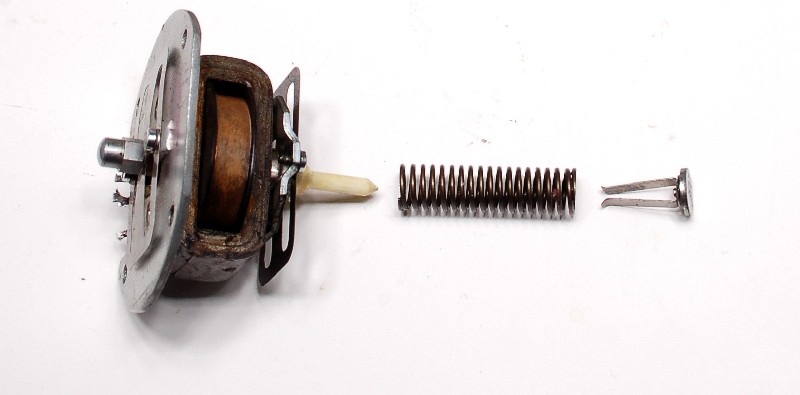
Then a surprise- never seen one of these-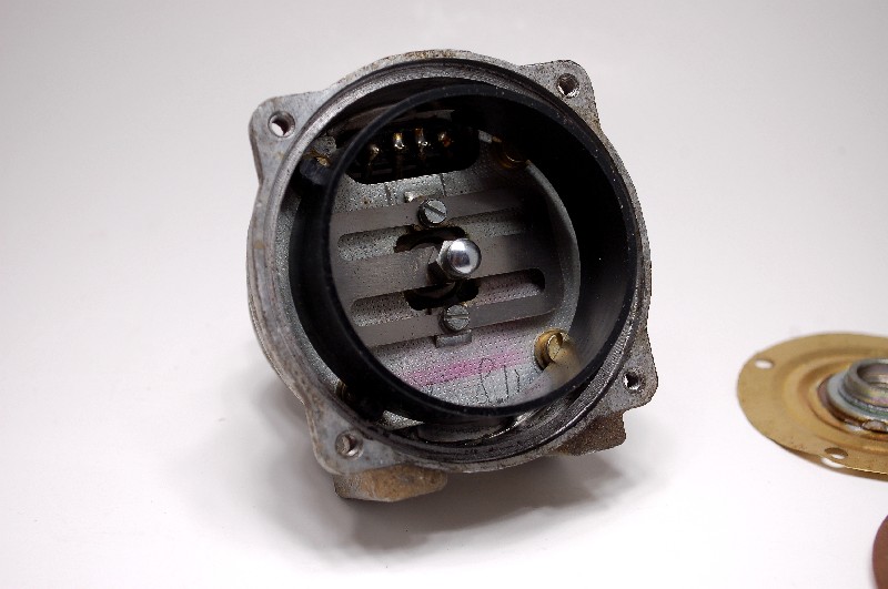
Any ideas what it could be for? I have an idea, but maybe someone knows for sure... Looks factory. Can't imagine a rebuilder tooling something like it.
Cleaning a couple of housings with special purpose MPS cleaner....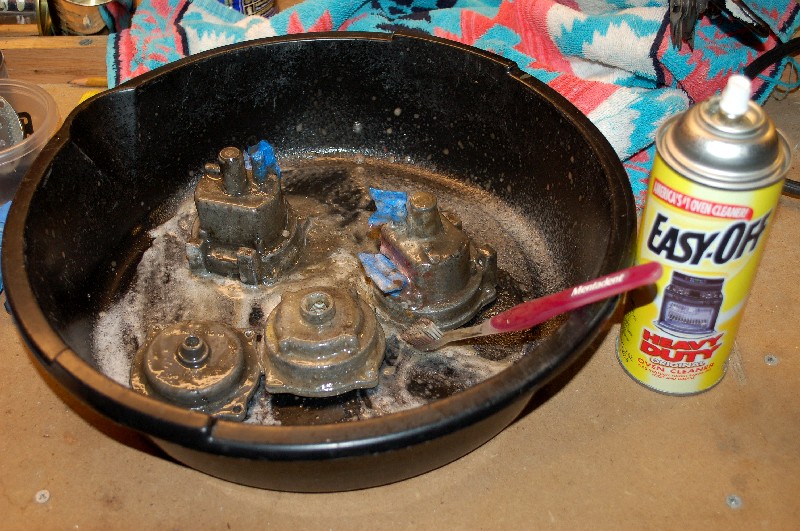
Posted by: jk76.914 Mar 1 2010, 07:09 PM
Nice clean housing. Not perfect, but not bad. You can see the vent holes I was talking about.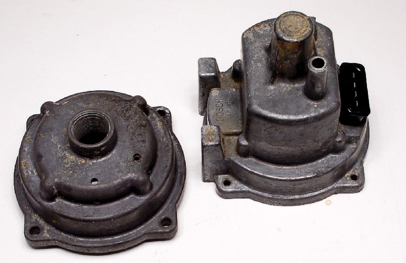
Also, took apart that other alleged Volvo 142E unit. The non-leaking, riveted, -035. Found the holy grail of diaphrams- a perfect stock piece-
I'll profile it later.... Almost time for 24.
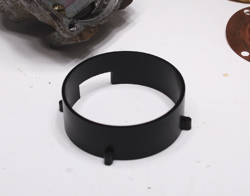
Also found another of those plastic rings... Why do the two Volvo pieces have these? The cells fit inside, but it's a loose fit.... What're they for?
Posted by: Bleyseng Mar 2 2010, 09:21 AM
Also found another of those plastic rings... Why do the two Volvo pieces have these? The cells fit inside, but it's a loose fit.... What're they for?
I have found a few in even the 914 MPSs. They are for holding the cells from flopping around.
Posted by: pbanders Mar 3 2010, 10:48 AM
FYI, I've made some interesting connections at Bosch, in the Bosch Automotive Tradition group, which is dedicated to supporting classics. I'll have some more info for everyone soon. They're starting a their own program of rebuilding components. They already can do the AAR, and will be starting rebuilding MPS's next month - to Bosch standards, with Bosch parts, and Bosch calibration standards. No idea of cost or logistics. Will pass on more info as I get it.
Posted by: pbanders Mar 3 2010, 11:14 AM
OK, here's a bit more info. There's a newsletter you can subscribe to at the Bosch Automotive Tradition web site, see:
http://www.automotive-tradition.com/en/newsletter/index.htm?locale=en
Here's a link to the December issue:
http://www.automotive-tradition.com/en/newsletter/media/newsletter_dez_09_en.pdf
Open it and you'll see an item about "Individual Remanufacturing of Induction Tube Pressure Sensors" - a.k.a. the manifold pressure sensor. They have a link to their 1:1 REMAN site with more info. This site has a lot of information available over in the sidebar under "Parts".
They're also interested in remanufacturing the throttle position sensor. Since we already have someone doing that, I'm going to try to get them hooked up.
IMO, if we could get Bosch to do a rebuild and recalibrate at a "reasonable" price (IMO, $300 USD), these rebuilds would likely be as good as or superior to anything we'd be able to do on our own. Worth a try, at least.
Posted by: kwales Mar 3 2010, 02:18 PM
While you are on a roll,
Howsabout fuel injectors.......
Posted by: SirAndy Mar 3 2010, 02:33 PM
Howsabout fuel injectors.......
We should give them a list and have 1,000 members sign it ...
 Andy
Andy
Posted by: pbanders Mar 3 2010, 02:51 PM
Howsabout fuel injectors.......
We should give them a list and have 1,000 members sign it ...
AndyHe asked me about other problematic parts, and fuel injectors were at the top of my list.
Posted by: jk76.914 Mar 3 2010, 06:55 PM
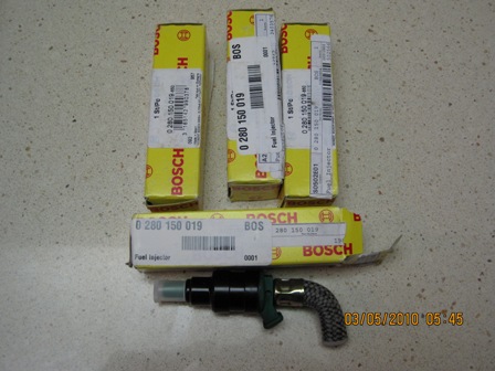
Brad's link links to Bosch Traditions, which in turn links to their storefront on eBay-Germany. They have all three of our fuel injectors! Take a look- about 160 Euro.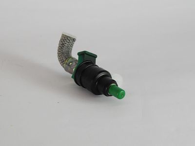
Here's the link- http://cgi.ebay.de/0280150019-Einspritzventil-VW-Porsche-914-Bosch_W0QQitemZ120486903264QQcmdZViewItemQQptZAutoteile_Zubeh%C3%B6r?hash=item1c0d943de0
and the yellow one (1.7) is here-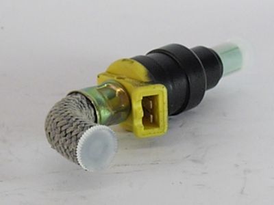
http://cgi.ebay.de/0280150009-Einspritzventil-VW-Porsche-914-Bosch_W0QQitemZ110465066012QQcmdZViewItemQQptZAutoteile_Zubeh%C3%B6r?hash=item19b83b241c
and the 1.8 is here-
http://cgi.ebay.de/0280150112-Einspritzventil-VW-Porsche-914-Bosch_W0QQitemZ110453005172QQcmdZViewItemQQptZAutoteile_Zubeh%C3%B6r?hash=item19b7831b74
Posted by: jk76.914 Mar 3 2010, 07:17 PM
Did anybody say throttle position sensor?
Here's the 1.7L http://cgi.ebay.de/0280120021-Drosselklappensensor-VW-Porsche-914-Bosch_W0QQitemZ120520908428QQcmdZViewItemQQptZAutoteile_Zubeh%C3%B6r?hash=item1c0f9b1e8c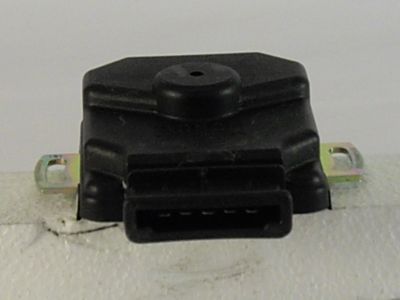
And just to tease us- here's an MPS for a Opel Admiral- Later type, no diaphram, but it's "only" 175 euro. If that's the ball park for a -037, -043, or -049, COUNT ME IN!! http://cgi.ebay.de/0280100105-Saugrohrdruck-drucksensor-Opel-Admiral_W0QQitemZ110421358909QQcmdZViewItemQQptZAutoteile_Zubeh%C3%B6r?hash=item19b5a0393d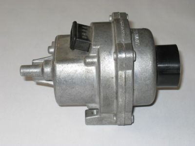
Posted by: computers4kids Mar 3 2010, 07:39 PM
Yikes...that's $218 US dollars
Great Thread and Read!
Attached image(s)
Posted by: jk76.914 Mar 3 2010, 08:05 PM
Yikes...that's $218 US dollars
Great Thread and Read!
OK. How'd you get the English version?!?!?!?!?!
Jim
Posted by: jk76.914 Mar 3 2010, 08:55 PM
Nevermind. I found the english version at eBay-UK. Groan. They list a -066 MPS, which is our type with the diaphram, for 1050 euros. That's $1437. But that's brand new. (-066 is for a Volvo 3.0L six cylinder.) Maybe there's still hope for the 1-for-1 rebuild program.
http://cgi.ebay.co.uk/Bosch-0280100066-DRUCKFUHLER-Saugrohr-Benzin-VOLVO_W0QQitemZ120321257155QQcmdZViewItemQQptZAutoteile_Zubeh%C3%B6r?hash=item1c03b4aec3
Posted by: pbanders Mar 3 2010, 09:39 PM
Yeah, I should have been more clear. I knew the had the injectors on the site, but I think these are NOS. When they're gone, they're gone. The Reman operation is actually fabricating new parts, I'd like to coax them into remanufacturing the more "consumable" parts, including injectors.
I'm hoping to hear back from them tomorrow.
Posted by: computers4kids Mar 3 2010, 10:26 PM
Yikes...that's $218 US dollars
Great Thread and Read!
OK. How'd you get the English version?!?!?!?!?!
Jim
http://translate.google.com/#.
Posted by: Bleyseng Mar 4 2010, 01:24 AM
Maybe I can send them the box of 50 dead MPSs siiting in my garage so they can fix em and sell cheap....$1000 is way too much, $300 is a good target as a brand new diaphram will last another 30 years!
Posted by: jk76.914 Mar 4 2010, 04:34 AM
Too bad you can't just get a kit. Diaphram, o-rings for adjuster screws, and main seal, for maybe $100.
Posted by: McMark Mar 4 2010, 12:33 PM
Jim, tuning is the real issue with a home rebuild kit. The best part about a factory rebuild would be that it's a 5min install and you can trust that it's right.
Posted by: jk76.914 Mar 4 2010, 07:53 PM
I know. But I also I think there's an opportunity for someone to write up a procedure, maybe do a video, on tuning D-jet to their own engine. The initial tuning done by the car manufacturers was a compromise to begin with. They had to account for production variation, variation in quality of gasoline, climates where the cars would be sold and driven, etc. And they didn't have the benefit of O2 sensors and the feedback loops they provide to help tune on-the-fly. Couple that to the fact that most of us have done SOME mods to our engines, and I think time is ripe for us to figure this thing out.
I keep thinking about that 1.99L Volvo 142E being rated at 135 HP. Or the 1985cc Saab GLE at 118 HP as exemples of where D-Jet can go with the right cam, timing, exhaust, C.R., etc. Not to mention the 2L Cosworth Vega at 122 HP-
Posted by: mtndawg Mar 5 2010, 09:46 AM
I sent an email to Bosch via the Traditions web site telling them that I'm interested in having a 1.7L mps rebuilt. Someone named Matthias responded to me saying that they are looking at pricing for this process that would be done at Bosch in Germany and to keep an eye on the newsletter.
Posted by: Bleyseng Mar 5 2010, 09:58 AM
Jim, tuning is the real issue with a home rebuild kit. The best part about a factory rebuild would be that it's a 5min install and you can trust that it's right.
Tuning to the known settings is pretty easy, the problem is most engines are slightly modified from stock these days. Close but tuning with a LM1 O2 setup gets you right there. New outta the box MPSs from Bosch would be set to their settings from what, 30 years ago for Brand New engines.
I have had a couple of NOS 043 that were set all over the place...and I set them to the "correct" setting I knew worked right.
I would rather have a repair kit of new parts to do the job myself so I could tune the MPS to a engine with its own quirks.
Posted by: jk76.914 Mar 5 2010, 04:56 PM
Jim, tuning is the real issue with a home rebuild kit. The best part about a factory rebuild would be that it's a 5min install and you can trust that it's right.
Tuning to the known settings is pretty easy, the problem is most engines are slightly modified from stock these days. Close but tuning with a LM1 O2 setup gets you right there. New outta the box MPSs from Bosch would be set to their settings from what, 30 years ago for Brand New engines.
I have had a couple of NOS 043 that were set all over the place...and I set them to the "correct" setting I knew worked right.
I would rather have a repair kit of new parts to do the job myself so I could tune the MPS to a engine with its own quirks.
I'm with you. The carb guys haven't weighed in. Would they take a new set of Webers and plunk them onto the car, and then never dial them in? I think not.
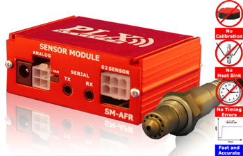
And either way, you really should have access to an AFR meter. I'm going to try and use a PLX Devices unit. Got it for Christmas. Haven't tried it yet... And inductance meters have come way down. I think I paid $40 for mine brand new.
Posted by: 1988Hawk Mar 5 2010, 07:03 PM
 4 new 2.0 injectors from Otto, not cheap but reasonably priced.
Posted by: pbanders Mar 5 2010, 11:06 PM
Matthias is the same guy I'm communicating with, same info I received regarding when the program will start. I'll communicate more on this stuff next week. I've had a medical issue since Wednesday that's kept me out of action, I should be back to speed by Monday.
Posted by: jk76.914 Mar 8 2010, 05:24 AM
Exchanged emails with Herr Matthias Klumpp at Bosch Traditions. I requested that Bosch make available a rebuild kit, composed of 3 seals plus diaphram. He replied that they were going to offer a rebuild service soon. So I replied again that the rebuild is easy, it's the tuning to the engine that is more difficult and that it really should be done for each engine anyway. So I requested again- "would Bosch consider offering the repair kit separately as described?"
Maybe with more requests they'll think about it. If they're offering the rebuild service, they obviously have these 4 parts.
Jim
Posted by: ArtechnikA Mar 8 2010, 06:07 AM
I would be quite surprised if Bosch made a rebuild kit available. Pleasantly surprised, but surprised. It's not their style. There's not much money in it for them, and by keeping the price of the 'secret service' high it keeps demand for the parts low.
I believe they're only pursuing the 'rebuild service' because if emissions parts are really unavailable, they need to make this representation to the appropriate governing authorities (e.g. EPA, DOT, CARB) and that (manufacturer's NLA statement) removes the 'original equipment' requirement - which would kill their golden-egg-laying goose well and truly.
If you had only to meet tailpipe numbers and could do it with any induction system, would you do it with Bosch D-Jet parts?
Posted by: Larouex Mar 8 2010, 09:29 AM
Jim, tuning is the real issue with a home rebuild kit. The best part about a factory rebuild would be that it's a 5min install and you can trust that it's right.
Tuning to the known settings is pretty easy, the problem is most engines are slightly modified from stock these days. Close but tuning with a LM1 O2 setup gets you right there. New outta the box MPSs from Bosch would be set to their settings from what, 30 years ago for Brand New engines.
I have had a couple of NOS 043 that were set all over the place...and I set them to the "correct" setting I knew worked right.
I would rather have a repair kit of new parts to do the job myself so I could tune the MPS to a engine with its own quirks.
I'm with you. The carb guys haven't weighed in. Would they take a new set of Webers and plunk them onto the car, and then never dial them in? I think not.
And either way, you really should have access to an AFR meter. I'm going to try and use a PLX Devices unit. Got it for Christmas. Haven't tried it yet... And inductance meters have come way down. I think I paid $40 for mine brand new.
Sorry to be uninformed, but what does this AFR do and how do you use it to tweak a DJet? Thanks, I am just wanting to learn how to get the most out of my setup.
Larouex
Posted by: pbanders Mar 8 2010, 10:36 AM
I would be quite surprised if Bosch made a rebuild kit available. Pleasantly surprised, but surprised. It's not their style. There's not much money in it for them, and by keeping the price of the 'secret service' high it keeps demand for the parts low.
I believe they're only pursuing the 'rebuild service' because if emissions parts are really unavailable, they need to make this representation to the appropriate governing authorities (e.g. EPA, DOT, CARB) and that (manufacturer's NLA statement) removes the 'original equipment' requirement - which would kill their golden-egg-laying goose well and truly.
If you had only to meet tailpipe numbers and could do it with any induction system, would you do it with Bosch D-Jet parts?
I agree, I see very little incentive for Bosch to offer a kit. I'd be glad to see one, however!
For tailpipe emissions, D-Jet is a decent solution, especially compared to some of the carb arrangements I've seen. Where D-Jet beats carbs on emissions is under all of the various running conditions outside of part-load, which is why carbs fell out of favor once the Feds started the program in '70.
One manufacturer who stayed with carbs a long, long time was Honda. Anyone remember the carbs on some of their cars from the early '80's? Absolutely insane number of vacuum hoses and tacked-on systems to manage emissions. They worked fine when the cars were new, but once the hoses started to go, look out.
Posted by: Bleyseng Mar 8 2010, 10:52 AM
Jim, tuning is the real issue with a home rebuild kit. The best part about a factory rebuild would be that it's a 5min install and you can trust that it's right.
Tuning to the known settings is pretty easy, the problem is most engines are slightly modified from stock these days. Close but tuning with a LM1 O2 setup gets you right there. New outta the box MPSs from Bosch would be set to their settings from what, 30 years ago for Brand New engines.
I have had a couple of NOS 043 that were set all over the place...and I set them to the "correct" setting I knew worked right.
I would rather have a repair kit of new parts to do the job myself so I could tune the MPS to a engine with its own quirks.
I'm with you. The carb guys haven't weighed in. Would they take a new set of Webers and plunk them onto the car, and then never dial them in? I think not.
And either way, you really should have access to an AFR meter. I'm going to try and use a PLX Devices unit. Got it for Christmas. Haven't tried it yet... And inductance meters have come way down. I think I paid $40 for mine brand new.
Sorry to be uninformed, but what does this AFR do and how do you use it to tweak a DJet? Thanks, I am just wanting to learn how to get the most out of my setup.
Larouex
First you weld a "bung" onto the exhaust so you can mount the O2 sensor.
Then you drive around at partload (2000-2500rpms) and record it onto a laptop.
Then a WOT run
Check your results and see what your AFR is varying conditions to see what your average AFR it. It should be between 13.7 and 14 to one at Part load.
WOT should be 12 to one to start and end at 13 to one at 5000 rpms.
Idle is set with the knob.
Posted by: pbanders Mar 8 2010, 11:05 AM
First you weld a "bung" onto the exhaust so you can mount the O2 sensor.
Then you drive around at partload (2000-2500rpms) and record it onto a laptop.
Then a WOT run
Check your results and see what your AFR is varying conditions to see what your average AFR it. It should be between 13.7 and 14 to one at Part load.
WOT should be 12 to one to start and end at 13 to one at 5000 rpms.
Idle is set with the knob.
Those are the same ratios I recommend, too. If everything in your FI checks out (especially check on the fuel pressure) and you're running rich at part-load, you'll need to adjust the MPS to get the mixture right.
From what I can tell, these engines will run just fine with extremely rich mixtures, part-load at 13:1 or less. These high levels may work OK, but contribute to higher pollution, poor fuel economy, cylinder wall wear, and oil contamination.
Posted by: kconway Mar 8 2010, 11:08 AM
So if Bosch does a rebuild kit over a complete rebuild I've got buy a AFR and a laptop, cut holes in my exhaust, and learn to weld? Or, I guess I could buy a rebuild kit and then try to find a mechanic that knows Djet and is willing to do the tuning at a reasonable price.
Ugg, doesn't make sense for 95% of the 914 owners out there.
Posted by: pbanders Mar 8 2010, 11:18 AM
So if Bosch does a rebuild kit over a complete rebuild I've got buy a AFR and a laptop, cut holes in my exhaust, and learn to weld? Or, I guess I could buy a rebuild kit and then try to find a mechanic that knows Djet and is willing to do the tuning at a reasonable price.
Ugg, doesn't make sense for 95% of the 914 owners out there.
I agree (again). While it may cost a wad of cash to get an NOS or Bosch rebuilt MPS, the investment in the stuff required to DIY, plus the time, is likely to cost more.
Regardless of whether the MPS is NOS or rebuilt, I still suggest a dyno evaluation for all D-Jet owners, with gas analysis. That way you'll know for sure what your part-load and full-load mixtures are. Shouldn't cost more than $100, and you'll get that cool HP graph, too.
Posted by: jk76.914 Mar 8 2010, 07:49 PM
So if Bosch does a rebuild kit over a complete rebuild I've got buy a AFR and a laptop, cut holes in my exhaust, and learn to weld? Or, I guess I could buy a rebuild kit and then try to find a mechanic that knows Djet and is willing to do the tuning at a reasonable price.
Ugg, doesn't make sense for 95% of the 914 owners out there.
I agree (again). While it may cost a wad of cash to get an NOS or Bosch rebuilt MPS, the investment in the stuff required to DIY, plus the time, is likely to cost more.
Well, I suppose. But I'm not doing anything here based on cash flow analysis. I'm having fun, and I'm learning lots of new things. That's pretty much what I've been doing with this car for the past 28 years that I've owned it.
And I still don't see why this isn't like dialing in new carbs..... which lots of people have learned or taught themselves to do...
I have a theory on that plastic ring.....
Posted by: jk76.914 Mar 8 2010, 08:04 PM
So if Bosch does a rebuild kit over a complete rebuild I've got buy a AFR and a laptop, cut holes in my exhaust, and learn to weld? Or, I guess I could buy a rebuild kit and then try to find a mechanic that knows Djet and is willing to do the tuning at a reasonable price.
Ugg, doesn't make sense for 95% of the 914 owners out there.
It'd never be an either/or. Bosch would never do a rebuild kit only over a complete rebuild. So you'll never have to face this situation.
Posted by: Bleyseng Mar 8 2010, 09:18 PM
Even when Bosch comes out with a new or rebuilt MPS, everyone should do as Brad suggests..put it on a dyno and check your AFR at part load and WOT.
of find a friend who has a LM1 to check it.
The original MPSs were set up for brand new engines off the VW line. No one has a brand new engine, most rebuilds are mostly new or reconditioned parts..and who has brand new injectors, fuel pump, etc.
Posted by: 3d914 Oct 17 2010, 11:13 PM
Any update on this? Curious 914 owners are watching!
Posted by: jk76.914 Oct 18 2010, 03:15 AM
Any update on this? Curious 914 owners are watching!
Not much at the moment from me. I'll get back into this this winter. Rebuild of my front end will pre-empt much else for a while, though.
I was able to confirm presence of Be in my stock diaphram, using EDS at work. That's Energy Dispersive Spectroscopy. Like XRF, it also can't determine component %-age in an alloy for elements below atomic number 5 or 6, because it also depends on X-ray. The only way I've found is a "wet" process, where the sample is dissolved in nitric acid, then separated somehow into component elements, and measured. I haven't pursued where I could get this done, or for how much. But at least this is confirmed this to be a beryllium alloy. Probably any of a couple of the Brush-Wellman sheet stocks would be suitable.
Also, since I have several "good" diaphrams to work with, and I've characterized their ranges of adjustment, I'll be concentrating on how to tune them to my engine. In May, I replaced the original muffler on my Bursch system with a much quieter one, and added an O2 sensor bung. I have a lambda meter from PLX devices ready to install, along with 1K pot to replace the ballast resistor, and some assorted other parts. I'm thinking of making up a console where a co-pilot can tune some settings on the road, even (potentially) simulate an MPS with a variable inductance to establish "ideal" curve for my engine. Then see how close I can come to mapping on on the bench. Getting all the way through this process is my goal for next summer- after the front end is done.
I'll update from time to time along the way.
Posted by: trfrick Dec 6 2010, 02:25 PM
This is what I received from Bosch regarding rebuilding 041 MPS:
The refurbishing of a 0 280 100 041 will cost 349 EUR gross (incl. 19% German VAT) plus shipping costs.
If interested please send the MPS to my hands:
Robert Bosch GmbH
Matthias Klumpp (AA/ATR)
Auf der Breit 4
76227 Karlsruhe
Germany
I will then forward the part to our plant where the refurbishing is done. Please contact me again so that I can send you a so called "pro-forma invoice" for customs duty. Shipping should be done by TNT Express.
-> If the part is not repairable you will get it back unrepaired.
-> If it's okay (within its tolerances) we will bill you with examination costs of 19 EUR.
-> If it's defective but repairable you will have to pay the refurbishing costs by buying a special item in our eBay store http://stores.ebay.de/Bosch-Klassik-Teilvermittlung - you can pay via PayPal or via bank transfer. The refurbishing will start once the money has been transferred.
P.S.: If you have a VAT ID we can create an invoice without sales tax.
Mit freundlichen Grüßen / Best regards
Matthias Klumpp
Robert Bosch GmbH
Automotive Tradition (AA/ATR2)
www.bosch.com
www.automotive-tradition.de
stores.ebay.de/Bosch-Klassik-Teilevermittlung
Tel. +49(0)721 942-1660
Fax +49(0)721 942-2000
Automotive-Tradition@de.bosch.com
Sitz: Stuttgart, Registergericht: Amtsgericht Stuttgart, HRB 14000;
Aufsichtsratsvorsitzender: Hermann Scholl; Geschäftsführung: Franz Fehrenbach, Siegfried Dais;
Bernd Bohr, Rudolf Colm, Volkmar Denner, Wolfgang Malchow, Peter Marks,
Peter Tyroller; Stefan Asenkerschbaumer, Uwe Raschke, Wolf-Henning Scheider
Posted by: r_towle Dec 6 2010, 02:52 PM
fantastic news
Posted by: jk76.914 Dec 6 2010, 07:04 PM
Well, I guess it's time to get back at this. Here's my plan for the near term-
- make some new gasket sets on a laser cutter. I have a sheet of .100" neoprene, and I'll try cutting out the big ring seal and the smaller ring that goes around the outer adjustment nut. Then I can assemble a test MPS using one of the diaphrams that gave a lot of adjustment range, with no leaks (fingers crossed).
- I'm going to try and set up to map vacuum vs. lambda on the fly. I've been thinking about this all summer off and on. I picked up a Pico Technology PicoLog 1012. This is a data logger that plugs into, and is powered by a USB port in a laptop. It actually has 12 channels, but I only will use 2. One channel will be connected to the linear output of my PLX AFR sensor module. This outputs a voltage from 0-5vdc that is proportional to AFR. This is one of the reasons I got the PLX. The second output will log vacuum. To do this, I still need to buy a GM MAP sensor. These were used in many GM models in the early to mid-90's, and they output a voltage 0-5vdc that is linear with manifold pressure from 0-1bar. (There are also 2 bar and 3 bar versions for turbo applications, but I only need 1 bar and they're cheaper- about $35).
I got set up for this with the purchase of the PLX (actually a Christmas gift that I haven't tried out yet, 50 weeks later), and the install of my Walker SS muffler on my Bursch exhaust that I documented in another thread last May While I had the muffler welded up, we installed the bung for the O2 sensor.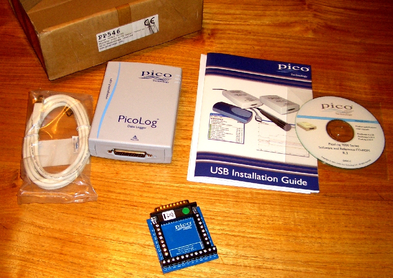
I'm thinking the only thing left is the GM MAP sensor, and then hooking it all up.
The data logger came with software that I can set up to capture data (voltages, actually) from both channels simultaneously at pretty much my choice of speeds. It can only capture 8000 data events in it's memory, across both channels, so I'll probably start with 100 events/second, which will give me 40 seconds of data. So as I drive down the road, I'll have someone else with the lap top who can download the data once every 40 seconds or minute or so, and then start collecting again.
The raw data can be downloaded into Excel, and then plotted as a scatter diagram. I'll plot each point with X axis as voltage from the MAP, and Y axis as voltage from the PLX. I expect that as I move the throttle, the points will be all over the place because there is a lag between when the vacuum changes (throttle opens or closes) and the AFR settles in to the new point. But if I drive smoothly, with constant throttle, they should cluster about a horizontal line that roughly represents AFR at each vacuum level. I'll vary speed and even gears to get 40 second long samples at various loads.
By overlaying the calibration curve from my MPS, I can visually see where the MPS curve needs to change to bring lambda better into alignment with desired. The work I did mapping MPS adjustment ranges will feed into my selecting the right diaphram and setup to tune the whole thing in iteratively.
At least that's plan.
Posted by: jk76.914 Dec 6 2010, 07:14 PM
I've set aside trying to make diaphrams for now. Since they're available in rebuilds from Bosch (albeit at big $$), or can be harvested from 1.7 MPS's for a bit less, the common problem now seems to be how to tune the MPS to a specific engine. Whether it's a new MPS, a good used one, or a rebuild, factory settings are at best a compromise. Our engines are old and worn, or rebuilt with tweaks from original. Even a newly blueprinted engine should have it's MPS checked, because even original factory settings were a compromise in the first place.
I had a scheme where I would use a Type 3 MPS (no diaphram, only aneroid cells) as a slave, and measure vacuum level that resulted in desired AFR. This could then be translated into inductance to plot desired MPS curve. I think it would have worked, but it would have been very awkward. Then I hit on this idea.... We'll see. 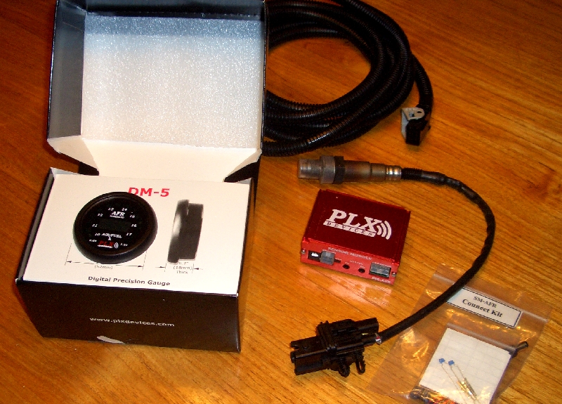
Posted by: jk76.914 Dec 6 2010, 07:20 PM
I also toyed with the idea of making a test diaphram out of the sheet neoprene. It would have been an interesting experiment, and I'm sure it would have worked, at least at high vacuum and low vacuum, but I had no idea how it would behave in the transition region, or the impact of temperature or aging.
If I do decide to dabble in diaphram fabrication again, I'm sure this will be my first try. Just to find out.
Bung with sensor-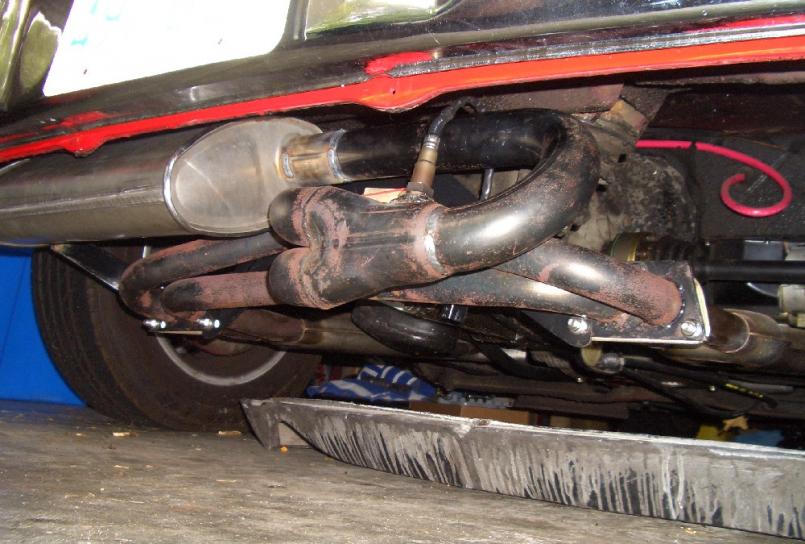
Posted by: jk76.914 Dec 6 2010, 07:29 PM
Here's a loose end from last spring. I dissected that riveted, non-leaking Volvo MPS to find a pristine diaphram. But I never showed the adjustment range, so here it is. It beats any other diaphram I tested-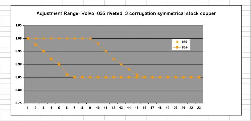
Posted by: SirAndy Dec 6 2010, 09:50 PM
Too bad. That's the one item that could help a lot of people keep their original FI ...
Posted by: Bleyseng Dec 7 2010, 06:35 AM
Here's a loose end from last spring. I dissected that riveted, non-leaking Volvo MPS to find a pristine diaphram. But I never showed the adjustment range, so here it is. It beats any other diaphram I tested-
Wish you would make em like this! They have better transition than any of the other made.
Posted by: jk76.914 Dec 7 2010, 07:22 AM
I know. Something had to give. If I focus on making new ones somehow, I don't get my car "finished" for a while. I'm 58, and I've set an objective of having it "done" by the time I'm 60. (I started taking it apart when I turned 50, btw, after owning it and driving it for 20 summers.) So I only have 2 summers left to meet my goal. Figuring out how to tune it to a specific engine (mine, for now) helps me get there, while tooling for a new run of diaphrams doesn't. So that's the story.
I'm mulling over how to get diaphrams from Bosch. Doesn't seem right that they have them sitting over there in bins while our 35+ year old ones are dying one-by-one....
Posted by: Bleyseng Dec 7 2010, 08:46 AM
I know. Something had to give. If I focus on making new ones somehow, I don't get my car "finished" for a while. I'm 58, and I've set an objective of having it "done" by the time I'm 60. (I started taking it apart when I turned 50, btw, after owning it and driving it for 20 summers.) So I only have 2 summers left to meet my goal. Figuring out how to tune it to a specific engine (mine, for now) helps me get there, while tooling for a new run of diaphrams doesn't. So that's the story.
I'm mulling over how to get diaphrams from Bosch. Doesn't seem right that they have them sitting over there in bins while our 35+ year old ones are dying one-by-one....
What, that's your car and its not done?
I am 58 too and miss driving my car and can't decide if I want to ship it to Suriname. There are few twistys here but there are the Saturday night drag races!
Posted by: realred914 Dec 7 2010, 02:22 PM
Wow, really great info! With your permission and credit to you, can I use some of the photos and data on my MPS page (see link in sig)?
You mention the full-load diaphragm provides altitude compensation. This is only true under heavy and full-load conditions. The only MPS's that provided part-load altitude compensation were the 0 280 100 100 series that was used on the MB's. These units lacked the full-load diaphragm (full-load was sensed by the throttle switch) and had an altitude compensation cell that was connected to the atmosphere through a holow screw.
I agree with your observation that the lower the "stiffness", or spring constant of the diaphragm, the less effect it will have on the transition characteristic. For any material used, the thickness and pleat design will vary. Reliability and resistance to fatigue failure is also an important consideration in the material selection.
Crafting the aneroid cells out of a different material and/or a different pleat design would be tricky. The issue here is to identically duplicate the pressure vs. displacement characteristic of the OEM cells. It would interesting to compare the SS cells to the OEM cells for this characteristic.
Positioning of the full-load stop is also critical to defining the transition region, setting the proper full-load mixture, and reducing the mechanical stress on the full-load diaphragm. Bosch sets most MPS to a 2 in. Hg engagement, though I have seen some units set to 4 in. Hg.
Again, great stuff, thanks for sharing it with us.
On the data and photos- you're welcome to them, with one caveat. We're using beryllium in a project at work, and one of the characteristics is that it is transparent to X-rays. So I need to verify that our XRF is capable of detecting Be in alloys. If not, those numbers may not be right. I'm travelling until the end of the week, so it'll be Friday before I can get with the lab guy. We have other means of measuring alloys that I can pursue that don't use X-Rays. The brass and stainless alloys should be correct.... Sorry to everyone if my info was premature. I'll be sure to confirm or correct it shortly.
That makes sense about the full load only altitude compensation. The diaphram has to lift off the stop for any compensation to occur.... makes sense. I have a 0 280 100 120 MPS from a Cosworth Vega that is like the MB MPS you described... but then it is, as you said, part of the 100 series... Interesting that Chevrolet licensed the technology directly from Bendix, not Bosch, but all the comonents are Bosch.
I measured several (maybe 6) aneroid cells sets using the same MPS, but with the diaphram locked. I set their inductance to a common value at the same vacuum, and then measured and plotted the curves. Their slopes are identical. I plotted them on the same axis, and they are as coincident as I can imagine. These 6 included a set from a 0 280 100 001 (early type 3, no diaphram, probably the simplest MPS out there) AND the stainless steel set.
So now I'm setting up to measure the vacuum/L curves for diaphrams alone. I sacrificed a set of perfectly good aneroid cells by cutting them open and filling them with gorilla glue to set them. I let them harden in my vise with the jaws set to original cell dimension (gorilla glue expands when it hardens, and would have pushed them open). First thing I found was that the cells ARE MANUFACTURED WITH PARTIAL VACUUM INSIDE!! As soon as my cutoff blade broke through, they expanded out and became flacid. Anyway, now that they're hardened up, I'm going to measure inductance curves, which will represent the response of the diaphrams alone.
I'm thinking that I can combine the diaphram and cell responses using superposition and get pretty close to what the finished MPS should be.... getting interesting.
if the x-ray window in your instrument is made of berilium, detecting berilium is out of the question.
Posted by: realred914 Dec 7 2010, 02:29 PM
looks like i will will be needing to get my mps claibrated soon with teh new 96 mm motor getting built for me.
a wide band O2 sendor seems like a nice way to adjust it by.
i may end up doing this too.
i have mapped four mps untis. me and a friend had using a vacuum pump, gage and a henry meter, each was different, some strikingly so.
the thing is we never tested it otehr than by seat of the pants, so that got me thinking of an O2 sendor, i used on on a triumph for tunning a carb, tricky but doable, it should be fun  with the multible screws to turn on the MPS !!!
any advice on which screw does what and so forth when adjsuting?
Posted by: jk76.914 Dec 7 2010, 08:14 PM
looks like i will will be needing to get my mps claibrated soon with teh new 96 mm motor getting built for me.
a wide band O2 sendor seems like a nice way to adjust it by.
any advice on which screw does what and so forth when adjsuting?
I recommend Brad Anders articles on the D-Jet at http://members.rennlist.com/pbanders/manifold_pressure_sensor.htm
That will tell you which screws to turn and so forth. There are other adjustments outside of the MPS though-
- fuel pressure. It MAY be interesting to try a regulator that is modulated by manifold vacuum. I'm curious if it'd be possible to use a diaphram-less MPS that is properly set up with such a regulator. That'd be a great way to solve the diaphram availability and reliability issue! Later applications did exactly that- Mercedes and Cosworth-Vega (OMG!) to name two.
- ballast resistor value.
- timing- definitely affects vacuum, and anything that affects vacuum affects MPS and therefore AFR with D-Jet
Some or all of these are documented in other threads by others here at 914world.
As far as MPS is concerned, the mapping I've done with each of these various diaphrams evaluates the range that they can be set within, by pre-biasing the diaphram towards or away from the coil to max limits of the adjustment. As you can see, the pristine stock diaphram has a very w-i-d-e range available. I'm hoping to see where within that wide range is best for my engine.
When I get my data logger running, I should have a visual tool to see what's going on across the range of vacuum the engine sees, and I can try these ideas, one variable at a time...
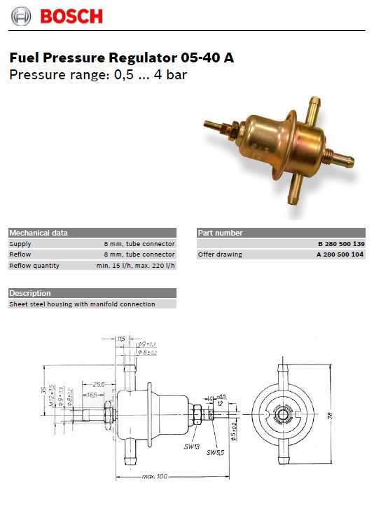
Posted by: 914 shifter Dec 7 2010, 10:01 PM
diaphram-less MPS that is properly set up with such a regulator.this sounds too easy.i hope that someone has success with this idea 
Posted by: bandjoey Dec 7 2010, 10:40 PM
Yes. I've just read this front to back and it's interesting as hell. But, can anyone tell me why salt makes the ice colder when making ice cream! 
I'm also thankful we have a community of scientific types to do this work. It's on the track of keeping our cars on the road. Original parts are getting too $$$ out of hand from mfg's like Bosch. THANKS  First Class Work.
Posted by: Bleyseng Dec 8 2010, 07:13 AM
if you are running a stock rebuild motor setting the MPS via a Wavetek is the easiest way and works. We have the known settings for the Wavetek to do this.
if you are running a non stock cam you must adjust the inner and outer screws for the proper AFR and slope, then set the WOT stop screw for the WOT AFR (12.5 to one). Using a LM1 hooked up properly doing multiple runs is the only way I know how to do this. On a roller dyno or on the road works fine.
Posted by: realred914 Dec 8 2010, 10:11 AM
if you are running a stock rebuild motor setting the MPS via a Wavetek is the easiest way and works. We have the known settings for the Wavetek to do this.
if you are running a non stock cam you must adjust the inner and outer screws for the proper AFR and slope, then set the WOT stop screw for the WOT AFR (12.5 to one). Using a LM1 hooked up properly doing multiple runs is the only way I know how to do this. On a roller dyno or on the road works fine.
looks like an O2 sensor should be in my plans then???? My motor will be modified, 96 mm pistons, and a Elgin 330-1 cam. I had used the LM-1 system I borrowed once for tunning a triumph carbed car, actually I found the readout to never be stable, so it was an exercise in frustration. maybe a function of the carb not being stable, it was a bicth cuase it was smog controlled car!
how well does teh LM-1 system work on our D-jet cars, is the signal pretty stable when driving? (no dnyo, so i would be tuning on the street)
Posted by: Bleyseng Dec 8 2010, 11:12 AM
once you weld a bung in the exhaust in the right place it works great...if you have a laptop and the rest of the wires and adapters you can log it in.
like I said, it takes several runs adjusting the screws ever so slightly to set the AFR correctly. Once you are close you can feel the hp come around along with smooth transition from idle, partload and WOT.
Posted by: jk76.914 Jan 3 2011, 05:23 AM
Thinking ahead- Since it's now winter, I'm thinking I'll hook up my monitoring rig on my daughter's '99 VW Cabrio. Should be an easy trial- I only need to tap into the O2 sensor, plus add the GM MAP sensor. That'll give me a baseline with a "modern" EFI system, so I can see what the scatter cloud looks like...
Also, thinking about this GM MAP sensor (<$30 at RockAuto): I know you can't practically emulate the inductor in the MPS, but what if one were to use an MPS with no diaphram, and then use the output from a modern MAP sensor for enrichment only? The aneroid cells would get the mixture close, and the ECU would be happy, but full throttle enrichment would be from a separate circuit controlled by the MAP sensor.
Looking at the circuit description in Brad's article, TS2 is the leg of a simple voltage divider. The circuit in the ECU is reacting to the voltage derived to extend the pulse via the PWM circuit. Why not boost this voltage a bit for enrichment, controlled by a couple of op-amps driven by the MAP sensor output? The circuit I'm starting to think about would be adjustable for when the enrichment starts, rate of enrichment vs. decreasing vacuum (slope), and max enrichment limit. Since running with TS2 open or shorted results in too rich or too lean (respectively) to run, seems like this ECU input may provide plenty of range to pull it off.
Maybe a hybrid approach like this can be a path to elimination of the diaphram? What do you think Brad? Others?
Posted by: jk76.914 Jan 9 2011, 08:55 PM
Made a bit of progress. I received my MAP sensor from RockAuto, and was able to sneak down to the basement and plot the output voltage vs. vacuum. The chart is below and it's unbelievably linear. This is what it's supposed to do, but it still amazed me. The other thing I noticed when I was taking the data was that it is extremely sensitive- one pump on my hand vacuum pump and the needle flys to 14" vacuum. Three pumps and it's all the way up to 27". This is very different from an MPS, and tells me the chamber volume above the "diaphram" is tiny.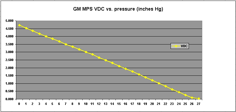
There is active circuitry inside, and the module requires +5v power input. The output is volts DC. I had to gin up 5 volt source, which I did using my constant-current battery charger I'm working on and a 7805 regular that I've had kicking around my random electronics parts box since 1977.
Below is a photo of my test setup. Not much to look at, but it did the job.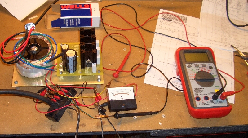
The analog meter is for the battery charger. I used the DVM on the right for the readings. With the MAP sensor, it'd be easy to make an electrical vacuum gauge, whether analog or digital. Interesting idea.
I've researched the '99 Cabrio, and there are two O2 sensors- one before and one after the cat. Next step is to translate the setup to the car, learn how to use the data logger, and collect some baseline data.....
Posted by: rick 918-S Jan 9 2011, 09:40 PM
I'm always facinated when I check this thread. You really have a grasp on this thing. It is so interesting to read and try to figure out what your up to. Let me tell you, I have no clue..
Posted by: jk76.914 Jan 10 2011, 05:31 AM
I'm always facinated when I check this thread. You really have a grasp on this thing. It is so interesting to read and try to figure out what your up to. Let me tell you, I have no clue..
Sometimes I drift around a bit, I admit. I'm kind of excited about my track now though- first this tool to visually see, on my laptop, where my AFR is vs. vacuum during normal driving, to tune my MPS.
And then try some things to use a MAP sensor and some simple circuitry to maybe fool the ECU into low vacuum enrichment with a no-diaphram MPS. All the plots I did last winter got me thinking along the lines of separating the contribution of the diaphram from that of the aneroid cell.
Powered by Invision Power Board (http://www.invisionboard.com)
© Invision Power Services (http://www.invisionpower.com)