Printable Version of Topic
Click here to view this topic in its original format
914World.com _ 914World Garage _ How's my valvetrain geometry look?
Posted by: Cevan Apr 29 2010, 08:36 PM
I'm attempting this for the first time. I'm using 1.7 rockers that have been decked .060 and 911 swivel adjusters. The cam I'm using has an advertised lift of .465 for both intake and exhaust.
On the intake side, my lift was .482 with the geometry at its best, but still not straight. It seemed I needed to back the adjuster out even farther. I had the adjuster about 3 turns in from when the threads started disappearing.
So I used .030 washers under each pad to see what shimming the rocker assembly up would do (this is only to see how shims will effect things). At about 3 turns in (as above) on the intake, I got a net lift of .482, within the 5% limit per Jake's valvetrain geometry article. 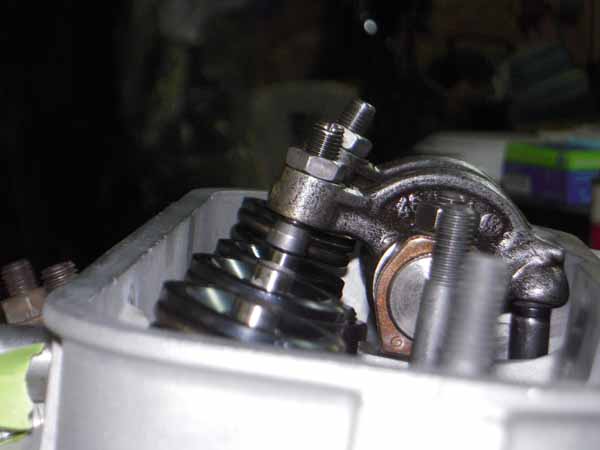
So I go over to the exhaust side. Again, I need to keep backing the adjust out to get the geometry looking correct. At 3 turns in, my net lift is .453. 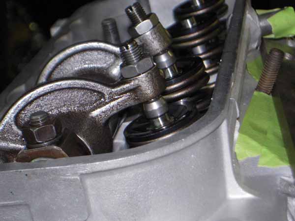
Both the intake (.482) and exhaust (.453) net lift are within 5% of the advertised lift. Is this much of a difference going to be a problem? The motor is a 2056.
Posted by: Racer Chris Apr 30 2010, 05:04 AM
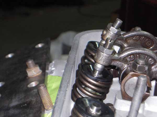
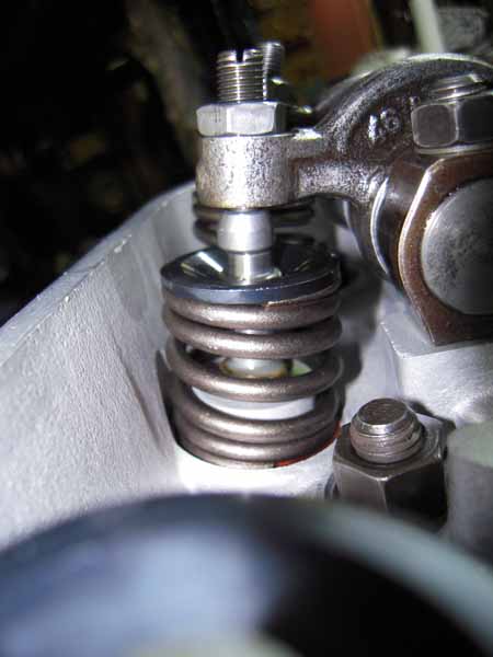
Are those pictures at full lift?
The adjuster should be in line with the valve at half-lift.
Posted by: Cevan Apr 30 2010, 06:00 AM
The pictures are all at half of net lift.
Posted by: Vacca Rabite Apr 30 2010, 06:30 AM
At 1/2 lift, the look good, like they are in 1 plane with each other.
Zach
Posted by: Dr Evil Apr 30 2010, 07:14 AM
I cant believe Zach didnt mention, you are going to need to grind down and re-slot the the adjusters lest they impact your valve cover over and over again  Looks good otherwise.
Posted by: Cevan Apr 30 2010, 07:47 AM
I was going to check the adjuster to valve cover clearance with clay. I assume I'll need to take about .030 off. Will I have an issue with the difference in intake and exhaust lift?
Posted by: Vacca Rabite Apr 30 2010, 07:48 AM
You should not, so long as you are within the 5% tolerance... We had to grind down all of mine a little and re-slot them.
Zach
Posted by: type11969 Apr 30 2010, 07:52 AM

I cant believe Zach didnt mention, you are going to need to grind down and re-slot the the adjusters lest they impact your valve cover over and over again
Looks good otherwise.Checking this is a good idea but I have two engines running 1.7L rockers with 911 adjusters and have no valve cover interference issues. Just saying you don't need to pull out the grinder yet.
-Chris
Posted by: Cevan Apr 30 2010, 07:55 AM
I cant believe Zach didnt mention, you are going to need to grind down and re-slot the the adjusters lest they impact your valve cover over and over again
Looks good otherwise.Checking this is a good idea but I have two engines running 1.7L rockers with 911 adjusters and have no valve cover interference issues. Just saying you don't need to pull out the grinder yet.
-Chris
I think because I'm using a shim uder the rocker pads, everything will sit a little higher.
Posted by: type11969 Apr 30 2010, 07:59 AM
Ahh, missed that
Posted by: Vacca Rabite Apr 30 2010, 08:02 AM
I had to space mine out a little to get them right. W/O the spacers, I could not get the geo right.
I ended up using my calipers to find 4 washers exactly the same thickness AND the thickness I needed to get things to work. Once spaced, the geo pretty much fell right into place. I think we ended up grinding off a little more then the thickness of the washers off the top of each adjuster and then just recutting the slot. on mine they JUST barely kissed the inside of the rocker cover when the engine was cold, but you could hear them start to "tack tack tack tack" against the rocker cover as it heated up.
Zach
Posted by: Cevan Apr 30 2010, 01:48 PM
I ordered a spacer kit from Aircooled.net, which has 3 different thickness shims. Right now I'm just using .030 washers to see if that would work.
In the meantime, I've got to remove some material from the other 3 aluminum rockershaft spacers to get the right gap (.003-.005 I believe). Always something to do. These are definately not slap together engines.
Posted by: Cevan May 2 2010, 02:37 PM
With the .030 rocker pad spacers in place, I used some clay on the back side of the rocker cover. With the valves closed, I have at least .100 between the top of the adjusters and the cover. I think this will be enough.
Posted by: Als914 May 2 2010, 02:55 PM
With the .030 rocker pad spacers in place, I used some clay on the back side of the rocker cover. With the valves closed, I have at least .100 between the top of the adjusters and the cover. I think this will be enough.
Are you using stock valve covers. I am in the process of setting up my VT geometry but I have the polished aluminum covers. I have had these on the heads for years so I can't remember which one or the other has a taller internal stance?
Posted by: Cevan May 2 2010, 04:33 PM
With the .030 rocker pad spacers in place, I used some clay on the back side of the rocker cover. With the valves closed, I have at least .100 between the top of the adjusters and the cover. I think this will be enough.
Are you using stock valve covers. I am in the process of setting up my VT geometry but I have the polished aluminum covers. I have had these on the heads for years so I can't remember which one or the other has a taller internal stance?
I'm using the stock covers. I haven't heard any good things about the aftermarket covers that are bolted on.
Posted by: Als914 May 2 2010, 05:10 PM
With the .030 rocker pad spacers in place, I used some clay on the back side of the rocker cover. With the valves closed, I have at least .100 between the top of the adjusters and the cover. I think this will be enough.
Are you using stock valve covers. I am in the process of setting up my VT geometry but I have the polished aluminum covers. I have had these on the heads for years so I can't remember which one or the other has a taller internal stance?
I'm using the stock covers. I haven't heard any good things about the aftermarket covers that are bolted on.
I have had them on my daily driver for over 200K miles (I am the original owner) with no issues. My question wasn't what your preference is, I was hoping to find if there is a difference in internal hight from the gasket seat, one to the other.
Posted by: r_towle May 2 2010, 05:15 PM
Chris,
It looks wicked pissa.
Posted by: Cevan May 2 2010, 06:34 PM
With the .030 rocker pad spacers in place, I used some clay on the back side of the rocker cover. With the valves closed, I have at least .100 between the top of the adjusters and the cover. I think this will be enough.
Are you using stock valve covers. I am in the process of setting up my VT geometry but I have the polished aluminum covers. I have had these on the heads for years so I can't remember which one or the other has a taller internal stance?
I'm using the stock covers. I haven't heard any good things about the aftermarket covers that are bolted on.
I have had them on my daily driver for over 200K miles (I am the original owner) with no issues. My question wasn't what your preference is, I was hoping to find if there is a difference in internal hight from the gasket seat, one to the other.
No problem. I only have experience (limited at that) with the OEM covers.
Posted by: Dave_Darling May 2 2010, 10:22 PM
The stock covers curve inward at the top and bottom. The aftermarket ones are just about square, so they have more room at the top and bottom.
And I'm quite surprised that you're getting the bolt-on ones to fit and seal up! Good job, hopefully you'll write up a thread on how you did it.
--DD
Posted by: watsonrx13 May 3 2010, 05:55 AM
I'm attempting this for the first time. I'm using 1.7 rockers that have been decked .060 and 911 swivel adjusters. The cam I'm using has an advertised lift of .465 for both intake and exhaust.
On the intake side, my lift was .482 with the geometry at its best, but still not straight. It seemed I needed to back the adjuster out even farther. I had the adjuster about 3 turns in from when the threads started disappearing.
So I used .030 washers under each pad to see what shimming the rocker assembly up would do (this is only to see how shims will effect things). At about 3 turns in (as above) on the intake, I got a net lift of .482, within the 5% limit per Jake's valvetrain geometry article.
So I go over to the exhaust side. Again, I need to keep backing the adjust out to get the geometry looking correct. At 3 turns in, my net lift is .453.
Both the intake (.482) and exhaust (.453) net lift are within 5% of the advertised lift. Is this much of a difference going to be a problem? The motor is a 2056.
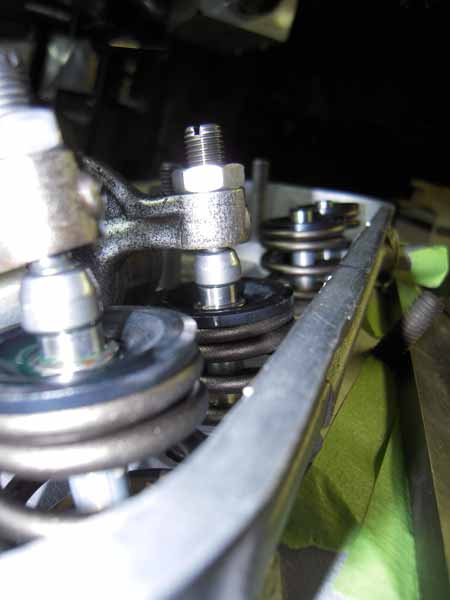
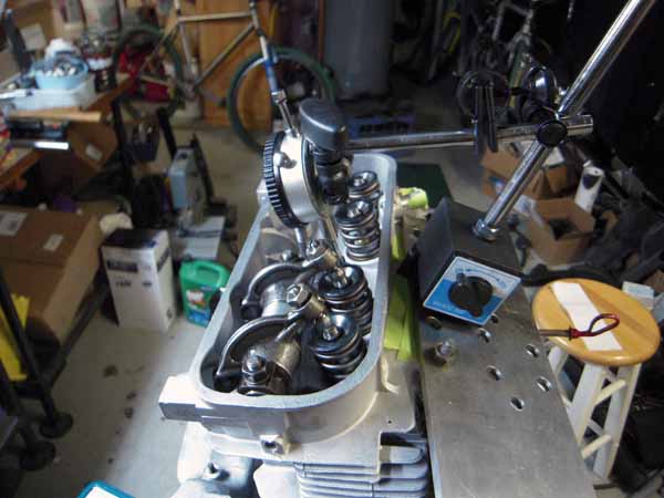
Chris nice job. I'm curious what your final push rod length was for intake and exhaust. Also, can you describe and/or photo how you mounted the dial indicator?
-- Rob
Posted by: Vacca Rabite May 3 2010, 07:10 AM
Chris nice job. I'm curious what your final push rod length was for intake and exhaust. Also, can you describe and/or photo how you mounted the dial indicator?
-- Rob
This information will not be helpful to anyone but the person that owns the engine. It is probable that each push rod is of a slightly different length. A 1/10 of an inch difference can be the difference of good geometry and bad geometry - the engine has to tell you what is right. That it why it is important to use the cut to length rods. Different cams, head spacers, case decking, etc all effect the eventual rod length.
The dial indicator can be mounted many different ways. It is important to be sure the the indicator is on the same plane of movement with the valve. I like to put the tip of the indicator on the retainer clip. Not a lot of space there, and some time it takes a few tries before you can find a spot that is on the correct plane, yet not interfereing with the actuation of the valve. improper placement will cause the indicator to be pushed off the valve, and even a small nudge will give an improper reading.
Zach
Posted by: watsonrx13 May 3 2010, 07:38 AM
Chris nice job. I'm curious what your final push rod length was for intake and exhaust. Also, can you describe and/or photo how you mounted the dial indicator?
-- Rob
This information will not be helpful to anyone but the person that owns the engine. It is probable that each push rod is of a slightly different length. A 1/10 of an inch difference can be the difference of good geometry and bad geometry - the engine has to tell you what is right. That it why it is important to use the cut to length rods. Different cams, head spacers, case decking, etc all effect the eventual rod length.
The dial indicator can be mounted many different ways. It is important to be sure the the indicator is on the same plane of movement with the valve. I like to put the tip of the indicator on the retainer clip. Not a lot of space there, and some time it takes a few tries before you can find a spot that is on the correct plane, yet not interfereing with the actuation of the valve. improper placement will cause the indicator to be pushed off the valve, and even a small nudge will give an improper reading.
Zach
Zach, I understand the differences between each engine, I was just curious about the difference between the pair of intake/exhaust rods on each piston because of the differences of the lifts. Also Jake mentions a min/max length for the rods.
Thanks for the description of the placement of the dial indicator tip.
-- Rob
Posted by: Cevan May 3 2010, 07:40 PM
Chris nice job. I'm curious what your final push rod length was for intake and exhaust. Also, can you describe and/or photo how you mounted the dial indicator?
-- Rob
Thanks. I'll post the final measurements. I'm only using .030 washers. Hopefully the real spacers will get here this week. Here's a photo of my setup.
Powered by Invision Power Board (http://www.invisionboard.com)
© Invision Power Services (http://www.invisionpower.com)