Printable Version of Topic
Click here to view this topic in its original format
914World.com _ 914World Garage _ Out with the old...in with the new...Britain's Racecar Development
Posted by: Britain Smith Dec 6 2010, 11:33 AM
For those who don't know me or the car, I have a '74 914 that is a dedicated AX car. It previously had a high compression 2.7 6-cylinder motor and made 205hp/205ft-lbs at the wheels. This set-up wasn't all that bad considering that it won the 2008 and 2009 914 Shootout events, however the quest for more speed continues.
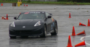
Here is the car in the 2010 season trim.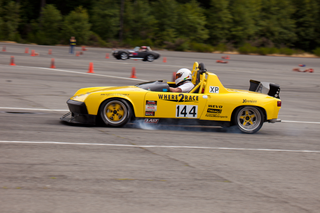
I have recently sold the 2.7L 6-cylinder engine and all the remaining 914/6 conversion parts. I have used the proceeds to fund the conversion to Subaru power. Now most would say that a Subaru conversion can be done on a budget, however I have found that the money goes flying out the window when doing something like this.
Regarding the engine...logical choice would be to go for a EJ257 2.5L USDM STi engine. However, all the SCCA rules for AX are built around displacement which in turn dictates the minimum weight. Therefore, I have gone with a JDM STi version8 Spec-C engine which is a 2.0L, twin-scroll, hand ported/polished, 8500rpm animal. I will get slightly less hp and torque numbers than the 2.5L, but save 150lbs of weight.
Posted by: Britain Smith Dec 6 2010, 11:33 AM
So, I have been working on the conversion for about a month now and have made significant progress. My goal is to have it running on the dyno by end of Jan. That will give me time to clean it up and complete some of the cosmetic items before the season starts.
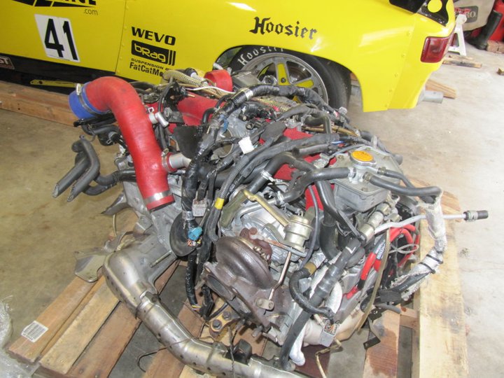
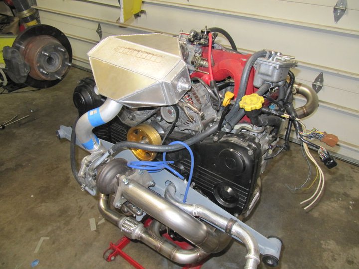
Here is the engine as it arrived: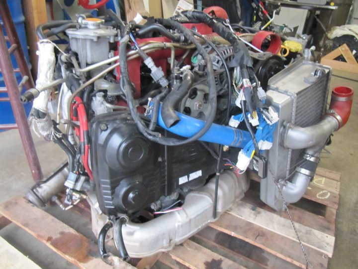
First thing I did was strip it down to the longblock and start cleaning things up. 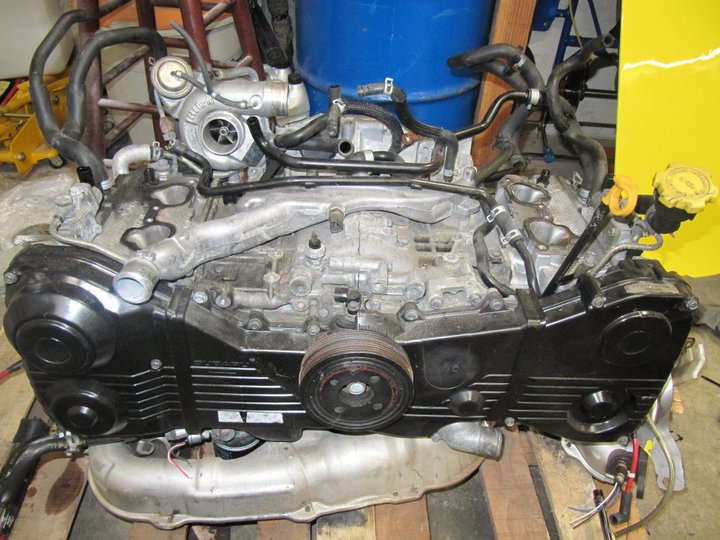
It is mated to the original Porsche 914 transmission with an adapter plate from Outfront Motorsports. Because I now have the Porsche bolt pattern, I could use my Porsche engine stand yoke...Bonus!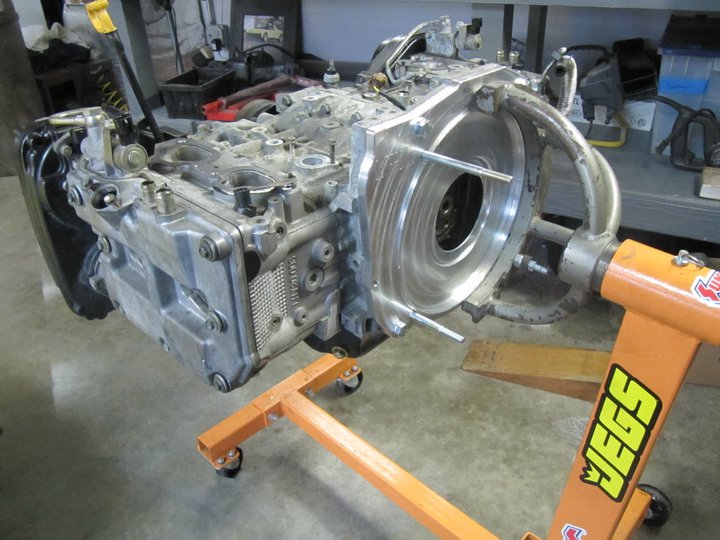
Here is a nice view...factory ported heads.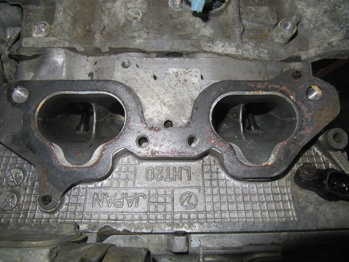
Ok, back to work...
I mounted a Outfront Motorsports alternator relocation kit to flip the alternator to the side. I also flipped the intake manifold as this is how it will fit into the car.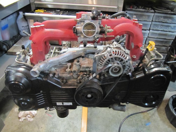
Now for the moment of truth...will it fit...more specifically, will it fit like I want it to. Here is the first stab into the chassis.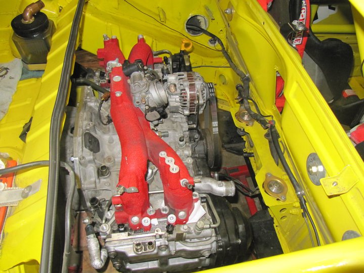
Posted by: Britain Smith Dec 6 2010, 11:33 AM
First thing I did was cut out the 914/6 bulkhead engine mount in front of the engine...you will see why I did this in just a bit. You can also see the nice stainless steel fuel lines that I installed here.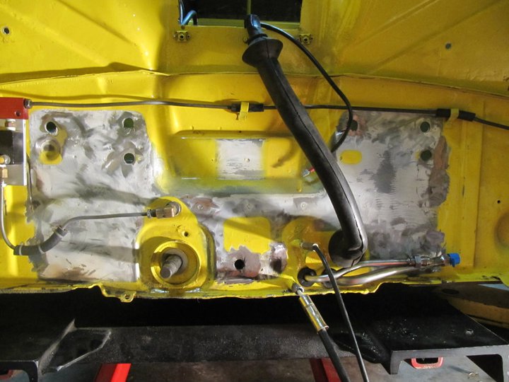
Back to the engine block. The JDM Spec-C came with an external oil cooler. This engine also had an additional sandwich plate for oil temp sensor. This stack was way too long and would put the oil filter at the lowest point of the car. 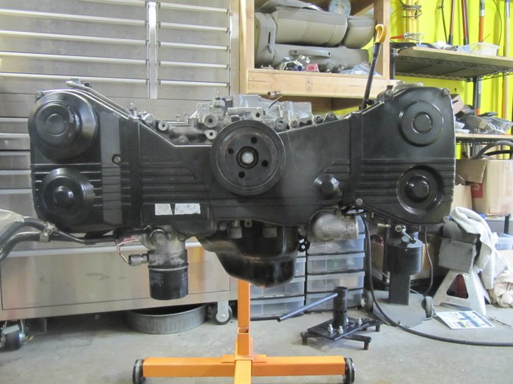
This is how long the oil filter mount bolt was to accommodate this length. I have since ordered and fitted a oil filter mount bolt from an N/A engine and it eliminate all the extra lenght so now I just have the oil filter mounted directly to the block.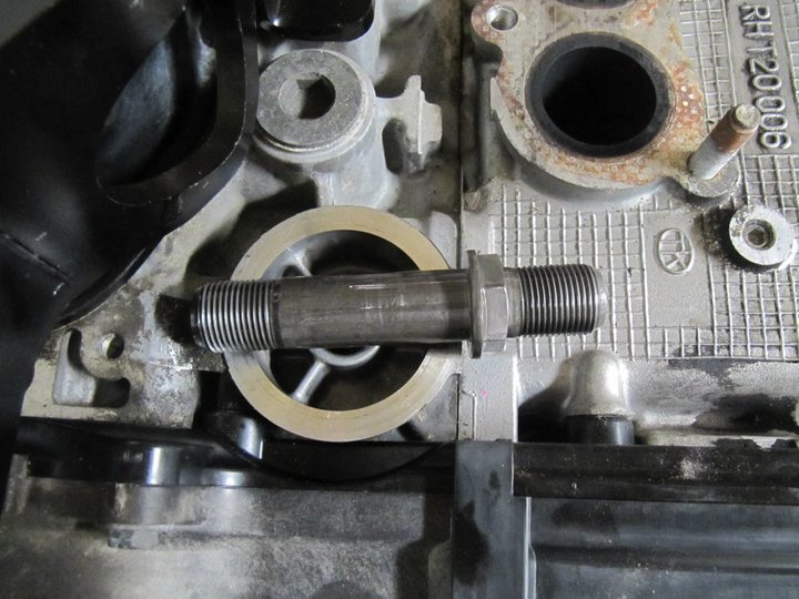
Posted by: Britain Smith Dec 6 2010, 11:34 AM
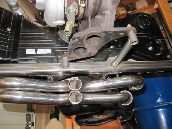
I purchased the Synic Motorsports header which is equal lenght, but not exactly for a twin-scroll set-up. 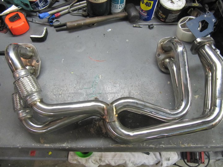
With the header installed on the engine, you can see the engine mounts that I am utilizing for the conversion. They are actually for a Vanagon conversion, but with a little modification they fit just fine.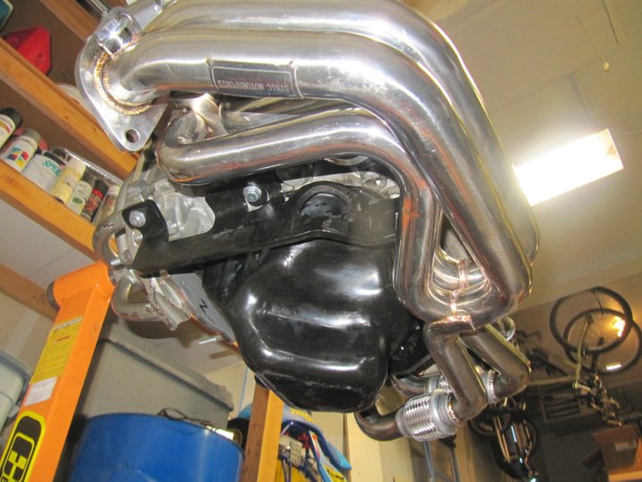
Back to the header...the first order of business was chopping off the pipes right after the merge collectors...getting closer to a twin-scroll set-up.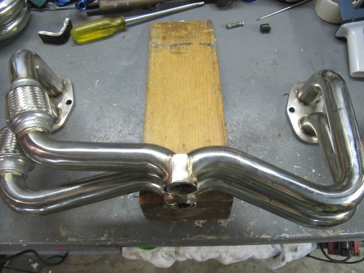
The only problem was that when I cut off the pipes, I was faced with a failed attempt at properly building a header. The merge collectors were not the highest quality that I have seen.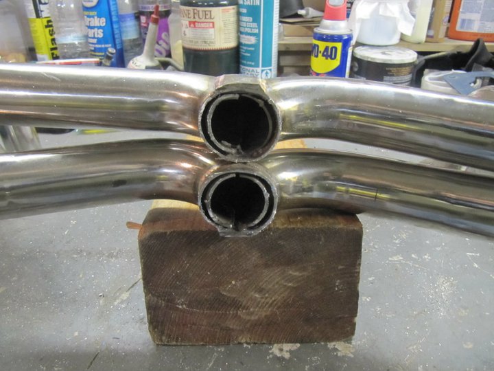
Little bit of time with the die grinder and they look much more acceptable now...and I bet the flow better.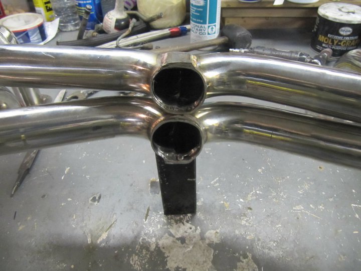
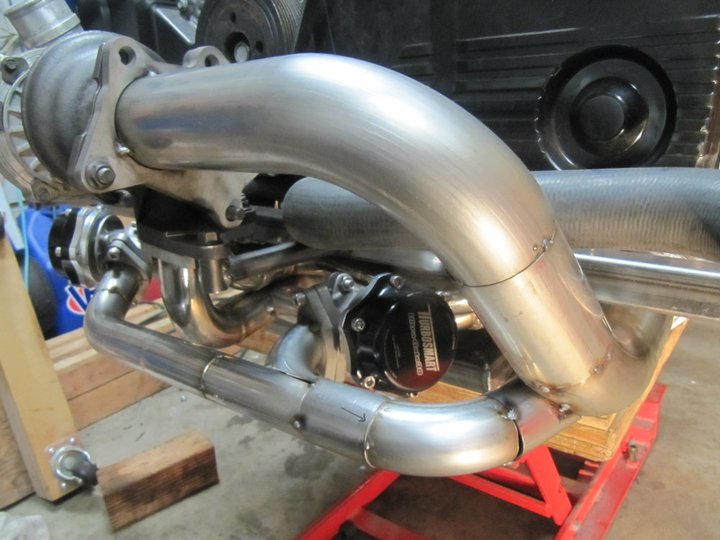
Ok, now with the header mounted you can see my thinking on the positioning of the turbo.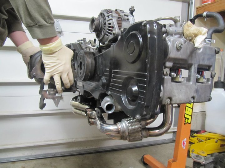
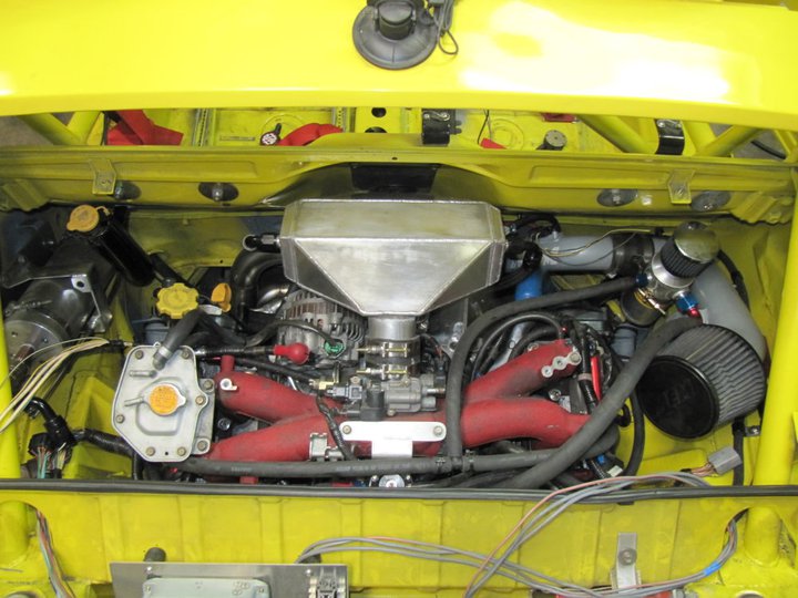
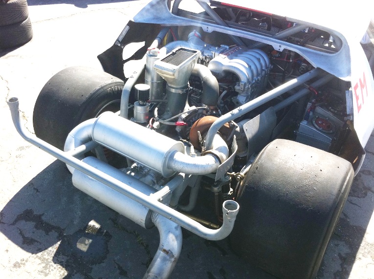
With the engine back in the car and everyone suspended with straps, you can see how the turbo will fit just perfectly in the factory recessed firewall location. 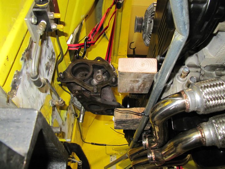
To get the turbo in the correct orientation, I had to re-clock the compressor side. To do this, I took off the small retaining bolts/clips, applied a little heat and some motivation from a mallet and it popped right off.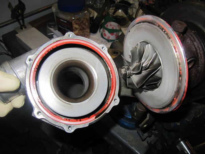
Posted by: Britain Smith Dec 6 2010, 11:36 AM
Now that I have an idea where the turbo will fit and how the headers route around the engine, I could fab up the engine mount bar. The bar attaches to the Vanagon mount that I showed earlier and extends to the frame rails. At the frame rails, there are rubber bushings. Here is the engine suspended in the car for the first time.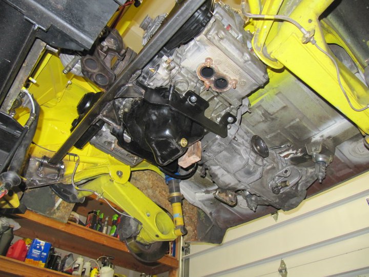
Now I just have to connect the dots between the exhaust ports and the turbo...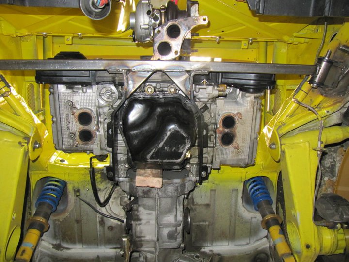
Here is the turbo hard mounted to the engine mount bar. I had two threaded bungs machined that the turbos mounts to.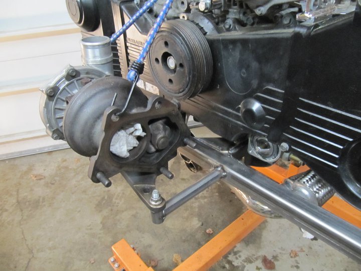
I found it difficult to source JDM uppipe and downpipe flanges for my use, therefore I just had them waterjet at a place down the street. I am running external wastegates so the internal wastegate port was blocked off. They turned out fantastic and if anyone needs a pair, just let me know and I can get them cut for you. 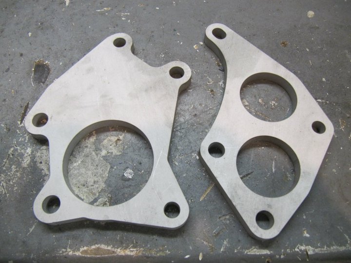
Using left over piping that I had cut off the header, I fab'ed up the connecting pieces for the header to the turbo. 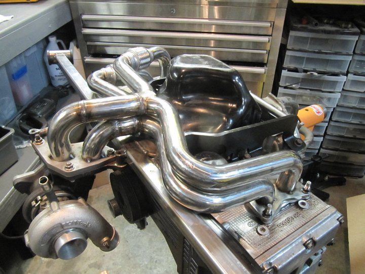
Here it is mounted in the car...everything fits like a glove.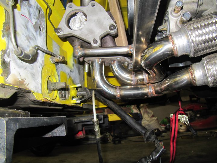
With the turbo mounted in this location, the gravity drain has no where to go to get back to the oil pan. I was very restricted on space, so I had to fab up a custom drain pipe using the oil coolant hard lines off the engine.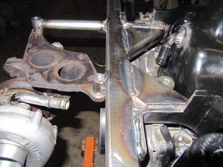
It is all downhill back to the oil pan...just barely.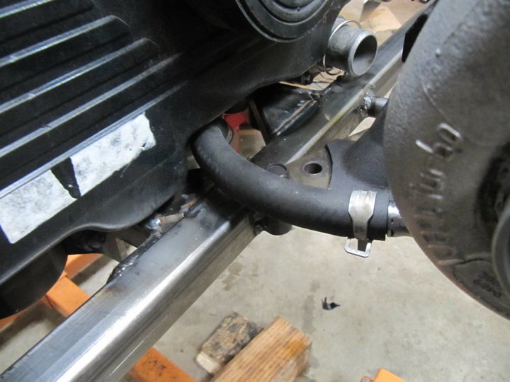
Posted by: Britain Smith Dec 6 2010, 11:36 AM
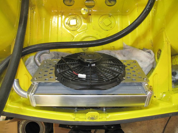
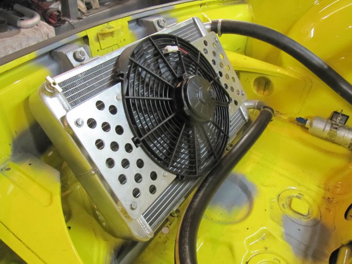
With the engine mounted, it was time to address some necessary items on the chassis. First off was the radiator. Here is my first mock-up of the radiator location. This one is 16x22, however I went with a 14x22 to add some additional clearance. It will mounted it at about a 30deg angle in the front trunk and vent it out the hood. It will also have a Spal fan mounted to help with cooling while sitting in the pits between runs.
My tiny 5 gallon fuel tank is just not going to fit properly and I will probably have to make a new one that is narrower and wider.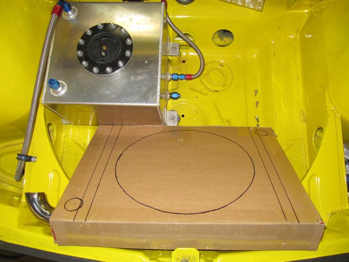
The radiator lines are Gates Yellow-Strip hose snaked throughout the body. In the front, I opened up some of the body panels and run the lines thru.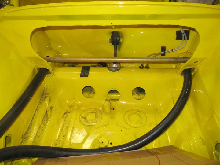
In the cabin, the lines jog over to the frame rails and down what used to be the heater ducting tubes.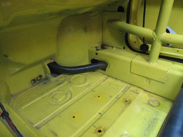
In the engine bay, they come out of the heater duct tubes and will connect to the engine.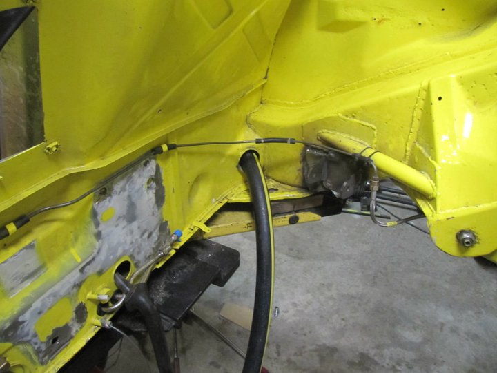
One issue with the engine mount bar that I fabricated was the clearance for the thermostat housing cover. 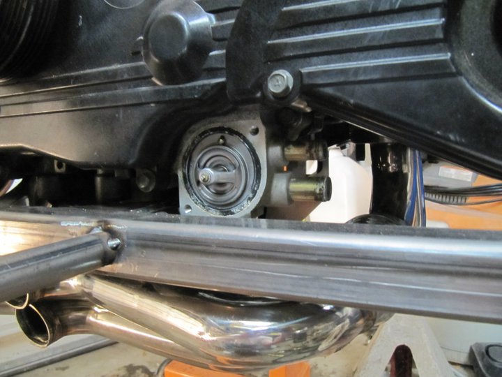
After a little sleuthing around ebay, I decided to take a chance on a Subaru 3.0L engine thermostat housing which was for sale for pretty cheap. Here you can see the differences.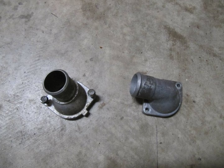
Low and behold, it fits and gives me just enough clearance...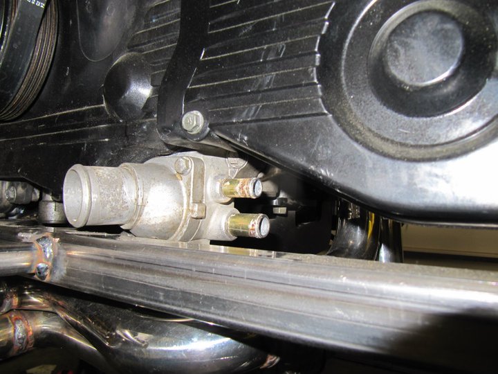
Posted by: Britain Smith Dec 6 2010, 11:37 AM
While waiting on more parts, I decided to start tackling the wiring nightmare. Unlike a lot of swaps on here, I have no WRX to compare to. Nor was I able to initially locate the proper wiring diagrams. Therefore, I started by mapping out the entire engine harness. This should be all the wires that I need to make it run.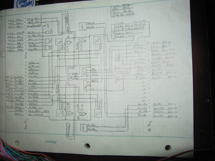
Here is my daughter lending me a hand.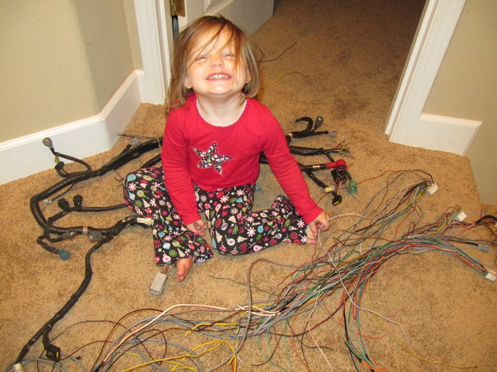
Here is the harness about 90% done. I have a few more issues to work out in regards to main power and ignition power, but it is basically ready. I will clean all of this up and make it look nice and pretty after the engine is running.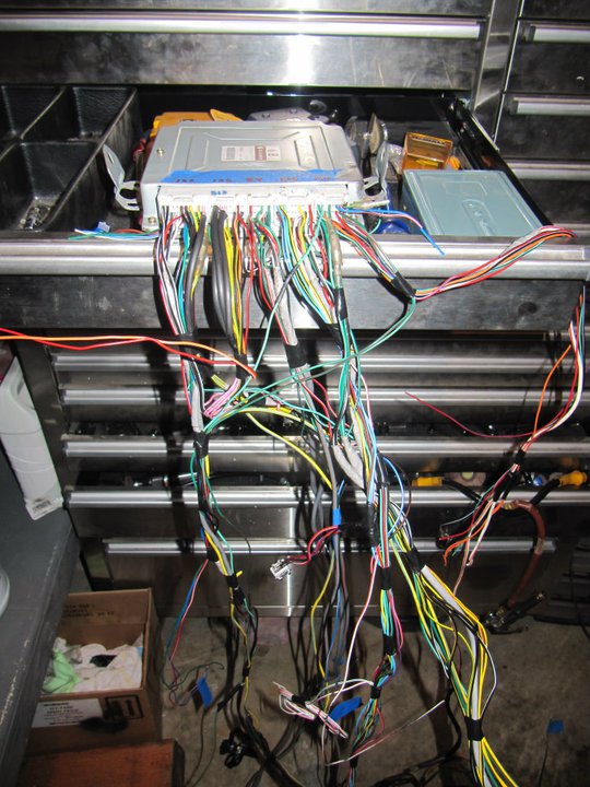
Here is the engine with the harness back installed and just about completed. 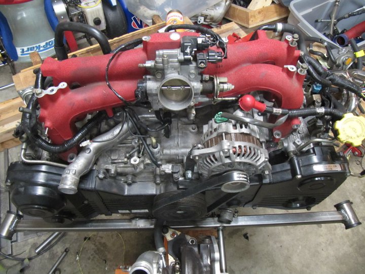
Posted by: Britain Smith Dec 6 2010, 11:38 AM
The beautiful pair of Turbosmart wastegates, Turbosmart Blow-off Valve, and Turbosmart Fuel Pressure Regulator...pure works of art.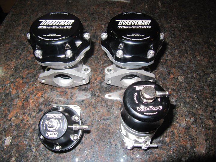
Posted by: Britain Smith Dec 6 2010, 11:38 AM
From this weekend.
First order of business was rerouting the water coolant lines coming off the waterpump housing. The Outfront Motorsports bracket interferes with the stock routing of the heater hardline and the line that goes to the coolant reservoir tank was pointing in the wrong direction after it was relocated. Therefore I got some extra hardlines and starting cutting and welding away.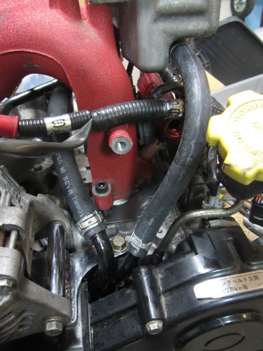
Here is the pipe off the back of the water cross-over pipe. I am obviously bypassing the heater core but that line was interfering with the bulkhead.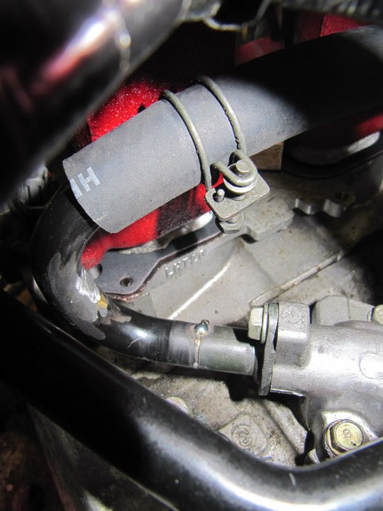
Fab'ed up a small bracket to secure the Turbosmart FPR to the intake manifold. Had to order some additional AN fittings for the fuel line routing $$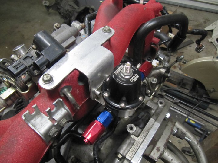
Finally got started on the exhaust downpipe routing. Here is the front section, however I still have to stuff two wastegates in here.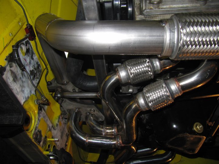
Here is the routing down the length of the car. You can also see the bracket I made to secure the Coast Fabrication Muffler.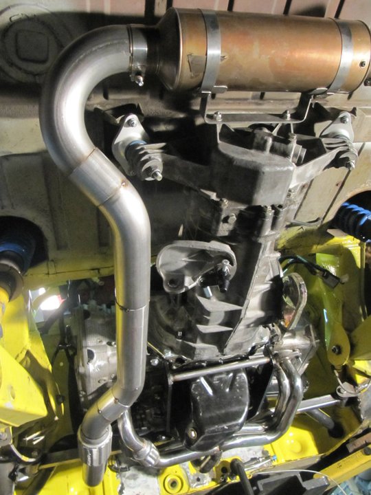
This muffler weighs less than 5lbs. This one was scuffed a bit so I got it less than half off...gotta love the scratch and dent sales. I sure hope it is quiet enough to pass sound regulations...if not, I might be adding another.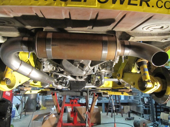
Got to get some additional flanges cut at the waterjet place today and then I can finish up the wastegate routing.
-Britain
Posted by: Britain Smith Dec 6 2010, 11:42 AM
Well, that is about a month worth of effort...time goes by quick when you are doing this sort of stuff.
-Britain
Posted by: JmuRiz Dec 6 2010, 11:44 AM
Looks like a lot of work, I'm sure it'll be a rocket seeing the motor you got rid of to upgrade to this!
Posted by: Britain Smith Dec 6 2010, 11:45 AM

Looks like a lot of work, I'm sure it'll be a rocket seeing the motor you got rid of to upgrade to this!
Yea, I hope I choose the right path. The car might actually end up slightly lighter with this set-up.
-Britain
Posted by: McMark Dec 6 2010, 03:30 PM
So awesome! Everything looks really great!
Posted by: Cupomeat Dec 6 2010, 03:34 PM
VERY nice, Installs like this make me want to consider a Porscharu conversion.
Can't wait to see more! ![popcorn[1].gif](style_emoticons/default/popcorn[1].gif)
Posted by: URY914 Dec 6 2010, 05:46 PM
Nice work. Go to see someone doing something different.
Posted by: McMark Dec 6 2010, 05:49 PM
Why two wastegates? Staged?
Posted by: Britain Smith Dec 6 2010, 06:04 PM
Because it is a twin-scroll turbo. If you merge the two headers for a single wastegate then the benefits of twin-scroll in terms of exhaust pulses is lost.
-Britain
Posted by: Rand Dec 6 2010, 06:59 PM
Nice work Brit! Can't wait to hear your impressions after racing it.
Posted by: McMark Dec 6 2010, 07:57 PM
Apparently I have some Googling to do tonight....

Posted by: 396 Dec 7 2010, 12:01 AM
Very very nice! I can only wish I had the skills to do what you've just accomplished!
Once done..your going to kick some A with that set up:)
Congrats and good luck!
Posted by: diggatron Dec 7 2010, 01:40 PM
Can I ask where one might be able to get this Vanagon Engine mount?
With the header installed on the engine, you can see the engine mounts that I am utilizing for the conversion. They are actually for a Vanagon conversion, but with a little modification they fit just fine.
Posted by: forcefed Dec 7 2010, 02:13 PM
Allow me to make a suggestion,
You have the turbo hard mounted to the engine bar. Your gonna want to make the exaust tubes going to the turbo flange a "Slip fit" (one tube slides inside the other). You have a perfect space on the straight for it. From my experiance I can guarentee that if that is stainless tube, you could be chasing cracks everywhere in the header. Stainless moves so much when it gets hot. With a hard mount there is no where for it to expand. btw Excelent choice with the coast fab muffler, the best out there by far. With the turbo and the muffler, it should be quiet enough.
Posted by: forcefed Dec 7 2010, 02:29 PM
instead of a slip fit , you could add two more bellows, or you can get rid of all your bellows all together and make them all slip fit.
Posted by: Borderline Dec 7 2010, 02:36 PM
WOW! That looks great! It's hard to imagine you being so much faster than you were at the Shootout. Are you going to go larger with the rear tires to handle the new power or do you think the existing setup will handle it? Your work is amazing! Good luck!
Posted by: Britain Smith Dec 7 2010, 02:47 PM
The Vanagon Engine mount came from http://www.smallcar.com/index.php?dispatch=products.view&product_id=29789.
-Britain
Posted by: ONTHEGRIND Dec 7 2010, 02:59 PM
If you ever yank the heads or need coatings let me know I'd like to run a sticker on that car...
Posted by: Britain Smith Dec 7 2010, 03:28 PM
Thanks for the offer...hopefully I won't have to do anything to the motor itself. I will know in Jan.
-Britain
Posted by: jpnovak Dec 7 2010, 03:34 PM
Britain,
You have made fantastic progress! I am impressed.
I would like more information on the alternator bracket. i have yet to relocate mine but that will be soon.
Posted by: Britain Smith Dec 7 2010, 03:53 PM
Got the Alternator Relocation bracket from Outfront Motorsports. It isn't listed on their site, you have to call them for it.
-Britain
Posted by: bandjoey Dec 7 2010, 04:04 PM
Where does the AC compressor go? (just kidding  )
)
what a lot of work. What a professional looking job. 
If you compare this conversion against your old flat 6 which one is harder - easier and cheaper - more expensive?
Great work and enjoying the build pictures.
Posted by: Cheapsnake Dec 7 2010, 04:09 PM
VERY nicely done. I especially appreciate your routing of the hoses through the cockpit. It solves a lot of problems.
Tom
Posted by: andys Dec 7 2010, 04:17 PM
instead of a slip fit , you could add two more bellows, or you can get rid of all your bellows all together and make them all slip fit.
+1 for the two additional bellows. They'll help alleviate issues with not only expansion/contraction of the header, but also any shift in the turbo location due to slight motor mounting shifts (between routine removal/install); though my personal preference would be to anchor the turbo to the motor.
Nice work!
Andys
Posted by: DanT Dec 7 2010, 05:40 PM
Brit, the transformation to Porscharu is going nicely...
anxious to hear your impressions after it is all buttoned up and sorted out.
Posted by: d914 Dec 7 2010, 05:40 PM
your making me look bad... all that work in a short time.. NICE job..
Posted by: Britain Smith Dec 7 2010, 06:00 PM
your making me look bad... all that work in a short time.. NICE job..
I have a schedule...gotta be ready to sort out the car by the beginning of the season if I want to be competitive at nationals.
-Britain
Posted by: Britain Smith Dec 7 2010, 06:01 PM
Brit, the transformation to Porscharu is going nicely...
anxious to hear your impressions after it is all buttoned up and sorted out.
I am going to try to make the event at Medford with everyone...that track was a lot of fun. When I went down there in August I set the track record for EM by 10secs and I ran outta gear halfway down the straightaway

-Britain
Posted by: J P Stein Dec 7 2010, 06:52 PM
If you compare this conversion against your old flat 6 which one is harder - easier and cheaper - more expensive?
At this point...he's not done spending, but close......it's about a zero sum swap moneywise. All that old stuff sold quickly for about .50 cents on the dollar.....you do the math
The degree of difficulty would seem a toss up, me thinks.
He's making it tougher on himself by compressimg the time frame needed to do the work. That said, he's doin' gud.
God help him if he sets it up & ready to go racing by Feb 1-15. "Stuff" (including the weather) don't get rolling up this way till the middle of March at best.....he'll go nutso.
Posted by: r_towle Dec 7 2010, 07:28 PM
If you compare this conversion against your old flat 6 which one is harder - easier and cheaper - more expensive?
At this point...he's not done spending, but close......it's about a zero sum swap moneywise. All that old stuff sold quickly for about .50 cents on the dollar.....you do the math
The degree of difficulty would seem a toss up, me thinks.
He's making it tougher on himself by compressimg the time frame needed to do the work. That said, he's doin' gud.
God help him if he sets it up & ready to go racing by Feb 1-15. "Stuff" (including the weather) don't get rolling up this way till the middle of March at best.....he'll go nutso.
Cheer him on..I got that.
Still must be somewhat sad to watch your baby be taken apart.
Rich
Posted by: Britain Smith Dec 7 2010, 09:48 PM
JP has been involved every step of the way...in fact, he is the one who pushed me off the cliff.
-Britain
Posted by: DanT Dec 7 2010, 09:53 PM
I kind of thought JP might be in the middle of this
He would love nothing better than to get this car to the top of the SCCA national heap.
Posted by: bandjoey Dec 7 2010, 09:58 PM
Ah...now I understand. JP's motto...Bigger and Faster is Always Better
Posted by: Britain Smith Dec 7 2010, 10:12 PM
It is actually smaller...engine displacement speaking.
-Britain
Posted by: Britain Smith Dec 7 2010, 10:12 PM
I kind of thought JP might be in the middle of this
He would love nothing better than to get this car to the top of the SCCA national heap.
It is my car now and I agree, I would love to get the car to the top of the SCCA National heap.
-Britain
Posted by: diggatron Dec 7 2010, 10:13 PM
The Vanagon Engine mount came from http://www.smallcar.com/index.php?dispatch=products.view&product_id=29789.
-Britain
Thanks, Britain! I haven't picked my '14 up yet, but that will happen this week... Just making the rest of the plans!
Posted by: Britain Smith Dec 7 2010, 10:16 PM
Another thing to consider from them is their vehicle speed sensor. I have found that my engine ECU requires a vehicle speed sensor for the active valve time to function. I ordered mine today.
-Britain
Posted by: DanT Dec 7 2010, 10:33 PM
I kind of thought JP might be in the middle of this
He would love nothing better than to get this car to the top of the SCCA national heap.
It is my car now and I agree, I would love to get the car to the top of the SCCA National heap.
-Britain
Yes I know that, I should have said HELP you get it to the top of the SCCA heap
Posted by: ChrisNPDrider Dec 7 2010, 11:58 PM
What, no yellow? That intake would look good in yellow.

Posted by: Britain Smith Dec 8 2010, 12:47 AM
What, no yellow? That intake would look good in yellow.
Ha...I was actually thinking about painting the timing belt covers in yellow.
-Britain
Posted by: dlo914 Dec 8 2010, 12:50 AM
The Vanagon Engine mount came from http://www.smallcar.com/index.php?dispatch=products.view&product_id=29789.
-Britain
Thanks, Britain! I haven't picked my '14 up yet, but that will happen this week... Just making the rest of the plans!
Brit, how much were the brackets?
Posted by: J P Stein Dec 8 2010, 07:03 AM
Still must be somewhat sad to watch your baby be taken apart.
Rich
I was kinda burnt out on it. What Brit is doing is pretty much what I would have done and he is better equipped to do so on many levels.....which means he's as much of a lunatic as I ever was.
Dan:
The car needs some serious mods to the front end to get more tire up front.
"The Kid" has plans for that but it is another project that will be a serious time/money eater.
Posted by: Britain Smith Dec 8 2010, 11:42 AM
Brit, how much were the brackets?
You can get the whole bracket kit for $249 which includes a crossbar that is built to bolt to a Vanagon. However, I later found out that you can purchase just the two brackets that bolt to the engine block for ~$190. Give them a call, they can hook you up with what you need.
-Britain
Posted by: BMXerror Dec 8 2010, 01:50 PM
Great work, Britain!  I'm amazed that you're doing so much, so quickly. And it looks like quality sh*t too! Where do you find that kind of time? Keep it up.
And if you decide to come back down to San Diego this year, let me know. I'll come out and crew for you. Go get 'em, bud.
Mark D.
Posted by: jjackson Dec 9 2010, 06:52 AM
Impressive work in such a short period of time.Look forward to seeing car run at '11 nationals.Good luck with the sorting.Small turnout of 914s last year.
Posted by: Britain Smith Dec 10 2010, 02:14 PM
Few updates. Took a few days off work to make some progress before the holiday season gets underway. I also got a lot of parts in and I couldn't wait to get them mounted.
First off was to mount the pair of Turbosmart wastegates and finish the exhaust plumbing. Here you can see the general location of all the components.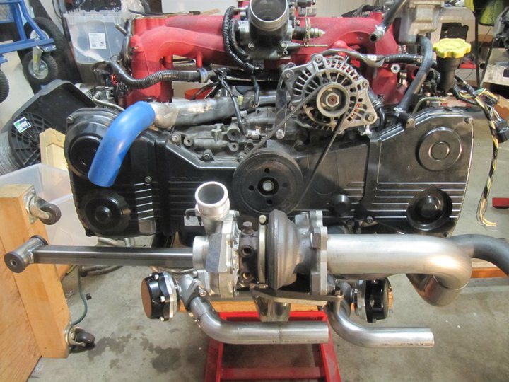
Both wastegates will dump back into the exhaust stream so that I can control the output noise levels due to sound restrictions at some venues. Both wastegate dumps are 1.5" and then merge into 1.75" before being dumped into the exhaust. After several hours of fab work with a "metal master" buddy of mine, it was all completed. Just have to get it professionally tig welded to call it done.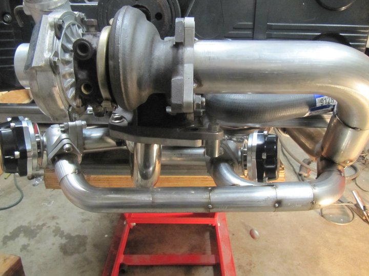
Here it is mounted in the car to ensure that everything clears and fits in its respective location.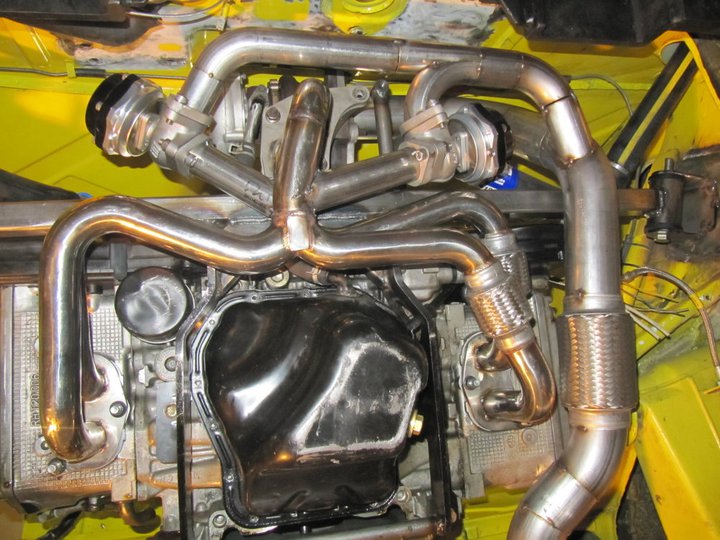
The location of the turbo and the mess of the header and exhaust plumbing has made it impossible to run the stock shifter bar. Therefore, I have adapted parts of a cable shift set-up to handle the shifted duties. If you remember, I only have 2 gears in my transmission and therefore only need to shift forward and back...pretty simple. Here is the transmission side.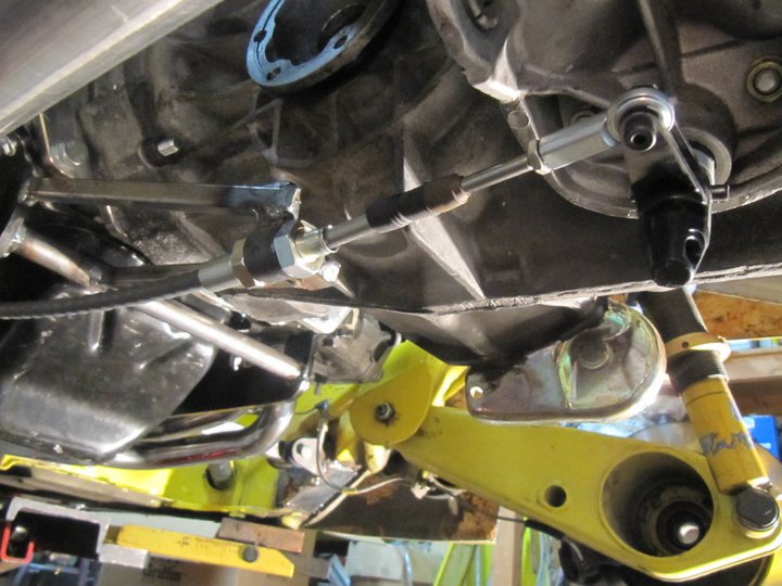
Posted by: Britain Smith Dec 10 2010, 02:15 PM
Because this engine is "special" and has the TGV delete manifold, the Aeromotive fuel rails interfer with the AVSC solenoids (blue plug). 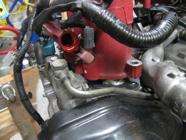
However, by spacing the intake manifold up ~16mm I was able to clear the plug. I order a set of 16mm phenolic spacers from KSTech and everything clears like it should.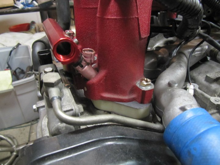
The second problem with the Aeromotive fuel rails are the mounting brackets. Again, because they are supposed to be mounted to a TGV they don't fit my Spec-C manifold. Therefore I had to fab up a pair of brackets to secure them. Here you can see the difference between the new brackets and the ones that came with the kit.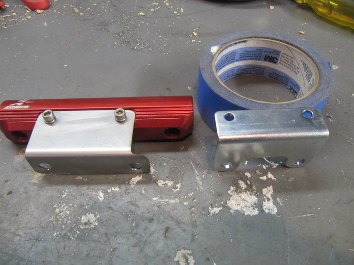
Here they are on the engine...all good.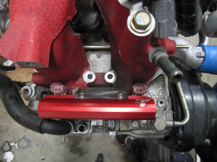
Posted by: Britain Smith Dec 10 2010, 02:15 PM
I usually don't like to show new parts until they are installed, but I had to show off the custom Griffen radiator I got in yesterday. It is going to fit perfectly.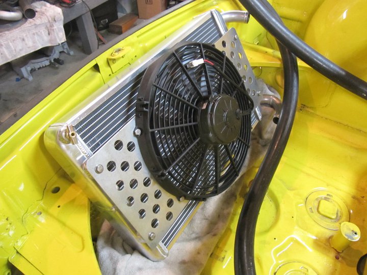
I also got in the ice box from Frozenboost.com. If you get to take a ride, this will be between your legs. Maybe I can hook up a "cool" suit for that hot days...hmmmm.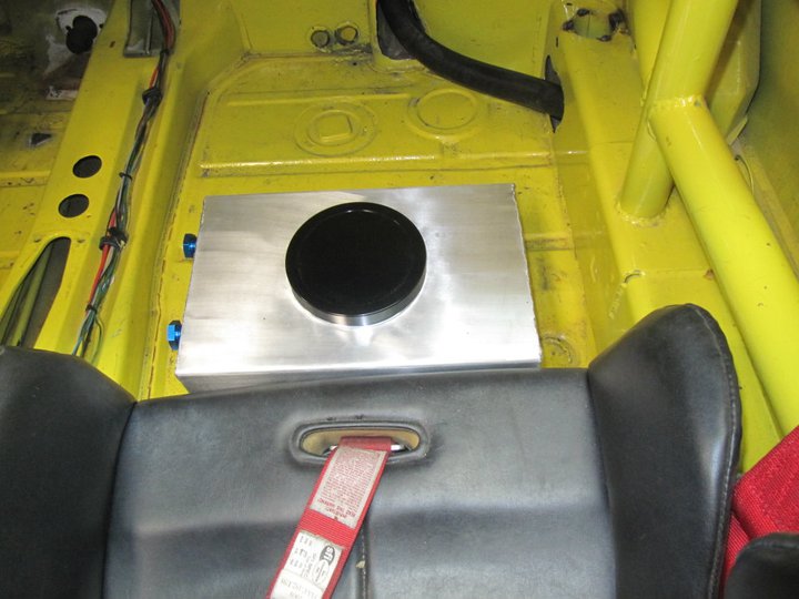
Ok, back to the garage to continue working.
Posted by: ottox914 Dec 10 2010, 10:19 PM
Awesome.
Posted by: GS Guy Dec 11 2010, 07:39 AM
Looks great! Interesting how everybody has a slightly different take and process on fitting the Subaru engine. That header is wild!
How did you go about spec.-ing the radiator with Griffin? I notice it has unusually narrow end tanks - I guess to provide more core room? Did you make a model and sent them, or just sketches? I'll be going through the same process soon.
Jeff
Posted by: WLD419 Dec 11 2010, 08:53 AM
Dude , You have some serious Planning & Fabbing Skills ,Wow !
truly asome ,
Bill D.
Posted by: cary Dec 12 2010, 10:10 AM
Looks like your having fun.
Let me know if you need an extra set of hands.
I'm putting the finishing touches on the shop. Plumbing in the compressor air lines overhead. Driving by about every other day.
Just about ready to start working on my daily driver. Oh yeah, I did buy an enclosed trailer. 20ft. Haulmark. TTYL.
Posted by: ottox914 Dec 12 2010, 02:52 PM
You have probably researched this and thought it thru already, but since you are in the install/set-up/plumbing phase, how about preping for E85 and getting a hot tune for that corn hooch. I'd bet 400hp easy.
Posted by: J P Stein Dec 12 2010, 04:38 PM
You have probably researched this and thought it thru already, but since you are in the install/set-up/plumbing phase, how about preping for E85 and getting a hot tune for that corn hooch. I'd bet 400hp easy.
It has been discussed. Brit is taking a conservative approach by waiting to see what breaks. The 901 is still there....tho first gear is safe cause it's in a cardboard box. As for the R&P......

Posted by: Britain Smith Dec 12 2010, 07:02 PM
You have probably researched this and thought it thru already, but since you are in the install/set-up/plumbing phase, how about preping for E85 and getting a hot tune for that corn hooch. I'd bet 400hp easy.
The fuel system is prep'ed for E85, however I am going to continue using my 110octane leaded fuel for the time being. It will give the same performace gains and I have ~30gallons left over from last season. Not going to get 400hp, but hopefully close.
-Britain
Posted by: charliew Dec 13 2010, 11:13 AM
Another thing to consider from them is their vehicle speed sensor. I have found that my engine ECU requires a vehicle speed sensor for the active valve time to function. I ordered mine today.
-Britain
My son has been hotrodding his 04 sti since he got it new. He's a mechanical Engineer with our hotrodding exposure from my and his toys. We aren't track guys though. I started with a new 02 wrx motor in a 901 tail dragger dunebuggy but decided the 914 was a better way to go. I have been planning and scrounging parts for a long time and soon may get to start the real deal. When I studied the smartcar vss a few years ago I bought one but my understanding it is only to make sure the car is in motion, it will not replace the speedo feedback. I guess you know what you are talking about on needing the two waste gates. My thought is the inlet side using two waste gates might reduce the surge of the turbo better but the pulses from each exhaust port would seem to me be better controlled after the turbo wheel rather than before to get the quickest spool time. You are doing great though and will be a very valuable source on what works at high rpm in the 914 high g suby configuration. The suby uses more oil than you will think at high rpm and high oil temps so monitor it very carefully. Now that the twin scroll exhaust is removed I would tackle the oil pan and try to get as much more capacity as you can. The oil pickup is a very critical spec on the suby motor, there is a lot of variation in the oil pan tp pickup clearance. The external oil cooler is really necessary, get a oil temp sender and good gauge. The good thing is it's a race car and you can change over heated oil pretty regularly. You also may have considered a turbo blanket I hope. Are you going to learn to do open source programming on the oem ecu also? I am anxious to see if your radiator is going to be big enough. If the boost is laggy you might want to check the exhaust back pressure at the turbo. The exhaust on my son's sti is at least 3.0 all the way with straight through muffler and no cat. Your exhaust is shorter though. I do wish you had gone with the suby tranny also.
Posted by: Britain Smith Dec 13 2010, 11:40 AM
When I studied the smartcar vss a few years ago I bought one but my understanding it is only to make sure the car is in motion, it will not replace the speedo feedback.
Yea, that is my thought as well. However, using the Small Car Performance speedo sensor kit I should be able to get relative speed numbers and I can feed that into my AIM dash for datalogging.
I guess you know what you are talking about on needing the two waste gates. My thought is the inlet side using two waste gates might reduce the surge of the turbo better but the pulses from each exhaust port would seem to me be better controlled after the turbo wheel rather than before to get the quickest spool time.
The wastegates go before the turbo and the blow-off valve goes after the turbo. I need two wastegates because I have cylinders 1 & 3 and 2 & 4 entering the turbo separately (twin-scroll) and the two wastegates will keep the exhaust pulses independent. Wastegates control the amount of exhaust gases that go to the turbo and therefore control the boost pressure. The blow-off value is between the turbo and the throttle body to reduce surge of the turbo when the throttle is closes...the pressurize air needs somewhere to go.
You are doing great though and will be a very valuable source on what works at high rpm in the 914 high g suby configuration. The suby uses more oil than you will think at high rpm and high oil temps so monitor it very carefully. Now that the twin scroll exhaust is removed I would tackle the oil pan and try to get as much more capacity as you can. The oil pickup is a very critical spec on the suby motor, there is a lot of variation in the oil pan tp pickup clearance. The external oil cooler is really necessary, get a oil temp sender and good gauge. The good thing is it's a race car and you can change over heated oil pretty regularly.
Yes, I am also concerned about oil pick-up under the conditions that I run. I have an Accusump plumbed in and will be address the oil pan after the engine is running on the dyno.
You also may have considered a turbo blanket I hope. Are you going to learn to do open source programming on the oem ecu also? I am anxious to see if your radiator is going to be big enough. If the boost is laggy you might want to check the exhaust back pressure at the turbo. The exhaust on my son's sti is at least 3.0 all the way with straight through muffler and no cat. Your exhaust is shorter though. I do wish you had gone with the suby tranny also.
Yes, I have considered a turbo blanket or heat shield...we shall see how things go on the dyno.
Yes, I am using Open Source tuning...however this will be done at Cobb Tuning.
The exhaust is 2.5" all the way back and with the smaller turbo, it should be fine.
I might be changing to a different trans, we shall see how long the 901 lasts.
-Britain
Posted by: charliew Dec 13 2010, 12:21 PM
When the vss was sold to me I think I remember it gives way less pulses than the suby tranny. It's not enough to run a electric speedo so my thinking was it won't run the ecu for any more than fail safe limp home avoidance.
I wouldn't start the motor without veryfying a good pickup clearance if it was mine.
My son uses open source also and I am planning on his support on mine but it isn't going to be avcs although we do have his original low miles 04 sti motor complete in my garage.
My understanding of twin scroll is the ports were put in the tubes to keep the velocity up and the pulses smoother. Smaller tubes is more velocity and putting the ports in the tubes that way means smooth pulses. We will see, thats the good thing about hot rodding and all the good ideas. I personally like to keep it as simple as possible to eliminate things breaking.
Posted by: Britain Smith Dec 15 2010, 12:39 PM
Couple of updates while the engine is out a shop getting all the exhaust tig welded.
Some of you might have noticed in the previous picture of the radiator that the fan was mounted about an inch from the radiator. Not sure why they built it that way, but I modified the fan mounts to move it about 1/4" from the radiator. This will be much more efficient. I also had some tabs welded on for the mounts to the chassis.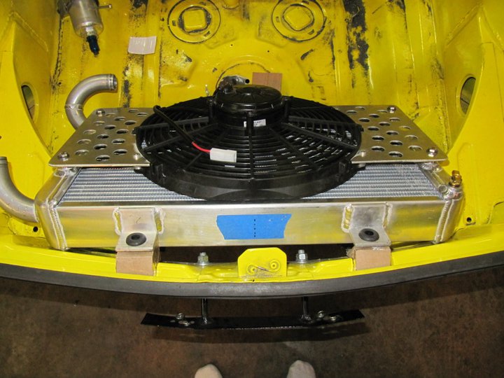
Also made a bracket to hold the three master cylinder reservoirs in the front. I am mounting a Tilton brake pedal assembly and converting the clutch to a hydraulic throw-out bearing hence the need for this set-up.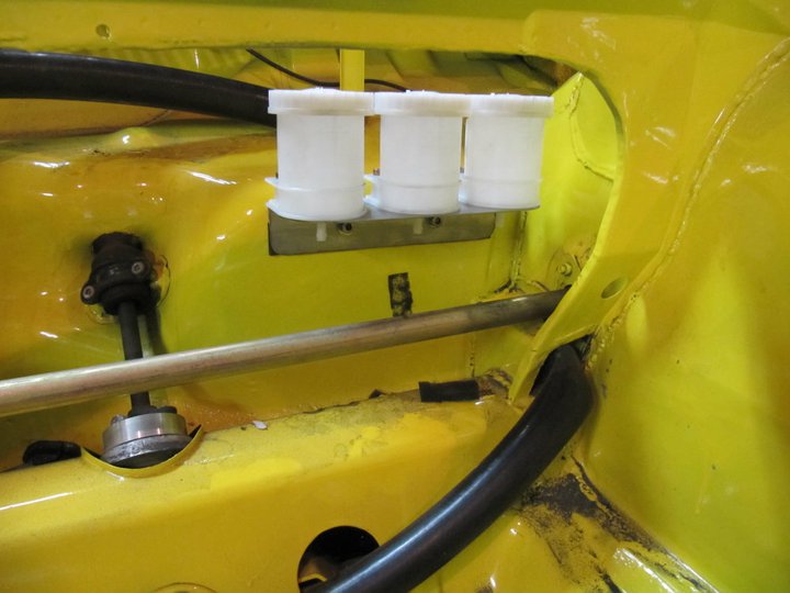
-Britain
Posted by: Britain Smith Dec 18 2010, 11:02 PM
Made a lot of progress today. It is always nice to start bolting things back up to the car.
To mount the radiator, I had tabs welded on the core and made some nice brackets that I welded into the car. Here are the brackets: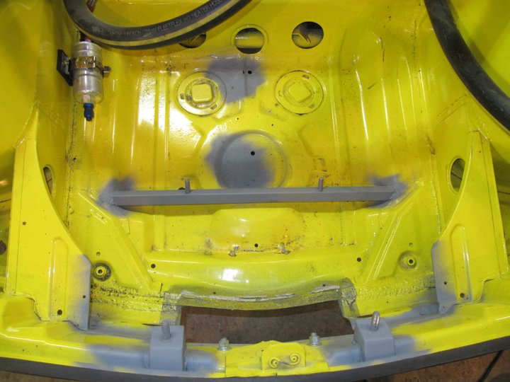
And with the radiator installed and radiator hoses hooked up.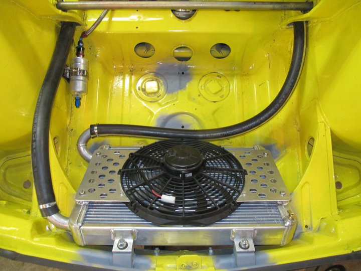
I made the bottom radiator support elevated off the floor to ensure that if the car bottomed out or the floorboard got dented then it wouldn't destroy the radiator. The center section of the mount bar was notched to clear the tow hook hump in the sheetmetal.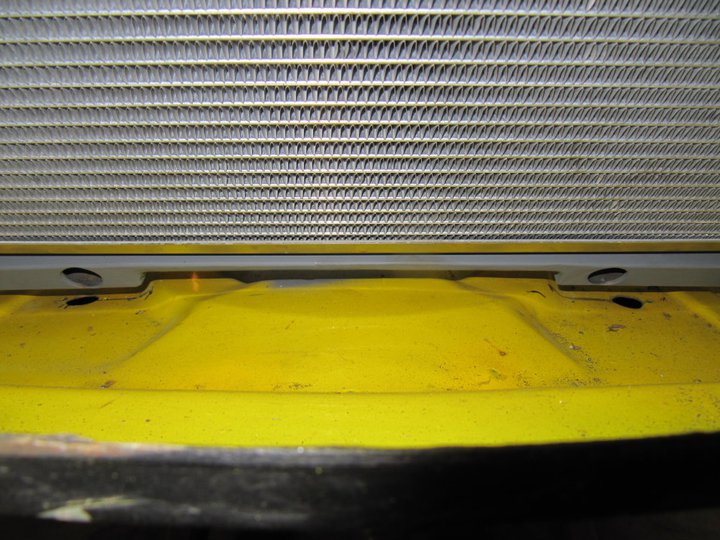
Then I worked on how I was going to fit the fuel tank. Admittedly, the fuel take was small to begin with however this was too big to fit in the small space left in the front trunk. I therefore cut off the back of the fuel tank to follow the contours of the trunk floor.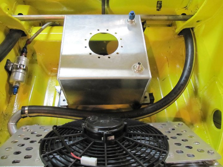
I need to get some more aluminum, but this will be welded up and will work perfectly.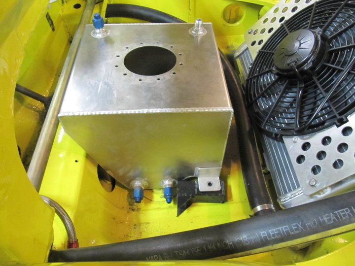
There will eventually be a nice shroud to vent the radiator out the hood. As you can see here, everything should clear nicely. I will make a fuel tank filler neck that will extend back and enable filling the tank without having to take off the shroud.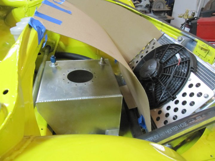
I also was found a nice place to mount the accusump tank. This will be activated by a manual pull release that is just long enough to route to the front.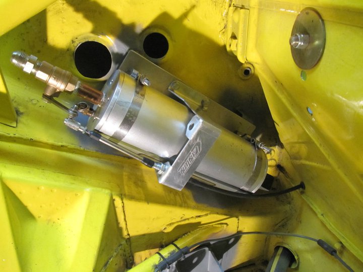
Ok, headed back out there now to continue working.
-Britain
Posted by: Britain Smith Dec 18 2010, 11:10 PM
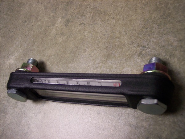
Quick question...for the fuel tank I would like to be able to determine the fuel level without having to put a stick in there. Does anyone know where I can get one of those liquid level sight tubes like the one below...preferably in aluminum and compatible with fuel.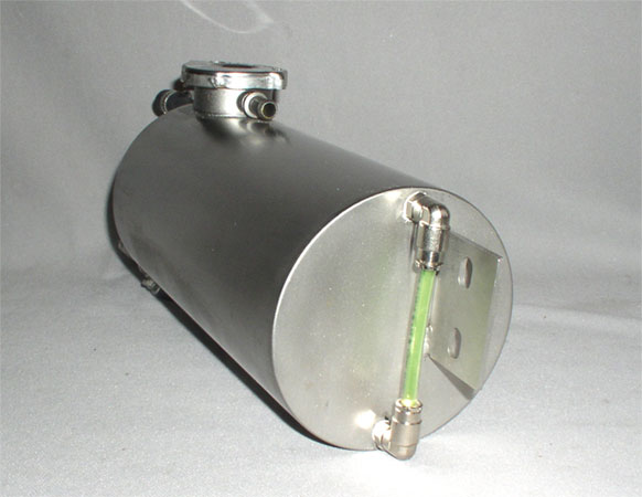
Posted by: McMark Dec 18 2010, 11:59 PM
There's one on http://alumitank.com/fuel_tank_accessories.php that has a thermometer built in as well. 
To fab something like you pictured, just pick up some http://www.mcmaster.com/#compression-tube-fittings/=a7krw6 and http://www.mcmaster.com/#pvc-tubing/=a7ks38 from McMaster-Carr.
Posted by: 396 Dec 19 2010, 08:40 AM
Keep them coming , VERY COOL PROJECT!
Posted by: jd74914 Dec 19 2010, 09:13 AM
Don't use PVC tube. It will melt! (Edited to correct)
The sight gauge you are showing looks like it uses Legris push-to-connect fittings and probably a clear nylon tube. We use them for fluid systems at work because they are low cost and pretty reliable (leak-free) fittings.
Search http://www.mcmaster.com/#push-to-connect-tube-fittings/=a7roga in McMaster and pick out the desired fitting. They sell elbows with one NPT end and a push-to-connect end as shown, so you can just have 2 NPT bungs welded into your tank, screw the fittings in, and be done.
Compression fittings will also work, but I don't have a huge amount of faith in McMaster's stock. They might work fine, but when I'm shopping for compression fittings I always go to Swagelok since the prices are comparable and the Swagelok parts are significantly higher quality.
If you want to go compression fitting, the P/N for an aluminum Swagelok elbow with 1/8"NPT on one side and 1/4" compression on the other is A-400-2-2. To switch to stainless change the A with an SS. If decide to go that route their website has a selector which has all of the fittings you could ever want.
BTW: The project looks good!
Posted by: McMark Dec 19 2010, 01:43 PM
Hmmm, I found a ton of different references to using PVC on fuel tank sight tubes.
Posted by: jd74914 Dec 19 2010, 05:19 PM
Wow...I think I read PVC this morning and thought ABS; my mistake. ABS is what you really don't want to use, though PVC is also rather brittle and can weaken in the presence of unleaded gasoline (per Cole Parmer who has a really complete/accurate chemical resistance database). IMHO the best thing to use is a clear nylon.
I edited the above to avoid any future confusion...
Posted by: ottox914 Dec 19 2010, 05:44 PM
Not like you need more projects, but...
Ducting the back of the radiator out the hood is a great idea, don't forget to duct, or seal the front of the radiator to the front of the car. It may not seem like it would make a difference, but air WILL take the path of least resistance, and around the top, bottom, and sides of your radiator will be that path. Block off those sides, bottom, and top from the first pics of your post 68. Not just with some sheets of aluminum, but include foam to make it as airtight as you can. This comes from a friend of mine who works for CAT making cooling systems for the big diesel engines, intercoolers, oil coolers for earth moving equipment. In his world, with limited ground speed, the airflow needs to be generated by fan speed, and surprising enough to me, they face bigger challenges keeping the fan noise down to meet sound regulations than they do the engine noise. So making the most of every puff of air moving toward the radiator is important, and loosing any of that cooling breeze makes the system less efficient, louder, and more expensive.
Posted by: Britain Smith Dec 19 2010, 07:27 PM
Yep, the radiator will be completely ducted front and rear. All that will be completed after the engine runs on the dyno.
-Britain
Posted by: roadster fan Dec 20 2010, 02:41 PM
For the fuel site gauge look at custom motorcycle suppliers these are installed on bikes all the time.
http://www.kandgcycles.com/CC-632915.html
http://compare.ebay.com/like/330506269681?ltyp=AllFixedPriceItemTypes&var=sbar&rvr_id=187856999374&crlp=1_263602_304662&UA=WXF%3F&GUID=7534187d11e0a0bae217f627ffe9a086&itemid=330506269681&ff4=263602_304662
You may be able to put one together for less than these two links, but thought they may help ya.
Jim
Posted by: JRust Dec 20 2010, 03:44 PM
I would consider modifying or adding some kind of rubber spacing on the radiator. It all looks to be hardmounted. If you get flex up front with it hard mounted your radiator won't last to long. It needs to have some mounts that allow for flex. I know that was why renegade went to a floating radiator setup. Still pretty firm in place but does move enough to allow for flex .
Of course most of what you are doing is over my head anyway  . It being the shitbox it is probably reinforced up there so flex isn't an issue. This is as close to helping as I will probably get
Posted by: Britain Smith Dec 20 2010, 09:09 PM
The mounting points have rubber isolators, the radiator is not hard mounted.
-Britain
Posted by: plymouth37 Dec 20 2010, 10:44 PM
Nice work, I was thinking about mounting my turbo in that location for a while, looks great!
Posted by: JRust Dec 21 2010, 12:26 AM
The mounting points have rubber isolators, the radiator is not hard mounted.
-Britain
I figured I should have kept my mouth shut
.You do everything so nice I should have known. I just didn't see them. Conversion is looking great 
Posted by: Britain Smith Dec 21 2010, 02:45 AM
Nice work, I was thinking about mounting my turbo in that location for a while, looks great!
Thanks. I went through your thread many times before starting my conversion. Like you, I like to do things a little different
-Britain
Posted by: Britain Smith Dec 21 2010, 02:46 AM
The mounting points have rubber isolators, the radiator is not hard mounted.
-Britain
I figured I should have kept my mouth shut
.You do everything so nice I should have known. I just didn't see them. Conversion is looking great No worries Jamie...feel free the chime in anytime.
-Britain
Posted by: Britain Smith Dec 21 2010, 03:18 AM
I had the day off work and was able to get a couple of things done.
First off, I had the backside of the fuel tank welded up and some tabs mounted. 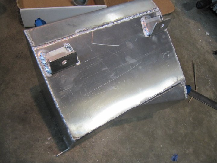
With a set of brackets made, the fuel tank now fits perfectly in the available trunk space.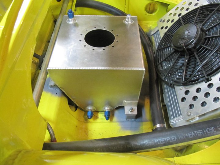
I also got the engine back to my garage after having all the exhaust all tig welded up. I added a flex joint in-between the two wastegates to aid in installation. 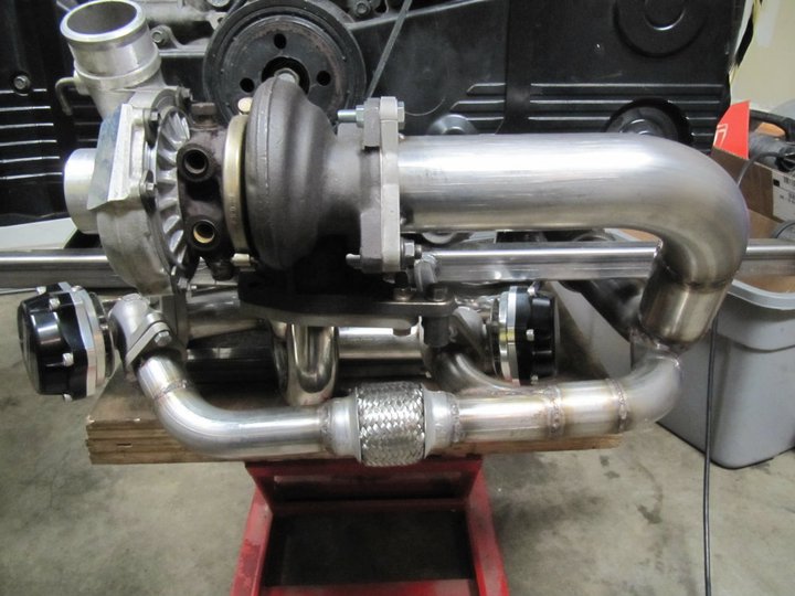
Overview shot of the engine...almost ready to go, just a few more things to do.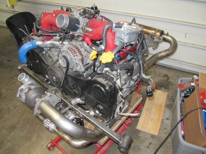
Some of you might know, but I have a special 2-speed transmission in this car. In addition, the placement of the header and turbo make it virtually impossible to pass a shift bar through to the transmission. Therefore I have converted to a cable shift set-up. Here is my new shifter I built today. 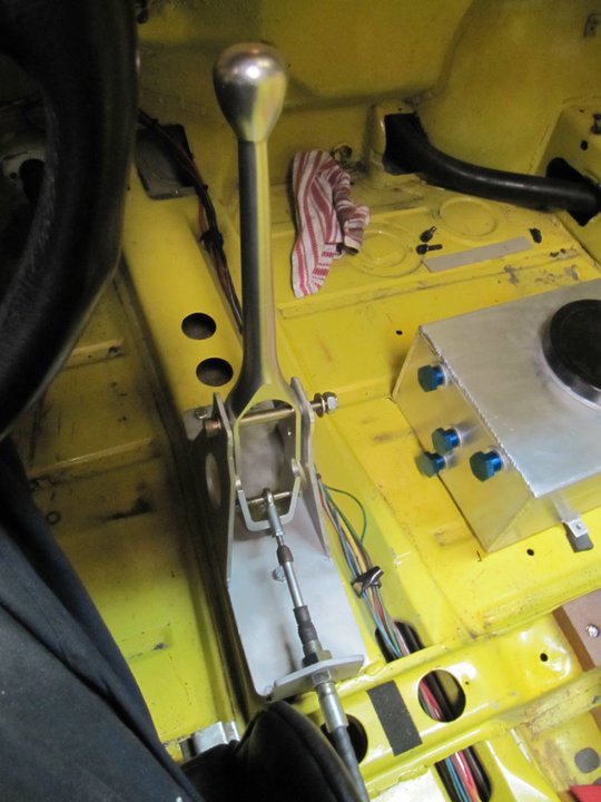
I will need to have a pair of small spacers made tomorrow at the machine shop to correctly position the hem joint, but the functionality works. Here is a short video of the motion.
http://www.youtube.com/watch?v=jDVTPXrR66o
Finally, I started working on the placement of the pedal assembly. Does anyone have any experience with mounted a set of these on the uneven floorpan. I haven't decided if I want to mount them to the aluminum or just cut out the raised portions of the floorpan and weld in a flat panel.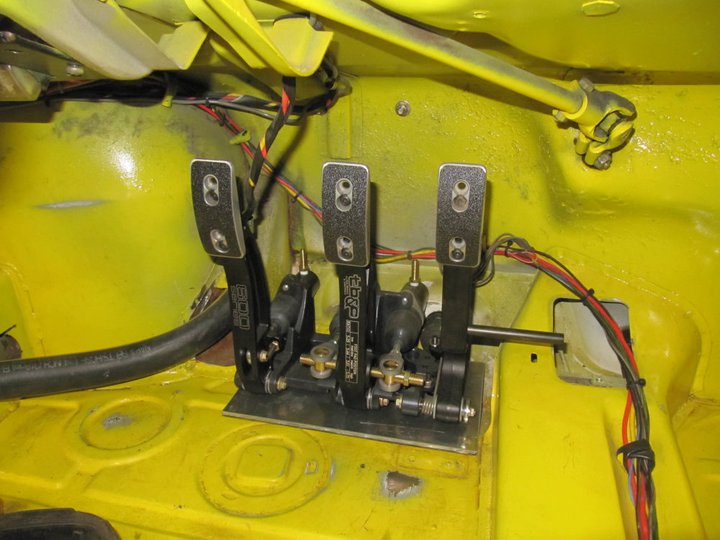
More to come...
Posted by: sixnotfour Dec 21 2010, 07:48 AM
I hope your are planning a Ken Block-ish kinda debut - filmed @ packwood maybe ? 
Posted by: Britain Smith Dec 21 2010, 11:17 AM
Ha...that would be fun!
Posted by: J P Stein Jan 1 2011, 03:17 PM
Bump.....Brit is now back in the USofA, but he'll prolly be talkin' Texan for a few months & will have to relearn typing.
Posted by: Randal Jan 3 2011, 10:14 AM
Sure like the way the SB is being put together Britain. Every step / challenge you've encountered has been solved (very) smoothly.
Can't wait to see that baby run.
Whole new experience I'm thinking.
Posted by: Britain Smith Jan 3 2011, 01:22 PM
Being out of town for a week got me out of the groove for a couple of days, but I started back in it last night.
The first thing that I tackled was the routing of the coolant lines for the turbo. The stock routing simply would not clear the firewall, here is how it originally looked.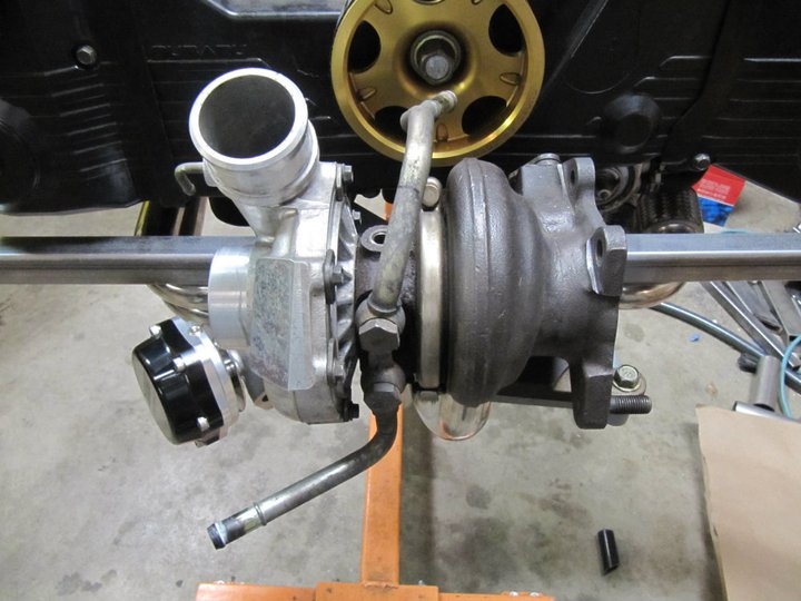
After a little cutting and welding, they are now routed properly.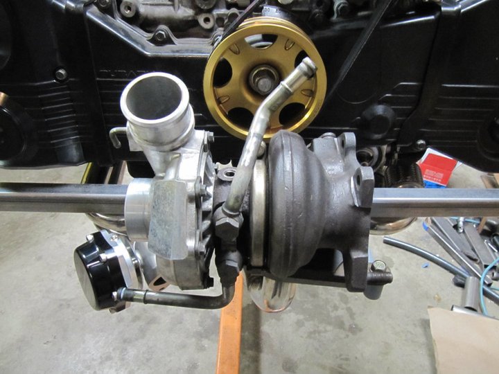
And here they are with the coolant hoses attached. The feed line comes from the reservoir tank and the return goes to the stock location at the back of the head.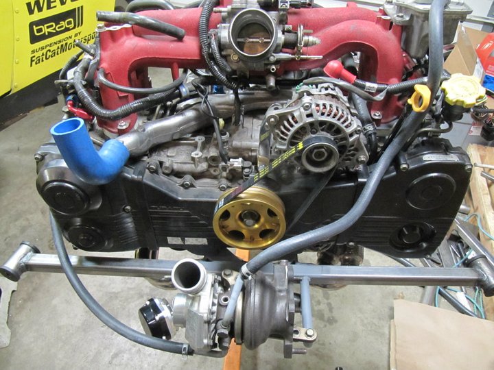
In a previous image, you may have noticed that rubber coolant line ran very close to the exhaust downpipe...a little too close for comfort. I therefore constructed an aluminum coolant line that routes farther from the exhaust.
Here is the original rubber coolant line in place.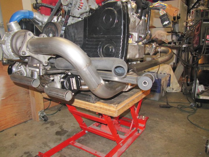
And here is the aluminum coolant line.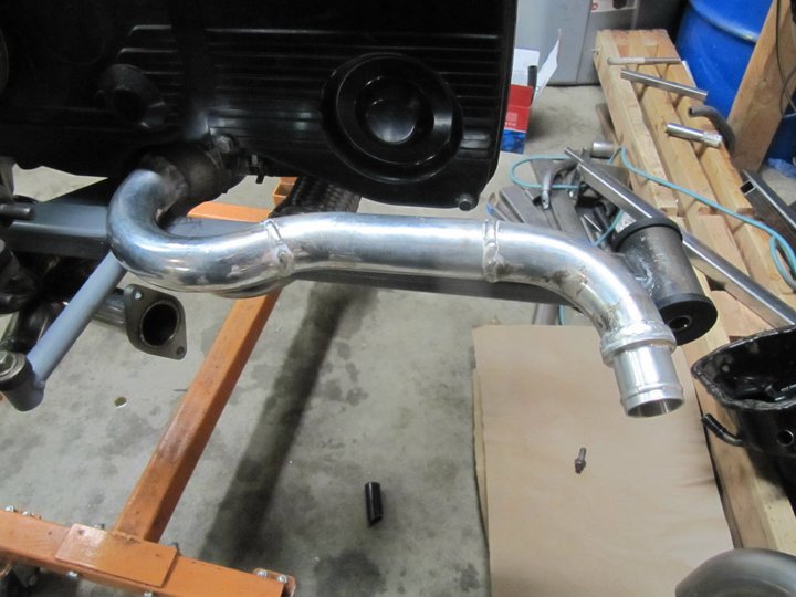
Another item that I had some comment on was regarding the structural integrity of the square tubing engine mount bar. I had plans to reinforce this from the beginning, but I needed to finish the mounting of a few other items before constructing this plate. It is 3/16" mild steel cut out on a waterjet and stitch welded across the entire length.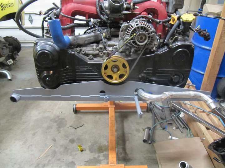
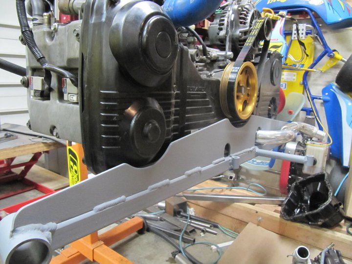
The aluminum coolant pipe will be supported with a bracket hanging off this plate.
The last thing I started work on was the mounting of the pedal assembly. I explored the option of bolting it to an aluminum plate then securing that plate to the floorboard, but the entire thing was going to raise the pedal assembly an additional 1/2" off the floor. I have now decided that I am going to weld in a steel plate in-between the floor ribs to reinforce the floor pan and provide a flat surface to bolt the pedal assembly in.
Here is the floor pan in the pedal cluster area, you can see the multiple ribs and recesses. (Ignore the brake master assembly in there, I haven't lifted the car off the lift to pull this out yet)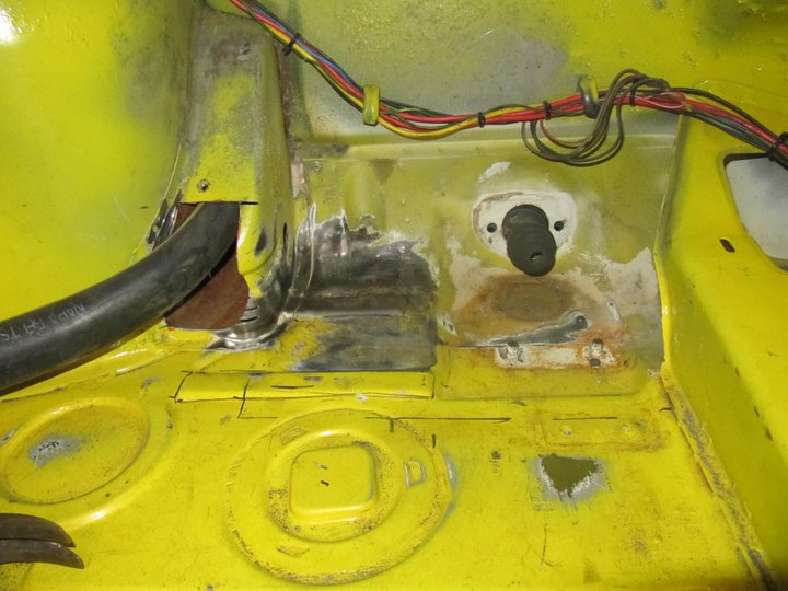
Here is the steel plate that cut out to fit, there will be some vertical plates welded to the bottom of this to account for the variation in floor thickness.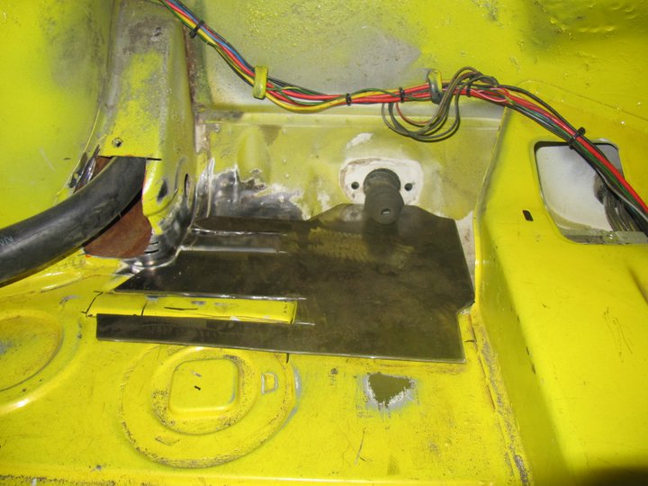
And here is Tilton pedal assembly in its final resting place. The new pedals will take some getting used to, but at first pass I like them.
More to come soon,
Britain
Posted by: Britain Smith Jan 3 2011, 01:42 PM
Sure like the way your putting that car together Britain. Every step / challenge you've encountered has been solved (very) smoothly.
Can't wait to see that baby run.
Whole new experience I'm thinking.
Thanks Randal...hope to see you again...maybe at the WCR in Medford.
-Britain
Posted by: Derek Seymour Jan 3 2011, 02:14 PM
Sure like the way your putting that car together Britain. Every step / challenge you've encountered has been solved (very) smoothly.
Can't wait to see that baby run.
Whole new experience I'm thinking.
Thanks Randal...hope to see you again...maybe at the WCR in Medford.
-Britain
This may have been addressed, but I was curious if you planned on fabricating a dead pedal/heat shield.
During hard cornering I have always liked the advantage of a dead pedal, but with the radiator line you have there as well I can visualize a bit more complicated yet effective design alternative to the standard dead pedal.
Posted by: Rod Jan 3 2011, 02:17 PM
Hat doffed Britain, amazing work
I'm thinking about going the scooby route too over a six and I think the last 25 minutes reading through your thread has convinced me it's the way to go
Keep up the exceptional work!
Posted by: ChrisNPDrider Jan 3 2011, 03:34 PM
When is the date with the dyno?
I bet you have already done this, and are just tuning for the best pull on round 2.
???
Posted by: Britain Smith Jan 3 2011, 05:38 PM
This may have been addressed, but I was curious if you planned on fabricating a dead pedal/heat shield.
During hard cornering I have always liked the advantage of a dead pedal, but with the radiator line you have there as well I can visualize a bit more complicated yet effective design alternative to the standard dead pedal.
Yep, there will be a fabricated shield over the coolant lines on both sides of the car. The drive side shield will incorporate a dead pedal.
-Britain
Posted by: Britain Smith Jan 3 2011, 05:40 PM
When is the date with the dyno?
I bet you have already done this, and are just tuning for the best pull on round 2.
???
Well, the goal is to have the car running (not yet on the dyno) by the end of January. However, the custom flywheel that is being made won't be ready for another 3 weeks so we shall see.
-Britain
Posted by: PeeGreen 914 Jan 3 2011, 05:46 PM
Can't wait to see this run Britain I'm seeing a good AX year for you 
Posted by: J P Stein Jan 3 2011, 06:17 PM
I am really curious to see how much the car weighs when "done"(less ballast & driver) but with a couple gallons of gas
We prolly ought have to have a contest. I'll throw in a $hitbox tee shirt to the winner. Only slightly used, worn only in parking lots.
Starting weight is 1715 with gas. Time/date entries if you're interested.
Posted by: Rand Jan 3 2011, 06:21 PM
#1675
Posted by: Britain Smith Jan 3 2011, 06:21 PM
Ha, fun contest. I believe that I have an brand new $hitbox shirt somewhere.
-Britain
Posted by: J P Stein Jan 3 2011, 06:25 PM
Heh.....I have a new one in my T drawer.....the other has real live Packwood gravel embedded in it....a collectors item.
Posted by: Britain Smith Jan 8 2011, 04:53 PM
Progress has been a bit slow the last couple of days, but it is starting to pick back up.
Finished up the front truck area. I replaced the foam in the fuel tank and completed all the fuel lines.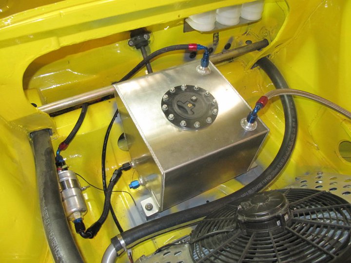
Got the AIM MXL dash mounted and ordered the Subaru interface harness so that I can read everything off the ECU. 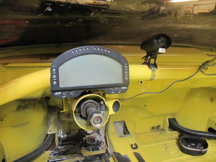
I also started plumbing all the brake lines and drew up the wiring diagram.
-Britain
Posted by: Hontec Jan 9 2011, 04:12 AM
Read the whole topic ......again...... Simply amazing work Britain..
Love the Tilton pedal box.......I will be installing a similar one......
Keep up the great work, you're certainly doing a lot in a short period of time....
Posted by: Britain Smith Jan 9 2011, 05:06 AM
Thanks Hontec...your work is far superior, I am just trying to get my car together before the race season starts.
I got the welder back from my buddy who I am borrow it from so I was able to make good progress tonight. First I finished up clean the firewall. There were several large holes that were used to secure the 914/6 engine mount that have now been welded up.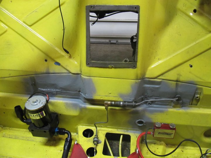
View from the backside of the firewall with the holes welded up and the brake line rerouted to avoid hitting the turbo.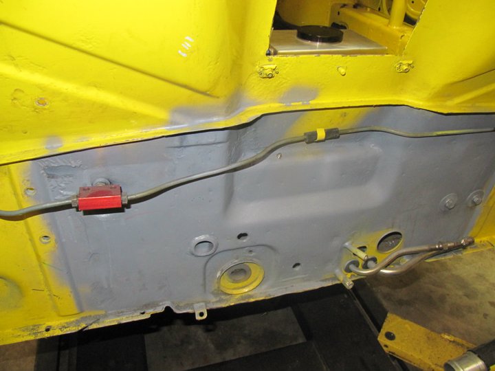
Turbosmart Dual Stage Boost Controller taken off my '69 912 Turbo project. This will work well for those tighter courses or wet weather occasions.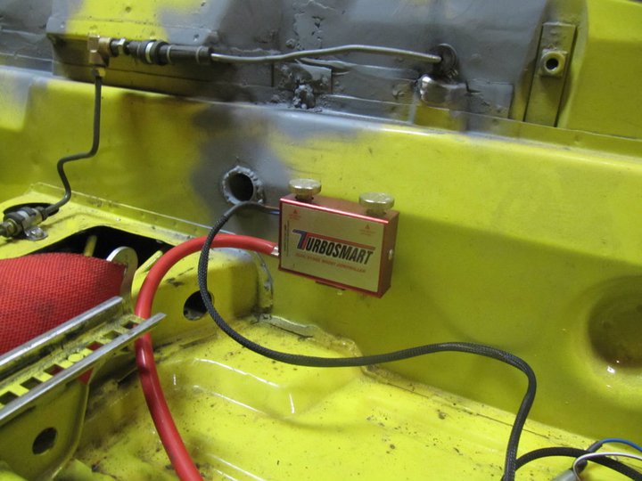
Pedal assembly plate welded in. These welds are not as pretty as I would have liked, however trying to weld in the cramped footwell was not easy and I had to ensure I didn't burn thru the floorpan.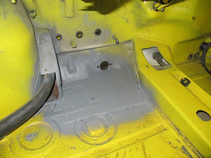
Tilton pedal assembly mounted. The positioning is perfect and the mount is very sturdy.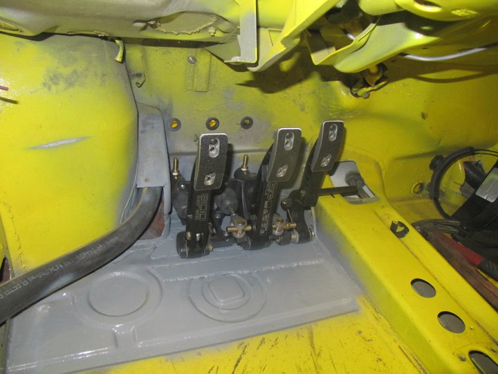
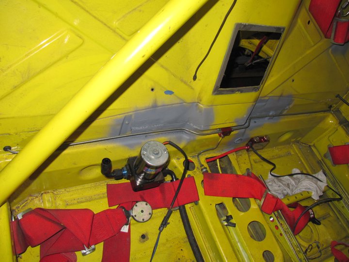
Intercooler ice box mounted. This will fit just in front of the passenger seat when I take passengers.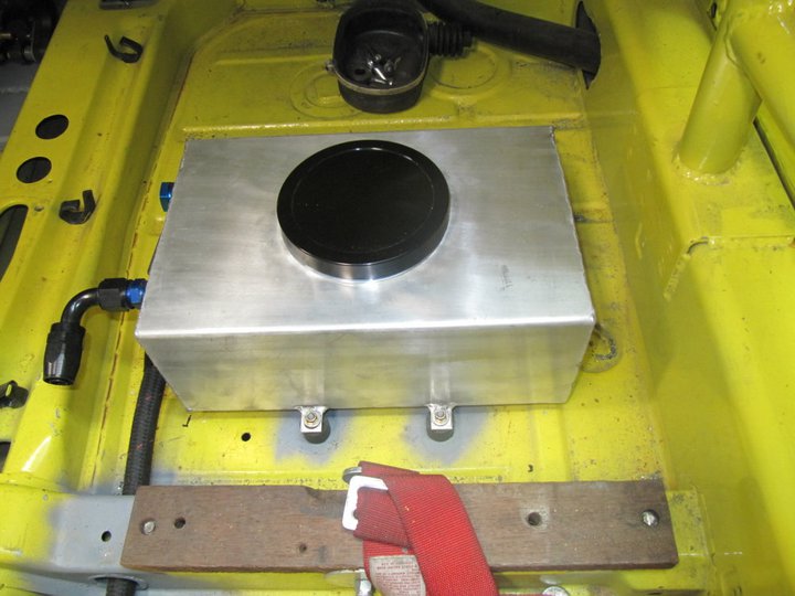
Ice box plumbing. There is a ball-valve to drain the water under the car.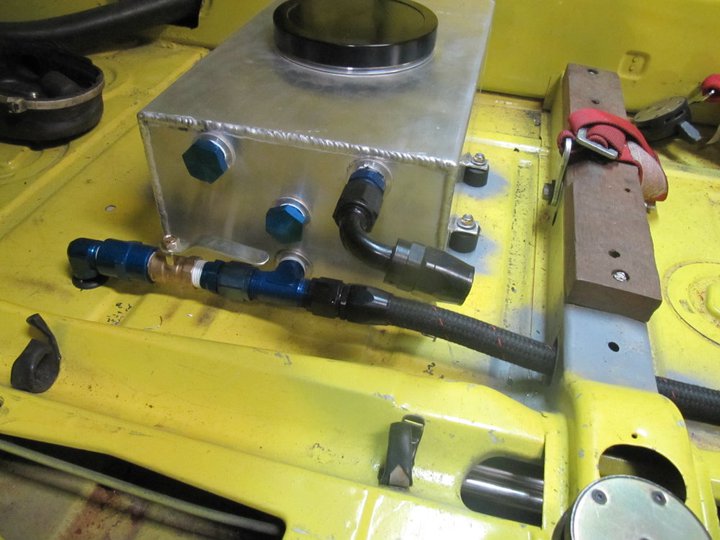
Ice box plumbing view down to the water pump. Had to route the lower water hose thru the crossbar so I welded in a tube to keep the strenght.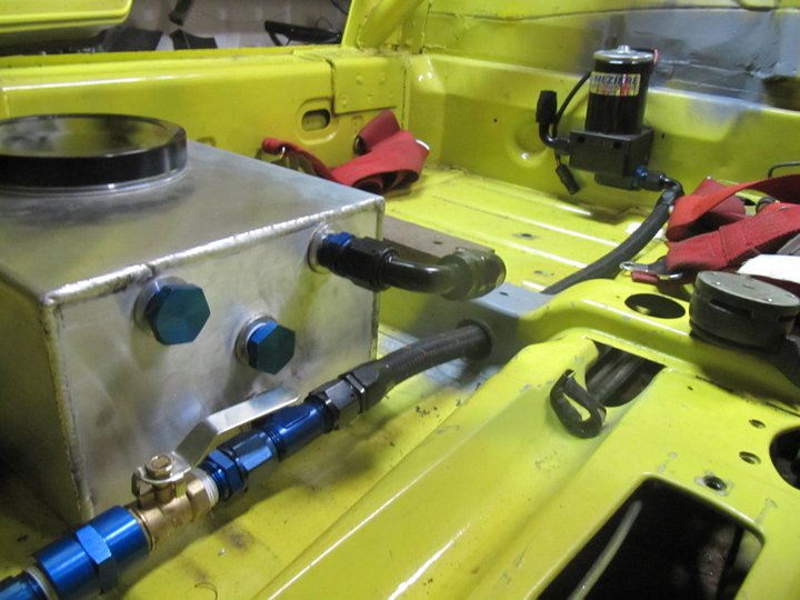
Off to bed, more to do tomorrow.
-Britain
Posted by: plymouth37 Jan 9 2011, 05:07 AM
Beautiful as usual, this is going to be one hell of a ride!
Posted by: Britain Smith Jan 9 2011, 05:09 AM
Ha, you are up just as late as I am...best time to get things done.
-Britain
Posted by: Hontec Jan 9 2011, 06:04 AM
Lookin' good!!! really love the pedalbox! and the dash is 
Posted by: Britain Smith Jan 17 2011, 01:47 AM
Took the son karting yesterday. It was his first time at a dirt flat track and although he started off slow, he really got the hang of it and it was a lot of fun. 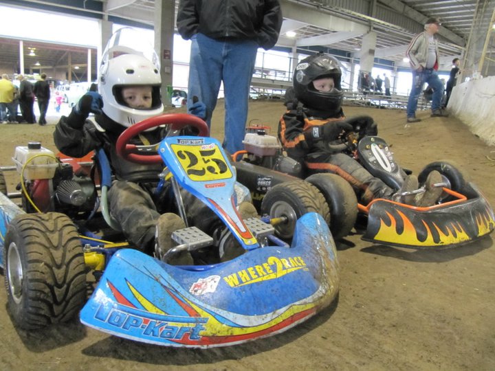
Anyway, back to work. Got the business end almost completed. Just had to put the seat back in to feel the new pedal/shifter/dash set-up. I will admit, I did sit there and make car noises for a bit. The last thing that needs to get done here is a panel for the ignition switches.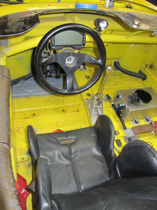
Reinstalled the engine to take some measurements for the throttle cable and clutch hose. Got the air intake installed and a bracket made to mount it. 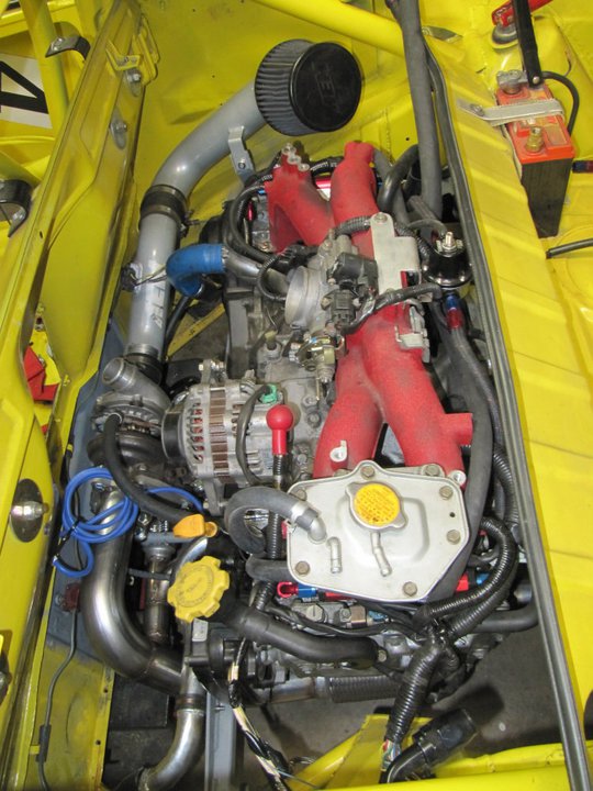
Fuel lines installed. Startlite line may cost a little bit more, but it is SO much nicer to work with and lighter.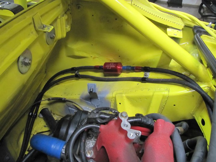
Got the intercooler back from being welded up by Marty Staggs (www.m-specmotorsports.com), turned out perfect.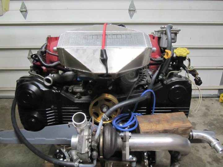
Starting to fab up a heavy duty mount off the engine block. The intercooler is fairly heavy as it sits and will be twice as heavy when the water is added.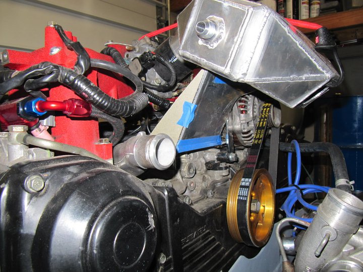
Hopefully I can wrap up all the fab items over the next week or so and then focus on the wiring. Although I am still waiting on my custom flywheel, I am still on track to have this thing fired up by the beginning of Feb.
-Britain
Posted by: Britain Smith Jan 19 2011, 01:17 AM
Was able to take the intercooler mount to the machine shop today and get welded up so that I could finish the routing of the intake piping. I also had some aluminum standoffs machined up to mount the bracket to the top of the engine block where the original alternator and power steering brackets were secured. I will take the rest of this to get welded up later this week.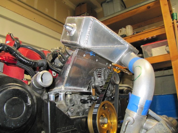
Intake piping between the turbo and intercooler mocked up.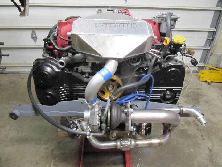
Even though I rotated the compressor side of the turbo I was still able to use a Grimmspeed bracket (with a little modification) to lock the internal wastegate closed.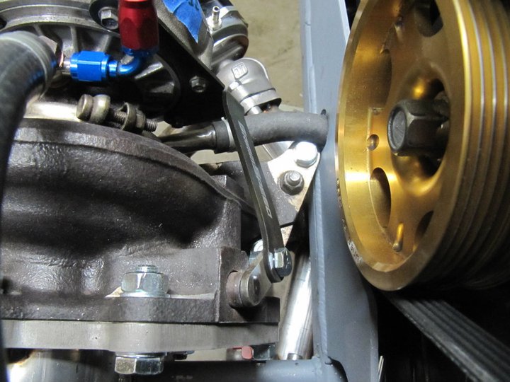
Found a nice solution for the oil feed to the turbo from Forced Performance. Consists of a custom made banjo bolt machined with an AN-4 male fitting on the end. The stock hard line that used to feed the turbo has a machined fitting to cap the oddball size threads. I will run a short lenght of AN-4 hose over to the turbo.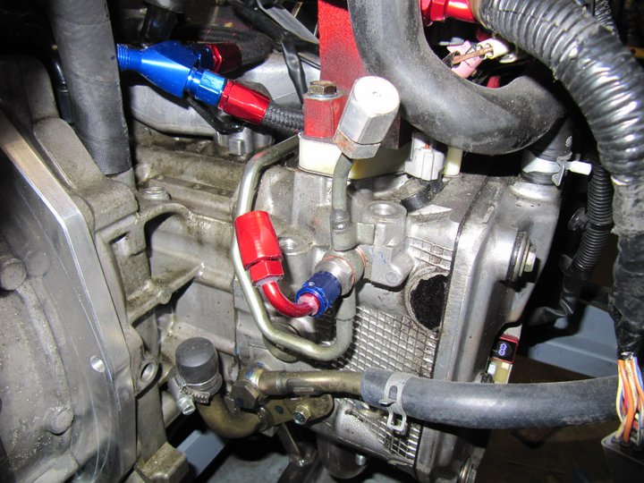
While I was having other aluminum stuff welded today, I took the time to add some reinforcements plates to the shifter housing after I found that it was flexing just a little bit where the cable mounts.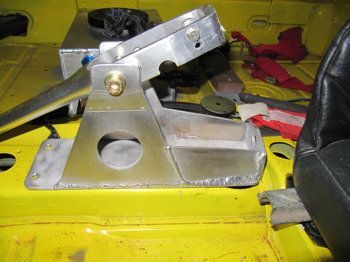
-Britain
Posted by: URY914 Jan 19 2011, 08:48 AM
I like it.
Posted by: sean_v8_914 Jan 19 2011, 09:05 AM
bravo zulu!
Posted by: sawtooth Jan 19 2011, 11:10 AM
Fantastic! Nearing the end of my suby conversion, I am baffled by the mount of knowledge and confidence it would take make something like this come together, especially how fast you are getting it done. I'm jealous of your knowledge of turbos, what to use and why, and how to make it all come together. Keep up the great work, hope to see your car run ax at WCR!
Posted by: Britain Smith Jan 19 2011, 01:15 PM
I learned a lot when I did my 912 Turbo project. I have also done a lot of research and planning...that and I like to do things a little different.
-Britain
Posted by: Elliot Cannon Jan 19 2011, 01:21 PM
Will we see this monster at the WCR?
Posted by: Britain Smith Jan 19 2011, 01:58 PM
That is the plan...
-Britain
Posted by: Walter Jan 19 2011, 03:43 PM
Very nice work indeed!
If you're aiming at ~400 hp, I would have chosen a 3" downpipe however, especially since you've also routed the wastegates in the 2,5" piping.
Well, you can always 'upgrade' later if you would want to ;-)
Posted by: Britain Smith Jan 19 2011, 03:49 PM
The wastegate piping goes from 1.5" to 1.75" then into the exhaust which is 2.5"
-Britain
Posted by: Walter Jan 19 2011, 04:01 PM
The wastegate piping goes from 1.5" to 1.75" then into the exhaust which is 2.5"
-Britain
I know, I had read that
Its just a little better then internal wastegate(s) what you did as the whole idea to external besides the control side is to not 'mess up' the exhaust flow giving it extra back pressure, even if its a few psi.
Turbo's are very sensite to back pressure and 2.5"is on the small-ish side for 400 hp. Better is to route ext. gates into their own downpipes and their own silencers.
Another thing to consider if you get dB problems with some tracks is the ext.gates actually need even better silencers as they don't have the turbo to pre-silence them... I also found this out the hard way at soem track when my wastegate opened and I got past the post that measured sound...
Just thinking along with you Britain ;-)
Posted by: Britain Smith Jan 19 2011, 04:10 PM
Understood Walter.
Since the engine is only a 2.0L and I am running the stock turbo (for faster spool time) I don't plan on getting 400hp...more like 350hp max. The path towards external wastegates was for better control of boost pressure as the internal gate has issues when running over 20lbs of boost as I plan to run. It also helps that I am partially sponsored by Turbosmart and have their wastegates, BOV, and fuel pressure regulator on my car.
Regarding the exhaust routing, the need to combine them into the exhaust stream was necessary due to not only sounds requirements but also restricted space. By dumping into the exhaust stream, I am able to control the sound levels thru muffler arrangements. Now, you are correct it would have been better to dump into their own silencers, however space is limited and that also weighs more
-Britain
Posted by: plymouth37 Jan 19 2011, 10:46 PM
Wow! Looks amazing!
Posted by: Elliot Cannon Jan 19 2011, 11:19 PM
That is the plan...
-Britain
Will we all get to drive it?


Posted by: Britain Smith Jan 20 2011, 01:36 AM
You all get to watch me drive it, that should be satisfaction enough right?
-Britain
Posted by: maf914 Jan 20 2011, 09:01 AM
Britain, Beatiful work! Thanks for posting this thread.
Okay, I suspect this will be a dumb question. Regarding your shifter arrangement, I can see the fore and aft motion, but how does that single cable provide a twisting or side to side motion? A two speed, one-two shift? Or is it a sequential shift?
Posted by: Rand Jan 20 2011, 12:01 PM
Okay, I suspect this will be a dumb question. Regarding your shifter arrangement, I can see the fore and aft motion, but how does that single cable provide a twisting or side to side motion? A two speed, one-two shift? Or is it a sequential shift?
See post #84
Posted by: maf914 Jan 20 2011, 12:17 PM
Okay, I suspect this will be a dumb question. Regarding your shifter arrangement, I can see the fore and aft motion, but how does that single cable provide a twisting or side to side motion? A two speed, one-two shift? Or is it a sequential shift?
See post #84
I quess I was right. It was a dumb question.

Thanks for clearing that up, Rand.
Posted by: Britain Smith Jan 20 2011, 12:20 PM
Yep...special 2-speed transmission.
Thanks for the good words.
-Britain
Posted by: ChrisNPDrider Jan 20 2011, 02:50 PM
Awesome.
I had a big heavy battery break its mount in an AX race, so totally appreciate the extra thought and work you did to mount the intercooler. Water is so heavy, maybe why Porsche stayed away from it so long....
One day I hope to steal one of your ideas = the cooler mounted in front of the passenger seat. Genius! Although mine would have room for beverages 
Posted by: Britain Smith Jan 23 2011, 06:20 PM
I was on a roll last night and up pretty late, but made some good progress.
Intercooler mounting completed. Everything fit pretty well considering I had to mock it up at home and take it to a shop to get welded.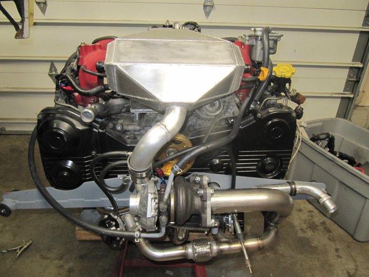
Turbosmart BOV mounted on the underside of the intercooler just before the throttle body.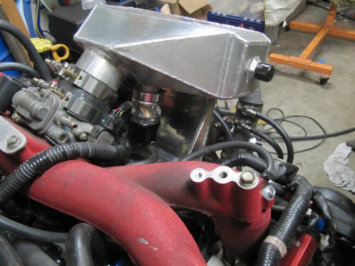
New gauge panel completed and mounted. I had this piece waterjet so that all the holes with line up properly and saved me a bit of time.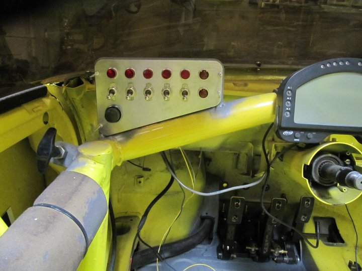
Front fuse box and relays for fuel pump, radiator fan, and intercooler water pump.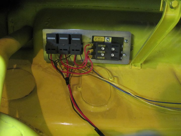
ECU mounted in the trunk. Not looking forward to sorting out the wiring.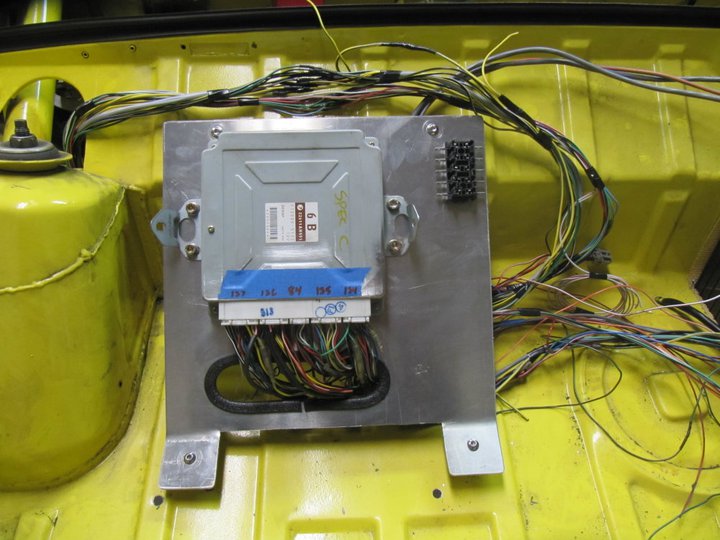
I should be able to get the engine back in there this evening and start finalizing all the plumbing.
-Britain
Posted by: bam914 Jan 23 2011, 08:51 PM
Are the floor mount pedals installed any further forward then the stock setup? Thinking about them for my car.
Posted by: BMXerror Jan 23 2011, 09:52 PM
All your stuff looks so damn good... Professional, even. Must be the yellow background it all goes in front of. 
Makes me jealous. Keep up the good work. Can't wait to see what it does in XP.
Mark D.
Posted by: Britain Smith Jan 23 2011, 11:53 PM
Are the floor mount pedals installed any further forward then the stock setup? Thinking about them for my car.
With the very short master cylinders from Howe Racing they are set identical to the stock set-up. Sitting in the seat they feel perfect. Under that steel plate I made some ribs to ensure I have no flexing of the mount.
-Britain
Posted by: Britain Smith Jan 23 2011, 11:54 PM
All your stuff looks so damn good... Professional, even. Must be the yellow background it all goes in front of.
Makes me jealous.
Keep up the good work. Can't wait to see what it does in XP.Mark D.
Many Many Hours my friend. I have almost 3 straight months on this and I don't want to even mention the budget other than to say that I am "slightly" over
-Britain
Posted by: Britain Smith Jan 24 2011, 12:14 AM
Got up late this morning after the late night last night...but once I got going I got some good stuff done.
Third iteration of the brake line routing. The 2nd iteration interfered with the brake line routing. This time the brake lines are routed inside the cabin and then thru the firewall over the framerails.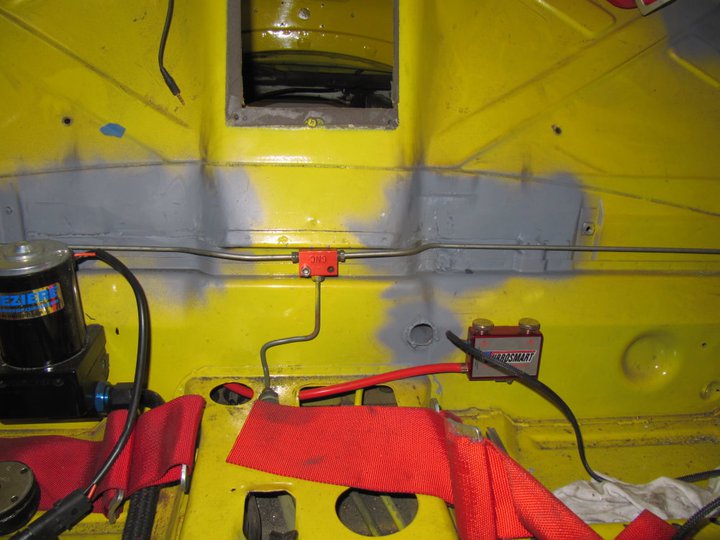
Engine bay with the intercooler installed. Getting pretty busy in there.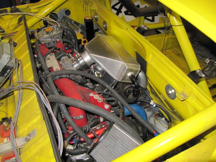
Intercooler water lines routed thru the firewall to the pump/tank.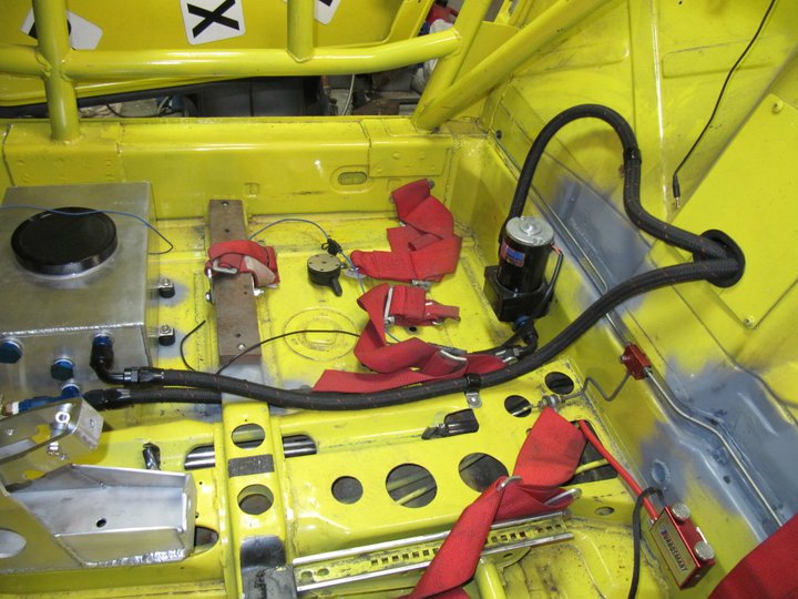
-Britain
Posted by: bam914 Jan 24 2011, 05:58 AM
I found these last night. You build a box over the master cylinders for your feet. I am 6'4" this would be nice to get the pedals further forward.
Posted by: Britain Smith Jan 24 2011, 10:42 AM
Wow, those look cool. Where did you find them? Little late for my car, but nice to keep as a reference.
-Britain
Posted by: John Jentz Jan 24 2011, 05:19 PM
I found these last night. You build a box over the master cylinders for your feet. I am 6'4" this would be nice to get the pedals further forward.
Blake,
Turn them over and hang them from the top bulkhead.
Posted by: BKLA Jan 24 2011, 06:59 PM
This thread sucks! And your mother dresses you funny!
See you Saturday with s'more karting stuff!
Posted by: bam914 Jan 24 2011, 07:44 PM
I found these last night. You build a box over the master cylinders for your feet. I am 6'4" this would be nice to get the pedals further forward.
Blake,
Turn them over and hang them from the top bulkhead.
These require no cutting or major bracket making. I don't like hanging pedals.
Here is the company that has them. http://obpltd.com/
Posted by: BMXerror Jan 24 2011, 10:00 PM
Many Many Hours my friend. I have almost 3 straight months on this and I don't want to even mention the budget other than to say that I am "slightly" over
-Britain
I hear that. I've had some days lately where I work a ten hour shift at the machine shop, and then stay an extra 8 hrs making some part for the SDS install. Hard work: You never get anywhere without it. Keep on keepin' on Britt.
Mark D.
Posted by: Britain Smith Feb 3 2011, 01:44 AM
Summary of the work completed over the last couple of days.
Went to install the starter and finish up the wiring and found that the position of the engine caused the starter to hit the trunk floor. Therefore I had to make this raised panel for clearance.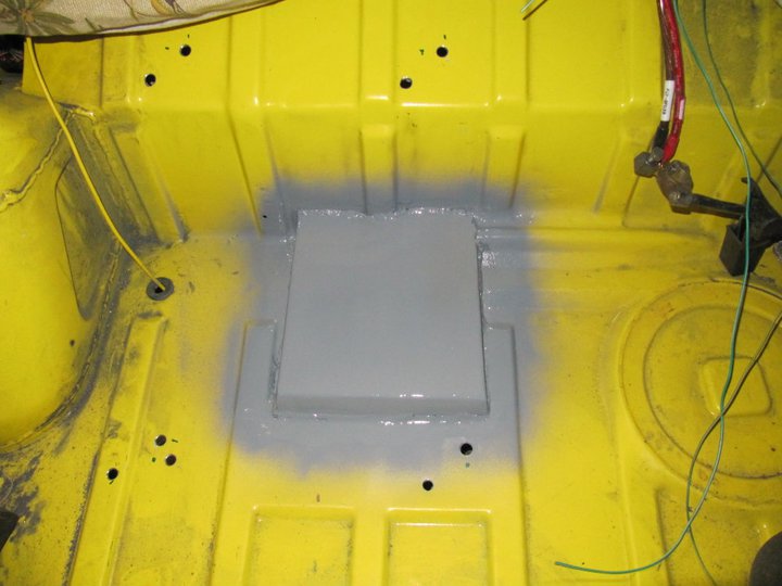
View from underneath. I made the panel with the transmission in the car. When I pull the trans to install the new flywheel I will clean this area up.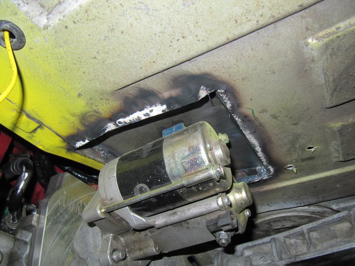
Throttle cable bracket completed and all adjusted. The feel of the throttle pedal is perfect.
(I got the throttle cable made custom from Terrycable and due to an error on my part, the first one I ordered was a bit short. If anyone is building a Suby conversion and needs a throttle cable 90" long let me know. It would work perfectly on a car with the intake manifold in the stock orientation (i.e. pointing back).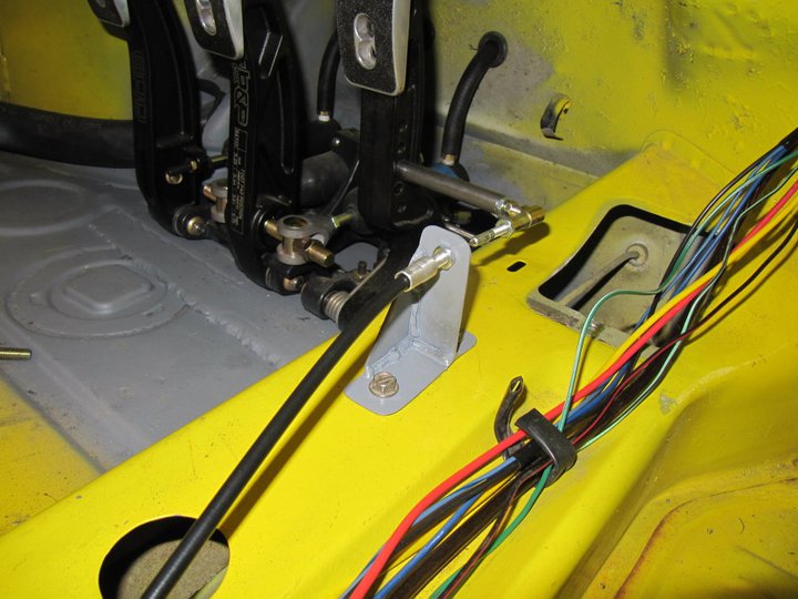
Throttle cable mounted in the engine compartment.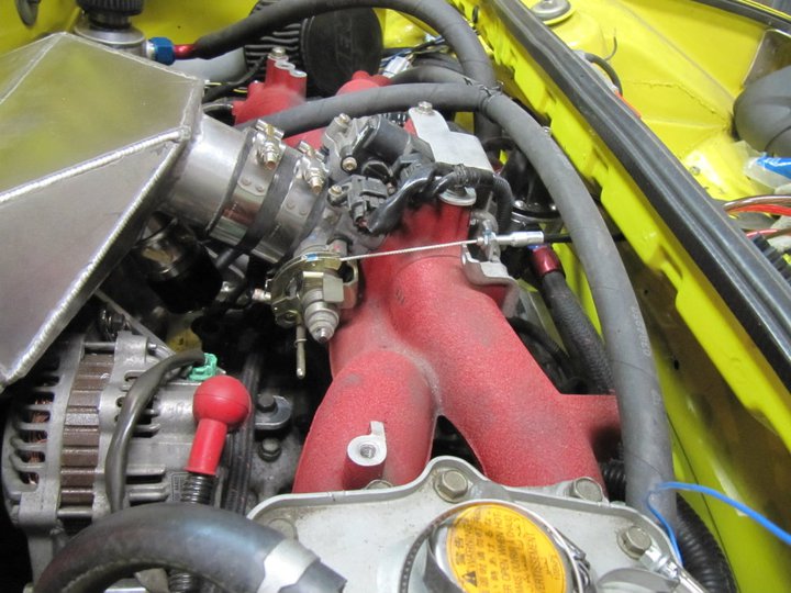
ECU mounting and the majority of the wiring completed. Still need to finish the alternator wiring and some various sensor for the VSS (Vesicle Speed Sensor) and NPS (Neutral Position Switch).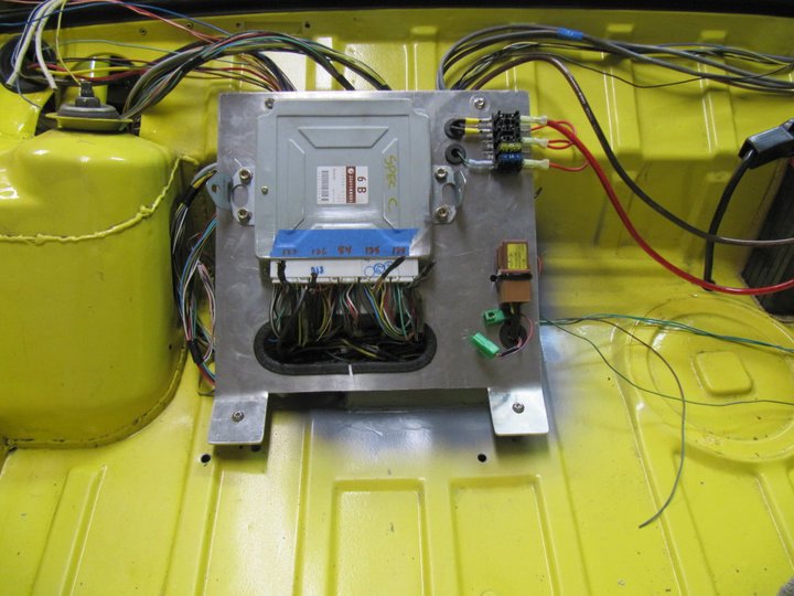
Switch panel has power. Lets see, we got master on, fuel pump, radiator fan, intercooler water pump, and boost switch.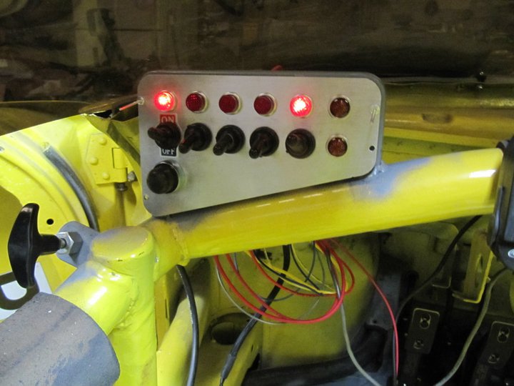
Dash display wired in and working. Not sure where it is getting the Oil/Water/EGT numbers as the ECU was not on...maybe memory from the engine it was installed on previously.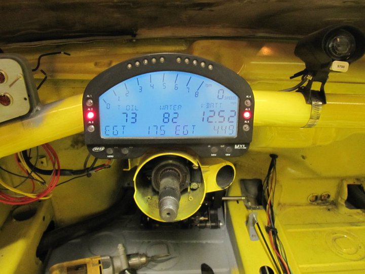
Right now the ETA on the custom flywheel is end of next week. If that happens then I should make it to the dyno the week of Feb 14th...almost there
-Britain
Posted by: Rod Feb 3 2011, 09:30 AM
Superb - Really gaining pace now. If it were me I'd want to strip it all out and respray the shell inside and out - it just looks soo good
Posted by: Britain Smith Feb 3 2011, 11:34 AM
Superb - Really gaining pace now. If it were me I'd want to strip it all out and respray the shell inside and out - it just looks soo good
Yea, that would be a great plan if I had 6 more months to build the car...however, the race season started in 4 weeks. I need as much time as I can get to finish the car and start sorting it out.
-Britain
Posted by: ChrisNPDrider Feb 3 2011, 03:30 PM
I am loving the blend of old and new in your 914
Inspirational work. Subby transplants are just so nice. I am sure it will be smokin fast with less fuel consumption
Posted by: grantsfo Feb 6 2011, 09:32 PM
Looking good Brit! I knew you would eventually figure out how to make a fast prepared ax 914! I'm about to throw up my hands like JP did and dump the Boxster to someone who has time and money to do it right. Most people have no idea what it takes to build a national level ax car. If you think about it this 914 has been in serious development in modified and prepared form for over 7 years and I think it's just getting to the point of being nationally competitive in prepared this season but suspect you have lots of sorting left prior to nationals. I suspect you will be working on suspension balance as turbo power is sure to be different than NA car was setup. Again this is very exciting!
Looking forward to seeing it run with big dogs! Are you coming down to SD again?
Posted by: Britain Smith Feb 6 2011, 09:50 PM
Hey Grant...haven't heard from you in a while.
I have a dyno date in 2 weeks so I am in the final push to get this thing running. I doubt I will make San Diego this year as it is a little too close to ensure I have the car sorted. We shall see what happens over the next few weeks.
-Britain
Posted by: Britain Smith Feb 7 2011, 11:01 AM
Ok, I am on the final push towards the end. I have dyno time schedules for Friday, Feb 18th at Cobb Tuning Surgeline. Still waiting on the flywheel, but I can get everything else prepared in advance.
Reprogrammed the dash for a little pre-race inspiration. I also wired up the oil pressure, oil temp, fuel pressure, and water temp sensors to monitor on the dash.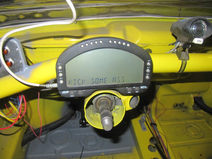
For radiator venting thru the hood, I purchased two louvered panels. These things were pricey and I was less than impressed with the quality. However, they will serve a purpose and I have to remind myself that this is just a race car.
Here are the panels in the approximate location on the hood.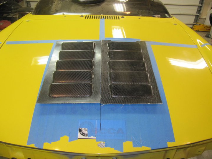
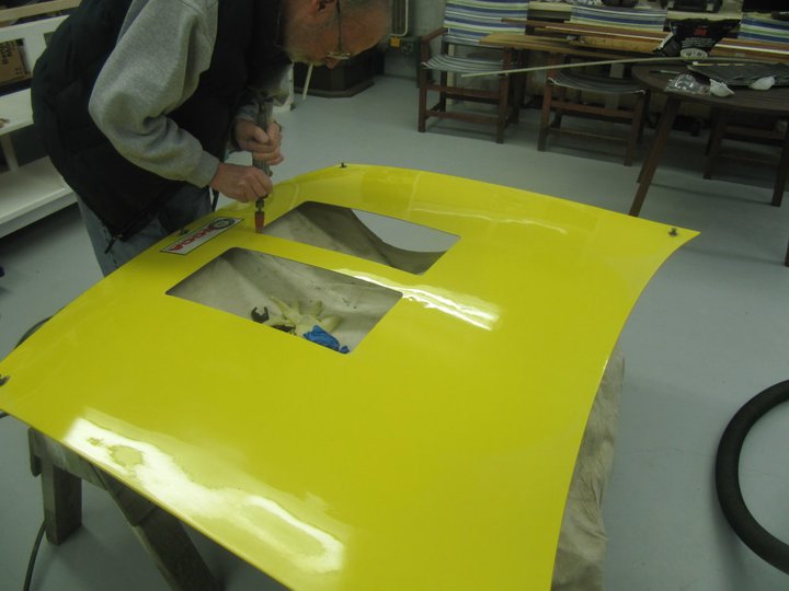
I took the hood up to JP's shop to make the cutouts. Fortunately I was able to get JP off his butt to help cut the hood. Notice that he can't do anything without a cig hangin out of his mouth. 
Here are the panels bonded to the back of the hood and in place on the car.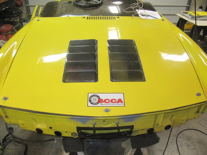
Side view, they are just under the 1" height restriction as per SCCA.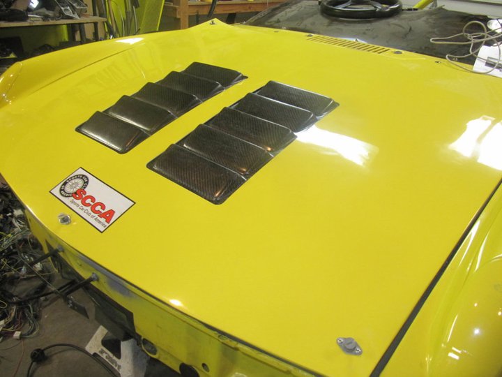
Looking down into the hood you can see the radiator and fan.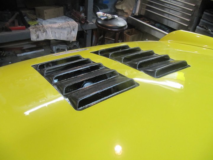
On the backside, you can see the area of the core mat we had to remove to bond directly to the backside of the hood. Added an additional layer of epoxy to the backside for strength.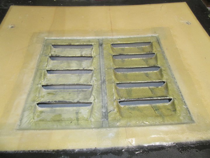
I also was able to put a gallon of fuel in and test the system...good idea that I did this now as I found a pinched injector o-ring and had to get a new set on order. It was fun to have 45psi of fuel squirting out of the fuel rail.
-Britain
Posted by: DanT Feb 7 2011, 11:15 AM
Hood came out nice Brit, even with JP doing the cutting
I have probably forgotten but where is the air coming in to the radiator from...?
Posted by: Britain Smith Feb 7 2011, 11:17 AM
Air entering the oil cooler cutout location in the front bumper.
-Britain
Posted by: sawtooth Feb 7 2011, 11:55 AM
Looking great Britain. Make sure, double sure to shoot some video of your car on the dyno for us, please?
Posted by: Andyrew Feb 7 2011, 12:25 PM
Is the radiator going to be shrouded to the vents? Just curious.
Were those louvers flexible to mold to the curve of the hood? Curious how you managed that.
Looking good as usual!
Posted by: Britain Smith Feb 7 2011, 01:06 PM
The recent change to the SCCA rules do not allow ducting from the radiator to the vent. I am still trying to clarify exactly what I can and can't do. As per the rules I also need to add a mesh screen under the louvers...again, trying to clarify.
As for the curve of the hood, the louvers were fairly flexible but I had to use a bunch of weights and some strong epoxy to get the shape right...took all weekend to set.
-Britain
Posted by: J P Stein Feb 7 2011, 01:09 PM
Is the radiator going to be shrouded to the vents? Just curious.
That touches a sore spot.
Believe it or not, per SCCA XP rules building a duct from the radiator to the vents/louvers is ILLEGAL! The result will be some trailer park engineering in an attempt to get the hot air out & away from the gas tank......

Posted by: Andyrew Feb 7 2011, 02:40 PM
Eek.
Personally I dont think that it will be enough heat (for autox) to cause any problems with the gas tank. But diverted air and keeping the engine cool enough is my concern. You could always open up the fenderwells (Unless thats against the rules as well). That combination would certainly keep the radiator cool, and maybe add in brake cooling (500+ deg brakes vs 150 deg air)
Posted by: grantsfo Feb 22 2011, 11:55 AM
Check this out! Its still being developed but when they figure out all the ECU mapping watch out! EMod Lotus Europa with 20B triple rotor turbo. Makes 440 WHP! It amounts to little more than a tubeframe car with fiberglass shell. inboard brakes, Penske dampers, fat Avon slicks.
Attached image(s)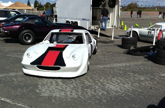
Posted by: Britain Smith Feb 22 2011, 11:59 AM
Yea, is that Jesus car? Looks pretty fast...glad it is in Emod.
-Britain
Posted by: grantsfo Feb 22 2011, 12:18 PM
Yea, is that Jesus car? Looks pretty fast...glad it is in Emod.
-Britain
No Jesus' car is in the background and is almost equally as fast.
Posted by: Britain Smith Feb 22 2011, 12:23 PM
Wow, there are 2 Europa's down there...nice!
-Britain
Posted by: Britain Smith Feb 22 2011, 12:38 PM
I haven't been posting progress picture as often, but I can promise you I have been working hard. I had to move my dyno time out a week due to a delay in the arrival of the custom flywheel, but now I am back on track.
All the car wiring is completed. Pictures of wiring is not that exciting, but here is the ECU and rear fuse panel wired up.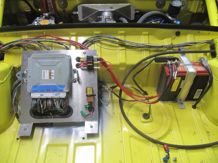
This is the custom flywheel that I commissioned WEVO to make. I had a concern about the conversion flywheels out there as they are welded together, about 32lbs with the pressure plate assembly, and intended for a 6200rpm USDM motor. This is an 8500 rpm engine and I wanted a little bit lighter rotating mass....therefore I went this route.
The flywheel is actually a three-piece design. This the flywheel as it arrived.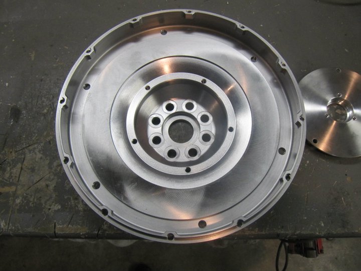
This is the back mounting flange of the flywheel. The large step is required to clear the adapter plate. This is where the conversion flywheels are welded.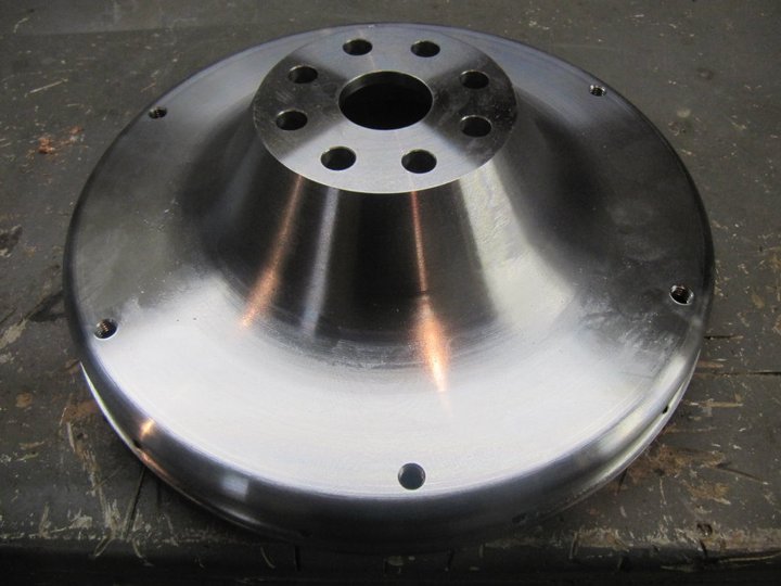
Ring gear installed.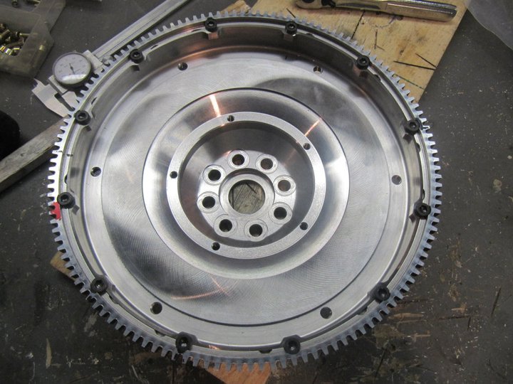
Flywheel mounted on the engine and the pilot bearing plate fitted.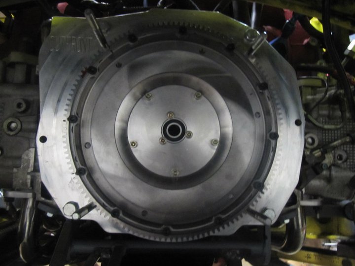
Tilton pressure plate installed.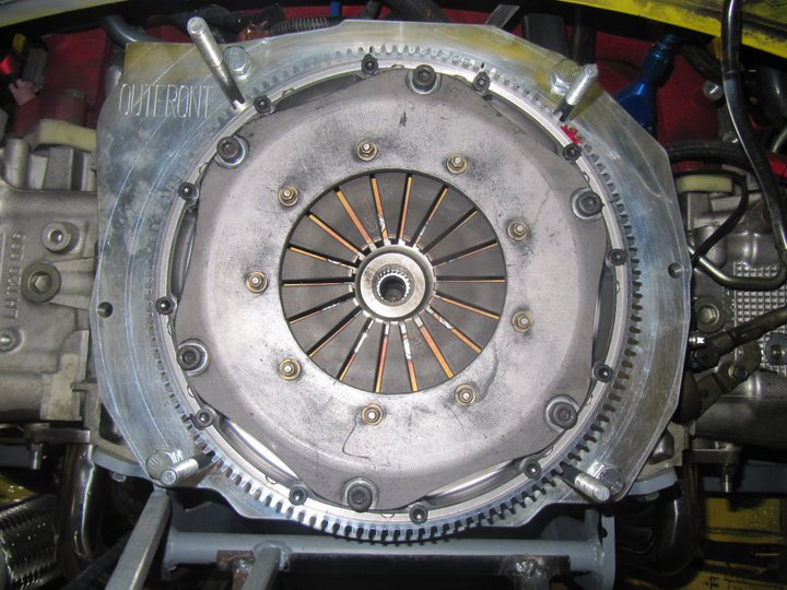
As I mentioned when installing the pedal assembly, I decided to go with a hydraulic throw-out bearing. Here is the Tilton Hydraulic throw-out bearing assembly fit in the 901 transmission. This is a completely custom set-up with custom parts. It is actually a SAAB bearing.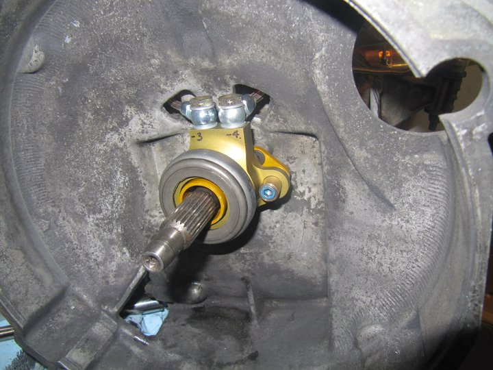
And finally, the transmission reinstalled with the assistance of my wife. VSS sensor wired up and hydraulic lines routed.
I actually filled the engine with oil/water last night and cranked it over. I got it to start for about 5secs before it would stumble. I have some ideas on things to check, but the good news is that is started. It was about 11:30 last night when I was cranking it and decided that I didn't want to push it with the neighbors, I will try again this evening.
-Britain
Posted by: grantsfo Feb 22 2011, 12:55 PM
Wow, there are 2 Europa's down there...nice!
-Britain
Yeah Emod is actually a viable class here this year. AAS event this year in July should be a great shootout between these Lotus cars and the V8 and turbo Rotory powered Austin Healys. The AAS memorial event attracts very fast cars. I'm going for sure this year. I think California will have 4 or 5 e mod cars that are cable of winning nationals this year.
Cant wait to see your car run! Looks great from the pictures. I hear you on the crazy SCCA rules. I despise SCCA rules and cant understand some of the people involved in the process. Some of the stuff makes no sense. Especially when talking venting etc. I couldn't touch any chassis metal from what I read. And when I asked for rulings on my center radiator the best I ever got was something like. "well that is probably OK" Never get a commitment.
Now I'm trying to get Street Prepared classing for the 370Z it is a joke. Takes weeks to months. One might expect that a moderate volume sports car that has been on the market for almost 3 years might have been classified! The politics behind car classing are amazing to me. I have to run in same class as professionally prepared Z06's and GT2's in a car that makes 316 WHP and weighs 3300 lbs. Yet EVO that makes 450 WHP can hang in BSP and dominate the class. I love UFO. I called them compared car to other BSP cars and they agreed and allowed BSP classing in one day. Gotta love effectiveness of one person in charge!
Here is my new ride.
Attached image(s)
Posted by: Britain Smith Feb 22 2011, 01:50 PM
Yea, I have several letters in for SEB clarification. Depending on my schedule, I might be able to make a California AAS event....we shall see.
-Britain
Posted by: Britain Smith Feb 22 2011, 11:25 PM
IT'S ALIVE!!!!
First start of my Subaru engine conversion. Still a couple of things to sort out, but I am 99% of the way there. Dyno time in less than a week.
http://www.youtube.com/watch?v=2E0RPBTWZaQ
https://www.youtube.com/watch?v=2E0RPBTWZaQ
Posted by: DanT Feb 22 2011, 11:29 PM
sounds good Brit
any leaks or such?
Posted by: Britain Smith Feb 22 2011, 11:30 PM
Yea, the turbo drain return line is leaking...I will address that tomorrow. Other than that, it is all good.
-Britain
Posted by: Hontec Feb 23 2011, 01:59 AM
Congratulations! you've been working hard for it!! 
Posted by: cary Feb 23 2011, 06:43 AM
Nice.
Posted by: Randal Feb 23 2011, 09:45 AM
Man, we have to nominate you for mechanical genius/ race car builder of the year!
I can't imagine how exciting it must have been to turn that puppy over the first time after all that work. Sounds wonderful.
Looking forward to seeing you driving in Medford.
Posted by: Randal Feb 23 2011, 09:48 AM
Who is your secret low cost vendor for all those hose ends?
I quit counting all the ones you've installed on your car.
Posted by: McMark Feb 23 2011, 10:59 AM
Awesome! Can't wait to see it in Medford. I embedded your video for you. 
Posted by: Britain Smith Feb 23 2011, 11:37 AM
Who is your secret low cost vendor for all those hose ends?
I quit counting all the ones you've installed on your car.
Hey Randal, I got all the hose ends and startlite hoses from http://www.aeroquip.cc. Their prices for the startlite hoses are cheaper than the normal stainless hose at Summit. I wish I had found them a bit earlier in the build, but I got most of the stuff there.
On starting the engine...I actually tried the night before but it would only start for about 2secs and die. Talking with the Suby experts (Kent Porter), they recommend unplugging the MAF and O2 sensors so that the ECU goes to a default table...started right up. I then flipped the MAF around and tried again and it started right up. The MAF is key'ed on the intake pipe, but I had the intake pipe facing the wrong direction.
-Britain
Posted by: PeeGreen 914 Feb 23 2011, 11:49 AM
I can't wait to see how you do this year. It's a tough class but you were looking good last year with what you had. Now you have an even better power to weight.
Are you taking the car to the big show this year?
Posted by: Britain Smith Feb 23 2011, 12:03 PM
Are you taking the car to the big show this year?
That is the plan...gotta represent my sponsor http://www.where2race.com
-Britain
Posted by: PeeGreen 914 Feb 23 2011, 12:04 PM
Sweet
Posted by: JRust Feb 23 2011, 12:31 PM
Yeah checked out the video on FB last night. Sounds great Brit! I can't wait for the dyno day video 
Posted by: Britain Smith Feb 23 2011, 12:38 PM
Yea, just got a call from the tuner...Monday is a no go for him. Therefore, it will be some other day next week...no problem, that will give me a bit more time to sort things out.
-Britain
Posted by: 69dblcab Feb 25 2011, 05:38 PM

You Have been presented with this trophy, in honor of the awesome subie build documentation.
I stumbled and got stuck here.
Thanks for the Motor mount ideas for my vanagon subie conversion #2.
I really like my first one. 2.2 in an a Doublecab. What an improvement!!
A learning point. I hope you donor was a standard transmission.
The autos have no power below 2,500rpm then they come on. Don't ask how I know this. 
I will check in periodically. I hope you and your son have a great season.
Cheers
Dudley
Posted by: Britain Smith Feb 25 2011, 05:48 PM
Thanks Dudley.
Right now I am delayed a bit waiting on parts. During the first start-up, I determined that there was an oil leak in the turbo drain as a result of the position of the turbo. There are two problems with the position of the turbo, first of all it is a little too low in relation to the oil pan. This is not an issue during normal operation, but during start-up or shut-down the accusump takes in another 2 quarts of oil. If it is not operated properly, then that oil is in the block and potential filling the turbo and could ruin the turbo. The second problem is the turbo drain flange that I made is not perfect flat and leaks.
To alleviate the problem, I have ordered a scavenge pump from www.turbowerx.com and all the associate AN fittings from www.aeroquip.cc and it should all arrive next week. It should be a straight forward install and a little extra wiring. Dyno time has been pushed a week to sort out this problem. Everything else on the car seems to be working properly at this point.
-Britain
Posted by: bfrymire Feb 25 2011, 07:33 PM
Thanks Dudley.
Right now I am delayed a bit waiting on parts. During the first start-up, I determined that there was an oil leak in the turbo drain as a result of the position of the turbo. There are two problems with the position of the turbo, first of all it is a little too low in relation to the oil pan. This is not an issue during normal operation, but during start-up or shut-down the accusump takes in another 2 quarts of oil. If it is not operated properly, then that oil is in the block and potential filling the turbo and could ruin the turbo. The second problem is the turbo drain flange that I made is not perfect flat and leaks.
To alleviate the problem, I have ordered a scavenge pump from www.turbowerx.com and all the associate AN fittings from www.aeroquip.cc and it should all arrive next week. It should be a straight forward install and a little extra wiring. Dyno time has been pushed a week to sort out this problem. Everything else on the car seems to be working properly at this point.
-Britain
Dyno time:
(And that should read ANXIOUSLY.)
-- brett
Posted by: d914 Feb 25 2011, 07:49 PM
Small thought,, The stock angle of the suby motor and tranny have considerable angle towards the back. Outfront has stated that they made a oil pan with different kickouts for the midengine configurations.. For the longest time I saw no need or reason....but I believe Sawtooth ran into some small issues with this on his tranny..again do to our level install.. He added more oil and another filler plug to the tranny.. I now understand what Outfront was talking about.. I see that you have the accusump but thought I'd let you know considering how hard this car will be driven.
Posted by: Britain Smith Feb 25 2011, 10:55 PM
Yes, I am aware of the stock angle of the Subaru engine. In fact, I have raised the front of the engine as much as I improve the ground clearance of the stock oil pan and the header that I am running. I have not heard good things about the Outfront shortened oilpan for high-g applications and therefore wanted to stay away from a super-short oil pan. I might be fabricating my own oil pan down the road, but we shall see.
-Britain
Posted by: d914 Feb 26 2011, 09:49 AM
cool,, but not there shortened pan,, they have a MId engine pan,, its not pictured, but I have seen at there shop.. sounds like you have it covered,, back to trying to get mine done!!!
Posted by: Britain Smith Feb 26 2011, 11:16 AM
Their midengine pans is shortened as well I believe. If you have a picture, show it here.
-Britain
Posted by: Zaney Feb 26 2011, 06:13 PM

Brit,
In your ECU and wiring install, could you expand what the rear fuses are used for? I am trying to finalize the suby wiring on my engine with the stock ECU and would like to cross reference with your wiring.
BTW, your setup is amazing! Thanks for all the pics!
Cheers  ,
,
Nate
Posted by: Britain Smith Feb 26 2011, 06:20 PM
Hey Nate...I need to update my diagrams for the stuff that I have added, but I can send all my diagrams to you if you would like.
From memory, the top 2 fuses are +12V from the battery and send power to both the ECU and the main relay. The bottom 3 fuses are switched 12V from the ignition switch and go to the ECU, coils, VSS (vehicle speed sensor), and NPS (neutral position switch).
-Britain
Posted by: 69dblcab Feb 27 2011, 09:16 AM
Britain,
In regards to the turbo.
If you are feeding High pressure oil to the bearing and then dumping that to the Low pressure sump. Does it really matter if it does not gravity drain.
The only possible issue as I see it would be coking the bearing in the turbo due to no cool down time prior to shut down.
The leak I understand just not the added complication of scavenge pump and its associated plumbing.
Posted by: J P Stein Feb 27 2011, 09:57 AM
Britain,
In regards to the turbo.
If you are feeding High pressure oil to the bearing and then dumping that to the Low pressure sump. Does it really matter if it does not gravity drain.
The only possible issue as I see it would be coking the bearing in the turbo due to no cool down time prior to shut down.
The leak I understand just not the added complication of scavenge pump and its associated plumbing.
I would tend to agree with you, however, I'm not expert on turbos, Subies, and their innerworkings. Brit's gurus on this seem to think that I could result in blown turbo seals. I am one skeptical, cynical SOB and have seen enough "gurus" on the Porsche side of the house to last me a lifetime. Without empirical info I can't say they're fulla crap so to be extra safe the smart money is to go with them....untill ya *know* different......and , of course, they are not spending my money.
I *think* part of the problem is the drain line he installed is not made to be pressurized.....even a little bit.
Posted by: Britain Smith Feb 27 2011, 11:17 AM
Britain,
In regards to the turbo.
If you are feeding High pressure oil to the bearing and then dumping that to the Low pressure sump. Does it really matter if it does not gravity drain.
The only possible issue as I see it would be coking the bearing in the turbo due to no cool down time prior to shut down.
The leak I understand just not the added complication of scavenge pump and its associated plumbing.
You are correct, the drain line is a gravity drain. However, if the drain line is filled with oil then there is no where for the oil to gravity drain into. My issue is that the height of the turbo in relation to the oil level is marginal at best. Any situation where the oil level raises (i.e. when the accusump is opened, or the car is started on a downward angle) then the turbo will be filled with oil and could result in damage to the turbo. On a seperate note, the drain line I had made leaked and was not an ideal solution.
-Britain
Posted by: Britain Smith Feb 27 2011, 11:55 AM
I am working to finish everything up before receiving the oil scavenge pump and getting this thing on the dyno.
First thing was to add a additional switch for the oil scavenge pump and while I was there, I added labels for the confused.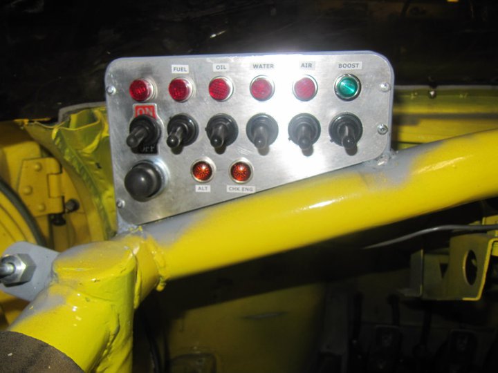
Shifter installed and functioning.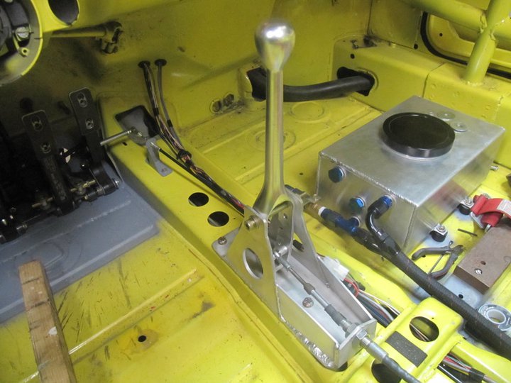
I installed a Hall Effect Sensor under the shifter and a magnet in the shifter to detect Neutral Position for the ECU. The red LED indicates that is it aligned.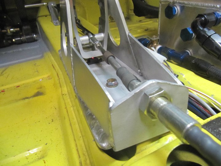
Hall Effect Sensor installed on the CV to pick up Vehicle Speed.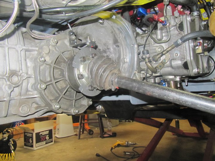
In full droop, the axle doesn't hit the exhaust pipe. WIN!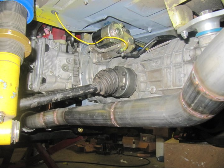
ECU fully wired up and wires secured.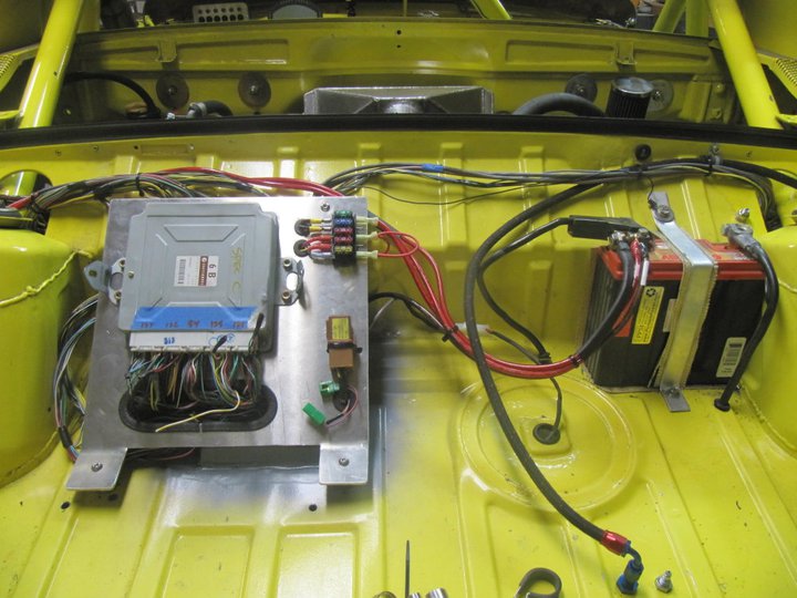
Oil filter sandwich plate with Oil Temp Sensor.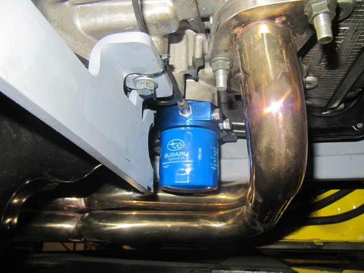
In-line water temperature sensor.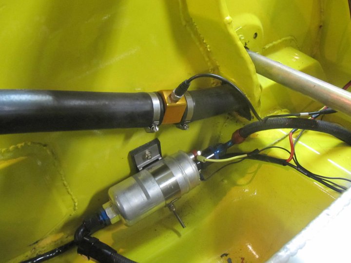
The scavenge pump and the associated AN lines and fitting should all be here by Thursday. That gives me a week to sort everything out before the dyno tuning.
-Britain
Posted by: McMark Feb 27 2011, 12:16 PM
Where did you get your Hall Effect sensors? I like those with the LED.  Love the neutral sensor.
Posted by: Britain Smith Feb 27 2011, 12:21 PM
Got the sensors from: http://www.digikey.com/
55110-3H-02-A-ND SENSOR HALL EFFECT W/LED PNL MNT
Posted by: Britain Smith Feb 28 2011, 03:43 PM
Ah man it is frustrating to wait on parts to arrive
Guess I will go work on my site: http://www.where2race.com
-Britain
Posted by: jpnovak Mar 1 2011, 10:42 AM
Britain,
Your project is really progressing nicely. You have given me new motivation to complete my GRM Challenge car. I was stuck at where to mount the ECU. I cut the rear trunk out of my car so the intercooler will stay in the stock location and flush up against the rear decklid. I am going to mount the ECU in the trunk in a plastic housing to protect it against the elements.
Where did you find the inline temp sensor? That looks like a nice piece.
Posted by: Britain Smith Mar 1 2011, 12:10 PM
I got both the sandwich adapter and the inline water temp adapter from Prosport.
http://prosportgauges.com/water-temp-sender-radiator-hose-adaptor.aspx
-Britain
Posted by: Britain Smith Mar 4 2011, 01:50 PM
Got the Turbowerx scavenge pump and associated AN fitting in the mail yesterday and got them all install. Due to space limitation and rules around the size of holes allowing in the firewall, I chose to plumb this up using bulkhead fittings. The turbo drain is now connected on one end and pump oil back into the oil pan. Few wires to hook up and the system is working perfect.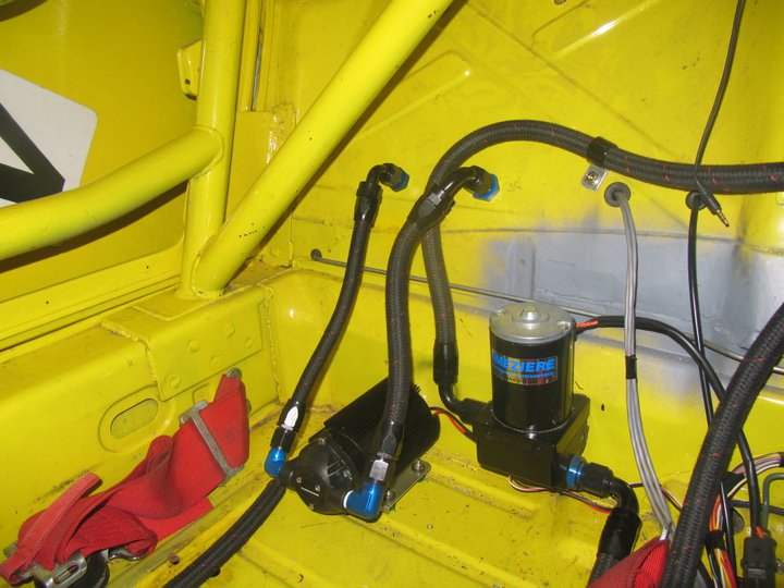
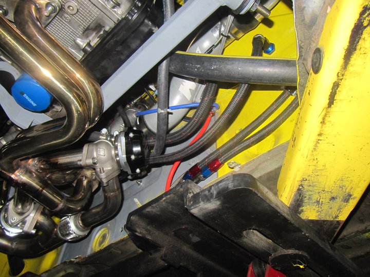
Still working on understand the coolant system, for some reason I don't think I am getting water to circulate properly. I will troubleshoot more this evening.
-Britain
Posted by: Randal Mar 4 2011, 01:56 PM
Pretty cool Britain. What a huge job! But on your first run it'll all be worth it.
Posted by: J P Stein Mar 5 2011, 06:28 PM
Watched Brit drive the shitbox (or whatever he's calling it) up and down his street today. With the tall first gear (F) & light flywheel he kilt it 2-3 times trying to get it moving .....when he finally got it the tires were chirping. A few half throttle pases down his street left loooong black marks when the turbo kicked in.
He has a couple problems to solve, but it's stout.....oh, excuse me.....it's AWESOME!!!  ...he said I wasn't excited enough.
Posted by: JRust Mar 5 2011, 07:36 PM
I can't wait to see the video
Posted by: Britain Smith Mar 5 2011, 07:45 PM
Alright, world premier. The car is officially off jackstands and driving under it own power. The throttle is a light switch, the acceleration is unbelievable, and the hydraulic clutch assembly is perfect. Gotta fix a water leak on the coolant line coming out of the turbo and need to determine why so much oil is coming out of the muffler...most likely due to the issues I had with the turbo drain or overfilled from the accusump. Either way, it will be ready for the dyno on Monday.
Check out the video...
http://www.youtube.com/watch?v=Cbhc_2y2lYU
https://www.youtube.com/watch?v=Cbhc_2y2lYU
-Britain
Posted by: Britain Smith Mar 5 2011, 07:51 PM
BTW, that wasn't even full throttle in the video...I tried full throttle once and the back end jumped out on me...perfect!
-Britain
Posted by: Scarlet75 Mar 5 2011, 07:57 PM
Posted by: Rand Mar 5 2011, 08:12 PM
Now it is the "oh shit" box.
Or you could name it after the expletives the neighbors up and down the street shout as you razzzz by.
LOVE it. Congrats man. Awesome to see it running. Hope dyno Monday goes well.
Posted by: DanT Mar 5 2011, 09:29 PM
JP didn't even need to light up.....just inhale
nice job Brit....no mosquitoes in your neighborhood today.
Posted by: Britain Smith Mar 5 2011, 09:49 PM
JP didn't even need to light up.....just inhale
nice job Brit....no mosquitoes in your neighborhood today.
Ha!
Yea, gotta get the smoke plume down.
-Britain
Posted by: Zaney Mar 5 2011, 09:59 PM
Awesome
This engine combo is leading the pack in the Teener conversions! Now we need Amenson to get his Sti 914 going 
Cheers
Nate
Posted by: Britain Smith Mar 7 2011, 01:05 AM
The car is officially ready to go. All the body panels on, fluids in, and everything checked. Just gotta load her up and take her to Dr. Bailey at Cobb Tuning Surgeline in the morning.
All the body panels on.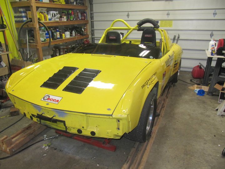
Engine lid fits with no issues.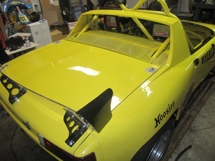
Passenger seat in and waiting for Dr. Tim Bailey at Cobb Tuning Surgeline to work his magic.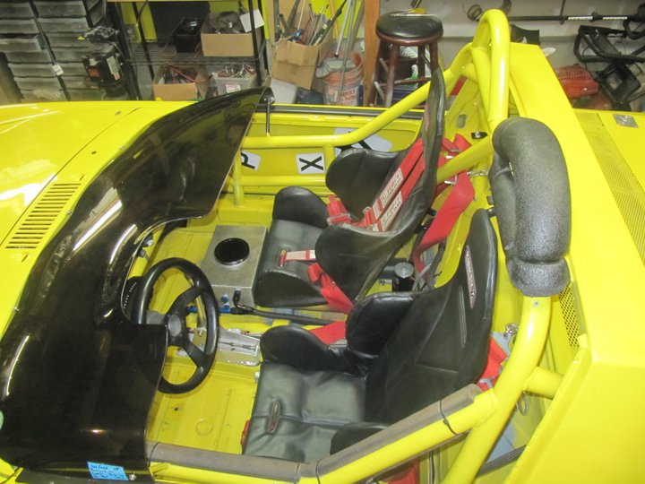
We shall see how it goes.
-Britain
Posted by: sawtooth Mar 7 2011, 02:05 AM
Congrats! First drive is the best ever. Man you have tolerant neighbors, I'd be strung up for that kind of behavior in my neighborhood.
Posted by: BMXerror Mar 7 2011, 10:53 AM
Mark D.
Posted by: Andyrew Mar 7 2011, 11:35 AM
That is QUICK!
Congrats!
Looks like great spool on that turbo! JUST what you want.
Posted by: Randal Mar 7 2011, 12:03 PM
Congratulations Britain. That was only partial throttle.... Wow.
Bigger slicks on order?
Hell if you get that thing to hook up, you'll have to get a Hans device.
Posted by: Britain Smith Mar 8 2011, 12:18 AM
Spent the entire day today at Cobb Tuning Surgeline getting my car sorted out by Tim Bailey and the crew. Those guys are great and are very knowledgeable even though I tried to bring them the most off the wall project that I could come up with. They went above and beyond to understand the issues that we encountered and did not once complain or make comments about any of the work that I had done. Very professional shop that I would highly recommend to anyone.
Now...to describe the day. I arrived early and got my car strapped in to the dyno and immediately had some issues to address. First off was a bad MAF causing an surging idle. Got that replaced and then spent quite a long time trying to understand why my AIM dash would communicate with the ECU but the EcuTek cable would not seem to connect. Ended up being a ground wire that I for some reason forgot to actually hook up.
After that, we spent some time getting the air in the coolant system burped out after I replaced the coolant lines running to and from the turbo. Then, we got to actually run the thing on the dyno and determined that the boost controller wasn't functioning properly and went thru replacing boost lines and replumbing the controller. Things were looking good until at the very end the AVCS (variable cam timing) stopped functioning because the neutral position switch and the vehicle speed sensors both stopped working.
Even though we had issues, Tim was able to work his magic on a first pass tune and the car made 330hp and 285ft-lbs at 14psi without AVCS. I will spend the week understanding the faults and get back up there for another pass. I also bought some larger injectors so that we can convert over to E85 and I won't have to buy anymore 110octane leaded race fuel.
Here is a video of one of many dyno pulls that were completed.
http://www.youtube.com/watch?v=r2zq8AcZHcA
https://www.youtube.com/watch?v=r2zq8AcZHcA
-Britain
Posted by: Andyrew Mar 8 2011, 12:37 AM
Dyno sheet? Those are some respectable numbers!! Congrats!!
Posted by: Britain Smith Mar 8 2011, 12:39 AM
Didn't get them tonight...should get a copy tomorrow. They aren't the final numbers, just a start. The coolest thing is that this is 2.0L motor....and it doesn't leak any oil
-Britain
Posted by: pktzygt Mar 8 2011, 07:48 AM
Impressive! I'm doing a JDM ej20g with a ball bearing turbo and the good heads that the shop I'm working with predicted upper 200 hp range with low boost. I'm anxious to see what yours will do with pump gas.
Posted by: Randal Mar 8 2011, 11:37 AM
Spent the entire day today at Cobb Tuning Surgeline getting my car sorted out by Tim Bailey and the crew. Those guys are great and are very knowledgeable even though I tried to bring them the most off the wall project that I could come up with. They went above and beyond to understand the issues that we encountered and did not once complain or make comments about any of the work that I had done. Very professional shop that I would highly recommend to anyone.
Now...to describe the day. I arrived early and got my car strapped in to the dyno and immediately had some issues to address. First off was a bad MAF causing an surging idle. Got that replaced and then spent quite a long time trying to understand why my AIM dash would communicate with the ECU but the EcuTek cable would not seem to connect. Ended up being a ground wire that I for some reason forgot to actually hook up.
After that, we spent some time getting the air in the coolant system burped out after I replaced the coolant lines running to and from the turbo. Then, we got to actually run the thing on the dyno and determined that the boost controller wasn't functioning properly and went thru replacing boost lines and replumbing the controller. Things were looking good until at the very end the AVCS (variable cam timing) stopped functioning because the neutral position switch and the vehicle speed sensors both stopped working.
Even though we had issues, Tim was able to work his magic on a first pass tune and the car made 330hp and 285ft-lbs at 14psi without AVCS. I will spend the week understanding the faults and get back up there for another pass. I also bought some larger injectors so that we can convert over to E85 and I won't have to buy anymore 110octane leaded race fuel.
Here is a video of one of many dyno pulls that were completed.
http://www.youtube.com/watch?v=r2zq8AcZHcA
-Britain
Sounds like you had the right team working on the project.
How many of the "issues" you encountered could be figured out electronically or was it primarily just the combined experience in the room that help to figure out what was not working? I mean the idle issue is pretty easy to recognize, but how do you know you have air in your coolant lines? And how can a coolant line be bad? What happens when the AVCS stops working? And you made 330 HPRW without it. Wow.
That motor is gong to be a barn burner.
Sorry about all the questions, but your project is fascinating.
You ought to come down for the Ashland Hill Climb. With that motor you'll be King of the Hill.
Posted by: Britain Smith Mar 8 2011, 03:44 PM
Hey Randal.
To answer your questions.
1. The electrical issue was 1 ground wire that I forgot to hook up back at the ECU, that was my fault and was fairly simple to find once we determined that the pin required ground.
2. The bad coolant line was found because there was a large coolant leak under the car after the engine was warmed up. This was due to the ID of the hose being slightly larger than required and poor quality hose clamps. I replaced the line with slightly smaller ID (think standard vs metric hose) and better hose clamps.
3. For air in the coolant system, the engine temp went from 140 to 240 within about 10secs. At this point the sensor was actually reading steam and giving bad values. It also took a while to purge the air in the entire system to the front of the car and back.
4. The AVCS requires a neutral position switch and a vehicle speed sensor to function properly. When the hall effect sensors that I had installed stopped working then the AVCS stopped working. The AVCS is variable cam timing which allows the engine to achieve full boost earlier in the rpm range. With the AVCS, full boost was achieved around 3200rpm or so. Without AVCS, full boost did not come in till about 4000-4500 rpm and the is a drop in the torque. With the AVCS, the torque value will be very similar to the HP value
-Britain
Posted by: Andyrew Mar 8 2011, 03:54 PM
That sounds a lot like the issue I had on my setup on my Audi. When I first installed a big turbo I was getting full boost at 4700rpms. When I finally installed a electric boost controller and some other do dads I got full boost at 3200. Gave the car a whole different feel, just way more usable power.
Posted by: BMXerror Mar 9 2011, 09:42 PM
Great opening numbers, Brit! Are you looking to push any more boost with E85? BTW, where are those dyno sheets. Let's see that torque curve. Great progress. I'm looking forward to watching her run at Lincoln this year. Keep up the good work.
Mark D.
Posted by: Britain Smith Mar 9 2011, 11:08 PM
Hey Mark. I don't have the torque curves on hand and they would not be that beneficial because in the final pulls the AVCS was not functioning properly. I think I have fixed it this evening and I will test it tomorrow. Hopefully I will make it back on the dyno soon.
-Britain
Posted by: plays with cars Mar 9 2011, 11:58 PM
Hmmmm.... 1700lb car + 330whp motor = 

 and a whole bunch of other fun smilies.
That is going to be one fun ride!
Posted by: DukeTrout Mar 11 2011, 03:26 PM
4. The AVCS requires a neutral position switch and a vehicle speed sensor to function properly. When the hall effect sensors that I had installed stopped working then the AVCS stopped working. The AVCS is variable cam timing which allows the engine to achieve full boost earlier in the rpm range. With the AVCS, full boost was achieved around 3200rpm or so. Without AVCS, full boost did not come in till about 4000-4500 rpm and the is a drop in the torque. With the AVCS, the torque value will be very similar to the HP value
-Britain
Or more, especially with E85. The 2.5 motor is a little torquier than the 2.0, but it's pretty common to have tuned suby engines with 10-15% higher peak torque than peak hp. With AVCS active you may not get much more hp, but expect torque to peak in that 3500 rpm range where full boost hits.
Posted by: ChrisNPDrider Mar 11 2011, 04:08 PM
What's up with the Subby conversion guys posting burn-out videos?
IT"S NOT FAIR!
I am looking forward to seeing the round 2 dyno info w more of the bugs worked out
Posted by: Britain Smith Mar 11 2011, 05:09 PM
Round 2 on Monday afternoon. The speed sensor is fixed, the neutral position sensor is "tricked" and the larger injectors will go in on Sunday in preparation for E85.
Not looking to make much more power, just want to complete the tuning and ensure that all systems are a go.
-Britain
Posted by: DBCooper Mar 14 2011, 06:52 PM
Like a light switch, huh? I told you you were going to have to re-learn some things to go fast in a turbo car. Ask Alain Prost. Funny thing is you didn't SEEM like a crazy man, but from this thread it's obvious you are. And that JP guy, he's having almost as much fun egging you on as you're going to have aiming that thing and pulling the trigger. Cool. Very well done. I'm a fan.
Posted by: BMXerror Mar 14 2011, 07:52 PM
...Funny thing is you didn't SEEM like a crazy man, but from this thread it's obvious you are...
It's the quiet ones you've gotta worry about.

Well, how did it go today? The 'World is dying to know.
Mark D.
Posted by: Britain Smith Mar 14 2011, 11:41 PM
Went well. Still dealing with boost controller issues and wheel slip on the dyno making it difficult to tune properly, but the car is now running on E85 and it the craziest thing I have ever driven at speed.
-Britain
Posted by: DanT Mar 14 2011, 11:50 PM
details
Posted by: Downunderman Mar 15 2011, 12:21 PM
You should keep a close eye on your fuel plumbing and fuel pumps using that stuff. The V8 Supercars use it down here because it's so "green", but they regularly replace lift pumps and high pressure pumps because the fuel destroys all the rubber bits and seals.
I was in NZ looking after as friend's historic car at the Bruce McLaren Festival last year, and the fuel supplier unfortunately supplied E25 instead of AvGas and didn't tell anyone. The fuel dissolved the foam in bladder tanks and everyone with Lucas injection had to replace every seal. The fuel even pissed out of one metering unit enough to set a car on fire. All manner of problems ensued. The litigation is ongoing.
We weren't so lucky, detonated Repco Brabham motor which required two new cylinder heads.
Cheers,
Posted by: Britain Smith Mar 15 2011, 02:52 PM
Howard....thanks for that tip. I built the entire fuel system to be compatible with E85, but I didn't think about the foam inside the tank. I just called RCI where I got the foam that they indicated that it will break down and shouldn't be used with E85. Now I need to find a safety foam that is compatible...any suggestions?
-Britain
Posted by: messix Mar 15 2011, 03:34 PM
Howard....thanks for that tip. I built the entire fuel system to be compatible with E85, but I didn't think about the foam inside the tank. I just called RCI where I got the foam that they indicated that it will break down and shouldn't be used with E85. Now I need to find a safety foam that is compatible...any suggestions?
-Britain
Check with a sprint car supply
Posted by: Downunderman Mar 16 2011, 12:12 PM
I would try ATL. I'm off to Phillip Island this afternoon for the big historic meeting with the same car, it only took 15 months to have new heads cast, machined and installed.
Posted by: Downunderman Mar 16 2011, 05:12 PM
Bugger, heads are porous. Now spectating.
Posted by: bfrymire Mar 28 2011, 11:43 PM
Britain,
When is your first autocross? I am really curious about what this is going to be like. For instance, does the boost hit in the right place (If not linear, could be a real surprise when boost come on.)? Does it come strong out of the corner, and what is it like off throttle entering a corner.
I have always done NA for autocross, as the turbo guys had a handfull.
-- brett
Posted by: FourBlades Mar 29 2011, 07:11 AM
Very educational build.
Take off the spoiler, get a different tranny and you may have a Land Speed Record car...
John
Posted by: Britain Smith Apr 7 2011, 12:35 AM
Few updates.
I was having some issues with the Vehicle Speed Sensor set-up. I did a sort of shotgun approach to addressing the issue. I converted from a solid state hall effect sensor with the magnets in the trigger wheel to a proximity sensor and a notched trigger wheel. I also installed an ignition relay for the rear fuse panel instead of running straight through the master switch. I believe that I was getting voltage spikes when starting the car which may have cause premature death of the sensor. Either way, the combination proved reliable and ran all weekend without issues.
Here is the new Vehicle Speed Sensor installed with trigger wheel that I had cut on on the waterjet. 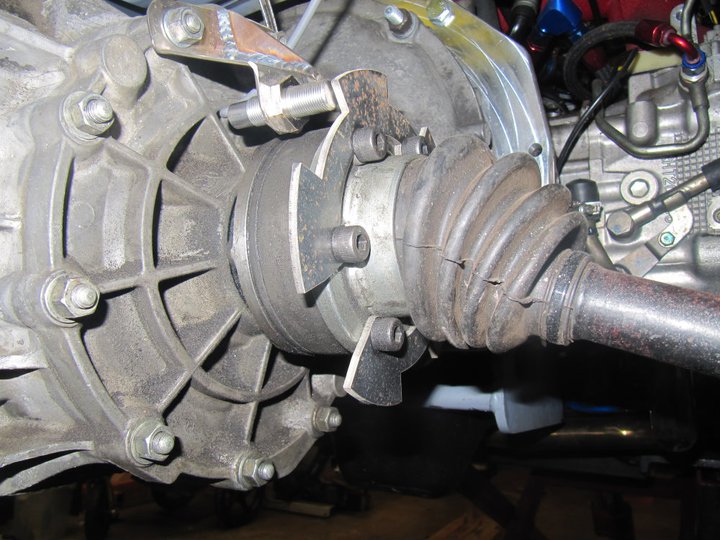
Clearance between the VSS and the trigger wheel. Spec is 1.5mm and because it is threaded, it is fully adjustable.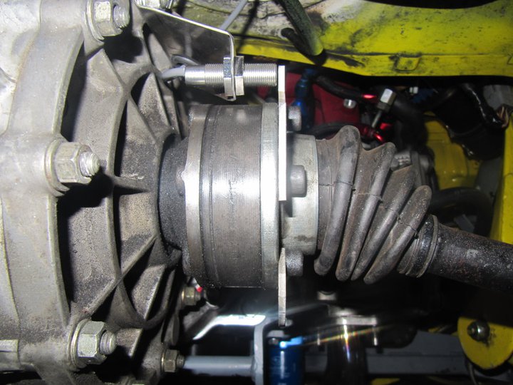
Also installed a pair of Tilton master cylinders. Previous set-up was 22mm front/19mm rear and the pedal pressure was significantly too high. New set-up is 18mm front/16mm rear which is still a bit high, but much more manageable. I currently run 911S aluminum front calipers, but I plan to switch to boxster calipers in the future.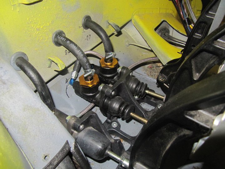
Ran the car this past weekend at a Test and Tune event in Eugene. Mixed weather conditions made set-up difficult, but we got some good shake down runs in without any major issues. Need some more time to get the brake bias correct and we had a slight issue with the hydraulic clutch, but I suspect it needs to be bled better.
Just in case there was any question...the car is much faster than it used to be.
I will get some video and pictures at the next event when I am not spending all my time working on the car.
-Britain
Posted by: cary Apr 7 2011, 06:54 AM
Congrats on the progress.
Posted by: J P Stein Apr 7 2011, 07:53 AM
Congrats on the progress.
Yeah, it'd be great if he could find a dry parking lot.
Ain't spring in the PNW great? I retired for ths shit?
Posted by: Walter Apr 7 2011, 11:15 AM
Nice speed sensor solution Britain!
Most use the sensor on the front axle with a RWD car though; just be mindfull reading it when you've experienced some rear wheel slip ;-)
Posted by: Britain Smith Apr 7 2011, 11:29 AM
Yes, but in this case the actually speed is relative as the ECU just needs to know that the car is moving in order for the active valve timing to engage.
-Britain
Posted by: DBCooper Apr 26 2011, 03:51 PM
And... how's it all going?
Posted by: Britain Smith Apr 26 2011, 05:37 PM
All is going well actually...thanks for asking. I guess it is time for an update.
I ran the car the weekend before last and although it was very fast, I still have a few items to get sorted out.
First of all, here are some cool pictures taken at the event: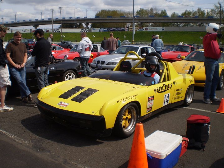
This seems to be the never ending story when running a prepared/modified car...working underneath the car.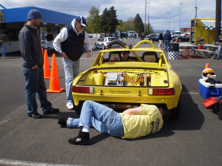
My co-driver clipping an apex cone: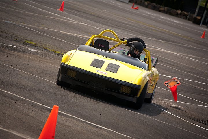
Me in the same corner with a little bit of rear brake lock-up.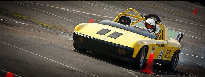
Also, here is a video of one of my runs.
http://www.youtube.com/watch?v=pFjPYWhQ1fE&feature=youtu.be
If you watch closely you can detect the two main issues while driving the car.
First, the car was making way too much power for the cold weather, old tires, and crappy asphalt surface. Just before this event I installed a separate boost gauge to monitor pressures and it was reading 14psi which is double what my low boost setting is supposed to be at. I have recently installed a Turbosmart e-boost electronic boost controller so I can tune the boost curves and accurately set the boost value based on the driver and surface conditions. I also replaced all the silicon boost lines with proper AN-4 fittings and line. I will be on the dyno at Cobb Tuning Surgeline next Thursday to dial it in.
Here is a picture of the new Turbosmart e-boost controller: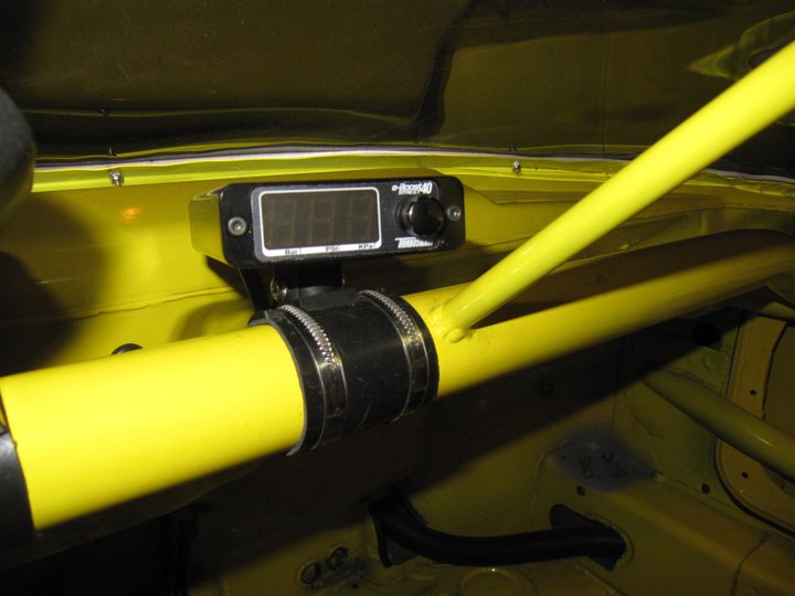
Here is a picture of the solenoid in the engine compartment: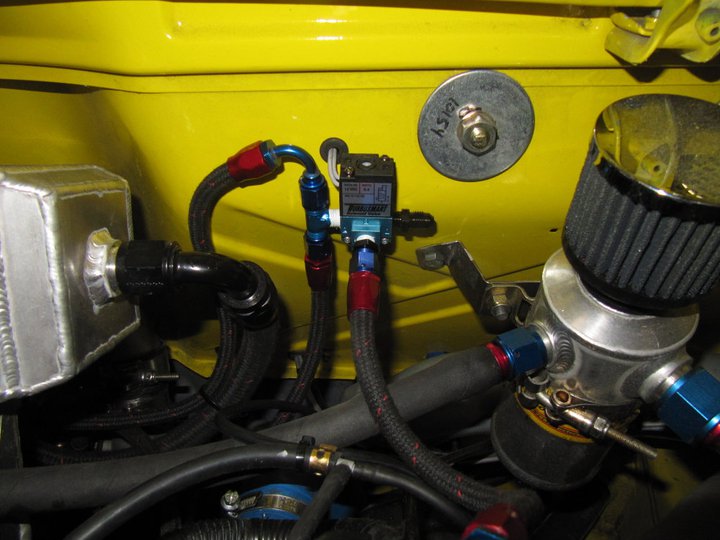
The second issue I was experiencing was brake balance. At every hard braking area I had to keep the car in control to keep the rear in from coming around on me. You can actually see it at the end of the video where the back in whips around unexpectedly. It made the car virtually impossible to drive at 10/10ths. No matter what adjustments I made the pedal assembly, nothing seemed to dial in correctly or be consistent. Later analysis determined that even though it was delivered from Tilton pre-assembly without ANY instructions, the positioning of the two clevis on the balance bar were incorrect. This was resulting in variable brake bias depending on which was the bar was resting in relation to the pedal assembly.
Here is an older picture illustrating the incorrect position of the clevis's: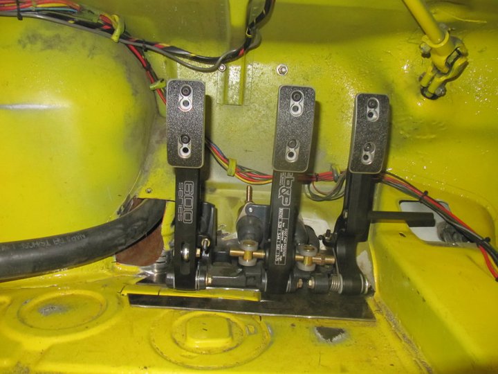
Here is how the position of the clevis's should be...tight up against the pedal to minimize the movement of the bearing: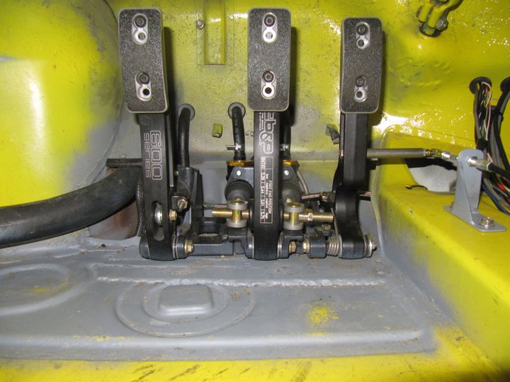
The only other observation from the event was that the fuel tank was very hot to the touch due to the close proximity to the radiator. I am limited by the SCCA rules on what type of ducting is allowed behind the radiator, so for the time being I am working on constructing an aluminum air deflectors/air gap which will be covered in heat reflective foil. This should be sufficient to keep the fuel tank temperatures at acceptable levels. Another option if it become necessary would be to run an aluminum fuel line thru a coil in the icebox for the intercooler, but we shall see.
Here is the initial mock-ups of the air deflector: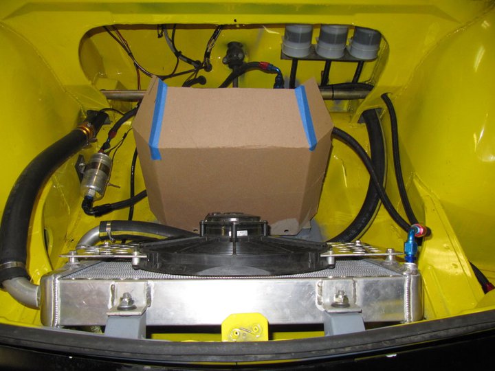
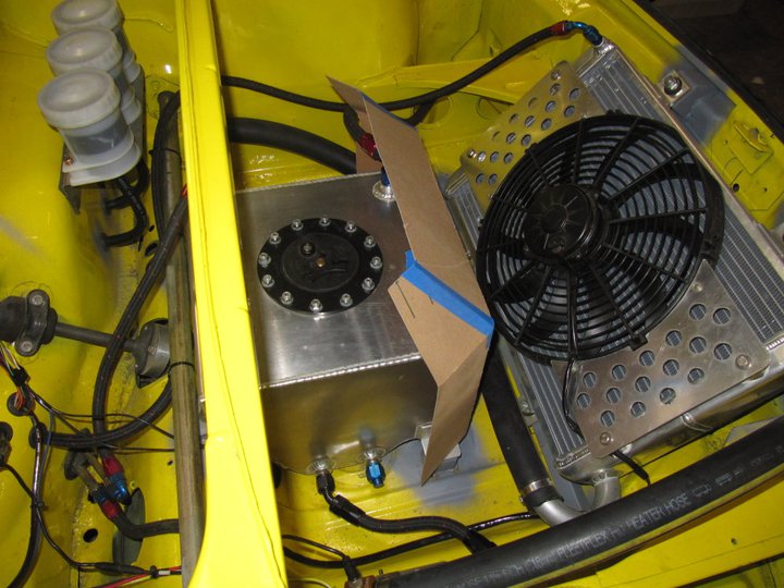
More to come after this weekends event and further dyno tuning.
-Britain
Posted by: McMark Apr 26 2011, 05:47 PM
I would bet that a simple jacket of foil lined 'bubble wrap' would keep the heat from penetrating. That bare aluminum is probably grabbing all the heat it can.
If you make the deflector, maybe use SS since it's much slower to absorb heat.
Posted by: Downunderman Apr 26 2011, 05:48 PM
Perhaps the issue with the brake balance is that the smaller of the master cylinders should be on the front and the larger on the rear.
Cheers,
Posted by: Britain Smith Apr 26 2011, 05:53 PM
Please explain this comment?
The front brakes are 911S calipers and are much larger than the rear M-calipers. Therefore, the front will need a corresponding larger amount of fluid to move to pistons. Moving the larger master cylinder to the smaller rear calipers would only cause them to lock-up even faster.
Correct?
-Britain
Posted by: McMark Apr 26 2011, 05:56 PM
From the Brakes FAQ by the brilliant Lapuwali...
Posted by: Downunderman Apr 26 2011, 07:13 PM
Yes it is. The issue is weight transfer and line pressure. The front brakes do about 70% of the work under heavy braking and must work much harder than the rears.
With the bigger cylinder on the front you are getting less pressure to the front and more to the rear. 16mm front and 18mm rear should work out about right, then use the balance bar to fine tune. The issue is not fluid volume. Someone with better knowledge of physics than me me should be able to explain it.
The thing must have been fun to drive swapping ends every time you tried to stop it.
Cheers,
Posted by: Downunderman Apr 26 2011, 07:57 PM
Apologies. I misread your post. Your proposition is incorrect.
Posted by: J P Stein Apr 26 2011, 08:50 PM
You can produce more line pressure with the smaller MC.....IF you have enough volume. The problem with the 17mm MC in the stock 914 system was the lenght of the stroke necessary to produce volume....the first 2 inches of movement had little effect on retardation. You may have had to push the pedal harder to produce the pressure with a 19mm MC but the lenght of stroke was much shorter and it comes up firm . When the wall is coming up it's nice to have a nice firm pedal to modulate......"making them worse" is total...cow flop.
Brit's difference in MC sizes is moot. He can adjust then individually to get what he wants.
Posted by: kg6dxn Apr 26 2011, 09:41 PM
I would just add a proportioning valve in the tunnel by the firewall(coupling location) Then you can bias more pressure back up front.
Posted by: charliew Apr 26 2011, 09:58 PM
Did you mention the highest coolant temperature you experienced? It seems to me that the fan needs a complete shroud to pull air through all of the radiator instead of just the center. If it's not getting too hot it must be ok as it is. I wonder how much cfm the hood vents can handle? You know the cfm of the fan. There is a formula somewhere that says the exhaust outlet needs to be a percentage larger than the intake. I think from memory it's 30% but it might be more.
Posted by: Chris Hamilton Apr 26 2011, 10:19 PM
I would just add a proportioning valve in the tunnel by the firewall(coupling location) Then you can bias more pressure back up front.
He is running dual master cylinders, this isn't possible.
Posted by: charliew Apr 26 2011, 10:44 PM
But I bet as a last resort he could put a bypass valve in the rear line to limit pressure to the rear.
Posted by: Britain Smith Apr 26 2011, 11:27 PM
Hey guys...I appreciate the insight.
Regarding the brakes, now that I have bias bar installed correctly there should be no problem balancing the brakes bias front to rear. It will take some trail and error, but it should be possible with the current set-up.
On the coolant temp, the highest that I have seen the engine after a run is just under 200degs and that is running without the radiator fan on and 60deg ambient temps. I switch on the fan while sitting on the grid and the temp drops to ~180 in about 3mins. The current set-up has proven sufficient so far, however the ambient temperature has been pretty low. I will be adding shrouding in front of the radiator when I get a chance. Regarding the hood vents, one thing to remember is that not only is air escaping thru the vents, it is coming out of the cowl vent and the hood actually lifts in the rear at speed and air escapes out of there.
On the radiator air-deflector, I like the idea of the bubble wrap foil stuff that McMark mentioned, I have some of that from makeshift tire warmers I made a while back. I will try wrapping the tank in this before going down the route of an air deflector.
-Britain
Posted by: Walter Apr 27 2011, 02:04 AM
A hot fuel tank is usually the result of an EFI engine where fuel is constantly circulated by the fuel pump and heated from the hot injectors. Do you run low-Z (low resiatance) injectors (peak and hold) or high resistance injectors (as most OEM)?
The low resistance have a very high amp flowing through them and get much hotter then the high resistance injectors.
I think insulating the tank from the radiator may not help much, but worth a try at least as its easy and cheap to do and fuel coolers are a lot more work after all.
Posted by: J P Stein Apr 27 2011, 06:31 AM
I was told that the front of the tank is hot while the back is cool. I too believe the wrap will do the trick and it is in the KISS mode. .
Posted by: DBCooper Apr 27 2011, 07:48 AM
Would never disagree with KISS solutions but would note that I get quite a lot of heat in my motorcycle gas tanks from circulating the fuel past a hot engine and back into the tank. BMW injectors and fuel lines are hanging right out in the airstream, so that might be a factor.
But you know what I most want to know is if that sucker is fun to drive. Brakes aside, of course, because it seems you've got that done. It just looks like you built a rocket, so does it feel that way in the driver's seat?
Posted by: Britain Smith Apr 27 2011, 10:10 AM
A hot fuel tank is usually the result of an EFI engine where fuel is constantly circulated by the fuel pump and heated from the hot injectors. Do you run low-Z (low resiatance) injectors (peak and hold) or high resistance injectors (as most OEM)?
The low resistance have a very high amp flowing through them and get much hotter then the high resistance injectors.
I think insulating the tank from the radiator may not help much, but worth a try at least as its easy and cheap to do and fuel coolers are a lot more work after all.
That is a good point. I do have 16mm phenolic spacers between the intake manifold and the heads which should keep a lot of heat out, but I agree some degree of heat will be coming from the circulation.
That said, the front of the fuel tank was very hot to the touch compared to the sides and back of the tank. I will wrap in an insulation material and determine if that helps with the temps.
-Britain
Posted by: Britain Smith Apr 27 2011, 10:12 AM
But you know what I most want to know is if that sucker is fun to drive. Brakes aside, of course, because it seems you've got that done. It just looks like you built a rocket, so does it feel that way in the driver's seat?
The car is a damn rocketship!!
If you watch the end of the AX video above, you can see where I come out of the 180deg turn and point the car towards the finish and hit the gas...the car accelerates like crazy!
Put it this way, the tuner at Cobb Tuning has driven everything from 600hp Subaru's to 1000hp GT-R's...he said he hasn't had this much fun in a car in 10 years.
-Britain
Posted by: Downunderman Apr 28 2011, 01:45 AM
Brit,
I suspect that you will have a great time trying to sort out the brake balance, moot as JP says it is, but it looks as though there would not be a lot of work involved in swapping the front and rear lines on the master cylinders and giving it a try. Having gone to all the trouble you have, it would be a pity to spend half a season sorting it out.
Cheers,
Posted by: J P Stein Apr 28 2011, 07:18 AM
Brit,
I suspect that you will have a great time trying to sort out the brake balance, moot as JP says it is, but it looks as though there would not be a lot of work involved in swapping the front and rear lines on the master cylinders and giving it a try. Having gone to all the trouble you have, it would be a pity to spend half a season sorting it out.
Cheers,
I didn't mean to minimize the importance of getting it just right to fit ones driving style. Straight line brakers can go with more rear bias than one who likes a to trail brake. Some AXers like the back end to step out a bit under trail braking to help the car rotate. The last time I set the rear bias was so one could trail brake (if you had to ) without upsetting the car tho I pretty much was a straight line guy. It took 2 passes to get it close enough.
Posted by: Britain Smith Apr 28 2011, 11:42 AM
As an engineer sometime the solution to a particular problem can be way more complicated than it needs to be.
Case in point -
Problem: Need more HP
Solution: Take out the Porsche engine and replace with a Subaru engine.
Anyway, for the fuel temperature issue I have decided to try out McMark's idea with a simple insulated cover made out of the bubble wrapped foil stuff used on windshield screens in the hot summer. We shall see how it works this weekend.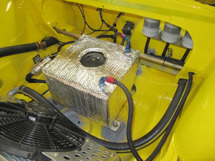
Regarding the brake bias. All the calculations that have been completed indicate that this set-up should work how it is. I just need a few passes to get it dialed in and if that doesn't work then we can evaluate other options.
-Britain
Posted by: sawtooth Apr 28 2011, 12:04 PM
Fantastic video, that looks like way too much fun. We need to get you to mount an iTouch/iphone on your dash and run http://www.greenchileproductions.com/RaceDataAX.html so we can see/feel the G's
Posted by: bfrymire Apr 28 2011, 01:25 PM
As an engineer sometime the solution to a particular problem can be way more complicated than it needs to be.
Case in point -
Problem: Need more HP
Solution: Take out the Porsche engine and replace with a Subaru engine.
Anyway, for the fuel temperature issue I have decided to try out McMark's idea with a simple insulated cover made out of the bubble wrapped foil stuff used on windshield screens in the hot summer. We shall see how it works this weekend.
Regarding the brake bias. All the calculations that have been completed indicate that this set-up should work how it is. I just need a few passes to get it dialed in and if that doesn't work then we can evaluate other options.
-Britain
Doesn't Home Depot sell AC duct wrap? I use it on my test systems that have to go through temperature cycles. It's a foil based wrap with insulating foam with adhesion. Simple to apply. Just another thought.
-- brett
Posted by: Britain Smith Apr 28 2011, 02:15 PM
Yea, that would work as well. I like this solution because I can slip the insulation cover right off the top if I need to. We shall see how it works, I have my hopes up.
-Britain
Posted by: ChrisNPDrider Apr 28 2011, 03:04 PM
The development never stops!
While the solution to more HP was indeed far from KISS, my intuition says that if you can avoid full thrashing of that engine (14 lb boost spike, Uh oh!) it will last a while and things will get (relatively more) simple.
Have you had a chance to see/feel/drive the newest Goodyear AX slicks?
I don't envy your situation with the big swings in temps and rough surfaces at home vs. the big SCCA venues!
Posted by: Britain Smith Apr 28 2011, 03:12 PM
The 14psi boost was not spike, that was sustained and just about normal for that engine. In fact, that is not even in the peak efficiency range for that turbo...the tuner wants to push around 18psi but I don't want to destroy the transmission and/or clutch. That said, I need to dial in around 7psi in cold or wet conditions and about 14psi in warm, sticky tire conditions.
I have not tried the newest Goodyear Slick. It is actually a DOT tire and not a slick.
-Britain
Posted by: J P Stein Apr 28 2011, 03:31 PM
I don't envy your situation with the big swings in temps and rough surfaces at home vs. the big SCCA venues!
The good news is that most folks in the country have a similar problem.
Some guys are lucky with big open concrete venues but, I think, the majority are not. So we hammer away on our POS venues & hope for the best.
We went to Wendover last spring. Nowhere will prepare you for the grip that place generated. It ground tires to dust. The car done good.....when we got it running on all 6. I sucked as usual.
My goal was not to finish DFL in class....OK, but I still sucked.
Posted by: BMXerror Apr 28 2011, 07:32 PM
There's something to be said for racing in less perfect conditions. Here in So Cal some of our drivers have the problem of not enough rain practice throughout the year. Then they go to Nationals, get dumped on, and then get spanked. I doubt you guys have that problem. Plus the bumps really refine your car control.
Love the video, by the way. You know it's scary fast when it looks fast on YouTube!  Keep up the good work.
Mark D.
Posted by: Randal May 1 2011, 10:03 PM
Directly from Facebook:
Britain Smith
Great day at the SCCA Autocross at PIR. Took TTOD with the Where2Race sponsored Porsche 914. Finally got the boost under control, the brake bias in check, and had some fun driving the car in anger. Can't wait to mount new tires and take the car to Packwood in two weeks.
Isn't it cool to see another 914 race car project start to get sorted out and find success.
Keep up the great work Britain, we've all enjoyed watching your project and are enjoying seeing you compete, with success, at events.
Pretty soon everyone is going to want one of those WheretoRace T-shirt, i.e. the official sponsor of the sh##-bo# 914.
Do you have yellow t's?
Posted by: Britain Smith May 1 2011, 10:49 PM
Yes, thanks Randal. Great day at the AX, car stayed together well and is getting closer to what I considered sorted out. I actually cleared my head from thinking about the car and focused on driving...even JP noticed.
Here is a video of my fastest run. I am really going to have to look into getting a better camera.
http://www.youtube.com/watch?v=Y-Et-cJPgPM
https://www.youtube.com/watch?v=Y-Et-cJPgPM
-Britain
Posted by: J P Stein May 1 2011, 11:35 PM
Indeed, on your 4th run when you came into my view I said to my self....ah, now he's workin' it.......then you looped it.....oops. Some fresh tiars well with help that but keep that trans alive.
Posted by: Britain Smith May 6 2011, 01:21 AM
Ok guys, it is late and I am going to bed...but before I do, here is a little to share.
Spent the day at COBB Tuning Surgeline finalizing the tune on my car. First off, what a great atmosphere down there and a very knowledgeable group of guys. Many thanks to head tuner Timothy Bailey and Brandon Lumpkins for their work, I know they enjoyed the ride around the parking lot.
We got the cold start enrichment ironed out so that the car is a bit easier to start on the E85 in cold to mild weather. We also tuned the new Turbosmart E-boost boost controller set-up maps at various boost set-points. This will allow me to dial in the boost level depending on weather, track conditions, course layout, and tire life. This set-up is trick and very easy to adjust.
Here are both the low boost and high boost dyno graphs.
Low Boost, 8psi: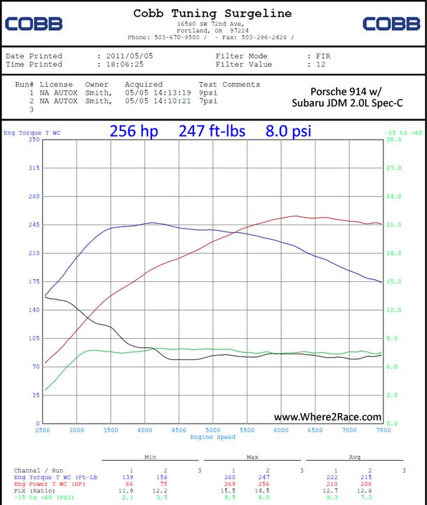
High Boost, 14psi: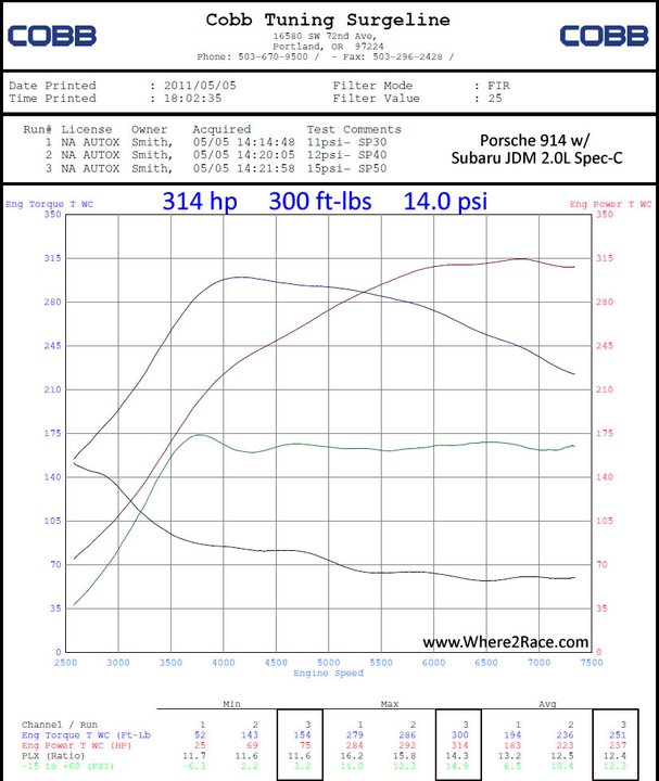
Now, the motor will easily take 18psi without issue. However, the clutch package is rated at about 400hp and the transmission/CV's are already close to the theoretical limit so I decided that I wanted to stick to this power level and avoid the exponential decay of transmission. Besides, the car is only 1800lbs and just about uncontrollable at the high boost levels.
Just as a side note, I have driven this car in competition for over 5 years and after driving it tonight thru the parking lot I got out and had a good adrenalin rush, complete with shaking hands, for a good 5mins.
Overall, the car is running great and the driving experience is beyond my expectations...it is going to be a fun year.
-Britain
Posted by: Britain Smith May 6 2011, 01:23 AM
If you were wondering, the 2-speed transmission works perfect for this application. There is not a hint of turbo lag anywhere in the powerband. Low gear is around 60mph and high gear is a measured 83mph at 7400rpm...the motor spins to 8200rpm and should be around 95mph.
-Britain
Posted by: DBCooper May 6 2011, 09:28 AM
Wow, you were right, it's a rocket! And you're now officially having more fun than I am.
Posted by: PeeGreen 914 May 6 2011, 09:58 AM
Holy crap Britain . I know the national level competition is tough but I do believe you now have a car that is able to take 1st . It's now just up to the driver
You can do it
Posted by: dlo914 May 6 2011, 10:12 AM
Yes, thanks Randal. Great day at the AX, car stayed together well and is getting closer to what I considered sorted out. I actually cleared my head from thinking about the car and focused on driving...even JP noticed.
Here is a video of my fastest run. I am really going to have to look into getting a better camera.
http://www.youtube.com/watch?v=Y-Et-cJPgPM
https://www.youtube.com/watch?v=Y-Et-cJPgPM
-Britain
A base model Gopro 170 work wonders even thought it's only a 5mpx non-hd camera with a 170 degree wide lense. Retail they go for $100. I got mine used on craigslist for $80 and spent another $30 on their suction cup mount. Here's a vid of my DD at a local small track:
Driver Side Fender mounted on my 02' IS300 manual 5spd
https://www.youtube.com/watch?v=0yHgz1GmqfU
Roof mounted on my friend's 02' S2000
https://www.youtube.com/watch?v=DlpmtWv1qKo
Posted by: Randal May 6 2011, 10:20 AM
Ok guys, it is late and I am going to bed...but before I do, here is a little to share.
Spent the day at COBB Tuning Surgeline finalizing the tune on my car. First off, what a great atmosphere down there and a very knowledgeable group of guys. Many thanks to head tuner Timothy Bailey and Brandon Lumpkins for their work, I know they enjoyed the ride around the parking lot.
We got the cold start enrichment ironed out so that the car is a bit easier to start on the E85 in cold to mild weather. We also tuned the new Turbosmart E-boost boost controller set-up maps at various boost set-points. This will allow me to dial in the boost level depending on weather, track conditions, course layout, and tire life. This set-up is trick and very easy to adjust.
Here are both the low boost and high boost dyno graphs.
Low Boost, 8psi:
High Boost, 14psi:
Now, the motor will easily take 18psi without issue. However, the clutch package is rated at about 400hp and the transmission/CV's are already close to the theoretical limit so I decided that I wanted to stick to this power level and avoid the exponential decay of transmission. Besides, the car is only 1800lbs and just about uncontrollable at the high boost levels.
Just as a side note, I have driven this car in competition for over 5 years and after driving it tonight thru the parking lot I got out and had a good adrenalin rush, complete with shaking hands, for a good 5mins.
Overall, the car is running great and the driving experience is beyond my expectations...it is going to be a fun year.
-Britain
OK, we get it, you now have to wear a g-suit coming out of corners.
Can you believe those torque figures? And it comes on so early and stays so late.
I'd say that engine is just about ideal.
Posted by: Britain Smith May 6 2011, 10:42 AM
Thanks guys...like I mentioned in my post last night...the car gives you a shot of adrenalin that takes several minutes to wear off. I can't wait to drive the thing in anger!
dlo914, thanks for the info on the GoPro. I am looking to get a SmartyCam and while I know they are much more expensive, I would like to overlay the data from my AIM dash which will make the videos much more exciting to watch.
-Britain
Posted by: ChrisNPDrider May 6 2011, 02:07 PM
Awesome
Posted by: charliew May 6 2011, 04:12 PM
Just my be prepared idea but why not get a 18 psi boost tune? You know you will get aquainted really well with the tune you have and you WILL be able to use more at some point. The higher boost will mean lower rpms overall I would think although it might get a little twitchy. I always thought a new fast motorcycle was fast and it made my knees shake but only for a while.
Posted by: Britain Smith May 6 2011, 04:18 PM
The tune is good up to 18psi and there is no reason on the engine side not to go there. However, the last thing I want to do is burn up the clutch or blow the transmission on the dyno. Believe me, the car is a handful at 14psi and until I feel I need more power, that will be the limit. There is something to be said about going to an event and not have to wrench on the car or scramble to fix something.
-Britain
Posted by: J P Stein May 6 2011, 09:05 PM
IMO Brit needs more rear tire to handle 14 PSI, much less 18 PSI.....having said that, I'm sure it will come.
The car is now nearly as quick as before the swap with Brit driving. It'll be quicker with new 10s but really needs new 12s. The 12s may well induce driveline breakage. Now is not the time for that. Now is the time for learning to deal with the beastie with 50 more hp/ftlbs and concentrating on the driving rather than worrying about the car. It appears to me that the driving style of the turbo vs the NA is different.
Posted by: grantsfo May 26 2011, 02:29 PM
It appears to me that the driving style of the turbo vs the NA is different.
Yep espeically low displacement turbo motors like this one. You can see the cliff where power falls off from the dyno. Need to be on early and learn how to left foot brake like a mad man.
AWD cars are a little easier as they allow you to get on turbo early. 2wd is a little tougher but Brit will figure it out.
I liked the torque from my 2.3 DI turbo MS6. It pulled like a tractor from 2400 RPM. Of course I had 2000 more lbs of car to haul than Brit!
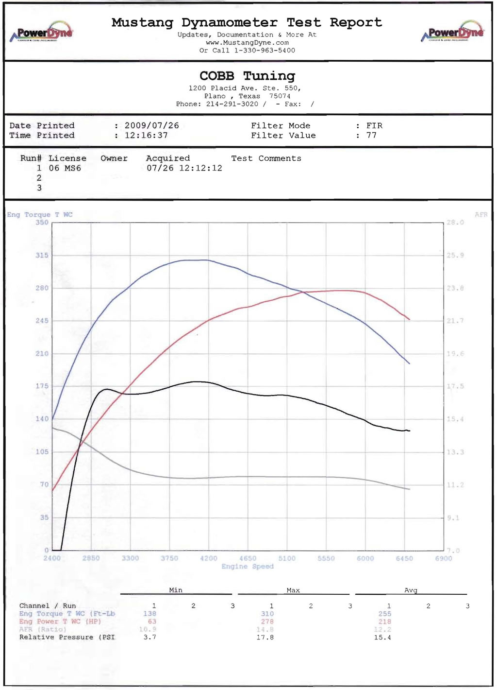
Posted by: Britain Smith Jun 2 2011, 01:16 PM
Sorry for the lack of updates guys, been really busy with work and spending time with the family. Got some time this last week to get some items in order.
At the last event up in Packwood, I dealt with fuel starvation and fuel temperature issues. Basically, about the 4th or 5th run in the car (with 2 drivers), I would get fuel starvation issues going thru sweepers and long corners. I would bring the car back into the Pits and top off the fuel tank. While the fuel level was not really low, I would fill it up anyway. After doing this, I observed fuel coming out of the vent tube on the tank. There is a check valve in the tank, however it was fluttering up and down and letting fuel thru. I determined that this was a result of high fuel temperature (E85) that was pressurizing the tank once the cap was installed. I was unable to continue running that afternoon and have made some changes to the fuel system that I will test this coming weekend.
In this older image, you can see the position of the fuel pump. I had it mounted about 3" higher than the bottom of the tank and farther forward...meaning the fuel had to go uphill and forward while the car was accelerating. I guess I was under the assumption that these pump had more suction that they really do.
In either case, I have now relocated the pump inside the passenger compartment and level with the bottom of the fuel tank. The fuel line now snakes by the steering rack and thru the front bulkhead. 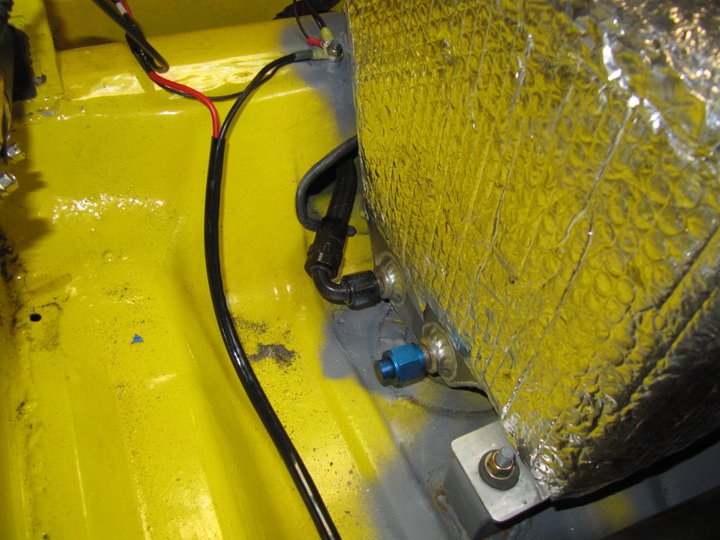
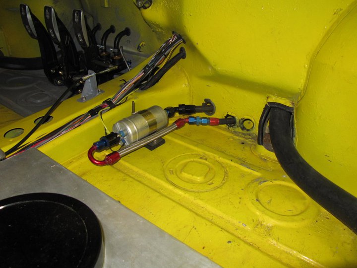
This configuration will also have the added benefit of keeping the fuel pump cooler and it is not exposed to the heat coming off the radiator. Further tests and observations will be completed at the upcoming events.
I also tried my hand at some sheetmetal work to complete the radiator shroud between the front bumper and the radiator itself. It is really nice when you have access to a shear, brake, and one of those air powered nibblers. It is really hard to take a good picture of this, but it is all sealed up and you get the general idea.
And finally, got the car corner balanced and aligned. I was surprised to see some of my alignment specs out from where I expected them to be, but I got the car where I want them. The corner weights came out perfect and I have a solid 45/55% weight distribution.
-Britain
Posted by: Britain Smith Jun 14 2011, 05:42 PM
Despite the work I had done to the fuel system, I continued to have fuel starvation issues. I believe that the combination of fuel slosh and a high flow fuel pump combined to emptying out the sump in the fuel tank quicker than the fuel could return....therefore causing air to be sucked into the system. Therefore, I set about to redesign the fuel system with a much better set-up.
The first thing I did was mock up the approximate size of the JAX Pro Stock fuel tank (8x8x15") in cardboard to determine if I could get it to fit in the stock fuel tank location. 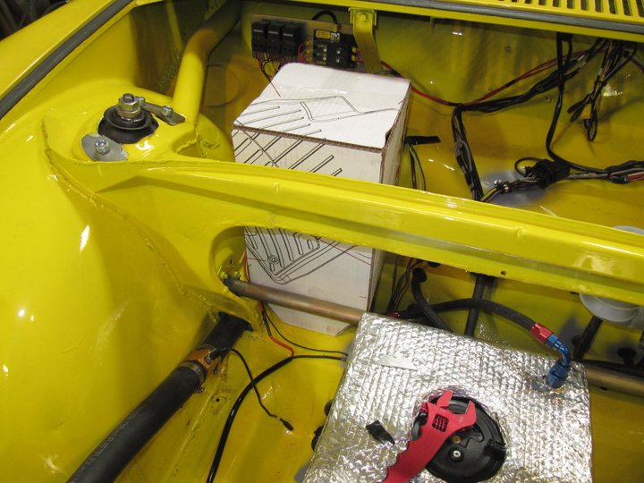
When I called JAZ to discuss the tank, I was able to order it in the exactly specifications that I needed. I went with a high flow AN-10 fitting at the bottom to feed the fuel pump, an AN-6 return line fitting, and an AN-8 vent line fitting.
This is the beginning of the new fuel tank install. I got the tank in "natural" finish so I can monitor the fuel level without having to look down inside. 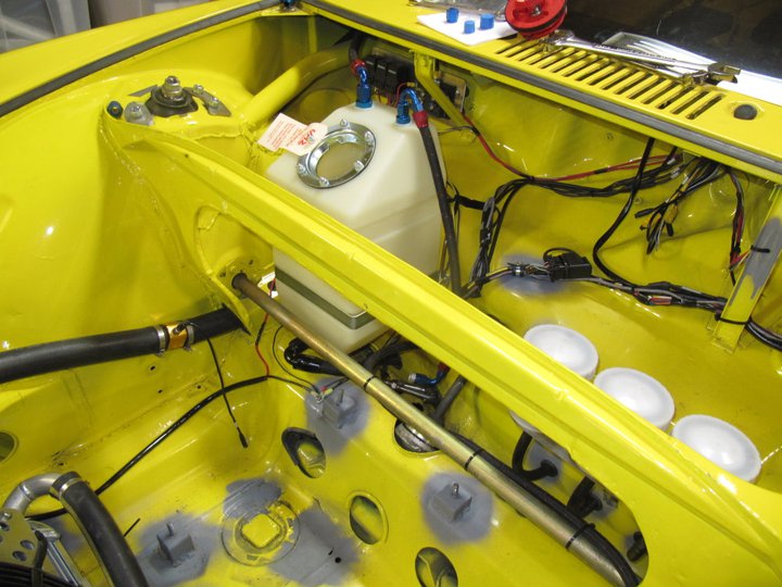
Here is the tank completely installed. Worked perfectly all the way down to the level of the fuel in this picture. The engine felt so much more responsive and never bogged down...success!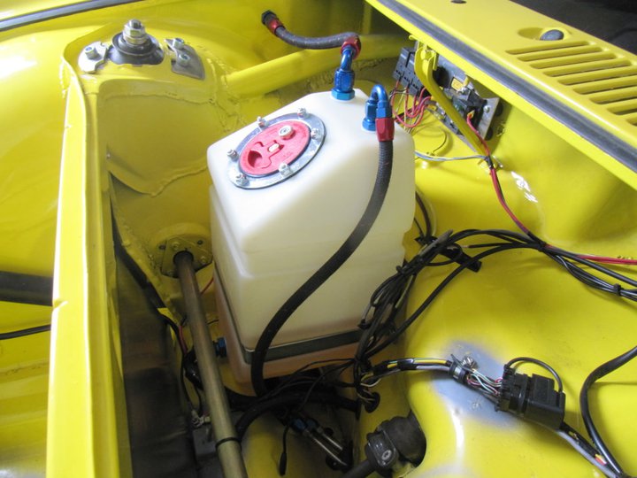
Placing the tank in the stock location not only allowed an elevative position in relation to the fuel pump, it also allow me to fab up a new firewall to separate the radiator heat from the fuel system.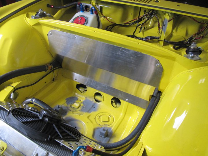
After running the car through 16 runs at the last AX event, the firewall was VERY hot to the touch and the fuel tank was only moderately warm. I am very happy with the results and now I can return my focus on driving.
-Britain
Posted by: DBCooper Jun 14 2011, 05:52 PM
-Britain
With all he radical changes you made to that car if it only took you that long to sort things out it means you've done an exceptional job. Congrats. Be proud, that's VERY well done and we're all envious.
Posted by: Britain Smith Jun 14 2011, 05:58 PM
Many Thanks.
It was actually quite frustrating that of all the changes made to the car, I was fighting the fuel tank. Car is ready to go for the WCR in Medford in two weeks. I also bought a new truck to tow my trailer more efficiently on long hauls...can't wait to make the trip.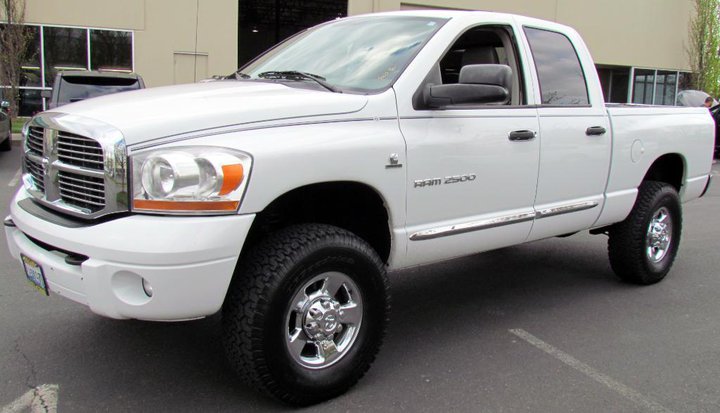
-Britain
Posted by: ChrisNPDrider Jun 14 2011, 08:39 PM
After running the car through 16 runs at the last AX event, the firewall was VERY hot to the touch and the fuel tank was only moderately warm. I am very happy with the results and now I can return my focus on driving.
-Britain
How did it go? Did you win?
Posted by: Britain Smith Jun 16 2011, 03:15 PM
Here is a video from the last event taken with a friend's Go-Pro. I need to pull the video from my camera to compare. I will be the first to admit that my driving is a little behind after spending all my time sorting the car, but now that the car is working well I can focus on having fun again.
The sound of the engine is awesome, gotta love the Suby spinning to 8200rpm. Enjoy...
http://www.youtube.com/watch?v=u8DUqVoMGMk&feature=youtu.be&hd=1
-Britain
Posted by: PeeGreen 914 Jun 16 2011, 03:23 PM
Looks and sounds great
Awesome venue 
Posted by: Britain Smith Jun 16 2011, 03:26 PM
Yea...venue sucks. The car is actually a bit to stiff now for that crappy place. I can't wait to stretch its legs down in Medford and then Packwood on the same weekend. Let the fun begin!
-Britain
Posted by: Britain Smith Jun 16 2011, 08:52 PM
Here is in-car video from the same run. Little different perspective...just as much!
http://www.youtube.com/watch?v=iNdMq03Zwg8&feature=youtu.be
-Britain
Posted by: jzdu Jun 16 2011, 09:55 PM
Looking forward to seeing you run down here
Posted by: Britain Smith Jul 25 2011, 11:25 PM
Well, it has been a while since I have updated this thread.
Two weekends ago was the Packwood National Tour, me and my co-driver took 1st and 2nd in a field of 14 drivers. While it was nice to finish out on top, we struggled in the car all weekend due to lack of rear grip and changing weather conditions.
Here are the video's of my fastest runs.
Saturday:
http://www.youtube.com/watch?v=L4yHNRq6cbI
Sunday:
http://www.youtube.com/watch?v=u0lQXPahUvw
With the new engine set-up, as more power is dialed in with the boost controller all the shortcoming in the suspension start being amplified. To date I have already corded two sets of rear tires and I have pretty much destroyed a third set after running the Tour and the ProSolo event this past weekend.
To dial out the understeer on the car, I went about stiffening up the rear suspension from 275lb to 325lb rear springs. With that change I had difficulty putting the power down and the rear of the car became very tail happy both on and off the throttle. Adjustments to the front sway-bar did very little to help.
During the ProSolo this past weekend I decided to revert back to the 275lb rear springs and that made a world of difference in getting the power down and settling the rear end. In fact, it was so dramatic that I red-lighted three runs in a row despite leaving the tree at the same time as I did on previous runs. I won't say that it cured the oversteer, but it helped.
Here is a video of the ProSolo fun:
http://www.youtube.com/watch?v=cp4KiVPQSr8
-Britain
Posted by: Britain Smith Jul 25 2011, 11:33 PM
Now it is preparation time for Nationals. Due to the struggles that I have had with the current tire set-up...I have seen the light and now realize that it is time to try something different and go big!
Therefore, with the 3 free tires that I won thru contingency with Hoosier, I am going to switch from Bias Ply to Radials. I should be able to get at least 2degs of negative camber dial in, hopefully a bit more. I have also decided to increase the mechanical grip in the rear from 10" to 12" wide tires. This will require me to do a little "modification" to the rear fenders...but as they say, Go Big or Go Home!
I should get the tires in the next week and I will post pictures when I receive them.
-Britain
Posted by: Britain Smith Jul 25 2011, 11:50 PM
So, this brings me to the topic of my next project. I want to ditch the '70 era suspension design and move into the 21st century.
Here is my problem.
Front Suspension: Current set-up is McPherson strut design which gives ~2.5" of scrub with 8" wide wheels. You are also limited in available, acceptable, shock designs.
Rear Suspension: Semi-Trailing arm which is making it difficult to get the power on the ground.
My plan is to move to a double wishbone, multi-link suspension set-up both front and rear. With that in mind, I have made some measurements and decided to basically transplant a Lotus Elise/Extige suspension onto my chassis. I will optimize the positioning of the attachment point for my ride height and basically copy the good hard work from Lotus for the rest of the placement. The best part is that the available shock choices are infinite...I have seen sets of Öhlins for around $1000 to $1500.
Here is a good view of both the front and rear set-ups.
Front: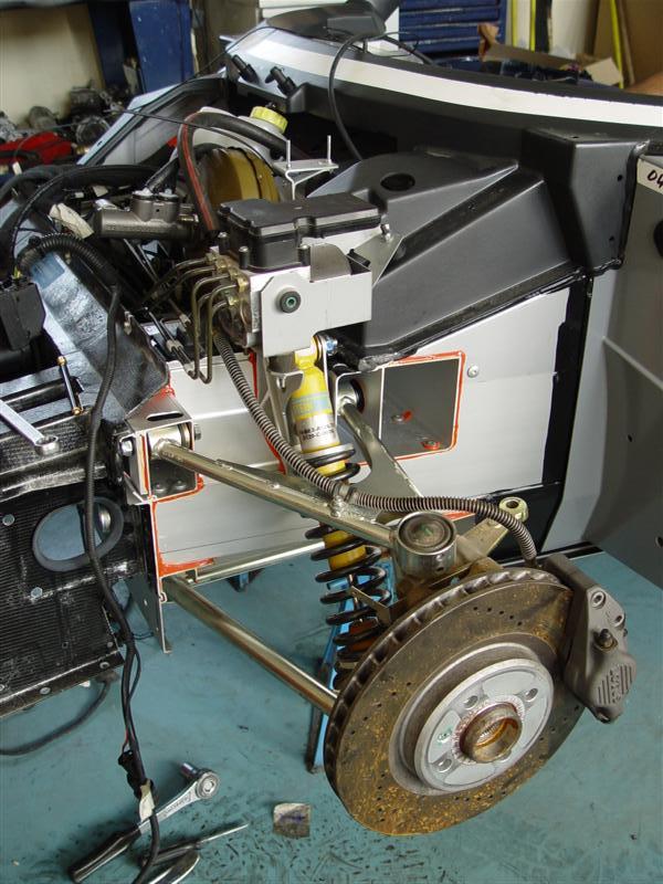
Rear: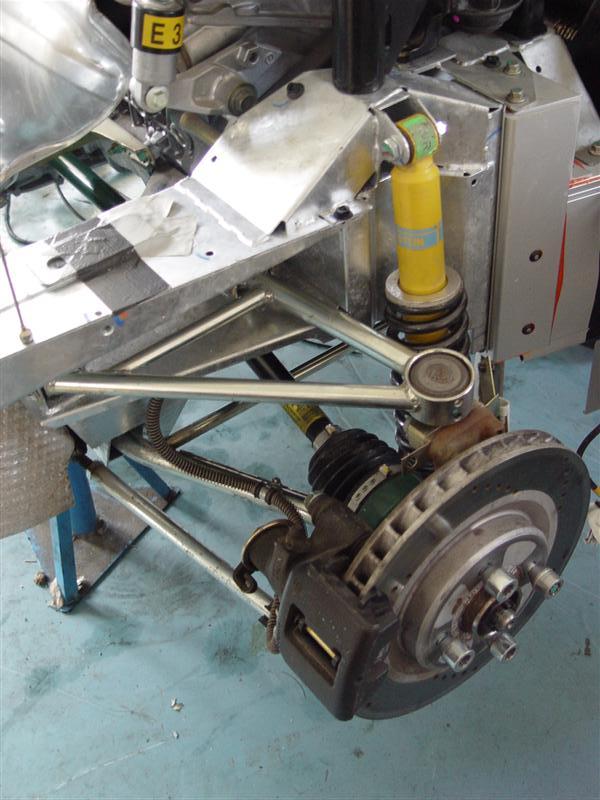
I am currently working on locating the necessary parts, so the ball is already rolling. I will post pictures as I go. If you know anyone that might have Lotus suspension parts, please let me know.
-Britain
Posted by: cantgo2fast Jul 26 2011, 01:33 AM
Wow this is a fantastic build just read the whole thing tonight. I hope to be going down this road by next year sometime. I will definitely be hitting you up for those wiring diagrams. I just cant justify running an ej207 and not utilizing the avcs.
Not to throw another project on you but have you ever thought about doing an electric shift system. I realize its only two gears but it would allow you to keep your hands on the wheel.
Secondly, what is with that rear wing? A class restriction? it looks like its just a wall. If you want to know where to get a really nice carbon dual element wing with real engineering and CFD numbers behind it let me know.
Great build either way and looks like a blast. Im hoping to come out to nationals this year with our race car (Colorado state FSAE). We retrofitted an aero package and gained about 30 hp  so hopefully we can be more competitive.
Posted by: Britain Smith Jul 26 2011, 10:19 AM
Yea, I would love to get more information on a rear wing from you. The spoiler is left over from the days that I ran E-mod.
I look forward to meeting you at Nationals.
-Britain
Posted by: andys Jul 26 2011, 01:20 PM
Britain,
Have you perhaps considered grafting in a suspension from a Boxster. This reasoning is based on a couple of factors: 1.) parts are plentiful and sure to be lower cost than the Lotus parts, 2.) lots of mature race development with spec Boxster racing; they are a very good handling car. I'm a roadrace guy, so I know nothing really about AutoX, but there should be enough similarities. Just a thought.
Andy1
Posted by: ChrisNPDrider Jul 26 2011, 01:54 PM
photos!!
Great job so far, and good luck getting it sorted for the BIG SHOW
Posted by: cantgo2fast Jul 26 2011, 02:02 PM
Heres the write up on the wing development. It's definitely tailored to road racing but it has real engineering behind it and is sure to work. Good read too, not too complex.
http://www.amb-aero.com/files/APR004_public.pdf
It will undoubtedly be a while before production but it might be ready for next season.
Posted by: Britain Smith Jul 26 2011, 02:37 PM
Britain,
Have you perhaps considered grafting in a suspension from a Boxster. This reasoning is based on a couple of factors: 1.) parts are plentiful and sure to be lower cost than the Lotus parts, 2.) lots of mature race development with spec Boxster racing; they are a very good handling car. I'm a roadrace guy, so I know nothing really about AutoX, but there should be enough similarities. Just a thought.
Andy1
Hey Andy. The Boxster suspension was evaluated, however it is built for a heavier car and still uses strut design which is what I want to get away from. I think you would be surprised how cheap the Lotus parts cost.
-Britain
Posted by: Britain Smith Jul 26 2011, 02:40 PM
Heres the write up on the wing development. It's definitely tailored to road racing but it has real engineering behind it and is sure to work. Good read too, not too complex.
http://www.amb-aero.com/files/APR004_public.pdf
It will undoubtedly be a while before production but it might be ready for next season.
Very interesting article...we will be in touch. I have address the power, now I am working on suspension, and finally I will optimize aero.
-Britain
Posted by: Britain Smith Jul 28 2011, 12:23 AM
Hey, I totally forgot to show you guys the new Where2Race Motorsports T-shirt. Check it out, these turned out awesome.
Get your hands on one today, $18 shipped to your door. I only have a limited supply of Large and X-Large at the moment. Drop me a message at info@where2race.com for details.
-Britain
Posted by: Britain Smith Aug 20 2011, 12:32 AM
I want to give you guys a quick update as I prepare for the SCCA Nationals in Lincoln.
At the Packwood NT, we continued to struggle with lack of rear grip. Although I have tried several adjustments, springs, sway bars, etc., I just can't get the balance like I want it. If I compensate for the rear grip, then the car suffers from understeer. If I adjust that out, I have trouble keeping the rear end under control. Either way, the current set-up was just not working.
Therefore, short of completely changing the suspension to something from the 21st century (that is coming soon), I decided to take my tire contingency winnings and get a set of Hoosier Radials. For reference, my old set-up was 23.0x9.5x15 cantilever fronts and 22.0x10.0x16 rears, both bias ply in R35B compound. My new set-up are 23.0x10.0x15 R25B fronts and 23.5x12x16 R75 rears. The thought here is that the softer fronts will allow them to heat up faster and provide good front grip and the rears will last longer and provide more mechanical grip from the wider width.
In order to fit the larger wheel tires properly, I was forced to rebuild the rear wheels. I first disassembled the 3-piece wheels.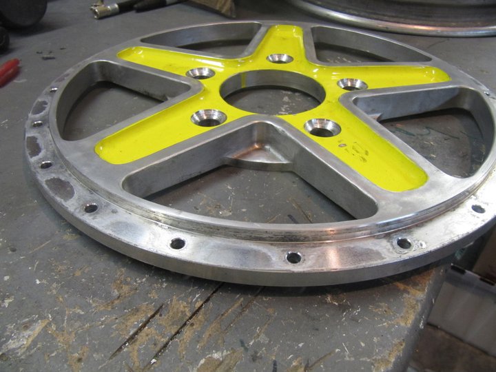
Unfortunately the older wheel barrels were not BBS and where actually welded together at the seam. I therefore had to source 5" inner halves and 7" outer halves to make this work.
Here are the wheels assembled. Gotta love the "dish"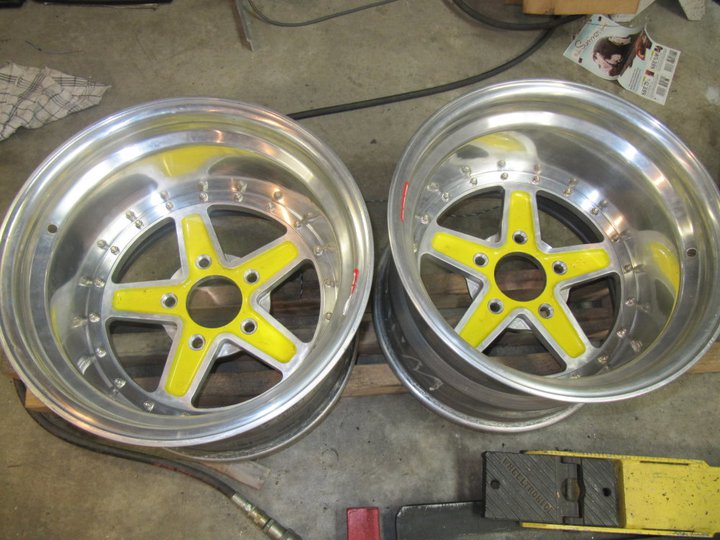
Now I was able to mount them to the car and see exactly how far they were going to extend past the fenders.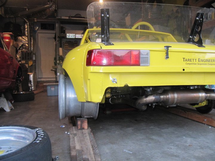
For the fender profile, I decided to follow the profile of the tire instead of maintaining the fender profile. Here is my quick and dirty wheel profiling tool.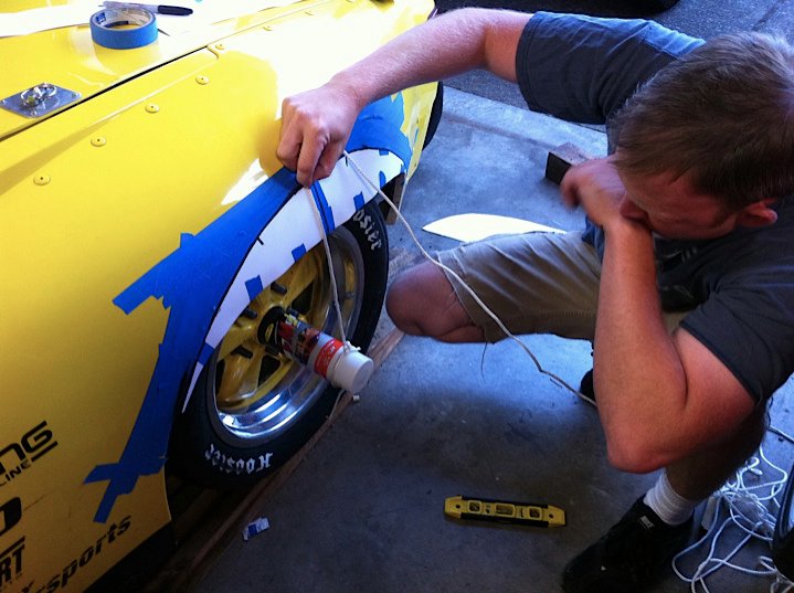
The first cut was actually the hardest part. This isn't the best picture of the procedure that I used because I actually created a pattern out of hardboard as a reference while I cut.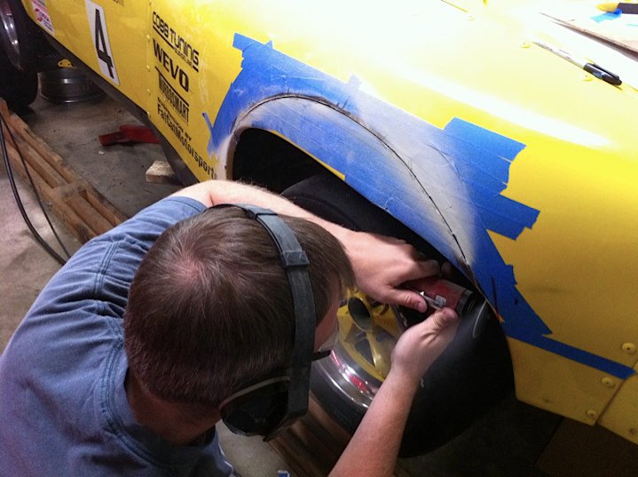
Here is the approximate location of the rear tire, there is about 2" or clearance all around.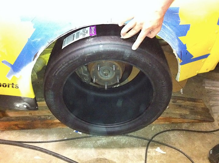
The 12" tires extend out about 1.5", hence the reason to cut the rear fenders.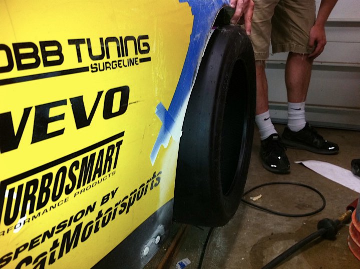
Posted by: Britain Smith Aug 20 2011, 12:40 AM
The next day I was able to finally get the new tires mounted. They look awesome.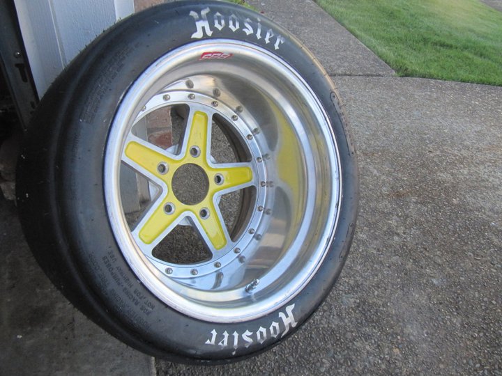
With them mounted on the car, you can compare the size of the 12" to the older 10" wheel.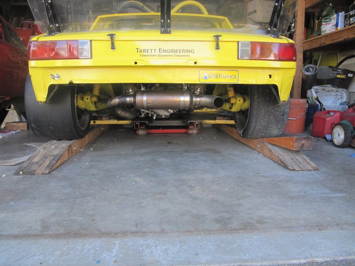
Check out the "dish"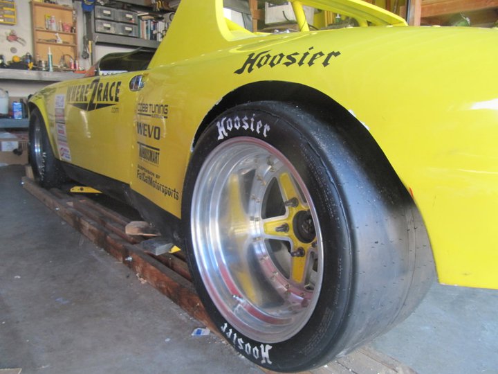
Here is a great picture of my daughter that JP had posted in the paddock.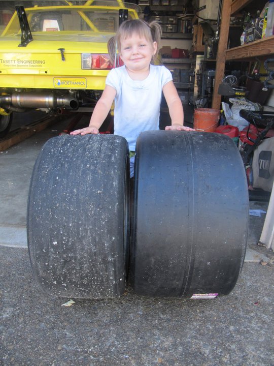
And mounted on the car...so sexy!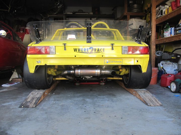
Final shot with the car on the ground and all the new sponsor stickers added.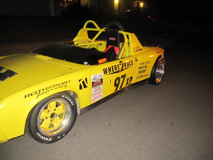
I then took the car to get the alignment changed from a Bias Ply set-up (i.e. minimal camber) to a Radial set-up (i.e. maximum camber). We were able to get about 2.6degrees of camber all around and the toes just about where I wanted it. We have now ran into the issue that all the suspension adjustments are maxed out and I can't adjust them any more if I wanted to. The rear has no shims left and the front is using a set of Wevo CamberKing plates that have the shock mount offset inboard. If I want further adjustment then I will have to go a different route with the suspension.
I will get some more pictures of the car in action this weekend in Packwood. This will be my only test & tune opportunity before I leave for Lincoln next Sat.
-Britain
Posted by: JRust Aug 20 2011, 10:21 AM
Holy crapola that is alot of wheel & tire back there. Your a skinny dude but you sure have a fat ass  . Seriously though those really are wide. Hopefully it will help with your rear end issues. At least until the suspension fixes for next year. I look forward to the packwood pics & to hear how it feels with this new setup
Posted by: DBCooper Aug 20 2011, 12:49 PM
She's a cutie. Daddy's girl too, I'd suspect.
Why do you need all that power, anyway? Couldn't you get grip back by just dialing back on the boost?
Slippery slope. And really cool stuff.
Posted by: J P Stein Aug 20 2011, 03:30 PM
A new test for the 901 trans. It's gotta be gettin' close to its point of maximum abuse.
Posted by: jmill Aug 20 2011, 06:20 PM
A new test for the 901 trans. It's gotta be gettin' close to its point of maximum abuse.
I was thinking the same thing. That's a whole lot of tire back there. Keeping my fingers crossed your light enough for the 901 to handle it.
Posted by: BMXerror Aug 21 2011, 09:13 AM
Looking awesome as usual, Britain! Can't wait to see it in person next week. Go get 'em!
Mark D.
P.S. Are you running the Pro finale?
Posted by: Britain Smith Aug 21 2011, 11:07 PM
Thanks guys...new set-up feels great. Just gotta drive it harder with the extra grip.
Not attending the ProSolo Finale.
-Britain
Posted by: Rod Aug 27 2011, 10:40 AM
Christ that looks mean!!
Great work Britain, I can't image how hard that first cut was!!
Posted by: get off my lawn Aug 29 2011, 12:57 PM
YPAF, even if it's JP's ole sheetbox ;-)
Posted by: BKLA Aug 29 2011, 01:05 PM
He's in Lincoln NE this week for Nationals...
Wish him Luck!!!
Posted by: Britain Smith Sep 7 2011, 12:06 PM
Well...you win some and you lose some.
The experience at the 2011 SCCA Solo Nationals was an interesting one. First off, the drive was very long...we made it 18hrs to Cheyenne, WY the first day and crashed at my brothers place and then another 6.5hrs the second day. Next time I might give myself a bit more time to make the drive to make it less painful.
Anyway, we when arrive we were overwhelmed at the size of the place. The paddock area alone was 0.7miles long. There were great looking cars and towing rigs everywhere. I was pitted next to Leeds Gullicks 914 and Jacksons 914 was a few rows over...kinda cool.
So we started off on Monday running the practice course. Car is running great despite the higher altitude (~3500ft), thank god for modern day fuel injection and a turbocharger. However, right away we starting picking up more and more understeer at the tires heated up. We went back to increase the rear spring rate and try it again and are still struggling with an on-throttle push that made the car very undrivable. That evening we made further changes like moving all the ballast plus some (50lbs) to the front trunk of the car and putting the front sway bar on full soft. All of this made small incremental improvements but made for a difficult weekend.
My conclusion on what happen is that once the rear tires got some heat in them they were very grippy on the concrete in the hot conditions and were overwhelming the front tires. We were unable to experience these types of conditions locally in Packwood due to the lower grip surface.
Here is a video of my runs on both the West course and the East course. You can clearly see how bad I was struggling with the car which is why my times were so off the pace.
http://www.youtube.com/watch?v=SA7kQjCvp2s
Posted by: r_towle Sep 7 2011, 12:11 PM
Wow, I got tired just watching that run...its one long slalom.
Maybe you need more tire up front, or less in the rear.
Rich
Posted by: Britain Smith Sep 7 2011, 12:13 PM
Now...we must move on and further the development of the car. One thing that was pretty obvious at Nationals is that the 40+ year old Porsche suspension has some serious shortcomings when compared to modern cars. Therefore, I have decided to go down the path of converting the chassis to a double a-arm set-up and I am starting with Lotus components.
Just before I left for Nationals, I was able to locate a wrecked Lotus in Utah and it worked out perfectly to swing by on the way back from Lincoln.
I was able to get the front and rear suspension parts from. I was also able to source the both subframes. The rear unbolts from the car and the front required a little sawzall action.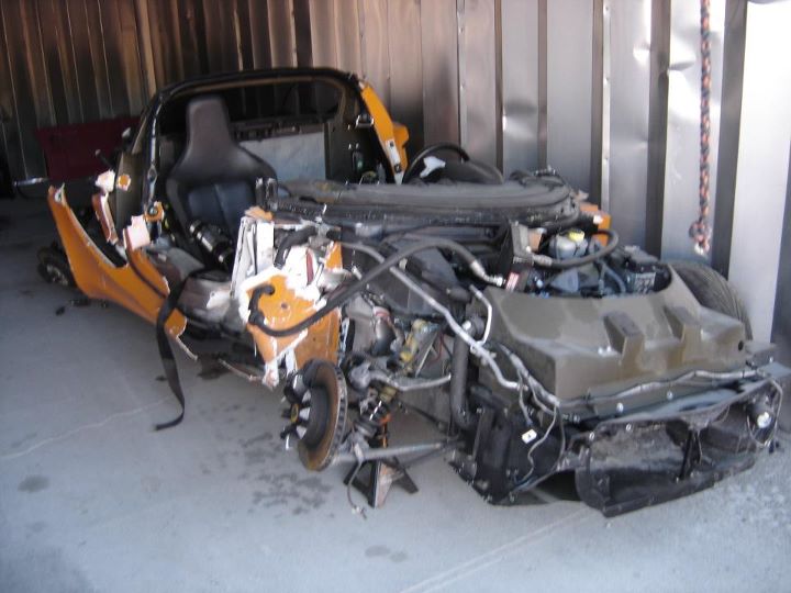
Here are all the components I sourced from the wrecked Lotus. The passenger front upper control arm and the passenger rear lower control arms are bent and new ones will need to be sourced.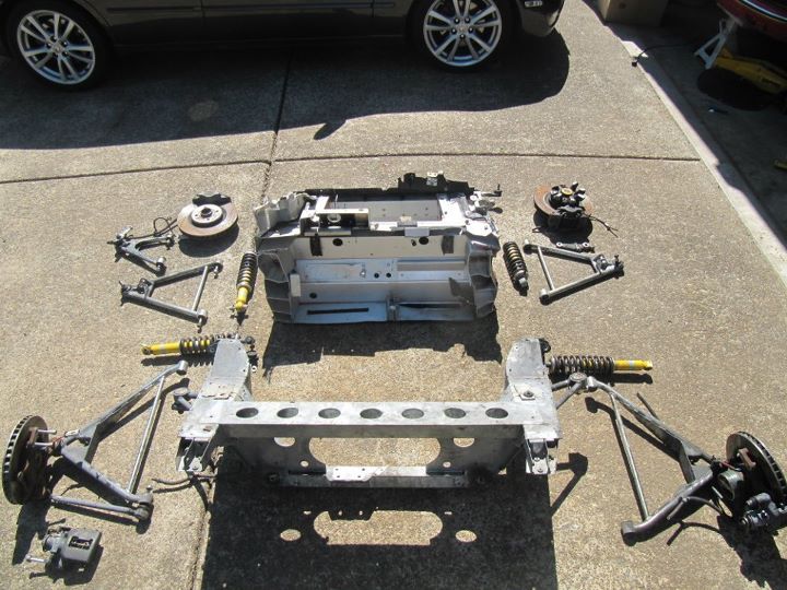
Passenger rear components. This arm is actually bent and will be replaced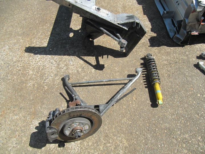
Front passenger components. Everything check out here...still need to get the proper 14mm star bit to remove the broken wheel center from the hub. Check out the broken shock.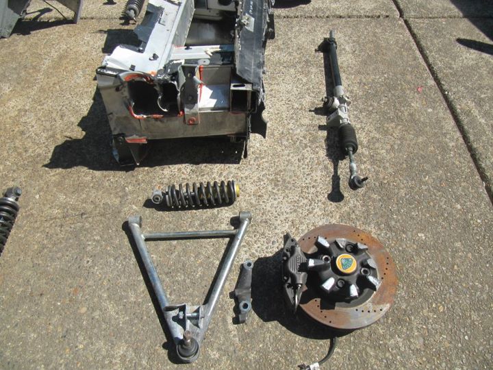
Front driver side components. Everything here checked out fine.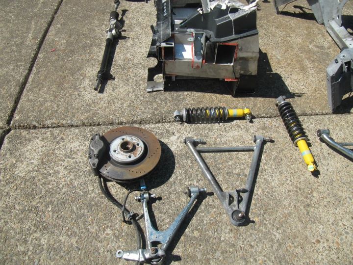
Driver side rear...all good here as well.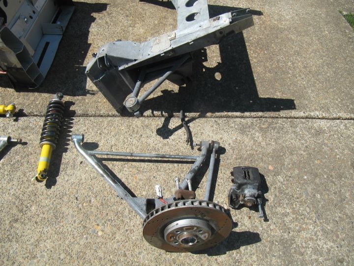
This is the front subframe assembly after about 3 hours of trimming with the combination plasma cutter, sawzall, cut-off wheel. That is the scrap pile in the back I must say that Lotus engineers did a great job in packaging on these cars. All the pick-up points appears to be intact and should be good for mock-up.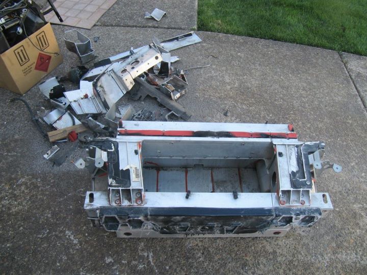
All excess material trimmed around each suspension pick-up point in order to aid in bolting and unbolting the components during mock-up.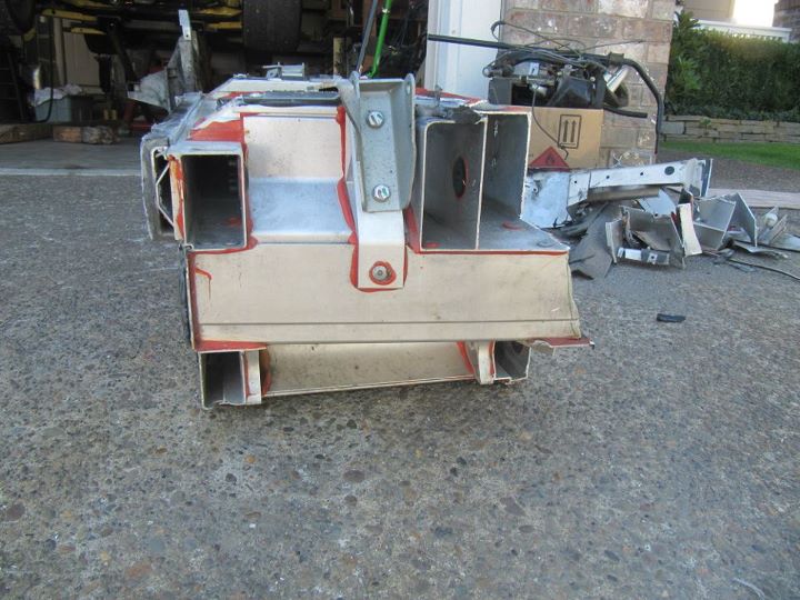
All the components cleaned up and laid out. Having a little issue removing the rusted bolts holding the rotors on the hubs, I will tackle that again later.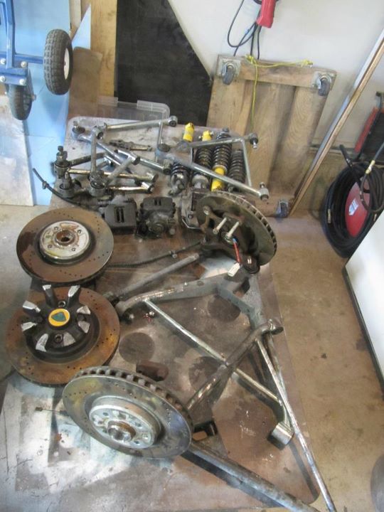
This project will start off a little slower than my engine conversion because I have lot of measuring and mocking up to do. In addition, the car will attend a few more local events before getting torn apart for the winter.
Stay tuned,
-Britain
Posted by: Britain Smith Sep 7 2011, 12:16 PM
Wow, I got tired just watching that run...its one long slalom.
Maybe you need more tire up front, or less in the rear.
Rich
More tire in front is the proper response
The 10" rear tires were not enough to hold down the power of the engine...which is why I went to wider rear tires.
The front suspension suffers from too much scrub if I go wider with the current set-up...hence the need for double a-arm set-up.
-Britain
Posted by: BKLA Sep 7 2011, 12:32 PM

More, better, faster.... Oh Yea!
Posted by: maf914 Sep 7 2011, 02:09 PM
Do you intend to use the front bulkhead assembly from the Lotus? If so, how do you intend to attach it to the 914 tub?
Wild project! Like JP has said in the past, that is one slippery slope!
Good luck with this and thanks for sharing. This is a great thread.
Posted by: Britain Smith Sep 7 2011, 02:21 PM
Do you intend to use the front bulkhead assembly from the Lotus? If so, how do you intend to attach it to the 914 tub?
Wild project! Like JP has said in the past, that is one slippery slope!
Good luck with this and thanks for sharing. This is a great thread.
Nope, that bulkhead assembly is just for mock-up purposes. I will fabricate my own to fit the chassis.
-Britain
Posted by: Andyrew Sep 7 2011, 03:18 PM
Awesome! Progress is good
Posted by: grantsfo Sep 12 2011, 03:14 PM
Best thing you could do for a 914 is put a real suspension from lotus on the thing!
Can you legally put rear suspension on the 914 in XP?
I think the Boxster had a "slight" handling edge over your car on the West course.
2100 lb Boxster getting done on West course with 200 HP.
http://www.youtube.com/watch?v=6bSamEj-9CA
Well maybe East course too.
http://www.youtube.com/watch?v=DJ0r1g2HgOM
FYI we were running 315 rears and 285 fronts. A6's rule!
Posted by: Britain Smith Sep 12 2011, 03:24 PM
Slight handling edge is an understatement...I had horrible understeer that I couldn't dial out. In addition, when I got back to Portland I determined that I didn't have full throttle either. Even with my 40year old suspension I shouldn't have been that far back behind the Boxster.
-Britain
Posted by: grantsfo Sep 12 2011, 09:48 PM
Slight handling edge is an understatement...I had horrible understeer that I couldn't dial out. In addition, when I got back to Portland I determined that I didn't have full throttle either. Even with my 40year old suspension I shouldn't have been that far back behind the Boxster.
-Britain
Lol! You seemed to have "throttle issues" at San Diego when the boxster cleared you by couple seconds too. A lot more development has gone into that Boxster since you ran against it at National Tour. We got 10 more hp by fixing headers and by intalling more free flow exhuast, sorted suspension with full mono balls and better GT3 rear arms and while it was only 60 lbs lighter than when you saw it in San Diego it has far more weight up front. Over 100 lb change in front weight bias. I spent many weekends after getting it back from Brad pulling more weight off back so we could put radiators back up front. Based on few straights in video your car was getting to speed fine. As you know West course wasnt about power but holding speed. Your corner entry speeds were much slower then both me and my co-driver. We were carrying more consistent speed in slaloms as well. And the gearing with 18s was Eriks plan that paid off big.
Look at Tobys Times against Zust in 2010 NT in his FP BMW when he ran XP. He cleared your FP car by even more than his co driver and Evan in the Boxster.
http://www.scca.com/documents/resultfiles/results16.pdf
Zust only beat him by second and a half. Boxster beat Toby the new FP national champion on the West course this year. Don't underestimate the car it is very quick. I can assure you Boxster put appropriate distance on you. You will see once you get real suspension under you. But then we were prepared and well rested for Nationals with a car that we froze development on months before nationals. We had weekly calls etc to get it set. Had all spares we needed too and then Chose the right driver to get job done. Fast guy with mid engine driving experience. We didn't show up to Nationals to sort the Boxster.
Once you get real suspension under the "914" you should be able to keep up with the Boxster. You are on the right track but have to say you are doing exactly what I said would have to be done to make a 914 nationally competitive. I didn't have time or resources to spend several years developing a full on XP 914 build like this one. With suspension mods your likely 2 years out from being ready now. Boxster was quick and simple path to a national level car in FP. Very capable car right out of the box. Erik who drives a national level SSM car says Boxster out handles his Mazda. And Boxster has abs. You have abs plans too? We did lots of work on brake balance this year. Car was amazing under braking. Especially that fast sweeper. I was under driving the car.
Good luck with the lotus suspension. This should be very interesting!
Posted by: Britain Smith Sep 12 2011, 10:26 PM
What do you want me to say Grant...I have explain the amount of issues that I had so comparing times is not relevant. I rolled the dice and made a change before Nationals and I ended up paying for it. You are correct, I had slow corner entry speed...the car pushed so badly that it was the only way to get it to turn. However, you are not correct about the throttle issue. I didn't know exactly what was wrong so I had turned the boost up almost all the way to get that kind of speed. After fixing the throttle for this past weekend's event I had those kinds of speeds at the lowest boost setting possible, the difference was night and day. I can now light up the rear tires easily, something that I couldn't do at Nationals. I will continue the development of the car and try again next year.
-Britain
Posted by: Britain Smith Oct 22 2011, 01:51 AM
Ok...this winters project has official begun. It was very difficult to make the first cut, but after four 12-15hr days we finally have a Lotus double a-arm front suspension mounted in a 914. In the spirit of the SCCA X-Prepared rules, I wanted to integrate the assembly into the unibody the best that we could without completely tubing the front of the car.
I began by mocking up the Lotus suspension assembly in the Lotus front sub-frame. 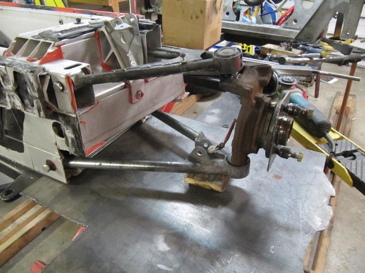
Then I secured the hub and built a quick jig to locate the chassis pick-up points to translate to the 914 chassis.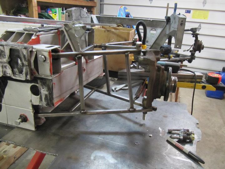
This is the completed front jig. 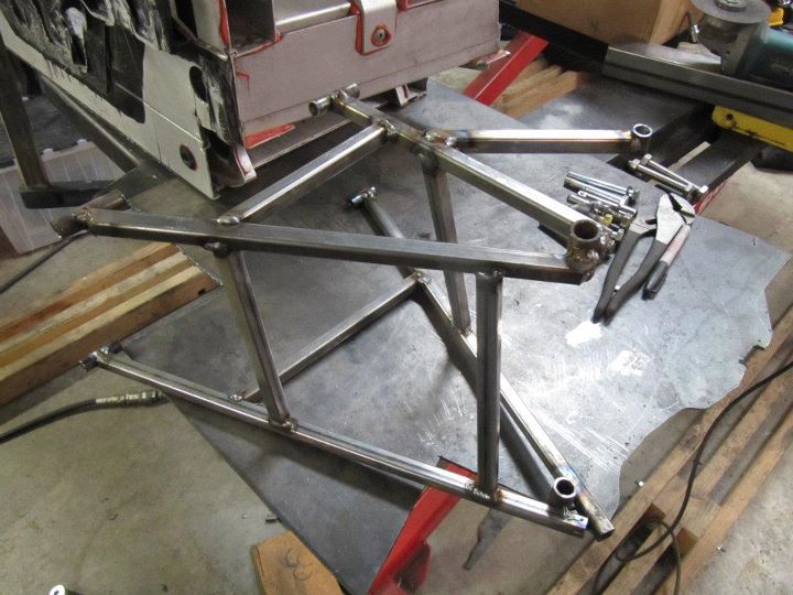
Start of rear suspension mock-up. The lower front mount is actually part of the Lotus chassis and not part of the rear sub-frame assembly so I had locate it separately for the jig to be properly built.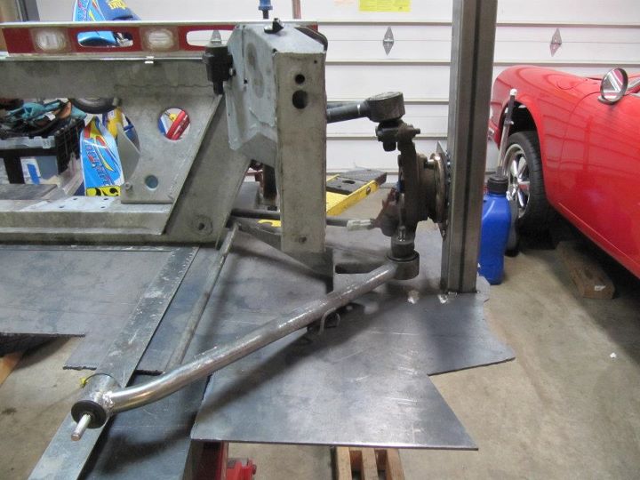
Driver side rear mock-up.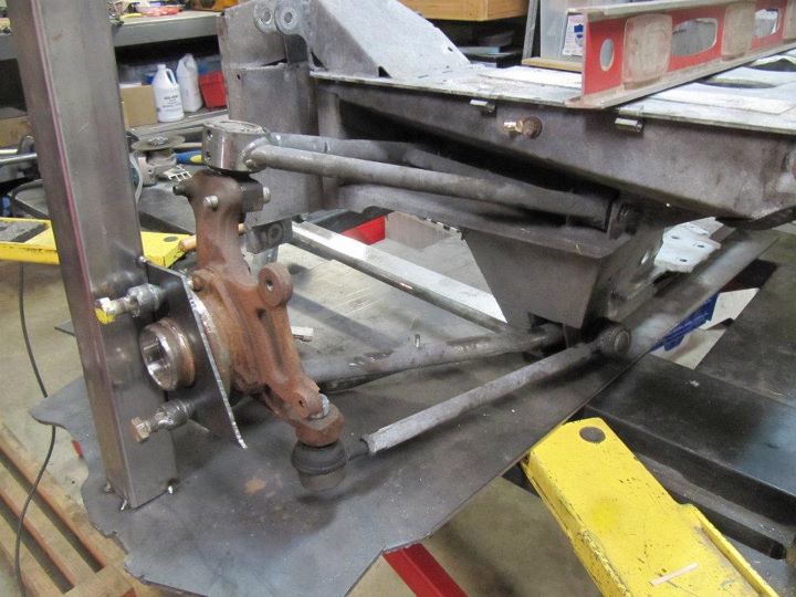
Driver side rear jig in place.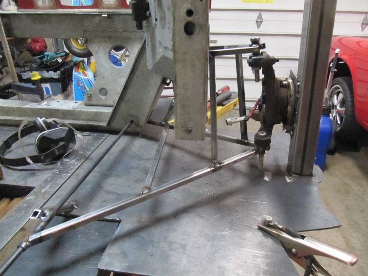
Driver-side front and rear jigs completed. I passed a solid rod through the lower pick-up points and it is interesting that the arm length of both front and rear are the same.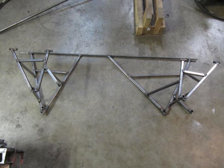
Posted by: Britain Smith Oct 22 2011, 02:01 AM
With the jigs completed, it was time to remove the stock Porsche suspension. It is amazing how much time and effort one can put into the stock set-up and still not overcome the compromises. (Full Rollerbearings, raised spindles, Elephant tie-rod droplinks, S-calipers, Carrera rotors, Wevo strut tower mounts, seam welded control arms, bump-steer rack spacers, etc. etc.)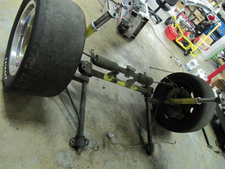
With the stock stuff out of the way, it was time to put the Lotus jig in place. 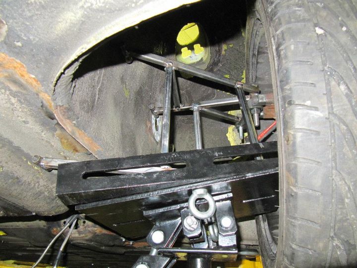
Now....skip ahead 4 days of gruel work...and you get this...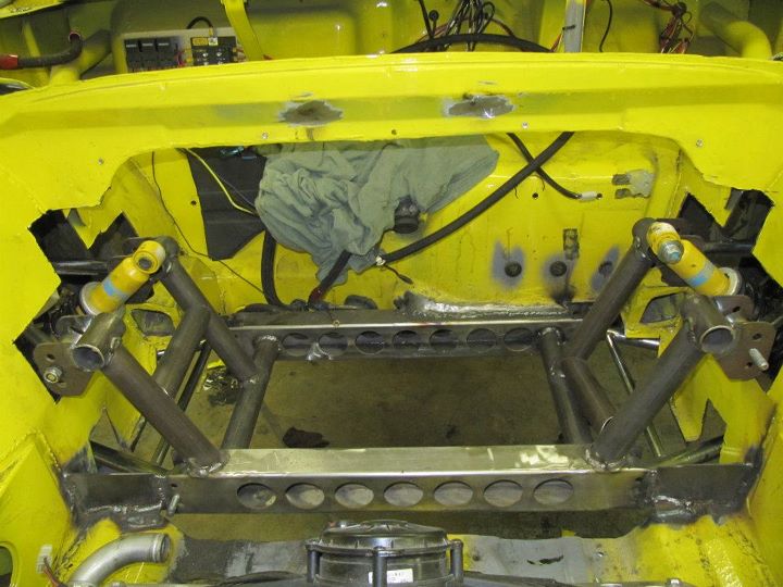
Like I said previously, we did out best to integrate into the stock unibody of the 914 chassis in the spirit of the SCCA rules. Additional support will be added once the shock mounts are completed and the cage is tied in.
Here is the stock Lotus rotor/wheel mounted and suspension set on middle adjustment hole with lower a-arm parallel to the ground.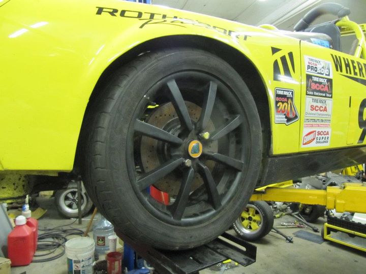
Side shot: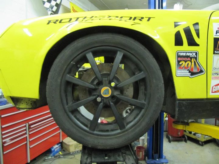
Inside look of the control arms and the lower subframe. One of the days I will strip all the undercoating and make it look all pretty.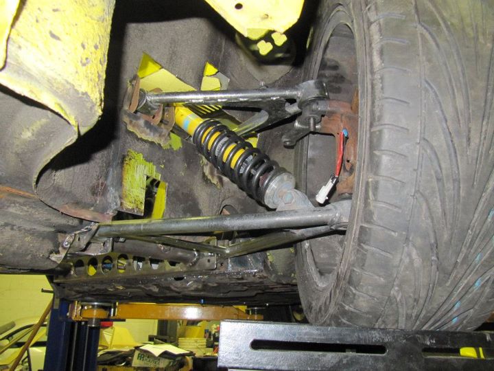
Placement of the steering rack. Adjustment built in to allow for changes in both the control arm height and bump-steer. Again, additional bracing will be added to the mounts as the steering rack takes a lot of force.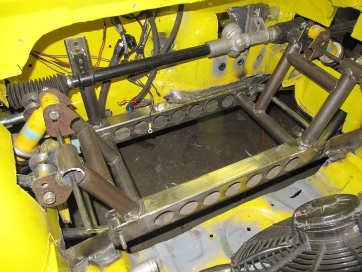
Placement ideas for the front shocks. No, I won't be running two shocks...the outer shock will be replaced by an adjustable push rod and a rocker assembly will be designed and installed in this approximate arrangement.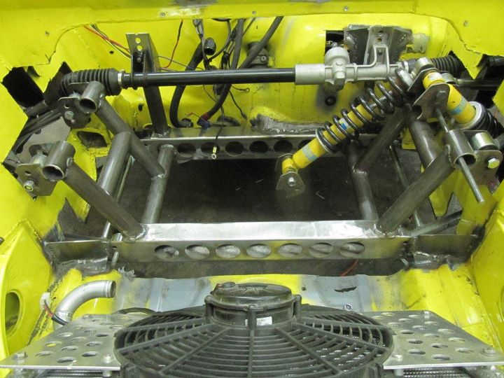
Posted by: Britain Smith Oct 22 2011, 02:04 AM
I have a few additional parts to design and make before completely finishing the front assembly. I will then move on to the rear as I believe that it will be a bit more challenging. With both ends completed, I will cut out the existing cage and built a new one that ties everything together.
-Britain
BTW...all the suspension parts from the car will be sold if anyone is interested.
Posted by: DBCooper Oct 22 2011, 04:03 AM
I'm interested in the suspension. I'll PM.
And again, wow. Wow. Wow.
Posted by: maf914 Oct 22 2011, 08:31 AM
Great work, Britain. Since you are no longer using the 914 inner fender strut mounts will you be cuting away sheet metal for weight savings?
Adding Lotus components to your Porsche 914 chassis made me think of some historical precedents. In the 60's George Follmer attached a Lotus 23 chassis to his Porsche 2.0L and proceeded to win the USRRC championship. Also I want to say that Porsche bought wheels and suspension components from Lotus for some of their early 550 Spyder-type racing cars, but I am not sure of the details, something I read, long ago. These little bits of random information keep swirling around in my head....
Posted by: Britain Smith Oct 22 2011, 10:46 AM
Great work, Britain. Since you are no longer using the 914 inner fender strut mounts will you be cuting away sheet metal for weight savings?
Adding Lotus components to your Porsche 914 chassis made me think of some historical precedents. In the 60's George Follmer attached a Lotus 23 chassis to his Porsche 2.0L and proceeded to win the USRRC championship. Also I want to say that Porsche bought wheels and suspension components from Lotus for some of their early 550 Spyder-type racing cars, but I am not sure of the details, something I read, long ago. These little bits of random information keep swirling around in my head....
I am actually using the inner fender for part of the support of the subframe so I am not sure how much more I will remove. I need to be in the spirit of the XP rules so I don't want to go overboard with tubes everywhere. The material in those fenders is pretty thick and structural so I will take advantage of that.
Regarding the Lotus suspension on early Porsche racecars, I was specifically walking around the paddock at Rennsport Reunion last week taking pictures of early Porsches suspension designs.
-Britain
Posted by: Randal Oct 22 2011, 11:02 AM
I have a few additional parts to design and make before completely finishing the front assembly. I will then move on to the rear as I believe that it will be a bit more challenging. With both ends completed, I will cut out the existing cage and built a new one that ties everything together.
-Britain
BTW...all the suspension parts from the car will be sold if anyone is interested.
Looking good Britain.
Man what a job, unbelievable amount of work.
So the attachment points of that weight reduced subframe are on the body sheet metal (where you can see them in the picture) and where else?
Posted by: Britain Smith Oct 22 2011, 11:18 AM
There are metal plates for the rear crossbar into the frame rails. I will be adding addition plates from the front subframe to the inner fender panels. In addition, there will be tubes from the a-pillar bars of the cage to the front cross member. From that I will add tubing to pick up the upper control arm mounts.
Posted by: campbellcj Oct 22 2011, 11:27 AM
That is just amazing. When you mentioned this project up at Rennsport, I was having trouble visualizing...pictures tell the story nicely.
Posted by: Andyrew Oct 22 2011, 01:11 PM
VERY Nice!
Posted by: Dave_Darling Oct 22 2011, 08:59 PM
There was at least one Lotus-Porsche. There were also a number of Elva-Porsches (three or four were at the Quail last weekend), and of course the famous "Poopers".
The Lotus uprights and brakes were used on the 904s, I think.
--DD
Posted by: campbellcj Oct 22 2011, 09:57 PM
There was at least one Lotus-Porsche. There were also a number of Elva-Porsches (three or four were at the Quail last weekend), and of course the famous "Poopers".
The Lotus uprights and brakes were used on the 904s, I think.
--DD
This is apparently a Lotus 19 with a modified body and a 911 engine. It ran at Rennsport IV.
http://www.flickr.com/photos/cjcam/6263035426/
http://www.flickr.com/photos/cjcam/6263035426/ by http://www.flickr.com/people/cjcam/, on Flickr
Posted by: JRust Oct 22 2011, 10:11 PM
What do we call it now? The ShitsubyusBox
It is looking great Brit! Excellent work as usual
Posted by: J P Stein Oct 23 2011, 11:35 AM
I like it, I like it.......
Posted by: Hontec Oct 24 2011, 03:26 AM
Very, very nice!!!!! good choice the Lotus parts, very strong and light!
take a look at these; even kinky-er!!
http://www.eliseparts.com/products/show/73/570/gt-hub-upright-s2-front-pair/
http://www.eliseparts.com/products/show/73/571/gt-hub-upright-s2-rear-pair/
http://www.eliseparts.com/products/show/92/780/rear-lower-t45-wishbone/
you're not done pimpin"
PS: use the S2 wheelbearings with ABS rings/sensor incorporated and use a racelogic traction control.....you will be truly amazed......
Posted by: Brett W Oct 24 2011, 07:38 AM
So why did we pick the Lotus suspension instead of running a 928 front spindle with custom a-arms and a multilink 996/997 setup in the rear? It would all be Porsche stuff. You built the subframe, so building it using Porsche parts would have been easy.
Posted by: Britain Smith Oct 24 2011, 11:08 AM
Very, very nice!!!!! good choice the Lotus parts, very strong and light!
take a look at these; even kinky-er!!
http://www.eliseparts.com/products/show/73/570/gt-hub-upright-s2-front-pair/
http://www.eliseparts.com/products/show/73/571/gt-hub-upright-s2-rear-pair/
http://www.eliseparts.com/products/show/92/780/rear-lower-t45-wishbone/
you're not done pimpin"
PS: use the S2 wheelbearings with ABS rings/sensor incorporated and use a racelogic traction control.....you will be truly amazed......
Hey Hontec, I have seen those parts....very nice and quite spendy. Maybe someday I will win the lottery and get those.
Regarding the wheel sensors, I am planning on using the stock wheel sensors to integrate ABS onto the car using the Bosch 3-channel or possibly the 4-channel system.
-Britain
Posted by: Britain Smith Oct 24 2011, 11:11 AM
So why did we pick the Lotus suspension instead of running a 928 front spindle with custom a-arms and a multilink 996/997 setup in the rear? It would all be Porsche stuff. You built the subframe, so building it using Porsche parts would have been easy.
At this point it is irrelevant to use the Porsche stuff. I like the Lotus parts because they were built for a lightweight car running 16" wheels. The late model Porsche stuff is why to "beefy" for my needs and would have been significantly more expensive.
-Britain
Posted by: horizontally-opposed Oct 24 2011, 12:15 PM
This is such a wild project. I dig it, and the logic behind it, Britain!
pete
Posted by: Britain Smith Oct 26 2011, 09:13 PM
Thanks Pete. It is moving along quickly. I have listed all the parts I have taken off the car in the classified, lots of very good items.
http://www.914world.com/bbs2/index.php?showtopic=150607
-Britain
Posted by: sean_v8_914 Oct 31 2011, 08:26 AM
I think its new name should be Jason. (Halloween hack and slash fest)
Posted by: DanT Oct 31 2011, 08:41 AM
nice work so far Brit!
looking forward to more progress reports and finally seeing it on all fours again.
Posted by: Hontec Oct 31 2011, 12:27 PM
Very, very nice!!!!! good choice the Lotus parts, very strong and light!
take a look at these; even kinky-er!!
http://www.eliseparts.com/products/show/73/570/gt-hub-upright-s2-front-pair/
http://www.eliseparts.com/products/show/73/571/gt-hub-upright-s2-rear-pair/
http://www.eliseparts.com/products/show/92/780/rear-lower-t45-wishbone/
you're not done pimpin"
PS: use the S2 wheelbearings with ABS rings/sensor incorporated and use a racelogic traction control.....you will be truly amazed......
Hey Hontec, I have seen those parts....very nice and quite spendy. Maybe someday I will win the lottery and get those.
Regarding the wheel sensors, I am planning on using the stock wheel sensors to integrate ABS onto the car using the Bosch 3-channel or possibly the 4-channel system.
-Britain
Britain
Yes they are pricey, but if you're looking for every bit of weightsaving....
Regarding the wheelsensors: take a look at the racelogic traction control system, it uses inputs from these sensors (all 4 wheels) and it will make a difference of day and night to your driving and lap times...........
http://www.racelogic.co.uk/index.php/en/other-products/traction-control
Randall
Posted by: Randal Nov 6 2011, 10:49 AM
Very, very nice!!!!! good choice the Lotus parts, very strong and light!
take a look at these; even kinky-er!!
http://www.eliseparts.com/products/show/73/570/gt-hub-upright-s2-front-pair/
http://www.eliseparts.com/products/show/73/571/gt-hub-upright-s2-rear-pair/
http://www.eliseparts.com/products/show/92/780/rear-lower-t45-wishbone/
you're not done pimpin"
PS: use the S2 wheelbearings with ABS rings/sensor incorporated and use a racelogic traction control.....you will be truly amazed......
Hey Hontec, I have seen those parts....very nice and quite spendy. Maybe someday I will win the lottery and get those.
Regarding the wheel sensors, I am planning on using the stock wheel sensors to integrate ABS onto the car using the Bosch 3-channel or possibly the 4-channel system.
-Britain
Britain
Yes they are pricey, but if you're looking for every bit of weightsaving....
Regarding the wheelsensors: take a look at the racelogic traction control system, it uses inputs from these sensors (all 4 wheels) and it will make a difference of day and night to your driving and lap times...........
http://www.racelogic.co.uk/index.php/en/other-products/traction-control
Randall
Hey Randall - does the racelogic work as an ABS system as well as wheel spin?
How is that project of your coming?
Posted by: Hontec Nov 6 2011, 12:36 PM
Very, very nice!!!!! good choice the Lotus parts, very strong and light!
take a look at these; even kinky-er!!
http://www.eliseparts.com/products/show/73/570/gt-hub-upright-s2-front-pair/
http://www.eliseparts.com/products/show/73/571/gt-hub-upright-s2-rear-pair/
http://www.eliseparts.com/products/show/92/780/rear-lower-t45-wishbone/
you're not done pimpin"
PS: use the S2 wheelbearings with ABS rings/sensor incorporated and use a racelogic traction control.....you will be truly amazed......
Hey Hontec, I have seen those parts....very nice and quite spendy. Maybe someday I will win the lottery and get those.
Regarding the wheel sensors, I am planning on using the stock wheel sensors to integrate ABS onto the car using the Bosch 3-channel or possibly the 4-channel system.
-Britain
Britain
Yes they are pricey, but if you're looking for every bit of weightsaving....
Regarding the wheelsensors: take a look at the racelogic traction control system, it uses inputs from these sensors (all 4 wheels) and it will make a difference of day and night to your driving and lap times...........
http://www.racelogic.co.uk/index.php/en/other-products/traction-control
Randall
Hey Randall - does the racelogic work as an ABS system as well as wheel spin?
How is that project of your coming?
The Racelogic system is purely traction Control. ABS is for people that lack anticipation!
My project was put on hold the last few weeks since I had to put some work into my Honda S2000, hadn't driven it for a year and it needed some love.
Almost done and then back to the 914
Posted by: 914_1.8t Nov 6 2011, 02:43 PM
Awesome project! Can't wait to see the finished result.
Posted by: URY914 Nov 6 2011, 02:52 PM
Looks heavy.
Posted by: Britain Smith Nov 6 2011, 03:07 PM
What we added is less than what we took out. Plus, I need more weight in the front of the car.
-Britain
Posted by: SirAndy Nov 23 2011, 02:41 PM
So, you really think this is gonna make you drive faster?
Posted by: Britain Smith Dec 7 2011, 12:09 PM
Ok guys, sorry for the slight delay in posting updates. I ended up breaking my nose playing basketball and had to get surgery to get it fixed which forced my to cancel one of my trips down to Cali to work on the car. I did however make it down there this past weekend and made good progress.
This first bit of work that I had completed before making the trip down was the inboard shock rocker assemblies. I had the plates waterjet cut and the bearing carriers machined locally. 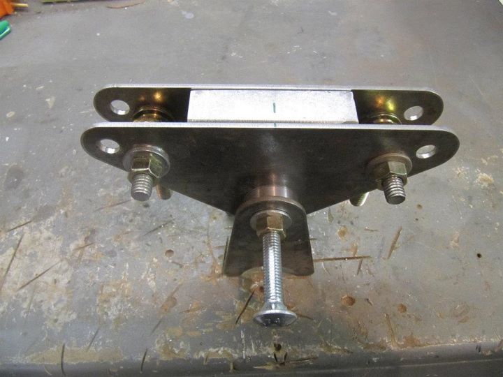
Here are the rockers in place on the car. Still need to complete the pushrod to the control arm and get the shocks that I plan to run.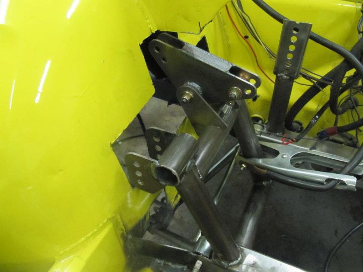
Here is the front suspension rockers viewed from inside the fender wells. I also cleaned up the sheet metal cutouts and made clearance for the steering rack where it passes thru.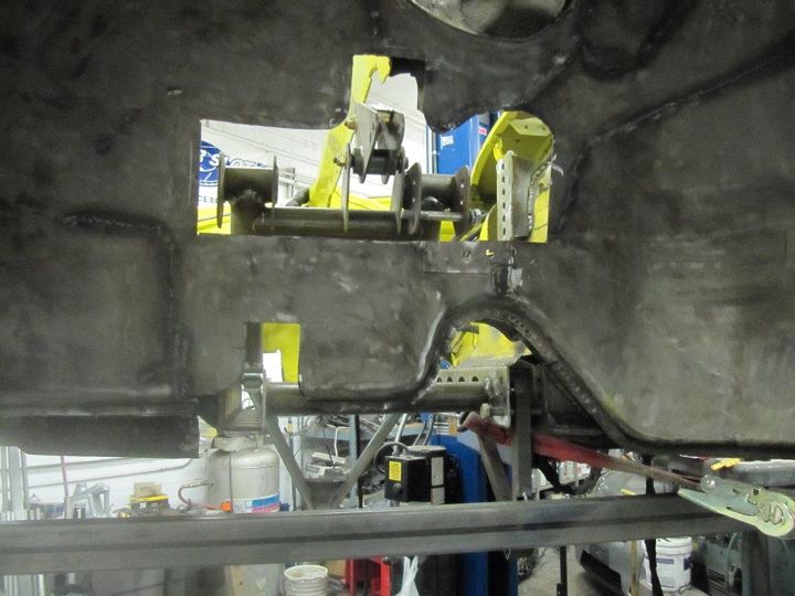
Front fender well with the front suspension jig in place. I mounted this back in place to get the wheelbase measurements to the rear suspension.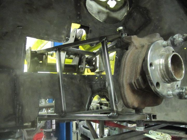
Speaking of the steering rack, the steering shaft is completed. Had to interface between the Lotus splines and the Porsche splines. Both shafts where machined the same diameter and a metal sleeve was made and welded in-between. I had to section the sheetmetal to allow the steering shaft to pass thru when the steering rack is at the upper mounting location.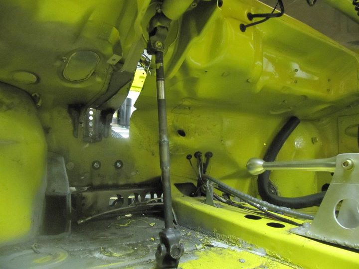
Posted by: Britain Smith Dec 7 2011, 12:27 PM
Now on to the rear suspension.
First up was to cut the front half of the trunk floor and shock towers out.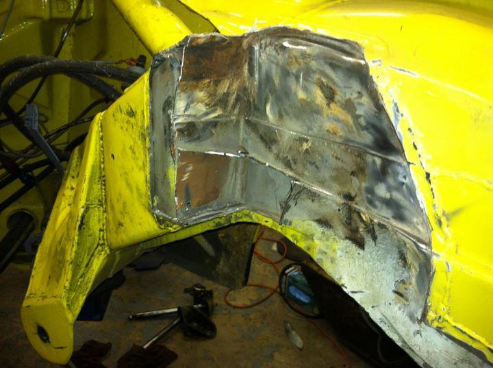
Next we cut out the old trailing arm suspension ears.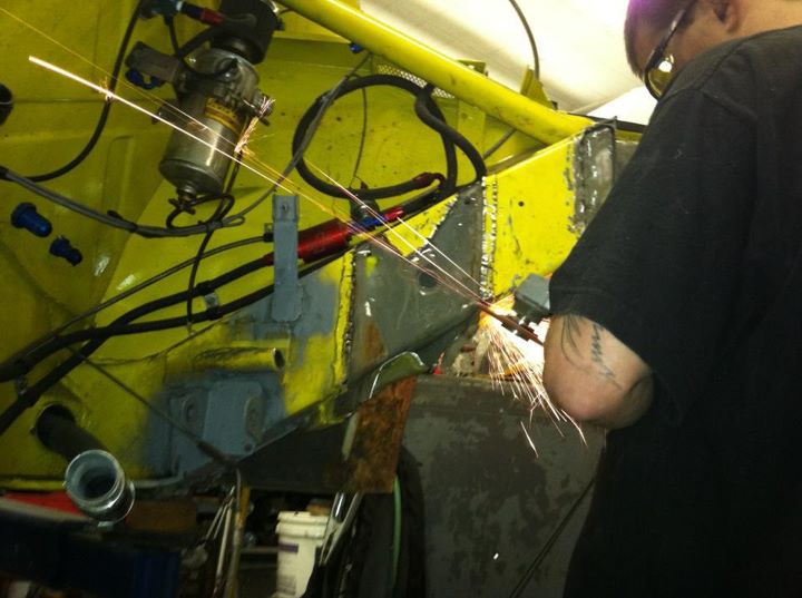
After lots and lots of grinding, this is what we ended up with...lots of space to work with.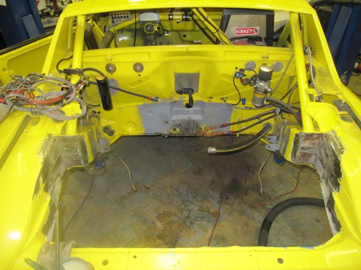
To start, we constructed a jig that runs the entire length of the car and reference the mounting locations for the rear suspension to the front suspension. This allows us to put everything in alignment front and rear and side to side.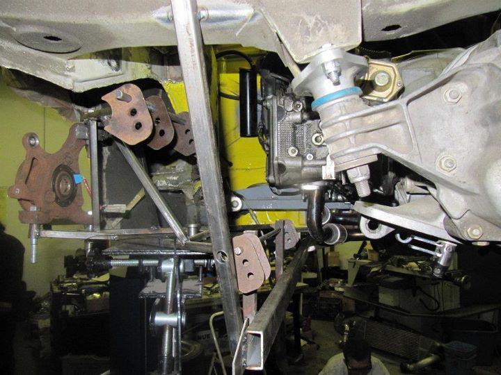
Side view of the location of the rear suspension in reference to the transmission. The custom axles are going to be around 23" long and require a custom outer stub-axle to be machined.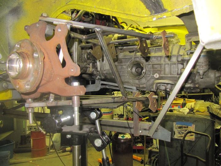
Here you can see the jig running from the front suspension to the rear.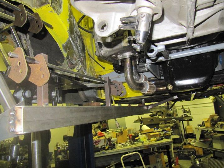
The rear sub-frame will be attached to the car in 6 locations and will hold the complete rear suspension as well as the engine and transmission. This is the lower bar going into place. You can see in the foreground the bung that was welded into the chassis.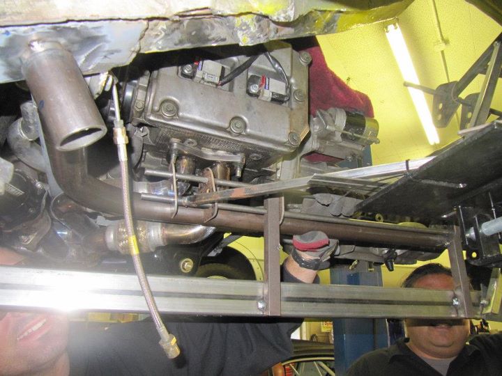
This is Teddy, the owner and machinist at Mavrik Motorsports, the shop where I am constructing this contraption. He is notching the tubing for the rear sub-frame.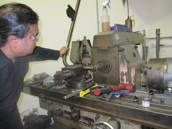
Lower sub-frame bar going into place.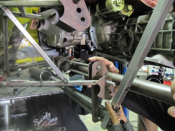
I will be back down there this coming Sat. and the plan is to complete the rear sub-frame and start working on the new cage.
-Britain
Posted by: PeeGreen 914 Dec 7 2011, 12:46 PM
That's a lot of fab work I hope it all pays off. Looks like very nice work Britain.
Posted by: Andyrew Dec 7 2011, 11:12 PM
Wowsers.
To damn cool.
Posted by: plays with cars Dec 9 2011, 12:00 AM
Completely over the top. I bet J.P. had no idea what was in store for his baby when he sold it. (I bet you didn't either )
Posted by: Britain Smith Dec 9 2011, 12:18 AM
Yea, it is an adventure with no end in sight. I talk with JP all the time...we both knew this was coming eventually.
-Britain
Posted by: oldschool Dec 9 2011, 02:19 AM
Yea, it is an adventure with no end in sight. I talk with JP all the time...we both knew this was coming eventually.
-Britain
Very cool man, yeah I know the shop Ted is way cool.
Posted by: bulitt Dec 9 2011, 07:43 AM
Just read your thread and starting from page one noticed the pic of the factory ported intake ports. I don't believe I have ever seen a port job that left the casting marks intact?
Great job! Awesome work!
Posted by: 396 Dec 9 2011, 08:21 AM
I have to add these two simple comments:
*congrats
*one bad ass ride
Posted by: d914 Dec 9 2011, 08:22 AM
I dont think horse power is his problem right now,,, keeping that hp bolted to the ground is!!
Posted by: Britain Smith Dec 9 2011, 11:19 AM
Just read your thread and starting from page one noticed the pic of the factory ported intake ports. I don't believe I have ever seen a port job that left the casting marks intact?
Great job! Awesome work!
My understanding is that they were cast with larger ports as compared to standard 2.0L heads. I agree, they don't appear to be hand ported.
-Britain
Posted by: Britain Smith Dec 9 2011, 11:21 AM
Yea, it is an adventure with no end in sight. I talk with JP all the time...we both knew this was coming eventually.
-Britain
Very cool man, yeah I know the shop Ted is way cool.
I will be back down in SoCal this Sat. thru Tuesday...come by and check it out.
-Britain
Posted by: J P Stein Dec 9 2011, 11:32 AM
Brit continues with the mantra of "It's never done" or continuous improvement ....pick one. My spirit was strong but my wallet was weak.
The car did OK for with my low rent efforts but Brit is moving to a higher level......but it still requires development. No instant gratification here..just a lot of hard work. I am confident that he will make it work.
Posted by: Cap'n Krusty Dec 12 2011, 10:11 AM
Braved the 605 and the 5 Saturday to see the project. Amazing attention to "how stuff works". Gonna end up with an insane power to weight ratio in a chassis that should handle like a slot car. Impressive! I look forward to seeing it run some events.
The Cap'n
Posted by: Randal Dec 12 2011, 10:28 AM
What's the schedule for the car Britain, i.e., are you planning any early events in 2012?
Excellent planning and execution.
Posted by: Britain Smith Dec 13 2011, 03:14 AM
The current goal to have the car ready for testing by mid-Feb. Based on the amount that we got done in the last few days, that goal is feasible. I fly back to Portland tomorrow and I will have some time to post some new pictures. Wait till you see what we got done on the rear suspension...it is amazing.
-Britain
Posted by: Britain Smith Dec 13 2011, 11:17 PM
Just got back from another 4 days in sunny SoCal working on the racecar. 12-15hrs days, but we got a lot done. Check it out.
Lower bars of the rear sub-frame completed. These two bars took 5 attempted to get right. They had to contact 4 points with two compound bends and angled cuts. They intersect the frame rails in the front and the transmission mounts in the back.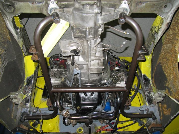
Side view of the lower sub-frame in place without the engine and transmission in place. Used an extra 901 nosecone to locate the transmission mounts.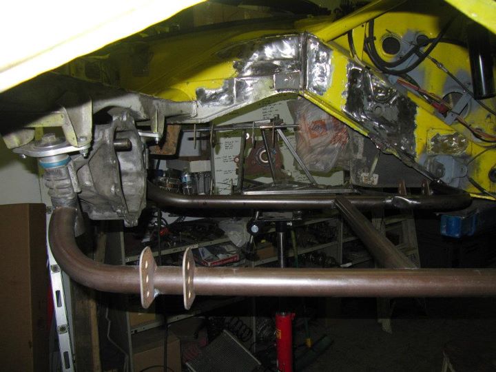
Jigs in place to locate the proper pick-ups points for the upper mounts. The upper mounts are in-board 1/4" to achieve more negative camber compared to a stock lotus.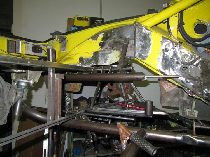
Rear suspension control arms in place at the upper pick-up point. Additional rear body mount added for the upper mount bar to hit the chassis.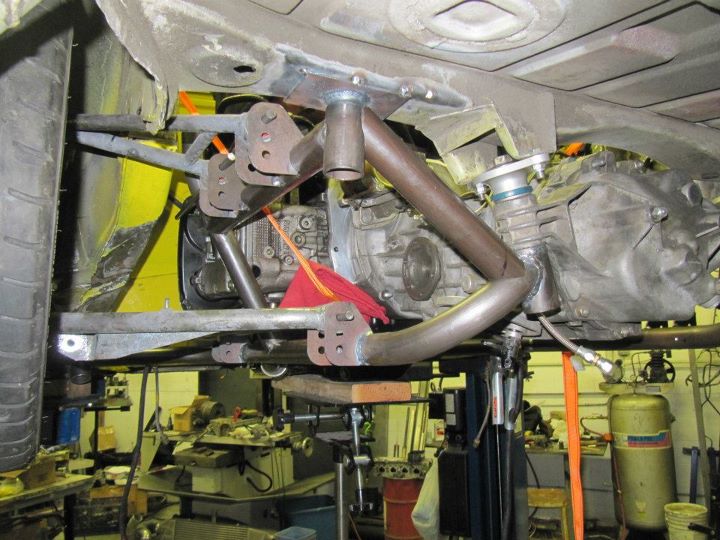
Rear Lotus wheel mounted on the car.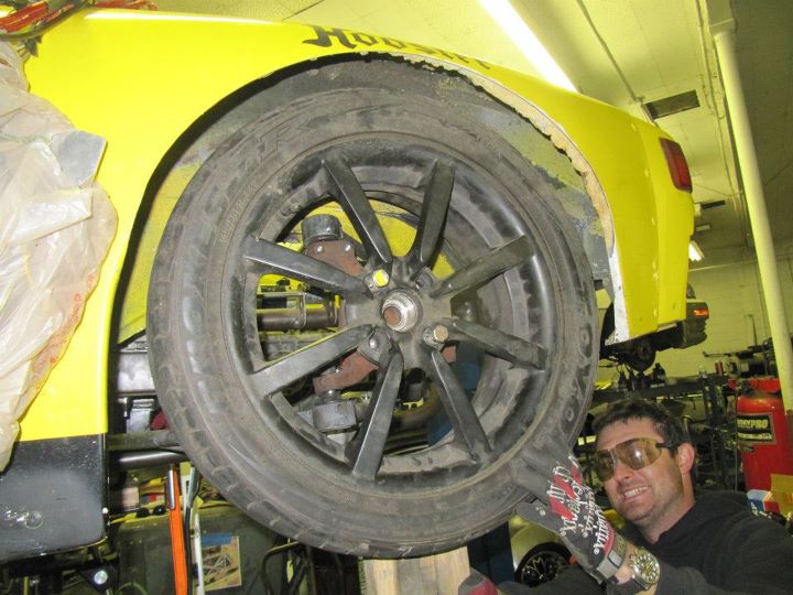
Posted by: Britain Smith Dec 13 2011, 11:19 PM
The rear sub-frame will also be a cradle for the engine mounts. This will free up some much needed room in the front of the engine. These utilize the stock Subaru engine mount parts with a few modifications.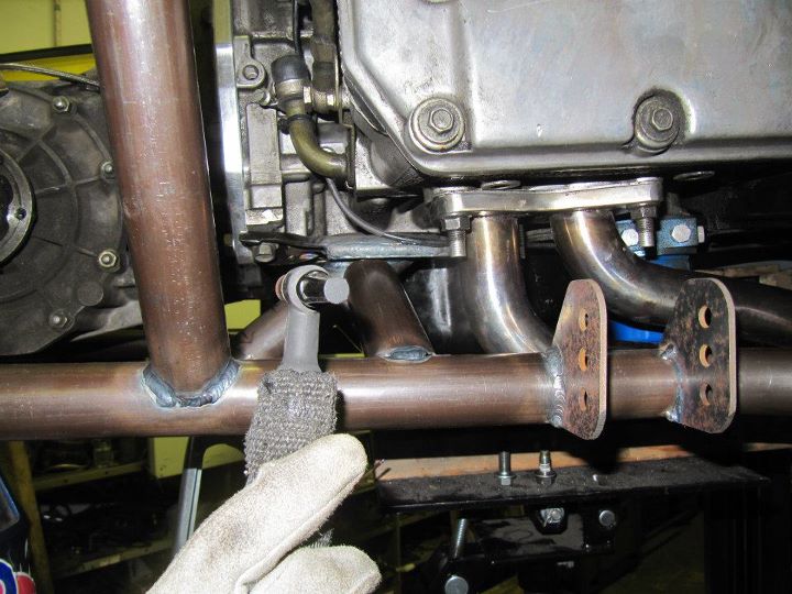
Engine in place in the new sub-frame and bolted to the car. There will be an additional cross-bar in place between the frame rails.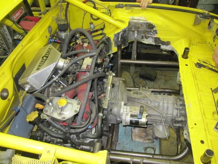
The sub-frame will unbolt from the car and the engine, transmission, and rear suspension will come out as one piece.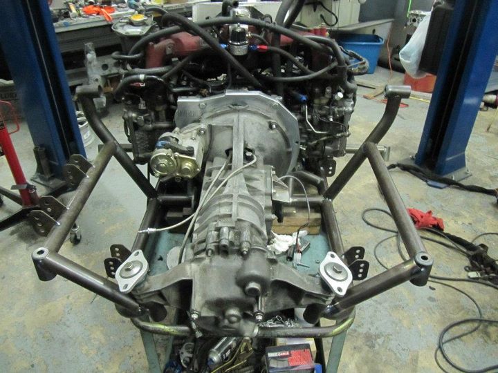
Side view of the sub-frame. The will be an additional bar across the front of the engine to support the turbo and other items that used to be mounted to the old crossbar.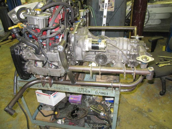
Completed rear sub-frame in place in the car for final welding. Here you can see the new engine mounts.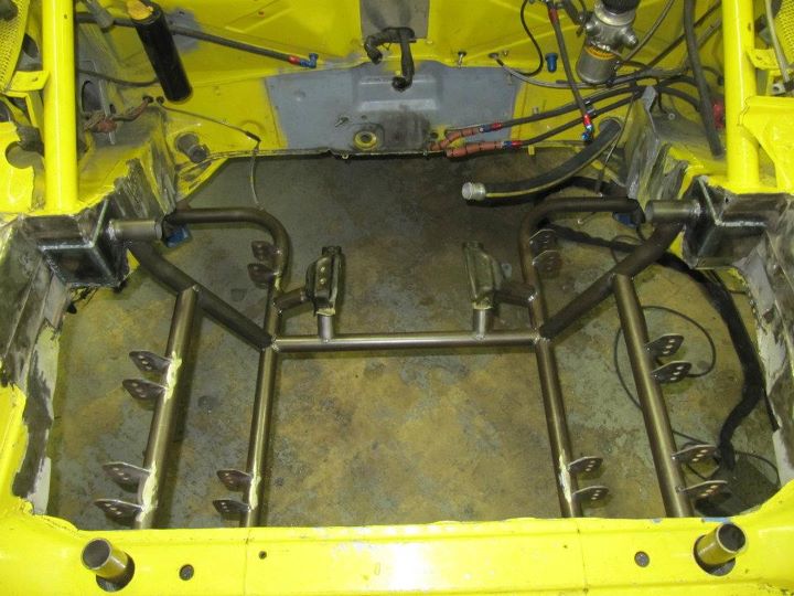
Posted by: Britain Smith Dec 13 2011, 11:22 PM
I knew the day would come sooner or later, but here we are cutting out the old cage.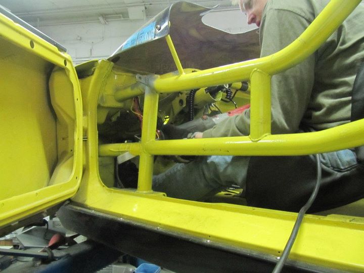
The old cage was 1.75" x 0.120" and weighed in at 92lbs. It was a bit heavy as you can tell from my expression here.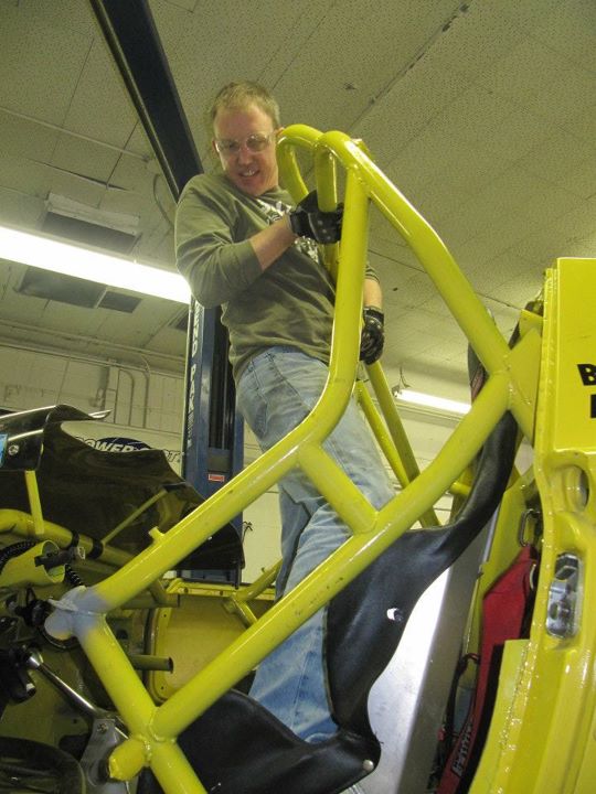
Pile of bars from the old cage. 92lbs of steel sitting here. I estimate that the new cage will be approximately 50lbs.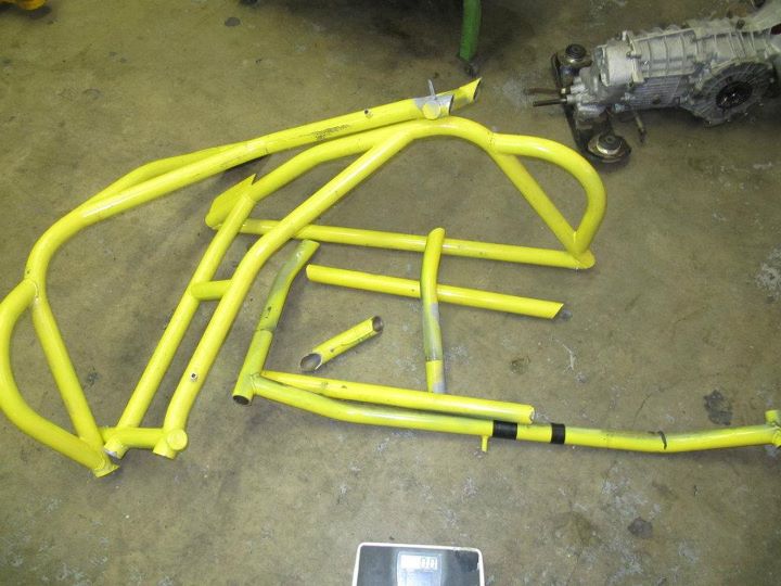
View from the rear without the cage. The new cage will tie in the frame rails as well as the two bars sticking up in the rear which are the upper sub-frame mounts.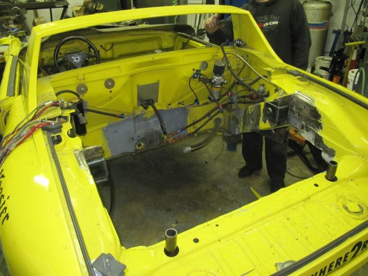
Additional structure related to the old suspension cut out of the front. Material will be added back to the wheel wells and the cage will extend forward to pick-up the front suspension assembly.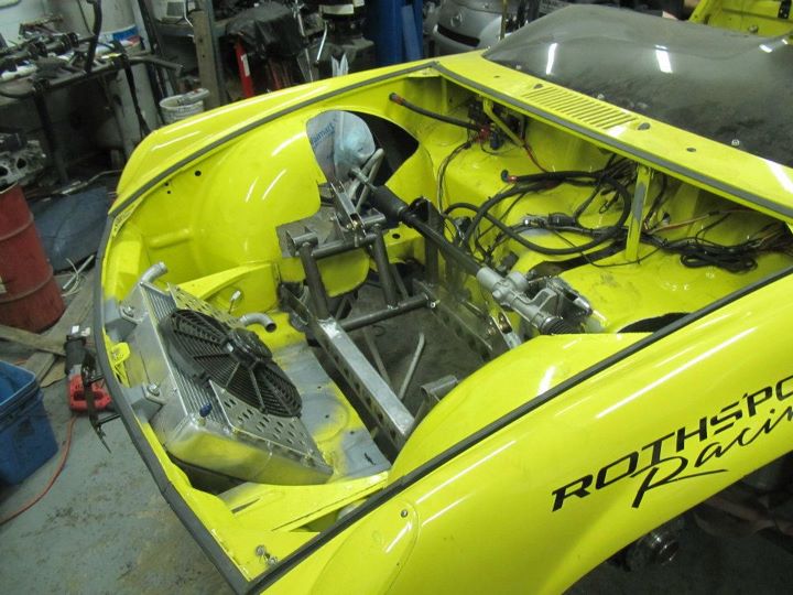
Lotus steering rack in place and excess 914 sheet metal removed.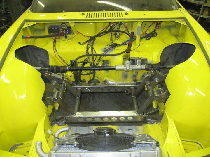
Lots more room in the car with the cage removed.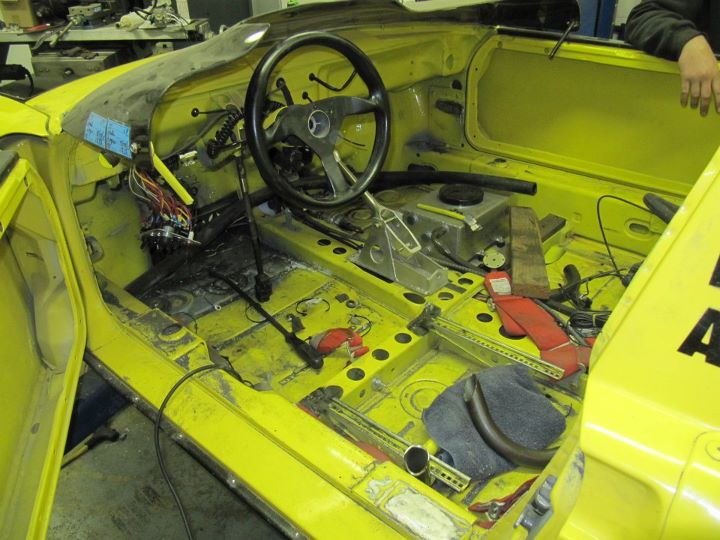
Next step is to construct the new cage and start putting the car back together.
-Britain
Posted by: ChrisNPDrider Dec 14 2011, 10:28 AM
wild
Do you think the new "system" will accelerate or slow engine or transaxle removal?
Critical decision: paint the new cage to match the suspension sub-frame, or in a contrasting color?
Posted by: Britain Smith Dec 14 2011, 11:03 AM
The removable sub-frame should make the engine removal much quicker since the I won't have to disconnect the axles or any of that stuff. I plan to add quick disconnects for the brake lines, but I will still have to deal with the radiator lines.
-Britain
Posted by: Andyrew Dec 14 2011, 03:50 PM
Awesome
You will be running the porsche wheels with the new tires correct?
Posted by: Britain Smith Dec 14 2011, 04:04 PM
Nope. The Lotus stuff is 4x100 so I will be ordering all new wheels...which are wider
All my old wheels are for sale if you are interested....see the classifieds.
-Britain
Posted by: yeahmag Dec 15 2011, 11:48 AM
Where are you doing the build? I'd love to drop by and see it in person...
Posted by: Britain Smith Dec 15 2011, 11:54 AM
It is at Mavrik Motorsports in Fullerton.
-Britain
Posted by: yeahmag Dec 15 2011, 12:01 PM
Heading down to Costa Mesa R&D on Saturday so I'll be driving right by there (well, close anyway). Let me know if it's acceptable to drop in. Not sure I'll have time, but just in case...
Posted by: Britain Smith Dec 15 2011, 12:03 PM
I am sure it won't be a problem, I won't be there...but the car is.
_Britain
Posted by: 396 Dec 16 2011, 12:06 AM
It is at Mavrik Motorsports in Fullerton.
-Britain
Is it ok to stop by and see the monster
Never mind- just noticed your response - thanks
Posted by: Britain Smith Dec 16 2011, 12:22 AM
Just booked another flight down there for Jan 7th thru the 10th....maybe we should hold a BBQ or something.
-Britain
Posted by: yeahmag Dec 16 2011, 01:24 PM
Sounds great to me! I'd be happy to host it in Pasadena if we need a spot.
Posted by: Britain Smith Dec 16 2011, 01:28 PM
We would just do it at the shop...I can't spare much time away from working on the car, I am only there for 4 days.
-Britain
Posted by: oldschool Dec 16 2011, 03:48 PM
We would just do it at the shop...I can't spare much time away from working on the car, I am only there for 4 days.
-Britain
Posted by: Britain Smith Dec 16 2011, 03:52 PM
Ah great, gotta get the car done so there is something good to look at!
-Britain
Posted by: Britain Smith Jan 5 2012, 01:00 PM
I will be returning to So-Cal this weekend for another few days of car-building fun. On Sunday we will be holding a http://forums.pelicanparts.com/porsche-911-used-parts-sale-wanted/648137-fs-part-out-party-84-carrera-targa-so-cal.html for my co-owners '84 Carrera, you guys are welcome to come by and check out the racecar and/or get any 911 parts you need for "other" projects.
The shop is:
Mavrik Motorsports
3811 Artesia Ave
Fullerton, CA 92833
This trips plan is to get the cage done and hang all the suspension on the car to make it a roller.
-Britain
Posted by: JRust Jan 5 2012, 01:35 PM
Sounds good Brit! Keep those pics coming
Posted by: Twystd1 Jan 14 2012, 02:41 AM
Hey Britt.
I will be there to help as well at the end of the month.
And I am bringing some tools, clamps and magnetic angles as well.
Thanks for letting me touch your car. That was serious fun bro.
Clayton
Posted by: Britain Smith Jan 14 2012, 02:45 AM
No problem Clayton...you were some serious help...I owe you a 6-pack. I will be there Feb 2nd, we will be in touch.
-Britain
Posted by: Britain Smith Feb 8 2012, 05:27 PM
Sorry about the lack of updates. I have since made two trips back down to California to work on the car and have made pretty good progress. As always, I had hoped to be further along at this point that I am but I am about 90% there.
First off, the new cage is coming together nicely. The regulations to get my head under the cage and to meet the broomstick rule forced me to mount the seat lower and farther back and raise both the main hoop and the a-piller bar under the windscreen.
Here is the cockpit area.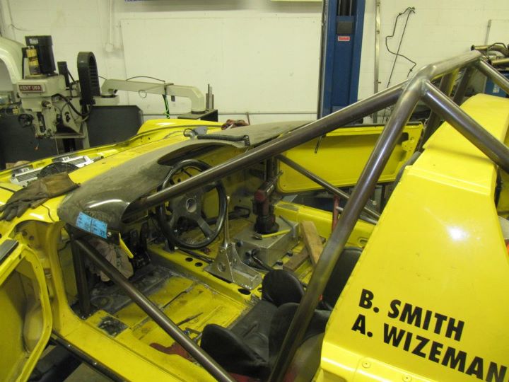
You can see how high the front a-piller bar is now.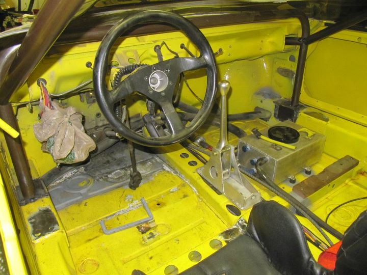
The raised main hoop and the rules around the downbars forced me to either cut the targa bar or go over it...I decided to go over it and pick-up the rear suspension point.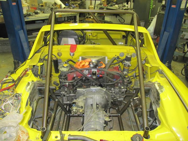
In the front, two bars extend from the top of the a-piller to the front suspension sub-frame. There will be two additional bars from the lower part of the a-piller forward that still need to get done.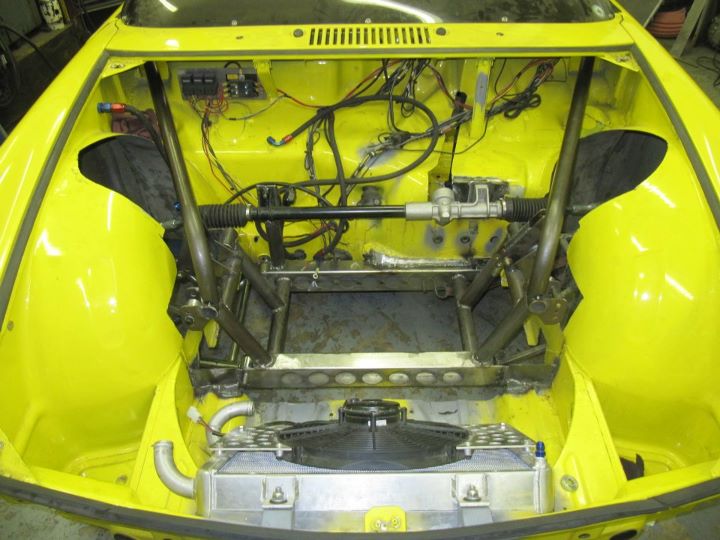
Posted by: Britain Smith Feb 8 2012, 05:31 PM
Back on the rear sub-frame. Additional bars added to the rear lower subframe to strenghten the structure and triangulate everything.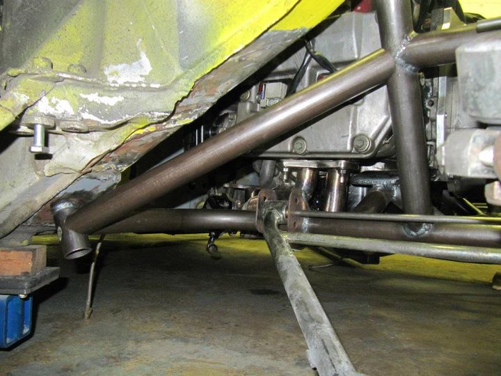
And the other side.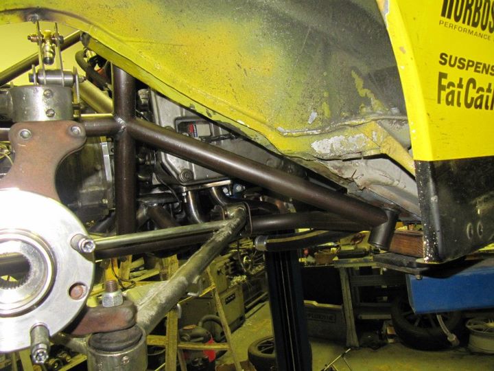
A bar was added over the transmission and tie in the two sides of the rear sub-frame.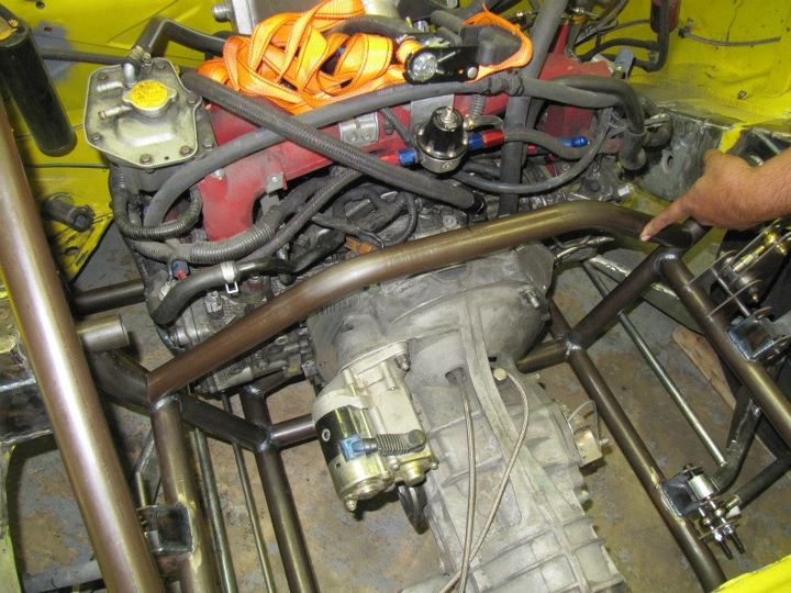
Another bar under the rear of the transmission that can also serve as a jack-point.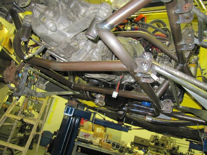
And finally a turbo mount bar that snakes up above the header and will help tie together the subframe.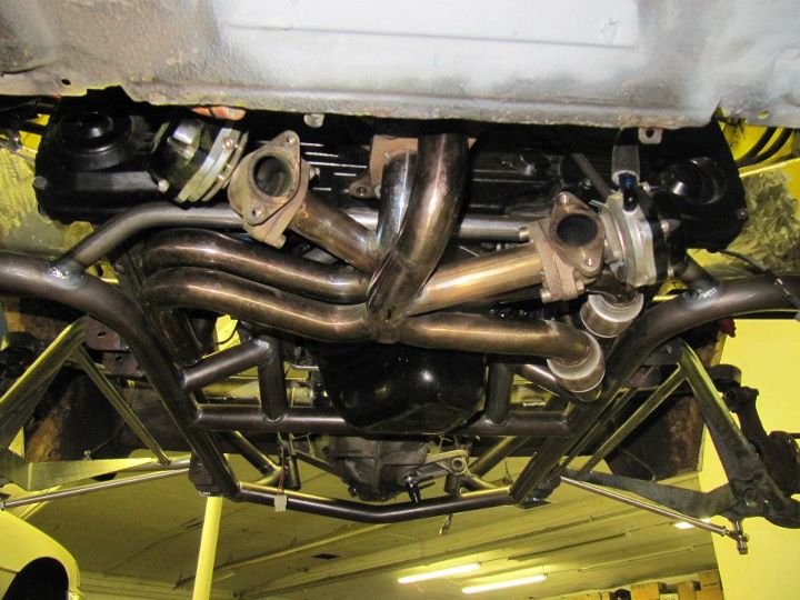
Posted by: Britain Smith Feb 8 2012, 05:35 PM
It is always the small stuff that takes up all the time. I had to make a new seat bracket, relocate the pedal assembly, make a hold for the dash off the a-piller bar and a couple of other small things.
Here is the relocated the ECU to the passenger firewall. I will need to construct a nice cover to keep it out of the elements. Fortunately I only had to rewire a handful of the wires to move it and the old panel worked perfectly.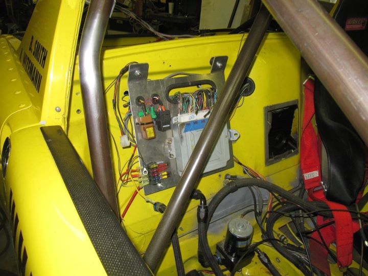
Fuel tank relocated to the passenger footwell with the fuel pump mounted right under it. This will keep it out of the heat from the radiator. I will need to construct a bulkhead to comply with the rules.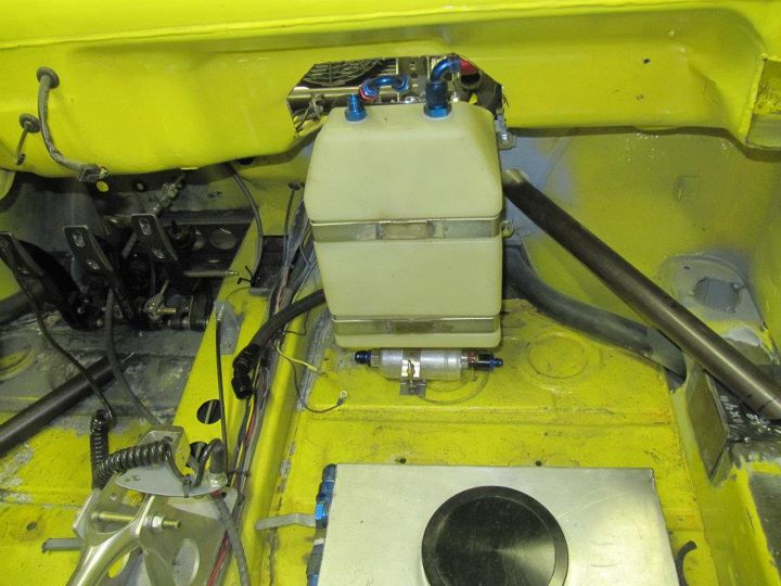
New front trunk floor. This panel is structural to hold the front of the car together.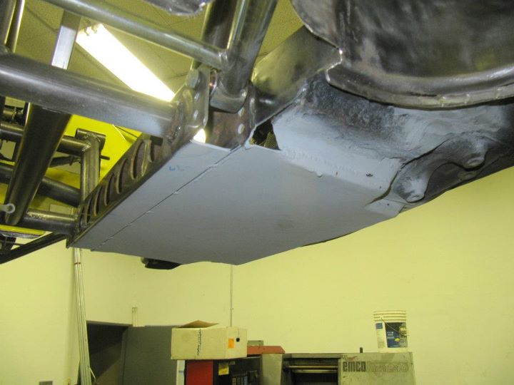
Posted by: Britain Smith Feb 8 2012, 05:38 PM
And now to the good stuff.
Front suspension geometry completed and shock mounted for fitment. 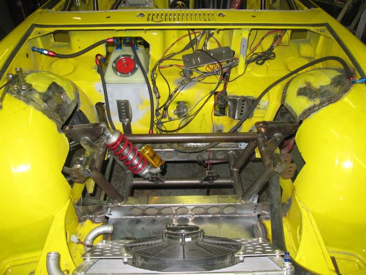
Front suspension with two bar in place to simulate shocks. We will use the to get the approximate corner weights and get the new shocks valved.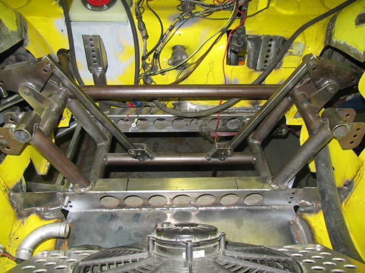
Outboard struts for the inboard rockers. These are adjustable so we can play with ride height.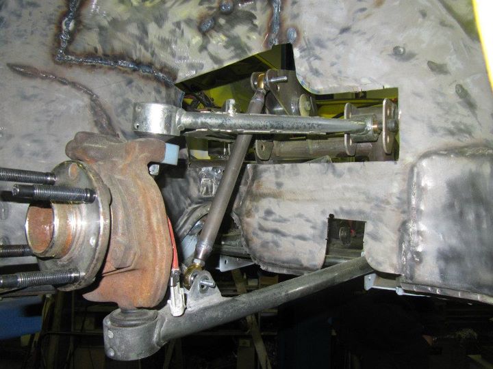
New Bogart wheels with some old slicks mounted. Front weighed in a 38lbs with tire. These are 11" tires on a 10" rim.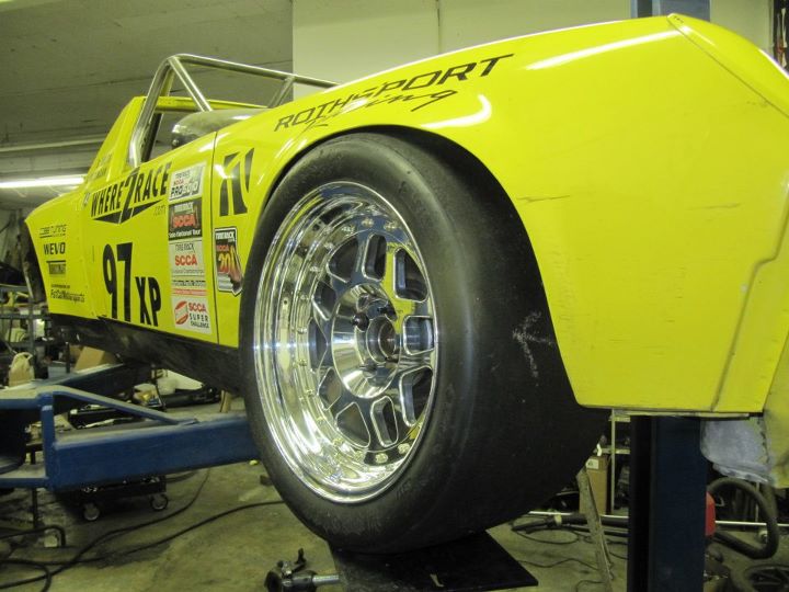
Now that is what I am talking about...front meat!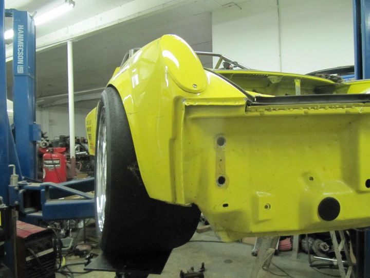
Bogart wheels look great...might have to do a little bodywork mods.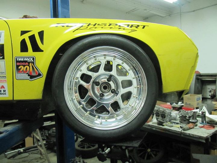
Posted by: Britain Smith Feb 8 2012, 05:41 PM
I love this shot...looks like the rear of a Porsche 908 with all the exposed suspension parts. Both rear toe links completed and everything bolted up. Need to complete the shock mounts and this thing will be on the ground.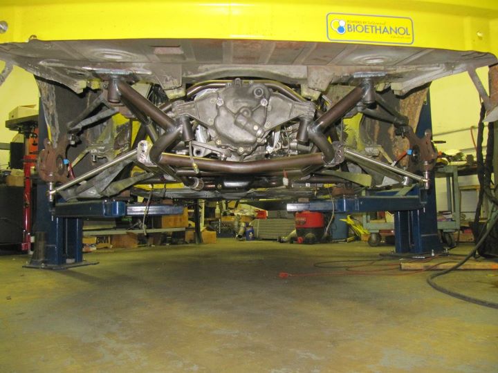
Lots and lots of work put into this rear sub-frame assembly. You can also see the new battery mount.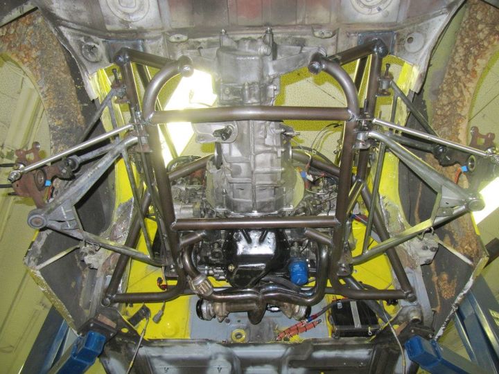
Rear Bogart wheels mounted. These are 12" slicks on an 11.5" rim. These weigh in a 42lbs with tire.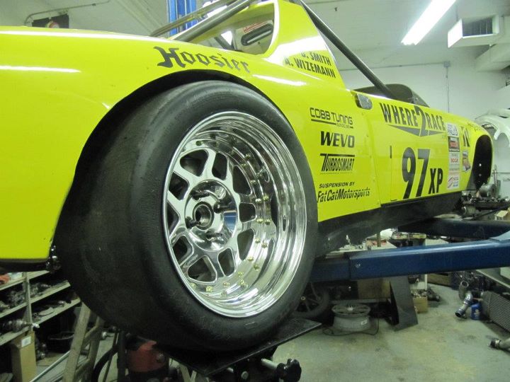
Inside of the rear wheels. Still need to get some custom axles made.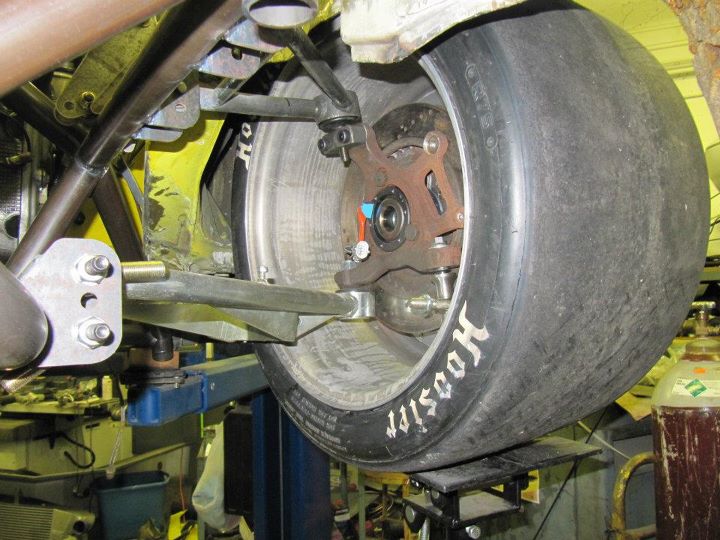
Custom rear toe links that a combination of Nitron outboard heim joints and custom toe link bars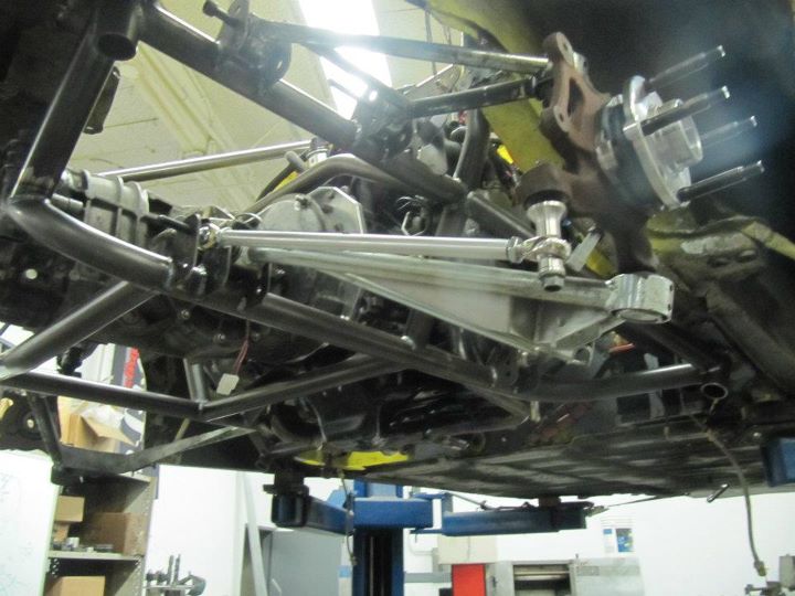
Approximate location for the rear shocks. Ran out of time to get them mounted so I will have to make another trip down to finish things up.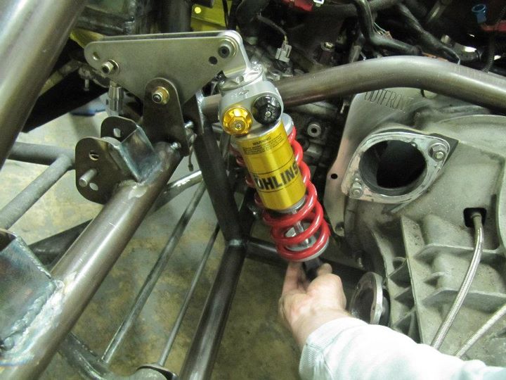
Posted by: Elliot Cannon Feb 8 2012, 07:53 PM
Hey Britt.
I will be there to help as well at the end of the month.
And I am bringing some tools, clamps and magnetic angles as well.
Thanks for letting me touch your car. That was serious fun bro.
Clayton
And you are???
Posted by: JRust Feb 8 2012, 08:46 PM
Insanity Brit! Holy crapola what a job. Nice work man. It's looking great
Posted by: Randal Feb 8 2012, 10:30 PM
Just outstanding Britain. Can't wait to see it run.
Posted by: ChrisNPDrider Feb 9 2012, 02:47 PM
Nice job recruiting NARPsters for your NARP
Have you ever seen another 914 before this one go OVER the targa bar on both sides with the roll cage?
AWEsome work, appreciate all the sharing of the race car development
Posted by: Britain Smith Feb 9 2012, 02:48 PM
Nice job recruiting NARPsters for your NARP
Have you ever seen another 914 before this one go OVER the targa bar on both sides with the roll cage?
AWEsome work, appreciate all the sharing of the race car development
Nope, never seen the cage over the targa bar and honestly it is growing on me.
-Britain
Posted by: PeeGreen 914 Feb 9 2012, 03:16 PM
Wow that cage makes the car look so much better. Glad you HAD to get rid of the old one. Work looks good.
Posted by: bernbomb914 Feb 9 2012, 05:14 PM
WOW any resemblance to a 914 is purly accidential. you will scare a lot of the high priced racers to DEATH
Posted by: Britain Smith Feb 29 2012, 05:46 PM
Good progress on the car this last weekend. Got the rear suspension geometry all worked out and the shocks mounted, fuel tank enclosure done, most of the cage welded in and bolted up all the suspension components to the car and actually put the car on the ground.
The goal is to get the car out for shake-down runs on my next trip down there. We shall see if that happens, still need to get a couple of custom components made and I am hoping everything fits.
Here is the rear sub-frame completed with the rear shock mounts in place and the control arms all bolted on. Sitting on the bench, it looks awesome.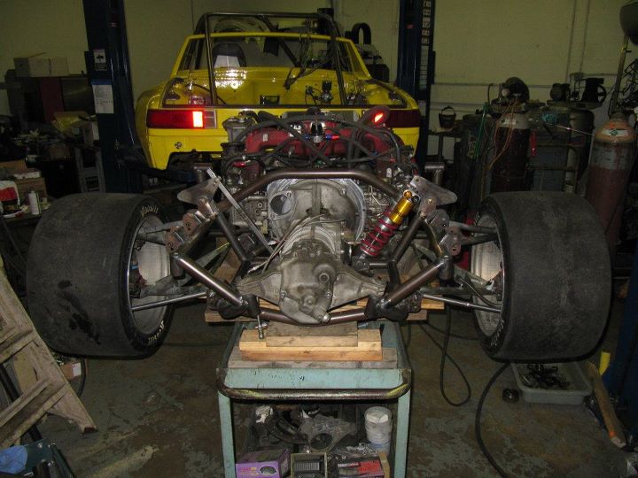
Rear rocker mount completed and shock in place. The final shock length will be longer for the correct motion ratios.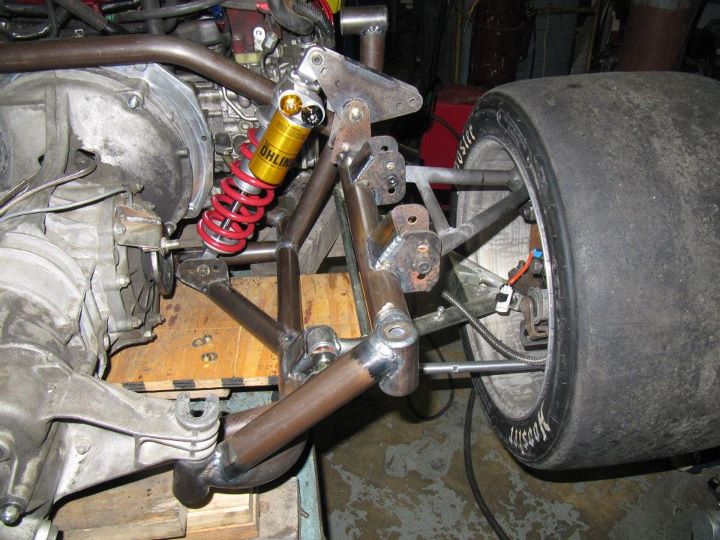
Rear sub-frame going back into the car. We will put quick-disconnects on various lines to make the process a bit easier.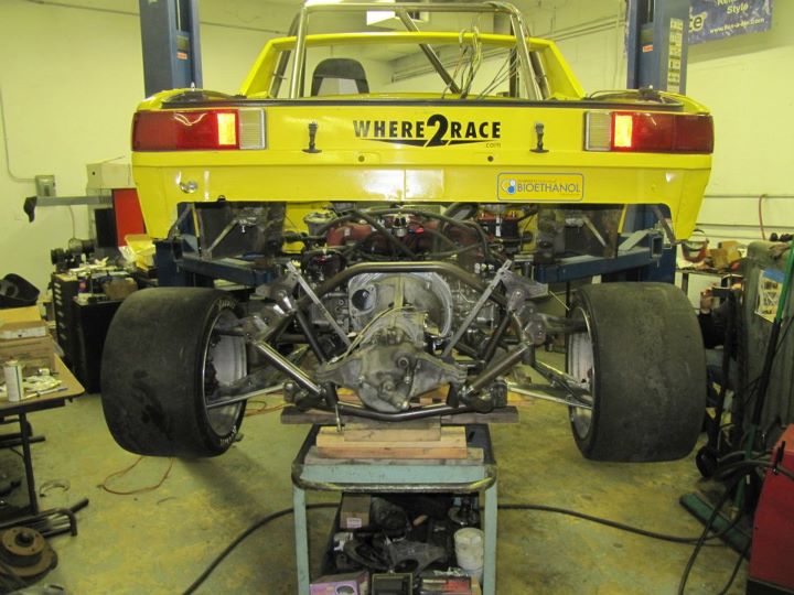
Rear sub-frame assembly from underneath. Two bars added to support the shock mounts. The assembly is very strong and comes in and out with ease.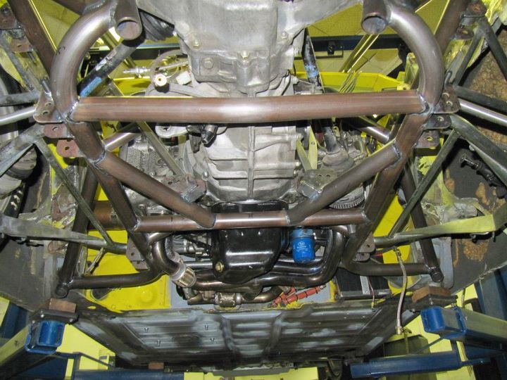
Posted by: Britain Smith Feb 29 2012, 05:50 PM
Due to lack of space in front trunk and the fact that I need to keep the fuel away from the hot radiator air, I move the fuel tank into the passenger compartment and built an enclosure since it must be fully sealed.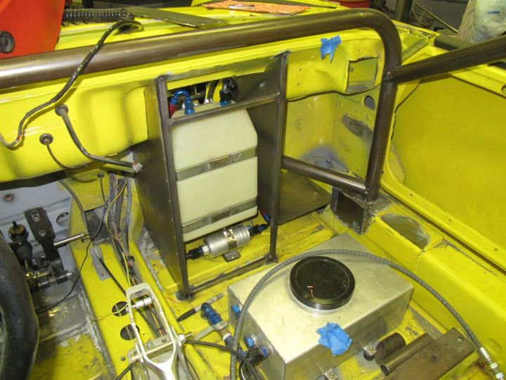
View of the enclosed fuel tank from the front trunk.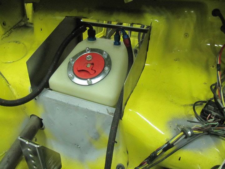
Another view of the fuel tank enclosure. You can see that it is also enclosing the passenger side radiator line and just inside of the cage bar going to the front suspension.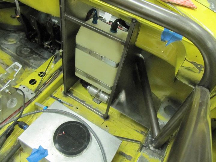
Fuel tank enclosure all welded up.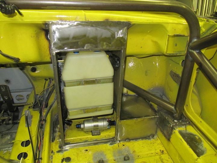
Fuel tank enclosure with the access door mounted.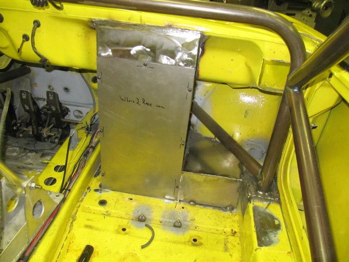
Posted by: Britain Smith Feb 29 2012, 05:54 PM
Most of the cage welded in. Still need to weld in the petty bar, the harness bar, and two bars to the top of the front suspension assembly.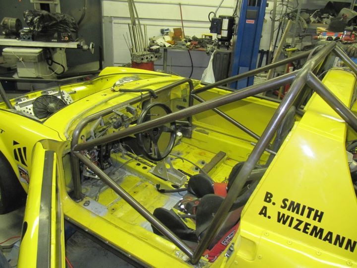
Another view of the cage and the kick-ass Rothsport Quick Disconnect for the steering wheel.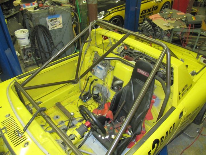
Front view of the cage and front suspension.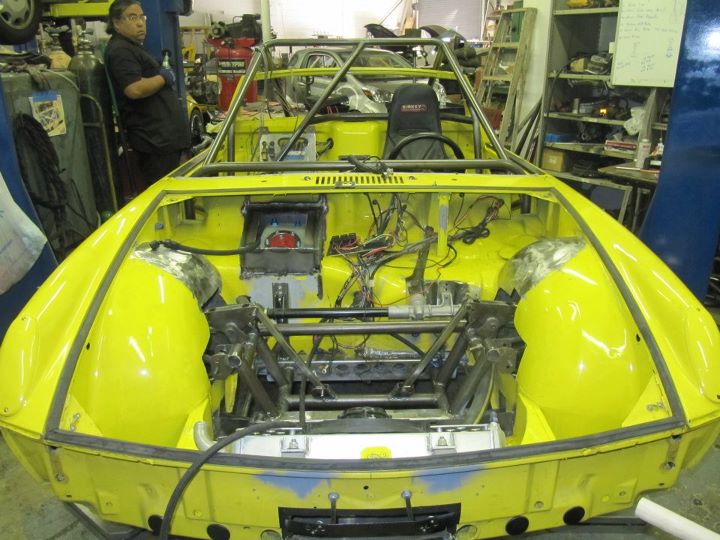
Front suspension installed with the steering rack in place. Need to decide where I am going to mount the electrical panel and tidy up the radiator lines. You can also see the fuel tank enclosure door in place.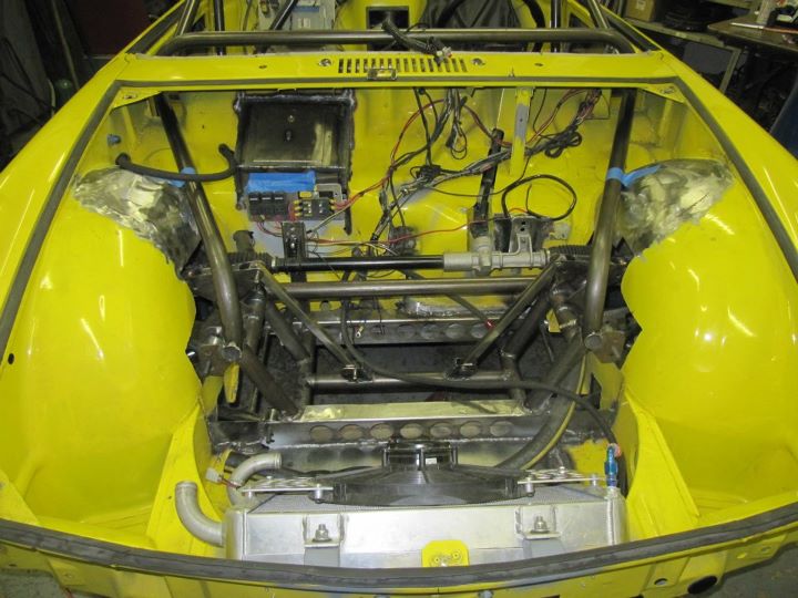
Side view of the front trunk.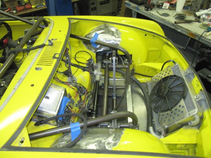
First iteration of exhaust routing. I don't have room to go backwards thru the suspension area so this seems to be the best route.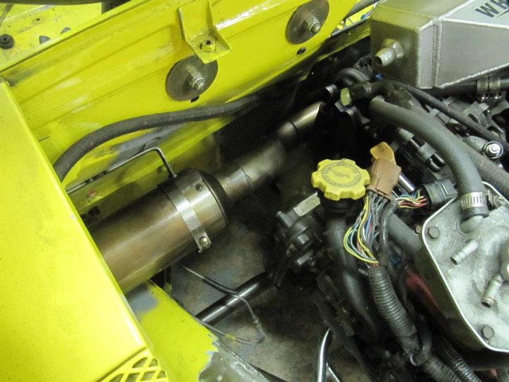
View of the exhaust routing with the water line in place. Still need to complete the wategate dump back into the exhaust stream.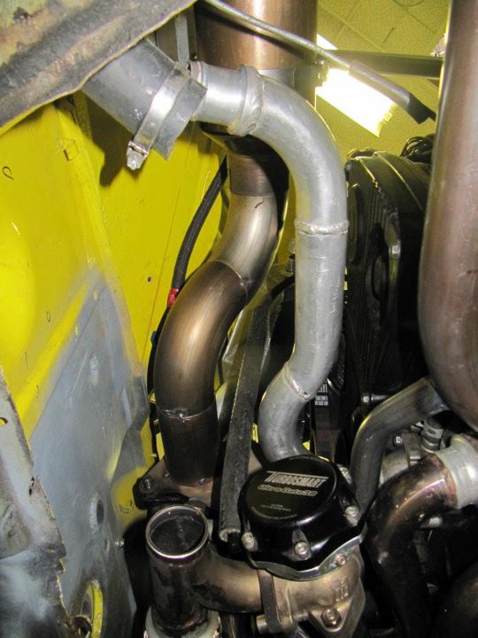
Exhaust routing into the fender well area. It will dump outside the fender and allow for additional mufflers to meet sound regulations.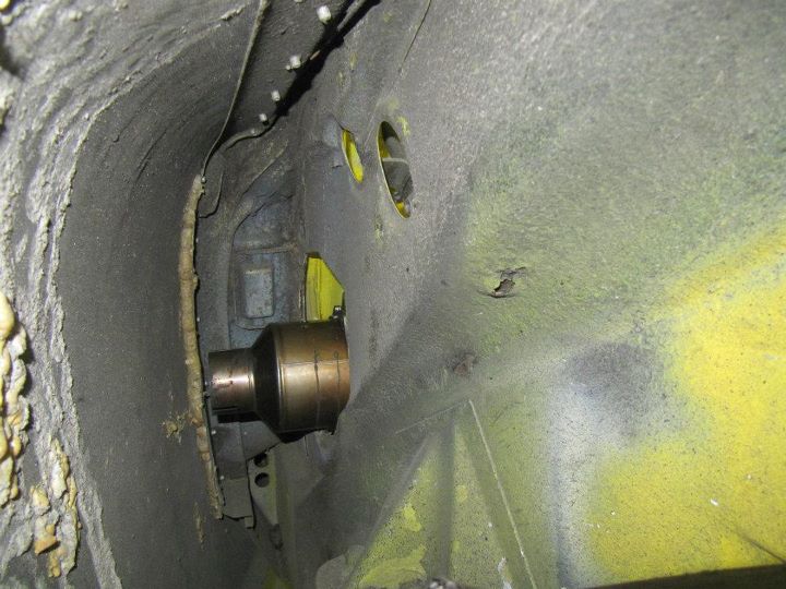
Top view of exhaust routing.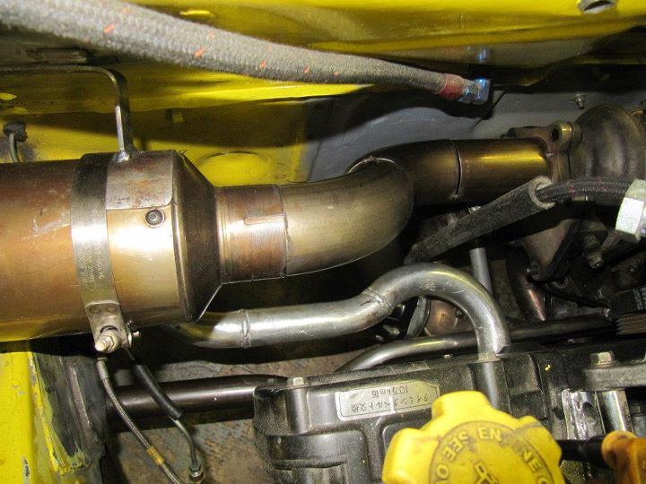
Still a lot of work to get done, but progress has been steady and I can't wait to drive it.
-Britain
Posted by: DBCooper Feb 29 2012, 06:36 PM
You know Britain, most people understand "going down a slippery slope" to be a warning. You appear to have embraced it as a recommendation. Amazing work, from concept through execution.
Posted by: Britain Smith Feb 29 2012, 06:39 PM
You know Britain, most people understand "going down a slippery slope" to be a warning. You appear to have embraced it as a recommendation. Amazing work, from concept through execution.
Ha...you know I can't stop once I start falling. As an engineer, I love this stuff. The chance to build something and learn along the way is very fulfilling to me....especially when you get to drive the stink out of it when you are done.
-Britain
Posted by: BKLA Feb 29 2012, 08:53 PM
When its done, are you going to bring it back up north or leave it where its dry, get more exposure and can run nearly year round?
Great Job!
Posted by: Britain Smith Mar 1 2012, 10:35 AM
When its done, are you going to bring it back up north or leave it where its dry, get more exposure and can run nearly year round?
Great Job!
I plan to run it down in So-Cal till about June and then bring it back North for the Packwood National Tour at the end of June.
-Britain
Posted by: andys Mar 1 2012, 11:03 AM
Britain,
Can you give us a heads-up on when and where you will be running in SoCal? Would be great to check out the car in person to admire the nice and innovative work.
Andys
Posted by: Britain Smith Mar 1 2012, 11:16 AM
Britain,
Can you give us a heads-up on when and where you will be running in SoCal? Would be great to check out the car in person to admire the nice and innovative work.
Andys
Yea, will do. Once the car is ready to go, I will just search for local events at El Toro on http://www.where2race.com/venues/view/el-toro-airfield-orange-county-great-park
-Britain
Posted by: Hontec Mar 2 2012, 11:48 AM
Holy crap! This modification is stunning!!!
Posted by: Britain Smith Mar 2 2012, 03:27 PM
Holy crap! This modification is stunning!!!
Many Thanks!
-Britain
Posted by: chads74 Mar 28 2012, 03:50 PM
Aweomse build! Can't wait to see more pregress.
Posted by: Britain Smith Mar 28 2012, 04:02 PM
Thanks. I will be down in So-Cal this weekend starting tomorrow morning and the plan is to have it driving around for some shake down runs. That all depends on if I receive the last few custom parts. I will have some good pictures to post in a few days.
-Britain
Posted by: effutuo101 Mar 29 2012, 10:39 AM
waiting for new pictures and updates!
Posted by: sean_v8_914 Mar 29 2012, 11:16 AM
b-b-b-b-b-b-bad to the bone!
I look forward to seeing it in action
Posted by: 7275914911 Mar 29 2012, 04:57 PM
#1675
I'm in at #1610, JP...
Man that's coming along nicely, Britain...
Posted by: Britain Smith Apr 4 2012, 04:33 PM
Some great updates as we get closer and closer to having the car on the track.
First up, exhaust. Since we ran out of room to route the exhaust out the back of the car, I had to modify the arrangement to allow it to be routed out the side of the engine bay. Here is the new wastegate plumbing completed. I added a second flex joint to make installation on the second wastegate a bit easier. Also got the nice V-Band for the muffler connection. 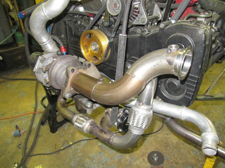
Another view of the wastegate plumbing. Getting the joints to line up took quite a bit of time.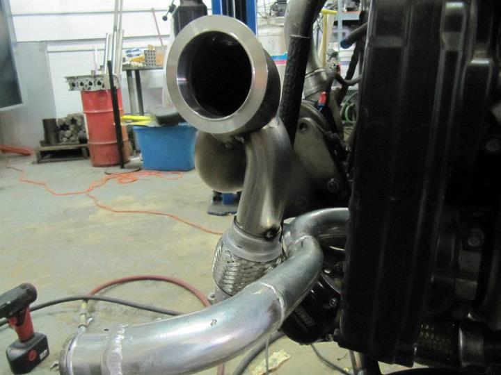
With the muffler attached.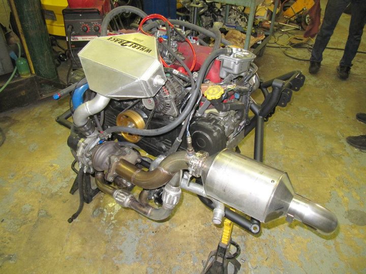
Here is the complete Sub-frame back out of the car ready for final welding, painting, and then reassembly.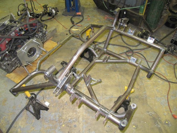
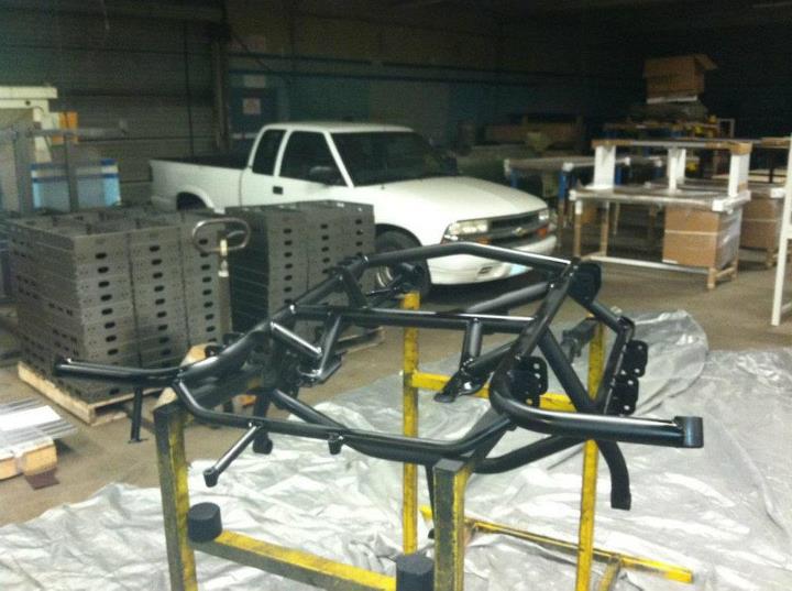
Engine and transmission reinstalled in the sub-frame.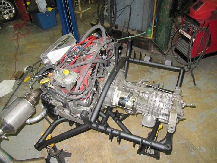
Posted by: Britain Smith Apr 4 2012, 04:36 PM
On to the interior...or cockpit I guess since there is not much interior.
Cockpit is all ready to go. Switches mounted, remote brake bias adjuster installed, dash mounted...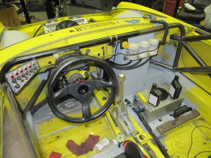
Fuel tank enclosure completed and tank/fuel pump mounted.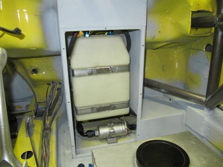
View of the fuel tank enclosure from the front.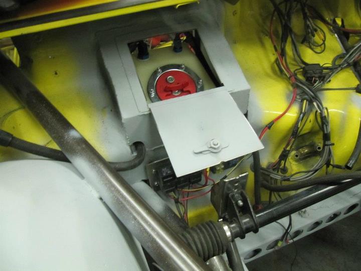
Fuel tank enclosure door closed and tank seals from inside the car completely.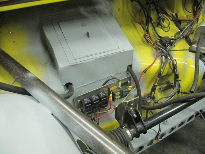
Posted by: Britain Smith Apr 4 2012, 04:42 PM
Now the exciting bits.
Got the custom set of Olhin shocks.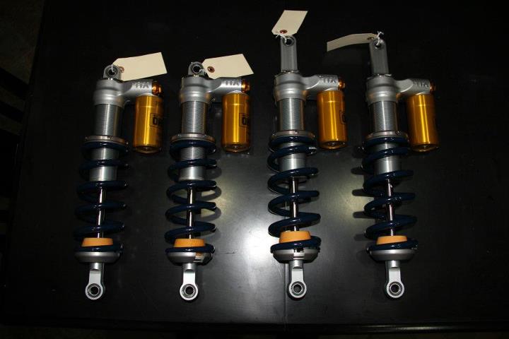
Front shocks installed on the inboard rockers. 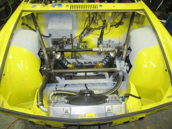
Close-up view of the front shocks installed.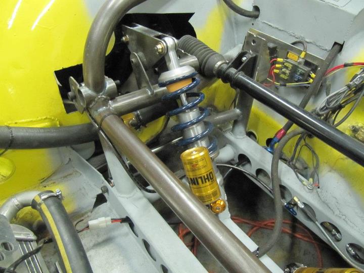
View from below of the rear shock and suspension.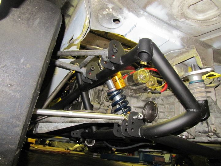
Clearance the rear trunk lid for the new cage bars. The holes are not as bad as I thought they would be.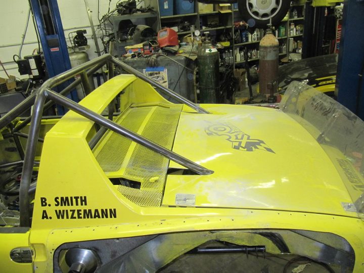
Master Welder Evan working his magic on the last few cage bars. As of now, all the major welding is completed.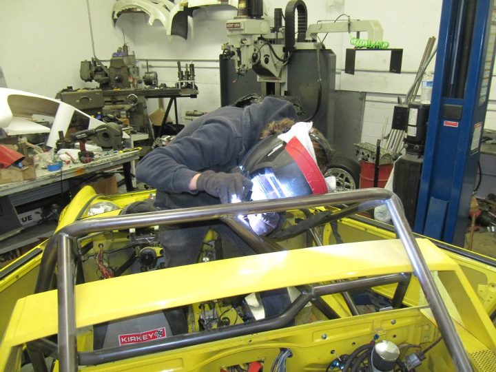
Due to the new position of the cage I had to find and modify another engine lid to clear the bars.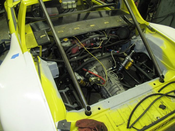
View of the modified engine lid in the up position.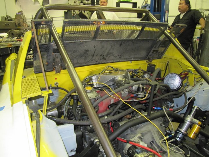
I previously mounted the vehicle speed sensor to the outside of the inboard CV, however this interfered with the springs. Therefore I had to weld it to the inside of the transmission output shaft and reverse the sensor mounting. Also added a mount for the hydraulic clutch lines.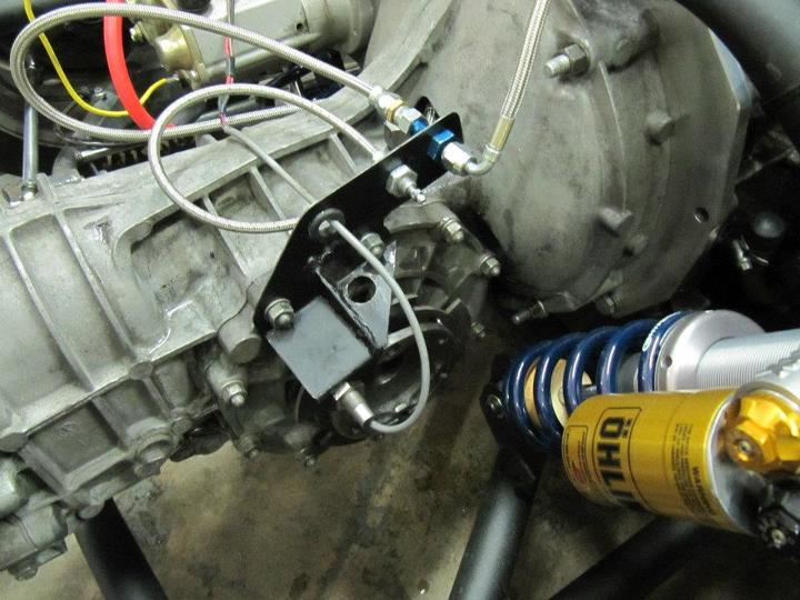
Posted by: Britain Smith Apr 4 2012, 04:44 PM
New GT Racing rear flares installed. Might need some slight modification, but at least they clear the wide wheels.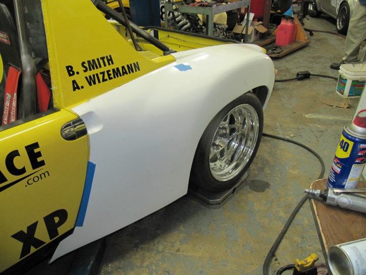
Back view of the car with the rear flares installed.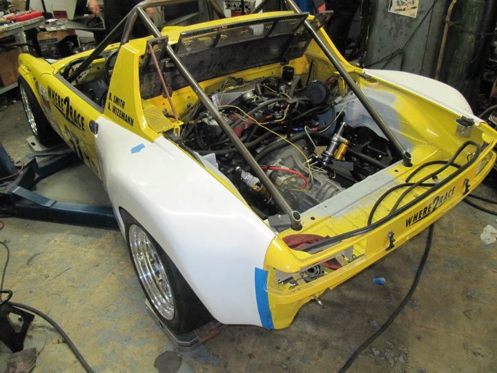
Top view of the rear fender width.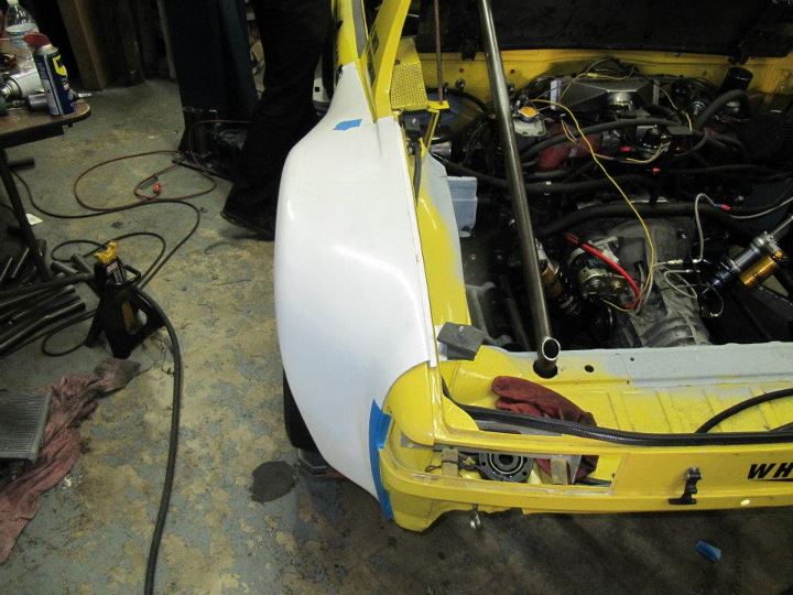
Good lower view.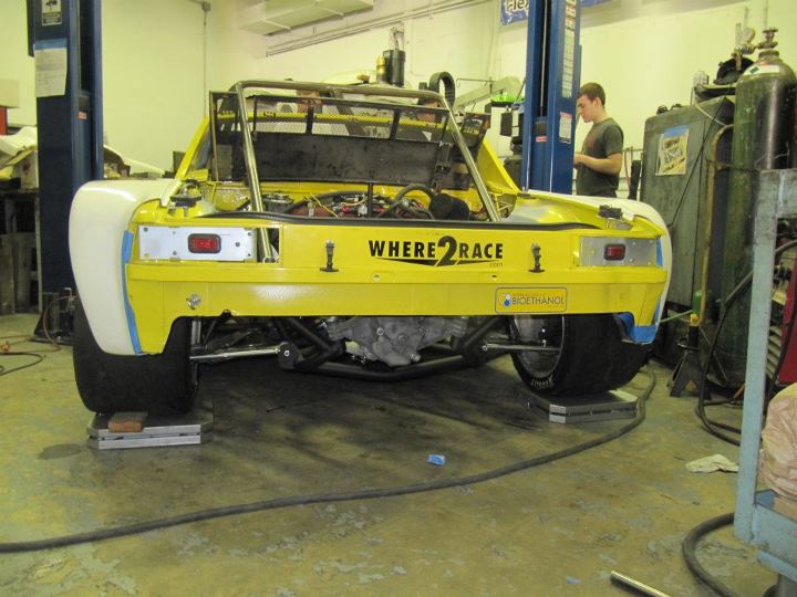
This is one of my favorite views....talk about wide!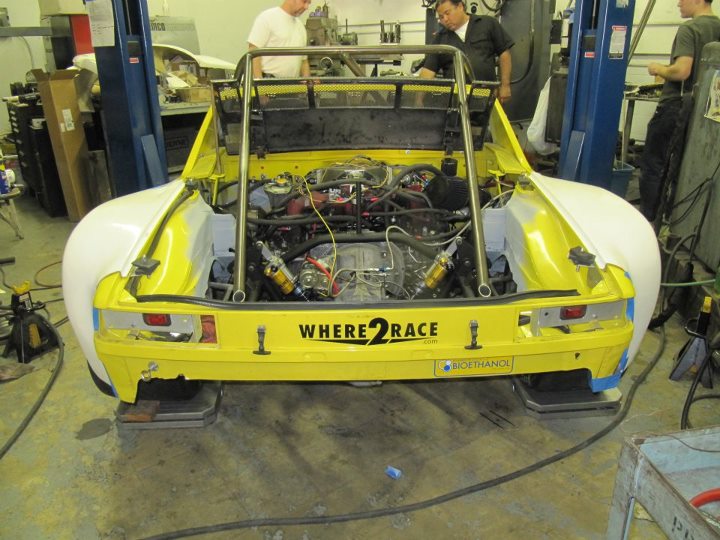
Posted by: Scott S Apr 4 2012, 05:02 PM
truely fantastic. I hope you will post track videos - cant wait to see it go.
So, are you now going to take it all apart and throw a $20k paint job on it?!!
Posted by: Britain Smith Apr 4 2012, 05:22 PM
That is a $20K paint job...
Anyway, I will paint it later this year, probably over next winter. It will take some time to get it sorts and that is a higher priority for the time being.
-Britain
Posted by: brant Apr 4 2012, 05:42 PM
what do the scales say now....
a lot of tubes on that bad boy
Posted by: Britain Smith Apr 4 2012, 05:44 PM
what do the scales say?
They say 1815lb with ballast (minimum for XP)
Let's just say that it is lighter than it was.
-Britain
Posted by: brant Apr 4 2012, 05:47 PM
what do the scales say?
They say 1815lb with ballast (minimum for XP)
Let's just say that it is lighter than it was.
-Britain
very good!
Posted by: J P Stein Apr 5 2012, 08:51 AM
Ayup, that paint can wait till the latter part of Sept. or early Oct.
You wanna get er' done before the rain/cold set in......IMO.
Till then you would just be following precedent.
Attached image(s)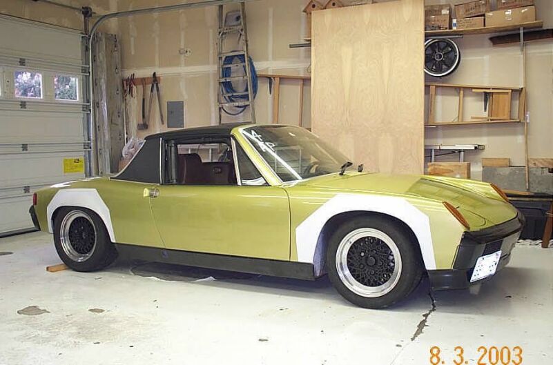
Posted by: Randal Apr 5 2012, 09:50 AM
What a machine! And great work as well.
When do you think you'll be running an event (and where)?
Posted by: Aaron Cox Apr 5 2012, 10:02 AM
holy hell that thing is wide! that should be an absolute monster!
Looks great. And to think it started off as a 914 
Posted by: Borderline Apr 5 2012, 10:14 AM
Those flairs look great!! That view from the back will look even better when the rear deck lid is in place!! Don't let them wide tiars knock over any cones. It must be hard to remember they're out there!
Posted by: Britain Smith Apr 5 2012, 10:19 AM
Thanks guys.
It is really not that much wider than it was with the old set-up...maybe 1.5inch per side. The flares just make the butt look big
-Britain
Posted by: sixnotfour Apr 5 2012, 10:24 AM
I thouht they were data aquistion stations for your lap top.
Posted by: Heater Guy Apr 5 2012, 11:04 AM
Hi Britain,
Your project looks fantastic! But, where are you going to put the intercooler? You may not need a muffler. I have a short pipe from the turbo and the most I have registered is 95 db on the track.
I finally got the Subaru 5 speed installed and track tested. It works fantastic. Now I hope it will hold up.
When are you coming to Norcal?
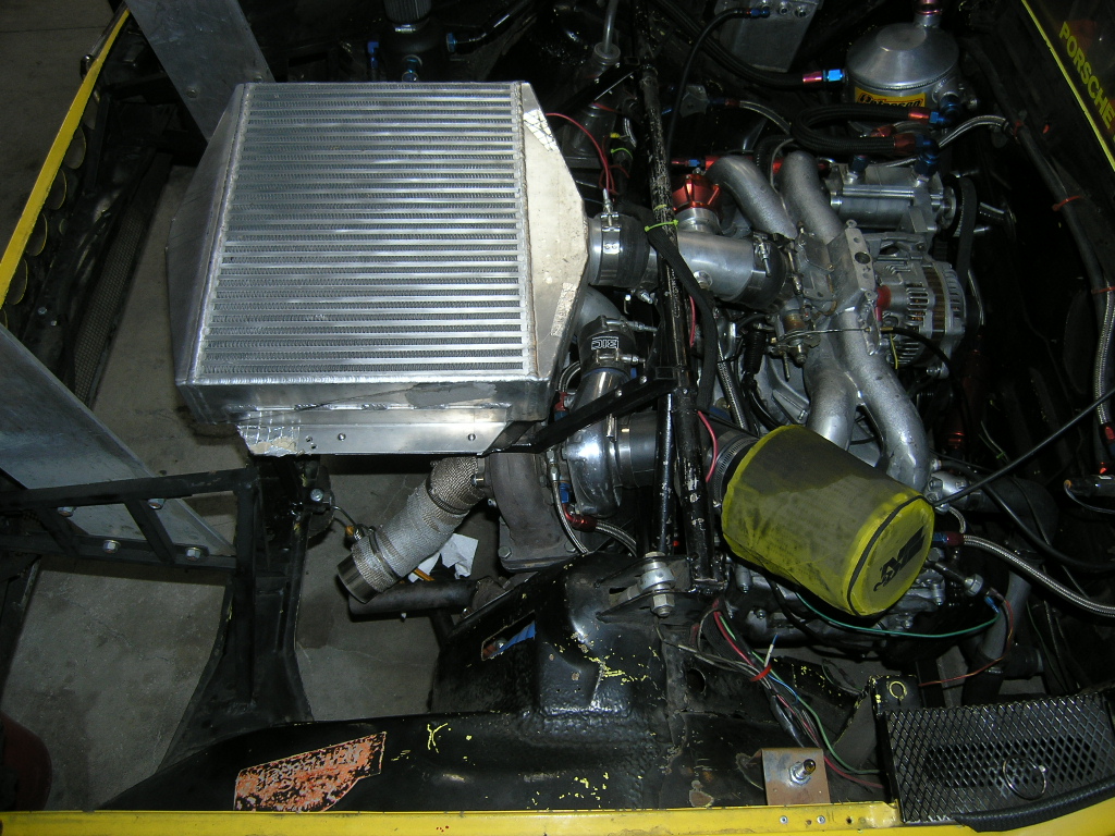 [attachmentid=306990] [attachmentid=306990]
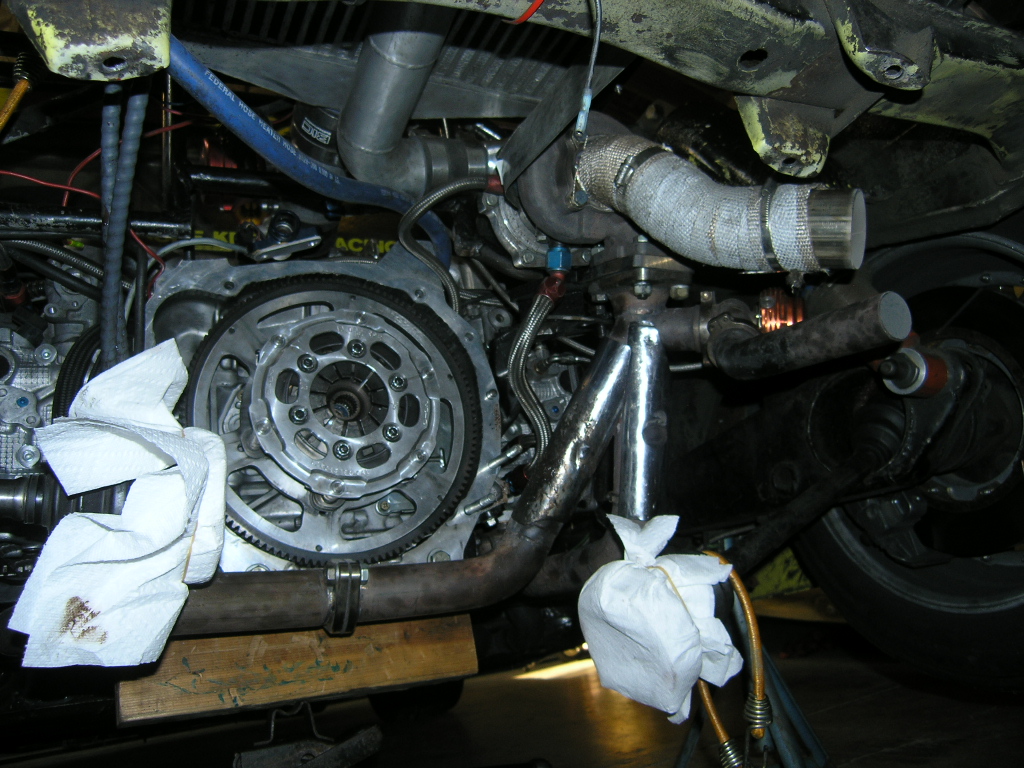
Posted by: Britain Smith Apr 5 2012, 11:12 AM
I run an Air/Water intercooler right on top of the motor....very efficient.
As for the muffler, I need to ensure that I hit 93db at 50ft in San Diego. Remember, my motor spins to 8500rpm and is a bit louder than the US Spec engines.
-Britain
Posted by: J P Stein Apr 5 2012, 11:13 AM
Oh never mind
Posted by: shuie Apr 5 2012, 12:00 PM
Are the bearing carriers from a Lotus? Did you ever look at C5 suspension parts for this project? I've been daydreaming about an LS conversion with a C5 based pushrod suspension for the last few months and had not seen these updates. The pictures of the subframes on your car are really helpful
Posted by: shuie Apr 6 2012, 09:05 AM
Just had a chance to go back through the thread on my computer instead of the phone. This is very nice work
Britain, would you be willing to share about what the track width will be with those wheels & tires? Or, even the hub-to-hub width if that's easier to guess or measure. Did you try to use all of the Lotus dimensions?
TIA for any info.
Posted by: J P Stein Apr 6 2012, 09:29 AM
IIRC, the cone guts used to start about 1/3rd of the way along the then new HPH fenders. They were "not that much wider" also.
Posted by: Britain Smith Apr 16 2012, 12:26 PM
She is alive!
I didn't get to drive it yet, but the car successfully made it through a set of shake down runs at El Toro this past weekend. Still needs proper bodywork, ride height lowered, sway bar, new tires, proper brake pads, cage painted, replacement ball joint, and some spring changes...but it is getting closer.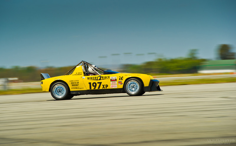
-Britain
Posted by: ChrisNPDrider Apr 16 2012, 09:41 PM
Posted by: DanT Apr 16 2012, 09:50 PM
Brit,
Since the motor is a Porsche licensed design, you should be able to class it and run for points if you want to come to some GGR events!
Some fantastic fab work, hope the sorting goes quickly and smoothly for you!
Posted by: Krieger Apr 16 2012, 09:54 PM
Absolutely amazing work! Have fun driving it.
Posted by: ChrisNPDrider Apr 17 2012, 09:48 AM
Brit,
Since the motor is a Porsche licensed design, you should be able to class it and run for points if you want to come to some GGR events!

Posted by: Chris Hamilton Apr 17 2012, 02:02 PM
Looks like fun!
What are you planning on for your final ride height?
Posted by: Britain Smith Apr 17 2012, 02:23 PM
Similar to what it was last year...which is quite a bit lower than the picture.
-Britain
Posted by: Randal Apr 17 2012, 02:53 PM
Similar to what it was last year...which is quite a bit lower than the picture.
-Britain
You mean SLAMMED?
You could run a bunch lower than the Porsche suspension would allow, right?
Congratulations on getting the car out.
Posted by: Britain Smith May 18 2012, 01:08 PM
It has been a few weeks since I last posted, but in that time we have ran the car at the San Diego National Tour and the El Toro Pro Solo. Both weekend were not without issues, but we are getting much closer to completion.
I will start out with the San Diego National Tour weekend. I arrive a day early to get everything sorted out on the car and ensure that it was ready. We spent quite a bit of time on the small stuff, including several hours to get the car corner weighed and aligned. There are just so many adjustments that it takes a while to get them all working together.
Once we had everything completed, it was time to test drive it up and down the street in front of the shop and get it loaded up. Just as we were about to load it in the trailer, the transmission decided to grenade and no longer function. We pushed it into the shop and were able to pull out the transmission, rebuild it, and reinstalled in 1hr and 9mins....it ended up just snapping the arms off the slider hub and we upgraded to a later model 915 slider which is much thicker.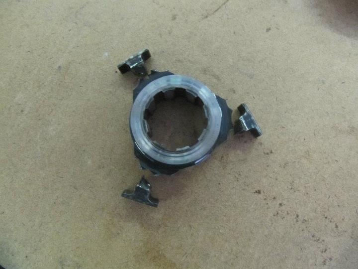
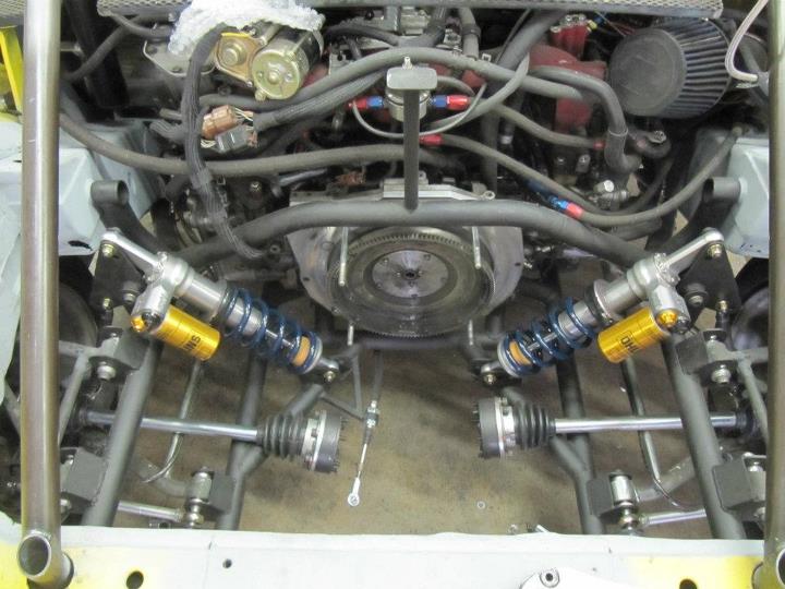
With that fixed, we headed to San Diego.
Since the shake down runs, we added a front blade adjustable sway bar, lower the spring rates, upgraded to racing brake pads, and put on the new tires. It was basically a new car at this point. We basically spent the entire event making set-up adjustments and reteaching our brain how to drive this think. It is odd to get into a car that you have been driving for so long and to break all those habits that it took to make the previous set-up work.
Here are some pictures of the car in San Diego. The ride height is about 2.5inchs higher than optimal because the front wheels would hit the fender thru the turning arch. The set-up that I went with is QRS Fiberglass front fenders widened about 1.5" and GT-Racing Rear Fenders. 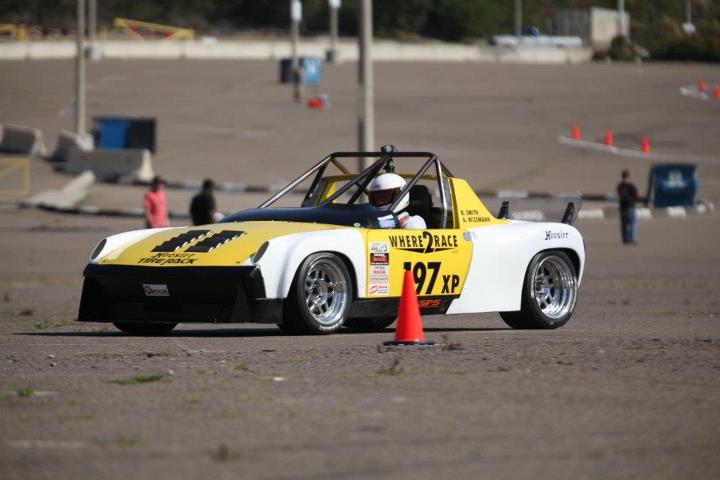
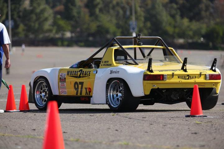
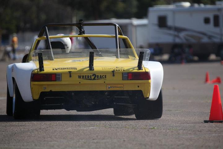
The next weekend I returned to So-Cal to run the El Toro Pro Solo. This time around we had time to cut the front fenders for more tire clearance and lower the car to the desired height.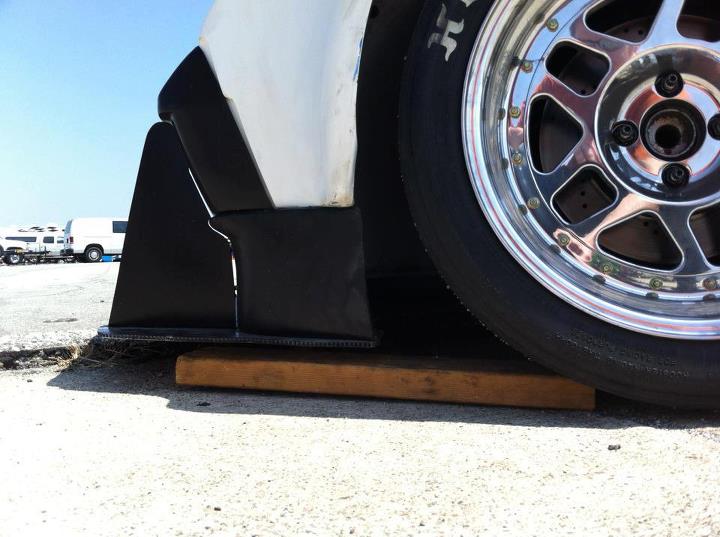
Unforeseen issues with this new ride height was that the front lower control arm was hitting the sway bar bracket under bump and therefore resulted in the car having basically "infinite" front spring rate. This explained the bad corner entry push and corner exit snap-oversteer that occurred the first day of the event. We returned to the shop to relocate the front sway bar to a higher location to gain the necessary clearance.
The car showed much improvement while running the next day. However, now under hard breaking on corner entry we had the splitter hitting the ground and the wheels rubbing the inside upper fender well due to the car sitting too low. This really cause the car to get upset on low-speed corner entry and greatly effected my run times.
I have since raised the front end, reset the bump steer, set the toe and I am ready to go racing again this weekend for further development time.
I will get some more pictures posted soon, I have spent most of my time underneath the car with dirty hands.
-Britain
Posted by: JRust May 18 2012, 01:21 PM
Making great progress Brittain! Congrats & keep up the fight. You'll have it all dialed in soon enough. Can't wait to see you run that beast once it is
Posted by: Brett W May 19 2012, 08:56 AM
How tall are you? What was the reasoning behind the super tall cage?
Car is looking good. Can't wait to see it in action.
Posted by: sean_v8_914 May 19 2012, 09:13 AM
this project is an epic achievement, congratulations
Posted by: Britain Smith Jun 18 2012, 04:26 PM
Small updates to the car as we continue to get it sorted out.
First up, transmission refresh. When we were in there replacing the busted slider hub a while back, I had noticed a small crack forming in the cage of the large roller bearing in the intermediate plate. We didn't have a spare on hand at the time so I had to go back and replace this part. I am glad I did as the crack had grown and who knows how much longer it would have stayed together.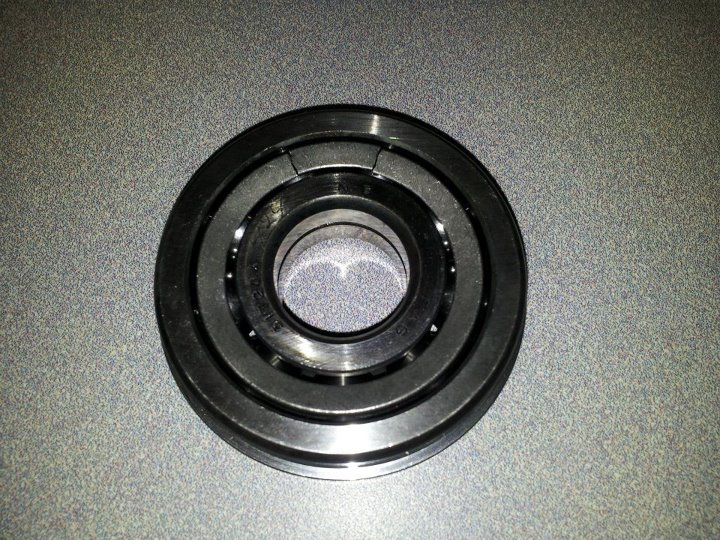
Next on the list of "upgrades" was to get rid of the 40+ year old Porsche steering column. Combination of flex in the column mounts as well as a worn out inner bearing was causing noticeable movement of the steering wheel under load. My plan was to install a steering quickener to serve as the new steering column.
Here is the Porsche steering column: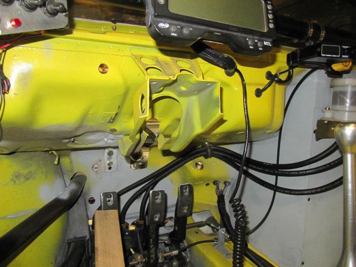
My first attempt at this employed a 2-bolt steering quickener with an extension shaft machined and a plate with the Mom hub pattern waterjet cut. Here is a comparison of the Porsche steering column next to the Steering Quickener piece. 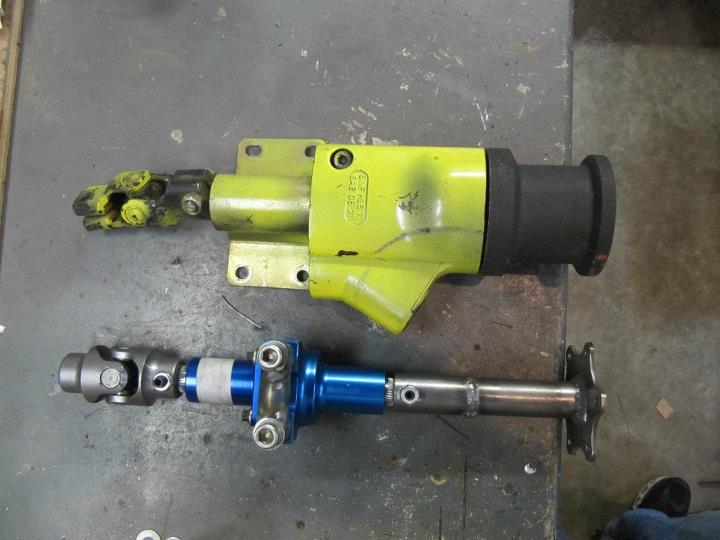
Here is the set-up installed.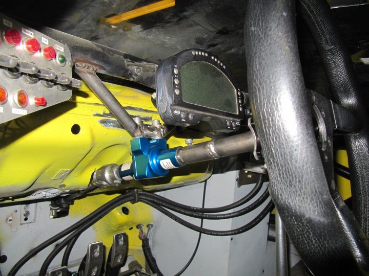
While it did greatly increase the steering response, basically 1 turn either way to hit lock, it didn't improve the lateral movement of the steering wheel. After a bit of research, I found that Coleman actually makes a 3-bolt version that is actually intended to be a steering column type piece.
Here it is installed with additional bracing.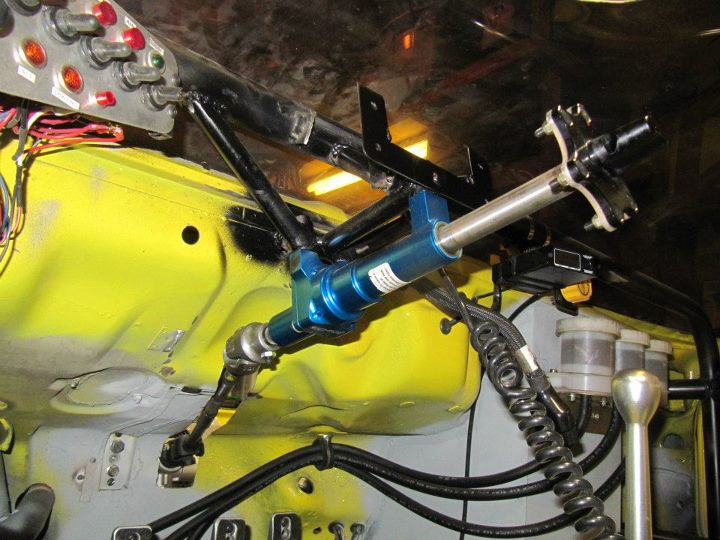
Much better feel and a whole lot less lateral movement. We also extended the wheel out closer to the driver by about 1" to improve the drivers leverage on the wheel.
Here is the cockpit back together. 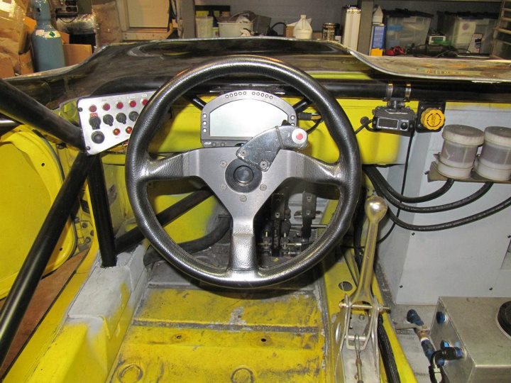
-Britain
Posted by: Britain Smith Jun 18 2012, 04:33 PM
The other major update was a new clutch/flywheel package. I was previously running a Tilton single disc set-up and was right up against the load rating for the set-up and therefore wearing out clamping plates and friction discs very quickly. In addition, the Tilton parts were getting harded and harded to find as they stopped making a lot of components.
The new set-up consists of another custom machined flywheel and a Sachs dual plate set-up. This unit is rated at 600ft-lbs and should be plenty strong enough to handle my measly power
Here is the old set-up next to the new one: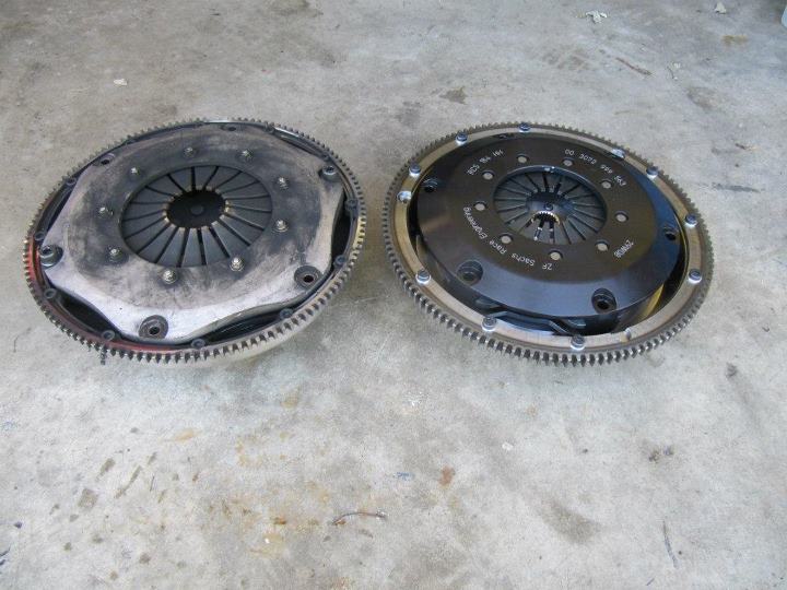
Here is the new flywheel and clutch package, the flywheel is a piece of art...and cost about the same. 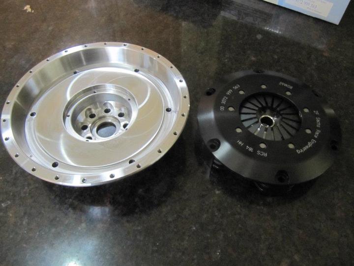
The flywheel is unique in that it has a center plate that is installed over the flywheel bolts to capture the nose of the transmission mainshaft.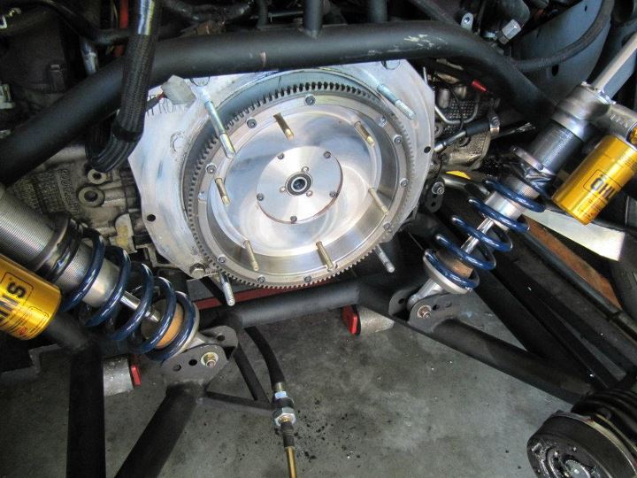
Installed and all torqued down: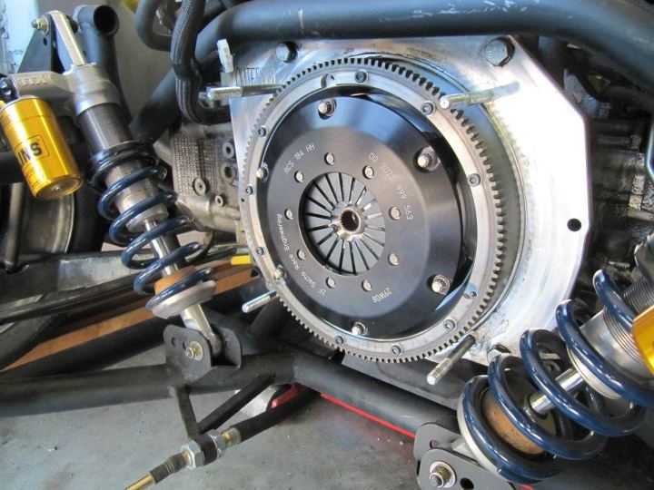
Everything back together, clutch bled, ready to do burnouts.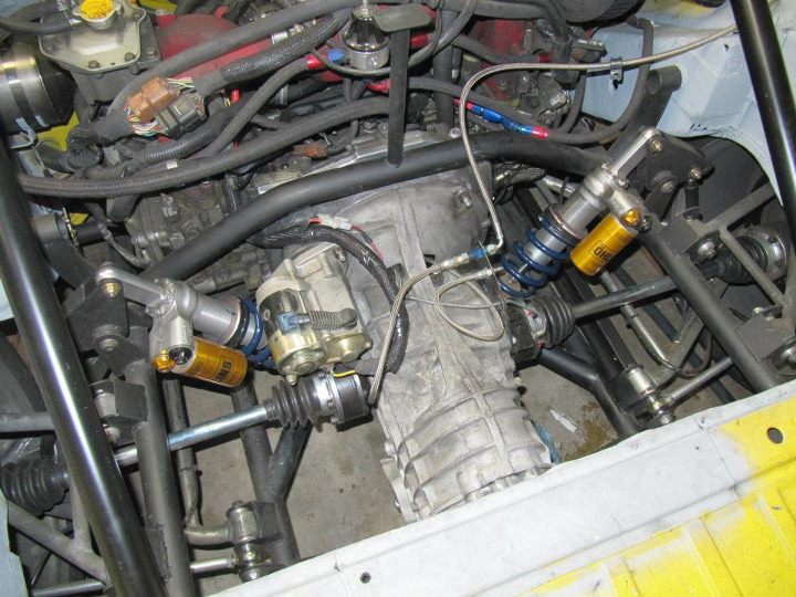
We ran the car this past weekend and the new clutch has a great feel and works great!
-Britain
Posted by: yeahmag Jun 18 2012, 04:46 PM
Are you running a 1.5 or a 2:1? I've been threatening to do this for years...
Posted by: Britain Smith Jun 18 2012, 04:48 PM
Are you running a 1.5 or a 2:1? I've been threatening to do this for years...
It is a 1.5:1. A 2:1 would be crazy. I love it!
-Britain
Posted by: grantsfo Jun 22 2012, 12:26 PM
Now all thats left for you to replace is that old worn out 45 year old chassis. LOL!
So you going to take a chance and go to Nationals this year? Seems like youre running a little late if you are going to make a serious run. Of course non serious runs are fun too! Bet you could break into top 10 with it as it sits now.
Posted by: z31turbo Jul 24 2012, 08:48 PM
Looks great, keep up the good work!
JF
Posted by: Britain Smith Aug 31 2012, 12:02 AM
I know it has been a while since I have updated this thread...but it has been a long, great summer of racing. The car is running great and the new suspension is phenomenal.
Couple of updates. First off, bump steer! After everything was built and the car was up on the alignment rack I determined that I had made a small mistake in my calculations and induced a bit of bump steer that I was unable to account for in the adjustment range that I incorporated. This was partly due to the changes in the suspension geometry as compared to a stock Lotus.
Anyway, the remedy was to convert the stock Lotus tie-rod ends to heim-joints. I located a kit from a company in the UK and decided to use that as a starting point. After a little bit of modifications to the supplied kit, we got to the end result which is zero bump! Here is a picture of it installed.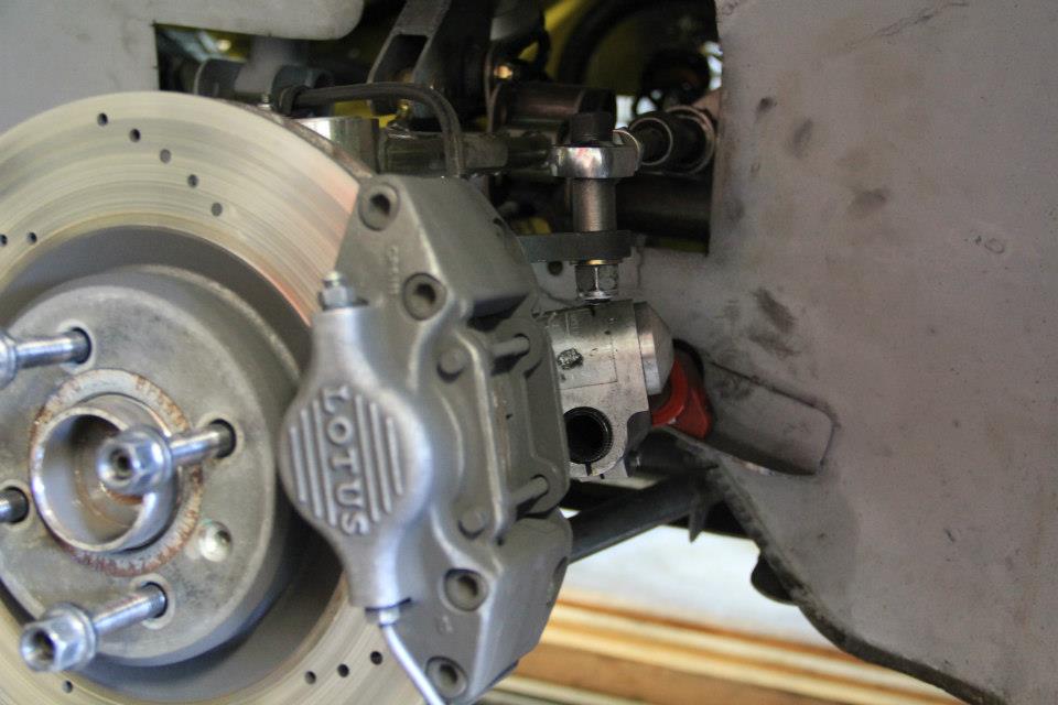
Secondly, I installed a simple launch control set-up on the car to allow faster Pro-Solo type launches and to put less slip on the new clutch set-up. Here is a cool video of the system in action...plus 100ft burn-out are cool no matter who you are.
http://youtu.be/pB0fTcTHkg4?hd=1
Finally, here is a cool video that I put together at a recent event where they allowed me to run without the front and rear hoods to get a good shot of the suspension in action. Let me tell you, the car was nearly impossible to drive without the rear hood on and the lack of a rear spoiler.
http://youtu.be/A3C1Re--oTw?hd=1
Enjoy,
Britain
Posted by: DBCooper Aug 31 2012, 04:36 PM
Wow, looks fast and stable. How are you doing vs. competition? Are you getting the results you'd hoped for? I'd assume you're still getting used to the car since everything in it is new or different.
What I'm most curious about is what you think of the turbo motor. No question they have all the horsepower, but are you able to control it? Sometimes all that power coming in surprises me, and I wonder if it upsets your balance in driving, if you've managed to adapt, if it's a factor at all.
Posted by: Britain Smith Aug 31 2012, 05:23 PM
Hey DB,
The JDM Spec-C motor has very little turbo lag due to the twin-scroll and relatively small turbo. It is not as difficult to drive as some people seem to believe. You definitely have to drive it a little differently to stay in the boost, but it doesn't take long to get the feel of it.
Regarding the suspension...it is awesome. The car drives like a modern car and responds very well to adjustments.
The season has been interesting...as I get more familiar to the car, the tires are getting older. I had over 130+ runs on them and the car was still performing well. I just switched over to a new set of Goodyears so we will see how those work.
-Britain
Posted by: dian Sep 11 2012, 02:06 AM
i just read the whole thread. thanks for sharing. my question regards the engine. you mention jdm version8 spec c. what exactly is that, as jdm seems to be selling stock used engines. and what turbo are you using? it is an exellent mach for the motor.
Posted by: FourBlades Sep 11 2012, 06:41 AM
This is one of the all time 914 World threads...
Stuff I never knew was even possible made to look easy and fast to accomplish, but I am sure not cheap.
John
Posted by: Britain Smith Sep 11 2012, 11:16 AM
i just read the whole thread. thanks for sharing. my question regards the engine. you mention jdm version8 spec c. what exactly is that, as jdm seems to be selling stock used engines. and what turbo are you using? it is an exellent mach for the motor.
The JDM Spec-C engine was a limited production engine produced for the Japanese market. It was a 2.0L with various internal upgrades like counterweight/nitrided crank, large port heads, different pistion, twin-scroll turbo, no emission, etc. There were different versions over the years with version 8 being the one that I got. Because of the limited production (i.e. ~900/year) and the fact that it had little emissions other than a cat, owners in Japan are required to change the engine after 5 years and therefore there is a surplus of these engines that are then imported into Canada and sold to people in the US.
That is how I understand it.
-Britain
Posted by: Britain Smith Sep 11 2012, 11:18 AM
This is one of the all time 914 World threads...
Stuff I never knew was even possible made to look easy and fast to accomplish, but I am sure not cheap.
John
Thanks! I will tell you one thing, I would argue that it is the best handling 914's out there.
-Britain
Posted by: Britain Smith Oct 8 2012, 12:58 PM
Hey Guys, the Where2Race Motorsports Porsche 914 ran the 2012 Siskiyou Club Fall Enduro this past weekend, taking TTOD and setting the XP class track record at 3:42.007secs (beating the previous XP record by 10secs). I was less than 3secs off the overall track record set by an A-mod and with a little aero improvement and some more aggressive driving I think I could have gotten it.
Here is a video of my run.
http://www.youtube.com/watch?v=Iy2kCsOYFyc&hd=1
With only one shot at the course, you can't afford any mistakes so I ended up driving a little conservative as you can see with my early braking points. You also go out "cold turkey" so that first lap is challenging as the tires and the brakes get up to temp. Either way, it is a great event and can't wait to give it another try next year.
-Britain
Posted by: Woody Oct 8 2012, 01:49 PM
That looks like a bunch of fun. Real tight track, is it a cart track?
Posted by: Britain Smith Oct 8 2012, 01:57 PM
Go-Kart Track.
http://www.where2race.com/venues/view/medford-kart-track
Posted by: FourBlades Oct 8 2012, 05:52 PM
Congrats on the new track record!
You have some real driver skills, looks bumpy and challenging.
John
Posted by: Britain Smith Oct 8 2012, 11:48 PM
Congrats on the new track record!
You have some real driver skills, looks bumpy and challenging.
John
Thanks man.
It is actually not as bumpy as it looks....however it is challenging to get it right for 5 laps in a row. My last two laps were my fastest ever around that track.
-Britain
Posted by: DBCooper Oct 9 2012, 10:37 AM
Very cool Brit, congrats. My son set the record in Street Prepared at that same track eight or ten years ago, a VW Ghia with a 2.0 T4 motor. I remember everyone liked the track, different than most autocross venues. Looks like fun.
Posted by: Phil Plummer Nov 4 2012, 07:53 PM
Very very nice! I can only wish I had the skills to do what you've just accomplished!
Once done..your going to kick some A with that set up:)
Congrats and good luck!
Hi: can anyone tell me where I can find a well priced oil cooler for my 914/6 conversion??? the front bumper is a 916 type. I need an oil cooler that fits well.-Phil
Posted by: Elliot Cannon Nov 5 2012, 09:29 AM
Very very nice! I can only wish I had the skills to do what you've just accomplished!
Once done..your going to kick some A with that set up:)
Congrats and good luck!
Hi: can anyone tell me where I can find a well priced oil cooler for my 914/6 conversion??? the front bumper is a 916 type. I need an oil cooler that fits well.-Phil
Send a PM to bdstone.
Posted by: Britain Smith Nov 5 2012, 10:14 AM
Very very nice! I can only wish I had the skills to do what you've just accomplished!
Once done..your going to kick some A with that set up:)
Congrats and good luck!
Hi: can anyone tell me where I can find a well priced oil cooler for my 914/6 conversion??? the front bumper is a 916 type. I need an oil cooler that fits well.-Phil
Interesting Hijack!
Posted by: FourBlades Nov 5 2012, 12:19 PM
Dang! I was hoping there would be some more good stuff on your car!
Is the season over for you?
John
Posted by: Britain Smith Nov 5 2012, 12:27 PM
Yep...season is over. I have some things planned for the offseason...stay tuned.
-Britain
Posted by: Britain Smith Feb 14 2013, 04:37 PM
Couple of updates of what I have been working on. There is going to be a nice addition going on next week and I will post those pictures then.
First, I decided to strip the multiple years of undercoating, grims, etc. out of the fender wells. A quick coat of primer and they look much better.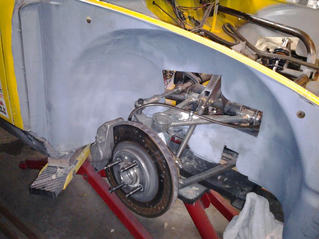
Rear fender well stripped and primed. Gotta add another fender support that will go out horizontally just before the wheel opening. I hit a few cones this last season and actually cracked both rear fenders.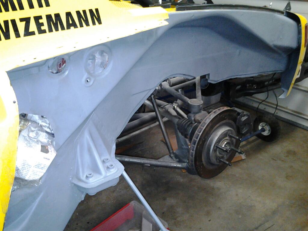
hated the duez fasteners that were holding the front hood on so today I replaced the outside four with Aerocatches. I had to redo all the mounting brackets and cut holes in my carbon hood, but overall weren't too bad to install. They are very nice parts, pricey, but nice.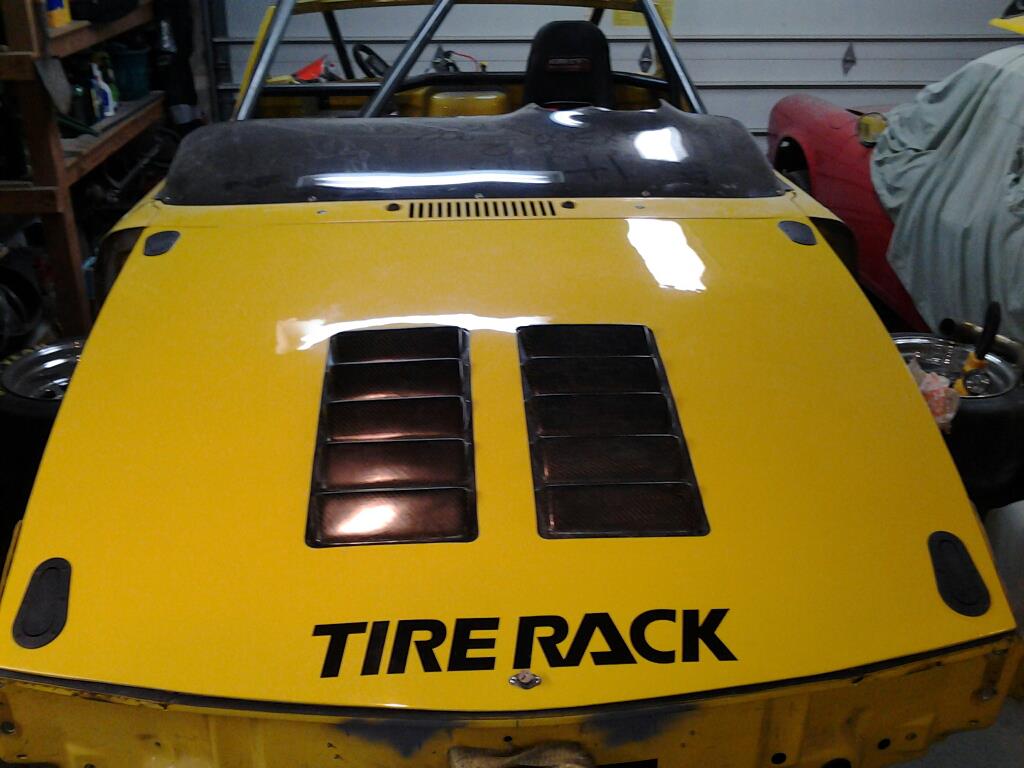
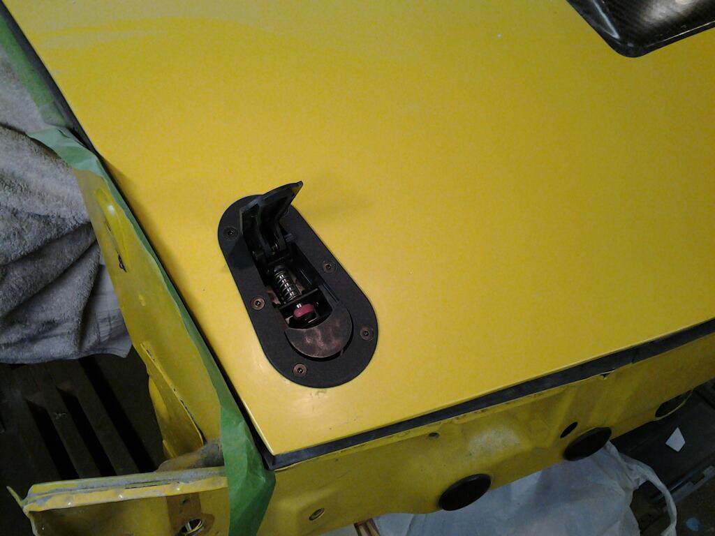
Aerocatches on the front bumper. I will fill the old DZUS holes and clean all that up. 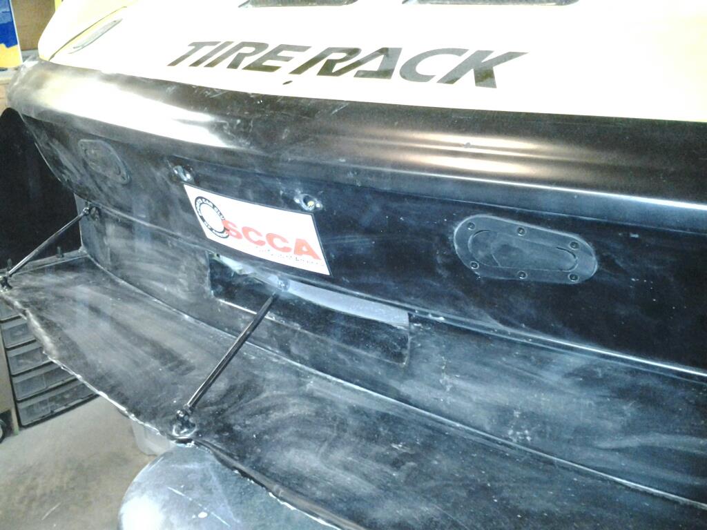
Front fenders freshly painted and mounted. I also cleaned up and spray painted the inner fender wells to match. It is much cleaner and brighter in there now.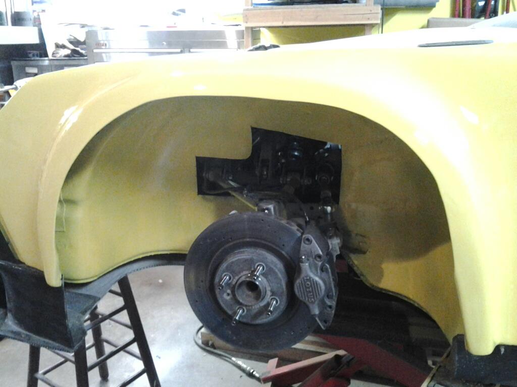
Front view of freshly painted fenders mounted, aerocatches in the hood and front bumper. Need to replace the splitter, I have to source a new supplier for Alumacore or Alumalite.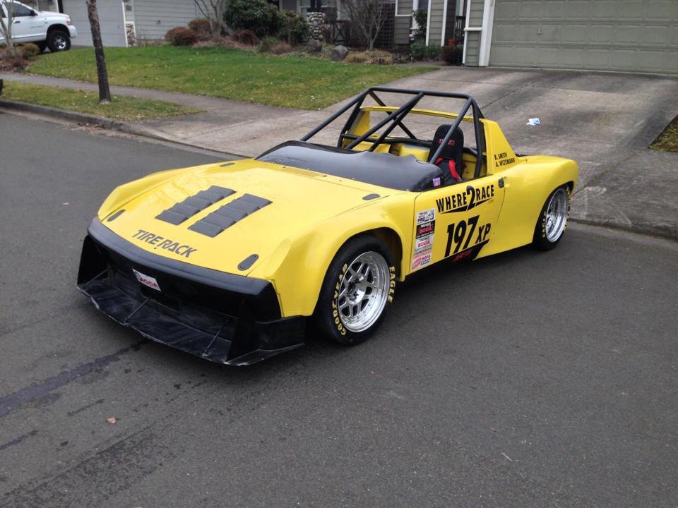
Degreased and powerwashed the engine today. The JDM intake manifold looks so much better with the engine clean.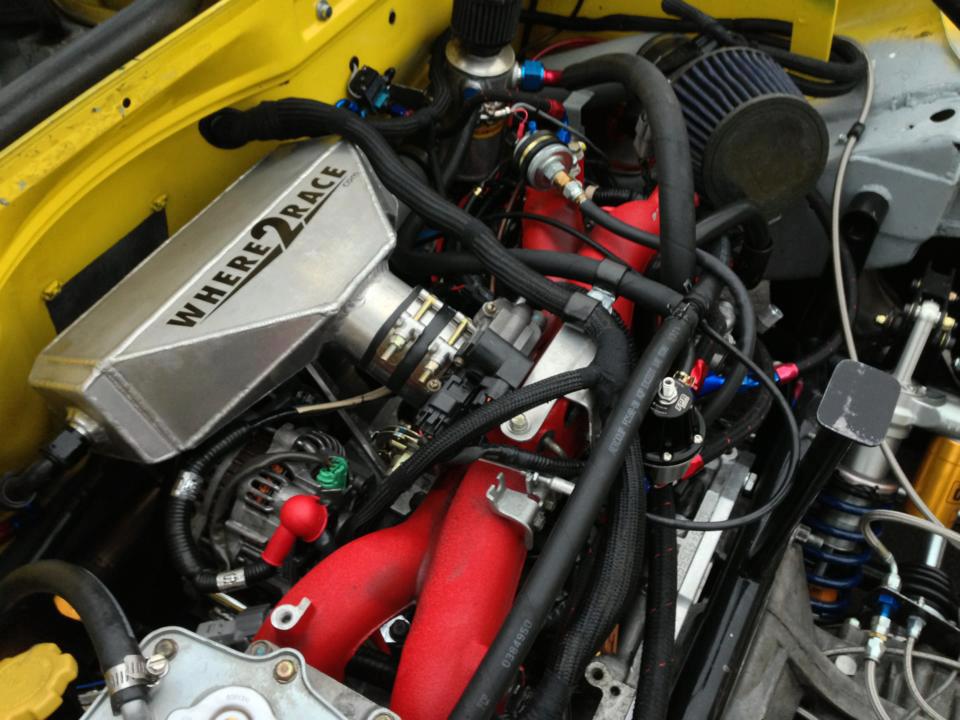
That is a lot of yellow. The car is all cleaned up and ready to hit the dyno next week for a retune.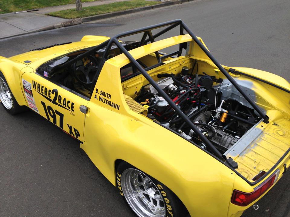
-Britain
Posted by: tscrihfield Feb 14 2013, 07:23 PM
Looks awesome! I really like your attention to detail!
Thomas
Posted by: Britain Smith Feb 19 2013, 11:12 PM
Well, if I can't make it go faster, I might as well make it pretty. Painted the cage in the front and sprayed some yellow on sheetmetal.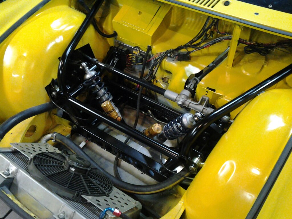
Then...Murphy's Law strikes again!! Getting the car ready for a dyno session on Thursday so I took a few laps around the block only to find oil squirting off the back of the motor. See the hairline crack just above the banjo fitting. This is the AVSC line on my engine.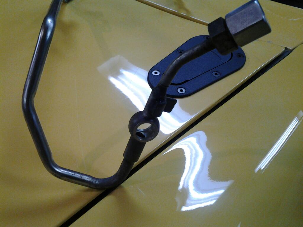
Posted by: Britain Smith Feb 20 2013, 11:51 AM
Oil line tig welded shut this morning, now to reinstall tonight and re-bleed the radiator.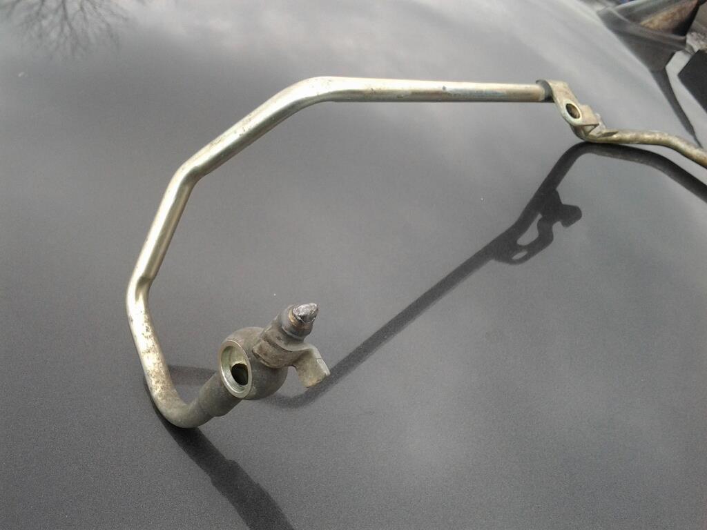
Posted by: Britain Smith Feb 22 2013, 12:57 PM
Took the car down to Cobb Tuning Surgeline for Dr. Tim Bailey to work his magic on tuning the car for the new injectors and more boost. Overall the session went great with the engine running well and no major issues.
Here is the car strapped down to the dyno.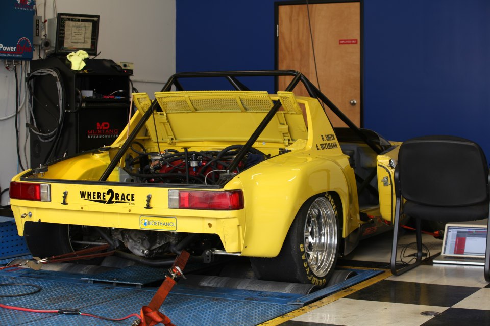
I had to take off the driver side rear fender in order to get an A/F meter on the exhaust which exits out under the car. 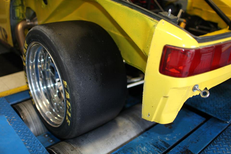
At higher power levels we were dealing with significant rear wheel spin. We ended up with 3 jugs of water in the rear truck to put weight over the rear wheels.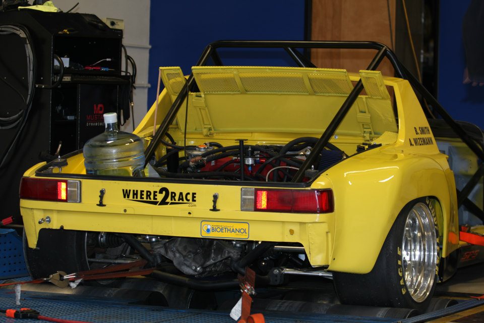
Here are the final dyno plots. At 18psi, we are making 335whp and 305ft-lbs. This is on a Mustang Dyno which notoriously measures low. Either way, the hp is fairly linear all the way up, we reach full boost pretty quickly, and the torque curve is nice and flat where we want it.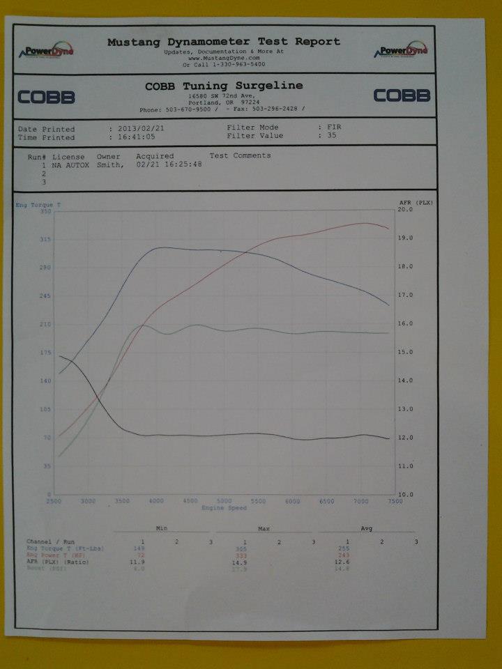
I am working on video and will post it soon.
-Britain
Posted by: championgt1 Feb 22 2013, 01:40 PM
335 whp! Not sure if you mentioned it before. How much does the car weigh?
Posted by: Britain Smith Feb 22 2013, 02:01 PM
1825lbs
Posted by: RobW Feb 22 2013, 02:19 PM
TTOD 2013 Porsche Parade?
Nice job Brit!
Posted by: ChrisNPDrider Feb 22 2013, 02:20 PM
Nice job on the prodigious use of yellow paint
When do we see the 25 psi boost dyno run?
Posted by: Britain Smith Feb 22 2013, 03:09 PM
TTOD 2013 Porsche Parade?
Nice job Brit!
I wish...in the eyes of PCA this is not a real Porsche...on so many levels.
-Britain
Posted by: Britain Smith Feb 22 2013, 04:23 PM
Ok, here is the video from the dyno runs yesterday.
http://youtu.be/dj-BXAbsVoE
Posted by: championgt1 Feb 22 2013, 04:31 PM
1825lbs
Damn!!
Posted by: BKLA Feb 22 2013, 06:20 PM
Holy  !!!
!!!
Need to come and see before it goes to Cali....
Posted by: Britain Smith Mar 20 2013, 12:15 PM
Sorry for the delay in updates. I have been really busy working on the car and completing a bunch of aero upgrades. We ran this car this past weekend and were very happy with the results.
First off, we got a new piece of Alumlite for the front splitter. The last one got banged up pretty good. 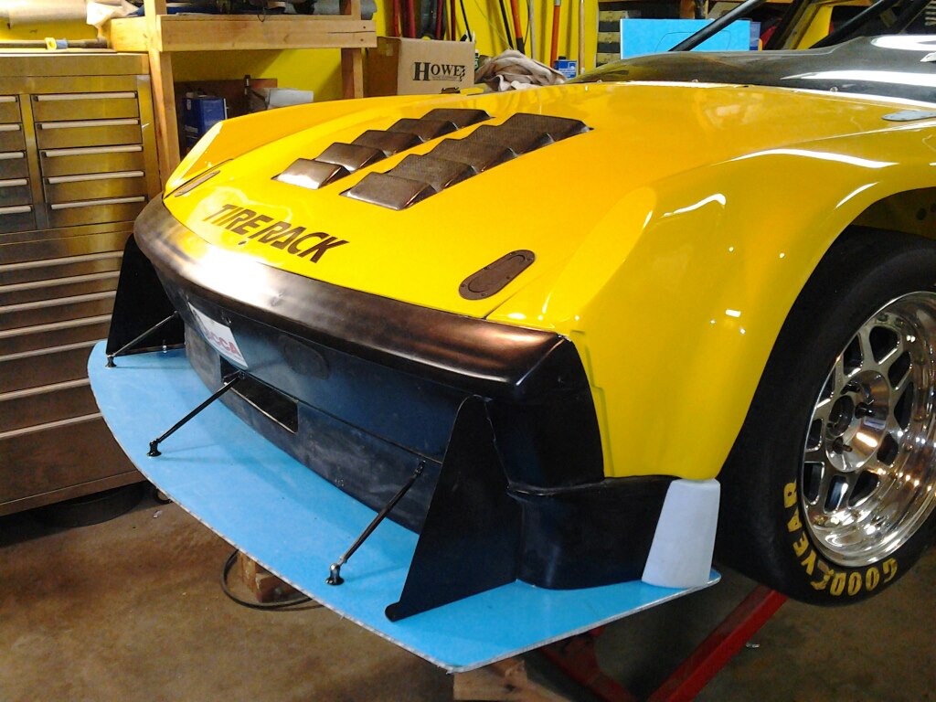
Looking underneath, the splitter goes back as far as allowed.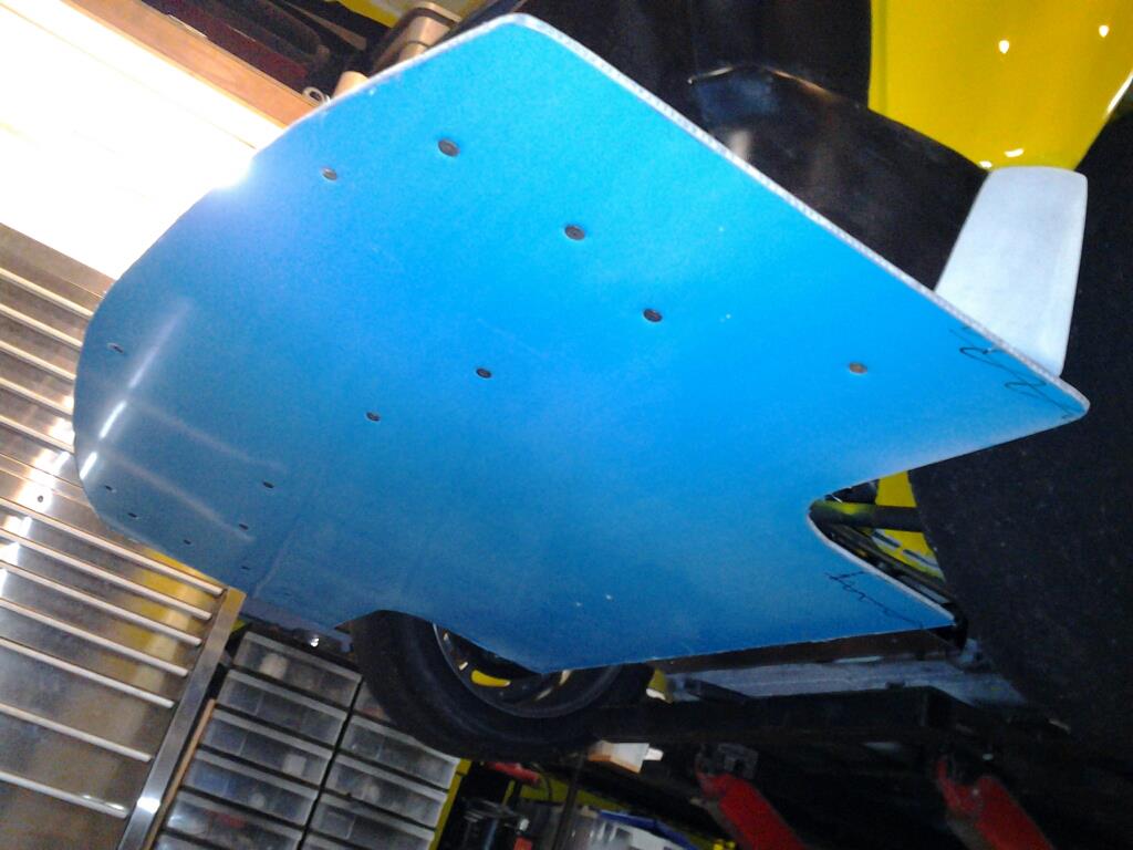
The front of the splitter was wrapped in a layer of fiberglass and carbon fiber to protect the leading edge. This thing took multiple cone hits this past weekend without even a scratch.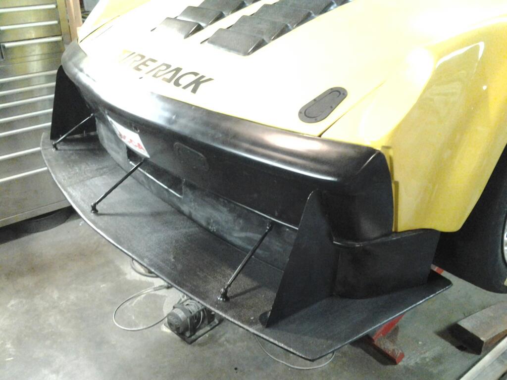
Also modified the front valance that to match the front fender profile.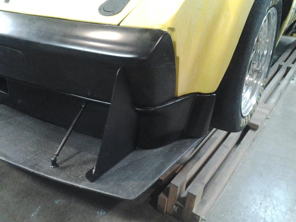
Posted by: Britain Smith Mar 20 2013, 12:42 PM
The next step down the path of aero upgrades was the rear.
Here is the rear trunk lid with the lexan spoiler removed.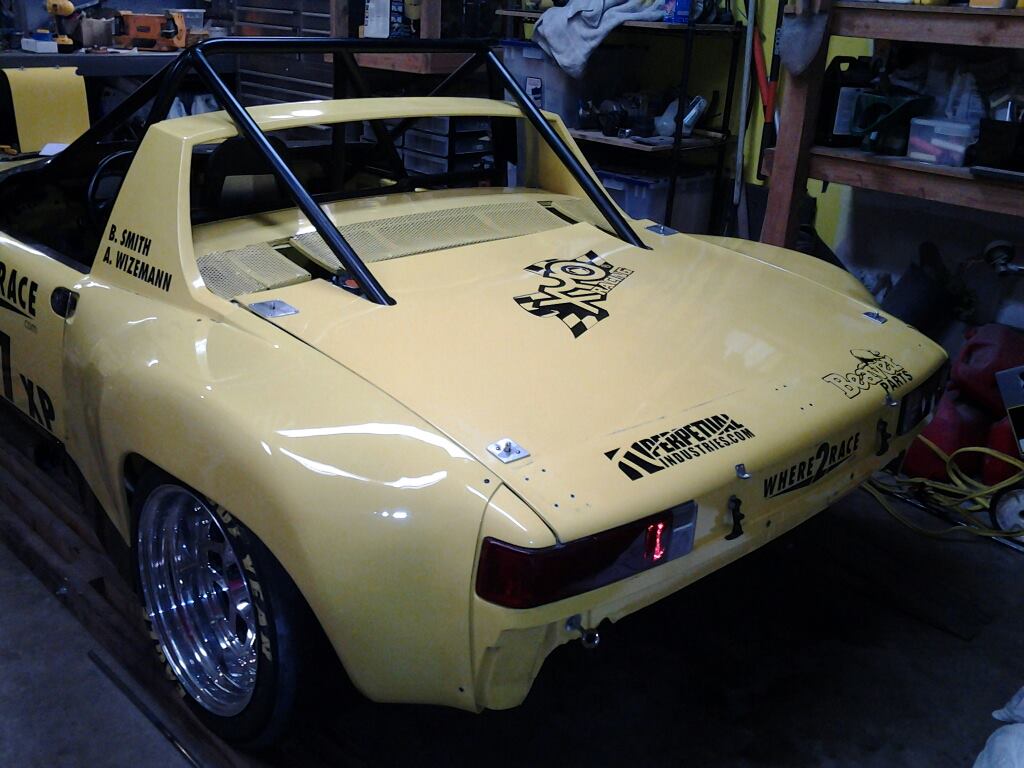
The replacement is a new dual element rear wing from Dauntless Racing. The height and location is dictated by the rules for an open cockpit car. Here is the wing with the custom uprights mocked up.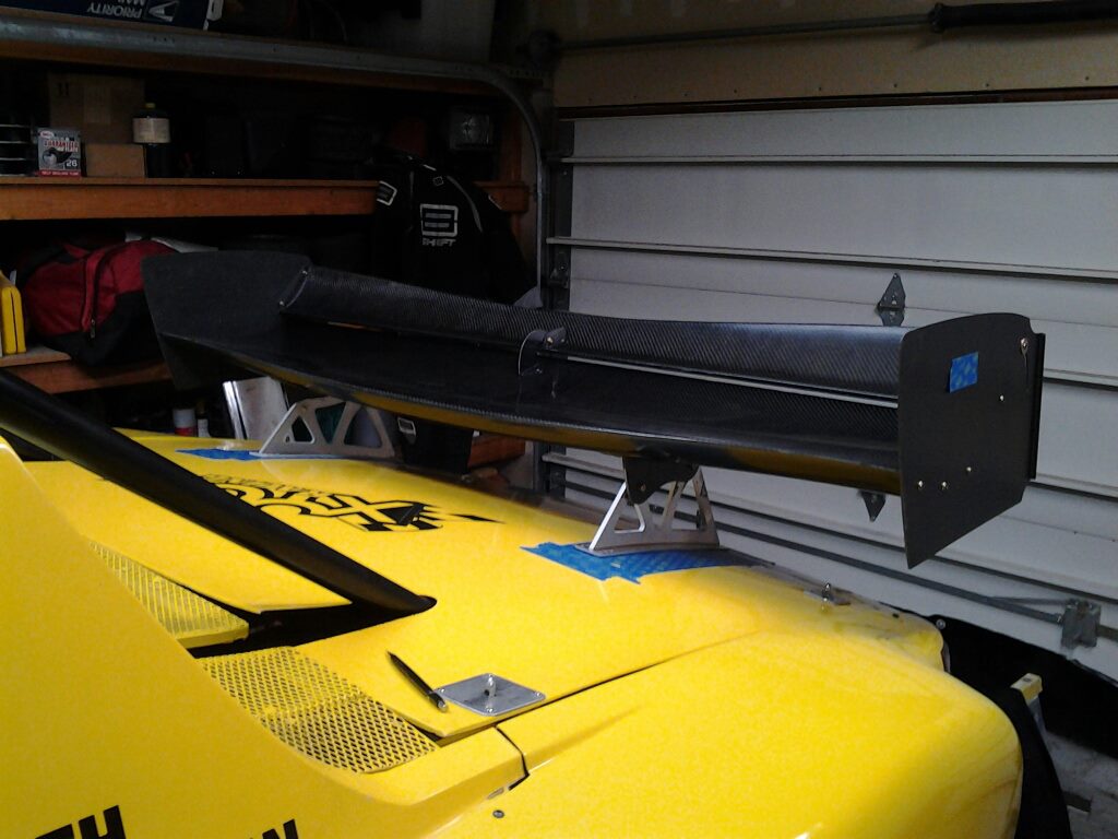
Here is the wing's final mounting location and a new rear bumper in place to complete the look. 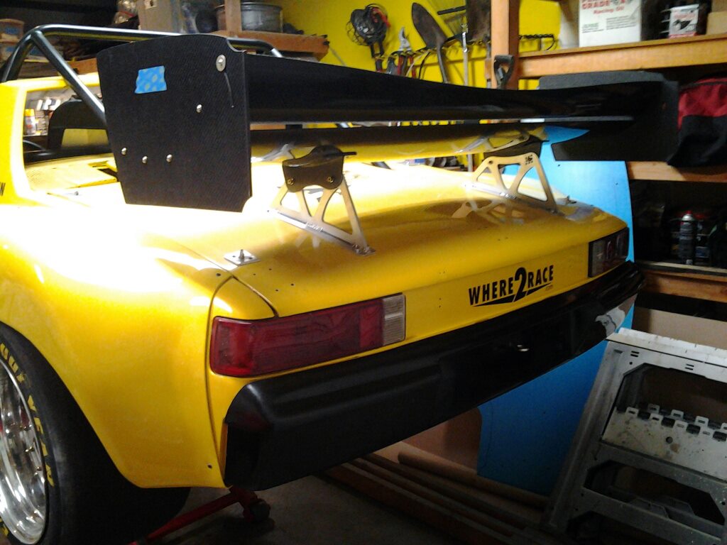
To support the decklid, I made uprights in the rear trunk to provide support under the wing.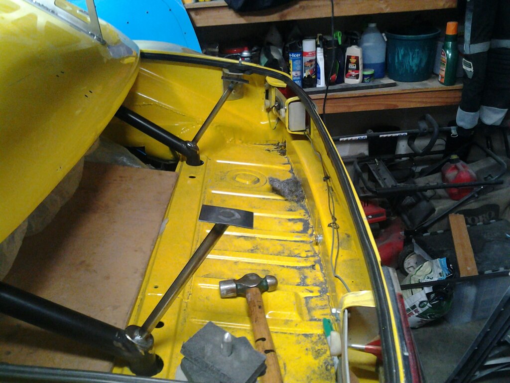
Aerocatches added to rear decklid for ease of use and adjustability. Makes removal so much easier.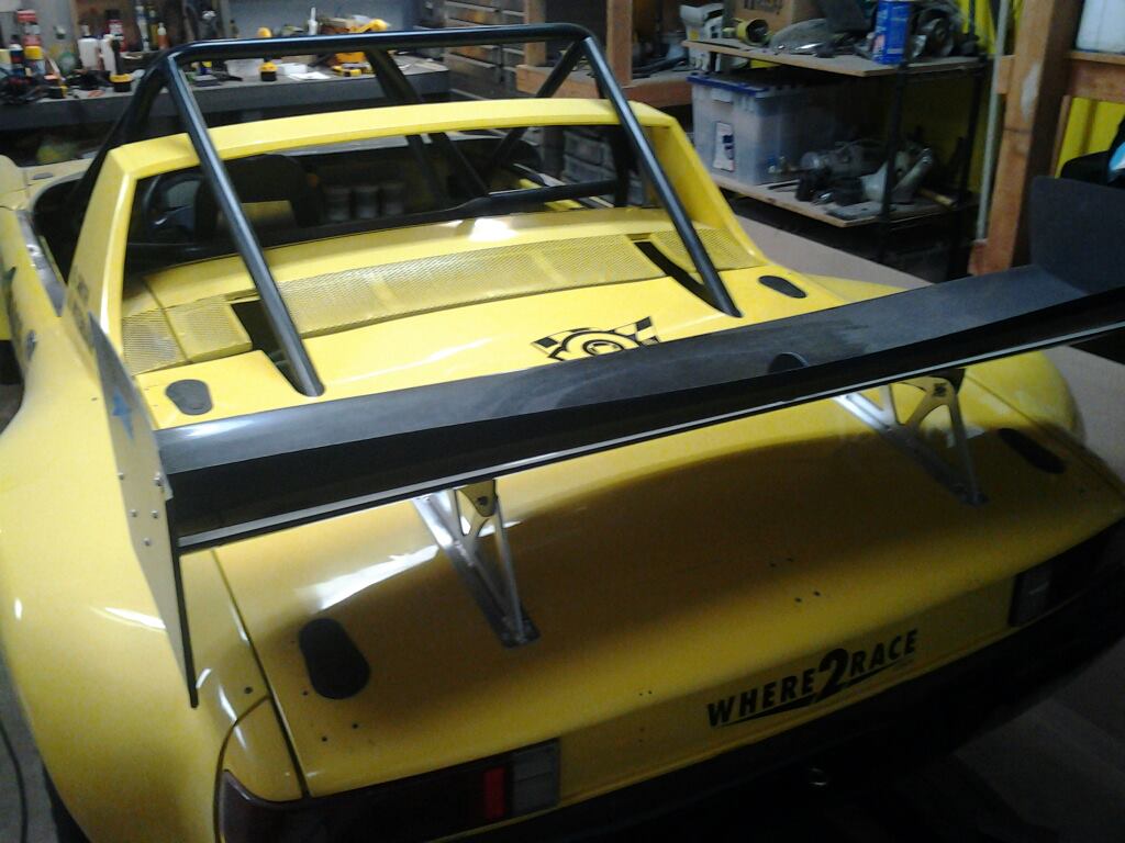
Loaded up and rear for battle. 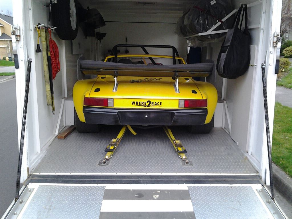
Posted by: Britain Smith Mar 20 2013, 12:47 PM
We took the car down to sunny California this past weekend and run with the Golden Gate Region PCA on Sat. to do some aero testing and set-up changes. Overall very happy with the new Dauntless as small adjustments in the wing flap yielded noticeable changes in grip.
Here is the car at the event.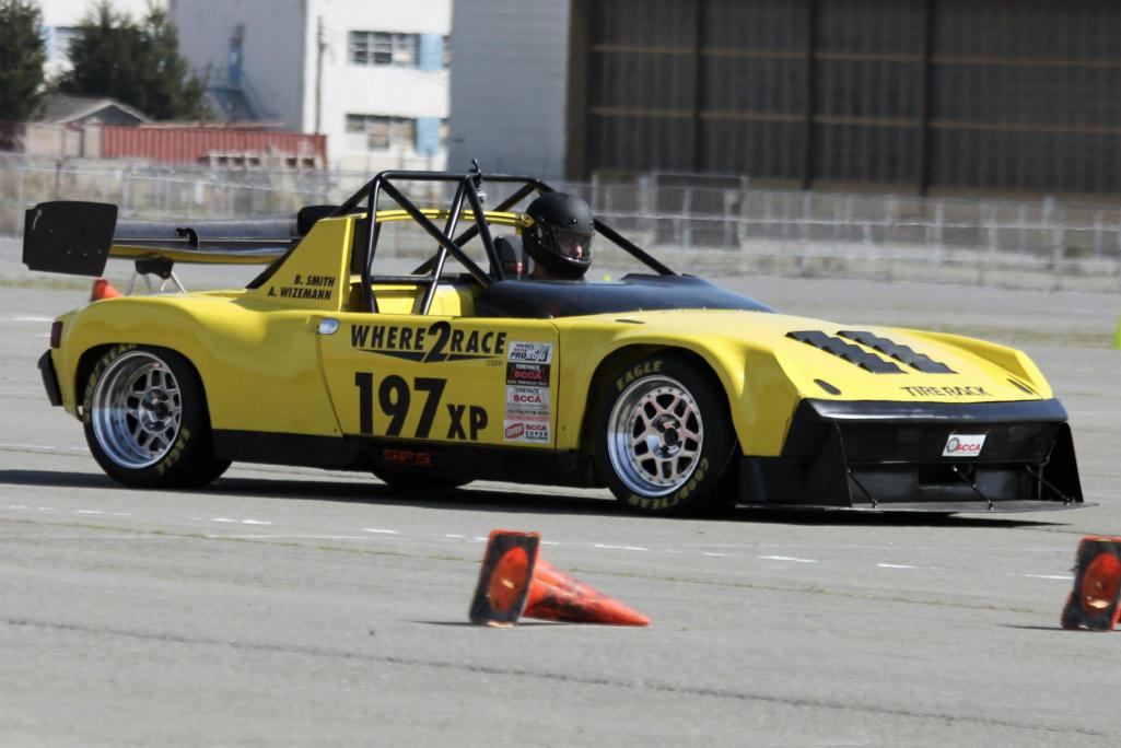
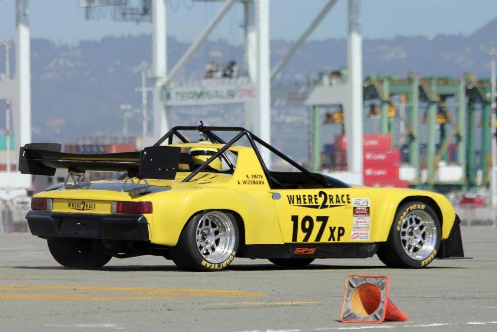
Here is a video of my fastest run.
http://www.youtube.com/watch?v=ScXdmeyrU_E
Posted by: Britain Smith Mar 20 2013, 12:59 PM
On Sunday we ran with the American Autocross Society down at Marina, CA. We were only able to get a couple of runs in before the transmission called it quits.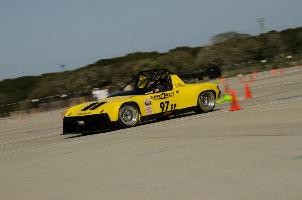
Here is a video of my first run which was still good enough for a top10 finish, but well off the pace of TTOD.
http://www.youtube.com/watch?v=SAKjxuRbeDg
At the end of my co-drivers second run, he appears to have downshifted abruptly without blip throttle to match the RPM's. You can hear on the video of my co-owner's run in which it occurs, the tire scratch a bit, and loud grumbling comes from the trans. We broke several teeth off the 2nd gear on the mainshaft. The car was shut down quickly so no other damage appears to have occurred. The parts could have had previous damage from launching, but in the end it doesn't matter who or how it broke...it will be fixed and we will move on.
Here is his video:
http://www.youtube.com/watch?v=OBSnQT3Kcw4
It will be easy to fix as parts are stock...but time to look for a stronger solution.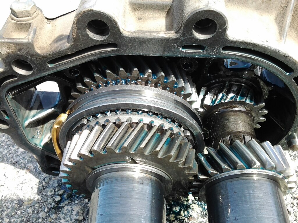
Posted by: BMiller Mar 20 2013, 09:23 PM
Those Cali run videos are awesome! Nice work!
Sorry to hear about the trans, but looking forward to more videos after the fix.
Posted by: Rod Apr 5 2013, 06:17 AM
Was having a look at a website that my friend has his BMW build on and what did I come across????
http://www.build-threads.com/build-threads/another-wrx-powered-porsche-914/#more-7050
Nice..
Posted by: Runman07 Jul 8 2013, 09:55 PM
Sweet build man! Spent the last few hours reading this. As a fan of the boxer motor (and subaru's in general (I own a WRX)) you are doing everything right! Light weight plus twin scroll ej207 power is definitely a recipie for disaster (in a good way).
to really do it right you should look into getting a Subaru transmission to mate up to that. And for that task I would suggest getting either a JDM Spec or a USDM Spec 6 speed. Why a 6 speed you might ask? Because the transmission is built better and the wrx 5 speeds are notorious to blow up. (Albeit its stronger than the 901). Just my .02.
Looking forward to seeing moar updates!!!
-Brant
Posted by: Britain Smith Jul 8 2013, 10:01 PM
Thanks Brant.
I actually have been working hard on something even better than the Subaru trans. Details will come soon.
-Britain
Posted by: Britain Smith Jul 11 2013, 09:51 AM
Little update on what I have been working on for the last 6weeks or so. After blowing up four 901 transmissions in two weeks, I decided to sell off the good parts and focus on fixing the problem instead. The solution to that problem is a 930 transmission and with everything I do, leaving it stock is not good enough.
Here is the 901 transmission in all it's glory. All pulled apart for the last time. I shed a quick tear...
BTW, final weight with fluid was 78lbs.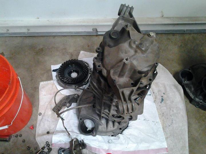
First fitting of the 930 box. Took a little bit of modifications to the top of the case and around one of the adapter bolts, bit is in place. Damn thing is big.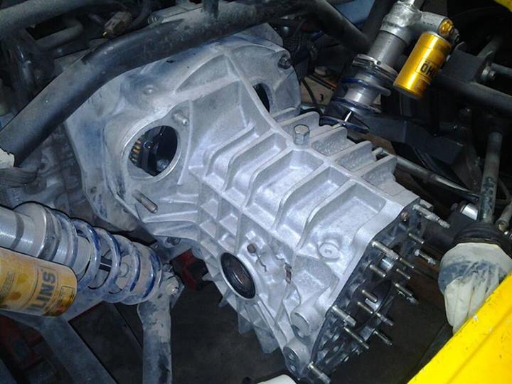
I had to cut off a bit of excess metal around the shock mounts to clear the side plate cover studs.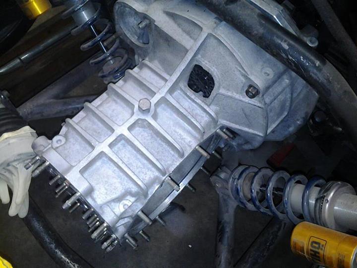
Going to need to cut the rear trunk out a bit to clear the intermediate housing. Thinking about a support bar between the cage mounts in the shape of the blue paper towels.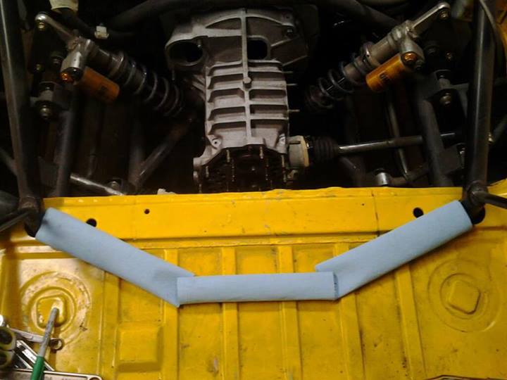
Rear trunk floor removed...makes working on the transmission easy.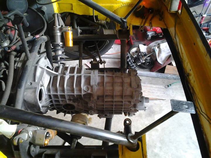
Posted by: Britain Smith Jul 11 2013, 09:55 AM
Now it is time to start working on the trans mount and adding a bar between the cage mounts.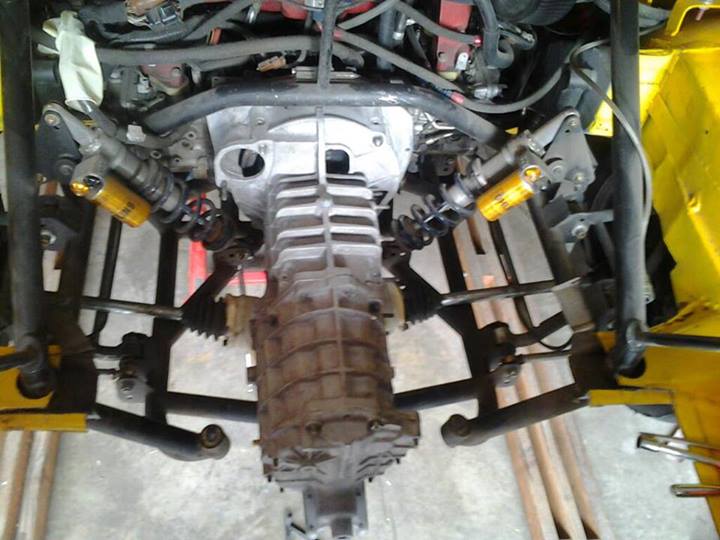
Adding strength back after removing the rear trunk. You will notice that I left the bottom part of the trunk floor in place to keep the sub-frame in position while adding additional supports.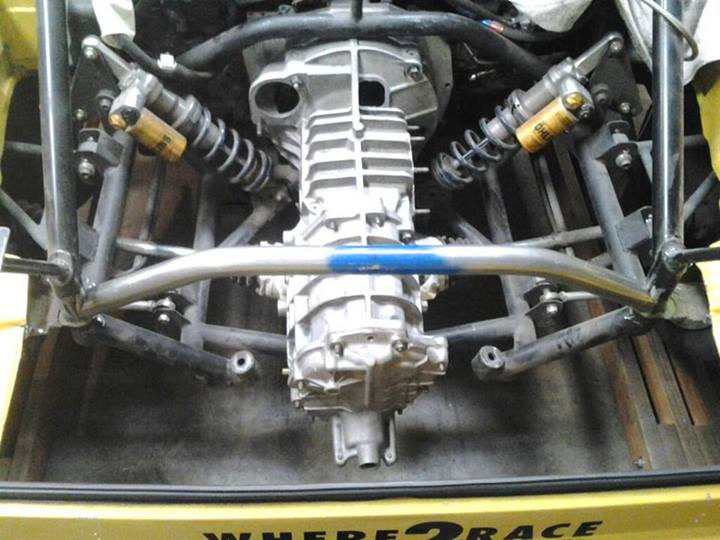
More of the trunk floor cut away. I am doing this in sections to keep the position of the subframe from shifting.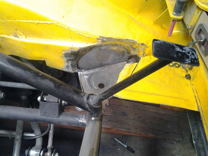
Scab plates in place to cover the hole in the chassis. Tubing added to tie the subframe connections in place.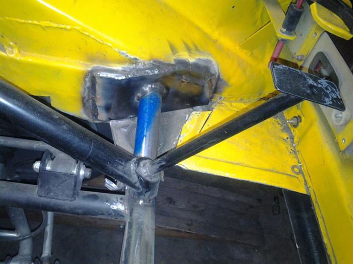
Trunk/Chassis modifications completed. Truck cut out and structural bars put in it's place.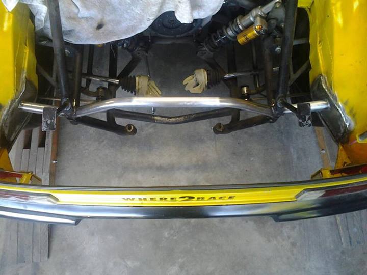
Back view of the rear structure. Lots of room back here to work on the trans from above.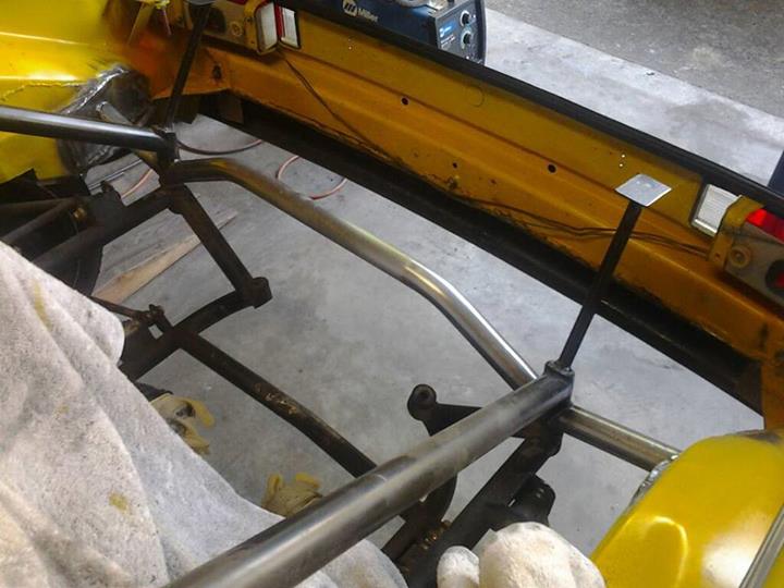
Transmission case back in place.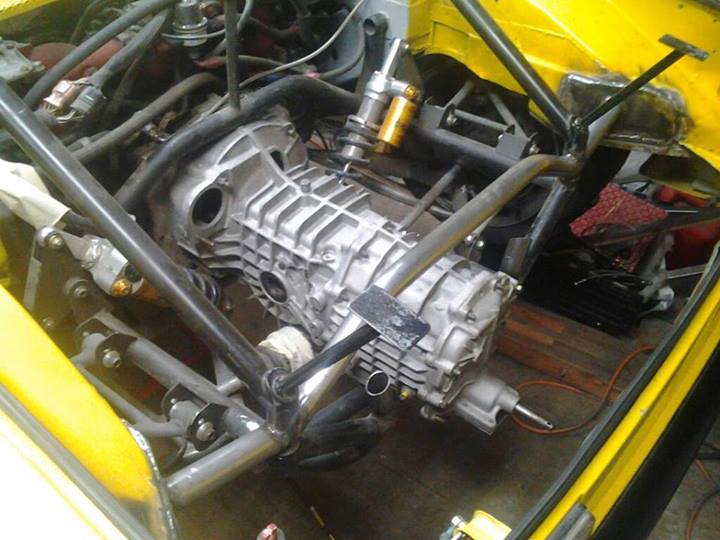
Posted by: Britain Smith Jul 11 2013, 09:57 AM
Ready to start bending tube for the transmission support.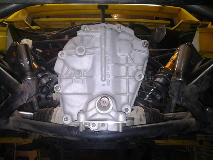
1" DOM tubing bent for the transmission mount. Need to finish up the sub-frame mounts next.
Side view of trans mount.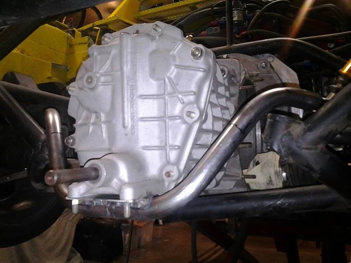
Trans mount done.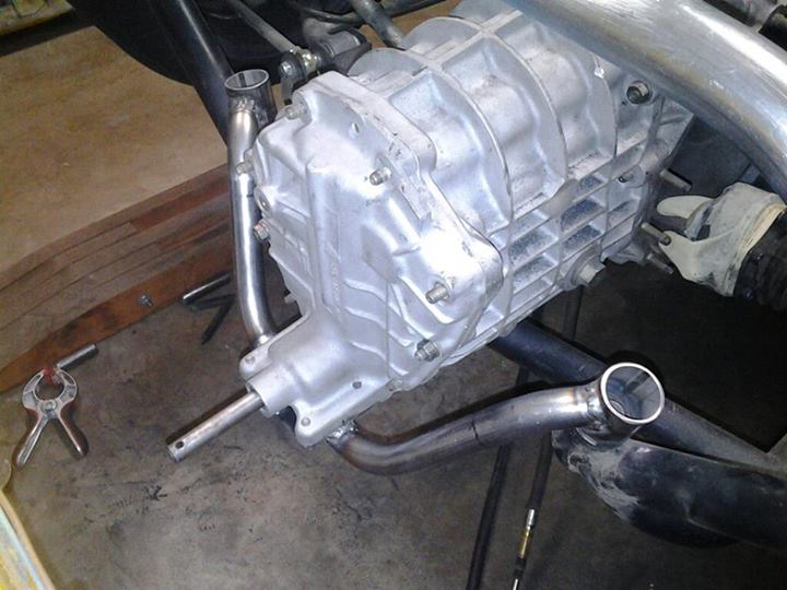
Posted by: Britain Smith Jul 11 2013, 09:59 AM
Another part of this adventure was dealing with the differences in bell housings depths between the 901 and the 930 transmission.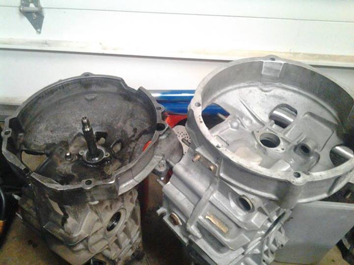
The deeper bell housing flange on the 930 trans puts the starter ring gear in a different location in relation to the flywheel. In addition, the 930 starter ring gear is 2mm larger diameter.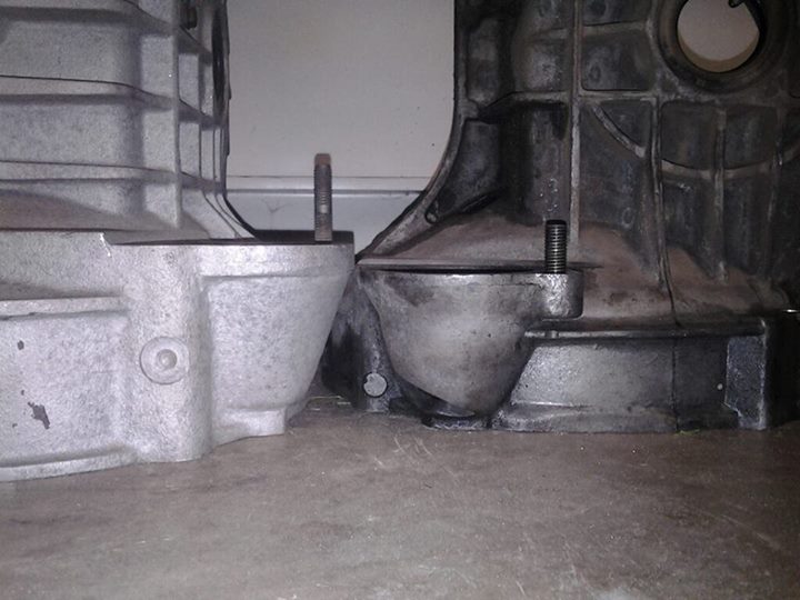
To adapt my 901/915 style flywheel to work in the 930, we had an adapter plate CNC machined. This will allow me to use my current flywheel/clutch set-up and a 930 starter ring gear.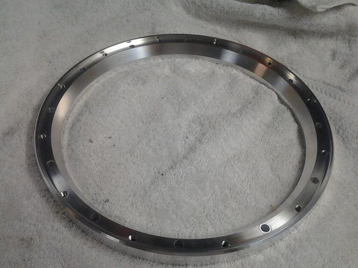
Front side view of the starter ring gear adapter.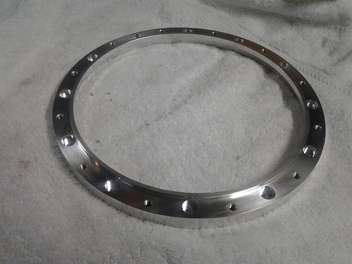
My current flywheel with 915 starter ring gear removed.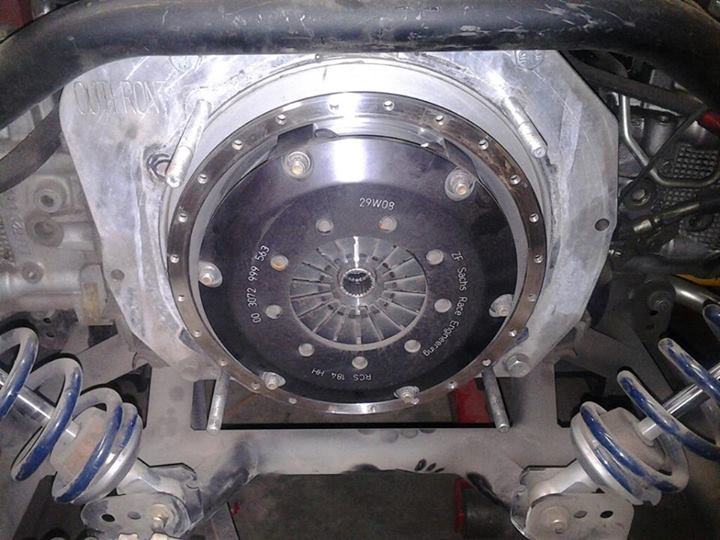
Adapter in place.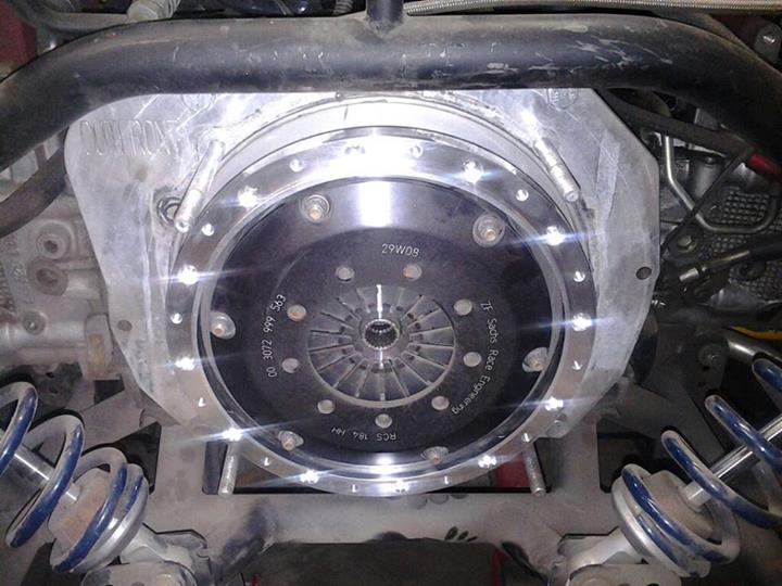
930 starter ring gear bolted on. This put the starter ring gear in the correct location in the bell housing.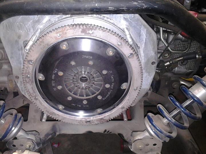
930 splined clutch plates to replace the 901 splined plates that I had.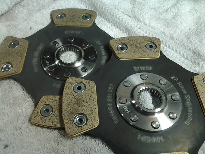
Posted by: Britain Smith Jul 11 2013, 10:00 AM
Christmas in July! 930 Limited Slip from Matt Monson at Guard Transmission.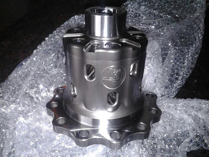
When you run a 911 gear box in a mid-engine configuration, you have the either run the box upside down or flip the ring gear to get it to spin the other direction. For a 930 transmission, this requires significant machining to both the ring gear and the case. This is the stock ring gear before machining.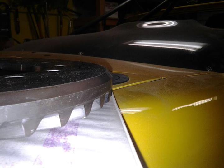
Here is a stock Diff sitting in the case. You can see part of the area that the case has been machined.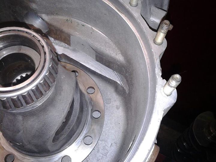
Ring gear chucked up on the lathe.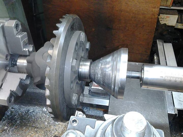
Cutting hardened steel...molten lava coming off.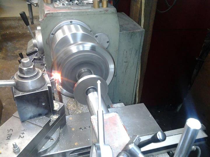
After about 45mins of cutting...back of the ring gear cut to fit the case. There was additional cutting required after this, but didn't get a picture of it.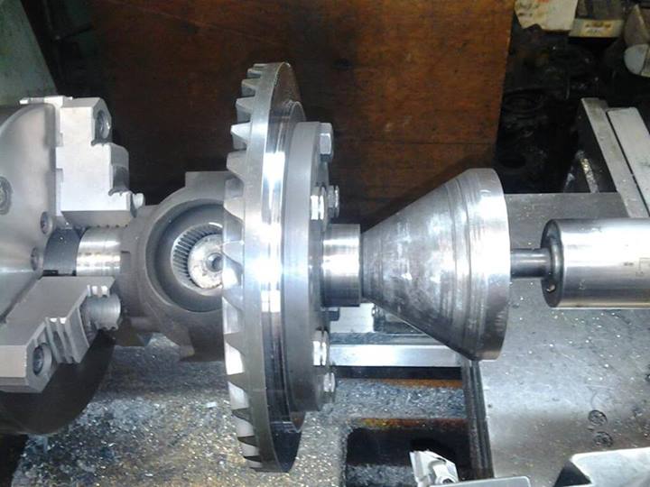
Posted by: Britain Smith Jul 11 2013, 10:02 AM
Another thing we wanted to do was use the same hydraulic throw-out bearing parts that were used on the previous transmission. To do this we had to machine about 8mm off the guide tube mounting location in the bell housing.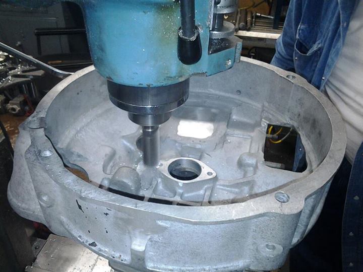
Cut thru the case in one part...nothing a bit of welding can't fix.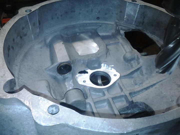
After a significant amount of welding and some more machining. The burn marks are from the epoxy melting.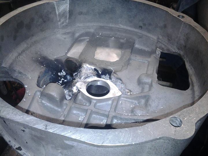
Additional material added to the inside for strength.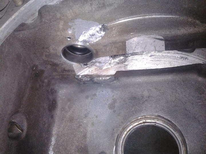
Throw-out bearing guide tube mounted in place after significant modification.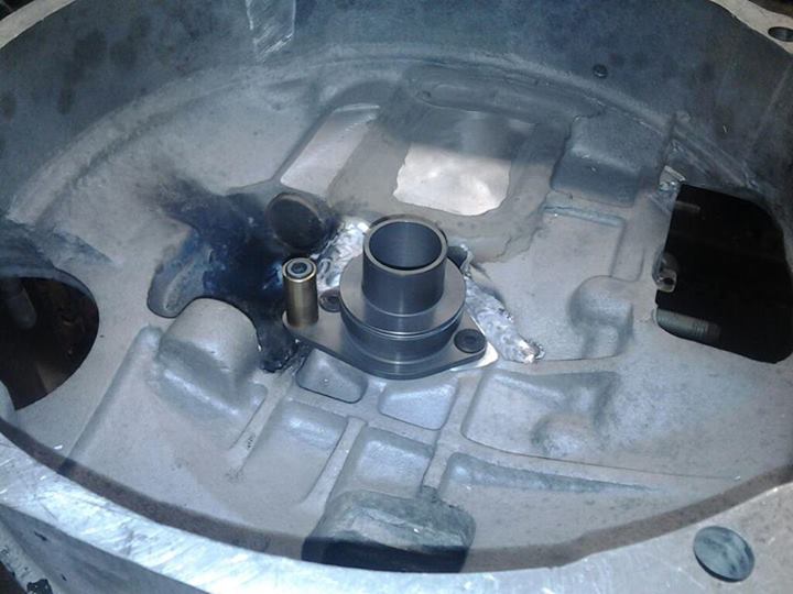
Hydraulic throw-out bearing mechanism in place.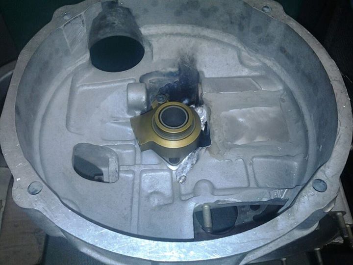
Because I am using the dual-plate clutch set-up, I had to source a early short bell housing mainshaft which has more spline engagement. Interestingly enough, this early mainshaft had a sealing surface machined in the bell housing area that allowed for the use of a 915 style input shaft seal and guide tube.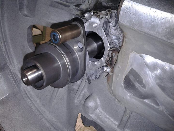
930 Shaft installed with the 915 release bearing carrier in place. Clearances are tight!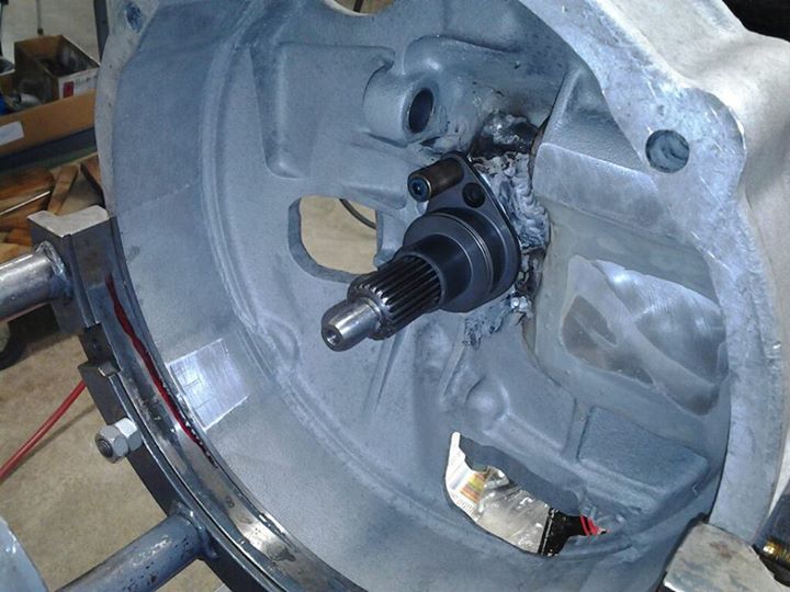
Hydraulic throw-out bearing in place for the last time. New fittings and lines with 45deg bends to run out the back of the bell housing.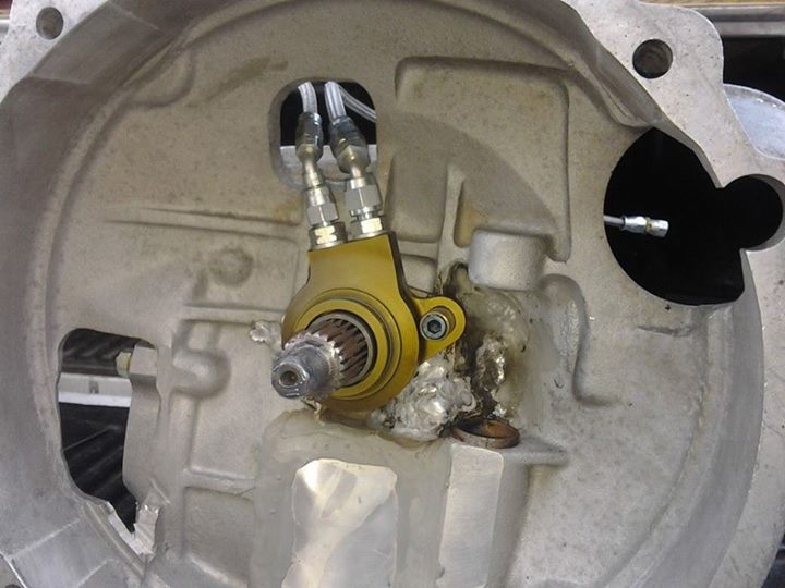
Posted by: Britain Smith Jul 11 2013, 10:05 AM
Another modification that we made was to make this box a 2-speed for Autocross applications. I did this on the 901 and it worked great. For this application, we ditched all the stock shift rails, yokes, etc. and just made a longer shift rod that came out the back of the transmission directly. This also reverse the shifter throw to make it match what I had on the 901.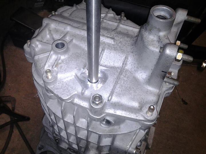
New shift rod location with a bung welded to the nose cone to hold the seal.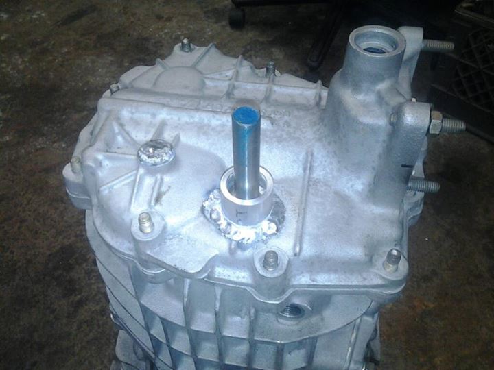
The longer shaft is the new one machined to match the stock rod.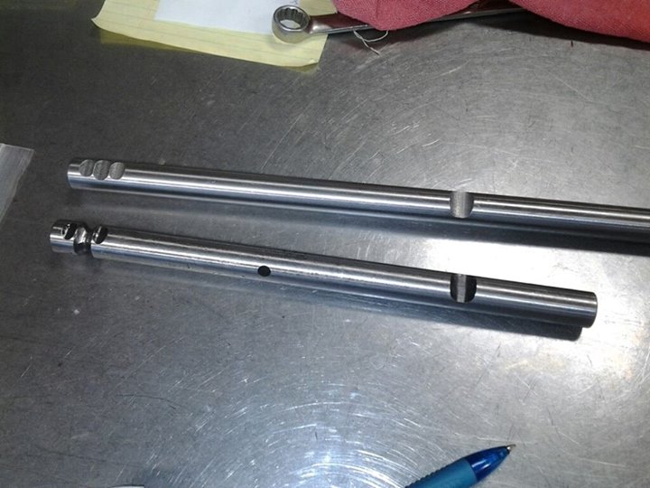
Now that we have all the parts in place, it was time for assembly. I left out the majority of the parts associated with 3/4 gear. I also cut out the center splined area for the reverse gear to further cut weight.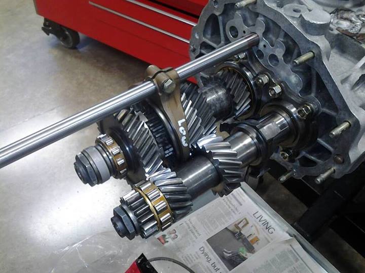
Dog gear parts. This transmission has no syncro's which will improve the shifting speed significantly over stock.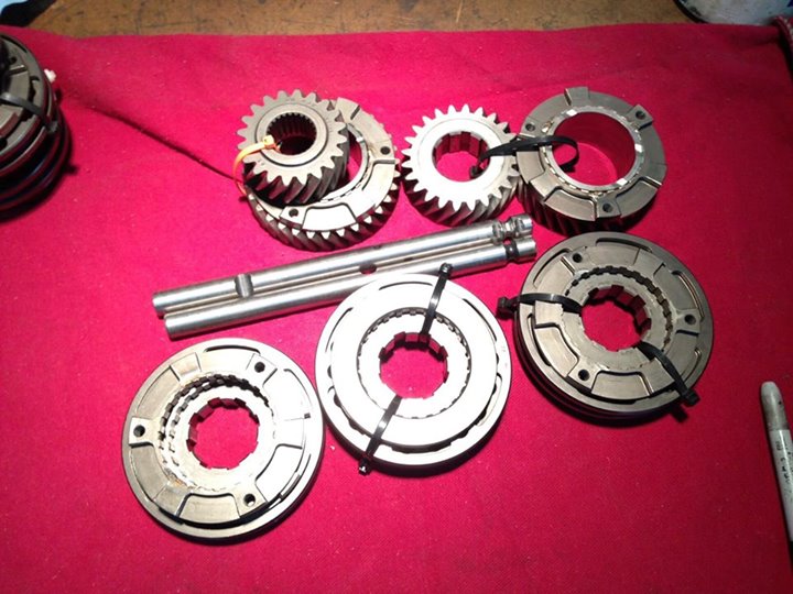
Transmission almost together and sealed up. Total weight with fluid was 116lbs...so I only gained 38lbs over the 901 set-up.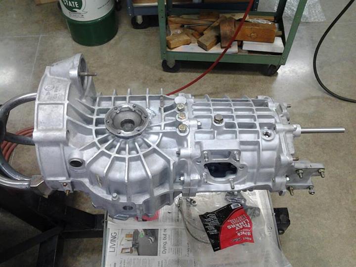
Posted by: Britain Smith Jul 11 2013, 10:06 AM
Here is a plate we fabb'ed up to hold the vehicle speed sensor and the clutch lines. 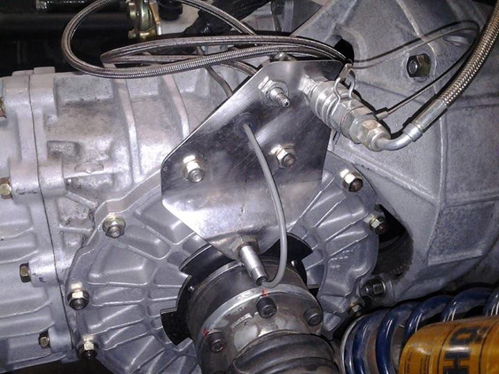
Transmission in place, everything hooked up, ready to fire!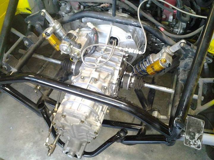
Success! After a couple of passes down my street I gave it a nice sponge bath.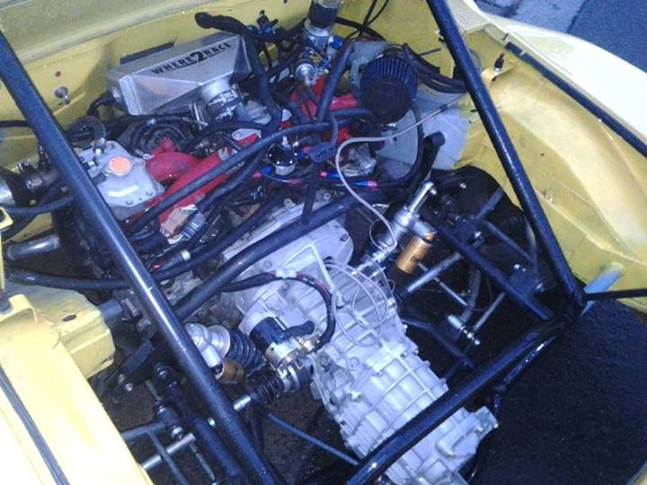
Posted by: J P Stein Jul 11 2013, 10:22 AM
Looks damn good.
As a first time out after such an amount of work, a National Tour event is not the ideal place......but there it is. Hope you find a co-driver & get some time on it on Friday, hopefully the bugs are few.......then the best of luck to ya.
Posted by: Drums66 Jul 11 2013, 10:53 AM
.....Yes it does!!....some fine work 

Posted by: FourBlades Jul 11 2013, 08:58 PM
Good luck man!
Show the world what a nearly stock 914 can do!
John
Posted by: Runman07 Jul 11 2013, 09:56 PM
hah! thats definitely better than what i had in mind! looks beefy and it should hold up for the life of the car and afterwords. good luck with that beast, looks like it should be a helluva lot of fun to drive!
-Brant
Posted by: Britain Smith Jul 28 2013, 01:15 AM
Here is a video from this weekend Autocross with the PacNW Region PCA in Packwood, WA. Took TTOD with this run and had an even faster run in the "fun" runs later in the afternoon.
http://youtu.be/UNr9tqK0LrI
Posted by: cary Jul 28 2013, 09:29 AM
I think if you push the right pedal harder it will go faster. LOL.
Video doesn't do justice to how fast its really going.
Posted by: Randal Jul 28 2013, 10:38 AM
Here is a video from this weekend Autocross with the PacNW Region PCA in Packwood, WA. Took TTOD with this run and had an even faster run in the "fun" runs later in the afternoon.
http://youtu.be/UNr9tqK0LrI
Congrats on getting the new transmission fitted and operational. Car goes like a rocket.
How did your co-driver do with the new setup?
Posted by: sean_v8_914 Jul 28 2013, 10:38 AM
truly epic modified mayhem! i love this monster
Posted by: Britain Smith Jul 28 2013, 01:13 PM
Here is the "fun" run video where I pushed the car another 0.5secs faster. You can see in a couple of spots where I run out of first gear and I am riding the rev limiter. You can also see towards the end where I am running out of front end grip due to aero load from the rear wing. Time for some front end aero improvements.
https://www.youtube.com/watch?v=gtSSZLxkqtI
Posted by: J P Stein Jul 29 2013, 07:43 AM
A bit of additional info:
Brit's rev lmiter is set at 8400 rpms......that is right around 60 mph in first & 90odd mph in second. At this point, this car is not good enough to trophy at the SCAA Nats in XP. He still needs to pick up around 1.5sec per run to run at the pointy end of the field.
Apparently, this is meaningless drivel to causal AXers.
Posted by: URY914 Jul 29 2013, 07:54 AM
Where are you going to find 1.5 seconds?
Posted by: DBCooper Jul 29 2013, 08:20 AM
Wow, reminds me of the F1 ride-along videos, not the same world I live in. That's the real rare-air end of things so I don't have any experience, but I'm having a hard time imagining a whole 1.5 seconds. Maybe because I can't stop thinking about how happy I'd be to go "just" that fast?
Are you sure, JP? Do you have other car's times on the same course, or some other way to compare? Seems several orders of magnitude faster than the same car with the Porsche suspension and the six.
Posted by: Randal Jul 29 2013, 08:55 AM
Where are you going to find 1.5 seconds?
Drive it harder, tighter and smoother through the corners. Don't rely on the point and shoot approach.
The time is there, just have to become one with the car, which will not be easy as the speed transition is somewhat brutal.
Posted by: J P Stein Jul 29 2013, 09:47 AM
A couple of the DP guys Brit runs against locally are "at the pointy end" of their class at the Nats.......2 sec slower than the XP winner (a nice round number). I'll admit that this is not a scientific measurement but PFCE. (Pretty ******* Close Enuff)
Right now I think ithe 1.5 sec is the aero and the nut behind the wheel.
Brit's had very little practice with the current set-up....tain't like riding a bicycle, eh?
He now has to school hisself about the building/tuning the car & not just driving. He's making up ground on them DP guys..... Last year he was behind them....not now.....progress is gud. Right now he finds himself into a high speed aero understeer....new ground to plow.
That said, one can understand that the XP winner is not sitting on his hands either.
Posted by: Cap'n Krusty Jul 29 2013, 09:54 AM
Whatever. I, for one, am impressed. I saw the car while under construction last year. The knowledge, the willingness to try things, the attention to detail as things came up and were changed on the fly, everything just oozes focus and dedication, combined with forward out-of-the-box thinking. If that second and a half needs to be found, I'm sure it will be! Soon.
The Cap'n
Posted by: Britain Smith Jul 29 2013, 10:11 AM
The most recent changes have really improved the cars performance. I now have a transmission that can take the power...which means I can turn the power up to where the turbo is the most efficient. The motor is now much more responsive and pulls hard. My issue here is gearing choices which is easy to fix...just need to find the gear I want to go with.
The last couple of events I have started pulling away from the fastest competition here in the PacNW. At the National Tour I raw timed the 780whp Nissan GTR by a healthy margin, at the ProSolo I raw timed the fastest DP cars in the country by over a second, and this past weekend I raw times another very quick DP by at least 2secs. With more time behind the wheel and not under the car I am getting faster.
I would say that the additional time needed to catch the fastest XP cars is half car setup and half driving. High speed understeer seems to be the biggest limiter at the moment. I am also about 40lbs overweight and I have plans for that.
-Britain
Posted by: Britain Smith Jul 29 2013, 10:12 AM
Where are you going to find 1.5 seconds?
Drive it harder, tighter and smoother through the corners. Don't rely on the point and shoot approach.
The time is there, just have to become one with the car, which will not be easy as the speed transition is somewhat brutal.
Hey Randal...you going to make the Medford Enduro event this year?
-Britain
Posted by: Dave_Darling Jul 29 2013, 10:31 AM
I've met you--you don't have the weight to lose! Maybe the car does, but...
I have no idea if lower-speed experience means anything to where you are right now, but you still seemed to be a little behind the car in a number of spots, like in the slaloms. The "fun run" was better in that regard, but I could see the push in the sweepers.
In my car, I'd just try to drive around the push (drive deeper into the corners, etc.) but you have a lot more options open to you.
I think you've got another half-second on that particular course that I can see, but it's all in little dribs and drabs. More that that will have to come from improving the car some more (the high-speed push you mention) and from driving stuff that I'm not good enough to see.
--DD
Posted by: Britain Smith Jul 29 2013, 10:39 AM
I thought the same thing about the slalom when I watched the video. However, if you listen to the motor you can hear that I am accelerating thru the slalom which puts me right where I want to be on the exit. You no longer need to lift rotate like you have to do on stock 914 suspension. That is a 26pace slalom and I am on the rev limiter which is about 62mph.
-Britain
Posted by: Randal Jul 29 2013, 01:19 PM
Where are you going to find 1.5 seconds?
Drive it harder, tighter and smoother through the corners. Don't rely on the point and shoot approach.
The time is there, just have to become one with the car, which will not be easy as the speed transition is somewhat brutal.
Hey Randal...you going to make the Medford Enduro event this year?
-Britain
I'm planning on going Britain. Hope you'll be coming as well to uphold or improve upon your great time last year.
I'm doing pushups every day now, so no limp arms at the Fall event!
Posted by: Randal Jul 29 2013, 01:23 PM
I've met you--you don't have the weight to lose! Maybe the car does, but...
I have no idea if lower-speed experience means anything to where you are right now, but you still seemed to be a little behind the car in a number of spots, like in the slaloms. The "fun run" was better in that regard, but I could see the push in the sweepers.
In my car, I'd just try to drive around the push (drive deeper into the corners, etc.) but you have a lot more options open to you.
I think you've got another half-second on that particular course that I can see, but it's all in little dribs and drabs. More that that will have to come from improving the car some more (the high-speed push you mention) and from driving stuff that I'm not good enough to see.
--DD
Reminds me of a question I had. Are you really installing a Guard limit slip as opposed to a torque bias differential? I got rid of all the understeer I had with the Guard LS when I installed the Guard TB. For Autox Guard's TB's really work; I mean I haven't had any under steer since I went with the TB and Avons. In fact I haven't even figured out the limits yet.
Posted by: J P Stein Jul 29 2013, 02:19 PM
Post #502 pic shows a TB diff.
Note the helical cut gears visible through the slots in the housing.
Posted by: Britain Smith Jul 29 2013, 02:28 PM
Yep...Guard TBD! Best option for AX.
Posted by: Randal Jul 29 2013, 08:18 PM
Yep...Guard TBD! Best option for AX.
Magic really.
Posted by: BKLA Jul 29 2013, 09:42 PM
Check out britain's YouTube page. He has some new uploads of recent runs with the new gearbox.
Posted by: Britain Smith Aug 19 2013, 05:31 PM
The Where2Race Porsche 914 had a great outing this past weekend at the NWR SCCA Solo Autocross #7 in Packwood, WA. Took overall top time both days and grabbed 2nd in PAX on Sunday. The course was fast and challenging, with several opportunities to make mistakes. The car ran great, new gearing was much better. Here is a video of my fastest run...enjoy.
http://youtu.be/oFl0zJtdnQM
Posted by: DBCooper Aug 19 2013, 07:58 PM
Wow. Britain, I'm proud that I post on the same board that you do.
Posted by: J P Stein Aug 20 2013, 08:41 AM
Wow. Britain, I'm proud that I post on the same board that you do.
Yeah, me too.
Folks might like to know your speed in gears.....the limiter was talkin' at ya in first.
Didn't hear in it second. Looked pretty damn fast to me tho.
Posted by: Britain Smith Aug 20 2013, 10:00 AM
Wow. Britain, I'm proud that I post on the same board that you do.
Yeah, me too.
Folks might like to know your speed in gears.....the limiter was talkin' at ya in first.
Didn't hear in it second. Looked pretty damn fast to me tho.
According to my calculations, should be 62mph in first and 80mph in 2nd. I just got a new data logging set-up with GPS to get accurate speed info.
-Britain
Posted by: Britain Smith Oct 11 2013, 09:17 AM
Here is my video from the Siskiyou Sports Car Club Fall Enduro 2013. It is 5laps around a large kart track in which you hit speeds a touch over 90mph down the straightaway. I have been working to make my car faster every year and this year I finally broke the 21year overall track record set in '92 with a time of 3:38.115secs.
Here is a breakdown of my runs over the years:
2010: Porsche 2.7L Engine/Porsche Suspension: 3:52
2011: Subaru 2.0L Engine/Porsche Suspension: 3:49
2012: Subaru 2.0L Engine/Lotus Suspension: 3:42
2013: Subaru 2.0L Engine/Lotus Suspension/930 Trans/Aero: 3:38
http://www.youtube.com/watch?v=Jg7KmOfUolk&feature=youtu.be
Here is another video showing side by side lap comparison between my co-driver Alan Wizemann and myself. He did a great job and this video should really help him improve his time next year.
http://www.youtube.com/watch?v=lmECCM5ppqo&feature=youtu.be
Posted by: Dave_Darling Oct 11 2013, 10:48 AM
Good lord! It looks like it's quite hard to effectively use all of the power that thing has.
And you didn't exactly leave a lot of time out on the track, did you?
I still remember instructing you in your very first autoX ever--wasn't it at a WCR? The 1.7 with the "OH PLEASE SOMEONE GET ME A SWAY BAR" suspension. (And I think you even beat my time in my 2.0!!)
--DD
Posted by: DBCooper Oct 11 2013, 10:54 AM
Wow, what a ride. But both you guys need to work on conditioning. See the way your heads snap back whenever you accelerate? That car's stronger than you are! To the gym!!
Posted by: FourBlades Oct 11 2013, 10:55 AM
We are definitely not worthy!
John
Powered by Invision Power Board (http://www.invisionboard.com)
© Invision Power Services (http://www.invisionpower.com)