Printable Version of Topic
Click here to view this topic in its original format
914World.com _ 914World Garage _ Wiring up a 3.2l Motronic FI engine
Posted by: jim912928 Mar 11 2011, 05:46 PM
First, there are too many people to thank in here for all of the knowledge and advice on what they have done hooking up their 3.2l conversions...thanks all!
Let’s start with identifying all of the wires on the Harness:
#1 Black wire (thick): battery + (on the 911 was connected directly to the + battery post)
#2 Black wire: ignition coil (must tap into power for start and run)
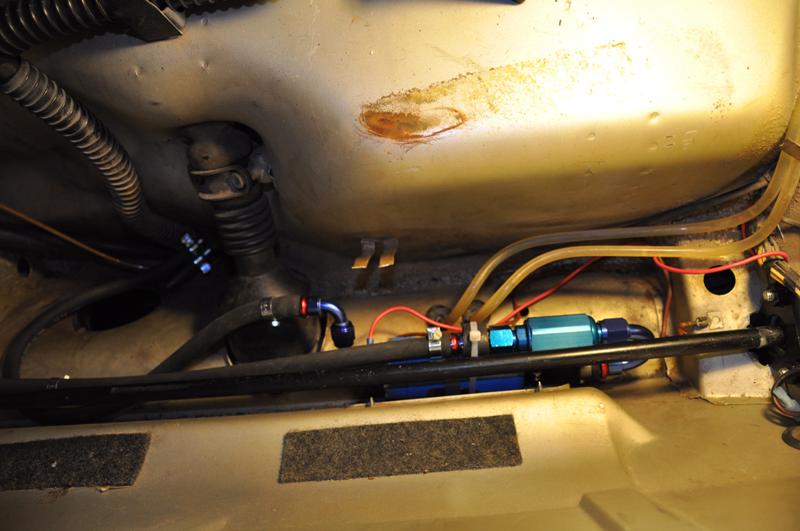
#3 Red wire: power feed to fuel pump (put an inline 25 amp fuse)
#4 Black wire: DME relay (must tap into power for start and run)
#5 Green wires: do not use, these branch over to the air conditioning components in the 911 front trunk
#6 This connector has three wires in it:
........Yellow wire: tap into 914 start only from ignition switch
....... Black/Violet wire: to tach (attach to terminal #2 on 911 tach)
....... Black wire: to tach (attach to terminal #1 on 911 tach)
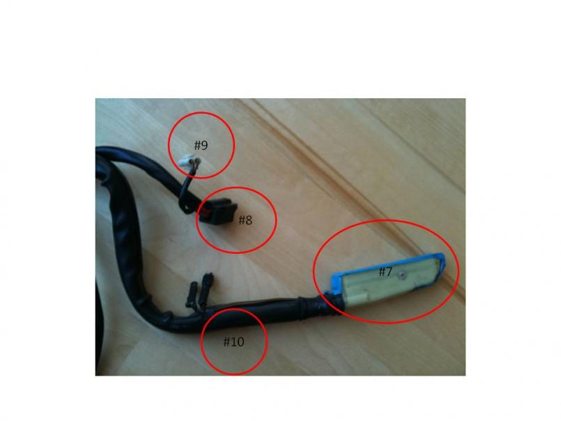
#7 Connects to Motronic Control Unit
#8 Connects to DME relay
#9 Connects to Altitude Sensor
#10 Leave alone unless this is an original California Car. If California…connect together (this is per the current flow diagram)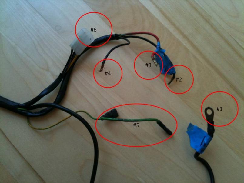
Posted by: jim912928 Mar 11 2011, 05:49 PM
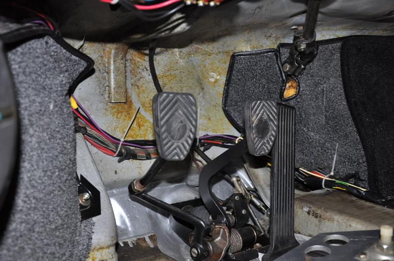
Now, I placed the Motronic Unit on the passenger side floor under the seat (I needed to raise the seat for it to clear). The hole I made to extend into the engine compartment I drilled out the indent near the floor. This brings it through kind of like the main harness. 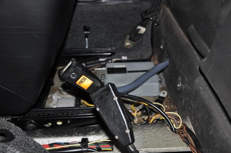
Once in the engine compartment I drilled another hole near the hell hole area and thread it through there. I used the original 911 grommet when going through the firewall and got another grommet from Ace Hardware for passage through the engine shelf. 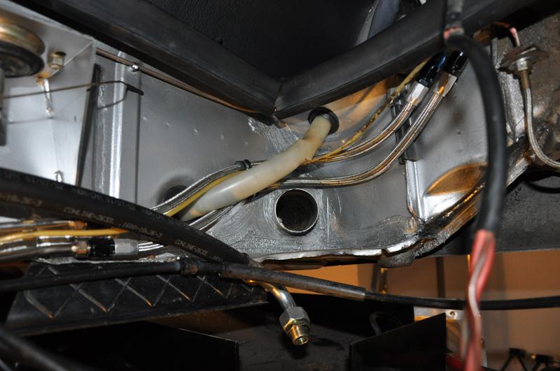
Once in the engine bay…I routed it so I’d branch to the engine from behind and secured with rubber lined clamps.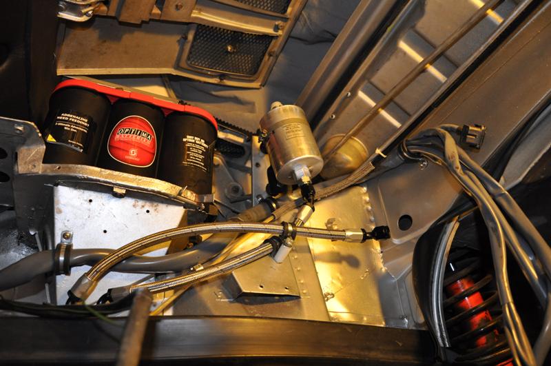
Posted by: SirAndy Mar 11 2011, 05:57 PM

Posted by: jim912928 Mar 11 2011, 05:58 PM
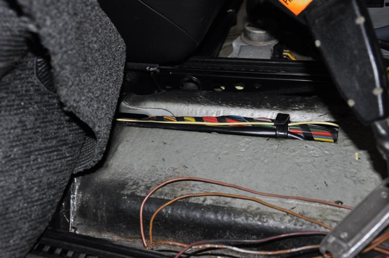
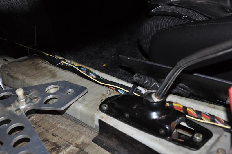
Now, in the passenger compartment, I routed all of the wires (1 through 6 noted above) through the tunnel alongside the original harness. I used color coded wire to extend to their final destinations. 
Posted by: jim912928 Mar 11 2011, 05:59 PM
For the #1 wire (B+) I connected directly to an open male connector on my fuse box (terminal 12) where all the big red B+ wires come in. This is “always on power”. I had to extend this wire and used matching gauge black wire (10 gauge).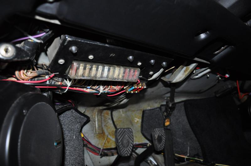
Posted by: jim912928 Mar 11 2011, 06:02 PM
For #2, #3 and #4 above I used a 3 pole fuse box from my 911 donor. The feed banks are all connected (all powered by 1 feed) and this wouldn’t work for the wires noted because the fuel pump is not getting power from the fuse panel. So I modified the fuse panel from behind to have only 2 banks interconnected. I mounted this fuse panel right next to the 914 one. Routed the Red fuel pump wire through it with a 25A fuse and continued the new wire up through the front wall and down to the fuel pump. The two black wires (ignition coil and DME) I connected to one side of the fuse block and connected 1 new wire from the feed side to an open “power on” spade on my fuse box (terminal 9). I used 14 gauge red and black wire in these applications.
Posted by: jim912928 Mar 11 2011, 06:02 PM
The # 5 wires are for the air conditioning…so I just taped those off
Posted by: jim912928 Mar 11 2011, 06:04 PM
The #6 yellow wire needs to be wired to ignition start only. Rather than pulling the wiring harness apart and tapping into the yellow wire from the ignition switch…I just ran a long yellow lead wire back to the passenger seat where I still have the seat belt warning stuff. I had bypassed this by connecting the two big yellow wires together…so I joined my new lead wire at this point. For this I used yellow 16 gauge wire to match what was coming from the DME harness. The black/violet wire I extended with 16 gauge violet wire and connected it directly to terminal 2 on the 911 Tach. The black wire I extended with a 16 gauge black wire and connected it to terminal 1 on the 911 Tach. Don’t forget to reconnect the 914 Red wires to terminal 5 on the 911 tach and the brown (ground) wires to terminal 6.
Here is a lame picture of the wrong side of the tach to be looking at...but I'm not going to pull the tach back out for a pic!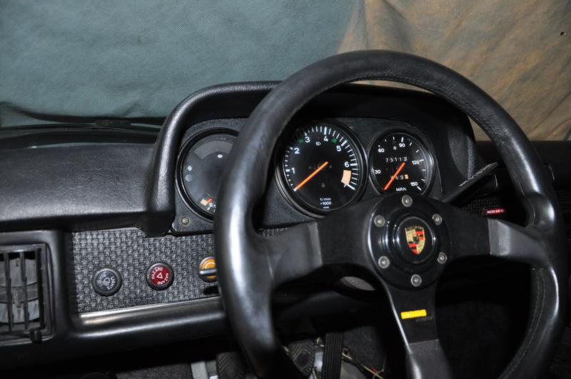
Posted by: jim912928 Mar 11 2011, 06:04 PM
#7 is simple..connect to motronic unit, #8 plug in DME relay, #9 plug in altitude sensor and #10 tape off or connect if you have a california engine/dme combo.
Posted by: jim912928 Mar 11 2011, 06:06 PM
Now for the engine bay, I eliminated the relay board and bought a conversion harness from Patrick Motor Sports. Here is how it is pinned out: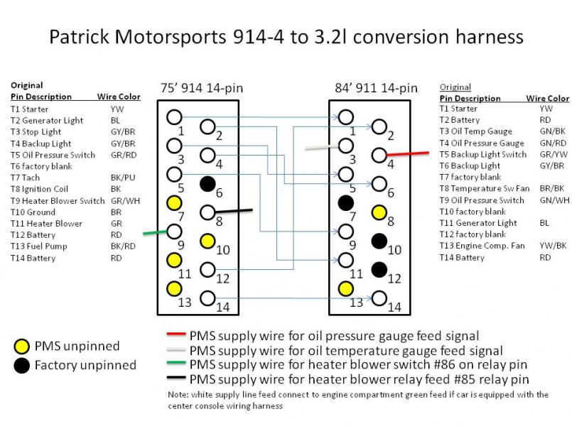
I haven’t yet connected up the temp/pressure gauges but those are just running leads back into my center console where I put in new VDO gauges that correspond to the 911 sensors. For the heater blower, I purchased a 914 relay socket and I’m going to wire it up exactly as it was wired on the relay board.
Posted by: jim912928 Mar 11 2011, 06:07 PM
So, that is it, after all of those connections everything worked as it did in the 911!
Posted by: echocanyons Mar 11 2011, 09:00 PM
Excellent and concise write up!
This is sure to save many folks a lot of time and headache (including myself)
Posted by: CaltranCraig Mar 21 2012, 12:35 PM
I know this is an old post, but it's a good one. How did you raise the passenger seat to fit the motronic unit?
Posted by: jim912928 Mar 21 2012, 01:21 PM
I'm not sure of the size...but I think they were 1/2" steel spacers...inside diameter the same is the bolts that bolt the seat rails to the floor brackets. Then I got the corresponding metric bolt 1/2" longer then the originals with a smooth shank that matched the length of the spacer. Took off the rails and bolted them back on with the longer bolts and spacers. At that height adjustment my seats (Konig's) still fit into the contour of the back pad.
Posted by: mepstein Dec 29 2014, 07:59 PM
This is an awesome post. Will save so much time in the future (for scatty  )
)
I know it's been a while but if you have any more tips you want to share, please do. Thanks!
Posted by: Cairo94507 Dec 30 2014, 07:52 AM
Yes, I had not seen this before and it is a concise how-to and will undoubtedly come in handy when my 3.2 gets installed in my car - hopefully around June 
Posted by: rhodyguy Dec 30 2014, 09:58 AM
A 'classic' thread for sure.
Posted by: fitchesbass Apr 24 2023, 10:02 PM
Apologize for bumping this thread from several years back. Informative thread thanks!
I am working through this wiring right now.
The project I inherited has motronic in the trunk. I may move it to the passenger seat location. The setup is using the Patrick motorsport 14 pin connector.
For item #6 — my comparable plug set has four wires — not three. See attached image. Any insights on the difference here as compared to the three wire referenced in this thread?
Thank you!
Attached thumbnail(s)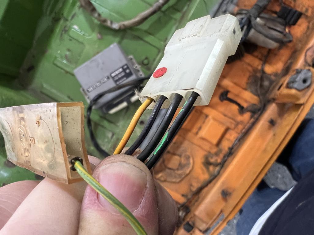
Powered by Invision Power Board (http://www.invisionboard.com)
© Invision Power Services (http://www.invisionpower.com)