Printable Version of Topic
Click here to view this topic in its original format
914World.com _ 914World Garage _ My Microsquirt Conversion
Posted by: rwilner Sep 27 2011, 08:29 PM
Ok...
I'm converting my basically stock 2.0L (stock cam, euro Ps and Cs) over to microsquirt. Microsquirt is a megasquirt-derived fuel injection computer that's robot-soldered and factory encased in a weatherproof enclosure. The I/O is implemented as a single, 35-position weatherproof connector. The whole thing is about the size of 2 decks of cards.
The system I'm installing was engineered and supplied 100% by McMark. My understanding is that he usually provides these systems for motors that he builds, but I talked him into providing one for me. Below, I will document the install details here for anyone else who talks McMark into selling them a system, or who attempts something similar someday.
DISCLAIMER: I won't provide model numbers, prices, or any other info like that in this thread -- please contact McMark directly for those types of details. All I can say is that you get what you pay for and this is a top-notch system that will work for the remaining life of the car.
The system provides the following components new:
- 4 new injectors
- 4 new ignition coils
- a MAP sensor
- a crank postion sensor (CPS)
- a crank position trigger wheel
- an oxygen sensor and brain
- a throttle position sensor
- a new custom wiring harness
- miscellaneous mounting brackets, blank-off plates, plugs, fuse blocks, etc.
- intake air temp sensor
- cyl head temp sensor
- MPS
- decel valve
- cold start valve
- AAR
- thermotime switch
- distributor
- main FI wiring harness
- fuel injectors
- a pile of vacuum hoses
- As we all know, the stock FI computer controls only fuel, and spark is controlled with mechanical and vacuum advance at the distributor. The MS computer controls both fuel and spark which allows me to optimize both power and fuel economy under all load conditions.
- This is a closed-loop system, meaning it adjusts fuel and spark in real-time based on the lambda/AFR in the exhaust.
- This system uses brand new, modern components with a brand new wiring harness.
- This system will scale up to larger motors easily -- just tune a new fuel map, same sensors, same wiring harness.
- I get to plug my laptop into my 40-year-old car, which I think is cool.
- Drop engine
- Remove all the old FI stuff
- Install new FI stuff
- Reinstall engine
- rough tune on the street
- fine tune on the dyno
- drive it a lot
OK, enough babbling, on to the install!

Posted by: rwilner Sep 27 2011, 09:06 PM
I started off by removing my motor. This was my first engine drop and I feel obligated to say "it wasn't as bad as I thought!"
Note that i used Racer Chris' engine plate which made this so easy a caveman could do it. I more or less followed McMark's procedure on this site, but had a few extra steps to contend with because of my aux oil cooler, cyl head temp sensor, amplifier and other items.
Here's the car with no motor in it: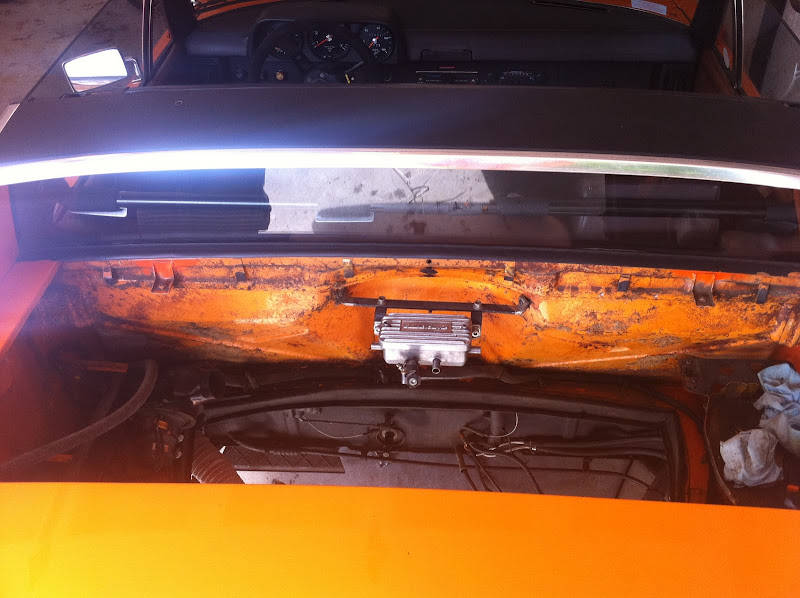
Here's the motor removed, with all the stock fuel injection installed: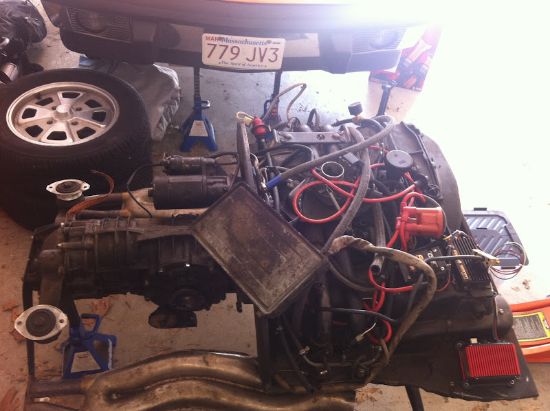
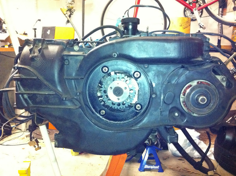
Here's the motor stripped of fuel injection and induction: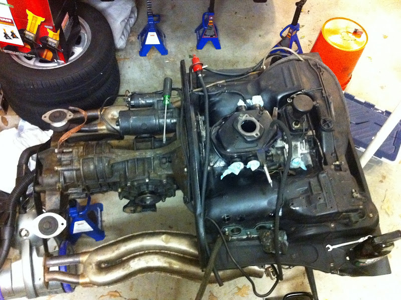
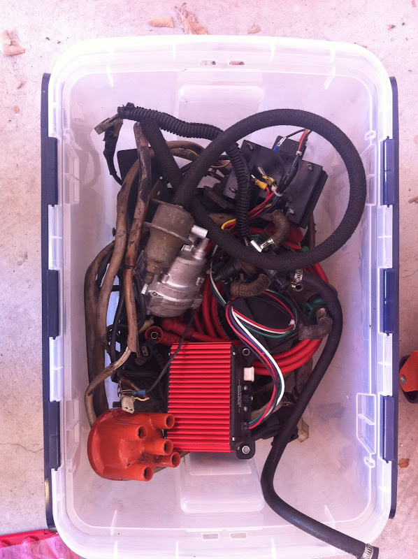
Here's the stock fuel injection wiring harness, computer, and components, ready to be retired. This stuff came off quickly and it felt good to be putting it out of service, like retiring a hall of fame pitcher that's past his prime or something.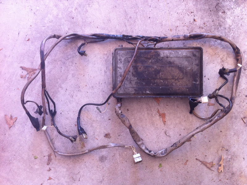
Here's my car, patiently waiting for its smarter powerplant: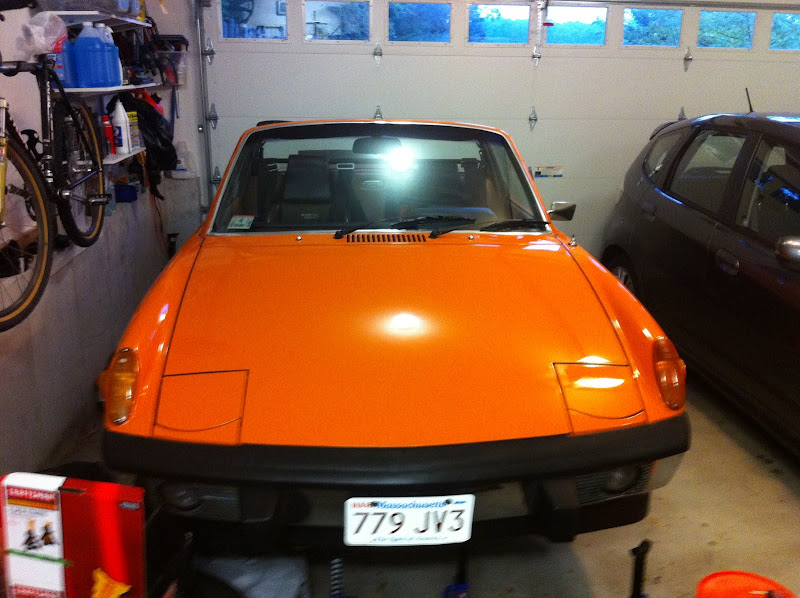
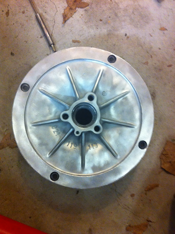
I'm correcting some items while I have the motor out, for example, I went to replace the throttle body gasket and couldn't....because when I took the TB off there was no gasket at all!! Lots of little things too, like missing fasteners in the engine tin and this flap missing from the impeller housing --> heater branch feed (that's Racer Chris' engine plate in the bottom of the pic):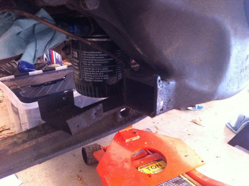
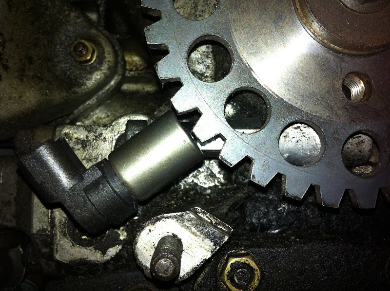
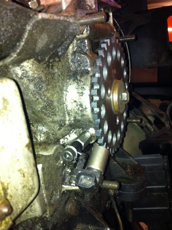
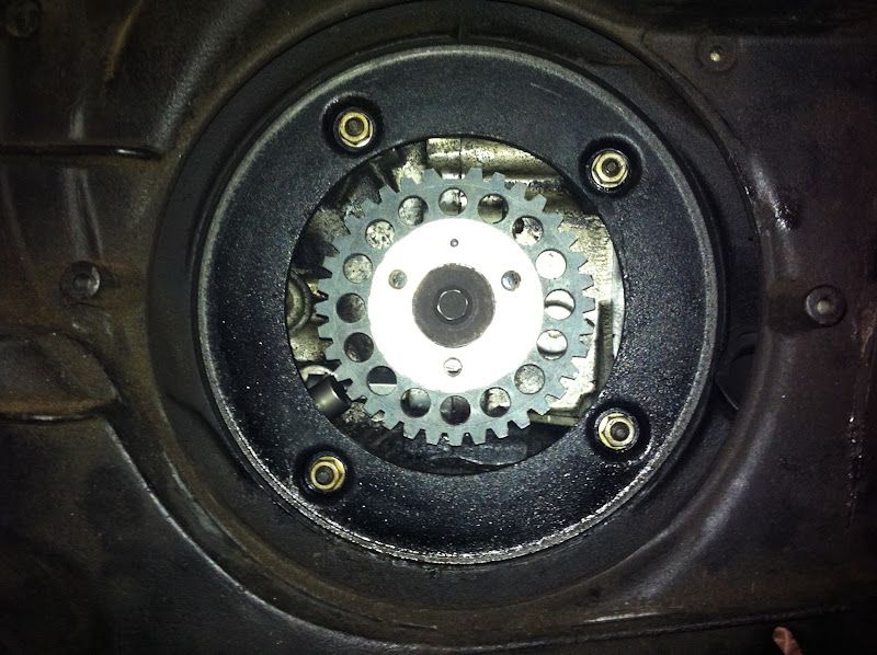
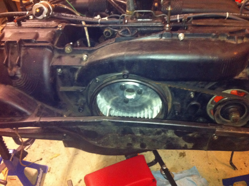
Next I removed the fan shroud and installed the pickup wheel and pickup. I documented my fan shroud removal adventures in another recent thread.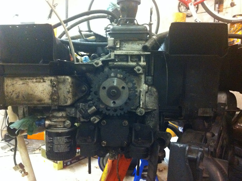
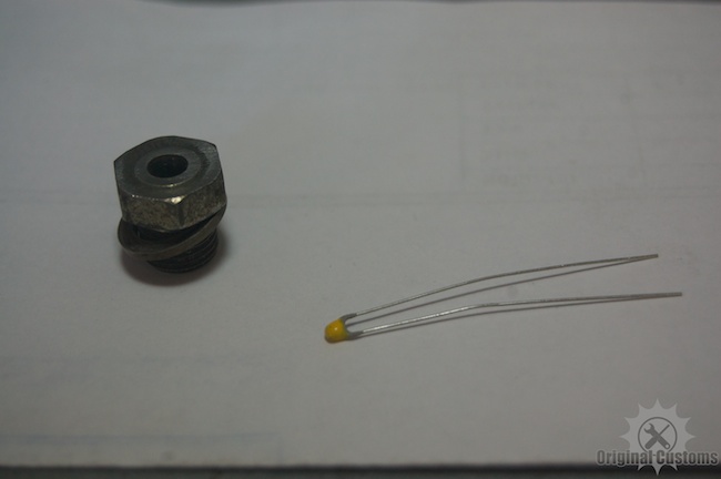
Here are some closeup detail shots of the trigger wheel and pickup, which show the gap (about 1mm) and angle. McMark supplied the special bracket which positions the pickup at that location. Note that this is 100% bolt-on -- no fabrication required.
Note that before the fan shroud goes back on, you need to connect the magnetic pickup to the wiring harness. I used a dremel to make a notch in the engine tin around the passenger side J tube, put in a grommet and ran the sensor cable through that. The pickup wire runs along the same basic path as the oil temp sensor wire.
That's it for now, my goal is to have this on the road by the end of October...
More pics to come as I make more progress!
Posted by: porscheless Sep 28 2011, 05:10 AM
Jeez Rich,
How bout a little degreaser in there... 
Not gonna say anything bout them galley plugs....
Very curious to how it's gonna work, especially with the butt dyno....
Joe
Posted by: rwilner Sep 28 2011, 05:29 AM
I know joe, a little embarassing...Believe it or not, that's after a single pass with simple green!
Deep cleaning is something I am saving for the rebuild. Just want to get this guy back on the road ASAP.
Posted by: type47 Sep 28 2011, 06:14 AM
subscribed!  I think McMark will get alot of orders for this, I'll be gettin' in the line, I know...
Posted by: sean_v8_914 Sep 28 2011, 07:47 AM
I winder how big we can go with the stock plenum, tb and intake runners
Posted by: rwilner Sep 28 2011, 08:16 AM

I winder how big we can go with the stock plenum, tb and intake runners
I think Mark told me 2270, which is the size I'm targeting for my eventual rebuild.
Posted by: ConeDodger Sep 28 2011, 08:20 AM
 McFuelInjection is going to really catch on... Are you going to go with my distributor replacement idea? Or are you going to stay stealth and have your distributor in place?
Attached image(s)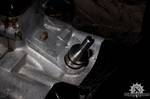
Posted by: ConeDodger Sep 28 2011, 08:24 AM
I winder how big we can go with the stock plenum, tb and intake runners
I think Mark told me 2270, which is the size I'm targeting for my eventual rebuild.
Sean isn't talking about displacement. He is wondering how big the air delivery to the displacement can be. I would guess it will depend on the sensors you choose to run your system on. Vacuum signal becomes undependable with big cams and overlap. Get too big with the runners and velocity may become an issue.
Posted by: rick 918-S Sep 28 2011, 08:30 AM
I winder how big we can go with the stock plenum, tb and intake runners
I think Mark told me 2270, which is the size I'm targeting for my eventual rebuild.
Sean isn't talking about displacement. He is wondering how big the air delivery to the displacement can be. I would guess it will depend on the sensors you choose to run your system on. Vacuum signal becomes undependable with big cams and overlap. Get too big with the runners and velocity may become an issue.
Ya, same old issue, maybe a flow bench is in order.
This is very cool!
Posted by: sean_v8_914 Sep 28 2011, 08:54 AM
my question was aimed at displacement. max rpm would be a factor. I was thinking about a 95mm x 80mm and keep the rpm below 6000.
wouldnt a MAF (instead of MAP) overcome the vacuum signature issue?
Posted by: ConeDodger Sep 28 2011, 09:11 AM
my question was aimed at displacement. max rpm would be a factor. I was thinking about a 95mm x 80mm and keep the rpm below 6000.
wouldnt a MAF (instead of MAP) overcome the vacuum signature issue?
many pardons...
The vacuum signal issue is two fold. I know you know this Sean but for others reading the thread the problem is getting rid of pulsations caused by the 4 different intake runners by using a common plenum and the low vacuum caused by performance cams. I think you're right Sean, a MAF would be an answer but I can't use one with SDS and I don't know if you can with Mega and Microsquirt.
With SDS the common solution is to operate with TPS or throttle position sensor as your fuel control. This is no better than carbs when it comes to altitude as you have to retune for altitude changes.
Sorry for the hijack. Your Microsquirt system will work. Mark has used it before...

Posted by: sean_v8_914 Sep 28 2011, 09:21 AM
Porsche used a vacuum plenum to get a usable vacuum signature
Attached image(s)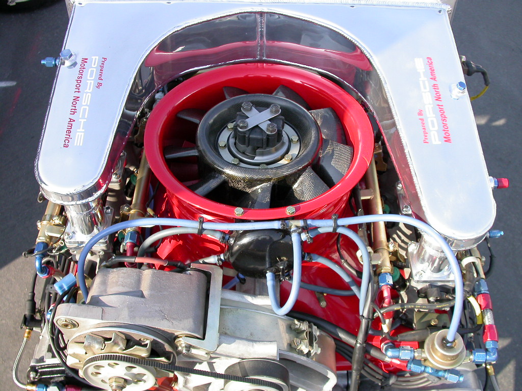
Posted by: sean_v8_914 Sep 28 2011, 09:27 AM
each throttle body is vac tapped to the plenum. this vac sig is used to modulate fuel pressure regulators under load
no MAFs in teh 80s yet
you can use a MAF and 2 air temps to calc density. solves altitude issue. (theoretical speculation since I have not done this config yet)
Posted by: sean_v8_914 Sep 28 2011, 09:32 AM
car porn hijack...
my next 914 engine 
Attached image(s)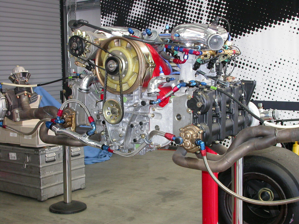
Posted by: rwilner Sep 28 2011, 09:35 AM
McFuelInjection is going to really catch on... Are you going to go with my distributor replacement idea? Or are you going to stay stealth and have your distributor in place?Distributor is out, never to be installed again (if all goes according to plan). Mark is making one of these plugs for me now... should have it installed next week.
Posted by: sean_v8_914 Sep 28 2011, 09:40 AM
Marks set up is super-clean. no dizzy, no vac lines webbing everywhere. I cant wait to see it
Posted by: tradisrad Sep 28 2011, 10:03 AM
I'll be watching.
Posted by: r_towle Sep 28 2011, 10:44 AM
I must agree I expected cleaner....lol
We joke in fun Rich...
Rich
Posted by: 904svo Sep 28 2011, 11:28 AM
I ran into problems trying to use MAP, the vacuum was not steady enough to tune the VE table. I had to pass a Two Speed Idle test for inspection. I then try to use TPS instead, this also failed inspection test. The TPS/VE table did not know the difference between no-load and load. I then went to MAF using a Ford MAF sensor,
the car now passes inspection as the MAF measures the air flow which is difference
between load and no-load. The engine also runs great now it idles at 600 RPM's and is smooth as silk.
All these changes were made on a stock 1.7 ltr engine using Megasquirt running MS1-extra software.
Posted by: 914_teener Sep 28 2011, 08:30 PM
....ok if this works well....I'm headed North to McMark's.
![popcorn[1].gif](style_emoticons/default/popcorn[1].gif)
Posted by: rwilner Sep 29 2011, 08:02 PM
Made some more progress tonight.
Not MS install related directly, but while the engine is out I decided to install an oil pressure sender. I sourced the stainless hose from a paintball shop per Rich Towle's suggestion -- it had the right threads, right length, and was cheap (1/8" NPT). The tee and clamp i got from mcmaster, along with a bunch of fasteners.
VDO makes a unit that contains both a pressure sender and pressure switch, but the switch in that unit is set to trigger @ 7psi. The stock switch is set to trigger @ 2psi, so I wanted to retain the stock unit. 7psi is about what the oil pressure is at idle, and seeing the oil pressure light flicker at idle would just make me constantly nervous.
The stainless hose is nice because it provides a solid connection to ground for both the switch and the sender.
Installing that hose in the block was super easy with the fan shroud off. With the fan shroud on, it's probably still possible, but quite difficult to access -- even my flex head box wrench wouldn't fit through the engine tin. A crow's foot might do it.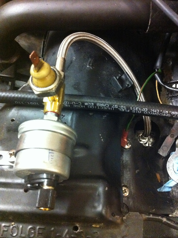
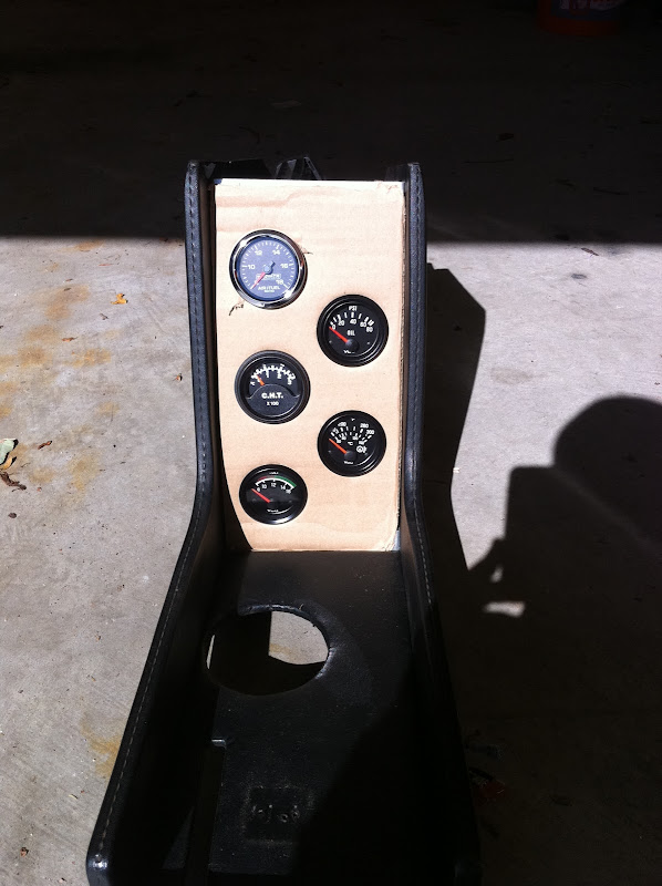
Here are my new gauges. My center console will contain (from bottom to top) a new voltmeter, oil temp, oil pressure, cyl head temp, and AFR. The AFR gauge is still in transit.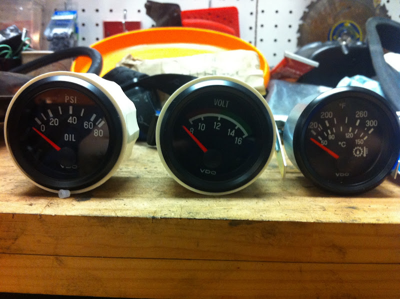
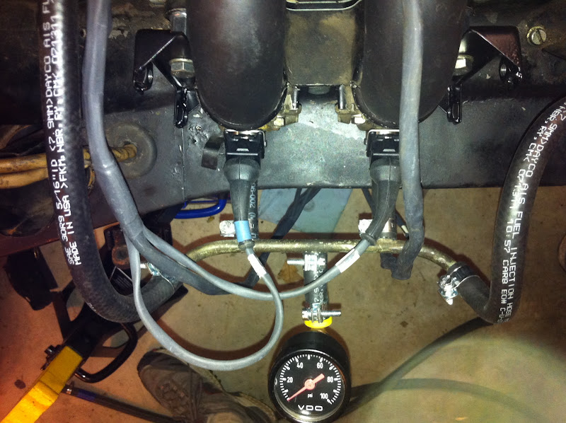
Most of the wiring harness is installed. I'm still waiting for some fasteners from McMaster to attach the ignition coils, should be here tomorrow. i'm using the port on the DS fuel rail that used to feed the cold start valve to feed a fuel pressure gauge.
I also bought Racer Chris' fuel hose kit with the flat clamps and installed them.
Here are the custom brackets McMark made to mount the ignition coils. They mount to the stock intake manifold studs using coupling nuts. Pretty slick!
I also replaced the motor mounts and installed the engine bar, fan shroud, impeller, belt and heat parts.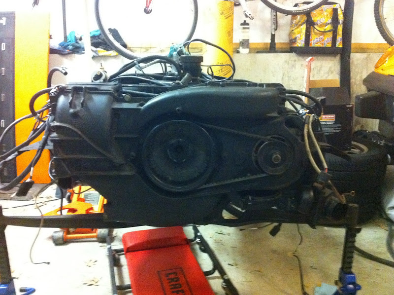
That's it for now, I'll pick it up again over the weekend.
Posted by: championgt1 Sep 29 2011, 09:05 PM
Nice work. This is cool!
Posted by: McMark Oct 2 2011, 06:14 PM
Going in the mail tomorrow... 
Attached image(s)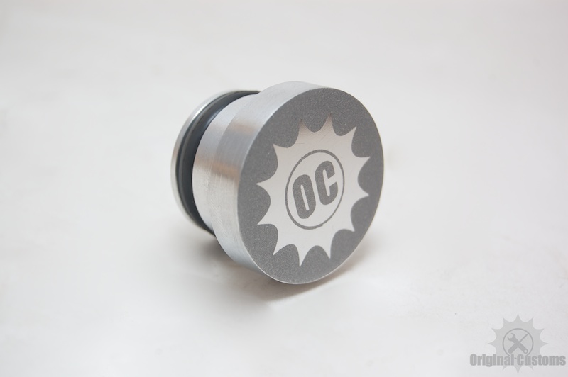
Posted by: rwilner Oct 2 2011, 06:40 PM
Going in the mail tomorrow...
Can't wait!
Mark -- i found http://www.innovatemotorsports.com/forums/showthread.php?p=74750 talking about how to wire up the innovate G5 gauge, looks straightforward
Posted by: rwilner Oct 2 2011, 08:00 PM
Some progress this weekend.
I got the ignition coils mounted and the rest of the wiring harness installed. Here's what the ignition coils look like installed on Mark's custom brackets: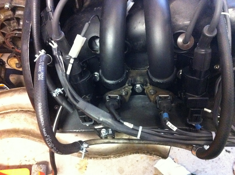
Here's a closeup of the coil install, notice where the ground pickup is -- right on the bracket: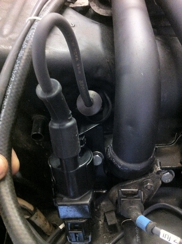
Here's the wiring harness all dressed in. I also replaced all the engine tin and fan shroud screws (and in many cases, installed screws that were missing altogether) with stainless socket head cap screws. That blue paper towel in the distributor cavity will soon be replaced with a sweet OC plug!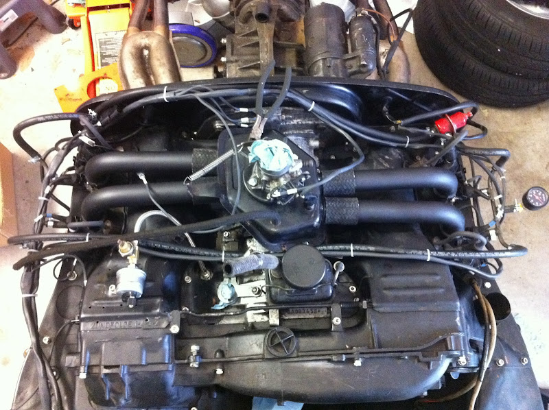
I also mounted the MAP sensor and O2 sensor brain the factory location for the MPS. Per Mark's suggestion, to mount the O2 brain, I reformed a stainless P clamp to the profile of the O2 brain and lined the inside of the clamp with gasket material. My other idea was to get another air cleaner mount and attach it to the passenger side intake runners, and then mount the O2 brain to that. I like this better.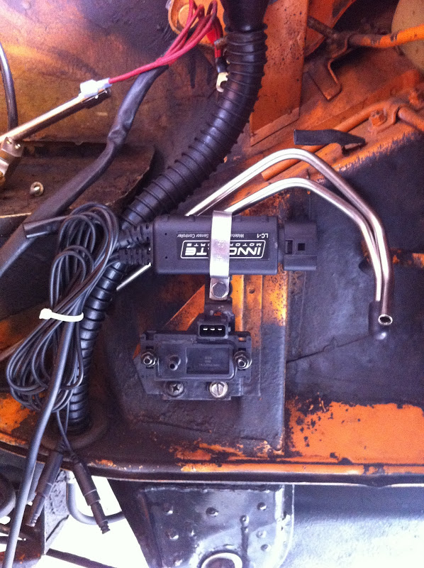
I noticed a small hole in the back of the MAP sensor. I thought this might have been the sensor's atmosphere reference (why else would there be a hole in the housing?), so I drilled a hole in the bracket to provide access -- check out the second hole from the right:
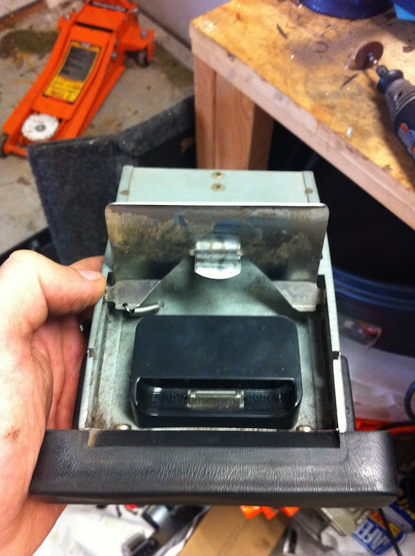
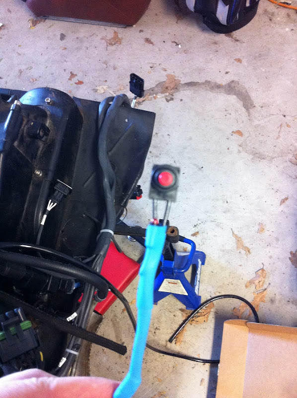
I'm also modifying the ash tray to become an iphone mount. Made some progress on that today also: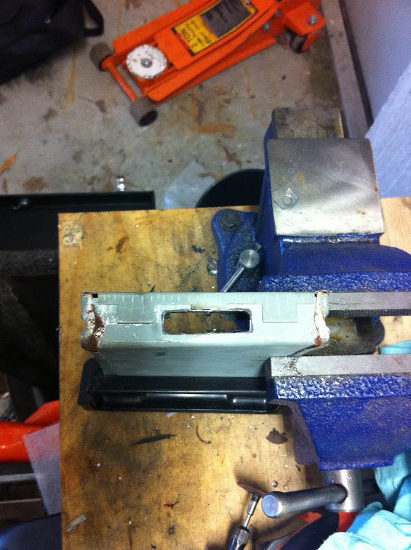
I also got the interior disassembled to prepare for the gauge install, and designed my new gauge panel face. The small hole is for a toggle switch that turns my audio amplifier on and off: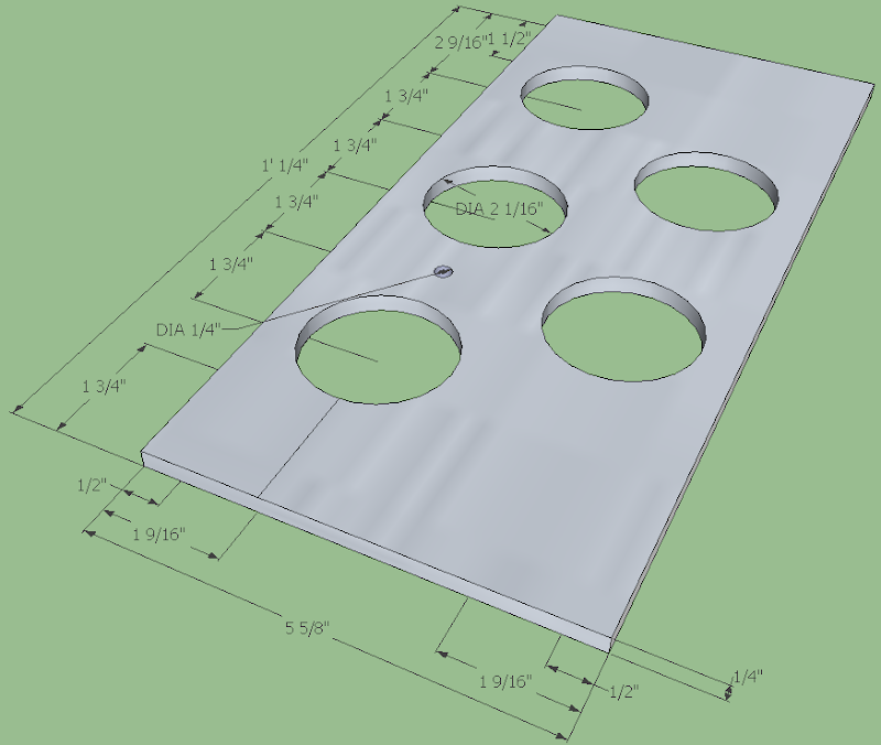
That's it for now. Tomorrow I'm stopping by http://www.youdoitelectronics.com/ on my way home to get what I need to make up my new gauge wiring harness.
Posted by: moparrob Oct 2 2011, 08:49 PM
car porn hijack...
my next 914 engine
Sean, that is nice. What is it though?
Posted by: kg6dxn Oct 2 2011, 08:57 PM
Very nice! You will enjoy it.
Posted by: 76-914 Oct 2 2011, 09:35 PM
Rich, is the top as viewed or is the panel upside down? That 1/2" border isn't enough to clear the top bracket/brace.
Posted by: 914_teener Oct 2 2011, 11:54 PM
What AFR gauge did you buy...and where are you going to mount it?
Thanks for this....and cool little distributor block off Mark.
Posted by: rwilner Oct 3 2011, 05:13 AM
Rich, is the top as viewed or is the panel upside down? That 1/2" border isn't enough to clear the top bracket/brace.
It may be tough to see in the pic, but that is a 1.5" border around the top.
Posted by: type47 Oct 3 2011, 05:31 AM
Don't forget that gasket/grommet for the oil pressure hose where it goes through the tin...
I think it's 021.119.957 oil pressure boot. I found it at busdepot.com but NLA on pelican.
Posted by: rwilner Oct 3 2011, 06:12 AM
Don't forget that gasket/grommet for the oil pressure hose where it goes through the tin...
I think it's 021.119.957 oil pressure boot. I found it at busdepot.com but NLA on pelican.
http://busdepot.com/details.jsp?partnumber=021119957
Thanks Jim!!

Posted by: r_towle Oct 5 2011, 12:41 PM
Third page.
Slacker
Rich
Posted by: rwilner Oct 5 2011, 12:47 PM
Third page.
Slacker
Rich
Ha.
I did do some work this week, I had to build my own wiring harness for the new gauge cluster. I have a buddy making up the face out of 1/8" stainless...a long story, he owed me a favor and that's what he had.
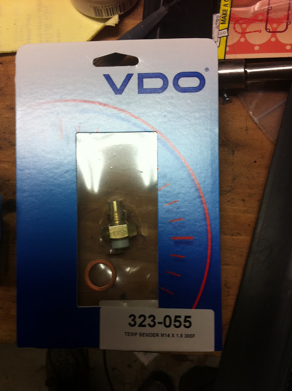
I also installed the new temp sender. Let's hope that weird combo of seals in the taco plate holds oil!
New harnesses are on the way from Jeff Bowlsby for my alternator and ignition. With Mark's new FI harness, I could't put the 40 y/o tired ones back in the car in good conscience.
Will post some pics tonight
Posted by: rwilner Oct 10 2011, 09:29 PM
Progress!
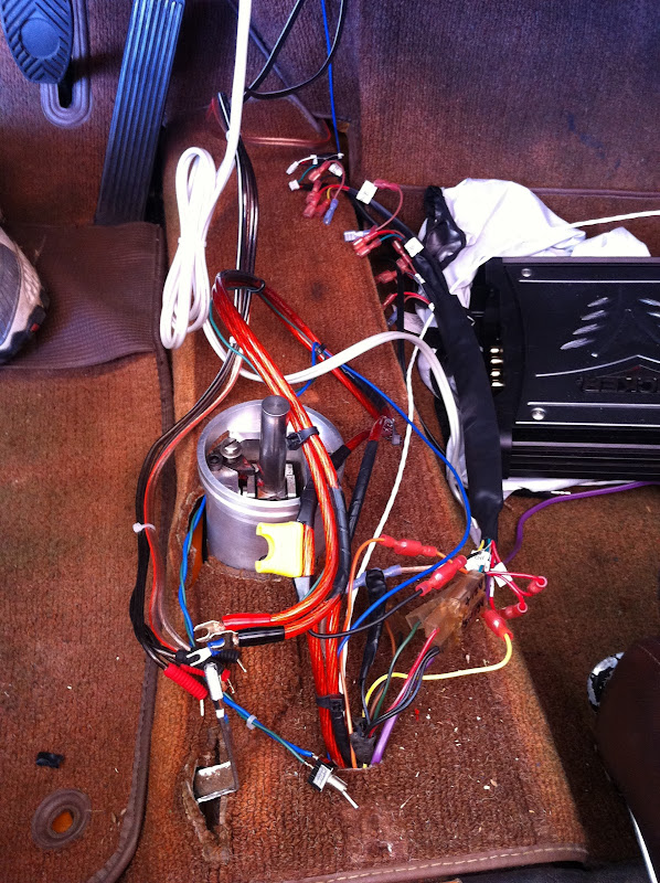
Got the interior pulled apart to get the new wires run for the gauges and iphone integration.
I mocked up the gauge panel in cardboard to build the wiring harness while the panel is being fabbed at the metal shop. I test-fit the gauges with the amplifier installed in the center console -- it just fit! I'd rather be lucky than smart...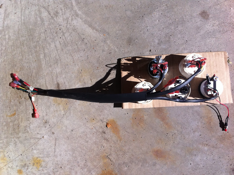
phew!!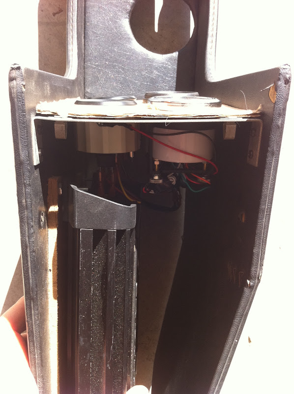
I installed a new grounding point, then ran the new wires for the oil pressure gauge, AFR gauge, and serial communications to the microsquirt. Then the center console went back in.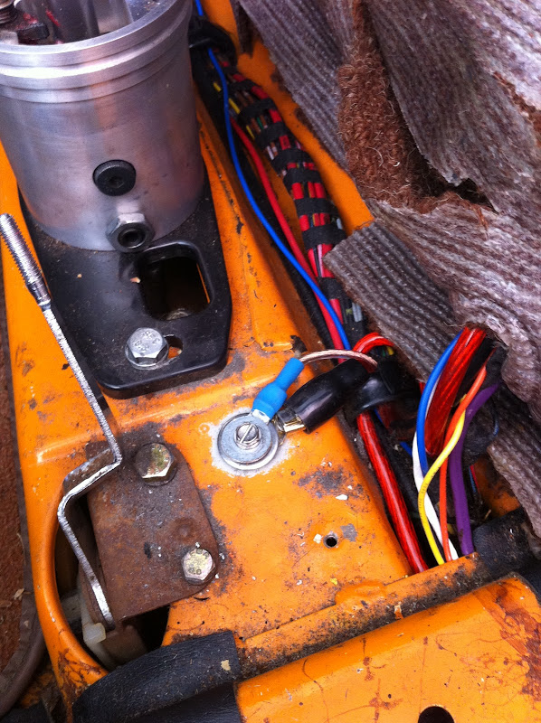
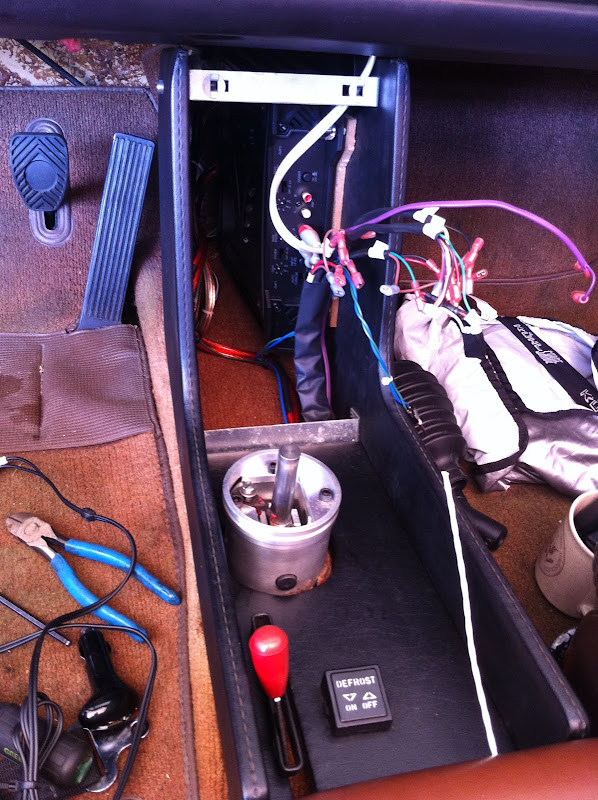
I also replaced my ignition harness and alternator harness with Bowlsby ones, plus i replaced my starter-to-battery cable with a new one. I had the 4 gauge cable lying around and the old one looked crusty.
old and new ignition harness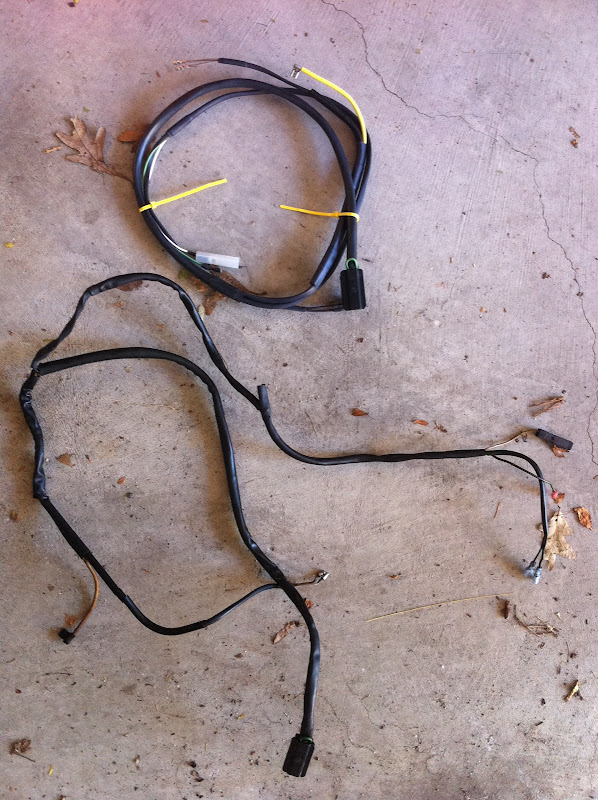
old and new alternator harness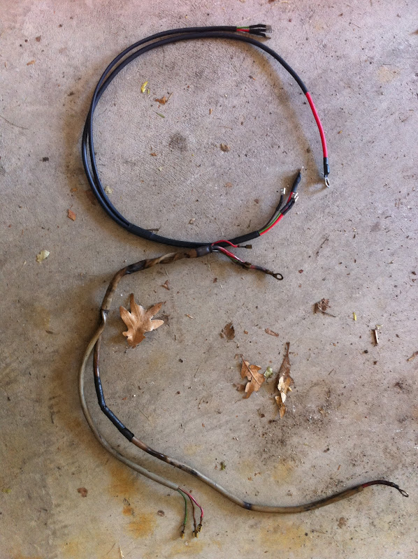
new starter cable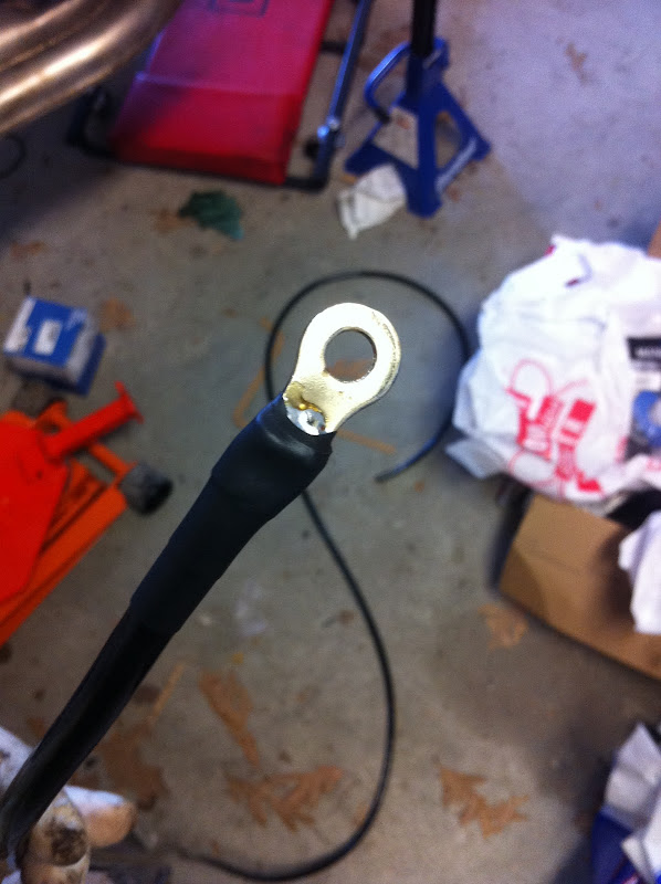
new cabling attached to the starter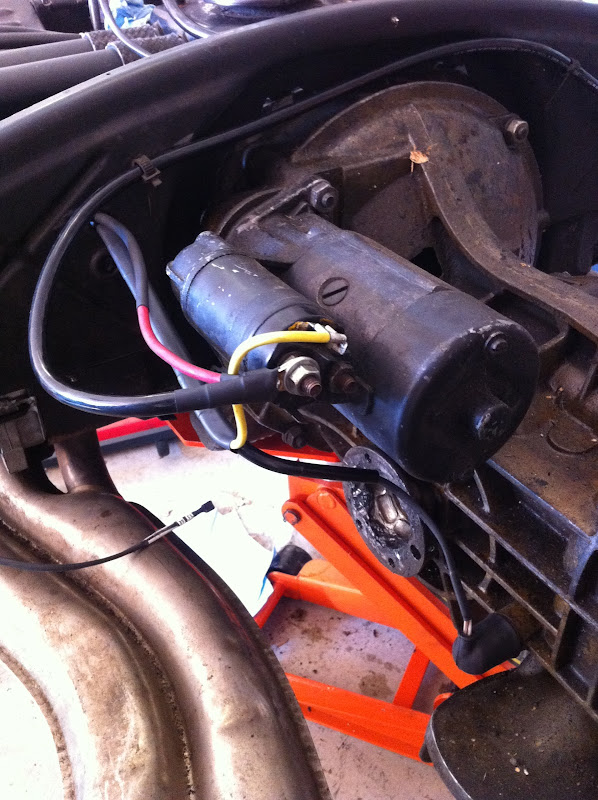
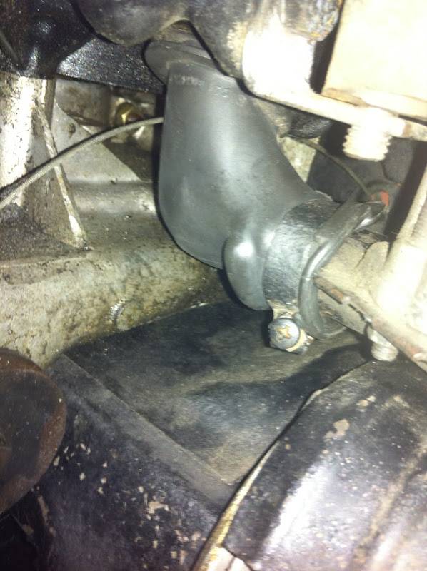
When I took the alternator off to install the harness, I noticed my boot was a shadow of its former self  . Fortunately Mark Heard had one in good shape to send me
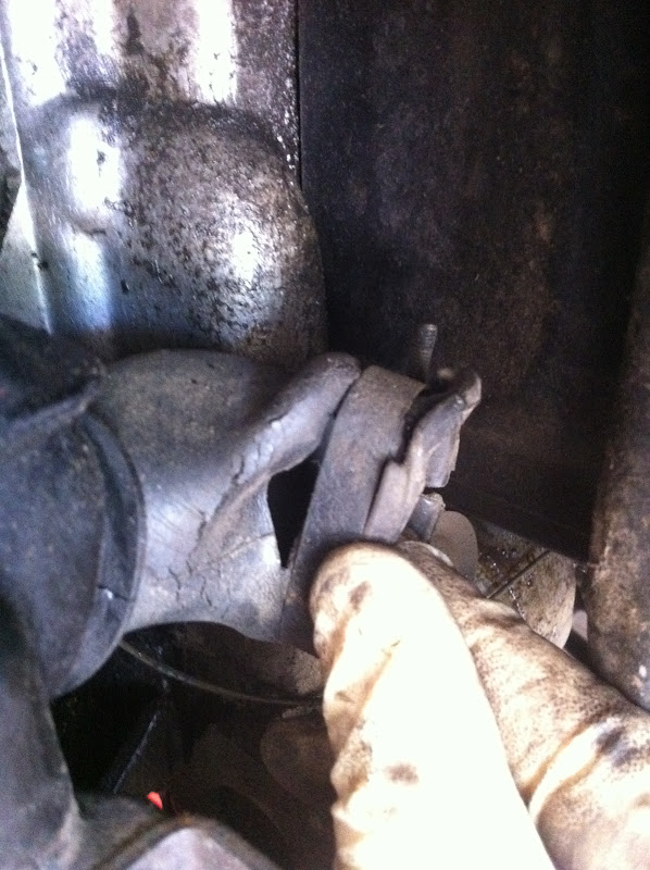
That's it for now -- getting close to done!
Posted by: rdauenhauer Oct 10 2011, 09:33 PM
Looks like you already had to mod the base plate on your console to fit the Rennshifter?
Posted by: rwilner Oct 10 2011, 09:35 PM
Look like you already had to mod the base plate on your console to fit the Rennshifter?
Yep, I had to make it a little bit larger.
Posted by: McMark Oct 10 2011, 09:39 PM
Just thought of something, check the coil ground, as installed, by using an ohm meter between the showing portion of the ring connector and the case. Just to be on the safe side.
Posted by: rwilner Oct 10 2011, 09:42 PM
Just thought of something, check the coil ground, as installed, by using an ohm meter between the showing portion of the ring connector and the case. Just to be on the safe side.
I will do tomorrow and report back
Posted by: rwilner Oct 10 2011, 09:53 PM
What AFR gauge did you buy...and where are you going to mount it?
Just saw this question
I got thehttp://www.innovatemotorsports.com/products/g5_gauge.php -- $70 with shipping via amazon. I liked this gauge because it matches the style of the VDO gauges. I'm mounting it in my center console, you can see it mocked up in cardboard in the thread above.
Posted by: 76-914 Oct 10 2011, 09:58 PM
Looking good Rich. I had the same staggered 3/2 set up but went to a staggered 2/3 when I found the steering wheel blocked my view of the upper left gage when staggered 3/2. I don't know what it will be for you but sit in the seat and check it out. Measure twice cut once.
Posted by: rwilner Oct 11 2011, 03:15 PM
Just thought of something, check the coil ground, as installed, by using an ohm meter between the showing portion of the ring connector and the case. Just to be on the safe side.
I will do tomorrow and report back
Mark
The grounding ring terminals of all four ignition coils ring out to the case. I chose the multi-prong ground spade terminal on the engine block as my grounding test point on the case.
Posted by: McMark Oct 11 2011, 03:59 PM
I'm assuming 'ring out' indicates zero resistance. 
In which case, AWESOME! 
Posted by: rwilner Oct 11 2011, 06:21 PM
I'm assuming 'ring out' indicates zero resistance.
In which case, AWESOME!
yep
Posted by: rwilner Oct 21 2011, 06:52 AM
Just thought I'd post a quick update...
All the work I had planned (and I a bunch I didn't have planned) is done and the engine is going back in on saturday. I'll be posting pics after the engine is back in. If all goes well I should be able to fire my 2.0 version 2.0 engine this weekend! 
Posted by: r_towle Oct 21 2011, 07:02 AM
sweet....
Rich
Posted by: sean_v8_914 Oct 21 2011, 07:17 AM
that's a good price. what did you pay for the LC-1 wide band controller?
Posted by: rwilner Oct 21 2011, 07:40 AM
that's a good price. what did you pay for the LC-1 wide band controller?
Sean,
I didn't purchase this separately, it was buried in McMark's FI package cost.
Posted by: 914_teener Oct 21 2011, 11:18 AM
that's a good price. what did you pay for the LC-1 wide band controller?
Sean,
I didn't purchase this separately, it was buried in McMark's FI package cost.
This looks like a great set up......keep us posted.

Posted by: rwilner Oct 22 2011, 07:28 PM
I got my engine back in the car. Some questions for the experts:
1) there's a gap between the engine tin and the new seals I installed. Did I install the seals upside down?
2) If so, can I remove, flip, and reinstall the seals with the engine in the car or do I have to remove the engine again to do this?
See pics...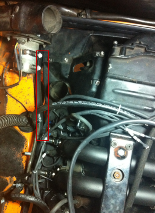
Posted by: McMark Oct 22 2011, 10:34 PM
The seal should hang down, and there should be a small upturned section. That upturn hooks under the tin. Try that...
Posted by: rwilner Oct 23 2011, 07:17 AM
The seal should hang down, and there should be a small upturned section. That upturn hooks under the tin. Try that...
i love doing things twice!
looks like the engine is coming out and in again today...

Posted by: rwilner Oct 23 2011, 09:00 PM
Had a fairly productive weekend.
I received Tom's raised fuse block and installed it. It's a raised 4 position fuse block that protects the 4 hot wires connecting to the battery. Installation was a snap while the engine was out, although installing with the engine in place wouldn't be very difficult either.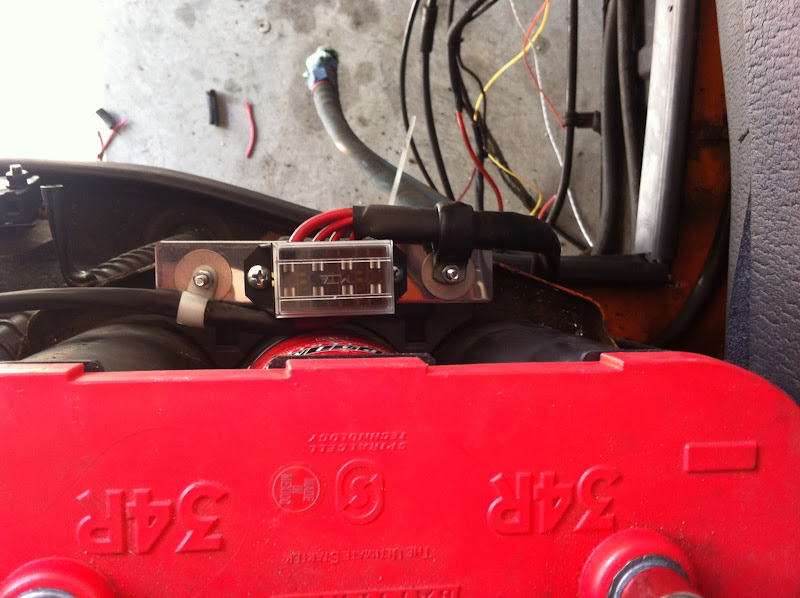
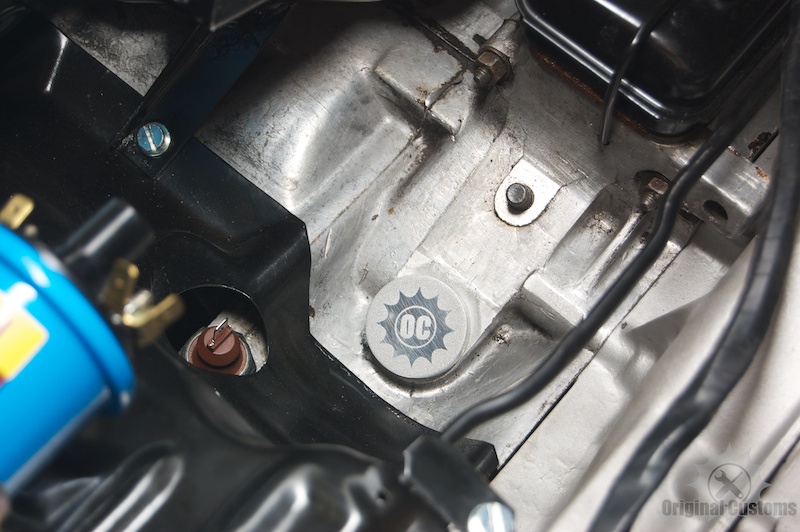
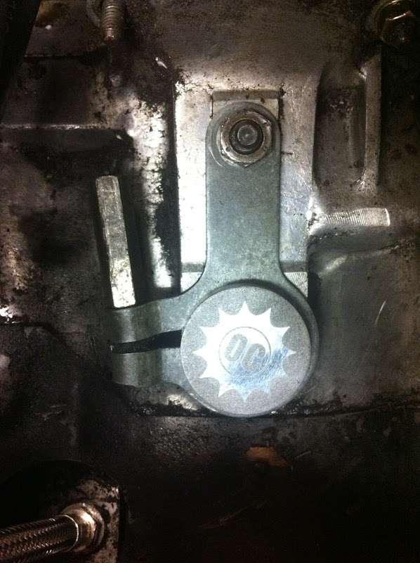
After I cleaned up a bunch of gunk I found my GA engine number! Also, check out this SWEET plug McMark supplied to clean up the distributor channel. Style and function!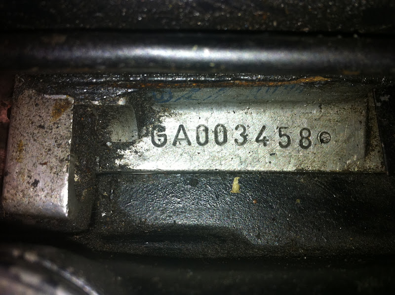
My engine impeller was missing 1 fin, so I purchased this very nice one from Mark Heard and popped it in place. Mark also gave me an alternator cooling boot in great shape, which replaced the liquefied one shown earlier in this thread.
I installed a new engine soundpad from AppBiz (highly recommended) and new engine bay seals from Mikey914. I recommend that unlike me, you do not install the engine seals upside down the first time around... 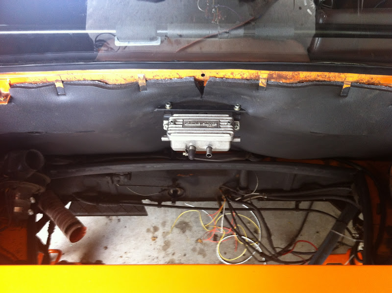
I drilled a hole in the engine tin to run the wires for the O2 brain. I had to determ and reterm the weatherpack connector to feed the wire through the hole, which was a no-brainer. The O2 brain will mount to one of the transmission mounts. I had to relocate the brain because the O2 sensor wire was not long enough and no extension was available or recommended by the manufacturer. I also built a little harness to calibrate the O2 sensor, which is required every 10k miles or once per year.
Now it was time to lure a buddy to my house with a six pack and put the engine back in the car.
Not quite ready to fire the engine, but with some effort this week I should get there by the weekend -- just reconnecting stuff now!
Posted by: radmelon Nov 13 2011, 11:33 AM
Rich- where did you place the O2 sensor bung? Did you weld it into the exhaust manifold (F tube) or further down after the heat exchanger? Great pictures by the way. Very helpful!
Posted by: rwilner Nov 13 2011, 07:07 PM
Rich- where did you place the O2 sensor bung? Did you weld it into the exhaust manifold (F tube) or further down after the heat exchanger? Great pictures by the way. Very helpful!
hey rad...
 (or at least, welcome to posting)
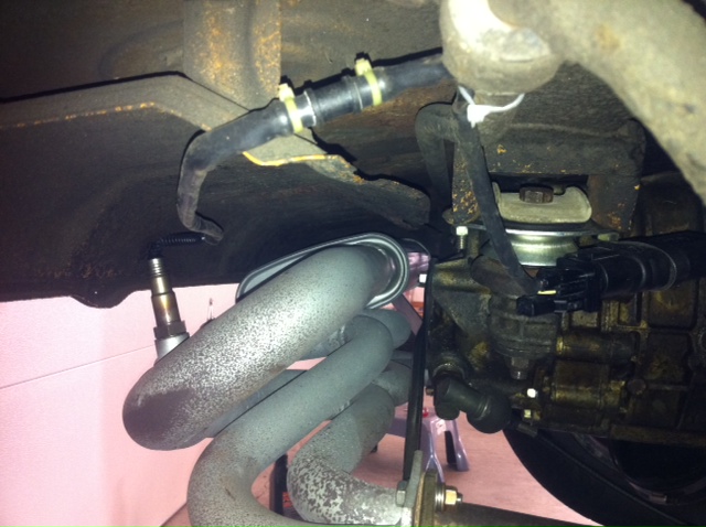
I placed the O2 bung at the "collector" portion of my bursch muffler, right before the muffler portion. Here are some pics:
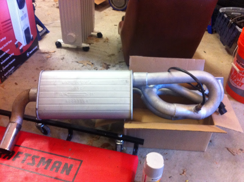
I coated the weld and bung in hi temp paint to inhibit the rust some:

The guy who welded in the bung is named Maurizio. His shop is within walking distance from my house and he always has a bunch of cool old cars parked in and around his shop. Whenever the sun is shining he drives this sweet 356!

Over the last 2 weeks, Mark and I have been working on refining the wiring harness some and getting the settings in the microsquirt controller just right. So finally, this weekend, Rich Towle came over and we got the car started!
In Mark's words, I'm now in "tuning land" and hope to be
 by next weekend!
For any future purchasers of Mark's FI kit -- after I get the microsquirt settings dialed in, I will post the MSQ (settings file) in this thread so you can download it, load it up, turn the key and be 75% of the way to a tuned car.
Posted by: 914_teener Nov 14 2011, 12:38 AM
Thanks for the update. I was wondering what happened to this install and thread.
Posted by: rwilner Nov 18 2011, 08:50 AM
More Progress...
I pulled a plug after my initial tuning efforts. Think it was running a bit rich?!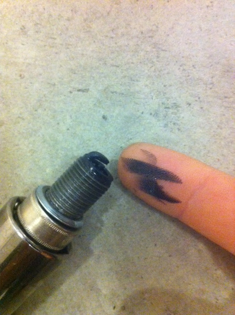
So I began to investigate and found several issues.
Issue 1: My intake air temp sensor was reading as 0 degrees F. This is an obvious cause of rich running.
The MS calculates fuel delivery using a volumetric efficiency (VE) table, where the amount of fuel injected is calculated based on the mass of air being sucked in via the intake. If I had a mass airflow sensor, that would be measured directly. Instead of a MAF sensor, I am using a MAP (pressure) sensor and the intake air temp sensor. The MS uses these two sensors and calculates the air mass using the ideal gas law. Well, 0 deg F air is wicked dense which means lots of fuel.
It was just dumping fuel into the combustion chamber.
I fixed this by RTFM and discovering the MS has an internal biasing resistance of 2490 ohms. I also characterized my IAT sensor in boiling water, freezing water, and at room temp. The results are shown in the attached screenshot: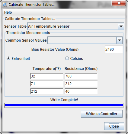
Issue 2: The CHT was reading as 0 degrees F. The stock CHT grounds against the engine block (like a spark plug). The MS has the sensor ground separated from the dirty engine block ground. Well, that resulted in the CHT reading as an open circuit, since the resistance of the CHT had no ground reference. I was left with 3 options:
- Tie the sensor ground to the engine ground. This was workable but not ideal because it would introduce noise into all the sensor inputs (TPS, MAP, IAT, CHT, O2). How much noise? Who knows, but if it can be avoided...
- Find an NTC thermistor with an M10 thread. I think they sell these at the same place you can buy unicorns.
- Drill out a stock CHT and mount (epoxy) a 2-wire NTC thermistor in that body, essentially turning the stock CHT into a http://www.pyromation.com/Products/Thermowells.aspx. The epoxy is thermally conductive but not electrically conductive. This was the best solution.

This should arrive today or tomorrow. I will characterize this sensor the same as the IAT, program it in and we should be in business.
I also had to program the LC1 (oxygen sensor brain) to scale properly.
Lesson learned: make sure every sensor is reading correctly and accurately before you even turn the key to start tuning. Seems obvious, but in the complication of getting the engine started, sometimes the obvious can be overlooked.
I have saturday afternoon (55 deg and sunny) reserved for getting this thing on the road and driving, we'll see if I can make it happen!
Posted by: ConeDodger Nov 18 2011, 09:06 AM
Rich, I'm watching this with great interest. Marks's EFI system using the Microsquirt ECU is actually a little 'smarter' than SDS. Mine works, but it could be more accurate and tunable.
Posted by: draganc Nov 18 2011, 09:14 AM
Great work/job!!
And I'm gald you haven't lost your humor:
"...Find an NTC thermistor with an M10 thread. I think they sell these at the same place you can buy unicorns..."
Posted by: zymurgist Nov 18 2011, 09:19 AM

I nominate this thread for "classic" status.
Posted by: rwilner Nov 18 2011, 09:58 AM
I nominate this thread for "classic" status.
thanks...maybe we should wait until I'm on the road and driving...
It's really fun to learn about fuel injection. There is so much happening just to inject the right amount of fuel and spark at the right time.
Also -- Mark has been really fun and enjoyable to work with. If I'm lucky, he's only doing 2 other things when I call him with a question...usually it's more like 4 or 5
The ultimate goal of this effort is to have a modern, turn-key, bolt-on replacement solution for the factory FI system. It's just one more option for us to keep our cars on the road and running great.
I'm really close now!
Posted by: rwilner Nov 18 2011, 10:25 AM
Rich, I'm watching this with great interest. Marks's EFI system using the Microsquirt ECU is actually a little 'smarter' than SDS. Mine works, but it could be more accurate and tunable.
Hey Rob
MS is definitely more tunable, but it's also more complicated. There is the classic tradeoff.
Is the extra tunability worth the extra complication? That's the big question, and unless you're trying to squeeze every ounce of power and efficiency out of the engine, it might not make a huge difference. If you're happy with your car's performance (and it certainly sounds like you are), then SDS was the right choice for you.
I chose MS because it's what Mark engineered his system around and it required zero fabrication and modification of the engine bay / body / stock wiring. Also, the laptop-style tuning interface with realtime displays and datalogging really appeal to the way I think and understand systems like this.
A perfect example: the trigger wheel wasn't reading RPM initially. Because the MS is so flexible, I was able to load diagnostic firmware onto the controller and discover the root cause of the problem. Because the MS is so complicated, it turned out that software configuration was the root cause of the problem
Like carbs vs. FI or 4 vs. 6 or X vs Y, there is never (or rarely) a right answer...only a best answer depending on your goals, skills, and expectations.
By the way -- your ITB setup looks awesome and it's great to see PEFI on a high performance big 4. When I build my big 4, I am considering moving to ITBs.
Posted by: type47 Feb 5 2012, 09:08 AM
Updates?
Posted by: Racer Chris Feb 5 2012, 09:38 AM
Updates?
The day after Rich got the EFI operating correctly, a couple weeks ago, his wife had their first baby.
Posted by: rwilner Feb 8 2012, 12:18 PM
The day after Rich got the EFI operating correctly, a couple weeks ago, his wife had their first baby.
As Chris said...
Jeffrey Linus Wilner born 1/25 @ 4:32 pm. Everyone's happy and healthy. He has a really strong grip already...maybe strong enough for a torque wrench? He here is passed out after I gave him a lecture on port injection vs. direct injection:

Back to our regularly scheduled programming!
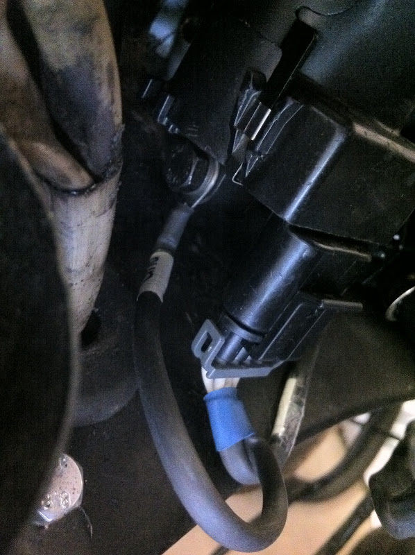
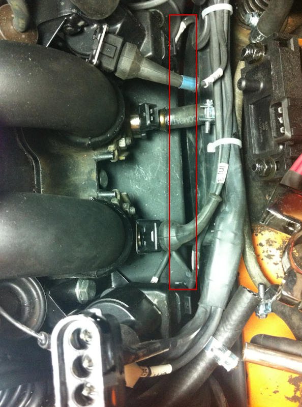
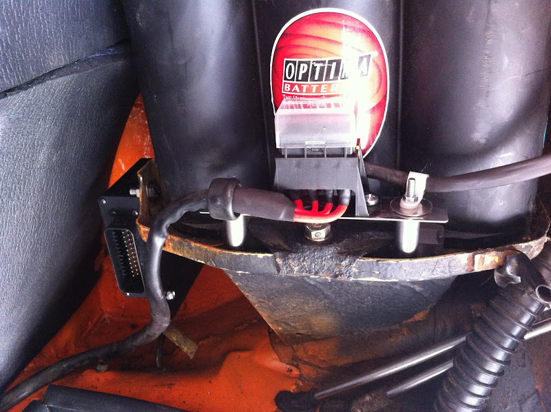
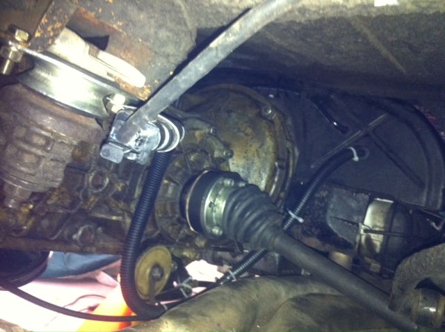
Here's a picture of the oxygen sensor and oxygen sensor brain mounting. The brain --> ECU cable is routed down to the clutch cable wheel plate -- it looks like it's touching the heat exchanger in the photo, but it clears just fine. The brain is secured to one of the transmission mount bolts using a reformed P clamp. I used a longer bolt in this location to receive the second nut.
I am very happy to report that the car is running 100% on all 4 cylinders -- I'm using it now for (seemingly daily) diaper runs. For a long time I was having an issue where the car was running great on cylinders 1 and 3, but ran like crap once I plugged in 2 and 4. Many hours of troubleshooting later, we discovered that there is a parameter in the software called "offset / advance for output #2" that I had set to 180 degrees...well...the system automatically advanced output #2 180 degrees based on the configuration (4 cyl / even fire / wasted spark), so I was actually advancing the second output 360 degrees by setting that parameter to 180. Not good. After I set that parameter to 0, the car ran like a champ.
Tonight I'll post up my .msq file so that any others planning a mega/microsquirt conversion can use it as a starting point. Anyone purchasing McMark's setup should be able to use this as a turn-key file to get their car started, running, and driving. You will definitely have to make tuning adjustments for your motor no matter what you're running, although if you have a stock GA 2.0L, this file should be 80% or better to a final tune.
Note: I developed this tuning file using the V2 microsquirt enclosure. DIYEFI is now selling the V3 enclosure which has a slightly different pinout and form factor; however, I have tested this file with the V3 enclosure and it works great. I'd actually recommend the V2 enclosure over the V3 if you can find one because the V2 enclosure is extruded aluminum and the V3 is molded plastic.
I still have some final bugs to work out (tach not working with the MS output, O2 reading is a bit wacky, oil temp gauge not reading, need to replace ignition switch), but the car starts right up and drives awesome.
Please feel free to post any questions about this setup in this thread.
Posted by: rdauenhauer Feb 8 2012, 01:11 PM
Good head of hair on the boy, Congrtats!
Posted by: rwilner Feb 23 2012, 09:51 AM
Slowly working out my issues as time allows...
My mom and dad were in town, so while my mom was on baby duty, my dad and I got some work done on the car.
I replaced the sealed beam tungsten lenses with the H4 kit from pelican and also replaced the ignition switch. But the bigger win was getting a working tach.
There is definitely a way to get the microsquirt to work with the stock tach. But, time is at a premium with me these days so experimenting with a charge-pump circuit is not in the cards.
I selected an aftermarket tach based on a suggestion from another member here -- an equus 8080. PRetty short money from summit ($110 I think.) This is the same company that makes the special timing light that works correctly with my new wasted spark DIS. It is also the only aftermarket tach I've found that has an inductive spark plug pickup option! Very cool. Turns out I didn't need that because this thing picked up the signal from the microsquirt Tach output like a champ.
I relocated the turn signal (green LEDs) and hi beam (amber LED) indicators to the gauge bezel. Also shot the gauge bezel with a fresh coat of enamel.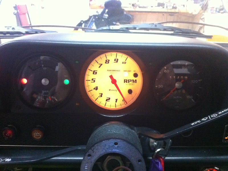
Only remaining issues are my oil temp gauge and O2 sensor readings. I keep forgetting to post the .msq...
Posted by: bohalrantipol Feb 24 2012, 01:56 PM
Man this is good info! thanks for putting this up! I am in the process of assembling a system very similar to yours. Please do put up the .msq!
Thanks again!
Please note all of the exclamations!!!
Posted by: falconfp2001 Mar 6 2012, 02:41 PM
Slowly working out my issues as time allows...
My mom and dad were in town, so while my mom was on baby duty, my dad and I got some work done on the car.
I replaced the sealed beam tungsten lenses with the H4 kit from pelican and also replaced the ignition switch. But the bigger win was getting a working tach.
There is definitely a way to get the microsquirt to work with the stock tach. But, time is at a premium with me these days so experimenting with a charge-pump circuit is not in the cards.
I selected an aftermarket tach based on a suggestion from another member here -- an equus 8080. PRetty short money from summit ($110 I think.) This is the same company that makes the special timing light that works correctly with my new wasted spark DIS. It is also the only aftermarket tach I've found that has an inductive spark plug pickup option! Very cool. Turns out I didn't need that because this thing picked up the signal from the microsquirt Tach output like a champ.
I relocated the turn signal (green LEDs) and hi beam (amber LED) indicators to the gauge bezel. Also shot the gauge bezel with a fresh coat of enamel.
Only remaining issues are my oil temp gauge and O2 sensor readings. I keep forgetting to post the .msq...
Where are you getting the tack signal for your gauge? I can't find the output from the DB37 for a tack signal but they say that you can take it from the (-) pole of the coil packs and then run it through a converter to reduce the signal by half to use it with the stock gauge.
Posted by: rwilner Mar 6 2012, 03:02 PM
Where are you getting the tack signal for your gauge? I can't find the output from the DB37 for a tack signal but they say that you can take it from the (-) pole of the coil packs and then run it through a converter to reduce the signal by half to use it with the stock gauge.
The microsquirt has a 35 pin ampseal connector, not a DB37 connector. Perhaps you're using a megasquirt?
Regardless -- I am driving the tachometer from pin 35 -- "tach output." Check out http://useasydocs.com/details/ew3_hires.gif.
If you're running http://en.wikipedia.org/wiki/Wasted_spark like I am, you'll probably read twice actual the rpm if you connect the (-) coil to the stock tachometer. You'll have to build an interface circuit of some kind.
If you're running sequential spark, you might get away with connecting one of the coil pack (-) wires to the stock tachometer.
Posted by: r_towle Mar 6 2012, 05:49 PM
nice....
I am somewhat available this weekend and next...
Its warm
Dunno if you want to come up here and see what we can do..
We can now get it up in the air.
I am off to NYC till fri, but will be here over the weekend...tinkering.
rich
Posted by: falconfp2001 Mar 6 2012, 06:28 PM
Where are you getting the tack signal for your gauge? I can't find the output from the DB37 for a tack signal but they say that you can take it from the (-) pole of the coil packs and then run it through a converter to reduce the signal by half to use it with the stock gauge.
The microsquirt has a 35 pin ampseal connector, not a DB37 connector. Perhaps you're using a megasquirt?
Regardless -- I am driving the tachometer from pin 35 -- "tach output." Check out http://useasydocs.com/details/ew3_hires.gif.
If you're running http://en.wikipedia.org/wiki/Wasted_spark like I am, you'll probably read twice actual the rpm if you connect the (-) coil to the stock tachometer. You'll have to build an interface circuit of some kind.
If you're running sequential spark, you might get away with connecting one of the coil pack (-) wires to the stock tachometer.
I found this online and it should work for the tach
http://www.autosportlabs.com/tach-adapter-p-65.html
Posted by: rwilner Mar 28 2012, 08:06 AM
A small update:
I have replaced the innovate O2 setup with an http://www.aemelectronics.com/wideband-air-fuel-gauge-8-5-to-18-1afr-with-analog-face-770 (part number 30-5130). Here's why:
The innovate O2 unit requires a connection to a single ground reference. This ground must be the engine block since the high-current sensor heater uses this ground. As stated previously, the microsquirt separates the sensor ground from the signal ground -- the O2 sensor input on the microsquirt is referencing the signal ground.
IOW: The microsquirt O2 signal input references the signal ground. The Innovate O2 signal feed is tied to engine ground. To get the microsquirt to read O2, I'd have to tie the signal ground to the engine ground...not a good practice.
Well, the *analog* AEM unit has an isolated signal ground for the feed to an engine management system. This is pretty much the only unit I found that has this feature...even the digital equivalent made by the same company doesn't have this feature!
A few other things I discovered about microsquirt and tuning:
- The bootloader serial ground is tied to SIGNAL ground inside the microsquirt box. I'm using this ground to ground out my cyl head temp sensor and the O2 sensor.
- The microsquirt O2 sampling algorithm is tied to RPM! This means that you will NOT get any O2 readings unless the engine is running, so putting the key in ACC and expecting the MS O2 reading to match your dash gauge will not work. If you want to test your O2 wiring, you can take out your fuel pump relay and crank the engine -- this will get you RPM readings without starting the engine. Running a poorly tuned engine for a length of time (very rich in particular) can damage the O2 sensor, so best make sure your primary tuning aid, the O2 sensor, is reading correctly before you run the car.
- Tuning without an O2 sensor and an accurate CHT sensor is dangerous -- http://www.914world.com/bbs2/index.php?showtopic=173841&hl=
Posted by: falconfp2001 Apr 7 2012, 02:05 PM
A small update:
I have replaced the innovate O2 setup with an http://www.aemelectronics.com/wideband-air-fuel-gauge-8-5-to-18-1afr-with-analog-face-770 (part number 30-5130). Here's why:
The innovate O2 unit requires a connection to a single ground reference. This ground must be the engine block since the high-current sensor heater uses this ground. As stated previously, the microsquirt separates the sensor ground from the signal ground -- the O2 sensor input on the microsquirt is referencing the signal ground.
IOW: The microsquirt O2 signal input references the signal ground. The Innovate O2 signal feed is tied to engine ground. To get the microsquirt to read O2, I'd have to tie the signal ground to the engine ground...not a good practice.
Well, the *analog* AEM unit has an isolated signal ground for the feed to an engine management system. This is pretty much the only unit I found that has this feature...even the digital equivalent made by the same company doesn't have this feature!
A few other things I discovered about microsquirt and tuning:
- The bootloader serial ground is tied to SIGNAL ground inside the microsquirt box. I'm using this ground to ground out my cyl head temp sensor and the O2 sensor.
- The microsquirt O2 sampling algorithm is tied to RPM! This means that you will NOT get any O2 readings unless the engine is running, so putting the key in ACC and expecting the MS O2 reading to match your dash gauge will not work. If you want to test your O2 wiring, you can take out your fuel pump relay and crank the engine -- this will get you RPM readings without starting the engine. Running a poorly tuned engine for a length of time (very rich in particular) can damage the O2 sensor, so best make sure your primary tuning aid, the O2 sensor, is reading correctly before you run the car.
- Tuning without an O2 sensor and an accurate CHT sensor is dangerous -- http://www.914world.com/bbs2/index.php?showtopic=173841&hl=
How is the AEM controller? I think gonna switch as this Innovate MTX is not what I expected. It takes a while to heat up but it won't display anything until after I've driven 2 to 5 minutes. I could sit in the driveway all day and it shows 22.4 all day.
Posted by: rwilner Apr 7 2012, 04:02 PM
How is the AEM controller? I think gonna switch as this Innovate MTX is not what I expected. It takes a while to heat up but it won't display anything until after I've driven 2 to 5 minutes. I could sit in the driveway all day and it shows 22.4 all day.
The AEM gauge / controller is working great for me. The gauge matches the MS reading, the system doesn't need calibration, and the sensor warms up in less than 30 seconds. I can recommend it.
I believe the Innovate should warm up in a similar amount of time...if it doesn't there could be an issue with the sensor or wiring.
Posted by: rwilner Apr 10 2012, 07:01 AM
Just a small update...
My car now revs to the redline!
Before, the car would rev freely to 4k and bounce off of it like a rev limiter. Note that there is a software rev limiter in MS (which you can configure either as spark retard or fuel cut) but I had it disabled.
I then read http://microsquirt.com/viewtopic.php?f=89&t=23063 on the microsquirt forums. In the V1 and V2 microsquirts, there was an issue with the VR circuit such that a diode had to be changed and a capacitor (c30) removed. I did both of these...desoldering surface mount components is a real PITA...but I got it done and now the car revs freely to the redline and BEYOND! Anyone that purchases a new microsquirt will not have this issue as the new circuit board layouts have these fixes.
I'm now at the stage where I'm honing in on an optimal tune. In http://www.914world.com/bbs2/index.php?showtopic=177288 I tuned my VE tables in response to AFR, but now that I can rev to redline, I can tune an area of the VE table that was previously inaccessible.
Once I am 100% happy with the tune I will post the msq as I've been promising to do for what seems like months.
Posted by: mightyohm Apr 10 2012, 08:30 AM
Wow, nice job spotting that thread about the VR sensor input mod! I would have been banging my head against the wall for a while, before assuming there was a design problem with the VR circuit!
Mark and I had issues with the ignition coil input as well, so it sounds like the MS guys need to rework the entire ignition system in the next rev.
If you need to do any more SMT rework in the future, feel free to contact me. I do this stuff for a living and have all the equipment to make changes without damaging the board. (I'm the one who modified your Microsquirt coil driver outputs.)
Posted by: rwilner Apr 10 2012, 08:38 AM
Wow, nice job spotting that thread about the VR sensor input mod! I would have been banging my head against the wall for a while, before assuming there was a design problem with the VR circuit!
Mark and I had issues with the ignition coil input as well, so it sounds like the MS guys need to rework the entire ignition system in the next rev.
If you need to do any more SMT rework in the future, feel free to contact me. I do this stuff for a living and have all the equipment to make changes without damaging the board. (I'm the one who modified your Microsquirt coil driver outputs.)
Hey Jeff,
I started the troubleshooting by measuring the VR signal output AC rms voltage at high rpm with the thought that there was an issue there...at 3500 rpm it's over 100V! I knew I might be exceeding a reverse breakdown voltage for a transistor or diode at that point, so I went digging and found that thread.
I'm still not sure why removing C30 was required...it looks like it's just adjusting phase to me...but I don't have the circuit schematics electronically and I don't have PSPICE so I just took a shot based on guidance in the thread and it worked.
The V3 MS is a reworked layout with some adjusted component values. The new software version (3.77) also has better filtering of inputs as well. I suspect the ignition coil issues may now be eliminated.
Nice job on the mods to the board and nice touch with the conformal coat BTW...I need to touch it up now
Rich
Posted by: rwilner Apr 10 2012, 12:27 PM
I just discovered a cool new feature of the MicroSquirt!
http://www.useasydocs.com/details/usv3code.htm allows you to toggle between 2 different sets of tuning parameters (VE fuel maps and AFR targets) at the flip of a switch. This means you can set one tune for 87 and another for 93, or one tune for pump gas and another for race gas.
I might have to mess with this a bit later... 
Posted by: r_towle Apr 10 2012, 02:06 PM
messing, no driving....
At least its fun...
Rich
Posted by: falconfp2001 Apr 10 2012, 04:44 PM
I just discovered a cool new feature of the MicroSquirt!
http://www.useasydocs.com/details/usv3code.htm allows you to toggle between 2 different sets of tuning parameters (VE fuel maps and AFR targets) at the flip of a switch. This means you can set one tune for 87 and another for 93, or one tune for pump gas and another for race gas.
I might have to mess with this a bit later...
I think they mentioned that as a new feature. You can use one of the spare inputs for a switch. hehehe
If you didn't see my last post for the Expanded CLT Temps. I fugured out how to load MS2Extra and it works. Gives you a lot of options that the regular firmware does not have. I don't know if it works with MicroSquirt but you can always e-mail DIYAutoTune about it.
Posted by: falconfp2001 Apr 10 2012, 11:06 PM
I just discovered a cool new feature of the MicroSquirt!
http://www.useasydocs.com/details/usv3code.htm allows you to toggle between 2 different sets of tuning parameters (VE fuel maps and AFR targets) at the flip of a switch. This means you can set one tune for 87 and another for 93, or one tune for pump gas and another for race gas.
I might have to mess with this a bit later...
Also the Latest MS Extra code lets you make the tables switch either by software or a hardware switch. Hardware requires some pretty tricky soldering directly to the board. Who's the guy that did you mods?
Posted by: rwilner Apr 11 2012, 06:35 AM
Also the Latest MS Extra code lets you make the tables switch either by software or a hardware switch. Hardware requires some pretty tricky soldering directly to the board. Who's the guy that did you mods?
Jeff Keyzer, mightyohm on this site. In the microsquirt, the flexfuel signal is accessible in the ampseal connector so there's no board soldering required...not sure about megasquirt proper.
Posted by: falconfp2001 Apr 11 2012, 09:20 AM
Also the Latest MS Extra code lets you make the tables switch either by software or a hardware switch. Hardware requires some pretty tricky soldering directly to the board. Who's the guy that did you mods?
Jeff Keyzer, mightyohm on this site. In the microsquirt, the flexfuel signal is accessible in the ampseal connector so there's no board soldering required...not sure about megasquirt proper.
The MS Extra is loadable to MicroSquirt. When you run the .bat file to load, it will ask what type of ECU you are using, mega or Micro.
Posted by: rwilner Jun 17 2012, 05:31 AM
Over 1000 miles on this system now...I'm very pleased with how it's performing.
Attached is my .msq file. It should work with both megasquirt and microsquirt. If any of you use it and have questions, feel free to PM me.
(Of course -- use at your own risk.) 24APR12_RTW_914_2L.zip ( 5.4k )
Number of downloads: 198
24APR12_RTW_914_2L.zip ( 5.4k )
Number of downloads: 198
Posted by: rwilner Aug 14 2012, 07:32 PM
Over 1000 miles on this system now...I'm very pleased with how it's performing.
Attached is my .msq file. It should work with both megasquirt and microsquirt. If any of you use it and have questions, feel free to PM me.
(Of course -- use at your own risk.)
24APR12_RTW_914_2L.zip ( 5.4k )
Number of downloads: 198Trying the zip file one more time since the last one didn't post correctly.
Attached File(s)
24APR12_RTW_914_2L__2_.zip ( 5.4k )
Number of downloads: 67Posted by: rwilner Aug 14 2012, 07:35 PM
Over 1000 miles on this system now...I'm very pleased with how it's performing.
Attached is my .msq file. It should work with both megasquirt and microsquirt. If any of you use it and have questions, feel free to PM me.
(Of course -- use at your own risk.)
24APR12_RTW_914_2L.zip ( 5.4k )
Number of downloads: 198Trying the zip file one more time since the last one didn't post correctly.
Hm, still empty
I emailed sirandy to see if there's any way to post this file to the thread, in the meantime if you want the file, PM me.
Posted by: JmuRiz Aug 14 2012, 07:55 PM
Very cool status updates (see, no one needs facebook!)
I wish microsquirt could individually control 6-cyl...the packaging is so nice. I'll just keep telling myself that's the reason I don't have EFI on my 2.7 engine and my old Benz CIS motor.
Posted by: SirAndy Aug 15 2012, 07:58 PM
Ok, try this link:
http://www.914world.com/cantnamethisdownloads/24APR12_RTW_914_2L.zip
Posted by: gothspeed Jan 18 2014, 09:05 PM
Awesome thread  !!! ..... how is this car running now? ....
Posted by: r_towle Jan 19 2014, 09:22 AM
He sold it back to the original owner and bought a 911.
Posted by: gothspeed Jan 19 2014, 02:48 PM
He sold it back to the original owner and bought a 911.
Why would anyone buy a 911 ? ........

I guess everyone needs to make their own mistakes .....
Posted by: r_towle Jan 19 2014, 02:58 PM
He sold it back to the original owner and bought a 911.
Why would anyone buy a 911 ? ........
I guess everyone needs to make their own mistakes .....
Hey now...
I have a 911 also....
Posted by: gothspeed Jan 19 2014, 03:02 PM
He sold it back to the original owner and bought a 911.
Why would anyone buy a 911 ? ........
I guess everyone needs to make their own mistakes .....
Hey now...
I have a 911 also....
yeah, I had a few ..... back when I did not know any better .....
Posted by: rwilner Jun 28 2016, 07:39 PM
He sold it back to the original owner and bought a 911.
Why would anyone buy a 911 ? ........
I guess everyone needs to make their own mistakes .....
Hey now...
I have a 911 also....
yeah, I had a few ..... back when I did not know any better .....
I now have the space to buy another car. Not "Towle barn" space, but enough...
Passively looking for a 914 again
This time, I think I'll actually combine this with a 2056 or a 2270.
Posted by: r_towle Jun 28 2016, 09:05 PM
I got one for you...
76, green with white interior...
Near me, not mine...new paint and interior.
Not started in ten years...
You can borrow my truck and trailer.
Rich
Posted by: 2mAn Jun 28 2016, 10:15 PM
I got one for you...
Rich
enabler!

If I get the car Im looking for I plan to do the same and this is a 2270
Posted by: rwilner Jun 29 2016, 06:32 AM
I got one for you...
76, green with white interior...
Near me, not mine...new paint and interior.
Not started in ten years...
You can borrow my truck and trailer.
Rich
I'm interested, at the right price of course.
BBBs and white interior have to go.
Posted by: mailmanboise Jan 8 2019, 10:56 PM
Ive got a 73 with a 1.7 ish motor, I believe its had some jug work done because they have paint pen marks on them. The paperwork I have says that it has a Norris 272 cam. Im running a proper D jet system ( she had twin 40's). Ive had to slighty modify the MPS, at idle Ive got a fluctuations in vacuum as well as low static compression (85 psi on all 4) she has a nice "lop" to her as she idle and it strong all the way thru the power curve. I can chase down my friends 76 914 2.0 going up a hill..
Im interested in doing a microsquirt system, with either a map or maf sensor, I guessing because of the fluctuation of vacuum at idle I may have to go with an MAF sensor. Any advice would be appreciated
Rob
Posted by: euro911 Jan 9 2019, 02:07 AM
85 is pretty low ... have you done a cylinder leakdown test?
Also, have you done a valve adjustment?
Checked for vacuum leaks too?
Other than that, you seem to have scored a nice ride
My '71 1.7L with 108k+ on the ODO and worn cam bearings had some astounding performance. Rebuilding it up to a 1.9L though 
Posted by: Tbrown4x4 Jan 9 2019, 08:01 AM
That's funny. I read his numbers as valve overlap.
Beautiful car. Just what mine SHOULD look like.
Powered by Invision Power Board (http://www.invisionboard.com)
© Invision Power Services (http://www.invisionpower.com)