Printable Version of Topic
Click here to view this topic in its original format
914World.com _ 914World Garage _ starter relay
Posted by: Tom Oct 25 2011, 06:31 PM
Well, been meaning to get this done for a while. Didn't want the hot start kit from Bosche or the Ford relay, so I found one on line that I liked.
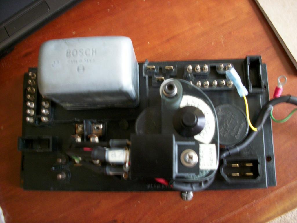
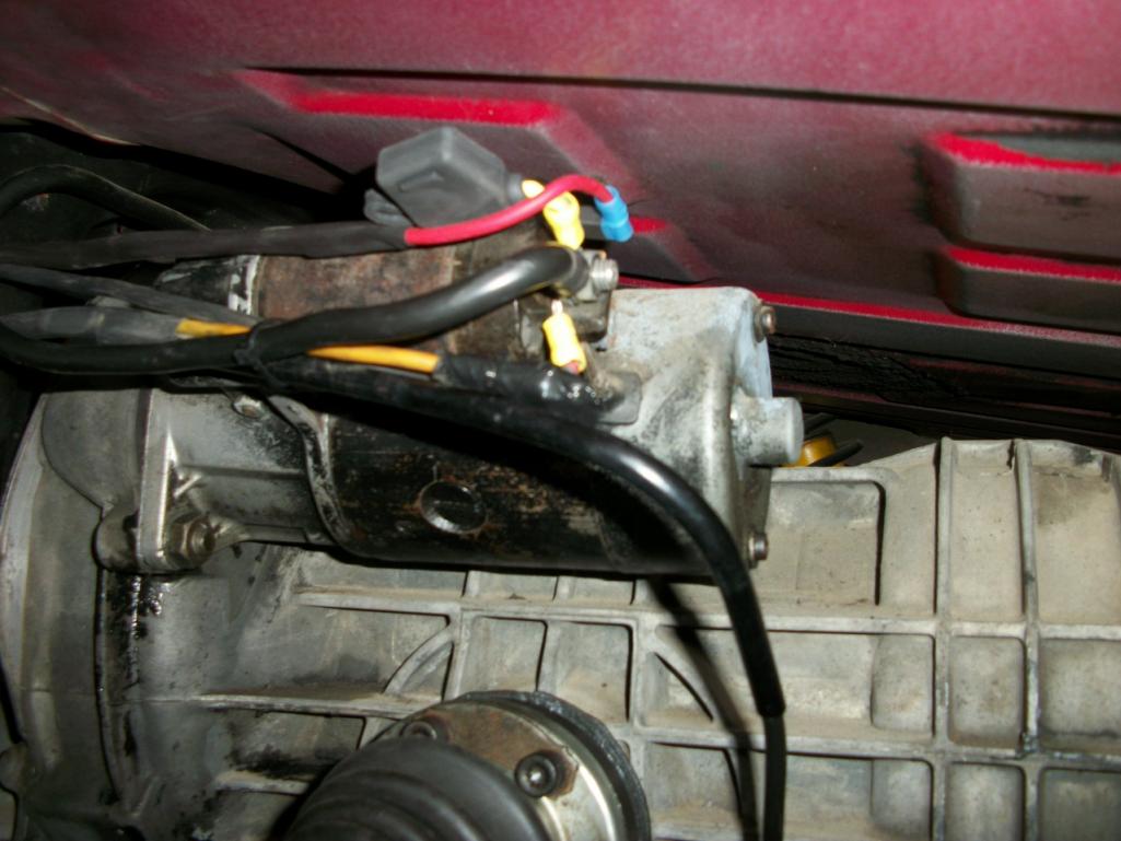
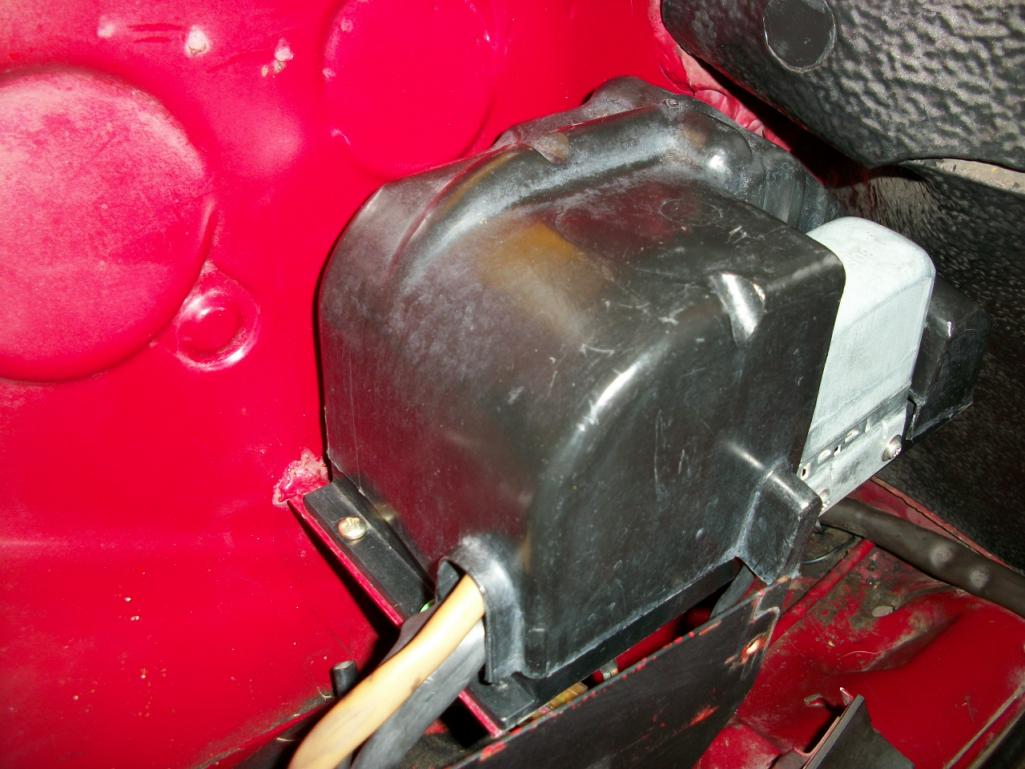
Installed the relay on a small bracket on one of the mounting screws for the relay board. Ran a new small yellow wire to pin 6 of the 12 pin connector and a brown ground wire to the bracket . Ran two 12 ga. wires fron the relay to the solenoid with the hot wire having an inline water resistant ATC fuse holder with a 30 amp fuse. Put some heat shrink around the normally used large yellow wire to protect it. On the solenoid side used tape to protect the connector that used to be hooked to the solenoid.
This relay uses 140 mili-amp so not a very large inductive spike to worry about, but I installed a supression diode across the relay coil anyway. Also put a larger one across the solenoid coil at the relay ( 87 to ground). This supresses the solenoid coil inductive spike to protect the relay contacts.
here are a few pics, and a link to more info: http://www.google.com/url?sa=t&rct=j&q=starter%20solenoid%20wiring&source=web&cd=12&ved=0CIoBEBYwCw&url=http%3A%2F%2Fwww.aeroelectric.com%2Farticles%2Fstrtctr.pdf&ei=UuIZT8i0KaGXiALkmfXQCA&usg=AFQjCNFm_afRQRZKsLHeg_6KDxZdKYQYGw This is the aeroelectric link
Oh, I tested it several times and it works just fine.
Tom
Edit: changed back EMF to inductive spike, sorry if this confused anyone. Inductive or transient spike is the correct term for what is happening here
Attached thumbnail(s)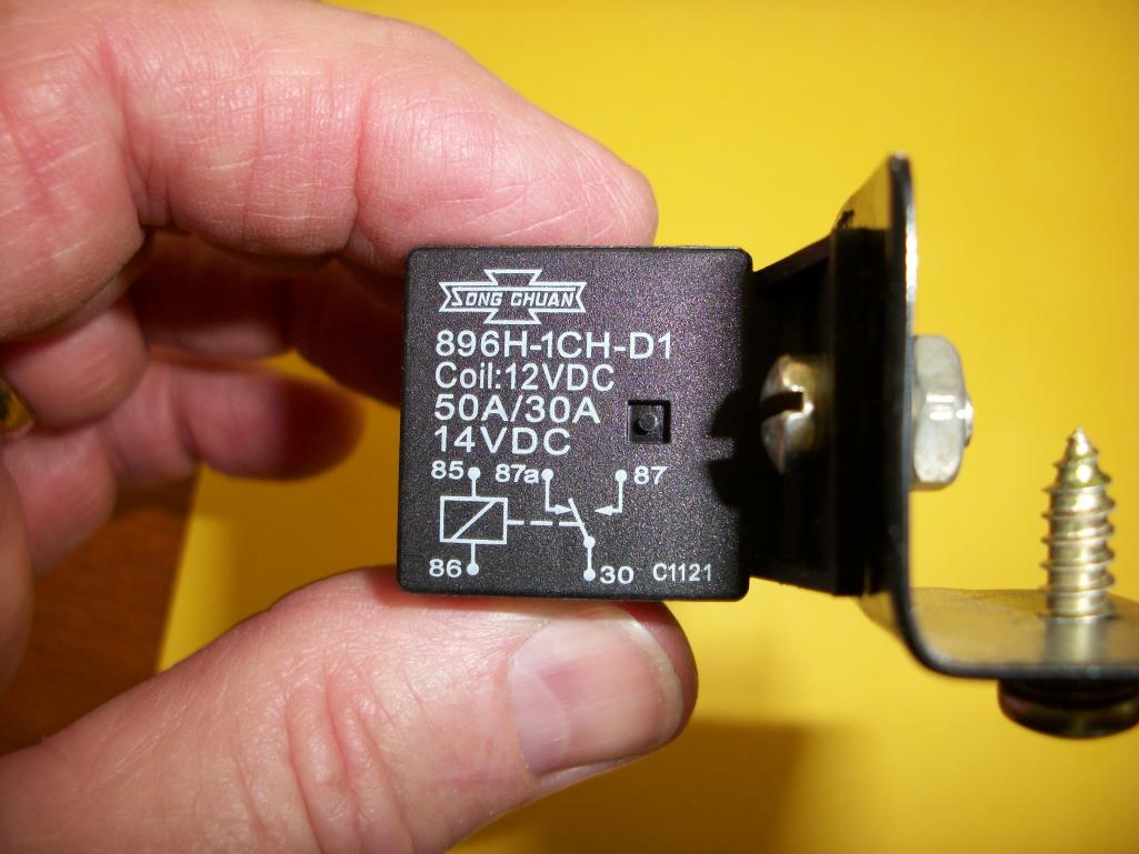
Posted by: Tom Oct 25 2011, 06:33 PM
Pics are large, so several posts will be needed.
Attached thumbnail(s)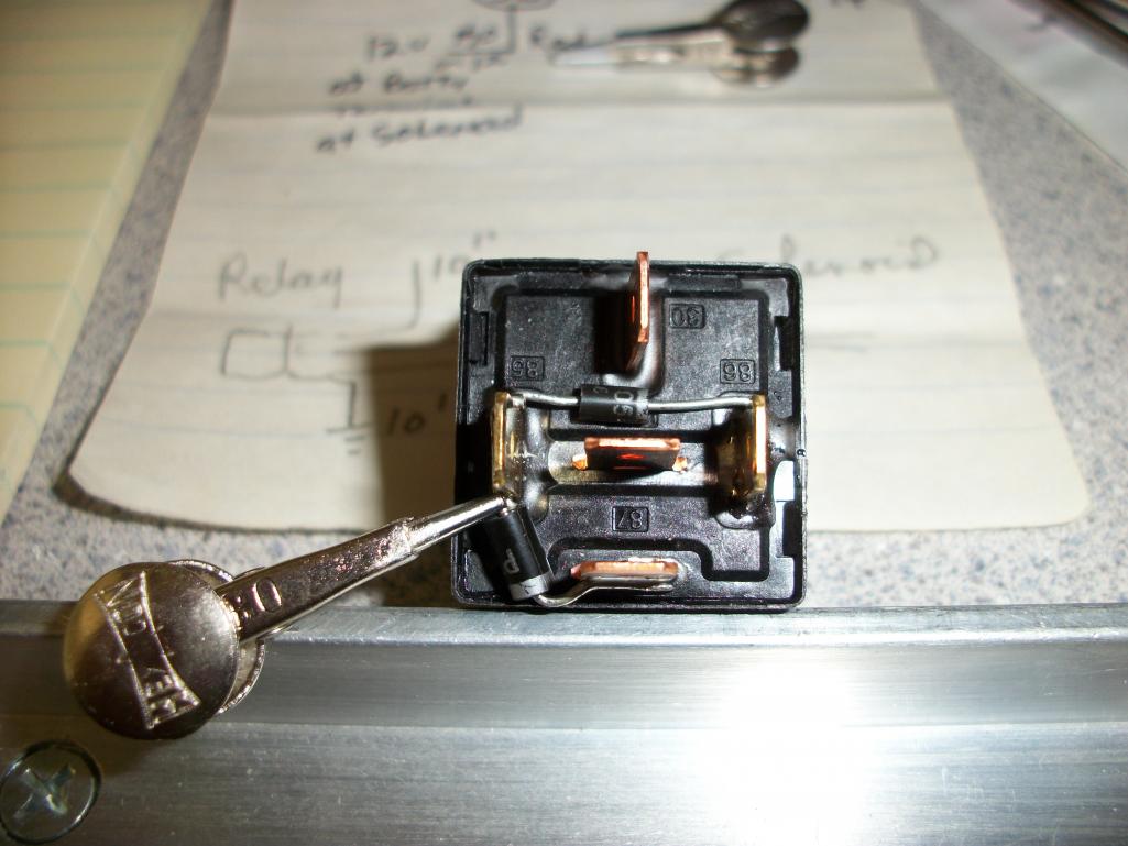
Posted by: Tom Oct 25 2011, 06:34 PM
another one
Attached thumbnail(s)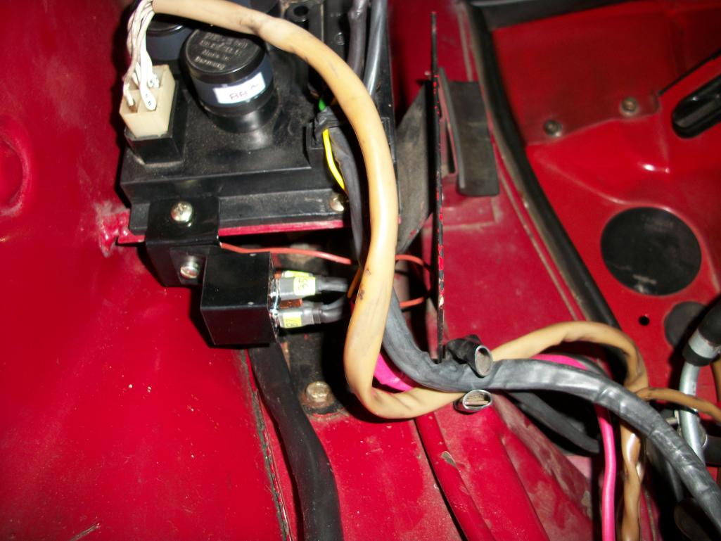
Posted by: 76-914 Oct 25 2011, 08:28 PM
Very nice Tom, but I'm not taking my Ford relay off. 
Posted by: Tom Oct 25 2011, 09:20 PM
76-914,
No reason to, the Ford relay is just great. I just wanted something hidden and different. Plus I had wire left over from the kits. My idle hands needed to do something!! LOL!
Thanks for the compliment too.
Tom
Posted by: Drums66 Oct 26 2011, 05:19 PM
.....Copy of the hot start kit in another location 
& I'll also give you a compliment...is fine,looks good!
(hope it turns out to be as reliable as mine was....about 10 yrs old)

Posted by: Tom Oct 27 2011, 01:41 PM
Drums,
Thanks for the compliment.  Yea, by now they are all copies.
I expect it will last OK, but the next time I order any parts, I will order myself a spare relay just in case. Diodes are cheap at Radio shack, about a buck and the relay was $3.08, already had the wire from the kits for the fuses left over, the inline fuse was $3.29. So all together I have about $10.00 in this mod. I never had the "hot start" problem with this car, just wanted to nip it in the bud so to speak.
I can't get the link to transfer but here is the info that really got me interested in doing this modification.
aeroelectric.com.
Very informative write up. Even mentions that lots of small foreign cars come with no starter relay and end up having key switch problems.
Tom
Posted by: Tom Feb 9 2012, 06:40 AM
I have been thinking of the next generation of this and want to add a push to start switch so when I need to "bump" the engine over it will be easy to do so from the engine compartment. A rubber cover over the push switch would keep accidental bumps to a minimum.
Tom
Posted by: Prospectfarms Feb 9 2012, 07:10 AM

I have been thinking of the next generation of this and want to add a push to start switch so when I need to "bump" the engine over it will be easy to do so from the engine compartment. A rubber cover over the push switch would keep accidental bumps to a minimum.
Tom
The "bump" feature could also be useful as a "get me home" solution when the plastic electric ignition switch fails -- as they are so prone.
One ? I thought the starter juice was already relayed to the bendix. Incorrect? (AC VW's are not, and the kind of relay you've described is a good modification, but I thought that with all those five prong relay's, at least one would be switching starter current.)
Nice photos for your project. Thanks.
Posted by: vsg914 Feb 9 2012, 07:16 AM
So you spent a little time and money to fix a problem that didn't exist? You have way too much free time.
Posted by: Prospectfarms Feb 9 2012, 08:15 AM

http://www.914world.com/bbs2/index.php?showtopic=129140&hl=hot%20start%20relay&st=40
http://www.914world.com/bbs2/index.php?showtopic=94947&hl=
Posted by: pcar916 Feb 9 2012, 08:54 AM
... add a push to start switch so when I need to "bump" the engine over ...
I have my button on the relay board under the dash and fed directly from the battery. I've never had to use it to get around a bad ignition switch, but had to after a spin at Texas Motor Speedway at Parade in 2004 the switch wouldn't work... the button however, worked like a champ.
I don't really want people to be able to see it. Then they might push it and if the car is in gear, which it will be if the car is parked, it's gonna lead to an embarrassing moment, possible an expensive one,
Posted by: Cap'n Krusty Feb 9 2012, 09:15 AM
Look out Maude, here comes the rain on the parade!
In your search for a "hidden and different" location for your hot start relay, you've put it outside the protective cover for the relay board, exposed the connections to moisture by mounting the relay on its side, mounted it where it takes a long run of heavy wire to be effective, and used cheap Chinese crap for a relay.
In theory, you want a relay that will trigger at the low voltage often supplied buy the aging wiring on a 914, and you want it as close to the starter as possible, while keeping the connections out of the elements as much as possible. That's why I use a 6-volt Ford type relay, mounted close to the starter, and cover all splices and connections, other than those directly on the relay posts, with heat-shrink tubing. A fuse is unnecessary, and just another potential failure point. BTW, I have customer cars that have seen daily use for more than 25 years with the 6V relays, without a single relay failure. Ugly? Sure, but they're under the car where no one sees them, and they're convenient for service or bypass should they ever fail, which they don't.
The Cap'n
Posted by: 76-914 Feb 9 2012, 09:17 AM
I have been thinking of the next generation of this and want to add a push to start switch so when I need to "bump" the engine over it will be easy to do so from the engine compartment. A rubber cover over the push switch would keep accidental bumps to a minimum.
Tom
Tom, if you kit this up, I'll take one. 2 reasons. You know my Chinese Ford style relay fused after < 3 days; 2nd, the push button start function.

Posted by: Tom Feb 9 2012, 09:26 AM
pcar916,
I haven't finalized what I will do yet and was kicking around the idea of putting a solid cover that would have to be unscrewed to get to the push button. Your point is well taken and I think a solid cover would be best for safety's sake.
vsg914,
Obviously your cars have never had this problem. I am sure many others have had good luck with their cars also. This is my third 914 and my first one had the hot start problem often. Back then I just put a push to start switch back in the rear engine tin. I understand some don't like this idea and that's OK. However, it's hard to ignore the fact that this is a weakness on these cars. I have seen at least 8-10 threads on switch replacement in the last year. And you are right, I have way too much free time on my hands since I retired. 
Tom
Posted by: Tom Feb 9 2012, 09:29 AM
Cap'n Krusty,
Rain away, we PNWers are used to it!
Tom
Posted by: andys Feb 9 2012, 11:31 AM
My '47 Ford had a button right on the relay that would move the contact and allow you to run the starter. I don't think the later ones have that feature.....It looked exactly the same as the one we today call the old Ford starter relay. Either way, that relay (solenoid) was bullet proof.
Andy
Posted by: ClayPerrine Feb 9 2012, 12:28 PM
We had hot start problems with both 914s, but putting on a gear drive starter cured that once and for all.
Posted by: pcar916 Feb 9 2012, 12:58 PM
... putting on a gear drive starter cured that once and for all
 Never had another problem. I have four or five used 911 Porsche starters boxed up and just sittin' on a shelf. I can't think of any reason to take the time to fix 'em.
Posted by: Tom Feb 9 2012, 02:10 PM
Prospectfarms,
No starter relay in the 914. There is where the problem starts. The inductive spike from the collapsing field causes premature wear and damage to the key switch and eventually causes failure of starting when the engine is hot. I suspect this can be all boiled down to the carbon deposits building up in the key switch causing more and more voltage drop across that contact until eventually the voltage drop is enough that the solenoid will not operate via the key switch. During bench testing myself, I have found that 9 volts or more is needed to operate the solenoid, any less due to bad contacts/wiring and the solenoid does not operate. Replacing the key switch/cleaning contacts should fix that. I haven't had to replace my key switch yet, but reading threads where others have, it seems like a semi-hard job. To me, a small relay to replace that would take 10 minutes and cost 5 bucks seems like a better solution.
Much of what I am repeating is in the article in the link in the first post if anyone cares to read it. Or you could go to the IEEE webswite and research relay contacts and why they use special alloys to reduce the arc damage on the contacts. key switch contacts are just copper I believe, or copper coated.
I am just putting info out here for those who want to use it and I would hope that those who do will confirm this by researching the links for theirselves.
I have no plans at this time to make kits for this as there are already vendors that supply this type of modification, minus the "bump" feature.
Tom
Posted by: Prospectfarms Feb 10 2012, 12:15 AM
Yes, I understand that every time you open a circuit to a coil the juice wants to keep flowing ("collapsing field" ) There are discussions about that effect on all kinds of automotive and MC boards dealing with a variety of different circuits and the consensus seems to be that it is helpful to either: put a diode across the wires near the coil (in this case, the starter) and/or to relay the current, or both. They didn't have cheap semi-conductors in 1972 then and I guess they must of run out of room on the panel for one more relay.
Do you recall discussing how my ignition harness crisped when the AAR grounded itself? It was fused from the engine bay panel and managed to burn anyway. I've fused the (new) red wire ever since.
Posted by: Elliot Cannon Feb 10 2012, 10:53 AM
Look out Maude, here comes the rain on the parade!
In your search for a "hidden and different" location for your hot start relay, you've put it outside the protective cover for the relay board, exposed the connections to moisture by mounting the relay on its side, mounted it where it takes a long run of heavy wire to be effective, and used cheap Chinese crap for a relay.
In theory, you want a relay that will trigger at the low voltage often supplied buy the aging wiring on a 914, and you want it as close to the starter as possible, while keeping the connections out of the elements as much as possible. That's why I use a 6-volt Ford type relay, mounted close to the starter, and cover all splices and connections, other than those directly on the relay posts, with heat-shrink tubing. A fuse is unnecessary, and just another potential failure point. BTW, I have customer cars that have seen daily use for more than 25 years with the 6V relays, without a single relay failure. Ugly? Sure, but they're under the car where no one sees them, and they're convenient for service or bypass should they ever fail, which they don't.
The Cap'n
Oh man! Don't you just hate it when you have to agree with that Cap'n Krusty guy? Do you suppose after 75 years of working on these cars he knows what he is talking about.


Posted by: 76-914 Feb 10 2012, 07:24 PM
Prospectfarms,
I have no plans at this time to make kits for this as there are already vendors that supply this type of modification, minus the "bump" feature.
Tom
Too late, I already ordered one.

Posted by: Tom Apr 6 2012, 10:49 AM
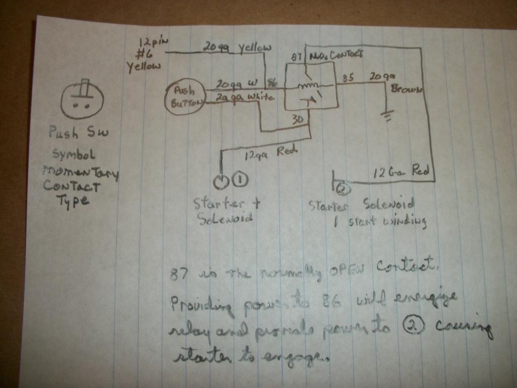
Well, now that I have the fuse block kits all done, I had time to get back to my project. Have the relay and push button mounted, now have to draw a wiring diagram and get the wires installed. It fits under the cover just fine!
Tom
EDIT: the wiring diagram is done.
Attached thumbnail(s)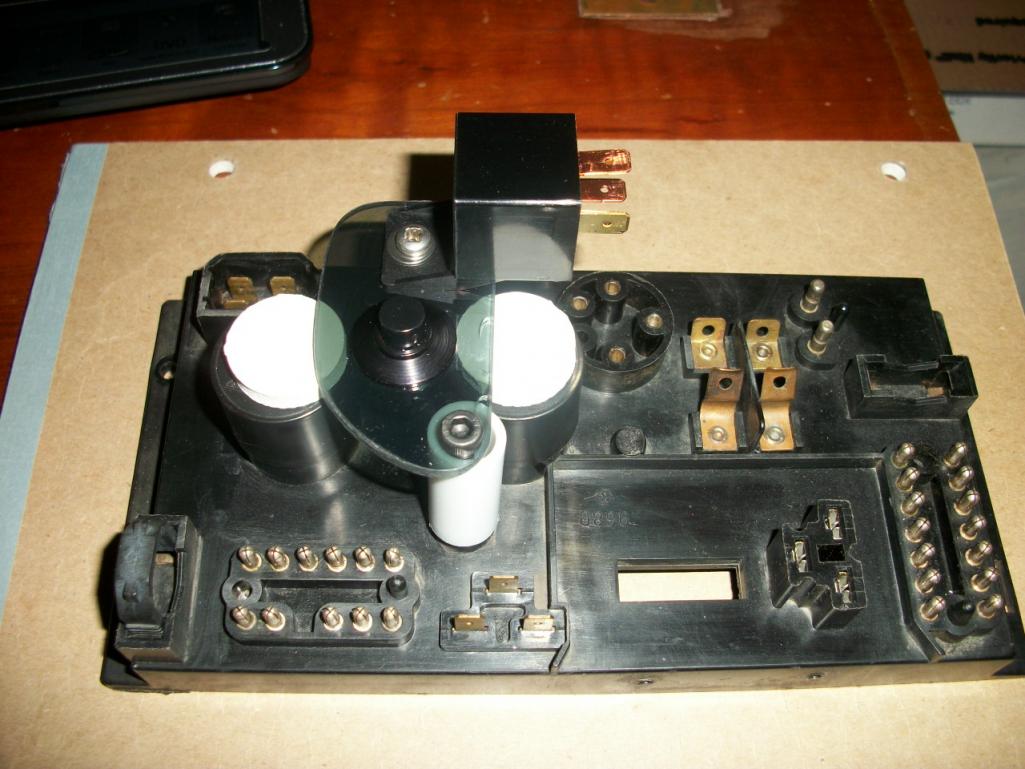
Posted by: Tom May 15 2012, 06:01 AM
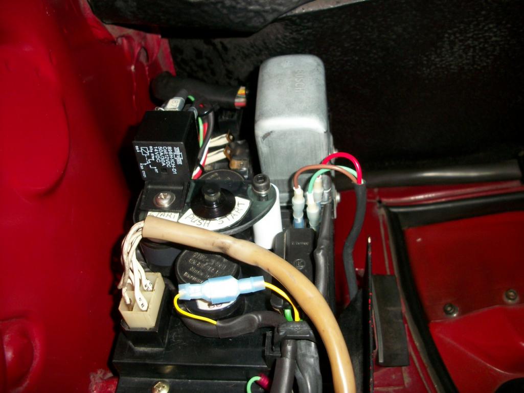
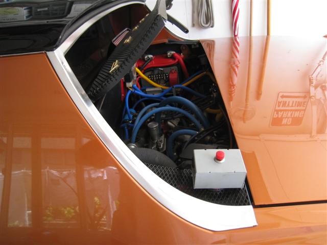
With no forum to spend time on, I found time to finish up my generation 2 starter relay with bump feature and got it installed. It works great. Key off and just push the start switch on the relay panel for a bump. Pics show installation on the relay board, then installed on car, and finally stealth mode. With cover on, it is not noticable that there have been any changes made except for the extra wiring harness! Don't know how many would even notice that unless they were looking for it.
Tom
Attached thumbnail(s)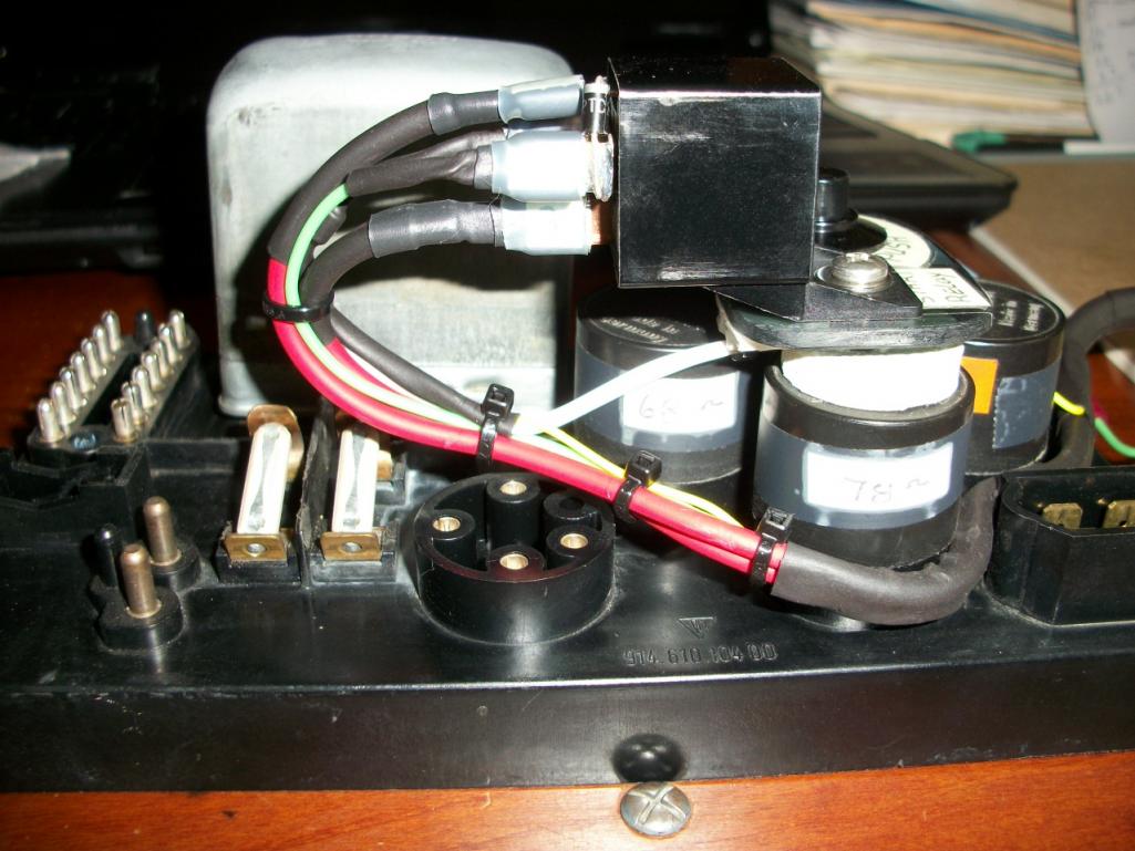
Posted by: 76-914 May 15 2012, 09:15 AM
Tom, I received my kit while this site was down. Can't wait to get it installed but my wife drafted my services whilst the board was down. I suspect my next kitchen pass won't be for another couple of weeks. I'll post up when I can. Very nice kit. 
Posted by: Tom May 15 2012, 01:11 PM
Kent,
I sent you a PM. I think I put in some instructions on how to get the heat shrink on the rear wires, but just in case you now have a way to get in touch. Glad you like the kits.
Tom
Posted by: Valy May 15 2012, 01:20 PM
Tom very nice but a word of advise:
Please, put a label next to the button asking to check that the transmission is in neutral.
I have a friend who was severely injured with something similar - he installed a remote controlled start button and got himself injured when the car jumped and squeezed him against the wall. Both his legs were fractured.
Please, please, please...
Posted by: jim_hoyland May 15 2012, 04:33 PM
Like your idea, very clean installation. If the wire to the coil is hot, will the engine start ?
Posted by: Tom May 15 2012, 07:08 PM
Jim,
With the key off, the coil has no power and if it is fuel injected, neither does the ECU, so no it should not start. All you are doing is the same as putting a screwdriver across the hot wire on the solenoid to the solenoid power connector, Ie. engaging the starter only. About the same as a remote start switch that mechanics use to turn the engine over without starting the engine, kind of like when setting the points or valves. Releasing the button will stop the "bump" feature. There are other ways to do this and the same safety measures need to be observed. This is a good way to "save" the electronic ignition mods from having to have the key switch on, which has a detremintal effect on the electronic ignitions.
Valy,
No one can engineer out all of the mistakes a home mechanic can do to himself, which is one of the reasons I am not doing kits for this mod. I only did one extra kit for someone I felt had the expertise and understanding to use it safely. But your reasoning is very good and understood. Besides that, the only thing that could happen if the car is in gear, is the car will move forward or backward. To push the button, you would need to be on the driver's side reaching into the engine bay and not in the path of the car.
To all, there is an addition I have made to the schematic to ensure there is no power feedback to any other circuits. It is adding a diode between the normal start circuit and the push switch. This ensures no power goes from the push switch to pin #6 of the 12 pin connector on the relay board. If anyone is interested in doing this to their car, let me know and I will post an updated schematic.
Thanks,
Tom
Posted by: jim_hoyland May 15 2012, 07:33 PM
Please post the schematic, the parts list, and instructions. I'd really like to do this. Just need some guidance.
Posted by: Tom May 15 2012, 09:22 PM
Jim,
I'll put an updated schematic tomorrow and some instructions as to how to do this. Also I will include the part numbers for the relays and diodes. As for the push to close switches, I can only give you the electrical characteristics as the two switches I used are ones I had left over for some projects many years ago. But they are basically just a momentary close push to close switch. Doesn't need to be very heavy duty as the relay only draws about 150 mili-amps. Any push to close momentary contact switch that will handle 1 amp will be sufficient.This saves the high current from going through the key switch. Normally, the starter solenoid draws about 35 amps initially for as long as the solenoid needs to close and then the large electrical contacts in the solenoid carries the majority of the solenoid current and the current through the key switch drops to about 10 amps. With this modification or similar starter relay set ups the current through the key switch is greatly reduced. BIG difference between 10 amps and 150 mili-amps in the resulting arc across the key switch contacts.
Tom
Posted by: Tom May 16 2012, 06:15 AM
As you can see from the pictures the large yellow wire needs to be removed from the 12 pin connector and insulated at that end as well as the starter end. A new 20 ga. yellow wire needs to be soldered to the pin for #6 of the 12 pin connector. The other end will need to be soldered to the anode of D1. The cathode end of D1 and a 20 ga. white wire need to be crimped/soldered or both depending on the type of female spade connector being used and this connector labeled 86. The other end of this white wire will go to either side of the push switch.
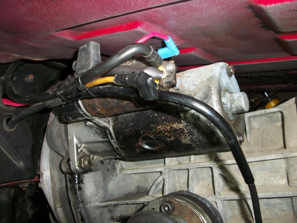
The other white wire from the [push switch will need to go into another female spade connector along with one of the large 12 ga. red wires and be labeled 30. This red wire will need to be about 5 to 5 and 1/2 feet long as it and the other large red wire goes back to the starter area. The starter end of this wire is where you need to place the inline fuse holder and on the end of the fuse holder wire you will need a ring terminal to place on the starter terminal with the battery lead. The other red wire needs a female spade connector and should be labeled 87. The other end of this wire(87) will also need a female spade connector to allow connecting to the solenoid male spade connector. The last wire is a 20 ga brown that needs to be long enough to place a ring terminal under one of the securing screws on the relay board ( ground).
The diodes are there to D1- steer the push button voltage to only the relay and not back to the #6 pin of the 12 pin connector, and D2 - to suppress the inductive spike and give the relay contacts a longer life.
Some parts were ordered from DELCITY and some Radio Shack or local parts houses. I carry an extra relay just in case it goes out as it may be hard to find one at inopportune times.
As can be seen in the pics, I don't have a rear window defog relay. If I did, I would have had to route the wires a little differently. Also check your relay board for the metal insert to screw the hold down bolt into. Later one don't always have it. Mine did not and I made one from brass and glued it in.
Before you attempt this, please have someone you trust with electrics look over the schematic and give a second opinion for you.
Tom
Attached thumbnail(s)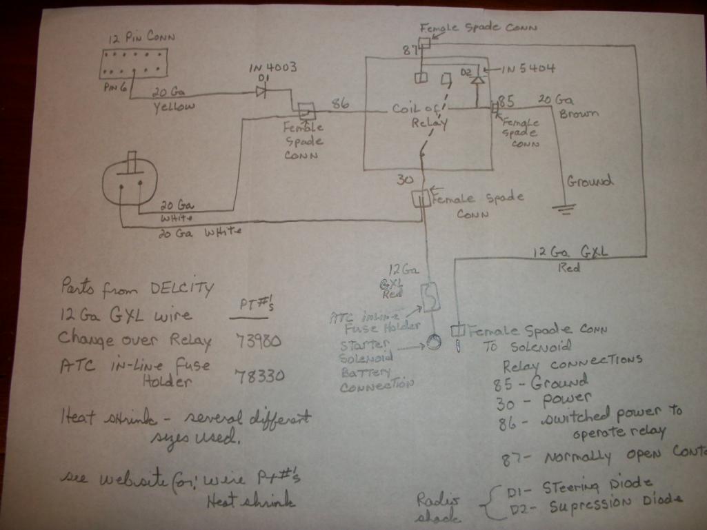
Posted by: Tom May 16 2012, 06:18 AM
Additional pics for illustration purposes.
Tom
Attached thumbnail(s)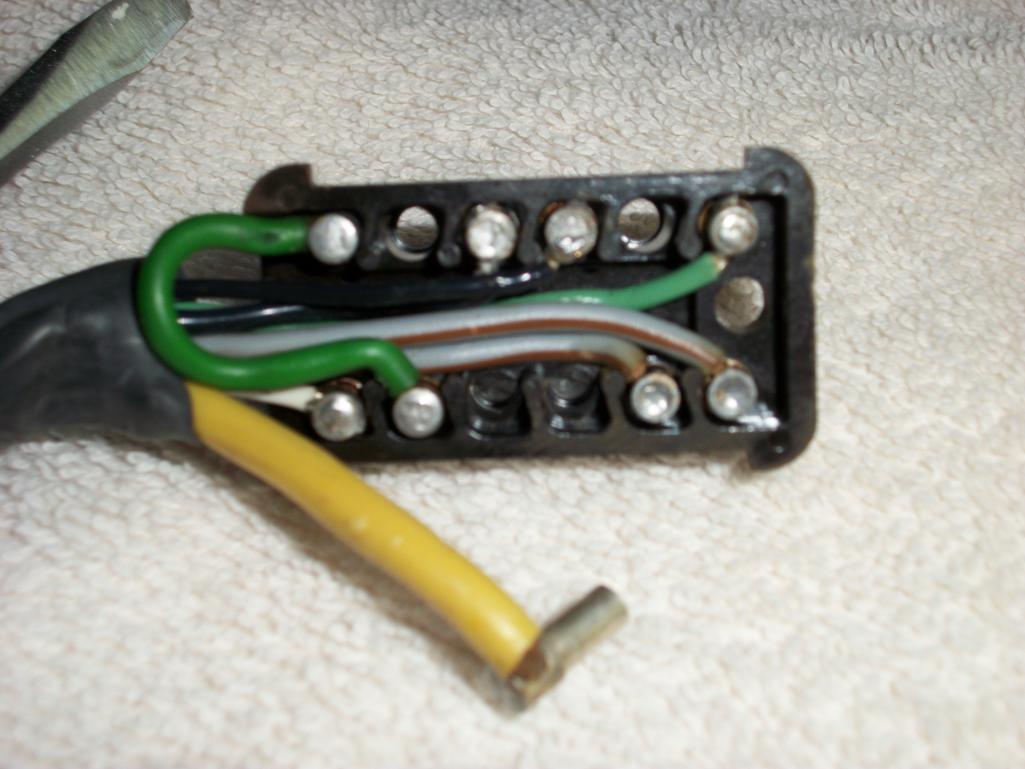
Posted by: Tom May 16 2012, 06:20 AM
more.
Even though this is first gen of this mod, you can see the pin 6 now has a smaller yellow wire and the large yellow wire has been insulated.
I think that should be enough to show anyone who would think of doing this mod what amount of work is envolved. Make sure you get the relay board end completed first, run the heat shrink over the two red wires leaving plenty of room for the starter end's work to be done. Shrink the first piece of heat shrink, then after cooling put another piece up over the first one that can be slid back and shrunk after the starter end's work is completed.
Tom
Attached thumbnail(s)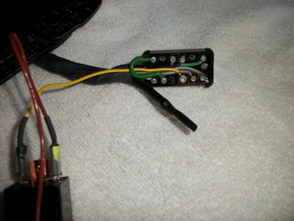
Posted by: jim_hoyland May 16 2012, 08:49 AM
Am I correct that the relay will be used by both the regular key start and the momentary switch ?
Also, I have a 1.8 L-Jet where the power relay, FP relay, and 4-plug connector are not used ( except for the yellow jumper wire ) I'm thinking of using that unused portion of the relay board for the relay. Hmmmm..........
Posted by: Tom May 16 2012, 08:58 AM
Jim,
Yes, the relay works for both the key switch start circuit and the bump circuit. Looking at the schematic, there are two times the relay is energized causing the starter to operate, 1- when the key switch is turned to start -yellow wire, and 2- when the push button is pushed- white wire.
As to using the portion of the relay board you speak of, I don't have any L-jet experience. Doesn't the start circuit still run through the relay board the same as D-jet?
Tom
Posted by: jim_hoyland Jul 3 2012, 06:21 PM
Just installed the relay today. How much amperage should the momentary switch be rated ?
Posted by: 76-914 Jul 3 2012, 06:32 PM
Jim, the amp load to activate the relay is minimal. I would think it is very low. Love mine.
Posted by: Tom Jul 4 2012, 03:12 AM
Jim,
The relay I used draws about 145 miliAmps, so a one amp switch is more than adequate.
76-914,
Glad to hear all turned out well on your installation.
Tom
Posted by: Harpo Jul 4 2012, 10:53 AM
Good afternoon Tom,
You posted that these kits are already available (minus the "bump"), who would that be?
Thanks
David
Posted by: Tom Jul 4 2012, 11:44 AM
Auto Atlanta sells them. They are in the catalogue for $25.80. They use a Bosch relay very similar to the one I used, just made up to be installed near the starter. Look for "hot start relay". Page 128. My catalogue is several years old, so price may be up.
Tom
Posted by: jim_hoyland Jul 6 2012, 02:35 PM
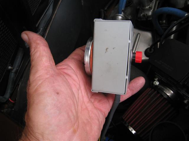
Finally completed the hot start relay and added the remote start switch. Mounted the relay under the trunk floor near the starter/solonoid so the wire runs would be very short. Then I mounted the momentary switch in a small metal box with a speaker magnet attached to the opposite side of the switch. The remote switch can be attached to the interior side panel out of sight or , when needed, stick to the grill.
Big thanks to Tom for illustrating the wiring and parts needed. So far, so good. Here's a few pics of the set up....
Attached image(s)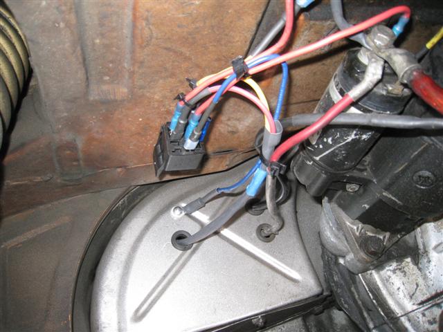
Posted by: jim_hoyland Jul 6 2012, 02:37 PM
Remote starter unit. Momentary switch and magnet...
Attached image(s)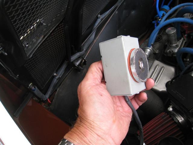
Posted by: jim_hoyland Jul 6 2012, 02:38 PM
Installed out of view, and set up on grill....
Attached image(s)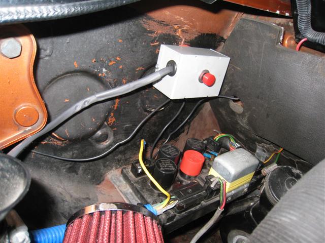
Posted by: Tom Jul 6 2012, 07:02 PM
Jim,
That is looking nice, glad it all worked out for you.
Tom
Powered by Invision Power Board (http://www.invisionboard.com)
© Invision Power Services (http://www.invisionpower.com)