Printable Version of Topic
Click here to view this topic in its original format
914World.com _ 914World Garage _ Frame rails...
Posted by: Jeroen Aug 15 2004, 02:55 PM
Didn't get to work on the 914 as much as I hoped over my vacation, but still made some good progress over the last couple of days...
Frame rails in the engine comp. are stripped naked
They still need some minor detailing here and there and the "hell holes" still need to be cleaned, but most of the hard work is done
Tonight I welded the rear shock towers to the frame rails
Quite a gap to fill...
Attached image(s)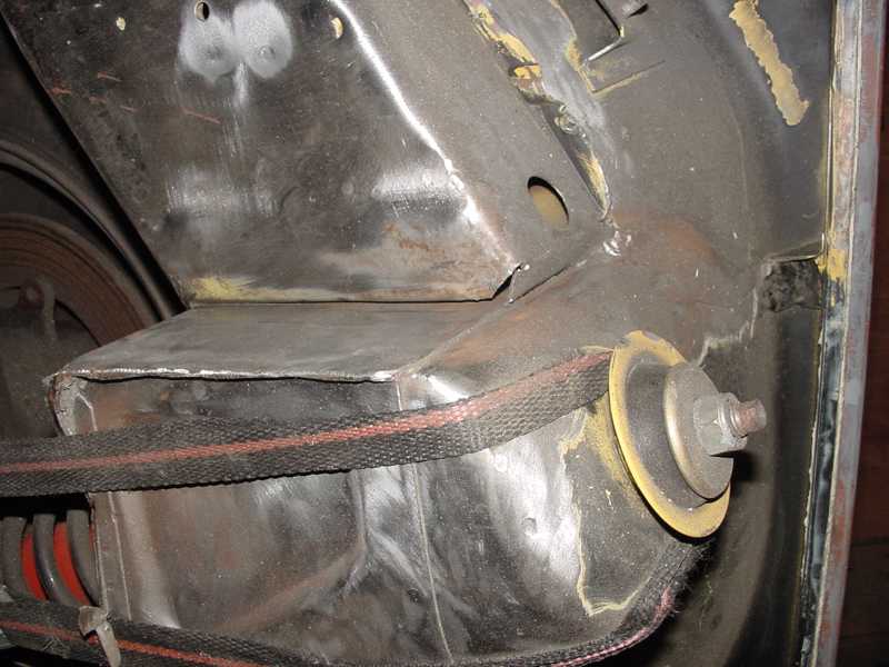
Posted by: Jeroen Aug 15 2004, 02:56 PM
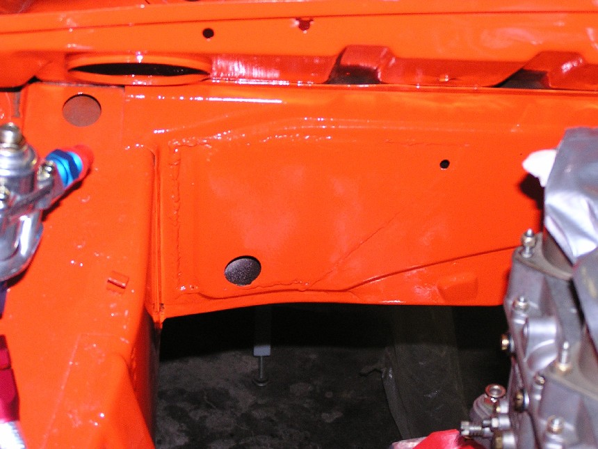
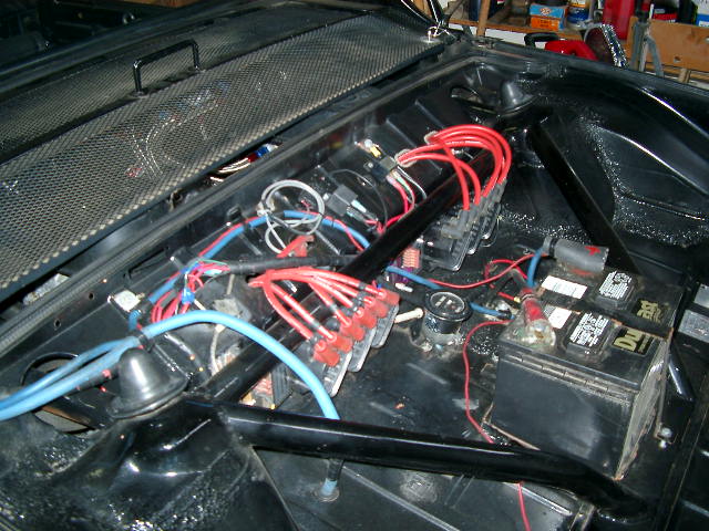
Welded up...

Attached image(s)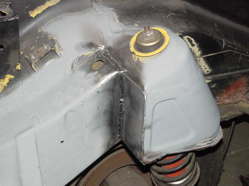
Posted by: Jeroen Aug 15 2004, 02:58 PM
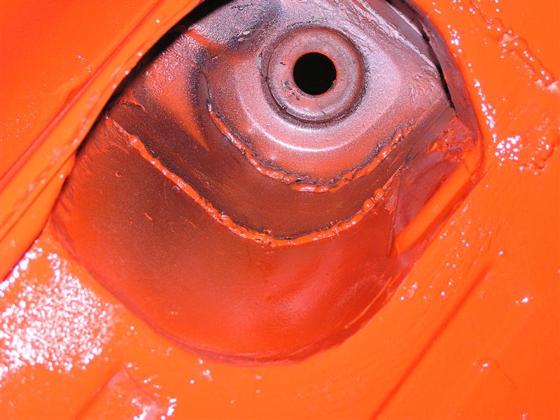
Top of the drivers side still needs to be welded, will do that later this week
Oh, the rust brown is just grinding dust. It's only visible in the pics 
Attached image(s)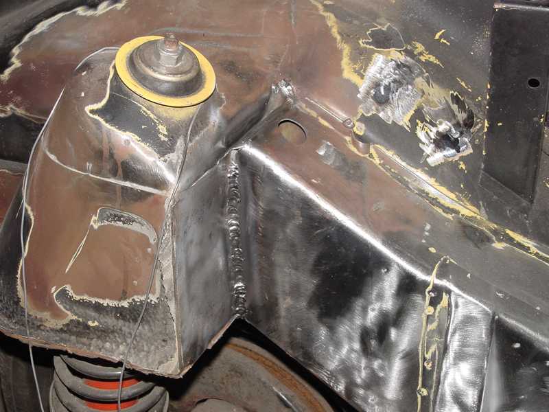
Posted by: Jeroen Aug 15 2004, 03:00 PM
Last pic for now...
I wanted to buy a better welding machine, but we also needed a new couch for the living room 
Attached image(s)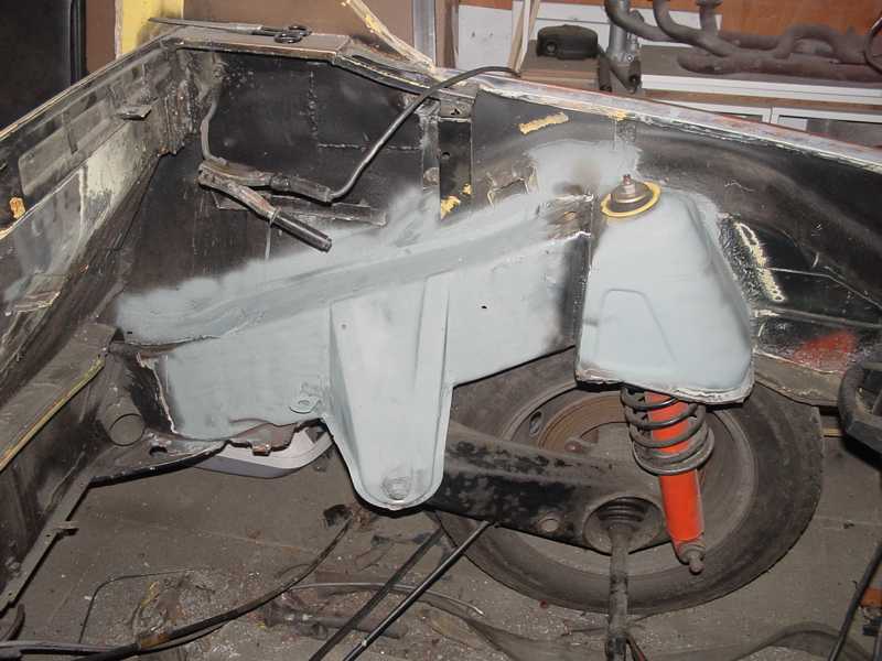
Posted by: watsonrx13 Aug 15 2004, 06:01 PM
Damn, the trunk is GONE and the engine shelf...
Looking good.... 
Posted by: seanery Aug 15 2004, 06:15 PM
Gotta have room for that 917 motor! 
Posted by: Gint Aug 15 2004, 08:13 PM
Good lookin work Jeroen.
Posted by: Brad Roberts Aug 15 2004, 11:56 PM
Good job Charlie Brown 
Perfect pic to show people WHY our cars split the outer frame rail in the inner fender. I have a hard time explaining to people that the frame rails end in front of the shock tower. This will make life much easier. Thanks for the pics.
B
Posted by: Lou W Aug 16 2004, 12:04 AM
Wow, I never realized how those towers are attached to the frame rails. Thank you for the pictures. Brad, Now i know what you were talking about in one of the previous threads. You were explaining about the weak area's and how some of the frame stiffening kits don't really address the problems. Good stuff 
Posted by: Brad Roberts Aug 16 2004, 12:14 AM
You got it.
The GT stiff kit pieces that go inside the fenderwell are worthless. They weld onto a cover for the frame rail. Cut the cover off and install the stiff kit... then it would actually do something. You have to tie the frame rail to the shock tower better than the factory did. These pics show how the frame rail is only attached on front side of the shock tower. Over time the shock tower tries to rip away from the frame rail (Jeroen listened and welded it all up)
B
Posted by: jgiroux67 Aug 16 2004, 12:24 AM
Is there a way to do this without cutting out part of the trunk? Also, do you have to take the engine out to do this?
Posted by: brant Aug 16 2004, 08:36 AM
Damn.. nice job Jeroen.
I plagerized some of your ideas from the past and recently just got my car back from paint with the same seam welding...
I cut our access hole with a plasma torch to this same seam... welded it, and then welded in a bracket that tied the two parts together. I was able to put the cover back on and weld it closed again... ground down the welds and had the paint shot, so that you can barely even tell that cavity was opened up...
wish I had a digital camera (again)
brant
Posted by: Joe Ricard Aug 16 2004, 11:13 AM
Damn day lae and a dollar short. Wish I would have seen this before I did all my welding of the hell hole.
You know while you are in there stuff.
Posted by: rdauenhauer Aug 16 2004, 11:36 AM
I confused 
w/o seeing the original back eng. wall in place Im not understanding.
Are you saying the seam shown as unwelded in the first pic (rail to tower ) is how the factory left it? No spots nuthin?
Posted by: Brad Roberts Aug 16 2004, 11:43 AM
It has small tabs that are folded over and spot welded to the front of the shock tower.
B
Posted by: Jeroen Aug 16 2004, 05:07 PM
Maybe this pic helps you get a better idea...
Here you can also clearly see that the firewall is actually double walled
(hence, no need for one of those rear shock braces that you see sometimes)
Attached image(s)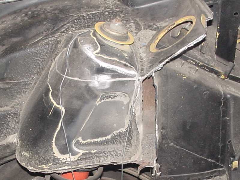
Posted by: Eric_Shea Nov 16 2004, 04:44 PM
I'm going to revive this thread from August.
I looked at a bare tub today and it looks as though the longitudinal is spot welded to the shock tower along that seam that is clearly visable in Jeroen's 1st picture. It looks as though it is spot welded from the inside. I was able to look up into the shock tower and see spot welds where the longitudinal would terminate.
Question 1:
Is this correct? Has anyone seen inside the longitudinal at this point? Brad? Brandt? Jeroen?
Question 2:
That being the case, are you seam welding this area for strength?
Question 3:
That not being the case, did the factory forget to weld the longitudinal to the shock tower in this area?
Question 4:
Brandt, any further info on your procedure?
Thanks in advance!
E.
Posted by: brant Nov 16 2004, 05:24 PM
Eric,
1) Actually I have not looked inside a longitudinal at this point... I've looked at it from the outside (both the inboard and out board outsides)
2) Yep.. that was my intent. Seam welding for strength.
The tube frame cars all run the roll cage to the top of the shock tower for the same reason. The top of the shock tower wants to pull up from the longitudinal and shears the factory spot welds...
3) I think the factory spot welded it a little bit, but with the BIG high rate springs the race cars use these days the factorys welds are not adequate.
4) I just seam welded the inside (from within the spring tower cavity) and then opened up the cavity on the engine side and seam welded the outside from there....
I'm not allowed to run my roll cage to the suspension points.. thus the reason I tried it this way.
Also, I think my one picture on my thread that shows the seam welding inside the tower... That picture only shows one half of the inside, and I went all the way around on the inside (but didn't get a good picture of it...)
brant
Posted by: Gint Nov 16 2004, 05:27 PM
 Please? This is for my tub.
Hey Eric,
Brant posted this in his thread:
this one is for you.
I mentioned this previously, but I used a plasma cutter to open the frame cavity and do some welding inside to brace the rear towers..... Then closed it back up.
You can see my welding seam.. Its kinda a big triangle (about 6inches long):
Here is the other picture Brant referred to of the inside of the shock tower.
Here is the seam welding on the rear towers inside..
Jeroen, I mentioned this once a while back... I don't have to tell you not to over look this area. 1/2 of the rear seams are inside. You can't see them due to all the body filler the factory puts in there. you can grind that crud out with a wire wheel and then get to them.
I don't have a pic of it, but I also cut open to access the frame end in the engine bay. Right where it butts up to this tower. We welded that and then closed the access portal back up.. Welded it closed and you can barely tell after a bit of grinding
here she is from beneath:
Posted by: Gint Nov 16 2004, 05:30 PM
Thanks Brant!
Don't stop there.
Jeroen, interested in hearing your perspective on this as well. In fact anyone who has been in this area, please let us know your thoughts about strengthening it.
Posted by: brant Nov 16 2004, 06:01 PM
Mike,
one more thing and then I'll shut up and let Jeroen and others reply....
I don't think that you have too worry tooo much about this area on a street car.
Brad always used to say it was only problematic on cars with around 300# springs...
I talked to AJ, and he kinda reinforced Brads statements.
AJ said that on the HUGE tube frame cars (with Downforce) they have to run Big springs (due to the downforce) and so they go ahead and reinforce those cars....
What I'm trying to say is that on a street car its not a common failure.
brant
Posted by: Gint Nov 16 2004, 06:09 PM
I hear ya, but if I want to do it, now is the time.
I don't baby my cars.
This car will see the track, even if it isn't much for the first few years.
It will get Mueller bearings which may necessitate stiffer springs.
It may also get much more motor and some point in the future.
And it could very well see significant track time after the shine of the resto wears a bit.
Posted by: Eric_Shea Nov 16 2004, 06:14 PM
Me agrees with Brandt.
Here's what we (Mike and I) discussed over the phone:
I thouhgt the longitudinal was spot welded there. A visual inspection of the tub kinda bears that out. As a "while we're in there" philosophy for a street 914-6 that might get driven hard, I thought that seam welding all the factory GT points like what Brandt has done (both inside and out of the shock tower) would be good. I also thought that one who knows how to weld very well could lay a bead down that line inside the rear shock tower where the longitudinal meets. With proper penetration of the weld it would make it stronger. You can see the spot weld so you can follow the joint, effectively seam welding from the backside.
Either that or not worry about that seam and seam weld all those other areas previously discussed.
Thoughts?
Posted by: brant Nov 16 2004, 06:23 PM
I know I said that I'd shut up, but oh well.....
my thoughts:
-probably not totally necessary
-better bearings should acually reduce the effective spring rate...
but if it was mine, I'd do a little bit of it since your there and it hasn't been painted yet.
brant
Posted by: Jeroen Nov 16 2004, 06:32 PM
Ok, I'll try and explain best as I can...
In the pic below, the sheetmetal plate marked "A" is basically the outside of the engine bay/reartrunk firewall. With outside, I mean the part that you look at when viewing from the rear trunk.
This piece runs from inner fenderwell to inner fenderwell.
At the seam marked "B" you can see how part "A" bends inward toward the rear window.
It sorta bends over the top of the long and is spotwelded there.
These spotwelds can be seen if you remove the seamsealer around the shock tower.
At the seam marked "C" the long has a small lip (aprox 1/4") that is folded to the inside of the long. This lip is spotwelded to part "A" from the outside (shocktower side).
They must have done that before the shocktower was welded in place.
So basically, part "A" is welded in between the shocktower and the long.
The seamweld I made on top, directly welds the long to the shocktower (because I grinded part A flush there)
Hope this makes sense... If not, shoot some more questions
Attached image(s)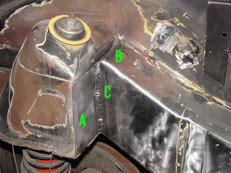
Posted by: Jeroen Nov 16 2004, 06:56 PM
If you wanna keep the firewall in place, like Brant. Doing what he did is a very good option.
In addition (I'm not sure if Brant did this) you can do some extra seamwelds on seam "B"
Seamweld part "A" to the long (from the engine bay) and seamweld part "A" to the top of the shocktower (from the rear trunk)
By doing so, you basically seamweld the top of the long to the top of the shocktower
Posted by: hargray2 Nov 16 2004, 07:11 PM
So you are referring to all of the area highlighted in yellow plus an area that can't be seen in the picture, which would be just below the letter D, right.
Attached image(s)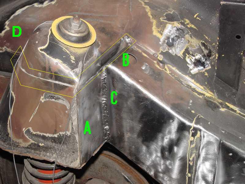
Posted by: URY914 Nov 16 2004, 07:16 PM
Jeroen,
Isn't the sheet metal on the shock tower a heavier (thicker) gage than other areas?
It seems like it when I tap on it (I know, not real scienific)
Paul
Posted by: URY914 Nov 16 2004, 07:20 PM
I'm going to cut my firewall out. and I'm going to cut the sheetmetal out that the tranny mounts to. I'm gonna run 1" tubing from the shock towers down to hold the rear od the tranny. 
Paul
Posted by: Gint Nov 16 2004, 09:28 PM
Thanks my friend. I think we have the info we need now.
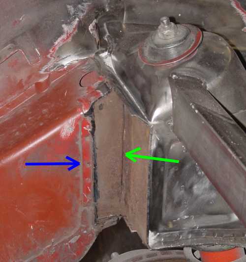
One more picture and commentary from another of Jeroen's threads. Just for completeness. This picture will help those like me who originally had trouble envisioning all of this without an actual 914 in the garage to look at. The cutaway of the firewall was especially helpful I thought.
I think this entire thread is a pretty good pictorial and description of the issue.
It's because the crappy connection from the framerails to the shock towers
Look at the picture below... the firewall has been cut out and shows the crappy connection from the framerails to the shock towers (green arrow)
The spotwelded seam from the firewall (blue arrow) is supposed to take care of all the stress... and like you noticed, it won't do a very good job at that...
Posted by: Jeroen Nov 17 2004, 10:30 AM
Not as far as I know. I believe that all the sheetmetal on the car is the same gauge
I have a cool pic of a disected (sp?) shocktower on my home computer.
It shows just how amazingly complex the 914 is
I'll post it when I get home.
Posted by: Jeroen Nov 17 2004, 10:47 AM
Daniel,
The weak spot is seam "B" and "C"
Some aditional welding round the shocktower wouldn't hurt of course...
Posted by: davep Nov 17 2004, 12:41 PM
I think a fully dissected set of views would be really helpful. Something to think about at the next sawzall party. Mark up all the pieces the factory used and kind of sequence the build process. Part B is spot welded to Part A along seam X. That would help us visualize the strengths and weaknesses of the construction. Then we can determine various fixes for street, track and race cars. Knowing where all the cavities are helps. I imagine the design engineers had a lot of fun trying to figure out how to build these cars.
Posted by: Jeroen Nov 17 2004, 01:11 PM
Here's the disected shocktower pic
This is just on example of how complex the bodystructure of the 914 is
It's just a briliant piece of design, even to today's standards
Then imagine the figured this out in the late sixties. No fancy CAD computers, nothing but a piece of paper and a pencil
When you're at a resto shop, you should take a look at some other cars of similar vintage. They're a joke compared to the ingenuity of the 914
I should have some more pics like this, I'll do a search...
(I can't take credit for this pic)
Attached image(s)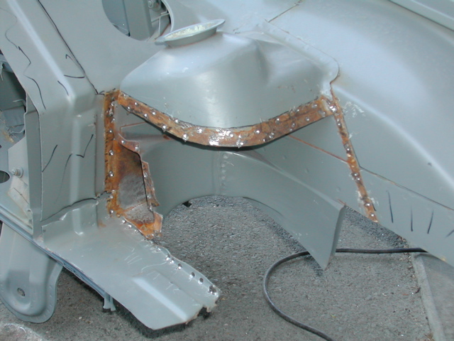
Posted by: URY914 Nov 17 2004, 01:14 PM
That is a great shot.
Posted by: Jeroen Nov 17 2004, 01:23 PM
Some sawzall pics, courtesy of Mike Mueller
Driver side shocktower
Attached image(s)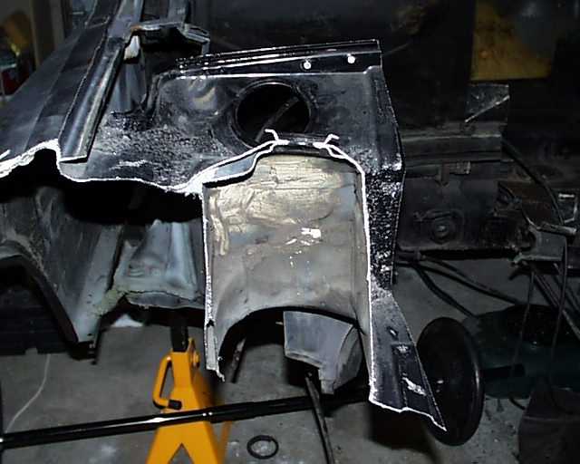
Posted by: Jeroen Nov 17 2004, 01:23 PM
drivers side front shoch tower
Attached image(s)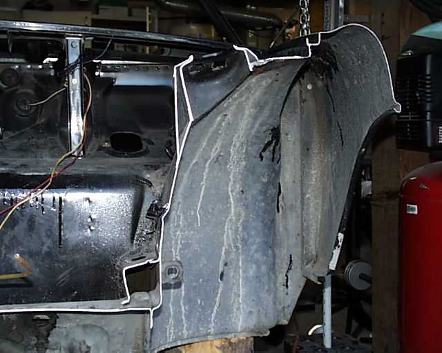
Posted by: Jeroen Nov 17 2004, 01:24 PM
drivers side front shock tower - close up
Attached image(s)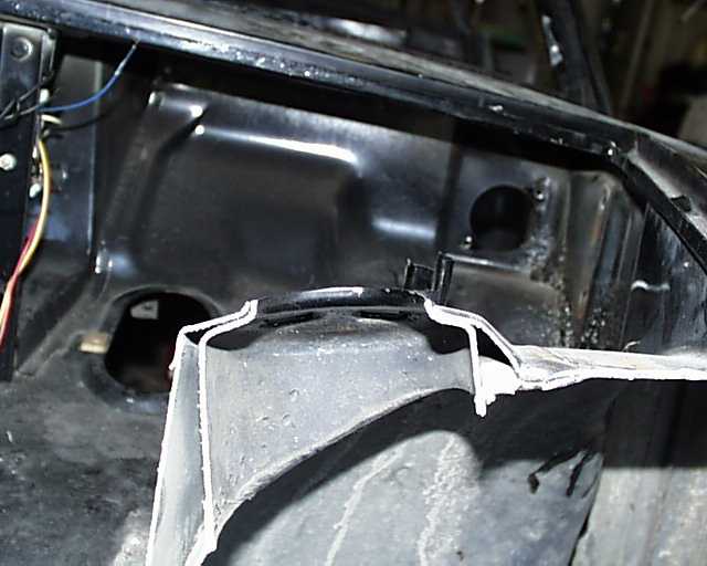
Posted by: Jeroen Nov 17 2004, 01:24 PM
firewall (passenger/engine)
Attached image(s)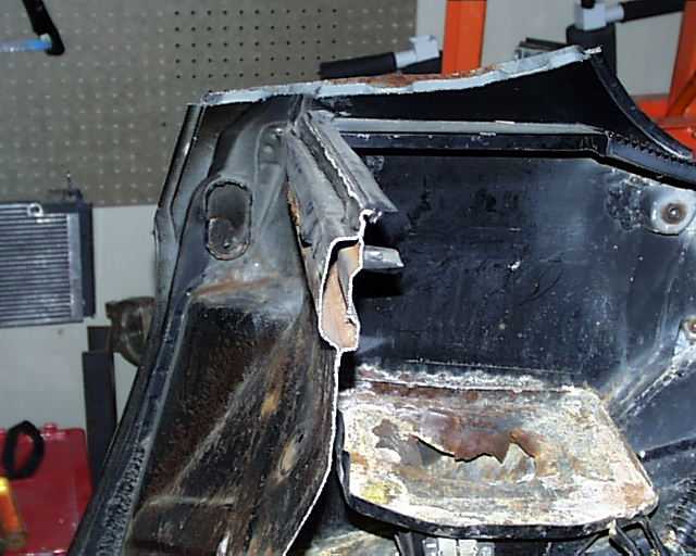
Posted by: Jeroen Nov 17 2004, 01:24 PM
rear trunk, x-section of the dogbone, near the tranny mount
Attached image(s)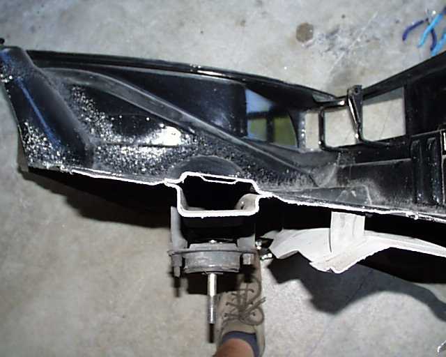
Posted by: Jeroen Nov 17 2004, 01:25 PM
last one...
Targa/roll bar inner reinforcement
Attached image(s)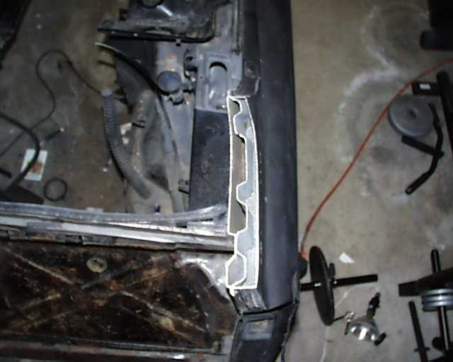
Posted by: Eric_Shea Nov 17 2004, 02:32 PM
OK... That's the answer I was looking for. It is welded, just not very well. Thanks.
I've looked at Gint's tub again this morning. Here's some things I'll throw out there as was my discussion with Gint a few hours ago:
1. Brad is right. (first time for everything
 ). The factory stiffening kit gets welded to a cover plate not to the actual longitudinal and shock tower area. This is an area of sheet metal that is pressed into the inner fender well and it sticks up about 1/8" to 1/4" depending upon the area. Those who have been there know what I'm talking about.
After looking at that area, I believe there is a fix for this that will make the factory kit "VERY" useful. That fix is this:
Tack weld the ends of the factory piece or use clamps to hold it in place (this is the long piece that ties the longitudinal into the shock tower). It is drilled rosette. With the appropriate drill, drill out all the rosettes in the "outer layer" that Brad talks about. Next, rosette weld through both pieces to the actual longitudinal and shock tower.
2. I'm not sold on the need for seam welding the shock towers. After looking at this car and Jeroen's recent photo I believe the factory was simply chasing after whatever they thought might solve their problem. The seam in the shock tower has "2 rows" of spot welds and we've never seen one split there.
I do believe that Brad, Jeroen whomever "did" find the problem area and I think we've found another way to strengthen it "IF" you so care to do so without the surgery seen here (not that that's bad... just that some application would probably forbid this method). This is it...
3. Using a die grinder and a burr from the "inside" of the shock tower that seam can be accessed (seam marked C). A bead can then be applied from the backside and closed upon itself all within the shock tower.
So...
The factory kit can be made to work (I think, and so does Troy who would be doing the welding). I really think that a factory kit installed this way (weld the rosettes through to the actual longitudinal and shock tower) would do away with the need for most of this welding and reinforcing.
Seam welding the shocktowers looks like it wouldn’t be that effective based upon the massive amounts of spot welds there.
Most of the elusive "seam marked C" can be welded from the inside of the shocktower if you have a stockish vehicle and want to preserve the cosmetic integrity while strengthening that area.
Thoughts?
Posted by: Gint Nov 17 2004, 03:40 PM
Thanks Eric...
Posted by: SpecialK Nov 17 2004, 06:20 PM
Great pics guys! 'Saved' them all!!
I had no idea that there were that many double-walled areas on our cars.......looks like I'll be needing another gallon of Ospho! 
Posted by: nsyr Nov 17 2004, 07:05 PM
Anybody have any pics of the shock tower seperated or damaged?
Posted by: hargray2 Nov 17 2004, 08:15 PM
This is what I've had in mind for a while.
Posted by: Jeroen Nov 17 2004, 08:46 PM
Ok, maybe this is more clear
The pic below shows how I think it is best to weld "seam B" if you leave the firewall in place
Weld a bead from each side of the firewall over the width of the long
To get to "seam C" it's best to do it the way Brant did
Cut a small section of the inner wall of the firewall (inner = looking from the engine bay)
Weld up "seam C" and close the firewall back up
Attached image(s)
Posted by: Brett W Nov 17 2004, 11:07 PM
Guys,
Something to keep in mind. Seam welding can actually make a part weaker by creating a stress point along the line of the weld. You are much better off running small short "plug" welds. These would be about 1-2 inches in length seperated by the same length. This will be much stronger.
Posted by: Eric_Shea Nov 18 2004, 11:42 AM
Why?
I'm asking because I was told by an "very" experienced fabricator that it's 6's at that point, meaning a toss up. That rear firewall piece "is" your rear shock tower brace and an intrigal part of the backbone of the car as you have pointed out. By cutting it with a torch and then rewelding it you fatigue and harden the metal.
He also said "exactly" what Brett just said about the seam welding. Same thing goes there. With literally dozens of welds (double spot rows) on the shock towers he looked at me like I was crazy when I said we wanted to seam weld there (sorry Brandt, not panning on your ride... it's absolutely beautiful. Actually, it's buttfuckingugly and I hate your guts! Had to have a reason for Miles to chime in here
).Jeroen, I like your idea about the welds into the seams at the back of the shock tower. I wondered about that area myself.
If there is a real reason that "it's best" to do it that way, please let us know now because Gint's tub is going into paint in the next week or two. Gint, correct me if I'm wrong here but this is a street car that will be driven hard at a couple DE events per year. I'm guessing it will get "spirited" driving on the street as well (based on the way you abused my poor little car with me right there in the passengers seat!
).Thanks!
E.
Posted by: Brad Roberts Nov 18 2004, 11:51 AM
Remove the cover. Weld stiff kit to frame rail. Weld cover back on. This also leaves you more room for TIRE. I hate seeing comp cars with the kit installed and the tires rubbing the stiff kit. It ads material and takes away space if you do it the way the factory did.
B
Posted by: Gint Nov 18 2004, 12:18 PM
Here's what I said on page 1 of this thread:
I don't baby my cars.
This car will see the track, even if it isn't much for the first few years.
It will get Mueller bearings which may necessitate stiffer springs.
It may also get much more motor and some point in the future.
And it could very well see significant track time after the shine of the resto wears a bit.
I only want to do this once. After the investment involved with this resto, I'll be keeping this car for a long time. I can seriously see a larger engine and more track time in it's future later on down the road. If nothing else, I want to do some more auto-X in the very near future as well.
Posted by: larryp Nov 18 2004, 12:59 PM
I am consistently amazed by the effort you people put into these 30+ year old cars. Amazing.
Posted by: Brad Roberts Nov 18 2004, 02:16 PM
I'm betting we wont be doing this to Boxsters in 30 years.
B
Posted by: Eric_Shea Nov 18 2004, 02:50 PM
I'm betting a Boxster couldn't take 30 years of this type of abuse.
Now get back to your friend rice!! 
Posted by: Brad Roberts Nov 18 2004, 02:57 PM
I'm done. Couldnt eat all of it. I'm down to 190lbs now. Feeling pretty good. Ready for some seat time next year.
B
Posted by: Jeroen Nov 18 2004, 03:33 PM
I don't see how cutting a small piece out of the (already very strong) firewall and patching it back up would hurt the strength of it so much that it would cause trouble
I guess the pics of how the end of the framerail is attached to the shocktower don't do it justice
If you'd see it for real, you'd be scared shitless...
Posted by: J P Stein Nov 18 2004, 04:02 PM
I got an idea, let's take a bunch of "facts" and come to a conclusion.
1) The weakest part of any weld is the heat effected zone (HAZ) in the base metal.......this assumes the weld is done properly.
2) Low carbon steel can be made harder/more brittle....but not much. Air quench keeps this to a minimum.
3) Any weld metal applied to low carbon steel is gonna be
harder, stronger, and *maybe* tougher than the base metal. When overstressed, the base metal will fail first.
4) Any joint is only as strong as it's weakest link.
5) A skip weld joint is not as strong as a continious fillet weld....really!!
6) Welding the toe of an L shaped joint doesn't do much for the strength of the joint, but it keeps the water & "stuff" out. Welding the heel is much better *IF* you can get at it.
I worked bout 20 years in the steel fab biddness. I *may* be (tho I've had plenty of exposure to weld engineers) short on theory, but long in emperical data. Draw your own conclusions.....I did mine.
Posted by: brant Nov 18 2004, 05:21 PM
Eric,
no offense taken on my car.
THIS IS ONLY MY OPINION, I'm sure others will disagree... but I wanted to throw out a few more thoughts...
1) The ONLY thing that these shock towers do is hold the spring from traveling upwards... The brace between the towers is really only necessary for positioning and is not necessary for reinforcement.. The shock towers do not move sideways in normal suspension travel. Therefore if the brace between the towers is weakend it is relatively irrelevant....
2) Correct me if I'm wrong here... But I don't think even 1 singe street car has ever popped the tower tops. NOT ONE. It is not a common failure. It is not necessary for a street car. It might not hurt anything, but probably not necessary. I ran 250lb rear springs for 10 years on the track (in a 2 driver car) and did not have problems.
I think the cars with racing slicks, downforce, and over 300lbs of rear spring might be suseptable. Those cars all have a bar from the roll cage to address the issue. Even on my car, I did it as a "while your there" kinda thing. The cavity I opened up is probably more important than all of the attempts I made at seam welding, but even it may be unnecessary.
this sounds like a rant.
I didn't mean for that effect.
I just meant to say that its all a very interesting conversation about theory that is probably not applicable much to steet cars.
brant
Posted by: hargray2 Nov 19 2004, 12:28 AM
Forget everything so far. I wanna see a pic of a shock tower that actually broke from
stress. <_<
Posted by: bob91403 Nov 19 2004, 02:24 AM
Something to keep in mind. Seam welding can actually make a part weaker by creating a stress point along the line of the weld. You are much better off running small short "plug" welds. These would be about 1-2 inches in length seperated by the same length. This will be much stronger.
Reminds me of a good one. The Israeli airforce was testing it's first Israeli built fighter jet. They had a problem. Every time they got the plane up to mach 1, the wings would fly off. An old rabbi was watching as they continued to eject out of their failing aircraft. He went over to the engineers, and said, "You should drill holes in the wing along the point where they're breaking, trust me." The engineers thought he was crazy, but had tried everything else, so, they said what the hell, and drilled the holes in the wings. The plane made mach 2 with no problems. When they asked the rabbi how he knew it would work, he replied, "50yrs. I've been breaking matza, it never breaks at the holes."
Posted by: Gint Nov 19 2004, 10:26 AM
No one in this thread or any other has ever said (to my knowledge anyway) that the shock towers break or the tops of them pop off. That's not the issue that's being discussed. It's the longitudinal to shock tower junction and the associated crack that forms on the inner fenderwell area because it's a weak point. Especially if you're creating a race car and removing the firewall.
Which is exactly what I wanted to accomplish by resurrecting this thread. A discussion about theory and perhaps even actual experience regarding the frame rail to shock tower junction. You have an opinion about whether not this was applicable to a street car. I didn't until now. This thread so far is the best discussion I've seen on the subject on this site or anywhere else for that matter. With pictures too. Ultimately I will make a decision how much of this to apply to my tub. Now at least I can make a reasonably informed decision.
I will probably also move this to the Classics section when it all plays out. Great info here. The best yet regarding this subject IMO.
Posted by: Eric_Shea Nov 19 2004, 10:44 AM
OK. But I don't have all that steel fabricator experience so, once again, I got professional help.
This time there was a retired Boeing airframe engineer hanging around to add his $0.02. Here's what they both said.Correct. That would be the metal that runs along side the weld affected by the heat.
Correct. Proper voltage, wire speed, metal inert gas etc. can minimize this. E.G. A good welder with the proper MIG settings can weld up a turn signal hole without warping your fender beyond repair.
harder, stronger, and *maybe* tougher than the base metal. When overstressed, the base metal will fail first.
Correct. The key word being "weld" metal. The weld would rarely break. It would break exactly where JP suggested is the "weakest part" in his first point... right "next" to the area welded.
Correct.
Correct. The key word being "weld" again. The weld is strong. The metal around it (I believe you call it HAZ metal in your first point) is fatigued. For reinforcement support they suggest "IF YOU FEEL THE NEED" you should go with Brett's stitch (or skip) welding that allows the strong factory metal area some relief. Especially in an area such as the shock tower where there are two rows of factory spot welds (which is what I think hargray2 is eluding to). I think that's exactly what Brett mentioned when he stated "Seam welding can actually make a part weaker by creating a stress point along the line of the weld" (that would be the HAZ metal that JP refers to) E.G.: (f=fatigued metal, w=weld, r=relief)
Continuous Weld
FFFFFFFFFFFFFFFFFFFFFFFFFFFFFFFFFFFFFFFFFFF (HAZ)
WWWWWWWWWWWWWWWWWWWWWWW (Weld)
FFFFFFFFFFFFFFFFFFFFFFFFFFFFFFFFFFFFFFFFFFF (HAZ)
Skip or Stitch Weld
FFFFFF RRRRRR FFFFFF RRRRRR FFFFFF RRRRR
WWW RRRRRR WWW RRRRRR WWW RRRRR
FFFFFF RRRRRR FFFFFF RRRRRR FFFFFF RRRRR
Correct.
Looks like JP nailed it...

Brant... that didn't sound like a rant at all. Excellent input all around.

Posted by: Gint Nov 19 2004, 11:34 AM
Remove the cover. Weld stiff kit to frame rail. Weld cover back on. This also leaves you more room for TIRE. I hate seeing comp cars with the kit installed and the tires rubbing the stiff kit. It ads material and takes away space if you do it the way the factory did.
I need some pics Brad. In looking at all of this, I can't see a "cover" and it looks as if the long is only three sided and open faced towards the innner fender wall. There is a 1/4" or so flap along the top of the long (and probably the bottom) that tack welds to the inner fenderwell sheet metal. So the "cover" you refer to appears to be the inner fenderwell lining itself.
Have you ever actually removed the "cover"?
Posted by: URY914 Nov 19 2004, 12:57 PM
My car currently has the "firewall" (the sheetmetal 'teen the trunk and the engine), but no trunk floor and I added a 1" bar tween the shock towers.
I'm in the process of cutting the firewall out completly and only having the 1" bar holding the shock towers apart. I'm also going to clean away all that seam sealer crap so it is as clean as the pictures above.
The next step will be to add 1" bars from the shock towers down to the rear tranny mounts. Thus removing all original sheet metal from the just behind the shock towers. Sort of a bob-tailed 914.
I've got a few other ideas that I'll post pics of as I go. 

Paul
Posted by: J P Stein Nov 19 2004, 02:44 PM
My personal jury is still out on the shock tower/frame rail interface. IMO, there are a couple other places that need help
much worse.
The inner ear ....something along the lines of what Brant did would be gud.
The whole area outboard of that ear .....above the swing arm pivot. The factory welds are gross AND incomplete.....this is "skip welding" (the actual term is intermittent fillet welding) at it's worst. I know an old weld inspector (that would be me) who damn near shit when he looked at those welds.
The pinch seam all along the bottom of the longs. I have seen pics of cracks developing from the spot welds/lower edge. Some spot welds actually overlaped this edge on my car.
I'm going to stiffer rear springs...again.....and slicks. One AX season outta about do the old shitbox in, tho I'm hoping to get thru it. Then we drop the motor & get after this other stuff.
We all do what we *think* is right & proper. The more input we get helps make these decisions. 
Posted by: Eric_Shea Nov 19 2004, 05:13 PM
with Ricky Racer!!
There's a lot of great input in this thread.
That being the case I don't want to pollute it. I'm going to take back my "thingy" on the procedure to weld the factory stiffening kit on. After a few more hours of eyeballing his tub, I now agree with Gint regarding the outer area being the actual longitudinal.
In my earlier post I was thinking there was a 3rd wall behind that skin you see as you look under your rear fender. There is not. Meaning: This is the longitudinal. If you drilled through it you would be hard pressed to find backing to weld to behind it other than the other side of the longitudinal.
I've made up my mind (so far) as to what I believe is the best was to strengthen this area in a 914 that will retain it's engine firewall and it's trunk floor (threw that in there because if I was build a tube frame I would probably go similar to what Jeroen has done.)
After talking with the fabricator and airframe engineer I believe the factory kit is, by far, the best solution.
One bizarr coencidence was when the old Boeing guy literally drew the factory kit on the car without every seeing it. He was pointing out stress areas to strengthen.
Here's my take and then I'll bail on this (unless you guys really flame me and piss me off)
1. The largest piece in the factory kit spans and ties in the areas (passengers side, left to right) where the transmission mount ladders across the longitudinals (keep in mind, this is still the outer longitudinal whether you like it or not). The transmission mount transferes load and stress as well. Next, it ties in the shock tower and firewall, as it moves toward the front of the car it ties into the longitudinal that is the door sill, floor of the hell hole and the piece we see terminating in Jeroen's photo.
2. It does one hell of a job addressing what JP just mentioned... "The suspension ear and pivot point." It wraps them (not the ear but the consoule) in steel and ties them into the longitudinal as well. (that's only 1/6th of an inch so if your tires are going to rub on that, they'll rub on the longitudinal anyway.)
3. The infamous "Seam Marked C" "is" spot welded to the shock tower along the top, bottom, and all of the inside (the seam area visable in Jeroen's photos). The outside of that area is where the factory piece welds. Along with that... the firewall closest to the engine, that also forms a brace across the shock towers, is spot welded 1" away from that seam for added rigidity.
So... if I were to build a Jeroen project, I would do what Jeroen did and add a factory kit. If I were to leave the firewall and floor in, I would (and will) put on a factory stiffening kit.
I've got things to do 
Posted by: hargray2 Nov 20 2004, 12:24 AM
No one in this thread or any other has ever said (to my knowledge anyway) that the shock towers break or the tops of them pop off. That's not the issue that's being discussed. It's the longitudinal to shock tower junction and the associated crack that forms on the inner fenderwell area because it's a weak point.
Yes, I completely understand what is being discussed here, but maybe I was unclear.
I want to see a picture of a car after the tower has separated from the long causing the crack to form.
Posted by: Gint Nov 20 2004, 12:30 AM
I want to see a picture of a car after the tower has separated from the long causing the crack to form.
Yeah, me to. I've heard of it happening enough that I believe it does occur, but I'd really like to see pictures of it.
Posted by: URY914 Nov 20 2004, 09:04 PM
I started today.
Cut out the firewall and ground off the left over sheetmetal.
Attached image(s)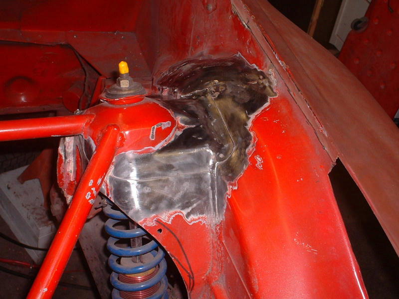
Posted by: URY914 Nov 20 2004, 09:07 PM
vvv
Attached image(s)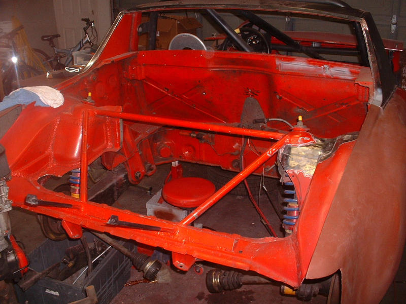
Posted by: URY914 Nov 20 2004, 09:09 PM
ee
Attached image(s)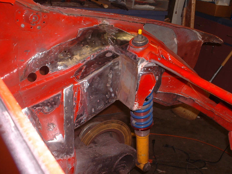
Posted by: URY914 Nov 20 2004, 09:12 PM
Before
Attached image(s)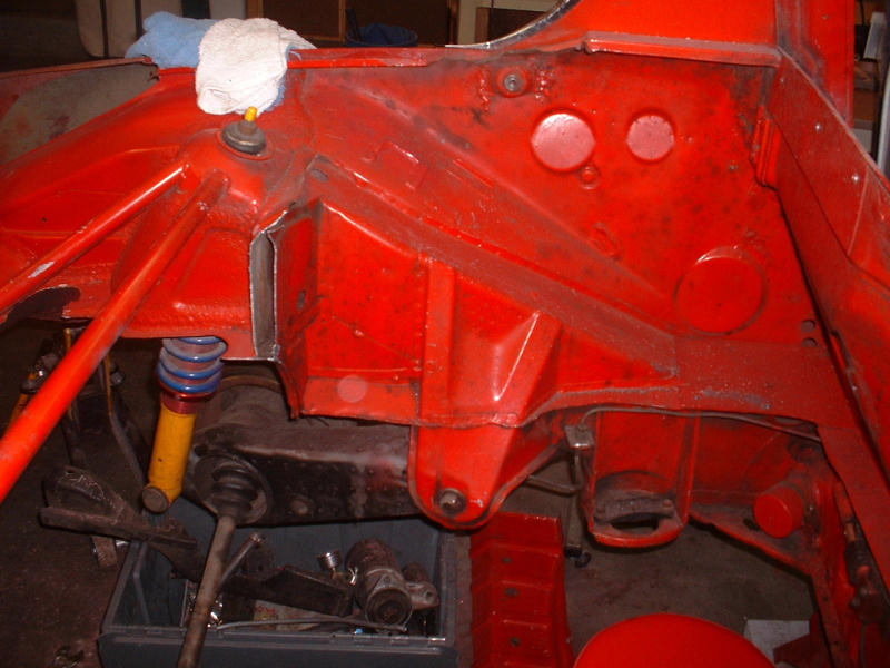
Posted by: Gint Nov 21 2004, 01:55 PM
Still waiting to hear from BRAD! with regard to my last question about "the cover".
Posted by: Brad Roberts Nov 21 2004, 02:01 PM
I'm looking it over right now.. hang on.
B
Posted by: Brad Roberts Nov 21 2004, 02:02 PM
I removed the "cover" on Chris Reales car a few months back. Hang on whilst I find the pics.
The frame rail is 3 sided with the cover on the outside.
B
Posted by: Gint Nov 21 2004, 02:10 PM
Gracias.
Need pics
Posted by: Brad Roberts Nov 21 2004, 02:24 PM
I dont have "arrows" I can use on this computer.
B
Posted by: Brad Roberts Nov 21 2004, 02:25 PM
OK. First off. The late cars have ribs and the early tubs dont. So be careful and KNOW what year tub pics your are looking at.
I'll revisit this tonight and explain more. I need to get cracking here at the shop.
B
Posted by: Gint Nov 21 2004, 02:43 PM
Please do.
L8R
Posted by: TimT Nov 21 2004, 07:28 PM
Hmmmmm Paul, you car weighed 15XX and you still had these panels in?
Damn and I though it was at light as it could be
Posted by: URY914 Nov 21 2004, 07:46 PM
Tim,
there is plenty more to come out
Stay tuned.
Paul
Posted by: Series9 Nov 21 2004, 08:13 PM
Here are some pictures of the tubing reinforcements I put in my car in an attempt to keep the 3.6 from folding the car in half. I also installed the factory stiffeners.
Attached thumbnail(s)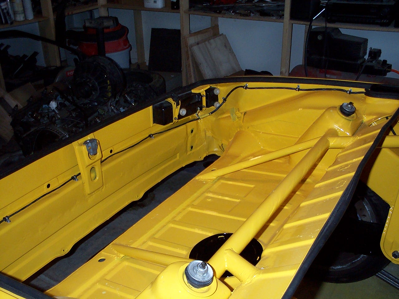
Posted by: Series9 Nov 21 2004, 08:14 PM
two..
Attached thumbnail(s)
Posted by: Series9 Nov 21 2004, 08:15 PM
three...
Attached thumbnail(s)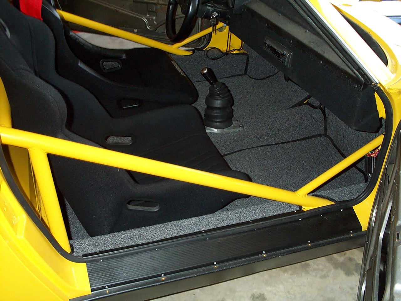
Posted by: URY914 Nov 21 2004, 08:51 PM
Very clean and nice, Joe. Good job.
I've always wondered if the strut from the ear foward is enough?
I'm thinking of running a bar to my rear tranny mount. It will run just over the axles.
Whata ya all think? Over kill?
Paul
Posted by: slivel Nov 21 2004, 09:05 PM
I've always wondered if the strut from the ear foward is enough?
I'm thinking of running a bar to my rear tranny mount. It will run just over the axles.
Whata ya all think? Over kill?
Paul
Paul, at 1524 lbs your car is very light and may benefit from the additional bracing to the trans mount. If it moves at all back there you may find binding when you need to shift gears (or find the wrong gear). That is why I added the bracing to my car.
Steve
Attached image(s)
Posted by: URY914 Nov 21 2004, 09:27 PM
I have added bars from the shock tower down to the tranny's sheet metal mounts (like everyone else)
.
But I''m in the prcess of cutting it all out and only having only strut bars from the shock towers and possibly from the tranny mounts forward to the rear of the ear.
Paul
Posted by: Series9 Nov 22 2004, 02:34 AM
I've always wondered if the strut from the ear foward is enough?
I'm thinking of running a bar to my rear tranny mount. It will run just over the axles.
Whata ya all think? Over kill?
Paul
No, I don't think it's overkill.
The tube you see from the ear to the firewall is not really backed-up sufficiently in my car. I did it because a local racer advised me to do so, but as I was putting it in, I did realize that, although it serves some purpose, it's less than perfect in its application.
Posted by: Jeroen Nov 22 2004, 04:29 AM
That's what I have in mind as well.
I also want to run braces from the center of the shock tower brace down to the suspension ears. That way, the ear will be fixed from 3 directions
Gonna trialfit the /6 first to double check clearance issues

Posted by: Jeroen Nov 22 2004, 04:30 AM
Joe, I just noticed you cut the rear end of the trunk floor out (above the muffler)
Why did you do that?
Posted by: URY914 Nov 22 2004, 08:05 AM
I want to stiffen the ear to the front (as seen in Joe's pic) and running by running to the rear. But I neet to put the engine back in to check clearances with the valve covers and axles.
I think you need to get the support struts down as close to the bottom of the ear as possible. Thats were the bending force is trying to move that ear.
I continue to work on mine just about every day so I'll be able to post some pics on what I'm planning to do.
Paul
Posted by: Series9 Nov 23 2004, 10:05 AM
Why did you do that?
It was a bad panel. I'm making an aluminum replacement that will hopefully say '914 RS' in the middle, similar to the alien symbol on Rick's /8, which was my inspiration.

Posted by: Gint Nov 24 2004, 08:36 PM
Anybody mind if I edit the title of this thread (more descriptive) and move it to Classics area?
Posted by: URY914 Nov 25 2004, 07:11 AM
I don't mind.
Posted by: Gint Nov 27 2004, 06:13 PM
We had a sawzall party yoday and I disected a frame rail. You can see where the frame tail is folded over and welded to the shock tower.
Attached image(s)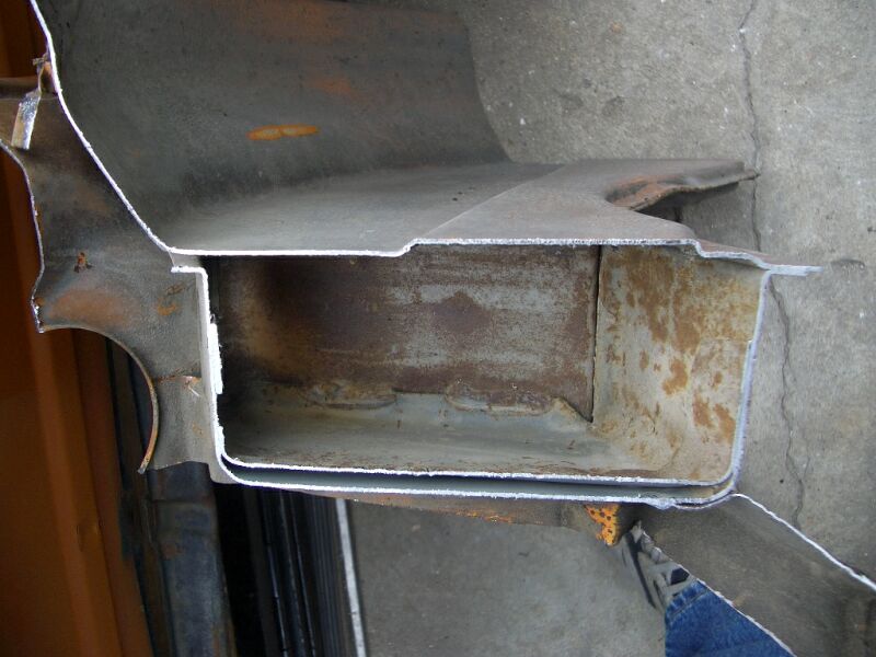
Posted by: Gint Nov 27 2004, 06:15 PM
This is the opposite side showing how the inner fenderwell is attached to the long or frame rail.
Attached image(s)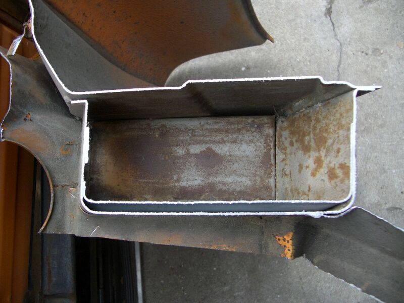
Posted by: Gint Nov 27 2004, 06:26 PM
I'm the proud owner of that section of tub, so if anyone wants a different view, just let me know.
I'll revisit this tonight and explain more. I need to get cracking here at the shop.
Still waiting ....
Posted by: Brad Roberts Nov 27 2004, 06:30 PM
That is ok. I'm still waiting to breath. I'm not at home right now, but I did get the home computer back online last night and I located the pics I wanted to show you.
Most of them are the same as what you showed.
What year tub was the silver car you cutup ?
B
Posted by: Gint Nov 27 2004, 06:31 PM
The one I just posted the pictures of was a 72 (02/72 build date) and was orange.
Posted by: Eric_Shea Nov 27 2004, 06:33 PM
Paitence Lil'Buckaroo. There's still plenty-o Broncs to bust. Festus has been busy
Posted by: Gint Nov 27 2004, 06:37 PM
To be specific, this is what I'd like to see pics of and hear more about.
Posted by: Brad Roberts Nov 27 2004, 06:38 PM
Ok. I know I have a ChrisR folder on my home computer. I'll try and post tonight from home. I'll be doing computer work all day today and tomorrow.
B
Posted by: Gint Nov 27 2004, 06:43 PM
Thanks Brad. Happy birthday BTW.
Posted by: Brad Roberts Nov 27 2004, 07:10 PM
Thanks Gint. Another year older and deeper in debt..LOL
B
Posted by: drew365 Nov 28 2004, 12:37 PM
Here's some pictures of the reinforcement done to my car by TRE here in North Hollywood. They connected the roll cage with the front and rear shock towers. Triangulated the shock towers to the tranny mount rail in the rear trunk. Connected the back of the suspension ear to the underside of the tranny mount rail, and added an adjustable toe brace to the front of the alingnment foot of the suspension.
Here's the cage to the front of the rear shock tower:
Attached image(s)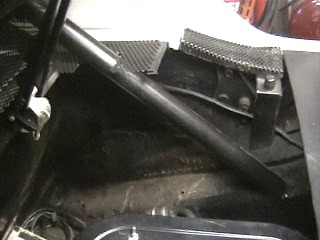
Posted by: drew365 Nov 28 2004, 12:39 PM
Triangulation in the rear trunk with larger rail at trans mounts:
Attached image(s)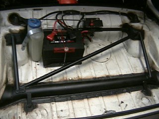
Posted by: drew365 Nov 28 2004, 12:41 PM
Underside of tranny mount rail to back of suspension ear, It's hard to get a good pic with engine and trans in the car:
Attached image(s)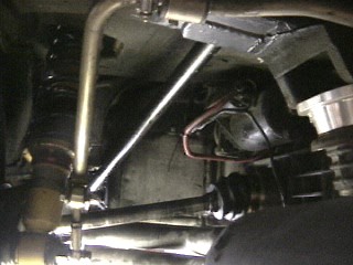
Posted by: drew365 Nov 28 2004, 12:43 PM
Adjustable toe reinforcement, again not a good angle for pic:
Attached image(s)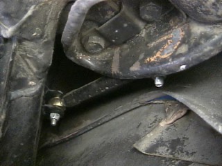
Posted by: drew365 Nov 28 2004, 12:44 PM
Front shock tower to cage:
Attached image(s)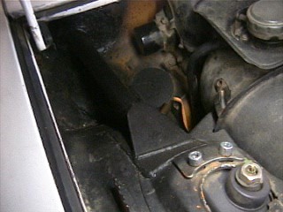
Posted by: drew365 Nov 28 2004, 12:51 PM
Same brace on the inside, there's also a brace about 18" up that connects down onto this one to triangluate this:
Attached image(s)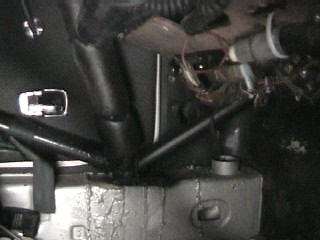
Powered by Invision Power Board (http://www.invisionboard.com)
© Invision Power Services (http://www.invisionpower.com)