Printable Version of Topic
Click here to view this topic in its original format
914World.com _ 914World Garage _ Testing engine on run stand
Posted by: mikea100 Jan 9 2012, 08:28 PM
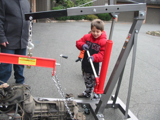
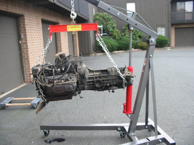
Yesterday, with some help from my 2 boys, I got my '76 2.0 short block on the engine run stand. I need help setting it up. It's late 2.0, complete, all stock, EFI. I'm looking for any info, any help at all. I've read few dozen threads about engine stands, but most of them deal with yokes, adapters and such. I need help with wiring and actually test running the engine. If local guys can stop by this long weekend and land me a hand, you'd really do me a solid and I'll return the favor. I'll serve beer of your choice. 
Thanks,
Mike
Attached image(s)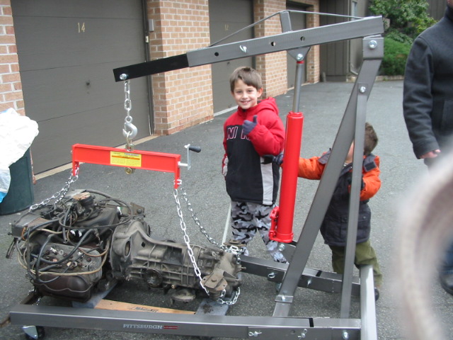
Posted by: Jeffs9146 Jan 9 2012, 09:24 PM
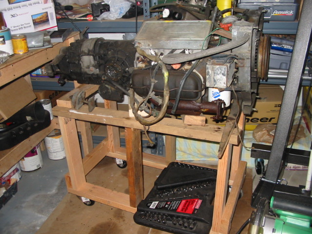
It looks like you used nails or screws to hold that together?  How long do you plan on running it?
I am not close so I cant come by but there is quite a bit of vibration from a running motor and you may want to at least run some bolts through those 2x4's!
Posted by: mikea100 Jan 9 2012, 10:35 PM

It looks like you used nails or screws to hold that together?
How long do you plan on running it?I am not close so I cant come by but there is quite a bit of vibration from a running motor and you may want to at least run some bolts through those 2x4's!
I used screws to hold it together. I want to run it for just few seconds as proof of concept. I will definitely reinforce it if I run it longer. I was checking out some diagrams and it seems that I'll need complete wiring harness (which I have), is that right?
Posted by: RobW Jan 9 2012, 10:40 PM
What are you testing?
Posted by: mikea100 Jan 10 2012, 05:56 PM
What are you testing?
I just want to make sure that engine runs before I put back in the car.
Posted by: Jeffs9146 Jan 10 2012, 06:22 PM
I have some engine run stand exhaust that you might be interested in!?
Attached image(s)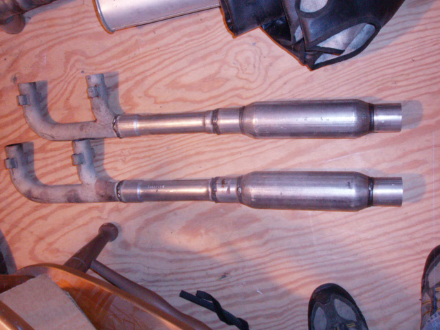
Posted by: windforfun Jan 10 2012, 07:24 PM
Too bad Thomas isn't around to help. Sorry, I couldn't resist after seeing your address.
Posted by: Vacca Rabite Jan 10 2012, 08:42 PM
Actually, as long as you have the engine like that, mount the regular exhaust. Then you can put the whole package in the car.
This is a great exercise. It is a lot easier to find oil leaks with the engine out of the car, and it is way easier to find exhaust leaks too.
This was the stand I build for my engine: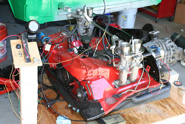
Its low to the ground, and on wheels, with a slot in the middle for a jack. When I am done testing, I just roll the whole thing under the car for install EASY! The "Dash" is just a push button for the starter and a switch for the ignition and fuel. For FI I might have to add a few more circuits. I did it like this so I could run the starter to build oil pressure, test compression, etc, without having the fuel or spark firing. The tack is there for cam run in, to make ssure I don't let the idle under 2000 rpm for the 20 minute run in.
Zach
Posted by: mikea100 Jan 10 2012, 09:26 PM
Actually, as long as you have the engine like that, mount the regular exhaust. Then you can put the whole package in the car.
This is a great exercise. It is a lot easier to find oil leaks with the engine out of the car, and it is way easier to find exhaust leaks too.
This was the stand I build for my engine:
Its low to the ground, and on wheels, with a slot in the middle for a jack. When I am done testing, I just roll the whole thing under the car for install EASY! The "Dash" is just a push button for the starter and a switch for the ignition and fuel. For FI I might have to add a few more circuits. I did it like this so I could run the starter to build oil pressure, test compression, etc, without having the fuel or spark firing. The tack is there for cam run in, to make ssure I don't let the idle under 2000 rpm for the 20 minute run in.
Zach
Zach,
You’re right, it is a great exercise. I will be backdating exhaust using SSI HE, that's why I built the stand high like that for easy access. I think that for running FI I will need to connect the relay board somehow. I will probably use the main harness. I'm not sure that I'll be able to wire starter and fuel/fire separately like you did, I'll try though as I think that it's a great idea. What king of ignition switch and push botton start did you use?
Thanks,
Mike
Posted by: Vacca Rabite Jan 10 2012, 10:49 PM
I used the cheapest push button starter switch I could find from Autozone that would handle 40+amps for the starter, and whatever 2 position switch my hands found first for the fuel and spark.
Zach
Posted by: jcd914 Jan 11 2012, 02:49 AM
Add to your engine stand a place to hang your FI computer, MPS and relay board. Pull your relay board from your car (or if you have a spare use it) and plug all the engine wiring in just like it was in the car. Hang the FI computer and mount the MPS and hook it up. You need the fuel pump off the car or a spare, some thing to serve as a fuel tank (I used a my lawn mower fuel can) and some hose to plumb it in and a battery. Now all you have to do is add a couple switch to get power to the relay board and the starter and some wiring to the fuel pump.
You'll have to look over a wiring diagram and figure out the wiring connections you need but they will all go to the 14 pin connector at the relay board except the main battery cable that need to go to the start and to the engine or trans case.
I just set my engine on jack stands (seem like the right thing for a 914 engine), 1 under each end of the engine cross bar and 1 under the tail end of the trans. Then I made a little stand to hold the relay board and some switches. Just layed the FI computer and MPS on top of the engine, a bit sloppy but it worked.
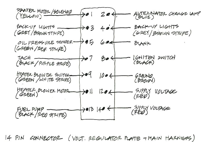
Here is what I have for the 14 pin connector for the Relay Panel.
1 - Power in from starter switch
2 - Power/ground for Alternator light
3 -
4 -
5 - From Oil Press Light
6 -
7 - Signal to Tach
8 - Power in from Ignition switch
9 - To Heater Fan Switch
10 - To Main Ground
11 - Power out to Heater Fan
12 - Power in from Battery
13 - Power out to Fuel Pump
14 - Power in from Battery
Jim
Posted by: mikea100 Jan 17 2012, 11:26 PM
First of, please be patient with me as I'm new at this and will ask for help.
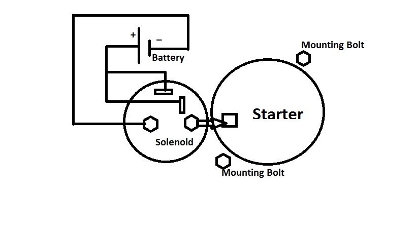
I'm just going to go down the list. Solenoid (starter) has a heavy black wire (probably gauge 4) going to the battery + terminal. Where do I connect the power from switch? I'm assuming that it goes to light spade connector, correct?
Attached image(s)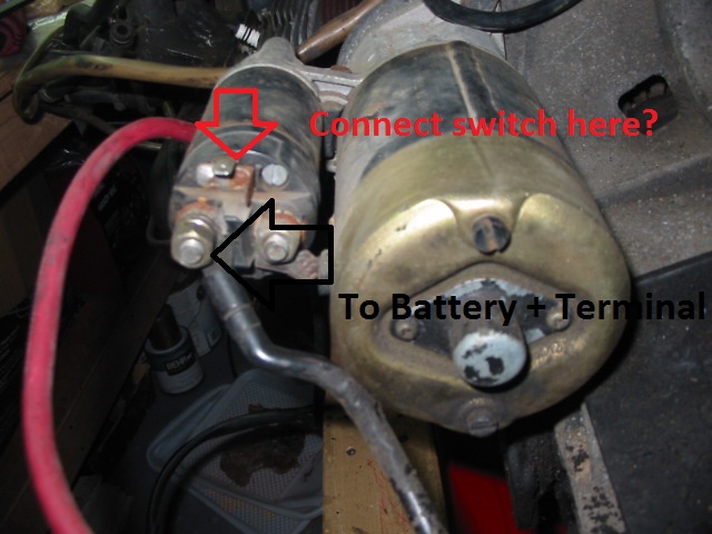
Posted by: dlee6204 Jan 18 2012, 12:09 PM
Correct
Posted by: Dave_Darling Jan 18 2012, 12:28 PM
You'll need power to the coil.
You'll need to provide 29 PSI fuel to the fuel rail, and provide a place to dump the fuel coming out of the pressure regulator.
You'll need to supply power to the EFI through the 4-pin connector. I think two of the pins get power and two get the starter wire signal; double-check the relay board diagram on that though.
You'll need to ground the case to the battery.
You'll want a way to hold the engine onto the stand.
You might want to hook up a light to the oil pressure sender. A bulb with +12V on one side and the other connected to the sender should be good enough. If you have a mechanical oil pressure gauge you're using, you can ignore the light.
I can't think of anything else off the top of my head.
--DD
Posted by: jcd914 Jan 18 2012, 05:48 PM
The connector pin list I posted was inputs/outputs for the 14 pin connector on the fuse/relay panel. I found it easier to connect the original engine harness to the fuse/relay panel, then there are just a few connections to be made at the 14 pin connector to the panel.
Here is what I have for the 14 pin connector for the Relay Panel.
1 - Power IN from starter switch
2 - Power/ground for Alternator light
3 -
4 -
5 - From Oil Press Light
6 -
7 - Signal to Tach
8 - Power IN from Ignition switch
9 - To Heater Fan Switch
10 - To Main Ground
11 - Power out to Heater Fan
12 - Power IN from Battery
13 - Power OUT to Fuel Pump
14 - Power IN from Battery
Jim
Posted by: mikea100 Jan 22 2012, 06:28 PM
I'm having trouble with this seemingly easy task. I tried set up above with no luck. I then studied electrical diagrams on Pelican and changed the set up and still no luck.
Picture 1 shows set up #1 as desribed above - power from battery to the big left terminal and 2 small spade terminals. Picture 2 shows setup #2, as I understood it from diagram, power to 2 small spade terminals and ground to the big terminal.
Link to the pelican's diagram
http://www.pelicanparts.com/914/parts/Electrical/914_electric_74E.jpg
Any help is greatly apreciated.
Attached image(s)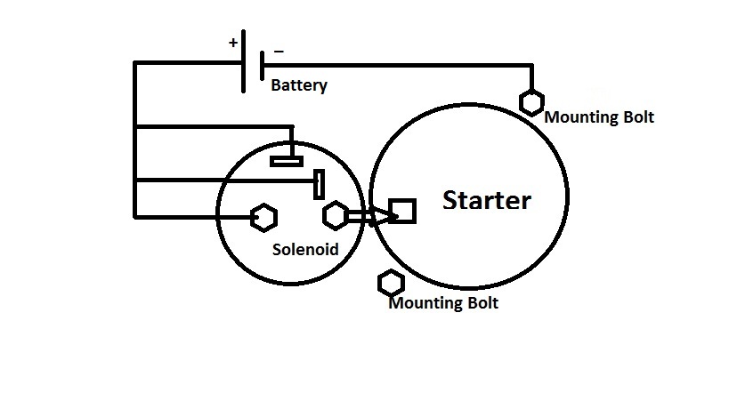
Posted by: Dave_Darling Jan 22 2012, 07:14 PM
The battery + should connect to the big post on the solenoid. The first pic has that right. The battery - would connect to the mounting bolt as in the first pic as well.
The flags on the back of the solenoid are electrically the same thing as each other. You connect one (any of them) to the battery + when you want the starter to crank.
--DD
Posted by: PRS914-6 Jan 22 2012, 09:04 PM
Posted on this thread as well: Ready for break in- need additional info
Personally I would not run a new engine unloaded for that length of time. The cam is not the only thing to break in. The cam manufacturers want their ass covered and they could care less about any other engine component as long as they don't have to warranty the cam. Rings are also critical in the first hour of running. If you don't put the engine under a load quickly the rings will not likely seat as fast as you would like or perhaps forever. Steady RPM being the worst.
When you load an engine, gas pressure increases, goes behind the rings and increases the ring to cylinder wall pressure. This pressure is critical for sealing and is also critical that the pressure takes advantage of the sharp honing in the cylinder and to break in the rings. The cylinder walls quickly "glaze" after the engine is fired up, friction is lost and you are stuck with whatever you got. Every engine component has a special need for break in....don't focus on just one. Some engines get assembled with NO OIL ON THE RINGS to aid this.....it's that critical.
My recommendation is to fire it up, get it quickly on the road and load/unload...load/unload A good way to do this is stay in second or third gear....step on it hard, let it rev and get off it....cruise (to cool) and repeat 10 times and allow to fully cool....Start over
I have seen far more people ruin a new engine (usually a smoker) from loving it than driving it like you stole it.
Everyone has a different opinion on break-in so YMMV....good luck
Posted by: mikea100 Jan 23 2012, 10:54 AM
The battery + should connect to the big post on the solenoid. The first pic has that right. The battery - would connect to the mounting bolt as in the first pic as well.
The flags on the back of the solenoid are electrically the same thing as each other. You connect one (any of them) to the battery + when you want the starter to crank.
--DD
Thank you Dave. I got Cranky! The ground connection was loose, once that was taken care of, everything fell into place.
Posted by: mikea100 Jan 23 2012, 11:05 AM
Posted on this thread as well: Ready for break in- need additional info
Personally I would not run a new engine unloaded for that length of time. The cam is not the only thing to break in. The cam manufacturers want their ass covered and they could care less about any other engine component as long as they don't have to warranty the cam. Rings are also critical in the first hour of running. If you don't put the engine under a load quickly the rings will not likely seat as fast as you would like or perhaps forever. Steady RPM being the worst.
When you load an engine, gas pressure increases, goes behind the rings and increases the ring to cylinder wall pressure. This pressure is critical for sealing and is also critical that the pressure takes advantage of the sharp honing in the cylinder and to break in the rings. The cylinder walls quickly "glaze" after the engine is fired up, friction is lost and you are stuck with whatever you got. Every engine component has a special need for break in....don't focus on just one. Some engines get assembled with NO OIL ON THE RINGS to aid this.....it's that critical.
My recommendation is to fire it up, get it quickly on the road and load/unload...load/unload A good way to do this is stay in second or third gear....step on it hard, let it rev and get off it....cruise (to cool) and repeat 10 times and allow to fully cool....Start over
I have seen far more people ruin a new engine (usually a smoker) from loving it than driving it like you stole it.
Everyone has a different opinion on break-in so YMMV....good luck
Paul, thank you for the advice, but I'm not trying to break in new/rebuilt engine. I have a 2.0 engine in unknown condition and trying to determine what it needs to make it run.
Posted by: ape914 Jan 23 2012, 12:54 PM
just put it in the car, 914's are blessed with quick and easy engine install. If you didn't have to fool with the test stand, the engine could be running by now in your car. This is a waste of time and effort in my opinion.
Posted by: mikea100 Jan 24 2012, 02:02 PM
The battery + should connect to the big post on the solenoid. The first pic has that right. The battery - would connect to the mounting bolt as in the first pic as well.
The flags on the back of the solenoid are electrically the same thing as each other. You connect one (any of them) to the battery + when you want the starter to crank.
--DD
David,
What do the numbers inside wires mean in the electrical diagram? I see decimal numbers 0.5, 1.0, 1.5 as well as whole numbers (integers) 10, 15, 20 etc. I thought that those were tickness of the wire (gauge), but after I traced some of them that theory is clearly wrong.
Thanks,
Mike
Posted by: Dave_Darling Jan 24 2012, 03:57 PM
The decimals should be the thickness of the conductor, not the whole wire with insulation.
The whole numbers may be at the ends of the wire only, and should denote the connections at a certain component. Usually there are numbers cast into the part which will match up with those numbers on the diagram. ... Oh, on the early diagram they are generally inside the outline of the component, that helps.
Example of the 70-73 type of diagram:
http://www.pelicanparts.com/914/parts/Electrical/914_electric_73A.jpg
On those diagrams, there is another type of number. That is used when a wire goes somewhere and ends; there will be a number there. The wire continues on the other page of the diagram, and you need to look for that same number to see where on the diagram the wire continues. On the left side of that diagram above, you can see a red wire with an "11" next to it. That wire continues on the other page of the diagram here:
http://www.pelicanparts.com/914/parts/Electrical/914_electric_73C.jpg
(Yeah, it's a bit lost in the other wires in the area, but the 11 is there.)
Oh, and of course there are the numbers in circles on the early diagram which are the labels telling you what the part is. You look that number up on the key. For instance, #60 is the fuse block.
--DD
Posted by: mikea100 Jan 26 2012, 11:30 PM
I traced most of the 12 pin connections, but some connections I can't fugure out for the life of me. Please correct/fill in the blanks.
T12-1 - Power to Oil Pressure Switch
T12-2 - Power To Backup Light Switch
T12-3
T12-4 - Left/Right Backup Light
T12-5 - Ignition Condenser
T12-6 - Power from Ignition Switch, I think that this is connected to the flags on the solenoid, connecting one to the battery + when cranking starter. It also connects to ECU 4 pin T4-II and T4-IV.
T12-7 - Ignition (Coil Terminal 1?)
T12-8
T12-9
T12-10/11 - Power to Heater Blower
T12-12 - Suplementary Air Valve (what is it? where is it?)
Thank you guys for helping me with this project.
Posted by: Dave_Darling Jan 27 2012, 04:48 PM
The connections vary a little from year to year.
For 1974+ (which I am most familiar with), they go:
1= oil pressure light sender
2 = backup lights
3 = not connected
4 = backup lights
5 = tach signal wire (goes to points connection on coil)
6 = starter signal to solenoid
7 = ignition power to coil
8 = not connected
9 = not connected
10 = GREEN (on my car) wire that loops to pin #11 in the same connector
11 = looped wire to #10
12 = power to Auxiliary Air Regulator; powered by the fuel pump circuit
AAR is a vertical can to the left-front of the manifold; it has two hoses coming out of the top part and a single wire plugged in at the bottom. It provides a higher idle when the engine is cold.
--DD
Posted by: mikea100 Jan 28 2012, 10:41 PM
Thanks Dave.
I finally got a compression gauge and did the test. The numbers are pretty bad especialy #1. I'm pretty bummed out about it. The engine hasn't run since 2001, so tomorrow I'll try to adjust valves and repeat the test. I'll also make sure that the throttle wide open. The intake valve is on the left side, correct?
#1 - 40psi
#2 - 70psi
#3 - 70psi
#4 - 70psi
Posted by: Dave_Darling Jan 28 2012, 11:14 PM
Intakes are the middle valves, exhausts are the outer ones. Notice where the intake manifold bolt up to the heads; the intake valves are there. The exhaust manifold bolts to the heads right under where the exhaust valves are.
Cold compression numbers are not going to be as good an indication as warm; they usually read low.
--DD
Posted by: mikea100 Jan 29 2012, 08:26 PM
I did the valve adjustment today and remeasured. I feel a lit bit better about #1, may be it is alive. Now if I could only find my MPS and decel valve to complete the setup  .
.
#1 - 65psi (was 40psi)
#2 - 80psi (was 70pis)
#3 - 70psi (was 70pis)
#4 - 70psi (was 70pis)
Posted by: Jon Fernandes Jan 30 2012, 11:18 AM
Mike, I may have an MPS accessible in my mess of a garage. You can borrow it if you cant find yours. You can swing by and pick it up this week sometime if you'd like.
Posted by: mikea100 Jan 30 2012, 12:30 PM
Mike, I may have an MPS accessible in my mess of a garage. You can borrow it if you cant find yours. You can swing by and pick it up this week sometime if you'd like.
Sweet, thanks Jon. I'll txt you. I took bunch of parts bubble wrapped them and put them somewhere safe, now I can't find them
 .
.
Posted by: ruddyboys Jan 30 2012, 04:09 PM
I am going to try this in a few weeks. 1st question, I understand the wiring to the starter, Can I put a lead from the battery (possibly with a toggle sw) to the + post on the coil to give power to the dizzy? The PO removed the relay board so wiring is a nightmare
Posted by: Vacca Rabite Jan 30 2012, 06:22 PM
I did the valve adjustment today and remeasured. I feel a lit bit better about #1, may be it is alive. Now if I could only find my MPS and decel valve to complete the setup
.#1 - 65psi (was 40psi)
#2 - 80psi (was 70pis)
#3 - 70psi (was 70pis)
#4 - 70psi (was 70pis)
Was the engine warm and the throttle wide open when you did these?
If so, those are terrible numbers. You want to see a minimum of ~95 psi, and at 90 you start buying what you need for a rebuild.
If the engine was cold, the numbers should come up some when it is warm, but I don't know that they would come up 30 psi.
Zach
Posted by: nathansnathan Jan 30 2012, 07:06 PM
Also you want to make sure all the spark plugs are out, I didn't know that at 1 point, or that an overlap cam will cause low compression test readings..
It's actually not that reliable, the actual numbers, in a compression test. A gauge I had about 1 1/2 years from autozone started cutting numbers in half; low readings. I've got another gauge, a Sa-on, hopefully somewhat better.
Also, I wouldn;t tust this "oil makes it better, it's the rings". I've been able to get the pressure up with oil, pull the head and the valves fail a spirits test.
Personally I wouldn't be doing compression tests warm. It's easy to gall the aluminum threads in the head, and end up pulling all the threads right out. The right tool to fix that is abot $200 and god help you if it's #2 or 4.
I suppose it's nice to have it on the run stand at that point rather than in the car.  Good luck, been watching the thread, gonna make my own run stand sometime.
Posted by: mikea100 Jan 30 2012, 08:04 PM
The engine was cold, I don't believe that it has run since 2001 (at least that was the registration sticker on the car when I bought it). The throttle was wide open. I used Actron comression gauge and it was brand new. Tomorrow I'll redo the test w/ spark plug out.
http://www.amazon.com/Actron-CP7828-Professional-Compression-Storage/dp/B00020BM28
Posted by: mikea100 Jan 31 2012, 09:35 AM
I am going to try this in a few weeks. 1st question, I understand the wiring to the starter, Can I put a lead from the battery (possibly with a toggle sw) to the + post on the coil to give power to the dizzy? The PO removed the relay board so wiring is a nightmare
This is stock wiring of coil for D-Jet (1.7 and 2.0):
1) Green wire connects Condencer to Points to Terminal 1 (-) on Coil
2) Main harness has 2 wires branched out - black and purple. The black one connects to Terminal #15 (+) and the purple wire connects to Terminal 1 (-).
You can hot wire battery (+) to Terminal 15 (+). I believe that you MUST disconnect Green and Purple from Terminal 1 (-). IIRC that's how they test ignition switch.
Posted by: ruddyboys Jan 31 2012, 03:08 PM
The black purple goes to the tach, so I wont be needing that at first. The green goes to the condenser, I have electronic ignition so no need for points or condenser.
Posted by: Dave_Darling Jan 31 2012, 05:26 PM
There is no purple wire on the coil that I am aware of.
There are two black wires, one of which is thicker than the other. The thicker one probably has a red stripe on it, and gets +12V when the ignition is on. That one goes to the coil (+) terminal.
The thinner one has a purple stripe, and carries the tach signal. It connects to the coil (-) terminal, just like the wire from the points/condensor does.
The red and purple both fade, so they can be a bit difficult to tell apart. That's why I mention that the one is thicker than the other.
--DD
Posted by: mikea100 Jan 31 2012, 09:21 PM
I have great news to report. I did as Nathan suggested - cold engine, throttle open, all spark plugs out and the numbers came in excellent.
#1 - 120psi (was 65psi)
#2 - 115psi (was 80pis)
#3 - 115psi (was 70pis)
#4 - 125psi (was 70pis)
I also charged battery for 24hr, so starter was spinning a lot livelier.
There are two black wires, one of which is thicker than the other. The thicker one probably has a red stripe on it, and gets +12V when the ignition is on. That one goes to the coil (+) terminal.
The thinner one has a purple stripe, and carries the tach signal. It connects to the coil (-) terminal, just like the wire from the points/condensor does.
The red and purple both fade, so they can be a bit difficult to tell apart. That's why I mention that the one is thicker than the other.
--DD
Hmm, I mine are solid black and solid purple w/ same width. PO warned me that car had electrical problems, maybe those wires were replaced.
Posted by: mikea100 Feb 24 2012, 10:33 PM
I've had no luck in getting this engine running. I get weak spark or no spark at all. I replaced spark plugs, wires, dist cap, coil, points, condenser. The central wire on the coil has good juicy spark, but 1 cyl gets very weak spark. Coil is hotwired and gets 12.8V between terminals 1 and 15, tach wire unplugged. Any suggestions are greatly appreciated.
Also, while we're on the subject, I've read "Ignition Troubleshooting Checklist" on the Pelican site and it says that "the primary coil windings should give reading of 0.3-0.6 ohms. Secondary coils should be near 600 ohms". Is the primary coil winding between terminal 1 and 15? What is the secondary winding?
Posted by: Al Meredith Feb 25 2012, 10:27 AM
Whenever I build an engine I run it on my engine stand. I use a single 32/36 weber to test run at first. That way I don't have to be concerned with FI problems or carb syncing. I can also use a cheap electronic "clicker" fuel pump. I also use a direct reading oil pressure guage.
Posted by: Prospectfarms Feb 25 2012, 10:43 AM
Yesterday, with some help from my 2 boys, I got my '76 2.0 short block on the engine run stand. I need help setting it up. It's late 2.0, complete, all stock, EFI. I'm looking for any info, any help at all. I've read few dozen threads about engine stands, but most of them deal with yokes, adapters and such. I need help with wiring and actually test running the engine. If local guys can stop by this long weekend and land me a hand, you'd really do me a solid and I'll return the favor. I'll serve beer of your choice.
Thanks,
Mike
Loved the photos of the boys helping and chuckled when I saw your run-stand. Looks like something I would build. Looking forward to see whether your mission is accomplished. Thanks to the various posters for other information.
Posted by: Tom Feb 25 2012, 10:57 AM
Did you hook up your relay board? That is needed to tell the fuel pump when to turn on and the ECU power comes from the relay board.
If possible, give us a simple drawing of what you have now and we can get you in the right direction.
Common problem when testing like this is too small of a ground wire to battery. Need something large! If you have a good set of jumper cables, use one of them from batt negative to trans case.
Tom
Posted by: mikea100 Feb 25 2012, 07:08 PM
Tom,
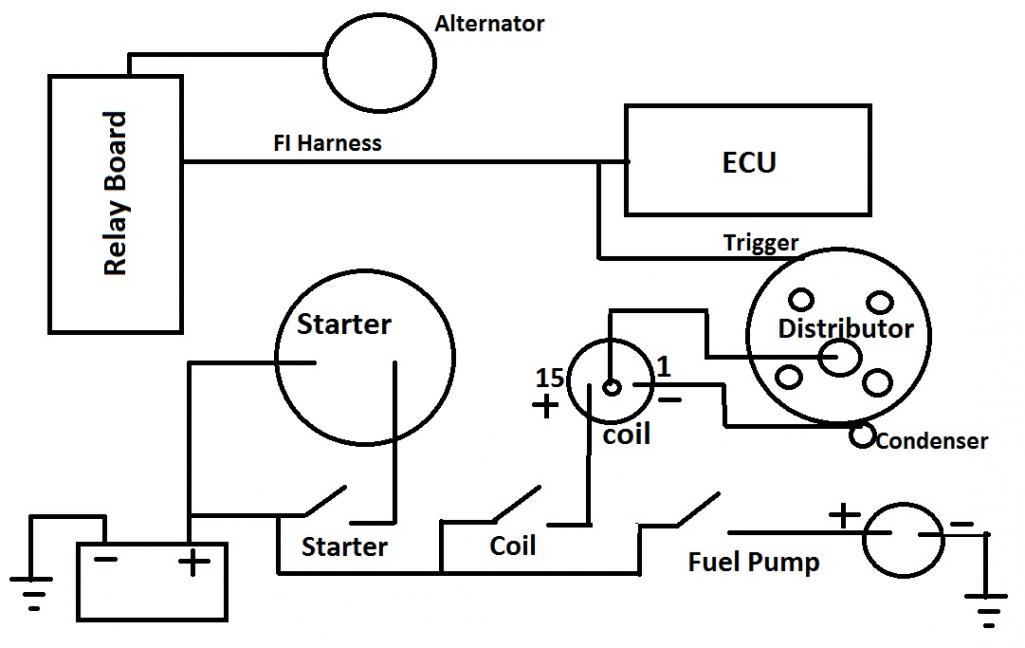
The relay board is hooked up, however, I have fuel pump and coil hotwired. I have a simple dashboard w/ 3 switches: 1 - push button controls starter, 2 and 3 - toggle switches control coil and fuel pump respectively. FI harness all hooked up - all injectors, MPS, TPS, temp sensors, cold start valve etc. Alternator is connected to the relay board as well. Ignition harness is partially connected, but I don't really need it as I can control starter and coil w/o it. I'm attaching a basic diagram of the setup.
It actually works and I can control starter, coil and fuel pump. I'm having difficulties with getting spark in cyl 1. Coil has good spark, but 1 cyl is very weak spark. Once I figured out that spark is the problem I stopped turning on the fuel pump and only use starting fluid in throttle body.
Thank you,
Mike
Did you hook up your relay board? That is needed to tell the fuel pump when to turn on and the ECU power comes from the relay board.
If possible, give us a simple drawing of what you have now and we can get you in the right direction.
Common problem when testing like this is too small of a ground wire to battery. Need something large! If you have a good set of jumper cables, use one of them from batt negative to trans case.
Tom
Attached thumbnail(s)
Posted by: Tom Feb 26 2012, 07:46 AM
It looks like you are not getting power to the ECU. If you are getting spark, there is no reason why it shouldn't at least fire on some of the cylinders.
It looks like you have the fuel injestion harness hooked up, but are not switching power thru the relay board which is where the ECU is powered from. I think that would be pin 1 of the 4 pin connector
You need to provide power to pins 12 and 14, then switched power to 8 and a ground to 10, all on the 14 pin connector. I think that would get power to the ECU.
Tom
Posted by: Prospectfarms Feb 26 2012, 09:37 AM
It looks like you are not getting power to the ECU. If you are getting spark, there is no reason why it shouldn't at least fire on some of the cylinders.
It looks like you have the fuel injestion harness hooked up, but are not switching power thru the relay board which is where the ECU is powered from. I think that would be pin 1 of the 4 pin connector
You need to provide power to pins 12 and 14, then switched power to 8 and a ground to 10, all on the 14 pin connector. I think that would get power to the ECU.
Tom
I hope you don't mind my adding some diagrams, but if I ever build my own run-stand one day, this thread would be a handy reference for the electrical hook-up.
Relay board diagrams (courtesy: Jeff Bowlsby)
4pin connector on relay board:
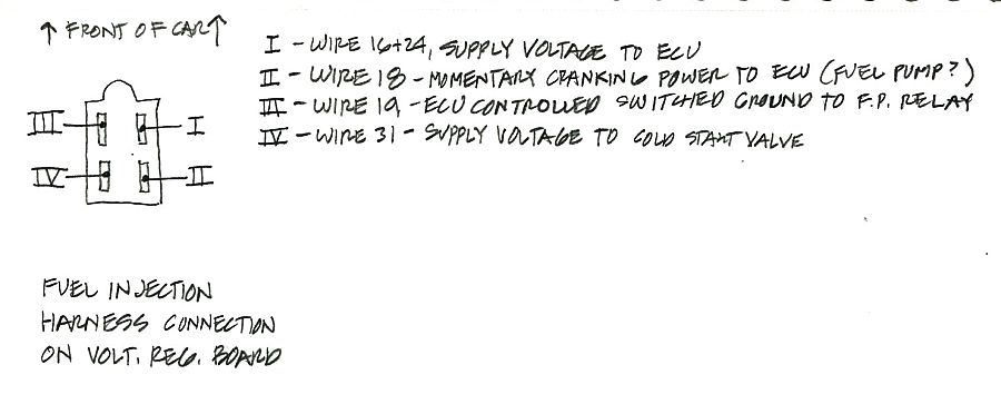
regulator board terminal functions:
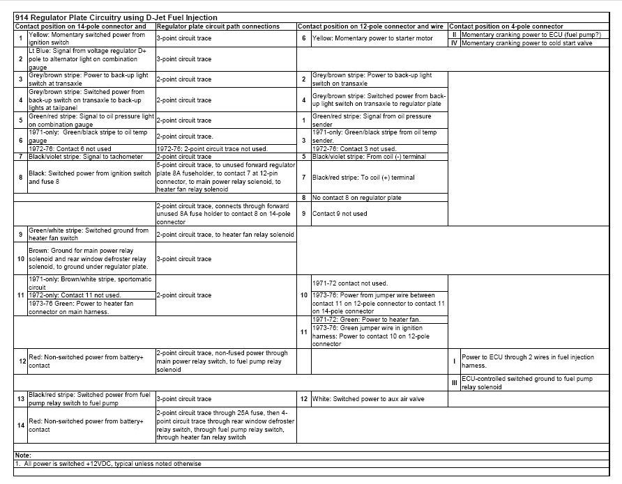
Regulator board diagram:
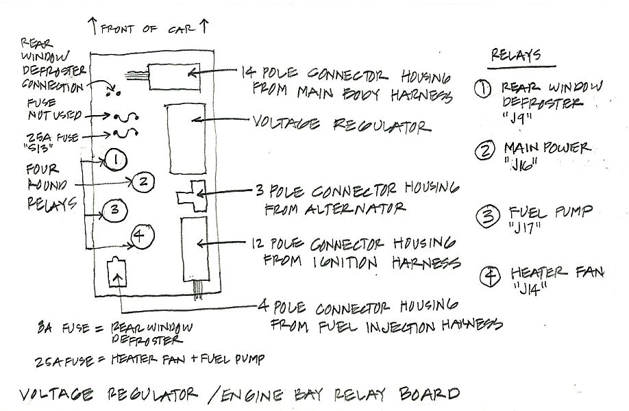
14 pin connector diagram:
Posted by: Tom Feb 26 2012, 10:09 AM
Wow Stuart,
Those are great diagrams. Thanks Jeff! I have to figure out how to save them so I can get to them easily!
Tom
Posted by: mikea100 Feb 27 2012, 08:05 PM
Thank you guys, those diagrams are great. My alternator and its harness along w/ relay board are definitely suspects that's why I hotwired fuel pump. I was hoping to completely bypass alternator. But even if ECU doesn't get power it still doesn't explain why there's no spark. My next step is to check and adjust the points. Also, correct me if I'm wrong, but it sounds like if pins 12 and 14 get power, pin 10 gets -grnd - that will completly bypass relay board.
Posted by: Tom Feb 27 2012, 08:54 PM
mikea100,
Pins 12 and 14 are the power to the relay board, pin 10 is ground. When you jump power to pin 8, this operates the power relay and provides power to the fuel pump relay and ECU. When the ECU gives a ground to the fuel pump relay, it is energized, giving power to the fuel pump and AAR ( aux air regulator).
Here is a pic/dia of the relay board that may help.
Tom
Attached image(s)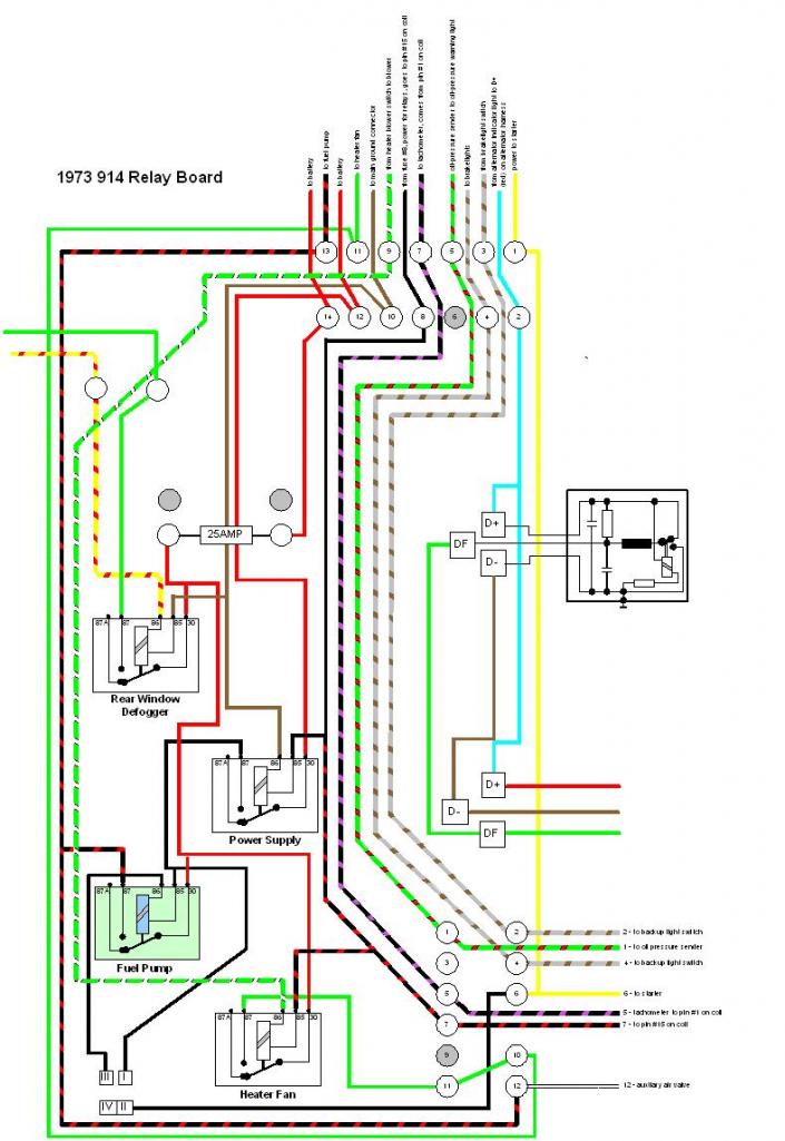
Powered by Invision Power Board (http://www.invisionboard.com)
© Invision Power Services (http://www.invisionpower.com)