Printable Version of Topic
Click here to view this topic in its original format
914World.com _ 914World Garage _ Need help with my 2.0
Posted by: ChristopherB Apr 2 2012, 06:27 PM
I bought my 914 last summer and have some problems. Everything I know, which is not much, I have learned reading this great forum since then. I was looking for a fun affordable Sunday driver. I love the look of my car, and it is great to drive. However, I started having problems from day one, and the engine is coming out this week for further examination/ rebuild.
Here is the info on the engine from the PO who did a rebuild about 6K miles ago.
2.0 with original D-Jet
Web Racing FI Cam with hydraulic lifters and push rods
Big Bore throttle body from High Performance House
Heated O2 sensor with air/fuel gauge
original heads rebuilt with new valves ported and polished
case steam cleaned and align bored
Remote sender for oil pressure
Mahle pistons , new rings and sleeves
There are a lot other items done to the car unrelated to my engine woes. You can see the ad here: http://www.914club.com/bbs2/index.php?showtopic=269159
My problems are numerous.
A local shop tells me cylinders 1&3 have low compression and engine needs a rebuild.
This sucks but I am resigned to the fact and am preparing to take on the challenge with a neighbor. I am preparing the engine for removal and it will be out within a week.
The PO indicated that the vac unit on the dist was not working. His mechanic had it tuned with the vac line going to the advance side when it should be on the retard side. I tried switching it but the car would not idle without stalling.
The car has very high crankcase pressure on start up and blew the cooler or the seals 2 weeks ago. The car has oil leaking from the push rod tubes even though the seals were replaced recently. Front main seal is leaking. Pretty much everywhere.
I am confused about cylinder and piston choices and sizes. What is what? Is a 2.0 engine 2056cc and not 2000? And what would be good in my application? I would like to get 140HP if I am going to do a rebuild.
Can I eliminate the stock cooler, and run only a remote cooler?
I have spent a lot of time reading build threads and searching remote coolers, but at this point it seems daunting.
I just purchased the following from a member here;
"Stock distributor from my 73 2.0L with functioning vac advance, Crane XR3000 electronic ignition, MSD rev limiter, Crane Fireball LX91 ignition coil, cap and rotor".
Should I start by purchasing the Raby rebuild video?
I am really bummed to have these problems with what I thought was a solid car, and am really bummed I am not enjoying the nice weather.
I am located in Towson, Maryland if anyone wants to recommend shops, mechanics, or better yet offer help or services.
Posted by: struckn Apr 2 2012, 06:59 PM
Chris I just sent you a PM with some info on local shops. Check you messages.
Doug

Posted by: ChristopherB Apr 2 2012, 07:02 PM
Thanks Doug
Posted by: Dave_Darling Apr 2 2012, 08:56 PM
The Raby video is a good guide to a rebuild that has no surprises and a team of elves who clean and measure everything for you. Very worthwhile.
The Haynes manual is a pretty good resource. Tom Wilson's "How to Rebuild Your Volkswagen Air-Cooled Engine" is also a good resource. Wilson talks about some of the cleaning/measuring/machining that happens to the parts as well, which is nice. He talks about the Type I/II/III/IV and 914 engines all together, which can be confusing.
The stock "2.0" displacement is actually 1971cc. That's a 71mm stroke and a 94mm bore. If you go up to a 96mm bore, you get a 2056cc engine.
--DD
Posted by: euro911 Apr 2 2012, 09:47 PM
I would get a second opinion (from a knowledgeable bud or local member in good standing on this forum) before doing a tear-down and rebuild.
Do a valve adjustment first, then perform a compression check and leak-down test.
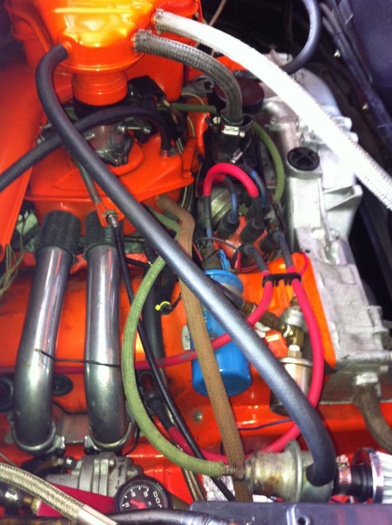
As for positive crankcase pressure, in looking at the pix of the engine, I see NO crankcase venting whatsoever. The oil filler breather box vent is plugged. It needs to be vented out to an external breather box at a minimum. Additional venting from the heads may be required as well 
Tackle these issues first and post your findings. Then you can move on to the distributor and timing issues.
EDIT: I do see venting in another pic with the air filter housing installed. It may not be enough though ... still may need to vent the heads (can be done with aftermarket nipples on the valve covers if you don't want to remove the heads right now).
Posted by: 914itis Apr 2 2012, 10:12 PM

I would get a second opinion (from a knowledgeable bud or local member in good standing on this forum) before doing a tear-down and rebuild.
Do a valve adjustment first, then perform a compression check and leak-down test.
As for positive crankcase pressure, in looking at the pix of the engine, I see NO crankcase venting whatsoever. The oil filler breather box vent is plugged. It needs to be vented out to an external breather box at a minimum. Additional venting from the heads may be required as well
Tackle these issues first and post your findings. Then you can move on to the distributor and timing issues.
EDIT: I do see venting in another pic with the air filter housing installed. It may not be enough though ... still may need to vent the heads (can be done with aftermarket nipples on the valve covers if you don't want to remove the heads right now).

I had a similar experience with my 1st 914' a local mechanic told me to start pulling the heads. Turned out that the engine only needed valve adjustment, dwell strings and carb sync. Until now, it runs great.
Same story from pO , then engine was rebuilt less than 100 miles prior to my purchase.
Posted by: ChristopherB Apr 3 2012, 12:18 PM
Thanks everyone so much! I have all the parts to vent the heads by installing ports on the valve covers and installing a breather can. I was going to do this and then the cooler blew. Thanks for the help. The PO also mentioned that the iron melling pump is known to cause high pressure on start up. Is this something I should change at this point to the aluminum schadek pump from aircooled.net?
Posted by: mepstein Apr 3 2012, 12:28 PM
Should I start by purchasing the Raby rebuild video?
Yes. It's a cheap education.
Posted by: ChristopherB Apr 3 2012, 06:47 PM
Great Thanks
Posted by: euro911 Apr 3 2012, 08:18 PM
Well the good thing is that once you drop the engine and separate it from the transaxle, you can replace all the seals without removing the heads and splitting the case.
Posted by: ChristopherB Apr 5 2012, 03:03 PM
That is what I'm hoping.
Posted by: rwilner Apr 6 2012, 07:43 AM
Chris
http://www.cranecams.com/uploads/instructions/90000700.pdf and if you follow it to the letter you should be all set. It worked very well on my setup when I was running the distributor.
(Also -- it will be on its way to you Saturday.)
Rich
Posted by: ChristopherB Apr 8 2012, 07:48 PM
Great, Thanks Rich.
The engine is down but still sitting on a motorcycle lift under the car. I only had so much time on Easter with family arriving for dinner.
As my car has hydraulic lifters, do the valves still need adjustment?
I am thinking that with the vac unit on the distributor not functioning, and my car idling so high(near 2,000), that my high pressure problems at start up may just be a result of those aforementioned problems. Possible? Likely?
Posted by: 914itis Apr 8 2012, 10:05 PM
You may want to test the AAR ok'd you are hidling @ 2000 rpm, if working properly, the rpm should start decreasing in about 5- 10 minutes from when you start the engine.
Posted by: euro911 Apr 9 2012, 12:29 AM
The engine is down but still sitting on a motorcycle lift under the car. I only had so much time on Easter with family arriving for dinner.
As my car has hydraulic lifters, do the valves still need adjustment?
I am thinking that with the vac unit on the distributor not functioning, and my car idling so high(near 2,000), that my high pressure problems at start up may just be a result of those aforementioned problems. Possible? Likely?
Check the vacuum diaphragm on the dizzy to see if it's working properly (this is where a Mighty-Vac comes in handy).
Also check to see if the mechanical advance mechanism is frozen up. If so, clean everything with solvent, then lightly lube with a light machine oil (3-in-1, etc.).
Posted by: Bleyseng Apr 9 2012, 06:40 AM
Normally hydro lifters are set to 1.5 turns in after they are all pumped up after zerolash.
Running hydro lifters with Djet is tough to tune as they have a different vac signature than solid lifter cams.
I'd switch to a aluminum body oil pump if you have the engine out as the melling just leak and leak.
Posted by: 76-914 Apr 9 2012, 09:24 AM
You may want to test the AAR ok'd you are hidling @ 2000 rpm, if working properly, the rpm should start decreasing in about 5- 10 minutes from when you start the engine.
 Did you fill out all of the necessary forms before changing your handle, Paul.?
Posted by: euro911 Apr 9 2012, 11:18 AM
Reminds me of that guy from Romania named Buchotiv Schitt. He got fed up with people always making fun of his name, so he went to court to have it legally changed ...
... to Jack

Posted by: 914itis Apr 9 2012, 01:18 PM
You may want to test the AAR ok'd you are hidling @ 2000 rpm, if working properly, the rpm should start decreasing in about 5- 10 minutes from when you start the engine.
Did you fill out all of the necessary forms before changing your handle, Paul.? As per admin, yes...
If admin did it, I Must Have complied..

Posted by: ChristopherB Apr 9 2012, 08:14 PM
Normally hydro lifters are set to 1.5 turns in after they are all pumped up after zerolash.
Running hydro lifters with Djet is tough to tune as they have a different vac signature than solid lifter cams.
I'd switch to a aluminum body oil pump if you have the engine out as the melling just leak and leak.
Can you help me with this? Is Aircooled.net is the best place to get these pumps? My car has euro pistons with 8:1 compression and stock oil cooler. I get the 30 mm pump modified by them for the type IV and I do not want it full flow. Is that correct?
I really appreciate the help. I will post some pictures to make this a bit more interesting.
Posted by: Dave_Darling Apr 9 2012, 08:22 PM
Your hoses are not right. Especially if that's a fuel line I see going into the top of the intake plenum (the manifold box). That connection should go to the MPS (manifold pressure sensor). The Decel Valve should have one line to the air cleaner, the other large line to the manifold, and the small line also to the manifold.
--DD
Posted by: ChristopherB Apr 10 2012, 12:31 PM
Thanks dave. That was a picture when I got the car last summer. I ended up disconnecting the decal valve, as I could no get it to run otherwise. The engine is almost out and I am going to check everything. Thanks again.
Posted by: vsg914 Apr 10 2012, 12:40 PM
That hose on the pcv valve goes on the plenum port where the medium size hose from the decel is plumbed. There was originally a fiting there that both the pcv and small decel hose fit on.
Posted by: ChristopherB Apr 11 2012, 05:43 PM
Thanks again for all the help.
I was going through all the paperwork and receipts that came with the car, and I found two copies of Dave's hose layout diagrams. In the photo, I have pulled the brown line off of the decal and plugged it, while installing the air filter on the decal valve. The car died at idle unless it was like this. My air box is stock I am guessing by the look of it, but the throttle body has only one port. The Raby video is on the way. I have not been able to finish getting the engine totally out of the car. I have been excited to get going on this but my helper has been too busy. Tomorrow should see some progress. Is it difficult to build a run stand for an EFI set up? Are there any good links you can recommend?
Posted by: Bleyseng Apr 11 2012, 06:02 PM
I'd order some FI fuel clamps instead of those worm type which cut into the fuel line. Rememeber, there is 29psi going thru the lines and ANY slight leak can start a fire!
Use the correct high pressure fuel line too.
Posted by: ChristopherB Apr 11 2012, 07:17 PM
I'd order some FI fuel clamps instead of those worm type which cut into the fuel line. Rememeber, there is 29psi going thru the lines and ANY slight leak can start a fire!
Use the correct high pressure fuel line too.
I will do that, and I ordered the 30 mm aluminum oil pump already. Thanks
Posted by: ChristopherB Mar 19 2013, 08:09 PM
I really got delayed repairing the car, but I am putting things back together after taking care of a few things. I have moved the fuel pump to the from trunk and replaced the fuel lines as well as better clamps. I replaced the oil pump, and a upgraded to a 75 amp alternator. I have a new distributor as well. I am wondering though about the throttle body as it has only one port. The car had this port running to the advance side of the dizzy. The PO told me it should go to the retard side, but the car ran like crap like that. I am wondering how to deal with this. Should I add a second port to the throttle body, or try it with the new dizy and see how it works. The vac unit on the original dizzy was not working.
Posted by: Dave_Darling Mar 19 2013, 10:08 PM
Most of the 74+ 2.0 cars did not have any vacuum advance. The fitting was there on the distributor dashpot, but the line was not connected--it was run down under the manifold and just left open.
That's how it was stock, at least.
If you want to add vacuum advance, you will have to carefully locate where the fitting should be on the throttle body. It's almost but not quite even with the closed position of the throttle plate. I'm not sure how precise the location needs to be, but I'd bet it's less than a quarter-inch precision that is needed.
--DD
Posted by: ChristopherB Mar 20 2013, 09:13 AM
Great, Thanks. I will try it without adding the second port and see what happens.
Posted by: reharvey Mar 20 2013, 09:37 AM
That's a very colorful engine compartment! Wow!
Posted by: ChristopherB Mar 31 2013, 06:21 PM
Thanks. I love the car. I think it looks and drives great. I hope it all comes together in the next few weeks. I made some changes, and as I am no mechanic, I am concerned that it is all not right. We shall see. I at least got the engine under the car and ready to be lifted into place this weekend. here is a list of things I adressed with the engine out of the car.
fuel pump moved to front trunk
all new hose and clamps
replaced oil pump and alternator
new used dizzy with a crane ignition purchased from a world member
oil catch can vented from empi valve covers
(I know everyone complains about these leaking but I did not want to tap the stock ones. We'll see how they work) ![popcorn[1].gif](style_emoticons/default/popcorn[1].gif)
new harness from Jeff Bowlsby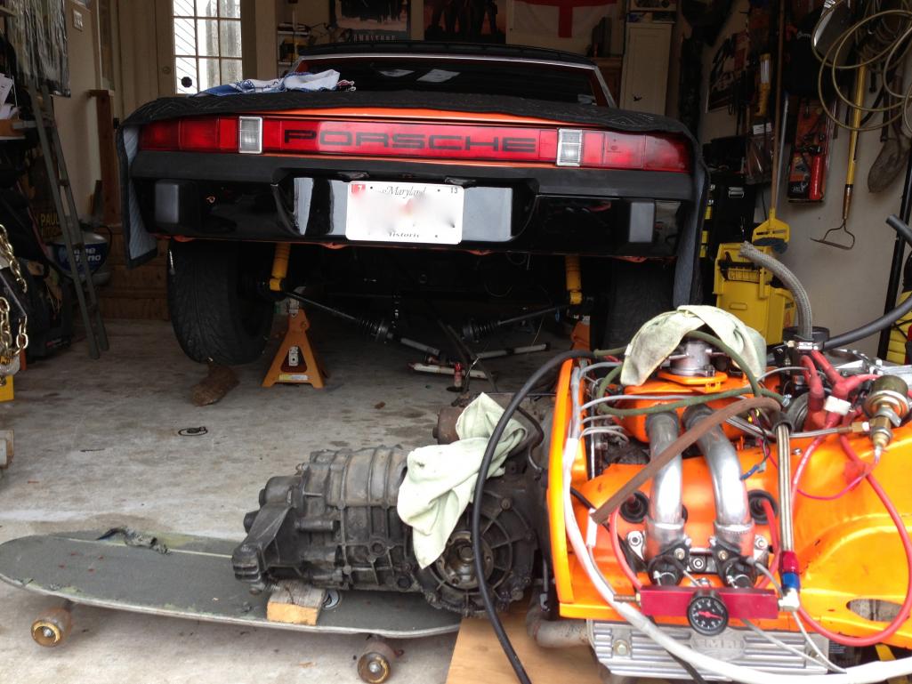
Posted by: ChristopherB Mar 31 2013, 06:29 PM
Here are some photos just to make this more interesting. I used a skateboard and a motorcycle lift to move the engine into place. I replace the skateboard with a jack to lift together. I might get a scissor lift if I have to drop the engine again.
fuel pump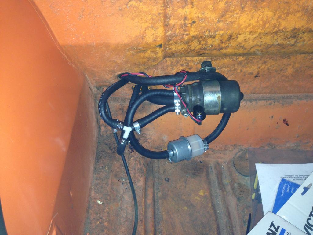
Posted by: ChristopherB Mar 31 2013, 06:30 PM
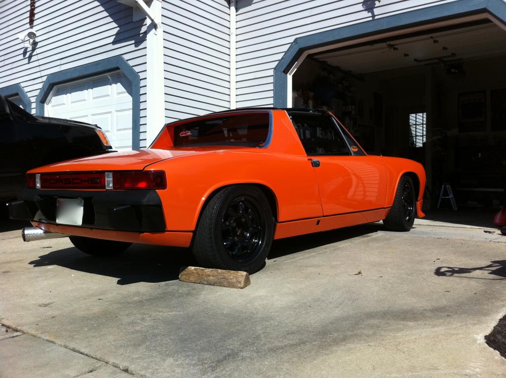
I did not even know what a valve cover was when I bought this car about 2 years ago.  The PO was a little worried about selling the car to me because he could tell I was totally clueless. I am really enjoying working on the car, but with the weather improving I am getting anxious to drive the car again. Here is a shot of the car.
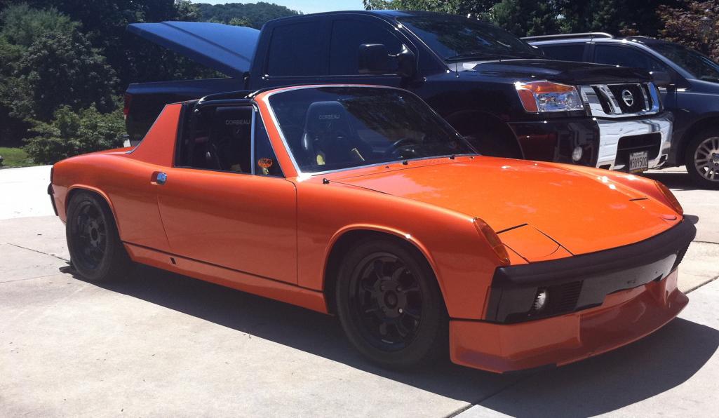
Posted by: ChristopherB Mar 31 2013, 06:40 PM
Posted by: type47 Mar 31 2013, 07:19 PM
Only 20 more days 'til Hershey. That should be enough to get the car fine tuned to join the madness ...
Posted by: ChristopherB Mar 31 2013, 07:48 PM
I have a question about raising the engine into place. I have it all the way forward so the mounts are lined up to raise the engine, but my fuel rails are hitting the pick ups for the trailing arms. Is this usually a tight squeeze with the fuel rails or am I missing something in the technique? Do I need to lift the engine to get the fuel rails higher than the pick ups and then push it back before finishing the lift?
Posted by: Dave_Darling Mar 31 2013, 09:22 PM
You should be able to just push the fuel rails around. They're only held onto the engine by the hoses to the injectors. Those should have enough flex that you can move them out of the way.
Or remove the rails, or the injectors to get them out of the way. Not hard to re-attach either once the engine is in the car.
--DD
Posted by: ChristopherB Apr 1 2013, 04:45 AM
You should be able to just push the fuel rails around. They're only held onto the engine by the hoses to the injectors. Those should have enough flex that you can move them out of the way.
Or remove the rails, or the injectors to get them out of the way. Not hard to re-attach either once the engine is in the car.
--DD
Great Thanks
Posted by: SUNAB914 Apr 1 2013, 08:12 AM
Just my .02 cents, in the pic of engine it looked like the THS (Temp head sensor) wasn't hooked up, I see you still have original FI but with a bunch of other stuff added. Others more familar might lend a helping hand. I don't think you could get it running right without the THS hooked up? Might be the whole issue, if I'm seeing it correctly.
Good luck
Posted by: ChristopherB Apr 1 2013, 03:06 PM
Just my .02 cents, in the pic of engine it looked like the THS (Temp head sensor) wasn't hooked up, I see you still have original FI but with a bunch of other stuff added. Others more familar might lend a helping hand. I don't think you could get it running right without the THS hooked up? Might be the whole issue, if I'm seeing it correctly.
Good luck
The THS is a small wire that comes through the tin between cylinders 3 & 4. you can see the long white plug for it on the new harness. You can't see the wire going to it however. It is there and plugged in. I know this because Jeff's diagram for the new harness is very good and easy to read. I appreciate your input, and I will need some more help in the next few days as I connect the decel valve and all the vac lines.
Thanks
Posted by: ChristopherB Apr 5 2013, 01:39 PM
I need some help learning where things go. I got the engine back in the car which has got me yearning to drive!
Where does the wire on the alternator harness that looks like a ground attach? The red one in my hand.
I have two black wires that come together and also look like a ground. I do not know what these are, nor do I know where they attach. They seem to come from the rear of the engine bay in the corner driver side. Please confirm that the brown, red, and green wires from the alt are attached to the relay board properly. They do not have a plug though Jeff sent me one with my new harness. I have no idea how it works, or how to get the terminals to clip into the plug.
I ended up pulling the injectors to install the engine, and I am glad I did as I had the lines too short coming from the rails. 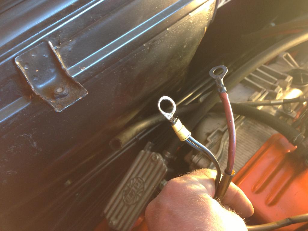
Posted by: Dave_Darling Apr 5 2013, 04:46 PM
The connector with the yellow insulator on it is not stock. The wires may or may not be. What colors are they? The lighting is making them look blue to me.
The red wire looks an awful lot like the power wire from the alternator. It should hook onto the same stud on the back of the starter that the main battery cable hooks onto. The battery won't charge with that not connected... (Don't ask how I know this.  )
)
Trace all of those wires to the other end to make sure you know where they come from. You can look at the wiring diagrams to see what hooks up to the part at the end.
Your Haynes manual should have a B&W diagram of the relay board with the three alternator control wires labeled for color. Or you can look on the Pelican website for a color version.
The black plastic plug is pretty easy to deal with--you just push the metal contact into the back of the plug. Make sure that the little tab sticking up from the contact is on the same side of the slot in the plug as the notch in the slot. (Look at the front side of the plug, note that they are shaped like a flat letter "T". The tab sticking up fits into the leg of the T.)
--DD
Posted by: ChristopherB Apr 5 2013, 05:04 PM
Thanks,
First lesson learned this week is to take the time to label everything specifically!
So the brown, red, and green wires are on the relay correctly. Yes?
You are right the black wires are not stock but could be a ground for the hal effect sending unit, or the oxygen sensor, so I will just find a ground for that.
The red wire is the power from the alt so now I know where it goes.
Thanks again.
Posted by: Dave_Darling Apr 5 2013, 08:09 PM
"Could be a ground" could also be a hot wire. Hook it to ground and it could catch fire. FIRE BAD!! Figure out where it comes from before you hook it up, please!
Color wiring diagrams can be found here:
http://www.pelicanparts.com/914/914_electrical_diagrams.htm
They're the same as the ones in your Haynes manual (you have a Haynes manual, right?) but in color.
Relay board diagram:
http://www.pelicanparts.com/914/parts/Electrical/914_electric_73E.jpg
For those three wires in question, red goes to the forward connection, brown to the middle-left one, and green to the rear connection. Which matches what you have in that picture, so you should be fine.
--DD
Posted by: ChristopherB Apr 6 2013, 07:56 AM
Thanks Dave.
I do have the Haynes manual, but the link you provided in color was much better.
I talked to the PO yesterday and he said all of his grounds are in black. Looking at some old photos of the car he provided led me to find where he had it grounded. It went straight across the rear of engine bay and attached to the top bolt on the engine case in the center. It is just aft of the three ground connections on the FI harness.
Posted by: ChristopherB Apr 7 2013, 11:20 AM
Working on the car today and the throttle cable popped off the ball at the pedal cluster. I had just attached the cable to the throttle body and was testing it.
The cable is fine, and it slides freely in the tube. Do I just pop it back on the male socket and see how it works. Is there a tension or geometry issue that would cause this to happen?
Posted by: ChristopherB Apr 7 2013, 11:35 AM
I popped the cable back on the pedal. I think the throttle butterfly valve stuck and the force popped the cable. However, looking down into the plenum, I see some oil. Is this ok or should I clean it before resuming?
Posted by: ChristopherB Apr 7 2013, 12:04 PM
Posted by: ChristopherB Apr 9 2013, 02:36 PM
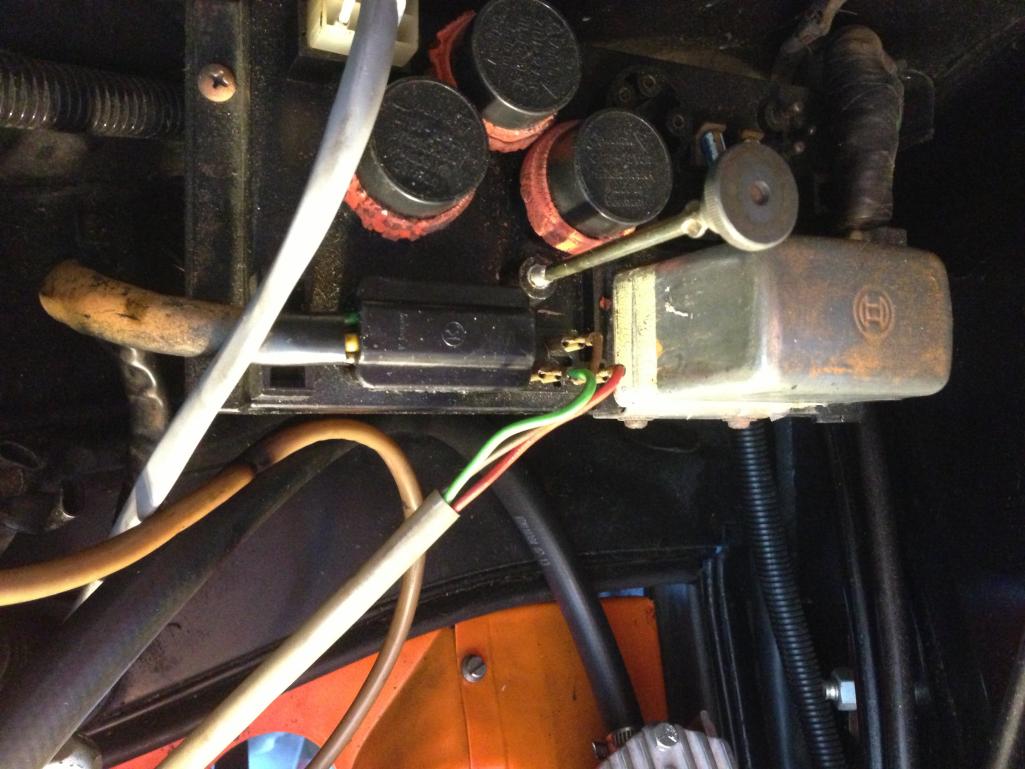
I am ready to connect the ignition. I have a dizzy along with a crane ignition set up. I am wondering about the connections My harness coming from the starter has two female slide connectors that mounted to the blue coil. The new set up is all wired, but it also has female slide connectors. Howe should I proceed? I am thinking I should replace the two females on the crane ignition with males, and that connects to the starter harness. Is it that simple?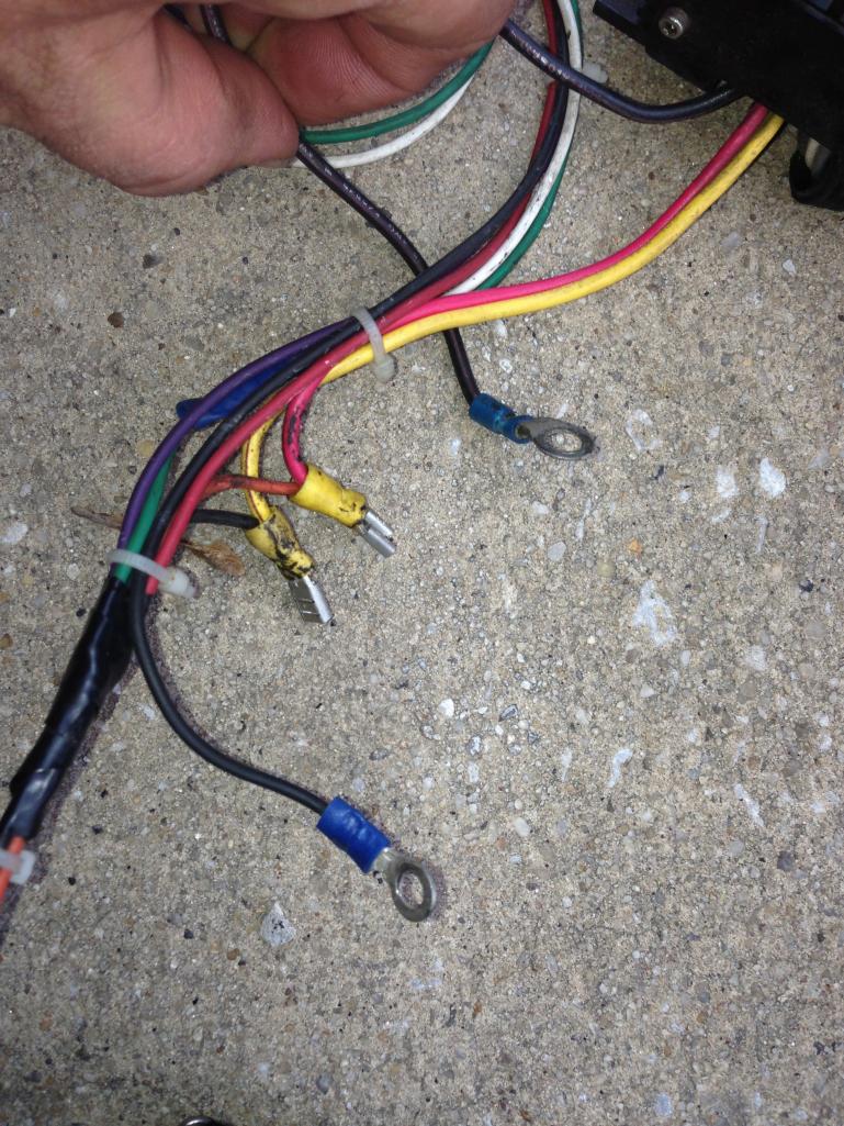
Posted by: ChristopherB Apr 9 2013, 02:37 PM
here are the two connectors on my car.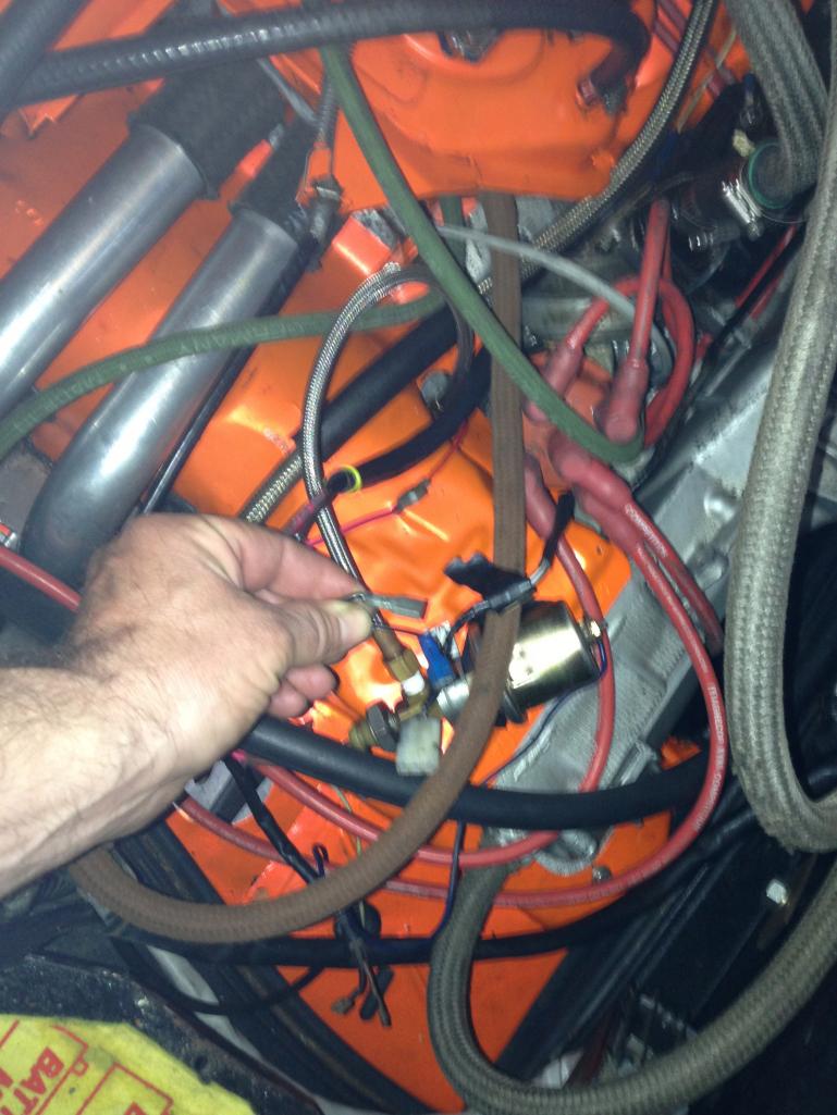
Posted by: ChristopherB Apr 9 2013, 02:41 PM
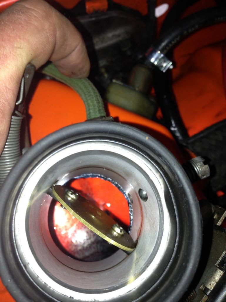
I also have these two connectors on my positive battery cable. One of them was wrapped and the other exposed. Are they used?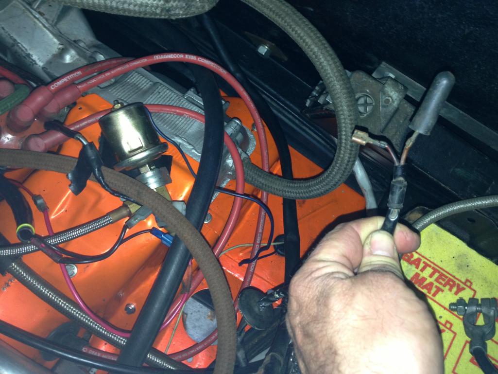
Posted by: 904svo Apr 9 2013, 03:58 PM
I also have these two connectors on my positive battery cable. One of them was wrapped and the other exposed. Are they used?
Blower fan motor?
Posted by: ChristopherB Apr 9 2013, 05:37 PM
Thanks. That could be it. Car doesn't have heat or AC.
Posted by: Dave_Darling Apr 9 2013, 06:10 PM
Those first wires are all aftermarket. Someone added them, or used them to make repairs. The colors aren't right, the connectors aren't right. You are going to have to trace them to see what's on the other end of the wires. Try to match up that connection with a wiring diagram to see where this end should plug in.
Though if it's related to aftermarket ignition stuff, it won't be in the factory diagrams either...
The heater blower wires should be on the driver's side of the engine compartment, not the passenger's side.
Those wires could be factory. One looks brown, I'm not sure of the color of the other one. It looks kind of like a black wire with a red stripe, which would be the power wire to the coil.
--DD
Posted by: dpires914 Apr 9 2013, 07:14 PM
Nice car. What color is that? Nepal orange, Signal orange or Phoenix Red?
I did not even know what a valve cover was when I bought this car about 2 years ago.
The PO was a little worried about selling the car to me because he could tell I was totally clueless. I am really enjoying working on the car, but with the weather improving I am getting anxious to drive the car again. Here is a shot of the car.Posted by: ChristopherB Apr 11 2013, 03:47 PM
Thanks Dave and dpires,
I don't know the color because while it was originally orange, it was not repainted exactly the same orange.
I have everything connected to the car but the axles. I had to deal with a few fuel leaks but that was simple and I have 29 psi at the fuel rail. Happy about this because, I moved the fuel pump to the front trunk and replaced all the hoses and clamps. At least that was successful.
I just have to go over the setting up of the dizzy and timing.
I am going to have to leave it for a week to go to DisneyWorld with my family, but will post my progress when I get back.
Powered by Invision Power Board (http://www.invisionboard.com)
© Invision Power Services (http://www.invisionpower.com)