Printable Version of Topic
Click here to view this topic in its original format
914World.com _ 914World Garage _ MPS
Posted by: 76-914 Jul 17 2012, 10:26 PM
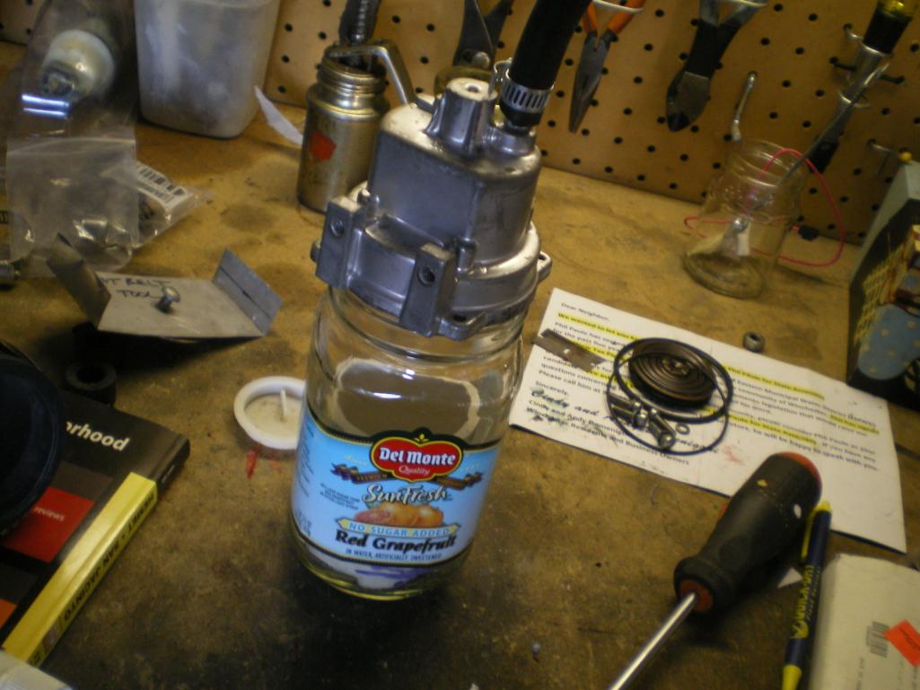
Awhile back Lew Mengle gave me a beautiful looking MPS which he thought was rebuilt. I ohmed it out (I did this first in hopes that if it passed this test it would have a much better chance of passing the next test) and it tested OK. Next I checked to see if it would hold vacuum. Failed. Miserably at that. Couldn't get it to go beyond 5 no matter how fast I pumped that vacuum pump. So I tucked it away.
Last week I ordered 2 of the unobtanium diaphragms (that Chris @ Tangerine Racing is offering) so I thought I should get a head start on replacing one using my spare MPS.
I don't mind telling you that I've always felt intimidated by these things so I'm looking forward to this about as much as fighting the school bully. My goal is to open this up without destroying it, clean it up and hopefully understand how to install the new diapragm and then return it to a setting that is very close to original. At that point I would hand it over to someone else to set to spec's with the proper equipment.
I'm a little suspect of this particular unit as it appears someone's tinkered with the numbers. More to come in the following few days.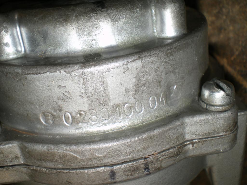
Posted by: SLITS Jul 18 2012, 07:09 AM
That unit has been "rebuilt" at least once in it's life as screws are not stock .. rivets are.
Getting the unit one to seal is the real problem when replacing the parts. I have torn apart about 5 of them attempting to replace the diaphragm. Then there is the seal around the electrical connector .... oh well.
Some "rebuilders" will grind off the numbers, some don't.
Posted by: benalishhero Jul 18 2012, 09:17 AM
![popcorn[1].gif](style_emoticons/default/popcorn[1].gif)
Posted by: 76-914 Jul 18 2012, 07:51 PM
Again, I want to point out that any of this info is available at Brad Lander's site. I've read over his site, in it's entirety, several times yet I always find something new when I go back. Here is the unit with the epoxy removed as well as the stop screw. As I just mentioned, I want to return this to it's original state as close as I can, mechanically. So I marked the screw's slot position on the end w/ a Marks-a-lot. It was 9.75 turns or 9.75mm into the body, in that the thread pitch = 1.0. You gotta love that metric system, huh? I don't think I could figure that out in inch's. Inside is the set screw and nut where some of the adjustments are done. The other adjustment is that screw cap under the epoxy.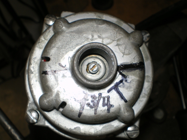
Next, in my case, is to remove the four screws holding the halves together. And behold, the Great and Powerful Oz. Shit, I'm a little disappointed. I was expecting some trumpets to go off, or something. I can now confirm what Ron just mentioned. I just hope he doesn't tell you the end.  I didn't know about the rivet/screw detail but I did read where Brad said repair shops often add an o-ring to supplement the existing NLA washer (we should tell Mikey914 about this). And this unit has both seals, so there you are. The o-ring is on the half to the left.
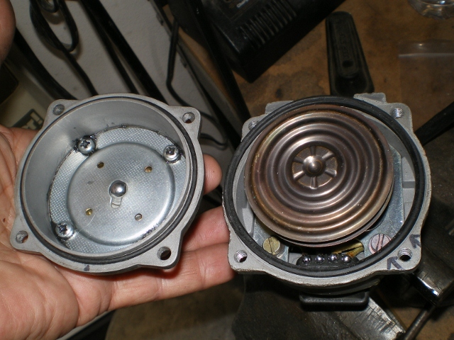
This pic is the same shot except I have lifted and am holding the aneroid cell (is that right? I really don't know shit from apple butter about one of these things.) This is the mechanical device that reacts to vacuum changes, which in turn moves another device which converts it to an electrical signal and yadi, yadi, Go read about it at Brad's site; again damn it  .
. 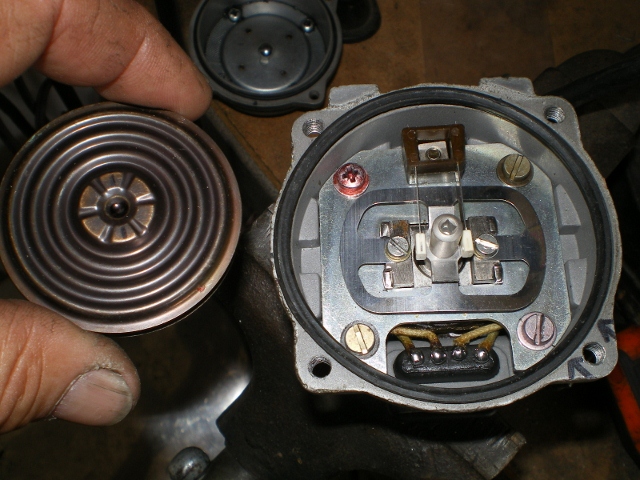
I've gotta say this cell looks to be in excellent shape but who knows? I'll need to pull a vacuum on it to see if it holds. The 3rd pic shows it has markings because I wasn't sure if there is an up/down when I disassembled it.. 
As far as I can tell, if this half were to leak it would have to be where this electrical plug penetrates the body; where the body has been compromised in some fashion i.e. cracked or split or uneven sealing surface; or where it mates to the other half.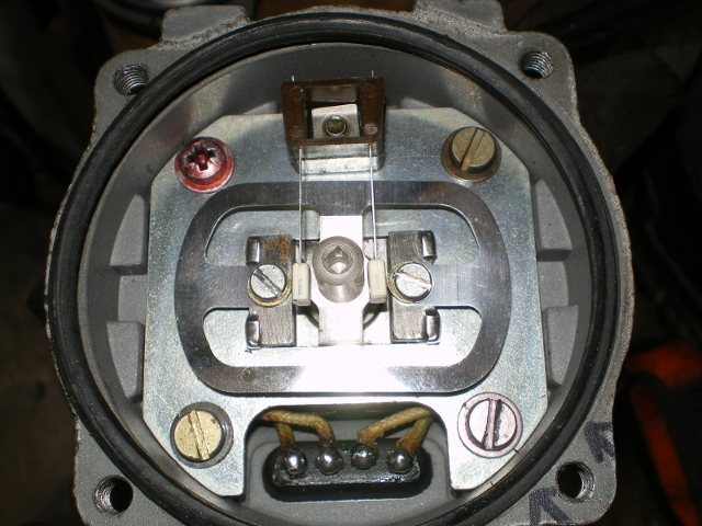
I'm trying to approach this from a common sense angle so I think I need to test case half's so I know which path to follow. I believe this half should be the easiest to test so I'll start here. After scurrying about I found this jar which mated the the OEM seal on the case half, perfectly. I pulled 15" vac and let it set for 15 min's. Whew, it passed and I'm glad because this side looks complicated. 
Next, I need to test the other half (the one with 3 openings on the end, hmmm) to determine if the diaphragm (that's the part Chris sells) is good/bad and whether the aneroid cell will hold, or not. More tomorrow. 
Posted by: benalishhero Jul 18 2012, 08:22 PM
Posted by: 396 Jul 18 2012, 08:27 PM
Sub...thanks!
Posted by: 914_teener Jul 18 2012, 09:59 PM
You don't show the diaphragm?  It goes in front of the aneroid cell.
Posted by: Bleyseng Jul 19 2012, 03:27 AM
where is the money shot? Open the cover!
Posted by: RobW Jul 19 2012, 06:23 AM

Posted by: SLITS Jul 19 2012, 09:51 AM

The left hand piece is what you have to worry about. The Barometric / Aneroid cells generally are not bad. It is good the right hand piece holds vacuum.
Under the 4 screws is the diaphragm that cracks and won't hold vacuum.
Good luck!
Posted by: Bleyseng Jul 19 2012, 09:55 AM
note the double O rings to seal the cover to the body. I never do that as it seems to leak in time.
Posted by: 76-914 Jul 19 2012, 07:46 PM
OK, I'll cross my fingers and "hope" it is good. But let me draaaaaaaaaaaaaaaag this out a bit more. Before I jump to the "suspect" half I want to see if this cell will hold vacuum so I measured the cell first.
[attachmentid=323655]
Then I sat it upon an upside down ceramic cup inside of a "Food Saver" vacuum canister  . and pulled enough vacuum to make it expand maybe 1mm.
Before: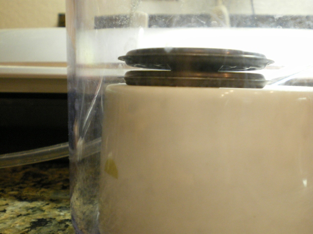
After: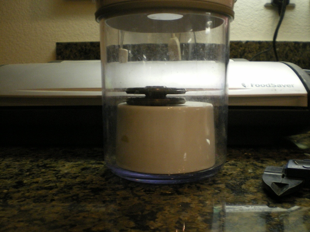
After it held for 15 min's I removed it and measured it to see if I had stretched it. Nope.
[attachmentid=323656]
Next, I began to fret about whether the cell would react to altitude changes properly and how do I check that. Would the upper limit be 12,000' ASL yadi, yadi....I then referred back to Brads site and there it was He had already done the homework and the numbers were there for 5"/10"/15"vac. This is turning out easier than I thought.  Armed with these numbers, my Food Saver Canister and my mighty vac I was able to nominally duplicate Brad's results as seen below.
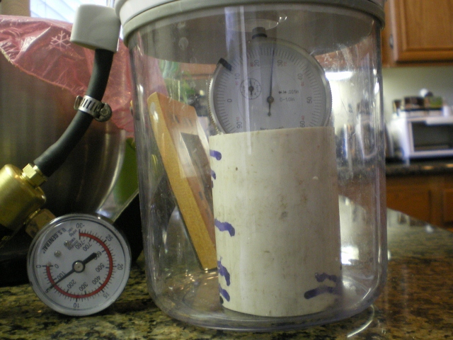
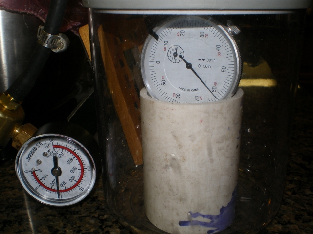
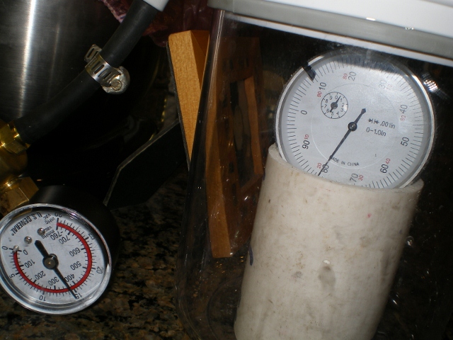
I'll take you for a tour thru my "Skunk Works" but you must never reveal any of my BS skills. This is a short piece of 2" PVC and centered quite nicely on the bottom is the cell. The dial indicator tip sits neatly atop the indented center of the aneroid cell. It was then just a matter of zeroing it out and drawing the vacuum.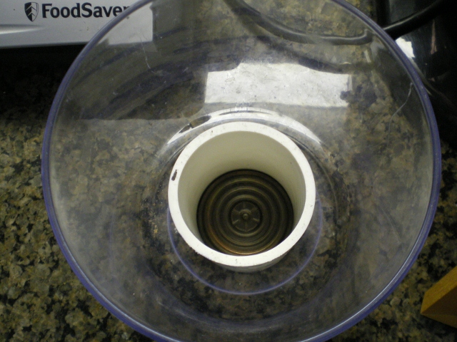
As you can see my overall movement was .080 or 2.032mm which is damn close to Brad's results so I'm good to go in this department. Now on to the other half. As you can see there is not much to it. Just 4 small screws or so I thought. That SoB was a trick. I didn't want to push it out with a dowel from the backside because I thought I might ruin something so I took an dental tool and snagged the edges of the screw holes and gently lifted as I cussed like a Drill Sgt. Eventually it lifted and revealed what Geoff so eloquently referred to as the Money shot. That is a gasket sitting in the housing. The silver plate that the 4 screws pass thru is under the diaphragm and isn't visible in this pic.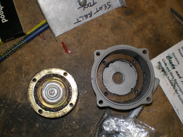
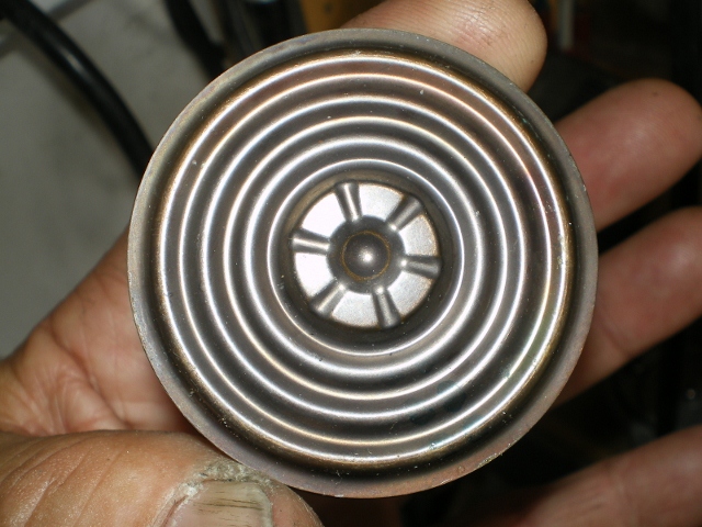
Here is a better shot of the diaphragm. I can't find any tears or rips. I poured alcohol on it and it held. Plus, it's clean as a whistle except for moly grease it was set in w/ thegasket. I'm glad that I didn't abuse this when removing. 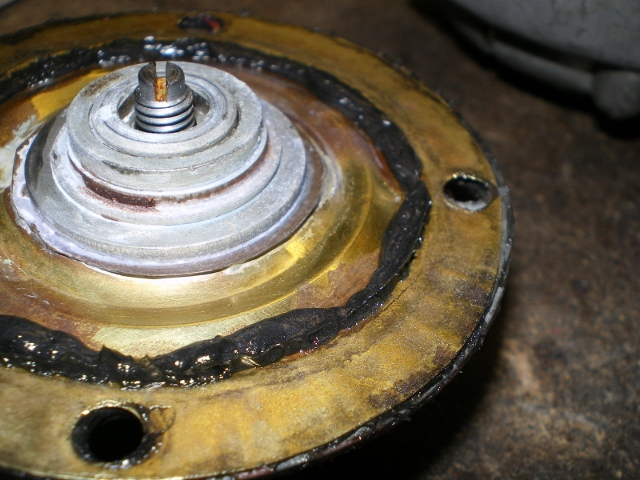
Here are the misc pieces cleaned and dreased for the Family Photo: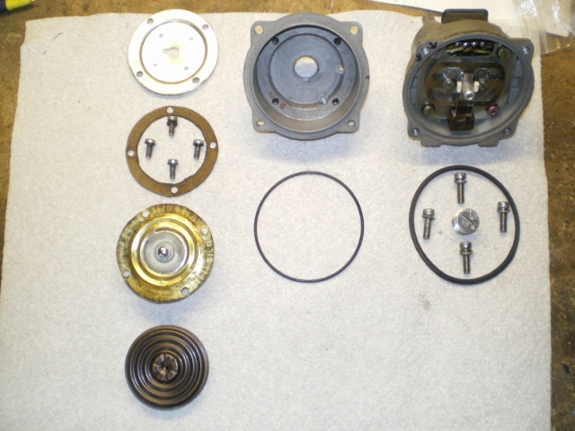
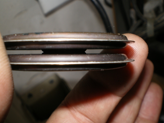
So it appears that the diaphragm is good yet there exists a leak on that side. You know what I think it is? This: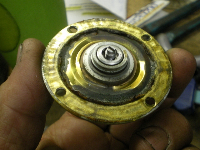
The edge is wavered. I think the the gasket is hardened and the grease/gasket combo just wasn't enough. I think I'll 86 the gasket and go back w/ some gasket goo in hopes that it can fill those voids.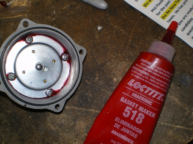
If I remove this gasket I'd better get a measurement so I can compensate for it.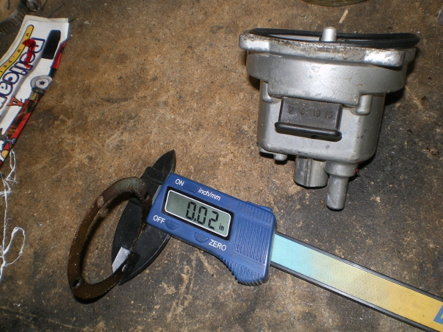
And while that sets up I've found just the thing to test my new seal. More on this, later.
Attached image(s)
Posted by: brant Jul 19 2012, 08:08 PM
that diaphram looks to be stamped from brass...
all of the stock ones I've taken apart looked much more like copper
so more confirmation that its been rebuilt
and the aftermarket restamps are not supposed to flex the same as the original copper/berrilium, so this one may not have the same characteristics as a stock one when you get it back together....
I would throw a wide band on it if you can borrow one when your done. Its amazing how sensative the adjustment screws are. I am sure you will be able to get it back exactly as you found it... but less sure that the rebuilder got it exactly to the correct settings.
brant
Posted by: Racer Chris Jul 19 2012, 08:34 PM
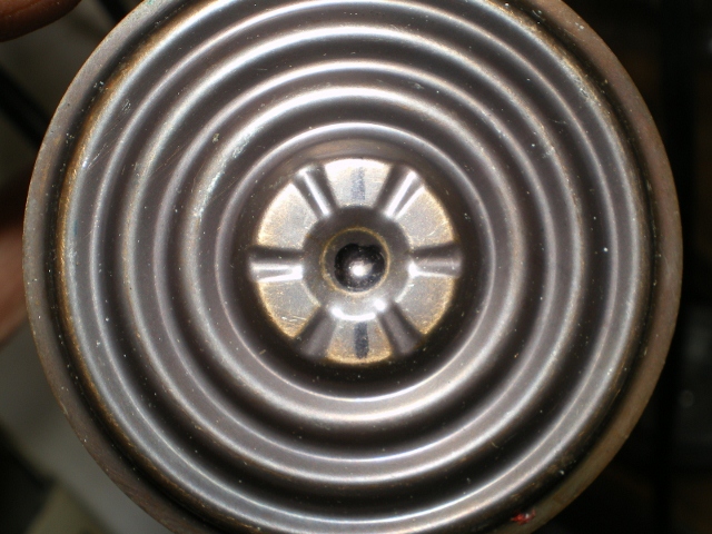
Sometimes cracks are invisible until the edge is flexed enough to make the crack separate.
Most cracks propagate where the inner edge of the reinforcing ring and the housing on the other side contact the diaphragm, about 3/8" from the edge.
That's where its under the most stress during operation.
That looks like an oem diaphragm, but an older design, and I think I see a crack in the first closeup picture.
Edit: However, it has different coloration, the ripples at the edge suggest less than perfect stamping, and it appears to have sealant around the hub.
Posted by: Bleyseng Jul 20 2012, 05:07 AM
That is not a OEM diaphragm or even a good rebuilt diaphragm. It looks to be soldered to the center piece so toss it in the "shitty parts bin" and wait for Chris's part. 
Posted by: 914_teener Jul 20 2012, 03:53 PM
That is not a OEM diaphragm or even a good rebuilt diaphragm. It looks to be soldered to the center piece so toss it in the "shitty parts bin" and wait for Chris's part.

Yes that is definitely not copper beryllium diaphram and is a rebuilt unit plus....
Man...you are the man.....your wife lets you work on teener parts in the kitchen?...
Posted by: FourBlades Jul 20 2012, 04:29 PM
This is an excellent thread, nice investigative work man! 

John
Posted by: 76-914 Jul 20 2012, 11:43 PM
Don't get caught up in the type of diaphragm. As I stated in the beginning, this is merely an exercise to prep me for the arrival of the parts I've ordered from Chris. I reuse that diaphragm as you will see in these pics because I'm chasing a leak and I want to see where they leak besides the obvious break or tear. BTW Geoff, that is solder and Chris, that isn't sealant but some grease that was used in conjunction with the gasket. Is that normal? Anyway, This is a look at what I used to make this tool. It's a 2" CI to PVC rubber coupling, an 1.5" PVC coupling, an 1.5" x 1/2" PVC bushing, 6" of 1/2" pipe and one 1/2" 90.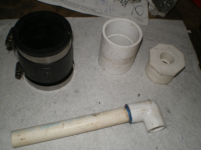
And when attached (I didn't glue anything so I could use it later he,he) you could see the conglomeration and the MPS body half in it. It was tight but it fit. The other end was large but tightened down nicely over the coupling. Do what you will here but I turned my compressor down to 1psi at the tip. Next I placed a 3/8" x 7/8" cone washer with a brass ring for reinforcement.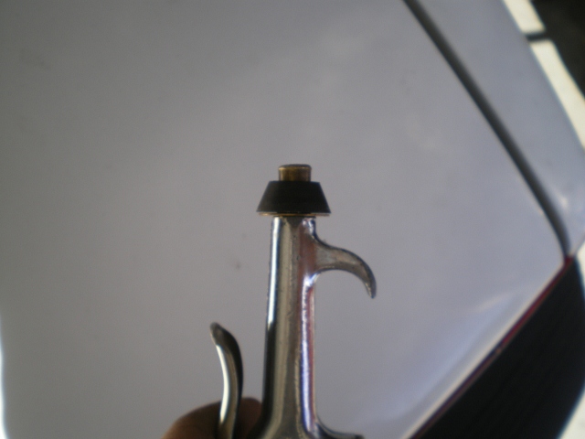
The green stuff in the bottle is dish soap and filtered water. A small amount of this was poured around the edge of the flange and apply a small amount of air. The water cooler is just a 3rd hand, if you will.
Well  . Those bubbles don't look good so it's back to the drawing board. I think the "gasket maker" sealant was mis-used here. I should mention that I saved the NLA gasket and made one from the phone book cover. I installed it in the same order (MPS body, gasket, diaphragm then cover plate) but I believe that wavey assed diaphragm will need a gasket on both sides. And I'm going back with grease in hopes that the next gaskets will absorb it and swell a bit. Be back tomorrow. It's late.
Attached image(s)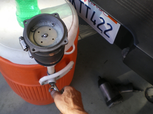
Posted by: Racer Chris Jul 22 2012, 03:47 PM
...
BTW Geoff, that is solder and Chris, that isn't sealant but some grease that was used in conjunction with the gasket. Is that normal?
...
Factory assembled MPS diaphragms were installed dry, with just one paper gasket on the cover side, AFAIK.
With that rippled edge on your diaphragm, I think RTV would have been better than grease.
Posted by: Bleyseng Jul 23 2012, 04:06 AM
I have seen 3-4 off those rebuilts with grease used as a sealant. WFT.
Posted by: 76-914 Jul 23 2012, 11:26 AM
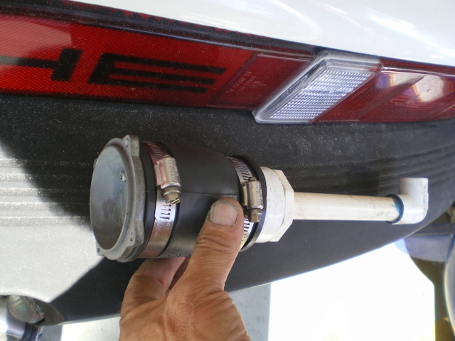
Well, I tried the grease and two gaskets with good results but not acceptable, either. Leak down from 15"vac to 0" was a little over 2 min's duration. So. I stripped it down again and went back with contact cement with identical results.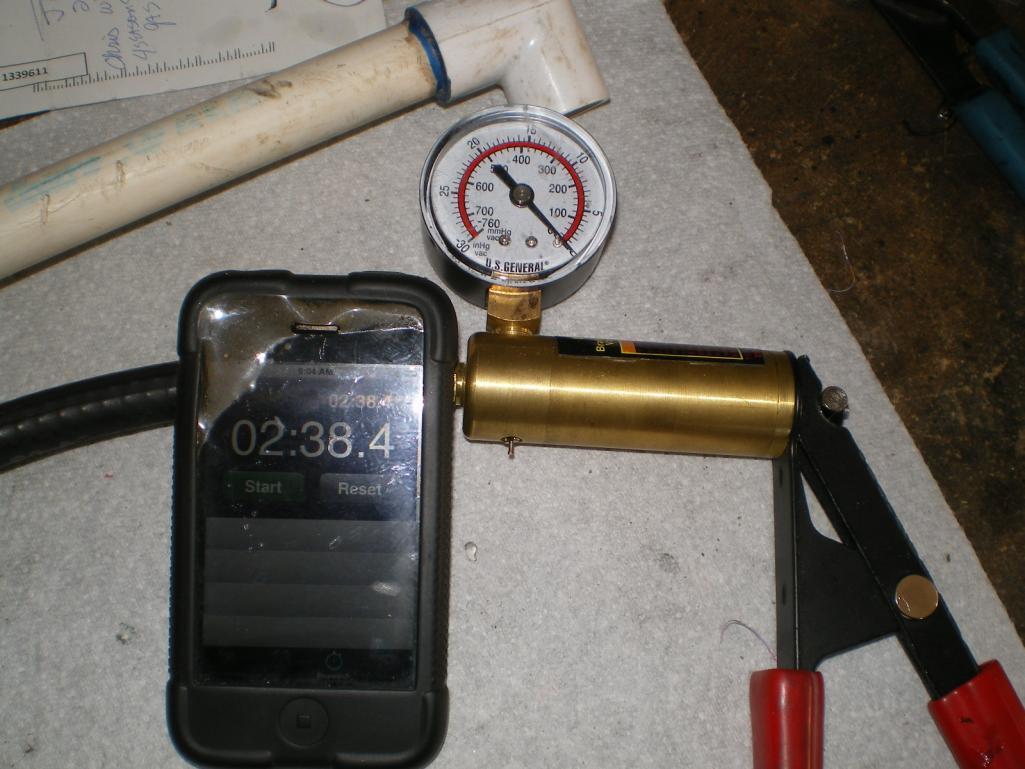
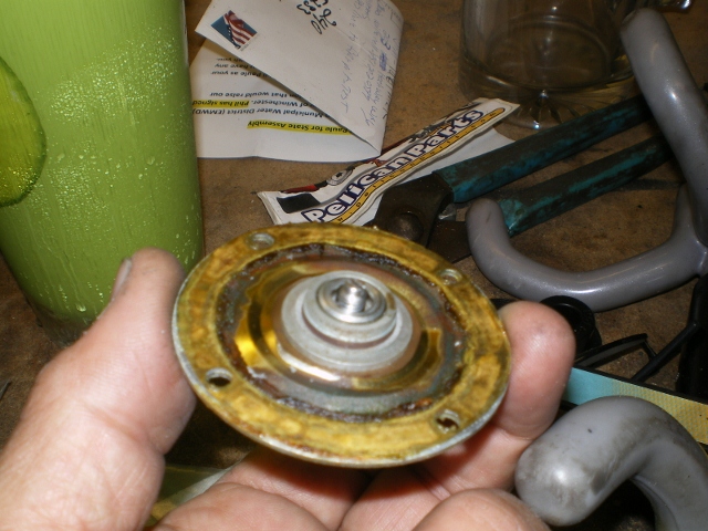
As seen in this pic, the leak around the outer seal was cured, whether using the grease or the contact cement method.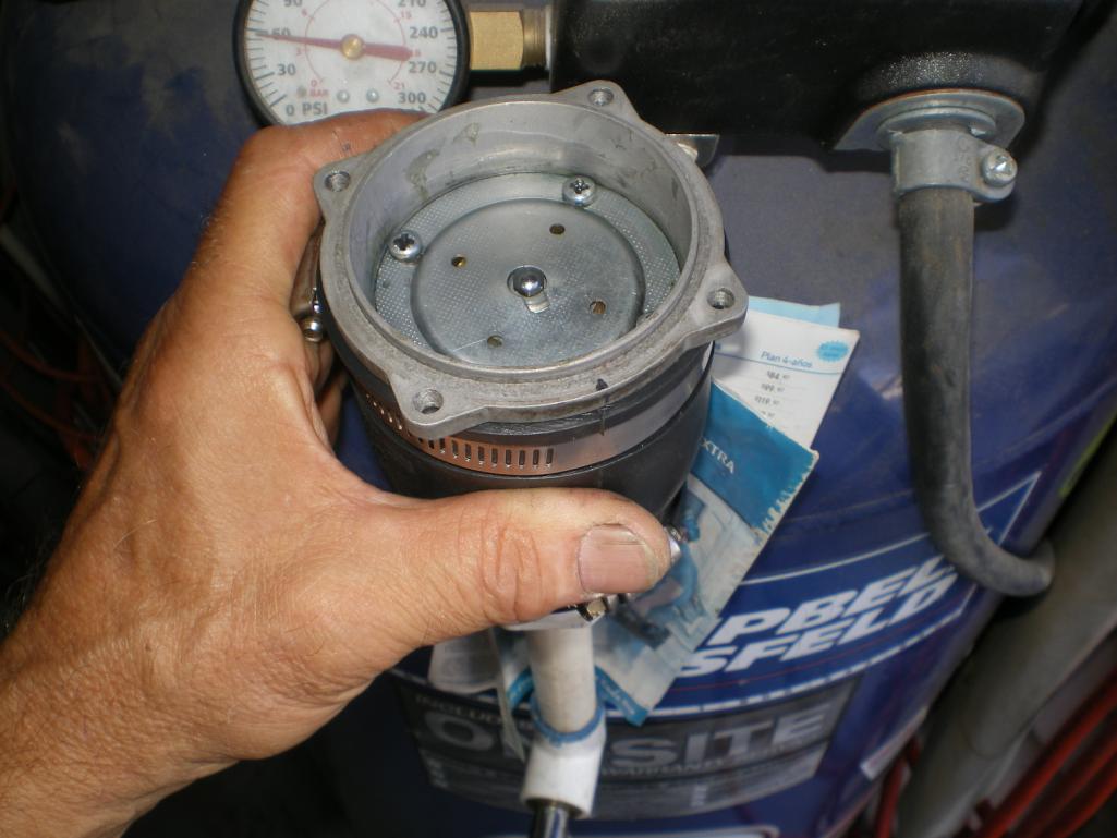
Normally I would not assume but since I am not using this diaphragm I shall. In that the diaphragm ceased to leak around the outer seals and no other leaks were discovered, I'm assuming that "this particular" adjustment screw has allowed a small amount of leakage. I decided to put it in the car for S&G's. I wished that I had had some adjustment tools to tinker but I didn't. When at idle it was hunting (too lean?? TB & ECU adjustments had little or no effect). It appeared (and remember that this source is completely unqualified) to stumble thru 3500 rpm occasionally, which might be related to the flex of the brass plate. It started and ran so I would keep this as an emergency back up unit but I would not consider using it unless adjusted to spec.
In summary, I will say that I am no longer intimidated by these "black boxes" and that I feel comfortable with installing one of these diaphragms, should they become available from Tangerine Racing. I believe that myself as well as any other member can easily replace this diaphragm in < 2 hr's, first attempt. I can probably do one in <15 min's, now.
EDIT: A quick and shameless plug; Geoff (Bleyseng) adjusted my last one to spec's and I would use him again.
Posted by: Racer Chris Jul 23 2012, 11:34 AM
FYI 1psi equals almost 28" H2O.
Posted by: 76-914 Jul 23 2012, 04:09 PM
FYI 1psi equals almost 28" H2O.
That's the gage on the comp that's reading 60psi. Test was only 1psi. I have a manometer for anything below that. Water never lies.
Posted by: SLITS Jul 23 2012, 04:13 PM
FYI 1psi equals almost 28" H2O.
That's the gage on the comp that's reading 60psi. Test was only 1psi. I have a manometer for anything below that. Water never lies.
Yeh, but fish fornicate in it!!
Posted by: Bleyseng Jul 23 2012, 06:27 PM
I have tried to run MPS with steel or brass diaphragms and they just don't give you the right response. The engine has no life or stumbles thru transitions but it will run.
Looks like you are having fun with this! nice job.
Posted by: ape914 Jul 23 2012, 06:36 PM
I have tried to run MPS with steel or brass diaphragms and they just don't give you the right response. The engine has no life or stumbles thru transitions but it will run.
Looks like you are having fun with this! nice job.
It is probably not so much a materials issue such as brass, vs. steel vs. copper vs..... as it is a design issue for the material selected. The properties of the stock diaphram could be replicated pretty well in any of these materials, with the correct convolution shapes, heat treatment, alloy content, and thickness of the material. The trick I think, would be in predicting the right design without a lot of trial and error.
Posted by: Racer Chris Jul 24 2012, 06:32 AM
It is probably not so much a materials issue such as brass, vs. steel vs. copper vs..... as it is a design issue for the material selected.
I think it is very much a materials issue.
The mechanical properties of beryllium copper make it uniquely suited for these diaphragms.
I'm sure its possible to create an assembly which approximates the output patterns of the inductive circuitry using a different diaphragm material.
However either the diaphragm would fail prematurely due to embrittlement, or the output signal would change over time due to creep of the material.
Posted by: ape914 Jul 24 2012, 10:05 AM
It is probably not so much a materials issue such as brass, vs. steel vs. copper vs..... as it is a design issue for the material selected.
I'm sure its possible to create an assembly which approximates the output patterns of the inductive circuitry using a different diaphragm material.
that is all I refered to, the response of the diaphram, not fatique life. Other materials can be used to replicate the response of a stock one. However fatigue life may not be good enough. by correct design, the fatigue life can be extended by minimizing the strain, which could be done with a different convultion pattern.
the best bet would be to exactly copy the original design, materials and shape.
Posted by: r_towle Jul 24 2012, 12:42 PM
Has anyone considered the transition step where the diaphram always gets torn?
Seems a dremel to round over that edge and take the sharpness out of that transition may prolong the life of the diaphram ??
Yes? no?
Rich
Posted by: Bleyseng Jul 24 2012, 02:13 PM
I think that all the stress is on that outer edge of the diaphragm no matter what you do or relieve. That is where the most movement occurs from what I can tell. The decel valve might helps reduce the slamming of the diaphragm under decel, lessening the hard pull of the vacuum. Under most driving conditions you are pull 4hgish in Partload, say at 35mph in 3rd gear. WOT or Ohg doesn't happen that much but everytime you are off the gas and are decelerating that engine pulls 15hg of vacuum.
Posted by: 914_teener Jul 24 2012, 07:06 PM
I think that all the stress is on that outer edge of the diaphragm no matter what you do or relieve. That is where the most movement occurs from what I can tell. The decel valve might helps reduce the slamming of the diaphragm under decel, lessening the hard pull of the vacuum. Under most driving conditions you are pull 4hgish in Partload, say at 35mph in 3rd gear. WOT or Ohg doesn't happen that much but everytime you are off the gas and are decelerating that engine pulls 15hg of vacuum.
Gonna send Chris Foley some bucks....as long as it is based on the original design.
Powered by Invision Power Board (http://www.invisionboard.com)
© Invision Power Services (http://www.invisionpower.com)