Printable Version of Topic
Click here to view this topic in its original format
914World.com _ 914World Garage _ Doug's A/C System
Posted by: dlee6204 Aug 22 2012, 08:05 PM
I thought I would document my A/C adventure in the hopes that it would be a good reference for anyone else considering A/C. I’ll first touch base on the stock system and on custom options and then start building my own system to start testing on. I’ve working on a few systems before but I'm sure there is someone that knows more than me so don't be shy sharing or adding anything. 
To begin things off here is one of the better overviews of an A/C system. Follow the link and you can see a breakdown of the whole system. 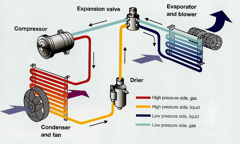
http://www.movacs.com/How%20it%20works/index.html
Anytime I refer to the stock system I will be referring to the dealer installed VPC system mostly because the only A/C cars I had came with this system and I have plenty of parts around.
I also borrowed some photos off this site so if I used any of yours... Thanks.
Compressor:
The compressor that came on dealer installed A/C systems was a York Piston style compressor that had a capacity of 6 cubic inches/Rev. From what I could find it used about 7-10 horsepower from the engine. You can still use this compressor however there are better, more efficient options out there. When choosing a new compressor it is a good idea to find one with a similar capacity. In this case going bigger does not mean better. An A/C system works as a whole unit and if you dramatically change one aspect of it, you will likely see negatives effects elsewhere. Choosing a compressor that’s too big will overwork the system, yielding no little to no benefit, and create a not-as-efficient system. During my search I looked mostly at Sanden style compressors so that's what I'll be referring to in my build. Using a modern compressor like the Sanden will only use about 3-4 hp from the engine. I have heard quite a few people use the Sanden 508 compressor with good results. It has an approximate displacement of 8 cubic inches/rev, which IMO is slightly more than I'd like to make a jump to. I'm not saying it wouldn't work, it obviously works, however I think I will get slightly better results and pressures using the Sanden 507 (approx. 7 cubic inches/rev). The SD507 is also slightly smaller in size than the 508.
Here is a picture of the York Compressor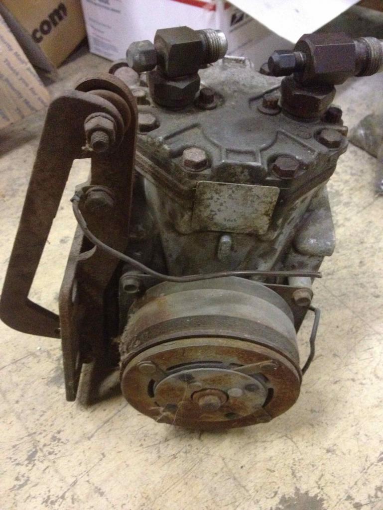
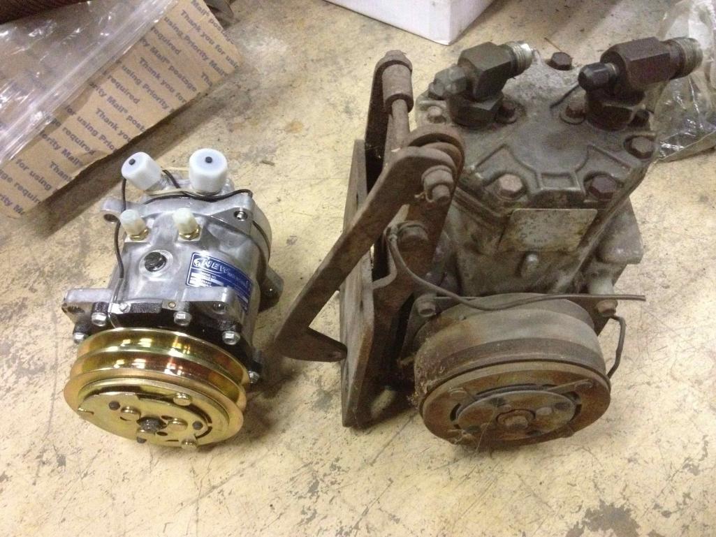
A side by side with the SD507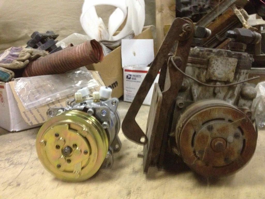
And here is a SD508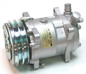
Posted by: dlee6204 Aug 22 2012, 08:05 PM
Compressor Mounting:
This is probably the biggest obstacle when deciding to go with A/C. The dealer installed the York compressor on the passenger side of the motor. In order for it to fit they had to cut both the engine shelf and the engine tin and in most cases, it looks like they did it with a hacksaw.... while blindfolded. The two disadvantages with this is that it no longer leaves the engine bay sealed and it’s also an ugly installation. The compressor was run via a belt and pulley that was installed behind the engine cooling fan. An idler pulley was also used. With the size of modern compressors, it leaves multiple potential locations to mount a new compressor.
Stock Location- There are many Sanden-to-York bracket adapters out there that would allow you to mount the new compressor in the stock location using the stock york mounting bracket. In some cases, depending on what compressor and adapter you use, you are able to install the compressor without cutting the engine shelf. The engine tin still needs to be cut though.
[If anyone has detailed pictures of a mounted York compressor, please share. ]
Here is the mount for the York.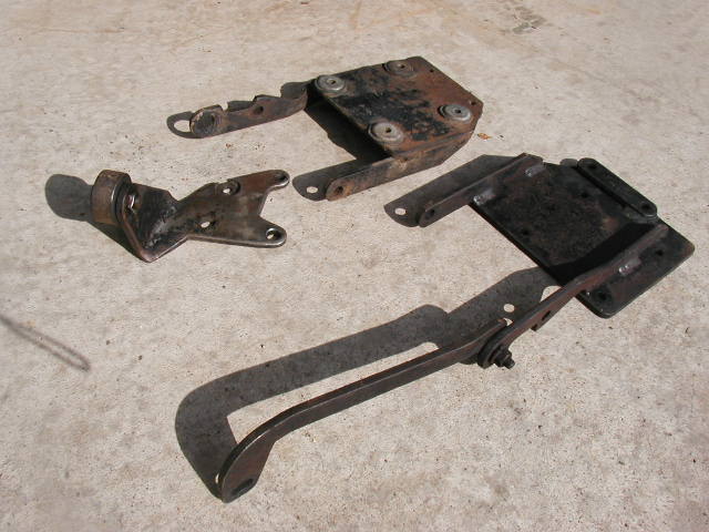
Here are some photos of SD508s mounted on the side.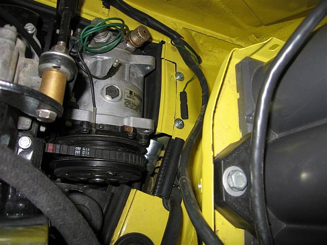
And a SD507 mounted on the side. 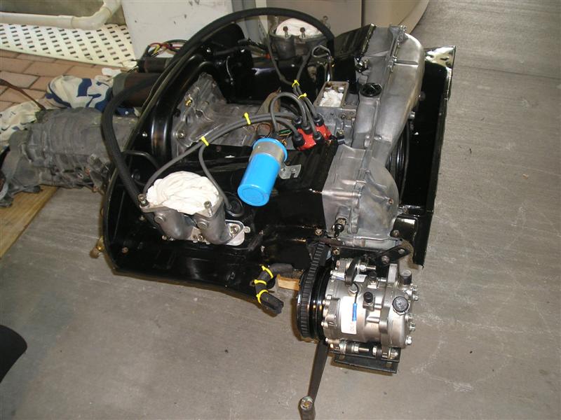
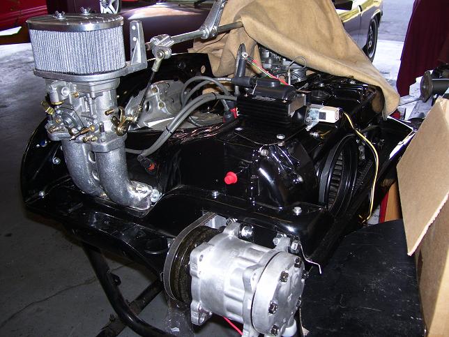
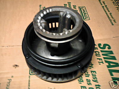
Top of the motor- Another place for installation is the top of the motor utilizing a pulley mounted to the front of the engine. In some rare cases I have seen the York compressor originally mounted on top of the engine which meant no need to cut the engine tin. IIRC 912's also did it this way too. Zambezi on this site is the only person I know who has successfully mounted a Sanden compressor on the top using a custom mount. He also used an offset pulley on the front of the fan to drive the compressor. Some pictures can be seen below. *If anyone is interested in an “offset” pulley, contact me. I’ve been working on something similar that would work. * I plan to mount my compressor on top using a smog pulley assembly to drive it. The smog pulley may or may not hold up to the abuse of driving a compressor… we shall see.
Here is a 912 setup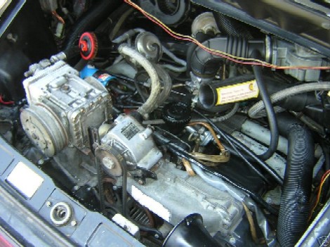
Zambezi's setup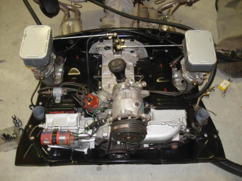
Under the motor- This is another option I have been playing with. I believe that one could mount the compressor on the passenger side of the motor UNDERNEATH the engine tin, similar location to that originally. I believe you would lose your heat on that side but it could still be done without cutting any tin.
Posted by: dlee6204 Aug 22 2012, 08:05 PM
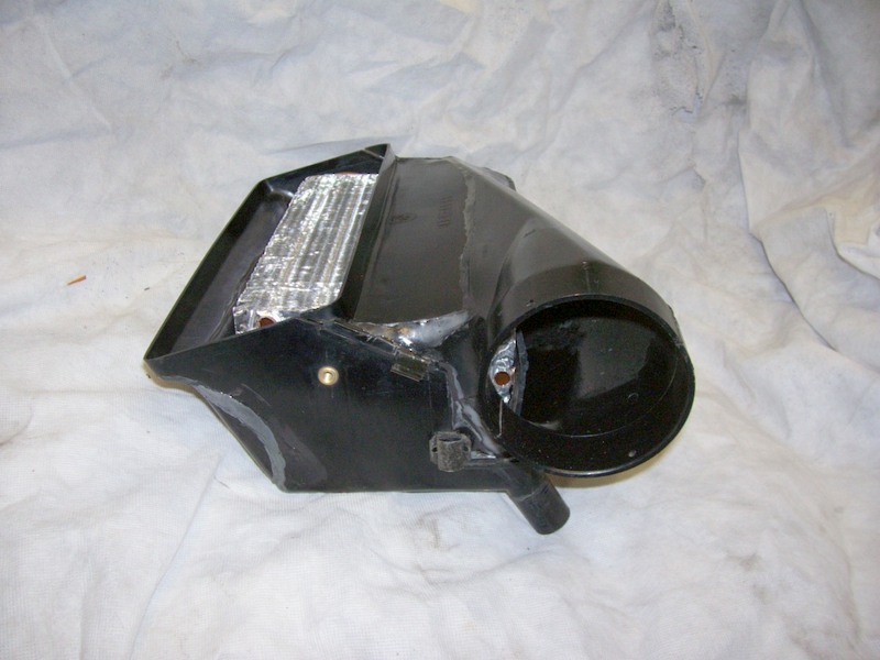
Condenser:
IMO this is where the biggest improvement can be made. Whichever option you go with make sure you get plenty of air movement across the condenser. The way I see it there are three options with mounting the condenser....
-Cut a hole in the front for the original condenser box. If doing this you might consider replacing the old tube&Fin condenser with modern parallel flow condenser. Parallel flow condensers are about 25-35% more efficient than the old style. So a modern condenser would compensate for the inefficiency of using r134. (R134 requires about 30% more condensing area that R12). So in theory it would give you just as cold temperatures for the same size condenser... in theory. I have to be honest though… I think the original condenser will be sufficient for enough for cool temps. It won't take much to cool the cockpit of the 914. Its something I’ll be testing out. The original squirrel cage fan also leaves something to be desired so you might consider upgrading your fan.
Original Condenser Box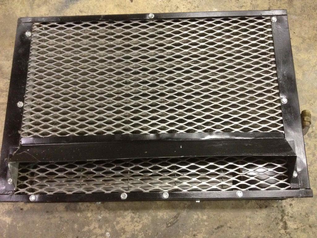
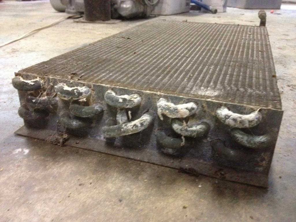
Tube&Fin Condenser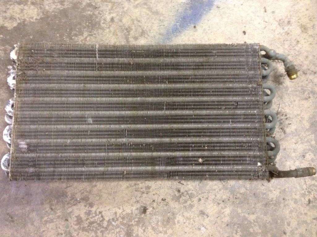
Helpful diagram showing different condensers.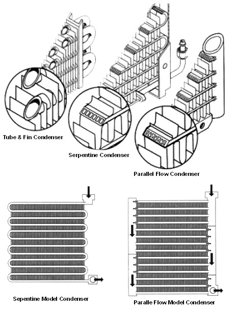
-Install a condenser on the engine lid. If I were to do this I would install a parallel flow condenser with fans and let that be it. The biggest downside to this is introducing even hotter air into the engine bay. Clay Perrine has a similar setup and he said that he hasn't had any issues so that shows that it could be possible. Another thing to note about this setup is that the engine bay is going to get crowded specially if someone has a top-mounted compressor with stock EFI. The top-mounted compressor might even interfere with the condenser. You will also need to mount the receiver drier in the vicinity as well.
-Install one in a fender-well. I have heard that some 911's had a condenser in the fender. I haven't looked into this option very much because I think it would be the most difficult to pull off specially when you consider that lack of room under 914 fenders and how big a condenser you would need.
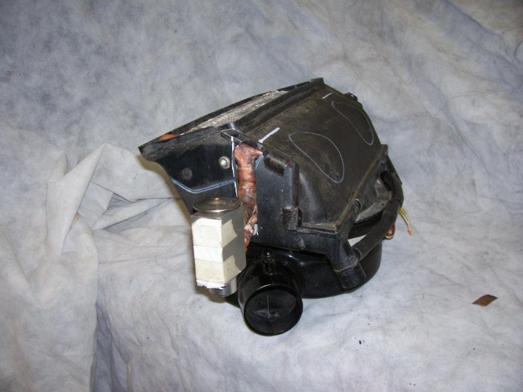
Evaporator:
There are ample aftermarket evaporator units out there. You simply have to find one that would fit, most however are going to be under-dash units. For my build I am going to use the stock VPC unit. IF using a used unit, make sure to replace the expansion valve. It is usually located at the inlet of the evaporator. If you have a water-cooled car, you might also consider a dual-purpose unit that handles both A/C and heat.
VPC Evap.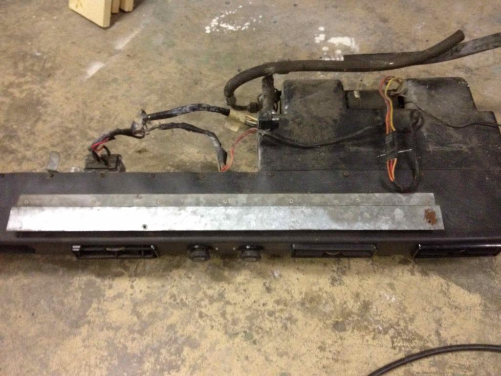
If an under-dash unit doesn’t strike your fancy, one of the best solutions but most difficult would be to install an evaporator unit in place of the fresh-air fan under the cowl. It would have to be a completely custom setup however you would still be able to use the stock heating system in conjunction with the dash air controls. This is something that I might consider later down the road.
Posted by: dlee6204 Aug 22 2012, 08:05 PM
Hoses:
Chances are that anyone doing an A/C system will need all new hoses. The old lines are compatible with R12 only. They allow the R12 to "breathe" and will not work if you are using R134. New Barrier hoses must be used if using R134. Your local A/C shop will probably be your best bet when getting new hoses made. If making your own hoses make sure to use the correct fittings (flare, o-ring, etc.).
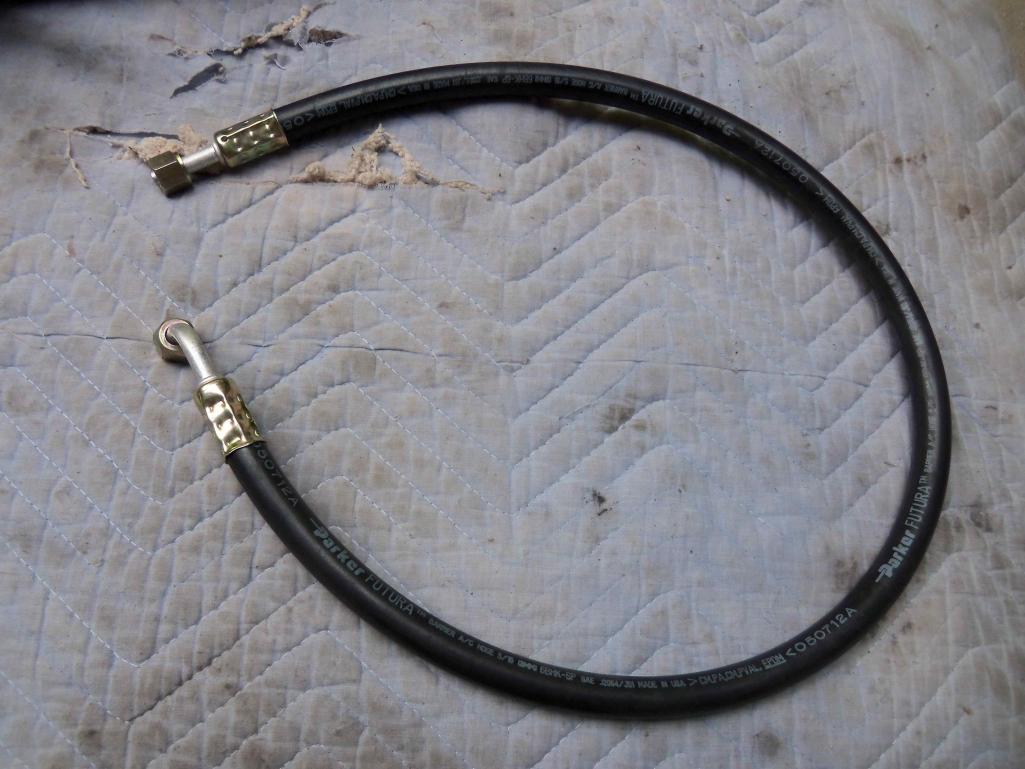
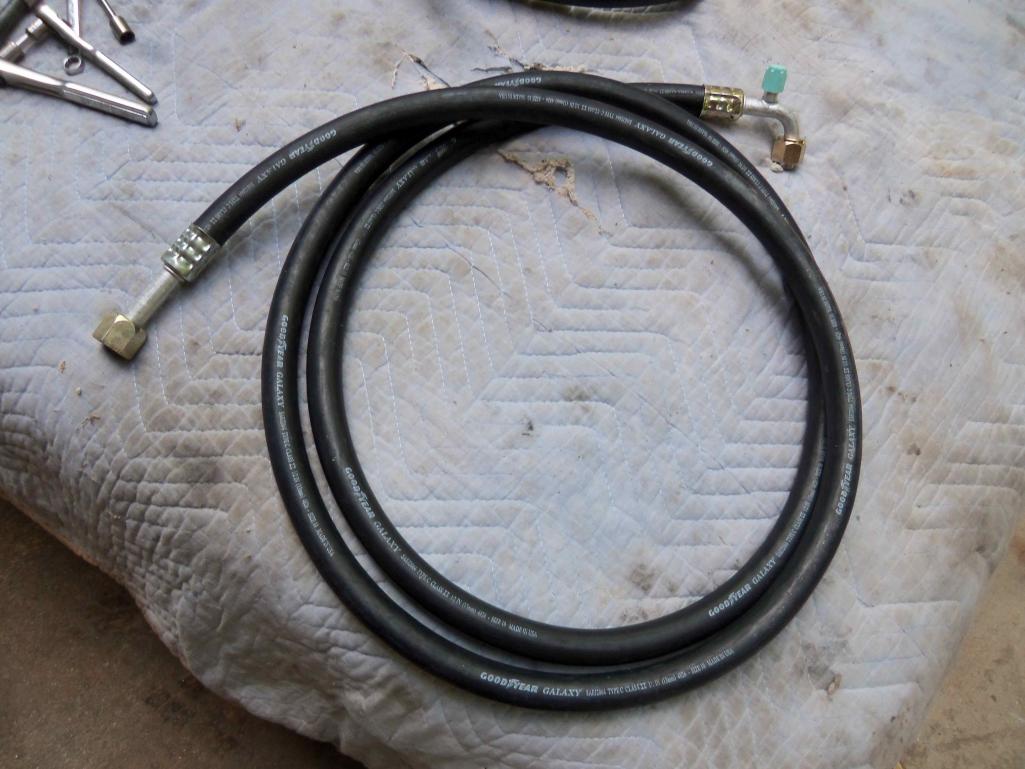
Some new charge port fittings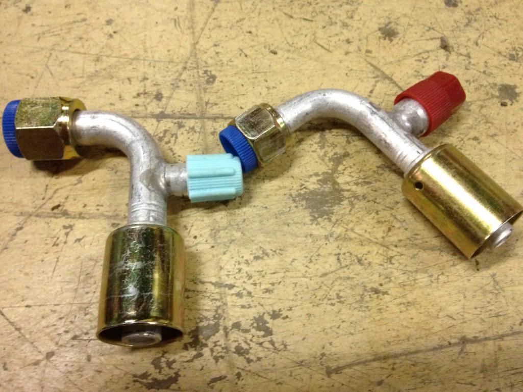
New Hose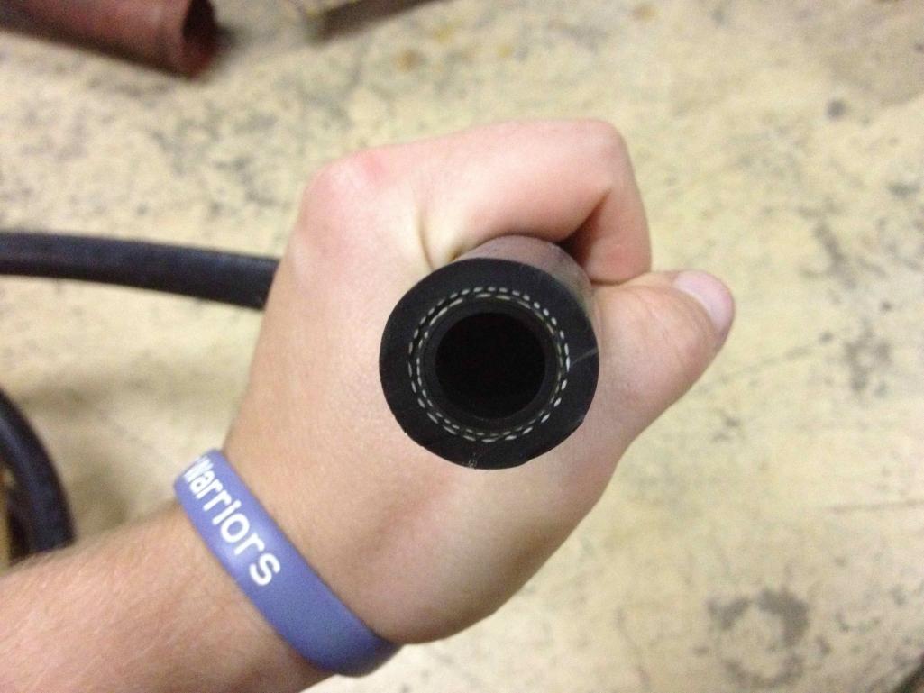
The SD507 was made for o-ring fittings so I acquired some o-ring to flare adapters. I ended up not using these.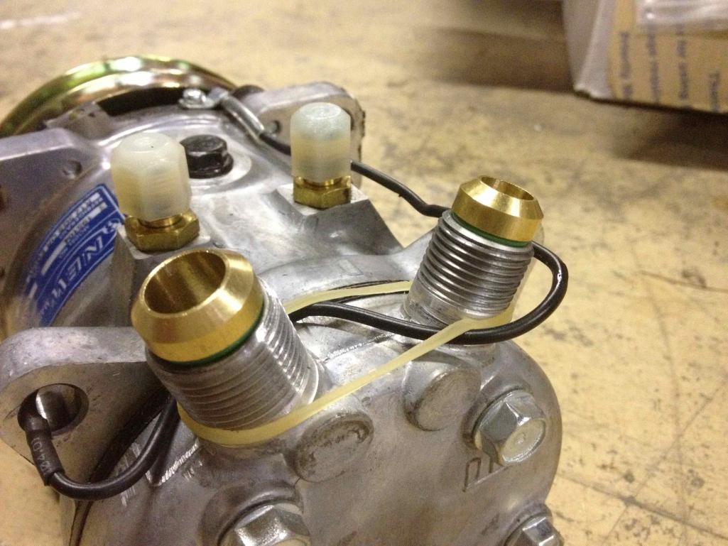
Receiver Drier:
The drier contains a desiccant that removes moisture from the system and it also stores extra refrigerant. This item is fairly cheap <$20 and should not be reused. There are a few options out there depending on where you want to mount it. You can find them in a variety of sizes and also ones for lying horizontally.
Original 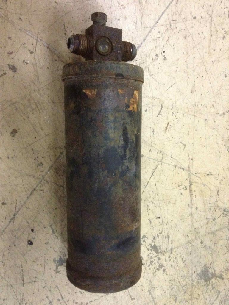
The drier I plan to use. Its a "short" version. It also has ports for using pressure switches.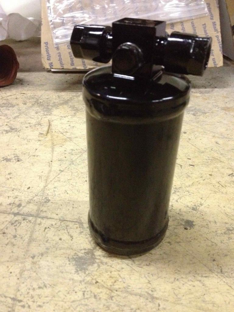
Wiring:
Below is a wiring diagram I found for the VPC System. I believe it was made by someone on this site (Thanks). The only change I’m going to add is the addition of a trinary switch on the drier. The trinary switch will cut off the compressor if the pressure is too low or too high and it will also engage the condenser fan after the pressure reaches a certain point. 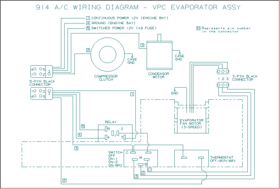
Posted by: dlee6204 Aug 22 2012, 08:05 PM
[Future Post]
Posted by: dlee6204 Aug 22 2012, 08:05 PM
Reference Pictures:
Posted by: billh1963 Aug 22 2012, 08:26 PM
I just removed my York compressor. I could "put it back together" to show how it mounts
Posted by: dlee6204 Aug 22 2012, 08:57 PM

I just removed my York compressor. I could "put it back together" to show how it mounts
Unless someone else chimes in, I would greatly appreciate it.
Posted by: dlee6204 Aug 22 2012, 09:02 PM
So for my build I will be starting from scratch. My car did not come with A/C. A detailed list of parts can be seen below. I ordered most of the stuff from http://www.nostalgicairparts.com/ I also had to order a few fittings from Coldhose.com however NostalgicAir owns the Coldhose site so its the same company. If anyone needs specific parts numbers I can provide those too as well.
I did buy my compressor on Ebay from johnjoysyl. I'll provide more details on some of the items later in the thread.
-Sanden 507 Compressor
-VPC Evaporator
-Short Style Center Console
-VPC Condenser Box
-Custom Compressor mount on top
-# 8 Straight Flare Fitting (1)
-# 6 90 Degree Flare Fitting (2)
-# 10 Straight Flare Fitting (1)
-# 6 90 Degree Female O-ring Fitting (1)
-# 6 Straight Female O-ring Fitting (1)
-# 10 90 Degree R-134a Charging Port Fitting (1)
-# 8 90 Degree R-134a Charging Port Fitting (1)
-Flare Expansion Valve (1)
-Shorty Standard O-ring Receiver Drier (1)
-Male Trinary Safety Switch For Electric Fans (1)
-Grommet Single #6 - #10 (10)
-Barrier A/C Hose # 6 Sold By The Foot (9)
-Barrier A/C Hose # 8 Sold By The Foot (13)
-Barrier A/C Hose # 10 Sold By The Foot (13)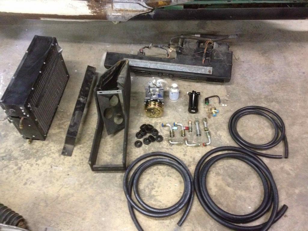
Posted by: dlee6204 Aug 22 2012, 09:08 PM
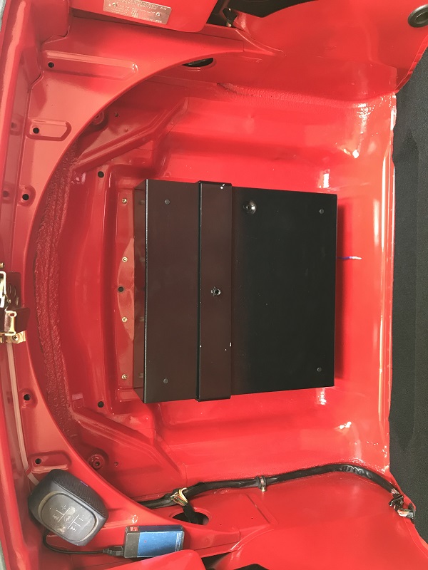
The first thing I did was install the front condenser. I didn't mind cutting a hole in my trunk so long as it was a clean install. Plus people cut holes in their trunks all the time for oil coolers, radiators, etc. so I didn't feel too bad cutting into my virgin floor.
About to make the cut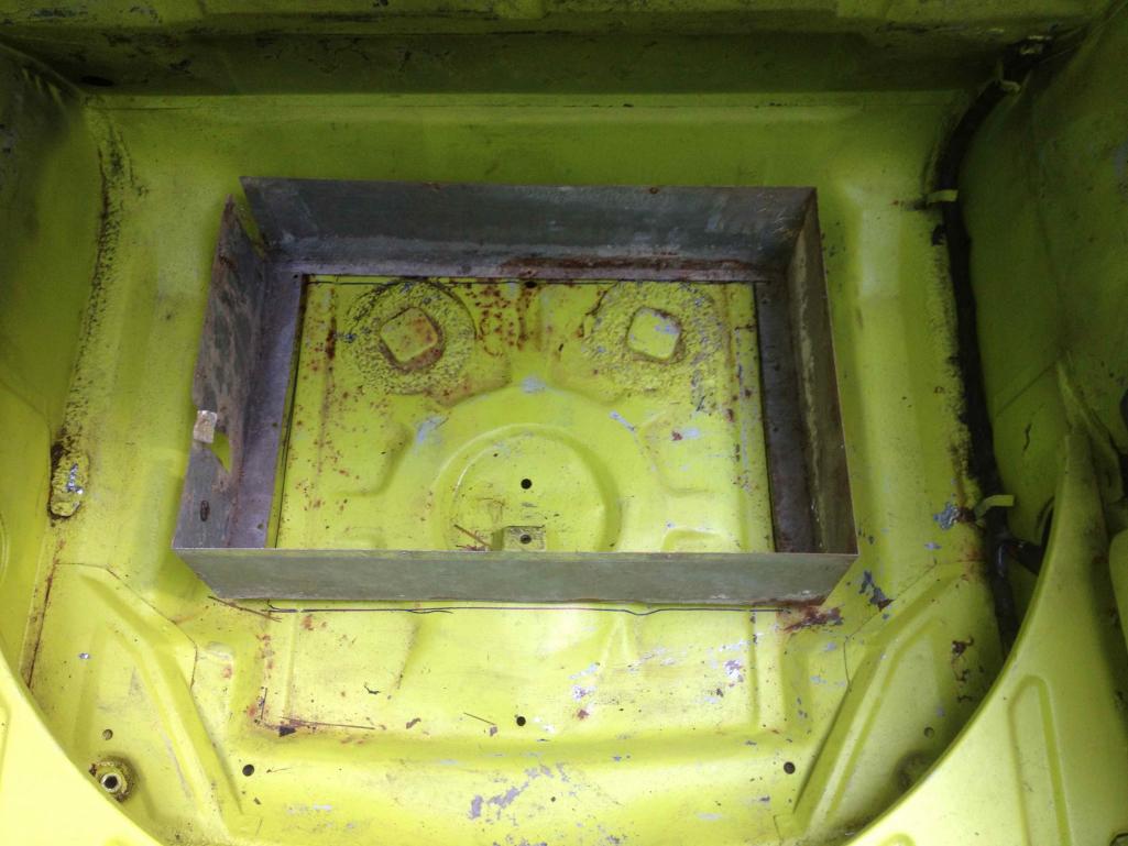
 I saved the cutout incase I ever want to reinstall the floor.
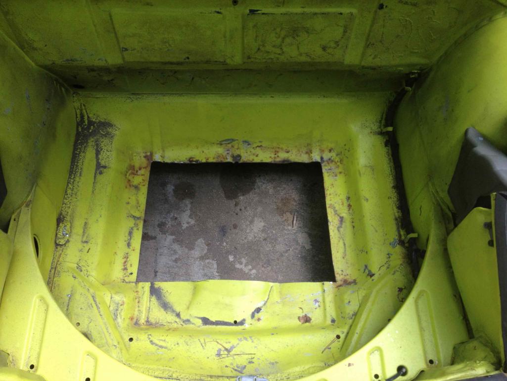
Installed. I still need to install some gaskets to keep water out.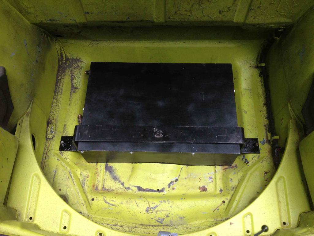
Posted by: wingnut86 Aug 22 2012, 09:49 PM
I checked into aftermarket systems for ACs last year. Jake Raby had installed one on his wife's Bug he put a Type IV in, I have images around here somewhere that his office manager shared with me. He had a new vendor in Florida build the setup for him. I contacted this gent just as he was putting an ops manual together around this, I actually offered to do the technical writing if he sent me a kit to play with on my 2.0. He never followed up on a final price and email he owed me, so I haven't any further detail. I think his outfit is close to where Joe's setup is for Series9 - Deland maybe.
He was using a similar setup to yours, new condenser, Sanden compressor, smaller & modern fan in the wheelhouse unit.
I'll try to find the details Friday. Jake's site may show his wife's car/engine bay, thinking it was top mounted as well - but it may have a DTM - can't remember currently.
Dave
Posted by: zambezi Aug 22 2012, 11:31 PM
Here are some of my condensor mountings. I am running the DPD system because that is how my car was bought new. I am not driving the car yet (still waiting for paint) but it is fully functional and have got 40 degrees out of the vents, and that is with an unsealed cabin with no seals anywhere.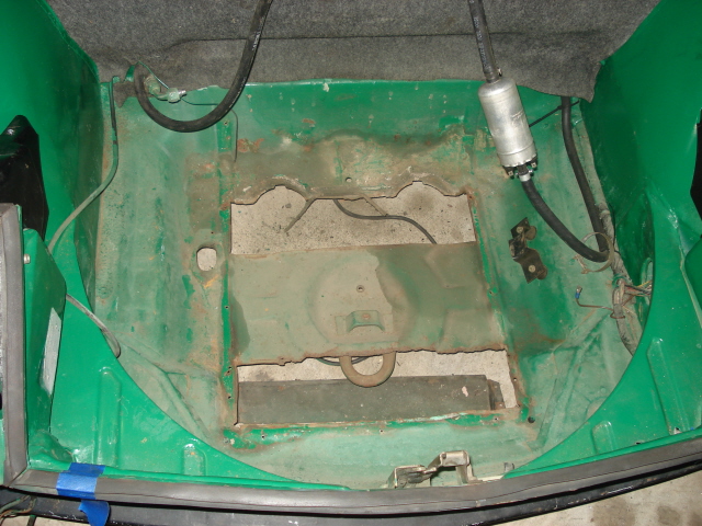
this was the before picture. What a hack job that was done at the dealerships huh!!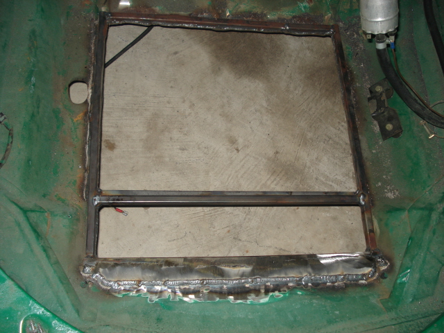
Here is how I braced and cleaned up the opening.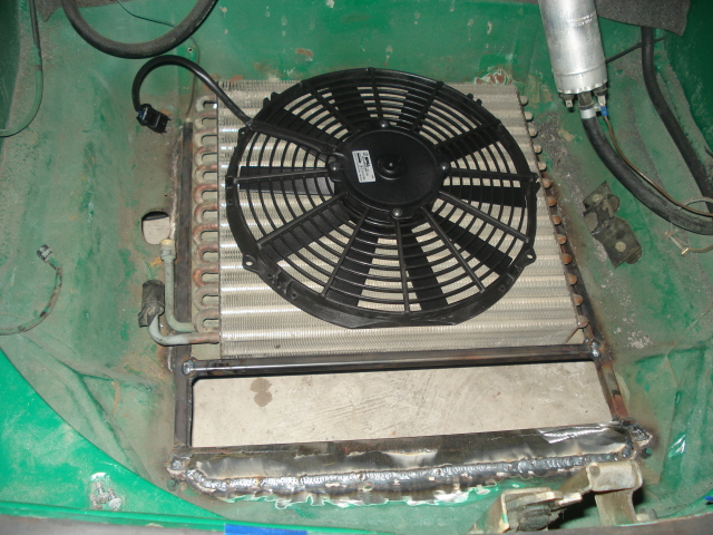
Here it is with the condensor test fit with the new SPAL cooling fan. It cover a much greater area and will flow a ton more air.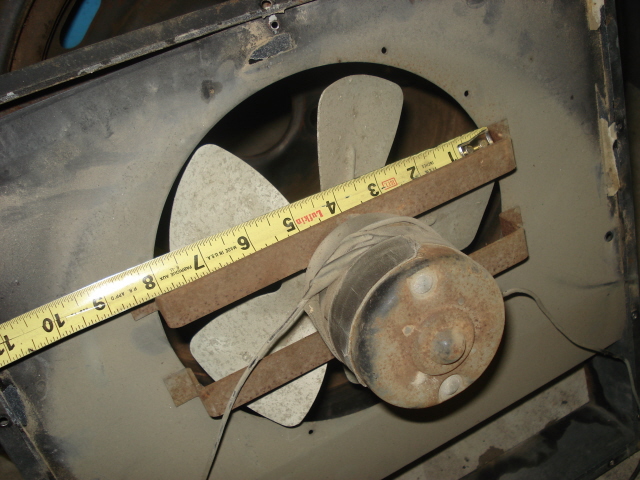
The original fan for comparison. Even the squirrel cage fan that comes with the VPC setup flows better than this.
I will have to get out to the shop and take some pics of the final setup showing hose routing and drier location. This is going to be a good thread and should be a great place for all the A/C configurations to be posted. I am curious how your smog pulley system will hold up and how much it is offset towards the front of the car. There is not a lot of room forward towards the firewall. My pulley works good but it is still very close. I would have more room if I was not running the factory sound pad (with a layer of dynamat extreme behind it as well).
I will try and get more pics loaded up in a day or two of the rest of it.
JIM
Posted by: JRust Aug 22 2012, 11:58 PM
Man I appreciate this. I will be setting up a/c in my LS1 conversion. I have the compressor & condensor saved from my donor camaro. I haven't messed with to much a/c so your thread is just what I needed  . Thanks
Posted by: Philip W. Aug 23 2012, 06:46 AM
 excellent thread to document for those of us that are contemplating this conversion to our non-A/C cars- being in the south, i really dont drive my 914 in the summer- 95-105 degrees for 3 month, the car just sits- i am looking forward to seeing this documented all the way thru the complete project,
it is sure to be add to the "Classics".
if you can share your parts lists and sources for such as the fittings etc, would be greatly appreciated!
What do you anticipate you final cost for the project will be?
Posted by: dlee6204 Aug 23 2012, 07:39 AM
if you can share your parts lists and sources for such as the fittings etc, would be greatly appreciated!
What do you anticipate you final cost for the project will be?
I'll be sharing all this information when I get a chance and get more organized.
Posted by: dlee6204 Aug 23 2012, 07:56 AM
I'd be interested in hearing how much clearance you had in front of your engine pulley. My smog pulley has a small diameter pulley and it has very little clearance with the front tin. I can't imagine having a larger diameter pulley.
My a/c compressor is already mounted and it fits perfectly center of the "hump" in the firewall so there is quite a bit of room. I'll show more on this later.
Posted by: 76-914 Aug 23 2012, 08:16 AM
![popcorn[1].gif](style_emoticons/default/popcorn[1].gif)
Posted by: TJB/914 Aug 23 2012, 08:49 AM
Drive pulley.
T
Attached thumbnail(s)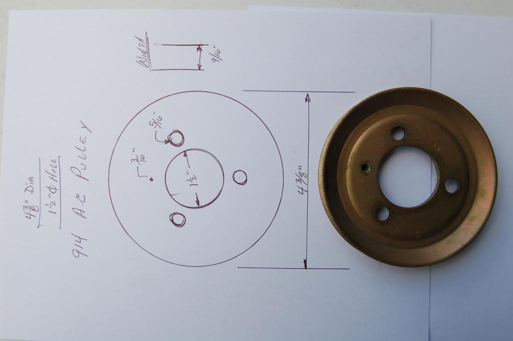
Posted by: andys Aug 23 2012, 09:51 AM
In a couple of days I can hopefully provide some photos of my AC install (LS1 conversion) that may be helpful to the -4 & -6 guys as well. I used an under dash evaporator (Hot Rod Air) that looks somewhat similar to the original dealer installed system (from memory of my '73, but that was more than 30 years ago). I opted to use reduced-diameter barrier hose which, as the name implies, the diameter (outside) is smaller than standard barrier hose. The smaller hose makes routing easier, and you don't have to punch such large holes. The fittings are more difficult to find, but Doc's Blocks (Stark Mfg) makes a whole array of there fittings; they recently stopped selling direct, so you'll have to contact them for a dealer. If you go with the reduced barrier hose, make sure your local AC shop has the correct crimping dies (most do not). Luckily, my local NAPA did have the correct ones, and did a great job.
Andys
Posted by: mtburman Aug 23 2012, 11:28 AM
It's important to watch spacing on the condenser enclosure/fan if you are going to retain the spare tire mounting on top of the cone. Too far back makes it difficult to set/remove tire.
Posted by: dlee6204 Aug 23 2012, 02:57 PM
In a couple of days I can hopefully provide some photos of my AC install (LS1 conversion) that may be helpful to the -4 & -6 guys as well. I used an under dash evaporator (Hot Rod Air) that looks somewhat similar to the original dealer installed system (from memory of my '73, but that was more than 30 years ago). I opted to use reduced-diameter barrier hose which, as the name implies, the diameter (outside) is smaller than standard barrier hose. The smaller hose makes routing easier, and you don't have to punch such large holes. The fittings are more difficult to find, but Doc's Blocks (Stark Mfg) makes a whole array of there fittings; they recently stopped selling direct, so you'll have to contact them for a dealer. If you go with the reduced barrier hose, make sure your local AC shop has the correct crimping dies (most do not). Luckily, my local NAPA did have the correct ones, and did a great job.
Andys
Interesting. Please keep us updated. Do you have any specs on the hoses? As in, what the OD is?
The size of regular hose is as follows:
#6 ID: 5/16", OD: 3/4"
#8 ID: 13/32", OD: 29/32"
#10 ID: 1/2", OD: 1"
Posted by: andys Aug 23 2012, 04:48 PM
Interesting. Please keep us updated. Do you have any specs on the hoses? As in, what the OD is?
The size of regular hose is as follows:
#6 ID: 5/16", OD: 3/4"
#8 ID: 13/32", OD: 29/32"
#10 ID: 1/2", OD: 1"
Doug,
Here's a chart of std and RBH sizes (kind of a lousey chart, but all I could find with a quick search).
http://www.ackits.com/c/Barrier/Barrier+Hose+-+Bulk.html
Andys
Posted by: dlee6204 Aug 23 2012, 04:53 PM
I updated post #9 with a more detailed list of parts.
Posted by: dlee6204 Aug 23 2012, 05:06 PM
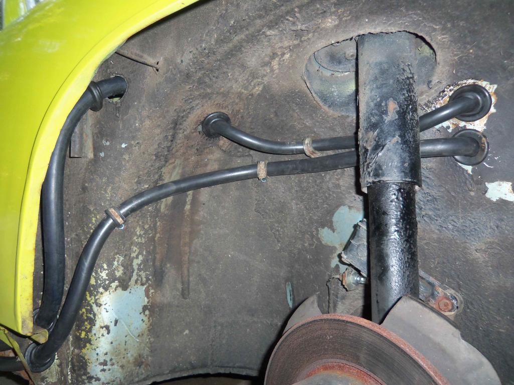
After getting the condenser in I began routing my lines and drilling holes. The grommets I used require a 1.5" hole. I ran my lines similar to that in an original system. There are probably better ways to route the lines however my setup works just fine. Plus they will probably get redone when a redo my car in a few years. I still have to button up the lines in a few areas. The pictures below are mostly during mockup.
I order 13ft of #8 and #10 hose and 9ft of #6 hose. I ended up with about a foot left of each so it was just the right amount. 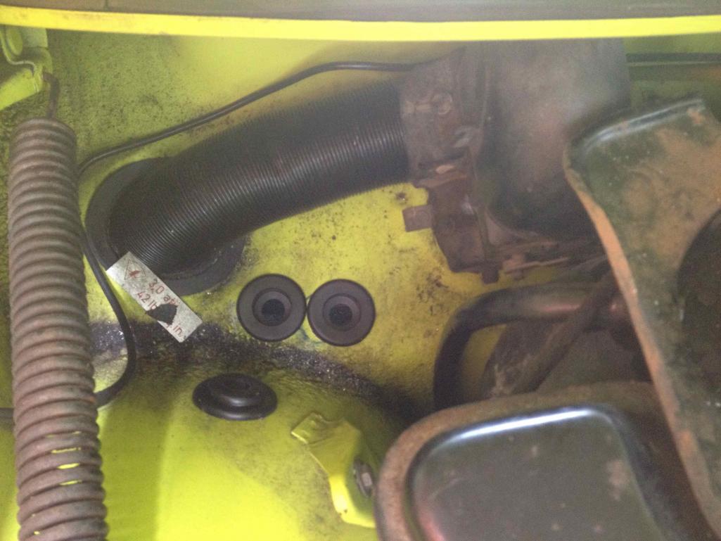
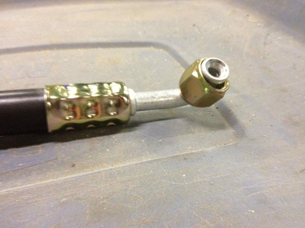
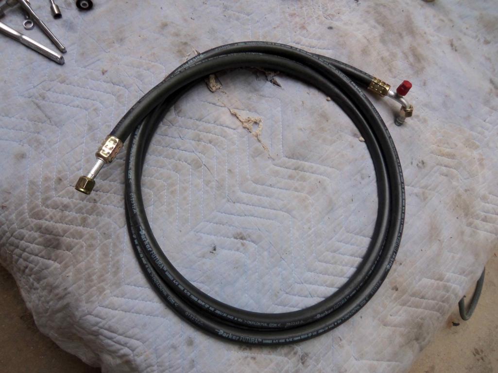
Posted by: dlee6204 Aug 23 2012, 05:13 PM
And while we are on the subject of hoses.... I made all of my own hoses. I started by routing the line, marking how much I needed, removed the line, installed the end fittings, and then reinstalled the lines adding grommets where needed. 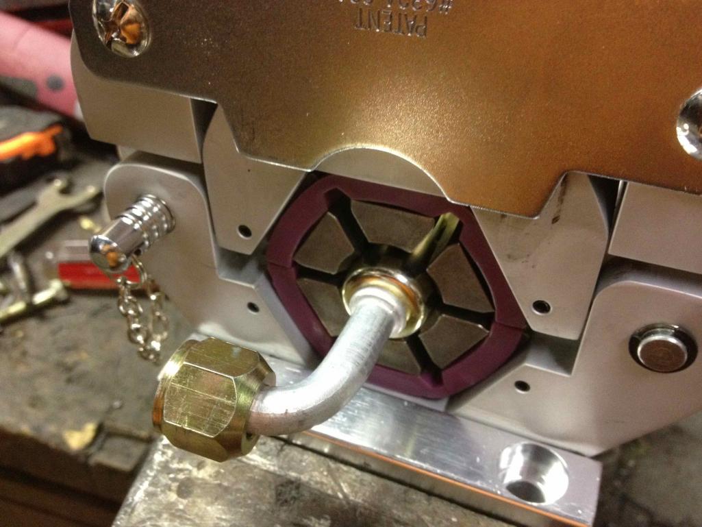
Posted by: dlee6204 Aug 23 2012, 05:18 PM
The Evaporator install was pretty straight forward so I didn't take many pictures. The Evap unit attaches to the underdash pad and then two brackets on either side to hold it up. My unit isn't in the greatest shape but works. All the vents are broken in some way so if anyone has any spare vents they would like to get rid of, I could use em.
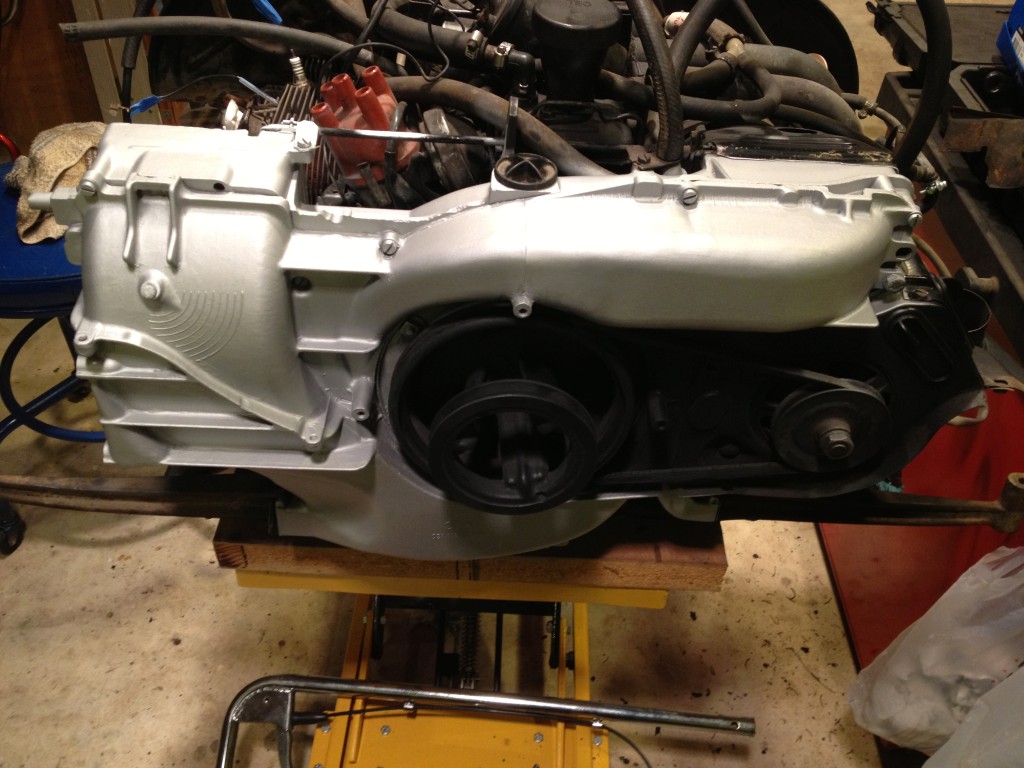
Posted by: dlee6204 Aug 23 2012, 06:33 PM
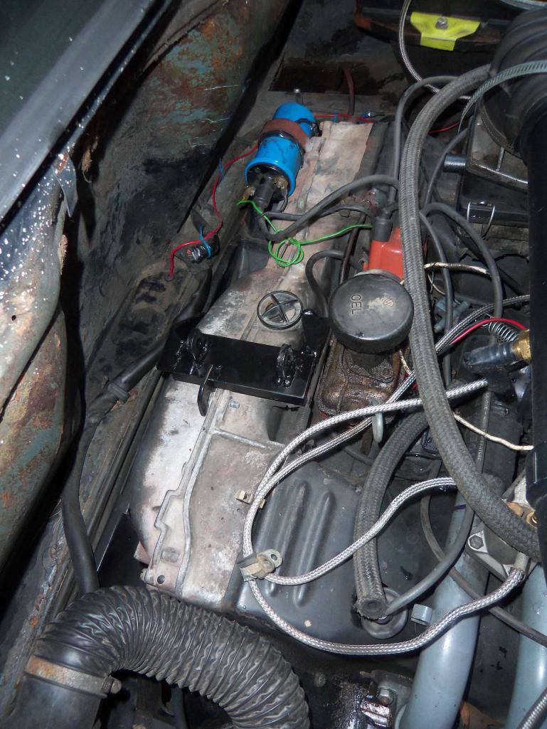
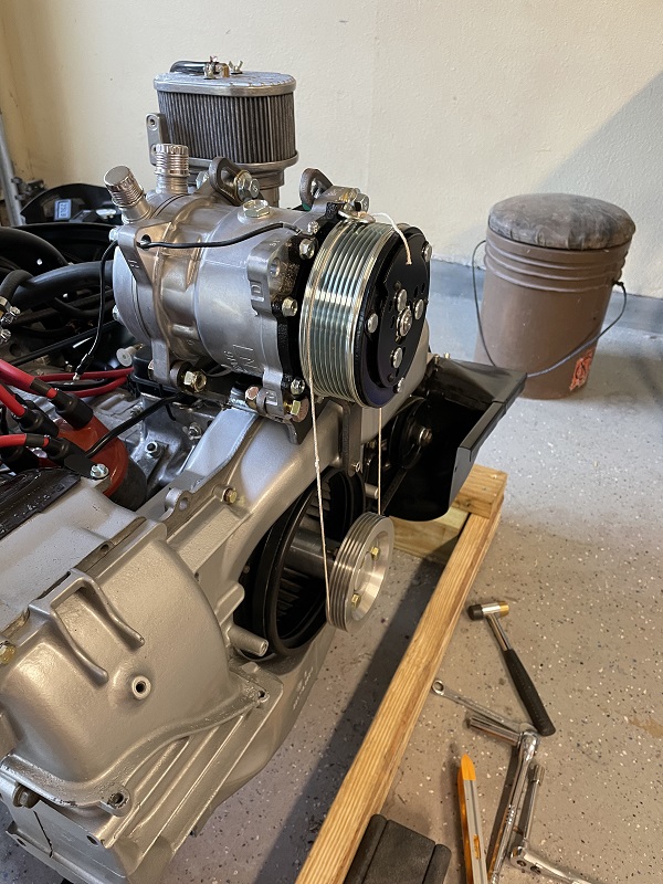
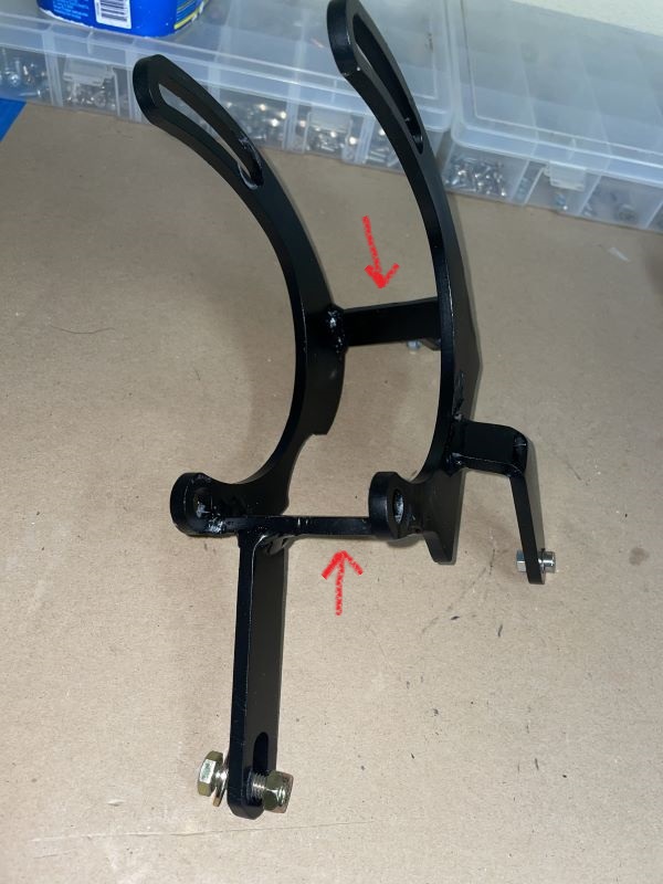
Onto the compressor... I decided to go with a top-mounted unit utilizing a smog pulley assembly to drive it. I had big plans to have this nice professional looking mount that I would be proud of... and the parts I needed ended up being backordered. I got tired of waiting so I made my own from scratch. Later down the road I might update the mount.
Here is the setup I came up with.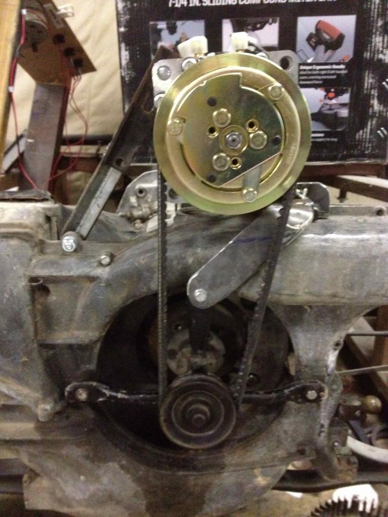
Here is the mount. It might not look like much but its solid as a rock.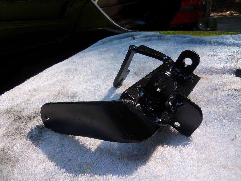
The adjustment piece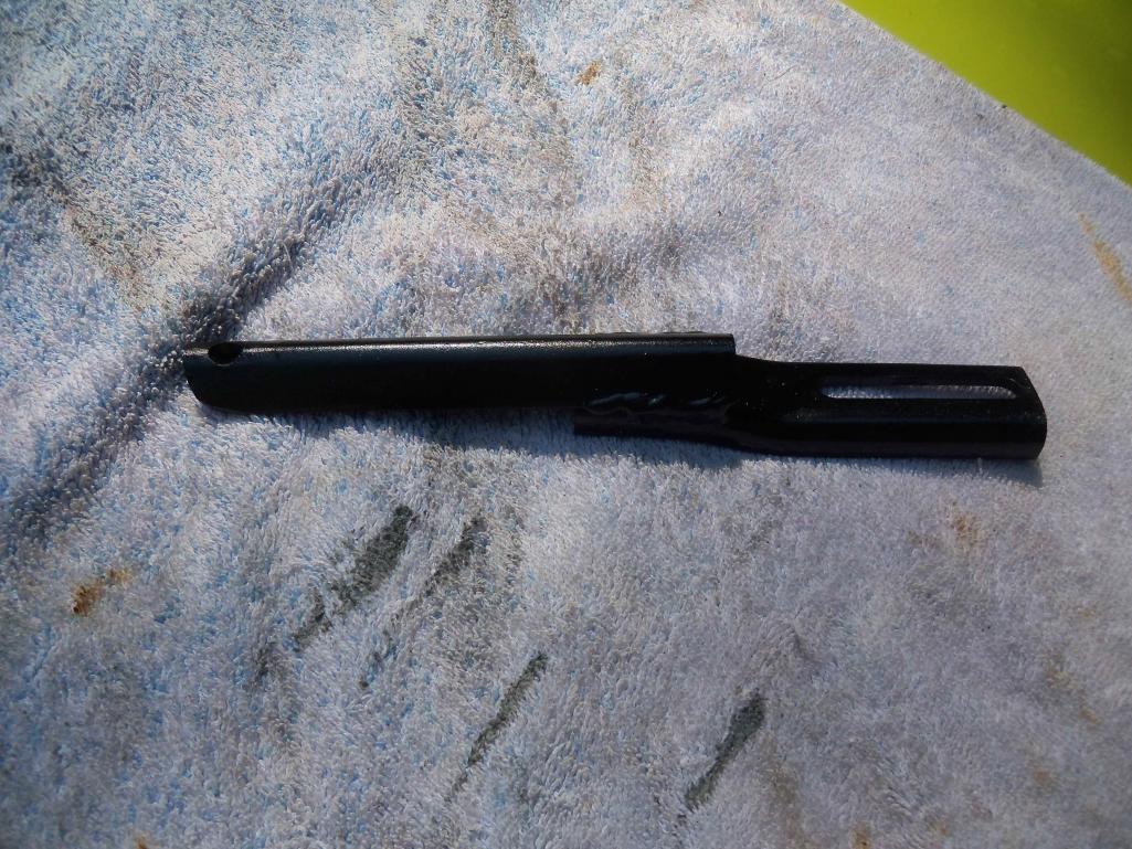
The pulley assembly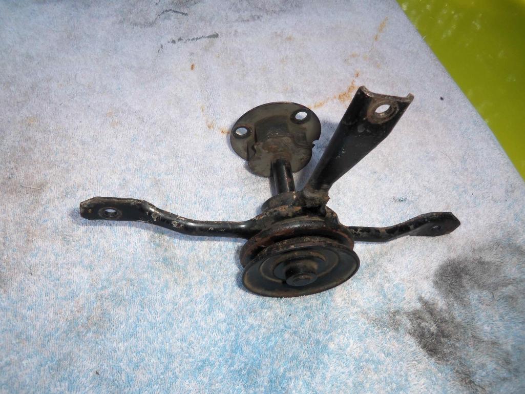
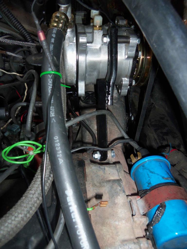
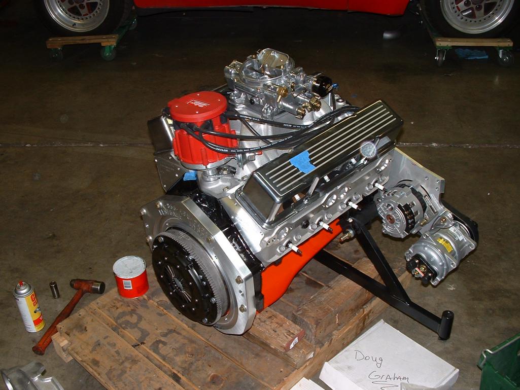
Posted by: dlee6204 Aug 23 2012, 06:38 PM
Some more pictures on the test engine.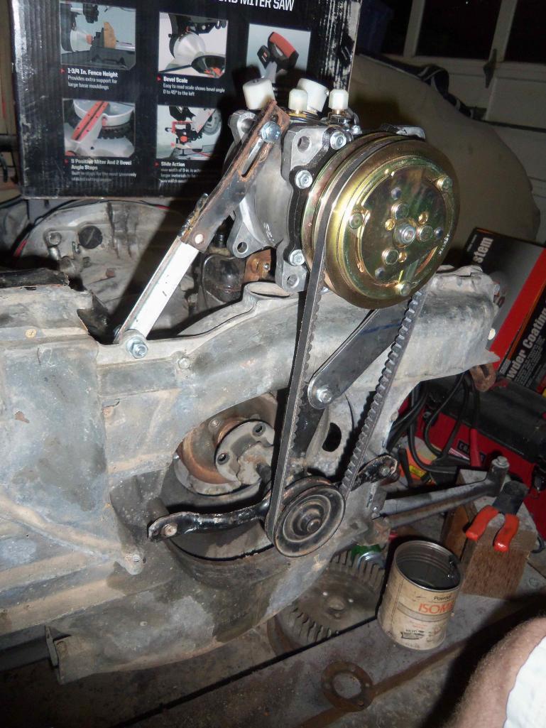
I ended up not needing to relocate the filler. 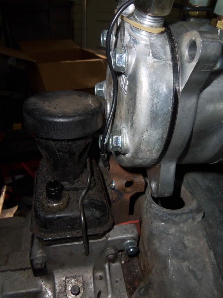
Posted by: dlee6204 Aug 23 2012, 06:43 PM
More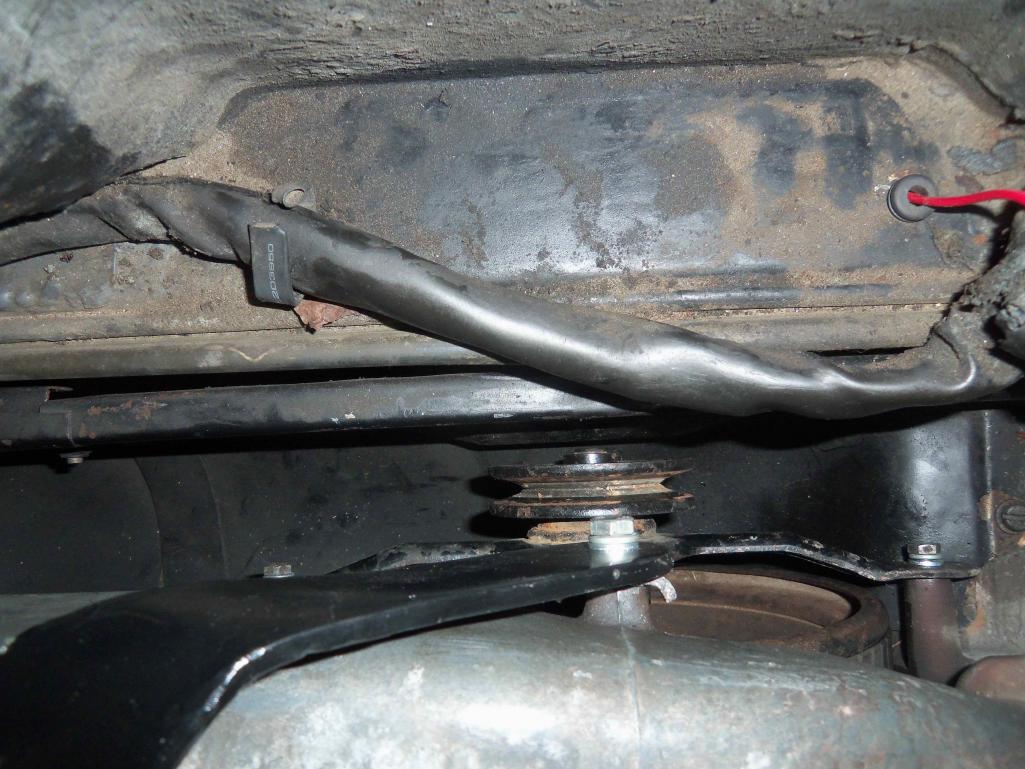
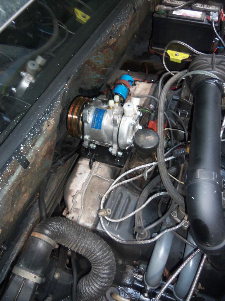
Finished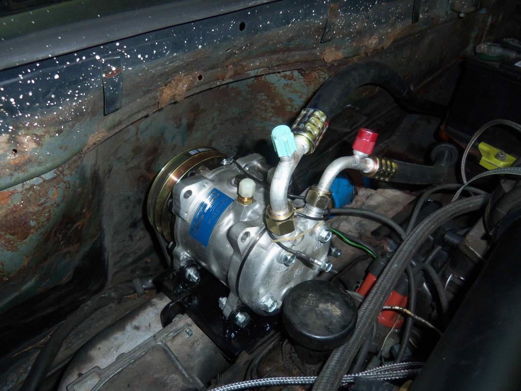
Posted by: Jeff Bowlsby Aug 23 2012, 06:57 PM
Do you have to remove the compressor to time the engine?
Posted by: FourBlades Aug 23 2012, 06:59 PM
Great thread, thanks for posting this.
John
Posted by: dlee6204 Aug 23 2012, 07:08 PM
Do you have to remove the compressor to time the engine?
Maybe... The timing port was difficult to work around so I had to do the best I could. I think I can use a small mirror to see the timing marks but if I have to remove the compressor, its three bolts and takes 2 minutes.
Posted by: cgnj Aug 23 2012, 07:14 PM
Do you have to remove the compressor to time the engine?
Maybe... The timing port was difficult to work around so I had to do the best I could. I think I can use a small mirror to see the timing marks but if I have to remove the compressor, its three bolts and takes 2 minutes.
I use the timing mark on the flywheel. I never time off the fan.
Posted by: hot_shoe914 Aug 23 2012, 07:20 PM
Best damn thread EVER in the garage!

Posted by: dlee6204 Aug 23 2012, 07:27 PM
Good idea!
Posted by: dlee6204 Aug 23 2012, 07:33 PM
The best thing about this whole setup is that IT WORKS. More to come soon.
Posted by: gothspeed Aug 23 2012, 09:09 PM
fantastic thread 
when my car gets done, I am gonna want A/C in it ..... thanks for documenting this  !!!
!!!
Posted by: metalmorphosis Aug 23 2012, 09:19 PM
Awesome Doug can't wait to go for a ride sometime w the a/c blasting.
Gabe
Posted by: zambezi Aug 23 2012, 09:52 PM
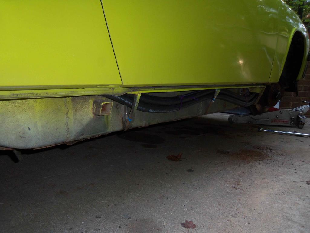
My hoses were originally run that way. In your picture you can see the inner fender well has rub marks where the tire has rubbed in the past at full lock. My car does too and I am running 17 inch turbo twists now which are very close to rubbing the fender well on full lock even with my custom spacers. I routed my hose up and over the tire and added two hose mounts to keep it in place. In my pics you can see the hose enters the trunk under the headlight up front.
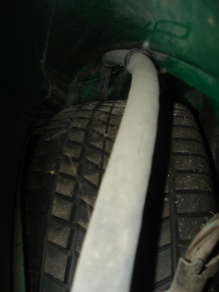
don't mind the spider webs. here is the hose running up over the tire.
the two hose mounts are riveted in the seal channel and will be hidden by the seal.
The hose enters under the headlight into the trunk.
Here is my completed trunk area. I also am running the drier in the trunk.
Posted by: zambezi Aug 23 2012, 10:02 PM
Here are the other pics I took tonight of the compressor mounted and the hoses run. 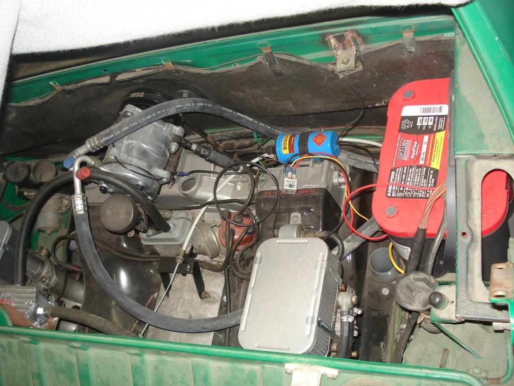
In this picture you can see the timing plug is removed and there is access to view the timing marks (even on a stock setup you need to be a contortionist to see directly down there). You can also see I relocated my oil filler higher and angled back for easier access.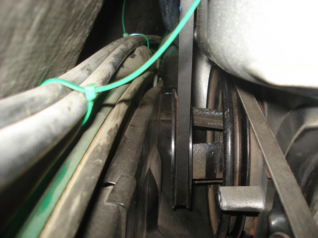
Here is the front pulley. Lots of room for the engine tin for belt changes.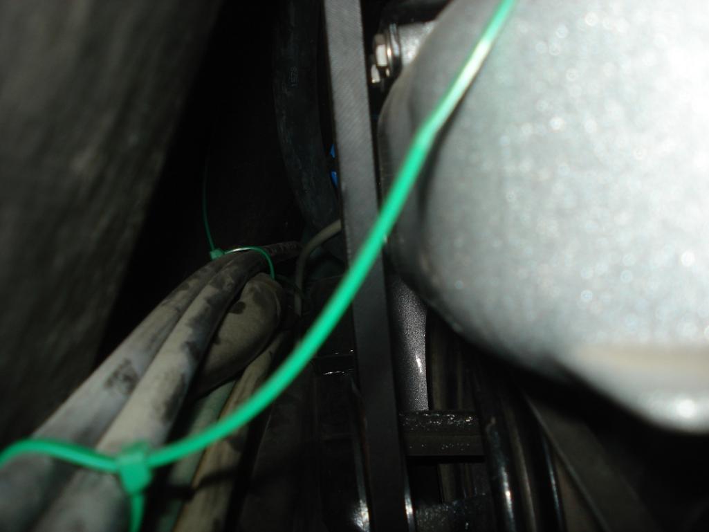
The belt JUST hugs the front fan housing.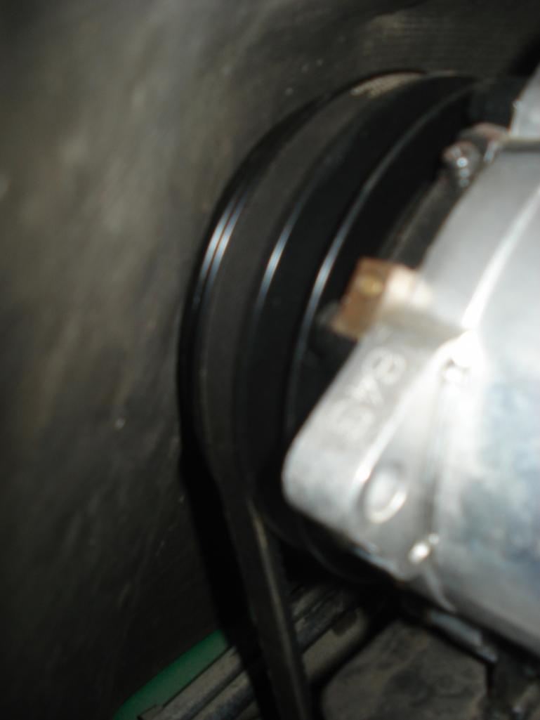
Here you can see how close the compressor pulley is to the factory sound pad. In your setup I noticed you have no sound pad yet. If you put one back I am sure you will be close like mine. It is close but still just clears and I want that heat and sound barrier for the cabin so it is worth it.
Posted by: zambezi Aug 23 2012, 10:09 PM
These pictures have been posted on this forum before but I thought I should post them here again so we can keep this info all together. This thread is going to be a good place for all the information to be in one place. I am sure all this info will help someone. 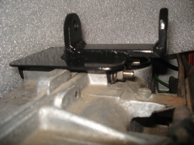
Here is my bracket.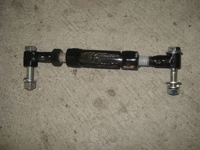
Here is my turnbuckle adjuster (left and right hand threads).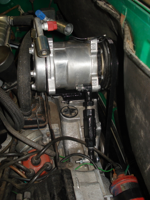
Here is the turnbuckle mounted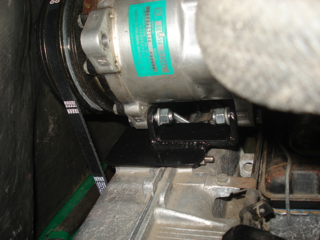
The other side of the mount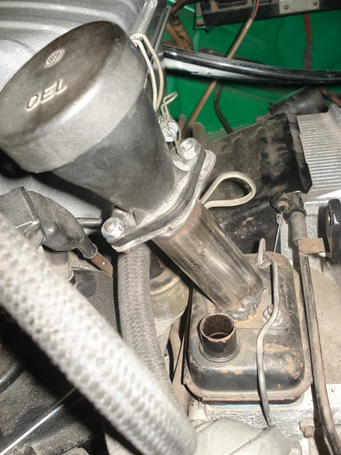
My oil filler modification.
Posted by: dlee6204 Aug 24 2012, 08:17 AM
Thanks for the pictures. I think my setup is a little closer to the firewall than yours. I have a little more clearance between the belt and fan shroud.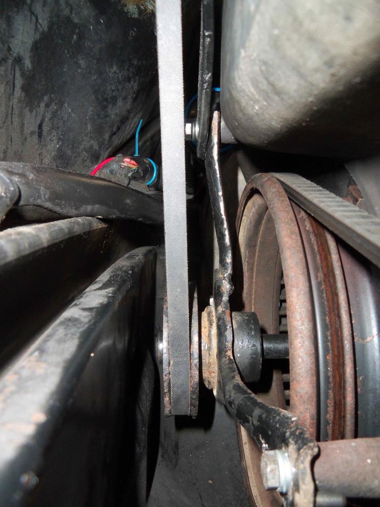
I have a little under 2 inches to the firewall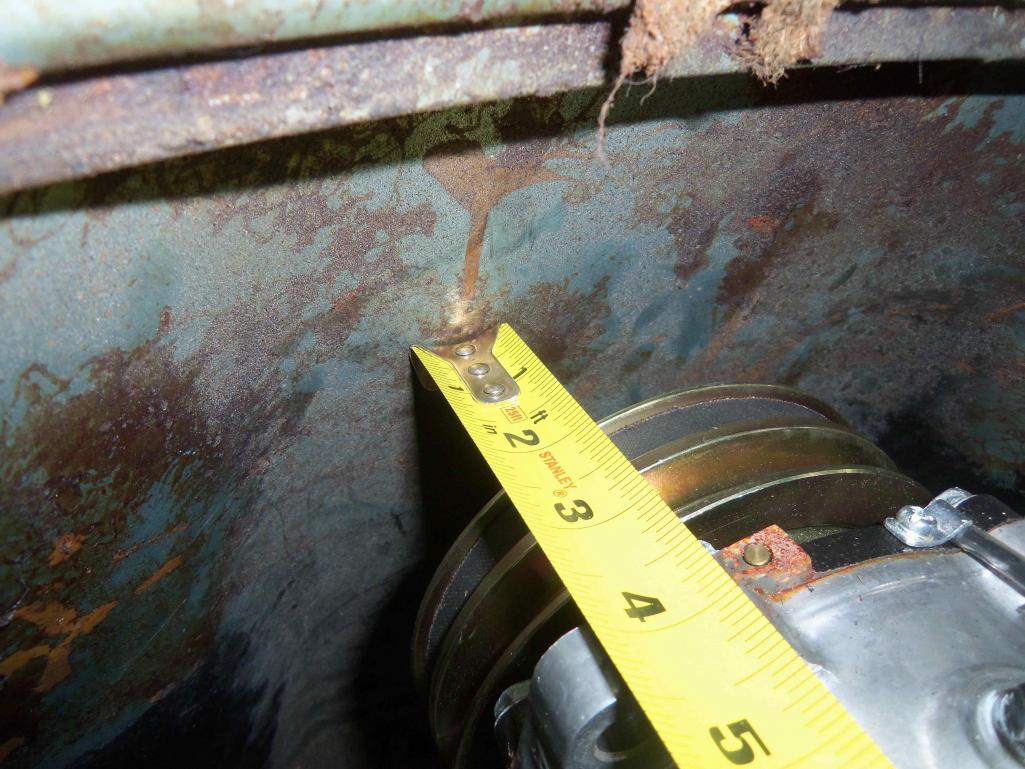
Posted by: Cohibra45 Aug 24 2012, 08:46 AM
Definitely needs to be in the tech articles when complete!!!
Posted by: andys Aug 24 2012, 09:59 AM
I know I'm delinquent with posting photos of my AC install, so meanwhile I'll describe how I routed my hoses as it differs from most. I ran my #6 and #8 hose from the front trunk low on the passenger side through the bulkhead, under the fuel tasnk, then into the foot well which give me a direct shot with the #6 hose to the expansion valve on the evaporator. The #8 and the #10 (suction side from the evap) travel along passenger side floor Adel clamped to the corner at the floor/long intersection. The hoses are hidden by the carpet, and are un-noticeable (I know, I need to post some photos). The #8 and #10 continue to the firewall where I have 90 degree hose ends with charge ports coupled to two bulkhead fittings. These are positioned such that they enter the engine bay below the tin just under the hell hole area. The one photo I do have is durring the mock-up stage.....the charge ports are no longer where you see them in the pic.....This gives you an idea of the routing to the LS1 compressor.
The reason I did it as described above, is I wanted to avoid running the AC hoses in the wheelwell (wide front tires there), as well as minimize the number of holes punched through the various panels, etc.
Andys
Attached thumbnail(s)
Posted by: dlee6204 Aug 26 2012, 08:12 PM
I thought I would share some additional information... The weight of stuff! 
York Compressor w/ mount- 29.6 LBS 
Sanden 507 Compressor- 14.4
Evaporator Unit- 13.2
Condenser Unit- 20.4
Receiver Drier- 1.4
Posted by: 76-914 Nov 7 2012, 08:58 PM
Any new developments?
Posted by: dlee6204 Nov 7 2012, 09:20 PM
I ran into a few small issues dealing with the smog pulley... due to the small pulley size on the smog setup, it creates a a few issues when trying to run an A/C compressor... low compressor rpms at idle and a large drop in rpms when idling and engaging compressor. This was a concern I had from the beginning but I wanted to test it out and see how much it would affect the operation. I currently have another solution in the works and I was going to update this thread once I get the pieces together. My next setup utilizes a stock A/C pulley offset a couple inches in front of the engine. Hopefully I will have more to add soon.
Posted by: dlee6204 Nov 7 2012, 09:27 PM
I also have a few more changes to make to the system before next summer. Not really necessary but just for fun.
-I will likely be changing the front condenser setup most likely by a better condenser, better fans, and hopefully still fitting in the space in the trunk.
-I will probably update the compressor mount.
Posted by: dlee6204 Nov 7 2012, 09:27 PM
Oh and here is a thread by andys on a different approach to hose routing.
http://www.914world.com/bbs2/index.php?showtopic=193697&hl=
Posted by: 76-914 Nov 8 2012, 08:25 AM
Just wondered. I will be doing a Suby conversion soon and will want to add A/C. I think I can mimic your install to some degree and hopefully have A/C, also. Thanks for the write up.
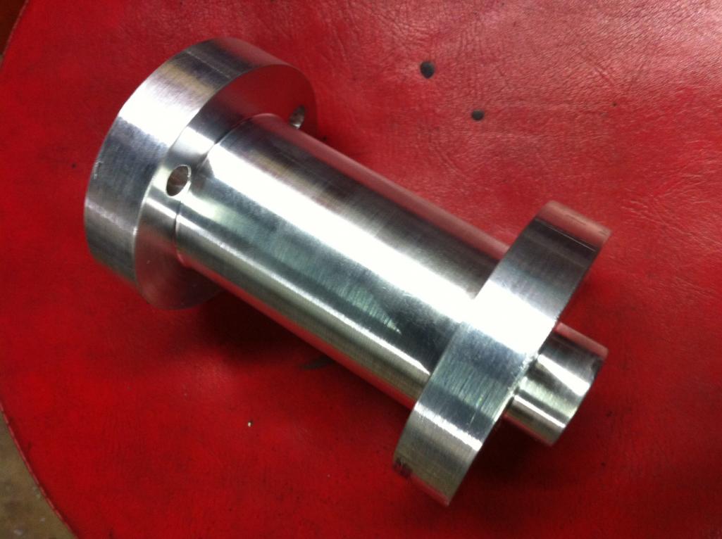
Posted by: dlee6204 Nov 25 2012, 04:12 PM
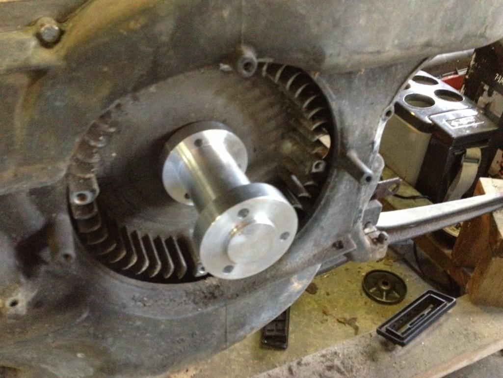
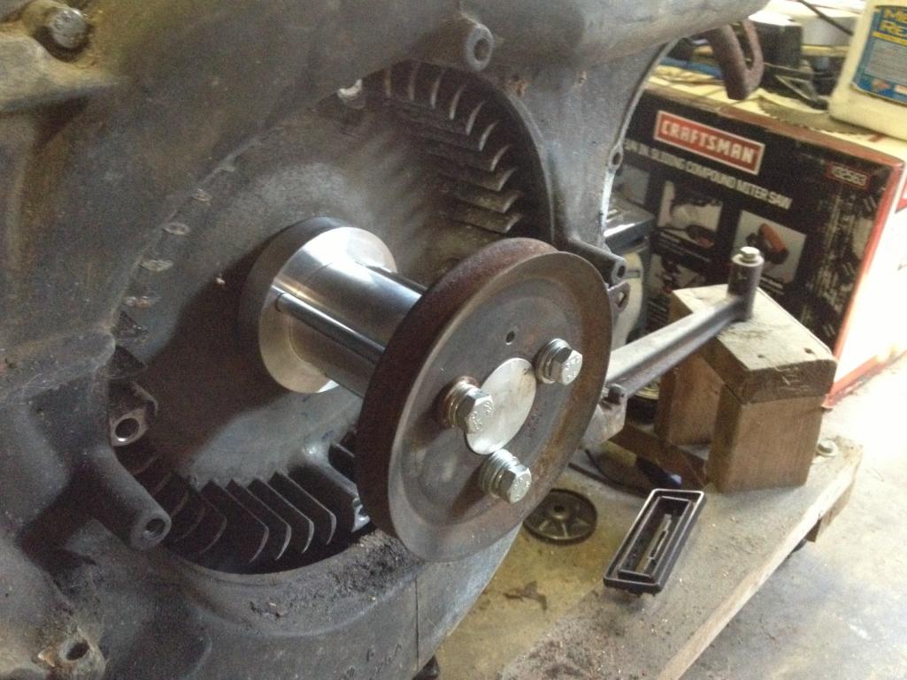
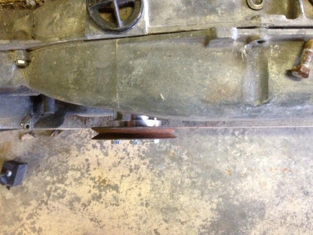
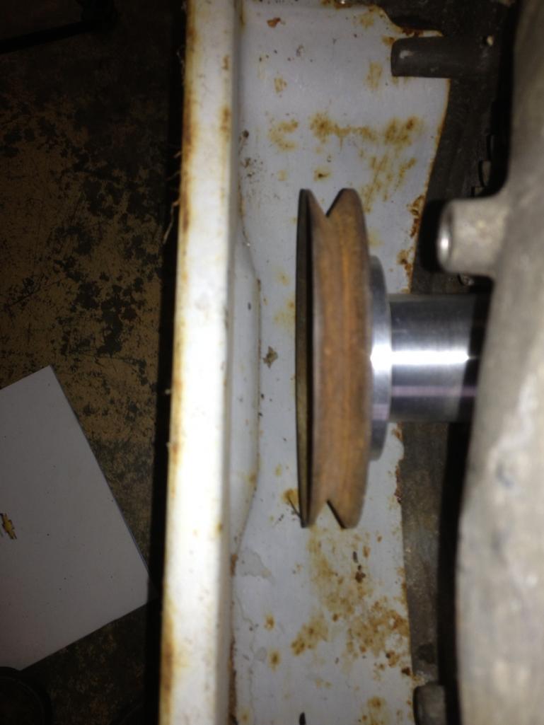
I made some progress on my A/C pulley. As I stated earlier, I wanted to use a stock a/c pulley mounted a couple inches off the front of the crank. My solution was to machine an adapter which can be seen below. It's machined on both ends so the pulley and adapter are both centered. Right now it's just a prototype. It has plenty of clearance and I tried to bring it in as close as possible leaving enough clearance for the belt against the shroud. I want to try and improve this design and eliminate the need for 7"+ through bolts and also to make it as light as possible.
Posted by: zambezi Nov 25 2012, 05:09 PM
looks like a great design. very similar to my cast pulley but a lot lighter I'm sure. Why not use some short allen head bolts at the fan side and drill and tap for some independent bolts at the pulley side. No need to make a new piece just re-clock the three bolt holes in the outer end by the pulley. You may need to turn down the center section slightly to clear the heads of the allen head bolts though.
Posted by: stateofidleness Nov 25 2012, 07:05 PM
Cool Thread! Makes me appreciate my "factory" install even more. I have the passenger side, top-mounted compressor you talked about on mine. Nothing was cut or altered in the engine compartment. I think it was installed in Houston.
Is there a record of how many cars were "AC'ed" after delivery to the states?
Posted by: dlee6204 Nov 25 2012, 07:40 PM
Do you have any pictures of it? How is it driven off the front?
Posted by: stateofidleness Nov 25 2012, 07:46 PM
I'll see if I can snap some pics of it. It's hard to see as it's pretty tightly crammed in there it seems.
Posted by: dlee6204 Nov 25 2012, 08:06 PM
looks like a great design. very similar to my cast pulley but a lot lighter I'm sure. Why not use some short allen head bolts at the fan side and drill and tap for some independent bolts at the pulley side. No need to make a new piece just re-clock the three bolt holes in the outer end by the pulley. You may need to turn down the center section slightly to clear the heads of the allen head bolts though.
That's essentially what I'm after. I'm also trying to get the weight down even more. Currently it's about 1.6lbs and could be less. I had a few people interested in these so the development continues.
Posted by: ScoopLV Nov 26 2012, 02:12 AM
Ugh... this is something I'd totally love to do. And I even have the motor out right now, getting a rebuild. But my wife has already told me that I should just call my car "Money Pit" instead of "Rocinante."
Considering I live in the Mojave desert, though, I should probably just have it installed now while I can. It's a shame that your custom mounts aren't available with the compressor, dryer, evaporator and the hoses in kit form.
Maybe I'll just put a cooler of dry ice in the car for the months of July and August? Breathing is overrated, after all...
Posted by: gothspeed Nov 27 2012, 06:43 PM
When I eventually get to the A/C ............ I was going to make a pulley adapter similar to the one you have prototyped ...... but as mentioned, try to have bolts on each end instead of the long versions. So judging from the progress you are making ....... looks like I will just get one from you, when the time comes .....
Posted by: dlee6204 Dec 15 2012, 08:55 AM
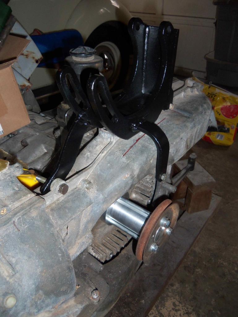
I just finished making a new mount. I'm a lot happier how this one turned out. I bought a universal mount (which doesn't fit the 507 too well  ) which I modified to fit. The nice thing about this is the ease of adjustment since its all once piece.
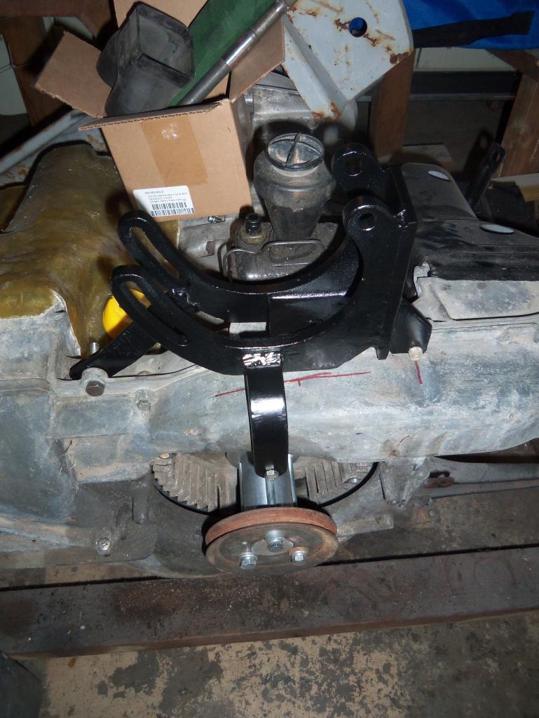
Posted by: dlee6204 Dec 15 2012, 08:56 AM

Posted by: 76-914 Dec 15 2012, 09:16 AM
Looking good in the hood my friend.
Posted by: wingnut86 Dec 15 2012, 10:56 AM
Agreed
So, what's the weakest link in the A/C system?
I'm thinking ahead here:
1- condenser flow enough?
2- underdash unit is how efficient?
3- how much current draw from under dash motor?
4- we already know the newer Sanden is light-speed ahead in design and operation
5- wondering what the total power loss is to system overall, knowing it's better than 42 year old design
Hot and humid southern summers make or break the Type IV from experience.
Again, replaying devil's advocate here more for my sanity...
Dave B.
Posted by: stateofidleness Dec 15 2012, 01:39 PM
Finally got to the car last weekend and snapped some pics of the compressor on my '73. It also looks like once the bolts are undone (I counted 4), that it would actually have enough hose length to be able to rest it on the rear deck lid. Planning on dropping the engine soon and was worried about suspending it, but seems like it'll sit up there nicely during the drop.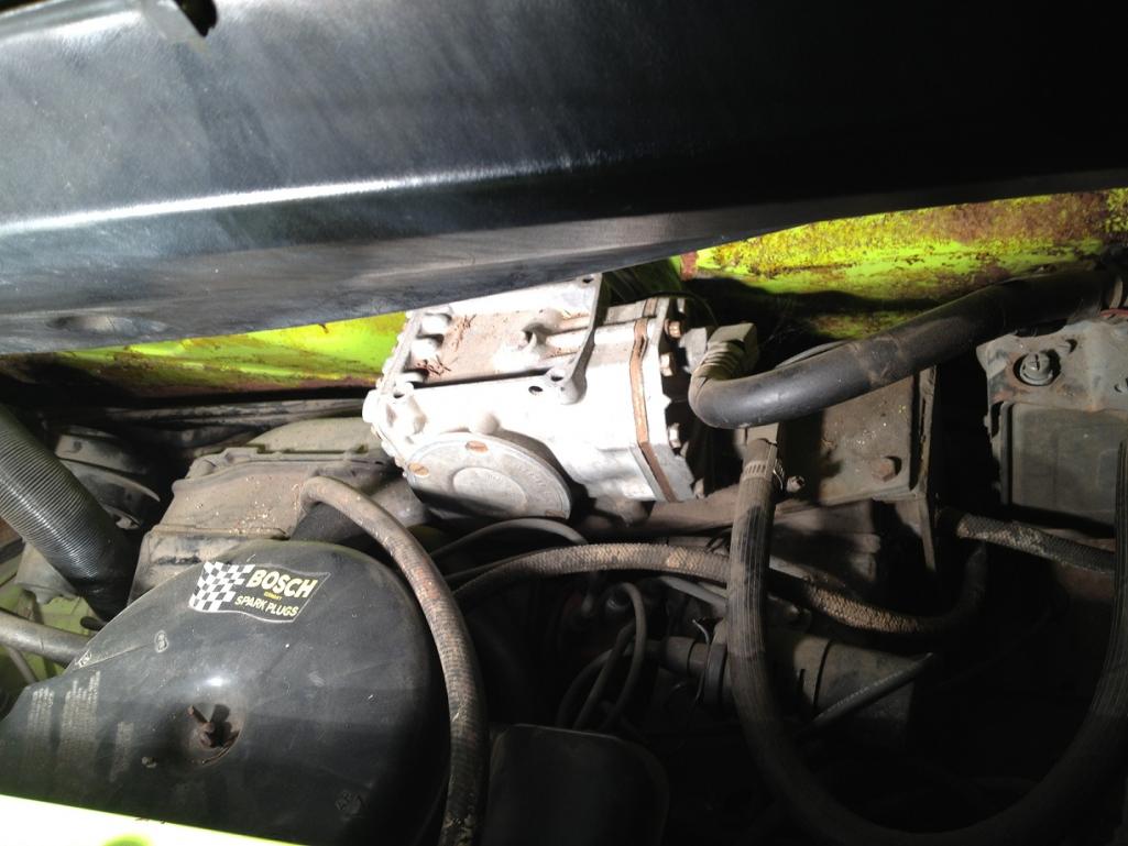
Posted by: zambezi Dec 15 2012, 09:35 PM
I am curios to know what pulley you have to drive the york. It looks like it would be a similar setup to mine. When you get the engine dropped take a pic of the pulley or aim the camera in there now and try and get a pic off.
Posted by: dlee6204 Dec 15 2012, 09:40 PM
Agreed
So, what's the weakest link in the A/C system?
I'm thinking ahead here:
1- condenser flow enough?
2- underdash unit is how efficient?
3- how much current draw from under dash motor?
4- we already know the newer Sanden is light-speed ahead in design and operation
5- wondering what the total power loss is to system overall, knowing it's better than 42 year old design
Hot and humid southern summers make or break the Type IV from experience.
Again, replaying devil's advocate here more for my sanity...
Dave B.
When I first started this project, my initial intent measure and evaluate the the various efficiencies of the system and its components and play around with different options (Its the engineer in me). I'll probably still play around with it more once the weather gets warm again. Right now I would assume the limiting factor to be the airflow over the condenser and/or condenser size specially when converting to r134.
Posted by: dlee6204 Dec 15 2012, 09:43 PM
stateofidleness, Thanks for the pics.

Posted by: wingnut86 Dec 15 2012, 11:17 PM
I found the link to the company that built Jake Raby's setup for his wife's Super Beetle, as well as one they show for a bus on their site.
Link provided:
http://www.gilmore-enterprises.net/Air/Bus.htm#
Looks like he still hasn't updated the kit he built for the 914, as the site link is still in progress for our cars.
Good images to check out though.

Posted by: rfuerst911sc Dec 16 2012, 04:32 AM
I plan to make a AC system for my GT clone sometime in the future. I have a Sanden compressor not sure it it's a 507 or 508. The trick will be a mount to use on my 3.0 six. I also plan on using a condensor from a Porsche 993 and install it in front of the right rear tire in the fender well. I think I can get it in there with a Spal fan and have good air flow. That would help keep the hose run shorter. Regardless of refrigerant type I will use o-ring fittings as I think they seal better than flare. This post has given me a few ideas thanks.
Posted by: ClayPerrine Dec 16 2012, 12:17 PM
Finally got to the car last weekend and snapped some pics of the compressor on my '73. It also looks like once the bolts are undone (I counted 4), that it would actually have enough hose length to be able to rest it on the rear deck lid. Planning on dropping the engine soon and was worried about suspending it, but seems like it'll sit up there nicely during the drop.
Take the battery out of the car and put the compressor in the battery tray. The hoses will be long enough, and you don't risk scratching or denting the rear deck lid.
Posted by: stateofidleness Dec 16 2012, 07:39 PM
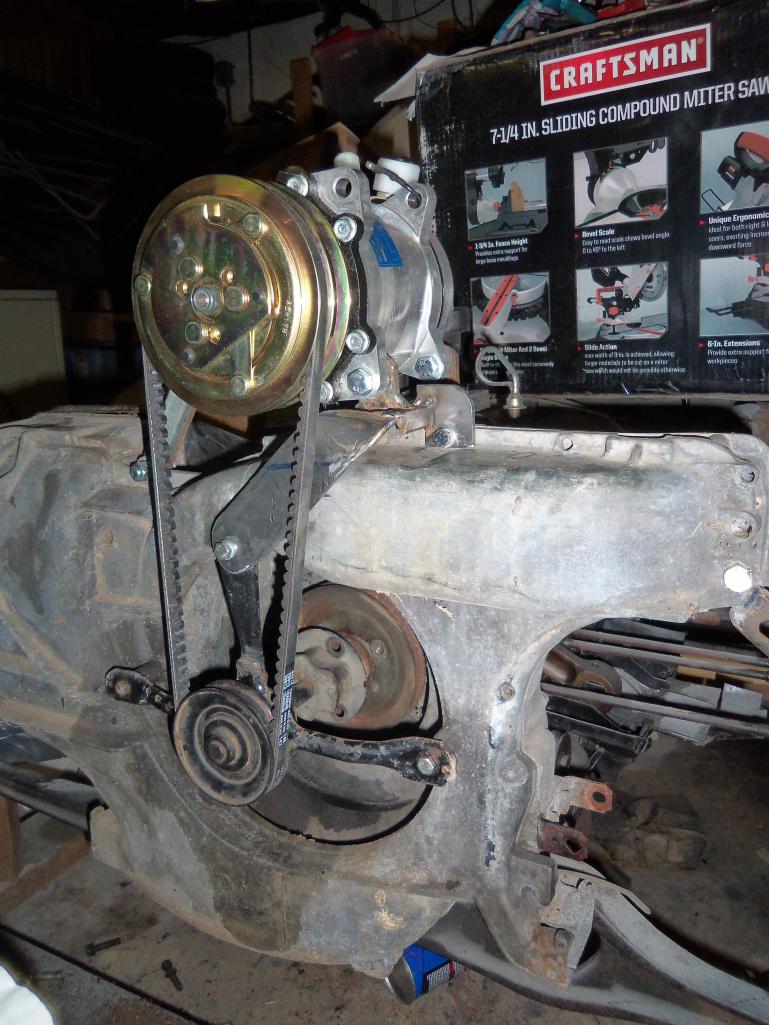
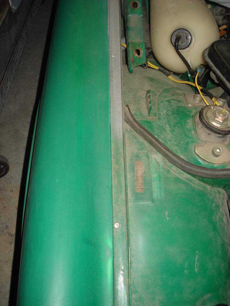
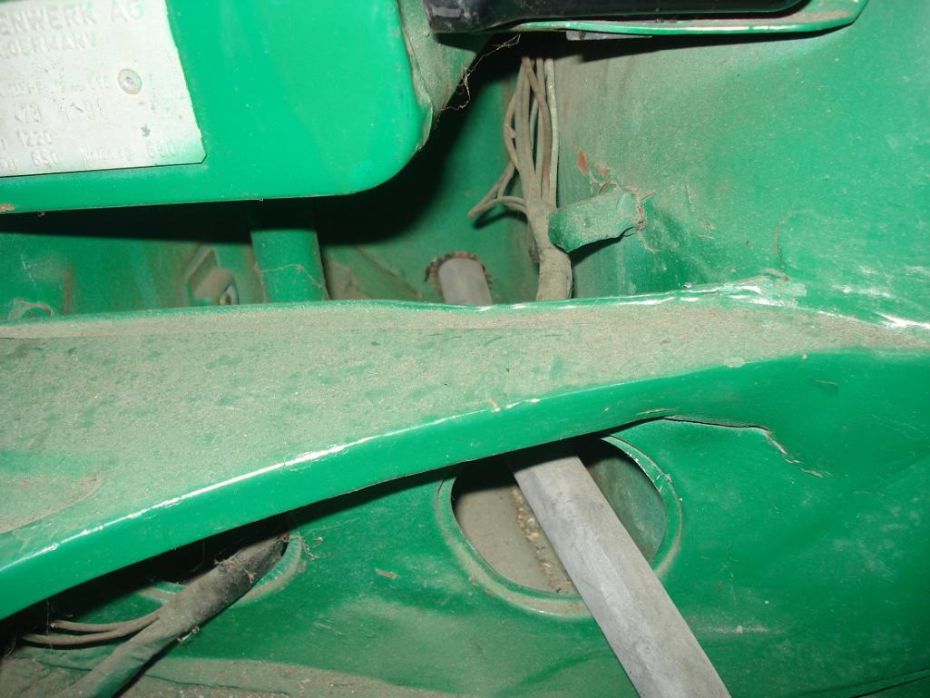
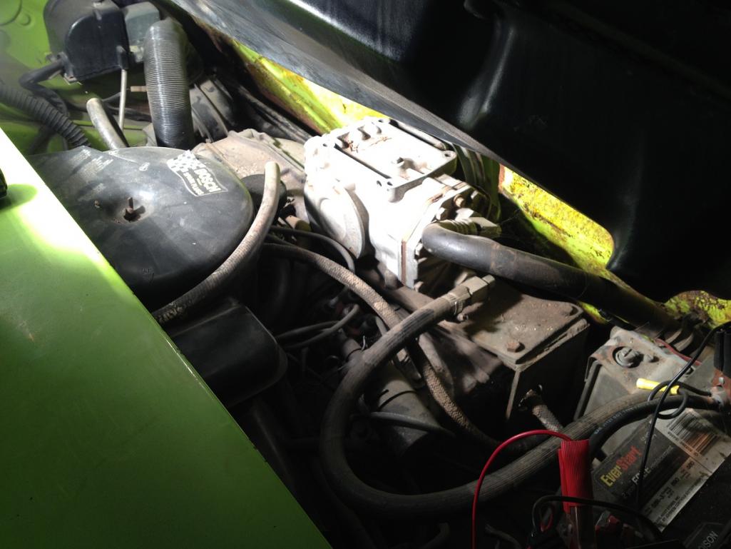
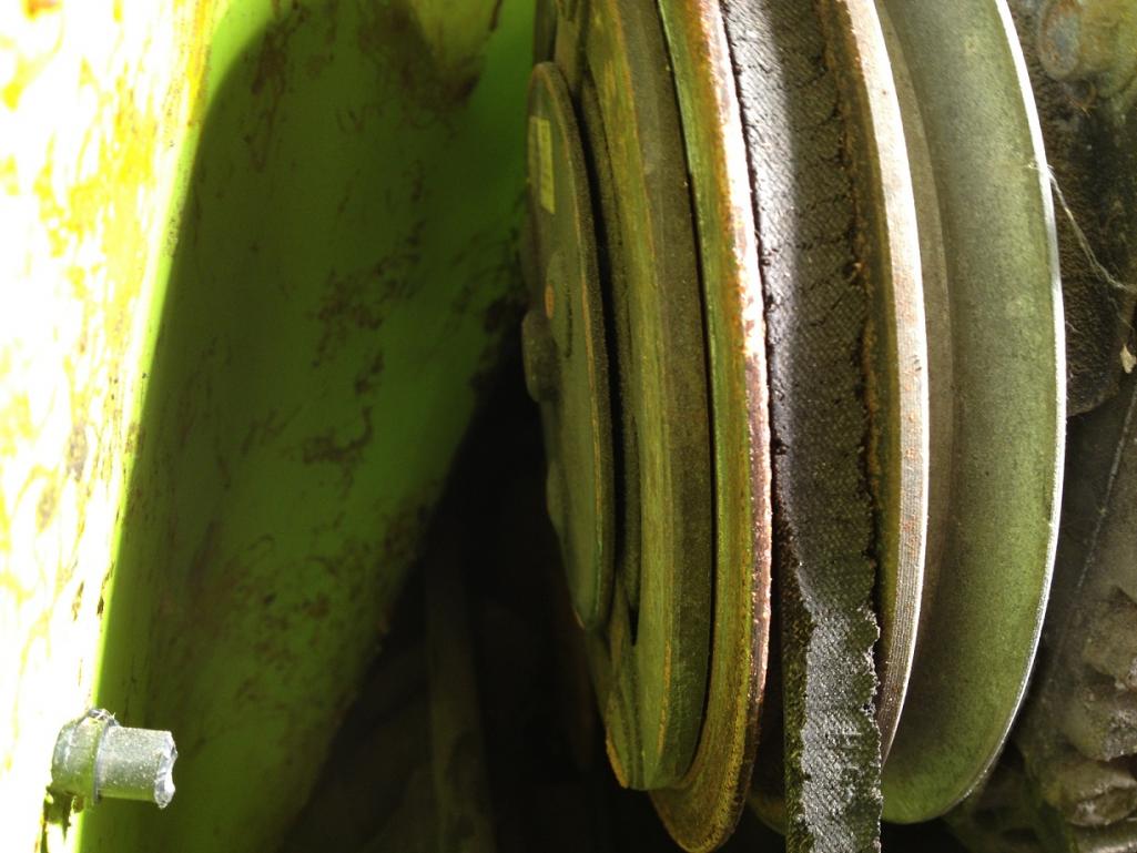
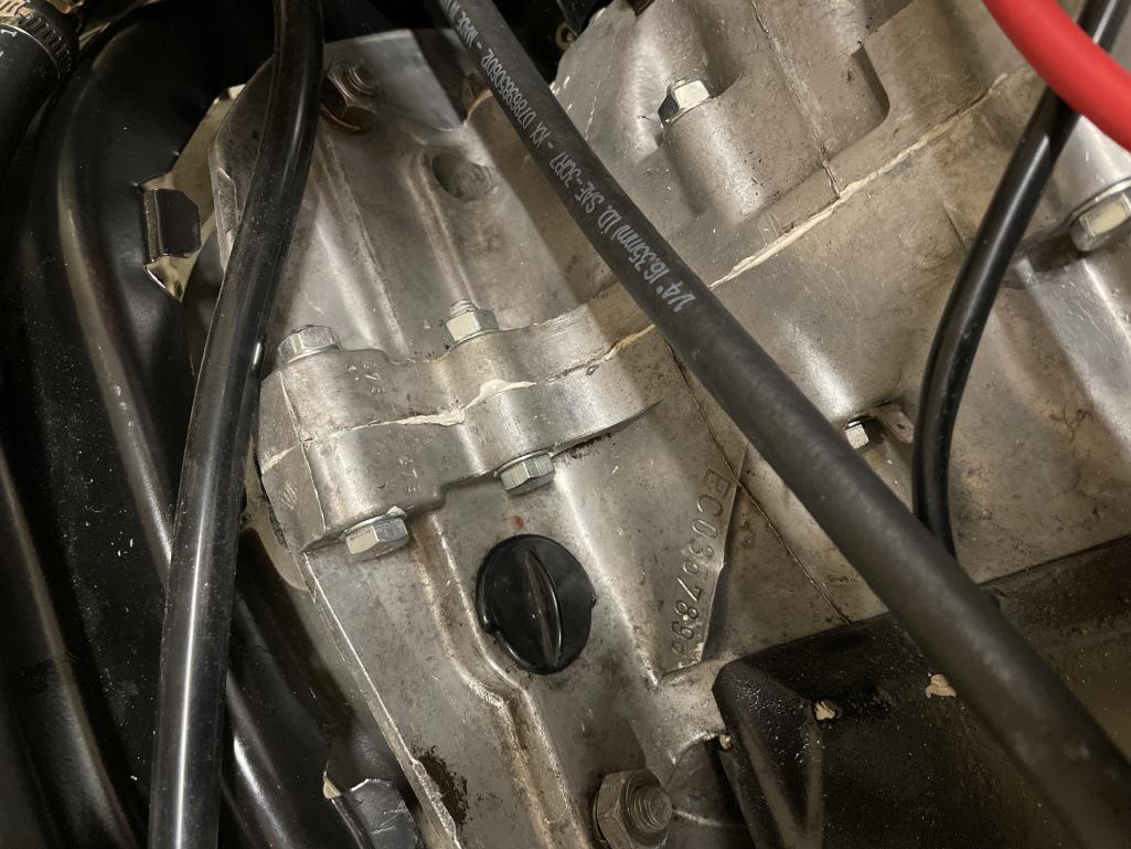
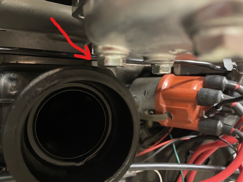
K guys, I wanted to dig in a little more on this because honestly I have always been curious about the AC in this car myself. I am planning on dropping the engine in this one for the first time so I started work on getting the AC stuff out of the way at least. Car is winning though... Without much documentation on this setup, I can't research the proper way to unmount it. At first I was attempting to take the entire thing out (compressor+bracket) in one piece and we found that it is still swiveling on a bolt directly underneath the compressor mount (you can see it in the pic). It appears this has been broken by a P.O., but I can almost forgive them because I can tell why it's broken. Absolutely no way to get any kind of tool on it.. tried everything!!!!
So then we tried unmounting the compressor from the base plate and got 3 of the 4 bolts off, but there's one near the firewall directly behind one of the pulleys that seems impossible to get at as well... no combination of wrenches or sockets seemed to help...
So I gave up and told Dad I'd be consulting the experts 
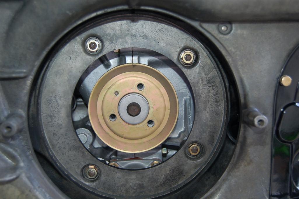
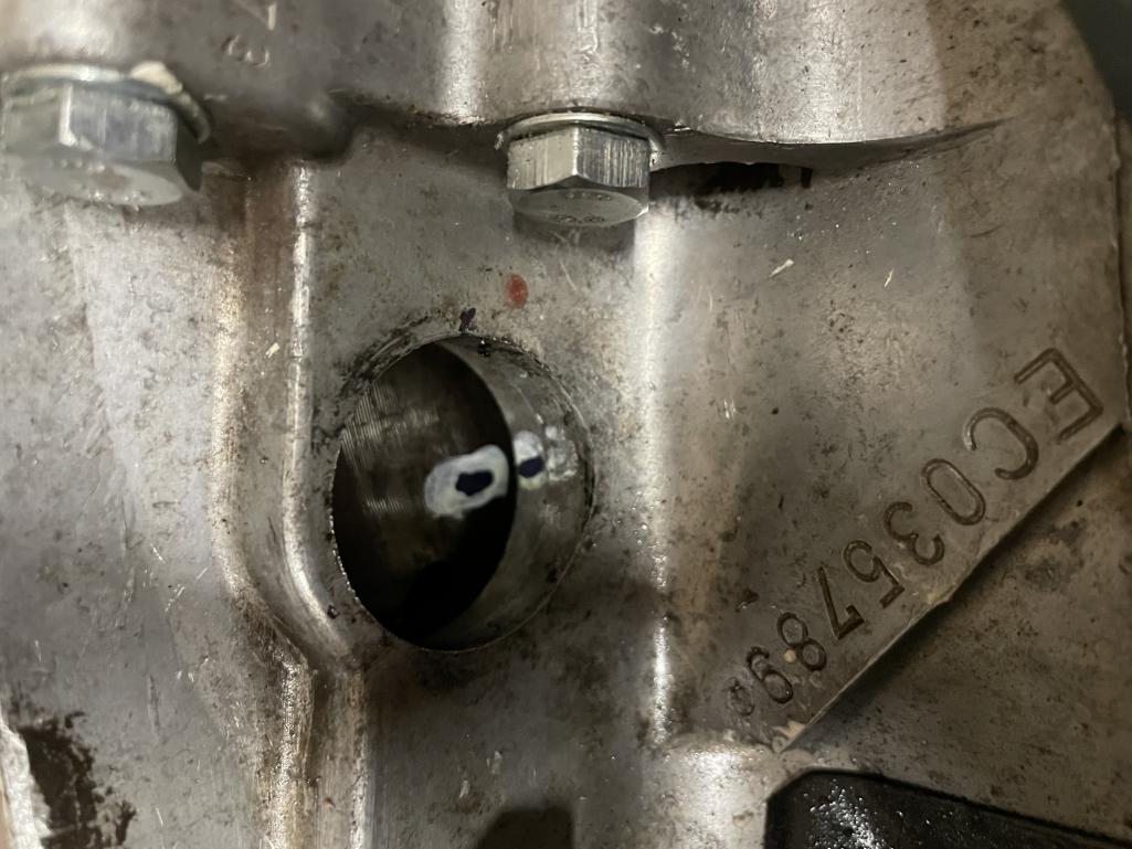
Took a pic of the bolt underneath that I can't get a wrench/socket on (seems to be a 14mm). Found some other markings on it and took some pics. I'll post in a few. There's still some original stickers and other markings on the very front but can't get a camera between the pulley and the firewall yet. Stay tuned!
The yellow arrows are pointing at the last bolt that seem to be holding the whole thing to the engine... no way to get a wrench on it though!! The blue arrow is showing the broken hole on the fan housing.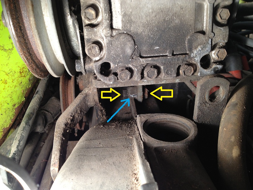
Here is closer view. The top pic is a bigger pic to give you some idea of where we're looking: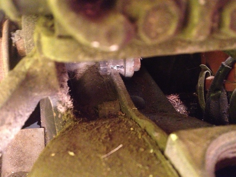
Posted by: stateofidleness Dec 16 2012, 07:49 PM
Couple more... left them a little bigger because it's hard to find large reference images for stuff like this: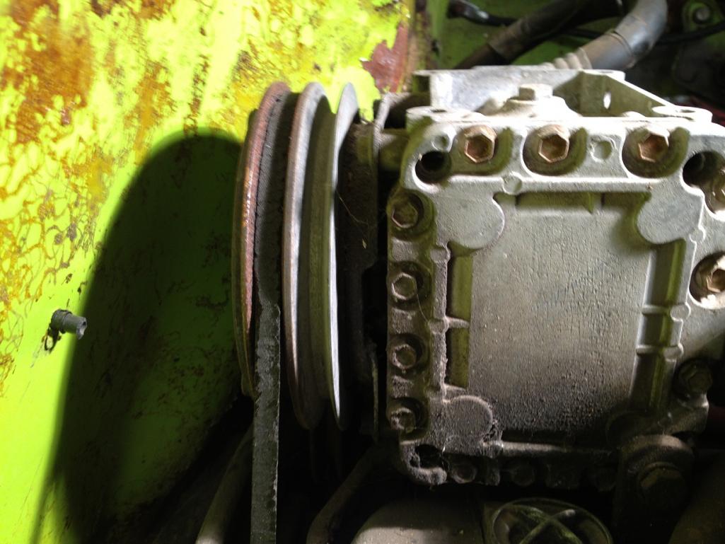
Posted by: stateofidleness Dec 16 2012, 07:51 PM
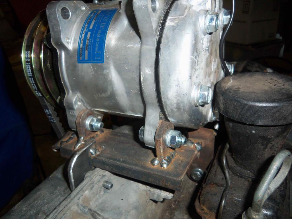
Uno Mas. Markings on the visible side of the compressor (opposite the pulley):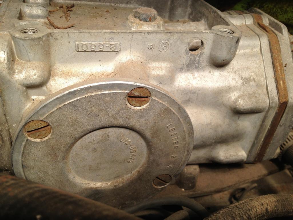
Posted by: stateofidleness Dec 28 2012, 03:35 PM
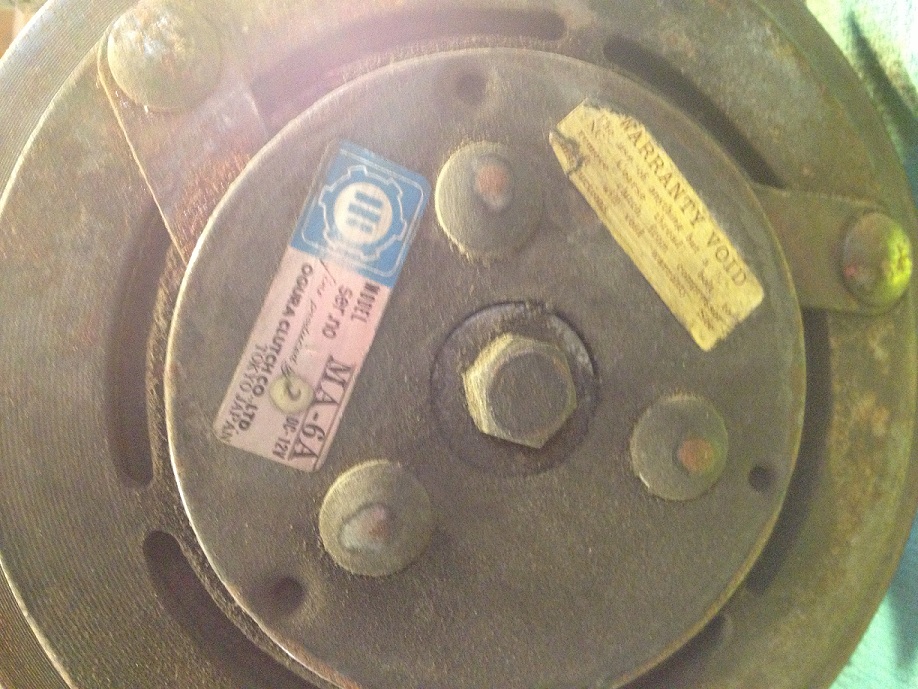
Couple more reference pics as I finished getting the compressor unmounted this week.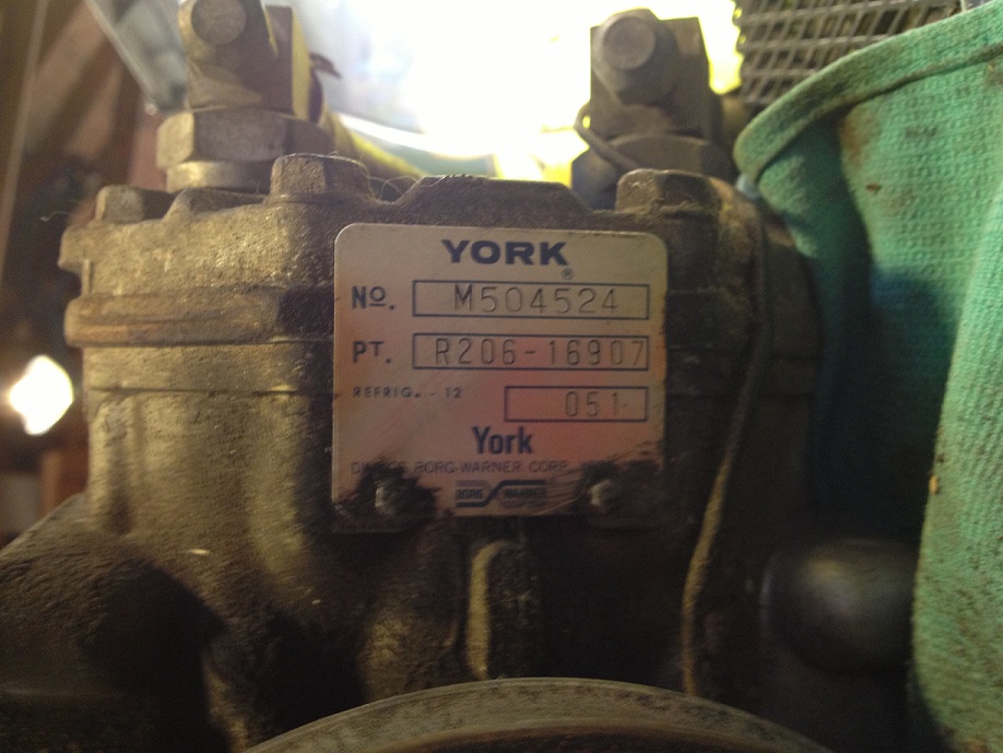
Posted by: dlee6204 Jan 24 2013, 07:48 PM
stateofidleness, Did you ever figure out how your compressor was driven off the front of the engine?
Posted by: dlee6204 Jan 24 2013, 07:51 PM
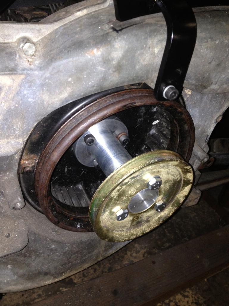
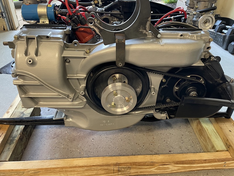
Not a big update but I did finish the pulley adapter. Now I just need to install everything one of these days and start testing it. 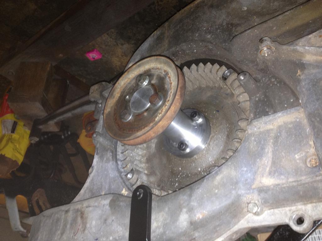
Posted by: dlee6204 May 29 2013, 08:00 AM
Version 2.0 is now up an running. I put a new motor in my car so I was waiting on that to try out the new stuff. Everything went together smoothly and so far no issues. I need to finish charging my system and then it will be smooth sailing just in time for the summer heat. 
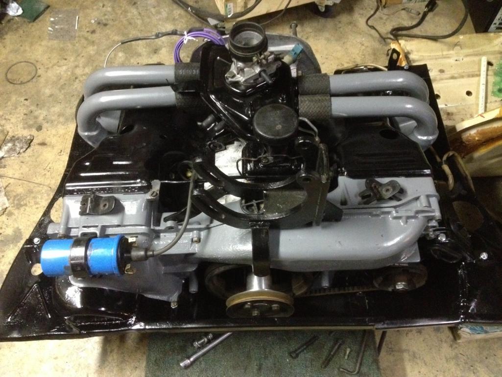
In order for the compressor to mount far enough back, I relocated the oil filler. I only needed to move it less than an inch but I went ahead and mounted it up higher. I like it better this way. 
And for those who don't know I run CIS on my car so that's why it looks a bit different. 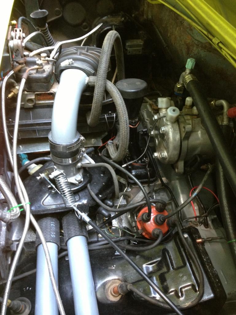
And the most exciting video to date...
https://www.youtube.com/watch?v=4LRnNZTDaTs
Posted by: dlee6204 May 29 2013, 09:28 AM
Oh and for those wondering, to set the timing I used the back of the flywheel and the small access hole. Its actually a lot easier to see the marks this way than having to stretch your body across the top of the engine.
Posted by: dlee6204 Jun 1 2013, 02:35 PM
Now for some boring stuff...
I thought I would give an update on some of my results. The other day I did and initial charge on the system and had the following results:
Ambient Temp: 75 Fahrenheit
Low Pressure: 40 psi
High Pressure:250 psi
Evaporator (Air Vent) Temp: 58 Fahrenheit
Here is one reference I use for the range of temperatures/pressures...
http://www.ackits.com/aacf/ptchart.cfm
From the initial test my numbers were a little high. From experience I knew the likely culprit was inadequate airflow over the condenser. Last year the squirrel cage fan in the condenser box froze up so I replaced it with a small electric radiator fan and I wasn't too happy with the way I mounted it and obviously that method didn't work too well so I reconfigured it today. Sorry, no pictures  I mounted the fan on the underside of the condenser so that it pulls air. Worked great. My new readings are:
Ambient Temp: 82 Fahrenheit
Low Pressure: 33 psi
High Pressure:230 psi
Evaporator (Air Vent) Temp : 54 Fahrenheit
That's a temperature drop of 28 degrees! Not too bad. Now I need to go test drive it and see how low it goes. 
Posted by: FourBlades Jun 1 2013, 06:02 PM
Nice work!
I am sure a lot of people would like a working AC in their cars.
John
Posted by: dlee6204 Sep 9 2013, 07:41 PM
Just an update. I made a batch of extra adapters that I'd sell to anyone interested. Each would include the necessary hardware. Pulley not included. $85 shipped conus I apologize for the crappy pics. 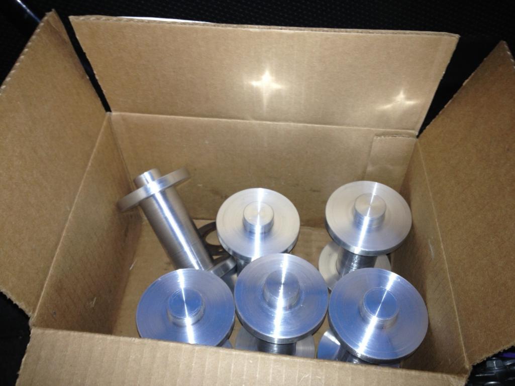
I am also putting together at least two "kits" that I'll be selling shortly which includes the drive pulley, compressor, mount, hardware and everything necessary to mount a compressor on top of the motor. Stayed tuned for that.
Posted by: timothy_nd28 Sep 9 2013, 07:43 PM
I'll take an adapter!
Nice work 
Posted by: dlee6204 Oct 21 2013, 10:45 AM
BUMP
http://www.914world.com/bbs2/index.php?showtopic=222941
Posted by: rsrguy3 Mar 1 2014, 05:42 AM
Aside from selling kits what was the conclusion? Does it keep you totally frosty in the heat? Whats the hottest exterior temp you've run in and did it keep up?-Guy
Posted by: dlee6204 Mar 1 2014, 06:59 AM
This system will keep you cool even on a hot day. Currently the system I am running is merely a "stock" system with an upgraded compressor and R134. Switching to r134 definitely puts a limit on the system. I'm envious of those that get super cold temps with r12. I'll be working to improve my system this season and do some more research to see what can be done to get temps down even further. I'll probably start by replacing my condenser with an improved version. I'll of course keep keep this thread alive with new developments.
Posted by: HalfMoon Mar 3 2014, 06:01 PM
Terrific and very informative thread. I'm very seriously considering the AC conversion for my v-8 914 from Renegade. I've spoken with them several times about it.
A few things I wonder about the Renegade conversion (that they weren't really able to anwser)
Not sure about the condensor they provide but pretty sure it's at least a serpintine type. They really couldn't say if it was a serpentine or a parraelel (optimuim).
Also, the bractery they've developed is for a compressor called a "Velero". Sadly they didn't know the model number off hand (but hopefully they will when I call back).
Lastly, they have several evap units. Under dash (see pic) with a heater core. Also a new system that mounts in the cowl (no pix availble from me right now but soon as they send it to me, I'll post it). The cowl unit would give an easier ablity to create a defroster which could be very useful where I live as we have high humidity. And of course has the advantage of being hidden away.
My main ponder is this "Valero" compressor. Never heard of that and don't know any spec on it...
Price-about 2k without hoses or fittings.
Addedum-Correction. Compressor is known as a "Valeo"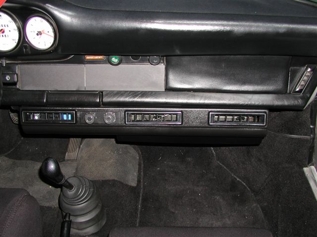
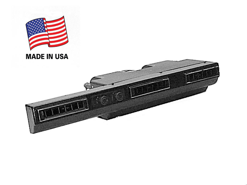
Posted by: HalfMoon Mar 3 2014, 06:59 PM
Here's a few images Steve from Renegade just sent me of the under cowl evap (with a heater core) system they now offer and a shot of the Valeo (model still unknown) compressor.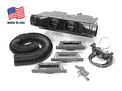
Posted by: 3d914 Mar 7 2014, 11:54 AM
This system will keep you cool even on a hot day. Currently the system I am running is merely a "stock" system with an upgraded compressor and R134. Switching to r134 definitely puts a limit on the system. I'm envious of those that get super cold temps with r12. I'll be working to improve my system this season and do some more research to see what can be done to get temps down even further. I'll probably start by replacing my condenser with an improved version. I'll of course keep keep this thread alive with new developments.
Doug, I refurbished the stock system in my 2.0L years back with a Sanden. The schematic you posted was one I created for that system. The biggest aid I found to help the A/C work better in Phoenix was a cockpit cover. Had a custom one made with a cloth-backed vinyl that covered all glass and the engine lid. Made a huge difference in A/C performance since it wasn't an oven to start with and the A/C could keep up.
Great job on the thread. Keep us up to date on changes.
Posted by: terryth Mar 25 2017, 05:23 PM
Good thread. I am embarking on my own AC install project on my 914 project. AC is about the only way I'll be able to get my wife and daughters to ride in the car in the summer. I have a new left over kit for a 70 Torino that I traded before off getting around to installing it with a sanden 508 compressor and under dash unit. My 74 914 has a 2.0 bus engine in it with a dual carb set up. My idea so far is mounting the compressor on top of the engine on the left drivers side and driving it with a double pulley mounted on the alternator and fabricating the bracket using the mounting base and adjustment mechanism from the ford 351 bracket I already have.
Posted by: DRPHIL914 Nov 6 2018, 08:11 AM
just check into this since you have the link on your signature, wondering if you ever got your box hooked up and working ?
Posted by: Literati914 Nov 9 2018, 06:24 PM
Interested in thoughts on which, (if either) might be more efficient or let's say - which might steal less power from the engine : the pulley adapters attached to the center of the fan OR a two-row Alternator pulley (one used to power the AC compressor) ? The alternator pulley seems easier but  . Pros / cons / thoughts ?
Posted by: Chris914n6 Nov 9 2018, 11:53 PM
Interested in thoughts on which, (if either) might be more efficient or let's say - which might steal less power from the engine : the pulley adapters attached to the center of the fan OR a two-row Alternator pulley (one used to power the AC compressor) ? The alternator pulley seems easier but
. Pros / cons / thoughts ?Comp off the Alt pulley will add that load stress to the Alt belt.
I've worked on other cars with both -- Comp on a separate belt and pulley, and same belt with the Alt. Also the Serpentine system with it all connected. If it's easier for you to do try it.
Posted by: friethmiller Apr 29 2021, 02:48 PM
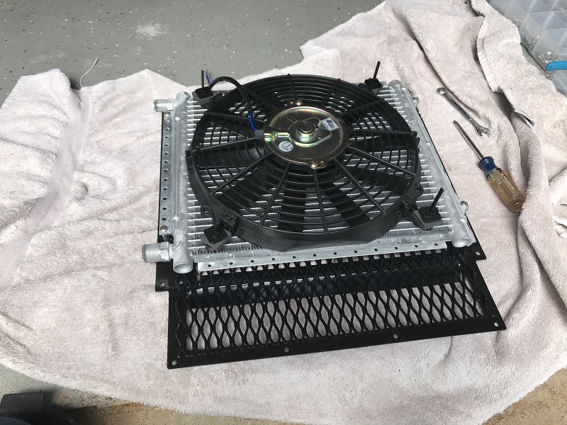
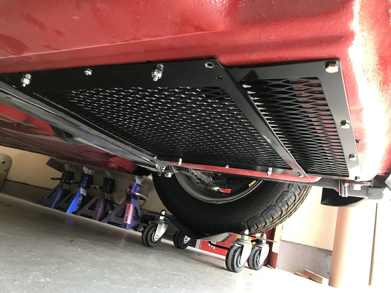
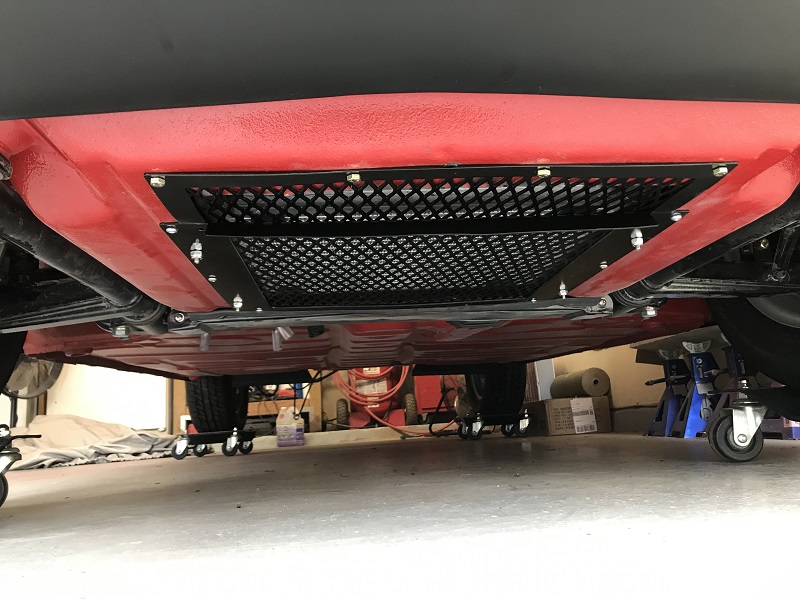
Condenser Install I think I mistakenly placed my previous photos on Doug's other commercial A/C thread. Go there to see my pre-fit photos. So, here we go! Here are my final install pics of my A/C Condenser unit on my '74. I had to make a last minute adjustment to the flipped down portion of the mounting cover (photos 2 and 3). My issue was that it just stuck down too low. If I hit a speed bump or something, the entire condenser would be ripped out of my trunk. I also wanted something to cover up the front portion of the grate. I satisfied both issues by pounding the metal bracket flat and then cutting out an inner rectangle - leaving enough to bend down a much smaller scoop.
Attached thumbnail(s)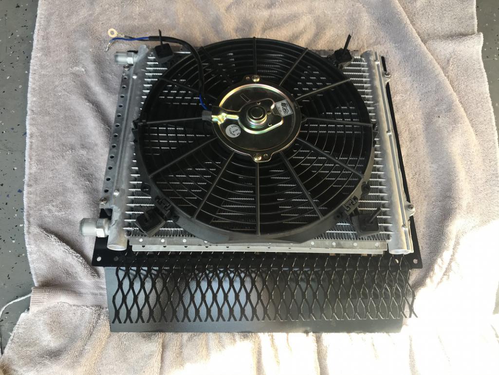
Attached image(s)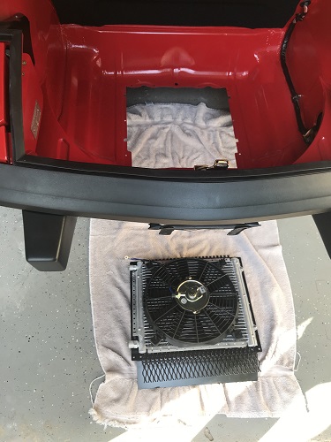
Posted by: DRPHIL914 Apr 30 2021, 12:06 PM
Condenser Install I think I mistakenly placed my previous photos on Doug's other commercial A/C thread. Go there to see my pre-fit photos. So, here we go! Here are my final install pics of my A/C Condenser unit on my '74. I had to make a last minute adjustment to the flipped down portion of the mounting cover (photos 2 and 3). My issue was that it just stuck down too low. If I hit a speed bump or something, the entire condenser would be ripped out of my trunk. I also wanted something to cover up the front portion of the grate. I satisfied both issues by pounding the metal bracket flat and then cutting out an inner rectangle - leaving enough to bend down a much smaller scoop.
thats pretty cool, nice clean install. are you using the electric compressor set up?
Phil
Posted by: DRPHIL914 Apr 30 2021, 12:07 PM
Condenser Install I think I mistakenly placed my previous photos on Doug's other commercial A/C thread. Go there to see my pre-fit photos. So, here we go! Here are my final install pics of my A/C Condenser unit on my '74. I had to make a last minute adjustment to the flipped down portion of the mounting cover (photos 2 and 3). My issue was that it just stuck down too low. If I hit a speed bump or something, the entire condenser would be ripped out of my trunk. I also wanted something to cover up the front portion of the grate. I satisfied both issues by pounding the metal bracket flat and then cutting out an inner rectangle - leaving enough to bend down a much smaller scoop.
thats pretty cool, nice clean install. are you using the electric compressor set up?
Phil
Posted by: Chris914n6 Apr 30 2021, 03:35 PM
Condenser Install I think I mistakenly placed my previous photos on Doug's other commercial A/C thread. Go there to see my pre-fit photos. So, here we go! Here are my final install pics of my A/C Condenser unit on my '74. I had to make a last minute adjustment to the flipped down portion of the mounting cover (photos 2 and 3). My issue was that it just stuck down too low. If I hit a speed bump or something, the entire condenser would be ripped out of my trunk. I also wanted something to cover up the front portion of the grate. I satisfied both issues by pounding the metal bracket flat and then cutting out an inner rectangle - leaving enough to bend down a much smaller scoop.
I assume you're using a pusher fan.
Bend the flap straight down and use it as a lip to attach a flexible rubber/plastic dam (something cheap from HD that can be replaced as needed). That little 1" or so isn't going to do anything but 3-4" will. You need to create high pressure in front and low behind to get good circulation thru.
Looks great.
Posted by: friethmiller May 3 2021, 08:43 AM
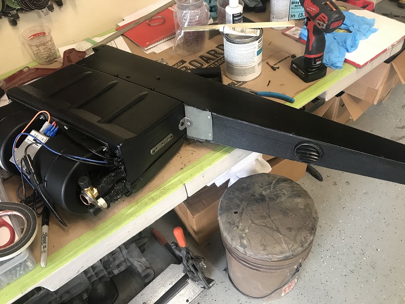
Thanks! Good comments here. I like the idea of extending the scoop with something less rigid. I have a Sanden 508 compressor that will be getting top mounted on the engine in the coming weeks. These parts all come with the A/C kit from Classic Auto Air. Photo of the dryer installed. Had to switch over to install the fuel pump and a few other items to move the engine along. More to come...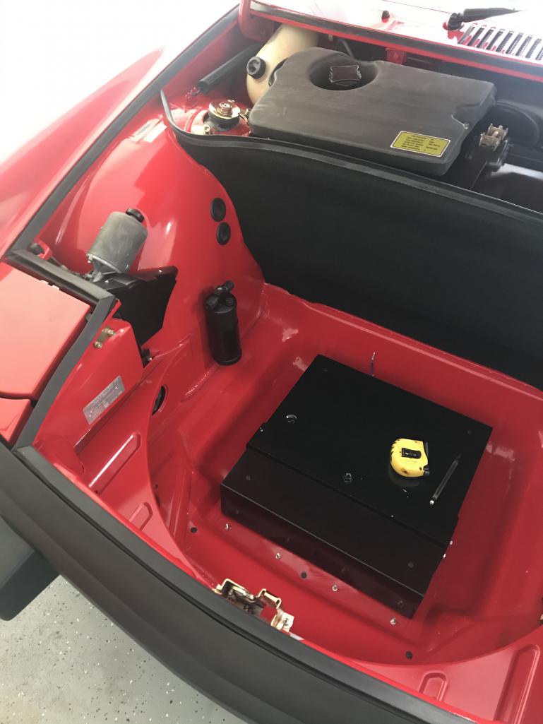
Posted by: friethmiller Jul 27 2021, 10:04 AM
Starting the A/C Compressor Install. Hired a young man with a lathe to machine out a pulley spacer based on Doug's specs. Had to buy 8mm longer Allen head bolts (m8x1.25x50) to reinstall the fan with the spacer. Working on positioning the compressor mount prior to welding the feet in place. I plan on tacking the remaining legs on and then removing for a final welds. My concern right now is the clearance at the top for the compressor with the firewall. Might move the compressor/mount back toward the oil filler a little more. Maybe Doug or others can give their 2 cents before I start welding. I might have that first leg (driver side) mounted on the wrong side of the fan housing. Also, I'm curious as to the best orientation of the compressor. Is it better to have the connections on top? Or, pointing to the passenger side?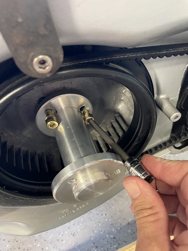
Posted by: 914sgofast2 Jul 27 2021, 11:46 AM
Starting the A/C Compressor Install. Hired a young man with a lathe to machine out a pulley spacer based on Doug's specs. Had to buy 8mm longer Allen head bolts (m8x1.25x50) to reinstall the fan with the spacer. Working on positioning the compressor mount prior to welding the feet in place. I plan on tacking the remaining legs on and then removing for a final welds. My concern right now is the clearance at the top for the compressor with the firewall. Might move the compressor/mount back toward the oil filler a little more. Maybe Doug or others can give their 2 cents before I start welding. I might have that first leg (driver side) mounted on the wrong side of the fan housing. Also, I'm curious as to the best orientation of the compressor. Is it better to have the connections on top? Or, pointing to the passenger side?
How will you set or check the engine timing with the AC compressor mounted above the timing port in the fan housing?
Posted by: Shivers Jul 27 2021, 11:59 AM
Very cool build
Posted by: dlee6204 Jul 27 2021, 02:02 PM
How will you set or check the engine timing with the AC compressor mounted above the timing port in the fan housing?
I recommend to transfer your timing marks to the back of the flywheel and you can then use the small access hole on the back of the engine to set your timing.
Posted by: dlee6204 Jul 27 2021, 02:03 PM
Nice work @http://www.914world.com/bbs2/index.php?showuser=22863 . It's nice to see it coming together and your build is top notch!
Posted by: friethmiller Jul 27 2021, 02:34 PM
Thanks Doug and Shivers! Inching closer to the day I get to drive this car. It's been 3 1/2 years of restoration work and I've never driven a 914. I'm taking my time trying to get things in place and learning as I go. Here's where that engine is going 
Posted by: friethmiller Jul 27 2021, 08:52 PM
How will you set or check the engine timing with the AC compressor mounted above the timing port in the fan housing?
I recommend to transfer your timing marks to the back of the flywheel and you can then use the small access hole on the back of the engine to set your timing.
Doug, Do you mean the hike with the black plastic plug located on the passenger side at the rear of the case? Or, the smaller hole on the other side?
Posted by: dlee6204 Jul 28 2021, 03:49 AM
This one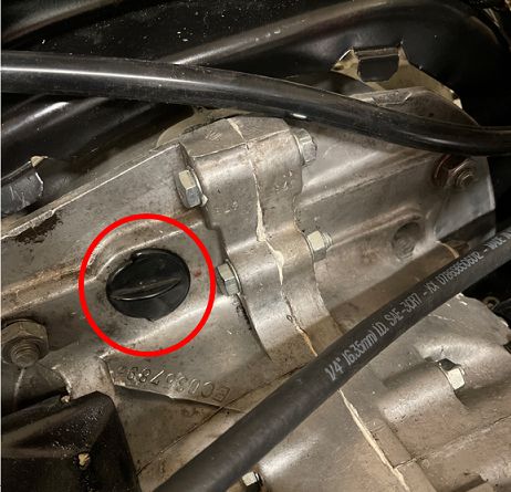
Posted by: Warren914 Jul 28 2021, 05:38 AM
I'm having AC installed this summer as part of engine/transmission rebuild with Mark Henry. Really looking forward to having the car back. Plan is to build a GT deck lid and install a 12x24 condenser underneath. Two 11-inch puller fans will be used. One fan comes on with the compressor and the other is controlled by the trinary switch or switch in the cab. I've built up a simple diode matrix with color coded wires to simplify installation. A Sanden SD7H13 compressor, engine mount, pulley and belt have been supplied by Gilmore Enterprises. Under dash evaporator, condenser coil, hoses, dryer come from Vintage Air.
I saw pictures of used dryer/receivers in the older messages in the thread. From my discussion with HVAC techs, those should never be reused. It has a limited capacity for moisture removal. If the refrigerant is replaced due to maintenance or a leak the dryer should be replaced.
Has anyone had an issue with electrical overload with the AC system? VintageAir claims the under dash evaporator may need up to about 25A for the blower and compressor clutch. The condenser fans could require about 9A each. That's up to 43A total. Maybe I'll be looking at an upgraded alternator next summer.
Posted by: Mark Henry Jul 28 2021, 07:18 AM
I'm having AC installed this summer as part of engine/transmission rebuild with Mark Henry. Really looking forward to having the car back. Plan is to build a GT deck lid and install a 12x24 condenser underneath. Two 11-inch puller fans will be used. One fan comes on with the compressor and the other is controlled by the trinary switch or switch in the cab. I've built up a simple diode matrix with color coded wires to simplify installation. A Sanden SD7H13 compressor, engine mount, pulley and belt have been supplied by Gilmore Enterprises. Under dash evaporator, condenser coil, hoses, dryer come from Vintage Air.
I saw pictures of used dryer/receivers in the older messages in the thread. From my discussion with HVAC techs, those should never be reused. It has a limited capacity for moisture removal. If the refrigerant is replaced due to maintenance or a leak the dryer should be replaced.
Has anyone had an issue with electrical overload with the AC system? VintageAir claims the under dash evaporator may need up to about 25A for the blower and compressor clutch. The condenser fans could require about 9A each. That's up to 43A total. Maybe I'll be looking at an upgraded alternator next summer.
Usually those will be start up loads, actual running loads will likely be less, Warren with your huge Optima yellow top battery those start up loads hopefully won't be an issue. I'm planing to run a 10+ gauge wire direct from the battery to up under the dash for the head unit.
Posted by: Warren914 Jul 28 2021, 07:37 AM
Hope you're taking photos!
I have a bunch of wire, connectors, etc to ship to you with the diode block.
Usually those will be start up loads, actual running loads will likely be less, Warren with your huge Optima yellow top battery those start up loads hopefully won't be an issue. I'm planing to run a 10+ gauge wire direct from the battery to up under the dash for the head unit.
Posted by: friethmiller Jul 28 2021, 09:55 AM
Sounds like a cool build Warren914. Maybe you and/or MH can share some pics.
Posted by: Warren914 Jul 28 2021, 10:13 AM
I don't feel it's my place to post photos of Mark's garage. I'll leave it to him to post those. Here's my hand drawing for the wiring. The diode block has six diodes to switch relays and shunt reverse spikes to ground. Six wires exit the sealed heat shrink module.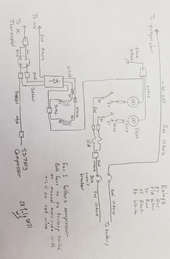
Posted by: bandjoey Jul 28 2021, 06:42 PM
I don't feel it's my place to post photos of Mark's garage. I'll leave it to him to post those. Here's my hand drawing for the wiring. The diode block has six diodes to switch relays and shunt reverse spikes to ground. Six wires exit the sealed heat shrink module.
Hi Warren..I think we're all watching these AC threads. I just saw your Facebook post on the AC install, and posted a link here. I'll go back and reroute people here.
Posted by: 76-914 Jul 28 2021, 07:45 PM
I'm having AC installed this summer as part of engine/transmission rebuild with Mark Henry. Really looking forward to having the car back. Plan is to build a GT deck lid and install a 12x24 condenser underneath. Two 11-inch puller fans will be used. One fan comes on with the compressor and the other is controlled by the trinary switch or switch in the cab. I've built up a simple diode matrix with color coded wires to simplify installation. A Sanden SD7H13 compressor, engine mount, pulley and belt have been supplied by Gilmore Enterprises. Under dash evaporator, condenser coil, hoses, dryer come from Vintage Air.
I saw pictures of used dryer/receivers in the older messages in the thread. From my discussion with HVAC techs, those should never be reused. It has a limited capacity for moisture removal. If the refrigerant is replaced due to maintenance or a leak the dryer should be replaced.
Has anyone had an issue with electrical overload with the AC system? VintageAir claims the under dash evaporator may need up to about 25A for the blower and compressor clutch. The condenser fans could require about 9A each. That's up to 43A total. Maybe I'll be looking at an upgraded alternator next summer.
Which evap unit did you purchase from Vintage Air. BTW, they're friendly and helpful should you have a question. You'll usually get someone on the phone that knows what they're talking about, which is a big plus.
Posted by: Mark Henry Jul 28 2021, 08:16 PM
Which evap unit did you purchase from Vintage Air.
Attached image(s)
Posted by: Warren914 Jul 29 2021, 12:40 AM
Tech support at VintageAir has been very good. I'm pleased with their knowlwdge and willingness to help on the phone or via email.
I asked my kids (and Mark) for opinions on the evaporator. This was the unanimous suggestion.
Heritage Under Dash System Cool Only Blk Anod Eng Turned Aluminum
https://www.vintageair.com/custom/product-pop.php?pn=674005
Which evap unit did you purchase from Vintage Air. BTW, they're friendly and helpful should you have a question. You'll usually get someone on the phone that knows what they're talking about, which is a big plus.
Posted by: friethmiller Jul 29 2021, 09:40 AM
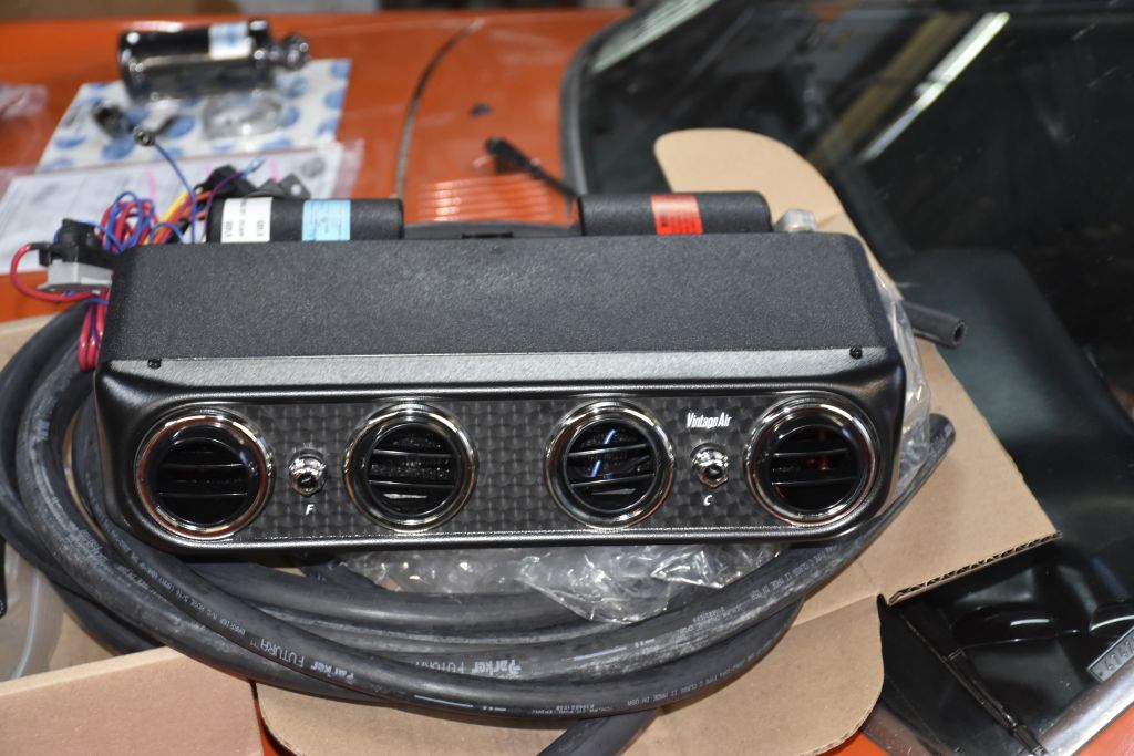
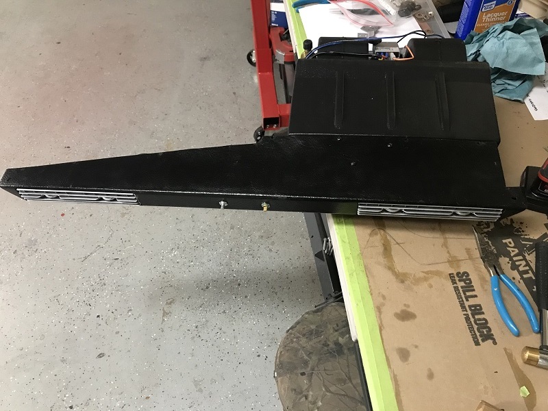
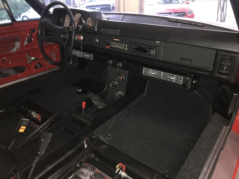
I actually did not care for the evaporate unit that came in the kit from Classic Auto Air. It was the wrong color and too big to fit between the dash and my original A/C center console. Moreover, it wasn't the same unit that was pictured on their web site. I was a little upset since their customer service couldn't help me. In a micro-fit-of-rage, I decided to purchase a "more" original unit off eBay and use that one instead. The problem with an original unit is that it's... well... 50 years old! So, I decided to create my own Frankenstein. I restored the front end of the old unit and married it up with the new backend/evap motor. The two halves almost matched exactly. Just had to fill in a small spot in the back. My goal was to get the best of both worlds. None of the hoses or electric is hooked up yet but here are a few photos. 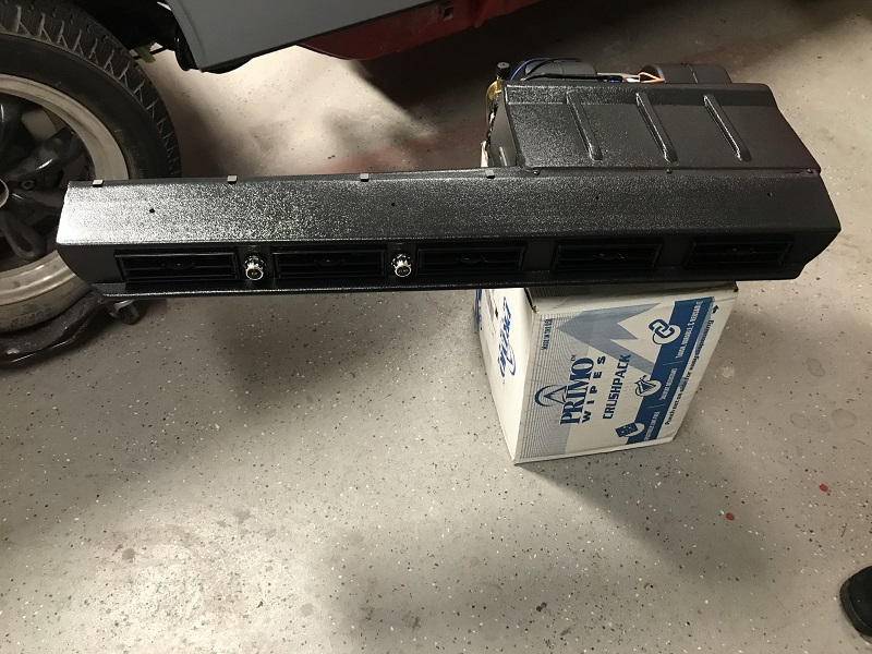
Posted by: djway Jul 29 2021, 03:50 PM
Looks good.
I rehabbed a VPC unit for my T4 powered Notchback. All I changed was to add a new style expansion valve. Blew very cold. I did discover that using the Mastercool tool to crimp the fittings to the hose requires multiple crimps at 180 deg increments to avoid leaks.
A bigger problem for me has been finding vents in good shape as they are a specific size. Yours look good.
Posted by: 76-914 Jul 29 2021, 07:10 PM
That looks great!
Posted by: 76-914 Jul 29 2021, 07:15 PM
Looks good.
I rehabbed a VPC unit for my T4 powered Notchback. All I changed was to add a new style expansion valve. Blew very cold. I did discover that using the Mastercool tool to crimp the fittings to the hose requires multiple crimps at 180 deg increments to avoid leaks.
A bigger problem for me has been finding vents in good shape as they are a specific size. Yours look good.
Same tool here. I found that going past the the indicated stop point works too.
Posted by: friethmiller Jul 29 2021, 10:15 PM
Good to know on the Master Cool Crimper. I haven’t used mine yet and will definitely keep that in mind when I do. FWIW, I still have usable vents from the front of my new unit that I don’t need. If anyone wants them, I have 5 plastic vents that are approximately 5” x 1 1/2”
Posted by: 76-914 Jul 29 2021, 10:52 PM
Good to know on the Master Cool Crimper. I haven’t used mine yet and will definitely keep that in mind when I do. FWIW, I still have usable vents from the front of my new unit that I don’t need. If anyone wants them, I have 5 plastic vents that are approximately 5” x 1 1/2”
I need a replacement vent but mine is Vintage Air. Let me measure mine tomorrow and post a pic. These companies are small and may share a manufacturer.
Posted by: djway Jul 30 2021, 10:52 PM
My vents are aprox 4 x 1.25
I always went a little past the indicator mark when crimping.
What I noticed was the ferrule didn't crimp in and kind of stuck out at where I assume was the location the jaws met. I was able to get the device back on the ferrule while in location which I mounted it to be 180deg from where I assume it was originally.
I tried the AC again after it had been sitting for a while and still seemed to blow cold so fingers crossed.
I also made a bracket and installed the throttle stop solenoid which really helps drivability.
Posted by: friethmiller Jul 31 2021, 09:21 PM
Here's the final mock-up of the A/C compressor before installing the engine. Two things I learned here. 1) Tacking the legs to the mount with the compressor installed and lined up worked very well and saved a bunch of time; 2) the oil filler tube is going to be in the way of the compressor and something will need to be modified. I know Doug extended his filler tube to accommodate the compressor. I'm going to see I can get a flat allen head bolt to provide enough clearance for the oil filler cap to screw on. The last pic shows how I tried, and failed, to get enough space from grinding down the offending compressor bolt.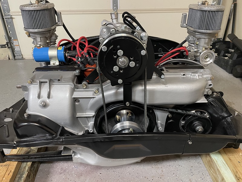
Posted by: djway Jul 31 2021, 10:37 PM
If you shorten the filler would it clear?
I used epoxy or JB weld.
Posted by: 76-914 Jul 31 2021, 11:00 PM
Does that bolt screw into a nut welded in place or a tapped opening on the bracket? If so maybe use an elevator bolt and nut one diameter smaller to pass through?
Posted by: 914sgofast2 Aug 1 2021, 08:09 AM
How are you going to set and check ignition timing with the ac compressor mounted right over the timing port?
Posted by: friethmiller Aug 1 2021, 10:47 AM
How are you going to set and check ignition timing with the ac compressor mounted right over the timing port?
As mentioned before by Doug, the timing can be set/checked with the hole at the back of the case against the fly wheel. I did that by rotating the engine to the timing mark and then painting that spot on the flywheel. You can also remove the compressor from the mount with just 4 bolts.
Posted by: friethmiller Aug 1 2021, 11:09 AM
If you shorten the filler would it clear?
I used epoxy or JB weld.
Perhaps. Could also get a inch bigger belt so the compressor would be above the cap. Going to wait and see how much room I have in the engine bay once the engine is installed.
Posted by: friethmiller Aug 1 2021, 11:15 AM
Does that bolt screw into a nut welded in place or a tapped opening on the bracket? If so maybe use an elevator bolt and nut one diameter smaller to pass through?
The offending bolt is a compressor bolt (back housing). I believe it’s an M8 with a fine 1.0 pitch. It might be hard(er) to find in a flat/low profile replacement. I’ll check with Belmetric and see what they have.
Posted by: Warren914 Aug 1 2021, 01:22 PM
Why are you mounting the compressor on top of the engine? SD7H13 and similar will mount to the side closer to the battery. I've seen photos and it looks good. Gilmore Enterprises sells the mounts!
Posted by: friethmiller Aug 1 2021, 09:01 PM
Why are you mounting the compressor on top of the engine? SD7H13 and similar will mount to the side closer to the battery. I've seen photos and it looks good. Gilmore Enterprises sells the mounts!
Because I don’t want to cut into the side of my engine bay and tin to side mount the compressor. I just spent way too much time repairing/replacing all the metal in the engine bay. It’s a better location for me. You can certainly go that route if you want.
Posted by: ChrisFoley Aug 2 2021, 04:37 AM
Why are you mounting the compressor on top of the engine? SD7H13 and similar will mount to the side closer to the battery. I've seen photos and it looks good. Gilmore Enterprises sells the mounts!
Because I don’t want to cut into the side of my engine bay and tin to side mount the compressor. I just spent way too much time repairing/replacing all the metal in the engine bay. It’s a better location for me. You can certainly go that route if you want.
An AC compressor in the stock location interferes with the HE on my header, so your choice to move it was perfect.
I did some development on a top mounted AC compressor but abandoned the project. This looks good.
Posted by: friethmiller Aug 2 2021, 07:19 AM
Wow! Glad I went this route. Thanks, Chris. All credit goes to Doug (dlee6204) who started this thread. The pulley standoff was based on his design and he went out of his way to assist me in modifying the compressor mount for my Sanden 508 compressor.
Posted by: friethmiller Aug 4 2021, 08:43 AM
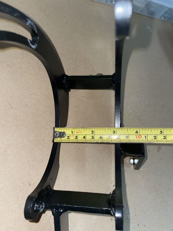
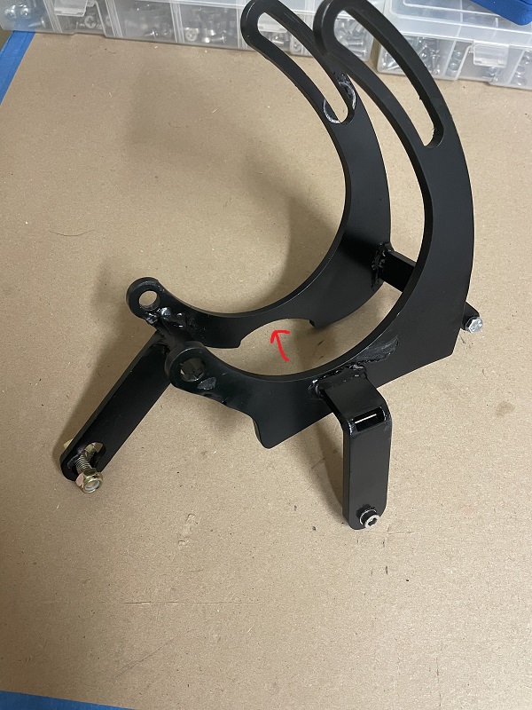
Ok, I have had a few questions about the A/C mount and how I assembled everything. Since the dimensions b/w the mount ears on the Sanden 508 is approximately 82mm (pic 1), the two side pieces between the U-shaped brackets were cut to 80mm (pic 2). These two pieces slot into the U-shaped brackets to give an overall width of 80mm (pic 3). Note, before welding these four pieces together, alignment should be checked against the blower assembly. Make sure the U-shaped bracket at the back has the relief to go over the timing hole plug (pic 4). For mounting the legs, I tacked the smallest one on first and then with the compressor on the mount on the engine, I tacked the other legs on. Keep in mind, having the compressor belt or a string mounted over the pulleys is very helpful for alignment. Removing the mount, I then finished welding the legs on the workbench. I did one more final fitment just to verify everything before priming and painting the mount. 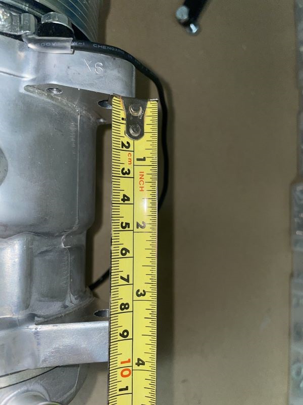
Posted by: AZBanks Aug 4 2021, 04:11 PM
I used the Gilmore mount and a Sanden sd5h11 compressor and I did not have to cut the engine shelf.
I did have to cut the rubber attached to the shelf and the engine tins.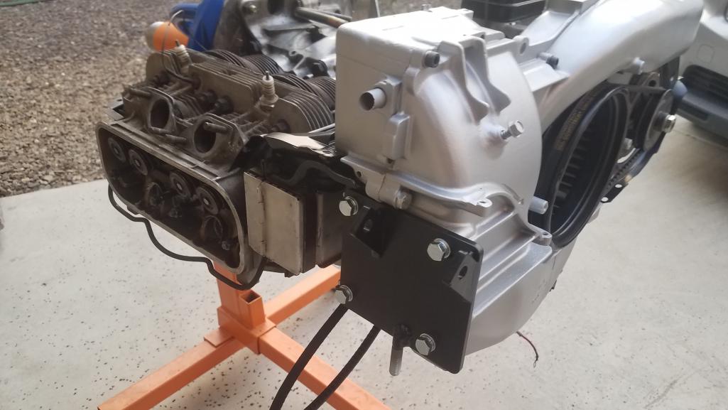
Posted by: AZBanks Aug 4 2021, 04:14 PM
I'm not trying to hijack the thread, just wanted everyone to know that you can fit some compressors on the side without cutting up the engine shelf. 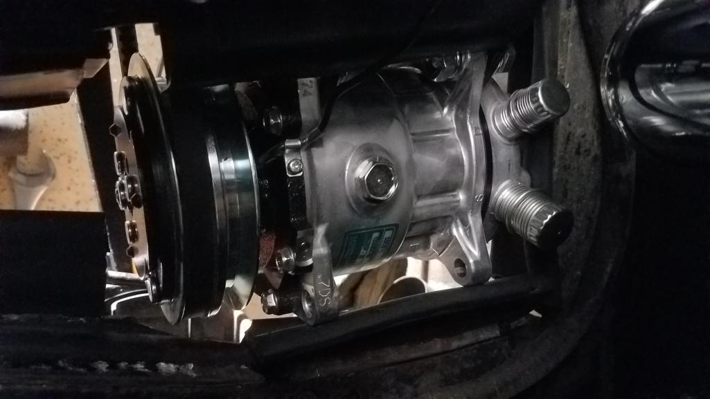
Posted by: friethmiller Aug 4 2021, 06:48 PM
@http://www.914world.com/bbs2/index.php?showuser=5245 , very cool! Good to know on the side mount. Your engine/compressor look great. Best of luck getting everything running. I know I still have a lot to do and figure out on mine.
Posted by: michelko Aug 20 2021, 02:05 AM
Hi that is a very clean setup. Can you number the diameter of the pulleys?
Regards Michael
Posted by: friethmiller Aug 23 2021, 09:06 AM
Hi that is a very clean setup. Can you number the diameter of the pulleys?
Regards Michael
Unfortunately, I cannot easily get to the pulley with the engine in the car now. I'll try and see what I can do this evening. I'm thinking the bottom (crank) pulley is about 4" (approx. 100 mm).
Posted by: friethmiller Apr 8 2022, 07:55 PM
Alright. My 914 is operational! Turning my attention to finally wiring up all my A/C components. Got to get the A/C cooling before the Texas heat set in down here. I've created a very ugly wiring diagram. Anybody see anything incorrect here? I can run the evap from either the #8 or #9 fuse (switched power) or directly from the battery. I ran a separate 10 gauge wire from the battery to the frunk for the condenser fan. Just need to connect all the wires to the components and the relay. Thanks all.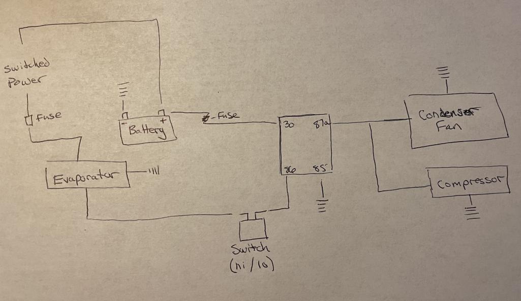
Posted by: friethmiller Apr 11 2022, 08:15 AM
![]() Looking for assistance on my wiring before I start hooking everything up. Thanks
Looking for assistance on my wiring before I start hooking everything up. Thanks
Posted by: friethmiller Apr 11 2022, 12:17 PM
![]()
Posted by: ChrisFoley Apr 13 2022, 12:24 PM
![]()
Sorry I can't answer your question Fred. It looks good to me but I don't know sh!t about AC control circuits.
Posted by: Chris914n6 Apr 13 2022, 08:23 PM
You left out the binary pressure switch. Also you want the comp to cycle on and off separate from the fans. Shouldn't be too hard to find a diagram from one of the hotrod sites. AC wiring is basic but not THAT basic.
Posted by: ClayPerrine Apr 14 2022, 04:57 AM
Alright. My 914 is operational! Turning my attention to finally wiring up all my A/C components. Got to get the A/C cooling before the Texas heat set in down here. I've created a very ugly wiring diagram. Anybody see anything incorrect here? I can run the evap from either the #8 or #9 fuse (switched power) or directly from the battery. I ran a separate 10 gauge wire from the battery to the frunk for the condenser fan. Just need to connect all the wires to the components and the relay. Thanks all.
From experience, you probably need two relays, one for the compressor, and one for the fans. If you are running fuel injection, you want to add an idle up device too. Get a tank switching valve for a Ford pickup with dual tanks. Cap the normally open side, and plumb it in parallel with the decel valve. Hook the wire up to another relay. Then once you have the car started and the AC running, you will have to add restrictions to the intake hose of the valve to lower the idle speed. I used a dowel rod the same size as the ID of the hose, and drilled out the center until I got the same idle speed as when the AC was off.
Hope that helps.
Clay
Posted by: Rider914 Apr 14 2022, 12:30 PM
From experience, you probably need two relays, one for the compressor, and one for the fans. If you are running fuel injection, you want to add an idle up device too. Get a tank switching valve for a Ford pickup with dual tanks. Cap the normally open side, and plumb it in parallel with the decel valve. Hook the wire up to another relay. Then once you have the car started and the AC running, you will have to add restrictions to the intake hose of the valve to lower the idle speed. I used a dowel rod the same size as the ID of the hose, and drilled out the center until I got the same idle speed as when the AC was off.
Hope that helps.
Clay
[/quote]
This is genius!
Posted by: friethmiller Apr 14 2022, 02:17 PM
Thanks All! Really appreciate the input. Sorry if I oversimplified the wiring. The instructions (image below) that I received in Custom Auto Air's 914 A/C kit was beyond terrible. While their phone support is good, they don't really know the 914 setup. From what I can gather, this kit was "acquired" when they merged with another company several years back. I'm just trying to figure it out the best I can. I'll see about adding a relay for the compressor. I'm running dual carbs, BTW.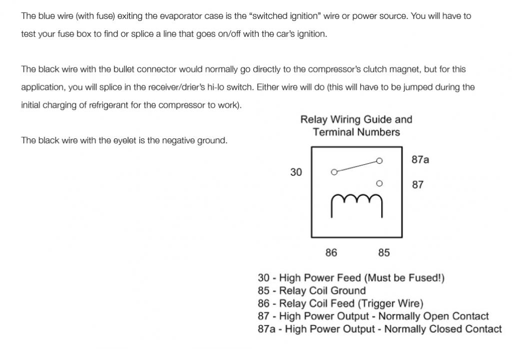
Posted by: friethmiller Apr 14 2022, 02:23 PM
Sorry I can't answer your question Fred. It looks good to me but I don't know sh!t about AC control circuits.
No worries, Chris. You've done plenty already to help my 914! Which, by the way, sounds so sweet with your custom exhaust/muffler. Get a ton of compliments on the sound of my engine.
Posted by: friethmiller Jun 3 2022, 02:50 PM
After fixing a leak, and securing a new ground for the evaporator unit, my A/C is finally operational!! I still need to tighten the compressor belt a bit more but she's blowing colld air. Not a moment too soon! It's officially summer here in TX. Shout out to Doug (the OP) and several of the others that have chimed in on this thread. Thanks y'all!!
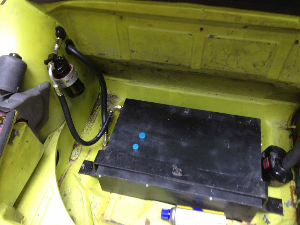
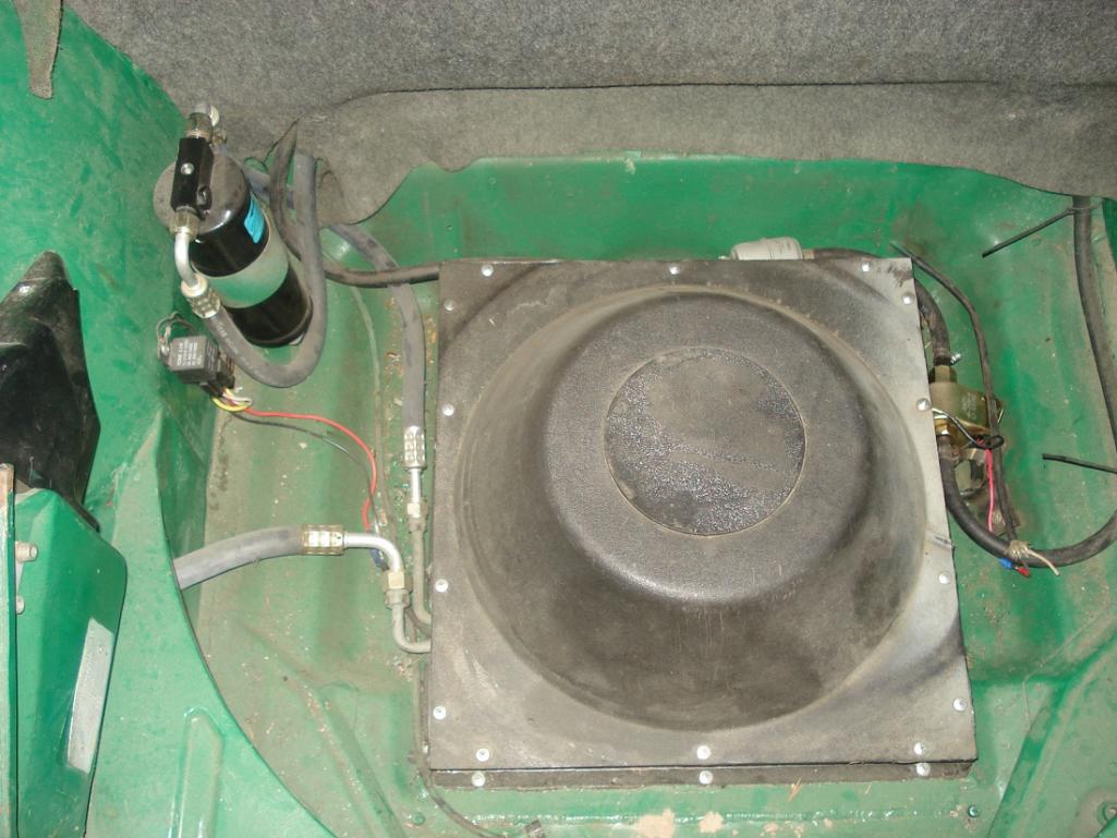
Here's a pic of the wiring in the frunk with the condenser & dryer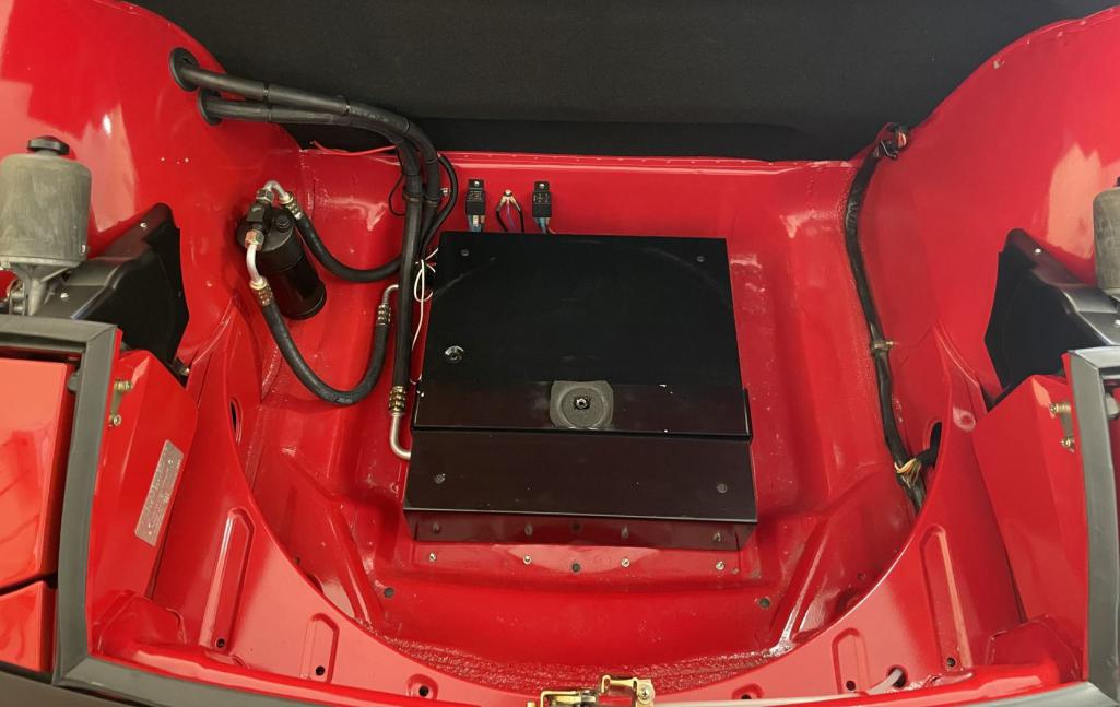
With everything buttoned up: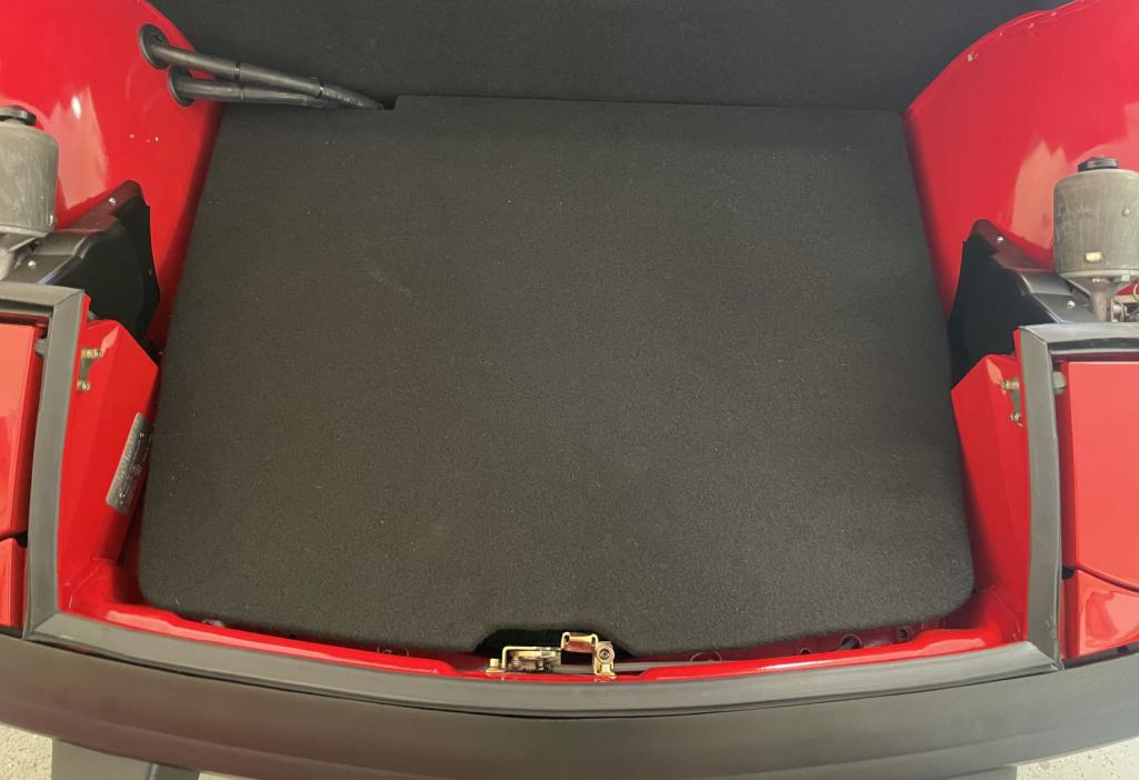
Pic of the flexible condenser intake flap (part of a door seal from Home Depot):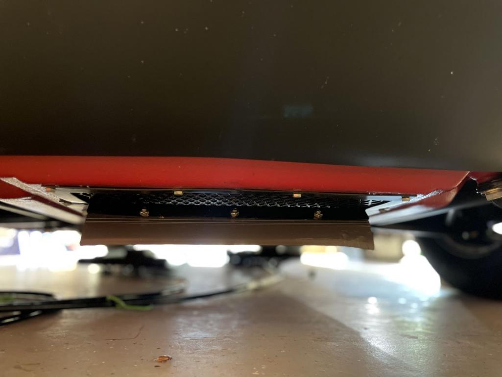
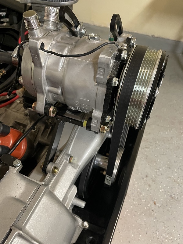
Pic of compressor with hoses - Note the 2 new 10 gauge wires on the battery for the evap and condenser.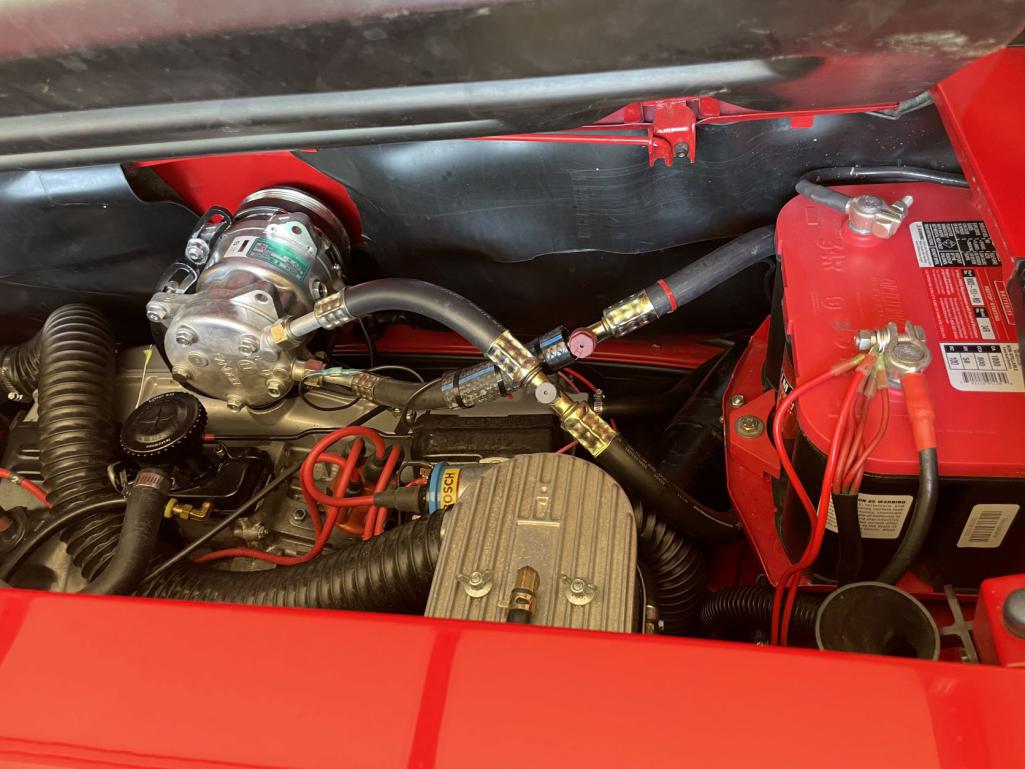
Posted by: ChrisFoley Jun 3 2022, 03:25 PM
Posted by: worn Jun 3 2022, 05:33 PM
Congratulations! Did you understand what Clay was saying about a two tank Ford? He is one of the most expert hot weather guys I can think of, but what tanks? Am I too far north?
Posted by: friethmiller Jun 3 2022, 08:55 PM
Congratulations! Did you understand what Clay was saying about a two tank Ford? He is one of the most expert hot weather guys I can think of, but what tanks? Am I too far north?
I understand and believe you but I don’t have fuel injection. Is there a different solution for carbs? The compressor pulls my idle down a little too low.
Posted by: Front yard mechanic Jun 4 2022, 06:27 AM
I really like the looks of your ac setup maybe try to fit a fast idle solenoid 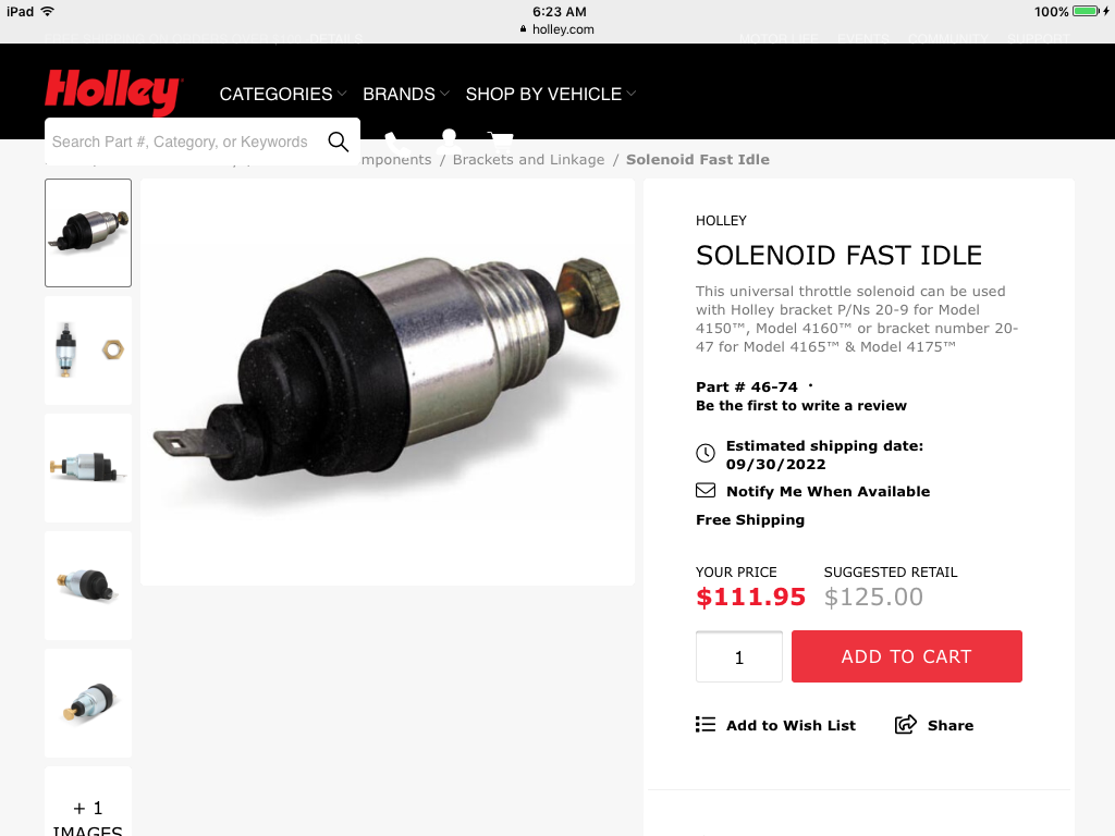
Posted by: friethmiller Jun 4 2022, 06:56 AM
thanks! Funny, I was just searching for an idle solenoid for Weber 44s. Might have to use something like this. I was also wondering if Tangerine Racing’s manual idle control might work as well.
Posted by: ChrisFoley Jun 4 2022, 03:43 PM
thanks! Funny, I was just searching for an idle solenoid for Weber 44s. Might have to use something like this. I was also wondering if Tangerine Racing’s manual idle control might work as well.
It would probably be useful for that. Although the solenoid applies pressure close to the point of need. The hand throttle applies tension to the throttle cable.
Posted by: friethmiller Jun 4 2022, 04:43 PM
thanks! Funny, I was just searching for an idle solenoid for Weber 44s. Might have to use something like this. I was also wondering if Tangerine Racing’s manual idle control might work as well.
It would probably be useful for that. Although the solenoid applies pressure close to the point of need. The hand throttle applies tension to the throttle cable.
Thanks for the info Chris. Not sure of the lead-time on this but I just ordered your hand throttle kit. I want to be able to control idle myself.
Posted by: Chris914n6 Jun 4 2022, 09:57 PM
Congratulations! Did you understand what Clay was saying about a two tank Ford? He is one of the most expert hot weather guys I can think of, but what tanks? Am I too far north?
I understand and believe you but I don’t have fuel injection. Is there a different solution for carbs? The compressor pulls my idle down a little too low.
It's called a choke. There even was an electric version in the 80s lol.
Posted by: friethmiller Jun 6 2022, 08:25 AM
Congratulations! Did you understand what Clay was saying about a two tank Ford? He is one of the most expert hot weather guys I can think of, but what tanks? Am I too far north?
I understand and believe you but I don’t have fuel injection. Is there a different solution for carbs? The compressor pulls my idle down a little too low.
It's called a choke. There even was an electric version in the 80s lol.
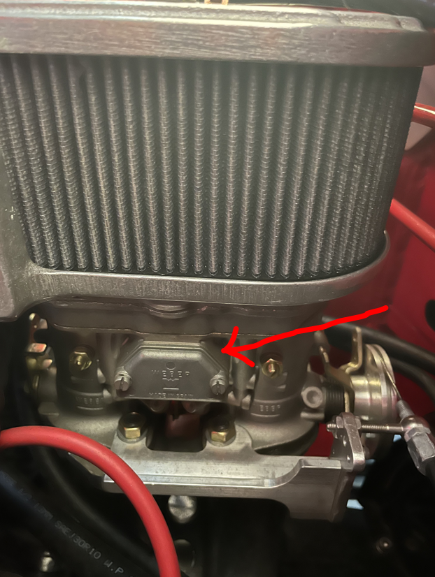
I don't think I have chokes on my 44 IDF carbs. Haven't been able to find any, manual or electric.
Attached image(s)
Posted by: ClayPerrine Jun 8 2022, 06:28 AM
Congratulations! Did you understand what Clay was saying about a two tank Ford? He is one of the most expert hot weather guys I can think of, but what tanks? Am I too far north?
I understand and believe you but I don’t have fuel injection. Is there a different solution for carbs? The compressor pulls my idle down a little too low.
It's called a choke. There even was an electric version in the 80s lol.
I don't think I have chokes on my 44 IDF carbs. Haven't been able to find any, manual or electric.
Under that cover are two pistons that can be raised up to make the mixture richer for cold running. You need the covers that have the arm and cable mount to make them work. That works fine for cold running but not for idling up for AC compressor load.
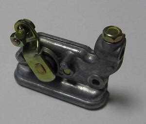
You can buy them here: https://www.dellorto.co.uk/shop/weber-carburettors-parts/carburettor-parts-weber-carburettors-parts/idf-parts/choke-actuating-mechanism/
A kicker solenoid like the one shown previously would work. I have never done one, as I don't like carbs. But you would have to fabricate a bracket to hold it in the right location to open both carbs.
Clay
Posted by: friethmiller Jun 8 2022, 09:06 AM
Congratulations! Did you understand what Clay was saying about a two tank Ford? He is one of the most expert hot weather guys I can think of, but what tanks? Am I too far north?
I understand and believe you but I don’t have fuel injection. Is there a different solution for carbs? The compressor pulls my idle down a little too low.
It's called a choke. There even was an electric version in the 80s lol.
I don't think I have chokes on my 44 IDF carbs. Haven't been able to find any, manual or electric.
Under that cover are two pistons that can be raised up to make the mixture richer for cold running. You need the covers that have the arm and cable mount to make them work. That works fine for cold running but not for idling up for AC compressor load.
You can buy them here: https://www.dellorto.co.uk/shop/weber-carburettors-parts/carburettor-parts-weber-carburettors-parts/idf-parts/choke-actuating-mechanism/
A kicker solenoid like the one shown previously would work. I have never done one, as I don't like carbs. But you would have to fabricate a bracket to hold it in the right location to open both carbs.
Clay
Clay, thanks for the info! I hear ya on the carbs
As you know, chokes aren't exactly necessary items down here in Texas. I'll look into the solenoid option. Pulling the acceleration cable slightly or something on the master carb (manual or automatic) is all I need. I'm running Tangerine's pulley system. Posted by: ClayPerrine Jun 9 2022, 05:52 AM
Congratulations! Did you understand what Clay was saying about a two tank Ford? He is one of the most expert hot weather guys I can think of, but what tanks? Am I too far north?
I understand and believe you but I don’t have fuel injection. Is there a different solution for carbs? The compressor pulls my idle down a little too low.
It's called a choke. There even was an electric version in the 80s lol.
I don't think I have chokes on my 44 IDF carbs. Haven't been able to find any, manual or electric.
Under that cover are two pistons that can be raised up to make the mixture richer for cold running. You need the covers that have the arm and cable mount to make them work. That works fine for cold running but not for idling up for AC compressor load.
You can buy them here: https://www.dellorto.co.uk/shop/weber-carburettors-parts/carburettor-parts-weber-carburettors-parts/idf-parts/choke-actuating-mechanism/
A kicker solenoid like the one shown previously would work. I have never done one, as I don't like carbs. But you would have to fabricate a bracket to hold it in the right location to open both carbs.
Clay
Clay, thanks for the info! I hear ya on the carbs
As you know, chokes aren't exactly necessary items down here in Texas. I'll look into the solenoid option. Pulling the acceleration cable slightly or something on the master carb (manual or automatic) is all I need. I'm running Tangerine's pulley system.If I were doing it, I would put it in the tunnel next to the bell crank on the pedal box. Make it push on the linkage like the hand throttle does.
Clay
Posted by: friethmiller Jun 9 2022, 12:06 PM
If I were doing it, I would put it in the tunnel next to the bell crank on the pedal box. Make it push on the linkage like the hand throttle does.
Clay
Oh! I like that idea too! Thanks.
Posted by: friethmiller Mar 25 2024, 10:39 AM
Just to follow-up on my issue from last year... I was able to install a /6-style hand throttle that I purchased from Tangerine Racing. I mainly use it for cold startups but have used it successfully to hold a minimum throttle for when my A/C is running at a traffic light on a very hot Texas day. Unfortunately, my system has a very slow leak and I plan to take it up to have @http://www.914world.com/bbs2/index.php?showuser=27135 take a look at it. Going to need cold air coming out of my vents down here soon! 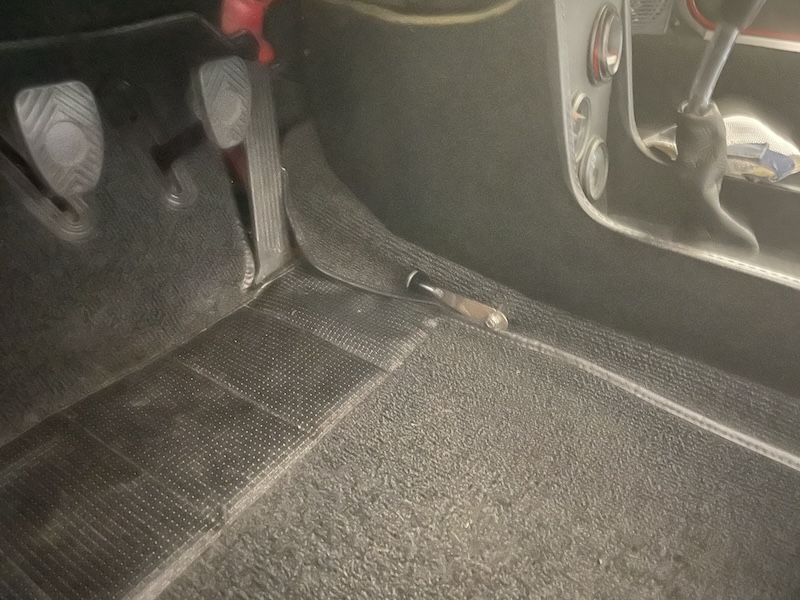
Posted by: DRPHIL914 Mar 25 2024, 10:56 AM
looking good! some day i would like to have a/c ... gets hot here in SC too, July - september are not tolerated well without AC
Posted by: technicalninja Mar 25 2024, 01:30 PM
Looking forward to your visit! 
Just quickly ran through your posts...
Goody! Goody! Flat fin multi-pass condenser, good fan, killer compressor, puppy even has a modern evap!
This is pretty much how I would do a top mount.
I'm betting that's COLD even down here when it's 100+
Once again freaking exquisite fabrication!
I have a HP10 leak detector that came with a 'reference' bottle that is a calibrated leak of R11.
You adjust the sensitivity of the detector to the reference leak...
I'm still on my first reference bottle, about 20% of an ounce has leaked out over the last 6 years. I'm on my second detector and probably the fourth sensor element...
These units can find THAT small a leak...
Was the oil died?
Did it look like green Kool-Aid? I call it Shrek blood.
If so, I have a LED UV light that will give you flash blindness if you look at it, even in sunlight.
Die leaks looks like a "fluorescent crime scene" with this light.
You've got a NICE car!
I want to play with it...
Posted by: ClayPerrine Mar 25 2024, 07:27 PM
I want one of those compressor mounts for Betty's car. I hate the idea of cutting the engine shelf in a freshly painted engine compartment. 
Posted by: friethmiller Mar 27 2024, 07:45 AM
Was the oil died?
Did it look like green Kool-Aid?
@http://www.914world.com/bbs2/index.php?showuser=27135 - I had a guy here locally that had just closed down his Automotive A/C shop during Covid charge my system. Not sure what he did to check for any leaks but I do know he had to add a ground for the evap, which I had forgot to install. Not sure if you noticed on the firewall on my LE, I created another hole just for routing A/C wiring (with the rubber plug). I learned on the red car not to wait till everything else is installed to try and wire in the entire A/C system.
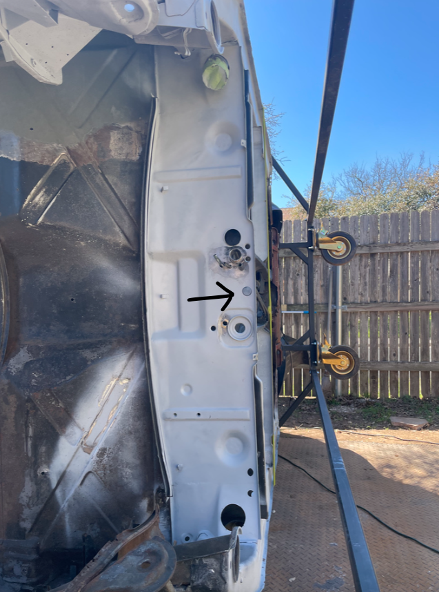
Posted by: friethmiller Apr 9 2024, 04:03 PM
Well, last Friday, I set out from Austin, TX driving 160 miles north - heading to Granbury, TX to meet Rick ( @http://www.914world.com/bbs2/index.php?showuser=27135 ) in person and let him have a look at my 914's A/C system. Rick owns Granbury Auto A/C and had kindly offered to help me out and teach me how to check/service my A/C system. With my A/C blowing warm air, I figured I'd better get up there before things started getting hot here in May. I must mention that the trip up US281 was really nice and would recommend it anytime and in any direction. As soon as I arrived in Granbury, Rick and his wife welcomed me into their shop and immediately went to work diagnosing my A/C. After fixing a few wiring snafus caused by yours truly  , Rick quickly found the leak, cleared and recharged my system, and then showed me how to check the numbers to see how my system was performing. It was interesting to see how poorly my A/C condenser and fan setup performed at idle and how things improved once I was able to move the car at speed. Rick and I discussed a few options for fixing the design of my A/C and I'm sure we has thinking about his current 914 project and how he could improve things on his car. I'm posting this here just as a prelude to some changes I have planned to my condenser/fan setup and a big "THANK YOU" to Rick and his entire family for being so kind and friendly to this complete stranger. Oh, and check out Granbury Auto AC if you need an expert who really knows what he's doing. Bravo!
Posted by: technicalninja Apr 10 2024, 08:09 AM
Fred's visit was interesting for me as well!
Awesome guy who takes DESTROYED 914s and makes them hard to tell it was destroyed.
Very nice car!
The AC system leaves MUCH to be desired...
Needs 3 times the condenser it has in it...
Needs airflow redesign for the condenser...
Needs fans that have serious CFM...
85-degree day and stopped the high side pressure was climbing through 350 with a partial charge!
I reduced the charge even more and kept highs below 325.
55 degree air at idle!
That is a delta V of 30 degrees!
Piss poor!
Running down the road we did see sub 40 air but WOW, this puppy was working HARD to achieve a delta V of 45 degrees.
"Normal" at 85 degrees is low 40s at idle and cycling a bunch at speed off of the thermo probe. Not sure how often it cycled, maybe two or three times during a 10-mile drive. A properly working system would have cycled every 90 seconds (or less) during the same drive,
I advised Fred that I WOULD NOT have allowed the system to leave the shop the way it was running had I installed it!
Possible fixes...
Change system BACK to R12. It's legal to do if the car is a 93 or earlier. This requires full system flushing. I'm not sure this would solve all issues.
Massive redesign of condenser and box. This is the "proper" fix. Dual element condenser with serious fans. I believe the fix should include a forward-facing entrance similar to a GT nose. Might be able to use a smaller opening and not have to cut bumper. Going to research fans like Tygaboy placed in Cairo's car.
The compressor mounting needs improvement as I could see it vibrating pretty seriously at any engine speed below 1500.
Idle electrical power was crappy as well. Needs charging system improvements.
Nice car, nice guy, crappy AC...
I advised NOT to run system stopped at idle. On a hot day it will bounce of the high limit switch and anything above 350 is freaking hard on the equipment.
Condenser box fabrication is in my future...
On a 105 degree day a properly designed system at speed will be bouncing off of the thermo probe and should be able to hit mid 30s for a delta V of 70!
Almost all Toyotas do this. It's possible!
I haven't tested an R12 Toyota for decades, all are R134 now-a-days.
Very best system to date. 2012 BMW X5. This has a control head that has three buttons marked "Eco", "Normal" and "Intense"
The Intense button produced 32.8 degree air at ANY speed (fan or road) including idle for 1/2 hour on a 105 degree day.
It's possible to have 134 air that is COLDER than the old R12 stuff as long as the system is designed properly...
Posted by: friethmiller Apr 10 2024, 10:23 AM
Thanks, Rick! Fixing the electrical and compressor mount issues will be easy to do and are first on my list. I'll also look at possibilities for cutting an opening in the valance just below the bumper (just the design for now). Let me know if you figure out the condenser brand/size and a matching high output fan(s). I can create an entirely new box to house it in a more upright or slant position. Sounds like fun to me Thanks!
Posted by: ClayPerrine Apr 10 2024, 11:09 AM
Fred's visit was interesting for me as well!
Awesome guy who takes DESTROYED 914s and makes them hard to tell it was destroyed.
Very nice car!
The AC system leaves MUCH to be desired...
Needs 3 times the condenser it has in it...
Needs airflow redesign for the condenser...
Needs fans that have serious CFM...
85-degree day and stopped the high side pressure was climbing through 350 with a partial charge!
I reduced the charge even more and kept highs below 325.
55 degree air at idle!
That is a delta V of 30 degrees!
Piss poor!
Running down the road we did see sub 40 air but WOW, this puppy was working HARD to achieve a delta V of 45 degrees.
"Normal" at 85 degrees is low 40s at idle and cycling a bunch at speed off of the thermo probe. Not sure how often it cycled, maybe two or three times during a 10-mile drive. A properly working system would have cycled every 90 seconds (or less) during the same drive,
I advised Fred that I WOULD NOT have allowed the system to leave the shop the way it was running had I installed it!
Possible fixes...
Change system BACK to R12. It's legal to do if the car is a 93 or earlier. This requires full system flushing. I'm not sure this would solve all issues.
Massive redesign of condenser and box. This is the "proper" fix. Dual element condenser with serious fans. I believe the fix should include a forward-facing entrance similar to a GT nose. Might be able to use a smaller opening and not have to cut bumper. Going to research fans like Tygaboy placed in Cairo's car.
The compressor mounting needs improvement as I could see it vibrating pretty seriously at any engine speed below 1500.
Idle electrical power was crappy as well. Needs charging system improvements.
Nice car, nice guy, crappy AC...
I advised NOT to run system stopped at idle. On a hot day it will bounce of the high limit switch and anything above 350 is freaking hard on the equipment.
Condenser box fabrication is in my future...
On a 105 degree day a properly designed system at speed will be bouncing off of the thermo probe and should be able to hit mid 30s for a delta V of 70!
Almost all Toyotas do this. It's possible!
I haven't tested an R12 Toyota for decades, all are R134 now-a-days.
Very best system to date. 2012 BMW X5. This has a control head that has three buttons marked "Eco", "Normal" and "Intense"
The Intense button produced 32.8 degree air at ANY speed (fan or road) including idle for 1/2 hour on a 105 degree day.
It's possible to have 134 air that is COLDER than the old R12 stuff as long as the system is designed properly...
This can be fixed without cutting additional holes in the front trunk. Just add a 911 SC condenser between the compressor and the existing condenser, attached to the underside of the engine lid. This condenser by itself is not enough to run the whole system, but it will make an initial drop of the refrigerant temp. Then the original condenser will drop the temp further. By replacing the stock fan on the orignal condenser with a larger aftermarket fan, you can get the AC system cold enough to freeze you out at idle.
I did this on Betty's 914 with the stock DPD system converted to 134a.
It makes it so the engine lid needs a prop stick to stay open, but it works.
This was using stock condensers. If you use modern condensers and way better fans, you should be able to get the AC really cold.
Posted by: 914sgofast2 Apr 10 2024, 11:40 AM
In order to improve the airflow into the frunk mounted AC condenser, has anyone tried creating an air inlet by opening up the holes behind the front bumper that have the biground rubber plugs, like guys who run 914-6 engines do when building a front mounted oil cooler and ducting into the frunk floor?
Posted by: mepstein Apr 10 2024, 11:55 AM
In order to improve the airflow into the frunk mounted AC condenser, has anyone tried creating an air inlet by opening up the holes behind the front bumper that have the biground rubber plugs, like guys who run 914-6 engines do when building a front mounted oil cooler and ducting into the frunk floor?
GT opening for a condenser instead of oil cooler or radiator (Suby/v8 cars). Sounds like the way to go if you are serious about a/c. It’s the optimal location for airflow.
Posted by: friethmiller Apr 10 2024, 12:49 PM
@http://www.914world.com/bbs2/index.php?showuser=15855 - yes, Rick and I discussed this. Was thinking about a large, screened inlet below the front license plate [in the front valance] feeding through these round inlets with tubing into a redesigned condenser box. I know Rick recommended flipping the condenser + fan around to have it pull air through condenser (so fan not in the way of the incoming air). I'll take a look at it and see if this is doable option, thanks!
@http://www.914world.com/bbs2/index.php?showuser=1143 - nice! I thought of the possibilities of adding a 2nd condenser but wasn't thinking of the engine lid.  This would require additional plumbing, obviously.
@http://www.914world.com/bbs2/index.php?showuser=10825 - this is similar to cutting the valance, IMO. I'll have a look at some of the boxes that PMB has produced. So, on a /6 is the metal cut behind the bumper to provide the necessary air?
Posted by: mepstein Apr 10 2024, 12:54 PM
@http://www.914world.com/bbs2/index.php?showuser=15855 - yes, Rick and I discussed this. Was thinking about a large, screened inlet below the front license plate [in the front valance] feeding through these round inlets with tubing into a redesigned condenser box. I know Rick recommended flipping the condenser + fan around to have it pull air through condenser (so fan not in the way of the incoming air). I'll take a look at it and see if this is doable option, thanks!
@http://www.914world.com/bbs2/index.php?showuser=1143 - nice! I thought of the possibilities of adding a 2nd condenser but wasn't thinking of the engine lid.
This would require additional plumbing, obviously.@http://www.914world.com/bbs2/index.php?showuser=10825 - this is similar to cutting the valance, IMO. I'll have a look at some of the boxes that PMB has produced. So, on a /6 is the metal cut behind the bumper to provide the necessary air?
Doesn’t have to be. Cut some of the valance for air flow. Take out the rubber plugs. Remove the two plugs in the back of the trunk where the spare tire sits. They are just held in with seam sealer.
It’s how I did the oil cooler on my six. Some small holes to route the lines but certainly not “cutting up the car” like some people worry.
Posted by: Jeff_72 Apr 10 2024, 01:12 PM
I saw you!!. I was driving down 281 to Temple (from Granbury) and my wife spotted you driving the opposite way. Looks like there is a fairly large 914 community in the area.

Well, last Friday, I set out from Austin, TX driving 160 miles north - heading to Granbury, TX to meet Rick ( @http://www.914world.com/bbs2/index.php?showuser=27135 ) in person and let him have a look at my 914's A/C system. Rick owns Granbury Auto A/C and had kindly offered to help me out and teach me how to check/service my A/C system. With my A/C blowing warm air, I figured I'd better get up there before things started getting hot here in May. I must mention that the trip up US281 was really nice and would recommend it anytime and in any direction. As soon as I arrived in Granbury, Rick and his wife welcomed me into their shop and immediately went to work diagnosing my A/C. After fixing a few wiring snafus caused by yours truly
, Rick quickly found the leak, cleared and recharged my system, and then showed me how to check the numbers to see how my system was performing. It was interesting to see how poorly my A/C condenser and fan setup performed at idle and how things improved once I was able to move the car at speed. Rick and I discussed a few options for fixing the design of my A/C and I'm sure we has thinking about his current 914 project and how he could improve things on his car. I'm posting this here just as a prelude to some changes I have planned to my condenser/fan setup and a big "THANK YOU" to Rick and his entire family for being so kind and friendly to this complete stranger. Oh, and check out Granbury Auto AC if you need an expert who really knows what he's doing. Bravo! Posted by: technicalninja Apr 10 2024, 02:22 PM
Probably going to try modified valance/LE air dam (I have a repop I bought from 914sixer).
Initially going to try just the holes for entrance...
I can usually "see" stuff and my eyes say "not enough" right now.
Testing before cutting is the ONLY way I do major mods.
Both my car and Fred's ALREADY have the big square hole in the front floor.
I'd like to come up with a fairly simple "modern shit" retro-fit for dealer installed air.
Mine ABSOLUTELY will have the upper surface of the box be easily removable and repairs to this will be designed to happen in the trunk. Fred's unit is especially egregious in this department.
I want to try and keep the condensers out of the engine compartment if possible but condensers in series is never a bad idea. I'm planning 2 skinny ones stacked in the front anyways.
With the "normal" condenser box in front you really have no extra room around it anyways and mine might end up looking like a second floor in the frunk.
I'm planning on placing the very largest cores I can shoe horn in.
The fan/s need to be serious as well. Fred's fan has the skinniest 16 gauge wire I've seen. Mines gonna be BIGGER, much bigger.
I'll have dedicated hi amperage bus bar for both positive and negative legs...
@http://www.914world.com/bbs2/index.php?showuser=1143 I believe I've found a v belt small Sanden that will work in reverse direction and actually mount to the original York mounting plate.
This will require welding brackets to the mount so not completely "Plug and Play".
When I find the numbers again, I'll PM you with what i have found.
It looks like the baby Sanden WILL clear the car's sheet metal. It will still require the engine tins be modified...
Hose exits are in the right place. Should have 60+ percent less rotational torque than the York and have significantly less NVH.
I'd prefer PWM computer controlled variable output compressor with serpentine drive but finding a usable "normal" replacement for the York is probably more helpful for the 914 community overall.
"Drop in" can add value...
This is the start of my busy season!
Last year I went 7 days a week 12+ hour days with father's day and July 4th off...
I'm already scheduling 3 days out and it hasn't HIT yet!
First 100 degree day and I'm going to be SNOWED IN!
One final point...
Because the car is legal for it after kicking the R134 issue I will end up back dating my car (at least) to R12. It's lower pressure curves and the size of the molecule might significantly extend the systems service life to the point of "never again" for AC repairs...
Posted by: friethmiller Apr 11 2024, 01:16 PM
Looking to design a better scoop for my condenser. Here's some rough design work I did last night. Decided to create a cardboard mock-up to find any issues. Certainly found a few. I think the scoop is too big. I want to keep the drop-down height to about 2 1/4". This is pushing 2 3/4". The cardboard is thicker than the metal I will be using but I also attached the sides 'inside' the top and bottom pieces, which increased the overall height. Will be making modifications. This is a work in progress. Thoughts?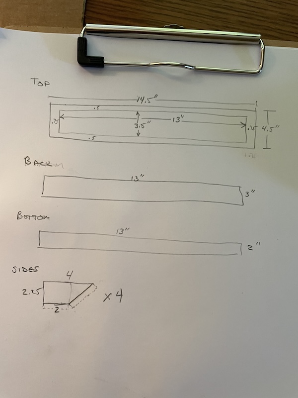
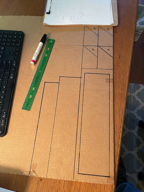
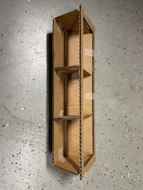
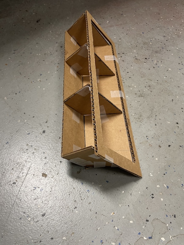
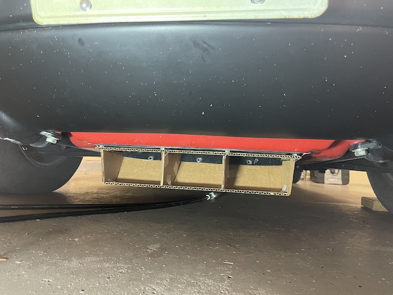
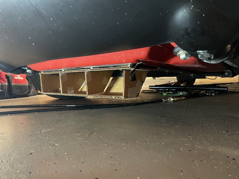
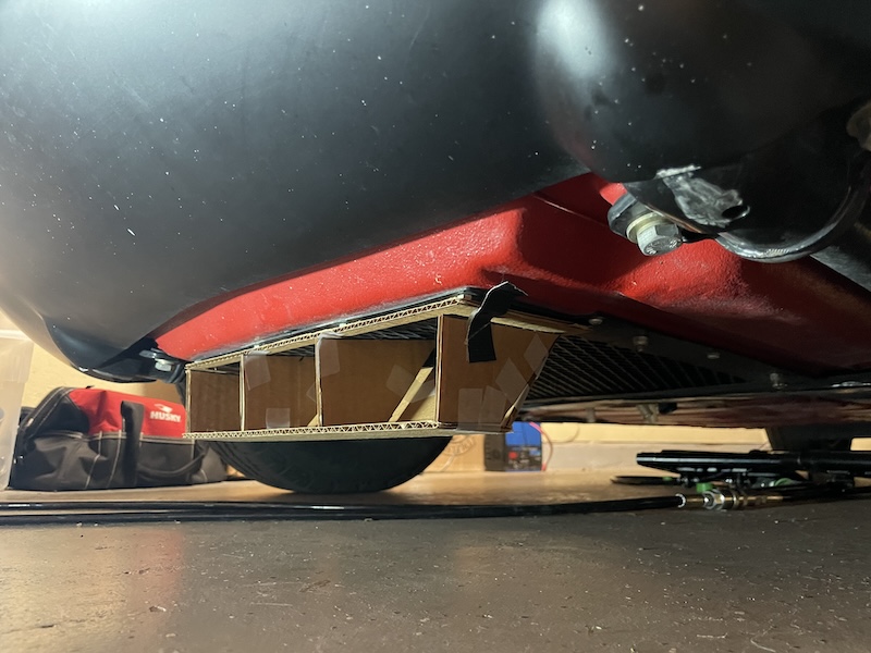
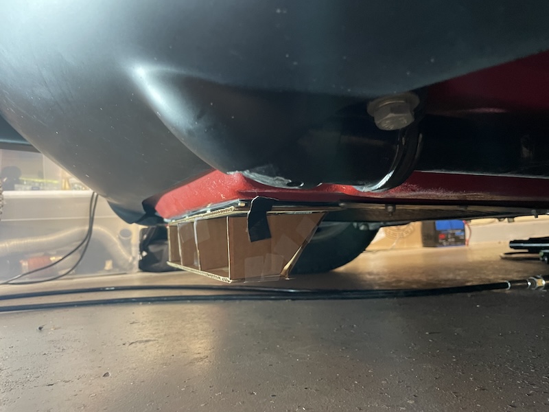
Posted by: friethmiller Apr 16 2024, 08:15 PM
Ok, I got a chance to disassemble the condenser unit and potentially make some of the changes that @http://www.914world.com/bbs2/index.php?showuser=27135 recommend to hopefully increase air flow/make my a/c work like it should. A few things I noticed:
1) There has got to be a better way to bolt the condenser and fan to the bottom plate without having to sandwich it all together with the black box - all at the same time. I will design something for this.
2) The area for the intake air could be increased! I will cut the front back about an inch or so to allow for about 40% more air. This will require modifying the front of the box just a bit (see pics for marks on the trunk). This should help the problem for sure. I will also add my new intake scoop!
3) The fan kind of sucks! It's a 12"x12". I'm sure I could up the CFM with a better fan like a 12" perma-cool 2300 cfm. Suggestions?
4) The condenser isn't much better - it's a 12"x14" generic parallel flow unit. I'm sure Rick will be all over of this. Question: if I upgrade this item now, how will I be able to capture the refrigerant before swapping it out?
5). The condenser had a leak at one of the connections to the condenser and it has eaten the paint on the bottom plate. I have stopped the leak, thankfully - verified with my new leak detector. I will clean, sand, and repaint.
Here's some pics: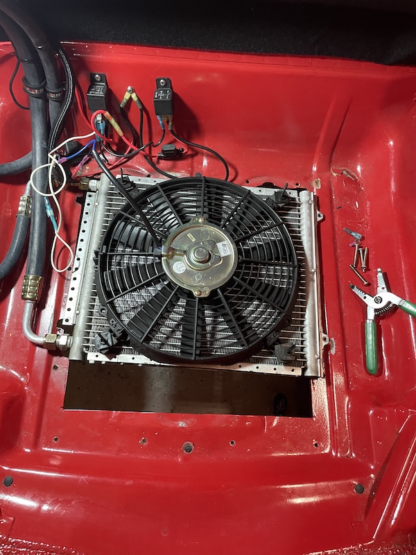
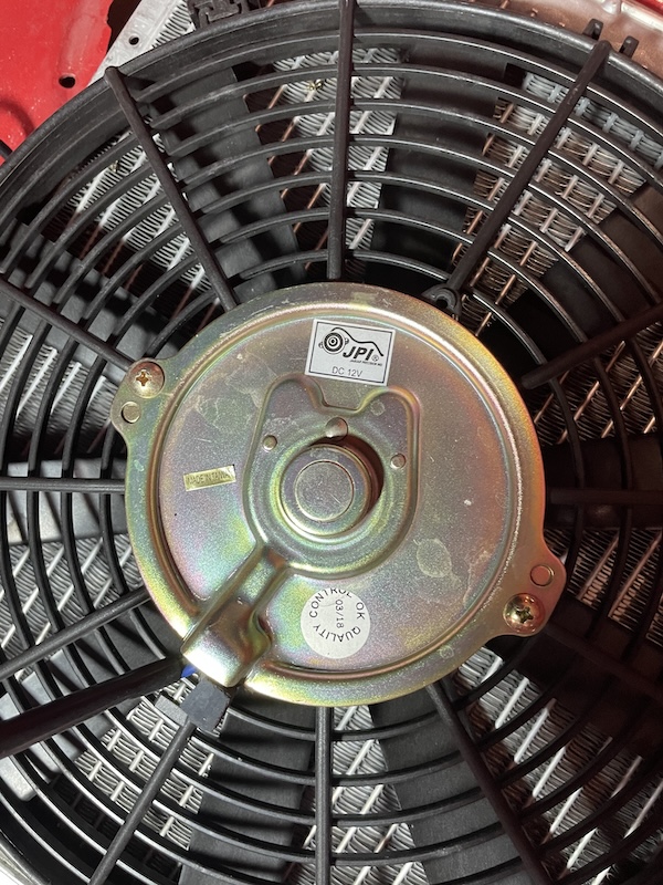
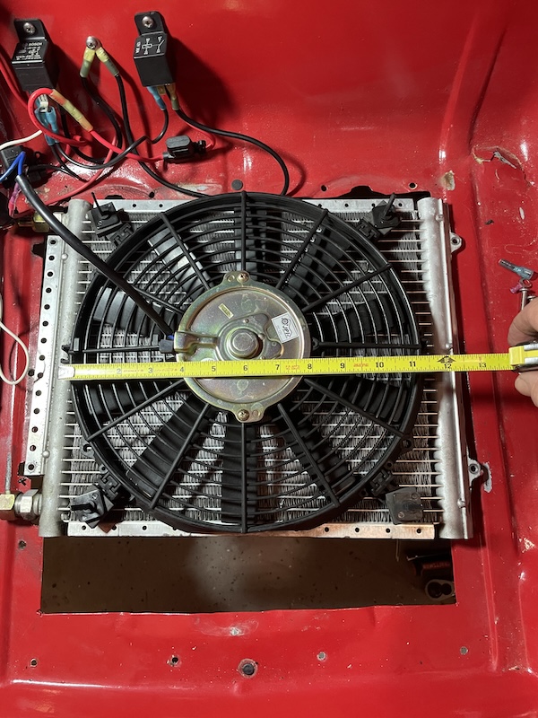
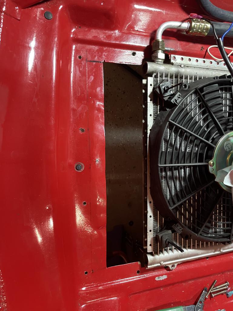
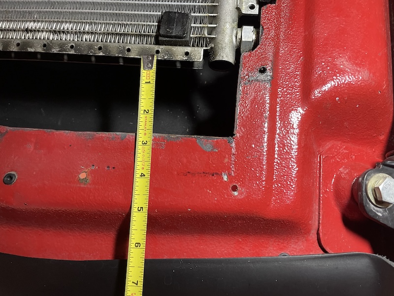
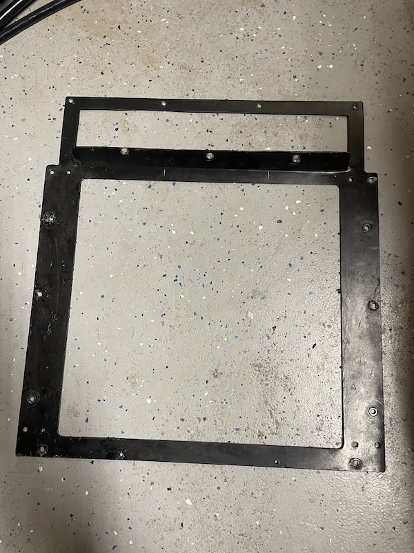
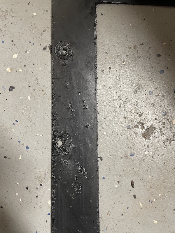
Posted by: technicalninja Apr 17 2024, 09:25 AM
I like the shit out of "super cool" condensers from these folks.
https://www.oldairproducts.com/products?keyword=condenser
They make them here in N Texas.
I put a big one in a 50' Dutch Star motorhome.
Replaced a HUGE tube and fin with a relatively tiny supercool. The original manufacture went bankrupt, and the OE stuff was NLA.
Kicked ass and was far superior to the original.
Original owners ALWAYS had to run the roof air during summer travel.
After the rebuild they NEVER had to run the roof moving.
I'd sandwich two of the biggest I could shoehorn into the frunk.
Probably 16/18 or 18/17...
As for fans yours SUCKS!
blades are shaped for a puller and they just reversed polarity. Stupid!
You will need the largest PUSHER available. I'm usually hunting Spal shit or a specific OE set up.
I worry about the fan...
Most are designed for vertical installation and the thrust surfaces/bearings may not be up to the task of a horizontal installation.
Might not be an issue but worth keeping the back of your mind.
Make SURE whatever you buy is a designated pusher. Pretty much all of the motors can run backwards but unless it has perfectly flat blades (which SUCK!) the blades will definitely have an intended direction and the "cupping" will be shaped accordingly.
My source for hoses and connections:
https://coldhose.com/?utm_source=google&utm_campaign=cold-hose&gad_source=1&gclid=EAIaIQobChMIl72a3sXJhQMVnE9HAR1KSwhWEAAYASAAEgJNP_D_BwE
I prefer steel reduced barrier stuff. Both the hoses and the crimp connectors have to show reduced barrier. DO NOT reuse old hose if possible.
A "rule of thumb" for entrances and exits is 33% of the core's face...
This is with proper ducting.
The exit is fine.
The entrance sucks big donkey dicks...
Your upside-down periscope may help but I am planning on a front entrance for my system.
Hope this helps.
I have a nice hydraulic crimper that makes short work of the hoses...
Posted by: technicalninja Apr 17 2024, 09:49 AM
Mounting condenser notes:
The SuperCool condenser I stuck in the MH came with what looked like cheesy mounts.
These were thin straps of SS that wern't very strong.
Bend them into Z shapes and mount the condenser with 4 Z bends.
This allows for what I call a "floating" mount.
The condenser will vary nearly 400 degrees over its life.
You rigid mount anything aluminum which goes through 400-degree changes, and you WILL break it somewhere down the road.
The SuperCool condenser has flanges with a bunch of holes down the sides.
The straps and the holes make it easier to install...
The proper stack is discharge hose to lower condenser with a bridge from the output of the first condenser into the input of the second then output of second to receiver drier.
Condensers are normally discharge to top with liquid line coming from bottom.
You reverse these two and your system will die rapidly.
The oil NEEDS to come out the bottom!
It will get trapped in the condenser otherwise.
The reason I'm including this is the way I have designed is the exact opposite with the liquid line coming from the "top" of the stack instead of the bottom.
Both of these cores are horizontal, and the oil flow is probably not an issue but once again, something to think about.
I'd over oil a bit and watch how the sight glass looked.
If it's bright green I'm happy.
If it looks like water running in the drier, I'd redesign...
Clear means no oil, green means oil.
Posted by: friethmiller Apr 17 2024, 09:49 AM
@http://www.914world.com/bbs2/index.php?showuser=27135 - yes! Thank you. First off, I was able to buy a leak detector and get a wrench on either side of that front inlet and tighten it down [wasn't exactly that tight before]. Leak detector no longer detects anything [at the highest sensitivity]. I'm going to be doing a lot changes based on your suggestions. I'm looking at flipping things around and having a better quality fan pull instead of push. I'm going to stay with this condenser for now but will be reworking things so I can more easily change it out, if I need to. I'm also looking at another air intake up front, like you mentioned, but haven't got that far on the design side yet. Working on this while also rebuilding the LE has got me super busy. This should take me a few weekends
Posted by: Literati914 Apr 17 2024, 09:54 AM
In order to improve the airflow into the frunk mounted AC condenser, has anyone tried creating an air inlet by opening up the holes behind the front bumper that have the biground rubber plugs, like guys who run 914-6 engines do when building a front mounted oil cooler and ducting into the frunk floor?
GT opening for a condenser instead of oil cooler or radiator (Suby/v8 cars). Sounds like the way to go if you are serious about a/c. It’s the optimal location for airflow.
I like this idea the best.. would A GT opening (both bumper and Valance) be sufficient for air to the condenser? I suppose even at GT oil cooler shroud could be incorporated and may even help the flow? Thoughts?
.
Posted by: technicalninja Apr 17 2024, 10:06 AM
You're already in...
I wouldn't waste my time on that itsy bitsy core.
You live in HELL!
Design accordingly...
You're already there!
I'd get my tape measure out and figure out how big a core you can fit.
Depending on your hose set up a proper big single core might just fit.
The connections will be the same most likely...
#8 and #6.
Posted by: friethmiller Apr 17 2024, 11:40 AM
You're already in...
I wouldn't waste my time on that itsy bitsy core.
You live in HELL!
Design accordingly...
You're already there!
I'd get my tape measure out and figure out how big a core you can fit.
Depending on your hose set up a proper big single core might just fit.
The connections will be the same most likely...
#8 and #6.
I think/know you're right. So, pull air from a new hole/intake from the valance/bumper area. Screw the bottom intake crap and use the entire area for the condenser and fan. This seems like a better way to go. I'm all for it!Posted by: friethmiller Apr 17 2024, 04:53 PM
@http://www.914world.com/bbs2/index.php?showuser=27135 - I called and talked with one of the techs at old air. He said parallel flow condensers should not be mounted flat - like I have. It must drain to the smaller, liquid side. Crap! More redesign. I may just put on a better 12” fan, increase the intake air, and see how it goes 
Posted by: technicalninja Apr 17 2024, 06:58 PM
I disagree with him...
Read my previous posts.
I've covered the oiling issue already.
Lots of things have condensers and evaporators at not "textbook" angles.
Don't automatically believe every expert you speak with.
Most are FAR less expert than they think they are...
He is RIGHT about vertically mounted condensers needing the input at the top and the exit at that bottom. Do it backwards and the reaper awaits.
Laying the condenser flat is not a deal killer. I'm more worried about fan life myself...
Posted by: Chris914n6 Apr 17 2024, 11:57 PM
From what I can tell what you have now should work fine. The dealer options worked fine.
You need a PULLER fan. Pushers don't work worth a turd. If TN was right you can just reverse the wires on the fan you have and it will actually work as designed.
Skinny fans won't move much air, so it becomes a space issue. The Chinese don't do CFM measurements, they just copy and most of their fans under preform. If the current fan doesn't cut it buy a thick Spal fan.
The cardboard duct can be trashed.
It would be better to structure the opening further forward under the spoiler/bumper with it flowing wide and shallow to the cond inlet. The mouth can be as big as needed but really your limited to the area of the exit hole.
Pardon my crude drawing, but this should solve most of the problems by changing placement and maybe a new enclosure.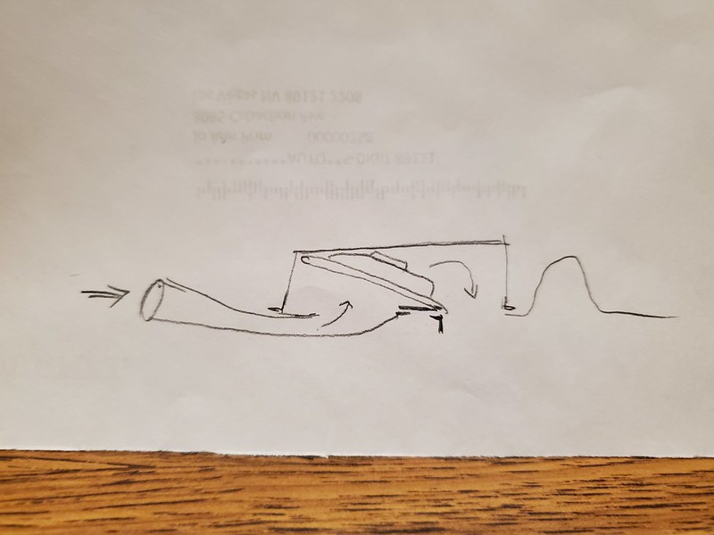
Posted by: friethmiller Apr 18 2024, 09:28 AM
From what I can tell what you have now should work fine. The dealer options worked fine.
You need a PULLER fan. Pushers don't work worth a turd. If TN was right you can just reverse the wires on the fan you have and it will actually work as designed.
Skinny fans won't move much air, so it becomes a space issue. The Chinese don't do CFM measurements, they just copy and most of their fans under preform. If the current fan doesn't cut it buy a thick Spal fan.
The cardboard duct can be trashed.
It would be better to structure the opening further forward under the spoiler/bumper with it flowing wide and shallow to the cond inlet. The mouth can be as big as needed but really your limited to the area of the exit hole.
Pardon my crude drawing, but this should solve most of the problems by changing placement and maybe a new enclosure.
Thanks Chris. A few things I like about this design is that it trades exhaust for more intake space, which I need. Additionally, the puller fan set-up. That said, as you mentioned, the enclosure would likely need to be increased in height (at a minimum). The existing condenser is 14"x12"x1" and it sits inside a 16"x16"x4" box. Another issue I'm dealing with is the full-sized spare tire. It mounts to the top of the box and I have a factory style funk cover on top of that. I've customized this cover to work with everything. I guess I'm trying to find the optimal solution here based on my constraints.
Again, thanks for your input, TN's, and others. I'll keep this all in mind moving forward. Just based on expenses, I may implement something quick to improve the current situation then plan and execute on a better, more permanent fix later this year.
Posted by: 914sgofast2 Apr 18 2024, 12:52 PM
I would change that design by having the outside air enter the front of the air box, instead of the bottom. That way it is similar to how many people mount front oil coolers for the 914-6 engines in the frunk when they collect the cooler outside air thru the front bumper cutout, instead of from under the frunk floor, and then exhaust the air under the car from the frunk floor, similar to how the original A/C systems exhausted their hot air under the car. This would require building some metal ducting from the front bumper area to the original A/C air box' front and opening up the front of that air box. Think of how Mike Cairo's Six Project is making a new front oil cooler housing.
Powered by Invision Power Board (http://www.invisionboard.com)
© Invision Power Services (http://www.invisionpower.com)