Printable Version of Topic
Click here to view this topic in its original format
914World.com _ 914World Garage _ SOT: electrical gurus check in...
Posted by: dlo914 Nov 30 2012, 12:45 AM
So i've retrofitted some LED rings into my daily driver, but i'm only using the LEDs as the running lights and using the filament bulb when brakes are applied. how would i go about using the LEDs for both running and braking light usage? i know i'm suppose to add a resistor to each positive LED wire, but i'm so confused as to what OHM rating or % etc i'm suppose to use. The guys at two radioshacks were useless.
Here's how they look at the moment: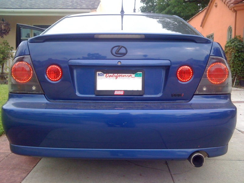
Posted by: Tom Nov 30 2012, 04:49 AM
LED brilliance is controlled by current flow. Current flow is adjusted by the resistance in series with the LED. Add more resistance, dim the output of the LED.
Less resistance = brighter until you over power the LED and it burns out.
Not surprised by the lack of knowledge at Radio Shack.
I will give your problem some thought and draw a circuit for you later today.
Tom
Posted by: Tom Nov 30 2012, 05:58 AM
Are these rings a plug in to the regular socket where the normal bulb went?
If so, You are going to have a hard time getting inside the module to effect a change in brilliance. You should be able to put brake light plug in modules also and they would be engineered for extra brilliance.
Tom
Posted by: Spoke Nov 30 2012, 08:26 AM
For the brake light with higher intensity, as Tom said, use a lower value resistor.
To do this, you'll need to know how the unit is wired.
Got a pic and/or model number of the unit?
You want to use them as both brake lights and running lights.
For the running lights, there are only 2 wires.
For running lights and brake lights, you'll need 3 wires like the typical 1057 brake/running bulb.
Posted by: Bartlett 914 Nov 30 2012, 08:33 AM
I am doubtful that adding resistance will give satisfactory results. You need to pulse the lamp. By varying the duty cycle, you will dim the LED
Posted by: Nine_14 Nov 30 2012, 09:12 AM
http://en.wikipedia.org/wiki/LED
Posted by: Tom Nov 30 2012, 02:24 PM
Here is a simple led circuit than will allow the running light LED's to be one brilliance and the brake lights to be a higher brilliance. Your ring LED's will be hard to modify to do this.
Say each LED was a .2 watt. With (it looks like over a hundred LED's) that would require a 25 watt or bigger resistor. ( current thru one section of the circuit is constant thru the whole circuit.) Resistors this size will not be cheap. Smaller ones for pennys. Also if this is a plug in module, it will be difficult to modify to have the brake light circuit in parallel as in the simple drawing. You would also have to have terminals on the headlight switch to allow rewiring to make the brake light circuit the same brilliance reguardless if the headlights are on or not.
Here is how the circuit works:
When headlights(running lights) are on, the path is from batt + to closed contacts of the headlight switch, thru R1, to LED's to ground. If brakes are applied, you will have a parallel circuit with R2 also connected to the LED's. Resistors in parallel are less ohmic value than either resistor. Hense the brake lights and running lights would get brighter.
With no headlights on, ( the doted line is hooked up) the path is a parallel one from batt + thru brake light switch to headlight switch thru parallel resistors to LED's to ground. The headlight running light LED's and brake light LED's would operate.
hope this has shed some light ( no pun intended) on your delima. I don't know how auto lights are dimmed using LED's, but I suspect it is a cycle of on/off pulses to the LED's as they are very fast in operation. Say running lights get a pulse rate of 60 and brake lights. seperately wired, would have a pulse rate of 100. Brake lights would be brighter.
Tom
Attached thumbnail(s)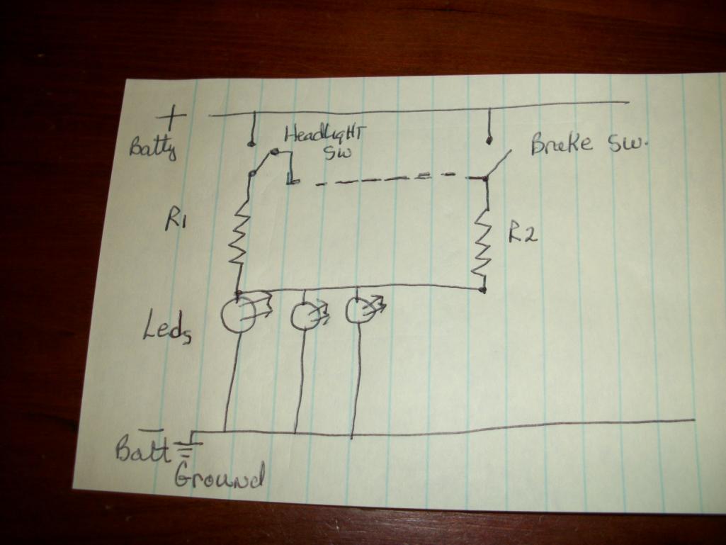
Posted by: mr914 Nov 30 2012, 03:04 PM
Temporary, or could be permanent...
Buy a variable resistor/potentiometer
Put in circuit and adjust to desired brightness
Remove and measure with ohm meter.
Go to rat shack and buy resistor of appropriate value
Posted by: Dave_Darling Nov 30 2012, 05:23 PM
All the automotive LED taillights I know of blink. Drives my wife up the wall, because she can see them flicker. (Better eyesight, or maybe just less persistence of vision than many of us.) Vertical bar lights, especially Cadillacs, are the worst. But they all do blink.
If it were as simple as putting a resistor in line with the LEDs, I think they probably would do it. So there is likely a reason they use the blinking circuitry instead. Perhaps the LEDs last longer that way?
--DD
Posted by: Spoke Nov 30 2012, 05:52 PM

If it were as simple as putting a resistor in line with the LEDs, I think they probably would do it. So there is likely a reason they use the blinking circuitry instead. Perhaps the LEDs last longer that way?
--DD
The resistor - LED current limiter is the simplest solution and the least efficient as far as power/energy is concerned. The resistor drops voltage and dissipates significant power and heat.
There are a myriad of LED drivers on the market that use a high frequency switching method to efficiently drive the LED. The efficiency can reach 95%. That is 95% of the power is dissipated in the LED.
For the resistor current limiter, it is possible that less than 30% of the power is dissipated in the LED and 70% in the resistors.
The downside of the switching current limiter is complexity and cost. You need an integrated circuit switching converter, inductor, several capacitors, a schottky diode, and some resistors.
Posted by: Spoke Nov 30 2012, 06:07 PM
Here's a switching converter to efficiently drive an entire bank of LEDs. This circuit shows an input voltage of 3 to 6V but the same architecture can be used with 12V in.
To dim the LEDs, provide a lower voltage at the EN input. This is easily done with resistors. This particular converter doesn't accept different level input voltage to dim the LEDs but other chips do.
Attached image(s)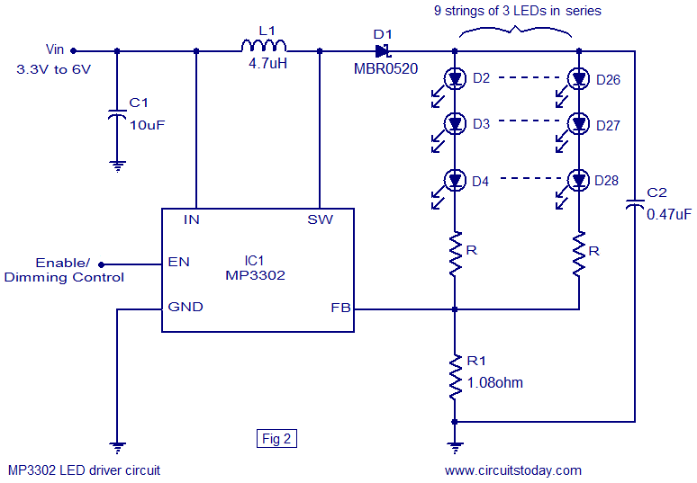
Posted by: stugray Nov 30 2012, 07:34 PM
There are off the shelf drivers that can do this.
Google 'buckpuck'.
If I knew the max current when on full, I could suggest a converter that takes 12VDC and regulates LEDs.
Stu
Posted by: Spoke Nov 30 2012, 07:51 PM
There are off the shelf drivers that can do this.
Google 'buckpuck'.
If I knew the max current when on full, I could suggest a converter that takes 12VDC and regulates LEDs.
Stu
I am familiar with the Buckpuck.
The Buckpuck is a great product line manufactured in the USA by a small company called LEDdynamics in Vermont.
The switching IC in the Buckpuck product line is MP2483 from MPS out of San Jose, CA. I worked for them at the time and the Buckpuck was one of my design wins.
Posted by: nukepipe Nov 30 2012, 08:42 PM
So i've retrofitted some LED rings into my daily driver, but i'm only using the LEDs as the running lights and using the filament bulb when brakes are applied. how would i go about using the LEDs for both running and braking light usage? i know i'm suppose to add a resistor to each positive LED wire, but i'm so confused as to what OHM rating or % etc i'm suppose to use. The guys at two radioshacks were useless.
Here's how they look at the moment:
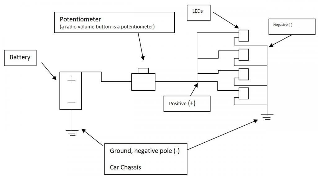
You could use a potentiometer (a volume button from an old radio, analog to be spesific, is a potentiometer) since the potentiometer is just a variable resistor. When you find your desire light intensity you can use a multimeter to find the resistance (ohms) on the potentiometer . After that you can buy a resistor that would be near the ohms you need or you just can leave the potentiometer fixed.
Is as simple as positive wire to one end of the potentiometer and the other end will distribute the power to the leds positive side (since this is for the non brake light).
Here is a simple diagram without engineering or electrician symbols excepts for the ground symbol (electrical engineer typing).
Hope this help.
Attached thumbnail(s)
Posted by: aircooledtechguy Dec 1 2012, 12:09 AM
I'm probably missing something here, but if you are trying to simply use LEDs for the brakes, replace your incandescent bulbs to LEDs and drive away happy. They can be had in any brightness and intensity you want at www.superbrightleds.com
Posted by: falconfp2001 Dec 1 2012, 02:58 AM
I would say you need to check this site out
http://www.superbrightleds.com/cat/flashers-load-resistors/
Posted by: bperry Dec 1 2012, 12:29 PM
Here is a link to a DIY article on how to wire up LEDs for DRL and turn signals that
uses resistors for brightness control.
http://tech.bareasschoppers.com/diy-projects-mods/rear-lights-mod/
It is a fancier version of the circuit that Tom drew up.
--- bill
Powered by Invision Power Board (http://www.invisionboard.com)
© Invision Power Services (http://www.invisionpower.com)