Printable Version of Topic
Click here to view this topic in its original format
914World.com _ 914World Garage _ Subaru to 914 trouble fixes
Posted by: 904svo Dec 3 2012, 11:21 AM
Here are some of the fixes I used when installing a 2007 Subaru WRX engine in my car.
I did not want to change any of the wiring in my car as it has a 1973 914 wiring harness installed
in it. I wanted to keep the stock gauge cluster in it but adapt it to a Subaru engine to look stock.
Here are some of the troubles I found and the fixes I used
#1 Tach
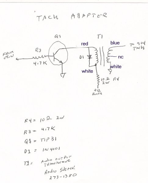
Convert the 5 volt output signal from the Subaru to a high voltage pulse that the 914 tach requires.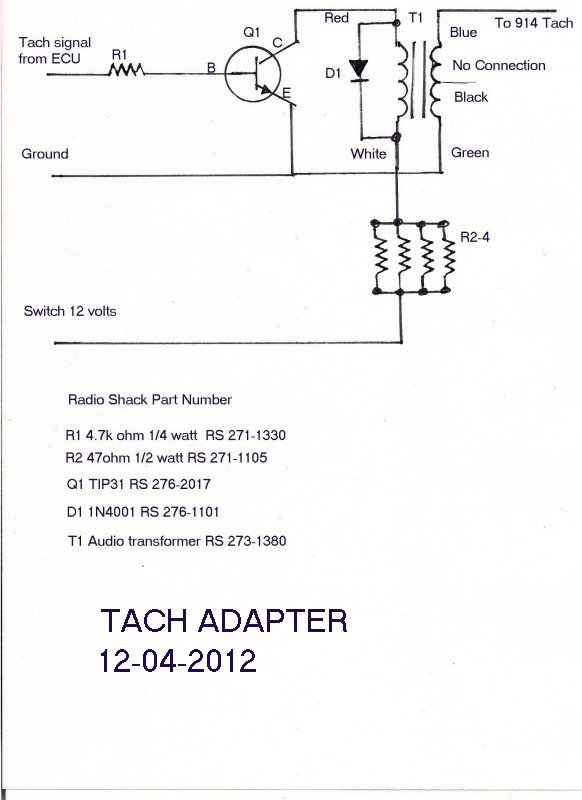
#2 Starter circuit
Added a hot starter relay which removed all the Subaru starter check circuits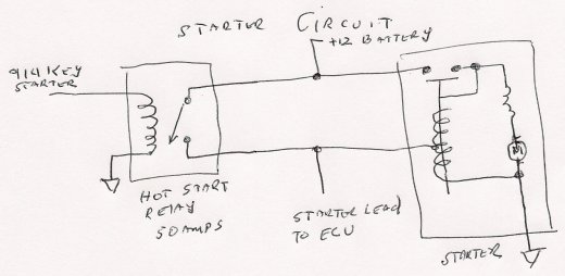
#3 Stop Fuel level DTC’s
Note if connected to 914 low warning , this will reduce power level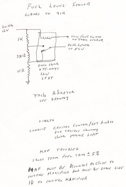
#4 Add Cruise control lights/Check engine lights for trouble shooting DTC’s
#5 Make the 914 ignition key look like a Subaru ignition key for the immobilizer circuit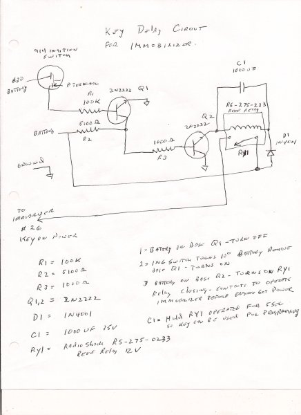
#6 Oil light and Oil pressure gauges/ Oil temperature gauge converted to Engine temperature gauge
To convert Oil temperature to Water temperature gauge add a 75 ohm resistor in series with the
extra temperature lead ( used for stock Subaru gauge panel) to the oil temp gauge
If you have a Oil pressure/Oil light sender added to your gauge cluster just replace the Subaru Oil
Pressure switch and use the same wiring otherwise just wire the Subaru sensor to the Oil lamp.
Connect the Subaru alternator (Black/white) lead to the 914 Gen lamp bulb.
If you see any poroblems let me know.
Attached image(s)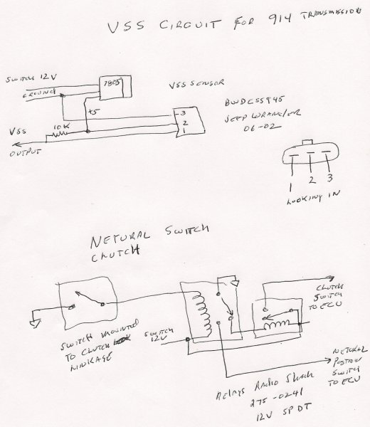
Posted by: wingnut86 Dec 3 2012, 02:37 PM
Hmmm, I like:-)
Posted by: strawman Dec 3 2012, 03:42 PM
This is great info! I will build the tachometer adaptor ASAP and report back if this works with the EJ22T ('94 USDM Subaru Legacy Turbo) ECU. Thanks! 
Posted by: strawman Dec 4 2012, 01:28 AM
I was able to chase down most of the needed parts for the tach adapter from two different RatShacks in the area. However, it seems like the Audio Output Transformer (Part #273-1380, $2.99/each) is not drawn correctly in your diagram. See the image below for details from RatShack's website: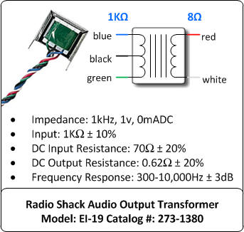
Here is also a picture of the back of the Audio Output Transformer package: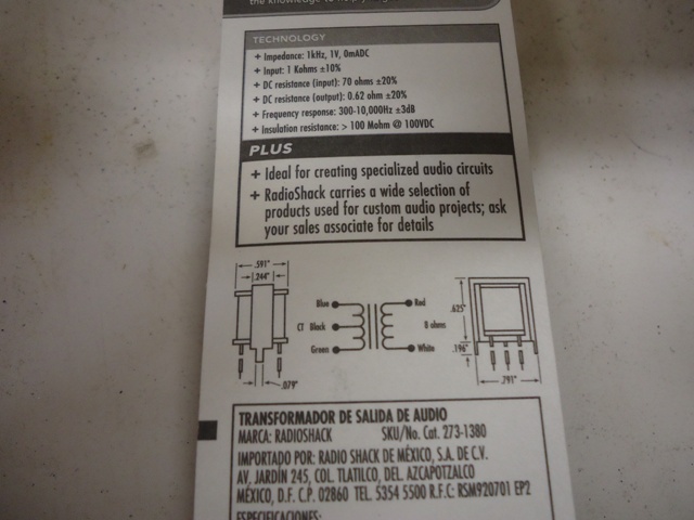
I am assuming the following:
1. The Q1 collector wire goes to the BLUE 1K-Ohm input on the transformer.
2. The Center Tap (BLACK) wire from transformer should intercept the cathode side of the diode on its way from the BLUE 1K-Ohm input wire (anode side) to the Green 1K-Ohm input of the transformer.
3. 12V ignition power goes to resistor R4 to GREEN 1K-Ohm input on the transformer (at the cathode intercept).
4. The RED 8-Ohm output wire on the transformer goes to the 914 tach signal.
Where does the GREEN 8-Ohm output wire from the transformer go? I am not familiar with the "triangle" symbol that you used; does it signify ground?
Also, how important is the wattage for resistor R4? RatShack only stocks 1-Watt 10-Ohm resistors in the store, but I can order 2-Watt 10-Ohm resistors (10 for $1.86 from RatShack online).
Another question: what wattage is necessary for resistor R3? The local RatShack store only stocks 1/2-Watt 4.7k-Ohm resistors, but I can order 2-Watt 4.7k-Ohm resistors online (10 for $1.86 from RatShack).
Finally, where does the emitter signal from transistor Q1 go? Again, I am not familiar with that triangle symbol you used...
Thanks in advance!
Geoff
Posted by: euro911 Dec 4 2012, 01:49 AM
This is some good stuff 
Posted by: dian Dec 4 2012, 03:16 AM
very interesting.
what about the speedometer?
Posted by: 904svo Dec 4 2012, 07:36 AM

I was able to chase down most of the needed parts for the tach adapter from two different RatShacks in the area. However, it seems like the Audio Output Transformer (Part #273-1380, $2.99/each) is not drawn correctly in your diagram. See the image below for details from RatShack's website:
Here is also a picture of the back of the Audio Output Transformer package:
I am assuming the following:
1. The Q1 collector wire goes to the BLUE 1K-Ohm input on the transformer.
2. The Center Tap (BLACK) wire from transformer should intercept the cathode side of the diode on its way from the BLUE 1K-Ohm input wire (anode side) to the Green 1K-Ohm input of the transformer.
3. 12V ignition power goes to resistor R4 to GREEN 1K-Ohm input on the transformer (at the cathode intercept).
4. The RED 8-Ohm output wire on the transformer goes to the 914 tach signal.
Where does the GREEN 8-Ohm output wire from the transformer go? I am not familiar with the "triangle" symbol that you used; does it signify ground?
Also, how important is the wattage for resistor R4? RatShack only stocks 1-Watt 10-Ohm resistors in the store, but I can order 2-Watt 10-Ohm resistors (10 for $1.86 from RatShack online).
Another question: what wattage is necessary for resistor R3? The local RatShack store only stocks 1/2-Watt 4.7k-Ohm resistors, but I can order 2-Watt 4.7k-Ohm resistors online (10 for $1.86 from RatShack).
Finally, where does the emitter signal from transistor Q1 go? Again, I am not familiar with that triangle symbol you used...
Thanks in advance!
Geoff
My mistake heres the corrected drawing. The triangle is a ground symbol. R3=1/4 watt R4 must be greather that 2 watts. You can use 4 47ohm 1/2 watt resistors
connected in parallel
\
Posted by: 904svo Dec 4 2012, 07:41 AM
very interesting.
what about the speedometer?
If you use the Subaru transmission the VSS is build in and you can use a late model
Porsche speedometer.
If you use a 914 transmission you use the mechinical drive off the back of the transmission to drive the stock speedometer and you have to install a VSS circuit
on one of the output flanges with either 4 or 5 impulses per rev.
Posted by: 904svo Dec 4 2012, 08:43 AM
I mounted the circuit in a small case and installed it behind the tach using he factory wires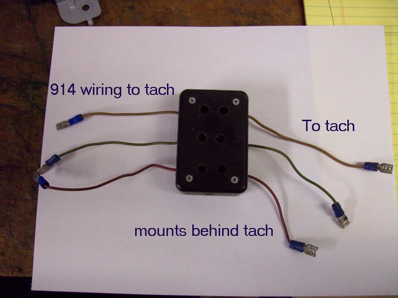
Posted by: 904svo Dec 4 2012, 11:07 AM
Tach adapter in first post has been change to use Radio Shack Parts with numbers
Posted by: strawman Dec 4 2012, 01:05 PM
This is truly outstanding stuff, and I thank you for posting/clarifying the tach info. You da man! 
Posted by: strawman Dec 12 2012, 11:19 PM
Larry really is a great guy, and we Suby-conversion guys should really appreciate folks like him contributing to 914World. He's helping me figure out why my tach converter is not working (likely solderer error...) for my 1994 Subaru Legacy Turbo ECU. Stay tuned!
Posted by: wingnut86 Dec 13 2012, 09:11 AM
Agreed Strawman!
Once I give my wife "Her" side of the garage back, I'll be allowed to touch my 914 again:-{
Posted by: strawman Jan 1 2013, 02:29 PM
The tach converter works! Be sure to follow the directions to the letter (I originally had the Collector and Emitter connections backwards on the TIP31 transistor). Thanks again Larry! 
Posted by: jpnovak Jul 15 2013, 01:05 PM
Reviving this thread to ask a question.
I have a Suby transmission in my 914. I want to drive a speedometer that fits in the dash. In an earlier post you mention that the VSS signal from the transmission will drive a stock, late model speedometer.
The Suby seems to put a 5V signal. It is supposed to have 4 pulses per revolution. The 911 style speedometer has eight pulses per revolution based on the magnetic disc in a 915.
Can anyone verify the output signal from the VSS?
I am currently using a bicycle computer but I have found that its top speed is not quite high enough.  It was certainly easy to wire in.
Thanks
Posted by: 904svo Jul 15 2013, 03:15 PM
On another post here they talk about a aftermarket unit that will fix this.
I think it was in this post.
http://www.914world.com/bbs2/index.php?showtopic=110990&hl=
Posted by: DBCooper Jul 15 2013, 03:39 PM
Another option. This is mine, aftermarket VDO electronic progammable, fits in the hole and works with the stock Subaru sender: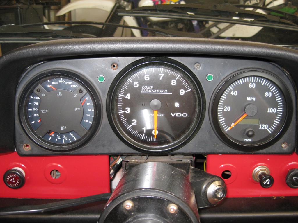
The tach adapter showed up after mine was already done, but it's OK, I like my tach.
Powered by Invision Power Board (http://www.invisionboard.com)
© Invision Power Services (http://www.invisionpower.com)