Printable Version of Topic
Click here to view this topic in its original format
914World.com _ 914World Garage _ LED Taillights
Posted by: Spoke Jan 26 2013, 02:40 AM
I've wanted to convert my 914 taillights to LED for a while but never got around to it.
Finally I started working on the design of the taillights. This will be a single custom PCB for each side and will have all the LEDs and control circuits on it. One PCB will be used for both sides.
The plan is to remove the existing plastic reflector and bulb assembly and mount a custom board in its place. With proper standoffs, I should be able to mount the board using the same 2 screw holes that secure the reflector.
I'm trying to decide now how many LEDs to use for each purpose. Right now, I have 8 LEDs for the backup lights, 20 LEDs for the running/Brake lights, 24 LEDs for the turnsignals, and 4 LEDs for the side marker.
I've been observing modern cars with LED taillights and some use a few LEDs (like 8) and some a lot (+20).
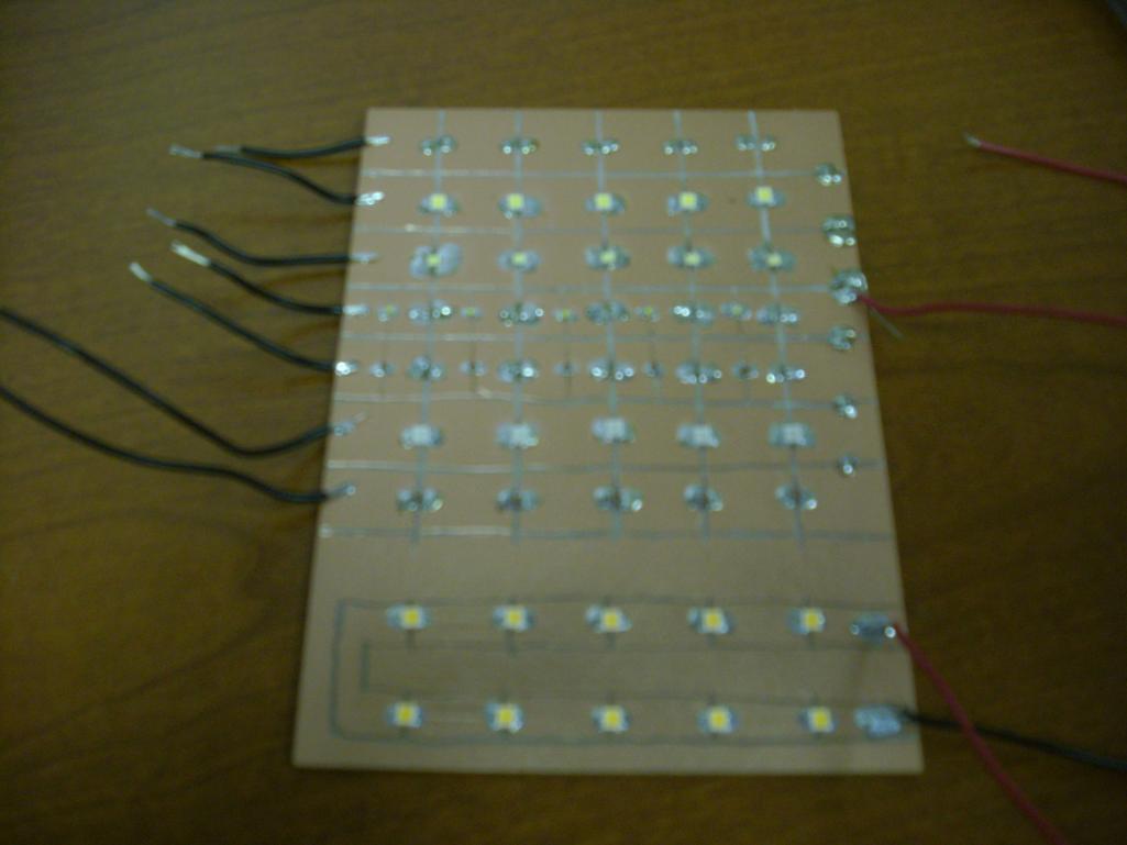
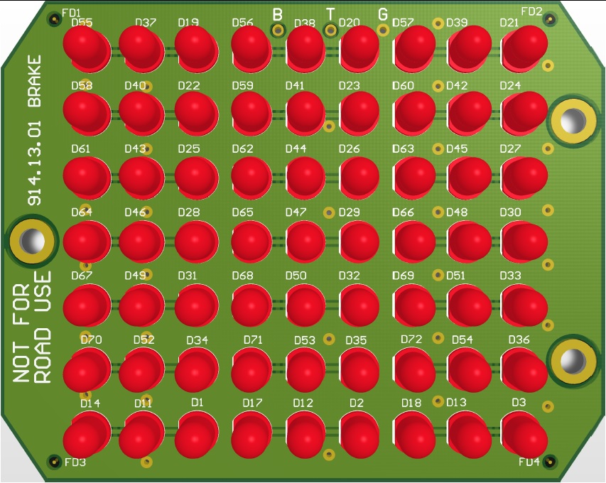
I would like your opinions on how many LEDs you think would be good to use. On the board below, the LEDs are spaced about 0.7 inches apart. These will be medium brightness white LEDs. (I'll let the lenses provide the color).
The first cut at the board is shown below for the driver's side. The side marker LEDs will be right angle LEDs pointing out the side of the board. They can be seen on the extreme left side of the board.
If these work out, I could manufacture them for World members. One thing though, they won't be cheap. The LEDs are about $0.50 through Digikey and there are more than 55 LEDs on each right now. Plus there's 2 dc-dc converters for providing constant current for the tail/brake and turnsignal LEDs.
Cheers

Attached thumbnail(s)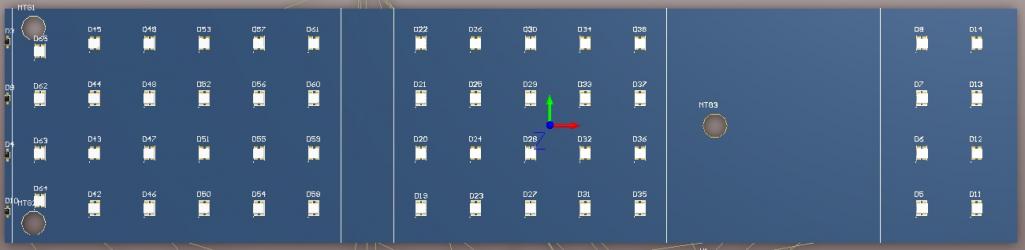
Posted by: euro911 Jan 26 2013, 03:15 AM
Nice. Are you going to follow up with front light assemblies?
Posted by: rfuerst911sc Jan 26 2013, 04:58 AM
I like this please keep the forum updated with progress. In my opinion the maximum LED's you can use for running/brake lights is preferred so we can make the back of our cars as visible as possible. Our cars are very low and with OEM lighting leave a lot to be desired for rear visibility, that's why so many are adding 3rd brake lights.
Posted by: Bartlett 914 Jan 26 2013, 08:09 AM
Good Idea. I like to see lots of leds. I don't like the look of a few bright lamps. I think lots of leds will give a more even display. Our reflectors are getting old and often have the chrome flaking off. Should be a good replacement
Posted by: Cairo94507 Jan 26 2013, 08:22 AM
I would definitely be in on this buy. I like your configuration as is and would rather see more than less LED's as these cars are hard to see.
I would like to see a kit for the front that would replicate the european design turn-signal bucket configuration and the US version. I would be happy to convert my Six to these lights during the build.
I would still add the high-mount 3rd brake light too. 
Posted by: scotty b Jan 26 2013, 08:47 AM
Do a search. Someone was putting quite a bit of effort into doing this a couple years ago. I don't recall if it ever got finished, but IIRC he was close
Posted by: Mikey914 Jan 26 2013, 08:57 AM
I'd do the math with the brightest LEDs available and see what the cost winds up at. I think you'll find these get pretty expensive, my guess is you'ld be into these at $75 a pop ($150 a set) once you got all your costs together. Maybe you can do a little better, but these things add up quick. The key is to sell enough units to spread the cost out over more. You may be able to make them at $35 a pop if you can do 100 sets, it's just seeing what the market for these are, and investing a big chunk of change to get the numbers to work.
I wish you luck.
PS you may want to check with the 1st guy to see why he didn't make them, there may be some issues that are not readilly apparent here.
Posted by: wndsnd Jan 26 2013, 09:23 AM
Or,
You could just do this.....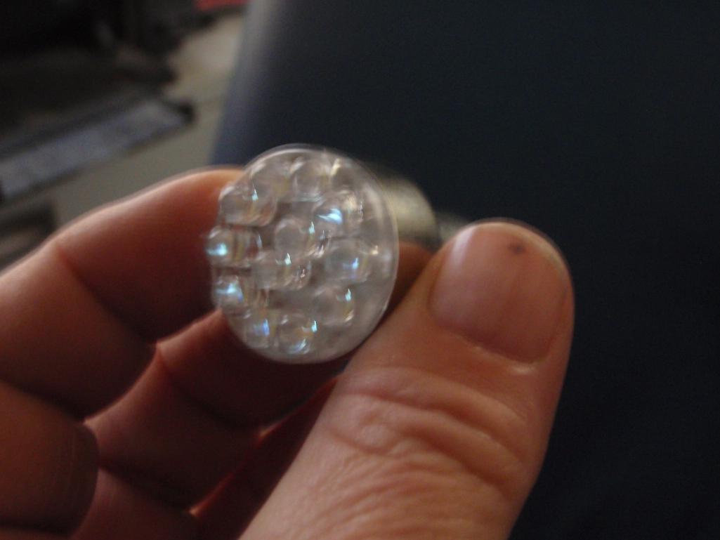
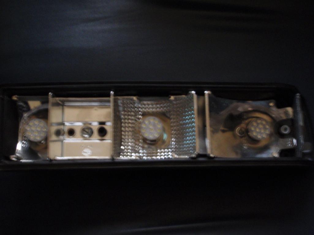
Little Ones Too......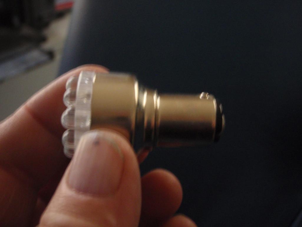
I work for an LED Manufacturer, so I ordered these up for the car, I haven't tried them yet.
Sorry for the crappy photos
John
Posted by: GeorgeRud Jan 26 2013, 09:27 AM
I've been looking at these bulbs myself, and hope you can let us know how they work out. Seems like a nice, easy way to upgrade and hopefully make the car a bit easier to see (there's a reason that I like yellow for small cars - most visible color). You might want to put together a listing of the part numbers of the LED bulbs you used.
Posted by: wndsnd Jan 26 2013, 09:33 AM
My car isn't ready yet, so,
Maybe I can get a local volunteer to try them.
Scotty-In-NH Where are you?
Posted by: scotty b Jan 26 2013, 10:08 AM
Found it
http://www.914world.com/bbs2/index.php?showtopic=39164&hl=l.e.d.+taillights
Posted by: Tilly74 Jan 26 2013, 10:16 AM
If you're upgrading to LED's (or not, they work with regular bulbs too), you might consider a "back off light" or "taillight flasher". I know many people are concerned with getting rear-ended and protecting their precious teeners. This is usually one of the first mods I do to any motorcycle I ride regularly. The manufacturers advertise something like a 40% reduction in rear end accidents on motorcycles. Also, many newer ambulances feature a similar technology for safety reasons. If anybody wants more info on these I have a large variety of models I can order from at a decent discount as well.
This video is one of the better examples I can find. Most videos look wrong because of frame rates on the cameras. Some modules allow you to fine tune the flash rate, number of flashes, and even integrate turn signals.
https://www.youtube.com/watch?v=e368R4ttjCE
Posted by: scotty b Jan 26 2013, 10:21 AM

If you're upgrading to LED's (or not, they work with regular bulbs too), you might consider a "back off light" or "taillight flasher". I know many people are concerned with getting rear-ended and protecting their precious teeners. This is usually one of the first mods I do to any motorcycle I ride regularly. The manufacturers advertise something like a 40% reduction in rear end accidents on motorcycles. Also, many newer ambulances feature a similar technology for safety reasons. If anybody wants more info on these I have a large variety of models I can order from at a decent discount as well.
This video is one of the better examples I can find. Most videos look wrong because of frame rates on the cameras. Some modules allow you to fine tune the flash rate, number of flashes, and even integrate turn signals.
https://www.youtube.com/watch?v=e368R4ttjCE
Check out the sequential tailight vid that comes up at the end of this vid. IMHO the vertical LED's like that would look best, and making the turns sequntial would be VERY effective, as they really grab people attention
Posted by: Tilly74 Jan 26 2013, 10:33 AM
If you're upgrading to LED's (or not, they work with regular bulbs too), you might consider a "back off light" or "taillight flasher". I know many people are concerned with getting rear-ended and protecting their precious teeners. This is usually one of the first mods I do to any motorcycle I ride regularly. The manufacturers advertise something like a 40% reduction in rear end accidents on motorcycles. Also, many newer ambulances feature a similar technology for safety reasons. If anybody wants more info on these I have a large variety of models I can order from at a decent discount as well.
This video is one of the better examples I can find. Most videos look wrong because of frame rates on the cameras. Some modules allow you to fine tune the flash rate, number of flashes, and even integrate turn signals.
https://www.youtube.com/watch?v=e368R4ttjCE
Check out the sequential tailight vid that comes up at the end of this vid. IMHO the vertical LED's like that would look best, and making the turns sequntial would be VERY effective, as they really grab people attention
https://www.youtube.com/watch?v=WEREH0XDipo
Posted by: Spoke Jan 26 2013, 10:38 AM
Thanks for the replies. I'll try to address each question comment here.
"Nice. Are you going to follow up with front light assemblies?"
Haven't thought about it yet. Which function would the LEDs replace/add? Turnsignals? Running lights?
" I like to see lots of leds. I don't like the look of a few bright lamps. "
AND
"rather see more than less LED's as these cars are hard to see."
Good to hear. I like the "panel" look to modern LED tail/brake lights.
"Do a search. Someone was putting quite a bit of effort into doing this a couple years ago."
http://www.914world.com/bbs2/index.php?showtopic=39164&st=60
You found the same one. Not sure how it worked out. I don't want to modify the housing so mine will screw into the existing mounting holes and use the existing wiring. That's the plan at least. I will have to deal with the lower current draw to keep the flasher happy. I may have to add a power resistor to get enough current. The goal is to do LED lights, not save power.
"I'd do the math with the brightest LEDs available and see what the cost winds up at."
Agreed. This won't be cheap. Individual LEDs are expensive (> $0.50 each). Plus I'm using dc-dc step-up converters to get very stable LED currents regardless of the supply voltage. They will add $15 to the BOM cost.
"Or, You could just do this....."
The goal is a cool LED panel like modern cars. LEDs allow the modern automotive designer to design all kinds of light panels like pyramids, slanted boxes (parallelograms), perimeter tails with brakes in the middle, eye brows, etc.
"you might consider a "back off light" or "taillight flasher"
Neat idea. It might not be that hard to put this in.
Posted by: PThompson509 Jan 26 2013, 12:59 PM
Very nice. BTW, if you are keeping the original plastic cover, make sure your LEDs are the appropriate color - otherwise you are wasting the light. So brake LEDs should be red, turn LEDs should be yellow and backup should be white. Please use warm white (not that ugly "bluish" white).
I'm currently using the plugin LED replacements, and they work ok. According to another electric 914 owner, he used the colored ones to much better effect. I was going to replace mine with red and yellow ones, but if this is ready soon, I'd rather use this.
Oh, since I live in San Diego, you should make sure the components you use can handle the heat. And I'm sure that there are some who actually drive in snow (snow???), so that's another concern.
I also vote for the more-is-better camp. 
Cheers! Peter
Posted by: Spoke Jan 27 2013, 02:28 PM
I thought about using colored LEDs for turn and brake but thought white would still work with the colored lenses.
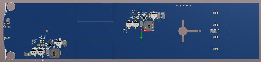
Finished up most of the placement of the components and the wiring on the board.
I will add the capability to do the "back-off" brake lights and sequential turn signals. The turn signals are arranged in 6 vertical strings of which I can control each of 2 strings separately.
The BOM cost for components alone is reaching $60 of which 1/2 of this is for the LEDs.
Attached thumbnail(s)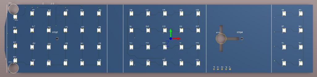
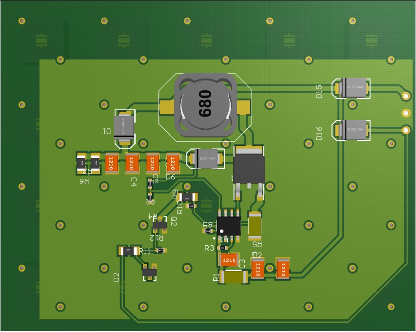
Posted by: Spoke Jan 27 2013, 02:45 PM
Here's a close up of the outside end of the board. The side marker LEDs are mounted on the edge of the board.
The circuitry is a constant current dc-dc boost converter to drive the turnsignals. This will provide constant current regardless of battery voltage which we all know varies all over the place in the 914. This converter and associated components represents about $10 cost but will give superb operation.
The outside edge of the board is cut at an angle on the top and bottom to allow the same board to be used on both sides.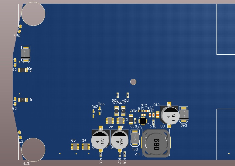
This little T cut-out is for the webbing in the lens cover. The one mounting hole is very close to the cut-out. I'm hoping to not have to trim the webbing but that wouldn't be that bad to trim the webbing a bit.
The 5 holes at the top are to solder the wires from the enclosure. I'm trying to think of a better way to connect the wiring to the board.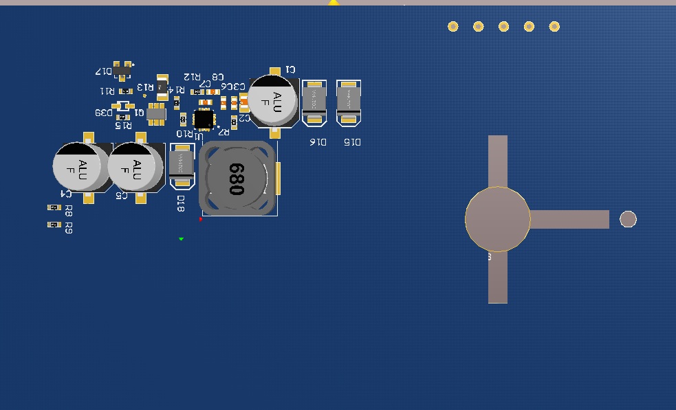
Posted by: A&PGirl Jan 27 2013, 03:16 PM
Very nice.
What kind of software are you working with?
Posted by: Cairo94507 Jan 27 2013, 03:38 PM
I definitely want these 
Posted by: gothspeed Jan 27 2013, 03:53 PM
I am in for LEDs, will they replace the entire assemblies or plug into the existing bulb sockets?
I have tried those plug in LED bulbs from FLAPS and the brake light is barely noticeable. 
So I am thinking these custom versions would be better, right ?
Posted by: Spoke Jan 27 2013, 04:40 PM
Very nice.
What kind of software are you working with?
Thanks. I'm using Altium. It's pretty powerful as you can do schematic capture and go right to PCB layout. Change in the schematic? No problem, just reload the schematic and parts removed disappear and new parts appear on the PCB.
Posted by: Spoke Jan 27 2013, 04:50 PM
I am in for LEDs, will they replace the entire assemblies or plug into the existing bulb sockets?
I have tried those plug in LED bulbs from FLAPS and the brake light is barely noticeable.
So I am thinking these custom versions would be better, right
?These will fit in the existing enclosure with the original lens. It will replace the reflectors/bulb sockets. The goal is to not have to cut any plastic or change flashers to install.
Posted by: JmuRiz Jan 27 2013, 05:15 PM
Cool stuff, there is a company that does something similar for 356s...but that's the only model they build them for.
It never hurts to have brighter lights these days
Posted by: d914 Jan 27 2013, 05:19 PM
interested
Posted by: Chris H. Jan 27 2013, 05:38 PM
Very interested..
Posted by: no1uno Jan 27 2013, 05:53 PM
interested
Posted by: A&PGirl Jan 27 2013, 06:25 PM
Very nice.
What kind of software are you working with?
Thanks. I'm using Altium. It's pretty powerful as you can do schematic capture and go right to PCB layout. Change in the schematic? No problem, just reload the schematic and parts removed disappear and new parts appear on the PCB.
Your welcome.
I'm always impressed by creative solutions to an existing problem. The software sounds like a very good setup and I'm glad it works well for you. I know how expensive CAD software can get.
I can definitely help with installation instructions and/or the hardware to install the buckets if you need me to.
Posted by: monkeyboy Jan 27 2013, 11:15 PM
Lots of those drop in LED "bulbs" are very directional. They end up being less visible on a car as low as ours.
I like this idea. Using good LED's with a wide pattern would work great.
I would be in for a set for sure.
Posted by: DEC Jan 28 2013, 01:45 AM
Lots of those drop in LED "bulbs" are very directional. They end up being less visible on a car as low as ours.
I like this idea. Using good LED's with a wide pattern would work great.
I would be in for a set for sure.
I think it is a bit more difficult as it shows......
There are lot of different LED's so you havs the choice and the
challenge to find the one which matches the requrirements.
For the back driving light and fllasherlight I use the bulbs like Mark
shows.
For brake light and rear light I use a Spider LED like this
http://www.aliexpress.com/store/product/S25-BA15D-1157-3528-40leds-5-claws-led-spider-light-car-brake-light-backup-light/107398_529717985.html
These are mutch brighter and makes a huge different between back and brake light
Posted by: ruby914 Jan 28 2013, 01:51 AM
Interested!
Posted by: Scarlet75 Jan 28 2013, 05:07 AM
My car isn't ready yet, so,
Maybe I can get a local volunteer to try them.
Scotty-In-NH Where are you?
I have installed LED bulbs in my car. I have also added cheesy chrome tape to replace my fading backing. I have a LED third brake light that is only noticeable when I step on the brakes. I agree the more LED's you have on each bulb the better I went with a company that sells them and I don't regret it. Those that went to Hershey last year have seen my brake lights.
Posted by: lagunero Jan 28 2013, 11:53 AM
Paul (smrz914) made them. I don't know how many. I funded the project and received the prototype. TonyAKAVW (electro wizard) has it now. I don't think they will be any cheaper to make but IIRC, Tony did say they are nice.
Posted by: zymurgist Jan 28 2013, 01:18 PM
Fascinating. I would be in for a set if this comes to fruition.
Posted by: Nürburg Nomad Jan 28 2013, 02:09 PM
If you're upgrading to LED's (or not, they work with regular bulbs too), you might consider a "back off light" or "taillight flasher". I know many people are concerned with getting rear-ended and protecting their precious teeners. This is usually one of the first mods I do to any motorcycle I ride regularly. The manufacturers advertise something like a 40% reduction in rear end accidents on motorcycles. Also, many newer ambulances feature a similar technology for safety reasons. If anybody wants more info on these I have a large variety of models I can order from at a decent discount as well.
This video is one of the better examples I can find. Most videos look wrong because of frame rates on the cameras. Some modules allow you to fine tune the flash rate, number of flashes, and even integrate turn signals.
https://www.youtube.com/watch?v=e368R4ttjCE
Agreed, I can vouch for the effectiveness of the "Back-Off XP" which I installed on my 914 shortly after I obtained the car a few years ago. Vehicles give me a measurable increase in following distance under braking, which started as soon as I wired in the weather proof module inside the car behind the center of the backpad. If I understand correctly the "Back-Off XP" is the original/best unit that most motorcyclists use? My LED 3rd brake light will utilize the 5-flashes before steady illumination function too once I have it installed. The flashing is certainly more effective with LED taillights so I look forward to see what sort of 914-specific LED taillights develop in the coming year?
Buy it here: http://www.amazon.com/Signal-Dynamics-Brake-Module-1004/dp/B001F85OUM
Posted by: Jgilliam914 Jan 28 2013, 04:11 PM
If you build them we will buy!!
Every time I find myself behind a newer car with LED's I find myself staring at them. I feel they are one of the best new safety features on any new vehicle
Posted by: Spoke Jan 28 2013, 04:58 PM
Paul (smrz914) made them. I don't know how many. I funded the project and received the prototype. TonyAKAVW (electro wizard) has it now. I don't think they will be any cheaper to make but IIRC, Tony did say they are nice.
Do you have any information on which LEDs were used or how they were powered?
I have no pride WRT copying something that works or improving on a previous idea.
PM sent.
Posted by: tscrihfield Jan 28 2013, 05:15 PM
Spoke let me know if you need any help on this. I deal with these everyday and I have very good connections with all of my Board suppliers. If the order is small enough, I can probably have these boards ran for free or nearly free. I buy close to 5 million in bare boards each year and have good reputations with PCB houses. I would love to help you get the cost down as I am interested in these as well.
I can probably get the LEDs at cost as well. I can run them through a personal PO to Avnet, Digikey or TTI. Whichever has a better deal...
Thomas
Posted by: Spoke Jan 28 2013, 09:35 PM
Spoke let me know if you need any help on this. I deal with these everyday and I have very good connections with all of my Board suppliers. If the order is small enough, I can probably have these boards ran for free or nearly free. I buy close to 5 million in bare boards each year and have good reputations with PCB houses. I would love to help you get the cost down as I am interested in these as well.
I can probably get the LEDs at cost as well. I can run them through a personal PO to Avnet, Digikey or TTI. Whichever has a better deal...
Thomas
Thanks Thomas, I'll keep that in mind.
The main issue right now is to find an LED which is efficient enough to give the brightness I'm looking for and somewhat affordable.
Any suggestions of an LED would be appreciated.
The first one I tried didn't give the output I was looking for. Here's the info at Digikey:
http://www.digikey.com/product-detail/en/MLBAWT-A1-0000-000VE7/MLBAWT-A1-0000-000VE7CT-ND/2509900
I found an OSRAM LED with twice as much output. I'll get some samples of this one and give it a try.
http://www.digikey.com/product-detail/en/GW%20DASPA1.EC-HPHR-5H7I-1/475-2996-1-ND/3175388
Posted by: charliew Jan 28 2013, 11:14 PM
I am also interested in these lights. I have a radiance tail light on my harley and it had the sequential turn leds with the flashing brake and it was bright.
Posted by: Harpo Jan 29 2013, 05:42 AM
Very interested. Count me in
David
Posted by: Spoke Jan 29 2013, 11:52 AM
Here's the test fixture that I've used to evaluate the LEDs.
These LEDs are bright as hell but still not bright enough for this application.
Attached thumbnail(s)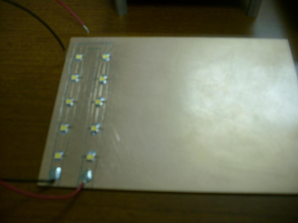
Posted by: Spoke Jan 29 2013, 11:54 AM
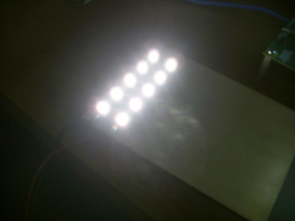
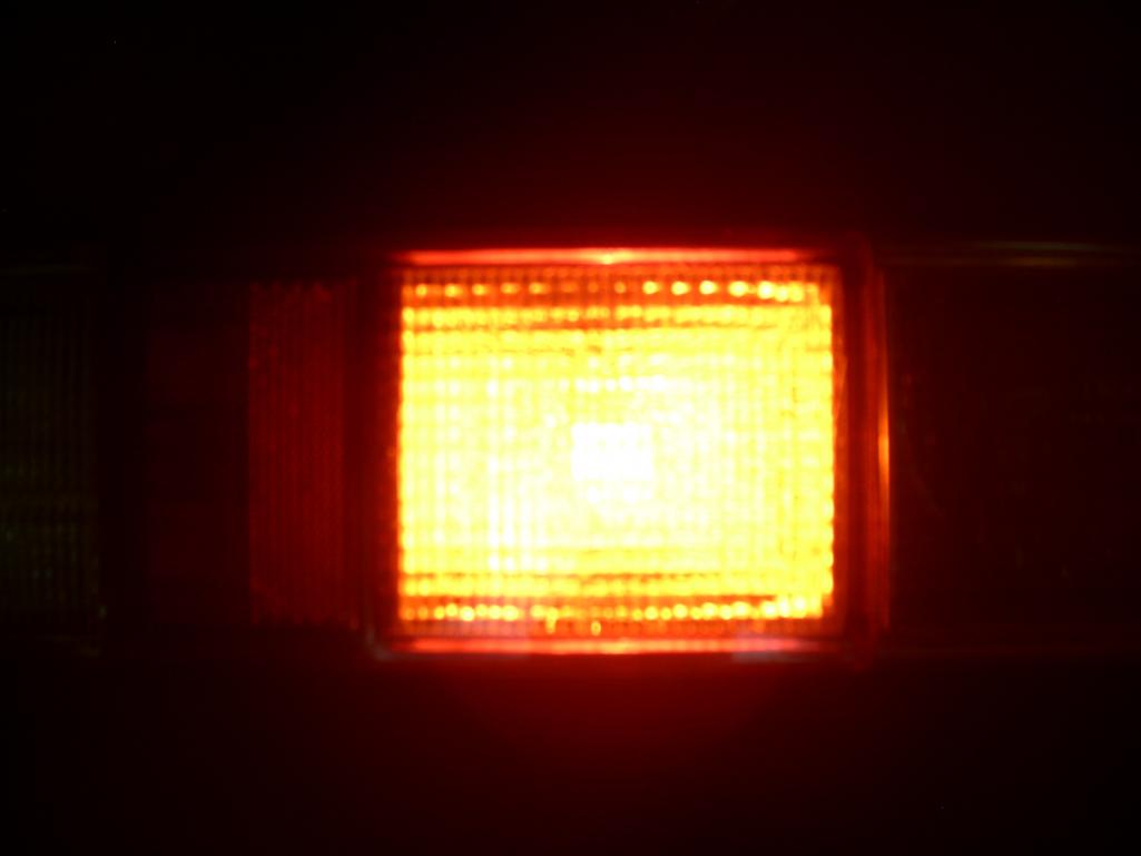
Here's the comparison with the existing brake light @ 13.6V vs the LED. Keep in mind that these are only 1/2 of the LEDs that would be used for the brake lights.
Attached thumbnail(s)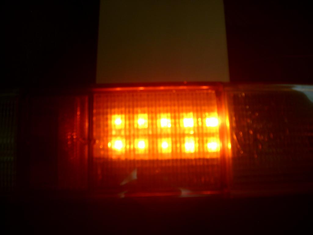
Posted by: Spoke Jan 29 2013, 11:58 AM
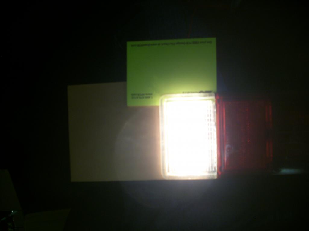
The standard backup light is 25W which is slightly more power than the brake light at 21W.
Here the difference is not so obvious. The next LEDs that I am looking at are about 1.5x brighter.
Attached thumbnail(s)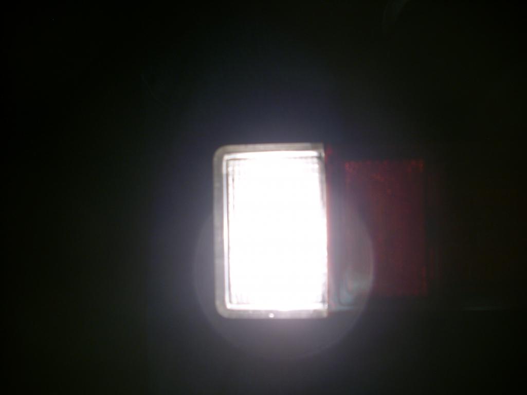
Posted by: gothspeed Jan 29 2013, 12:08 PM
I am in for LEDs, will they replace the entire assemblies or plug into the existing bulb sockets?
I have tried those plug in LED bulbs from FLAPS and the brake light is barely noticeable.
So I am thinking these custom versions would be better, right
?These will fit in the existing enclosure with the original lens. It will replace the reflectors/bulb sockets. The goal is to not have to cut any plastic or change flashers to install.
Cool! Thanks for the reponse. Looking at the pictures above, it appears these are gonna turn out very nice. Also in my opinion, the brighter the brake lights the better
Another great thing about this upgrade, is the lower current draw of the LEDs should allow more current for ignition and stereo components ....

Posted by: HarveyH Jan 29 2013, 12:17 PM
You might consider doing your testing with red LED's. The white LED's produce light in many wavelenghts. The red lens filters out all of the light except for the red wavelengths. If you start with an LED of a given wattage a specific color LED you should get more light in the wavelengths you need.
From the Superbriteleds page: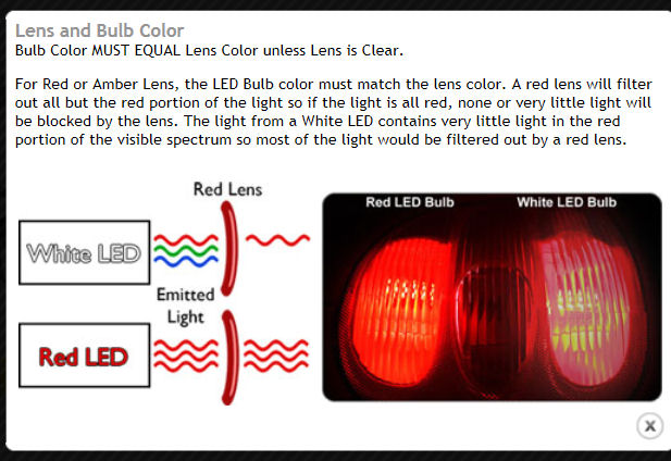
Harvey
Posted by: 7TPorsh Jan 29 2013, 12:25 PM
You might consider doing your testing with red LED's. The white LED's produce light in many wavelenghts. The red lens filters out all of the light except for the red wavelengths. If you start with an LED of a given wattage a specific color LED you should get more light in the wavelengths you need.
From the Superbriteleds page:
Harvey
Always wondered about this. Does this mean the same when using regular bulbs?
If I use red incandescent bulbs; are they better than clear?
Posted by: zymurgist Jan 29 2013, 12:44 PM
Does that mean two different specs, one for US lenses and one for Euro lenses?
Posted by: HarveyH Jan 29 2013, 02:09 PM
7TPorsh:
I would think that most standard incandescent bulbs produce a wide range of wavelenghts and the red envelope does the filtering to remove unwanted colors producing the red light. While the red lens will pass most of the red light, there will still be some additional filtering losses so you would probably be better using a clear bulb and do all of the filtering with the lens. I don't believe most LED's are truly monochromatic (like a laser), but rather they produce a variety of wavelengths within a fairly narrow band. {red(ish) or blue(ish) or.....} Anybody know about this???
Zymurgist:
From what I think you're asking: optimally you would use white LED's for the backup light portion of the taillights and red LED's for the red portion. For the Euro lenses you would also need amber LED's for that specific portion of the lens. Also, amber LED's for the US spec front lenses and marker lights.
Harvey
Posted by: Madswede Jan 29 2013, 03:28 PM
7TPorsh:
I would think that most standard incandescent bulbs produce a wide range of wavelenghts and the red envelope does the filtering to remove unwanted colors producing the red light. While the red lens will pass most of the red light, there will still be some additional filtering losses so you would probably be better using a clear bulb and do all of the filtering with the lens. I don't believe most LED's are truly monochromatic (like a laser), but rather they produce a variety of wavelengths within a fairly narrow band. {red(ish) or blue(ish) or.....} Anybody know about this???
Oddly enough I was just researching LEDs a bit ago. Wiki has a decent summary on the technology behind how LEDs work, and to summarize it all up, it would seem you're exactly correct in saying that LEDs emit light in a relatively narrow range of wavelengths (colors). It seems they may or may not be totally monochromatic depending on the semiconductor material and doping materials used (there is such a thing as a diode laser, apparently). I'm certain you're also correct about incandescent bulbs emitting a wide range (more or less white light) of wavelengths.
In contrast, LEDs typically emit light in a certain color (i.e. not white) due to how the light comes about from the electrons' behavior in the diode's doped semiconducting material. Hence, LEDs do not typically use filters at all unless for some special application or circumstance. It's tricky to get white light from an LED and while it is of course possible, there are several ways of doing it (including using more than one actual LED in each "light" assembly).
Posted by: zymurgist Jan 29 2013, 05:49 PM
From what I think you're asking: optimally you would use white LED's for the backup light portion of the taillights and red LED's for the red portion. For the Euro lenses you would also need amber LED's for that specific portion of the lens. Also, amber LED's for the US spec front lenses and marker lights.
Exactly!
Posted by: cconcepcion Jan 29 2013, 06:25 PM
I'm interested in a set....
Posted by: Type 47 Jan 29 2013, 06:34 PM
interested
Posted by: Cairo94507 Jan 29 2013, 06:50 PM
This project is definitely heading in the right direction. I think this could be one of the most significant safety improvements one could make to their car to preserve it for the future.
Posted by: mrbubblehead Jan 29 2013, 06:52 PM

Posted by: PThompson509 Jan 29 2013, 10:26 PM
+1
I've got a LED strip just under the roof, attached to the chrome - makes for a great 3rd brake light - easy to attach too.
Once this comes out I'm VERY interested in buying a set to replace the sad lights behind the plastic. Please count me in.
Cheers!
Posted by: StratPlayer Jan 30 2013, 04:10 PM
Interested 
Posted by: montoya 73 2.0 Jan 30 2013, 04:18 PM
Would be interested if the LED's are of the correct lens color & sequential turn signals.
Posted by: steuspeed Jan 30 2013, 04:28 PM
For a long time blue LEDs did not exist, so it is not a matter of adding a color filter. Once blue was invented they started showing up on all kinds of products and enabled RGB combinations (pixels) to create a wide range of colors.
Posted by: Chris H. Jan 30 2013, 04:40 PM
This project is definitely heading in the right direction. I think this could be one of the most significant safety improvements one could make to their car to preserve it for the future.
most teeners get hit from behind these days. At least in the accidents where the other party is at fault. I remember a beautiful Irish Green '71 6er that I wanted to buy from the board...someone else bought it and got immediately HAMMERED in a rear-ender. Not his fault at all IIRC. We're too low not to have bright tail lights and a 3rd brake light any more. Thanks for the hard work on this.
Posted by: a914622 Jan 30 2013, 05:21 PM
So Volvo uses a diffuser that looks like a half a magnifying glass between the led and lens. I will try to post some pics. The red leds they use are not all that bright, but stack the assmbaly together and WOW bright brake light. Maybe a diffuser lens / red lad would give you the pop your looking for?
jcl
Posted by: Spoke Jan 30 2013, 10:22 PM
I'm looking for more powerful LEDs for my next test. Also looking for a red LED for the tail/brake lights. These have to be as bright or brighter than normal brake lights.
These LEDs are not cheap as it looks like the LEDs will cost over $1 a piece.
Time to order the LEDs below.
http://www.digikey.com/product-detail/en/MLERED-A1-0000-000V01/MLERED-A1-0000-000V01CT-ND/3074417
http://www.digikey.com/product-detail/en/MX3AWT-A1-R250-000C51/MX3AWT-A1-R250-000C51CT-ND/2356706
Posted by: montoya 73 2.0 Jan 30 2013, 11:59 PM
Have you looked at LumiLEDs?
http://www.philipslumileds.com/lighting-solutions/lighting-applications/automotive-lighting
http://www.oznium.com/four-chip-led
http://www.ledssuperbright.com/100-3mm-piranha-super-flux-wide-led-p-228/gclid/CK28sJP6kbUCFWPhQgod72MAQA
http://www.allelectronics.com/make-a-store/item/LED-912/SUPER-BRIGHT-RED-SUPERFLUX-LED/1.html
Posted by: a914622 Jan 31 2013, 07:33 PM
The super flux ones look just like the volvo 3rd brake light leds. I think the little dome on the top acts like a focus or diffuser?
jcl
Posted by: montoya 73 2.0 Jan 31 2013, 08:00 PM
My mom worked at LumiLEDS several years ago. She gave me a few of those SuperFlux LED's and they are bright as hell! I believe they are meant for automotive use.
Posted by: Spoke Feb 1 2013, 11:22 AM
I checked out the LumiLEDs. They look pretty good. I will get some Amber and White ones.
I found Red LEDs through digikey to be more cost efficient than through Future who carries LumiLEDs.
The plan now is to put red LEDs under the red brake lens and amber under the amber turnsignal lens.
I have orders some more LEDs to try out. I want to make sure that whichever LED is chosen it will be as bright or brighter than the existing bulbs.
http://www.digikey.com/product-detail/en/XBDRED-00-0000-000000701/XBDRED-00-0000-000000701CT-ND/3641974
http://www.digikey.com/product-detail/en/MLERED-A1-0000-000V01/MLERED-A1-0000-000V01CT-ND/3074417
http://www.digikey.com/product-detail/en/GW%20DASPA1.EC-HPHR-5H7I-1/475-2996-1-ND/3175388
http://www.digikey.com/product-detail/en/MLCAWT-A1-0000-000XE3/MLCAWT-A1-0000-000XE3CT-ND/3074390
http://www.futureelectronics.com/en/technologies/semiconductors/lighting-solutions/high-power-led-emitters/colour/Pages/8022837-LXZ1-PL01.aspx?IM=0&IT=False
http://www.futureelectronics.com/en/technologies/semiconductors/lighting-solutions/high-power-led-emitters/white/Pages/6022836-LXZ1-4070.aspx?IM=0&IT=False
Posted by: zymurgist Feb 1 2013, 02:14 PM
Thanks for putting this together, Spoke. I bet you will sell a lot of them... 
Posted by: Spoke Feb 1 2013, 09:15 PM
The test I did with 10 LEDs putting out about 40LM each didn't achieve the brightness I am looking for although they were bright as hell.
One item that is designed into all LED lighting is proper lense and/or reflector designed for the LEDs. This is true on all factory-designed LED lights.
So I've been looking into reflectors for LEDs and ran across the following thread on CandlePoweredForum discussing LED brake and tail lights.
I don't know any of these guys nor do I know their backgrounds but they sound quite knowledgeable about automotive lighting and LEDs.
Seems all of the "experts" on this thread indicate that the drop-in LED replacement bulbs are not very good and may even be illegal to replace filament bulbs with LED drop-in's in tail and brake light fixtures in some states.
They bring up good points about brake/tail light modifications and ramifications concerning liability if one is involved in an accident.
http://www.candlepowerforums.com/vb/showthread.php?295517-Red-filter-%28tail-light-lens%29-red-or-white-LED
In short, this LED implementation that I am doing could be illegal since it involves modifying a safety feature on an automobile. If I sell this to someone and they have an accident or get pulled over for having illegal lights, would I be liable? Maybe I'd have to state "for off-road applications only".
Here's another thread on LED automotive lighting and lenses.
http://www.photonics.com/Article.aspx?AID=27521
Posted by: charliew Feb 1 2013, 09:33 PM
Many years ago I modified a 69 mustang rear tail light lens and found out it needed so much reflector lens to pass tx inspection. I bet if you make a light setup and it's brighter than the original lights it will be good. I would not worry about it on my car but you how lawyers are. Off road only is also ok for me.
I tried those led replacement bulbs in a 86 blazer and they were brighter but didn't last very long for some reason.
Posted by: Spoke Feb 1 2013, 10:22 PM
For those thinking about changing to LED bulb replacements, research carefully. This guy tried them on his bike and didn't like the results.
http://www.fjrforum.com/forum/index.php?showtopic=125167
Posted by: Cairo94507 Feb 1 2013, 10:50 PM
I would be perfectly happy for my tail light kit to come with a big sticker on the box that said "FOR OFF ROAD USE ONLY". I just really want this project to be a part of my build.
Posted by: euro911 Feb 1 2013, 11:04 PM
When I was involved with a colleague manufacturing custom cycle chassis, suspensions systems and other components, they were sold with a disclaimer stating "for show use only". Liability insurance quotes were astronomical 
Lighting systems must meet DOT requirements, but there are numerous aftermarket lighting components on the market, as we all see on the road every day. I'm curious if they have a disclaimer included in their instructions 
Posted by: Harpo Feb 2 2013, 08:21 AM
Yea, I'm OK with "for off road use only". Anything to keep this project moving forward.
Thanks for running with this.
DAvid
Posted by: monkeyboy Feb 4 2013, 10:55 AM
Obviously I would only be using these on my track car.
Posted by: Chris H. Feb 5 2013, 11:05 AM
OK stupid question... how about finding a newer car with an existing LED setup that has a pattern similar to what we need? Could that be used as a starting point and modify/add from there? Too expensive? Maybe an American car that has plenty in the bone yards? I'm a complete novice on this....just popped in my head.
Posted by: Bartlett 914 Feb 5 2013, 05:04 PM
I like this project and I hope you are able to follow through with it.
I think I would try and locate a light meter. This judging by comparison is not the best idea. Photographers use meters to get the best results. It shouldn't be too difficult to locate a reasonably priced meter.
Posted by: Spoke Feb 6 2013, 11:57 AM
OK stupid question... how about finding a newer car with an existing LED setup that has a pattern similar to what we need? Could that be used as a starting point and modify/add from there? Too expensive? Maybe an American car that has plenty in the bone yards? I'm a complete novice on this....just popped in my head.
The issue finding a late model car with working LED tail lights is that the tail lights would command a good bit of coin as replacement parts.
I got more LED samples and mounted them on my test board.
I have more powerful white LEDs as well as several red and amber LEDs for brake and turn signals. I will be checking these out over the weekend.
Attached thumbnail(s)
Posted by: gothspeed Feb 6 2013, 12:30 PM
Awesome!!! I hope this project comes through, so I can just buy them, instead of making my own
Posted by: Chris H. Feb 6 2013, 02:12 PM
OK stupid question... how about finding a newer car with an existing LED setup that has a pattern similar to what we need? Could that be used as a starting point and modify/add from there? Too expensive? Maybe an American car that has plenty in the bone yards? I'm a complete novice on this....just popped in my head.
The issue finding a late model car with working LED tail lights is that the tail lights would command a good bit of coin as replacement parts.
Ah, got it...see I knew it was a dumb question!

Glad you started this thread before I bought LED bulbs...was just about to pull the trigger. I'm in for sure on these.
Posted by: Spoke Feb 8 2013, 10:32 AM
The more I see LEDs on vehicles the more I'm convinced I will need some type of reflector to channel the light. Here's one I found online that looks like it would work.
http://www.aliexpress.com/item/20mm-High-Power-LED-Lens-120-degrees-1W-3W-Reflector-Collimator/471360183.html
Posted by: kg6dxn Feb 8 2013, 06:56 PM
The more I see LEDs on vehicles the more I'm convinced I will need some type of reflector to channel the light. Here's one I found online that looks like it would work.
http://www.aliexpress.com/item/20mm-High-Power-LED-Lens-120-degrees-1W-3W-Reflector-Collimator/471360183.html
Try a piece of clear acrylic. Sand blast one side. It should diffuse the light enough.
Posted by: Spoke Feb 9 2013, 10:04 PM
I started testing the next batch of LED samples looking for some more efficient LEDs. Also doing red, amber, and white LEDs.
To get higher lumens, got to go to LEDs with higher current capability. The one in this post is a red LED with test lumen of 71lm @ 350mA and max 170lm @ 1Amp.
These suckers are BRIGHT! I quickly realized when testing these that viewing them with my eyes is dangerous. I was running 150ma through 5 of them and I would estimate that they are about as bright as my current filament brake light bulb. I plan to use 20 of these.
So for this testing, I have to be careful not to look at them at any angle. I put my hand on them and I swear I can see my bones. 
http://www.digikey.com/product-detail/en/XBDRED-00-0000-000000701/XBDRED-00-0000-000000701CT-ND/3641974
Here's a pic about 6 feet away from the LEDs at about a 90 degree angle with no lights on. 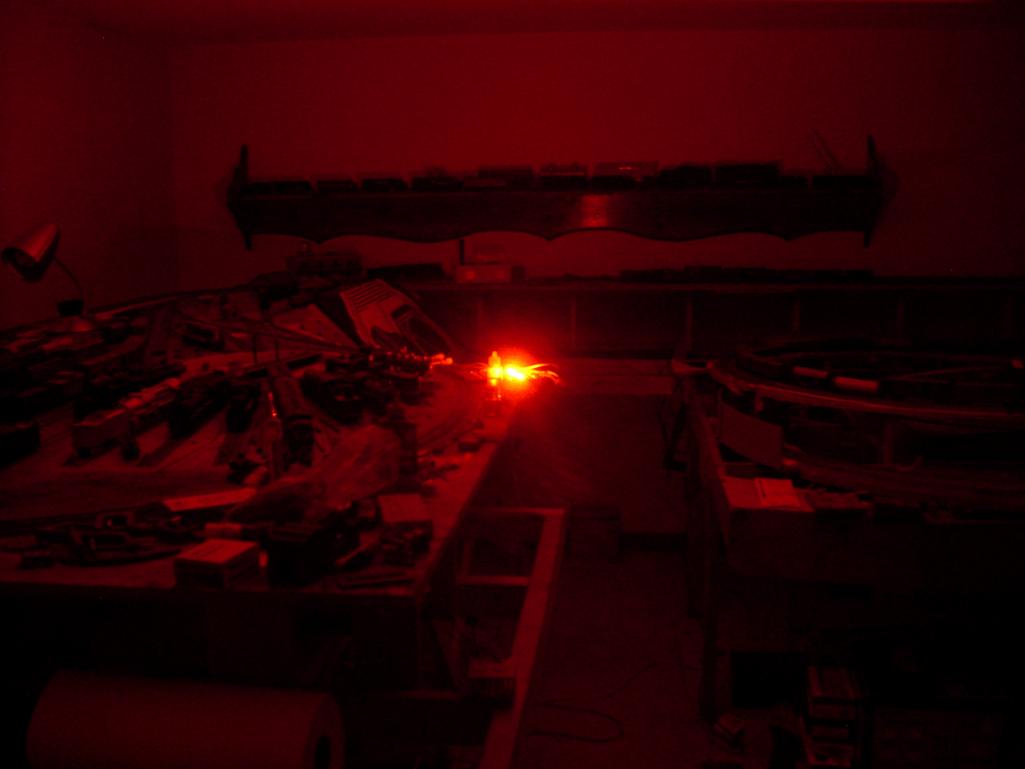
Red LEDs viewed through the brake lens. Being only 5 LEDs. With 20 LEDs I will have no issue with brightness. After about 10 minutes at this intensity, the temperature of the LEDs is barely above ambient.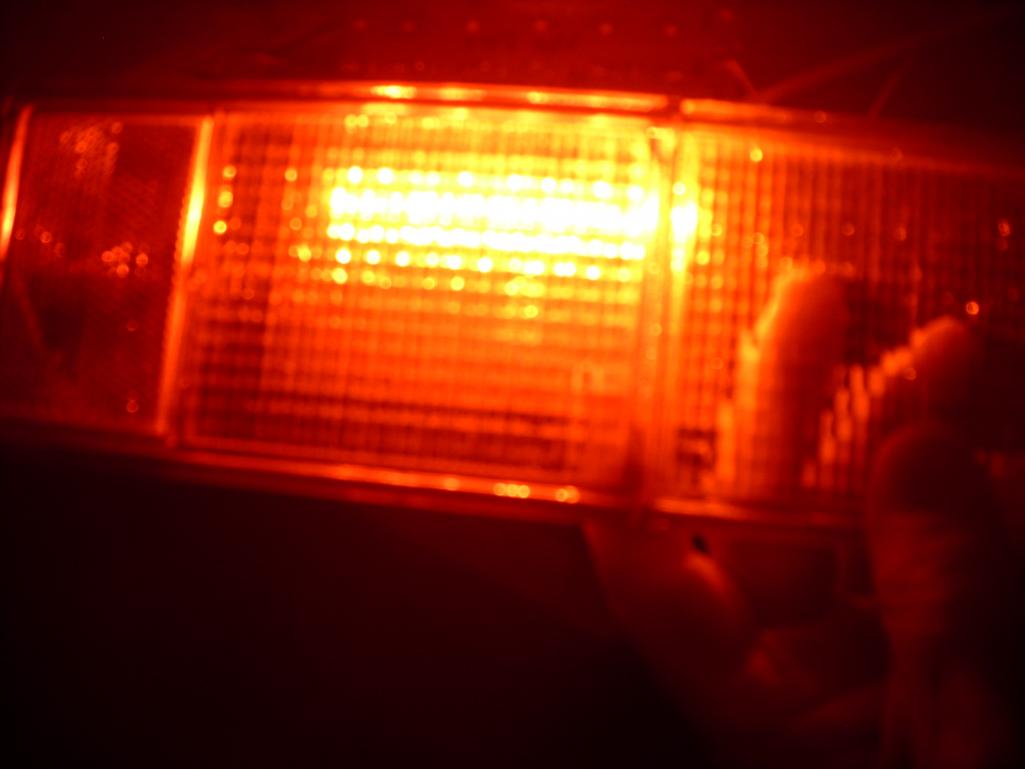
Posted by: montoya 73 2.0 Feb 9 2013, 10:35 PM
so far!!!
Posted by: euro911 Feb 9 2013, 11:09 PM
What will the total current draw be for a complete set (both tail lights)?
What is the total current draw of OEM incandescent bulbs (both tail lights)?
Posted by: mrbubblehead Feb 10 2013, 12:41 AM
Oh hell ya spoke. I think those are the best so far. Looks like you found the answer. Now just get em into production. 
Posted by: Cairo94507 Feb 10 2013, 07:25 AM
Making nice progress. I really like the way this going.
Posted by: banger Feb 10 2013, 11:56 AM
After looking at your board, you might want to move the DC/DC converters to the top of the board. This will make it much easier to manufacture if you decide to have the board stuffing done by machine. Also if you buy LED's by the reel, the price is much cheaper. I have a PCB manufacturing line at my office, if you need to have boards stuffed some time.
Posted by: a914622 Feb 10 2013, 02:47 PM
ok so i got around to getting some pics of the volvo 3rd brake set up. The first pic is crappy but the bright part is magnify piece in place the not so bright are just the leds.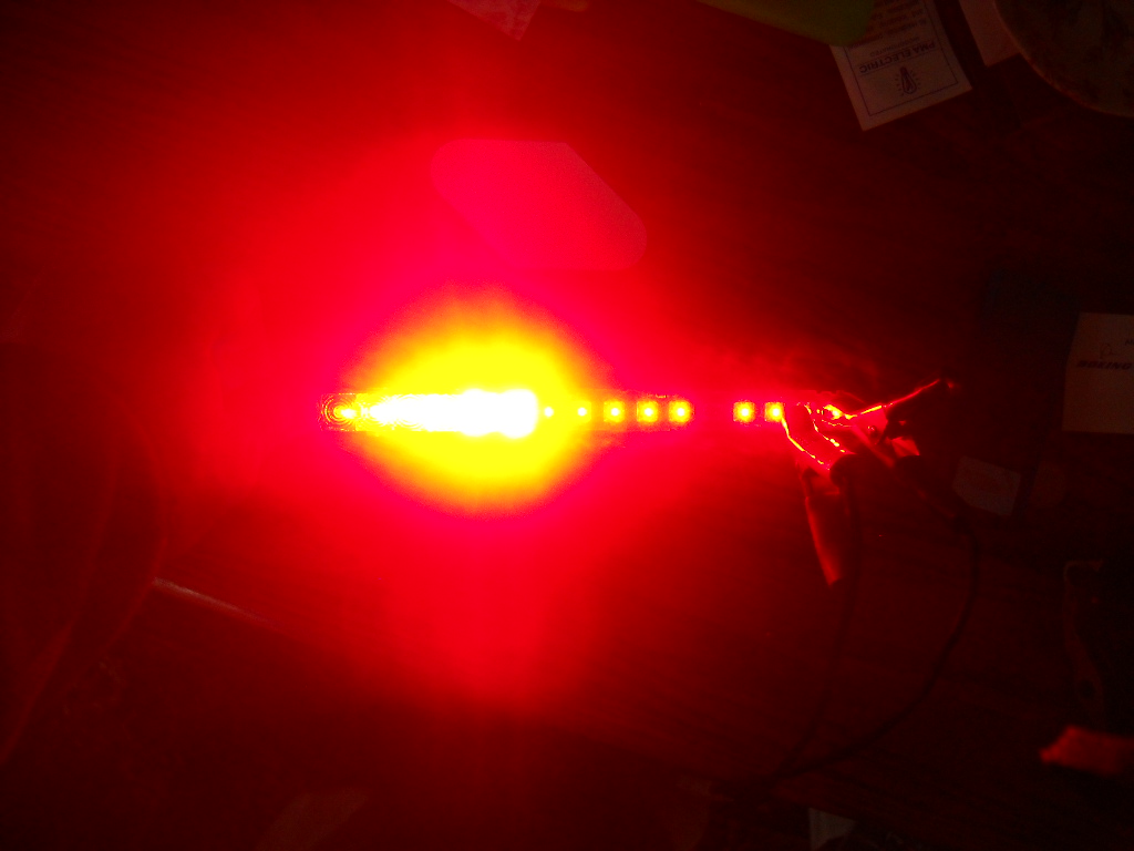
second is a side shot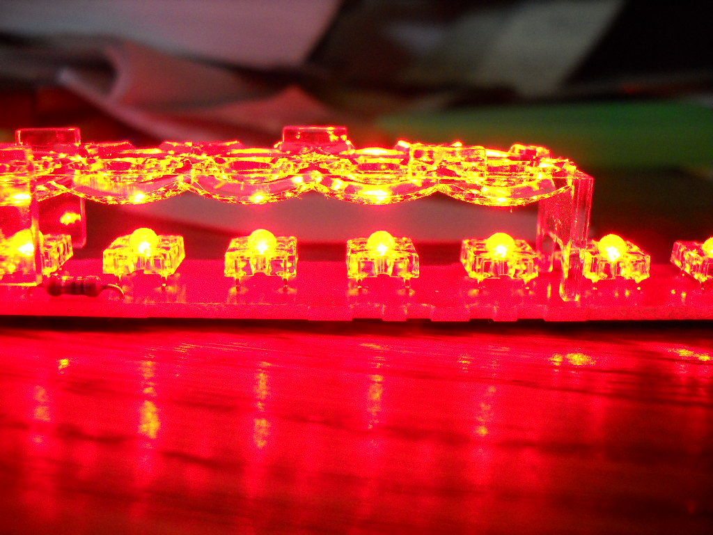
And then the diffuser lens lifted so you can see it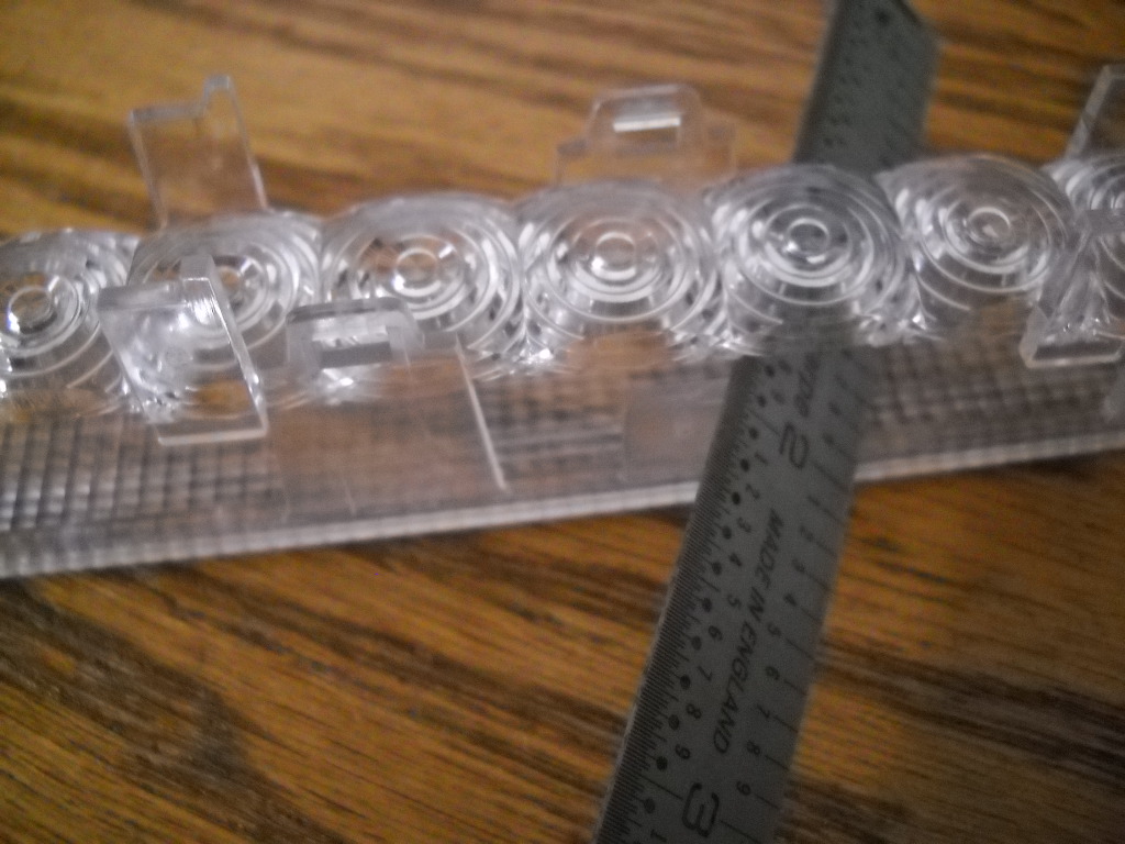
So maybe brighter leds are not the answer? Are there any "focuser" lenses out there that could be added to the board end of things?
The other car tail light leds i was looking at had a cup around the led. It was the old flashlight idea. Small light but the reflective dia is bigger/brighter.
just giving input.
jcl
Posted by: Spoke Feb 10 2013, 05:42 PM
ok so i got around to getting some pics of the volvo 3rd brake set up. The first pic is crappy but the bright part is magnify piece in place the not so bright are just the leds.
second is a side shot
And then the diffuser lens lifted so you can see it
So maybe brighter leds are not the answer? Are there any "focuser" lenses out there that could be added to the board end of things?
The other car tail light leds i was looking at had a cup around the led. It was the old flashlight idea. Small light but the reflective dia is bigger/brighter.
just giving input.
jcl
Thanks for the visuals. The lenses are an important part of the LED lights. I think pretty much all LED lights have some type of lens or reflector to focus or diffuse the light as needed for the application.
Posted by: mrholland2 Feb 10 2013, 09:08 PM
I'd be interested in a Euro tail light spec set.
Next, can someone do something to modify the fog lights to add a halo driving light? I'd be interested in that.
I'm relocating to the South Bay so I'll be driving the 914 alot more and want it visible day or night!!
Sean
Posted by: Spoke Feb 11 2013, 12:16 PM
What will the total current draw be for a complete set (both tail lights)?
What is the total current draw of OEM incandescent bulbs (both tail lights)?
For the tail lights, the plan is 20 LED at about 50ma each. This works out to about 0.25A draw.
With brake lights on, the 20 LED will do about 200ma each or about 0.9A
The 1157 tail light is about 7W or 0.5A draw. The brake light is 21W or about 1.6A
Posted by: Spoke Feb 11 2013, 12:18 PM
After looking at your board, you might want to move the DC/DC converters to the top of the board. This will make it much easier to manufacture if you decide to have the board stuffing done by machine. Also if you buy LED's by the reel, the price is much cheaper. I have a PCB manufacturing line at my office, if you need to have boards stuffed some time.
Thanks for the offer. We'll see where this goes.
The dc/dc converters won't fit on the top of the board because of the way the LEDs are lined up. I thought about that at first and came to the conclusion that they must be on the back of the board.
Posted by: Spoke Feb 13 2013, 11:31 PM
I'm looking for an economical supply for lenses. Here's one I found for individual LEDs. I will have to get a few samples to test them out.
As with the LEDs, these in particular are not cheap at $2 per LED. 50 LED per taillight assembly starts to add up. The LEDs also are looking to be about $2 each.
I should be able to find similar lenses through Asian wholesale supply companies.
http://www.luxeonstar.com/Khatod-30-15mm-Wide-Beam-Square-Optic-p/pl126440.htm
Attached image(s)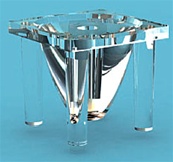
Posted by: Cairo94507 Feb 14 2013, 07:03 AM
I never expected these to be inexpensive. I am in for a set and appreciate all of the work you are doing to make these the high quality parts that our cars deserve.
Posted by: Chris H. Feb 14 2013, 09:18 AM
I'm in for a set as well regardless. There's nothing worse than seeing a car bearing down on you in the rear view mirror an wondering if the driver sees your brake lights.
Posted by: Spoke Feb 20 2013, 09:38 PM
I've ordered some sample reflectors from Future Electronics. They have good prices and seem to have stock in hand.
I stayed with a tight beam angle 12 to 18 degrees assuming the light needs to be focused behind the car as much as possible.
I should have these in a few days then I'll do some testing to see which works best.
http://www.futurelightingsolutions.com/en/Technologies/Semiconductors/Lighting-Solutions/Optics/Single-LED-Optics/Pages/6012245-GLVA1BS01H.aspx?ManufacturerName=GENERAL-LUMINAIRE&isFLS=true&IM=0 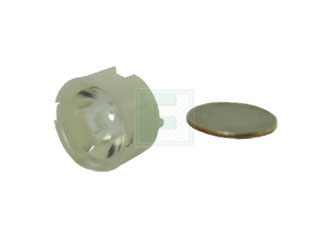
http://www.futurelightingsolutions.com/en/Technologies/Semiconductors/Lighting-Solutions/Optics/Single-LED-Optics/Pages/6053664-170-147.aspx?ManufacturerName=POLYMER-OPTICS&isFLS=true&IM=0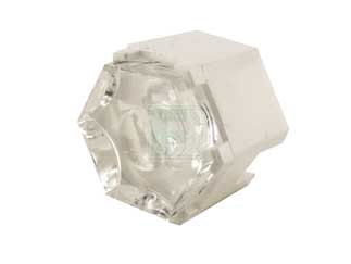
http://www.futurelightingsolutions.com/en/Technologies/Semiconductors/Lighting-Solutions/Optics/Single-LED-Optics/Pages/6374474-10412.aspx?ManufacturerName=CARCLO-OPTICS&isFLS=true&IM=0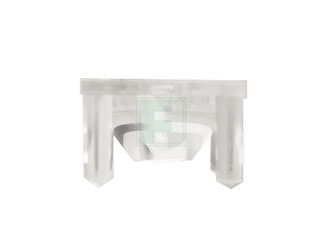
Posted by: Cairo94507 Feb 20 2013, 09:54 PM
Great and thanks for the update.
Posted by: racerbvd Feb 20 2013, 10:59 PM
I'm looking for an economical supply for lenses. Here's one I found for individual LEDs. I will have to get a few samples to test them out.
As with the LEDs, these in particular are not cheap at $2 per LED. 50 LED per taillight assembly starts to add up. The LEDs also are looking to be about $2 each.
I should be able to find similar lenses through Asian wholesale supply companies.
http://www.luxeonstar.com/Khatod-30-15mm-Wide-Beam-Square-Optic-p/pl126440.htm
I might have a contact for you on lenses.
Posted by: Spoke Feb 27 2013, 11:59 AM
Got the lens samples in this week. 2 of the samples seem to work well.
The only issue I see at this point is the beam angle (12 and 18 degrees) may be a little too tight. These collect the light very well but produce more of a focused beam than a distributed light. I will need to put these behind the 914 lens to see the diffusion added by the 914 lens.
This first one is the Polymer Optics lens. This has a 12 degree beam angle.
I have only 3 samples shown here. This is with 200ma current through the red LEDs. At 200ma, the LEDs remain cool as ever. I've run these for 15 minutes at a time and they are just above ambient temp.
Here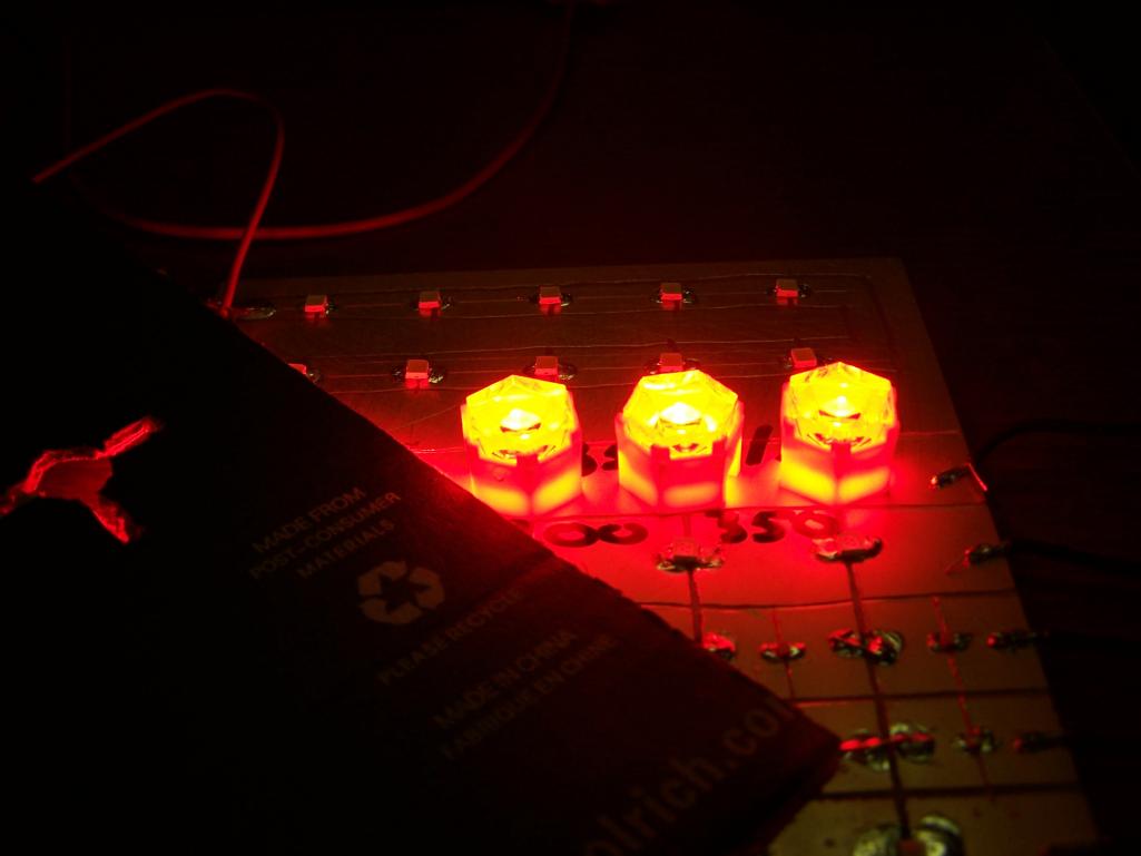
This is the pattern on the ceiling about 6 feet above my desk. The light is quite bright but as is observed, very focused. This is 3 LEDs, I'm planning to have 20 LEDs for the brake/running lights.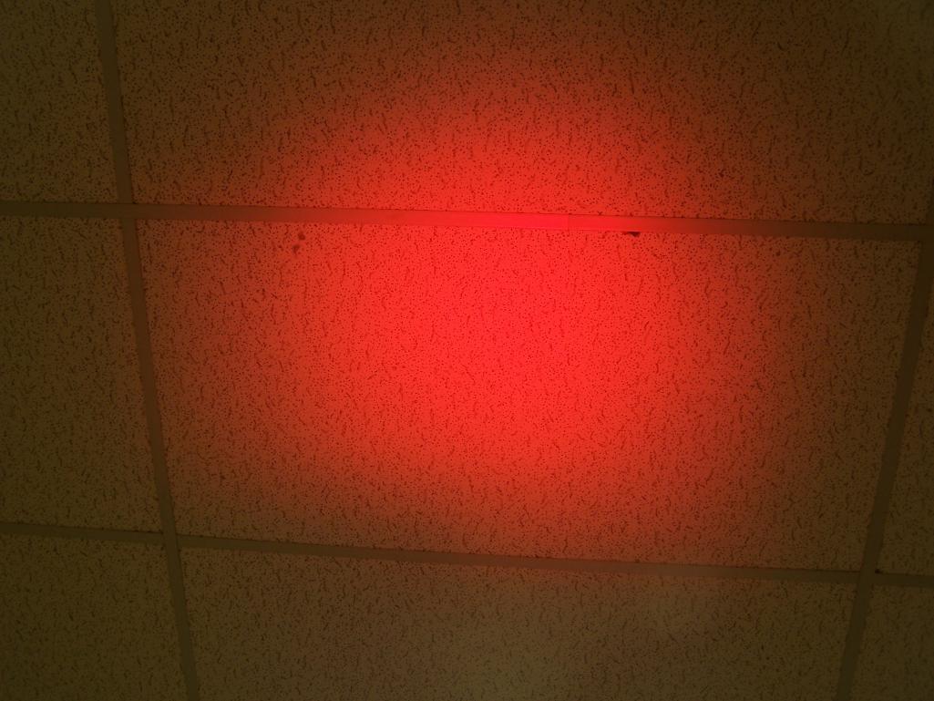
Posted by: Spoke Feb 27 2013, 12:07 PM
Next up are the Carclo lens with 18 degree beam angle.
The lenses are tiny items only 10mm across and are very efficient at focusing the light energy from the LEDs.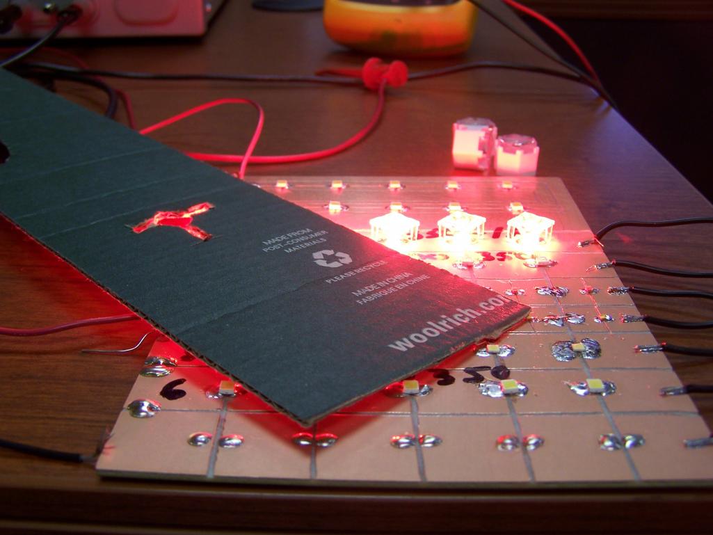
Just a comparison of the light with and without a lens. This is with 4ma of current.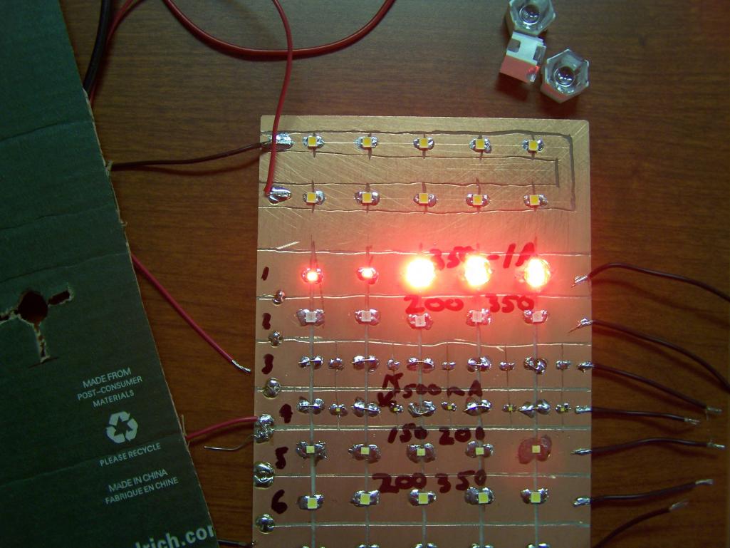
This is the pattern on the ceiling with 3 LEDs running 200ma. The beam is a bit more dispersed as compared to the Polymer Optics lens. I'm liking these ones more but I still not sure if the beam is too focused.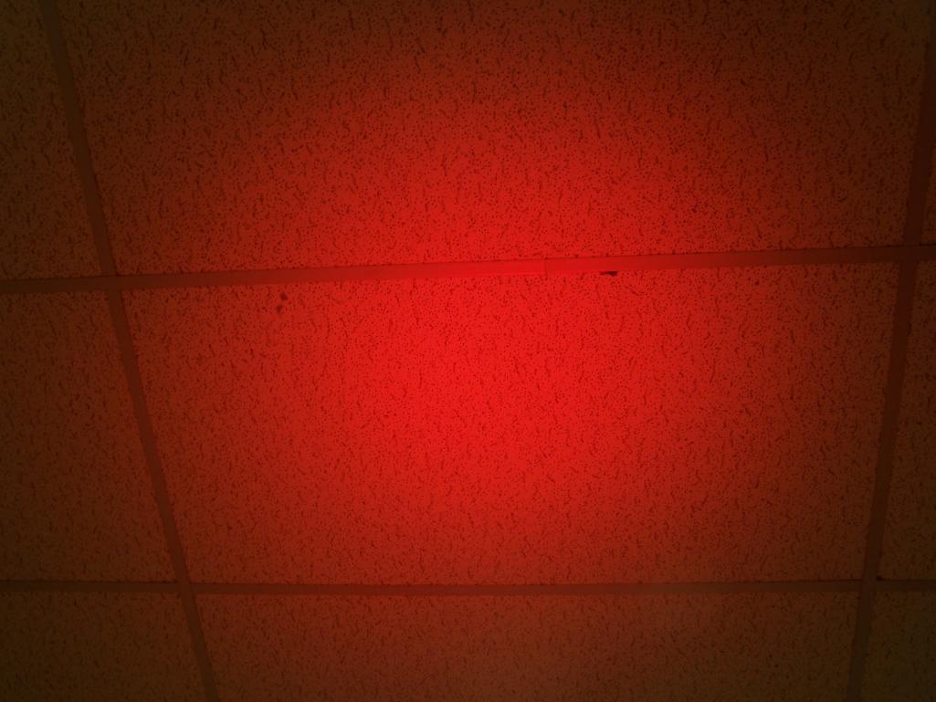
Posted by: pjhaun Feb 28 2013, 10:51 AM
Here is a YouTube video of my LED rear lights.
http://youtu.be/LppDSimnl4s
Posted by: Spoke Feb 28 2013, 11:08 AM
Here is a YouTube video of my LED rear lights.
http://youtu.be/LppDSimnl4s
Looks good. Do you have some info or thread on how you did them?
Did you have to change the blinker to run the LEDs in the back?
Posted by: pjhaun Feb 28 2013, 11:47 AM
Here is a YouTube video of my LED rear lights.
http://youtu.be/LppDSimnl4s
Looks good. Do you have some info or thread on how you did them?
Did you have to change the blinker to run the LEDs in the back?
I didn't take pictures because I didn't think it was going to work. What I did was bought an old set of rear light housings and gutted them out. Then I mounted a piece of plastic in the light housings to attach the strip LED lights. I bought the LED strip lights on Ebay. You can buy them in just about any color and length. I chose all red, but I could have put yellow for the turn signal instead of red. I did the same thing to the front turn signal housings with yellow LED strip lights. I did have to buy a new flasher that can be used both for LED lights abd standard lights.
Posted by: ScoopLV Feb 28 2013, 12:45 PM
Impressive looking lights -- I particularly like the third brake light on the targa bar.
Could you shoot a picture of it during the day?
Posted by: Chris H. Feb 28 2013, 01:59 PM
Check out the arrow indicators in the window! No one is going to miss the fact that you are turning!
Posted by: pjhaun Mar 11 2013, 03:22 PM
Impressive looking lights -- I particularly like the third brake light on the targa bar.
Could you shoot a picture of it during the day?
I shot a video of my LED tail lights today, which pretty bright outside.
http://youtu.be/HVHsN-HgFHA
Phillip J. Haun
Oak Harbor, WA.
Posted by: jhora Mar 11 2013, 06:53 PM
Nice Job Phillip...pretty darn cool!
Posted by: euro911 Mar 11 2013, 08:35 PM
Posted by: gothspeed Mar 11 2013, 10:05 PM
How is the OP Spoke doing with his LED light progress? ![popcorn[1].gif](style_emoticons/default/popcorn[1].gif)
Posted by: Spoke Mar 12 2013, 10:12 AM
How is the OP Spoke doing with his LED light progress?
I'm still moving forward. I'm looking for a more efficient amber LED. I got some samples of an OSRAM amber LED from Digikey but the damn things are red. We questioned Digikey if that was the right part and they claim the amber wavelength overlaps the red wavelength and some amber LED could look red.

All the LEDs will use the Polymer Optics lens. These will have to be glued onto the boards. The good thing about the lenses is they don't require holes and this will allow me to put circuitry behind the LEDs. Can't fit the power supplies on the same side of the LEDs so they will go on the bottom of the board.
I started designing the circuitry to provide the "back off" brake light where the brake light flashes quickly a couple of times when you hit the brake.
Also designing the turnsignal lights to be sequential. There are 6 columns of 4 turnsignal LEDs that I will turn on 2 at a time so they'll go: 2 - 4 - 6 ON.
All the flashing circuitry will be done in a CPLD.
Posted by: SLKWrx Mar 12 2013, 10:34 AM
Will there be an option to not have it be sequential? Not a huge fan of that.
Posted by: Chris H. Mar 12 2013, 11:56 AM
[
I started designing the circuitry to provide the "back off" brake light where the brake light flashes quickly a couple of times when you hit the brake.
Was just going to ask you about that. Awesome. I was behind an SUV (Kia maybe) yesterday with a flashing 3rd brake light. It was very effective.
Posted by: Spoke Mar 12 2013, 12:15 PM
Will there be an option to not have it be sequential? Not a huge fan of that.
Yeah, it is pretty simple; tie a pin high or low on the CPLD to disable.
Posted by: montoya 73 2.0 Jun 30 2013, 09:18 PM
Posted by: synackack Jul 1 2013, 08:41 AM
Doing PCB123?
I was just thinking about doing this myself - but if you're almost done, count me in for a set!
Posted by: Cairo94507 Jul 1 2013, 05:21 PM
I am really looking forward to seeing those.
Posted by: McMark Jul 1 2013, 07:14 PM
Not a fan of sequential either. When I see a Mustang with those I can't help but think, "I get it. You're turning.  "
"
But having it slightly dim on and dim off would be cool (basically emulating incandescent) for the turn signal. Fast on and fancy flash for brakes is great! Turn signals really are fine the way they are.
But regarless, really looking forward to this progress! 
Posted by: Speedmster Oct 27 2013, 09:20 AM
Spoke, how are you coming along with your LED Taillights?
I am not a fan of the flashing brake lights. I think if the brakes are being used the light should be on. I see the flashing brake lights on motorcycles a lot and sitting behind them at an intersection is annoying. Yes, I understand the point, I guess I'm a little old school these days and actually pay attention when I drive.
Posted by: veekry9 Oct 27 2013, 07:42 PM
The latest craze,all in the spirit of safety.
There are some drivers out there who need a stimulating visual clue
when driving.The coolest seq sigs of the 60's,Thunderbirds,Cougars.
The cost to produce those die-castings was enormous.
A simple application of the high intensity LEDs makes a good
argument for 21st century tech. As a replacement for the obtrusive
sidemarkers they would meet the standards.A high visibility 914
makes it a safer ride and circumvents the defense of "I didn't see the car".
Shaving the sidemarkers has been done to other vehicles for years.
The average SUV pilot needs 400+ ft to stop from 55mph depending on if
they looking.A margin of error on the side of caution would be a worthwhile
effort.You know,like,all lit up like the 4th of July.
Up the front of the targa,across the top then down the 914 curve,
unmistakeable,or spelling out the Porsche logo on the rockers,or across
the rear fascia.Man,you could even do RacingStripes down the centre.
Fun With LEDs.
Posted by: veekry9 Nov 6 2013, 11:24 AM
PJHaun Hello.
In your most recent post re the brake lights,it appears that the leds are flashing at the greatest rate on the initial push of the pedal,then slows to remain on.
I have seen a number of such flashing systems which display the opposite effect and give the viewer a proportional sense of deceleration.Flashing faster=>braking faster.
Would you consider it feasible to build a circuit that measured the brake pressure and/or g-force?
http://www.superbrightleds.com/cat/led-vehicle-replacement-bulbs/
Posted by: CptTripps Nov 6 2013, 11:45 AM
I ordered a shit-ton of LEDs off of eBay a few weeks ago. I'm planning on building custom tail lights that are patterned a lot like the new Audi tail lights. It'll be worth an experiment anyway.
Posted by: Cairo94507 Nov 6 2013, 06:54 PM
Spoke/Jerry- I am looking forward to this project hitting the classifieds so I can update the rear lighting of my Six without changing the look of the car.
Considering how much light new cars with LED's have in the rear these days, I believe that should be the goal. I want people to see the car and see it is stopping so they don't pile into it.
Aside from the LED taillight project I still plan to have a hi-mount 3rd brake light fitted into the roll bar chrome trim that is about 12-18" long.
Posted by: Spoke Nov 7 2013, 06:11 PM
I ordered a shit-ton of LEDs off of eBay a few weeks ago. I'm planning on building custom tail lights that are patterned a lot like the new Audi tail lights. It'll be worth an experiment anyway.
What LEDs did you order? Do you have a part number? I tried many different LEDs and found a great deal of difference in the output.
Posted by: Spoke Nov 7 2013, 06:21 PM
Spoke/Jerry- I am looking forward to this project hitting the classifieds so I can update the rear lighting of my Six without changing the look of the car.
Considering how much light new cars with LED's have in the rear these days, I believe that should be the goal. I want people to see the car and see it is stopping so they don't pile into it.
Aside from the LED taillight project I still plan to have a hi-mount 3rd brake light fitted into the roll bar chrome trim that is about 12-18" long.
I've been swamped at work and haven't had time to finish this up.
The last I worked on this I was looking for an efficient high output amber LED.
I got a couple from Digikey but they turned out to be more red than amber.
I'm not sure my design will be very marketable. They will be very expensive to build.
The high output LEDs that I've found cost $1.5 to $2 each. Plus each LED needs a lense to focus the light rearward. The lenses are about $1 each.
So with 20 LED for the brake, 30 LED for the turnsignal, 8 LED for the backup light, there are about 60 LED per side or 120 for both sides. Considering only the LED and lense costs, I would up to $360 not including circuitry, PCB, and assembly.
Posted by: McMark Nov 7 2013, 06:55 PM
Aren't all white LEDs cheaper? Colors might be nice, but we have white bulbs in there now... 
Posted by: Spoke Nov 7 2013, 10:50 PM
Aren't all white LEDs cheaper? Colors might be nice, but we have white bulbs in there now...
White LEDs are not always less expensive. Also they tend to have higher ON voltages (3.4V vs 2.4V for red).
I started with white LEDs and someone pointed out that red LEDs pass through red lenses more efficiently than white.
High power LEDs are generally more expensive and one issue I have is that I don't want to make this fixture and find out that the LEDs are not bright enough. I'd rather tend to have too bright than not bright enough.
Posted by: Cairo94507 Nov 8 2013, 08:04 AM
As strongly as I feel about our cars needing more light in the rear, I am willing to pay for the LED's and work as I believe these will make a big difference in accident prevention.
Posted by: CptTripps Nov 8 2013, 08:09 AM
LEDs are CHEAP no matter what. I just bought 1,000 Red, 500 White, and 500 Amber on eBay for $60 shipped.
Red: http://r.ebay.com/NEVFr3
Amber: http://r.ebay.com/bRYrcs
White: http://r.ebay.com/6XMI1E
Posted by: CptTripps Nov 8 2013, 09:59 AM
This is the layout I was thinking of doing.
It's a rough idea, and I'll have to play with it, but this is what I'm thinking right now.
I was also going to make my own lenses out of 1/4" 50% smoked plexiglass.
::: sorry for the hijack :::
Attached image(s)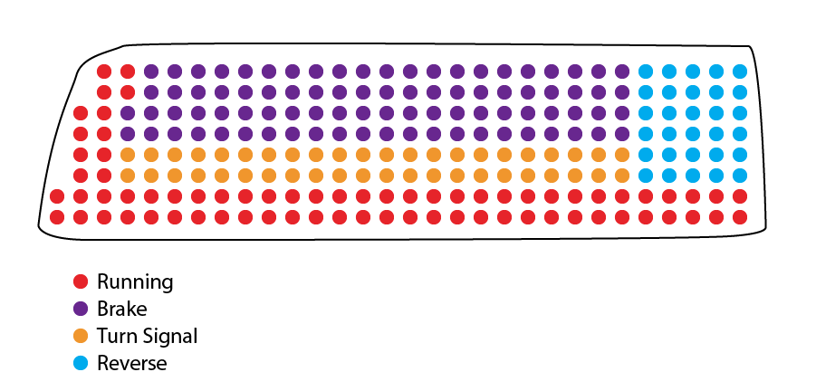
Posted by: Chris H. Nov 8 2013, 10:00 AM
Another thing for me to copy you on Douglas....NOT making my own lenses though...
Posted by: CptTripps Nov 8 2013, 10:11 AM
Oh I'm quite sure it'll end up quite different than what I'm planning right now, and it won't be anywhere NEAR as nice as what Spoke is working on.
I'm going to have a lot of hot-glue, resistors, wire, solder, and drill holes in mine! As long as it's presentable from the outside, and I can hide it in the tail-light housings, I'll be in good shape.
Posted by: veekry9 Nov 8 2013, 02:37 PM
Oh I'm quite sure it'll end up quite different than what I'm planning right now, and it won't be anywhere NEAR as nice as what Spoke is working on.
I'm going to have a lot of hot-glue, resistors, wire, solder, and drill holes in mine! As long as it's presentable from the outside, and I can hide it in the tail-light housings, I'll be in good shape.
Cap'n
a newfangled compound for custom lens making.
http://www.masterbond.com/sites/default/files/mb-slogan.png
Posted by: zymurgist Nov 10 2013, 07:49 AM
As strongly as I feel about our cars needing more light in the rear, I am willing to pay for the LED's and work as I believe these will make a big difference in accident prevention.
If this project comes to fruition, I will definitely want a set.
Yep, LEDs are still spendy. Visibility on the road is priceless.
Posted by: Harpo Nov 10 2013, 08:36 AM
Same here
DAvid
Posted by: McMark Nov 10 2013, 11:50 AM
Pricing sounds about right for a quality component. I was just looking at adding a STACK remote fuel pressure gauge to my car and it's $220 for the setup. So $350 for awesome tail lights isn't a stretch.
Posted by: zymurgist Nov 11 2013, 05:59 AM
Not an apples to apples comparison, but Harley-Davidson sells LED conversion headlight kits. The kit for the headlight only is $400, and the kit for a pair of passing lights (the 2 lights that flank the headlight) is an additional $400. I am guessing even at these prices, they have some takers.
Posted by: mikesmith Nov 20 2013, 05:04 PM
Aren't all white LEDs cheaper? Colors might be nice, but we have white bulbs in there now...
"White" is a bit misleading when it comes to LEDs; they are actually blue LEDs with a secondary phosphorescent emitter.
There's more than you care to read about here:
http://www.olympusmicro.com/primer/lightandcolor/lightsourcesintro.html
This nifty little graphic is only approximate, but it might help:
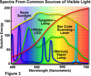
The important part is that there's not very much red in the the output of a "white" LED.
There are some pretty nice, cheap COB (chip-on-board) LED modules available in the right colours these days, if you want to make something more complicated than the direct bulb replacements that are everywhere.
= Mike
Posted by: cpavlenko Nov 25 2013, 11:51 PM
check this out. >>>>>>.
http://www.superbrightleds.com/cat/led-vehicle-replacement-bulbs/vehicle/1974-porsche---/49---/
they even have the relay for the led lights. I'm thinking...
Posted by: Spoke Nov 27 2013, 07:28 AM
The important part is that there's not very much red in the the output of a "white" LED.
I did a test with the white LEDs through the red 914 lens and the light output was not impressive. I did not have individual lenses on the LEDs which make a significant contribution to directing the LED light.
The red LEDs also have a much lower on voltage; like 2.4V vs 3.3V for white LEDs. This makes a difference when 10 LEDs are stacked together.
I've finally settled on a switching converter for the brake and turnsignals. Been looking at many different converters to find the best one for this application.
I will do a test board with just the brake/running lights, converter, and CPLD to make sure everything works together before laying out the entire assembly.
I've got the red and white LEDs chosen; just have to find some good amber LEDs for the turnsignals. I got some high power amber LEDs from Digikey but they were quite red. I've also bailed on the sequential turnsignal idea mainly for simplicity and since the turnsignal light size was not large enough to adequately discern the sequencing.
Posted by: Spoke Nov 28 2013, 12:41 AM
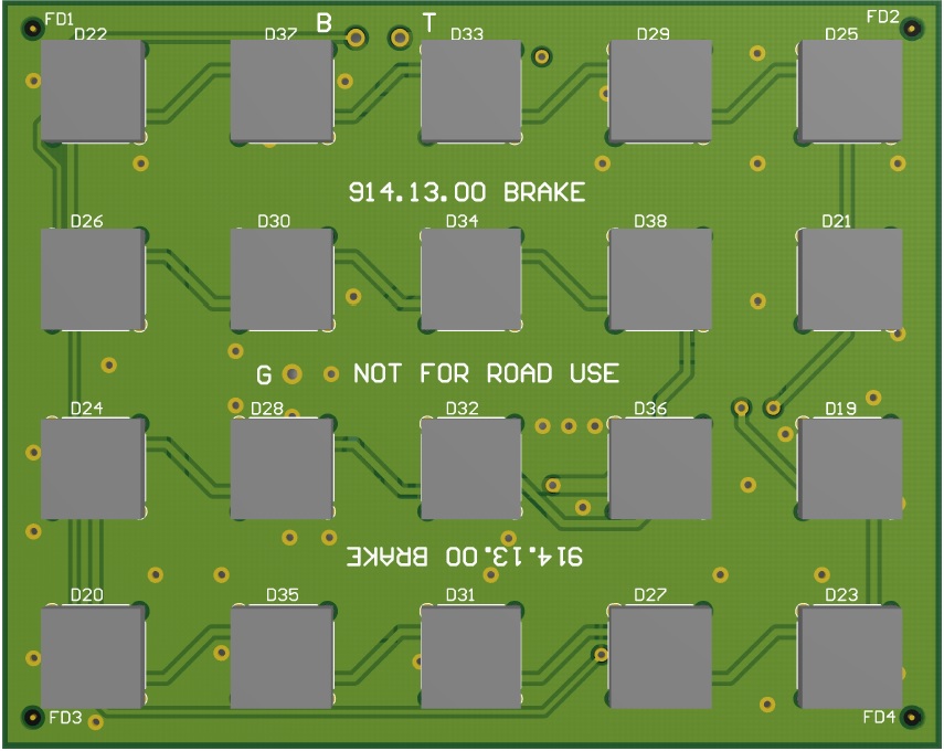
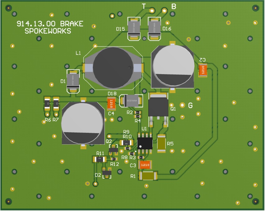
Here's the brake taillight board top and bottom views.
This board will fit inside the existing taillight frame and will get brake and taillight power from the bulb socket. Not sure how I will get power but should not be too hard.
Also need to work on securing the board. This could be as simple as silicon caulk.
I removed all leading edge flashing from the brake light for simplicity.
The big gray looking structures on the top are the LED lenses, not the LEDs. The lenses are 9x9mm.
I'll use this board as a test fixture for now but it could remain in the car for the long term.
The LED current will be 300mA for brakes and 50mA for taillights. I want to make sure these are bright. I can turn them down if needed. By using a switching converter to provide the power, the efficiency of this circuit should be in the high 80s low 90s percent.
Attached image(s)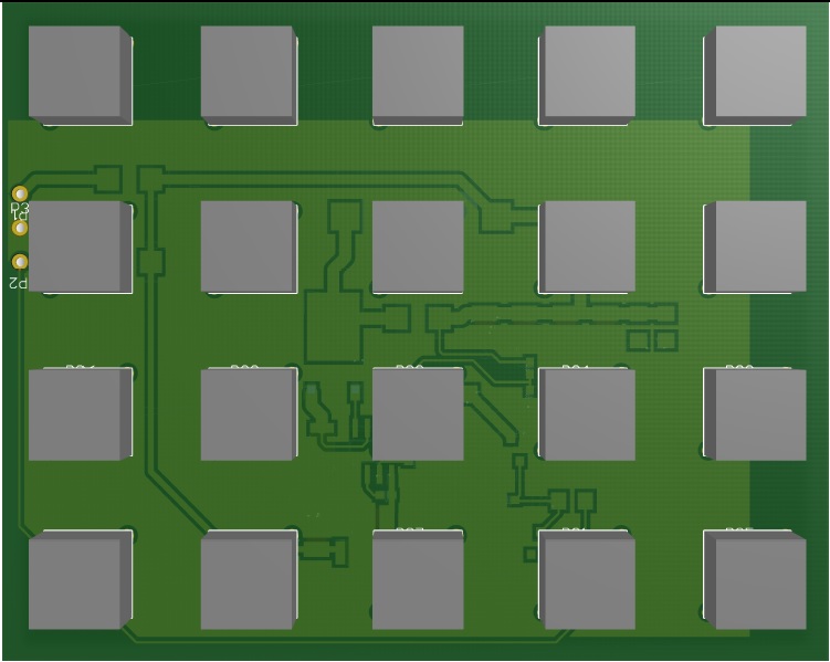
Posted by: zymurgist Nov 28 2013, 07:43 AM
Great to hear of your progress.
Posted by: Cairo94507 Nov 28 2013, 08:05 AM
Excellent work. Nice to see this project coming together.
I see you are going to use orange LED's for the turn signals, if by chance I wanted to stay with the US taillight configuration could they all be red? Is there a way to make the turn signal dual colors (switchable) if one wanted to go from euro to US and back? I know….but I thought I would ask.
Happy Thanksgiving.
Posted by: Scarlet75 Nov 28 2013, 08:49 AM
check this out. >>>>>>.
http://www.superbrightleds.com/cat/led-vehicle-replacement-bulbs/vehicle/1974-porsche---/49---/
they even have the relay for the led lights. I'm thinking...
Those are what I have in mine right now. I also have a FLAPS third brake light mounted so that you wont notice it until its on. Although I dont have all my resistors in place yet, the turn signals still flash I just don't get the flashing green light on my dash. Just my $.02
Posted by: Spoke Nov 30 2013, 03:21 PM
Excellent work. Nice to see this project coming together.
I see you are going to use orange LED's for the turn signals, if by chance I wanted to stay with the US taillight configuration could they all be red? Is there a way to make the turn signal dual colors (switchable) if one wanted to go from euro to US and back? I know….but I thought I would ask.
Happy Thanksgiving.
The high power LEDs I am using are from Cree and come in white, amber, red, red-orange, and blue. Red LEDs can be substituted for amber.
Switchable usually have 2 or more LEDs mounted in a single package with either 2 or 3 connections. Not planning to do any switching at this point.
I made about 100 changes to the PCB over the weekend. The plan now is to order the boards for the brake/taillights next week. All the parts are available on Digikey but I'm going to go through my contact at Arrow for better pricing.
Still trying to figure out how to connect to the existing brake light socket. I want something like a bulb base with wires going to the PCB to plug into the existing taillight fixture. If I have to I will cannibalize a couple of bulbs and add wires to them to connect the PCB.
I want to make as little modifications to the taillight fixture as possible and be able to return to the bulb if I need to work on the PCB. (Don't want to take the 914 out of service because of the PCB).
Attached image(s)
Posted by: timothy_nd28 Nov 30 2013, 03:38 PM
Looks awesome! Digikey charges sales tax and I found them to be a tad more expensive. Check out mouser.
Posted by: mikesmith Nov 30 2013, 03:41 PM
You may be better off using yellow for amber. Certainly, I've tried red LEDs in amber tinted housings and been less than happy with the results. The yellow LEDs are pretty shockingly yellow, but they are very attention-getting...
Posted by: McMark Nov 30 2013, 07:06 PM
If you want a spare set of taillight housings, just ask.
Posted by: Spoke Dec 1 2013, 01:29 AM
If you want a spare set of taillight housings, just ask.
Thanks Mark, I think I'm good now. I will use my 914 as the test bed for these units.
Mounting holes were added for #6 screws and the corners trimmed to fit deeper in the housing.
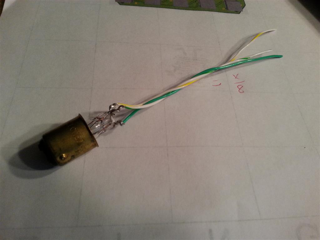
Still trying to figure out how to power this unit with minimally invasive techniques. This is just the guts of an 1157 bulb with wires soldered to the filament leads. Solder the wires to the board and plug the base into the socket for power.
Posted by: mikesmith Dec 1 2013, 01:35 AM
You can get bayonet to wire adapters from the usual suspects, but honestly the bayonets are one of the weakest points in the original design. The wires from the back housing have spade connectors on them - better to solder lugs to the back of the PCB, or use flying leads if you are retaining the reflectors and just snake out through the fittings.
In my case, at least, the unsupported wires are fraying off the riveted crimps, so an option to refurb and solder direct to the brass crimps might also be worthwhile.
Posted by: Harpo Dec 1 2013, 06:24 AM
Glad to see more progress on this project. Keep up the good work.
Thanks
David
Posted by: Spoke Dec 1 2013, 09:38 AM
You can get bayonet to wire adapters from the usual suspects, but honestly the bayonets are one of the weakest points in the original design. The wires from the back housing have spade connectors on them - better to solder lugs to the back of the PCB, or use flying leads if you are retaining the reflectors and just snake out through the fittings.
In my case, at least, the unsupported wires are fraying off the riveted crimps, so an option to refurb and solder direct to the brass crimps might also be worthwhile.
Could you point to one of the usual suspects who carries bayonet wire adapters? I haven't had any luck searching for them.
Agreed the bayonets are a weak point. At this point, I'm trying to be minimally invasive to the light housing. This would also make it easy for others to connect theirs. A PCB connector and direct wiring could be in the future.
Posted by: Spoke Dec 1 2013, 09:54 AM
OK, I'm getting closer to what I need with this empty base.
http://www.superbrightleds.com/moreinfo/empty-bases-sockets/bay15d-empty-ba15-base/706/773/
Post Whore
Posted by: Spoke Dec 1 2013, 09:54 AM
OK, I'm getting closer to what I need with this empty base.
http://www.superbrightleds.com/moreinfo/empty-bases-sockets/bay15d-empty-ba15-base/706/773/
[attachmentid=424769]
Post Whore
Attached image(s)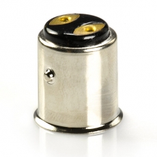
Posted by: Spoke Dec 1 2013, 09:54 AM
OK, I'm getting closer to what I need with this empty base.
http://www.superbrightleds.com/moreinfo/empty-bases-sockets/bay15d-empty-ba15-base/706/773/
Posted by: Spoke Dec 1 2013, 10:05 AM
Found this one. A bit expensive at 8.95 Euro.
Attached image(s)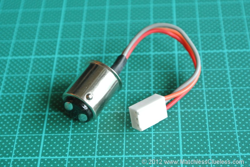
Posted by: Spoke Dec 1 2013, 10:15 AM
Vintage Auto Accessories has this one.
http://www.closertowholesale.com/p-116-2-1157-wire-plug-adapters-for-tail-lamp-sockets-covert-wiring-to-1157-socket.aspx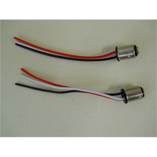
Posted by: McMark Dec 1 2013, 02:26 PM
So is this board going to sit inside the 'chrome' reflector? That piece comes out with just two screws. Why not pull the whole thing and make a board that uses those two screws to mount? Plus behind the chrome piece are lengths of wire you can tap directly into. Add spade connectors and you've got an interchangeable piece if you need to swap back...
Posted by: gothspeed Dec 1 2013, 02:42 PM
So is this board going to sit inside the 'chrome' reflector? That piece comes out with just two screws. Why not pull the whole thing and make a board that uses those two screws to mount? Plus behind the chrome piece are lengths of wire you can tap directly into. Add spade connectors and you've got an interchangeable piece if you need to swap back...
+1 .......
Posted by: mikesmith Dec 1 2013, 03:57 PM
So is this board going to sit inside the 'chrome' reflector? That piece comes out with just two screws. Why not pull the whole thing and make a board that uses those two screws to mount? Plus behind the chrome piece are lengths of wire you can tap directly into. Add spade connectors and you've got an interchangeable piece if you need to swap back...
What I said above.
The big reason to keep the chromed plastic is that it includes the separator pieces that prevent bleed between the different coloured regions, and it gives you a frame that you can attach, single-coloured LED assemblies to.
Assuming Spoke is using the (cheap, popular, efficient) 5050SMD LEDs, they tend to have a beam angle around 120°, so you can't position them very far from the diffuser before you need to deal with bleed.
If you wanted to do without the separators you would have to move the LEDs much closer to the diffuser, but then you're going to have to fabricate a replacement carrier and work out how to attach it, or build a much bigger PCB and sort out how to avoid cross-bleed.
If someone had a good idea for building a sheet aluminium carrier that sat ~15mm back from the diffuser (needs to be mostly flat, so only bends between colour segments) and supporting it from the stock fasteners, that would make this sort of thing much easier. This would also give you somewhere to attach some of the red reflective tape to make the clear rears more DOT-friendly.
Posted by: McMark Dec 1 2013, 06:43 PM
No I get it. But building separators seems like a trivial task to me, especially for testing. But I realize there's more than one way to skin a cat.
Posted by: Spoke Dec 1 2013, 08:14 PM
So is this board going to sit inside the 'chrome' reflector? That piece comes out with just two screws. Why not pull the whole thing and make a board that uses those two screws to mount? Plus behind the chrome piece are lengths of wire you can tap directly into. Add spade connectors and you've got an interchangeable piece if you need to swap back...
This test board will fit in between the reflector. My motivation with this small board is to get my feet on the ground regarding LED power, the LED driver and the LED lenses. Once that is figured out, then I will have more confidence to design the board shown in post #17.
It is likely that there will be more than one board design. Right now it would be the small board and the larger full taillight board requiring the removal of the chrome reflector.
Dividers would not be an issue and could be done with metal or even PCB material.
Posted by: Spoke Dec 4 2013, 02:58 PM
Ordered a couple of boards today.
I made a couple of more changes to the circuitry and added some side view LEDs.
These LEDs would be used at the tip of the boards to illuminate the side marker. The side mounted LEDs have significantly less current rating (30ma) so it will be interesting to see how well they show up.
Here's a view from the side.
Altium is pretty cool as in 3d mode it allows you to go inside the board and look at the different layers, vias, and holes. You can see the holes and vias in this shot.
Attached image(s)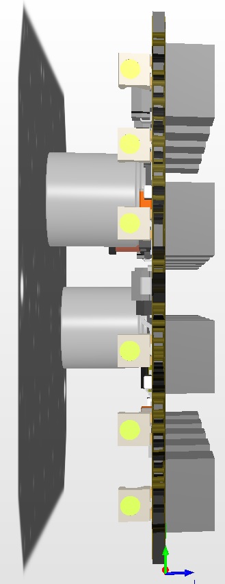
Posted by: JmuRiz Dec 4 2013, 03:08 PM
Check out these units, a lot of local 356 guys have them:
http://www.culayer.com/Porsche_356.htm
I'm planning on buying a set when I save up the $$, it's nice to have bright lights, especially on tiny lenses like the 356 has.
Posted by: mikesmith Dec 4 2013, 04:22 PM
The Classic Auto LEDs folks (http://www.classicautoleds.com) do something similar for a number of different vehicles, too.
Their approach is fairly low-tech (TH LEDs, multiple PCBs) but their BoM cost is likely to be very good.
Still not as much fun as designing your own. 8)
Posted by: timothy_nd28 Dec 4 2013, 04:25 PM
How many vias are on the board?
Posted by: Spoke Dec 4 2013, 06:09 PM
Check out these units, a lot of local 356 guys have them:
http://www.culayer.com/Porsche_356.htm
I'm planning on buying a set when I save up the $$, it's nice to have bright lights, especially on tiny lenses like the 356 has.
The Classic Auto LEDs folks (http://www.classicautoleds.com) do something similar for a number of different vehicles, too.
Their approach is fairly low-tech (TH LEDs, multiple PCBs) but their BoM cost is likely to be very good.
Still not as much fun as designing your own. 8)
These both use the through hole 5mm LEDs which are generally inexpensive. Hard to tell how they are driving them. maybe a linear regulator followed by some resistors?
How many vias are on the board?
There are 61 vias on the board. Most of them connect the ground planes on the top and bottom of the board. I've covered the top and bottom with ground for thermal considerations.
Posted by: mikesmith Dec 4 2013, 06:49 PM
The Classic Auto LEDs folks (http://www.classicautoleds.com) do something similar for a number of different vehicles, too.
Their approach is fairly low-tech (TH LEDs, multiple PCBs) but their BoM cost is likely to be very good.
Still not as much fun as designing your own. 8)
These both use the through hole 5mm LEDs which are generally inexpensive. Hard to tell how they are driving them. maybe a linear regulator followed by some resistors?
I just remembered that I had a set in a box here from another stalled project, so I pulled one out to see. It looks like a simple constant current setup using a ZTX749, feeding a bunch of LED + resistor strings in parallel.
For the one I measured (a turn signal) I can't say that makes me very happy. At 13.8V in and 250mA LED current, the (un-heatsinked) transistor is dropping 2.75V and it's too hot to touch after just a couple of seconds.
I guess it's a good thing I'm just going to box these up and sell them off. The build quality is fine, and they're definitely bright enough, but the thermal setup on the current source is a big no.
Posted by: Spoke Dec 6 2013, 08:50 AM
I just remembered that I had a set in a box here from another stalled project, so I pulled one out to see. It looks like a simple constant current setup using a ZTX749, feeding a bunch of LED + resistor strings in parallel.
For the one I measured (a turn signal) I can't say that makes me very happy. At 13.8V in and 250mA LED current, the (un-heatsinked) transistor is dropping 2.75V and it's too hot to touch after just a couple of seconds.
I guess it's a good thing I'm just going to box these up and sell them off. The build quality is fine, and they're definitely bright enough, but the thermal setup on the current source is a big no.
After viewing those aftermarket 356 LED lights using common 5mm round LEDs, I decided to try one just to see how it performs.
It seems they put 4 LEDs in series which would drop about 10V leaving 2.75V across the transistor.
I have 21 strings of 3 LEDs in series at 40mA each string. I thought about 4 in a string but at 10V the LEDs would barely light. So the current draw on this board will be about 800ma.
I kept it simple using resistors in each string to drop voltage and allow a low operating voltage and disperse the heat sources (resistors) across the board.
The LEDs are manufactured by Vishay and are dirt cheap at 15 cents each.
Attached image(s)
Posted by: mikesmith Dec 6 2013, 10:24 AM
You could also consider using an LED backlight driver like the NCS29001, and a 555 to provide the PWM dimming signal for tail vs. brake functions. That would let you run all the LEDs in a single string with very low dissipation.
(It's a new part, but you might be able to get samples from OnSemi...)
Posted by: Spoke Dec 6 2013, 03:48 PM
You could also consider using an LED backlight driver like the NCS29001, and a 555 to provide the PWM dimming signal for tail vs. brake functions. That would let you run all the LEDs in a single string with very low dissipation.
(It's a new part, but you might be able to get samples from OnSemi...)
I looked at that boost switcher along with many others. Couldn't find one that suited my needs that was simple, cheap, and rugged. The NCS29001 doesn't have enough voltage capability (18V) for automotive use. I was looking for boost switchers with >36V capability to take into consideration transients on the power supply leads (brake, turnsignal, and taillight).
On the other board I'm using the IS31LT3948. It's cheap and simple to use. I'm curious to see how it starts up as with turnsignals especially, it will be turning on and off on a regular basis.
The datasheet suggested a 220uF cap on the input which would be charged every time the brake, turnsignal, or taillight turns on. Seems like a lot of capacitance so I will try a 22uF cap to begin with just to lower the inrush current on turn on.
Posted by: Cairo94507 Dec 6 2013, 05:25 PM
Yeah….what he just said
Seriously, I am really looking forward to LED taillights. They are going to be so nice and increase safety by a ton. Thanks for tacking this major project.
Posted by: mikesmith Dec 6 2013, 05:28 PM
You could also consider using an LED backlight driver like the NCS29001, and a 555 to provide the PWM dimming signal for tail vs. brake functions. That would let you run all the LEDs in a single string with very low dissipation.
(It's a new part, but you might be able to get samples from OnSemi...)
I looked at that boost switcher along with many others. Couldn't find one that suited my needs that was simple, cheap, and rugged. The NCS29001 doesn't have enough voltage capability (18V) for automotive use. I was looking for boost switchers with >36V capability to take into consideration transients on the power supply leads (brake, turnsignal, and taillight).
On the other board I'm using the IS31LT3948. It's cheap and simple to use. I'm curious to see how it starts up as with turnsignals especially, it will be turning on and off on a regular basis.
The datasheet suggested a 220uF cap on the input which would be charged every time the brake, turnsignal, or taillight turns on. Seems like a lot of capacitance so I will try a 22uF cap to begin with just to lower the inrush current on turn on.
18V in conjunction with a polyswitch and a zener would probably be fine. If you are seeing 18V input on a taillight then something is pretty wrong...
That ISSI part looks pretty neat, and the pricing is definitely in the right ballpark.
= Mike
Posted by: Spoke Dec 16 2013, 03:49 PM
Received the high power LED boards today. They look good and fit in the brake housing nicely. These boards are just to see if the circuit works as a brake and as well as a blinker.
Parts are on order and hopefully will see the parts before Christmas.
Attached image(s)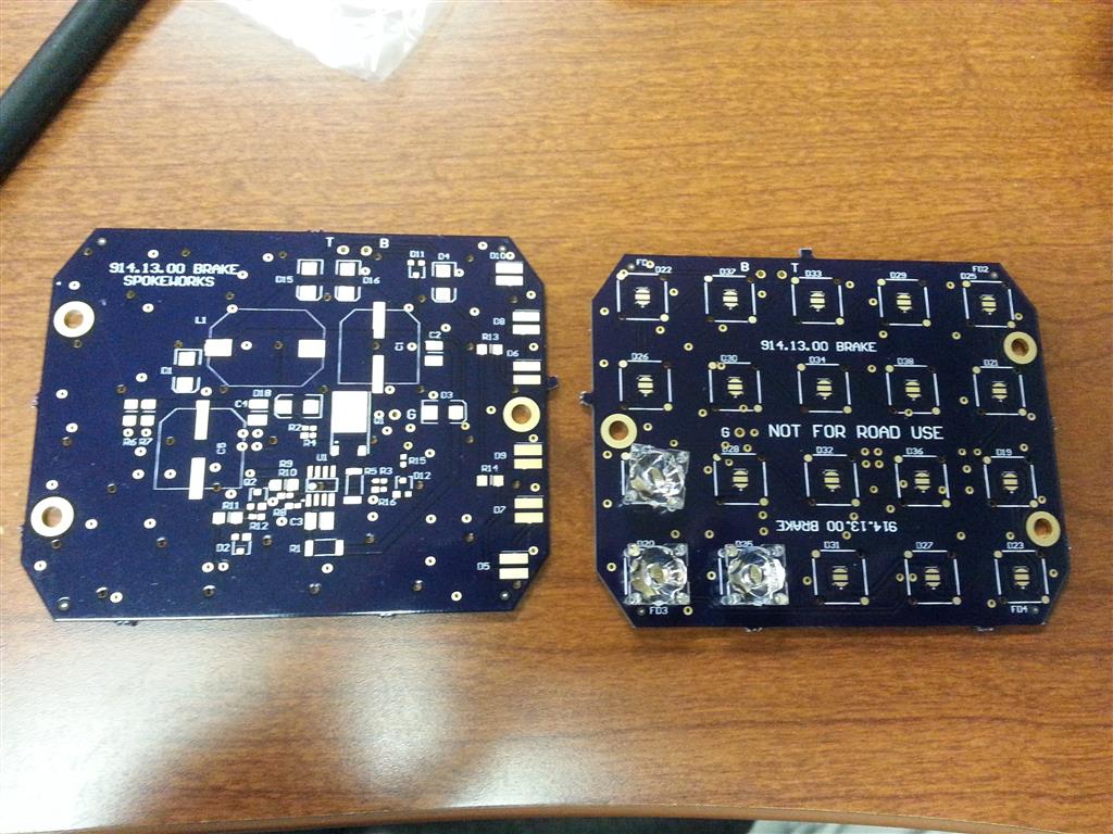
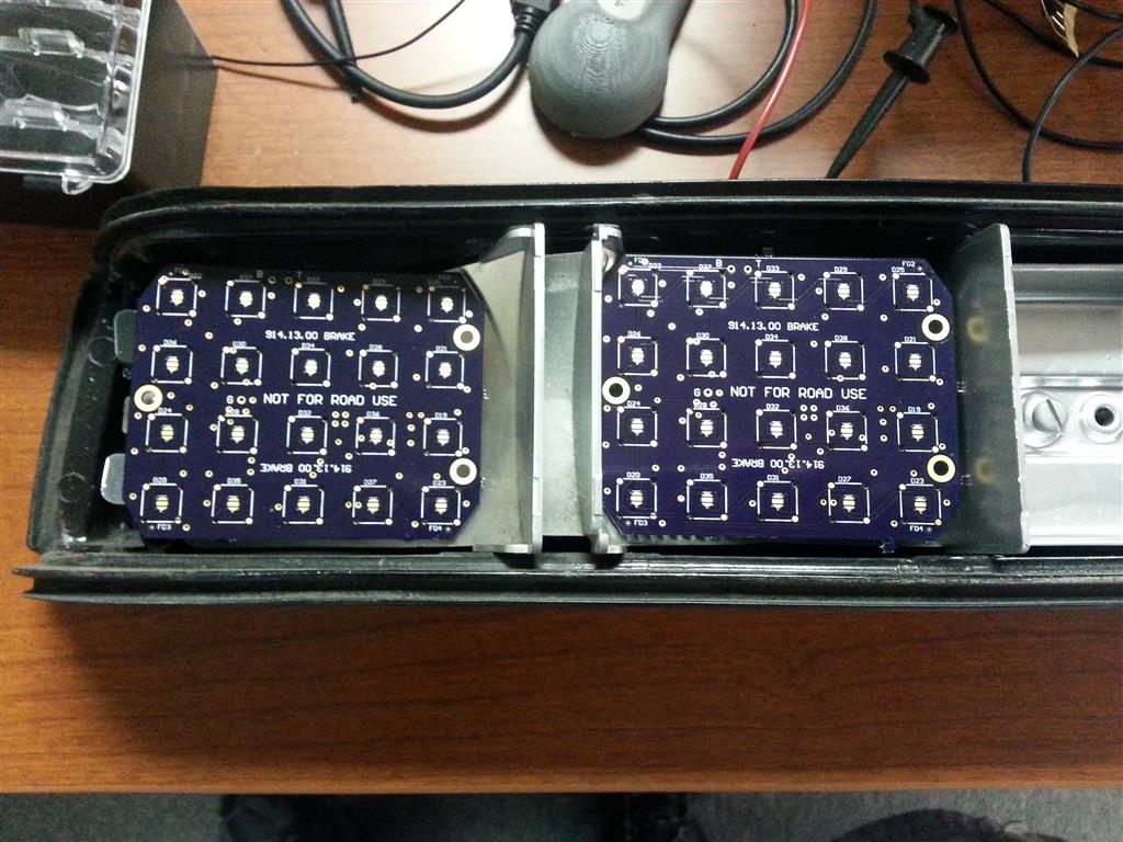
Posted by: Spoke Dec 16 2013, 03:51 PM
The lenses fit nicely in the holes provided. Opposite feet have a dimple to help align them over the LED. The lenses make all the difference in the world when trying to focus the LED light towards the rear of the car.
Attached image(s)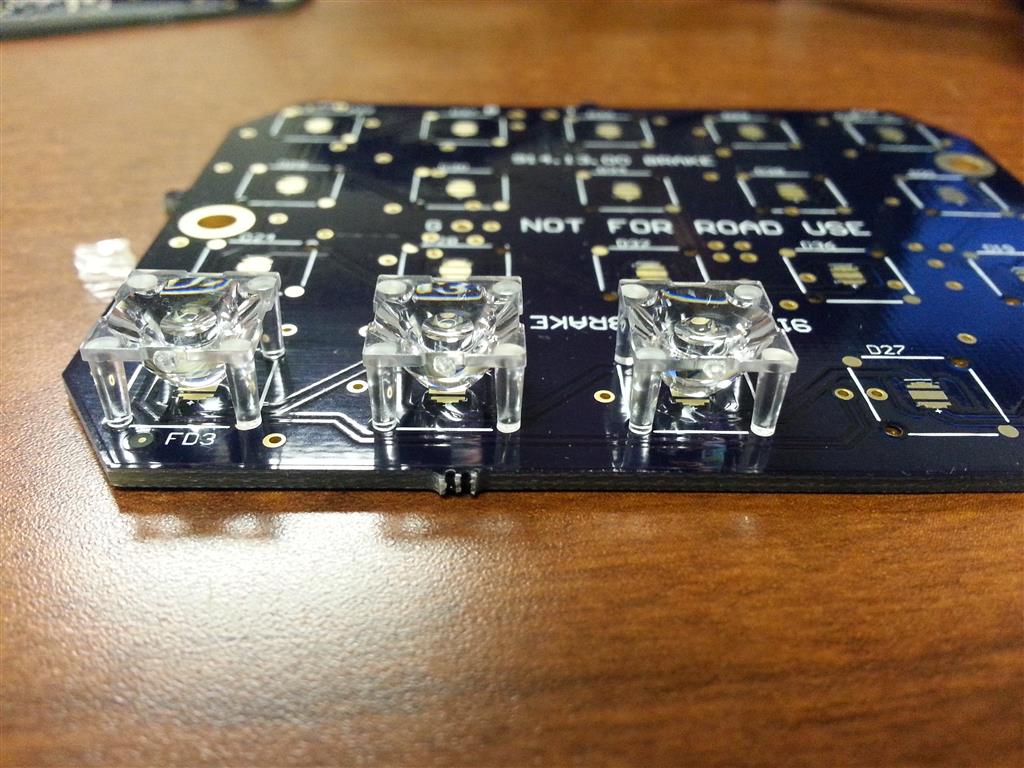
Posted by: Spoke Dec 16 2013, 03:52 PM
Also got some bulb bases so I can quickly switch in/out the LED board and existing lamps.
Attached image(s)
Posted by: CptTripps Dec 16 2013, 03:53 PM
Holy shit! Those look bad-ass!
Posted by: Chris H. Dec 16 2013, 04:02 PM
You're REALLY DOING THIS!!!!
Posted by: zymurgist Dec 16 2013, 04:14 PM

Posted by: Harpo Dec 16 2013, 06:21 PM
Very impressive, keep up the good work
Harpo
Posted by: Cairo94507 Dec 16 2013, 07:13 PM
I love the direction these have gone. Great work and high quality. I really like these.  Can't wait to see them all lit up with a taillight lens in place.
Posted by: effutuo101 Dec 17 2013, 09:08 AM
Great. Another thing to spend money on for my car.
Nice work! 
Posted by: monkeyboy Dec 17 2013, 11:04 AM
Can't wait to see these work! Awesome!
Posted by: Spoke Dec 18 2013, 03:10 PM
Received the alternate boards today. This one uses lower power through hole 5mm LEDs. This board will be easy to build since the through hole devices are easy to solder.
Attached image(s)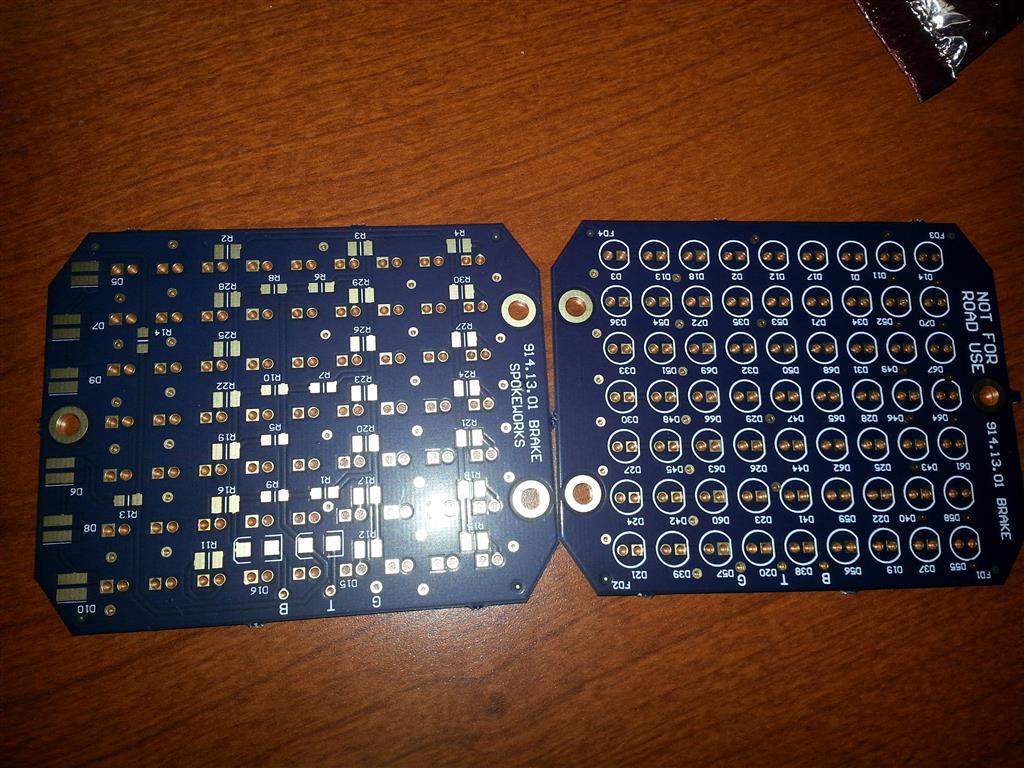
Posted by: mikesmith Dec 18 2013, 04:53 PM
(please let me know if you'd rather I didn't clutter your thread with stuff like this)
I figured it'd be interesting to mock something up using 'smart' LEDs; this is 88 WS2812s behind a 'euro' lens. Currently just running some static patterns, but fully logic controlled so they could literally do anything.
My phone does a bad job dealing with how bright they are, so it gets hard to distinguish red from amber, but in person it's quite clear. You'd have the most flexibility with the clear 'italian' lenses, since then you're not limited to the colours you can display in each region. IMG_0102.MOV ( 2.36mb )
Number of downloads: 97
IMG_0102.MOV ( 2.36mb )
Number of downloads: 97
(hmm, not sure how to inline a video that's hosted here...)
Posted by: Spoke Dec 18 2013, 06:17 PM
Those WS2811s look pretty cool. I looked for them online but couldn't find them at findchips.com so see how expensive they are.
I tested the side LEDs to see how they would work for the side light. I used 6 LEDs. The result wasn't much different than the single small bulb.
Single Small Bulb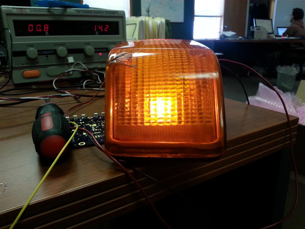
6 SideLEDs. The LEDs give a more spread out light. Not bad but not better. More efficient LEDs would work better. These LEDs max out at 20mA. There are 50mA 5mm LEDs which would work better.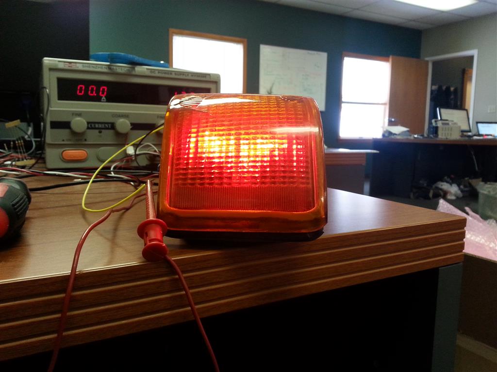
Posted by: Spoke Dec 18 2013, 06:21 PM
I built up one of the 5mm LED lights. Pretty easy to build with the through-hole LEDs and large resistors. The sideLEDs were not populated on this board.
Attached image(s)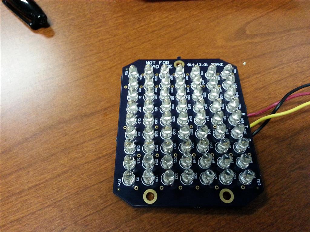
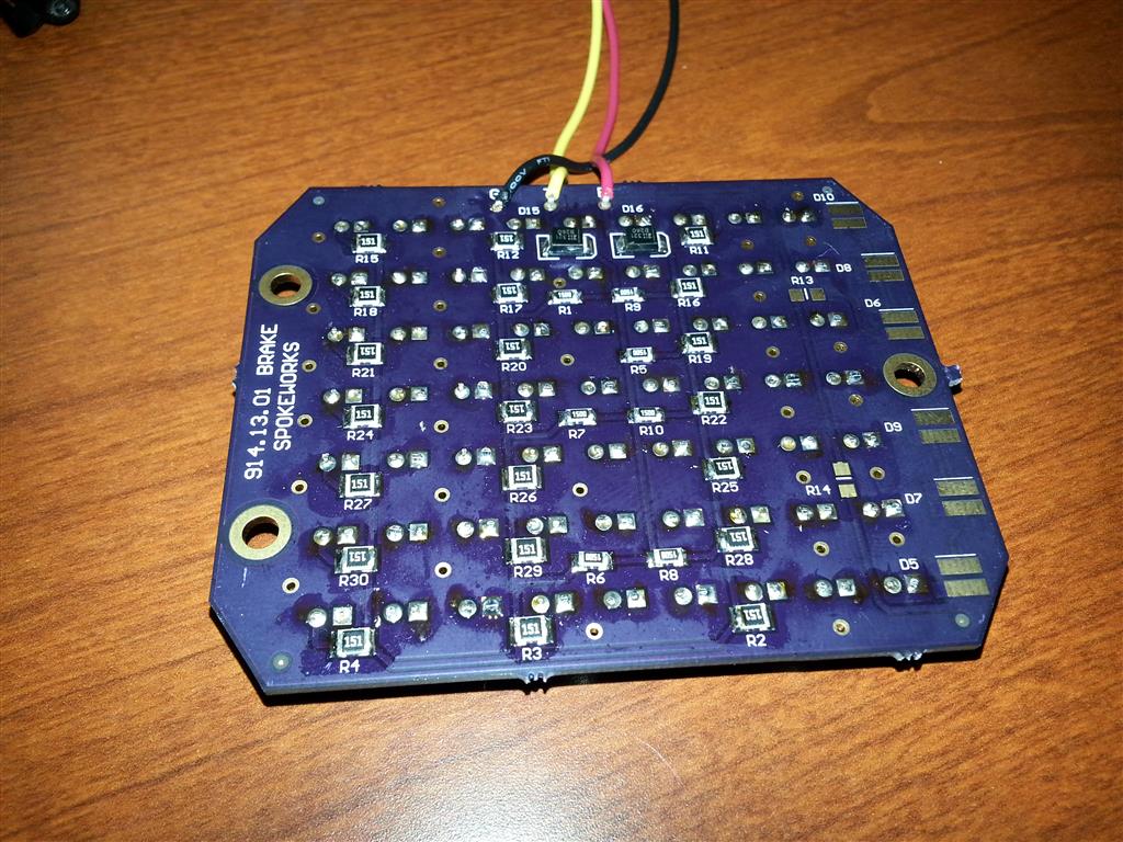
Posted by: Spoke Dec 18 2013, 06:30 PM
The 5mm LEDs are a good bit brighter than the brake lamp. The light from the LEDs is more focused than the lamp.
I tried to get some comparison pics of both lights.
Here's a view looking straight at the light from about 12 feet away.
Lamp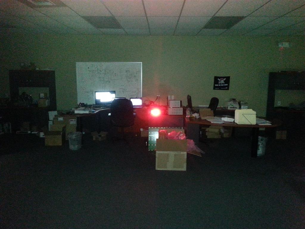
LEDs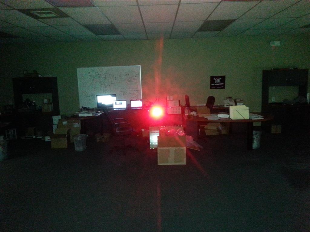
Posted by: Spoke Dec 18 2013, 06:33 PM
This shot is with the brake light pointing up towards the ceiling.
Again the lamp light is more dispersed than the LED. The LED is quite a bit more concentrated.
Brake Lamp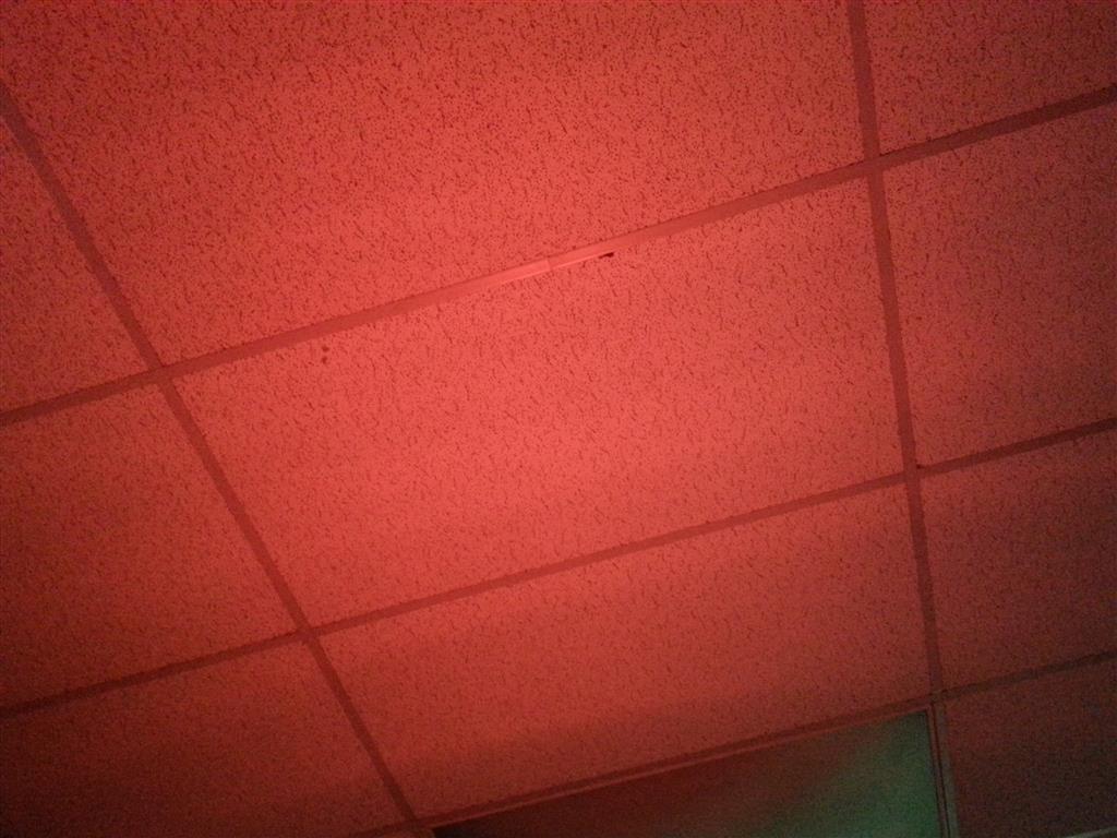
LEDs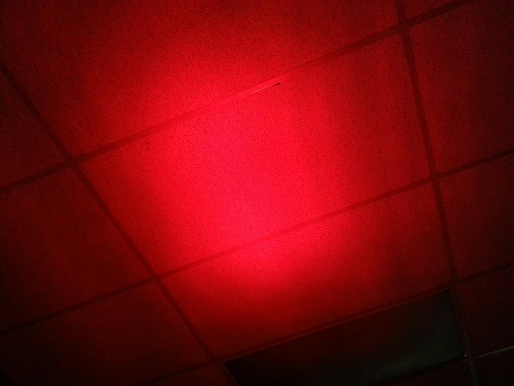
Posted by: Spoke Dec 18 2013, 06:37 PM
This shot is most telling of the difference in output.
The wall is about 12 feet away and I am about 6 feet away from the lights.
My outline is somewhat noticeable with the lamp but nothing like the light produced by the LEDs.
Lamp: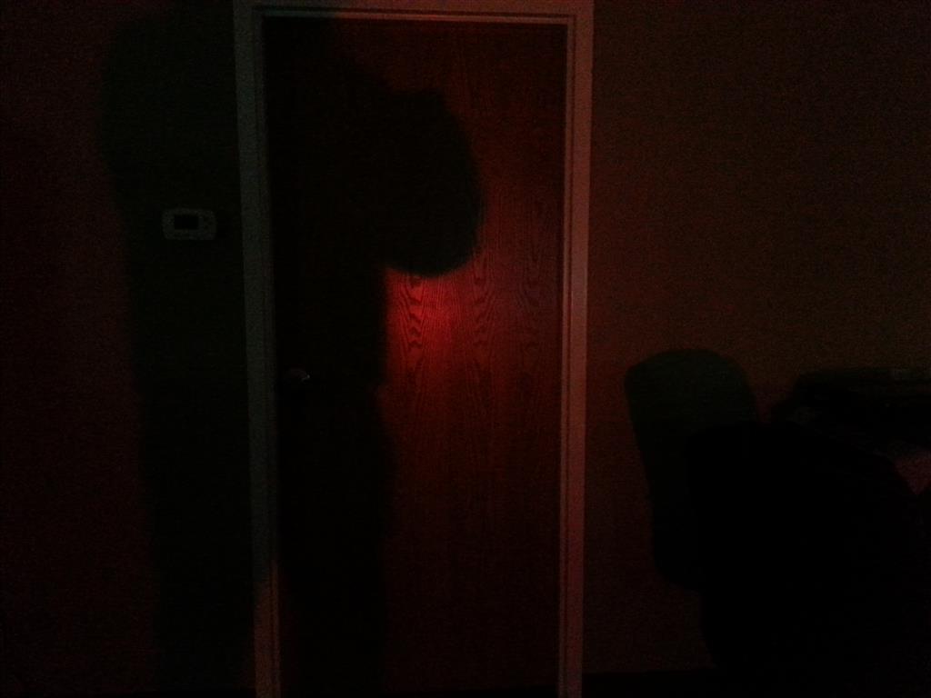
LEDs:
Posted by: Cairo94507 Dec 18 2013, 07:22 PM
This is so sweet! I love watching these come together. Can't wait to see a completed set installed. You could leave a stock taillight on one side and the LED taillight on the other for easy comparison. This project is making terrific progress. This truly will be a 914 saver.
Posted by: mikesmith Dec 18 2013, 07:22 PM
That shadow contrast trick is pretty neat.
Re: the WS2812 LEDs, they tend to run about $0.20 each in quantity. I bought these on a strip backing and mounted them to some Depron loosely secured to the back of the lens (I did say it was a mockup 8).
Posted by: CptTripps Dec 18 2013, 07:42 PM
Can't wait for a set. Great work!
Posted by: Spoke Dec 20 2013, 10:34 PM
I mounted the one 5mm LED brake light tonight.
I made 3 small brackets and attached to the inside of the brake fixture.
Before attaching the brackets to the fixture, I had to determine the plane on which to place the PCB so that it would be perpendicular to the vehicle. The LED light is concentrated 90 degrees from the mounting surface of the PCB. We want the majority of the light to be focused directly behind the vehicle.
I applied the piece of tape while the fixture was mounted on the car. Since the rear of the car is slightly rounded, the tape and plane of the PCB is not parallel to the surface of the fixture.
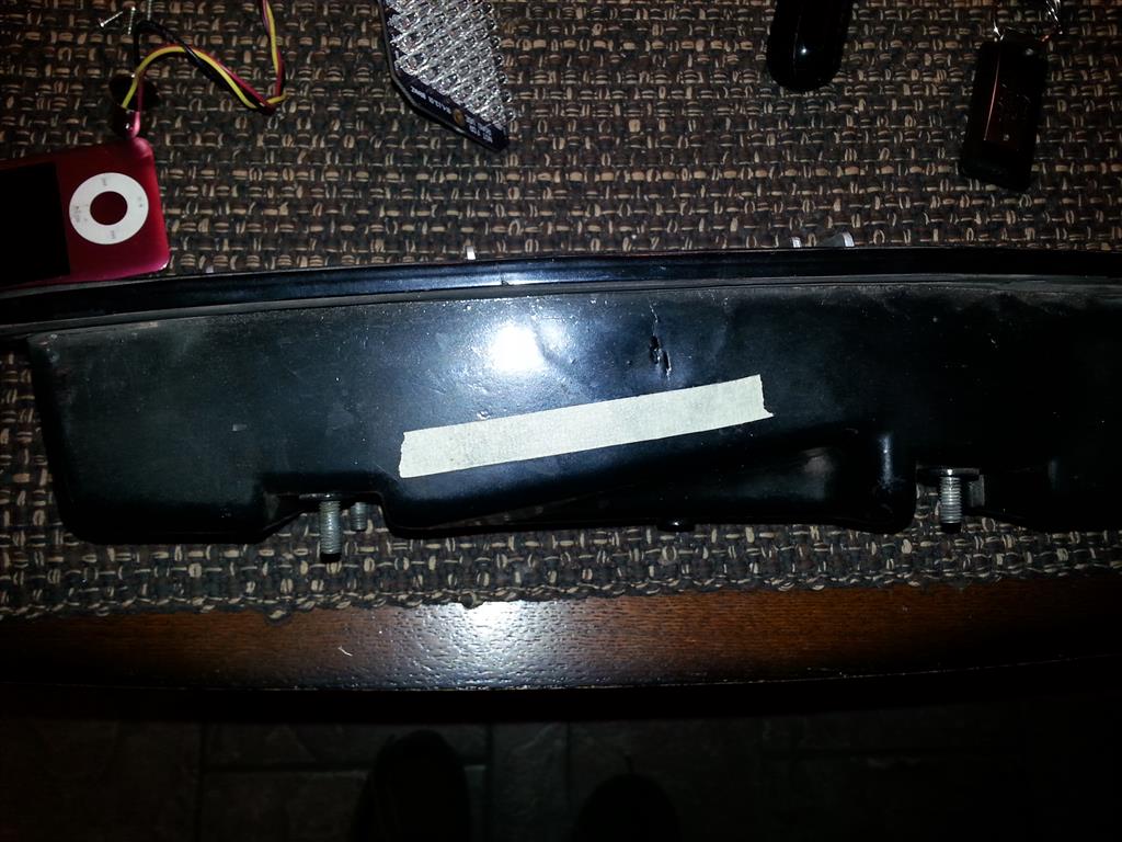
After determining the angle of the PCB, I drilled pilot holes and secured the brackets with 3/8 inch #6 screws.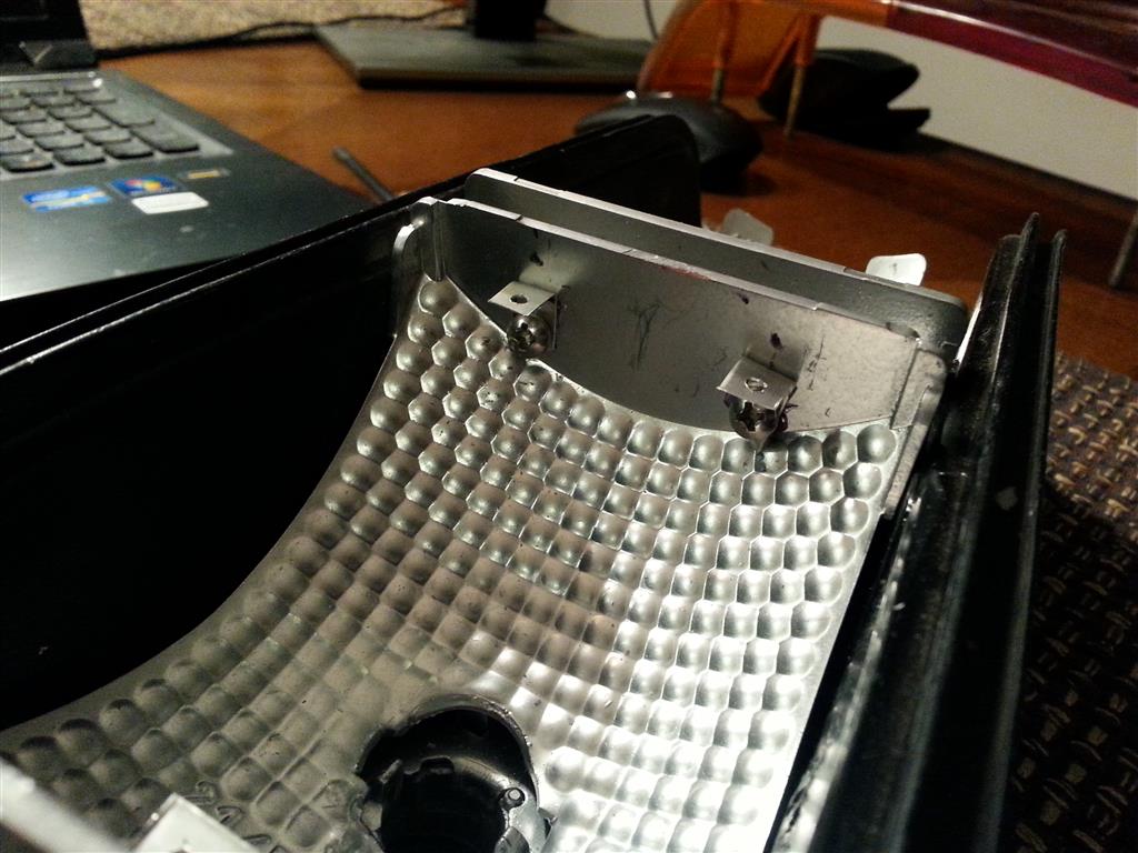
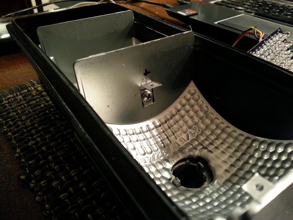
Posted by: Spoke Dec 20 2013, 10:41 PM
A 1057 base was soldered onto the pigtail from the PCB. This will make removing the PCB quite easy. This board is a test platform and I don't expect it to remain in the vehicle forever.
I still have the other high power LED design to build and test.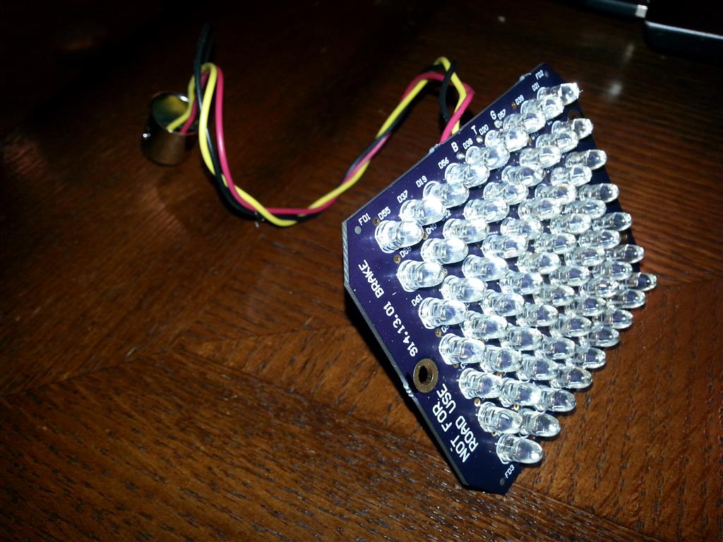
The board mounted in the light fixture. The board fits quite nicely. It probably could have been a few millimeters taller but will do the job quite nicely.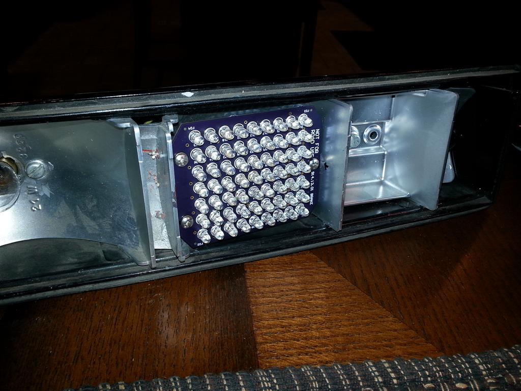
Posted by: Rleog Dec 21 2013, 04:44 AM
Great to see this coming together. Very nicely done.
Posted by: Spoke Dec 21 2013, 08:29 AM
Here's some comparisons of the brightness of the brake light. As before in the office, there is no comparison to the light output directed behind the vehicle.
The 1057 lamp is bright and shines some light rearwards but the LEDs illuminate rearward big time.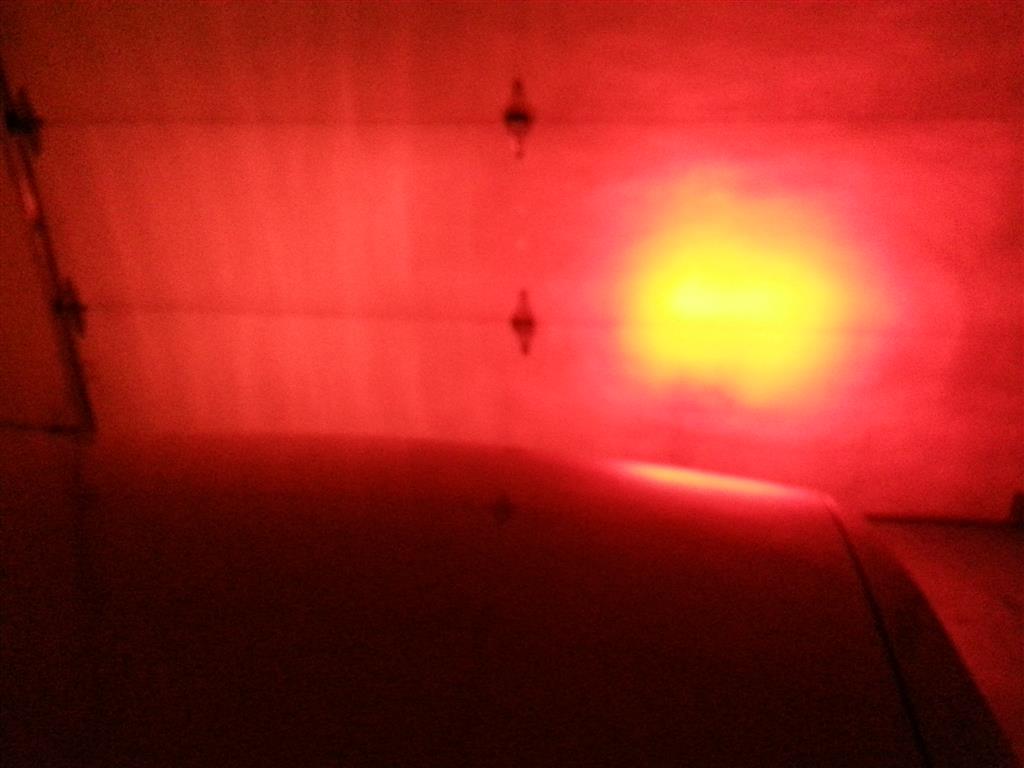
Also a video of the brake comparison:
https://www.youtube.com/watch?v=jQx6pgGpsoI
Here's the running light comparison. Not sure if they are too bright for running lights. They are definitely pulling more current than I designed them for. I may tune these down a bit.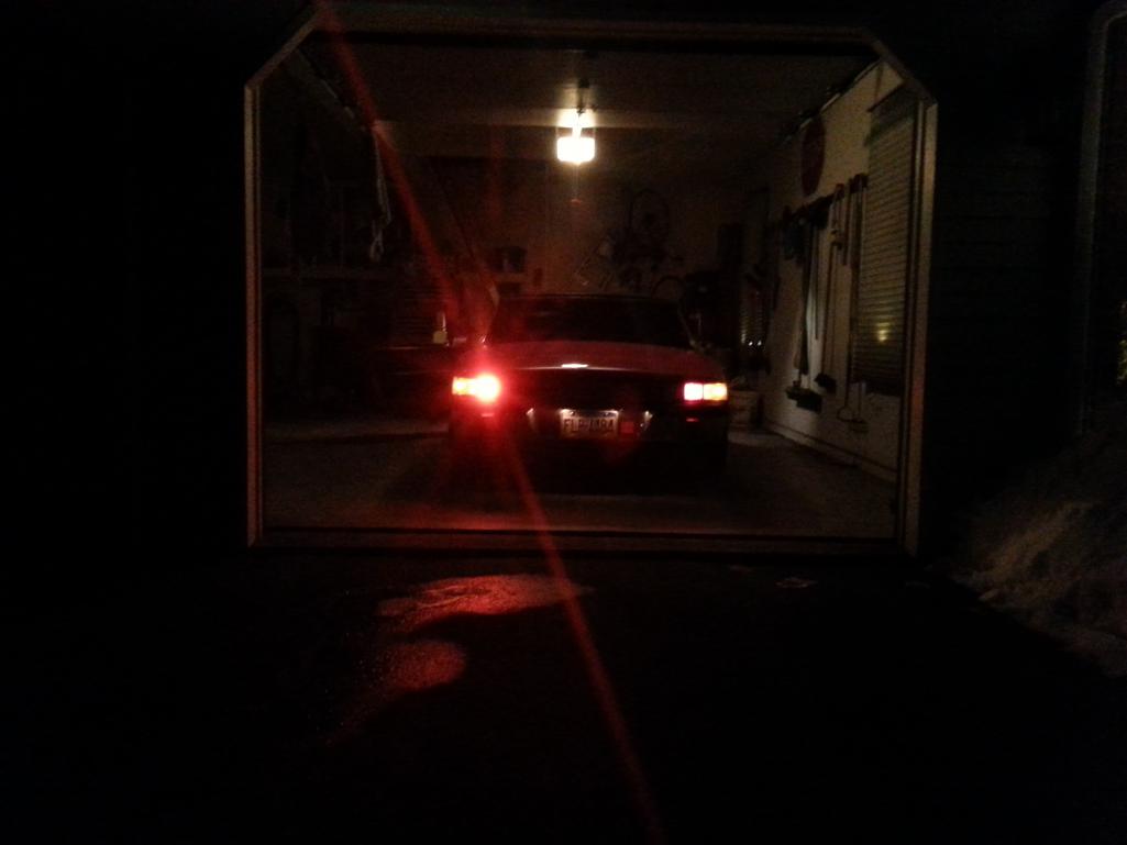
Posted by: Speedmster Dec 21 2013, 11:19 AM
Thats a pretty big difference. Looks good!
Posted by: StratPlayer Dec 21 2013, 11:59 AM
Bit to bright
Posted by: Rleog Dec 21 2013, 12:41 PM
Well....Duh!
I looked at the 1st pic above, then wondered where was the pic showing the regular 1057 bulb. 
Then I realized, after looking at the lower pic, that the 1057 lamp was also lit. What a contrast. I think you have a winner here.
Posted by: stugray Dec 21 2013, 01:22 PM
Sorry, I didnt read the whole thread but curious:
Have you tried single CREE XRE type of LEDs shining backwards towards the reflector?
I build LED lighting for reef fishtanks (THOUSANDS of watts) and some for local grow operations (I live in Colorado ...wink, wink....).
I have built some pure red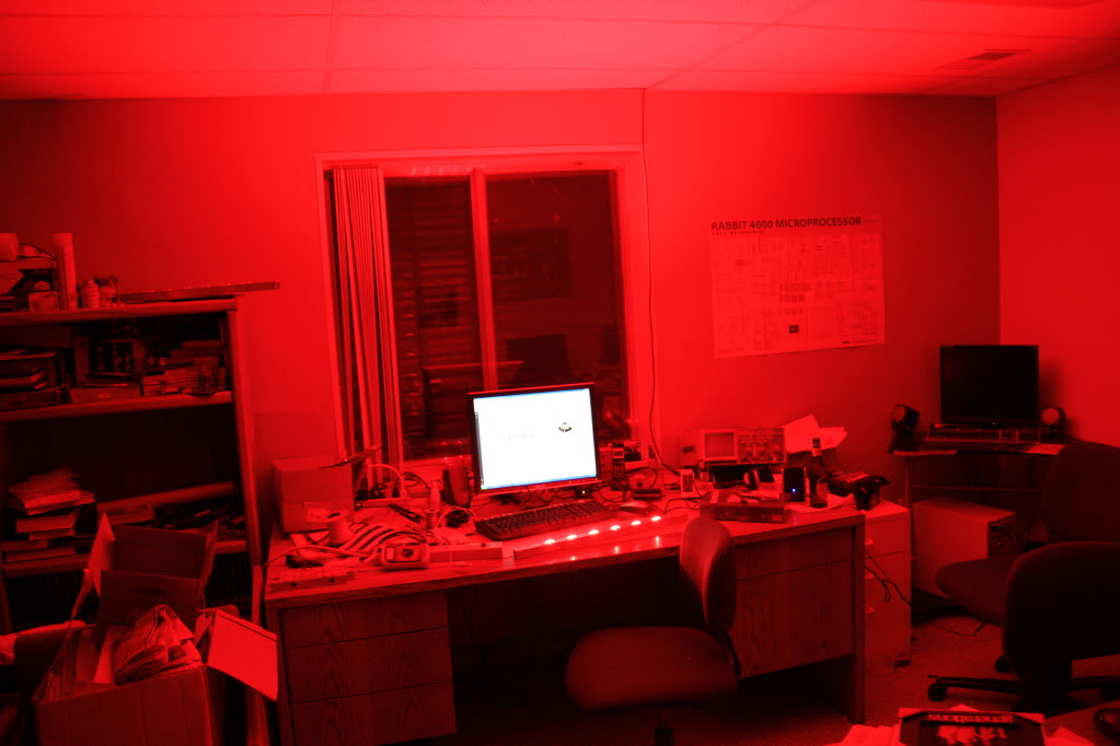
Or trying to match the Sun's spectrum in strips: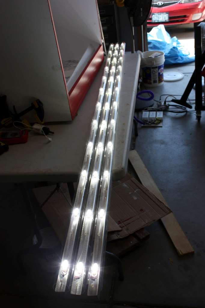
Or "spotlight" types: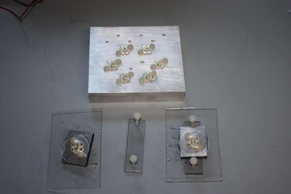
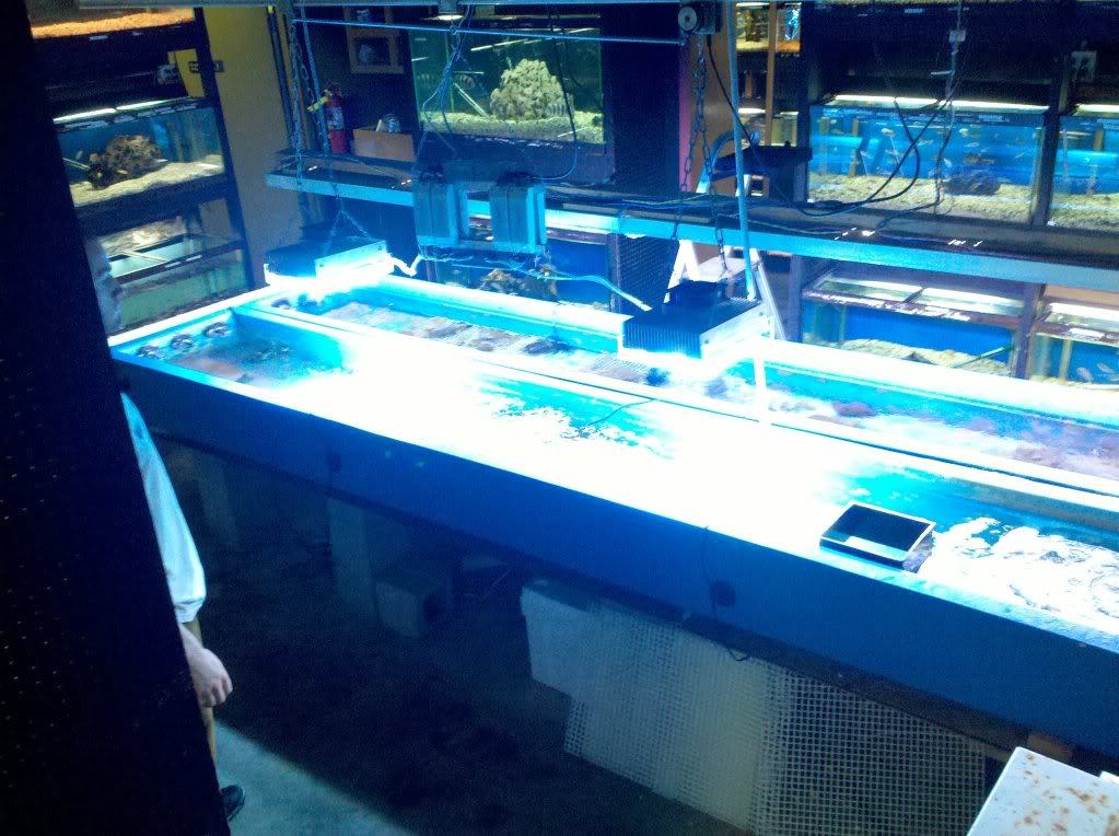
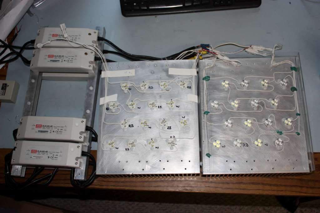
The drivers I use are meanwell AC-DC constant current, but you could easily use the Buckpuck DC-DC versions.
Posted by: CptTripps Dec 21 2013, 06:35 PM
I think that's a little too bright for running lights. For brake lights, they could be as bright as the sun! Little cars + weak brake lights = disaster.
Keep at it. Those are awesome.
Posted by: palmer_md Dec 21 2013, 10:52 PM
I think that's a little too bright for running lights. For brake lights, they could be as bright as the sun! Little cars + weak brake lights = disaster.
Keep at it. Those are awesome.
I agree this project is awesome. Keep at it. The key in my view is the difference between the driving light and the brake light. I've seen a few cars with led lights that the driving light is so bright that the brakes are not as noticeable. Need to have a toned down driving light and a bright brake light.
Posted by: stugray Dec 22 2013, 10:33 AM
They make adjustable "buckpuck" drivers so you could just turn them down to where you want them.
Posted by: Spoke Dec 22 2013, 07:05 PM
The Buckpuck was one of my design wins at my last job. The MP2483 is the buck converter in many of the Buckpuck modules. LEDdynamics manufactures these in Vermont. Great little company in a beautiful part of New England.
I've been thinking about using a buck converter for this application; either a module like the Buckpuck or roll my own. 
Posted by: stugray Dec 23 2013, 12:23 PM
Spoke - Cool that you worked on that.
Are you an EE and do you still do desgin/layout work?
I have also always wanted to make a brake light module with a MEMs G-force sensor in it.
If you press the brakes lightly (low G-force) the light comes on like normal.
If you stomp on the brakes (high G-force), the Brakes lights Blink furiously...
Posted by: SirAndy Dec 23 2013, 12:32 PM
So, how much for a complete kit?
Posted by: McMark Dec 23 2013, 06:29 PM
Spoke - Cool that you worked on that.
Are you an EE and do you still do desgin/layout work?
I have also always wanted to make a brake light module with a MEMs G-force sensor in it.
If you press the brakes lightly (low G-force) the light comes on like normal.
If you stomp on the brakes (high G-force), the Brakes lights Blink furiously...
Hey, I thought the same thing! Only, I would do it with two of the stock brake lights switches set to operate at different distances from the pedal. Not quite as fancy as a G-force sensor, but would be much easier to set up.
Posted by: mikesmith Dec 23 2013, 06:41 PM
I've worked a bit with the MEMS sensors; they're a bit annoying, but I think probably more repeatable in terms of measuring deceleration than any sort of correlation with pedal travel...
BMW call their system "brake force display"; the BFD2 behaviour is pretty neat, even ties into the ABS:
http://www.e90post.com/forums/showthread.php?t=500751
Blinking brake lights -> "I am braking too hard" 8)
Posted by: Spoke Dec 23 2013, 11:23 PM
Spoke - Cool that you worked on that.
Are you an EE and do you still do desgin/layout work?
I have also always wanted to make a brake light module with a MEMs G-force sensor in it.
If you press the brakes lightly (low G-force) the light comes on like normal.
If you stomp on the brakes (high G-force), the Brakes lights Blink furiously...
Yep, EE with Masters from Lehigh U. I design, lay out, and assemble circuit boards. Most we have completely assembled but others we do by hand.
I laid out and assembled the 5mm LED PCB here. If you want to build something we should talk. I've already done a PCB for another member.
The MEMs sounds cool but I've been concerned lately with complexity with brake circuits with digital logic.
Posted by: Spoke Dec 23 2013, 11:27 PM
So, how much for a complete kit?
I want to do about 3 sets for folks of this 5mm brake light to get some out there to see that they work ok. Component cost is always an issue with low volume and with paying myself below minimum wage to assemble these will mean these first sets of 2 boards will be $95 for a pair including shipping CONUS.
Posted by: Spoke Dec 23 2013, 11:31 PM
I think that's a little too bright for running lights.
I've cut the current down about 50% for the running lights. I'm running a burn-in test tonight as I plan to power the running light level overnight at 13.5V.
I over-estimated the voltage drop of these diodes based on the datasheet parameters. Instead of 2.5V per LED I'm seeing about 2.0V per LED.
Posted by: mikesmith Dec 23 2013, 11:37 PM
The MEMs sounds cool but I've been concerned lately with complexity with brake circuits with digital logic.
This is the line of thinking that's led to the current ECM + peripherals architecture in most modern vehicles; most of the complex logic and sensing is concentrated in a small number of high-cost components centrally located in the vehicle, and then things like lights are just as smart as necessary and no smarter.
I've been tinkering with the idea of a 'body' computer to host this sort of thing, plus a pair of LIN busses to hang stuff like lights and switches off. It's probably more complexity than most folks would put up with, but when you look at the pile of stuff that some people add (the entire Dakota Digital catalog, just for starters) it starts to look attractive.
A fairly 'dumb' LIN node with a handful of in/out ports could be done with a BoM in the sub-$10 range using one of the integrated system basis + micro SoCs...
Posted by: Speedmster Jan 13 2014, 02:32 PM
Spoke, How did your test go back on the 24 Dec?
Posted by: Spoke Jan 14 2014, 11:29 AM
The overnight test of the taillights went well. No issues.
I now have both brake lights on my 914 converted to the low power LED design with 63 5mm LEDs running about 5mA each for tail lights and about 45mA each for brakes.
Taillights are a bit brighter than the bulb and are much more focused behind the car. I need to take a few more videos of the tail and brake lights for comparison.
Been working on the high power design with 20 Cree XBD LEDs. These things are very bright. I've already cut the brake current from 300mA each to 250mA each and I think I need to go lower.
The high power design runs cooler than the low power LED board since I'm using a switching converter to do constant current. Pretty neat how the circuit draws less current at higher voltages since it's putting out constant power.
I want to get this one mounted in my 914 and see how it looks.
Attached image(s)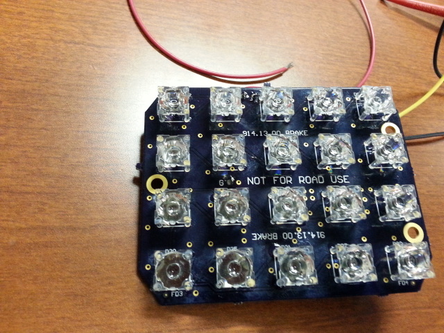
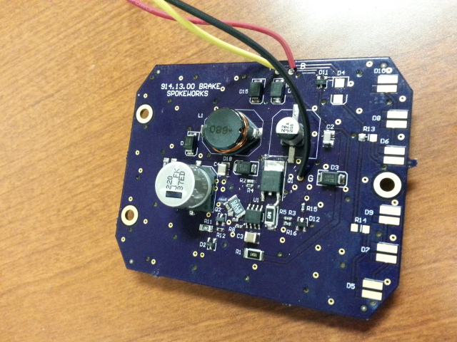
Posted by: CptTripps Jan 14 2014, 12:10 PM
Those look brilliant. Can't wait till a full set is available for purchase.
Posted by: ClayPerrine Jan 14 2014, 12:15 PM
Those look brilliant. Can't wait till a full set is available for purchase.
<insert rimshot here>
Posted by: AE354803 Jan 14 2014, 12:53 PM
Spoke - Cool that you worked on that.
Are you an EE and do you still do desgin/layout work?
I have also always wanted to make a brake light module with a MEMs G-force sensor in it.
If you press the brakes lightly (low G-force) the light comes on like normal.
If you stomp on the brakes (high G-force), the Brakes lights Blink furiously...
Yep, EE with Masters from Lehigh U. I design, lay out, and assemble circuit boards. Most we have completely assembled but others we do by hand.
I laid out and assembled the 5mm LED PCB here. If you want to build something we should talk. I've already done a PCB for another member.
The MEMs sounds cool but I've been concerned lately with complexity with brake circuits with digital logic.
No way! I'm an ME w/ masters from Lehigh. Looks like a nice winter project.
Andy
Posted by: JmuRiz Jan 14 2014, 02:59 PM
Off topic: Lehigh, good wrestling team!
Posted by: Spoke Jan 15 2014, 04:37 PM
These Cree's are super bright. I'm off by a factor of greater than 5 in current.
This is the shadow of the brake setting. It's way way too bright. It's dangerously bright. At 15 feet, one cannot look at this light and its already in the 914 taillight.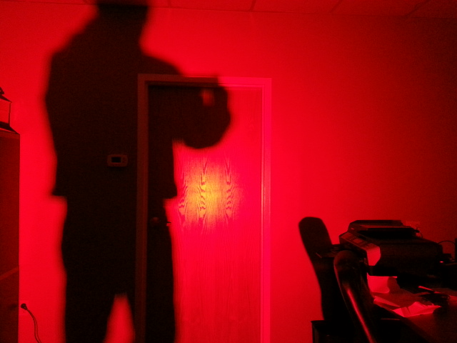
Blinded by the light.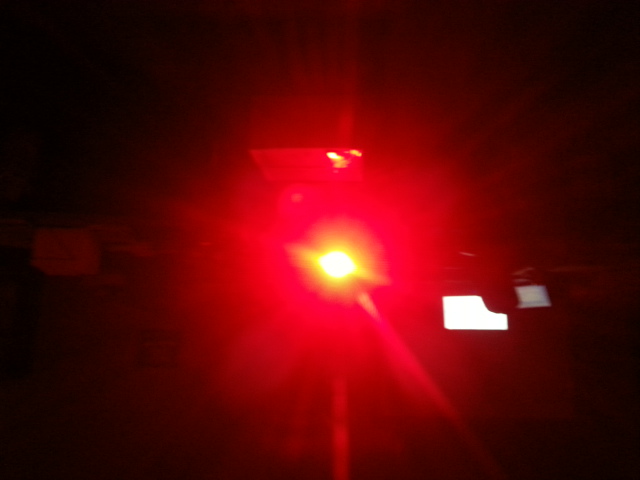
This is the shadow by the taillight setting. It's probably as bright as the brake light should be.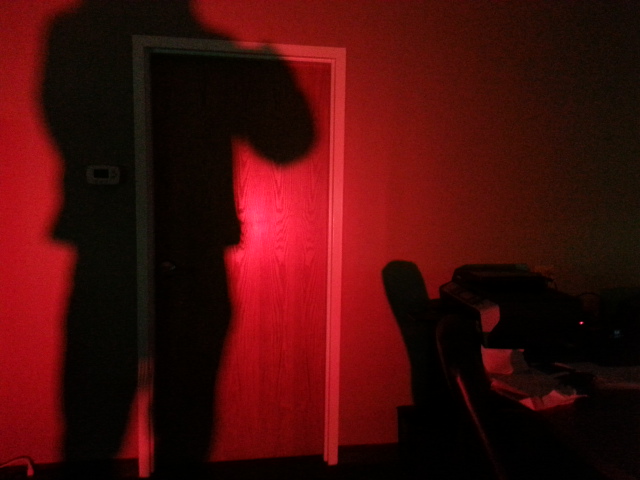
Posted by: Spoke Jan 15 2014, 05:46 PM
OK, I think I have some good levels now. I need to check the relative brightness with the other 5mm LED unit as well as the standard 1157 bulb.
For the taillights shown below, I'm running the LEDs at 2.5mA. For the brakes, I'm running the LEDs at 35mA. I started at 300mA.
The Cree brake unit is now running at 1.4W. This is compared with the standard 1157 bulb at 21W.
Attached image(s)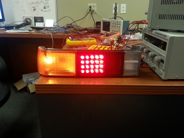
Posted by: Harpo Jan 15 2014, 06:28 PM
Looks good. I'm inclined to believe that they can't be bright enough. Our tail lamps are lower than most cars and if those following us are indeed one car length per 10 MPH then the brightness should not be a problem. IMO
Thanks for the great work! I can't wait to get a set.
DAvid
Posted by: CptTripps Jan 15 2014, 07:43 PM
David: That may be true, but there comes a point where you can flash peoples eyes and cause spots where they CAN'T see. That's REAL bad when they're driving behind you. ;-)
Posted by: Spoke Jan 15 2014, 11:11 PM
Looks good. I'm inclined to believe that they can't be bright enough.
I thought the same thing when I started this design. High power LEDs nowadays can put out ridiculous amounts of light.
To compare output levels, I have one board with 63 of the standard 5mm LEDs running about 50mA in each LED. This board with 20 Cree's running 35mA puts out more light than the 63 5mm LEDs.
The test I did today with 200mA produced so much light that was painful to look at. I stood 20 feet away from the board installed in a 914 housing and I couldn't look at it. The shadow produced on the wall looked like a powerful red spotlight.
I will adjust these to be as bright or brighter than any vehicle brake lights I see. The main idea as you point out is to make our 914's be seen under braking.
Posted by: Harpo Jan 18 2014, 07:40 AM
Obviously you have first hand experience with how bright these are and therefore trust your judgment. Looking forward to having this upgrade in my car.
Thanks again
David
Posted by: McMark Jan 18 2014, 08:07 PM
Could you do a few milliseconds of bright flash and then step down to a safe level?
Posted by: r_towle Jan 18 2014, 08:14 PM
Looks good. I'm inclined to believe that they can't be bright enough.
I thought the same thing when I started this design. High power LEDs nowadays can put out ridiculous amounts of light.
To compare output levels, I have one board with 63 of the standard 5mm LEDs running about 50mA in each LED. This board with 20 Cree's running 35mA puts out more light than the 63 5mm LEDs.
The test I did today with 200mA produced so much light that was painful to look at. I stood 20 feet away from the board installed in a 914 housing and I couldn't look at it. The shadow produced on the wall looked like a powerful red spotlight.
I will adjust these to be as bright or brighter than any vehicle brake lights I see. The main idea as you point out is to make our 914's be seen under braking.
Are you doing something for the 911?
Having pulled up behind a few I am concerned the taillights are far to dim
Posted by: Spoke Jan 19 2014, 12:19 PM
Could you do a few milliseconds of bright flash and then step down to a safe level?
Neat idea. Yes, this would be easy to do. How long of brighter flash would be good? 1/10 sec? 2/10 sec?
Posted by: Spoke Jan 19 2014, 08:02 PM
Are you doing something for the 911?
Having pulled up behind a few I am concerned the taillights are far to dim
I plan to do one for the 911. They have really small brake lights.
Here's the latest 914 brake light. I stretched the board vertically to fill the brake light cavity and moved the LEDs to the edges of the board to get a larger light footprint. LEDs shine in the direction you point them. The lenses don't have a very wide dispersion so these will look larger especially at night.
I added the leading edge bright flash when the brakes are applied like Mark suggested.
The circuitry on the back really shrunk since I didn't need all the current the first circuit was designed for. I still use a big ass DPAK FET where I think I could have used a converter with a built-in FET.
Plus I changed from a boost converter to a buck converter. Buck converters are more suitable to handle transients on the brake/taillight wires than a boost converter.
Attached image(s)
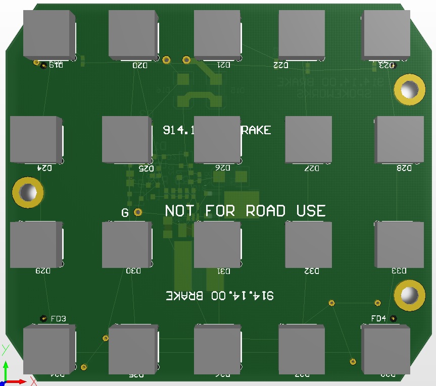
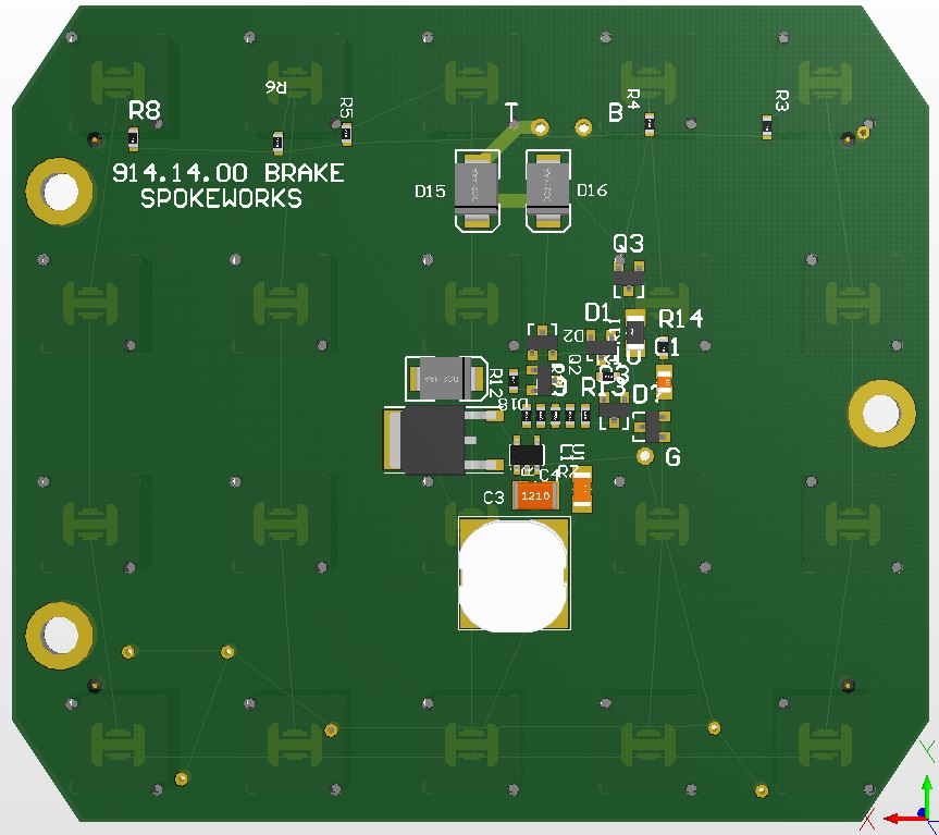
Posted by: Harpo Jan 19 2014, 08:45 PM
Looking good
Posted by: Cairo94507 Jan 19 2014, 09:27 PM
I really like the idea of a brighter flash for a couple milliseconds and then stepping it down to just bright.
Posted by: jcd914 Jan 20 2014, 01:11 PM
Looks good. I'm inclined to believe that they can't be bright enough.
I thought the same thing when I started this design. High power LEDs nowadays can put out ridiculous amounts of light.
To compare output levels, I have one board with 63 of the standard 5mm LEDs running about 50mA in each LED. This board with 20 Cree's running 35mA puts out more light than the 63 5mm LEDs.
The test I did today with 200mA produced so much light that was painful to look at. I stood 20 feet away from the board installed in a 914 housing and I couldn't look at it. The shadow produced on the wall looked like a powerful red spotlight.
I will adjust these to be as bright or brighter than any vehicle brake lights I see. The main idea as you point out is to make our 914's be seen under braking.
There are legal limits on the light output from both brake and running lights, something in the range of 100-300 candela for brake lights in the US.
Jim
Posted by: Speedmster Jan 20 2014, 03:32 PM
Looks good. I'm inclined to believe that they can't be bright enough.
I thought the same thing when I started this design. High power LEDs nowadays can put out ridiculous amounts of light.
To compare output levels, I have one board with 63 of the standard 5mm LEDs running about 50mA in each LED. This board with 20 Cree's running 35mA puts out more light than the 63 5mm LEDs.
The test I did today with 200mA produced so much light that was painful to look at. I stood 20 feet away from the board installed in a 914 housing and I couldn't look at it. The shadow produced on the wall looked like a powerful red spotlight.
I will adjust these to be as bright or brighter than any vehicle brake lights I see. The main idea as you point out is to make our 914's be seen under braking.
There are legal limits on the light output from both brake and running lights, something in the range of 100-300 candela for brake lights in the US.
Jim
I'm not seeing a maximum limit. I see a minimum limit. I'm looking a NHTSA Table IV-a—Effective Projected Luminous Lens Area Requirements. Then again I'm not even near expert on reading regulations. Anybody know how to read this stuff?
Easier version:
http://books.google.com/books?id=K7OqEdViZBkC&pg=PA430&lpg=PA430&dq=Table+IV-a—Effective+Projected+Luminous+Lens+Area+Requirements&source=bl&ots=giHl8sp2Mv&sig=rG9yyynmx6pxFISst0Vuqa8GFac&hl=en&sa=X&ei=FJDdUq2KB5PwyAGjioHgBw&ved=0CDQQ6AEwAQ#v=onepage&q=Table%20IV-a—Effective%20Projected%20Luminous%20Lens%20Area%20Requirements&f=false
NHTSA version:
http://www.fmcsa.dot.gov/rules-regulations/administration/fmcsr/fmcsrruletext.aspx?reg=571.108
Maybe that's why the "NOT FOR ROAD USE" printed on the board.

Posted by: Spoke Jan 20 2014, 04:42 PM
Been contemplating a way to secure the board to the housing with minimal effort.
Mikesmith suggested a clip that would be held in place by the taillight lens and would just clip onto the divider on the housing and the board and thus hold the board in place.
So I used some sheet brass to mock up such a connection.
Here are the pieces. Looks like it will work just fine. I will look into getting these made in plastic or metal.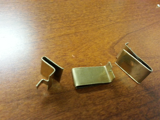
Just insert the clips into the holes in the board.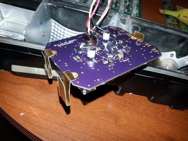
And slide the clips onto the plastic dividers.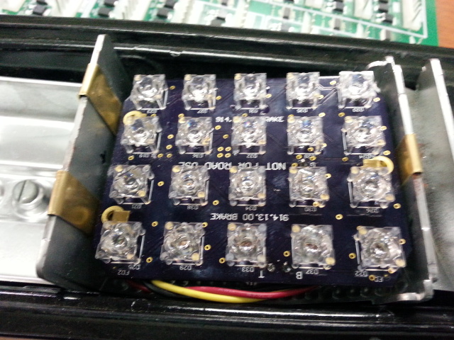
Posted by: CptTripps Jan 20 2014, 06:59 PM
Great work man. That's a seriously great project...expertly executed.
Posted by: monkeyboy Jan 23 2014, 09:20 AM
Beautiful!
Posted by: Spoke Jan 24 2014, 12:04 AM
Here's a comparison of the Cree LED board and the 1157 bulb. The first two flashes are the taillights and the last 3 are brake lights. Quite an improvement over the 1157 bulb.
For braking, the 1157 bulb is burning 21W while the Cree LED board is burning only 1.4W. One can also see the immediate light of the LED vs the 1157 when the brakes are pressed.
I had put in a circuit to flash the brake lights 4 times the intensity for about 1/4 second but it's not working in the car. Worked nicely in the lab with short wires to the power supply. The longer wiring of the vehicle must be slowing the rising edge of the voltage to the lights.
https://www.youtube.com/watch?v=qyFzq9C1hxM
Posted by: Spoke Jan 24 2014, 12:31 AM
This set of LED brake lights is now for sale. This is the only set available with these 5mm LEDs.
I wanted to try these out before I had the Cree LED board going. I've been running these in my car for the last several weeks.
These work well and put out a lot of light. See posts 186 through 196 for the light results.
This is the only set. Just looking to cover my cost at $55 + shipping. Includes 2 boards with pigtails and light bulb bases as shown, and 6 clips.
Real simple installation: pull bulb, insert bulb base, insert clips into boards, clip onto existing enclosure frame.
Respond to this thread if interested in purchase.
Attached image(s)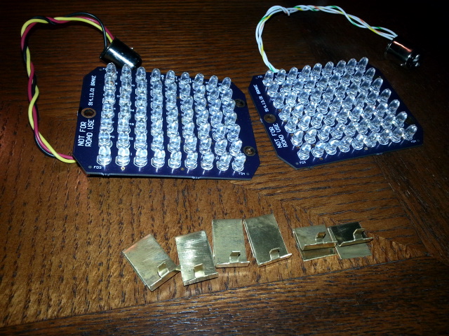
Posted by: Jeffs9146 Jan 24 2014, 01:05 AM
I am in for a set!
Posted by: Speedmster Jan 24 2014, 06:28 AM
This set of LED brake lights is now for sale. This is the only set available with these 5mm LEDs.
I wanted to try these out before I had the Cree LED board going. I've been running these in my car for the last several weeks.
These work well and put out a lot of light. See posts 186 through 196 for the light results.
This is the only set. Just looking to cover my cost at $55 + shipping. Includes 2 boards with pigtails and light bulb bases as shown, and 6 clips.
Real simple installation: pull bulb, insert bulb base, insert clips into boards, clip onto existing enclosure frame.
Respond to this thread if interested in purchase.
Spoke, is there a chance you could shoot a video or take a photo in broad daylight about 20-30 feet behind the car? Interested in how the LEDs preform in the daytime also. Similar to the photo in post #196 that was at night from the rear of your car.
Posted by: Cairo94507 Jan 24 2014, 08:22 AM
Wow- this project is moving forward very nicely. That is looking nice. I too would like to see some video from behind during the daytime. Thanks for the hard work and dedication.
Posted by: Spoke Jan 24 2014, 03:17 PM
Here's some daylight vids.
This one is the Cree LED vs 1157
https://www.youtube.com/watch?v=Ca_TNjqifBw
This one has the Cree LEDs and the 5mm LED board.
https://www.youtube.com/watch?v=1HQjAIiWPz0
Posted by: FlatIV Jan 24 2014, 04:48 PM
Are the Cree LED's red?
Posted by: Speedmster Jan 24 2014, 05:58 PM
Spoke, those look good man! Both Cree and 5mm show pretty good.
I would like to purchase the 5mm LED Lights. PM sent.
Posted by: Spoke Jan 25 2014, 01:47 AM
Are the Cree LED's red?
Yes. The p/n is XBDRED-00-0000-000000701.
Posted by: Spoke Jan 25 2014, 01:59 AM
Just toying around with a different LED pattern. Instead of a grid of 5 x 4 LEDs, what about a box pattern. More like connected lines outlining the brake light.
Attached image(s)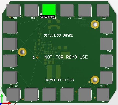
Posted by: mikesmith Jan 25 2014, 02:42 AM
I mixed the box and fill when I was playing with the smart LEDs; at distance it's hard to make the box out - would have worked better with clear tails and double-wide.
Posted by: cary Jan 25 2014, 09:35 AM
I'm in for a pair of 5mm when they're available.
Posted by: Rotary'14 Jan 25 2014, 11:15 AM
Just toying around with a different LED pattern. Instead of a grid of 5 x 4 LEDs, what about a box pattern. More like connected lines outlining the brake light.
How about running lights as the "box" perimeter and the whole thing for brakes? I think that would look cool.
Posted by: Spoke Jan 26 2014, 06:12 PM
Finally got the costs figured out for the 5mm board.
$90 + shipping.
This will include:
2 PCBs with 64 LEDs each.
Pigtail with 1157 base to plug directly into existing bulb socket.
6 clips to mount the boards to existing light housing.
New PCB is larger than the prototype as the LED grid grows by 1 to 64 LEDs in an 8x8 pattern instead of the 7x9 with the LEDs spread out a bit more to provide a larger lighting footprint.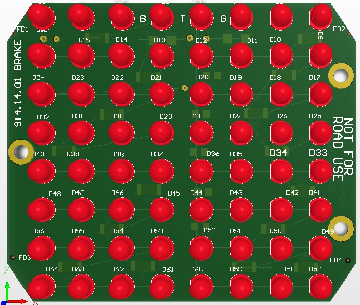
Prototype 5mm PCB shown with pigtail, bulb socket and 6 clips.
Posted by: Kansas 914 Jan 26 2014, 06:26 PM
Finally got the costs figured out for the 5mm board.
$90 + shipping.
This will include:
2 PCBs with 64 LEDs each.
Pigtail with 1157 base to plug directly into existing bulb socket.
6 clips to mount the boards to existing light housing.
New PCB is larger than the prototype as the LED grid grows by 1 to 64 LEDs in an 8x8 pattern instead of the 7x9 with the LEDs spread out a bit more to provide a larger lighting footprint.
Prototype 5mm PCB shown with pigtail, bulb socket and 6 clips.
I am in for a set. Will ordering info be coming soon?
Great looking product, thanks!
Posted by: palmer_md Jan 26 2014, 06:49 PM
Just toying around with a different LED pattern. Instead of a grid of 5 x 4 LEDs, what about a box pattern. More like connected lines outlining the brake light.
How about running lights as the "box" perimeter and the whole thing for brakes? I think that would look cool.
I agree, that might look good if it were not too hard, but probably easier to accomplish with the 5mm board than the Cree board because of the fewer numbers of emmitters.
Posted by: Harpo Jan 26 2014, 06:55 PM
Price sounds good. Sign me up
Thanks
David
Posted by: tomeric914 Jan 26 2014, 07:44 PM
Very well done! I'm in for a set!
Posted by: Zimms Jan 27 2014, 08:22 AM
+1
Posted by: chads74 Jan 27 2014, 09:03 AM
I'll take a set. Where do I send the $$
Posted by: Spoke Jan 27 2014, 11:09 AM
Thanks all for the interest in the brake lights.
Here's how we will do this. I'll wait about a week to see how many sets are needed.
Then I'll order PCBs (will take about 2 weeks to fab) and order parts. At that point I will ask for payment through paypal.
The sets will be built one PCB at a time at my US-based production facility in my basement . Once built and tested they will be shipped.
The clips at this time are hand made from brass sheet and hold the board quite firmly. I hope to get these made out of plastic but that effort is still on-going.
Posted by: monkeyboy Jan 27 2014, 11:45 AM
I will take a set of the 5MM ones as well.
Will you be working your way around to making the whole taillight cluster LED?
Posted by: Chris H. Jan 27 2014, 11:54 AM
I'm in for a set. Wow that video is alarming...how does anyone see us at all with the stock ones ?
Posted by: FlatIV Jan 27 2014, 05:45 PM
One set please.
Posted by: Rleog Jan 27 2014, 06:32 PM
In for 1 set.
Posted by: 914coop Jan 27 2014, 07:02 PM
I'll take a set.
Thank's Irv
Posted by: sportlicherFahrer Jan 27 2014, 08:58 PM
+1
Posted by: cconcepcion Jan 31 2014, 09:32 PM
I'm in for a set as well.
Posted by: Cairo94507 Feb 1 2014, 07:49 AM
You know I am going to have a set of these for my car. We just are not ready for them yet...
Posted by: dw914six Feb 1 2014, 08:25 AM
Looks great. I will take 1 set.
Posted by: Spoke Feb 5 2014, 08:43 PM
An update on the 5mm LED lights; I have been testing the prototype set of 5mm LEDs to understand the temperature rise when the brakes are applied. This is the highest power dissipation state and will generate the highest temperatures.
The prototype with 63 LEDs and maximum current runs very hot. I've measured temperatures over 100C which is way too high. I've cut the current down a bit but the circuit still runs very hot.
My goal is to keep the temps about 40C above ambient. To do this, I had to turn off 12 of the LEDs to reduce the power dissipation. Now the circuit runs around 60C (room temp is 23C).
Even with the reduced current and number of LEDs, the circuit still puts out way more light than the 1157 bulb and is on par with the CREE board.
With this info, I decided to reduce the number of LEDs to 48 which will still give a wall of light. The board is about 1/4 inch taller than the prototype should work well.
I need to test this board out so I will build only 1 pair to begin with so I can evaluate the thermal performance of the unit.
Sorry for the delay but I need to make sure these work well before doing any mass building.
Attached image(s)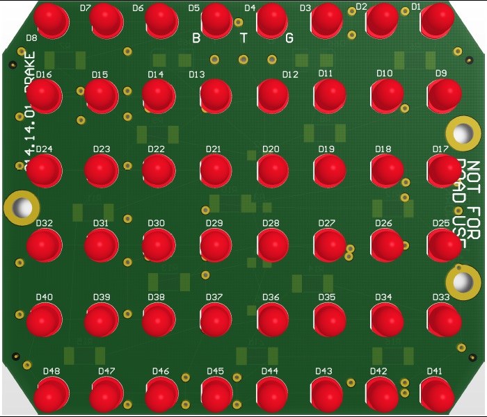
Posted by: smj Feb 21 2014, 03:24 AM
Glad to hear you're double checking the heat dissipation. I need a set, just want to see which variant you actually get fabbed.
Posted by: Spoke Feb 23 2014, 07:49 PM
I built one PCB with high power Cree amber LEDs to use as turnsignals.
The PCB was mounted in the turnsignal housing using brass clips. The one on the end is quite long and doesn't hold the board as tight as the brake light.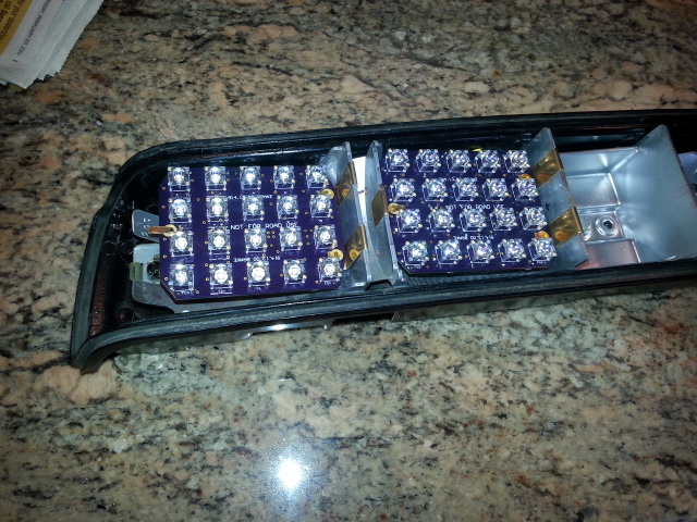
This pic shows the skew of the boards in the housing so that they're pointed directly behind the car. If made on one board, the brake lights would be quite deep in the housing.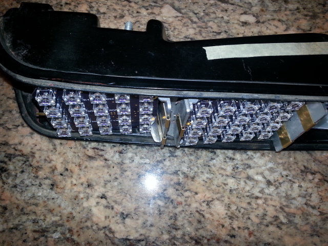
Posted by: Spoke Feb 23 2014, 07:57 PM
When I built the Cree amber board, I didn't think the LEDs were quite as bright as the red LEDs so I increased the current to 70ma (brake lights are at 40mA).
Here's a comparison of the original turnsignal bulb and the amber Cree LEDs.
I think I went too far with 70ma. It is very bright.
https://www.youtube.com/watch?v=Mxb6IvHO_SA
Here's what the turnsignal light looks like with just parking lights on. I'm only running about 3ma in the LEDs. These put out about as much light rearward as the little side light does.
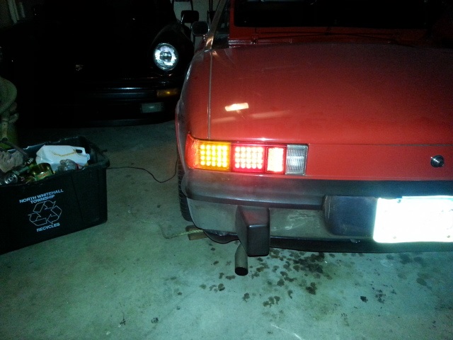
Posted by: Spoke Feb 23 2014, 08:01 PM
About the 5mm boards, I found a Cree LED which should put out as much light as the Vishays but with a wider 1/2 power angle. I ordered the Cree LEDs and will build one more board and test it. Sorry for the delay but I want to make sure the board is a good as can be for everyone.
Posted by: Cairo94507 Feb 23 2014, 08:08 PM
I just love that you are addressing the brake and turn signals will you also do the taillight? That way the whole rear will be LED's.
I am definitely down for a set of these when you get the final version done and Scotty tells me it is time for taillight assembly.
Posted by: monkeyboy Feb 24 2014, 10:31 AM
I am even more excited now.
I would recommend front turn signals, and the option of the side lights as well.
I would love to go full LED. Headlights, and Fog Lights included. I will one day.
Posted by: cary Feb 25 2014, 08:14 AM
I'm in for a set when your ready.
Posted by: barebrad Feb 25 2014, 11:59 AM
+1 (Brake)
Posted by: Kansas 914 Feb 25 2014, 12:05 PM
I would love to be able to "show off" my LED taillights at Route 66 Classic March 21st.... But I will be patient.
It would go well with my LED front turn signals.
https://www.youtube.com/watch?v=PAgCELfdMeM
Posted by: shawn914 Feb 25 2014, 05:59 PM
Will take a set when ready.
Posted by: kid914 Feb 25 2014, 06:09 PM
might be in for 1
thank
Posted by: Cairo94507 Feb 25 2014, 06:25 PM
I have to agree with monkey boy - it would be crazy cool to be able to convert all of the lights to LED! I would totally be in for that.
Posted by: Vacca Rabite Feb 25 2014, 07:15 PM
Spoke, I'm in for a set when you are ready. These are fantastic.
Posted by: Harpo Feb 26 2014, 05:39 AM
Very impressive
Posted by: r_towle Feb 26 2014, 07:03 PM
I am in for at least one set.
When are you going to get this done slacker???
Posted by: Spoke Feb 27 2014, 11:32 AM
I am in for at least one set.
When are you going to get this done slacker???
I just received some new 5mm LEDs from Cree that have a wider 1/2 power angle and run at less current. I'll build one PCB this weekend to try it out.
Power dissipation and resulting temperature rise are what I've been struggling with on this project with the 5mm LEDs.
The parking light setting is no problem. The brake light setting is the issue.
The goal is to manage the heat when the driver stands on the brake indefinitely and not have the unit fail. Both taillight housings on my car have melted plastic above the brake bulb from the heat of the bulb when standing on the brakes like in stopped traffic.
If these work out I can go to fab with the PCB and get things moving.
Posted by: JmuRiz Feb 27 2014, 01:21 PM
Glad you are experimenting to see what style/configuration works best in terms of light/heat. I'm waiting to see what is the "best" configuration, but I'm sure I'll be in the market when the design is finalized.
Posted by: r_towle Mar 1 2014, 06:41 PM
Have you considered replacing the melted area with a piece of metal as part of the solution?
Posted by: Spoke Mar 2 2014, 11:56 PM
I built another 5mm LED board with Cree C503-AAN-CY0B LEDs which have significant light output. The goal was to run the LEDs at about 1/2 the current of the original Vishay 5mm LEDs.
The lower current would allow the boards to run at much lower current/power/temp while putting out the same light.
Only 51 LEDs were installed and run at about 25ma. The results were very encouraging. The light output is equal to the high power LED Cree boards which I use to compare light output.
The light dispersion of these 5mm LEDs is much better than the Vishays and just about equal to the high power LED Crees.
With the original 5mm LED boards with Vishay LEDs I determined that just over 7W of power would give a temperature rise of about 40C. This board dissipates just over 6W so temperature rise is around 30C.
Attached image(s)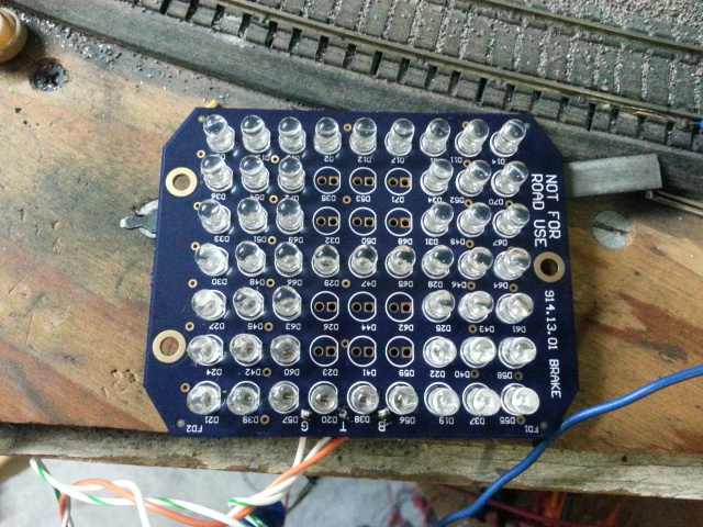
Posted by: Spoke Mar 3 2014, 12:11 AM
OK, I'm finally ready to move forward with a PCB based on the 5mm Cree LEDs. Results were good with my test board.
This board will run at even less power as I will stack 4 LEDs in series instead of 3 like the original board.
This board will have 56 LEDs running at 25ma for the brake setting and about 4ma for taillight. The board will burn about 4.5W when lit for brake. I estimate a temperature rise of about 25C which is fantastic.
I should be done with the layout this week and hopefully go to fab next week.
The image below shows 8 LEDs facing to the left which would be populated if this board were used as a turnsignal replacement. The 8 LEDs would illuminate the side marker.
Cree also manufactures an amber LED in this series. I will build a couple of these with the amber LEDs to compare the output before offering these for sale.
Attached image(s)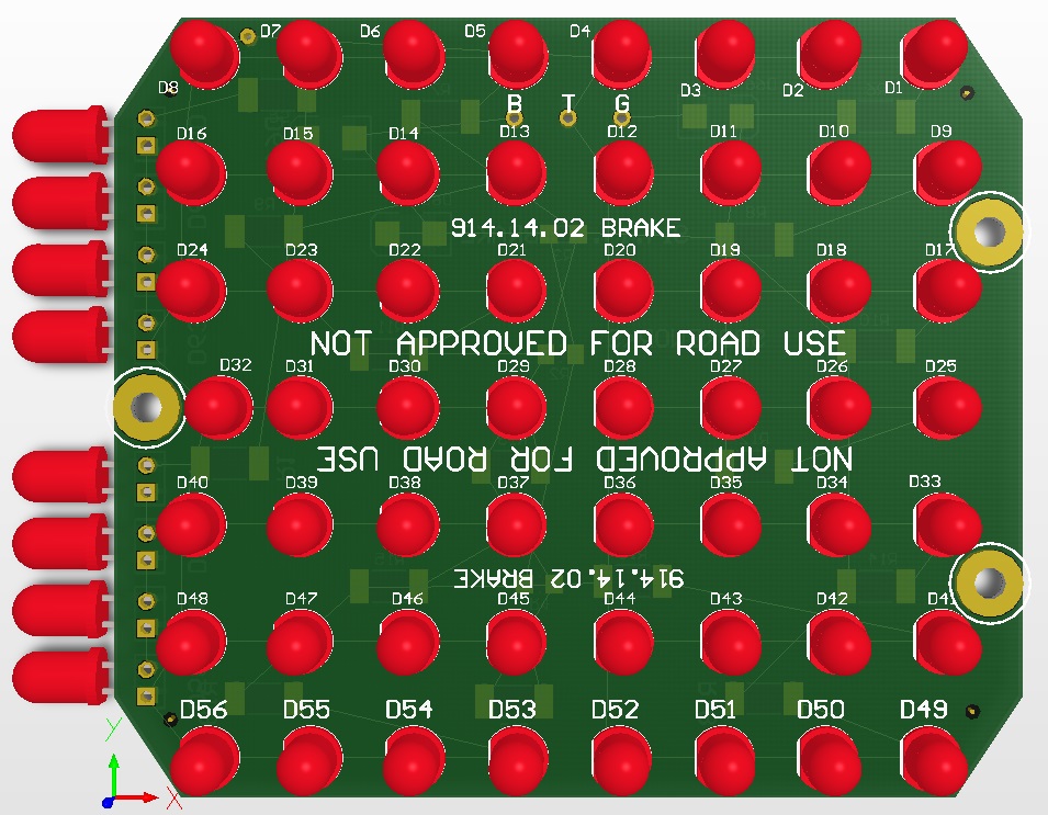
Posted by: Spoke Mar 3 2014, 12:15 AM
Have you considered replacing the melted area with a piece of metal as part of the solution?
I haven't done anything with the affected area. The cracks aren't bad but do show the signs of burning 20W in a bulb only 1-1/2 inches below the housing. I now have the high power Cree LED boards installed so there will be no more heating of the housing.
Posted by: Spoke Mar 3 2014, 12:25 AM
If you want a spare set of taillight housings, just ask.
Mark, I'd like to take you up on the offer of a housing. I only need one since the boards need to be interchangeable left to right.
I want to investigate doing the brake and turnsignal on one board.
Issues include:
1) The internal housing separators will have to be cut away.
2) A divider between turnsignals and brakes need to provided.
3) PCB fastening to the remaining parts of the housing needs to be worked out.
The board will have to be at an angle such that the LEDs point directly behind the vehicle. The needed angle can be seen below. With the edge of the turnsignal PCB at the outer perimeter of the housing, the brake LEDs will be quite a bit deeper in the housing.
Attached image(s)

Posted by: Speedmster Mar 3 2014, 07:18 AM
Spoke,
As I mentioned in a PM, I have received the prototype brake light boards. Dad and I disassembled his taillights yesterday and gave one a try to compare OEM with the LED board. Big difference. They look good! Dads car is 98% original 914-6 and the taillights gaskets are shot and reflectors have started flaking their reflective chrome finish off. The brass mounting clips are perfect! One observation, it was a bit challenging to get the bulb socket end in. When installing a new bulb the glass itself gives you leverage to push and turn in. Without the glass what has been your technic?
These are pretty cool and when we get our buckets cleaned up and put together we will post photos.
If anyone has an extra set of taillight buckets, reflectors, and lens that are still useable I would be interested. We would like to keep dads original set OEM and have a set we can dedicate to LED.
Posted by: Spoke Mar 3 2014, 08:31 AM
Spoke,
As I mentioned in a PM, I have received the prototype brake light boards. Dad and I disassembled his taillights yesterday and gave one a try to compare OEM with the LED board. Big difference. They look good! Dads car is 98% original 914-6 and the taillights gaskets are shot and reflectors have started flaking their reflective chrome finish off. The brass mounting clips are perfect! One observation, it was a bit challenging to get the bulb socket end in. When installing a new bulb the glass itself gives you leverage to push and turn in. Without the glass what has been your technic?
These are pretty cool and when we get our buckets cleaned up and put together we will post photos.
If anyone has an extra set of taillight buckets, reflectors, and lens that are still useable I would be interested. We would like to keep dads original set OEM and have a set we can dedicate to LED.
Glad you got them lit up. I remembered that I didn't mention how to install the bulb bases in the sockets. They can be tricky. I've gotten so used to them cause I've installed and removed these a hundred times.
The trick is to put your finger in the socket like in the pic. This will give enough pressure and friction to install.
Attached image(s)
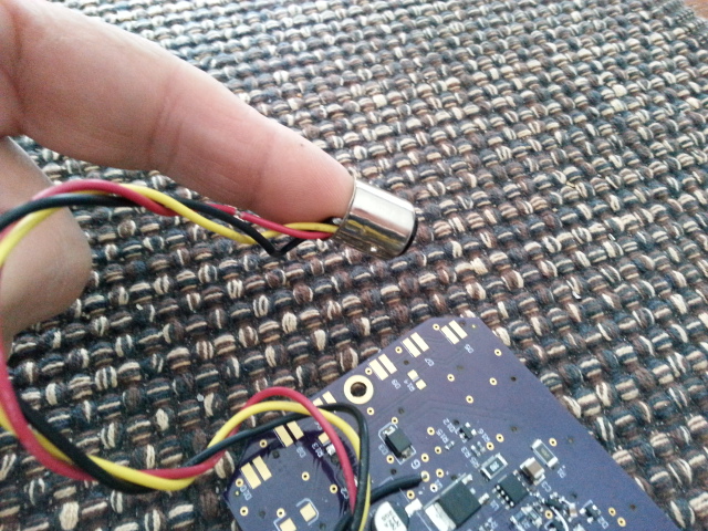
Posted by: CptTripps Mar 3 2014, 09:27 AM
Note: That's the first time that anyone has ever said "Just put your finger IN the socket to install it."
Bravo!
Posted by: Spoke Mar 10 2014, 03:26 PM
Boards were ordered last week.
Will have the bare boards in 2 weeks. Should be able to start deliveries a week or 2 later.
Cheers
Posted by: orthobiz Mar 10 2014, 06:47 PM
Is the video with most current incarnation of the lights posted? Seems like some of your posts were showing the evolution of your design. Thanks,
Paul
Posted by: Spoke Mar 10 2014, 07:01 PM
Is the video with most current incarnation of the lights posted? Seems like some of your posts were showing the evolution of your design. Thanks,
Paul
The video shows the rev 1 5mm board on the passenger side. The rev 2 5mm board will use more efficient LEDs (less current, similar intensity, wider 1/2 power angle) and will run cooler.
I built one rev 1 5mm board with the efficient LEDs. That board is shown in a couple of posts ago in post 285. This one used 51 LEDs whereas the rev 2 5mm board will use 56 LEDs. The light output for the 51 LEDs was on par with the high power LED board which is my standard.
I can do a video with the 51 LED board later this week.
Posted by: Speedmster Mar 10 2014, 07:33 PM
Glad you got them lit up. I remembered that I didn't mention how to install the bulb bases in the sockets. They can be tricky. I've gotten so used to them cause I've installed and removed these a hundred times.
The trick is to put your finger in the socket like in the pic. This will give enough pressure and friction to install.
That is exactly what we ended up doing.
While we had the taillights apart our OCD kicked in and we had some cleaning to do and ordered new seals. The OEM style bulbs (not LED) the car came with had slightly melted the bucket and reflector. Dad seems to remember back in the 80's having a brake light on the left side that stuck on one time. He thinks that is what did it.
I have the rev 1 5mm (I think, correct me if I'm wrong Spoke) and they are a very big improvement in both day and night IMO.
Posted by: Zimms Mar 11 2014, 07:17 AM
Spoke,
Do you have an idea of the cost?
Thanks,
Mark
Posted by: Spoke Mar 11 2014, 01:29 PM
Spoke,
Do you have an idea of the cost?
Thanks,
Mark
$90 + shipping.
This will include:
2 PCBs with 56 LEDs each.
Pigtail with 1157 base to plug directly into existing bulb socket.
6 clips to mount the boards to existing light housing.
Posted by: Zimms Mar 11 2014, 01:34 PM
Thanks! Let us know where and when you want $$$
Posted by: monkeyboy Mar 11 2014, 02:37 PM
Spoke,
Do you have an idea of the cost?
Thanks,
Mark
$90 + shipping.
This will include:
2 PCBs with 56 LEDs each.
Pigtail with 1157 base to plug directly into existing bulb socket.
6 clips to mount the boards to existing light housing.
So these are brake lights only at this time? Turn signals upcoming, or can we buy two sets of these and convert all at once?
Posted by: orthobiz Mar 12 2014, 02:51 PM
Is the video with most current incarnation of the lights posted? Seems like some of your posts were showing the evolution of your design. Thanks,
Paul
The video shows the rev 1 5mm board on the passenger side. The rev 2 5mm board will use more efficient LEDs (less current, similar intensity, wider 1/2 power angle) and will run cooler.
I built one rev 1 5mm board with the efficient LEDs. That board is shown in a couple of posts ago in post 285. This one used 51 LEDs whereas the rev 2 5mm board will use 56 LEDs. The light output for the 51 LEDs was on par with the high power LED board which is my standard.
I can do a video with the 51 LED board later this week.
Thanks, much appreciated.
Paul
Posted by: Spoke Mar 12 2014, 04:00 PM
So these are brake lights only at this time? Turn signals upcoming, or can we buy two sets of these and convert all at once?
The board itself can be used as a brake or turnsignal as shown below.
I did this with the high power LED boards on my car. The brake PCB uses red LEDs whereas the turnsignal PCB uses amber LEDs to match the Euro amber turnsignal lenses. Same PCB, different LEDs. The turnsignal PCB also has side emitting LEDs to give light for the side marker.
The rev 2 5mm PCBs also have provision for side LEDs and should be a lot brighter than the side emitting LEDs I used on my car. These can be used for turnsignals too.
For Euro lens with amber turnsignal lens, I've ordered some amber 5mm LEDs in the Cree family and will build a couple of these to see how bright they are. If ok, I can offer those as well. I need to test them first.
For US lens with red turnsignal lens, red LEDs would be used for turnsignals. This would be just a build option as the bulb bases would be different than the brakes.
I want to take this a step further and make one board for both brake and turnsignal. This requires a lot of engineering to make sure it works. The existing inner housing would have to be cut out and other means of fastening the boards to be found.
The angle of the board would have to be the same as below so the brake portion would sit very deep in the housing. A divider would have to be included to keep the brake light from bleeding into the turnsignal light and visa versa. McMark is sending me a spare housing that I can experiment with.
Attached image(s)


Posted by: r_towle Mar 12 2014, 08:06 PM
Should I bring some cash to Hershey for a full set of euro tai lights this year?
Rich
Posted by: Spoke Mar 12 2014, 09:34 PM
Should I bring some cash to Hershey for a full set of euro tai lights this year?
Rich
Quite possibly, the timing is right; will have PCBs in 2 weeks. I gotta test the amber turnsignal LEDs first.
I did the amber turnsignal for my car with the high power LEDs and initially thought they weren't bright enough so I increased the current from 35ma for the red LEDs to 75ma for the amber LEDs. Whoa, the amber LEDs are way too bright at 75ma. They're blindingly bright. 35ma may have been ok.
Got to see the 5mm amber LEDs before making them available.
I need to get a good lux meter. Anyone have a suggestion for a good, affordable lux meter?
Posted by: r_towle Mar 12 2014, 09:37 PM
No kidding, there is an app for that
Go to the apple app store or the droid google play store.
rich
Posted by: Zimms Mar 13 2014, 08:31 AM
If you need another tail light housing, I think I have one I can donate to the cause. I'll check later today.
Posted by: effutuo101 Mar 13 2014, 03:08 PM
I would prefer a longer board to handle both brake, running and turn.
saw some cool ones for the Mercedes G class on wheeler dealer last night.
Posted by: monkeyboy Mar 13 2014, 03:57 PM
So these are brake lights only at this time? Turn signals upcoming, or can we buy two sets of these and convert all at once?
The board itself can be used as a brake or turnsignal as shown below.
I did this with the high power LED boards on my car. The brake PCB uses red LEDs whereas the turnsignal PCB uses amber LEDs to match the Euro amber turnsignal lenses. Same PCB, different LEDs. The turnsignal PCB also has side emitting LEDs to give light for the side marker.
The rev 2 5mm PCBs also have provision for side LEDs and should be a lot brighter than the side emitting LEDs I used on my car. These can be used for turnsignals too.
For Euro lens with amber turnsignal lens, I've ordered some amber 5mm LEDs in the Cree family and will build a couple of these to see how bright they are. If ok, I can offer those as well. I need to test them first.
For US lens with red turnsignal lens, red LEDs would be used for turnsignals. This would be just a build option as the bulb bases would be different than the brakes.
I want to take this a step further and make one board for both brake and turnsignal. This requires a lot of engineering to make sure it works. The existing inner housing would have to be cut out and other means of fastening the boards to be found.
The angle of the board would have to be the same as below so the brake portion would sit very deep in the housing. A divider would have to be included to keep the brake light from bleeding into the turnsignal light and visa versa. McMark is sending me a spare housing that I can experiment with.
I want a set of US Brake and turn signals, but I am happy with them just the way they are. I do not want to modify the housings or cut anything.
They honestly look great to me, and it's reversible if you every want to.
Posted by: zymurgist Mar 15 2014, 07:59 AM
Should I bring some cash to Hershey for a full set of euro tai lights this year?
Rich
Quite possibly, the timing is right; will have PCBs in 2 weeks. I gotta test the amber turnsignal LEDs first.
I would be down for a set also!
Posted by: cary Mar 15 2014, 08:17 AM
I'm in for a set.
Posted by: clapeza Mar 15 2014, 08:28 AM
I'm in for a full set, brakes and US spec turn signals, once they're available.
Posted by: CptTripps Mar 15 2014, 10:03 AM
You know I'm in for a set. Not sure what I was planning will work, so this is an awesome backup.
Well done!
Posted by: rnellums Mar 15 2014, 01:22 PM
I would like a set!
Posted by: JRust Mar 15 2014, 01:26 PM
I'd like a set of both. Euro & US versions. I like the separate boards for each. Thanks for doing this. Glad to see it coming to fruition
Posted by: Spoke Mar 16 2014, 07:33 PM
This video and pic are with the 5mm rev 1 board with the Cree LEDs. These are the LEDs which will be on the rev 2 boards. This board has 51 LEDs whereas the rev 2 boards will have 56 LEDs.
The light output is quite good with good dispersion. Like many LEDs, the light is very directional. This is why it is important for the board to be mounted 90 degrees from the centerline of the car. We want all this light pointed directly at cars behind.
The first couple of blinks are the brake lights. The last flash are the taillights. The car is about 6 feet from the garage door.
https://www.youtube.com/watch?v=gewM-W8bQ9M
Here's a pic of the taillights from behind the car. That's also an amber LED board on the left side with the LED taillight.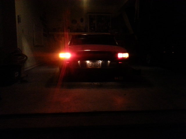
Posted by: Chris H. Mar 16 2014, 08:19 PM
Looks great. I want a set of brakes and us spec turns signals. Happy with them just as they are as separate boards also, I don't need them on one board.
Posted by: Spoke Mar 21 2014, 08:06 PM
Rev 2 boards have been shipped from the fab house. I should have them by midweek. Also ordered all components and empty bulb bases. Assembly should start by next weekend. 


I rigged the 5mm rev 1 board to my 930 to see how much improvement in light output over the standard bulb. Board didn't fit so I aimed it as close as possible to the rear of the car and put the taillight lens in front of it.
Looks like a good improvement over the 1157 bulb in the 930. If you have sound on you can hear the 930 idling. Sounds much better in person.
I think I'll use the same 56 5mm LED pattern like the rev 2 boards for the 911. Gotta figure out a way to secure the board in the 911 brake housing.
https://www.youtube.com/watch?v=GPmOGq8RjH8
Posted by: rnellums Mar 22 2014, 07:05 PM
I am in for a full US spec set!
Posted by: kid914 Mar 22 2014, 08:22 PM
I must have missed the price....?
looks very tho
Posted by: Spoke Mar 23 2014, 11:16 AM
I must have missed the price....?
looks very tho
$90 + shipping.
Update: more materials arrived.
BAY15D are for the brake light.
BAY15S and BAY9S for the turnsignal.
Attached image(s)
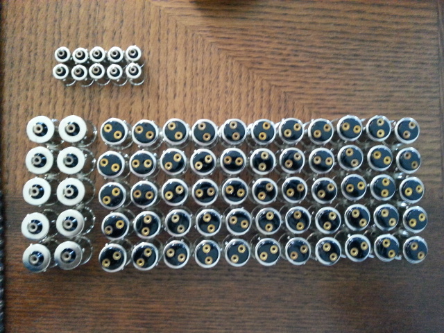
Posted by: r_towle Mar 23 2014, 01:23 PM
Will I need to modify the turn signal housing?
I never heard your conclusions on that....
Posted by: Spoke Mar 23 2014, 02:14 PM
Will I need to modify the turn signal housing?
I never heard your conclusions on that....
The goal is to not make any modifications to the housing. I have a solution now but not real happy with it.
You can see below that the inside uses 2 clips on the divider and secures the board well to the divider like the brake light.
Unlike the brake light, there is nothing but open space on the outside of the turnsignal light. So I've got a clip going to the indentation in the reflector for the side light but the clip is long and does not give good up and down stability.
I've made the rev 2 board a bit taller so it may fit more snugly top-bottom than the rev 1 high power LED board shown here and maybe this type of clip will be ok. I'll know better when I get the rev 2 boards in hand.
If anyone has ideas on how to secure the outside of the turnsignal boards I'm all ears.
Attached image(s)
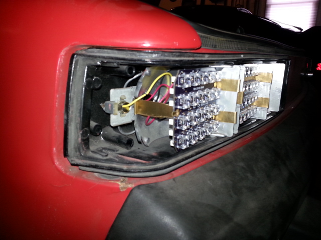
Posted by: r_towle Mar 23 2014, 02:22 PM
Describe the problem with pics....you might get some ideas.
For me, I cannot figure out what you are talking about yet
Posted by: Spoke Mar 23 2014, 06:04 PM
Here's more of a close-up of the clip.
The clip connects to the reflector and is about 1.5 inches to the PCB. OK support horizontal but allows quite a bit of movement up and down.
Attached image(s)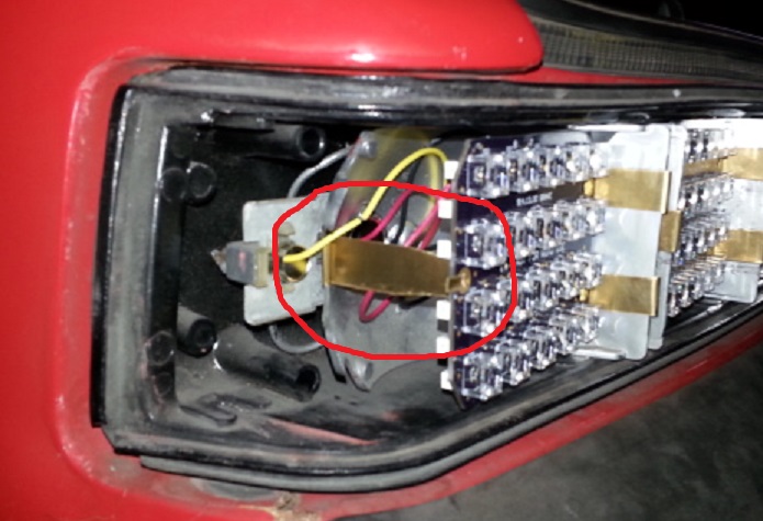
Posted by: db9146 Mar 23 2014, 08:41 PM
Would it be possible to use a couple of small "v"-shaped spring clips at the top and bottom of the boards to hold them in place vertically? If you lay the clips on their side like wedges, it seems that might do the trick and still not require permanent modification to the housing.
Posted by: 7TPorsh Mar 24 2014, 12:05 PM
how about some small rubber pads or bumpers on the top and bottom...weather seal?
Posted by: CptTripps Mar 24 2014, 12:17 PM
What about a triangle with 2 small bends. Two holes would mount to the bucket, the other to the board.
Like this...
Attached image(s)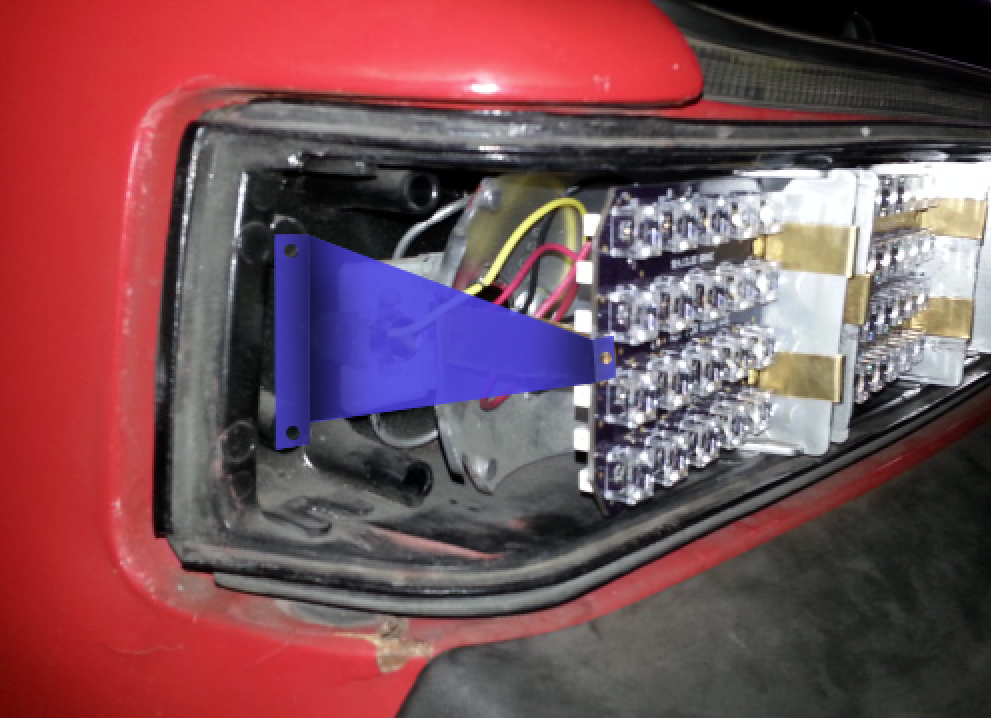
Posted by: JmuRiz Mar 24 2014, 02:13 PM
Now you're talkin' I like that bracket idea.
Posted by: Spoke Mar 24 2014, 08:20 PM
Would it be possible to use a couple of small "v"-shaped spring clips at the top and bottom of the boards to hold them in place vertically? If you lay the clips on their side like wedges, it seems that might do the trick and still not require permanent modification to the housing.
Interesting idea. Something similar to this is used on recessed lighting rings. I didn't think about securing on the edges.
how about some small rubber pads or bumpers on the top and bottom...weather seal?
A rubber dot with a slot to hold the board in it would work. Although I made the rev 2 boards with literally zero play on the top and bottom. Like db's above, I like the idea of edge securing.
What about a triangle with 2 small bends. Two holes would mount to the bucket, the other to the board.
This looks like it would work. One thing though, what about the side lens that is missing on my housing? Are those glued in or just sitting in the slot?
Posted by: CptTripps Mar 25 2014, 07:23 AM
What about a triangle with 2 small bends. Two holes would mount to the bucket, the other to the board.
This looks like it would work. One thing though, what about the side lens that is missing on my housing? Are those glued in or just sitting in the slot?
I'll look tonight, but you could likely make a shield with a small piece of plastic. Another thought would be to have a few LEDs on the triangle piece, so the side of the light would illuminate as well. Really there's no down-side to having extra lighting on the side to show that you're turning.
Posted by: Spoke Mar 25 2014, 09:06 PM
Waiting for the brake PCBs to be delivered..Tomorrow
Just can't stop drawing pictures. Wonder where this one goes?
The white LEDs will blank out when the Amber LEDs flash.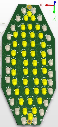
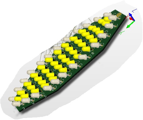
Posted by: CptTripps Mar 26 2014, 06:58 AM
Now you're talking....
Love it!
You could also do a version with the top half in yellow and the bottom in white. Like the "Euro" lenses...without the need for the lens.
Posted by: Cairo94507 Mar 26 2014, 06:59 AM
Excellent! I can see that my car will be all LED equipped when the time comes. On the fronts will you do a version for the euro lens too?
Posted by: JmuRiz Mar 26 2014, 08:02 AM
Re: Front turns...
Like the others said...if you make a euro style with the bottom running light white and on when parking lights and headlights are on...and the flasher above, it would be perfect!
I'm excited about the front/back LED lights, they are the way to go to be seen.
I still need to order some 356 ones, then I'll order your 914 ones when I put my car back together!
Posted by: Chris H. Mar 26 2014, 08:33 AM
Waiting for the brake PCBs to be delivered..Tomorrow
Just can't stop drawing pictures. Wonder where this one goes?
The white LEDs will blank out when the Amber LEDs flash.
Always on running lights in white around the outer part?
Posted by: Spoke Mar 26 2014, 02:50 PM
Always on running lights in white around the outer part?
That's what I would like to do with the lights. This would give the 914 a cool oval running light signature.
When turn signals are on, these would blank out until the turnsignals go off.
Boards are in. Let the fun begin.
Attached image(s)
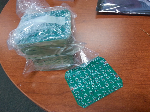
Posted by: porsche_dreamer Mar 26 2014, 03:32 PM
Cant wait to see these! WANT!
Posted by: timothy_nd28 Mar 26 2014, 03:46 PM
Very impressive Which board factory did you use?
Posted by: Spoke Mar 26 2014, 04:03 PM
Very impressive
Which board factory did you use?Thanks.
We use Sierra Circuits quite a bit. Quick turns and longer at reasonable prices.
Had a chance to build one light tonight. I did an amber turnsignal to see how it looks. No pics right now.
Power dissipation is exactly what I expected. Temp rise is very manageable at about 25C.
Posted by: ThePaintedMan Mar 26 2014, 04:25 PM
The 911 guys are going to start hating us when these puppies start rolling out. Very thankful to have someone as talented as you Spoke (and Tim, Rick, Scotty, Joe, Mark, Chris, etc... the list goes on and on) - this stuff boggles my mind.
Posted by: timothy_nd28 Mar 26 2014, 06:06 PM
Very impressive
Which board factory did you use?Thanks.
We use Sierra Circuits quite a bit. Quick turns and longer at reasonable prices.
Had a chance to build one light tonight. I did an amber turnsignal to see how it looks. No pics right now.
Power dissipation is exactly what I expected. Temp rise is very manageable at about 25C.
Thanks, I might give Sierra Circuits a try. I've been messing around with a prototype tachometer board that will replace the old tired control.
Posted by: Spoke Mar 26 2014, 07:39 PM
Very impressive
Which board factory did you use?Thanks.
We use Sierra Circuits quite a bit. Quick turns and longer at reasonable prices.
Had a chance to build one light tonight. I did an amber turnsignal to see how it looks. No pics right now.
Power dissipation is exactly what I expected. Temp rise is very manageable at about 25C.
Thanks, I might give Sierra Circuits a try. I've been messing around with a prototype tachometer board that will replace the old tired control.
Sierra is good if you have a quantity of boards to make otherwise it is expensive for just a couple of boards.
If you want to do a couple of boards, try Osh Park. I used them for my prototype LED boards. Very reasonable for small quantities.
I built a small board (1 inch x 0.5 inch) for a 914world member and it was only a couple of dollars for 3 boards. They get small orders like this and my LED taillights and assemble enough to make a panel then go to fab. Turn around time was like 2 weeks.
Posted by: timothy_nd28 Mar 26 2014, 08:08 PM
I used International Circuits for my last production run, great company but they whack you for doing anything less than 100 boards. I'll try Osh Park for my first 5 boards. Any idea where to source an air core movement motor? You would think these would be easy to find 
Posted by: smj Mar 26 2014, 09:26 PM
Spoke, given that you're still testing some variant builds and such, might make sense to start a new thread when you've locked it down and are ready for orders.
Just a thought, and apologies if it's already been suggested/stated.
Posted by: Spoke Mar 31 2014, 11:44 AM
Spoke, given that you're still testing some variant builds and such, might make sense to start a new thread when you've locked it down and are ready for orders.
Just a thought, and apologies if it's already been suggested/stated.
Good idea. I think I will do that for the next batch. I believe enough folks have stepped up for this batch of 50 boards such that all boards are accounted for. The next will be a group buy as I buy the boards in quantity.
I'm building these boards one at a time so I can't fill all orders at once. I will contact each person in the order of when they asked for a set.
I'm working with CptTripps for the securing clips so I sent a full 4-board set to him to work with:
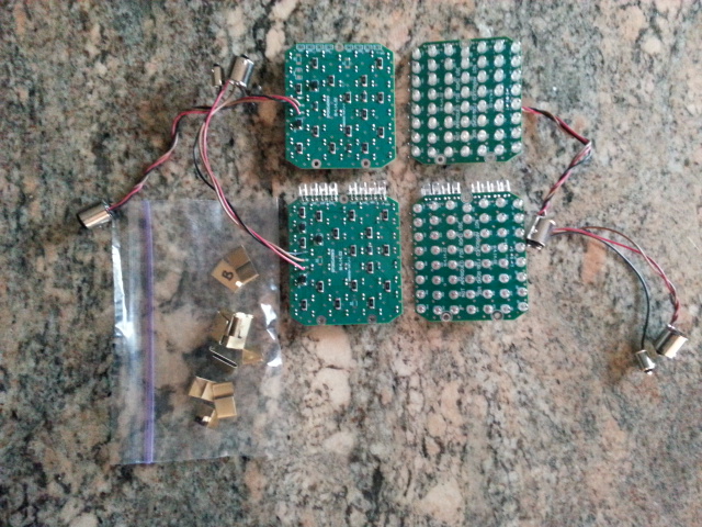
I have 4 sets of brake lights assembled and tested. Need to add the bulb bases and securing clips. These likely will be ready for shipment this weekend. I will contact guys who already responded to this thread for interest in brake lights.
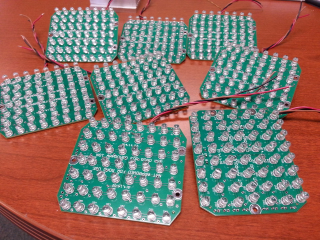
Posted by: CptTripps Mar 31 2014, 11:52 AM
I JUST got notification that they're at my UPS box, so I'll try to dig into it tonight. As soon as I can figure out the right sizing for the triangle clip piece, I'll make a few up and send them your way to ship with the orders.
May take me a day or so...but I'll get to it.
Posted by: CptTripps Apr 1 2014, 04:30 PM
I believe I figured out a solution.
Using some old copper I had, I crafted a piece to go up from one of the clips, and into the hole on the board. This SHOULD do the trick.
Spoke: Before I power this up, is there an issue with this piece being grounded?
Attached thumbnail(s)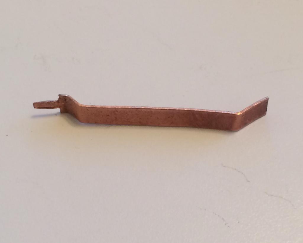
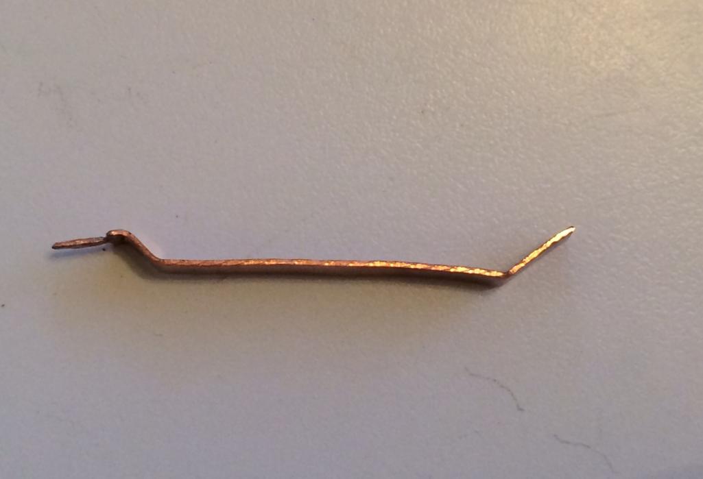
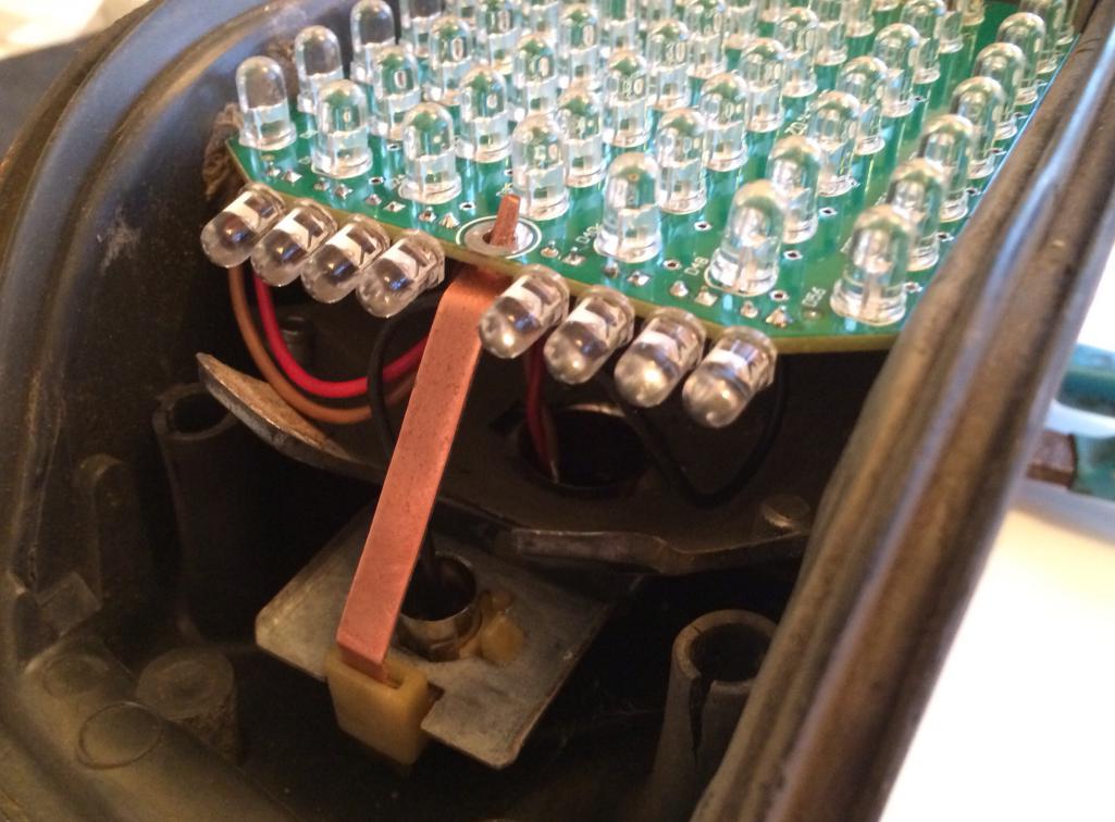
Posted by: ClayPerrine Apr 1 2014, 04:55 PM
I don't know if you thought of this, but will the stock turn signal flasher unit on a 914 receive enough current to run the flasher when you use LEDs in the turn signal units?
I know the early cars with two turn signal indicators were designed to flash the indicators once then dim them if you have a bulb out on that side. You may end up with the indicators not working if the LED boards don't provide enough load.
Just thinking......
Posted by: ClayPerrine Apr 1 2014, 04:57 PM
Another thought....
How about an LED setup to go inside the chrome strip on the back of the targa band for a third brake light? Just cut a slot and put in a clear lens and use red LEDs. It is right at eye level for most cars, and you could run it the width of the car. They are sure to see that brake light!
You build that one and I want to be the first in line to buy it!
Posted by: CptTripps Apr 1 2014, 06:42 PM
These should be the right voltage without modification. Spoke is pretty adept at that stuff. I believe his idea is to make direct replacements for the OEM locations...not invent new ones.
That being said, I'm going to be modifying my chrome strip to have about 6 red LEDs in it for a 3rd light.
Posted by: Cairo94507 Apr 1 2014, 07:16 PM
A high mount LED 3rd brake light is in my build sheet with Scotty. It will install in the chrome strip and I am hoping to find a suitable unit that is approximately 10-12" in length with a clear lens so it is basically invisible until illuminated. If anyone has any ideas or suggestions for a high quality unit please send me a message.
OK back to your regularly scheduled program
Posted by: Spoke Apr 1 2014, 07:17 PM
I believe I figured out a solution.
Using some old copper I had, I crafted a piece to go up from one of the clips, and into the hole on the board. This SHOULD do the trick.
Spoke: Before I power this up, is there an issue with this piece being grounded?
I like it! What is that plastic piece that secures the bottom of the clip? I saw those on my housing but didn't investigate.
The thin clip won't give much up and down stability but I think the PCB is pretty tight in the housing so there should be little up/down movement.
No worries about shorting out at the hole locations. As long as nothing touches the LED leads you'll be ok. Let me know how these look when you power them.
Posted by: Spoke Apr 1 2014, 07:21 PM
I don't know if you thought of this, but will the stock turn signal flasher unit on a 914 receive enough current to run the flasher when you use LEDs in the turn signal units?
I know the early cars with two turn signal indicators were designed to flash the indicators once then dim them if you have a bulb out on that side. You may end up with the indicators not working if the LED boards don't provide enough load.
Just thinking......
Good point. If the lighter load of the LED lights causes the flasher to stop then one will have to add a resistive load or change to an LED-compatible flasher.
Mine works fine with the LED lights but YMMV.
Posted by: Spoke Apr 1 2014, 07:33 PM
Another thought....
How about an LED setup to go inside the chrome strip on the back of the targa band for a third brake light? Just cut a slot and put in a clear lens and use red LEDs. It is right at eye level for most cars, and you could run it the width of the car. They are sure to see that brake light!
You build that one and I want to be the first in line to buy it!
I hope that someone comes up with a great solution for the 3rd brake light. The 914 really needs one of these.
This one isn't on my radar right now. As you point out, there's probably more mechanical modifications needed than electrical. There's all kinds of strip LEDs out there that would work well. The key to this one is to cut a slot in the chrome, put a clear lens on it and mount the LED strip behind it.
Posted by: 914Mike Aug 4 2014, 02:04 PM
Glad you got them lit up. I remembered that I didn't mention how to install the bulb bases in the sockets. They can be tricky. I've gotten so used to them cause I've installed and removed these a hundred times.
The trick is to put your finger in the socket like in the pic. This will give enough pressure and friction to install.
That works. A better way is to take a stiff wire, like a big paper clip and form it into a squared off U shape, then solder it to the insides of the bayonet tube to make a handle...
Posted by: 914Mike Aug 4 2014, 03:12 PM
I don't know if you thought of this, but will the stock turn signal flasher unit on a 914 receive enough current to run the flasher when you use LEDs in the turn signal units?
I know the early cars with two turn signal indicators were designed to flash the indicators once then dim them if you have a bulb out on that side. You may end up with the indicators not working if the LED boards don't provide enough load.
Just thinking......
Clay;
I've had to take an old 4-pin flasher apart to re-use the base. First you figure out which pins are what with the old one, then you look at one of the new LED types and match the pins. They will have +, -, and L for light marked on them. By stacking the old base under the new one you can solder the pins together and then jumper the right pin over to the extra dash light pin on your old base. I seem to remember it was the ground that got my dash lights working, but I could be off on that...
I think this is the one that works, all except for the dash light/s:
eBay item number:
330939693249
CF-13 GL-02
FYI, a CF-13 JL-02 is the same circuit with the + an - terminals switched. I got that one to work by taking the cover off and rewiring it to what I needed. They are about half of the $ compared to the one above right now...
Posted by: PThompson509 Aug 4 2014, 04:00 PM
Another thought....
How about an LED setup to go inside the chrome strip on the back of the targa band for a third brake light? Just cut a slot and put in a clear lens and use red LEDs. It is right at eye level for most cars, and you could run it the width of the car. They are sure to see that brake light!
You build that one and I want to be the first in line to buy it!
I hope that someone comes up with a great solution for the 3rd brake light. The 914 really needs one of these.
This one isn't on my radar right now. As you point out, there's probably more mechanical modifications needed than electrical. There's all kinds of strip LEDs out there that would work well. The key to this one is to cut a slot in the chrome, put a clear lens on it and mount the LED strip behind it.
I just added some pre-taped side-emitting LEDs under the chrome. The strip is water proof, and has stuck there for about 2 years now with no sign of failure.
http://www.superbrightleds.com/cat/side-emitting/filter/Color,Red,136,4639:Water_Resistance,Waterproof_%28IP67_and_above%29,135,4568:
Cheers! Peter
Powered by Invision Power Board (http://www.invisionboard.com)
© Invision Power Services (http://www.invisionpower.com)