Printable Version of Topic
Click here to view this topic in its original format
914World.com _ 914World Garage _ LS1 Conversion
Posted by: andys Feb 21 2013, 12:43 PM
Here's the start of a retrospective build thread of my LS1 conversion. It took a few years to get it done mostly due to not wanting to be a slave to the project, and work on it for the enjoyment; and of course when family obligations allowed......teen daughter and high maintenance wife 
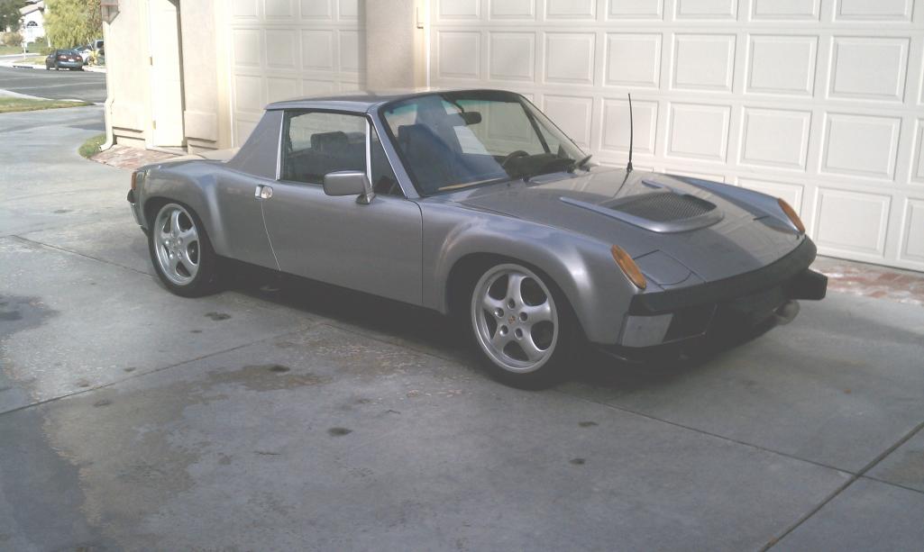
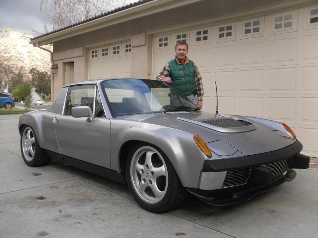
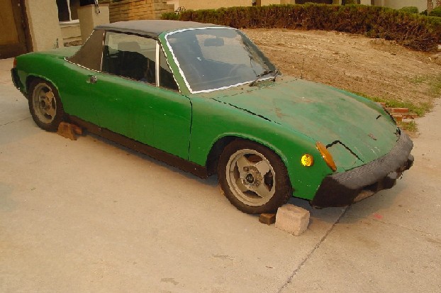
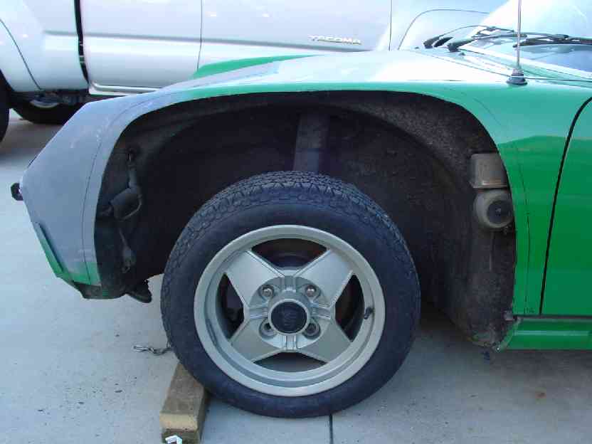
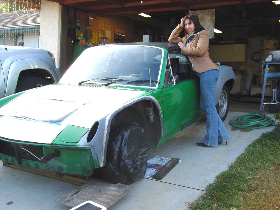
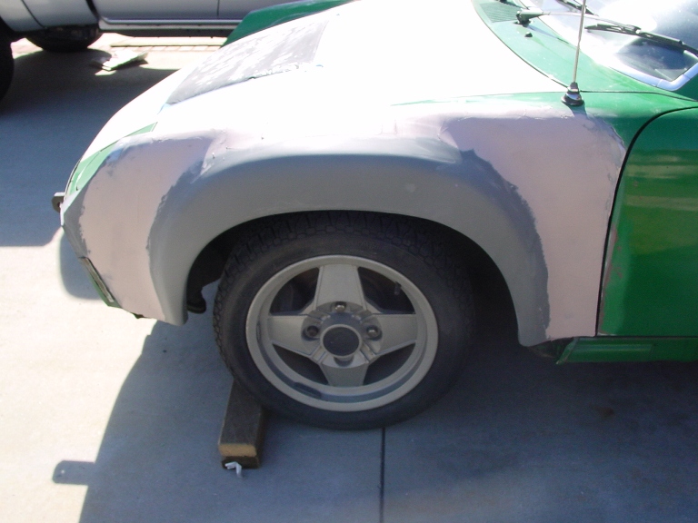
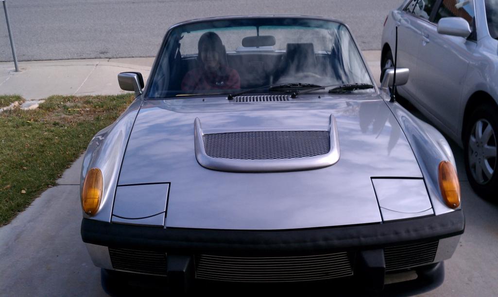
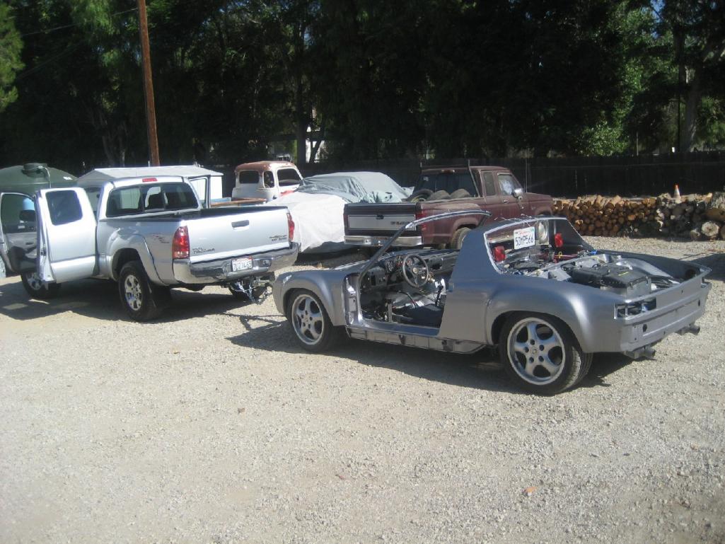
What I started with was a local orignal owner '75 2.0 with 139K miles. The original owner "drove the heck out of it" until something died in the electrical system and he parked it in the garage for 14 years, as evidenced by the renewal tags. Only body damage was when he submarined the rear of a Mustang and creased the hood and flattened the left signal light pod. Otherwise, it was a good condition rust free (SoCal) car.
Brief specs are: '01 LS1 Z28 motor, Audi 01E 6 speed tranaxle, 911 front suspension, custom made rear trailing arms, Koni shocks, 993 wheels, and AC.
Below, are photos of what I started with, and what I ended-up with. I'll do my best to re-trace the build process, so if you have any questions along the way, please ask.
BTW, how does one place text between photos in the same post?
Andys
Attached thumbnail(s)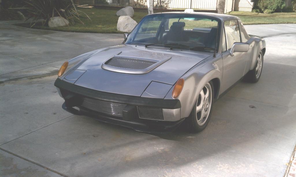

Attached image(s)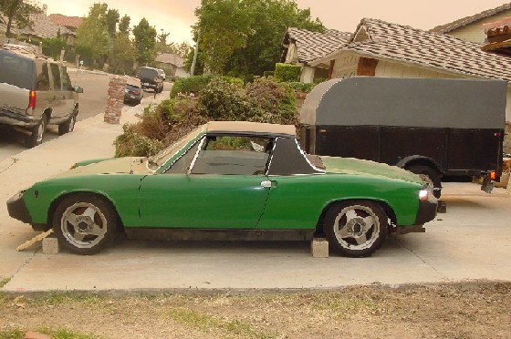
Posted by: Tom_T Feb 21 2013, 12:55 PM
In Full Edit mode - just add space lines with your enter/return key & type in there.
IMHO the pix look better with a line space between them anyway, especially when large.
Posted by: andys Feb 21 2013, 01:11 PM
I decided quite quickly, that I wanted to go with a modern V8 motor with all the EFI controls, so I went with an all aluminum LS1. Before acquiring the motor, I went through the somewhat difficult process of selecting the kind of transaxle that would be rugged enough, reasonable in cost, decent gearing, all in a modern package. I really liked what the Audi 01E transaxle offered, but there were two problems. 1.) The FWD version was never available in the US, and 2.) no one made an adapter plate (at the time) to mate to a LS1. Being the engineering type with a background in managing prototype machining, I could make the adapter plate myself. So now I'm relegated to find said 01E. My search took me to Europe, and after a number of inquiries, I found a low mileage (12K kilometer) 01E from an '02 Passat TDI, which has the more desireable gearing of the 01E series. After a few phone calls and arranging a freight forwarder, it arrives at my door in exactly one week! Price? $1100 landed, though this was some years ago when the exchange rate was way more favorable than it is today. Needless to say, I got a killer deal that's likely to never be duplicated again.
Andys
Attached thumbnail(s)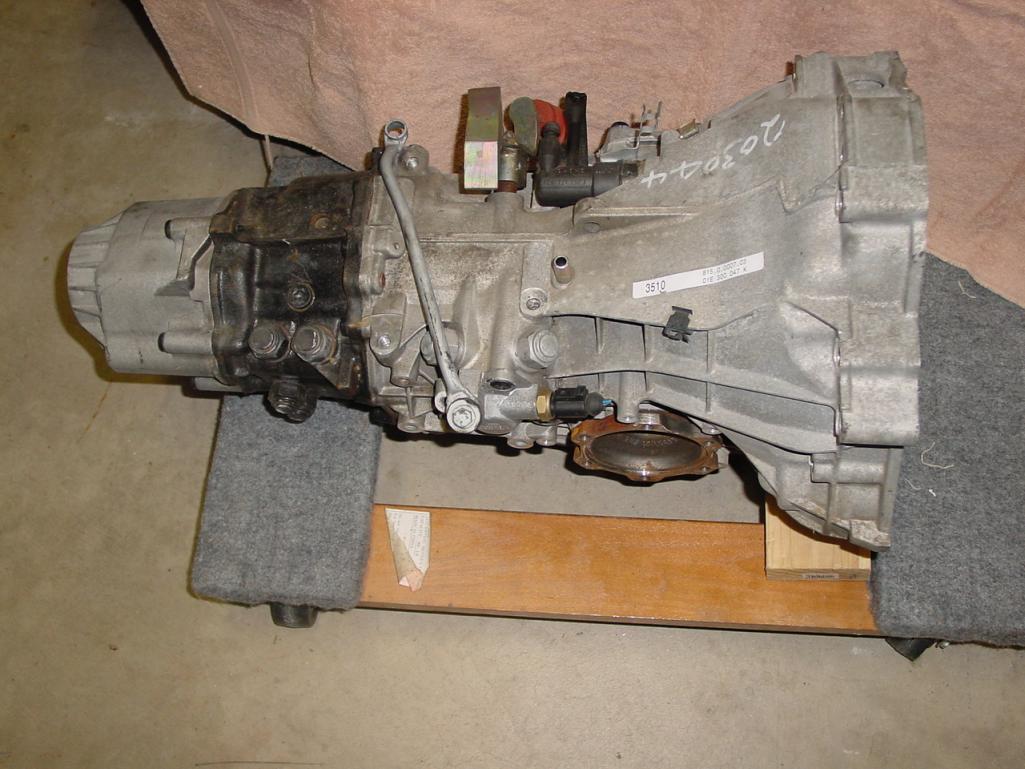
Attached image(s)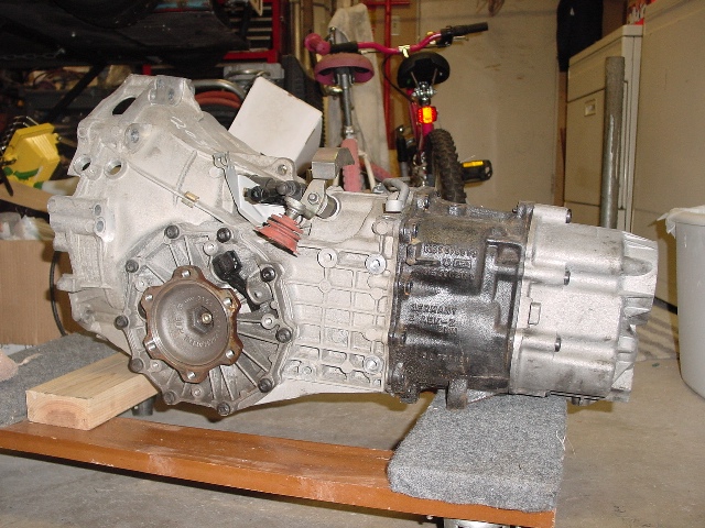
Posted by: andys Feb 21 2013, 01:16 PM

In Full Edit mode - just add space lines with your enter/return key & type in there.
IMHO the pix look better with a line space between them anyway, especially when large.
Tom,
What do you mean "in full edit mode?" Is this done while I'm in the New Post/Add Reply window? Where would I find that button/tab/selection?
Thanks,
Andys
Posted by: worn Feb 21 2013, 02:07 PM
In Full Edit mode - just add space lines with your enter/return key & type in there.
IMHO the pix look better with a line space between them anyway, especially when large.
Tom,
What do you mean "in full edit mode?" Is this done while I'm in the New Post/Add Reply window? Where would I find that button/tab/selection?
Thanks,
Andys
Andys,
It doesn't matter, keep the photos coming! I love the story so far.
Posted by: andys Feb 21 2013, 02:34 PM
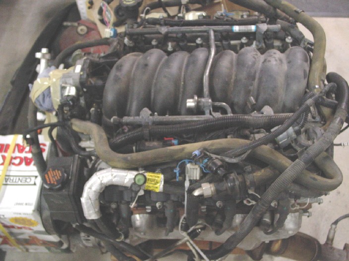
I wanted to avoid having a motor shipped, so I started searching for local yards that may have a LS1 with reasonably low mileage. What I found, was a salvage yard that specializes only in late model Camaro's/Firebird's, but motors go fast so I had to stay on top of them with frequent phone calls. They get two cars in, so I run down there right away. There's a '02 Firebird with 30 some K miles, and had the late and more desirable LS6 heads, but I found a mount for a nitrous bottle in the truck, so I passed. The other car was a "01 Z28 with 49K miles. Looked well kept and was hit in the rear. Started immediately, so I closed the deal. I had to come back the next day so they could pull the motor. Turned out that when I got there, they hadn't even started, so I waited another 1 1/2 hrs before they were ready to load it into my truck. Motor came complete with all the systems (harness, PCM, manifolds, cats, flex plate, starter, even the Camaro air intake box).
Andys
Attached image(s)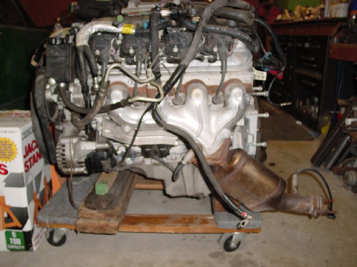
Posted by: andys Feb 21 2013, 05:48 PM
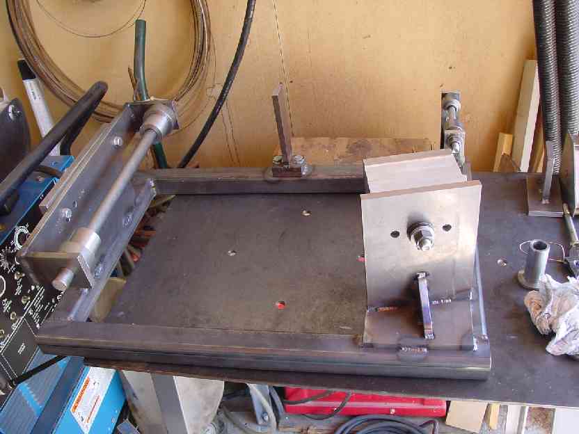
I wanted to start by adapting the motor to the transaxle, which would allow me to do all my trial fitting of the assembly into the chassis. So, adapter plate, flywheel here we come!
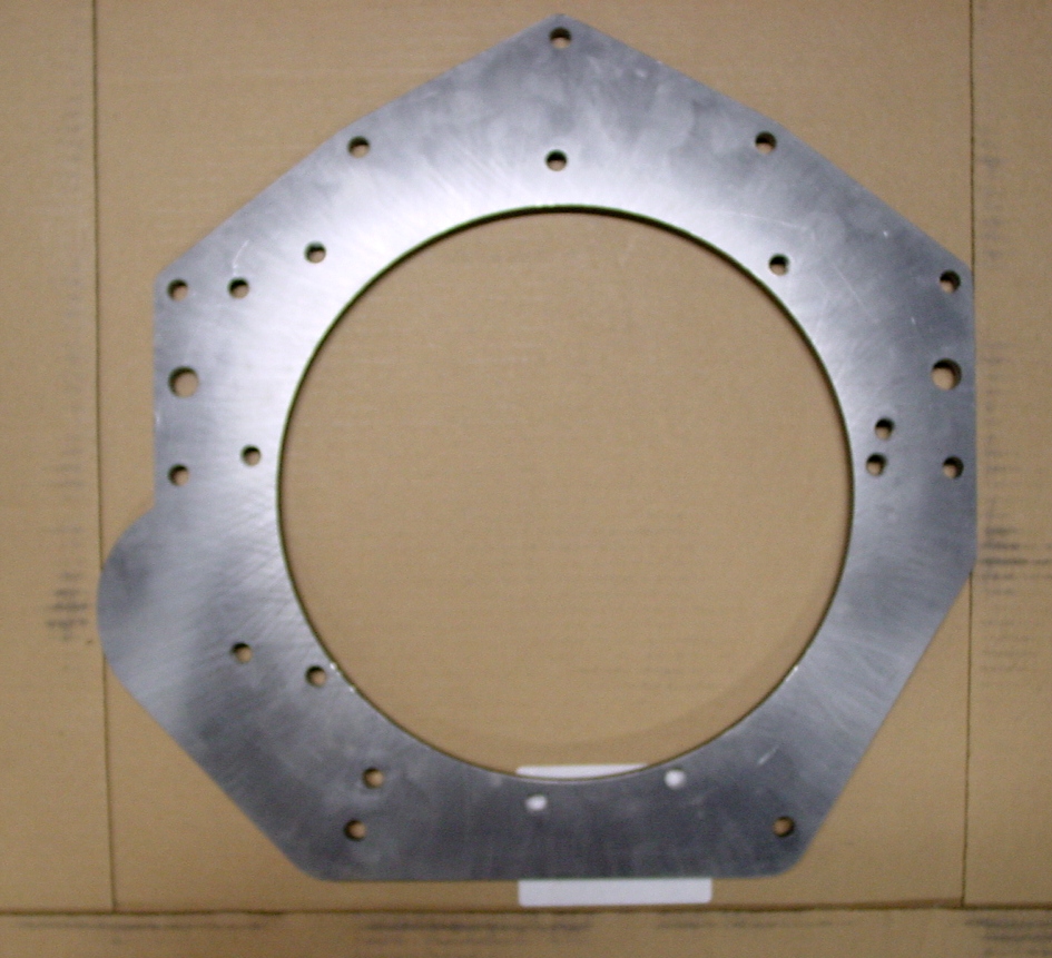
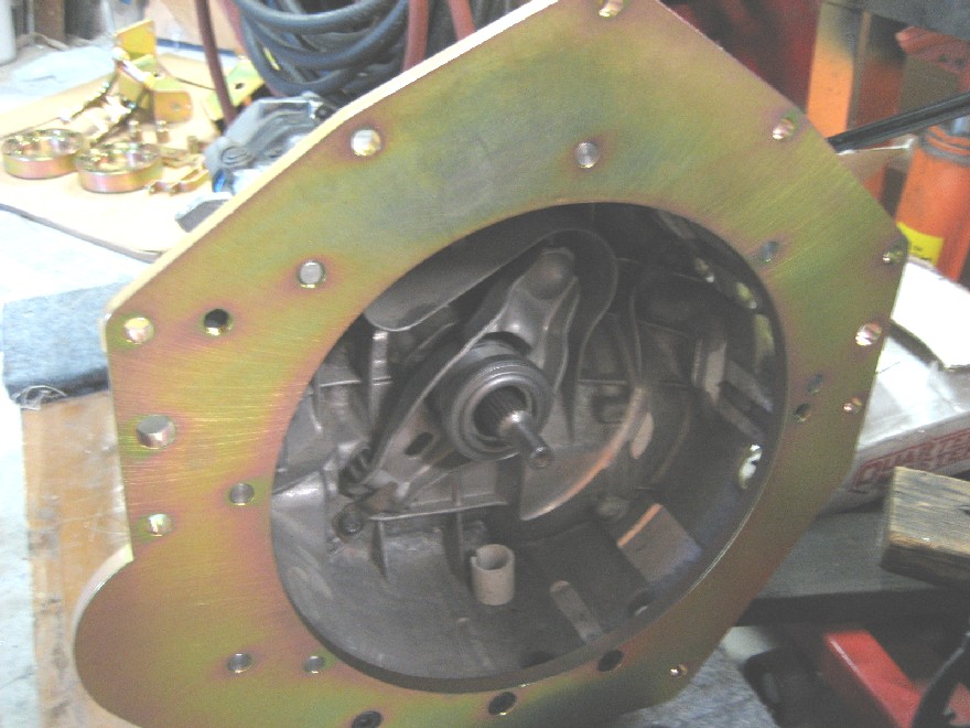
I layed-out the transaxle bolt pattern using a surface plate and height gage with indicator. Did 'x', then rotated the transaxle 90 degrees, and did 'y' coordinants both about the center of the input shaft. The LS1 side was simple, since it has the same bolt pattern as a Gen I SBC, minus one of the holes. There are two bolt positions on the oil pan that some people don't use, but I chose to use since the oil pan is deemed a structural component. From this information, I made a master plate of 1/4" aluminum cast tooling plate (for its stability) to check the alignment.
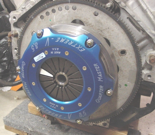
Making the adapter plate is only part of the story, as you need to resolve the starter, flywheel, clutch disc, pressure plate, and TO bearing interfaces. Again, no one at the time made anything for the LS1, so I started from ground zero. After much research, I finally hooked up with QuarterMaster as they were so willing to field all my questions, and of course being race guys, they understood what I needed to get everything to fit up. Let me take a moment to gush at how great they were to deal with, typical Mid-Western stock car race guys that were very accomodating to all my needs; second to none in my book!
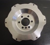
So after all the planning and designing, I started in on the fab work. I started with a 3/4" thick hot rolled steel plate and had the profile water jet cut, which I then sent out to get blanchard ground on both sides down to 1/2". I then drilled and tapped the necessary hole pattern on my mill. Final yellow zinc plating. To get the correct axial spacing, an additional 1" of thickness was required to clear the flex plate and accommodate the starter. I water jet cut a piece of 1" cast aluminum tooling plate as a spacer. I also made alignment dowel extenders to span that distance.
For the flwheel/clutch, I went with the QuarterMaster 8 1/4" button flywheel and bronze/ceramic clutch disc. The pressure plate diaphram spring that was recommended make this combo good for 450 ft-lbs. QuarterMaster does make a button flywheel with the LS1 crank bolt pattern, so no adapters were necessary. I did have to make a 1.1" thick spacer plate to move the whole clutch assembly to locate properly on the transaxle input shaft. I used a QuarterMaster spherical faced TO bearing which I adapter to the existing TO bearing carrier on the transaxle. This way, I could retain the stock TO fork and hydraulic slave cylinder.
That was long-winded....here are some photos:
Attached image(s)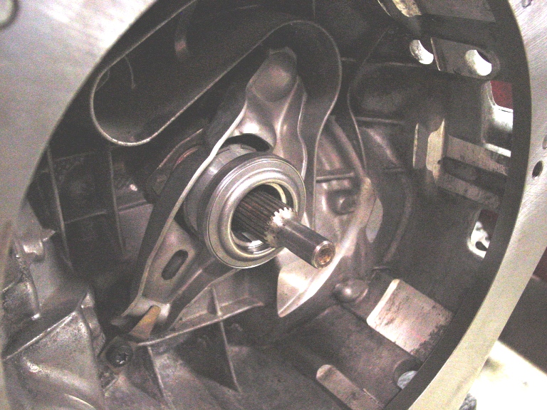
Posted by: Bruce Hinds Feb 21 2013, 06:33 PM
Tell us about that jack!
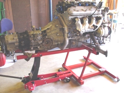
Posted by: andys Feb 21 2013, 06:47 PM
Tell us about that jack!
Bruce,
I spend 6 years on the car, and you ask about the jack..........
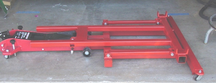
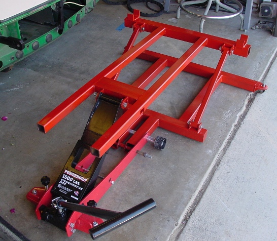
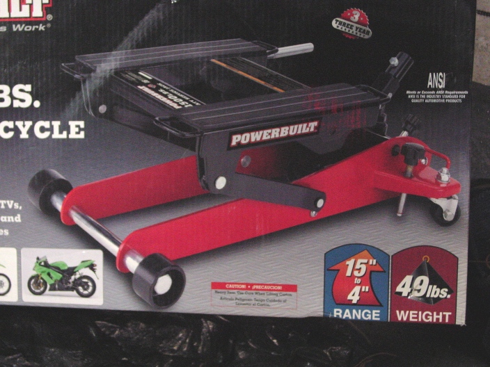
Made trom an ATV jack, it colllapses down to 4". That allows me to get the motor under the car without having to raise it up so high. Handles the LS1 and trans just fine.
Attached image(s)
Posted by: turk22 Feb 21 2013, 07:25 PM
Lovin this story and the work you did.
Looking forward to hearing the rest of it..

Posted by: Bruce Hinds Feb 21 2013, 07:47 PM
ask about the jack!
Well yeah... the cars freak'n gorgeous and the trans setup is sweet. But that jack, that's a great piece of work.
Well done! On all accounts.
Did you make the hood vent, or is that from something else?
Posted by: kg6dxn Feb 21 2013, 07:47 PM
Keep going! We need more!
I know you did custom axle flange work but I will through out that Boxster output flanges (100mm) snap right in. I was going to go your route but the factory Porsche (Audi) part fits so well.
Posted by: andys Feb 22 2013, 10:27 AM
ask about the jack!
Well yeah... the cars freak'n gorgeous and the trans setup is sweet. But that jack, that's a great piece of work.
Well done! On all accounts.
Did you make the hood vent, or is that from something else?
Bruce,
Yeah, I used the heck out of the jack; glad I took the time to fab it up.
The hood vent is a creation that was designed by an Art Center College of Design student, since I have zero artistic/creative skill. Modeled it out of foam, then covered in f'glass.
Andys
Posted by: andys Feb 22 2013, 12:32 PM
With the motor and transaxle coupled together, I now set about the task of fitting it to the car.
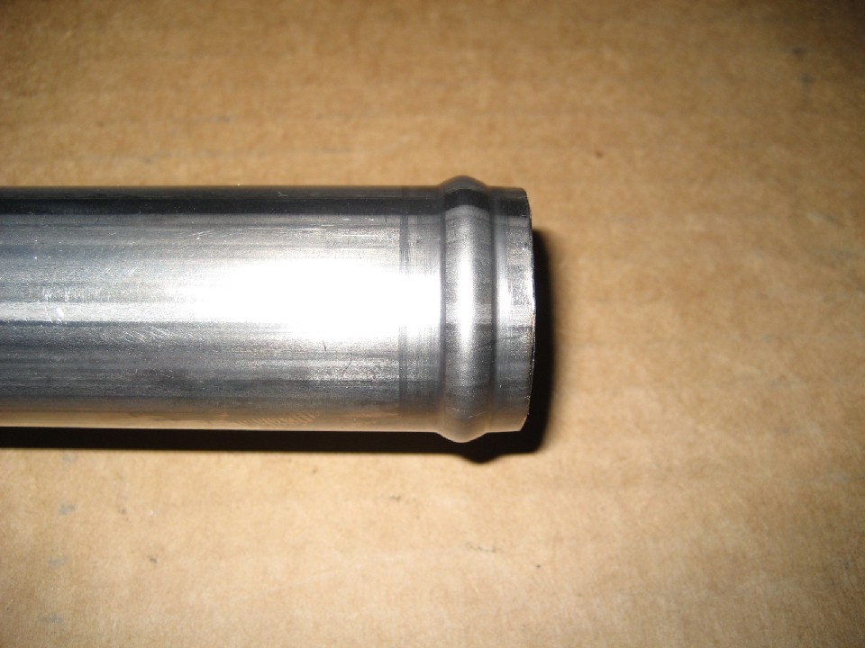
Initial fittng revealed that the motor damned near fits with the water pump in place, which means it still doesn't fit. After some measuring, I determined that if I use the LS2 water pump with the short pulley, I'll reduce the length by about 2" (from memory, which is not that great anymore). Found a brand new LS2 water pump on Ebay along with a LS6 Vette crank pulley (which is also shorted than the LS1 by some 3/4") to line up with the water pump. Fitting again revealed that I would only need to move the firewall hump into the cabin 1 1/8" to get everything to clear......well almost. The water pump outlet points straight forward into the firewall, so I needed to re-think that. Some of you may think why should I goof with the stock water pump, when a remote mechanical or electric water pump (Meziere) might offer an easier solution? Well, frankly I like stock components over aftermarket as they are properly engineered and designed for dependability. Another issue that led to my decision, was the need for a properly configured thermostat, and heater hose and valving. To resolve the water pump outlet, I capped the original outlet, drilled a hole pointing toward the passenger side, machined a new neck with barb for a 1 1/4" hose, and TIG welded it in place. I did a similar thing with the inlet side; I machined a neck with barb, and TIG welded it to the stock thermostat housing in a more favorable position.
Attached thumbnail(s)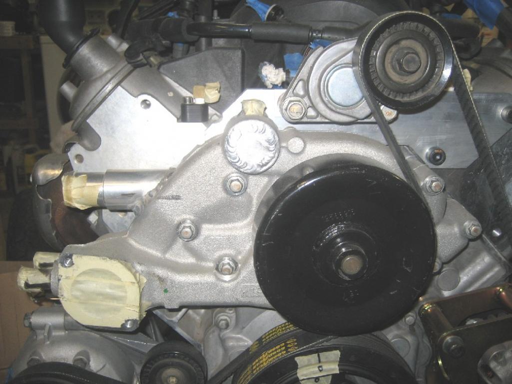
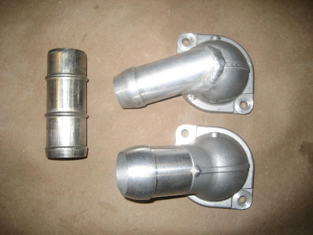

Attached image(s)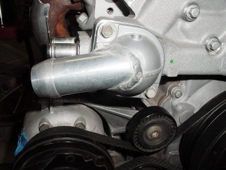
Posted by: TurboWalt Feb 22 2013, 02:15 PM
Great work, keep the pics coming!
Posted by: BIGKAT_83 Feb 22 2013, 02:29 PM
Great work! keep the pictures coming. I keep coming back to the site every 10 mins.
Bob
Posted by: andys Feb 22 2013, 03:07 PM
While not exactly in the correct sequence of the build, I will probably group things so as to keep some sense to the project. While waiting for one thing, I would switch over to say the flare installation or chassis stiffening in between, but anyone that's done this kind of thing before, knows what I'm talking about.
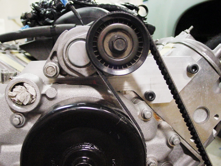
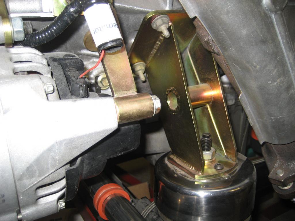
Let's proceed to the accessoy drive on the front of the motor. The water pump pulley and the crank pulley are in alignment, but the AC part of the crank pulley is now about 1" closer to the block than the LS1 AC compressor pulley, so I had to fab a plate that moves it back,,,,,but not so fast. The compressor now interfers with the header (stock cast iron LS6 header), so I remake the plate to also moving the compressor down by 3/4"....but now the compressor interfers with the cool looking Vette aluminum motor mounts I got from Ebay. After some thought, I decide to fab my own motor mounts. Ok, back to the accessory drive. The alternator (in it's stock position) needs to move closer to the block as well, so I found it easier to fab my own alternator mount; done deal. Now, the serpentine drive needs to be configured. What I came up with was to mount the tensioner high and somewhat centered, which coincidentally turns out to be the same solution that Factory Five uses on their GTM cars (their bracket is steel, mine is aluminum). I measured the necessary belt length with a string, then searched the Goodyear site and found what I needed.
Not as many photos as I'd like to display, but that's all I have. The zinc plated part is the alternator front mount (there's also a rear mount).
Attached image(s)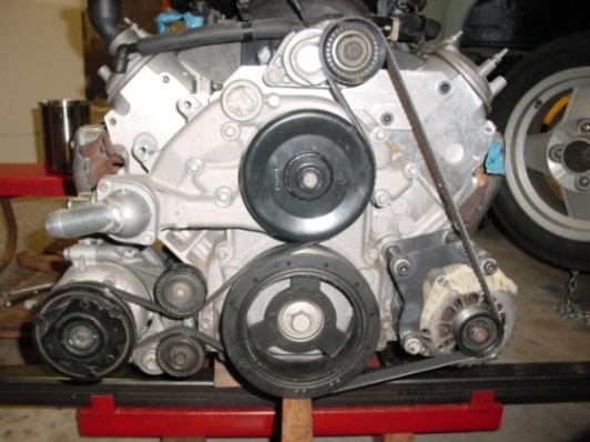
Posted by: worn Feb 22 2013, 09:52 PM
Amazing. Inspiring. I wanna drive it!
Posted by: rick 918-S Feb 23 2013, 07:39 AM


Posted by: Cairo94507 Feb 23 2013, 08:03 AM
I am in awe. Amazing skills and work. Keep 'em coming.
Posted by: jersey914 Feb 23 2013, 08:54 AM
Cool conversion, way out of my league
Posted by: Bruce Hinds Feb 24 2013, 10:16 AM
Holy smokes, you're a handy guy to have around the shop. Makes my work look shameful.
Posted by: andys Feb 24 2013, 12:01 PM
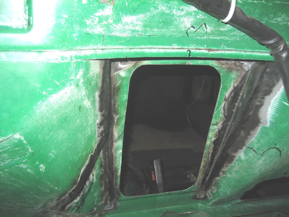
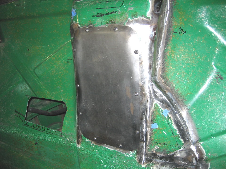
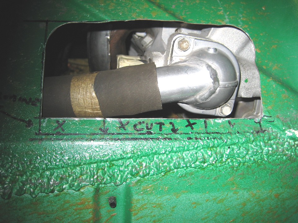
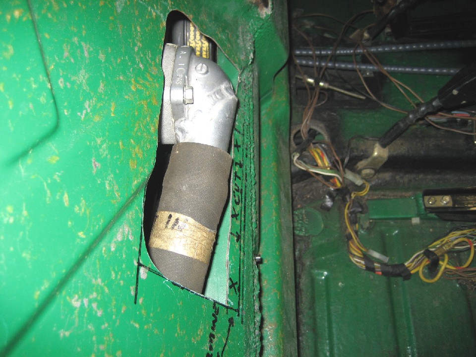
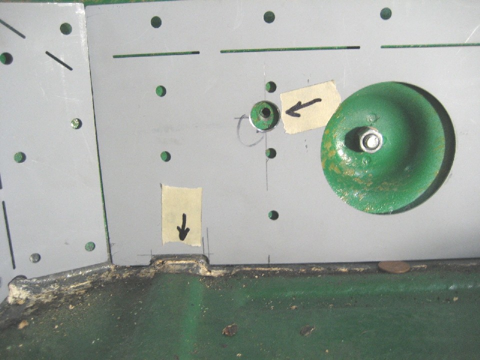
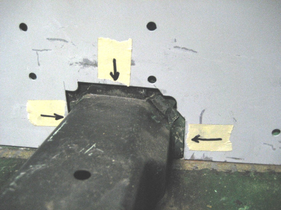
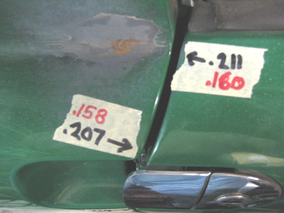
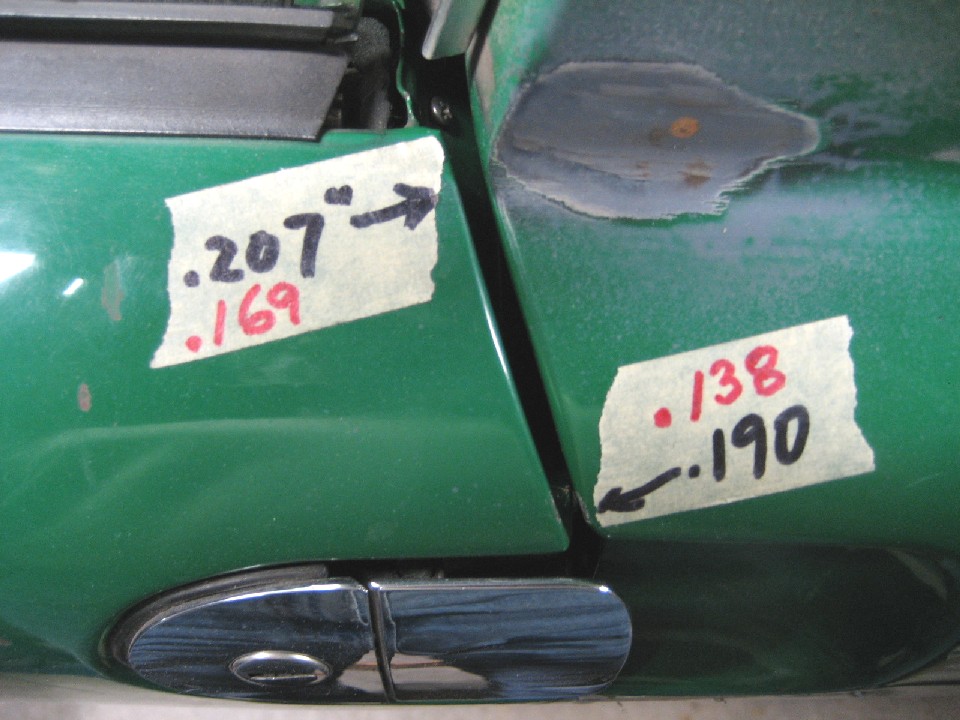
I mentioned earlier the need to move the firewall hump by 1 1/8" to get the water pump and accessory drive to clear. I wasn't sure how I'd deal with the intrusion into the cabin, but it seemed to be something I could tackle later in the build....I actually don't like proceeding without figuring everything out in advance (typical engineer!), but I though it was low risk.
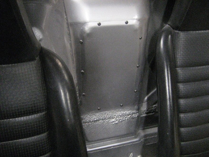
The firewall hump only needed to be moved forward at the top. The crank pulley and alternator clearance at the bottom was adequate as is. What I did, was to cut the outline of what I needed, but not cut the bottom. I simply cut and inverted 'U', (attached at the bottom) and bent the it forward at the top. I made filler sections, and welded them in. Also, as all us 914 types do, an access panel was fabricated. Notice too, I had to make a sort of pie cut portion on the drivers side of the hump to clear the accessory drive serpentine belt.
One additional area that required clearance, was the thermostat housing. The firewall needed a small hump there too, so I decided to make a removable hump thingy. I don't have a photo of the removable hump, so I'll describe it briefly. I only needed about 3/4" worth of hump, so I took a sheet metal pan I found at McMaster-Carr that was about 4" x 8" x 2" deep and cut it to 3/4" and welded a flange around its perifery. Not as easy as it sounds, since if you notice in the photos, there are stiffening ribs in the firewall which required the flange to change planes, so it was a bit involved. As with the access panel, I made this hump thing removable as well. To get the motor out of the car, the thermostat housing needs to be removed beforehand....things are that tight!
Photos are out of order, and some show the result in its final painted form, but you get the idea.
Attached thumbnail(s)
Attached image(s)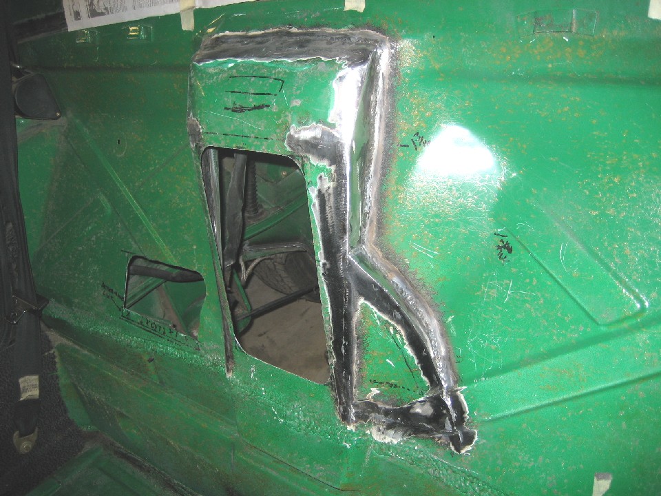
Posted by: messix Feb 24 2013, 12:14 PM
have you left the tranny in the original location or have you moved it back a bit as in most v8 conversions? [half shafts canted back wards toward the tranny flanges]
Posted by: andys Feb 24 2013, 12:16 PM
have you left the tranny in the original location or have you moved it back a bit as in most v8 conversions? [half shafts canted back wards toward the tranny flanges]
I'll get to that in the next post or two.....stay tuned!
Andys
Posted by: messix Feb 24 2013, 12:24 PM
have you left the tranny in the original location or have you moved it back a bit as in most v8 conversions? [half shafts canted back wards toward the tranny flanges]
I'll get to that in the next post or two.....stay tuned!
Andys
10/4 just wondering why all the effort on the front side and firewall and if it was necessary.... i know stupid question....

Posted by: andys Feb 24 2013, 05:32 PM
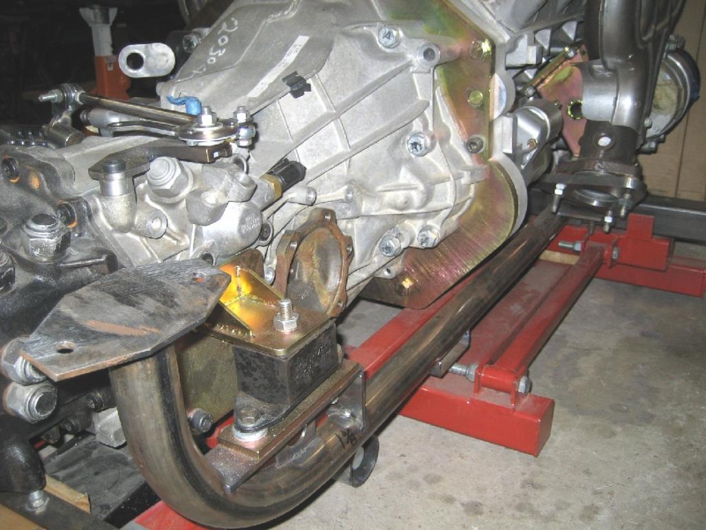
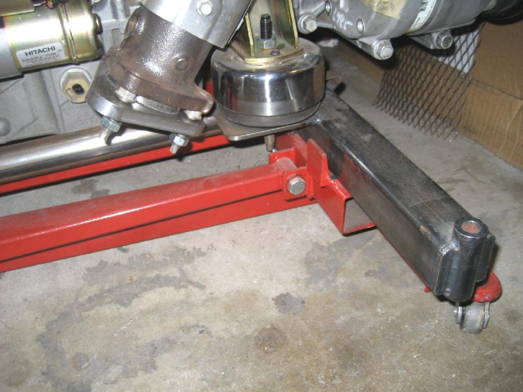
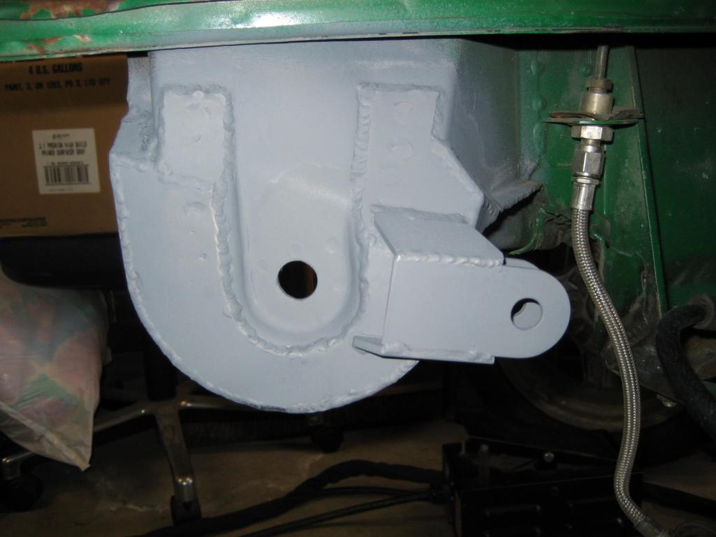
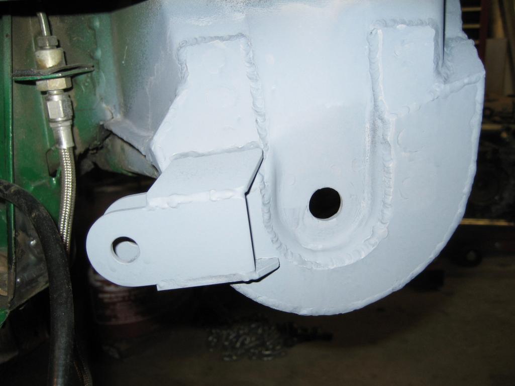
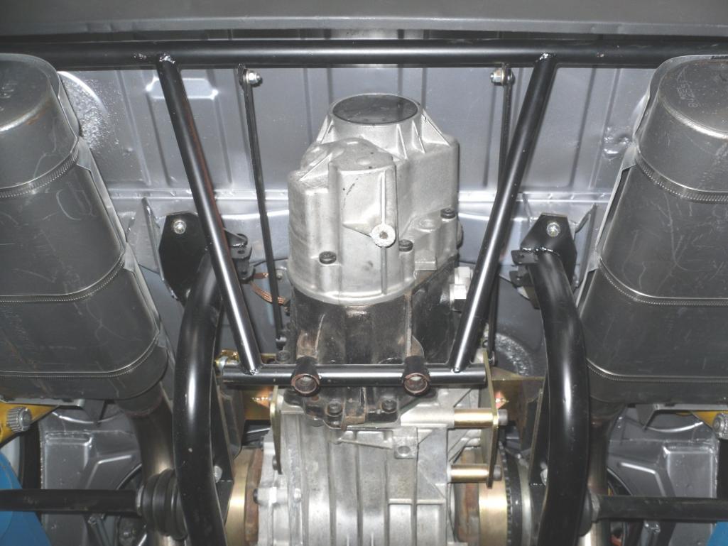
Determining where the engine/transaxle assembly would best be located was driven by a couple of things. The motor has to fit in the hole (engine bay), and the transaxle drive flanges need to line up both front to back, and height wise to the wheel hubs at ride height. I was fortunate in that the 01E transaxle is shorter by 1" from the drive flange axis to the bellhousing than the 901. After adding in the adapter plate thickness stackup, I basically ended up with the drive flange axis very close to the original front to back location, and about 3/4" lower (the axles are angled slightly upward to meet the wheel hubs). I couldn't get the motor/transaxle any higher in the chassis, as the bellhousing would run into the trunk floor at a point where I prefered not to cut it due to structural concerns. The amount of axle angularity was acceptable to me.
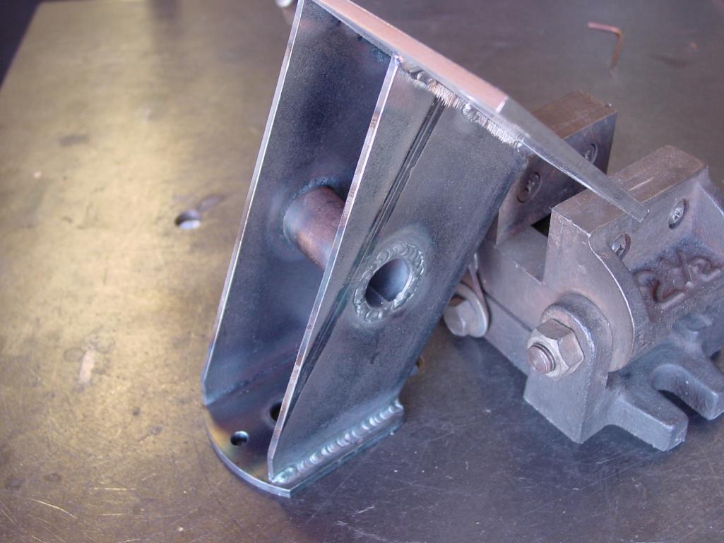
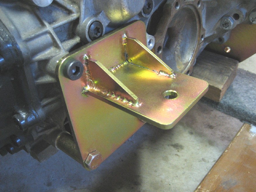
With that info at hand, I set about designing the mounting scheme. What I decided on, was a cradle arrangement that would allow me to R&R the engine transaxle as a unit. You'll notice in the photo where the engine/transaxle is on the jack, that I fabricated a temporary engine mount bar so that I could experiment with the exact location. First, I had to fab a set of motor mount pedestals, since those neat aluminum Vette motor ones interfered with the AC compressor, as mentioned earlier. I decided on using the stock Vette hydro-elastic mounts. Being close to the header flanges, I decided to make some heat shields to guard against damage. I found some stainless cannisters at WalMart, cut them down, drilled holes, and welded in some re-inforcement; turned out kinda blingy. For the rear transaxle mounts, I fabbed up some trans mounts, and I used some Chevy Caprice transmission mounts.
Where the rear cradle bolts to the 914 chassis, I did a little re-inforcement around the chassis mounts just in case....they looked a bit whimpy to me. So the whole cradle stays bolted to the motor/transaxle assembly and mounts to the 914 chassis in the stock locations (6 bolts).
Attached thumbnail(s)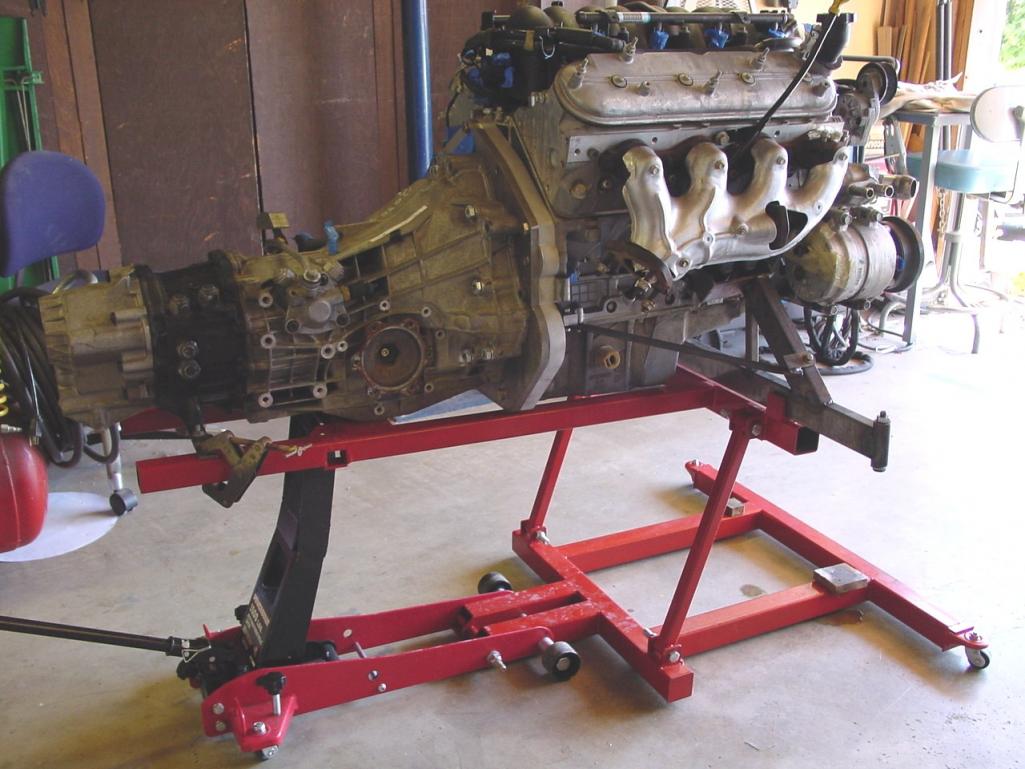
Attached image(s)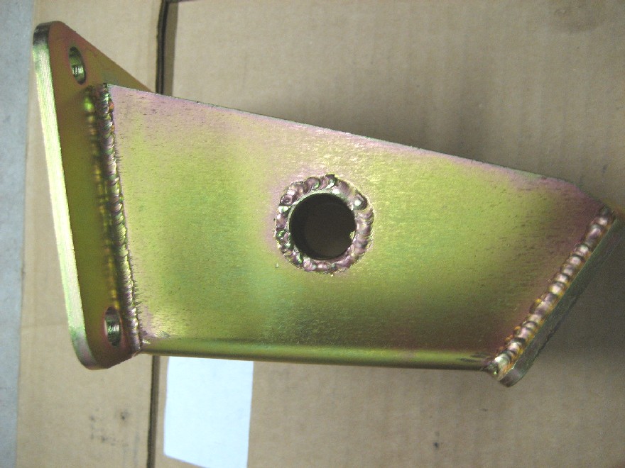
Posted by: Krieger Feb 24 2013, 07:16 PM
I like your work! Weight wise you better off with that mass forward. This car will scoot when your done.
Posted by: andys Feb 26 2013, 03:30 PM
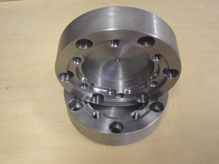
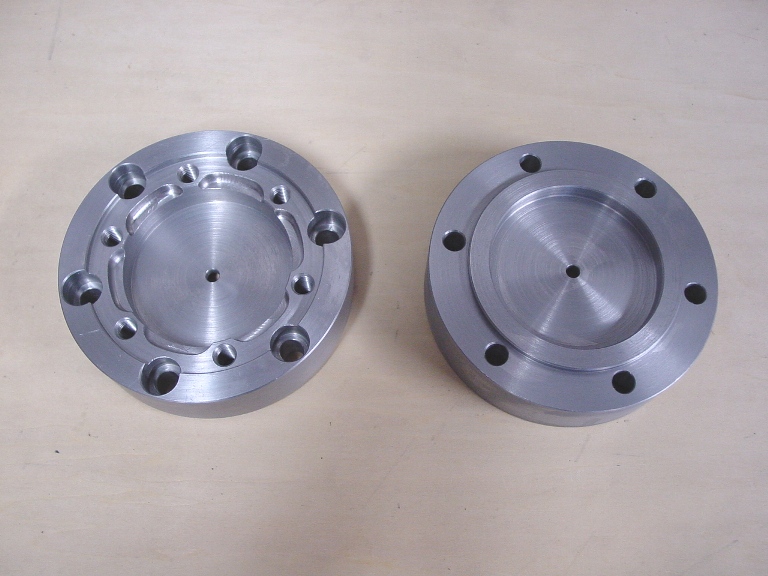
The 01E transaxle flanges are a tripoid design which requires adapters to couple to the 911 axles/CV's I intended to use. However, Audi does make an output flange that is the same pattern as the 911 CV; not sure what car/application uses those, but they are available. So why didn't I simply use those instead? Well, it's kind of a convoluted path I took, but perhaps you'll follow my logic(?). Let's see if you can follow this: The 01E output flanges are not symmetrical about the centerline of the transaxle.The centerline offset is 3/4", so one adapter would have to be 1 1/2" thicker than the other. For the axle length to work out properly, the short side adapeter just wouldn't work out (it would if I used the aforementioned compatible output flanges, but there's more). I liked the idea of using the larger 911 wheel bearing, but that won't fit the stock 914 trailing arm......and I wanted to use the 911 rear brakes too, so I decided to make a custom set of trailing arms which would allow me to place the bearing where it wouls accomodate the 911 axle length. More on the trailing arms later.
Anyway, this post is about the transaxle flange adapters and how I resolved that issue. So, to keep axle lengths equal, and hub bearing locations in a favorable location, I decided to offset the motor/transaxle assembly by 3/4" toward the passenger side. So I set about machining adapters that are equal in thickness, and would accept the 911 CV. They would receive a final zinc plating.
Andys
Attached thumbnail(s)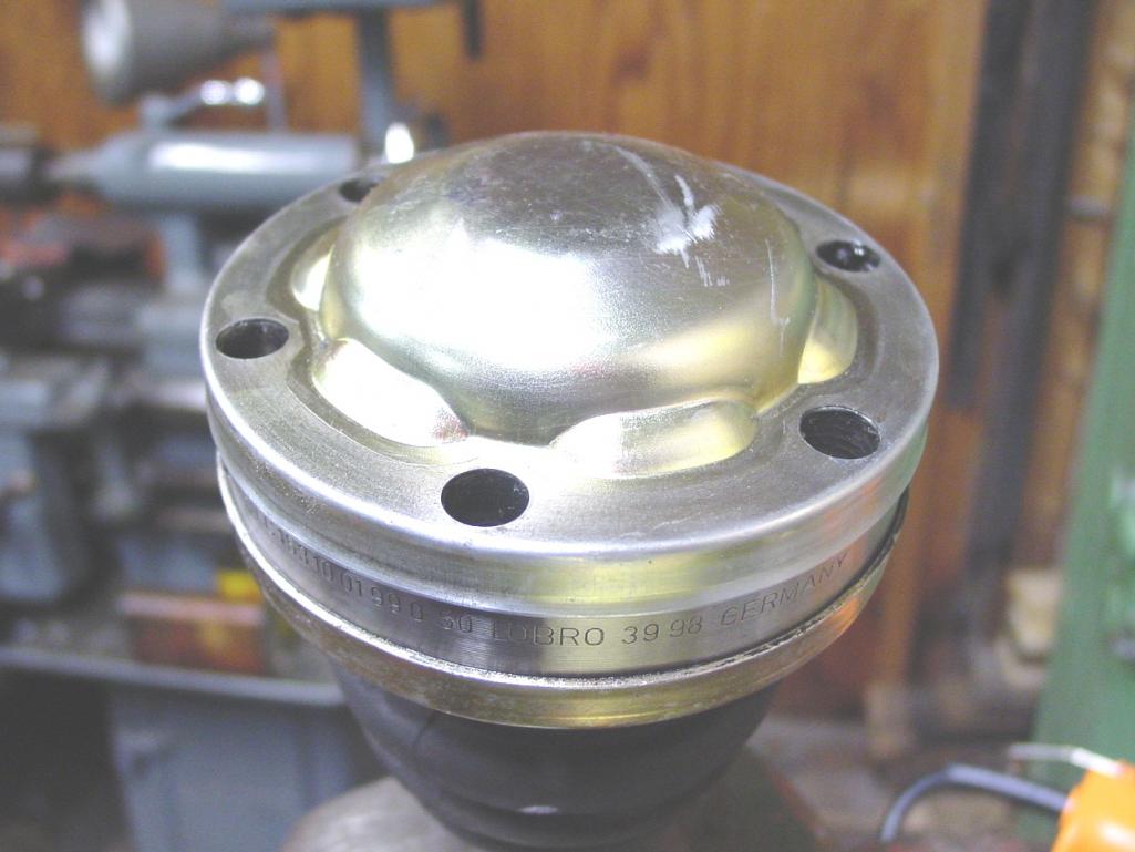
Attached image(s)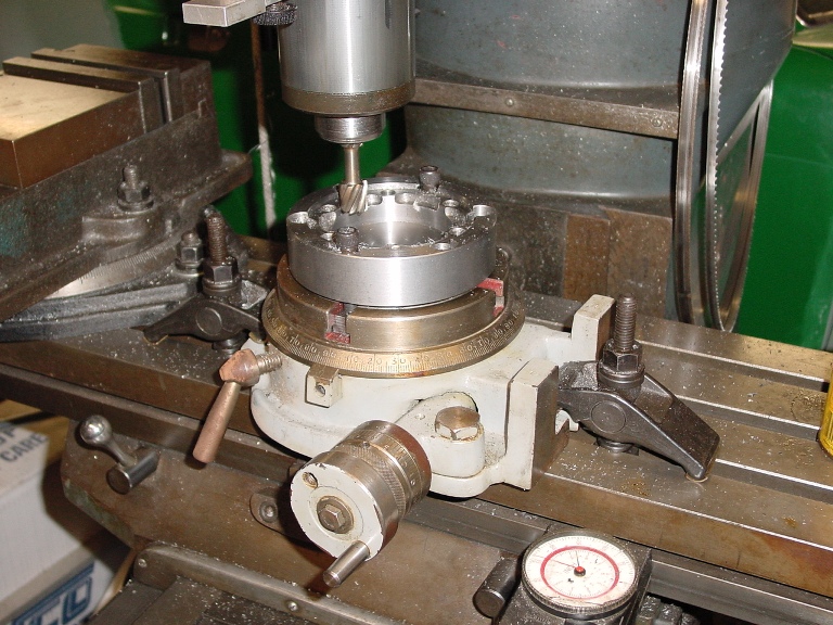
Posted by: charliew Feb 26 2013, 05:26 PM
great work. I also like the jack. I missed the part about the input shaft bearing. Is it the same size as the chevy? Or does the new flywheel have the appropriate bearing?
Posted by: andys Feb 26 2013, 06:34 PM
great work. I also like the jack. I missed the part about the input shaft bearing. Is it the same size as the chevy? Or does the new flywheel have the appropriate bearing?
I think you're asking about the pilot bearing. I had to machine and adapter that press fit into the Chevy crank, and I press fit an Audi pilot needle bearing into that. The adapter had to move the pilot bearing towards the transaxle in order to engage the input shaft. What I have seen with the designs since then, is where they mount the pilot bearing in an extension that's part of a custom flywheel.
Andys
Posted by: andys Feb 27 2013, 06:35 PM
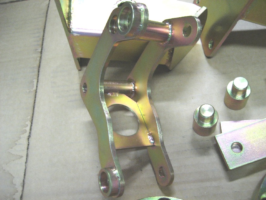
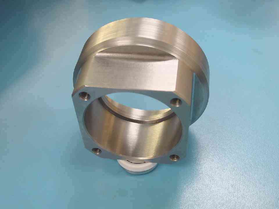
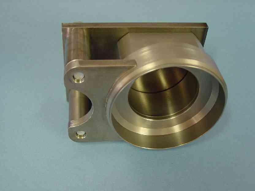
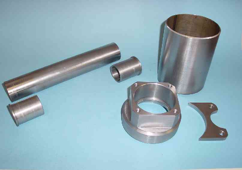
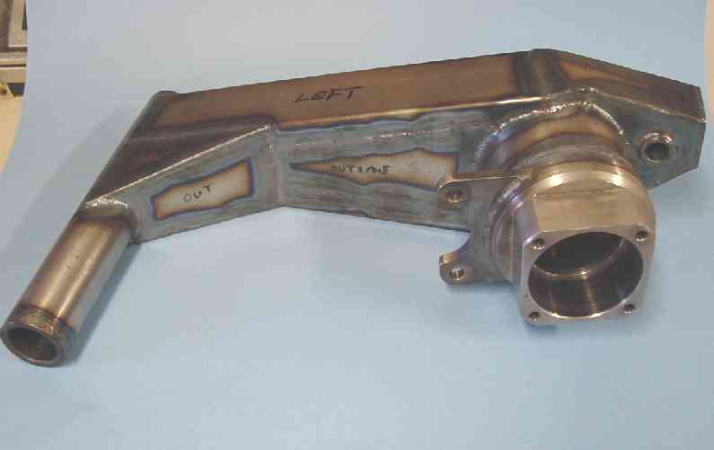
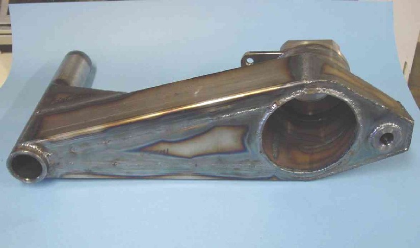
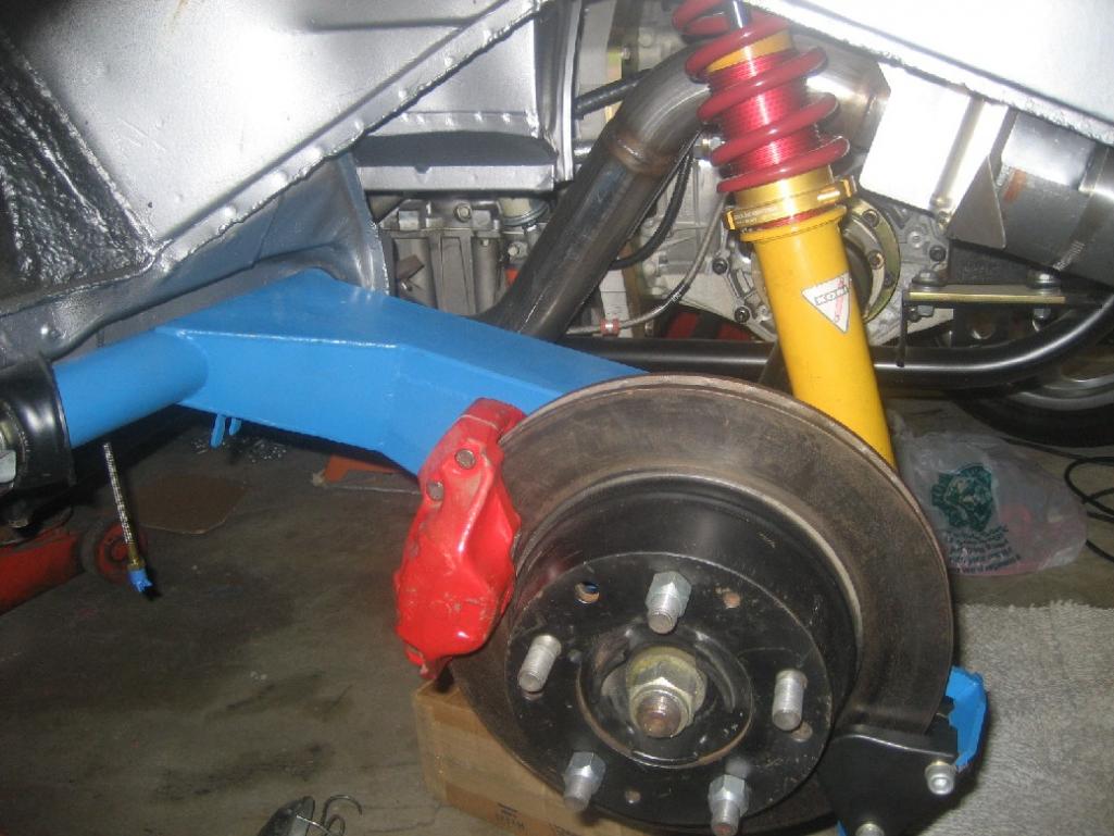
So we've got the motor/transaxle mounted, and the CV adapters made, how about we move on to making some custom trailing arms. The idea here, is to accomodate the larger 911 hub bearing (and 911 5 lug hub), and since the 911 axles combined with the 01E transaxle place the hub bearing farther outboard by 1.1", I can configure the trailing arm accoringly.
I first started by designing and fabricating a fixture that places everything at the proper relationships to each other. The fixture can make trailing arm geometry with zero, 1 1/2 and 3 degrees of camber relative to the pivot shaft. The stock angle in 1 1/2 degrees. Additionally, I can change the height of the (lower) shock mount to accomodate a lowered car. I chose to stay with the 1 1/2 degrees of camber, and the stock shock mount position (though in retrospect, I should have chosen a lower position). Oh, one other variable the fixture can accomodate, is the bearing carrier position. It can move inboard or outboard....as mentioned, I needed to move it outboard by 1.1" for my setup.
First on the list, was to machine the bearing carrier. That was a lot of work mostly due to all the hogging of steel when starting with a solid piece of round bar, but it got done! Then on to machining the other various components including the 911 caliper mount, the handbrake caliper mount, and so on. The pivot shaft housing (tube) is designed to accept Delrin bushings.
Once all the pieces were fabricated and placed in the fixture, I started TIG welding. Dang, that was a lot of work!
Hopefully, the photos will go a long way towards explaining haow it all got done, cause I don't type so fast!
Attached image(s)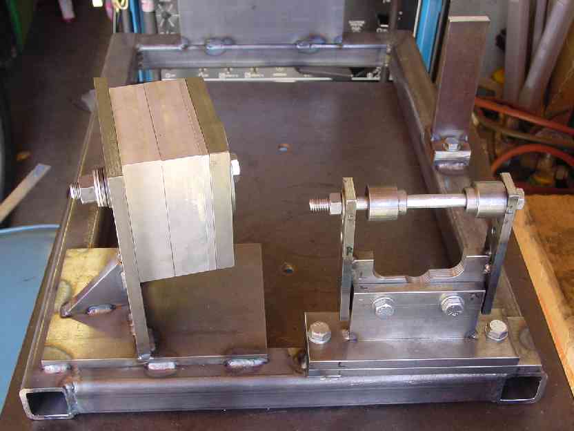
Posted by: slothness Feb 27 2013, 06:40 PM

Posted by: trojanhorsepower Feb 27 2013, 06:45 PM
wow........ that is impressive
Posted by: bigkensteele Feb 27 2013, 10:46 PM
You, my friend, are insane! Incredible work!
Posted by: Bruce Hinds Feb 27 2013, 11:08 PM
Holy mother of God! I thought the Jack was a piece of artwork.
Posted by: andys Feb 28 2013, 12:04 PM
Thanks for all the nice words!
A couple more comments on the trailing arms. Welded structures are subject to movement due mostly to shrinkage from heat. As such, I did get some movement here and there, but the most significant area was the pivot shaft tube. Basically it was no longer straight, so I had to subsequently heat and bend it until it was straight. Also, the bearing bore diameter, to my surprise, shrunk a small amount which I didn't expect since the weld was what I thought was an adequate distance. Now we're talking about tenth's of a thousanth of an inch, but this is a press fit and needs to stay within a suitable range. In the end, the correct final step after welding, would have been to normalize or stress relieve the structure, but that would have added cost, time, and required an alignment fixture....too much added hassle so I didn't do it.
The overall weight of this custom piece is about the same as a stock trailing arm with reinforcement kit, so I think that worked out well. I had considered, and even started machining parts to make an aluminum trailing arm, but the risk just wasn't worth it.......A welded aluminum structure requires a multi step treatment cycle to relieve stresses, normalize, anneal, and heat treat. And in the end, it's still suseptable to sudden fatigue failure. I added a photo of the aluminum bearing carriers that I didn't use.
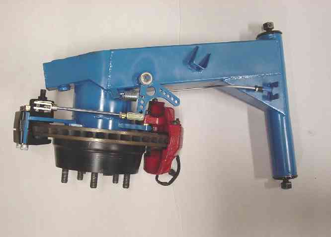
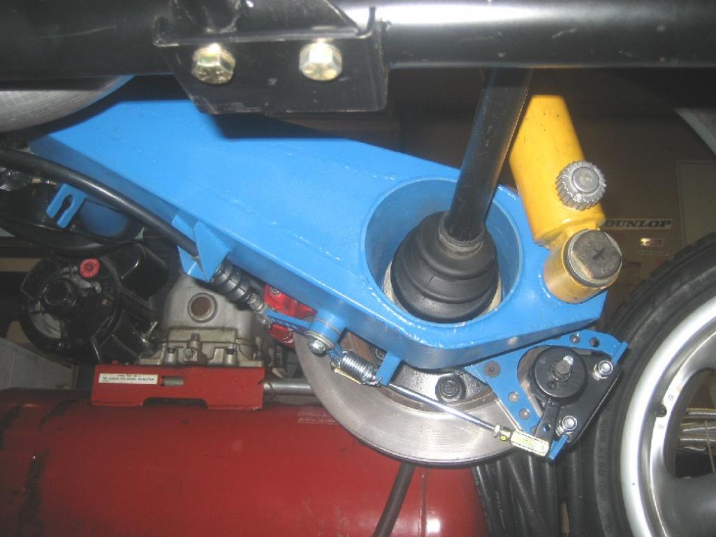
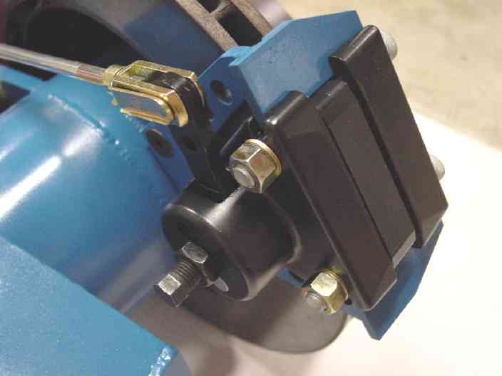
The parking brake is a Wilwood mechanical spot caliper, and I configured the linkage such that the stock 914 parking brake cable and clevis setup could be used without modification. The Wilwood caliper is a floating type which means it sits loosely in it's mount. The result is that it rattles when driving the car; very annoying! What I may do, is design some type of slide cofiguration (pins and bushings) to eliminate the rattle.
So the big unanswered question surely on everyone's mind, is why blue? Had a can of Ford engine enamel.......and now that they're on the car, the color looks kinda cool actually.
I threw in a photo of the stock trailing arm in the weld fixture.
Attached thumbnail(s)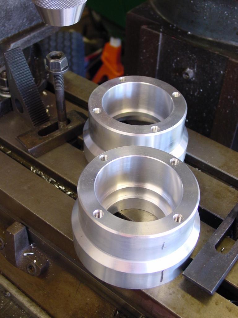
Attached image(s)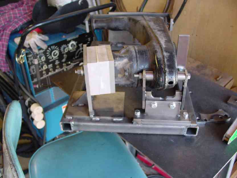
Posted by: get off my lawn Feb 28 2013, 04:34 PM
What color is that jack, fire engine red?
j/k
BTW, this looks like an ad for viagra.
Attached image(s)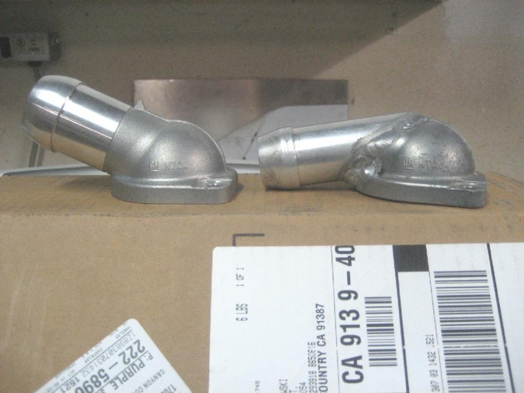
Posted by: andys Mar 4 2013, 02:33 PM
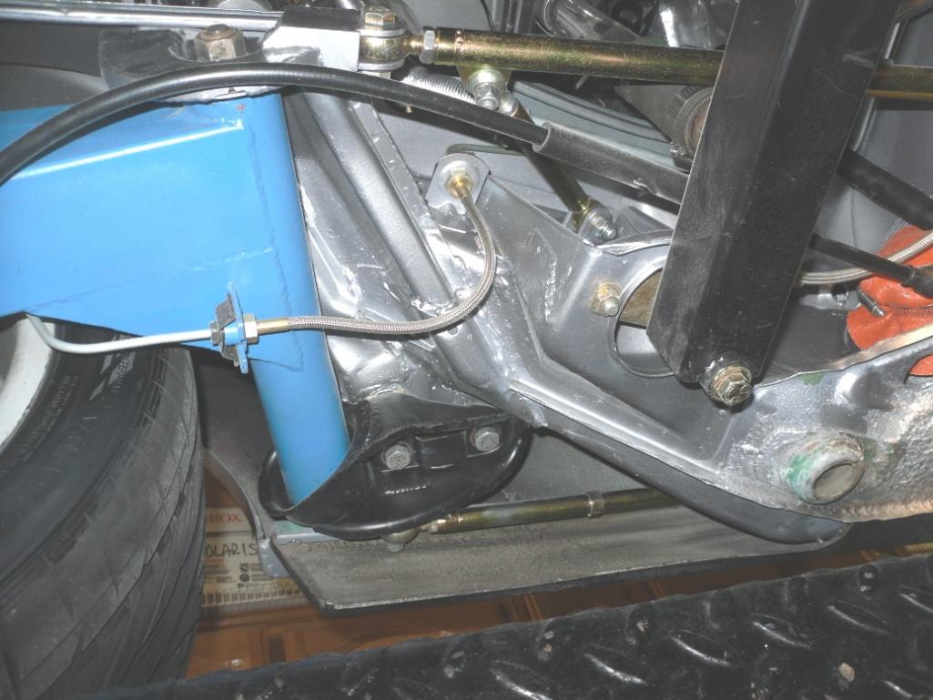
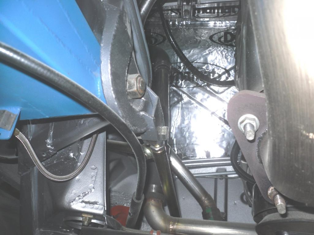
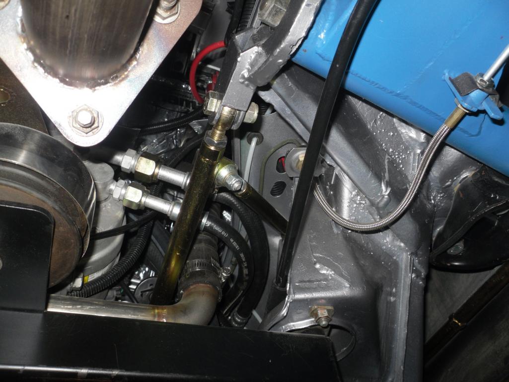
I re-enforced the inner suspension ears with a sort of scab plate and boxed combo along with the traditional link to the firewall. I made cardboard templates for the scab plates, cut out some sheet metal, and TIG welded those into place. As with most inner ears, the hole for the pivot shaft usually gets worn out-of-round, so I made sure to add some weld bead and ream the holes true.
I added some double shear pickup points to mount some removable re-enforcement links. What I decided on, was to make a compound link that has two legs; one goes straight forward to the firewall, and the other angles upward and anchors to just above the motor mount structure. Some heims and threaeded clevis', and it's done......oh, and zinc plated. I don't have any real clear shots of the final installation, but I threw in a few where hopefully you casn pick out the re-enforcement scheme.
Attached thumbnail(s)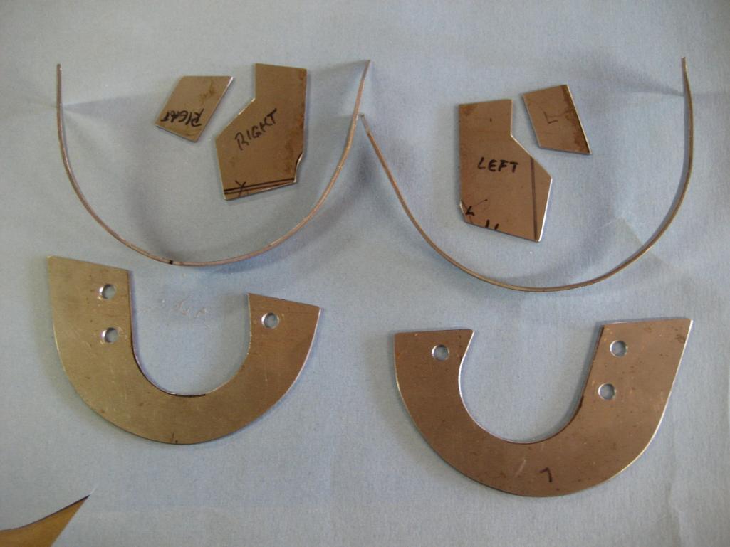
Attached image(s)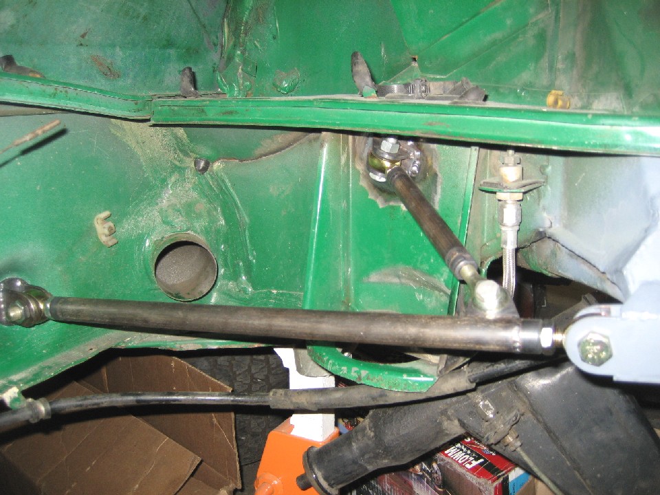
Posted by: JRust Mar 4 2013, 02:41 PM
You really should have just made 2 of everything 
Then sold your leftovers to me cheap  . Your way ahead of me on your conversion. Not to mention your attention to detail is way beyond mine
Posted by: andys Mar 7 2013, 12:49 PM
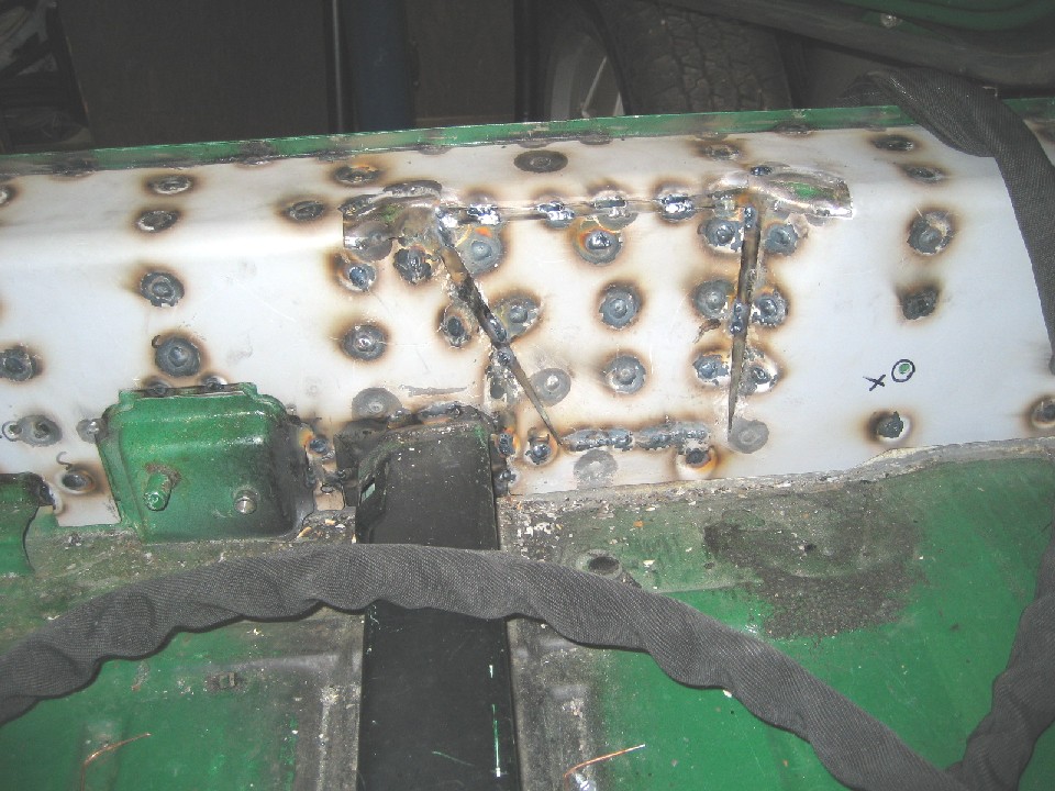
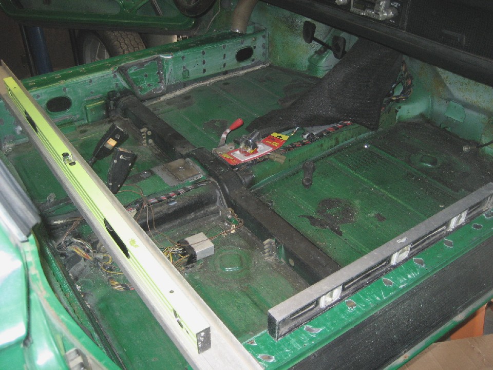
Let's install the Engman chassis stiffening kit. In preparation, I pre-fitted the plates and maked through the holes in order to grind away the paint to expose fresh metal for welding. While trial fitting, I discovered a few problem areas that required some attention.
I first noticed that the plates are not in intimate contact with the longs due to the longs not being flat; some areas are slightly bowed out (convex), while other areas are slightly bowed in (concave). So, the areas that were bowed out, I took a rubber hammer and gently hammered these areas flat. This helped reduce the gap at the bowed in areas to a somewhat reasonable amount. As any welder knows, a gap between plates like this will result in excessive shrinkage, and of course reduces the structural advantage.
I noticed too, that the seat belt anchors did not line up with the pre-cut holes, so some work was needed there. Also, the plate that goes across the rear required clearance notches be added for the ribs in the floor pan. Other areas requiring detailing were additional clearance around the cross brace where it meets the long, re-positioned holes so as to line up with the lower backpad screw holes, and the speaker grill screw holes needed the same attention. Once prepped, the work could start.
The chassis was placed on jackstands (at the donuts) and shimmed level. I first measured the door gaps in three places on each side. Then before welding, I placed a jack under the chassis centered in the middle of the long to where it just started to remove the weight from the the donuts. This was done to as an alternative to removing the doors and installing door braces.
I don't own a MIG welder, so TIG was my only best option, but I did quickly learn that TIG is not the right tool for this operation. Torch in one hand, rod in the other, operate pedal with knee, and contort body in ways never before experienced is just not the way to go. I was careful with my weld sequence to best manage heat build-up. Since I had no door braces, I worked slowly, and stopping often to check the door gaps. I would switch back and forth from the drivers side long to the passenger side long to again, manage the heat. I did this over a span of three days to insure that the door gap shrinkage was minimized. I did tack the rear cross re-enforcement in a couple of spots to hold it in place until the longs were done, then I finished welding that in place. When done with all the welding, I of course ground the welds flush.
Attached image(s)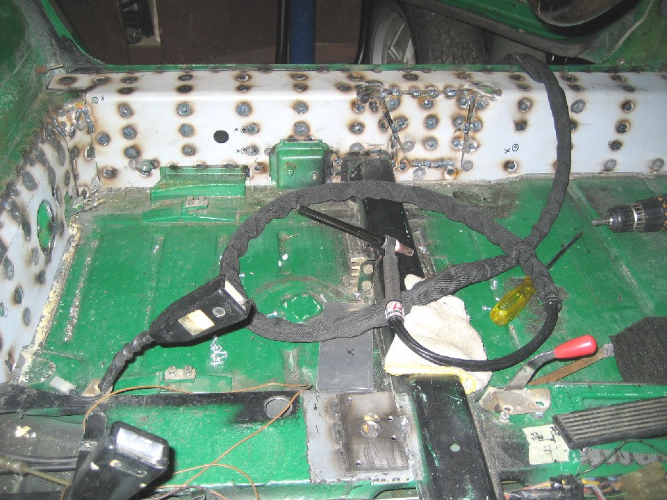
Posted by: andys Mar 7 2013, 01:03 PM
I forgot to mention, that I put a few Tek screws on the long and rear re-enforcement plates to better hold them flush against the chassis prior to welding. They were of course removed, and those holes welded as well.
Andys
Posted by: jd74914 Mar 7 2013, 06:40 PM
I don't own a MIG welder, so TIG was my only best option, but I did quickly learn that TIG is not the right tool for this operation. Torch in one hand, rod in the other, operate pedal with knee, and contort body in ways never before experienced is just not the way to go.
You need a thumb control Andy. They are perfect for stuff that doesn't require real precision when you don't want to use a knee or elbow on the pedal.

Nice job, the car looks great!
Posted by: andys Mar 8 2013, 10:25 AM
You need a thumb control Andy. They are perfect for stuff that doesn't require real precision when you don't want to use a knee or elbow on the pedal.
Nice job, the car looks great!
You know Jim, I got pretty good at the knee/back of knee/leg/etc pedal actuation so that was never the biggest problem. It's the need to get both hands into a confined area (filler rod in one hand, torch in the other) that is the killer. For example, welding the long re-enforcement in the footwell area....My body hurts just thinking about it! A MIG is so much easier for that kind of stuff.
Andy
Posted by: andys Mar 12 2013, 02:07 PM
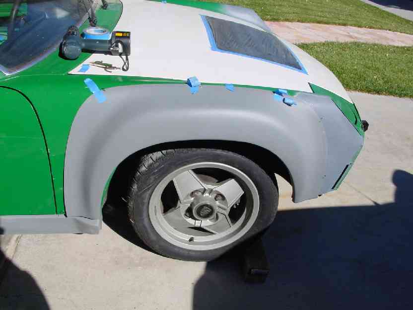
I installed fiberglass flares, and here's why. At the time, the AA steel repro flares were not available, and the only one's that were, were $$$ and not easy to find. Additionally, the fiberglass flares were just a tick wider than the steel, and would accomodate my rear 993 wheels and 255-40-17 tires. As for the wheels, I found a local Ebay seller, so that worked out well. The flares I got from a shop that purchased all the old Mitcom molds, so I bought the flares, rockers, and 916 rear bumper (which I didn't use).
The first thing I did, was to prep the flares by making sure the right to left side periferies were the same. After some minor trimming, they were good. The next bit of prepping, was to grind the high spots on the inside where the flare would be in contact with the body of the car. The result was that the flares were much more flush than before, so it was a worthwhile step. Since I knew the rear tire was a tight fit, I trimmed the inside lip of the rear flares to about 5/8".
I then marked the axle centers (used an aluminum bar across the car with plumb bob's), and taped the flares (centered) into position and marked the body with a Sharpie. I did make sure the flare fit the rockets as well. Removing the flares, I next marked a scribe line 1" to the inside of the first line for some overlap. I then took my sabre saw and cut to the inside line. I taped the flare back into position, then drilled and installed Tek screws every 3" or so. Removed again the flares, and ground away the painted area between the cut and the 1" scribe line.
After some research, I decided on a two-part epoxy product called PC-7. It's mixed viscosity is about that of Bondo, but has a lower shrinkage rate and it's a structural adhesive. Oh, it also has a favorable pot life of 1 hour, and a service cure of 24 hours (7 day full cure). I got mine from The Do-It Center, but it's available at a number of retailers.
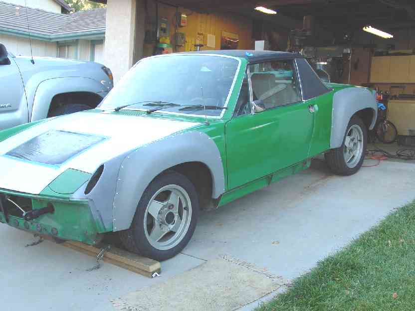
So, I'd trowel on a bead adhesive onto the 1" paint free area of the body (sorry, only photo of this is with wife clowning around), and also "butter" the inside of the flare, then position the flare and drive the Tek screws into place. This operation went really fast. The adhesive that oozed out was simply wiped off, both outside, and underside. Bam! A flared car! Ok, well not quite, as there is a whole lot of filling and sanding necessary to finish the job. If I were to do it again, I'd go with the steel flares just because the fiberglass one's take so much effort to get right. I spent countless hours on the shaping, then spray on some primer in order to spot any imperfections, then do it over and over till it was right.
I discovered a big problem further along in the build when I got the car on the ground for the first go kart test drive (no doors, no glass, etc). The tire would rub against thefront edges of the front flares when turning the wheels even a little bit. A shout out to 914World got me some measurements of the wheel openings of the steel flares......and sure enough, the fiberglass flares were less by about 1 1/2". What I figured was the fiberglass shrunk and the opening closed-up. Needless to say I was PO'd, though I guess I wasn't surprised, since fiberglass parts in general don't hold their shape well when un-supported. The fix was many more hours of pie-cutting, re-glassing, and filling to get both the opening and shape right 
Attached image(s)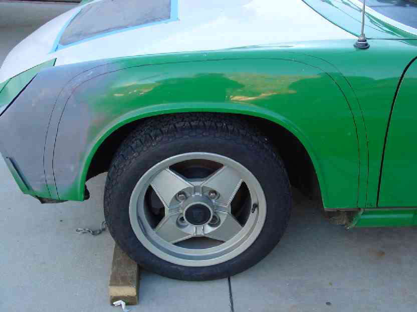
Posted by: andys Mar 13 2013, 12:16 PM
As the cooling system is a crucial part of a V8 conversion, I wanted to be sure to apply good practices for both performance and reliability. I first set out to configure the layout. As such, I decided on thru hood venting rather than the traditional thru fender venting. What I don't care much for with the thru fender venting, is that it creates a big under hood hot box. The thru hood venting, with appropriate ducting, allows the heat to rise naturally thru the opening which is especially important when sitting still in traffic. Down side of thru hood venting is of course it's affect on the car's styling. Enough pontification; lets build a cooling system!
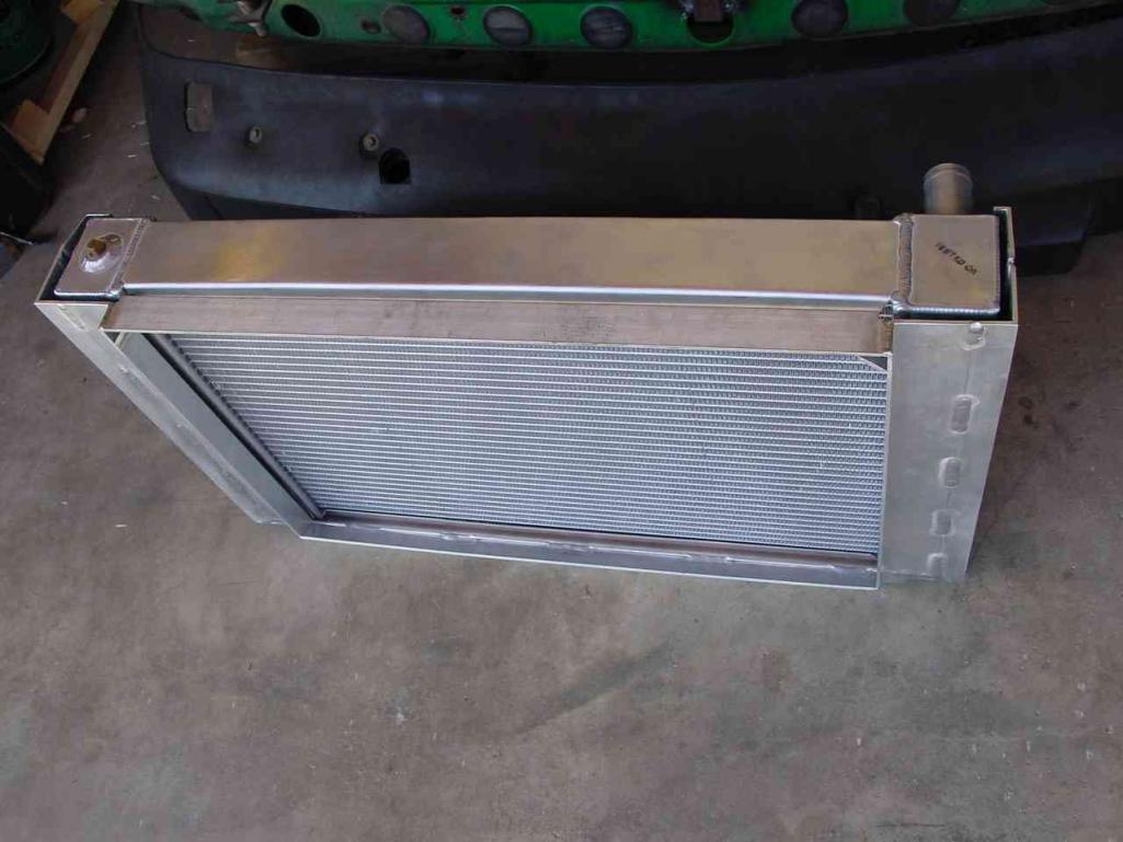
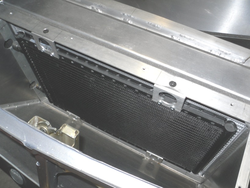
I started with an aluminum radiator from AFCO; P/N 80133N which is an ASA racing radiator, dual pass, cap delete, 27 1/2 x 16 x 3. I see now that Summit sells them, though it's about $100.00 more than I paid a few years ago when I bought directly from AFCO. I'm going to gush a bit about how great these guys at AFCO are to deal with. Again, your typical Mid-Western stock car supplier/manufacturer that is a joy to work with...great attitude, etc. Anyway, the radiator size works out well in the 914; all that was needed was to tip it slightly forward, and it fit.
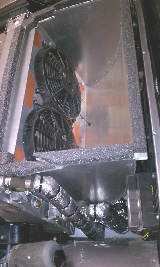
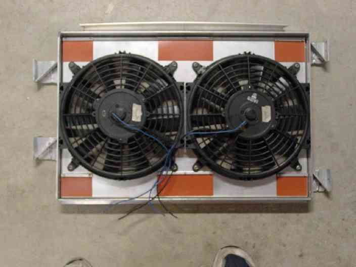
First I cut an opening in the front bulkhead, and re-enforced the center rib with a formed piece of channel to help stiffen the structure. I then determined the most suitable position for the radiator and went about designing a mounting scheme. I did what I've done on race cars, which is to build a U shaped channel lined with foam into which the radiator gets inserted into. This avoids any hard mounting, and completely shock mounts and isolates the radiator. I always cringe when I see folks hard mount radiators. There are of course other ways to shock mount, but this is how I like to do it. I made the U shaped channel out of aluminum with tabs in strategic locations for mounting. For the mounting points, I also shock mounted this structure to the chassis with two rubber isolators on the bottom, and two rubbber grommet mounts on the top. I used two Zirgo 10" puller fans and mounted them to a shroud. I also made some silicone rubber flaps to pass additional air at higher speeds thru the shroud as well. The shroud bolts to the structure.
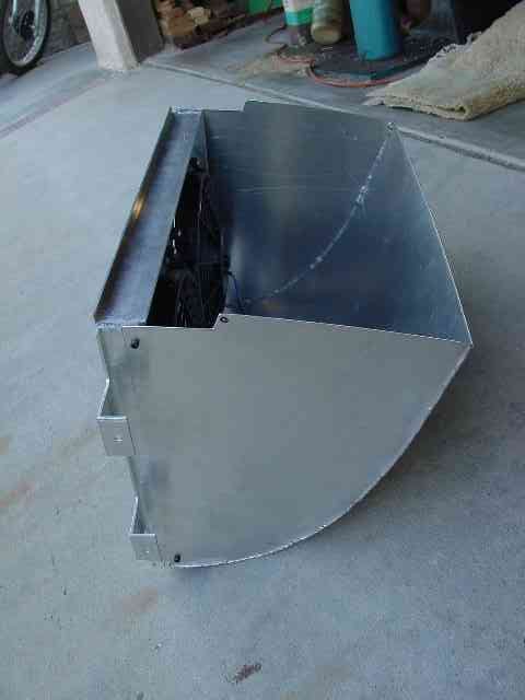
For the ducting, I made some sheet aluminum ducts both front and back that mount to the radiator U structure, but do not fasten to the bulkhead, but stop short with foam gasketing to make the final seal. For the exit side, I made a duct that turns upwards. A foam gasket seals the gap between it and the hood.
The hood vent piece (diffuser) was designed with the help of an Art Center College of Design student, as I have no styling talent what so ever. I made a foam model which I covered with fiberglass and filled and sanded smooth. The size of the opening in the hood is 1.7 times the inlet side to help create the requisite pressure differential to draw the air out (with the help of the vent/diffuser). This diffuser sandwiches a rubber gasket to protect the paint, and is fastened to the hood by stailness button head screws from the underside (I bonded threaded inserts into the diffuser). With all this however, like very much what byndbad914 did with the louvered diffuser on his track car. Looks racey and subtle; if I would have known at the time, I would have simply gone that route instead.
I'll get to the piping in the next post.
Attached thumbnail(s)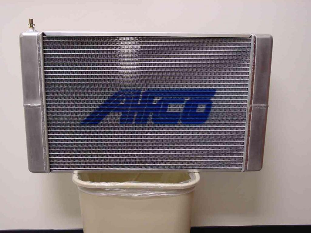
Attached image(s)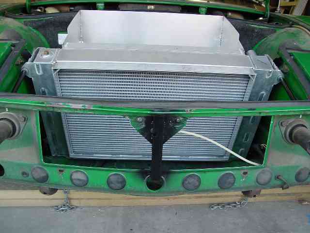
Posted by: quadracerx Mar 13 2013, 01:45 PM
WOW... Nice work!!
Has anyone tried a "cowl induction" style hood?" Think 69 Camaro style. That's what I think I'm going to try when I get to this point....
Posted by: SouthCali914 Mar 14 2013, 12:43 AM
WOW... Nice work!!
Has anyone tried a "cowl induction" style hood?" Think 69 Camaro style. That's what I think I'm going to try when I get to this point....
A cowl induction hood takes advantage of the high pressure zone at the base of the windshield. this would be very detrimental to potential airflow over the radiator. it's intent is to force air from this zone into the intake via ducting built under the hood.
under car, through the wheel wells or ,as the op has done, through the hood are pretty much your only viable choices.
Posted by: andys Mar 14 2013, 01:47 PM
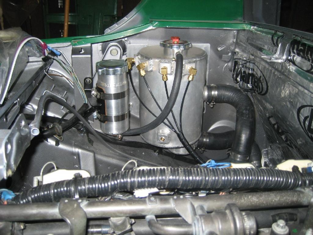
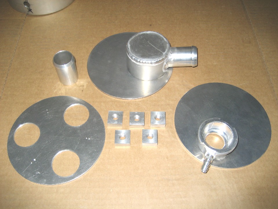
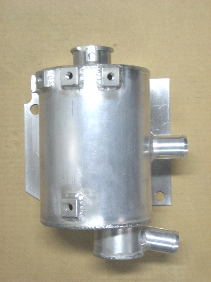
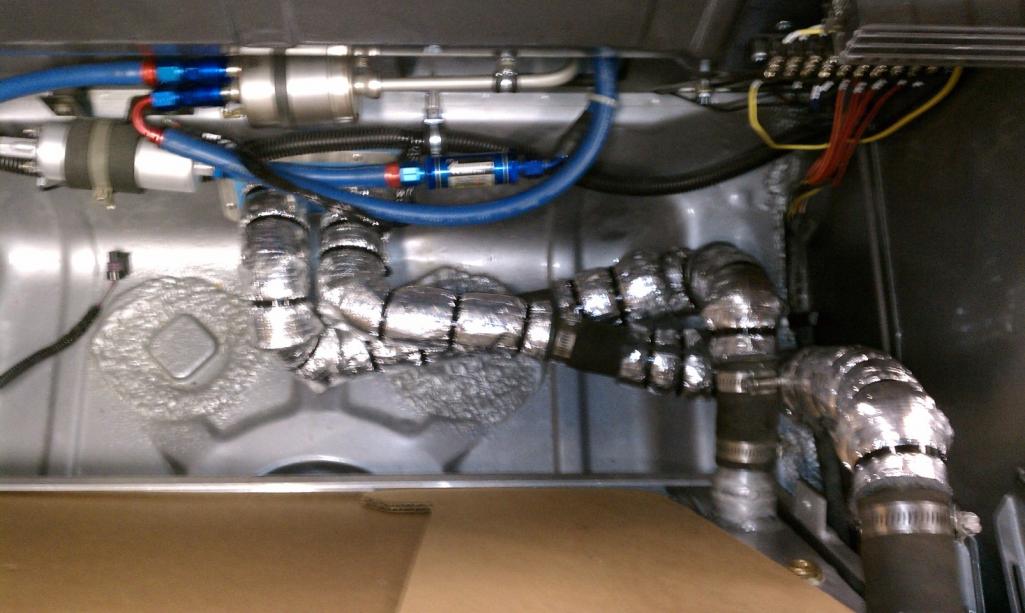
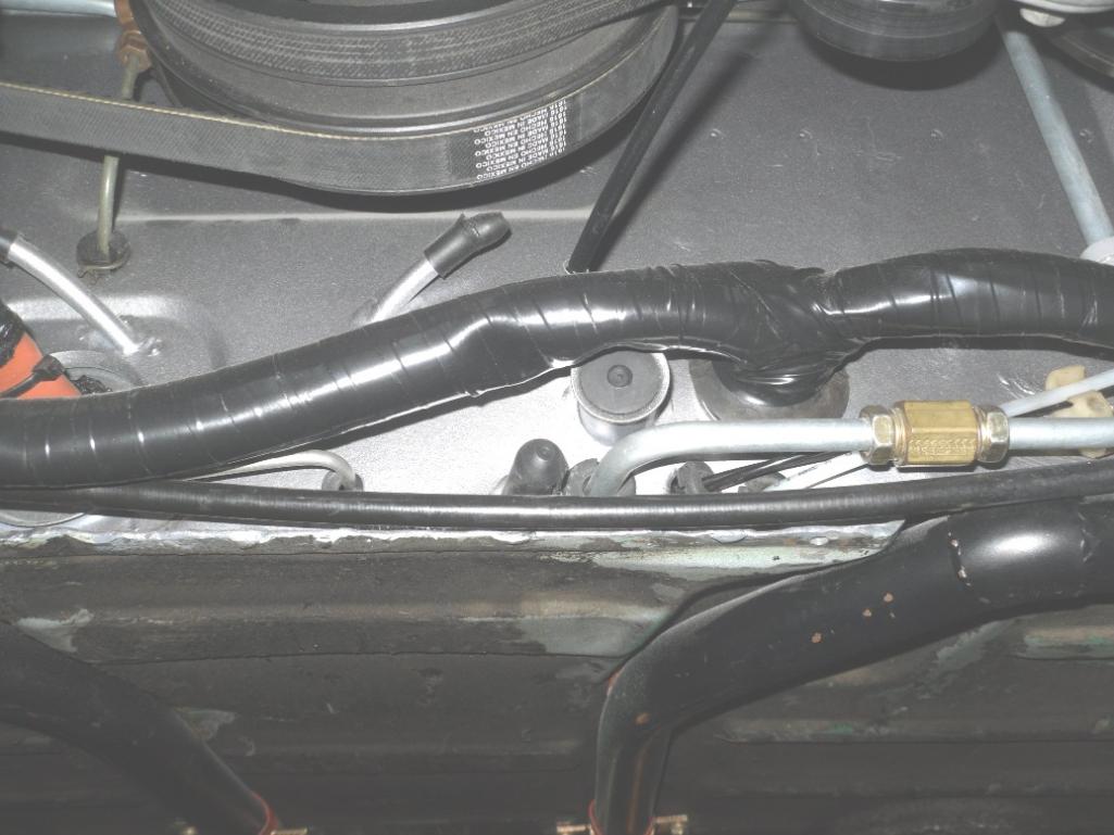
As promised, here's what I did with the radiator water management and piping. I wanted to design a system with the correct elements necessary to ensure good performance. My main focus was on a system that would separate air from the water, and to reduce or remove the possibility of trapping air pockets. To start with, the LS1 motor has 4 steam vents in the heads; the early LS1/LS6 plumbed all four into the top of the radiator, and the later ones use only the front 2 steam vents. The traditional front engined layout tips the motor slightly back so 2 steam vents would be ok, but the 914 layout has the motor sitting level, thus I chose to use all 4 steam vents. Wegner Automotive sells a nice steam vent adapter that has a 1/8 NPT f'male thread complete with o-ring and stainless screw for cheap. I installed those, and used 90 degree compression fittings for 1/8" tubing. I decided to try some 1/8" nylon hard line as it is small and easy to route. You'll see how I ran those to my header/air separator tank.
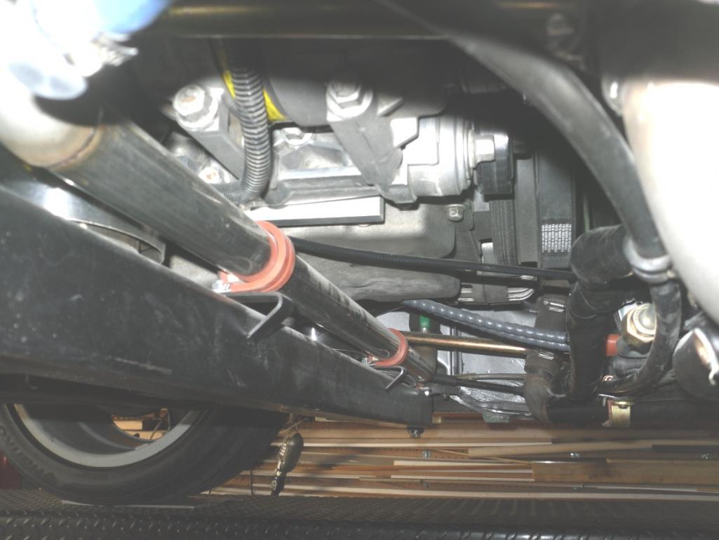
I fabricated an aluminum flow-thru header/air separator tank, and mounted it on the drivers side of the engine compartment. I also fabricated a small purge tank. With this location, I needed to run a line from the right side water pump outlet under the motor to the left side. I made a stainless crossover pipe; I got some stainless 90 degree elbows from McMaster-Carr and welded them in, then mounted it to the motor mount bar with Adel clamps.
I decided to make under car hard lines. I first made a pattern using EMT and EMT bender so that the pipes run in the two depressions in the floor pan. This helped me a lot when making bends in a heavier walled steel tube. I went with mild steel here because it's easy to bend, where stainless thin wall is nearly impossible. After bending, I coated the inside of the steel tubes with POR-15. I did weld thin wall stainless tube ends with hose beads on each end. I attached photos of a beading tool I made and the resultant bead.
I cut a hole in the lower trunk area for the piping to pass through. What I did find was that the 911 aluminum suspension cross member was too bulky, so I used the tubular stock 914 cross member instead.....it was a tight fit. I've got some photos of the under car piping, but can't seem to find them at the moment; maybe later? Anyway, I hope the photos show enough to make sense of it all.
Attached thumbnail(s)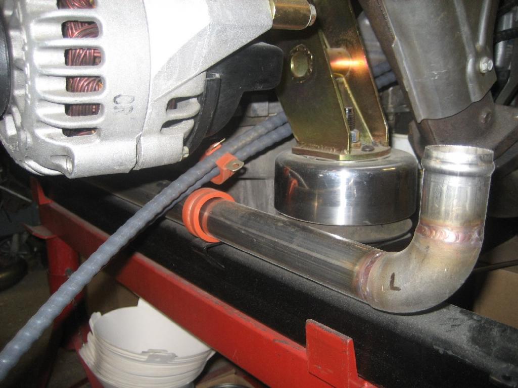
Attached image(s)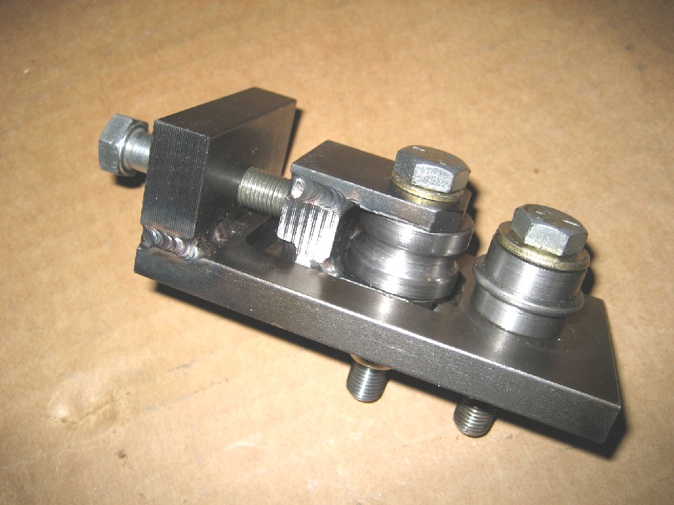
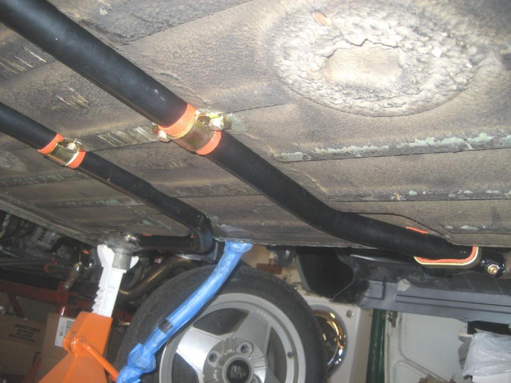
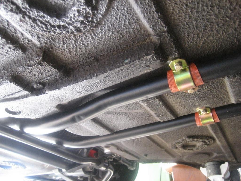
Posted by: andys Mar 14 2013, 04:44 PM
I found a couple of more photos (with the exit ducting removed) of how the piping routed in the front trunk and insulated.
Attached thumbnail(s)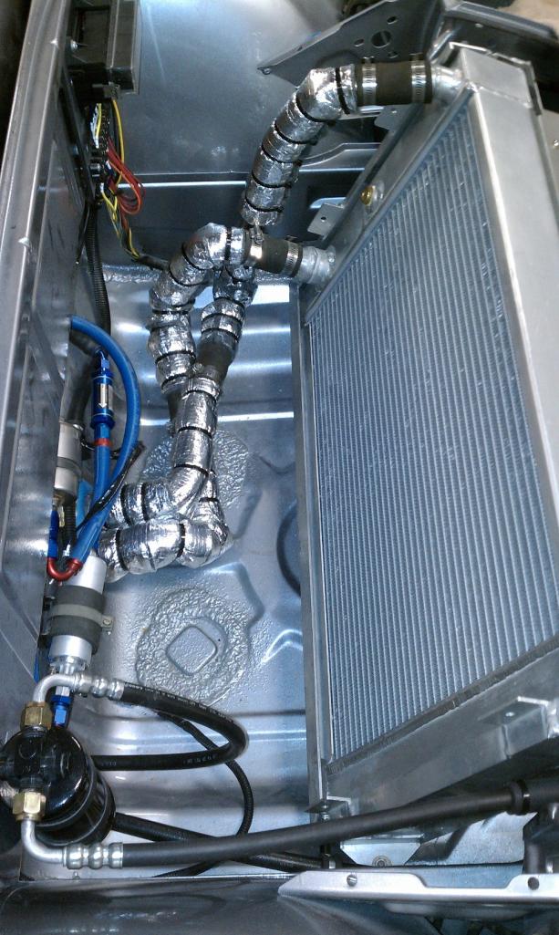
Posted by: tscrihfield Mar 14 2013, 09:42 PM
Andy, this has shown a lot of great, quality work!
Can't wait to see he rest!
Thomas
Posted by: andys Mar 16 2013, 09:37 PM
I stubled across a couple more coolant pipe photos.
Attached thumbnail(s)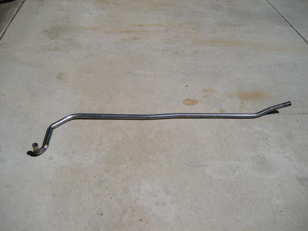
Posted by: andys Mar 20 2013, 12:26 PM
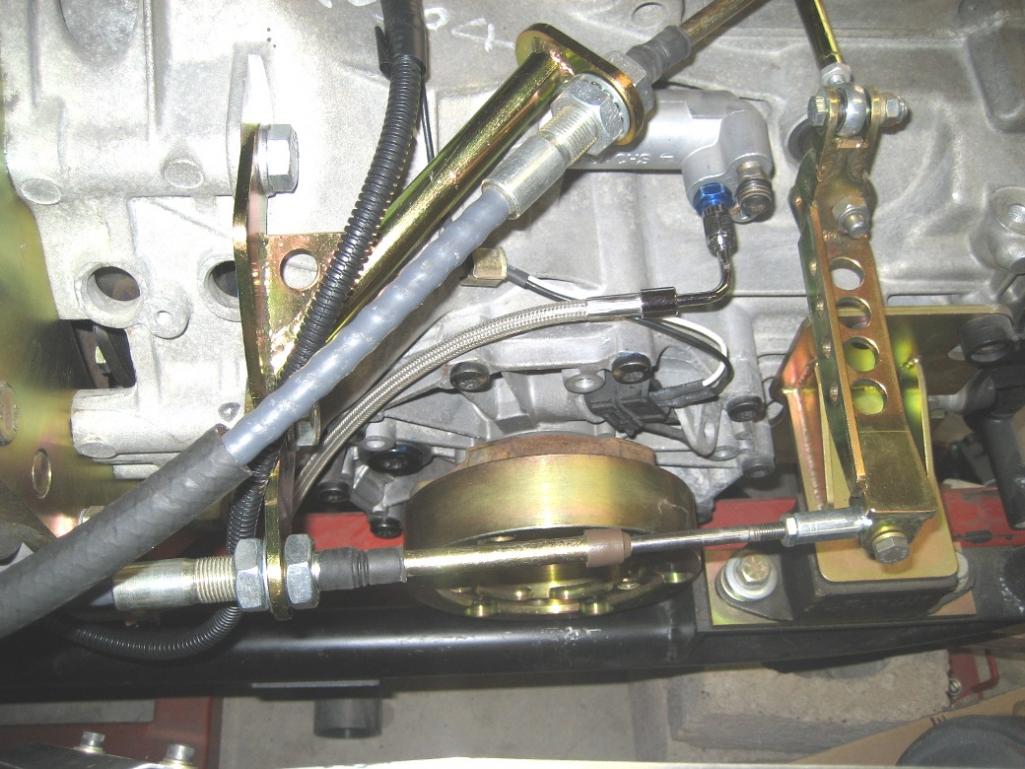
Here's how I did my shift linkage. I know that from time-to-time some have posted cable shifter ideas for the 901/915/Subie/etc. Here's how I did my Audi 01e 6 speed.
I did try at first to prototype a rod linkage, but the resultant angles were just not condusive to good action as the Audi shift shaft is oriented transversely and is high on the housing, so I gave that up pretty quickly.
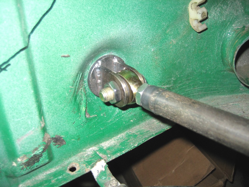
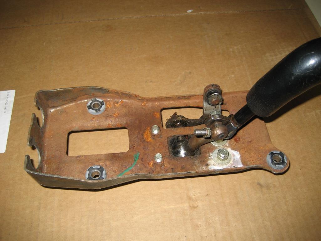
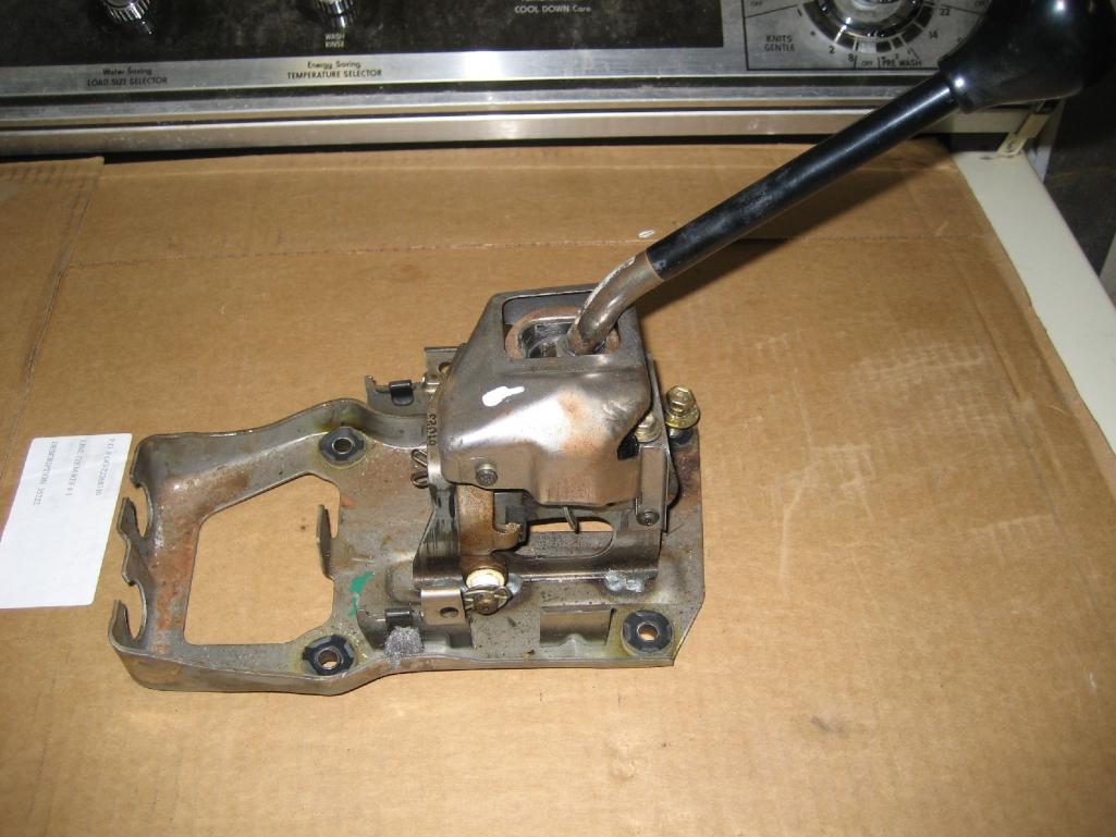
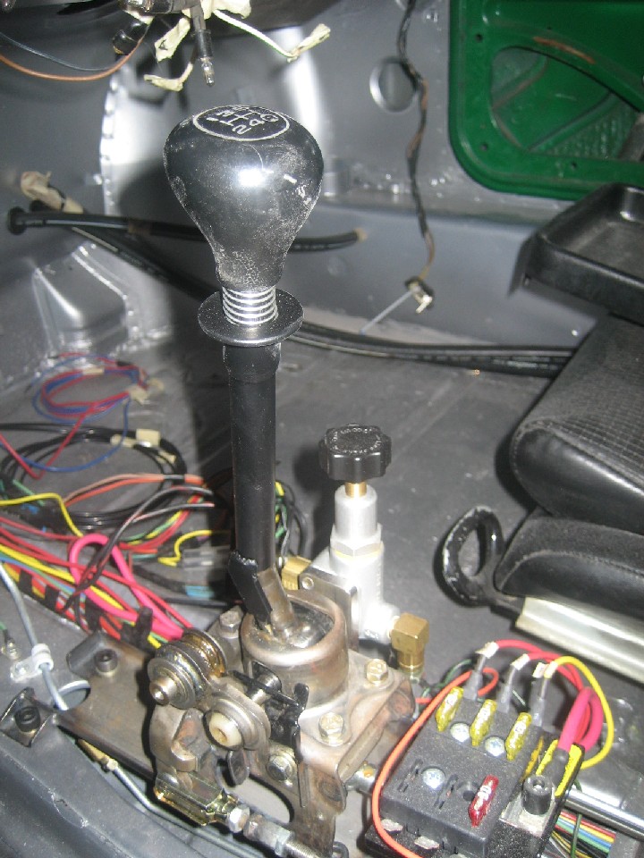
So on to a cable shifter solution, I first thought about designing a cabin shifter to suit all my needs. I quickly found that OEM shifters had nearly all the features I needed, so I went that way instead of designing and fabricating my own. I decided to go with a Toyota shifter. There are others, but I figured the Toyota would be the easiest to find. I didn't consider the Boxster shifter, as it's plastic construction doesn't lend itself well to modification. So off to the local Pick-and-Pull and I struck gold. I found MR2, '90's Celica, and '88 Tercel shifters....I also found a Mitsubishi shifter, but I figured the three Toyota shifters would be plenty enough to choose from. The MR2 shifter was nearly plug-and-play, however it didn't have quite enough gate travel for 3 gates plus the reverse gate for a 6 speed application. Just a quick note; the MR2 shifter in a nice piece for those looking to do a 5 speed shifter. The Tercel shifter was reall quite nice as well, but also suffered from a lack of gate travel. I settled on the Celica shifter mostly beacuse of the ease by which the gate limit stops could be modified. I re-configured the shifter base so that it would mount to the existing 914 shifter bolt pattern, though I did move the shift lever position back about 1 1/2" as the stock 914 position was just a bit of a stretch for me. Also, I wanted to keep the shifter low enough for a subsequent console, so I re-configured the cable bulkheads to maintain a low profile. Because there are so many gates on a 6 speed, I wanted to employ a reverse lock-out. I did this by sliding a thin wall tube over the shift lever that is actuated by a finger flange under the shift knob with a spring to keep it in the down position. At the bottom of the tube, I welded a tab that when in the down position, obstructs the shifter from entering the reverse gate.
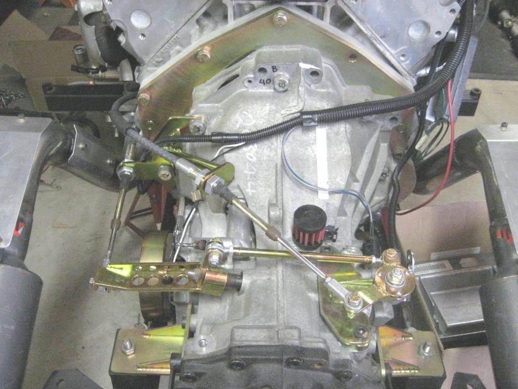
On the transaxle, I set out to design the correct lever ratios to match the travel of the shifter, and to translate the motions for the correct directions necessary. I needed a bellcrank to reverse the gate action, so I went down to my favorite aircraft surplus store, Lucky's Hardware, in Burbank, CA (a great place!) and found a circular flange mounted to a duplex bearing used for small aircraft control systems; $4 each, so I bought 2 of them. I designed and fabricated the linkages, levers, bulkheads, and zinc plated everything.
To get the exact push-pull cable lengths required, I had a coil of high pressure nylon brake line left over from my old GoKart racing days, which I fed through the firewall, to the shifter, and marked. I ordered my push-pull cable from CableCraft, who I've been using for years. A phone call to their tech guy, custom length, any bulkhead, any end, any travel, a credit card, and it's in the mail within a couple of days. Great company to work with!
Hope the attached photos are adequate to show what I did....ask if you have any questions.
Attached thumbnail(s)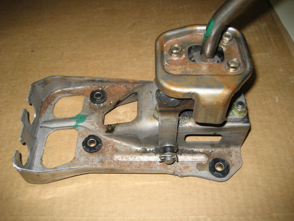
Attached image(s)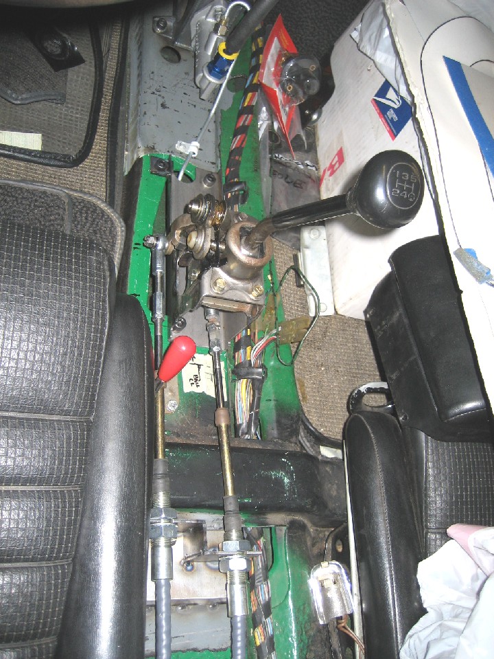
Posted by: andys Mar 26 2013, 02:08 PM
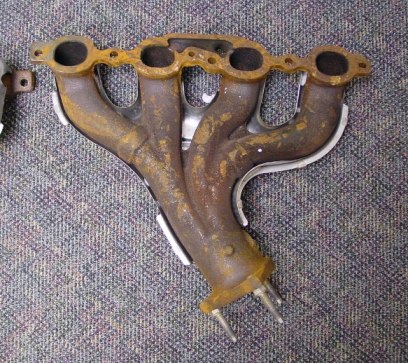
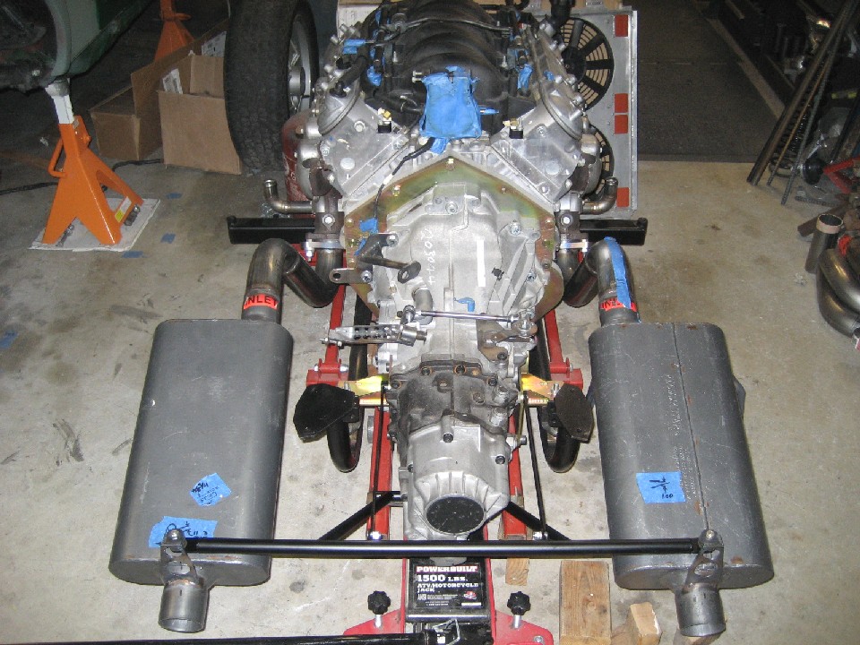
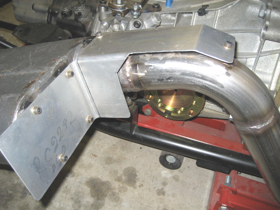
Time to get back to posting more retrospective build photos, so I decided to show the exhaust sytem next.
The stock LS1 headers exit in the wrong place (pointing straight at the axles), so after a little digging, I decided to go with stock LS6 Vette headers. They are thin wall cast iron, tri-Y design, and surprisingly light weight. What I like about these headers, they have some real nice heat shields, aren't prone to leakage like tubing headers, suppport 405HP (which is plenty good for the LS1), and dump on an angle somewhat centered so it's perfect for my application.
The exhaust pipe routing is up-over the axles, which I made from some 2 1/2" stainless mandrel bends from Summit. The flange that bolts to the header wasn't available as an aftermarket part, so I made my own such that it will sandwich the stock Vette donut gasket. The flange is made of mild steel, so I used some 312 stainless rod that's recommended for carbon steel to stainless welds. As an aside, I found this rod is very nice to work with, and I used it on a few other dissimilar welds.
For mufflers, I decided on Flowmaster three chambered stailnless. The three chambered mufflers, according to the Flowmaster noise graphs, significantly reduce the interior noise level; that is something I really wanted. Actually, I needed to determine the available space first, so I mocked-up mufflers from cardboard from the advertised dimensions and moved them around until I got them where I wanted. Since the 01E transaxle is fairly long, there was no space between it and the rear of the car to fit the Camaro style dual inlet/dual outlet muffler that some have used....I think it's a nice solution, but unfortunately not for me.
Once the mufflers were welded in place, I made a brace off the transaxle to mount some rubber isolators to support the weight at the rear. I did add some heat shielding in strategic areas so as to manage the heat. First, I shielded the area adjacent to the shocks, since the muffler and inlet pipe was a bit close. I then added a heat shield where the pipe runs close to the shifter cables. Finally, I installed heat shields to the top of the mufflers to keep the trunk floor from getting too hot; these are made by Flowmaster specifically for the three chambered muffler.
After driving the car, it is a bit loud (exterior noise), but I'm not surprised due to how short the exhaust system is. I know I can quiet it down by adding a cross-over pipe, but there's so little room I'm not sure yet how to route the pipe; I'll have to chew on this for a while. There's also a drone under load from about 1800 - 2000 RPM. After some research, I found that a Helmholz chamber can cancel out this drone. A closed end pipe, regardless of routing, placed preferably just ahead of the muffler, calculated to the proper length (wave speed, number of pulses, frequency, etc) can cancel out the resonance (drone). It's a tidy solution that I may employ once I figure out the cross-over pipe.
Attached thumbnail(s)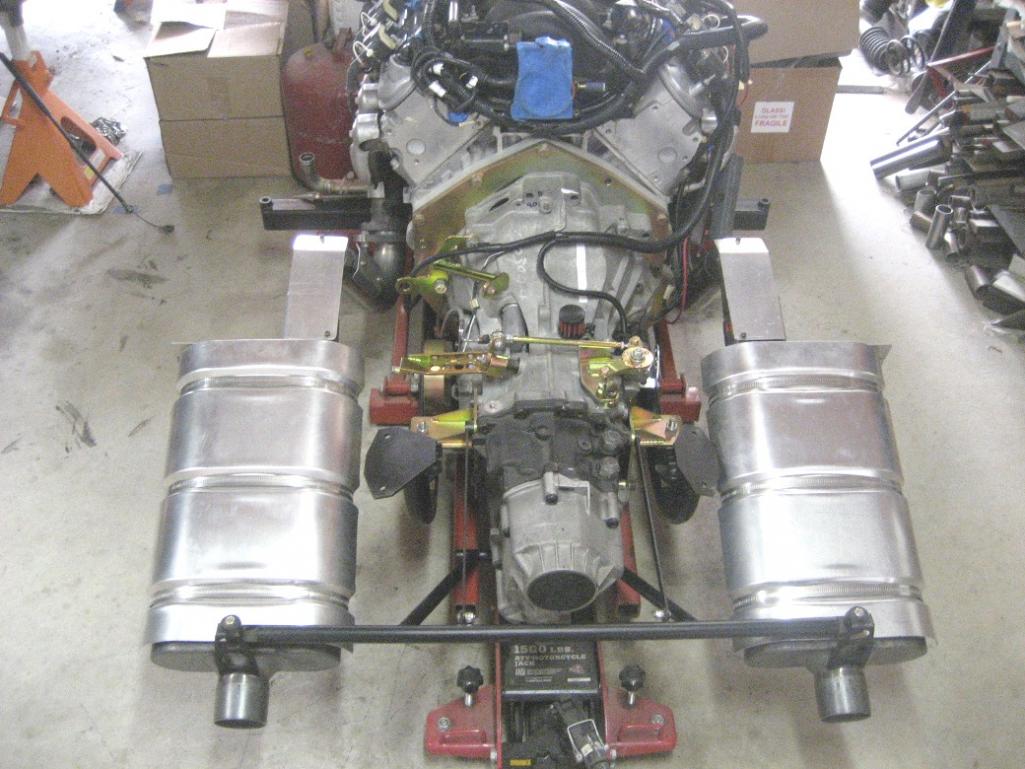
Attached image(s)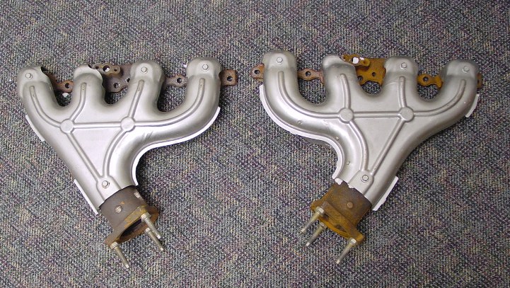

Posted by: andys Mar 28 2013, 03:28 PM
Thought I'd go through the fuel system next. The LS1 EFI system requires 58 psi. The PCM runs the fuel pump for 3 seconds when the key is on. The fuel pump resumes running once the PCM senses the crank rotating. So the basic fuel system has an external electric fuel pump which feeds a bypass style fuel pressure regulator with one line running to the motor, and the other returning to the fuel tank.
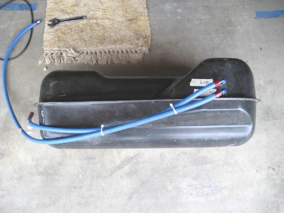
In order to adapt -6AN fittings to the stock 914 fuel tank, I tapped the exisiting inlet and outlet bungs to 3/8NPT....I got this tip from 914WORLD; Thanks! I installed some -6AN X 3/8NPT fittings. What I did on the outlet fitting, was to silver braze a tube and screen (sock) to mimic the 914 in tank screen (actually a VW part) to strain out any big particles. I used Summit Twist Tite push on hose and fittings that's good for 250psi. The feed hose goes through an Earl's 100 micron course filter before entering the Walbro 255 electric fuel pump. One of the two sure death's of this type of pump is particulate contamination, so an additional $50 for the pre-filter is worth it. The high pressure side of the pump feeds into a Vette filter/regulator to bring the pressure down to 58psi. It has a bypass which is plumbed back to the the orignal 914 return line bung. The regulated pressure feed hose goes to a thru-tunnel steel tube, but more on that in a minute. The Vette filter/regulator uses GM type push-on connections; one 3/8' male inlet, one 5/16" male return, and one 3/8" female out. To couple the two male fittings to -6AN, Russell makes adapter fittings, but here's a work of caution: The early style uses a plastic retaining clip that reportedly fails on occasion, according to experiences on the LS1 boards where some fires resulted. Russell subsequently offered a re-designed adapter that employs a positive locking system (644120, 3/8" x -6AN, and 644110, 5/16" x -6AN). The adapters shown in my photo, are the early stlye which I replaced as soon as I read the failure accounts. For the regulated side with the 3/8" female connector, I bought from NAPA a steel adapter tube that had the appropriate swaged male ends, cut one end off, and installed a 45 degree flare nut and flared the othe end. I then made a 180 degree bend to better route the hose under the tank and to the through tunnel steel tube. I purposely made the hoses long enough to allow me to pull the fuel tank up high enough to service anything underneath it without having to romove the hose fittings.
Now to the steel through tunnel line. Since I knew I wanted a steel line with fittings capable of sealing 58psi fuel pressure safely, I decided on a 60" pre-made 3/8" steel brake line with 45 degree flared ends. Here's why I went this route: NAPA offers brass 45 degree flare 3/8" x -6AN push-on high pressure hose adapters in both male and female. This kept things really simple without the need for all kinds of fittings cobbled together. The brake line was bent to shape by trial and error untill it had the shape I was looking for. It passes through the stock 914 rubber fuel line grommet at the front. I did have to slit the grommet to get the line in it, then I plugged the return line hole and pushed the grommet into place. The brake line at the engine bay makes a 90 degree bend towards the passenger side. Here, I added a flare line coupling and used a second pre-made brake line formed to run a path up, then turn towards the passenger side under the engine shelf, all hung from Adel clamps. This line stops just above the engine shelf where another NAPA flare to -6AN hose fitting is used. With another Summit hose, it runs to the LS1 fuel rail through a heat reflective tube. The fitting on the fuel rail in also a GM push-on, so another Russell adapter fitting was used there.
That was long winded for sure, but hope it helps detail what the photos don't show.
Attached thumbnail(s)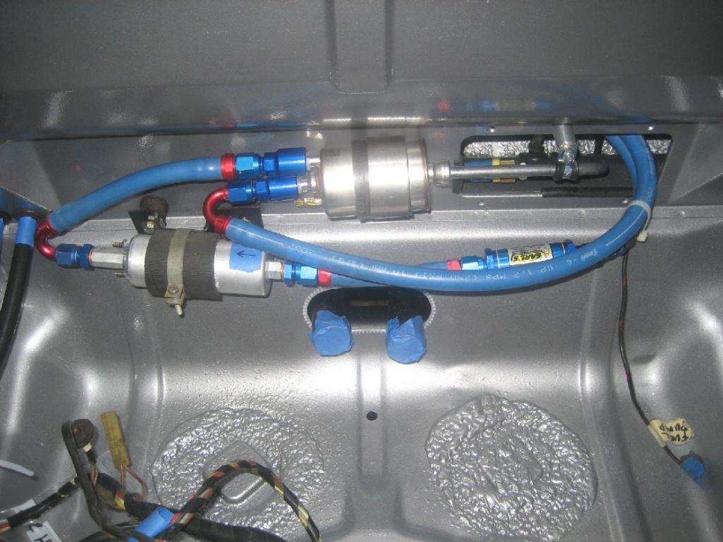
Attached image(s)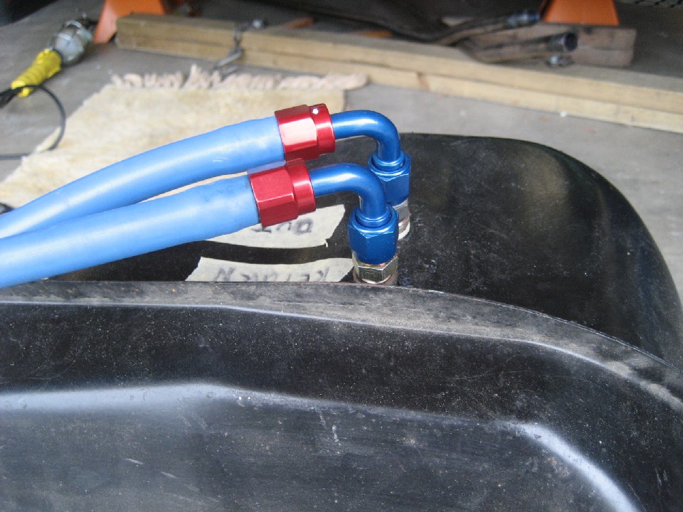
Posted by: dflesburg Mar 29 2013, 09:08 AM
Wow, amazing work, the only comment I have is why fiberglass flares when you could get steel in Atlanta for cheaper than I got mine back in 1991 from Stoddard...
Posted by: andys Mar 29 2013, 09:17 AM
The AA steel flares were not yet available at the time I needed them.
Andys
Posted by: DBCooper Mar 29 2013, 09:30 AM
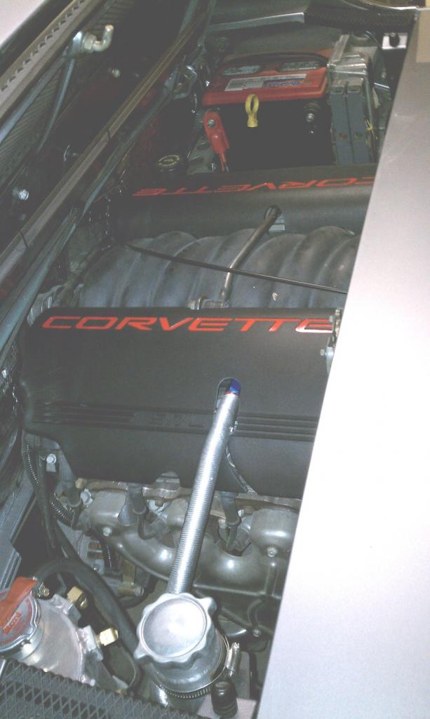
Looks excellent, and like a whole lot of fun. I personally would take off those Corvette plastic covers though. I like the way that engine looks without them and it provokes far more mystery and trepidation among people, even car guys, who peek in there. I LOVE it when car guys can't explain to their wives what they're looking at.
Posted by: andys Mar 29 2013, 10:10 AM
Looks excellent, and like a whole lot of fun. I personally would take off those Corvette plastic covers though. I like the way that engine looks without them and it provokes far more mystery and trepidation among people, even car guys, who peek in there. I LOVE it when car guys can't explain to their wives what they're looking at.
Yeah, I'm not a fan of the CORVETTE lettering; too streetrodish for me. I actually do like that they cover the mess of coils and wires, and cleans-up the engine a lot. My original plan was to sand/fill/prime/paint the Vette coil covers same color as the body. I've seen some done this way, and it looks really sharp....but it's a lot of work to do it right, so I just stuck them on as-is for the time being. I'm not worried about explaining anything to my wife, cause she doesn't care.
Andys
Posted by: Rand Mar 29 2013, 10:42 AM
But if you have that thing out somewhere and some hotrod guy's wife asks him what engine it is and he fumbles a story, *that's* funny. 
Amazing build. Thanks for sharing here.
Posted by: dfelz Mar 29 2013, 01:09 PM
Great build Andy, your work is top notch and looks like nothing was left unnoticed!
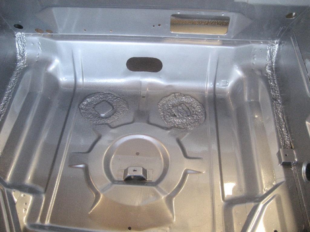
In your gas tank compartment, what is the orange material you used as a replacement for the foam pads?? I have been looking for a suitable material for my gas tank compartment.... Thanks
Posted by: andys Mar 29 2013, 01:41 PM
Great build Andy, your work is top notch and looks like nothing was left unnoticed!
In your gas tank compartment, what is the orange material you used as a replacement for the foam pads?? I have been looking for a suitable material for my gas tank compartment.... Thanks
Thanks, David! Those orange pads are 3/16" textured finish adhesive back silicone foam fom McMaster-Carr p/n 8623K249....too high tech for me, but it was left over from a job at work......Will probably outlast the car.
Andys
Posted by: dfelz Mar 29 2013, 02:28 PM
Awesome, thanks! I love McMaster, they have everything!! and i can go pick it up too! (One perk of living in LA) Hope you dont mind me asking, but what do you do for a living that made you soo good at building sweet cars?
Next time i go to six flags i will probably feel a strong urge to come say hi and see your sexy teener
Posted by: andys Mar 29 2013, 02:49 PM
Awesome, thanks! I love McMaster, they have everything!! and i can go pick it up too! (One perk of living in LA) Hope you dont mind me asking, but what do you do for a living that made you soo good at building sweet cars?
Next time i go to six flags i will probably feel a strong urge to come say hi and see your sexy teener
Engineer for an implantable medical device research foundation, however I've been around racing and working on cars my whole life.
Yeah, drop me a line should you plan on Magic Mountain.
Andys
Posted by: DBCooper Mar 29 2013, 04:28 PM
Ha ha ha, yeah, I can understand that. But I didn't mean her as much as the crowd you always attract at gas stations and convenience stores. You know, the ones who start out by saying "I had one of those a long time..." then go quiet when they notice the engine compartment. It's evil, but it's fun to see them squirm in front of their wives.
Posted by: dfelz Mar 29 2013, 04:35 PM
Awesome, thanks! I love McMaster, they have everything!! and i can go pick it up too! (One perk of living in LA) Hope you dont mind me asking, but what do you do for a living that made you soo good at building sweet cars?
Next time i go to six flags i will probably feel a strong urge to come say hi and see your sexy teener
Engineer for an implantable medical device research foundation
Andys
What company!?! I did a 6 month internship last year at St. Jude Medical over in Sylmar as a Hardware Engineer!
Posted by: 914GT Mar 29 2013, 06:18 PM
Andys
I've been following your build thread for awhile now, and just wanted to say yours is one of the sweetest looking and well thought out conversions I've ever seen. I've done two V8 conversions so far and it's great seeing all the thought and planning you've put into this. The details such as the heat shields is some good engineering work and basically you are designing out a lot of bugs before they ever happen. I'm sure once you get it on the road you'll be chasing a few more, as with any project as complex as this. But I bet they will be minor tweaks if anything. Hope you enjoy driving yours as much as I do mine. For sure yours will show how these conversions ought to be done, instead of the shoddy builds that have given them a bad reputation.
Guy
Posted by: andys Mar 30 2013, 08:40 PM
Awesome, thanks! I love McMaster, they have everything!! and i can go pick it up too! (One perk of living in LA) Hope you dont mind me asking, but what do you do for a living that made you soo good at building sweet cars?
Next time i go to six flags i will probably feel a strong urge to come say hi and see your sexy teener
Engineer for an implantable medical device research foundation
Andys
What company!?! I did a 6 month internship last year at St. Jude Medical over in Sylmar as a Hardware Engineer!
David,
Small world! St. Jude was originally Pacesetter Sys. Inc. which was started by Al Mann. I worked at Pacesetter for 19 years, then moved to The Al Mann Foundation for Sientific Research for 16 years.....Still there.
Andys
Posted by: andys Mar 30 2013, 08:59 PM
Andys
I've been following your build thread for awhile now, and just wanted to say yours is one of the sweetest looking and well thought out conversions I've ever seen. I've done two V8 conversions so far and it's great seeing all the thought and planning you've put into this. The details such as the heat shields is some good engineering work and basically you are designing out a lot of bugs before they ever happen. I'm sure once you get it on the road you'll be chasing a few more, as with any project as complex as this. But I bet they will be minor tweaks if anything. Hope you enjoy driving yours as much as I do mine. For sure yours will show how these conversions ought to be done, instead of the shoddy builds that have given them a bad reputation.
Guy
Guy,
Thanks for the kind words; I appreciate it.
Racing taught me (old cliché here) "To finish first, you must first finish" so reliability and durability must be balanced with performance goals. I'm also a bit anal when it comes to mechanical stuff, so anticipating problems is something I pain over a great deal
I hope soon to take it out to The Streets of Willow for one of those HPDE's and use it as a testing session to dial in the suspension.Anyway, thanks again,
Andys
Posted by: dfelz Mar 31 2013, 11:38 AM
Awesome, thanks! I love McMaster, they have everything!! and i can go pick it up too! (One perk of living in LA) Hope you dont mind me asking, but what do you do for a living that made you soo good at building sweet cars?
Next time i go to six flags i will probably feel a strong urge to come say hi and see your sexy teener
Engineer for an implantable medical device research foundation
Andys
What company!?! I did a 6 month internship last year at St. Jude Medical over in Sylmar as a Hardware Engineer!
David,
Small world! St. Jude was originally Pacesetter Sys. Inc. which was started by Al Mann. I worked at Pacesetter for 19 years, then moved to The Al Mann Foundation for Sientific Research for 16 years.....Still there.
Andys
Thats crazy! What a small world it is! No I am not currently working there, it was just for 6 months and then had to go back to school to finish up my ME undergrad. I will apply to work there though for after I graduate next March, I really enjoyed working at SJM, was a great experience for me!
I am assuming The Al Mann Foundation is focused on implantable devices for cardiac stimulation/support?
David
Posted by: kg6dxn Mar 31 2013, 11:58 AM
I nominate this thread for the Classics.
It will go down as one of the best engineered conversions in the 914 World.

Posted by: BIGKAT_83 Mar 31 2013, 12:33 PM

Andy has set a new standard for everyone to shoot for.
Bob
Posted by: andys Apr 5 2013, 07:19 PM
I'm jumping around a bit, however lets go ahead and paint the car.
I'll start with paint and materials. I went with PPG base coat/clear coat (Deltron 2000 DBC base, and Deltron DCU2010 clear). The color is M7Z GT Silber (silver), which is a Porsche color. I chose this particular silver because it has a deep rich look, rather than some of the more pale silver's. Interesting that when I watched the store mix the paint, they added black to it hence the darkness and richness.....at least that's my take.
I bought a sanding block kit from Summit (Dura-Block) and some rolls of various grit 2 3/4" wide adhesive backed sandpaper also from Summit. The sandpaper is Carborundom Gold (not to be confused with Kona ), which costs 1/3 less than the 3M brand. I already had some long boards, and various other sanding blocks, and used them all.
For Primer, I used PPG Deltron DP40LF epoxy, and chose the straight gray color to maintain the deep look in the color coat. For body filler I used , for the first time, Rage Gold which I like very much. I strongly recommend this product; super quality in my book. For high build primer, I used Shop Line JP205 gray polyester, which is made by PPG.
There was an assortment of dings and dents that required the requisite bodywork, but most, unfortunately, were on blind panels, so I couldn't get a dolly behind the dents. I made ample use of my HF stud gun in these areas and used the body filler as required. To get the filling and blending just right, it took A LOT OF WORK for what seemed like never ending sanding, priming, sanding, priming....well you get the picture. I don't think I'll ever do another one again!
I ended up with three HVLP guns. For the epoxy primer, I used the slightly better quality HF gun with a 1.4 nozzle. For the high build primer, I used a cheapie HF gun and drilled out the nozzle to 1.9; it worked out very well for this application @ 40psi. For the base and clear, I used a quality Eastwood gun with a 1.4 nozzle. I had other nozzles, but this worked well in both cases.
I rented a spray booth from a guy that does a lot of the local hotrod work (as a retirement hobby), and I took a lot of advice from him. Thanks Howard! I towed the car there, which was about 12 miles, and spent two looong days priming, base, and clear coating. I layed down three coats of base, and tthree coats of clear. I used about 2 1/2 quarts of base, and about 3 1/2 quarts of clear for both inside, and out. The doors were removed, as were the hood, trunk, targa, and engine cover and painted while hanging in the booth. After three days (I think), I color sanded the clear (1000, then 1200) before it got too hard. I left it in the color sanded state until I assembled the car, and then went about buffing it out. I used 3M Perfect-It #6085 (step 1), and Perfect-It #6064 (step 2). My biggest hurdle was finding a machine pad that I was happy with, and went through several before I got something that produced a good result. I could have gone finer yet, but this is not a show quality car and I stopped there.
All this is from memory (poor memeory at that!), so perhaps I've left something out or got something wrong, but you get the idea. As always, pleaes ask.
Andys
Attached thumbnail(s)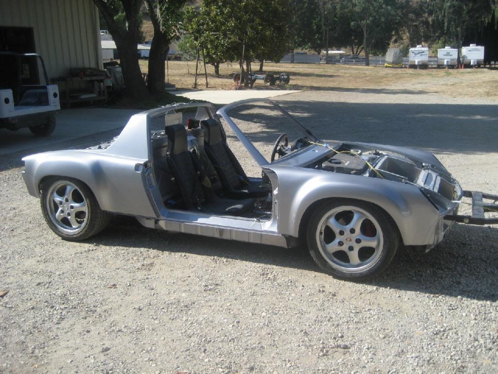
Posted by: andys Apr 11 2013, 12:20 PM
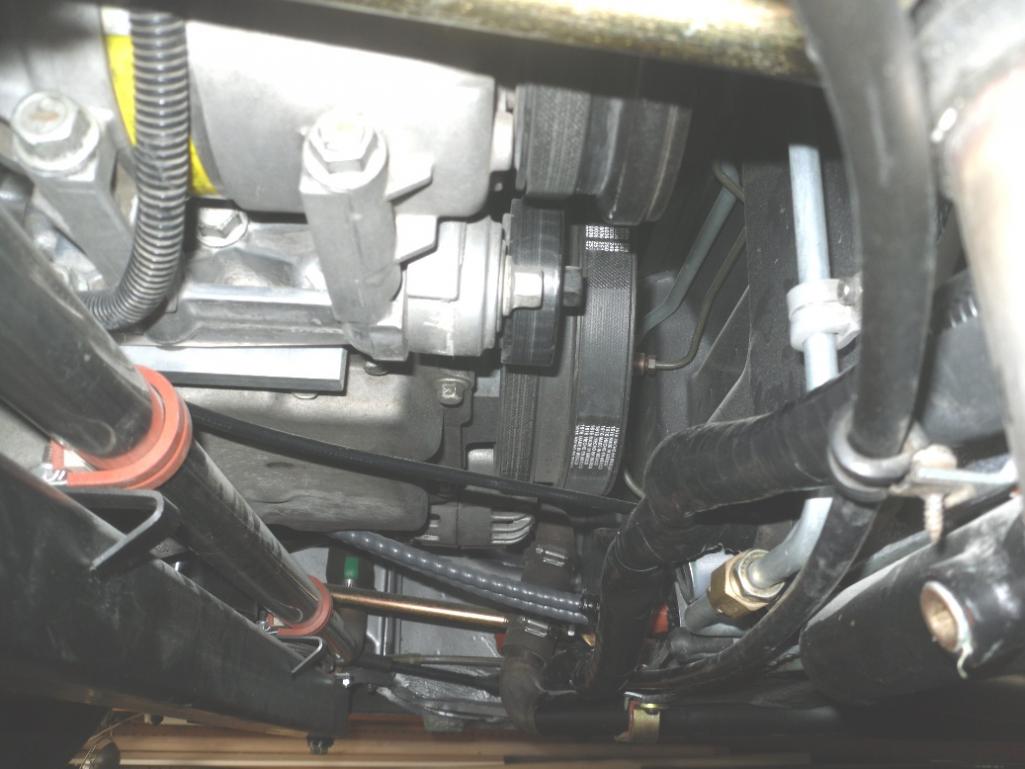
Thought I'd take y'all through the AC system. I posted some of these photos before in answer to another thread, but hopefully these will provide more info.
I bought a Hot Rod Air under dash evaporator based on it's compatability with my existing LS1 variable volume compressor. Vintage air claims their system is not compatible with this copressor, therefore my decision. The Hot Rod Air evaporator includes heat, and has defrost. The Hot Rod Air guys were very helpful, however they apparently went out of business not long after I received the unt from them  For the condensor, I bought a Vintage Air 12"x20". Since the LS1 PCM has the capability to control the AC, I decided to run a GM AC refrigerant pressure sensor rather than a trinary switch. The GM PCM controls the compressor cycling from the AC request signal output, turns on the radiator fans (and truns them off over 40 MPH), and of course monitors the pressure.
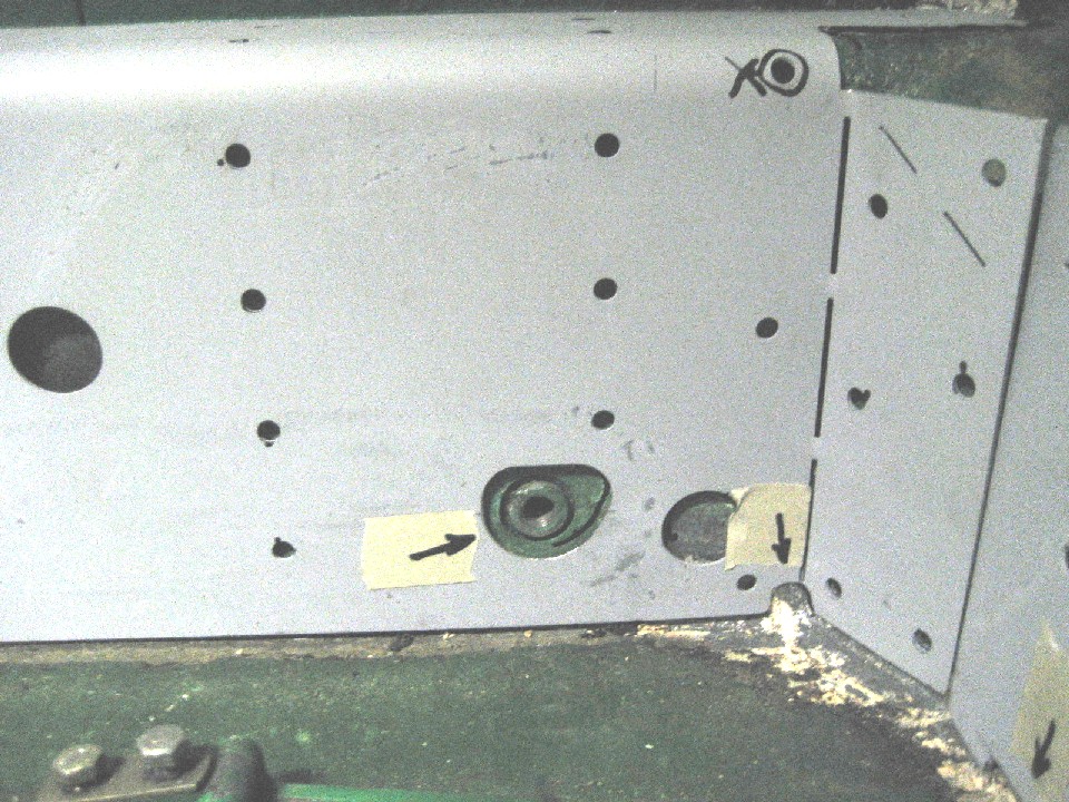
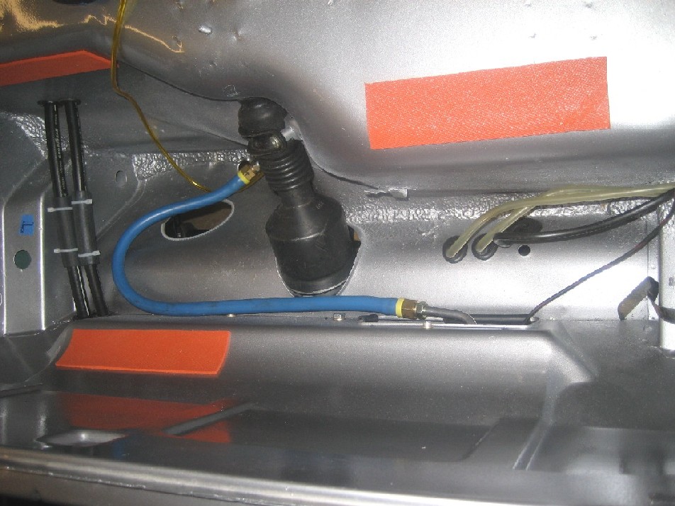
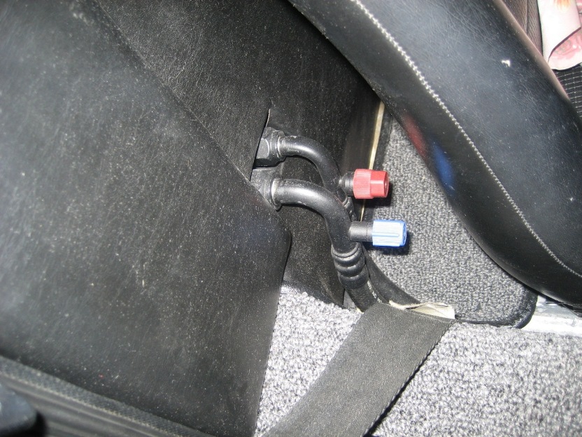
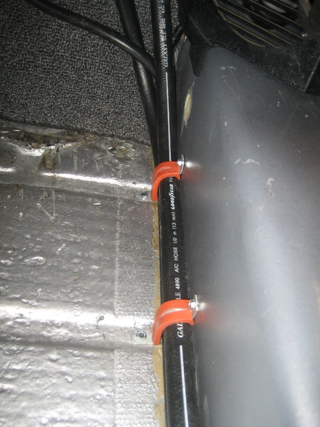
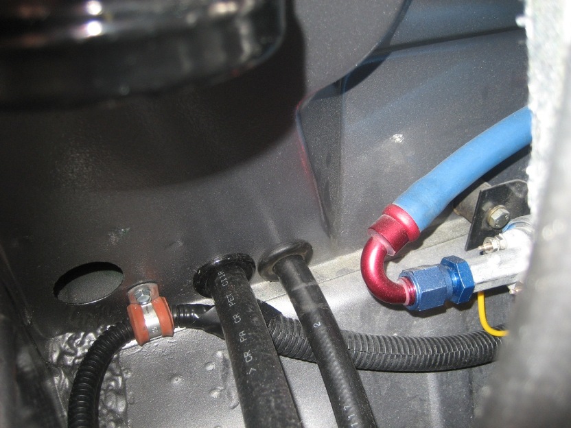
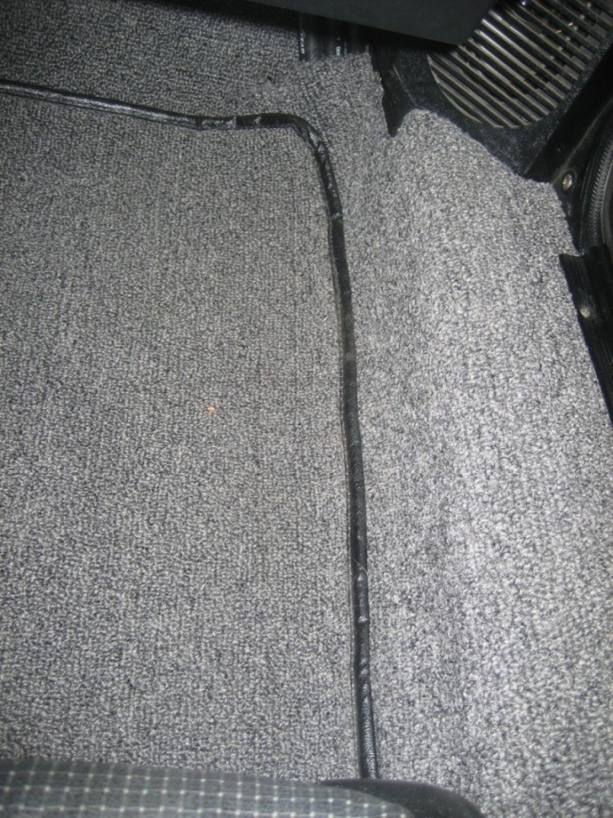
It turned out that the biggest challenge, was routing the refrigerant hoses. The 914 just doesn't give you many favorable options in this regard, so I did some serious head scratching and came up with the following. I really dislike the original 914 dealer installed hose routing where they punch holes through inner fender panels ans such, so I went in another direction. The first decision was to use reduced diameter barrier hose, which as the name implys, its diameter is smaller that the standard hose of the same size. Though the fittings are less common, the smaller diameter hose made the routing much nicer. Starting at the compressor, I routed the -8 pressure and -10 suction hoses through the engine firewall and into the lower right passenger side using bulkhead fittings. The hoses run under the engine shelf, pass through the firewall, then with 90 degree ported fittings, the hoses sweep downward and run along the floor where it meets the long in the cabin. You'll see in the photos how the ported fittings intrude into the cabin behind the seat. To keep the seat from crashing into the fittings, I made some seat stops in the seat rails. I only needed to shorten the seat travel by 7/8", so it is really un-noticable. I painted the fittings flat black, so they go un-noticed (and they're behind the seat anyway). Held in place with Adel clamps, the hoses run forward; the -10 to the evaporator, and the -8 forward through the lower floorboard bulkhead, under the fuel tank, through the front trunk blukhead, and on to the condensor. The -6 high pressure hose runs from the condensor to the drier. The GM refrigerant pressure sensor is attached to one of the un-used drier ports using an adapter. From the drier, the -6 hose parallels the -10 hose under the fuel tank and through the floorboard and to the evaporator. By running the hoses along the floor and long joint, once the carpet is in place, it is completely un-noticable.
Back at the compressor, I had to get a custom compressor block made such that the hoses would point in the most favorable direction; that was a tough one, as there's so little room to route the hoses effectively away from the headers and keep from abrading against the chassis. I also made a heat shield between the header and the compressor.The custom compressor block was made by Doc's Blocks (Stark Mfg), which would make anything custom from your drawing but unfortunately they've changed thier business model and no longer do custom work and sell only through distributors.....This is really too bad, as they were a fantastic resource up until that time....and their prices were great!
For the heat function, I ran two -8 hoses through the passenger side heater duct. I first wrapped them with extra thick electricians tape to help guard against any incidental abrasion. I added 1/2" (-8) x 5/8" adapters on heater core side which made things less tidy than I would have liked, but they're hidden out of sight anyway. The heater (hot water) control valve (HCV) is in the engine compartment. The LS1 heater water flow system logic is such that the HCV is normally open with the engine off (no vauum), but once the motor is started, the vacuum closes the HCV. This requires a different approach to the vacuum switching valve (VSV). You need a VSV that is normally open until heat is requested at which point the VCV closes and vents the NO side which allows the HCV to open. I found a VSV from a Toyota (NAPA P/N: CRB 226873) that had the appropriate logic, so all is good. For a vacuume source, I ran some 1/8" nylon vacuum tubing from the motor to the VSV through the center tunnel, then from the VSV back to the HCV. The nylon tubing is small and easy to route.
As always, please ask.
Attached thumbnail(s)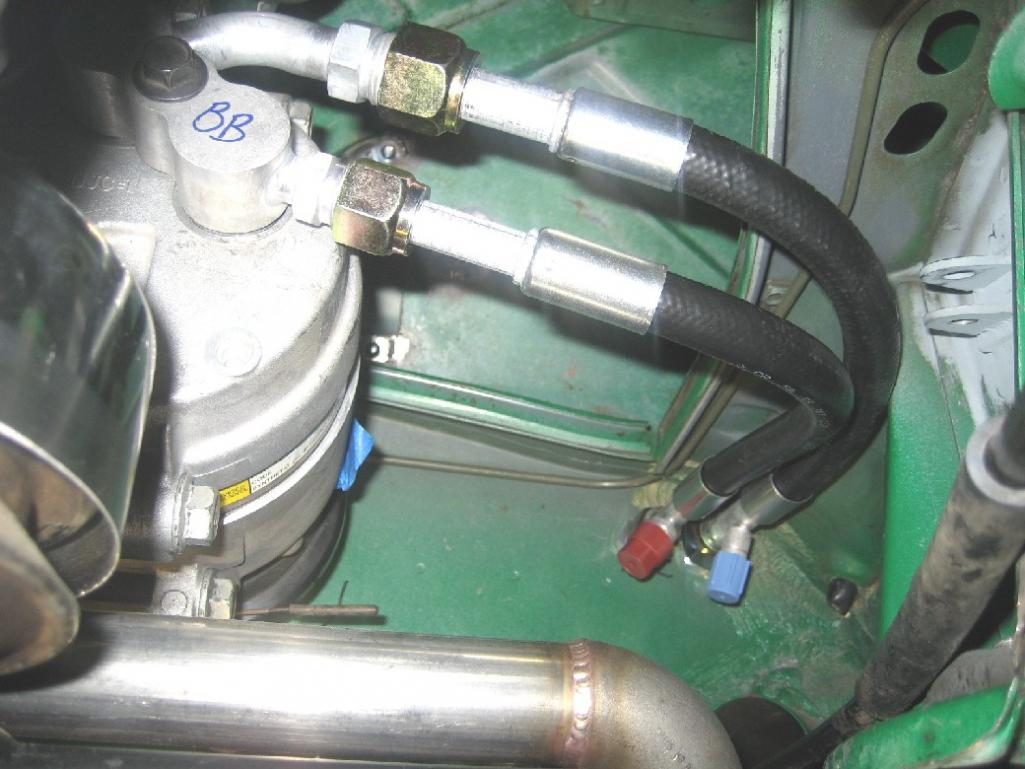

Attached image(s)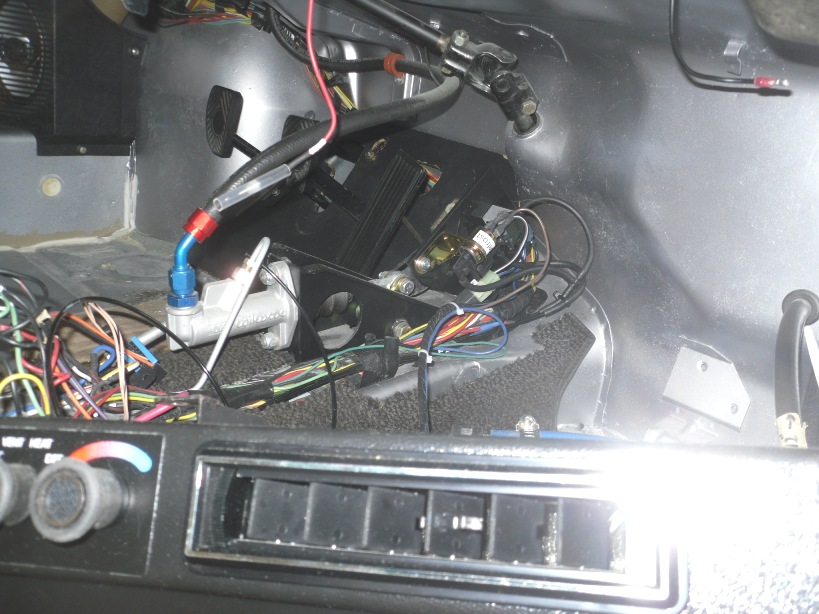
Posted by: drive-ability Oct 7 2013, 11:26 PM
Andy,
That car looks fantastic ! My last (black with the 930 trans) was OK but I
really hope to move up and build a car as you have. Just say the word and I'll drive
up and go for a ride 
P.S. sent you a P.M. through the other forum !
Posted by: andys Oct 8 2013, 01:45 PM
Andy,
That car looks fantastic ! My last (black with the 930 trans) was OK but I
really hope to move up and build a car as you have. Just say the word and I'll drive
up and go for a ride
P.S. sent you a P.M. through the other forum !
Well, you're certainly welcome anytime. The car at the moment, is on jack stands (non mechanical) for easier access to fix the front spoiler that I snagged on the dreaded driveway at the G&R. BTW, I just might go to the next G&R comming up soon. You?
Check you PM's on the other forum.
Andy
Posted by: 914forme Oct 8 2013, 06:35 PM
Okay, I know your not to it in your story but I know its been built.  Do tell about the hydraulic clutch setup!! Just like all the other details it looks like a nice solution to not redoing the footwell area.
![popcorn[1].gif](style_emoticons/default/popcorn[1].gif) I can't wait for more.
I can't wait for more.
Posted by: 914forme Oct 8 2013, 06:35 PM
double post- sorry
Posted by: andys Oct 9 2013, 10:10 AM
Okay, I know your not to it in your story but I know its been built.
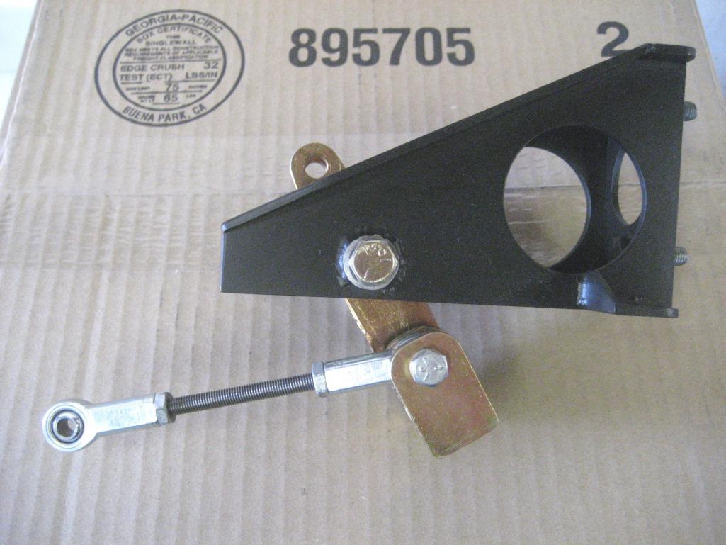
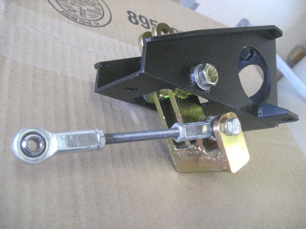
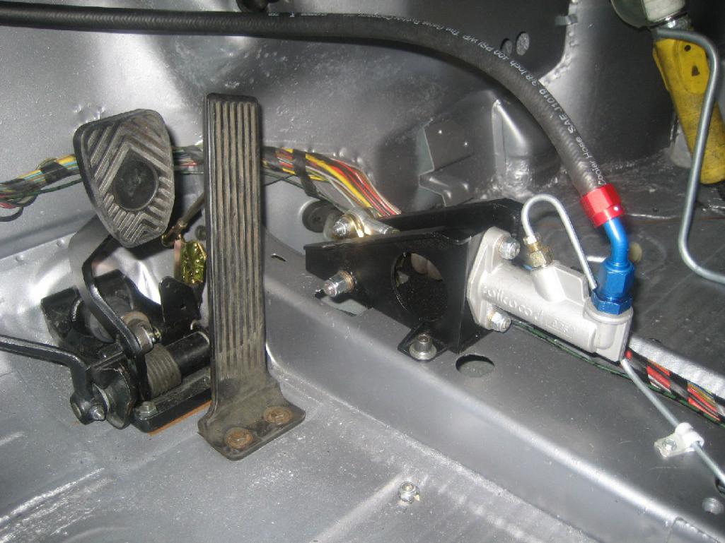
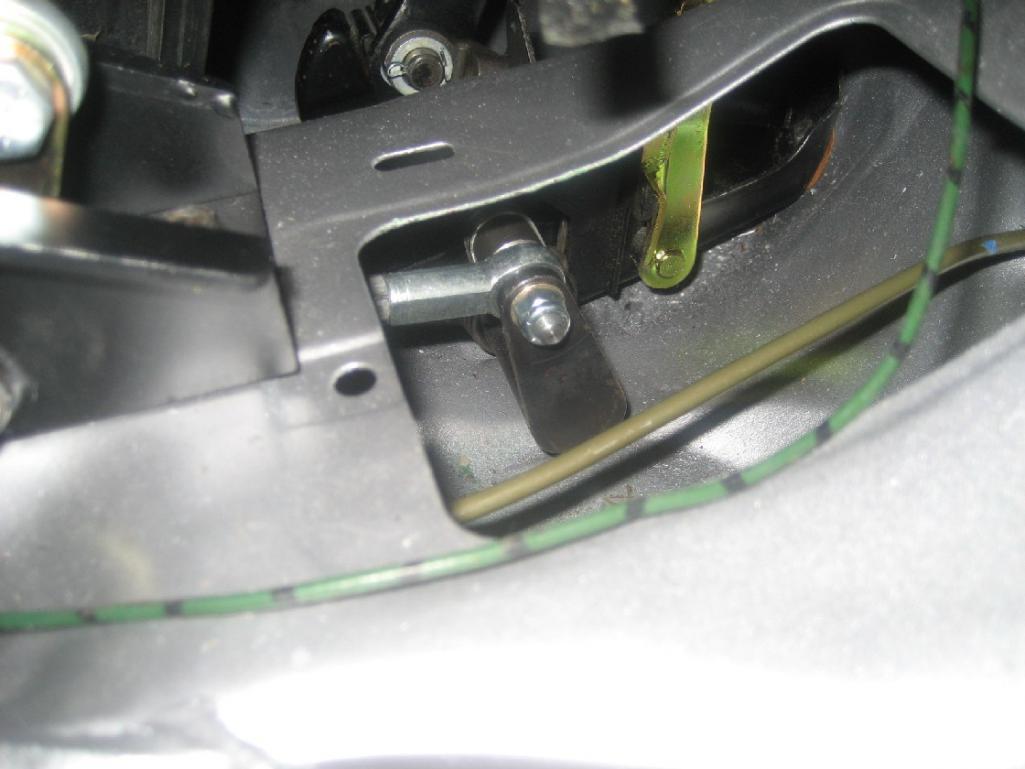
Do tell about the hydraulic clutch setup!! Just like all the other details it looks like a nice solution to not redoing the footwell area. I can't wait for more.Stephan,
I see that I didn't post any detail photos of the hydraulic clutch set up you ask about, so here you go.
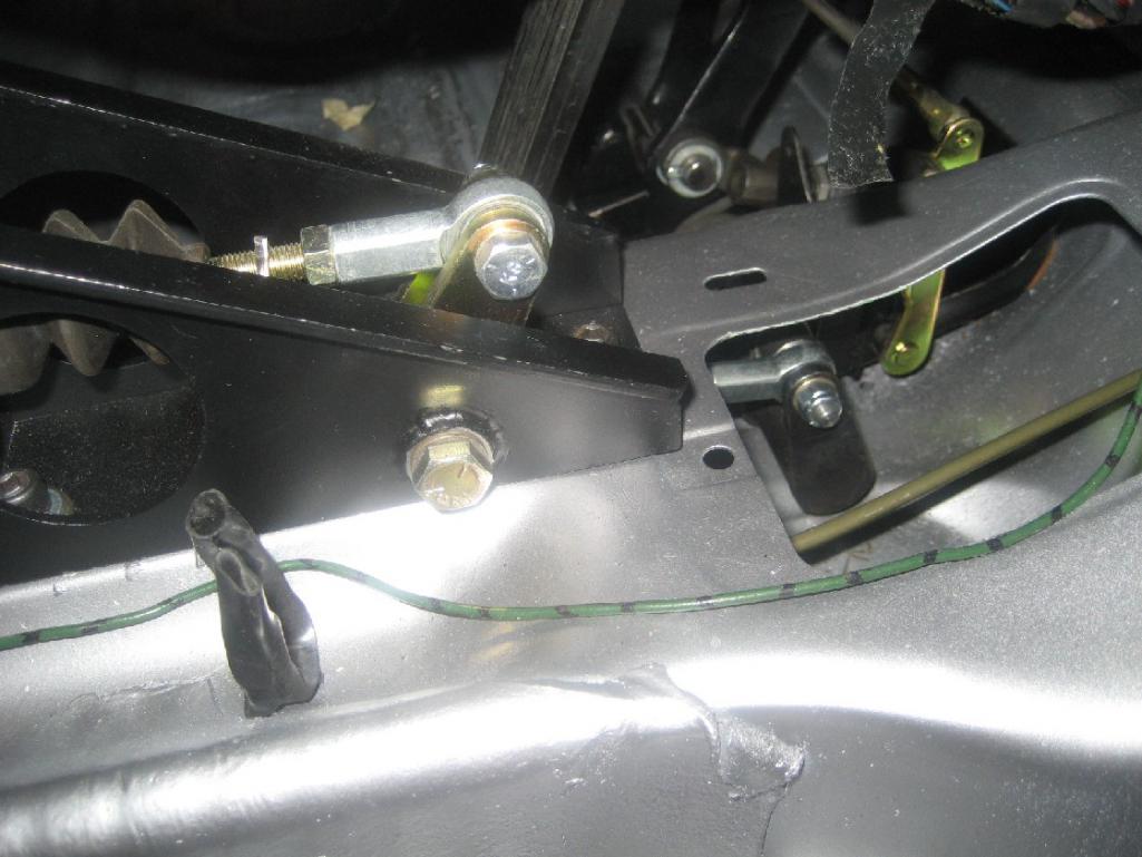
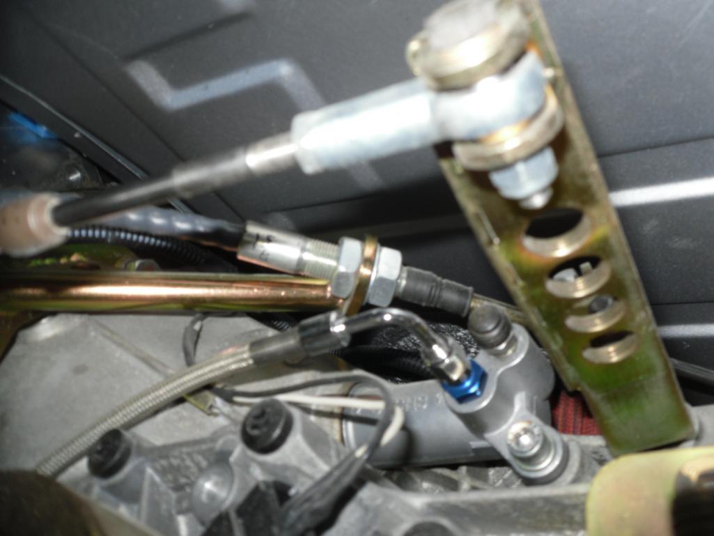
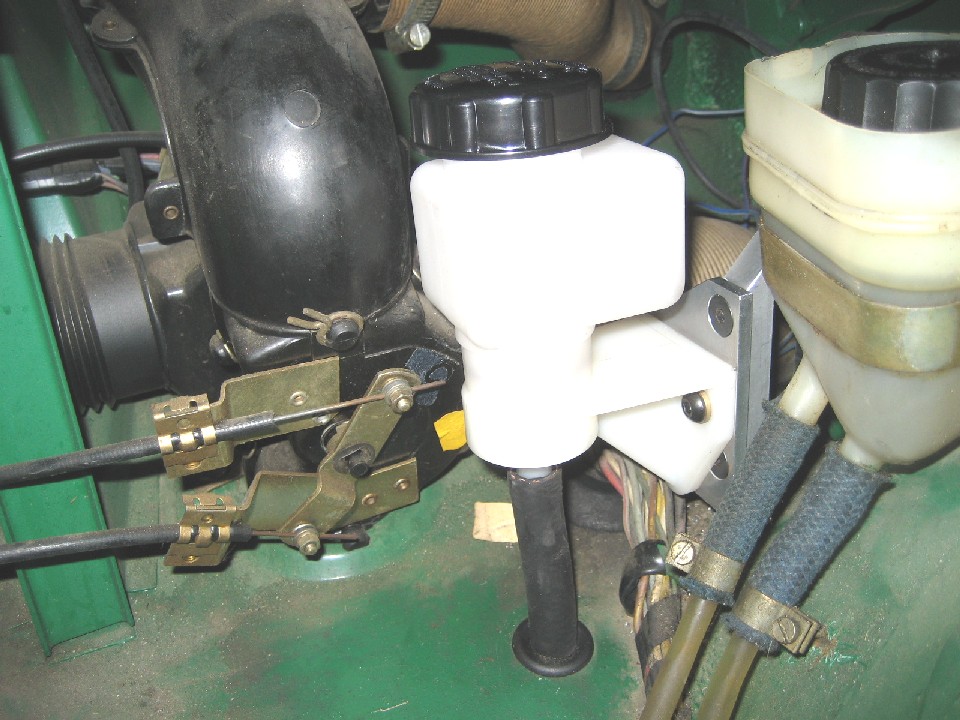
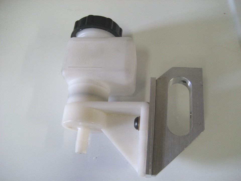
Brief description: I used a 3/4" Wilwood clutch master with a remote reservoir placed next to the brake reservoir. I mounted the clutch master on a bracket with a bellcrank to reverse the throw. The bellcrank has a rod with heim's that couple to the original clutch lever (slightly modified for double shear). I removed the original spiral spring, and replaced it with one from McMaster-Carr that is wound in the reverse direction so that the clutch pedal is now sprung so it returns to the up position. The clutch master (and shifter, etc.) is hidden by the center console. One photo shows the slave on the trans. Please ask if you don't see.
Andys
Attached thumbnail(s)
Attached image(s)
Posted by: 914forme Oct 9 2013, 01:00 PM
Thank you sir that is absolutely brilliant, and I am going to steal your idea, modify it a little to fit my build. Thank you for sharing.
Posted by: Mueller Jan 18 2015, 11:54 AM
wow, just wow....great build...after seeing such innovative ideas and quality parts you made I don't think I'll ever create a build thread!
Posted by: drive-ability Jan 18 2015, 05:17 PM
I want you on my team !!!!!!!!
Posted by: Maltese Falcon Jan 18 2015, 08:42 PM
Just read through your thread with great enthusiasm
Makes me want to work more hours on our conversion.
Like the dude in the movie "Interview", I would say:
All of your 914 v8s are belonging to me !
Hope to meet up with you and your 914 soon
Marty
Posted by: mgp4591 Jan 18 2015, 09:28 PM
Thanks for the link Andy- got me inspired to work on mine almost 3 hours worth after a 12+ hour shift this morning. Got home at 7 am after work, didn't get out of the garage until 10! Mine won't be as pretty but it should work just fine for my wants and needs. Are you signed up for WCR? If so, looking forward to meeting you and this gem of yours. 
Posted by: andys Jan 19 2015, 10:41 AM
Just read through your thread with great enthusiasm
Makes me want to work more hours on our conversion.
Like the dude in the movie "Interview", I would say:
All of your 914 v8s are belonging to me !
Hope to meet up with you and your 914 soon
Marty
Marty,
I nearly drove out to your Hollywood Porsche meet, but something came up at the last minute. When are you going to do another one?
Andys
Posted by: andys Jan 19 2015, 10:47 AM
Thanks for the link Andy- got me inspired to work on mine almost 3 hours worth after a 12+ hour shift this morning. Got home at 7 am after work, didn't get out of the garage until 10! Mine won't be as pretty but it should work just fine for my wants and needs. Are you signed up for WCR? If so, looking forward to meeting you and this gem of yours.
Well, if the build thread inspired you, I'm honored. Not signed up for the WCR. The dates never seem to work out for me.
Andys
Posted by: JRust Jan 19 2015, 11:47 AM
Thanks for the link Andy- got me inspired to work on mine almost 3 hours worth after a 12+ hour shift this morning. Got home at 7 am after work, didn't get out of the garage until 10! Mine won't be as pretty but it should work just fine for my wants and needs. Are you signed up for WCR? If so, looking forward to meeting you and this gem of yours.
Well, if the build thread inspired you, I'm honored. Not signed up for the WCR. The dates never seem to work out for me.
Andys
How about Route 66 in Palm Springs in March? Love to see your car in person too

Posted by: andys Jan 19 2015, 12:17 PM
Thanks for the link Andy- got me inspired to work on mine almost 3 hours worth after a 12+ hour shift this morning. Got home at 7 am after work, didn't get out of the garage until 10! Mine won't be as pretty but it should work just fine for my wants and needs. Are you signed up for WCR? If so, looking forward to meeting you and this gem of yours.
Well, if the build thread inspired you, I'm honored. Not signed up for the WCR. The dates never seem to work out for me.
Andys
How about Route 66 in Palm Springs in March? Love to see your car in person too
Jamie,
Thanks for the heads-up. March is a maybe. Just got a consulting gig that may interfere, but won't know till late Feb./early March. Also, is there some sort of motel uncertainty?
Andys
Posted by: JRust Jan 19 2015, 04:22 PM
Jamie,
Thanks for the heads-up. March is a maybe. Just got a consulting gig that may interfere, but won't know till late Feb./early March. Also, is there some sort of motel uncertainty?
Andys
The Hotel was sold & new owners are taking over. We are good to go though. Reservations called in were held. Not sure about Expedia? It's worth calling to get your reservation to be sure. I just checked on mine & they have it. So should be good to go
Posted by: Mueller Jan 19 2015, 04:39 PM
Are you doing your own plating on the small steel parts or shopping those out?
The neat thing about this build is your selective use of plated parts, it gives it a much closer feel of the parts being OEM.
Posted by: Maltese Falcon Jan 19 2015, 08:40 PM
Just read through your thread with great enthusiasm
Makes me want to work more hours on our conversion.
Like the dude in the movie "Interview", I would say:
All of your 914 v8s are belonging to me !
Hope to meet up with you and your 914 soon
Marty
Marty,
I nearly drove out to your Hollywood Porsche meet, but something came up at the last minute. When are you going to do another one?
Andys
Certainly a Hollywood Cars+Tacos is coming up , just getting lots of non-car things in order now. The gathering would not be the same without Old School...so get strong soon Jaime, and don't miss this one Andy !
Posted by: Rand Jan 19 2015, 09:57 PM
I just hope those who poopoo this conversion find a way to get it.
Nice work.
Posted by: andys Jan 20 2015, 11:04 AM
Are you doing your own plating on the small steel parts or shopping those out?
The neat thing about this build is your selective use of plated parts, it gives it a much closer feel of the parts being OEM.
I sent out all my zinc plating. You can do a lot of small parts for the minimum batch charge. Included in my box full of parts, was a photo of all the parts along and a part count. Thankfully, nothing ever got lost.
Andys
Posted by: drive-ability Mar 26 2015, 11:18 PM
That is one nice car, great craftsmanship bumper to bumper.
NOW DRIVE CAREFULLEY !!!!!!!
Posted by: Mueller Aug 11 2017, 02:58 PM
Anything new to show us on this cool build?
Posted by: andys Aug 11 2017, 03:38 PM
Well, the car is done, but then again, they are never really done-done.
I changed the header tank coolant routing from the hot side to the cold side, which necessitated re-routing some of the coolant lines. Took more work then I expected, but got it done.
The steam vent lines I originally installed are nylon. I did this because the 1/8" diameter tubing lends itself well to the tight spaces they pass thru. I always knew the nylon may be an issue, but took the risk anyway. What's happening, is that I am getting some slight weeping of coolant right at the compression nut, which goes away when I snug up the nut. Over time, the weeping returns, so I will probably re-configure it with small diameter braided hose.
The trans has developed a leak. I'm pretty sure the input shaft seal is the culprit. This repair obviously requires me to drop the engine/trans. Bummer is that I can only do some short drives around town. Think I'll wait till the weather cools a bit before tackling this job. At least it will give me the opportunity to inspect stuff as well as clean-up some of the wiring.
Andys
Posted by: whitetwinturbo Aug 27 2017, 10:33 PM
.........lurking in Newport Beach  and love to see this beauty in person some day
Powered by Invision Power Board (http://www.invisionboard.com)
© Invision Power Services (http://www.invisionpower.com)