Printable Version of Topic
Click here to view this topic in its original format
914World.com _ 914World Garage _ "TRANSZILLA"
Posted by: mrbubblehead Mar 9 2013, 08:15 PM
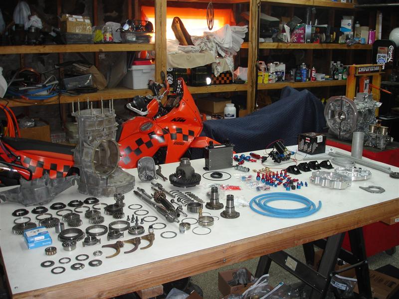
after a couple of months of planning and parts collecting i have finally started my transzilla build. it will using a normal 914 side shift trans, with a few up grades, i will be dialing in the ring and pinion back to spec with this build also.
i laid all the parts out on my assembly table to give you guys an idea of all the parts installed.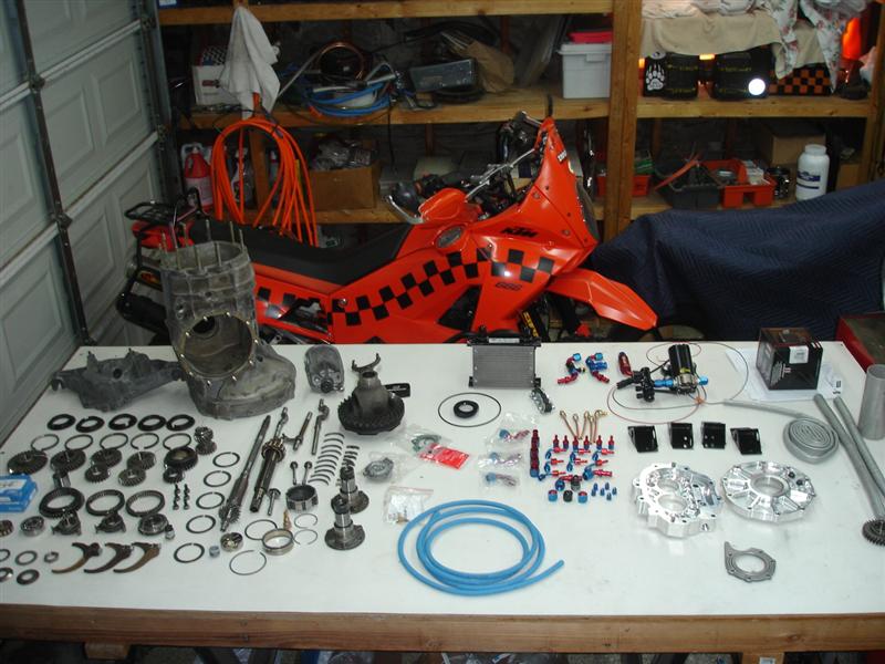
Posted by: turk22 Mar 9 2013, 08:20 PM
scary!

Posted by: mrbubblehead Mar 9 2013, 09:46 PM
a friend suggested i do a build thread after i disassembled and cleaned all the parts. so i will begin starting with assembling the pinion shaft. first thing i had to do is figure out the pinion depth. this is done with a combination of shims. this is when you have to put on your thinking cap and do some math.
after using the formulas in the factory manuals i came up needed 1.38mm of shims. rounded up i would actually install 1.40mm worth of shims.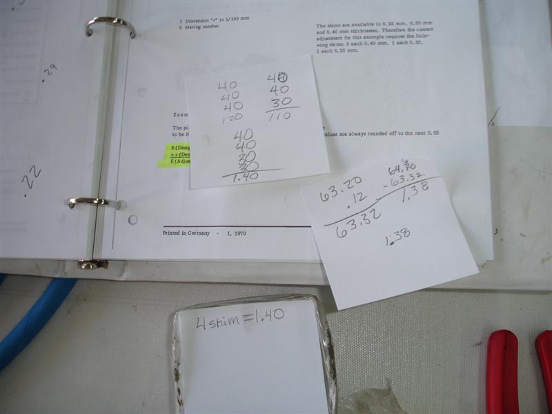
this is where have a big assortment of shims comes in handy.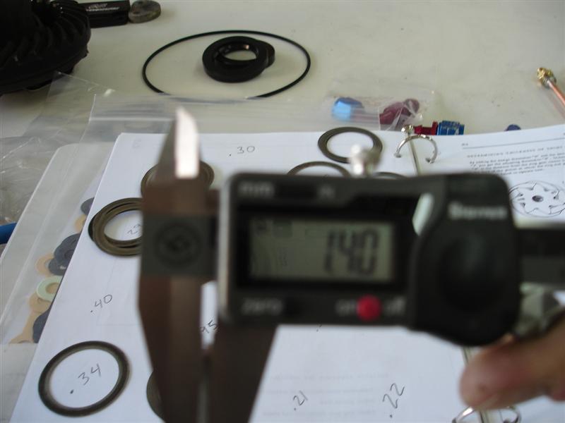
then i dropped them onto the shaft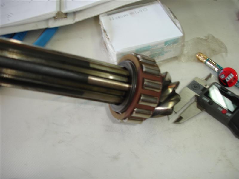
Posted by: mrbubblehead Mar 9 2013, 10:06 PM
then i had to assemble all of the spinning gears. this is done by pressing the dog tooth on to the gear.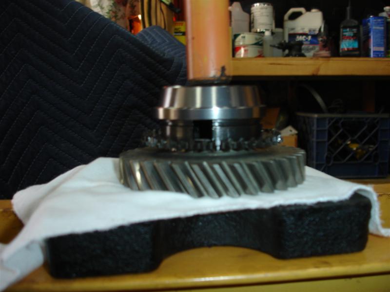
next to go in are the anchor and thrust blocks. the brake bands and the syncro ring.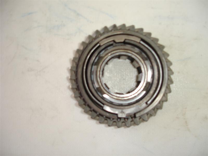
and finally the snap ring. then measure the syncro assembly to see if it falls in the tolerance.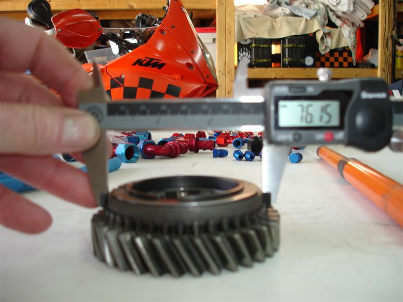
after all five gears are assembled, they are ready to be installed.
one thing i forgot to mention. after i disassembled the gearbox i did an initial check. while everything is still dirty and oily i am looking for anything out of the ordinary. metal chips, broken bearing cages, and setting suspect pieces to the side. then everything got a thorough cleaning and recheck. suspect pieces again were set to the side for further investigation. i have a cool little usb microscope that is attached to my garage computer so i can see the magnification on my computer screen.
Posted by: mrbubblehead Mar 9 2013, 10:42 PM
the rest of the pinion shaft is just like assembling puzzle. when done it should look like this.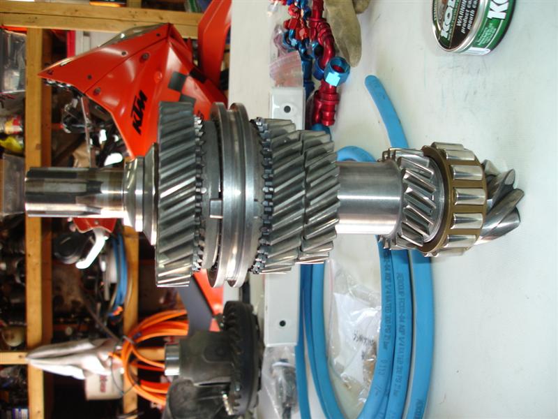
and this is the main shaft. no special math for this shaft. just assembling the puzzle. an interesting note about the 901 gearbox is the second gear fixed gear is actually part of the main shaft so you cant really change the ratio for second gear. i take that back. the are a couple of ways to change its ratio. you can use a 904 main shaft. which has a removable second gear. but its big bucks, if you can even find one. or the second gear can be machined off and the new gear can be welded on.
here is the completed main shaft.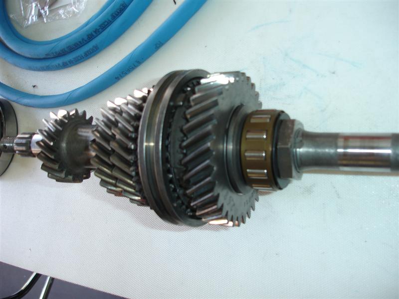
here is my professionally calibrated torque wrench.  its for the big nut that holds the whole shmeer together.
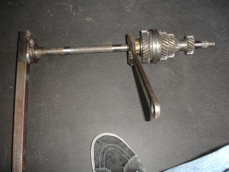
then the washer gets peened over to keep the nut from loosening up.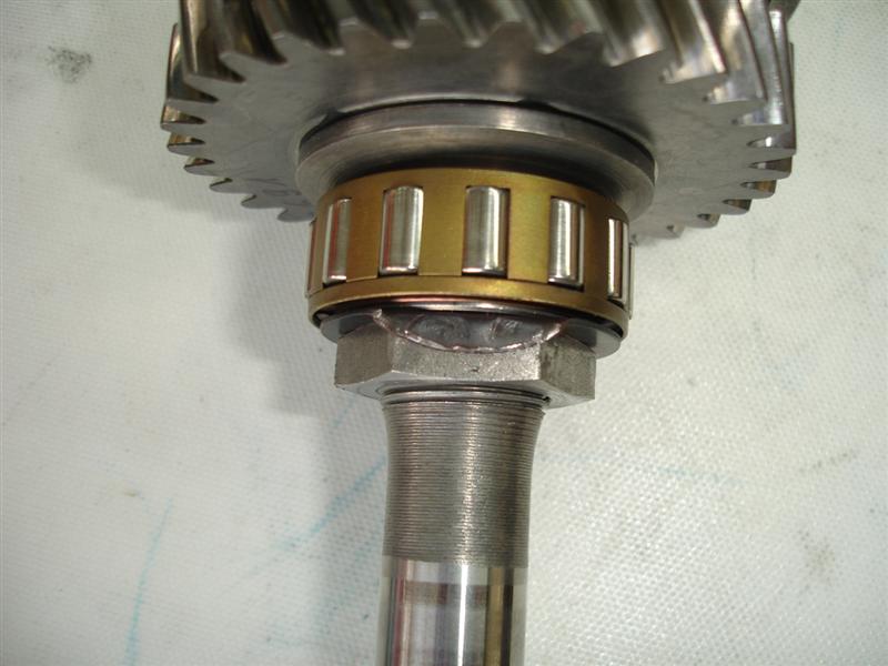
Posted by: dfelz Mar 10 2013, 12:47 AM
GO Doug! Glad you started your thread, project look really good
Posted by: yeahmag Mar 10 2013, 01:09 AM
Nice!
Posted by: mrbubblehead Mar 10 2013, 01:16 AM
thanks guys. i got the boring stuff out of the way. its gonna start getting good from this point on! 
Posted by: Black22 Mar 10 2013, 07:47 AM
![popcorn[1].gif](style_emoticons/default/popcorn[1].gif)
Posted by: 396 Mar 10 2013, 10:06 AM
Brings back memories - good luck with your build
Posted by: mrbubblehead Mar 10 2013, 06:32 PM
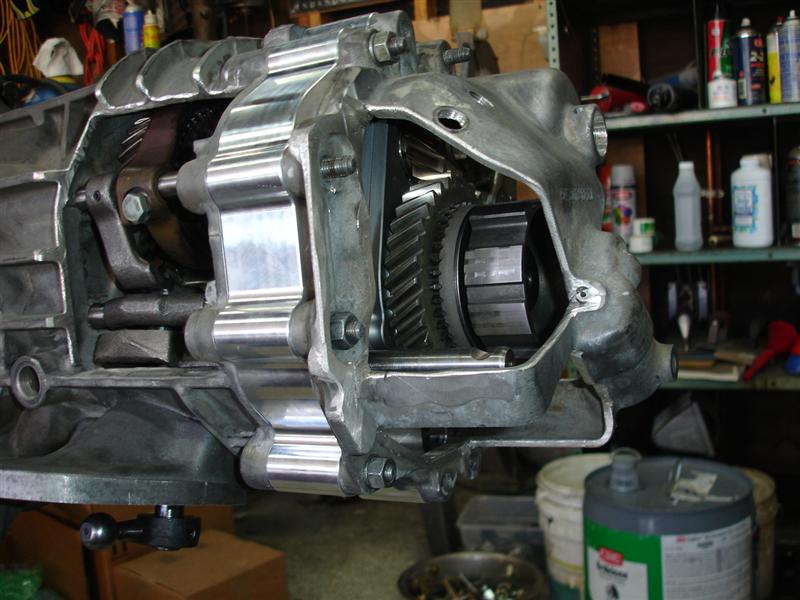
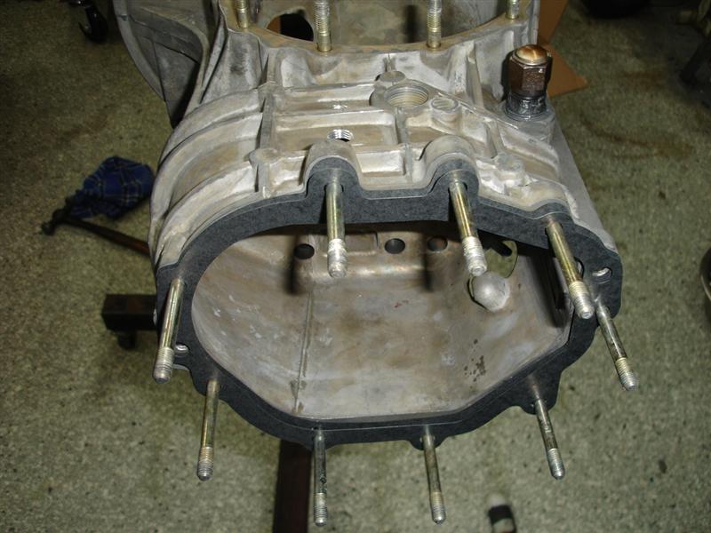
next on the list is to put together the intermediate plate.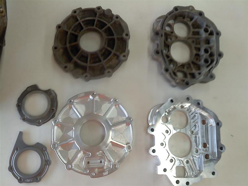
i had to work quickly so i couldnt stop for picture. first thing was to put both bearings in the freezer for 1 hour. then bake the intermediate at 300 degrees for 15 minutes. when the intermediate plate is at a crispy golden brown i pulled it out of the oven grabbed the bearings out of the freezer and gently tapped them in. yes to my pleasant surprise, i had to tap them in. i thought they would just fall in. those bearings are in TIGHT!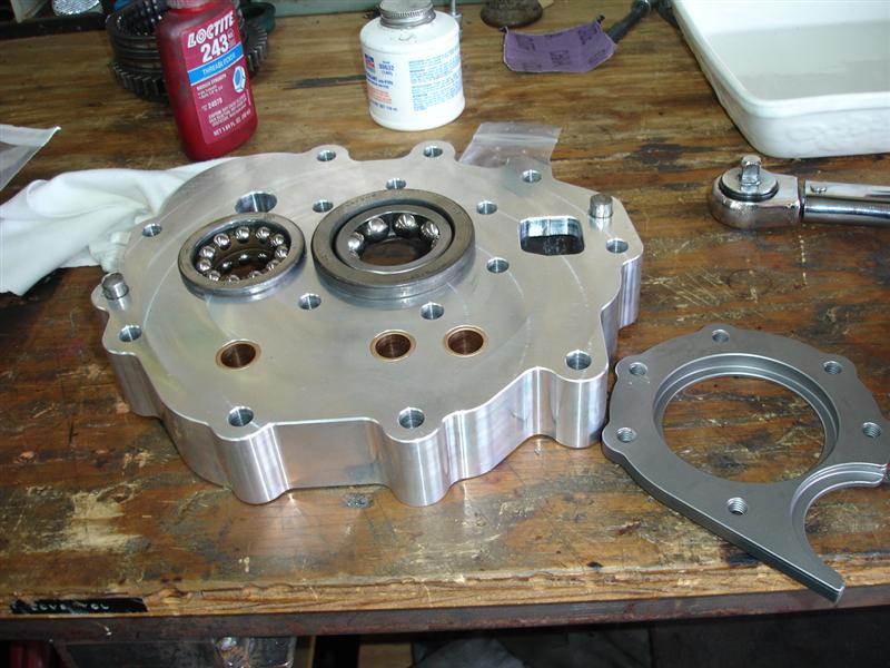
while it cooled i prepped the bearing retainer bolts with a little red lock tight. 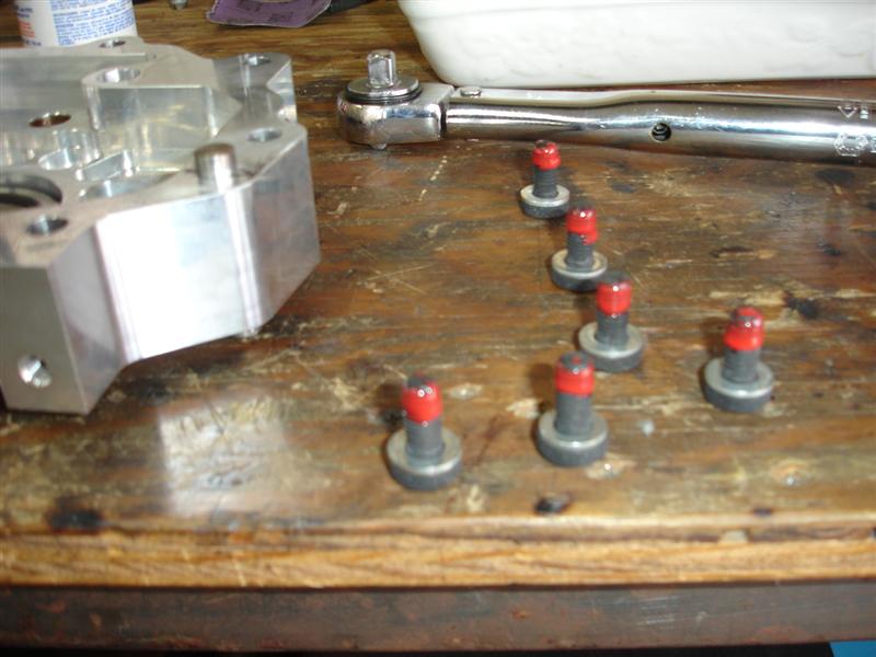
and mounted the chromolly bearing retainer. those bearings are not gonna budge!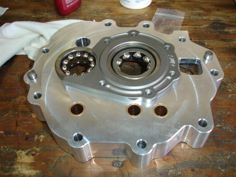
Posted by: mrbubblehead Mar 10 2013, 06:49 PM
its time to install the main shaft and pinion shaft to the intermediate plate. and install both first gears. and the reverse and idler gear, and torque every thing down. again.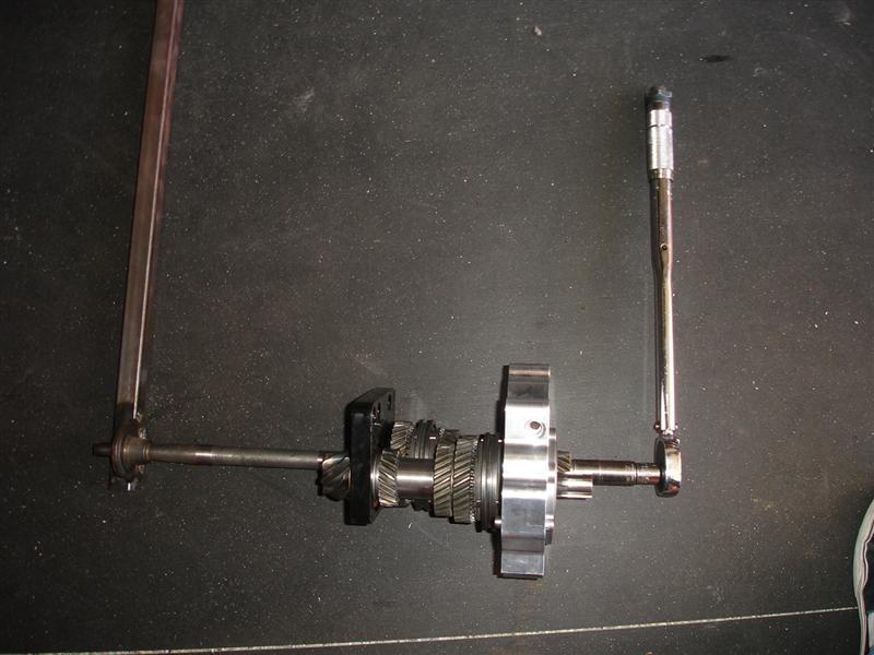
i installed it into the jig and finished the torquing.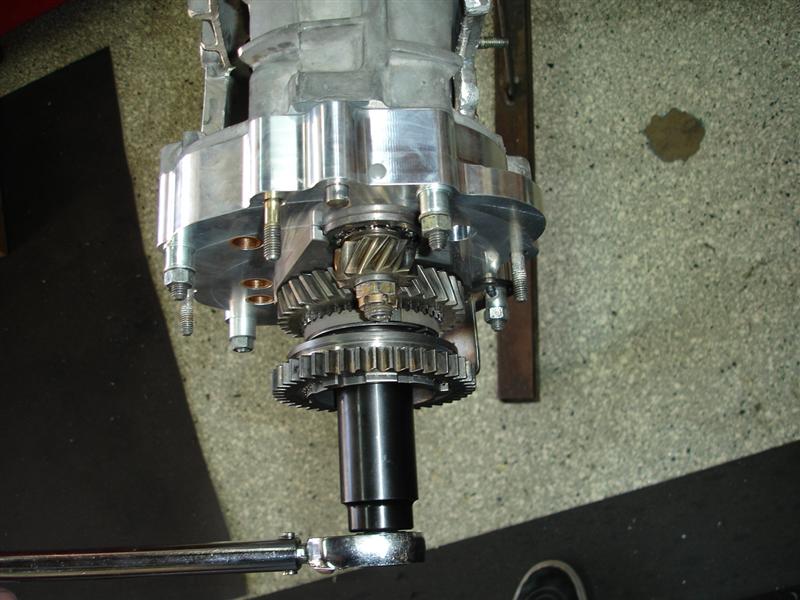
once i was satisfied everything was in its proper order, the now "gear stack" came out of the jig. i installed the detent hardware and shift rods and back into the jig to adjust the shift forks.
Posted by: Richard Casto Mar 12 2013, 09:04 AM

a friend suggested i do a build thread after i disassembled and cleaned all the parts. so i will begin starting with assembling the pinion shaft. first thing i had to do is figure out the pinion depth. this is done with a combination of shims. this is when you have to put on your thinking cap and do some math.
after using the formulas in the factory manuals i came up needed 1.38mm of shims. rounded up i would actually install 1.40mm worth of shims.
You are missing the pinion depth money shot! You didn't show how you measured the actual depth to calculate the shim stack. I am curious, what tool did you use to measure the actual depth?
Nice clean work by the way!
Richard
Posted by: mrbubblehead Mar 12 2013, 11:37 AM
a friend suggested i do a build thread after i disassembled and cleaned all the parts. so i will begin starting with assembling the pinion shaft. first thing i had to do is figure out the pinion depth. this is done with a combination of shims. this is when you have to put on your thinking cap and do some math.
after using the formulas in the factory manuals i came up needed 1.38mm of shims. rounded up i would actually install 1.40mm worth of shims.
You are missing the pinion depth money shot! You didn't show how you measured the actual depth to calculate the shim stack. I am curious, what tool did you use to measure the actual depth?
Nice clean work by the way!
Richard
thank you richard.... i will take a picture of my pinion depth tool for you today and post it up tonight. my next installment is going to be the pinion depth, bearing preload, and back lash. im now sure how many people would actually do these critical steps, so i wasnt going to spend much time on them. i havent even gotten to the good stuff yet (rubbing hands together)
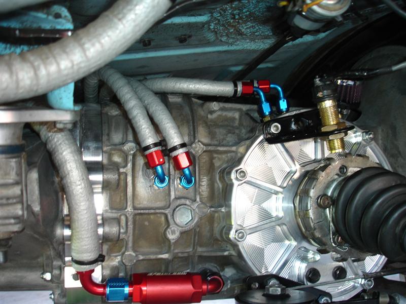
for anyone whos interested heres a preview of whats to come. my oiling circuit pre install mock up and testing. cooler mounting, pump mounting, plumbing etc. double shearing the shift console.
i just buttoned up the gearbox last night and may install either tonight or tomorrow. fingers crossed.
Posted by: Richard Casto Mar 12 2013, 03:18 PM
i will take a picture of my pinion depth tool for you today and post it up tonight. my next installment is going to be the pinion depth, bearing preload, and back lash. im now sure how many people would actually do these critical steps, so i wasnt going to spend much time on them.
I don't think many would (or would have the tools to) do it themselves, but I think they would be curious to see what tools and processes are involved.
Richard
Posted by: 396 Mar 12 2013, 03:24 PM
I will take a picture of my pinion depth tool for you today and post it up tonight. my next installment is going to be the pinion depth, bearing preload, and back lash. im now sure how many people would actually do these critical steps, so i wasnt going to spend much time on them. i havent even gotten to the good stuff yet (rubbing hands together)
for anyone whos interested heres a preview of whats to come. my oiling circuit pre install mock up and testing. cooler mounting, pump mounting, plumbing etc. double shearing the shift console.
YES count us in on these $$$ shots. I'm very interested in the bearing preload / back lash info. I've read up on several treads stating you have have 'special' tools . Then just last night on I read that IF one changes an open ZF for a ZF LSD ...one does not have to really check all these ...reason being all ZF dims are the same.
Thank you

Posted by: Ductech Mar 12 2013, 03:28 PM
He'll I would like to know for that glorious day I track down a LSD in the wild
Posted by: mrbubblehead Mar 12 2013, 03:40 PM
I will take a picture of my pinion depth tool for you today and post it up tonight. my next installment is going to be the pinion depth, bearing preload, and back lash. im now sure how many people would actually do these critical steps, so i wasnt going to spend much time on them. i havent even gotten to the good stuff yet (rubbing hands together)
for anyone whos interested heres a preview of whats to come. my oiling circuit pre install mock up and testing. cooler mounting, pump mounting, plumbing etc. double shearing the shift console.
YES count us in on these $$$ shots. I'm very interested in the bearing preload / back lash info. I've read up on several treads stating you have have 'special' tools . Then just last night on I read that IF one changes an open ZF for a ZF LSD ...one does not have to really check all these ...reason being all ZF dims are the same.
Thank you
Posted by: mrbubblehead Mar 12 2013, 03:41 PM
He'll I would like to know for that glorious day I track down a LSD in the wild
i know right

im ready for it now....

Posted by: Richard Casto Mar 13 2013, 06:55 AM
I'm very interested in the bearing preload / back lash info. I've read up on several treads stating you have have 'special' tools . Then just last night on I read that IF one changes an open ZF for a ZF LSD ...one does not have to really check all these ...reason being all ZF dims are the same.
Thank you
I don't think that is a safe assumption. I am sure suppliers to machine diff related parts all the same. And many are likely very close to spec, or similar enough that you could use the same shims in the new as was in the old. But if all of the suppliers (ZF or otherwise) could machine everything exactly to spec, Porsche wouldn't have designed in the use of shims in various places. And all specs have some (+/-) so even if "to spec", tolerance stacking requires shims anyhow. It's not rocket science to check and adjust backlash/preload. It is more of a time consuming and/or tedious job. You can use commonly available tools plus some parts of your own creation if you don't happen to have the "official" Porsche tools. Many (including myself) don't have the special factory tools. It should be done anytime you swap any differential related parts that impact the total differential and case axial dimension (transmission case, diff cover, diff bearings, ring gear, differential housing)
Richard
Posted by: pcar916 Mar 13 2013, 11:44 AM

Parts are all slightly different from even any one vendor, including the bearing manufacturers. CNC manufacturing helps of course, but don't make assumptions about sizes. The only proof is the final measurement... Then again, you might just be lucky! 
I double-check even when "simply" replacing the carrier bearings when the pinion depth isn't going to change.
Transaxle threads are fun.
Posted by: mrbubblehead Mar 14 2013, 12:45 PM
i'm back, i have been installing and testing transzilla for the last day and a half.... 

i agree with you guys about resetting every thing back to spec. even changing from FAG to SKF has different specs.
richard: i use home made tools also.
here they are top left to right. P37, P259, P357, P258, P259
bottom left to right. P260, back lash torque wrench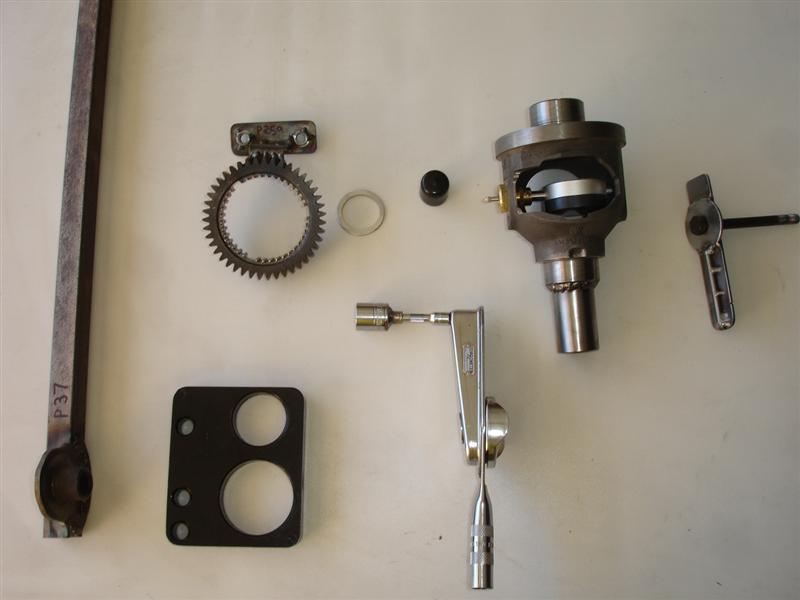
and my favorite BFH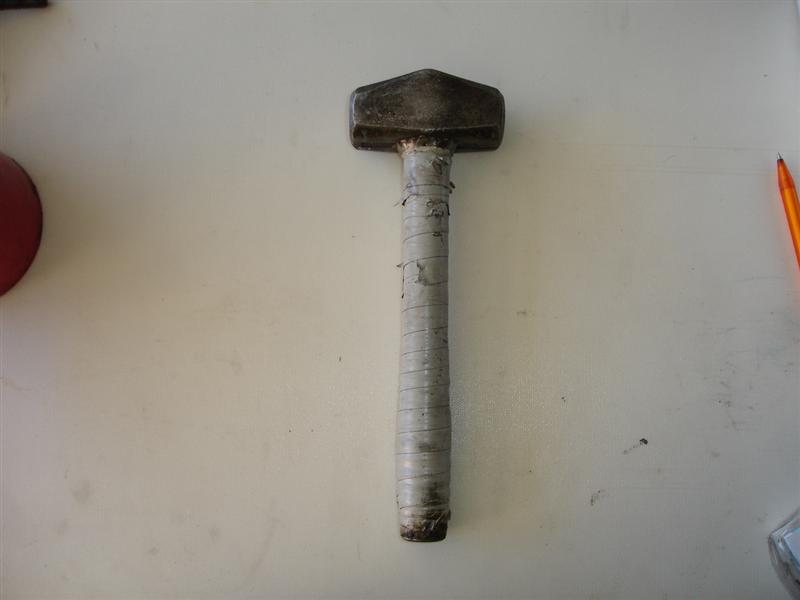
Posted by: mrbubblehead Mar 14 2013, 01:44 PM
i think we left off at measuring the pinion depth. unfortunately, i didnt get alot of pictures but i will post what i have. first i install porsche tool p258, then the gear stack and take the measurement. i know i know more math. then subtract that number from the number in the book. that will give me my gasket(s) thickness between the case and the intermediate plate. pull the gear stack and put the proper thickness gaskets in. dont be fooled. the gasket "kit" comes with three gaskets, but they are all the same thickness. and close dosnt work. i believe they are 0.20mm but porsche offers them in 0.15 and .10mm. you will have to use an assortment of different thicknesses to hit the mark. if you have to use more than .50mm total in gasket thickness you will need to reshim the pinion shaft. and of course the shims are at the bottom of the shaft so the whole shmeer has to come apart to get at them. precision counts. so measure carefully.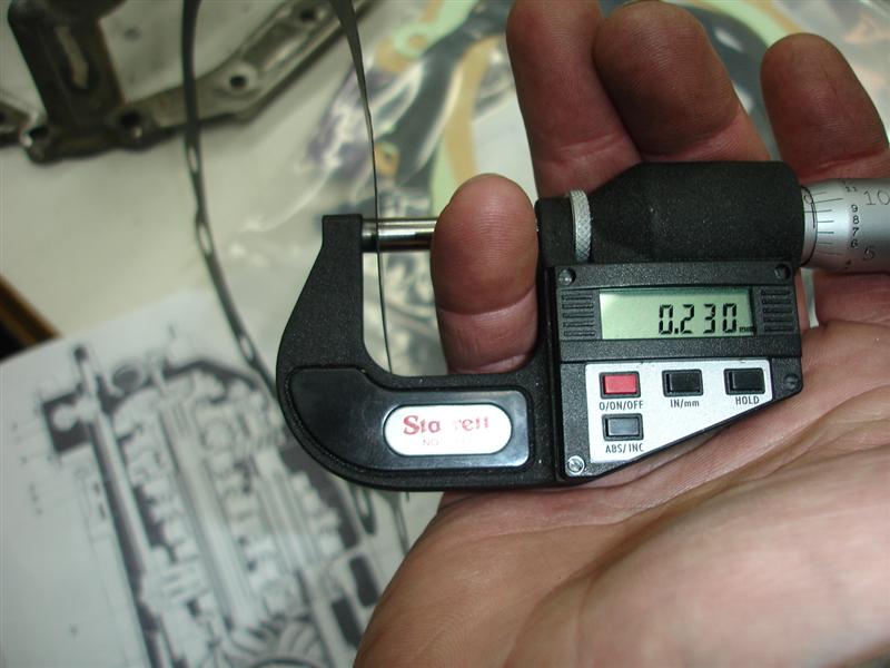
after your gaskets are in place its time to measure again. in with p258 and gear stack. write the measurement down pull the stack and reinstall the stack again. its redundant i know but i like to make sure my measurements are repeatable and accurate. take your measurement and again subtract form your spec measurement. you only have a plus or minus of 0.03mm. mine came out pretty damn close. im satisfied.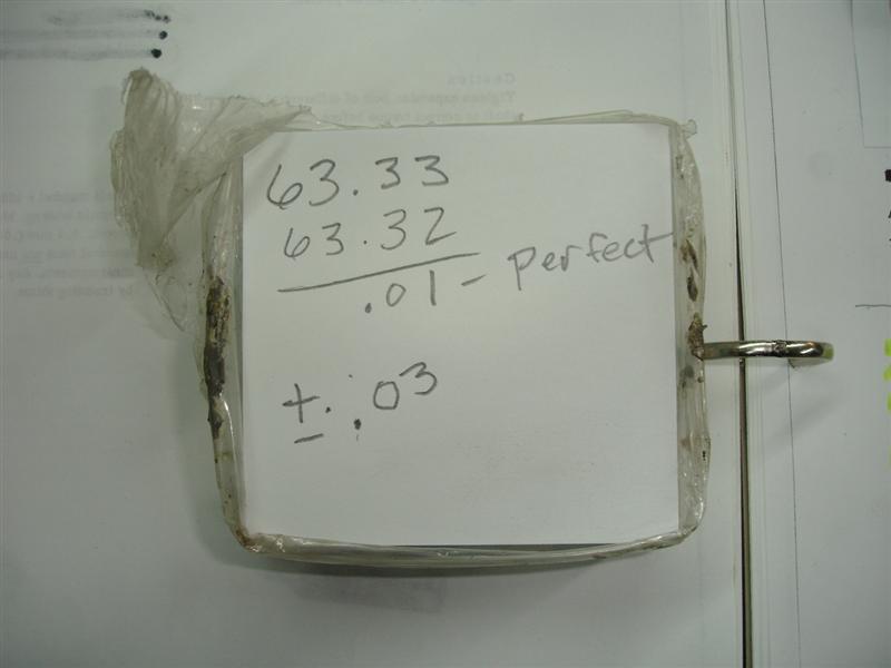
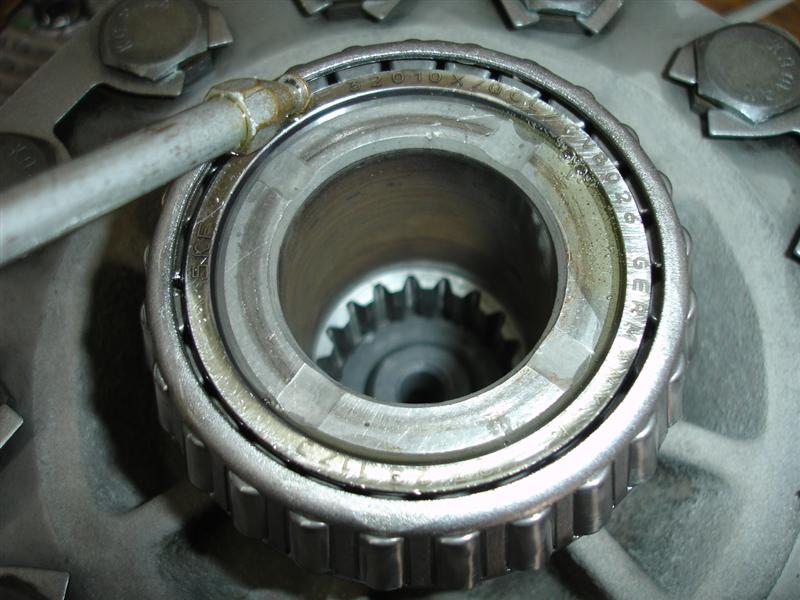
the next measurement to take is bearing preload. again, its good to have a nice assortment of shims. porsche's price per shim? youl'll never guess.... $17.50 PER SHIM!! 
also since i am using skf differential bearings they have a different spec than the fag bearings. i think it is 22-30 inch lbs. after the break away. this measurement is taken with both bearings lubed with gear oil and no seals in the case or side cover. i am using a billit side cover which uses the bigger 930 bearing on the cover side and regular 901 on the ring gear side.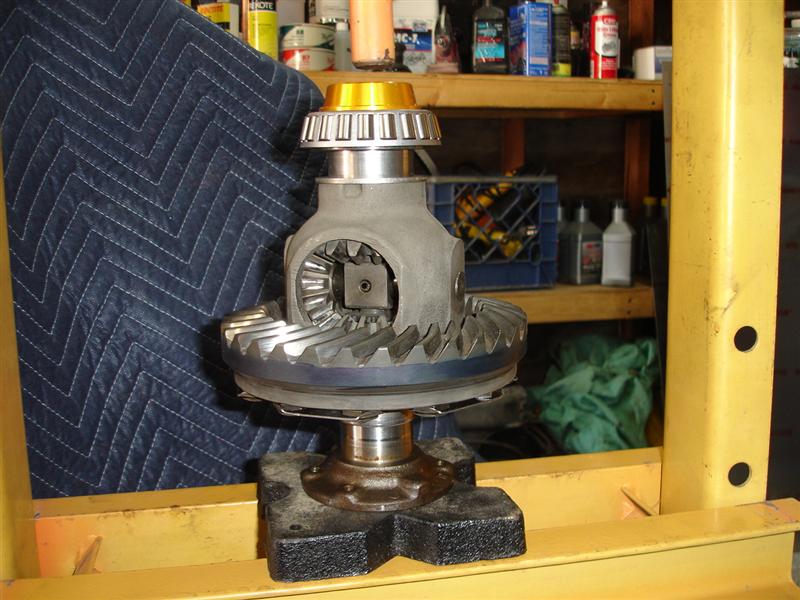
then is a matter of pressing on the bearings, install the dif and side cover, and measuring the preload. ONE WORD OF CAUTION! i never want to use too many shims to start with. to many shims will put the bearings in a bind, and you never want to put them in a bind. i start off thin and sneak up on it, untill im in spec. very very time consumeing.
sorry no pictures of the back lash adjustment, but there is one in the book. essentially what the backlash measurement is to mesh the ring gear to the pinion shaft. not to tight and not to loose (slop). this is a tedious job because you have your total shim thickness from both sides of the diff (preload). now you have to mix those shims to raise or lower the ring gear. it is alot of work pressing bearings off and on, swapping shims, assembling everything, measure, disassemble and do it as many times as necessary. one note. the manual says that the back lash spec is stamped on the side of the ring gear. i have yet to see this number stamped on a 914 ring gear. i have talk to 2 what i consider expert porsche gearbox builders and both told me the same spec. so thats the one i go with. it is a very minute amount of backlash with a very tight tolerance 0.03mm. again very very time consuming. and i make sure all my measurements are repeatable so i always have that extra step.
WHEW! questions so far?
next will be case prep.
Posted by: 396 Mar 14 2013, 03:07 PM
Thanks for the written & visual education....it looks as though I should out source my LSD install
Oh I see your going to install a trans cool too....very nice.
Posted by: mrbubblehead Mar 14 2013, 03:56 PM
Thanks for the written & visual education....it looks as though I should out source my LSD install
Oh I see your going to install a trans cool too....very nice.
i would say yes on the lsd install. its quite an investment for tools, and time. and if your only doing one trans, its probly better to farm it out. but vet your builder carefully. ask to see his tools. there are too many builders out there who just wing it. guessing or taking shortcuts will trash your diff, or pinion shaft in short order. as you can see there is a lot of time involved, so it wont be cheap.
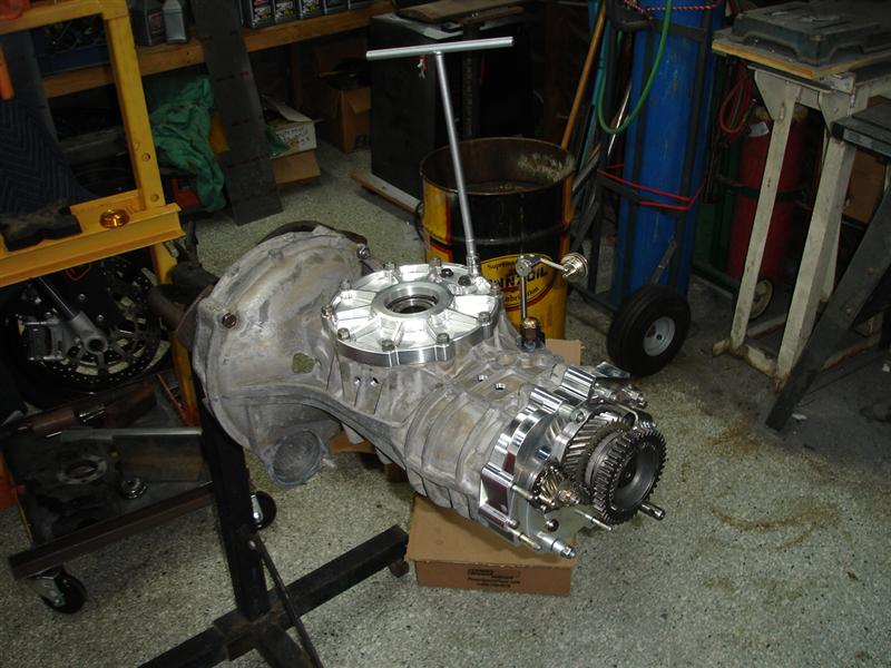
heres a sneak peak at transzilla installed.
Posted by: 396 Mar 14 2013, 05:25 PM
Thanks for the written & visual education....it looks as though I should out source my LSD install
Oh I see your going to install a trans cool too....very nice.
i would say yes on the lsd install. its quite an investment for tools, and time. and if your only doing one trans, its probly better to farm it out. but vet your builder carefully. ask to see his tools. there are too many builders out there who just wing it. guessing or taking shortcuts will trash your diff, or pinion shaft in short order. as you can see there is a lot of time involved, so it wont be cheap.
heres a sneak peak at transzilla installed.
Very nice
Is that a speed sensor I see on the cv?Posted by: mrbubblehead Mar 14 2013, 05:36 PM
yes, its for my electronic speedo.
Posted by: Dr Evil Mar 14 2013, 06:31 PM
I love it 
I agree that I have never had a new LSD or even a factory one that needed shim changes. BUT, I still check all the parameters because I dont want to miss one. Besides, I do mail order and the last thing I want is to have to do a fix on a rightfully pissed off customers tranz. Measure twice, cut once
Posted by: Dr Evil Mar 14 2013, 06:40 PM
A note, your adjusting of a used R&P does lend itself to close enough. I know for a fact that you do not need to be as precise as the initial build specs when putting a used R&P together. The stock kit works just fine. Also, being off from the stock numbers, even with a new R&P will only lead to noise and not much else unless you are significantly off. It will not destroy your R&P. The factory tech would get them mathematically set, then run them on a special jig and adjust for best noise reduction. That is the number on the pinion head.
Other differentials are set using dye-kem (sp?) or other gear marking paste and then checking the location of the wear patterns. Our tranzaxle makes a more easily detectable song than most vehicles so this extra precision is warranted at first (when new). ALL old R&P will make noise. That noise tends to sound a lot like all other differentials, but is easy to detect in the cabin. Maintaining pinion depth close to stock, which is what I recommend, is a good way to set it as quiet as reasonable without using special and expensive tools. Lots of cost, no real gain.
Posted by: Drums66 Mar 14 2013, 07:45 PM
....You do fine, clean work(I'm impressed)
maybe do some clinic's  (CALI)

Posted by: dfelz Mar 14 2013, 10:37 PM
Looks great Doug, can really tell you have put a SHIT ton of work into this build, but we all know its going to turn out great, good job man!
Not super importnat to the task you are trying to accomplish with these add-ons, BUT are you planning on keeping the clutch cable stock? or throw in a hydraulic line with a MC and slave???....
Posted by: '73-914kid Mar 14 2013, 11:20 PM
Oh no!!!!!! Its Tranzirra ...AHHHRRRRR!!
Awesome writeup man. I know for a fact that my pinion depth is not set correctly, as there is definite backlash problems (Severe) and it whines like a super charger in 4th and 5th with good bearings. Something to take care of at a later date I guess. It hasn't galled the R&P after 25k miles, so I doubt it ever will.
I can't wait to see your car once everything is all done.. It's turned into a monster 914...haha
Posted by: mrbubblehead Mar 14 2013, 11:30 PM
Looks great Doug, can really tell you have put a SHIT ton of work into this build, but we all know its going to turn out great, good job man!
Not super importnat to the task you are trying to accomplish with these add-ons, BUT are you planning on keeping the clutch cable stock? or throw in a hydraulic line with a MC and slave???....
no plans for a hydraulic clutch david. i carry a spare cable with me. i have converted a few bajas to hydraulic clutches, but its a lot of work. to much work for not so much gain. hanging pedals would be cool though
im thinking about coming up with a cable shifter design.i have done just about everything i can with mine, brass shift coupler bushings, tangerine racing firewall bearing, double shear console. next i will either go to sealed u joints or cable shifter.
all my new gauges came in so my new dash will be next. should i do a write up on the new dash too?
Posted by: mrbubblehead Mar 14 2013, 11:35 PM
Oh no!!!!!! Its Tranzirra ...AHHHRRRRR!!
Awesome writeup man. I know for a fact that my pinion depth is not set correctly, as there is definite backlash problems (Severe) and it whines like a super charger in 4th and 5th with good bearings. Something to take care of at a later date I guess. It hasn't galled the R&P after 25k miles, so I doubt it ever will.
I can't wait to see your car once everything is all done.. It's turned into a monster 914...haha
a properly set up diff is soooooo smooth and quiet.
Posted by: dfelz Mar 14 2013, 11:40 PM
all my new gauges came in so my new dash will be next. should i do a write up on the new dash too?
HAHA, yes! I think you should just document everything your do to your sexy little olympic blue 914, your craftsmanship is fantastic and everyone could learn a lot from your projects (big or small)!
I'll talk to you later through another form of communication about your hydraulic clutch experiences (dont want to hijack this amazing thread)
Posted by: mrbubblehead Mar 15 2013, 08:32 AM
i had mentioned earlier transzilla is going to be oil cooled. so i needed to figure out what should get oil and where. after tons of research and studying the gearbox i came up with this determination. most of the gearbox internals are located in contact with or below the oil level. but their are a few areas that are "splash" lubricated only, the front main shaft bearing, the 4/5 gear slider- sychro rings- dog teeth assembly,and the rear main shaft bearing. i also want to also get cool oil on the ring gear.so i need 5 squirters. i will show you where i located them in more detail later.
the oiling circuit will be something like this....the drain plug will be turned into the supply for the circuit. from the drain plug to a scavenge filter thru an oil cooler thru an electric gear driven pump to a 5 port manifold then to the squirters inside the trans.
first i had to build a custom manifold. the inlet side of the manifold will be -8 (1/2 inch) and the 5 outlet ports will be -4 (1/4)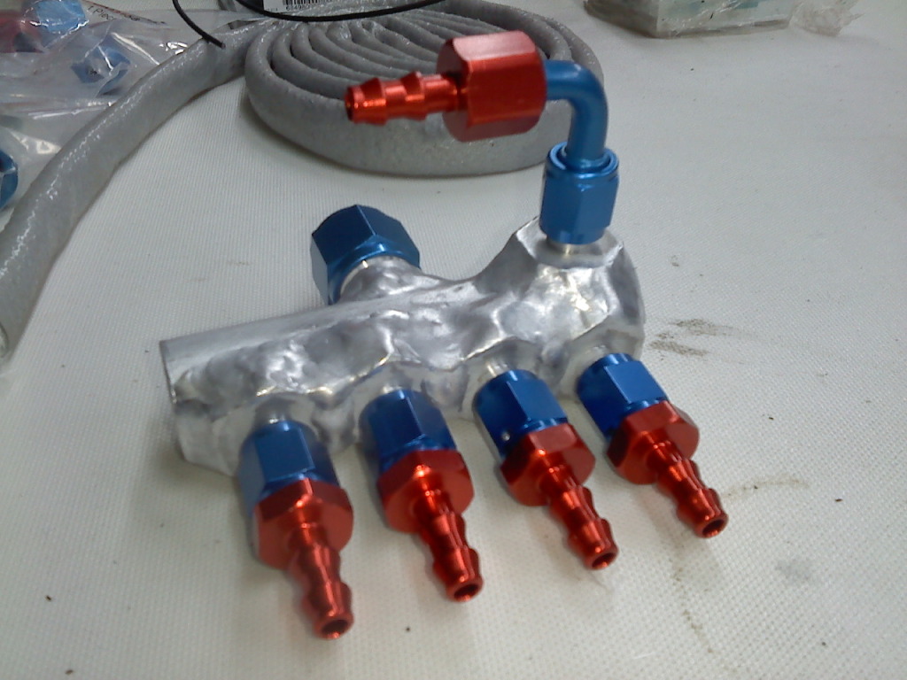
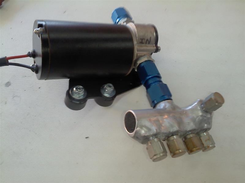
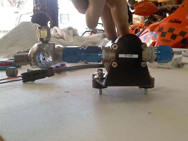
and due to space constraints and to reduce the number of fittings, i attached the manifold directly to the pump. i made a brace to make the tie the two together so they will both benefit from the rubber isolators. 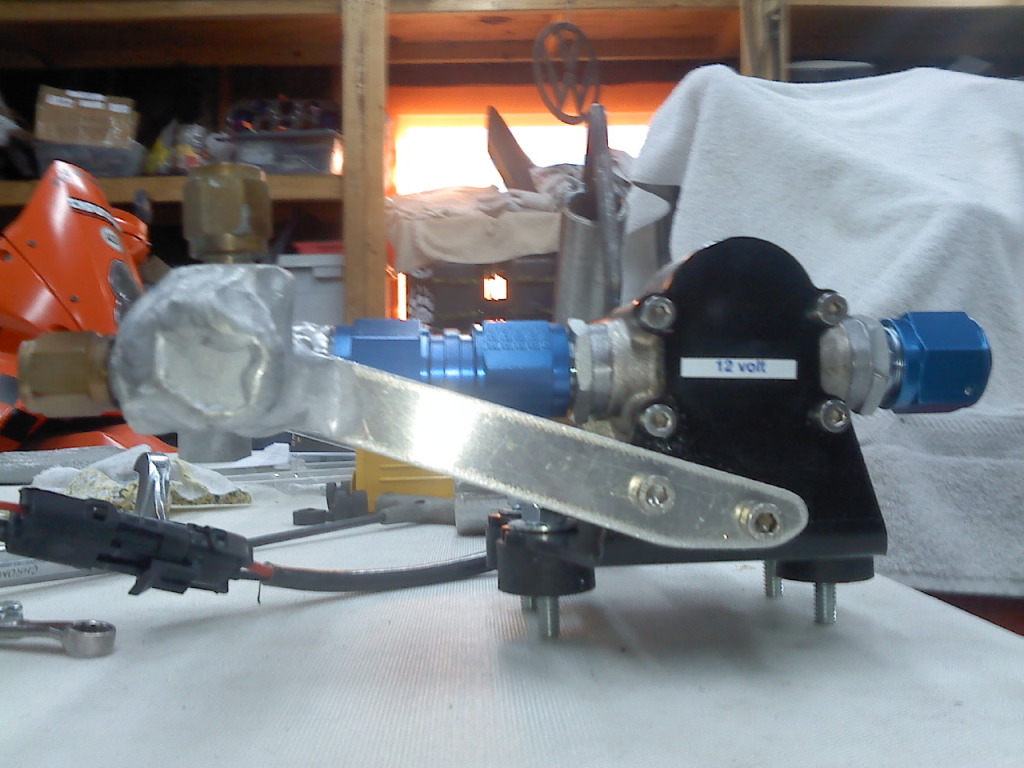
and then i powder coated the manifold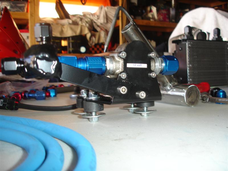
Posted by: mrbubblehead Mar 15 2013, 08:45 AM
the oil cooler needed a little prep work before i use it. because it will be in the rear trunk area, next to my engine oil cooler, i needed to make a stone guard for it. 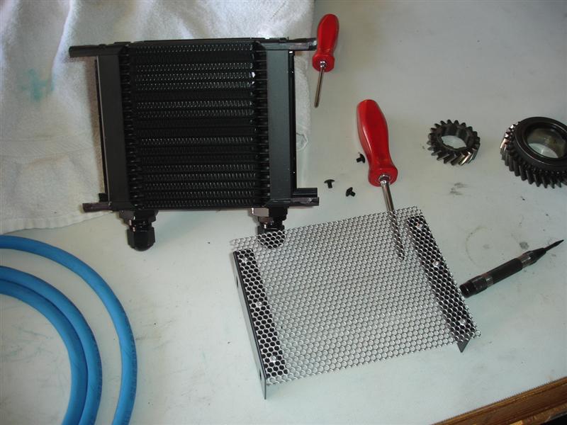
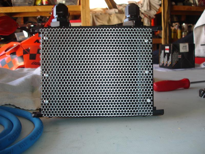
adding the fittings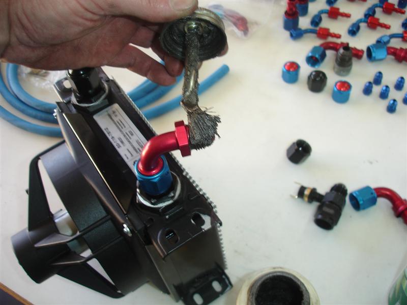
the thermostat switch to turn the fan on.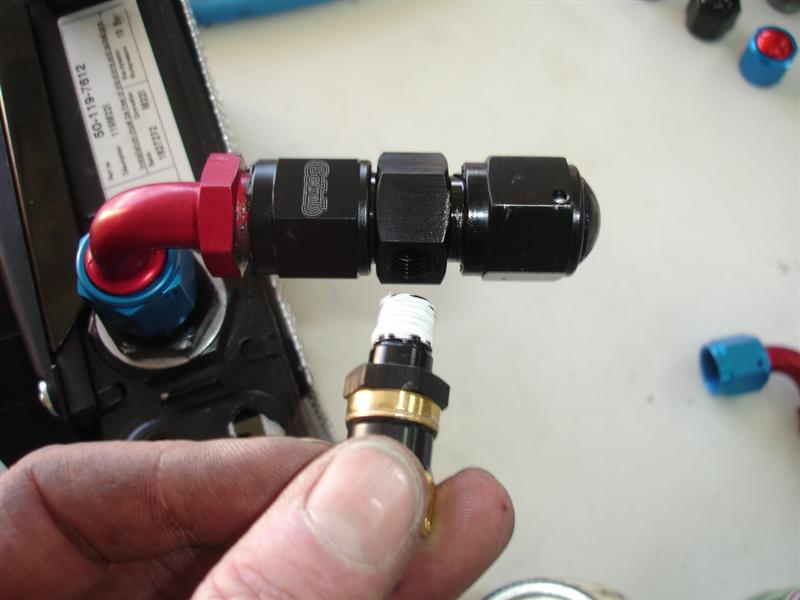
then wired up the fan.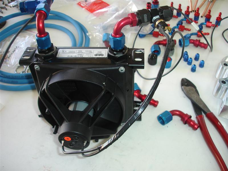
Posted by: Richard Casto Mar 15 2013, 08:52 AM
Hey, awesome stuff. If you are OK with it, I am going to toss in some other info for others who might use this as a guide in the future. I don't think I am saying anything counter to what you are doing.
bottom left to right. P260, back lash torque wrench
For those that don't recognize it, P258 is commonly created from a used differential housing. I think the early smaller housing tend to be the best for creating this tool. It is used to measure the distance between the axis of rotation of the differential to the tip of the pinion shaft.
One tip for newbies, make sure you have good preload on the diff bearings that you use for this tool. If the clamping force from the differential cover it is not relatively tight, you will have inconsistent and non-reproducible pinion depth measurements. So when you measure the depth using P258, check it a few times after rotating the tool to make sure it is consistent and reproducible. If you can push against the shaft while you measure and it makes a difference, you are seeing the bearing move around and the preload is not tight enough.
I have found that the gaskets in the Elring Klinger kits to be the same as you say. I have also found that because after doing a number of rebuilds you have extra gaskets (you don't always need the three they provide) and that there is slight variances in them. So I was able to measure, and sort and sometimes create more ideal matches when I needed to use multiple gaskets. It would be nice if there was an easy source for the old style thicknesses. The old ones used to be color coded and/or had watermarks that indicated the thickness. Regardless, always measure your gaskets to verify thickness.
One tip for newbies who do their own backlash measurement. You really have to make sure you are measuring the correct backlash. With the differential cover on, you are measuring a movement you can't directly see. You have to make sure all the correct things are locked down, otherwise, you might end up measuring the slop between the flange splines and the splines inside the differential or the backlash between the pinion and main shaft. You have to lock down the pinion shaft and make sure the flange is tight to the differential carrier. Then the only movement should be between the ring and pinion.
You also mentioned earlier about measuring preload (via rotational resistance) without the flange seals in place. In case it isn't obvious to others as to why it is done that way, you want to measure just the drag of the bearings and not the bearings plus the drag from the seal.
I know there is a "homemade tools" thread elsewhere. It would be funny to start a "favorite hammer" thread. I have two. One big and one small.
Richard
Posted by: 396 Mar 15 2013, 09:06 AM
Richard, great info. Too much for me digest for one job.
Good education though.
Thanks
Posted by: mrbubblehead Mar 15 2013, 09:06 AM
now for testing. because i dont have a lot of fluid dynamic experience i needed to see how my calculation worked out. i wanted to put it all together and bench test it. once it is installed in the trans i wont be able to see what its doing so i needed a good visual and take some load measurements.
heres the setup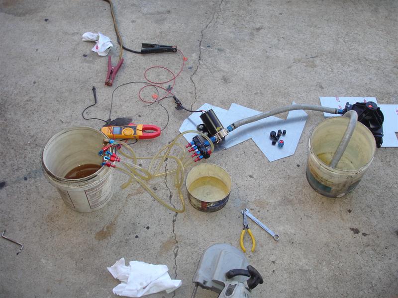
the inrush current is 9.5 amps and the run current was right at 8 amps.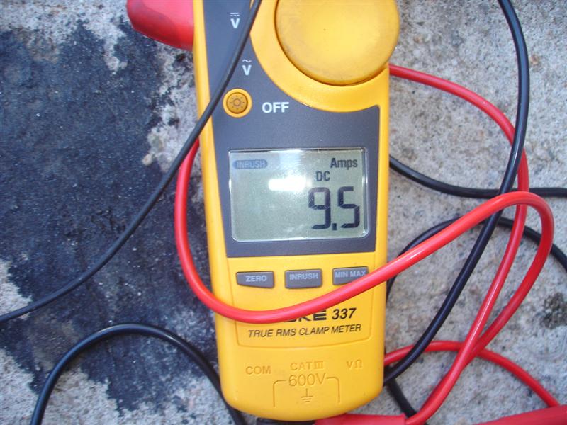
i needed to see the difference in spray patterns. this is the flow for a rounded pattern.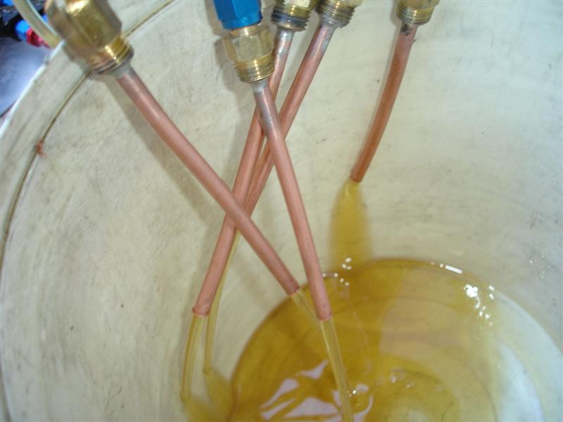
and this is for a more of a fan type spray.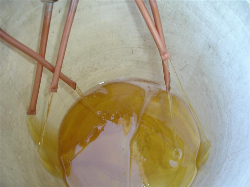
i decided to go with the cut off rounded style for a couple of reasons. because i want more oil flow and dont really need it to shoot any distance.
i want to flood the areas with cool oil to absorb as much heat as possible. and with the crimped fan like pattern the pump pulled two more run amps. since the pump will be on when ever the ignition key is on (via a relay) i want any unnecessary load on the pump so it have a long life.
Posted by: mrbubblehead Mar 15 2013, 09:21 AM
thanks for the input richard. i am a learning mofo so if you see something f-ed up please let me know. i was trying to stay away from making this a how to tutorial intentionally . im sure i have forgotten some steps and would hate for someone to try to reset via this thread and ruin something. a true how to would be boring to most and very long. but i sure appreciate your input. i may not be the best at explaining what is happening. its in my head, but putting it into words is not easy for me. just ask the guys who attended my carb clinic  . what a disaster.
Posted by: mrbubblehead Mar 15 2013, 10:00 AM
if anyone has any questions on anything jump in and ask..... this is my thread and anything goes. so if we need to go back a few pages to answer a question it would be no problem
lets continue. now that i know the oil system is going to work its time to do the case mods.
i have a friend who is a lube oil and analysis engineer and he has taught me alot. i am a firm believer in neodymium magnets. i use them in my engines and gearboxes. they will pick up metal particles down to one angstrom. way smaller than any filter could pick up. so the first thing i do is scuff the bottom of the trans with 80 grit sandpaper and jbweld a long neo magnet to the bottom of the trans.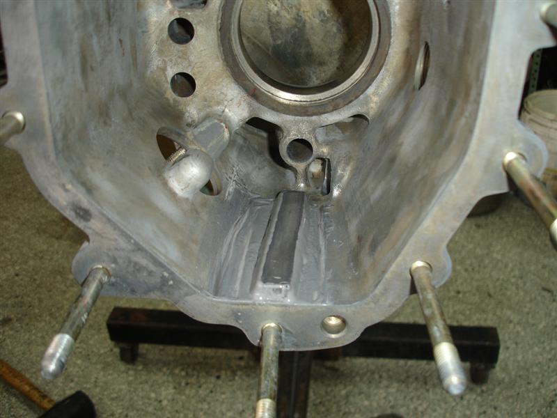
its time to drill and tap some holes for the squirters. these two are for the 4/5 synchro rings and dog teeth. one squirter for each.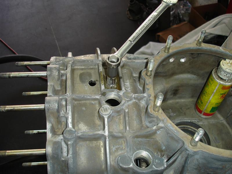
obviously the tubes will be cut down and the tubes bent to supply the oil where needed.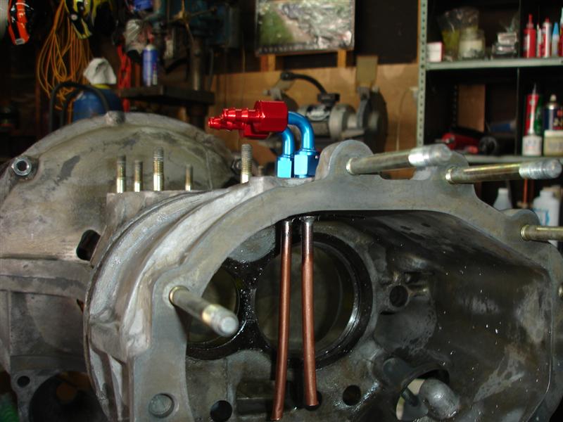
these two holes are for the differential area. one squirter for the front main shaft bearing, and one for the ring gear.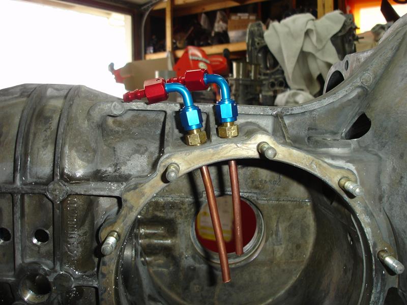

now this picture is just a mock up for the ring gear squirter. in the 914/901 the ring gear rotates clockwise. so i want to squirt the ring right AFTER it meet the pinion to get maximum cool oil on the gear.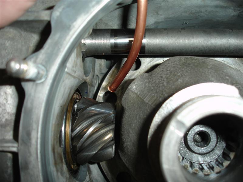
and then i modified an old filler plug (no tiny magnet) to adapt to an AN fitting. this will be used in the original oil drain location. now it is the scavenge exit to feed the pump.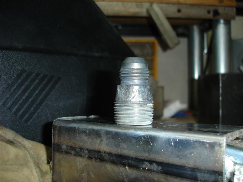
and since the drain plug will never need to be removed again, and wont impede any future cleaning. it gets jb welded in....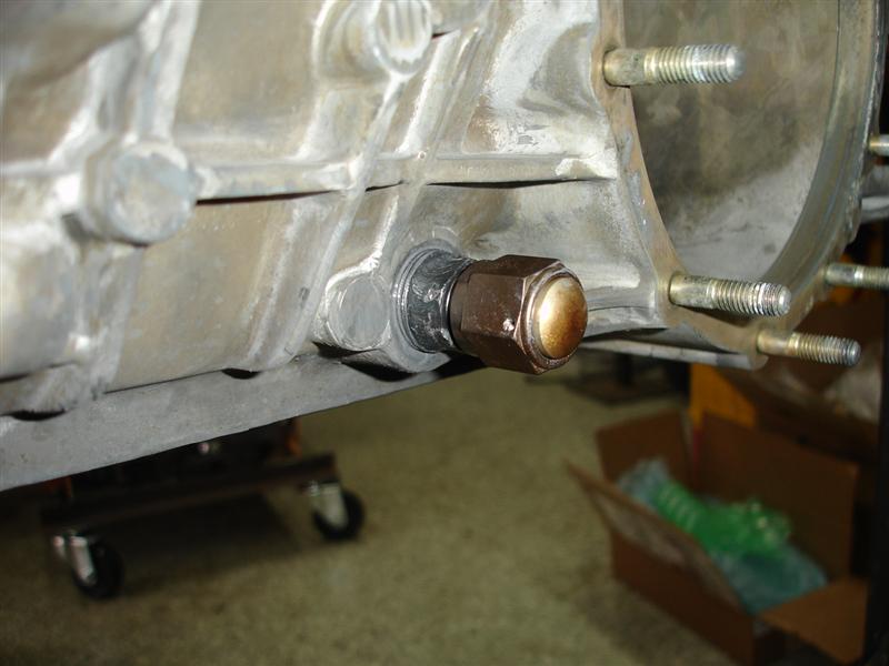
Posted by: 396 Mar 15 2013, 01:53 PM
Very slick set up! If you had this 10 years ago, I would have paid you for one.
Posted by: mrbubblehead Mar 15 2013, 02:56 PM
Very slick set up! If you had this 10 years ago, I would have paid you for one.
thank you for the kind words peter, when your ready to do your 915 let me know...
Posted by: Dr Evil Mar 15 2013, 03:29 PM
So fricken SWEET! I cant wait to hear how it all works. That manifold is this shit!
Posted by: mrbubblehead Mar 16 2013, 11:06 PM
thanks dr. e. the tranny is doing real good. that H gear is a little too long. im not real sure what im gonna do about it yet. i think the HB is shorter right? but can it be flipped? or is it part of the main shaft? i guess my only other option would be an HA. but im not real sure if it will make that big of a difference. a 300 dollar difference. right now at 80 mph i am at 3100 rpm. and of course my cht's went up also. im kinda wishing i had just kept the stock 5th gear in there now because i could bomb up the grades.
anyways, more of the build tomorrow.
Posted by: dfelz Mar 16 2013, 11:32 PM
i dont have a lot of fluid dynamic experience i needed to see how my calculation worked out.
hehe, Doug, bench test looks good to me!!
and i have taken fluid dynamics, two sections of it and the lab! your hands on experiment matches with the theory too, smaller atmospheric exit diameter creates a larger exit pressure, requiring more load on the pump, all the while ejecting the fluid a larger distance from the exit tube. Good job Doug, test successful! What kind of preliminary calculations did you do?? were you basing the system on a specified cycle time of your liking to calculate the rest (flow rate)?
Love this thread man, looks awesome, and very informative for those of us who dont know much about the internals of the trannys, even what they look like....
Besides the HB gear you have in there (which you may switch) are all the other gears stock sizes?
Posted by: mrbubblehead Mar 17 2013, 12:12 AM
thanks david.... my preliminary calculations were actually pretty easy. i took a good guess. i noticed that peterson fluid systems sells a turbo scavenge manifold that has one -8 (1/2 inch) exit with four -4 (1/4 inch) pick ups. and most of the other turbo scavenge manifolds were pretty much the same. but i didnt like the designs or the price. they were crazy expensive. over 200 bucks. mine was like 30 bucks to make. anyways, i was using mine in reverse. feeding oil to, not scavenging from. the manufactured manifold looked like i might have cavitation problems since i was feed oil. this is all seat of the pants mind you. i figured they must have calculated the 4 into 1 to be sufficient. and since i need flow and not pressure i thought adding one more exit would give me that. that was the reason for testing. i just wasnt sure. and i would have never really known without testing out in the open.
as far as the gearing. i have the flipped H gear in there right now. and its a little too tall i believe. the HB is the next step down from the H, and the HA is the next step down from the HB. but at 300 bucks a set, this testing could get costly.
just for reference i have stock 1-4 gears and a flipped H for 5th. stock 15 inch wheels with 205 50 15 tires, with a massaged 1.8 liter pushing it. 5th gear on the freeway was a real screamer with a stock 5th. i was looking for a little less rpm on the freeway with my never ending quest for better mpg. well i ended up with an overdrive. its not toooo bad. i went up the cajon pass in 5th gear no problem but had to drop into 4th because my cyl head temps hit 400 degrees. who knows, maybe i could go above 400 and not worry about it but i would rather be safe than sorry. on flat ground its perfect. its just the damn hills...
Posted by: Dr Evil Mar 17 2013, 03:07 PM
I would not recommend a flipped H for a stock motor, as you see why.
HB is shorter, HA is stuck to the shaft. Just go ZA, save money and be happy. The engines are made to rev, not like a water cooled engine.
Posted by: Cupomeat Mar 17 2013, 03:19 PM
This is a fantastic thread. Years ago before I made the Dr. Evil video, I considered transmission work to be dark arts, but now I would consider doing something like this and I am really impressed with your work here. FANTASTIC!!!
Hey, maybe this is a dumb question, but how do you check/verify fluid level on a transmission setup like this?
Do you just check at the normal fill hole, when the pump is off, or when running?
Truly, I am just curious as it lead to complexity of fluid levels.
Posted by: Dr Evil Mar 17 2013, 07:26 PM
The same as usual, from the fill hole. As long as the system is all primed, you can check at the fill hole bottom ridge.
Posted by: monkeyboy Mar 18 2013, 09:48 AM
I would figure you would fill it the first time, run the pump for a minute so the lines fill up, and then check and top off at the drain hole.
Sound good?
Posted by: PFM Sep 16 2013, 10:54 PM
Doug,
Thanks so much for the link from PP this is a GREAT build. I do have a question regarding squirter locations. For the R&P you picked out of mesh to apply oil for max cooling. A friend and drive line engineer suggested going into mesh to ensure oil film was available during max load. My 901 needs to deal with about 250 LB/FT of TQ. I agree for max cooling with the location but I am more concerned with load. Your input is what I seek. I am also very concerned with the axial load on the intermediate plate bearing from the pinion shaft, max load from pinion forces. You did not add a squirter for either bearing on that end. Any reason why not?
As several have said GREAT thread and information.
Stay Tuned!
PFM
Powered by Invision Power Board (http://www.invisionboard.com)
© Invision Power Services (http://www.invisionpower.com)