Printable Version of Topic
Click here to view this topic in its original format
914World.com _ 914World Garage _ 914RS4 Tube Chassis 996 Suspension Audi 2.7TT Stage 3
Posted by: Curbandgutter Mar 25 2013, 01:12 PM
Well the dream begins. I'm embarking on the building of a 914 project. Here is the candidate. Bought a roller from LA area. Looks like its not going to be too much rust. Firsts thing will be to strip it. Taking front fenders and rear quarters off. Then sending to Cal Blast for media blasting. I look forward to the knowledge that I can gain from fellow enthusiasts. Plan on taking a lot of pics Stay tuned......
DISCLAIMER: Do not attempt to duplicate anything that is mentioned or illustrated in the entirety of this thread. I do not make any warranties of any kind. If you try to build what I am doing, you take full risk. Do not try this. It may be dangerous to your health and may get you killed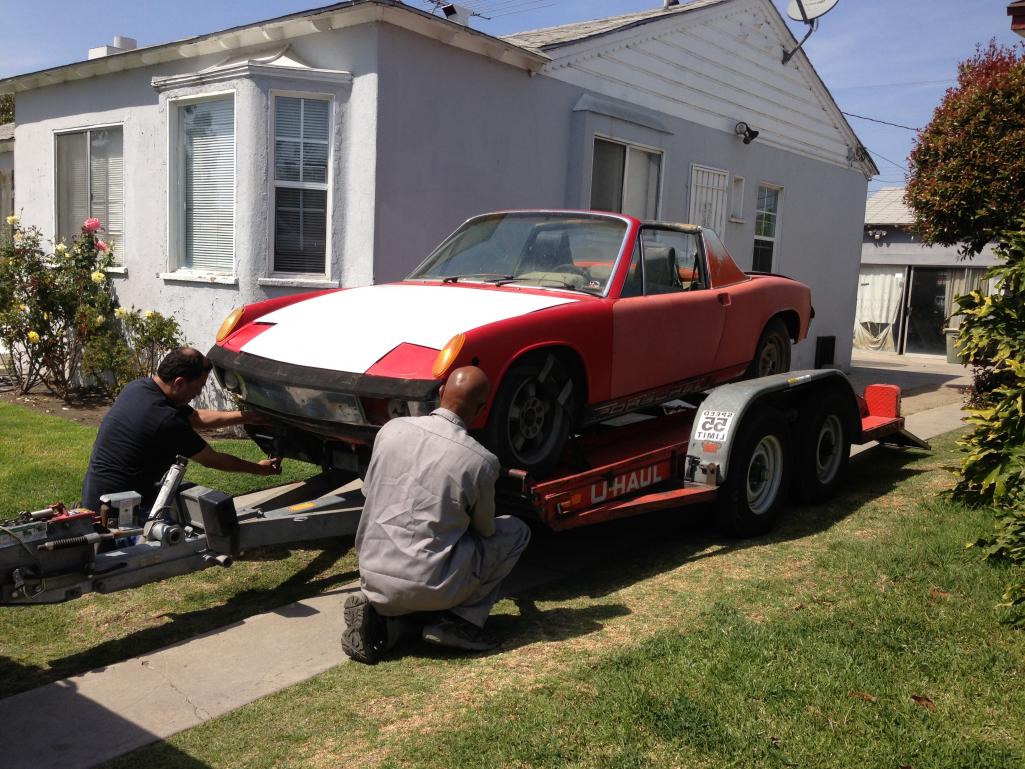
Posted by: kg6dxn Mar 25 2013, 07:07 PM

Posted by: BMiller Mar 25 2013, 08:00 PM
Welcome aboard! 
Posted by: pcar916 Mar 25 2013, 08:26 PM
Good luck!
Posted by: KaptKaos Mar 25 2013, 09:14 PM
Cool!! Where are you in SoCal?
Posted by: Elliot Cannon Mar 25 2013, 10:15 PM
Come to the G&R swap meet. Lots of stuff there you will absolutely need. Forget the roll cage. (Unsafe in a street car). Go with the Sheridan body. 
Posted by: rpmmaxxed Mar 26 2013, 02:02 AM

Come to the G&R swap meet. Lots of stuff there you will absolutely need. Forget the roll cage. (Unsafe in a street car). Go with the Sheridan body.
Just out of curiosity, why would a cage be unsafe in a street car?
Posted by: carr914 Mar 26 2013, 05:25 AM
and Elliot, wasn't there a Cage in Zonker? Personally I felt a lot safer with a Cage in my car. It was padded
Posted by: monkeyboy Mar 26 2013, 08:39 AM
Generally cages are unsafe in street cars because you don't wear a helmet on the street. Since the 914 is so small, it's likely in an accident you will bump your head on the roll cage. In that event, the cage always wins.
Posted by: andys Mar 26 2013, 09:48 AM
Ok, you got my attention.......which twin cam V8? Which 6 speed? Oh, and yes, where in SoCal?
Andys
Posted by: Curbandgutter Mar 26 2013, 12:14 PM
Ok, you got my attention.......which twin cam V8? Which 6 speed? Oh, and yes, where in SoCal?
Andys
Posted by: carr914 Mar 26 2013, 12:19 PM
Generally cages are unsafe in street cars because you don't wear a helmet on the street. Since the 914 is so small, it's likely in an accident you will bump your head on the roll cage. In that event, the cage always wins.
There are plenty of other things (some Sharp) for you to hit you head on.
Posted by: Curbandgutter Mar 26 2013, 12:19 PM
Generally cages are unsafe in street cars because you don't wear a helmet on the street. Since the 914 is so small, it's likely in an accident you will bump your head on the roll cage. In that event, the cage always wins.
I see your point. Thank you for the heads up (pun intended) However, since I am making this a speedster, I'm thinking of moving the rear hoop to be more in line with the back of the firewall.
Posted by: Curbandgutter Mar 26 2013, 12:23 PM
Come to the G&R swap meet. Lots of stuff there you will absolutely need. Forget the roll cage. (Unsafe in a street car). Go with the Sheridan body.
Posted by: rpmmaxxed Mar 26 2013, 12:34 PM
Generally cages are unsafe in street cars because you don't wear a helmet on the street. Since the 914 is so small, it's likely in an accident you will bump your head on the roll cage. In that event, the cage always wins.
There are plenty of other things (some Sharp) for you to hit you head on.
Never occured to me, but makes obvious sense.
Posted by: Joe Sharp Mar 26 2013, 05:27 PM
The party thread.
http://www.914world.com/bbs2/index.php?showtopic=206693
The only place you need to be on the 21st of April.
Posted by: Curbandgutter Mar 27 2013, 10:20 AM
The party thread.
http://www.914world.com/bbs2/index.php?showtopic=206693
The only place you need to be on the 21st of April.
I'll be there. Joe you are a wordsmith man. Love the "black colloidal suspension known as Coffee, along with fat pills (Donuts for the politically correct) available in the AM". Are we gonna have an "ethereal epiphany of unctuous delight" also known as fat burgers.
Anyway back to the topic.
Posted by: Curbandgutter Apr 12 2013, 11:14 AM
I have most of the car stripped. Making a rotisserie. As soon as rotisserie is completed I plan on media blasting. Looked into media blasting with pressure washer and crushed glass. Looks like that is the way I will be going. I'll post pictures as soon as I complete the rotisserie.
Posted by: Elliot Cannon Apr 12 2013, 11:48 AM
and Elliot, wasn't there a Cage in Zonker? Personally I felt a lot safer with a Cage in my car. It was padded
The Zonker had a roll cage but I didn't install it. I bought the car as it was. I don't like a roll cage for the street because it just doesn't "give" on impact. Roll cages and roll bars are there to protect you from a roll-over. Every time a chassis or body is bent and crinkled in an accident it absorbs energy and increases the chance of survival in a collision. That's my .02 worth. (although some consider it to be worth about .015).

Posted by: Elliot Cannon Apr 12 2013, 11:53 AM
I have most of the car stripped. Making a rotisserie. As soon as rotisserie is completed I plan on media blasting. Looked into media blasting with pressure washer and crushed glass. Looks like that is the way I will be going. I'll post pictures as soon as I complete the rotisserie.
I can personally recommend the Sheridan body. They are made here in Paso Robles, are well made and are incredibly strong. I'll be at the G&R and can tell you from my experience how strong they are.

Posted by: Curbandgutter Apr 12 2013, 03:29 PM
I can personally recommend the Sheridan body.
[/quote]Yep that is what I'm going with. I'll see you at the G&R swap meet. Are you bringing your 914 with the Sheridan kit??
Posted by: Curbandgutter Apr 15 2013, 02:51 PM
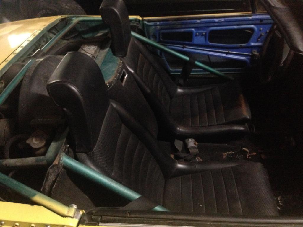
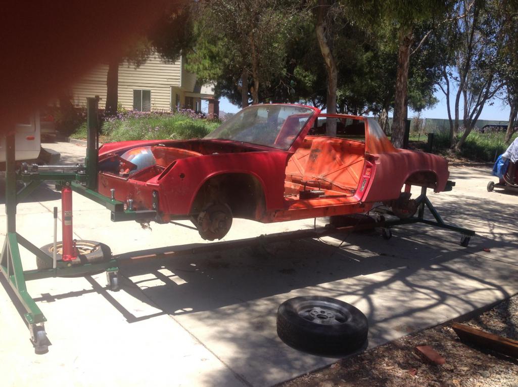
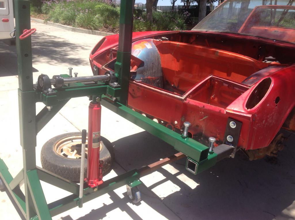
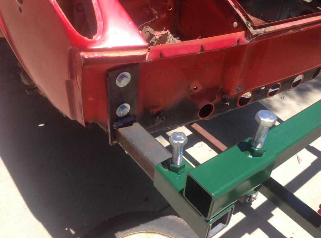
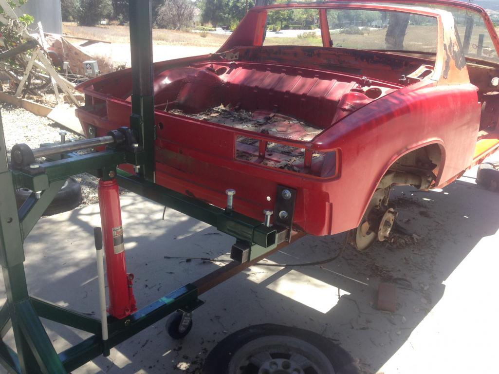
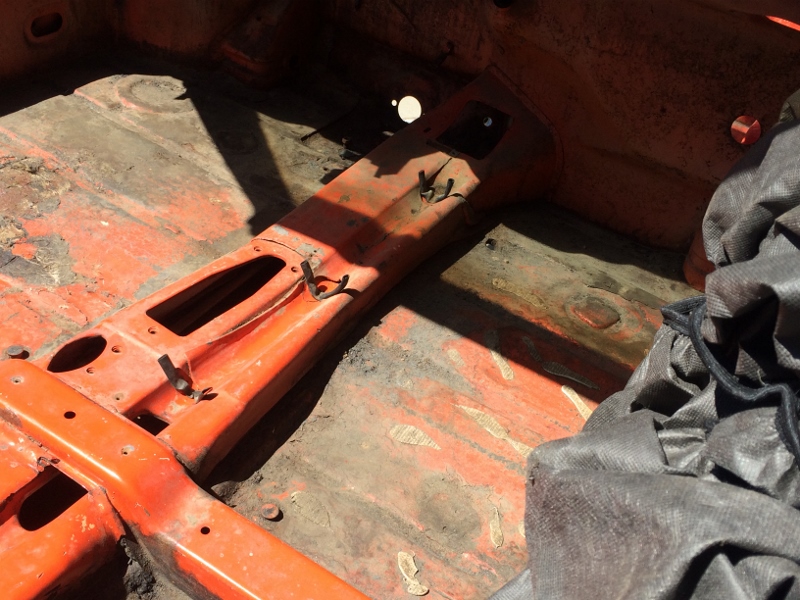
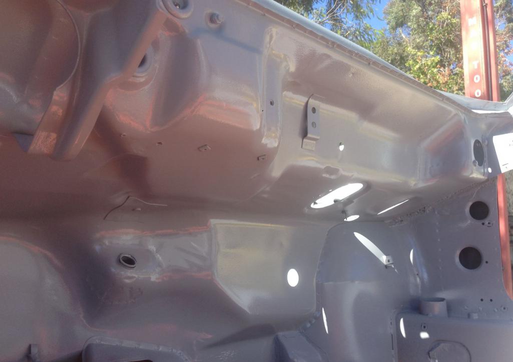
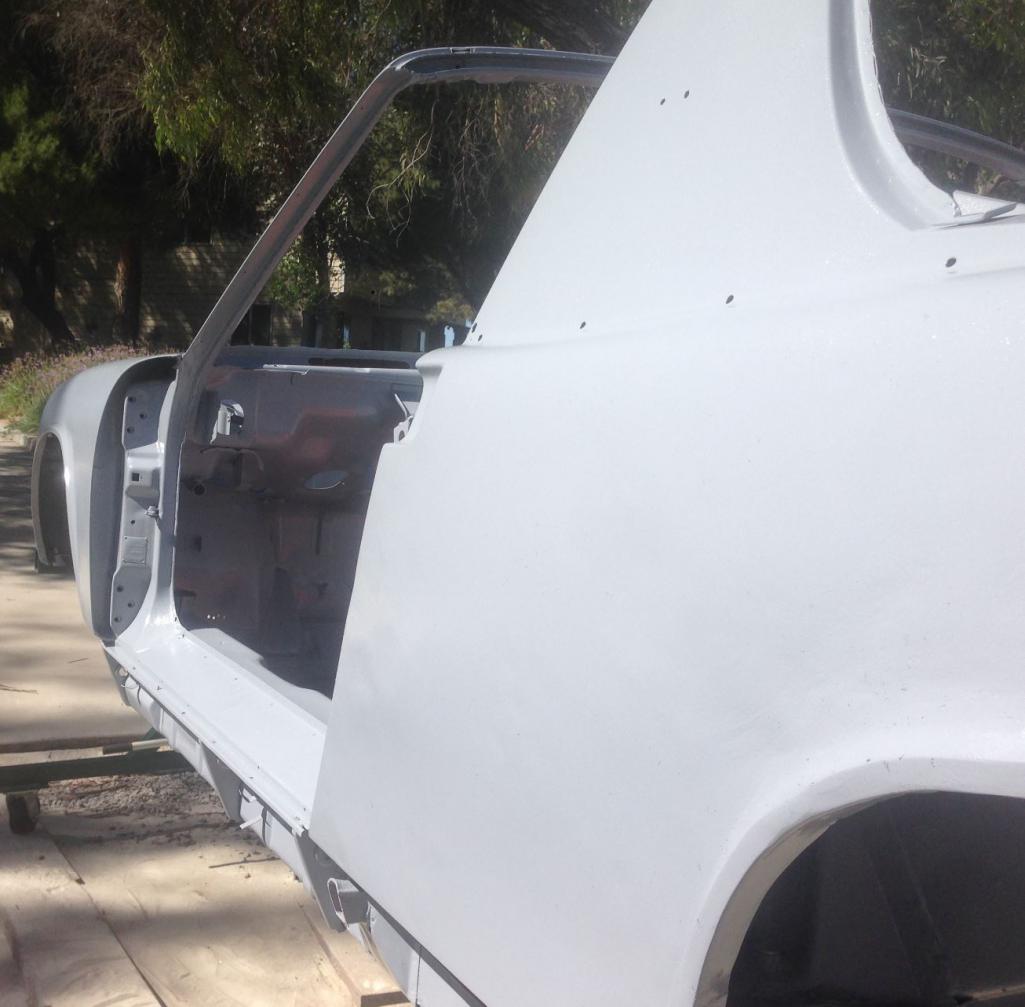
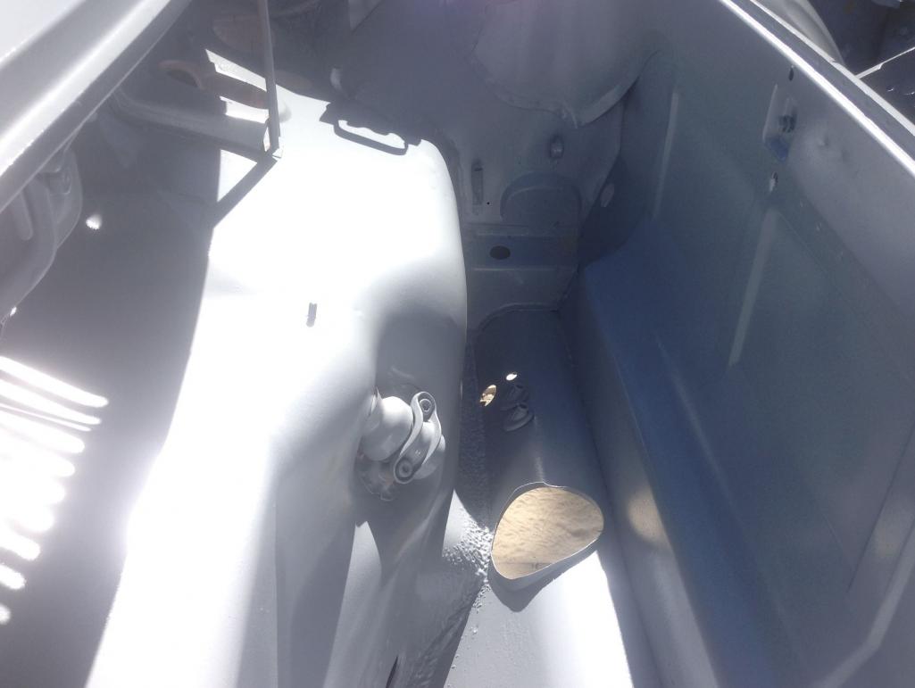
Well here are some more pictures of the progress. We have removed everything inch of wire, grommet, tubing, cable. All we need now is the suspension. Building rotiserrie before i take suspension off. My trusty helper is my son. We are enjoying this project immensely. 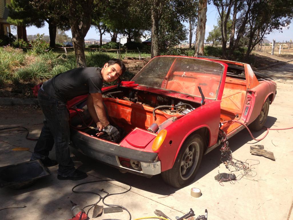
Posted by: Curbandgutter Apr 15 2013, 02:52 PM
More pics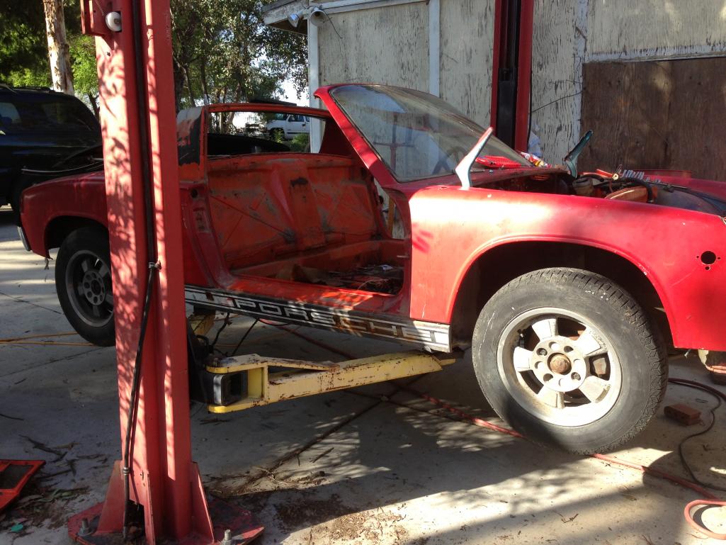
Posted by: Curbandgutter Apr 15 2013, 03:01 PM
Bundle of wires
Attached thumbnail(s)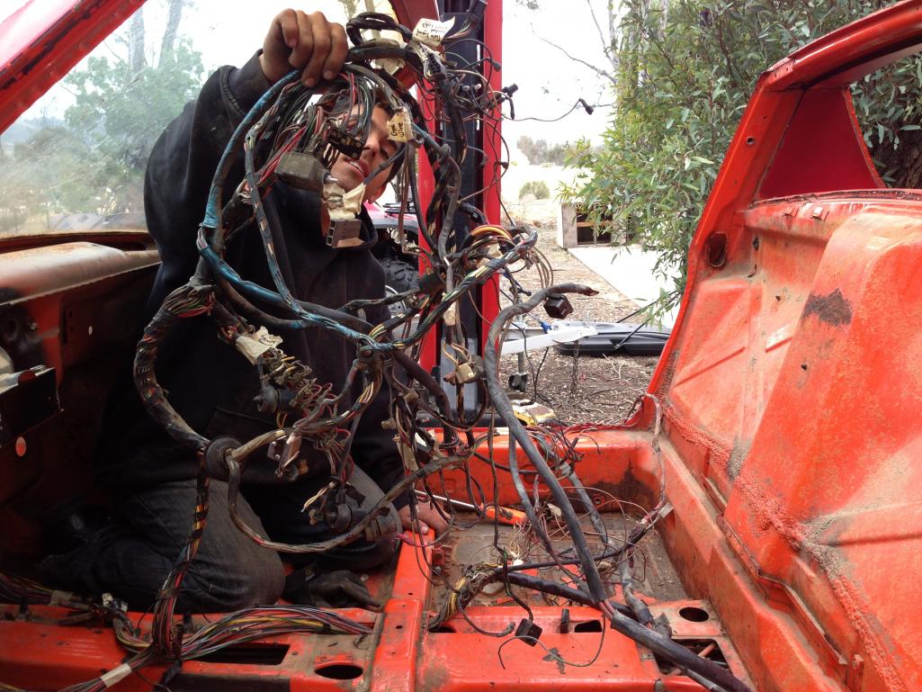
Posted by: bulitt Apr 15 2013, 03:06 PM
Well here are some more pictures of the progress. We have removed everything inch of wire, grommet, tubing, cable. All we need now is the suspension. Building rotiserrie before i take suspension off. My trusty helper is my son. We are enjoying this project immensely.
Good for you! Times like this are so fleeting!
Posted by: BMiller Apr 15 2013, 09:05 PM
Good job so far. Keep it up!
Posted by: Jgilliam914 Apr 16 2013, 01:00 PM
Take good care of that Harness! Your gonna need it when you restore it
Posted by: Curbandgutter Apr 16 2013, 02:22 PM
Thank you for the suggestion. Also with respect to the harness, I'm going to have to do a diet on it as I won't be using any of the engine fuel controls. I'm also going to need some grommets as I found it impossible to remove the harness through the rear firewall without removing the large rubber elbow. Also there were some relays underneath the passenger seats that were completely rusted out. I could not remove them without cutting them out. I will be needing a factory manual to see exactly what those relays are for.
Posted by: Curbandgutter Apr 16 2013, 02:38 PM
I'm also planning on removing the center tunnel and making my own. This can serve various purposes: it makes it easier to re install the wiring harness, the fuel lines, the drive by wire throttle, the hydraulic clutch line, and it gives me the opportunity to install the shifter at the proper height. Also, I have been toying with the idea of bringing a cold air inlet from the front of the car to the rear via this center tunnel. Obviously the cold air/ram tunnel would be separate from the other cables. I could remove the existing fuel tank and buy a cell that fits into the spare tire well. It would be a direct ram of cold air into the cold air box!  Also the center tunnel would be taller and much stiffer than the low profile one that it came with. This would add additional stiffness to the frame. The Sheridan front certainly has some real estate in the front for various ports to accomplish this. What do you guys think?
Posted by: effutuo101 Apr 18 2013, 03:35 PM
keep it up! a lot of work ahead, but it will be worth it!
Posted by: Curbandgutter Aug 4 2014, 01:13 PM
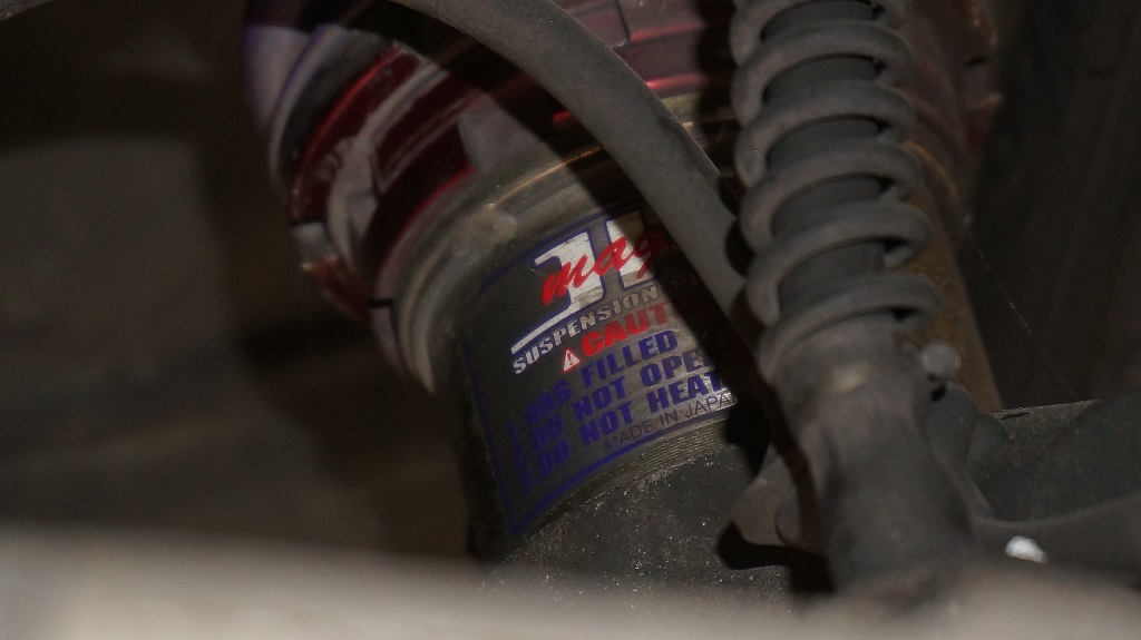
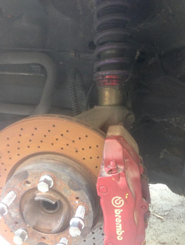
Well it has been a while but I have been collecting "stuff" so that I can start and not have to stop too often. I purchased a 2000 996 C4 that was involved in a fire. I am able to use the full suspension, Brembo big reds, jic coil overs, radiators, ac condensors, power steering, power brakes, transmission, axles, pedal assembly. I am purchasing steel flares this week and then I will be able to start work. I will be posting pictures of the German piece of coal donor.
It is going to be a 916 like you haven't seen yet. Top is coming off, steel speedster humps, lowered floor, lowered glass and raked back. Steel cage/frame. I'm wanting to modify the 996 aftermarket front bumper to work with the 914 front an 916 front flares. I'm also removing the front square pop up lights. The real surprise is what I have planned for the rear fender and quarter panel. More to come.
Posted by: Justinp71 Aug 4 2014, 01:31 PM
Sounds like a good project... funny, one just sold on ebay (not flared though). If you look you can see the radiator behind the seat even, that's new on a v8 car.
http://www.ebay.com/itm/1972-Porsche-914-914-8-speedster-V8-rare-convertible-Renegade-custom-hybrid-/141358887807?pt=US_Cars_Trucks&forcerrptr=true&hash=item20e9a5737f&item=141358887807&nma=true&si=h8Ks%252FrpEPD4QTlNg%252Fj%252FEeFrIv5g%253D&orig_cvip=true&rt=nc&_trksid=p2047675.l2557
Attached thumbnail(s)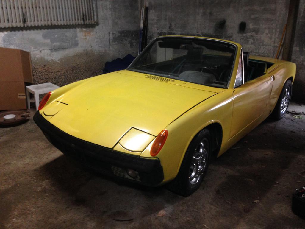
Posted by: Elliot Cannon Aug 4 2014, 02:10 PM
Well it has been a while but I have been collecting "stuff" so that I can start and not have to stop too often. I purchased a 2000 996 C4 that was involved in a fire. I am able to use the full suspension, Brembo big reds, jic coil overs, radiators, ac condensors, power steering, power brakes, transmission, axles, pedal assembly. I am purchasing steel flares this week and then I will be able to start work. I will be posting pictures of the German piece of coal donor.
It is going to be a 916 like you haven't seen yet. Top is coming off, steel speedster humps, lowered floor, lowered glass and raked back. Steel cage/frame. I'm wanting to modify the 996 aftermarket front bumper to work with the 914 front an 916 front flares. I'm also removing the front square pop up lights. The real surprise is what I have planned for the rear fender and quarter panel. More to come.
We're gonna have to see some pictures. If we can't see it, it isn't happening.

Posted by: Curbandgutter Aug 4 2014, 04:11 PM
damm iphone will not hook up to my computer. I'll get pics today though
Posted by: Curbandgutter Aug 4 2014, 04:44 PM
Sounds like a good project... funny, one just sold on ebay (not flared though). If you look you can see the radiator behind the seat even, that's new on a v8 car.
http://www.ebay.com/itm/1972-Porsche-914-914-8-speedster-V8-rare-convertible-Renegade-custom-hybrid-/141358887807?pt=US_Cars_Trucks&forcerrptr=true&hash=item20e9a5737f&item=141358887807&nma=true&si=h8Ks%252FrpEPD4QTlNg%252Fj%252FEeFrIv5g%253D&orig_cvip=true&rt=nc&_trksid=p2047675.l2557
Thanks for the picture but yeah not what I'm doing. That car needs a lot of work. It's not even a 50 footer.
Posted by: 76-914 Aug 4 2014, 06:23 PM
You need that harness up to the 14pin connector at the relay board. The relay board is history.
Posted by: ThePaintedMan Aug 4 2014, 06:43 PM
We're gonna have to see some pictures. If we can't see it, it isn't happening.
 There are a lot of threads where people plan what they're going to do. A couple years later we see the roller cut up and for sale in the classifieds. Wish you luck for sure tho.
Posted by: Curbandgutter Aug 4 2014, 06:47 PM
George, Thank you....I know what you mean. Hopefully that will not be the case here. I almost have everything that I need to get going so its not about not having the parts.
Posted by: Curbandgutter Aug 4 2014, 06:51 PM
OK here are some pictures. 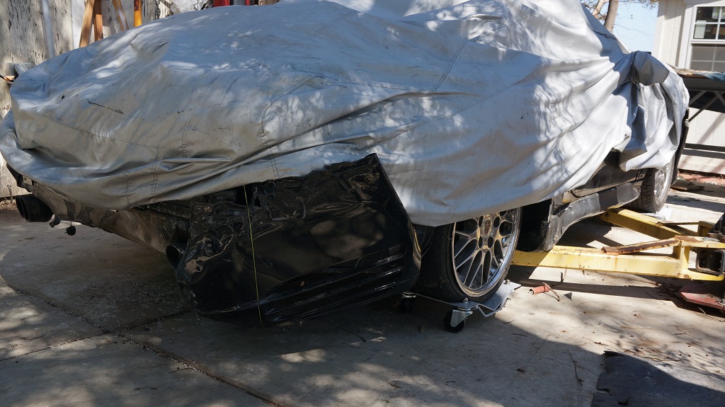
 [attachmentid=461371 ]
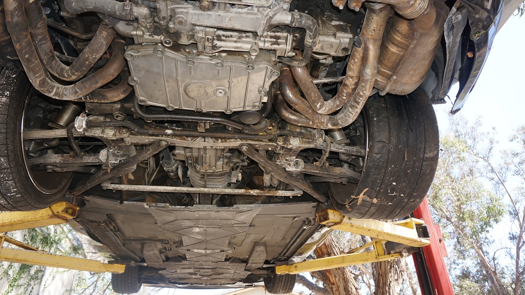
Attached image(s)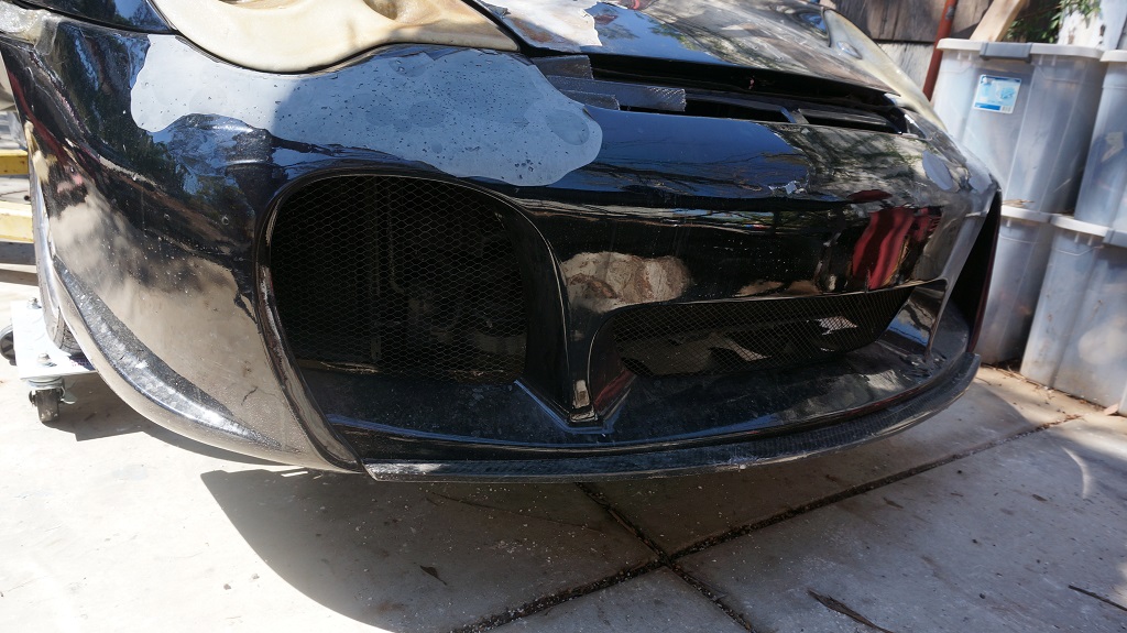
Posted by: BIGKAT_83 Aug 5 2014, 08:01 AM
Well it has been a while but I have been collecting "stuff" so that I can start and not have to stop too often. I purchased a 2000 996 C4 that was involved in a fire. I am able to use the full suspension, Brembo big reds, jic coil overs, radiators, ac condensors, power steering, power brakes, transmission, axles, pedal assembly.
Whats your plan on using the transaxle in mid engine conversion. I don't think you can rotate the 996 transaxle to run in a inverted posistion. Is the ring gear reverseable like in the 930 boxes.

Posted by: Curbandgutter Aug 5 2014, 11:50 AM
Well it has been a while but I have been collecting "stuff" so that I can start and not have to stop too often. I purchased a 2000 996 C4 that was involved in a fire. I am able to use the full suspension, Brembo big reds, jic coil overs, radiators, ac condensors, power steering, power brakes, transmission, axles, pedal assembly.
Whats your plan on using the transaxle in mid engine conversion. I don't think you can rotate the 996 transaxle to run in a inverted posistion. Is the ring gear reverseable like in the 930 boxes.
You can invert the 996 gearbox. Verified with GBOX. Only thing is that I think that I will need to add taller ring and pinion. If I use a 325/30 19 tire with stock rear it will cruise 70 MPH at 2550 rpm. If I use the 3:1 rear end, then it will cruise 70 MPH at 2200 rpm. I'm getting a quote to do the taller rear and LSD. Let's see what it ends up at.
Posted by: Curbandgutter Jun 7 2016, 07:15 PM
It's been a while......life happens. I'm back on track and started to build the rotisserie. I'll finish this weekend and then I'm going to media blast. Enjoy the pics.
Attached thumbnail(s)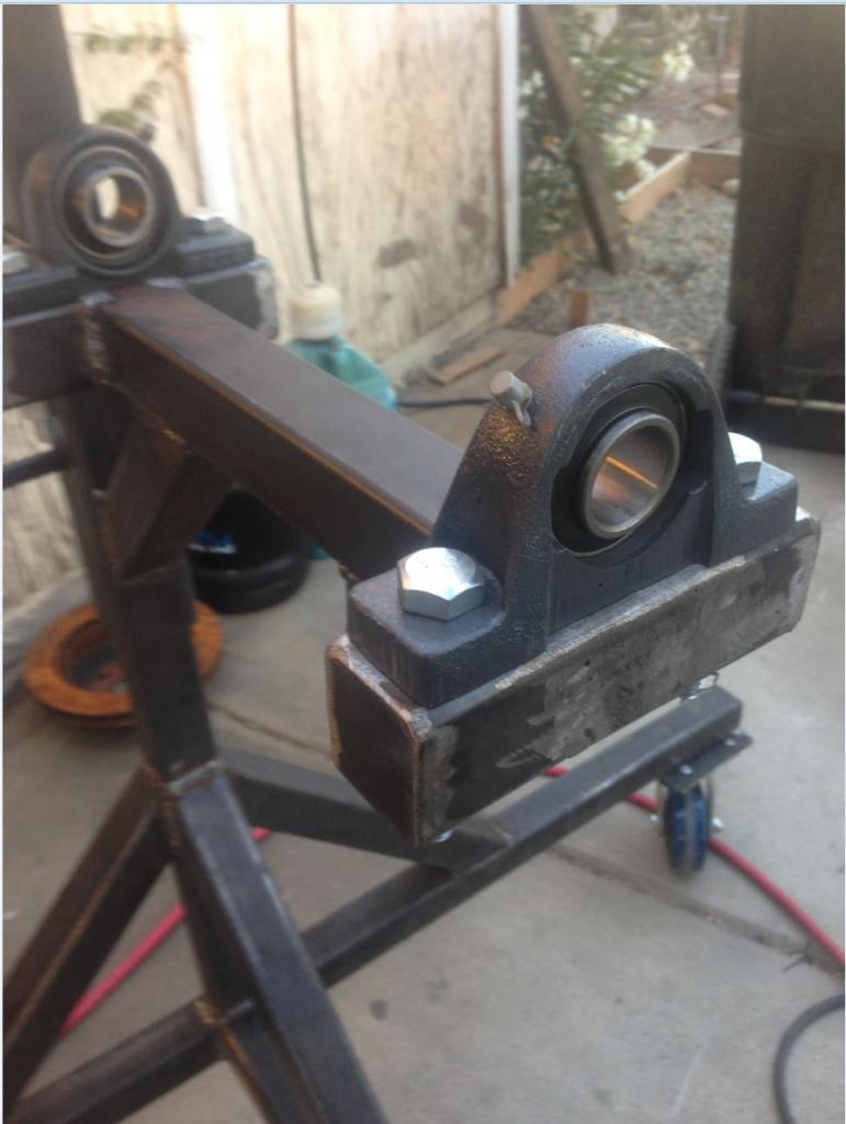
Posted by: rick 918-S Jun 7 2016, 08:44 PM
How'd I miss this? Belated
Posted by: arkitect Jun 8 2016, 06:21 AM
Can't wait to see more.
Dave
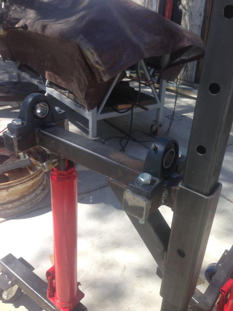
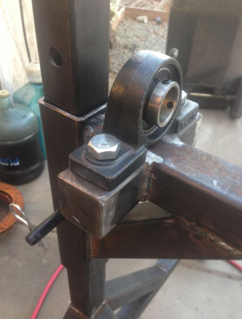
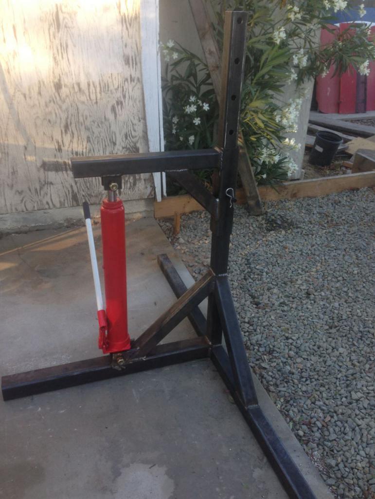
Posted by: Curbandgutter Jun 14 2016, 02:29 PM
Well here is the rotisserie that I made. I took the best ideas from all of the different ones and made my own. I am satisfied with the way the rotisserie came out. I'm now waiting for my wet sandblasting kit from Power Eagle. They are on back order and will be available at end of June. For now I will just pick up the recycled glass and wait.
Attached thumbnail(s)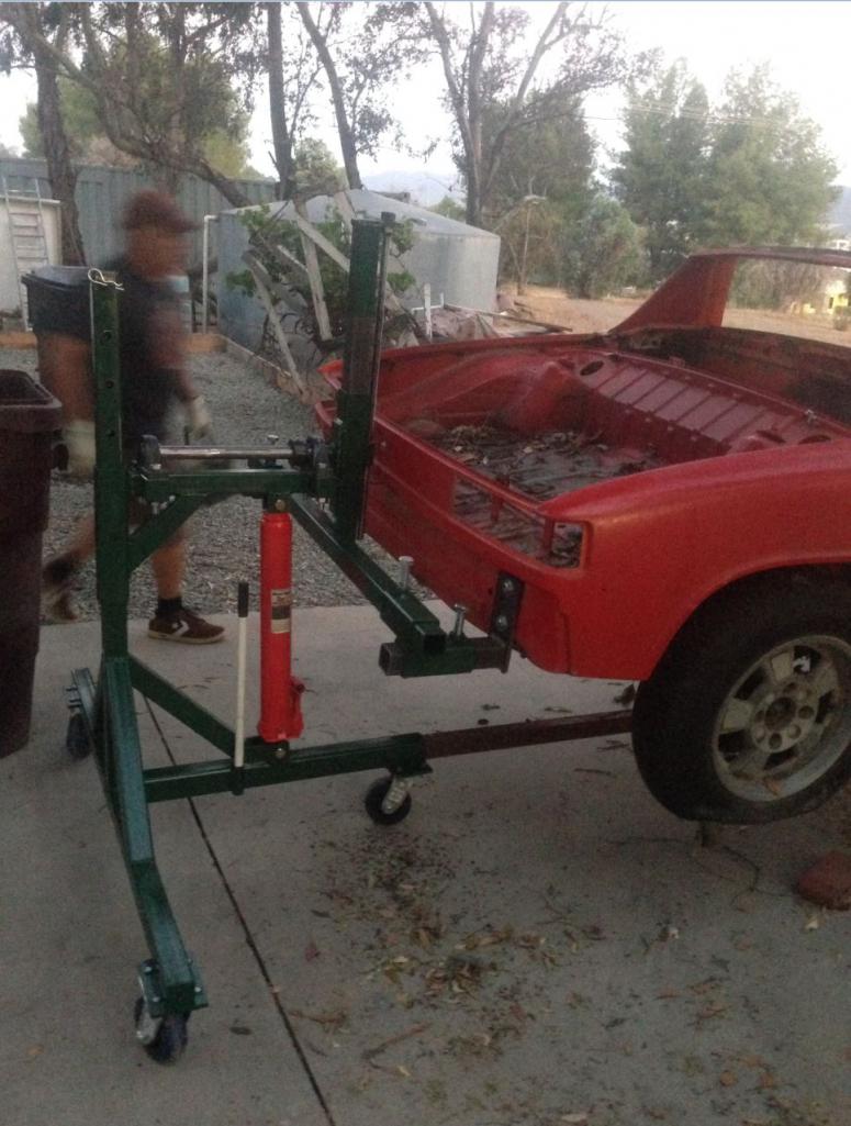
Posted by: Curbandgutter Jun 16 2016, 06:23 PM
How'd I miss this? Belated
Thanks.
Posted by: 76-914 Jun 16 2016, 06:55 PM
Looking forward to this. Damn nice rotisserie. John Deere green from Tractor Supply? ![popcorn[1].gif](style_emoticons/default/popcorn[1].gif)
Posted by: Curbandgutter Jun 17 2016, 09:15 AM
Looking forward to this. Damn nice rotisserie. John Deere green from Tractor Supply?
Posted by: Curbandgutter Jun 17 2016, 09:46 AM
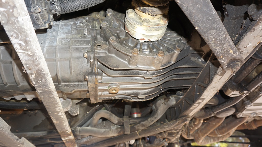
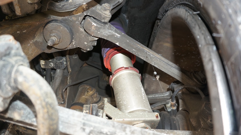
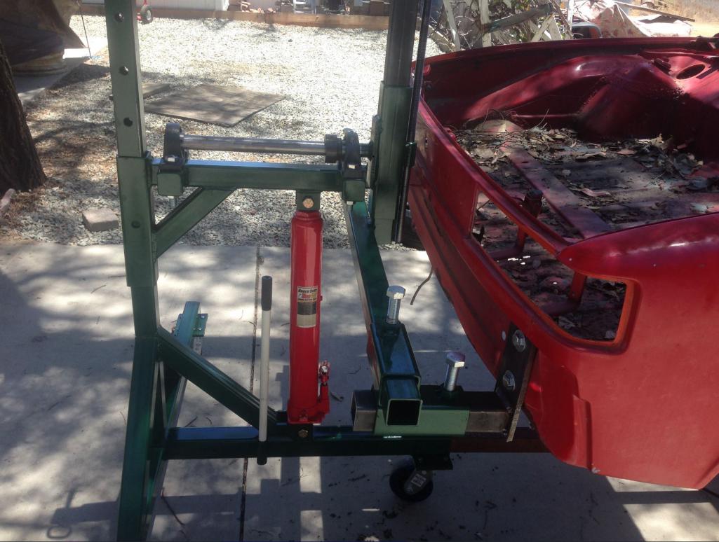
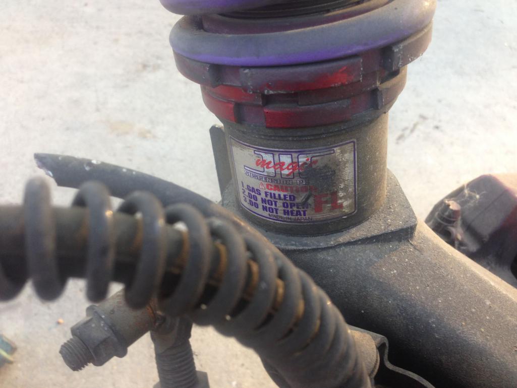
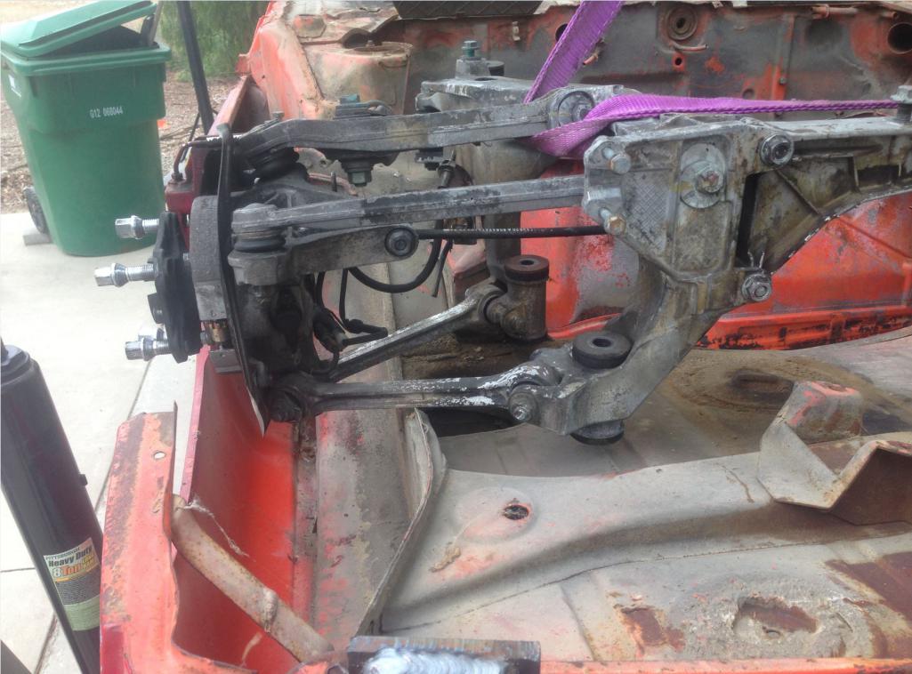
Well since I have to wait until my sand blast kit shows up, I'm taking the front and rear suspension off the 996 to mock up on the 914. Looks like the front will be easy. The rear will require a tube frame. That's OK though since I am planning to tube the rear. I'm planning to pressure wash the suspension this weekend and mock it up on the rotisserie with the car upside down. 
Attached thumbnail(s)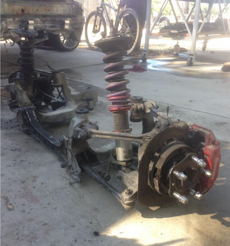
Posted by: 87m491 Jun 17 2016, 09:52 AM
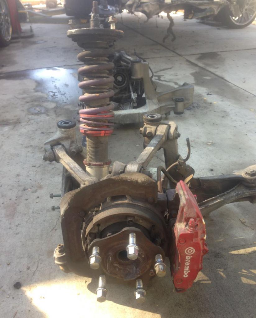
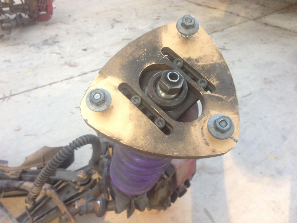
Wow, a ton of adjustment (and adjusters!) on those coil overs.
Well since I have to wait until my sand blast kit shows up, I'm taking the front and rear suspension off the 996 to mock up on the 914. Looks like the front will be easy. The rear will require a tube frame. That's OK though since I am planning to tube the rear. I'm planning to pressure wash the suspension this weekend and mock it up on the rotisserie with the car upside down.
Posted by: 2mAn Jun 17 2016, 10:14 AM
Im not sure which body kit you are looking for but this guy might have a NOS setup for you. He's in Fresno
There is an older body kit still in the box, I don't plan on using it and I'm not sure he was either. I have spare parts as well including doors, quarter panels, seats, etc.
Posted by: Mueller Jun 17 2016, 10:34 AM
Neat project.
For mounting the suspension, what are you using for a datum or reference plane to make sure the a-arms are not tilted too far forward or back? Any part of the suspension that is supposed to be parallel with the floor pan?
Posted by: Curbandgutter Jun 17 2016, 10:35 AM
Im not sure which body kit you are looking for but this guy might have a NOS setup for you. He's in Fresno
There is an older body kit still in the box, I don't plan on using it and I'm not sure he was either. I have spare parts as well including doors, quarter panels, seats, etc.

Posted by: Curbandgutter Jun 17 2016, 10:42 AM
Neat project.
For mounting the suspension, what are you using for a datum or reference plane to make sure the a-arms are not tilted too far forward or back? Any part of the suspension that is supposed to be parallel with the floor pan?
Posted by: 2mAn Jun 17 2016, 10:57 AM
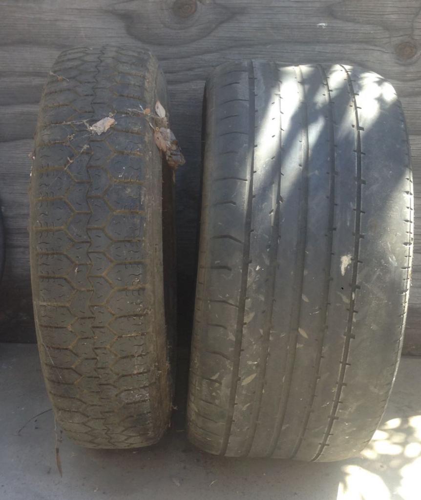
I've really thought it through and finally came to the conclusion that a modified 916 look is what I will do. I will extend the 916 flares enough to cover the 245/18 front tires and 335/18 rear tires. I have thought it through though as I want to stuff the wide tires but I don't want a ridiculous bulge at each corner. I have a couple of tricks up my sleeve to accomplish this though. Also the 996 suspension will make this car to have a 5" wider track in the front and a 4.8" wider track in the rear. It's interesting that the wheelbase of the 914 is 4" longer than the 911??
whats the smallest wheel that you need to clear the brakes? I would aim for that size. 18s are way too big for a 914. 17 would probably look good with that wide body and still fit over the brakes
Posted by: Curbandgutter Jun 17 2016, 11:18 AM
I've really thought it through and finally came to the conclusion that a modified 916 look is what I will do. I will extend the 916 flares enough to cover the 245/18 front tires and 335/18 rear tires. I have thought it through though as I want to stuff the wide tires but I don't want a ridiculous bulge at each corner. I have a couple of tricks up my sleeve to accomplish this though. Also the 996 suspension will make this car to have a 5" wider track in the front and a 4.8" wider track in the rear. It's interesting that the wheelbase of the 914 is 4" longer than the 911??
whats the smallest wheel that you need to clear the brakes? I would aim for that size. 18s are way too big for a 914. 17 would probably look good with that wide body and still fit over the brakes
Attached thumbnail(s)
Posted by: 76-914 Jun 17 2016, 02:05 PM
Damn Bubba, your in my backyard. PM me your address. I'll send you mine. I'd love to "visit" your project while I await my engine seal kit. Kent
Posted by: Curbandgutter Jun 17 2016, 02:35 PM
Damn Bubba, your in my backyard. PM me your address. I'll send you mine. I'd love to "visit" your project while I await my engine seal kit. Kent
Posted by: Andyrew Jun 17 2016, 03:14 PM
I've really thought it through and finally came to the conclusion that a modified 916 look is what I will do. I will extend the 916 flares enough to cover the 245/18 front tires and 335/18 rear tires. I have thought it through though as I want to stuff the wide tires but I don't want a ridiculous bulge at each corner. I have a couple of tricks up my sleeve to accomplish this though. Also the 996 suspension will make this car to have a 5" wider track in the front and a 4.8" wider track in the rear. It's interesting that the wheelbase of the 914 is 4" longer than the 911??
whats the smallest wheel that you need to clear the brakes? I would aim for that size. 18s are way too big for a 914. 17 would probably look good with that wide body and still fit over the brakes
Thats a preference thing for sure.
I run 18's rear and think it looks great. I personally prefer 17's in the front though as to have a little better ride quality.
Posted by: Curbandgutter Jun 17 2016, 07:56 PM
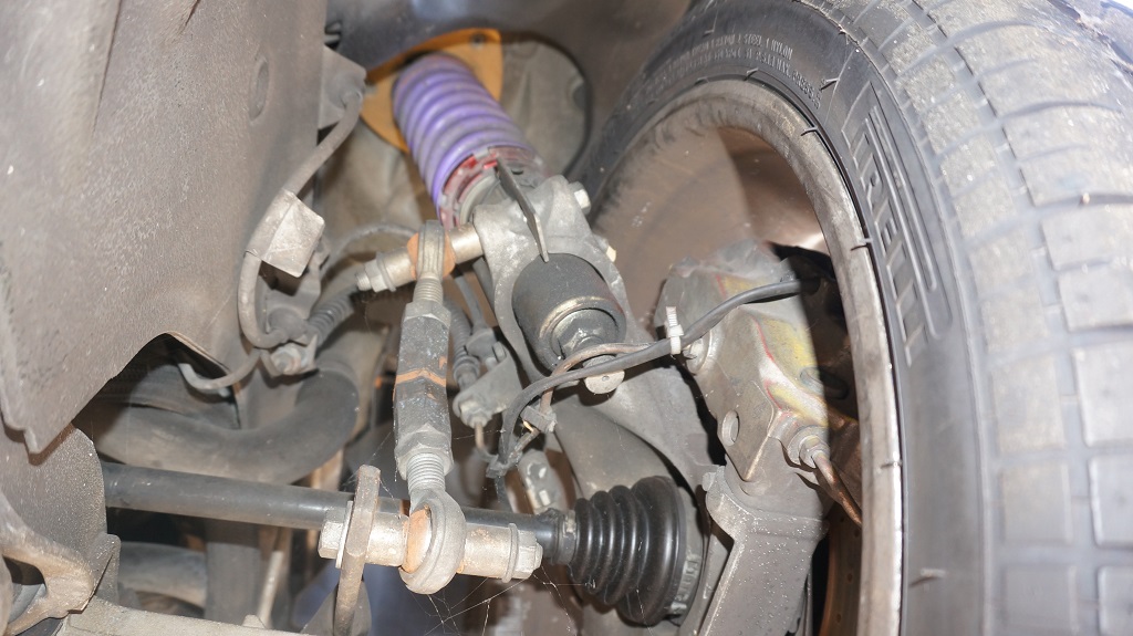
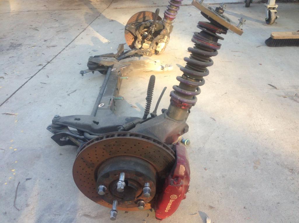
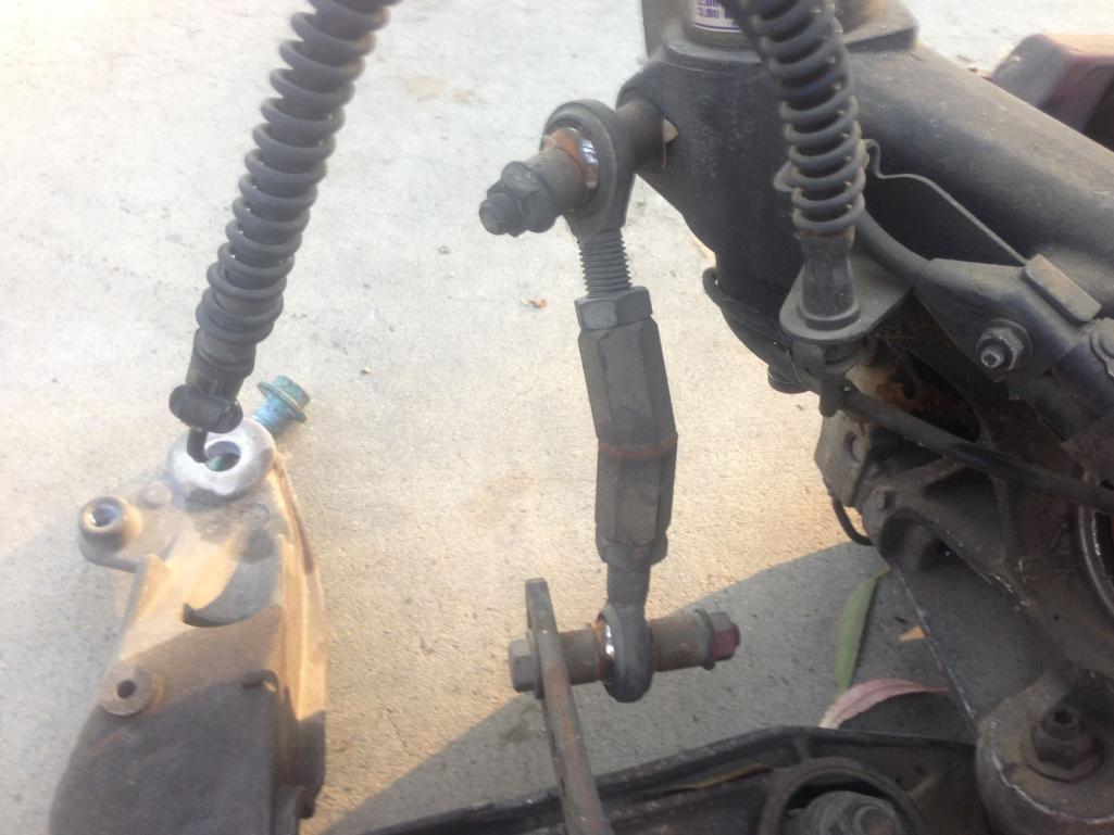
And here is the front suspension. I'll be power washing it Saturday morning and then mocking it up on the 914.
Attached thumbnail(s)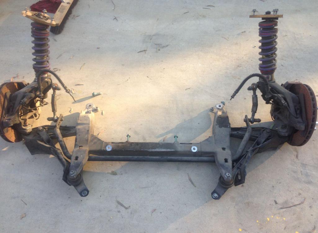
Posted by: Curbandgutter Jun 18 2016, 06:07 PM
Here is the mock up of the rear suspension along with some measurements and an Autocad drawing of the rear end.
Attached thumbnail(s)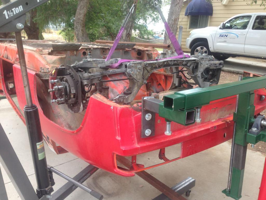
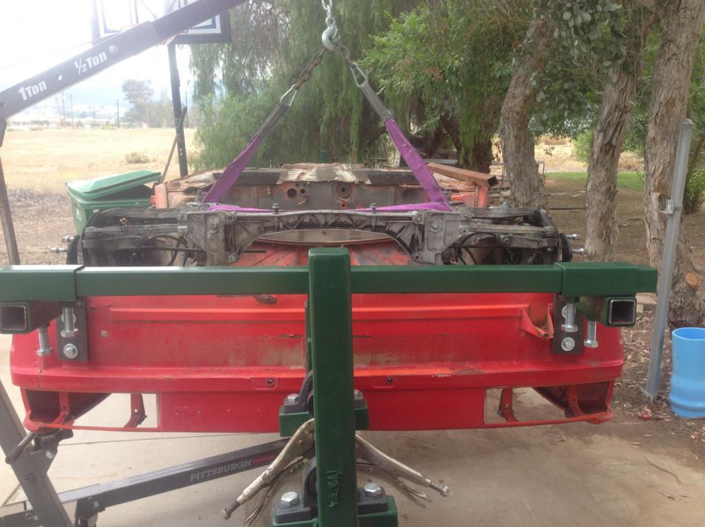
Attached image(s)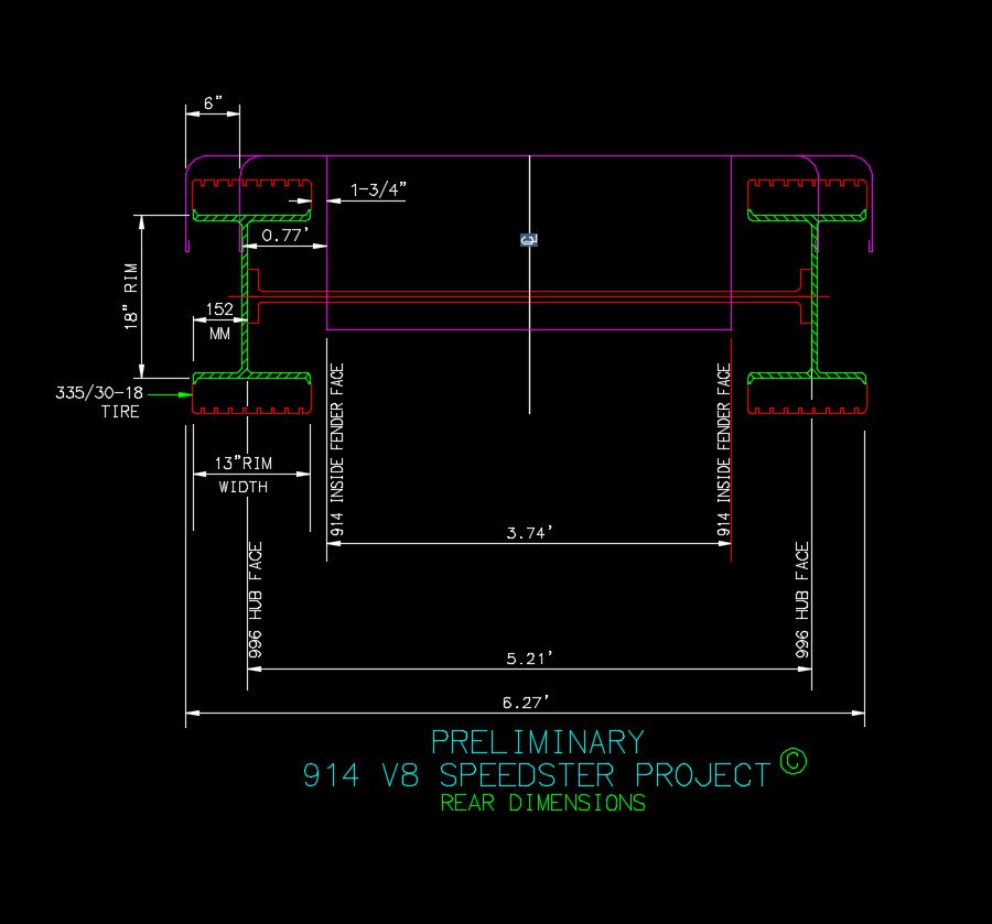
Posted by: Andyrew Jun 18 2016, 07:38 PM
Looks sweet! Lots of work, but that kind of work is Fun work!
Posted by: r_towle Jun 18 2016, 10:12 PM
Challenging exhaust.....
Posted by: Curbandgutter Jun 19 2016, 09:20 PM
Looks sweet! Lots of work, but that kind of work is Fun work!
Posted by: Curbandgutter Jun 19 2016, 09:24 PM
Challenging exhaust.....
Posted by: Mueller Jun 19 2016, 09:52 PM
Challenging exhaust.....
Have you priced that setup yet?
Too $$$ for me!
Would be nice if you could rent it.
Posted by: Curbandgutter Jun 19 2016, 11:02 PM
Little teaser as to what the frame will look like.
Attached thumbnail(s)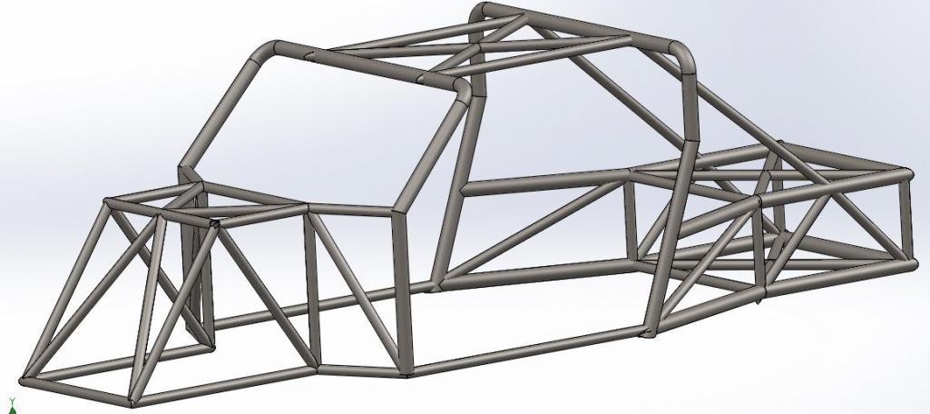
Posted by: Curbandgutter Jun 19 2016, 11:02 PM
Challenging exhaust.....
Have you priced that setup yet?
Too $$$ for me!
Would be nice if you could rent it.
Yeah I know. I'll buy it and then rent it out to the group. But yeah it is pricey.
Posted by: Andyrew Jun 19 2016, 11:15 PM
Little teaser as to what the frame will look like.
That floor looks a little weak, No X brace in the floor or a horizontal where the pedals are?
That rear looks beefy as heck! I think you should remove the rear floor all together. Gonna be hard to raise the engine/trans in.
Posted by: Curbandgutter Jun 20 2016, 10:22 AM
Little teaser as to what the frame will look like.
That floor looks a little weak, No X brace in the floor or a horizontal where the pedals are?
That rear looks beefy as heck! I think you should remove the rear floor all together. Gonna be hard to raise the engine/trans in.
Posted by: 76-914 Jun 21 2016, 09:08 AM
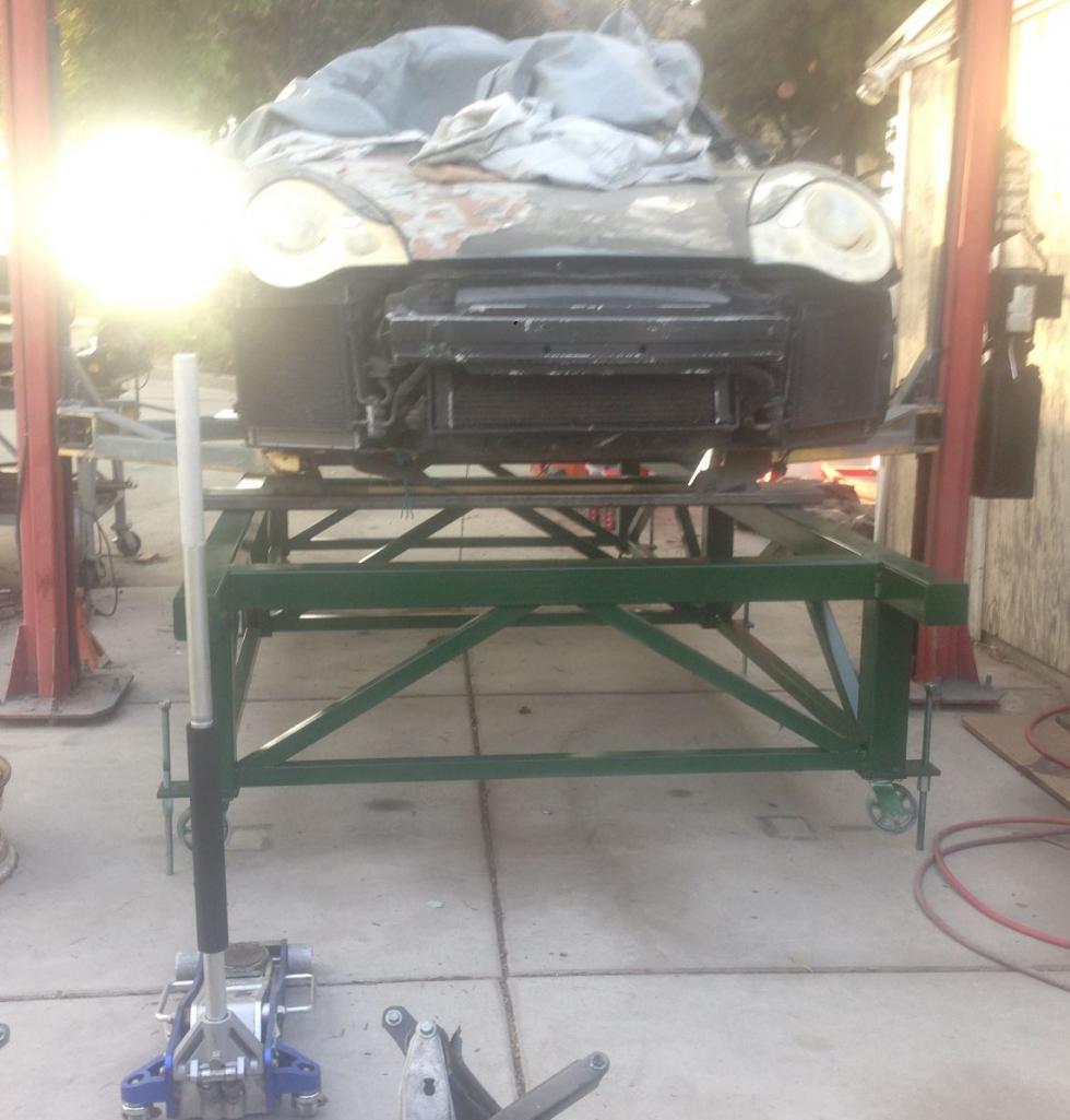
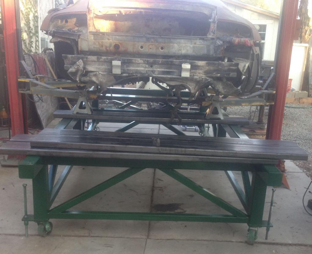
I went to Rudy's Saturday to check out his project and to meet a local fellow teener. He has a nice 2 year project and 5 son's for helpers. That's a good start. Here is a pic of the "suspension" donor car.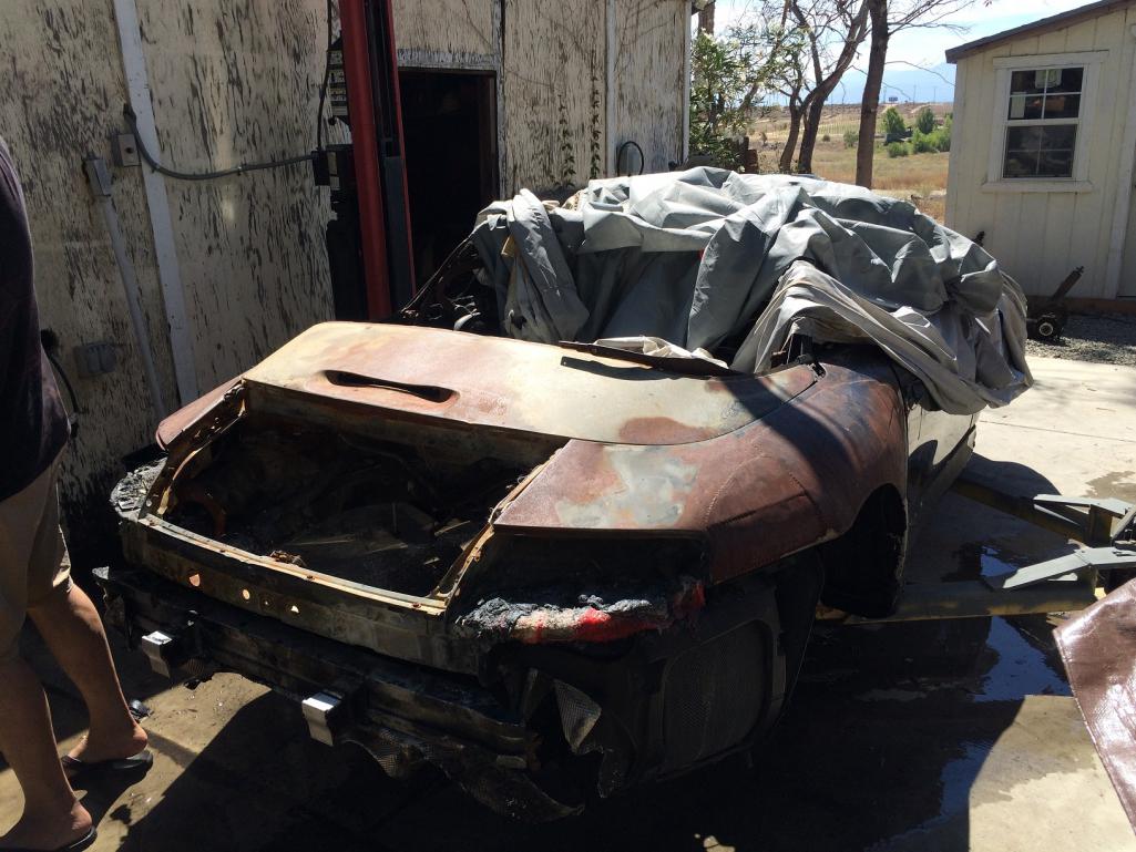
And here is what burned it down. The Stereo or should I say Stereo installer. This is why you don't let the idiots at oil change centers/stereo shops touch your car. Check out the grommets. Oh, wait a minute. There aren't any.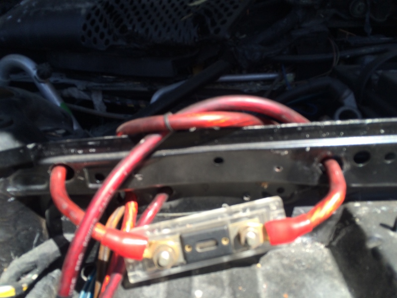
I took a crappy pic here but this is the stereo's main ground block. I has 4 places for bolts to attach to the body. Can you see that is it is held on by one sheet rock screw that isn't even fully pulled down. So in essence, no friggin ground.  And judging from that #4 positive cable I'm guessing it was north of 200w.
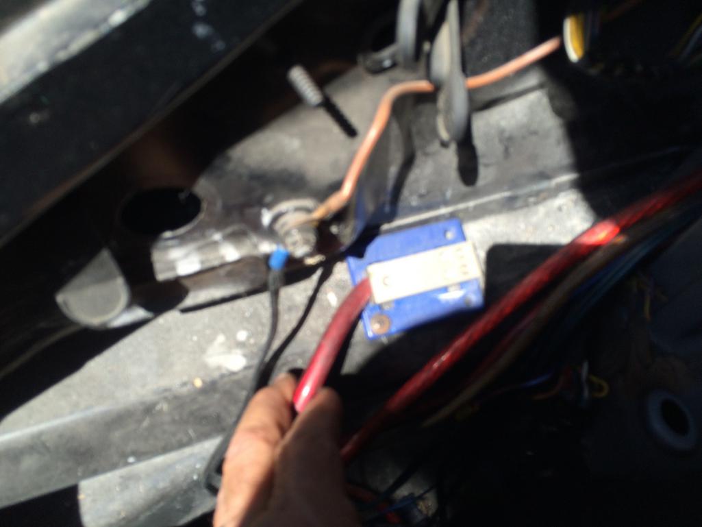
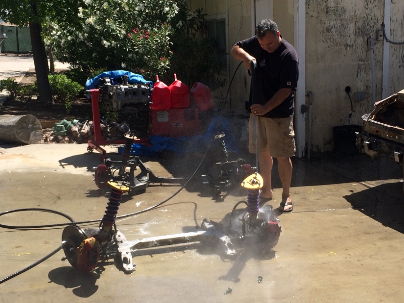
Rudy's '74 in a shell state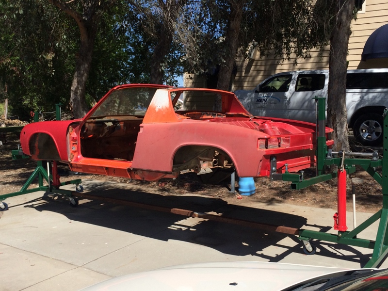
Rudy cleaning the new suspension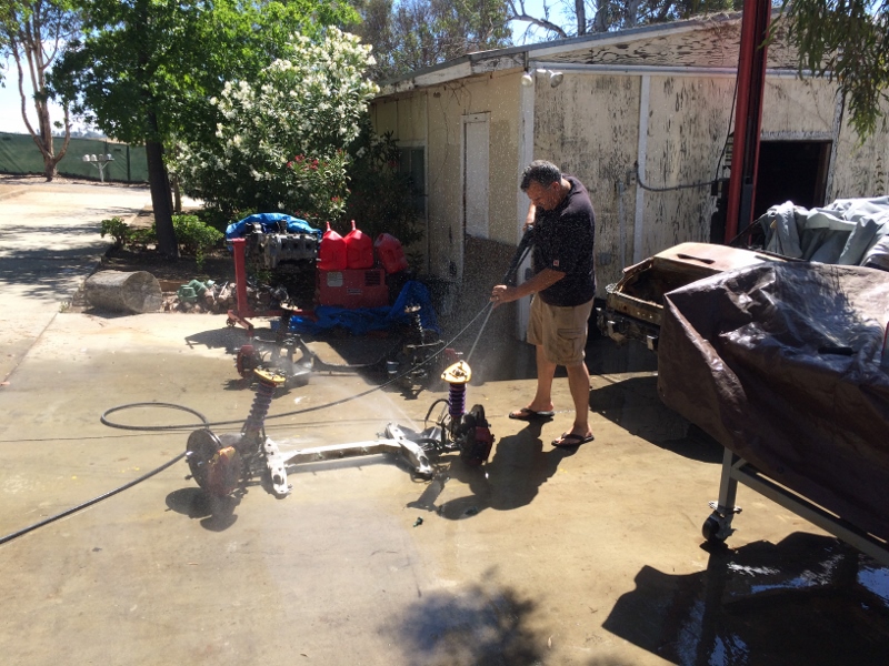
Posted by: Mueller Jun 21 2016, 09:25 AM
I went to Rudy's Saturday to check out his project and to meet a local fellow teener. He has a nice 2 year project and 5 son's for helpers. That's a good start. Here is a pic of the "suspension" donor car.
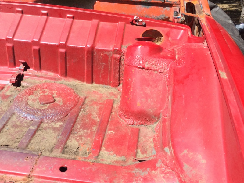
And here is what burned it down. The Stereo or should I say Stereo installer. This is why you don't let the idiots at oil change centers/stereo shops touch your car. Check out the grommets. Oh, wait a minute. There aren't any.
I took a crappy pic here but this is the stereo's main ground block. I has 4 places for bolts to attach to the body. Can you see that is it is held on by one sheet rock screw that isn't even fully pulled down. So in essence, no friggin ground.
And judging from that #4 positive cable I'm guessing it was north of 200w.Rudy's '74 in a shell state
Rudy cleaning the new suspension
Is he related to Z.....flip flops!
hahaha
Posted by: Randal Jun 21 2016, 11:17 AM
Little teaser as to what the frame will look like.
Great project for sure!
Did you check the SCCA rules with regard to how high the roll bar has to be over a helmet? I was surprised how high the roll bar has to be....
The Solo roll bar standards are here:
http://cdn.growassets.net/user_files/scca/downloads/000/013/624/2016-3-25_appendix_C_Solo_Roll_Bar_Standards.pdf?1458925428
Posted by: 914forme Jun 21 2016, 12:21 PM
 The top of that rollbar must be 2" above the drivers helmet, UNLESS that height would interfere with the operation or fit of the OEM top. In that case the driver's helmet must be below a straightedge bridging between the top of the windshield header and the top of the rollbar over the driver's head(the "broomstick test").
So keep your top on
Posted by: Mark Garriott Jun 21 2016, 01:13 PM
Little teaser as to what the frame will look like.
Great project for sure!
Did you check the SCCA rules with regard to high the roll bar has to be over a helmet? I was surprised how high the roll bar has to be....
For SCCA, doesn't the main hoop have to have a cross bar, and all of it in a single plane? I.e. no fore/aft bends.
Posted by: Curbandgutter Jun 21 2016, 03:14 PM
Little teaser as to what the frame will look like.
Great project for sure!
Did you check the SCCA rules with regard to how high the roll bar has to be over a helmet? I was surprised how high the roll bar has to be....
The Solo roll bar standards are here:
http://cdn.growassets.net/user_files/scca/downloads/000/013/624/2016-3-25_appendix_C_Solo_Roll_Bar_Standards.pdf?1458925428
Posted by: Curbandgutter Jun 21 2016, 03:16 PM
I went to Rudy's Saturday to check out his project and to meet a local fellow teener. He has a nice 2 year project and 5 son's for helpers. That's a good start. Here is a pic of the "suspension" donor car.
And here is what burned it down. The Stereo or should I say Stereo installer. This is why you don't let the idiots at oil change centers/stereo shops touch your car. Check out the grommets. Oh, wait a minute. There aren't any.
I took a crappy pic here but this is the stereo's main ground block. I has 4 places for bolts to attach to the body. Can you see that is it is held on by one sheet rock screw that isn't even fully pulled down. So in essence, no friggin ground.
And judging from that #4 positive cable I'm guessing it was north of 200w.Rudy's '74 in a shell state
Rudy cleaning the new suspension
Is he related to Z.....flip flops!
hahaha
hahahaha So Cal boy for sure. You gotta have the board shorts and flip flops. But that day ended up being in triple digits so it was perfect.
Posted by: Curbandgutter Jun 21 2016, 03:18 PM
I went to Rudy's Saturday to check out his project and to meet a local fellow teener. He has a nice 2 year project and 5 son's for helpers. That's a good start. Here is a pic of the "suspension" donor car.
And here is what burned it down. The Stereo or should I say Stereo installer. This is why you don't let the idiots at oil change centers/stereo shops touch your car. Check out the grommets. Oh, wait a minute. There aren't any.
I took a crappy pic here but this is the stereo's main ground block. I has 4 places for bolts to attach to the body. Can you see that is it is held on by one sheet rock screw that isn't even fully pulled down. So in essence, no friggin ground.
And judging from that #4 positive cable I'm guessing it was north of 200w.Rudy's '74 in a shell state
Rudy cleaning the new suspension
Posted by: Randal Jun 21 2016, 03:41 PM
Little teaser as to what the frame will look like.
Great project for sure!
Did you check the SCCA rules with regard to how high the roll bar has to be over a helmet? I was surprised how high the roll bar has to be....
The Solo roll bar standards are here:
http://cdn.growassets.net/user_files/scca/downloads/000/013/624/2016-3-25_appendix_C_Solo_Roll_Bar_Standards.pdf?1458925428
I put a link in my post and here it is again:
http://cdn.growassets.net/user_files/scca/downloads/000/013/624/2016-3-25_appendix_C_Solo_Roll_Bar_Standards.pdf?1458925428
And I believe all the SCCA rules are listed here:
http://cdn.growassets.net/user_files/scca/downloads/000/010/060/2015-10-26_SCCA_Solo_Rules_book_online_reduced.pdf?1445897037
Posted by: Curbandgutter Jun 21 2016, 03:43 PM
Well I started to analyze the frame and found that the front windshield bar (the one in red) will need to be upsized. I wasn't expecting that. Also, I wasn't expecting to stiffen the longs (n14 to n13) but after today's, result, looks like it's a must to stiffen the longs even with a roll cage. 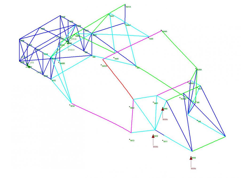
Posted by: jd74914 Jun 21 2016, 11:40 PM
Sweet! You don't see too many people doing FEA iterations on chassis. 
What software package is that? Almost looks like Ansys APDL or maybe more like Grape? You're modeling with beam elements or trusses? Can you glue a shell element floor on to better match reality? In one of the racecars I worked on laminating a thin carbon shear panel on the floors increased stiffness by 25-30% (experimentally verified via twist test too).
I think you're seeing artificially high loads in N43A because of the huge open box in the cockpit. If you add triangulation near the doors and closer the floor I bet you'll move some of that load path (if my visual FEA makes any sense haha).
Your loading seems a little weird. Why load the lower arms so highly in the vertical direction? They shouldn't see all that much vertical force since it's really all desisted by the spring/damper unit. Why not model the suspension in as an infinitely stiff member and then load with bump, lateral, and longitudinal forces? Then you wouldn't have to draw a free body diagram to figure out point loads.
With actual loading N36B might be more heavily loaded than you think (and in some combined weird bending/buckling mode so it probably needs a big safety factor). If you're doing frame stiffness twisting it (via moment about the front suspension nodes with the back fixed) seems more widely accepted than loading one side. There is a good SAE paper on it, I might be able to find it somewhere.
Sorry if you know all that stuff already. I'm not a mechanics guy by any means but I've spent a bunch of time doing chassis design/analysis for some tube frame racecars and a Lotus.
Posted by: Curbandgutter Jun 22 2016, 09:44 AM
Sweet! You don't see too many people doing FEA iterations on chassis.
What software package is that? Almost looks like Ansys APDL or maybe more like Grape? You're modeling with beam elements or trusses? Can you glue a shell element floor on to better match reality? In one of the racecars I worked on laminating a thin carbon shear panel on the floors increased stiffness by 25-30% (experimentally verified via twist test too).
I think you're seeing artificially high loads in N43A because of the huge open box in the cockpit. If you add triangulation near the doors and closer the floor I bet you'll move some of that load path (if my visual FEA makes any sense haha).
Your loading seems a little weird. Why load the lower arms so highly in the vertical direction? They shouldn't see all that much vertical force since it's really all desisted by the spring/damper unit. Why not model the suspension in as an infinitely stiff member and then load with bump, lateral, and longitudinal forces? Then you wouldn't have to draw a free body diagram to figure out point loads.
With actual loading N36B might be more heavily loaded than you think (and in some combined weird bending/buckling mode so it probably needs a big safety factor). If you're doing frame stiffness twisting it (via moment about the front suspension nodes with the back fixed) seems more widely accepted than loading one side. There is a good SAE paper on it, I might be able to find it somewhere.
Sorry if you know all that stuff already. I'm not a mechanics guy by any means but I've spent a bunch of time doing chassis design/analysis for some tube frame racecars and a Lotus.
Now that's what I'm talking about!
 Love this kind of input. Now to answer some of your questions. The lower A arms were not loaded, what you are seeing is the 3 points where the suspension cradle is bolted to the chassis. The 900 lb vertical load represents a 5g load on the wheel. The next step will be to simultaneously load a 900 lb load in a downward fashion on the opposing suspension cradle support points to create a couple, or rather twisting of the frame as you mentioned. I will be running the same scenario at the rear and then run another scenario to simulate bending forces in the frame. I will go ahead and model the floor and both firewalls with plate elements and see what happens. Might as well model the "longs" as well. this will give a better representation of the behavior.
 I'm modeling with beam elements with fixed joints in all directions being that the joints will be notched and welded.
I would love to get my hands on that SAE paper. I'm sure that I will learn a couple of things.
Posted by: Mueller Jun 22 2016, 02:07 PM
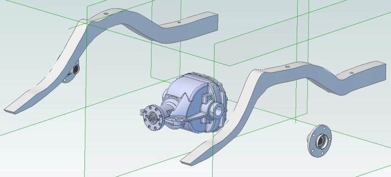
Are you going to model the suspension?
If so check out GrabCAD, I got the CV joints and center section from there (I modeled the rest)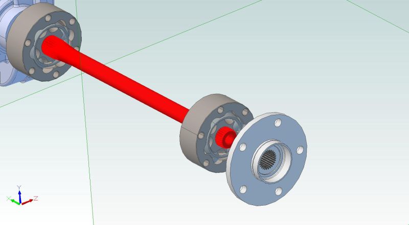
Posted by: Curbandgutter Jun 22 2016, 03:18 PM
Are you going to model the suspension?
If so check out GrabCAD, I got the CV joints and center section from there (I modeled the rest)
Posted by: 914forme Jun 22 2016, 03:33 PM
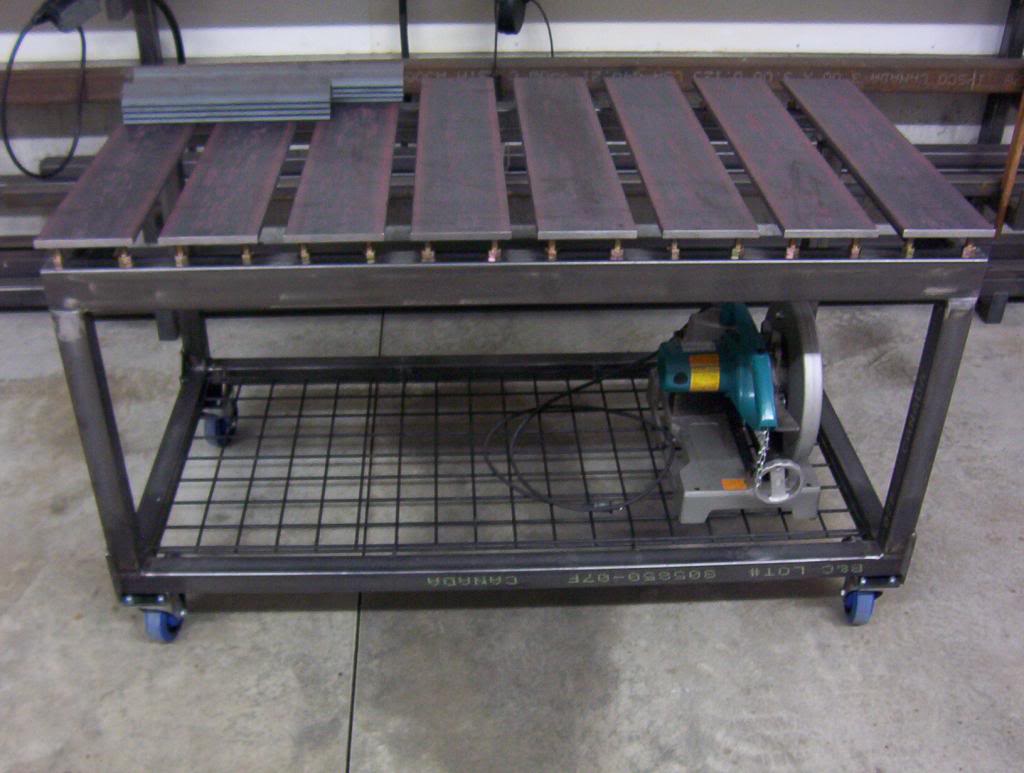
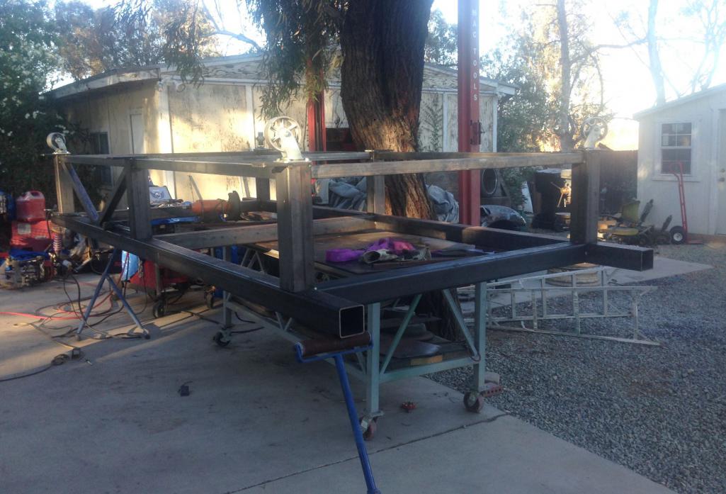
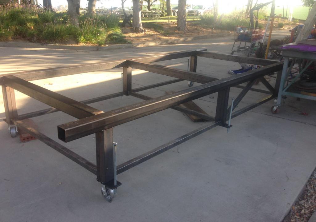
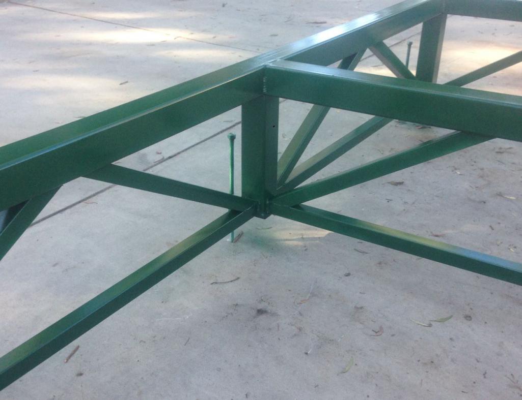
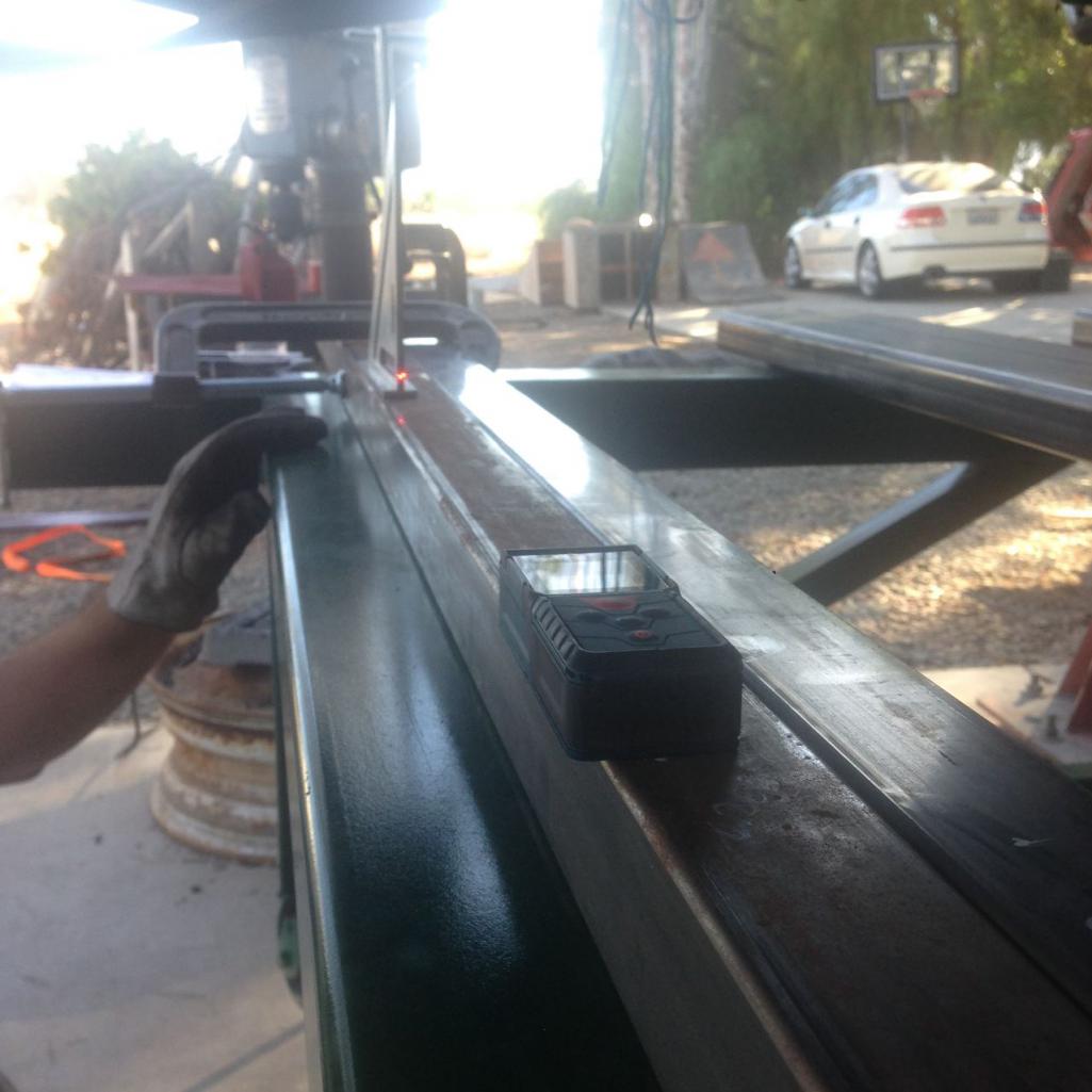
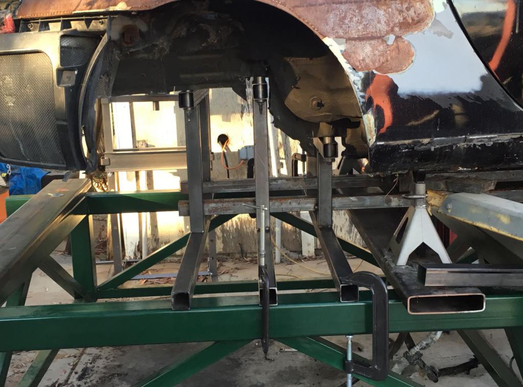
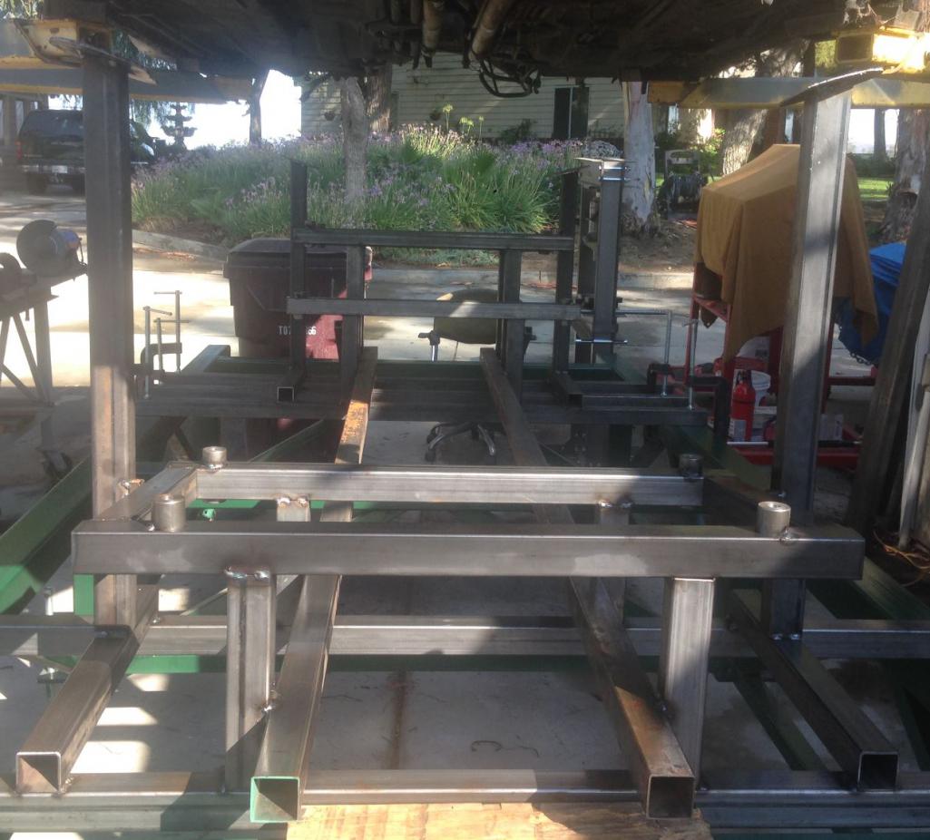
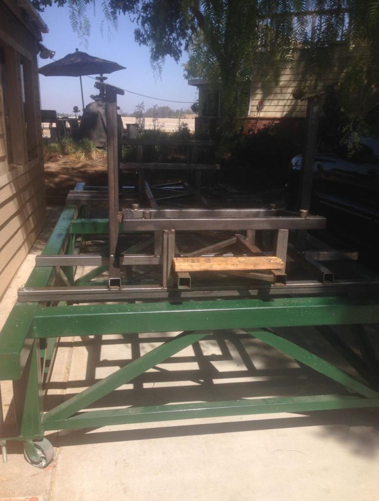
The next item on the list is to build the frame table and to mount the 996 to get all of the suspension pick up points tabulated. Then mount the 914 to start building the chassis with the same suspension pick up points built in. I'll be using a plumb bop and a laser meter to measure and square every thing. It's finally coming together.
Hoping it is built with I beams and 1/2" plate, so you can weld to it. In reality the I beams are fine, you should make the plate float on individual sections. So you can level the plate separate of the frame.
So it looks kinda like this on a much larger scale.
Not mine but highly admired from the Garage Journal Forum.
Posted by: Curbandgutter Jun 22 2016, 05:35 PM
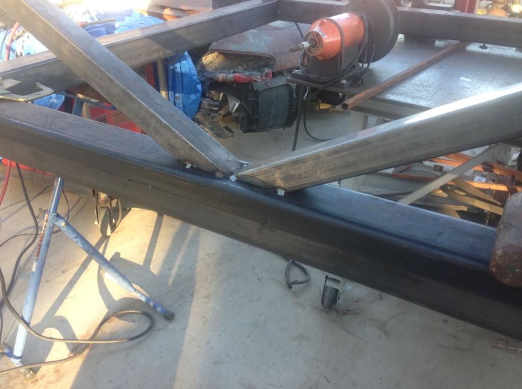
I am making it out of 4x4 tubing. The tubing has much tighter mill tolerances than hot rolled I-beams. Also square tubing is much better than an I-beam in torsion. To make it out of an I-beam I would have to have it blanchard ground. I'm going with 4x4x3/16 frame with six 4x4x3/16 legs. All cross braced with 4 casters and 6 leveling screws. I'll tack weld on the ground enough so that I can raise and assemble. Then I will level all six legs with my survey equipment. Once leveled I will continue welding all seams a little at a time and from opposing corners so that the table does not warp. Then I will finish in that same Hunter Green as the rotisserie. That small chassis table looks like it's awesome for small projects though.
Posted by: Curbandgutter Jun 22 2016, 06:02 PM
I am making it out of 4x4 tubing. The tubing has much tighter mill tolerances than hot rolled I-beams. Also square tubing is much better than an I-beam in torsion. To make it out of an I-beam I would have to have it blanchard ground. I'm going with 4x4x3/16 frame with six 4x4x3/16 legs. All cross braced with 4 casters and 6 leveling screws. I'll tack weld on the ground enough so that I can raise and assemble. Then I will level all six legs with my survey equipment. Once leveled I will continue welding all seams a little at a time and from opposing corners so that the table does not warp. Then I will finish in that same Hunter Green as the rotisserie. That small chassis table looks like it's awesome for small projects though.
Attached image(s)
Posted by: jd74914 Jun 22 2016, 09:58 PM
Now that's what I'm talking about!
Love this kind of input. Now to answer some of your questions. The lower A arms were not loaded, what you are seeing is the 3 points where the suspension cradle is bolted to the chassis. The 900 lb vertical load represents a 5g load on the wheel. The next step will be to simultaneously load a 900 lb load in a downward fashion on the opposing suspension cradle support points to create a couple, or rather twisting of the frame as you mentioned. I will be running the same scenario at the rear and then run another scenario to simulate bending forces in the frame. I will go ahead and model the floor and both firewalls with plate elements and see what happens. Might as well model the "longs" as well. this will give a better representation of the behavior. I'm modeling with beam elements with fixed joints in all directions being that the joints will be notched and welded.
I would love to get my hands on that SAE paper. I'm sure that I will learn a couple of things.
I get worried that people will take offense to comments like those sometimes. Gotcha, I just looked at your pictures again; didn't realize the 996 stuff was all on a subframe. Now it all makes sense.
Looking at that model again it might get stiffer if you switch from the bent front windshield frame halo-style bar rearward facing bars like found in a non-halo cage. Then you'd spread the longitudinal bars (N44 and N43 maybe) out towards the edges moving them further from your head and building a better node at the windshield corners. I just get scared seeing cross-bracing put hoops in bending. It might also be worth switching around some of the triangulation (ie: in front of and behind the door) to meeting at the same places to form some "super nodes." I noticed on the full tube chassis that this seemed to help stiffness without any weight penalty. The x-bracing on top and bottom of the rear might make maintenance very difficult. I did this over a chain drive differential in the name of stiffness and really hated myself for it after the fact. You could probably get most of the stiffness with a bolted shear panel. Hopefully that makes some sense; I can draw it tomorrow really quickly too.
The 5g load is pretty conservative; I've always designed around 3g bump, 2g lateral, and 2g longitudinal loading (though not all at the same time since tire friction circles limit the combined grip) and haven't had many problems. Your analysis plan sounds good to me! Unfortunately I'm at a conference right now and having trouble remoting into my regular computer to look but I'll check for the paper as soon as I get home.
Totally unrelated to the design stuff, but when you notch everything be sure to drill small holes in all of the receiving tubes at the joints. Being able to back purge while welding makes the whole process much better. You have less problems with oils, etc. running out and end up with much higher quality welds.

Posted by: Curbandgutter Jun 23 2016, 10:30 AM
Thank You JD. I appreciate your excellent input.
Posted by: Curbandgutter Jun 23 2016, 08:01 PM
2g Lateral Load at rear yields a 1/16" lateral deflection 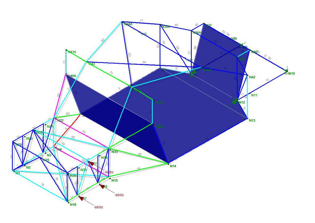
3g Couple at rear yields a 0.114 vertical deflection 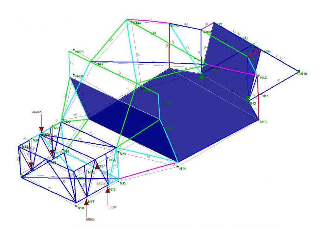
3g Couple at front yields a 0.10" vertical deflection 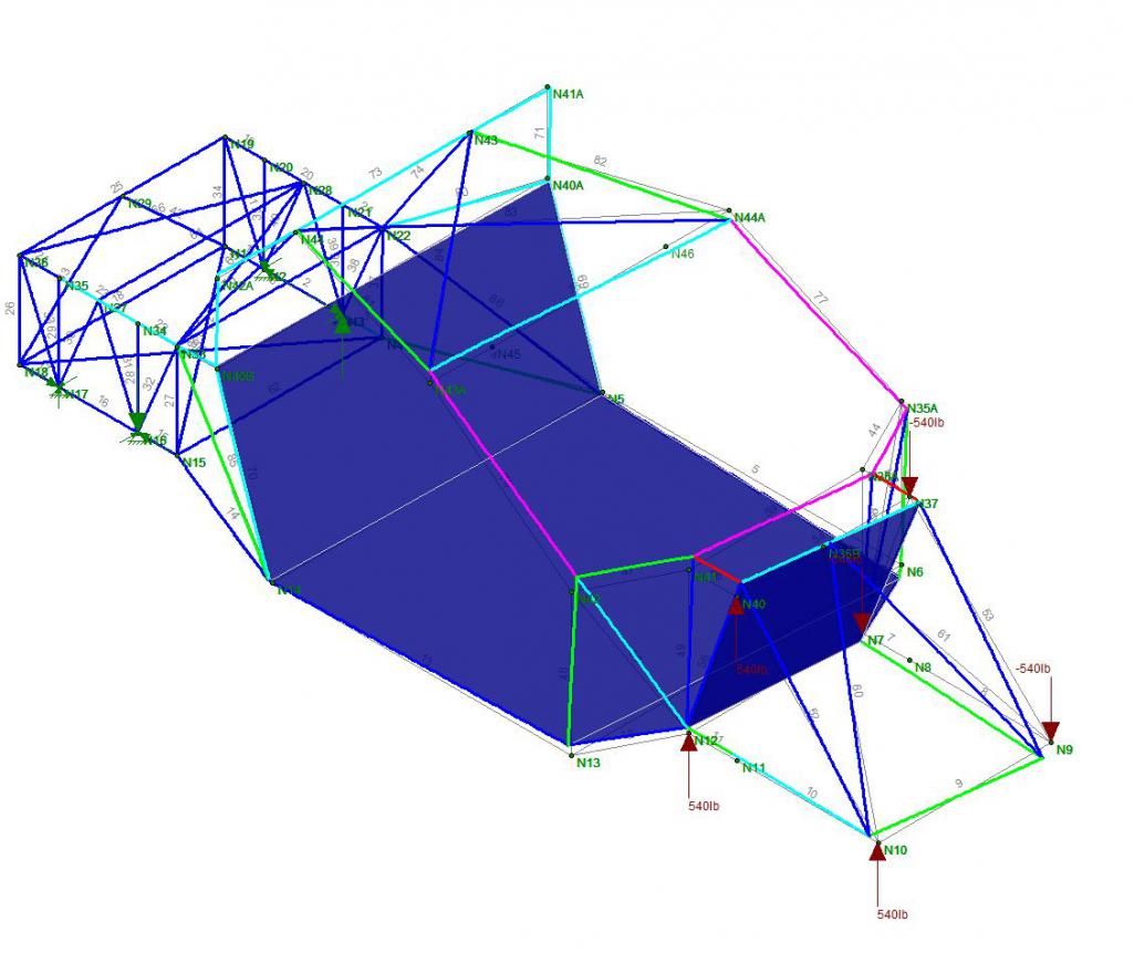
2g Lateral in front yields a WHOPPING 0.70" lateral defelction. This is the worst case. It makes sense too in that the hole where the engine is allows this deflection. I'll have to fix that somehow. I have to wait until the motor is in to add a removable cross brace or just live with it. We will see.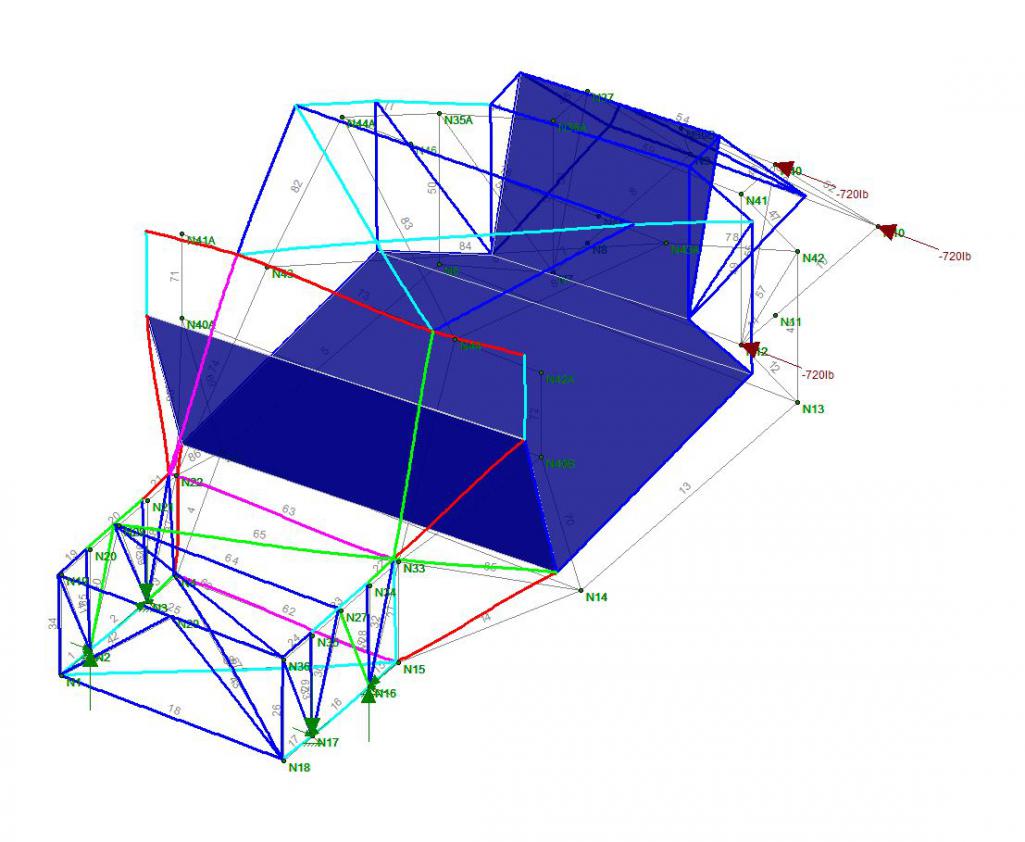
Posted by: Curbandgutter Jun 23 2016, 08:05 PM
I'm feeling pretty good about this chassis .
Posted by: jd74914 Jun 23 2016, 10:08 PM
2g Lateral Load at rear yields a 1/16" lateral deflection
3g Couple at rear yields a 0.114 vertical deflection
3g Couple at front yields a 0.10" vertical deflection
2g Lateral in front yields a WHOPPING 0.70" lateral defelction. This is the worst case. It makes sense too in that the hole where the engine is allows this deflection. I'll have to fix that somehow. I have to wait until the motor is in to add a removable cross brace or just live with it. We will see.
Nice! Those numbers look great!
If you have time it might be interesting to run a case with a bunch of tubes connecting the rough engine mount locations into one node. At least it'd give you some idea of how much deflection the engine stops (assuming it's not super softly mounted). I bet with an "engine" surrogate in there you'd get a lot of the 0.70" back without making any other changes. Adding a bolt-on stressed panel under the engine (could double as a belly pan for aero) would bring back a bunch of stiffness too.
Two pure curiosity questions...How much does it weigh? What software are you using for FEA?
Posted by: Curbandgutter Jun 24 2016, 11:52 AM
That did it. Since the lower frame is flush with the bottom pan of the car. I can bolt on a plate along the bottom and it totally fixed the flex. The flex now is 0.1" as opposed to 0.7"! I like the way you think. The bottom plate will also blend into a rear diffuser. I am planning on exiting my exhaust above the rear bumper line.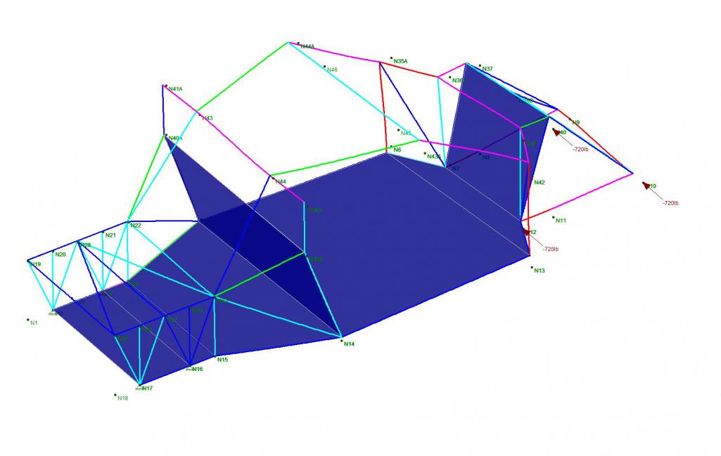
With regard to weight it will add about 150 lbs. However, the front and rear hood, and the front and rear bumpers will be fiberglass. I'm going with about 600 HP  so the extra weight will not be a distraction.
Posted by: jd74914 Jun 27 2016, 09:09 AM
That did it. Since the lower frame is flush with the bottom pan of the car. I can bolt on a plate along the bottom and it totally fixed the flex. The flex now is 0.1" as opposed to 0.7"!
Fantastic! Easy fix! My guess is that you will retain nearly all of the added rigidity even if you have to cut some holes in it for access to things like oil filters, etc.
The weight doesn't seem bad at all, especially considering that you are cutting out existing structure and using some glass parts.
Is this design using different diameter/wall thickness tubing?
Posted by: Curbandgutter Jun 27 2016, 04:51 PM
It uses thick tubing for the main hoops and thinner everywhere I can.
Posted by: Curbandgutter Jun 27 2016, 04:56 PM
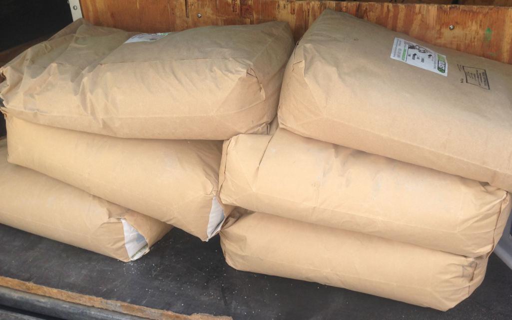
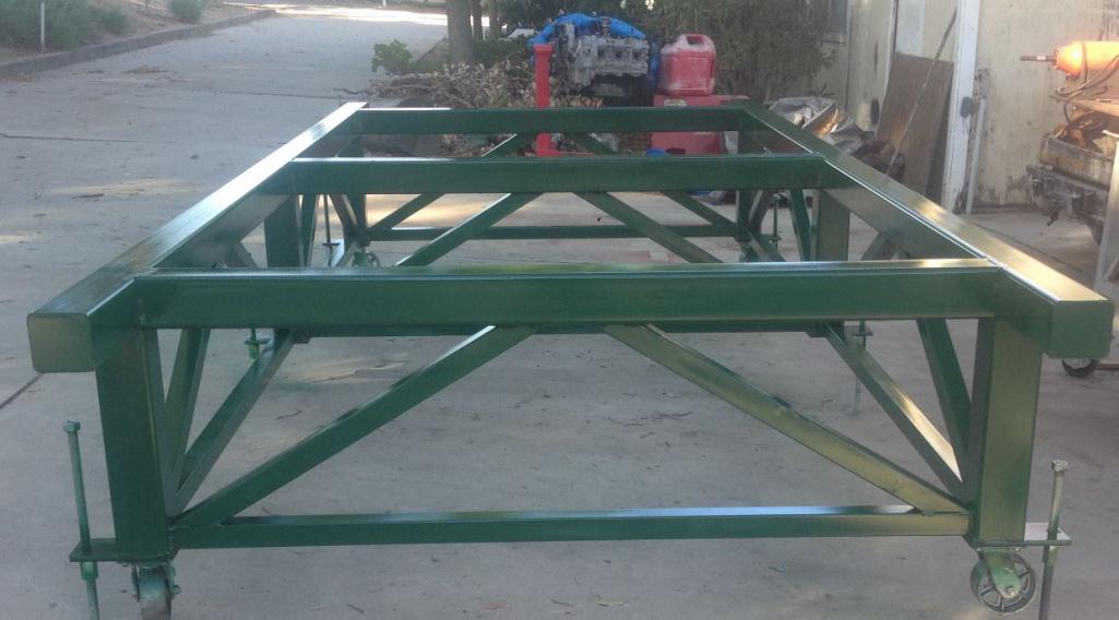
Well the material came in for the the chassis table.
These are the 2x2's that I will use for the webs
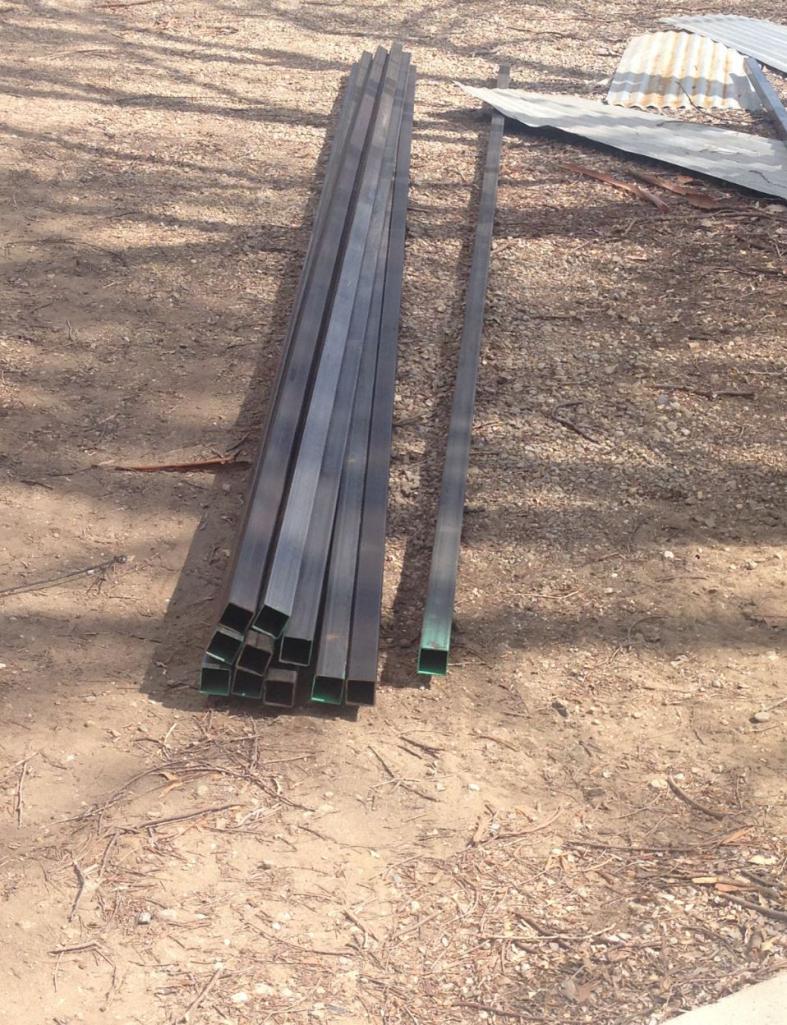
These are the 4x4's that I will use for the table platform and legs 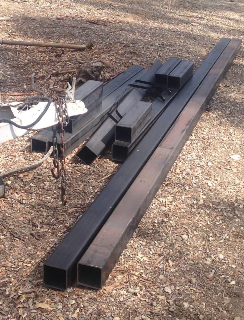
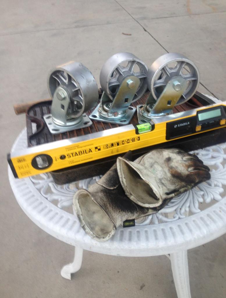
Here are the casters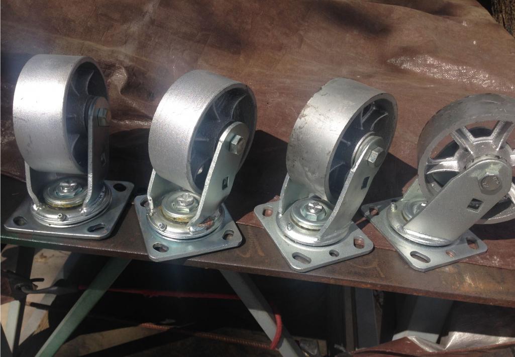
I also picked up some samples of Fine, Medium and Coarse recycled glass for the wet sandblasting. I'll try each to see which works better. Planning on blasting the suspension clean as well. I'll probably be using the fine for the aluminum blasting. I know guys use glass beads for aluminum but that is for delicate surfaces. The suspension is hardly a delicate surface so we will see how it pans out.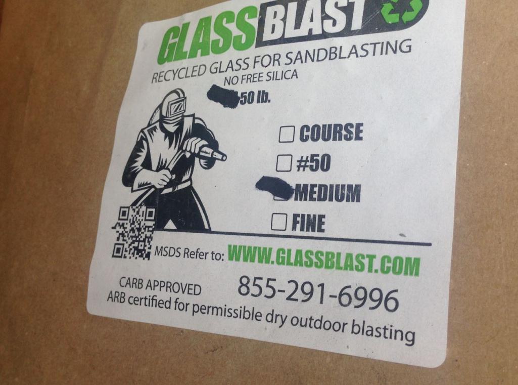
Posted by: 76-914 Jun 27 2016, 06:12 PM
Hey Rudy, I almost stopped by today but then I thought I should first ask if your around during the day. I might still be cleaning my engine Saturday. If I do finish cleaning it by then I'll start bolting the engine back together. I'll let you know when that begins.
That's a lot of metal there. But then again your connected in the welding biz, right?
Posted by: Curbandgutter Jun 27 2016, 06:35 PM
No more connections. We used to be in the industry 30 years ago. Now the only connection you need is the green kind. Damn steel is crazy expensive.  The material was around $1,200
  I'm usually in the office, so if you're by the area come on by.
Posted by: jd74914 Jun 27 2016, 07:00 PM
It uses thick tubing for the main hoops and thinner everywhere I can.
Cool! Figured you must be given the weight. I love 0.035 wall tubing!


No more connections. We used to be in the industry 30 years ago. Now the only connection you need is the green kind. Damn steel is crazy expensive.
The material was around $1,200 Ouch.
Can't wait to see the cart put together!
Posted by: Chris914n6 Jun 27 2016, 08:54 PM
Sorry, I'm a little late to the party
Looks like a NASCAR chassis, which would be a good reference.
Hard to see numbers with my eyes, but you will need bars at n14-n15 and in the front n13-n06 and n12-n07, or your first t-bone will be your last anything.
Posted by: Curbandgutter Jun 27 2016, 09:41 PM
I see what you mean but just think how much better this car will be than stock. Or even those that only are able to reinforce the longs. I think I'll be all right.
Posted by: Andyrew Jun 28 2016, 08:15 AM
So your not planning on gutting the chassis and putting this tube frame under it? Because that what it sounded like.
Posted by: Curbandgutter Jun 28 2016, 01:34 PM
No I'm not gutting the entire chassis but I am removing quite a bit from the rear. It will not have the rear strut towers, transmission mounts, engine support, rear suspension attachment points, rear lower trunk sheet metal and engine sheet metal wrap around.
Posted by: Curbandgutter Jul 9 2016, 08:14 AM
Well I've had to take a break to prepare for my son's wedding. I've taken little windows of time and worked on the chassis table thoug. It's almost complete just need to add the webs for the trusses and it's ready to mount the 996 on it first. I'm going to compile xyz coordinates for all of the suspension pick up points on the 996 and then transfer those coordinates onto the 914. That way I will keep the same suspension geometry that the factory had. I'll also be doing a twist test on the 996 and on the 914 pre-tube chassis and post tube-chassis. It will be interesting to note how much better the 914 chassis will be. I'll be taking all of the measurements with a laser plummet and a laser distance measure....stay tuned.
Attached thumbnail(s)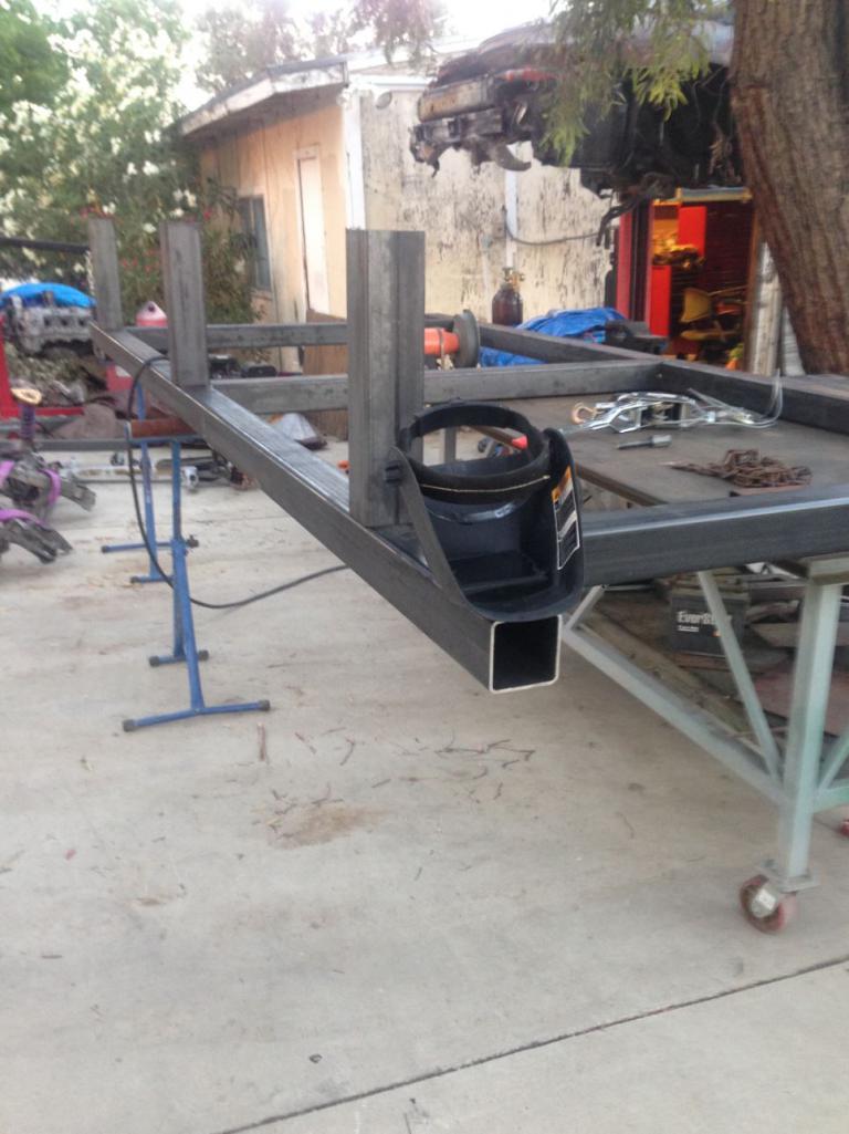
Posted by: jd74914 Jul 10 2016, 03:53 PM
I'll also be doing a twist test on the 996 and on the 914 pre-tube chassis and post tube-chassis. It will be interesting to note how much better the 914 chassis will be. I'll be taking all of the measurements with a laser plummet and a laser distance measure....stay tuned.
Sweet table! Very very nice!
You work fast! I've always wanted twist measurements; they should be really interesting. I've built solid "shocks" and twisted some formula cars. It's relatively easy to do and really neat to see how the results compare to FEA expectations. Unfortunately, our FEA was always a bit optimistic because it didn't include finite stiffnesses for all of the suspension joints.
It would be really interesting if you could twist it a few times after the tube frame with and without the engine, belly pan, etc. just to see how much incremental stiffness each piece adds.
Posted by: csdilligaf Jul 11 2016, 10:30 AM
Looks like your moving along well. I did a 914 with 993 suspension a long time ago with an LS6 and G50-52. I had the rotisserie and set up and a welding table For the suspension set up. With no room to store the stuff I got rid of it and now I have a new 914 project starting and was planning on making all the stuff again. As you know it is a huge investment and a lot of work. How about right after you get your chassis set up and of the table you do mine and recover some of the money you have in all this effort? I am just down the road in San Diego. Also here is another thread that you may have seen but its always good to see what others have going and see how they went about things.
http://www.914world.com/bbs2/index.php?showtopic=219539&st=0
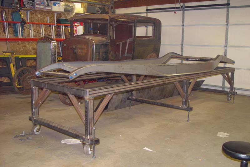
Looking good so far and I will be following the progress. And here is a shot of my 914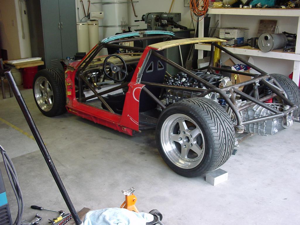
Posted by: Curbandgutter Jul 11 2016, 12:39 PM
CSDIILIGAF hey that 914 you did with the 993 suspension looks killer. Let's talk about using my rotisserie and frame table. I'm thinking that I can just rent it out to you for an extended period of time. That way your cost will be a fraction of the cost to make and I get a little back for my investment. PM me and give me your contact information I'm sure I can learn from someone who's done it already. Glad to have you commenting.
Posted by: Curbandgutter Jul 11 2016, 12:43 PM
JD74914 Instead of using the solid shock idea, which is a cool idea by the way, I was thinking of just setting the car up on 3 jack stands on the frame table, clamping them down and loading the wheel that doesn't have the jack stand under it. What do you think? Is there a better way? And yes I would like to test the twist under various conditions. We're just going to geek out and have fun with the numbers as well as the final product.
Posted by: Curbandgutter Jul 12 2016, 10:17 AM
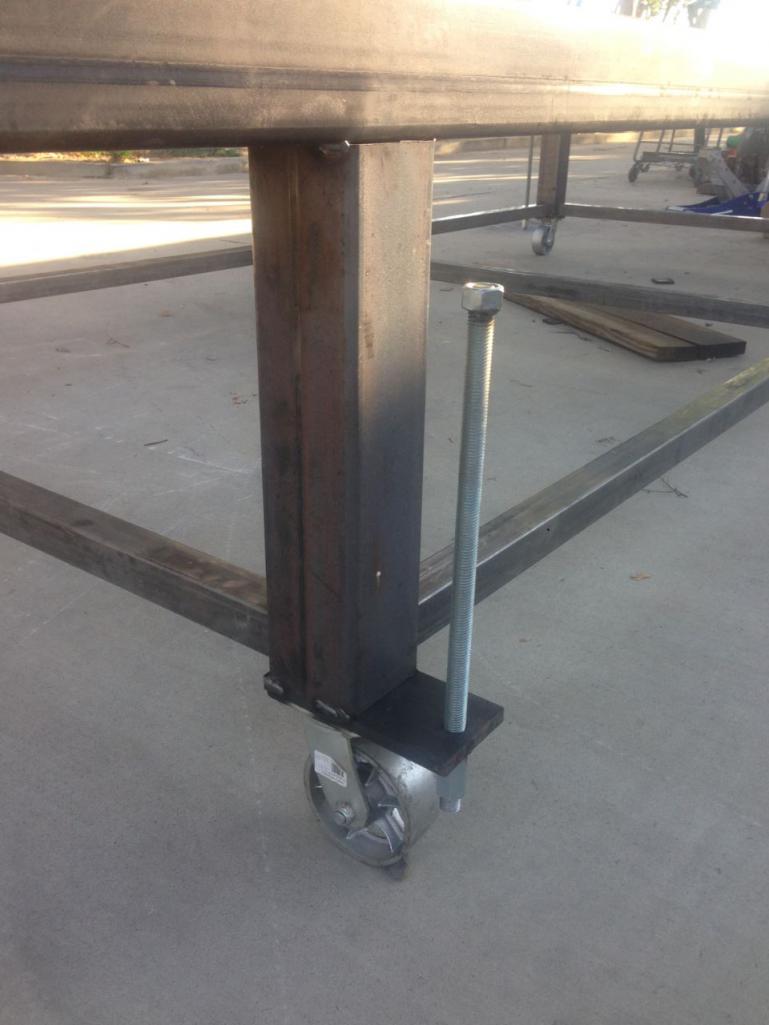
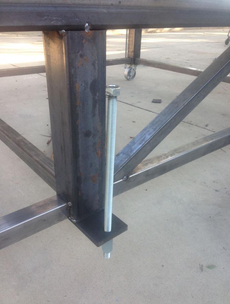
Does anyone have a good idea as to how to set up a jackstand with some form of a clamp to attach to bottom of longs? Taking all good suggestions. Bad ones  will be ridiculed . Just kidding of course but yeah let me know how you'v e done it or saw someone else do it. BTW no Mo-Clamps those are North of $200 each.
Posted by: Curbandgutter Jul 12 2016, 11:32 AM
I'm thinking of welding these to the end of a 2x2 post and using them instead of a jack stand. They are cheap and will do the job.
Attached image(s)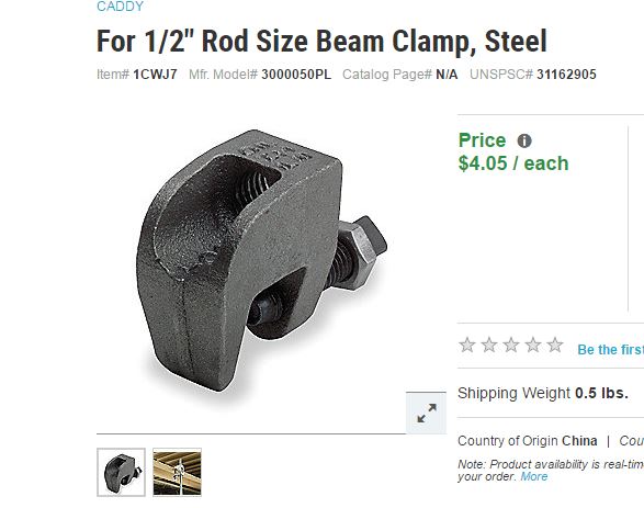
Posted by: 914forme Jul 12 2016, 11:38 AM
Weld a block of steel on one side, and tap for 2 3/8" bolts, add another on the others side and pinch the seem. Add knurling if you want between the jaws. Stands will need to be able to move as this design is not self centering.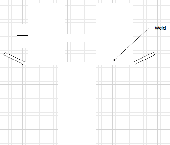
Our weld C clamps to the to of the jack stands.
Or weld a set of nuts to steel plates, weld steel plates under the rockers, bolt them to the fixture and grind them off once done.
Put wooden blocks under the rockers, drill holes through the rockers , wooden blocks, and fixture, use all thread, bolt it down.
I am guessing this is to do twist testing.
I would weld three legs down, and not use jack stands, as you will have to strap the car down anyways
Use weldable trailer rings onto the logs, put what ever you want under it, ratchet it down with welded rings on your fixture.
Trailer rings can be found that are rated for 18,000 of force per ring, and cost about 12.50 per ring plus shipping. Then some big straps, or chain. Or just load binders.
Posted by: 914forme Jul 12 2016, 11:41 AM
I'm thinking of welding these to the end of a 2x2 post and using them instead of a jack stand. They are cheap and will do the job.
Cast, thinking they will break at the bolt hole as you apply force diagonally to them.
Posted by: Curbandgutter Jul 12 2016, 12:23 PM
914FORME I like your idea about the trailer rings. Yes that will be necessary to be able to hold the car down for the twist test. I'm going to hold down into concrete with a wedge anchor. I do believe that the clamps that I have are rated for 750lbs. I'm going to give them a shot and see what happens.
Posted by: Curbandgutter Jul 13 2016, 10:41 AM
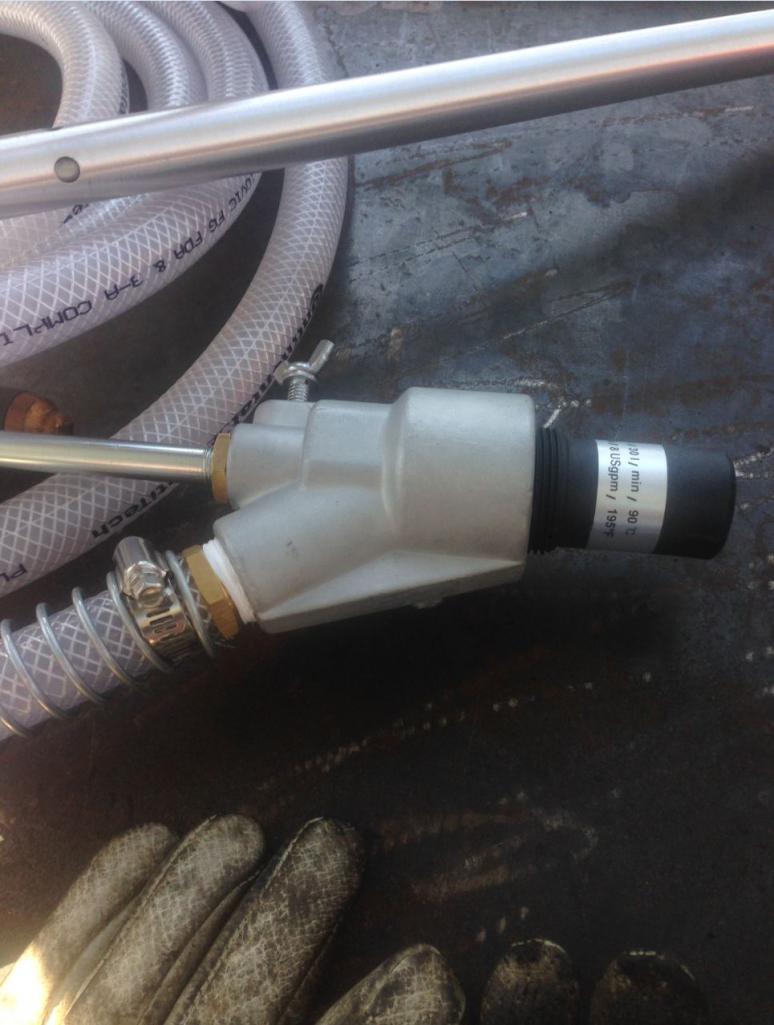
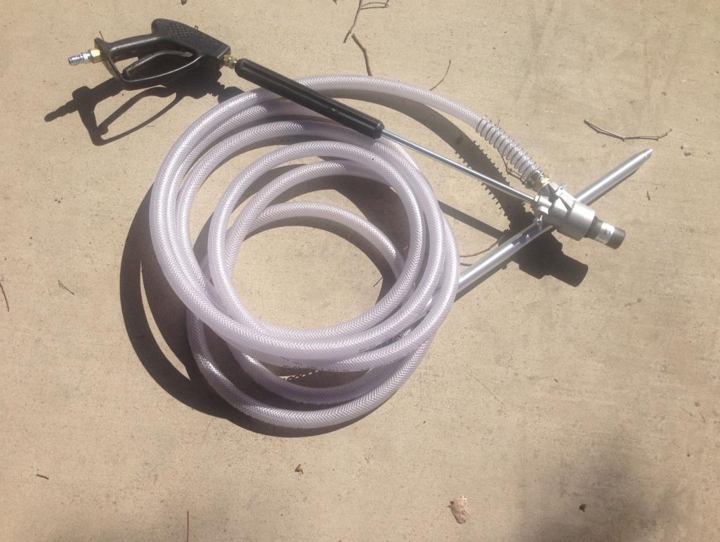
Well look at what came it today. The parts look to be first rate. Everything is USA made with the exception of a wand piece that is made in Germany. The company told me that they stand by their product and that if I'm not happy with the results that they will take it back. We will see. Supposedly they were able to do 1 sf per 1 min and 15 secs. Not bad at all.
Attached thumbnail(s)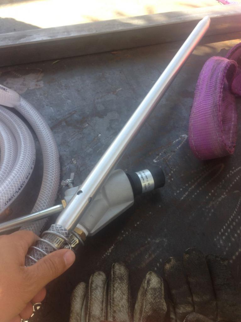
Posted by: Curbandgutter Jul 17 2016, 07:02 PM
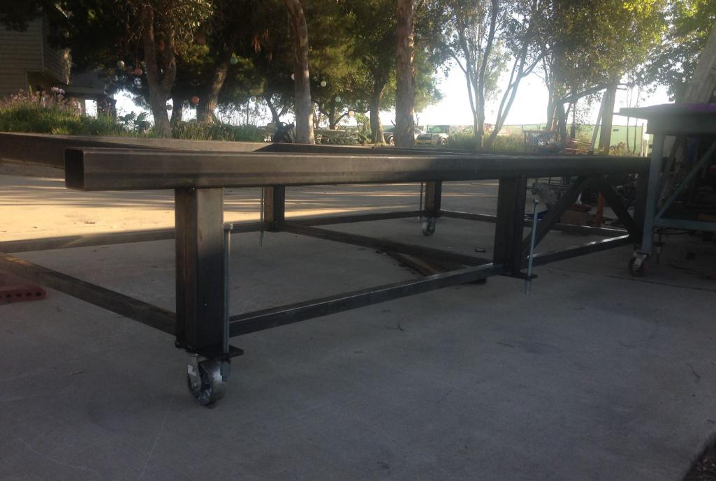
Well chassis table is complete. I measured it with a survey grade level and it is straight to 1/64th or 15 thousands of an inch. Now I can start about with actually working on the 914 rather than building all of the infrastructure (Rotisserie, Chassis Table, Sand Blast Cabinet). I guess I could have done it on the concrete floor and then have a twisted frame. But I couldn't live with myself. Rather, I'm doing it this way though because I just can't do this not knowing if my work is straight. However I have 3 weddings to attend in the next 2 months so my weekends are going to be used up in nonsense cause you know where I would rather be.
The order of work will be as follows.
First load 996 and measure and do a twist test.
second wet sand blast 914 on rotisserie
repair rust and epoxy primer
fourth put 914 on chassis table and do baseline twist test then start building tube chassis
Attached thumbnail(s)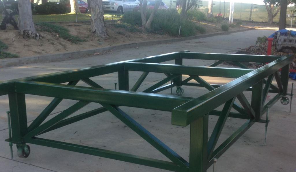
Posted by: mbseto Jul 18 2016, 09:17 AM
Wow. That's a sweet piece of work.
Posted by: Curbandgutter Jul 19 2016, 11:35 PM
Thanks bud.
Posted by: jd74914 Jul 20 2016, 06:35 AM
JD74914 Instead of using the solid shock idea, which is a cool idea by the way, I was thinking of just setting the car up on 3 jack stands on the frame table, clamping them down and loading the wheel that doesn't have the jack stand under it. What do you think? Is there a better way? And yes I would like to test the twist under various conditions. We're just going to geek out and have fun with the numbers as well as the final product.
It all depends on what you want to get out of it.
The clamping jack stands sound like a good idea you're most concerned with seeing changes in chassis stiffness and comparing to your FEA model. It's certainly easier than making solid shocks and hub adapters to clamp to the table and would produce really interesting data. I would love to see how close the FEA comes to actual!
On the other hand, it doesn't give you a great feeling on the stiffness of the whole system. I like to think of the chassis as a huge bracket which holds the suspension together; basically something that connects the dots. The most important reason to have a stiff chassis (besides impact safety which is a whole other design arena) is to remove an additional "spring" from your suspension. A flexy chassis can make suspension tuning difficult since it is sometimes tough to tune around that unknown spring. I did hub connections for my twist tests because I wanted hub-to-hub stiffness to understand the whole system. There can be a shocking amount of compliance in suspension mounts and components which you will miss if just doing a pure chassis twist. I have read that OEMs spend millions of dollars making sure mounting compliance is minimizes which is something the normal person isn't able to do.
Since you're keeping the stock suspension measurements, perhaps making hub adapters which bolt to the table wouldn't be so bad since you could use them multiple times and on both chassis? Just thinking out loud. I really do like the clamping jack idea too, the above were jut things to think about.
I'm thinking of welding these to the end of a 2x2 post and using them instead of a jack stand. They are cheap and will do the job.
Those should do the trick! They can hold a stupid amount on i-beams so I don't see why they wouldn't work on a flange.
Posted by: jd74914 Jul 20 2016, 06:35 AM
Your table is awesome BTW! I'm super jealous!
Posted by: Curbandgutter Jul 20 2016, 01:42 PM
JD74914 your responses are always so on the spot and I really do appreciate them. It is what makes these forums. With respect to the twist test incorporating the compliance in the bushings, tie rods, etc., I agree wholeheartedly. However, what I am trying to do is to get a chassis stiffness so that I know how to set up the springs. My current 996 suspension needs new bushings and ball joints, so checking it in this fashion will be counterproductive for my purposes. As you may already know, a rule of thumb is that if your suspension stiffness is more than 10% of the chassis stiffness, then a portion of the chassis will be flexing and absorbing the loads instead of it going into the springs and dampeners. This condition will give a horrible ride and will cause premature cracks in the chassis. I suspect that this happens quite often when people put a really stiff spring on a stock 914 chassis. As would be my case if I just used the springs off of a car that weighs 3274 lbs and placed them in a car that weighs 2100 lbs.
The chassis torsional stiffness that I will check will be:
1) The baseline existing 914;
2) The 914 with the longs stiffened;
3) The 914 with the steel roll cage;
4) The 996 in stock form (oh oh).
My intent is to help other teener's so that they can see if stiffening the longs truly works. And if so, how well? It will be very interesting to me and to others, I suspect.
I've been reading that a typical torsional stiffness for a sports car is somewhere between 10000 and 20000 ft-lbs/degree. Also, F1 cars are much higher than 20,000 ft-lbs/degree.
I hope to load the 996 on the chassis table this weekend. Them I'm off camping to Sequoia so I won't be updating for about one week.
BTW I really did like the way the chassis table turned out. It's nice to know that what you are basing everything off of is straight and true.
Posted by: Curbandgutter Jul 21 2016, 10:31 PM
Well the 996 is up on the chassis table. I was surprised to find that it had a twist of 1" in the frame. Wow I wonder how this thing handled? I wonder how it got that twist? I don't see evidence of a major wreck?
Attached thumbnail(s)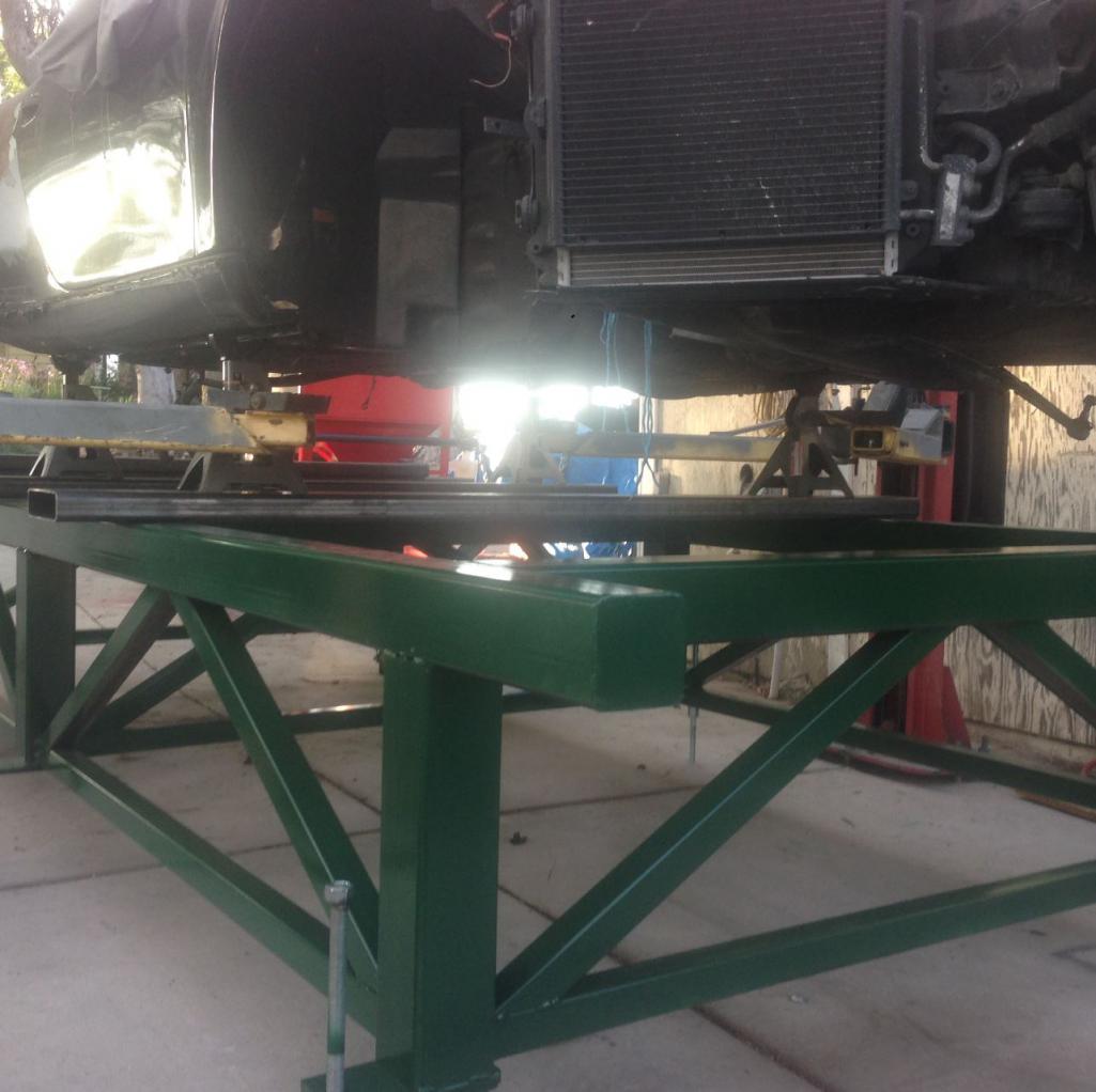
Posted by: 76-914 Jul 22 2016, 08:52 AM
Heat?
Posted by: Chris H. Jul 22 2016, 09:07 AM
Could be...that's a lot of twist. Check that German engineering on the radiator setup  . Every square inch used and you'd never know with the panels on.
Posted by: Curbandgutter Jul 22 2016, 10:06 AM
76-914 That has to be it. The fire was centered at the left rear corner and that's where the twist is. And here I am asking the stupid questions to the obvious answer.
Chris H. Yes I love the way they did it. Interesting to note that they are set up to exhaust UNDER THE CAR. I figured out a way to use all three in my design. I want the front trunk to be completely useful.
Posted by: jd74914 Jul 22 2016, 10:13 AM
Well the 996 is up on the chassis table. I was surprised to find that it had a twist of 1" in the frame...I wonder how it got that twist?
Frames do some pretty weird things when highly heated, especially if they haven't been previously stress relieved. Moving that far is pretty shocking.
However, what I am trying to do is to get a chassis stiffness so that I know how to set up the springs...As you may already know, a rule of thumb is that if your suspension stiffness is more than 10% of the chassis stiffness, then a portion of the chassis will be flexing and absorbing the loads instead of it going into the springs and dampeners. This condition will give a horrible ride and will cause premature cracks in the chassis. I suspect that this happens quite often when people put a really stiff spring on a stock 914 chassis. As would be my case if I just used the springs off of a car that weighs 3274 lbs and placed them in a car that weighs 2100 lbs.
Glad my comments are helpful in some way.
The 10% rule is good, you figure it keeps your chassis an order of magnitude stiffer so the end effect of its flexing is second order on the overall system. That said, I wouldn't base spring setup off chassis stiffness. What people normally do is decide on a suspension stiffness (say 1 deg/g) and then back out the wheel rate then spring rate, and then make sure their chassis is a stiff enough spring to be ignored.
Ride and handling doesn't have to be poor with a flexy chassis; think about how well some superkarts perform. From what I've read, some of the current F1000 cars also use the chassis stiffness as a tuning knob as well. In a 914 with stiff springs the flexible chassis is definitely bad because of fatigue failures like you noted.
My intent is to help other teener's so that they can see if stiffening the longs truly works. And if so, how well? It will be very interesting to me and to others, I suspect.
I'm very interested to see as well. In a rust-free car I'm not sure there is actually much benefit to long-stiffening with the Engman/Maddog doublers since the area moment of inertia increase is fairly low. On my car I made the longs deeper (well, on the side I'm finished with at least haha) to gain the h^3 advantage in bending stiffness.
I've been reading that a typical torsional stiffness for a sports car is somewhere between 1000 and 2000 ft-lbs/degree. Also, F1 cars can be as high as 20,000 ft-lbs/degree.
I believe these numbers are a little low. We always shot for at least 1500-2000 ft-lbs/deg on our lightly spring formula cars. Just to provide a Porsche comparison, here is some stiffness information I saved from somewhere a few years ago:
Porsche 996 Turbo (early): 9,957 ft-lbs/deg or 13,500 Nm/deg
Porsche 959: 9,515 ft-lbs/deg or 12,900 Nm/deg
Porsche Carrera GT: 19,177 ft-lbs/deg or 26,000Nm/degree
The Lotus Esprit is known for being pretty flexy and is said to be about 4315 ft-lbs/deg.
Current F1 cars I believe are currently much stiffer, though some may also be using their chassis as sprung members; the modeling you can do with $100M+ is pretty crazy.
The numbers above might not be correct since I can't remember the source, but give a little perspective. It should be really interesting to see what your 996 looks like!
Posted by: cwpeden Jul 22 2016, 10:38 AM
Well look at what came it today. The parts look to be first rate. Everything is USA made with the exception of a wand piece that is made in Germany. The company told me that they stand by their product and that if I'm not happy with the results that they will take it back. We will see. Supposedly they were able to do 1 sf per 1 min and 15 secs. Not bad at all.
Just make sure you keep the suction tube on top of the wand and dont point it up.
Once I got water in the media suction tube it was a bitch to get clean.
And the Pressure ratings for the washer to use is minimum. Mine was adequate ate 3500 psi and 4 gpm
Posted by: jd74914 Jul 22 2016, 11:58 AM
Bet the twist was from when the fire hose quenched the fire; the sudden temperature change probably sucked it in like you would use a torch and rag to suck in a body panel.
Posted by: Curbandgutter Jul 22 2016, 03:58 PM
The mystery twist has been discovered. Note to self make sure all jack stands are set to the same height. Frame is straight. This is great news since I need to measure the suspension cradle points on the 996 to transfer them to the 914.
Posted by: Curbandgutter Jul 22 2016, 04:15 PM
cwpeden Yes thanks for the heads up.
jd74914 i'm wondering how much benefit it would be to use the Engman and then add a strip of 1/8" flat stock on the top and bottom flange. That would add quite a bit more to the moment of inertia. The section modulus would be much better than the metal along the sides of the stiffener kit. I suspect that the Engman kit gives more rotational stiffness than bending stiffness though. We will see.
Posted by: Curbandgutter Jul 22 2016, 07:12 PM
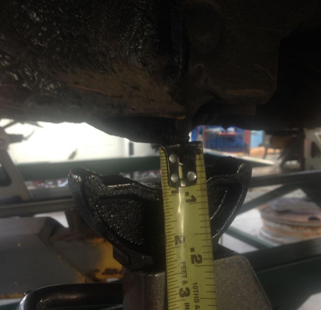
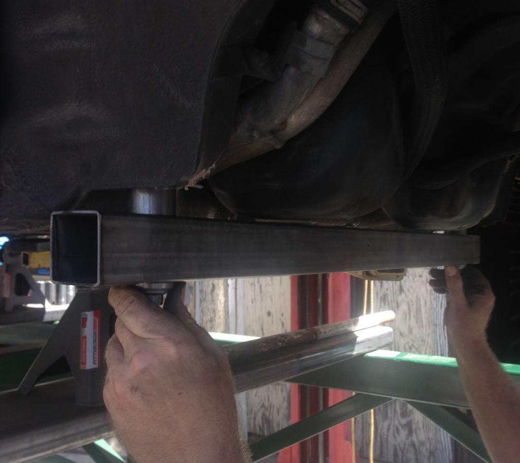
Well I finished measuring the 996 suspension cradle points. Here is how I did it.
First I laser plummet the bolt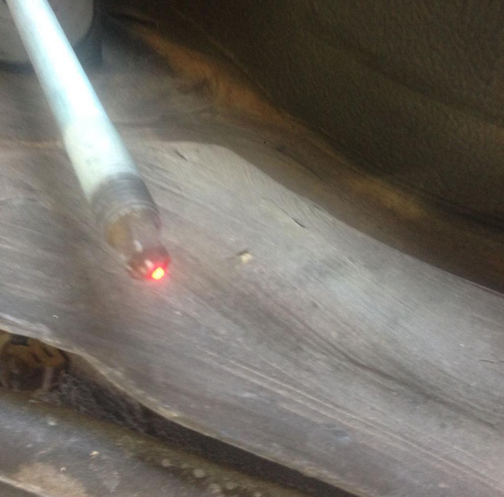
Then I transfer that mark to the ground floor like this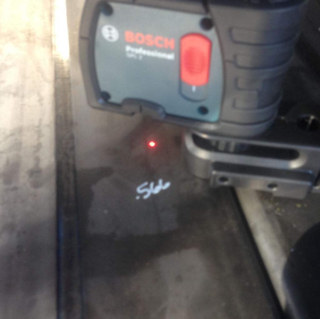
Then I measure horizontally like this
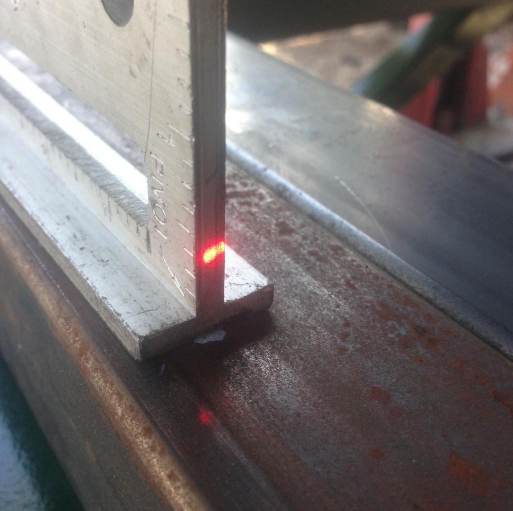
Then I measure vertically like this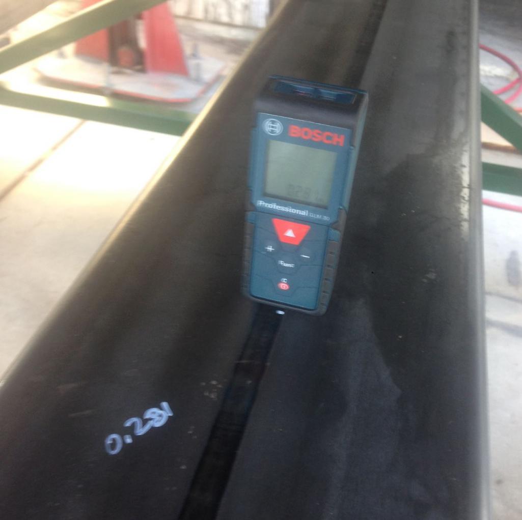
I also measure all of the diagonals and there you have it. All of the measurements needed to transfer to the 914.
Next step is twist test on 996. I'm out for a week camping so that will have to wait.
Posted by: My 914 Jul 22 2016, 07:34 PM
Have fun. Looking forward to your next update!
Posted by: Curbandgutter Aug 5 2016, 01:35 PM
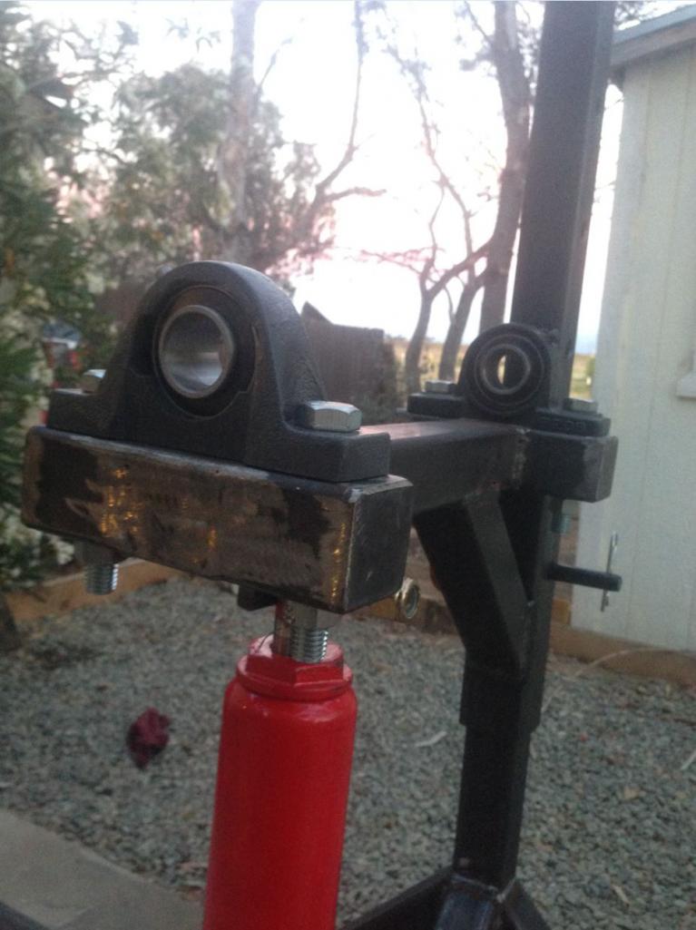
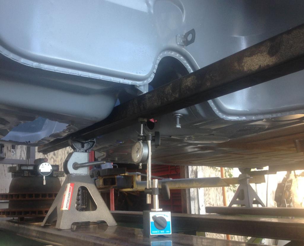
OK back on it. I'm out one week and I can't even find my project on the boards. It was soemthing like 6 pages deep. Anyway, got back from Sequoia and got to twisting the frame on the 996. Here are pictures of my contraption
This is the digital dial indicator that I used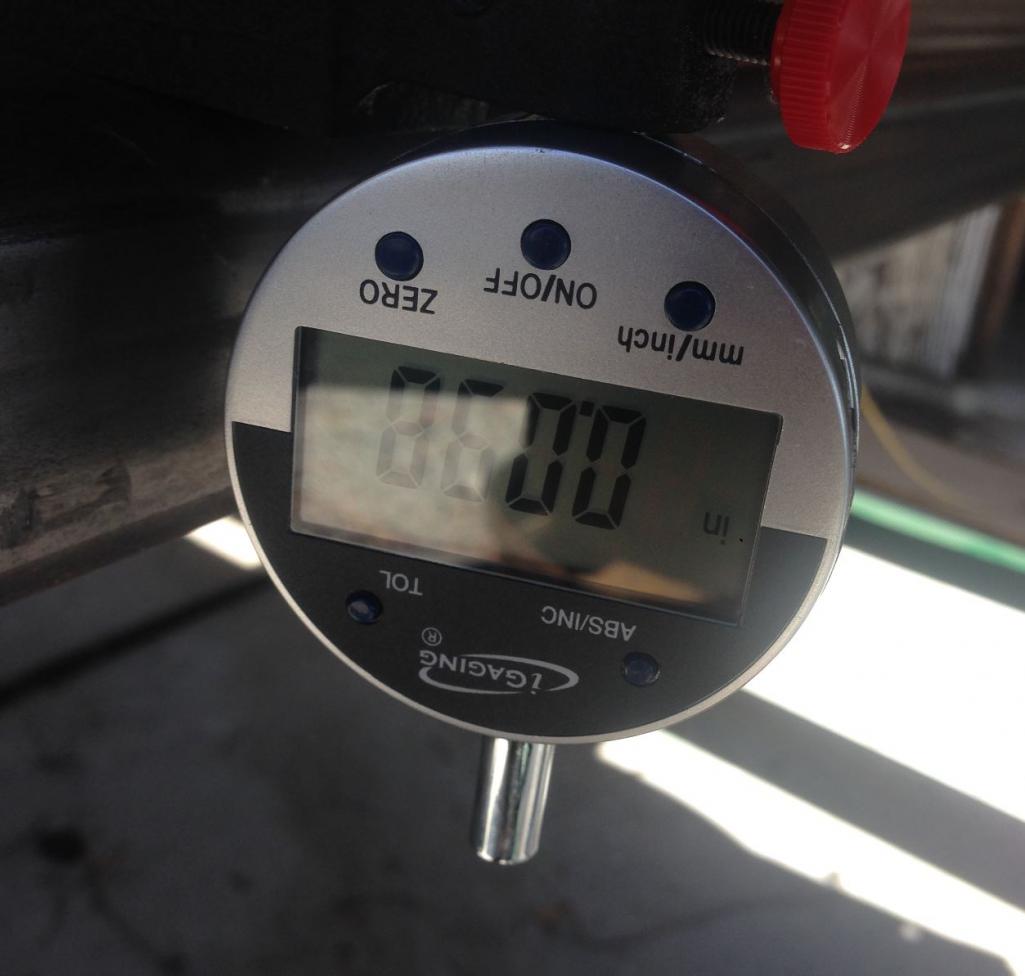
Here is how it triggers the dial indicator 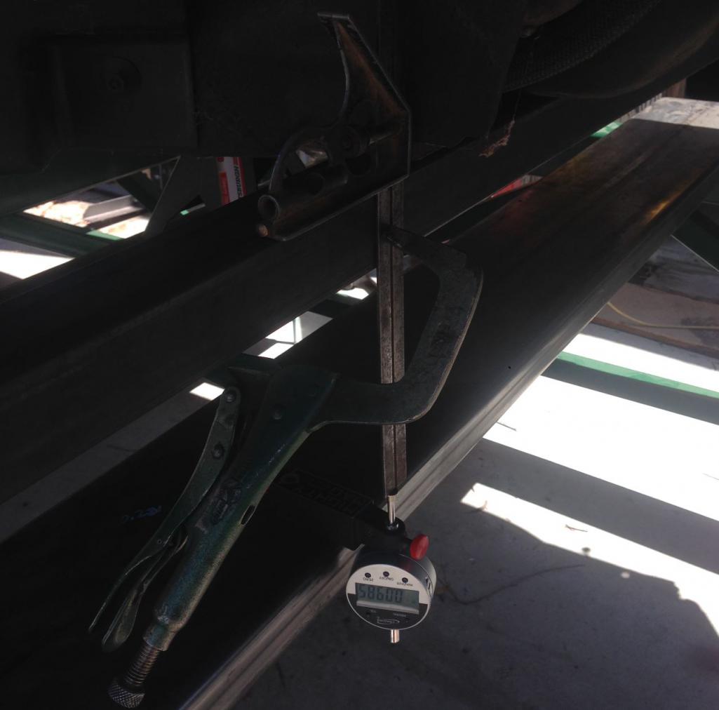
I added 100 lbs (2 -45's and a 10) at a distance of 11.375' This created 1137.5'-lbs of torque. Crazy deflection in the 2x2 but it was still only 50% stressed.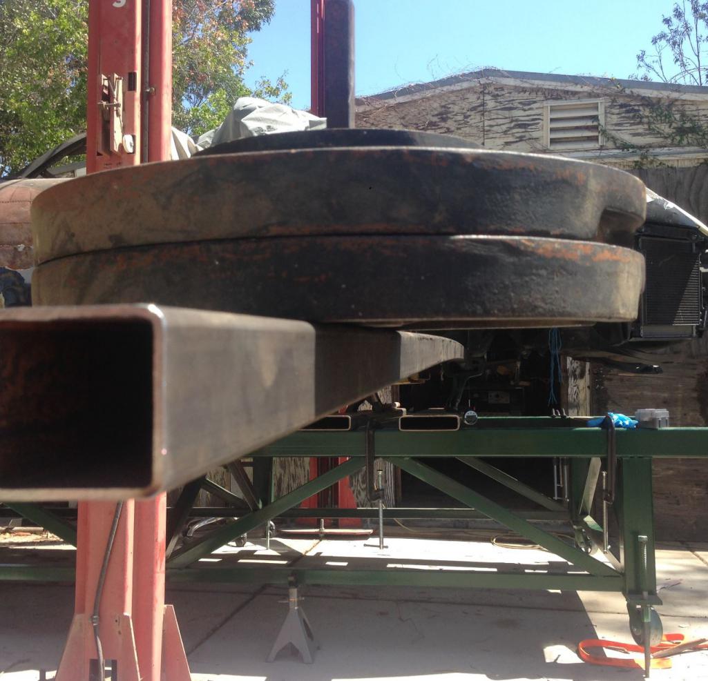
The final number for the convertible 996C4 is......4,568'#/Degree. Seems to be pretty flexible.
Posted by: Curbandgutter Aug 10 2016, 02:09 PM
Well this weekend member CSDILLIGAF and I will be making the nest for the suspension cradle. He's doing the same project so we'll work on the suspension and frame portions, and who knows what else? It's very helpful to have someone such as him working along side with me. According to my count this will be his 3rd successful Frankenstein transplant. He's the one that did a full 993 suspension on a tube chassis 914. From what I understand his 914 currently races in a very famous race and does very well. I love these 914's they are an incredible platform to work with.
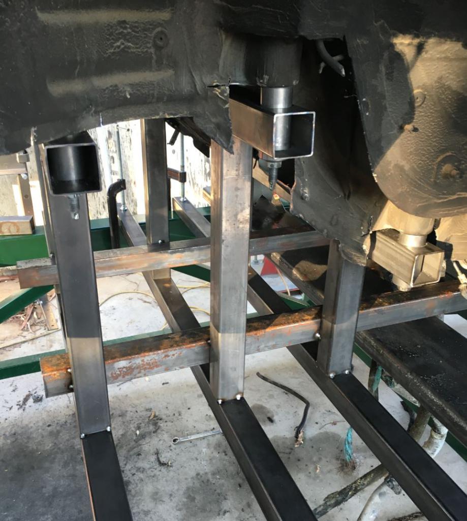
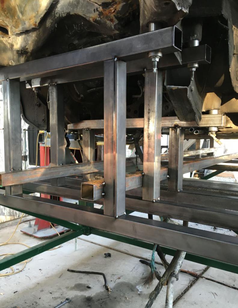
Posted by: Curbandgutter Aug 13 2016, 07:57 PM
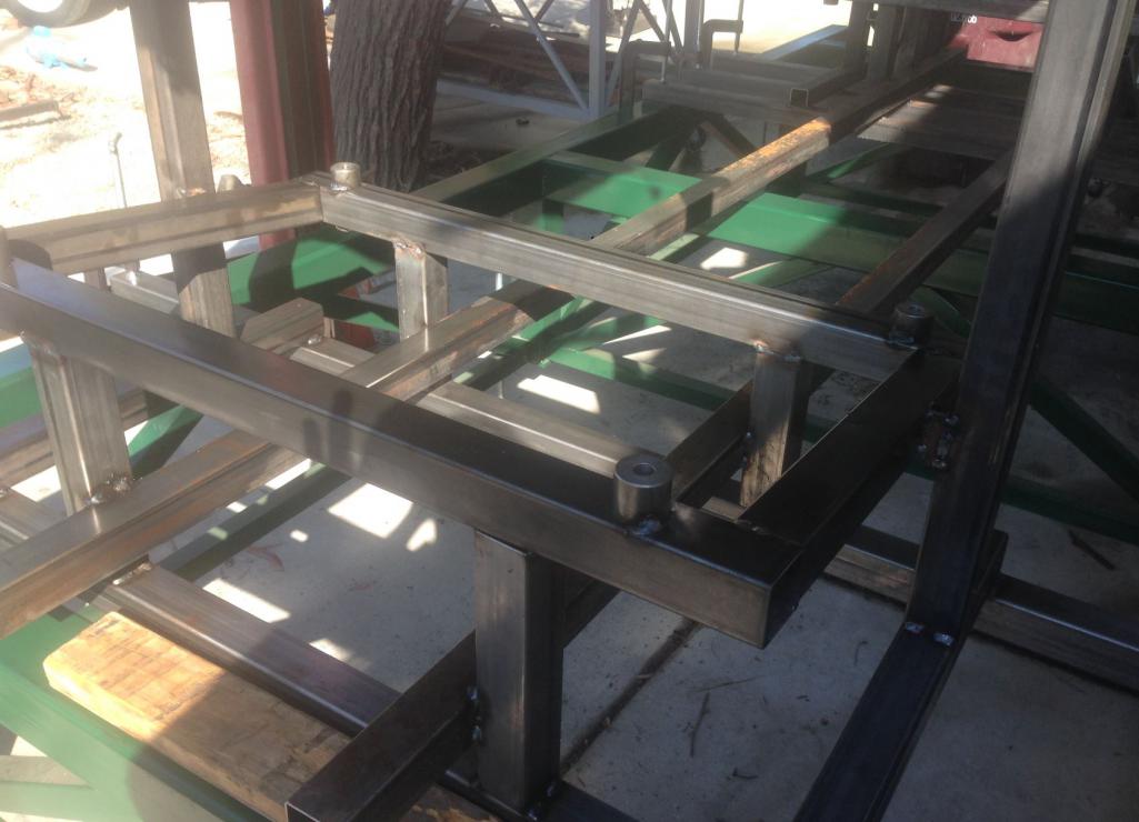
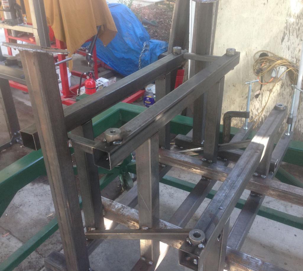
Well here is the suspension nest or fixture as some call it. CSDilligaf came over and we hit it for 8 hours straight. Only stopped of for a carnitas burrito, with rice and beans and all the fixins. Couldn't have done it so fast without CSFilligaf. It was nice to bounce ideas off each other as we put this thing together. Thank you for the input, work and the sweet bushings that you machined. Really pleased with the way it's coming out. It is almost complete as we only need to add the strut tower locations and finish welding a couple of more beads and cross bracing. After this, I can start building the frame for the 914 with this suspension nest centered and elevated within the shell of the 914. Enjoy the pics.
Attached thumbnail(s)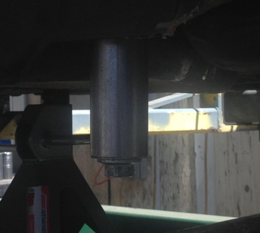
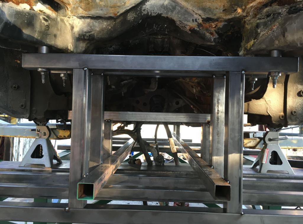
Attached image(s)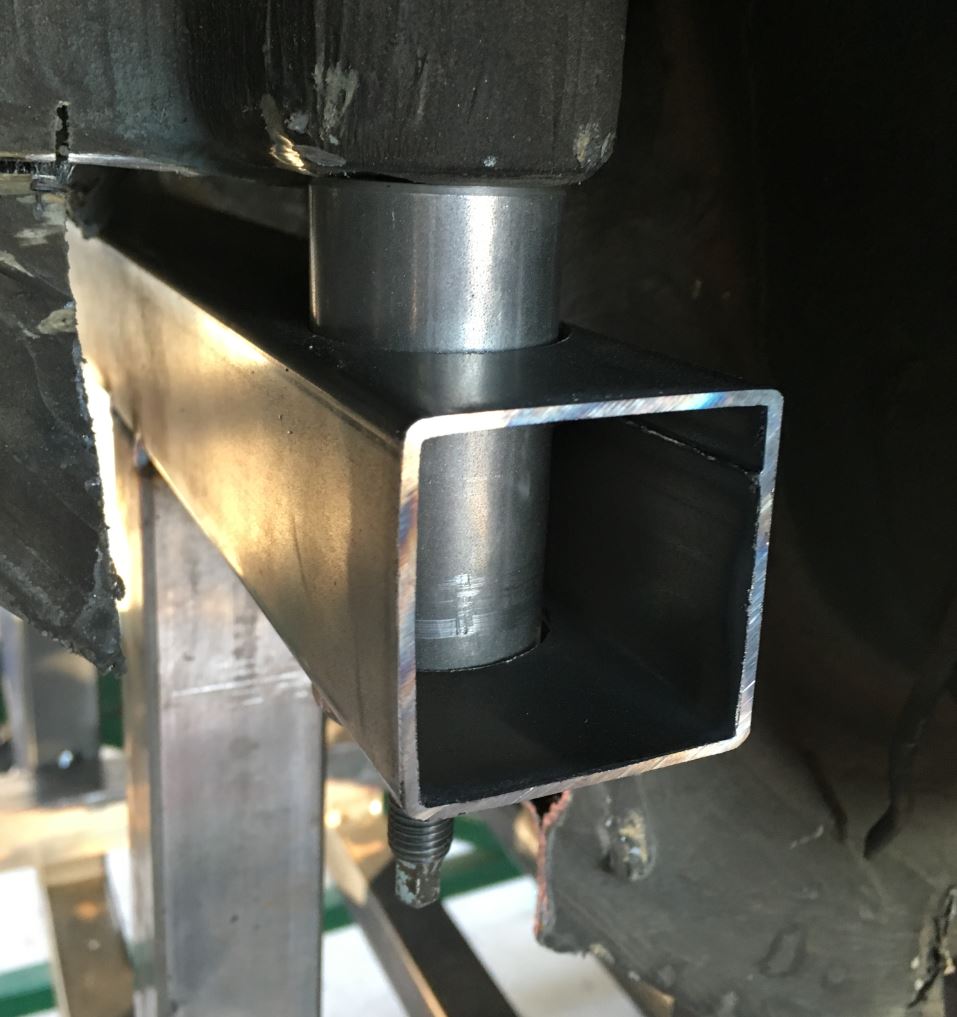
Posted by: 914forme Aug 14 2016, 07:35 AM
Posted by: csdilligaf Aug 14 2016, 08:00 AM
Rudy, I really enjoyed myself working at your place. A little on the hot side and sweat my butt off but we sure hung in there. We got a lot of work done. Cant wait until the next stage of the build.
Posted by: NS914 Aug 15 2016, 10:16 AM
Subscribed and really enjoying this build....truthfully, I can read some of this but I sure as heck don't understand it...amazing work though and really interesting to see what someone (who clearly has an amazing background) can do with a car in their backyard...speechless actually and thanks for posting. Grant
Posted by: Curbandgutter Aug 16 2016, 11:49 AM
NS914 Thank you for your kind words. This build would have been very difficult 20 years ago due to knowledge being bottled up in some guru's head and not being able to be shared with no more than those within physical proximity. However, now with the "information superhighway", all we have to do is to research online and fill in our void areas with the specialized knowledge of others. This truly is a great time to be doing projects such as this since one can pull from the collective knowledge of the online community. Trust me we all learn from each other.
Back to the project now. I'm tying in the strut towers today and will have pictures up later. After that....the suspension fixture will be complete. Next step will be to strip the 914 and epoxy primer. I'm using the epoxy primer from a company called SPI. Then pull the 996 of the chassis table and insert 914 onto suspension fixture. Then the fun will start. The rotisserie, the chassis table and suspension fixture was only preparation to work the on the 914.
Posted by: dakotaewing Aug 16 2016, 01:28 PM
NS914 Thank you for your kind words. This build would have been very difficult 20 years ago due to knowledge being bottled up in some guru's head and not being able to be shared with no more than those within physical proximity. However, now with the "information superhighway", all we have to do is to research online and fill in our void areas with the specialized knowledge of others. This truly is a great time to be doing projects such as this since one can pull from the collective knowledge of the online community. Trust me we all learn from each other.
Back to the project now. I'm tying in the strut towers today and will have pictures up later. After that....the suspension fixture will be complete. Next step will be to strip the 914 and epoxy primer. I'm using the epoxy primer from a company called SPI. Then pull the 996 of the chassis table and insert 914 onto suspension fixture. Then the fun will start. The rotisserie, the chassis table and suspension fixture was only preparation to work the on the 914.
The SPI epoxy is good stuff ! My project was sprayed in 2009 with it and has served me well. The project is still in the garage, waiting for me to finish the paint job -
Are you going to use their base and clears as well?
Posted by: csdilligaf Aug 17 2016, 07:20 AM
It will be awesome to see the 914 up on the table and start the whole process of joining the 996 suspension into a 914 chassis. I will make another trip up to help. Be sure to post about how the blasting of the 914 goes.
Posted by: Curbandgutter Aug 17 2016, 12:22 PM
DAKOTAEWING yes I will be using all SPI material. From the research that I've made they seem to be the HOT TICKET.
CSDILLIGAF yep I'll call you when I get ready to place the 914 in THE NEST . That will be monumental.
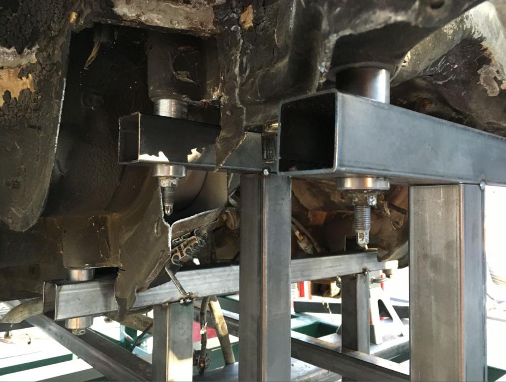
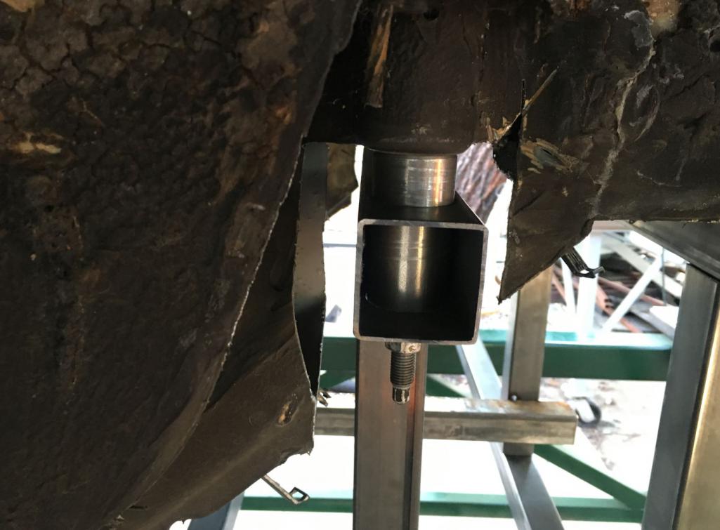
Attached are pictures of how I located and tied the strut locations to THE NEST. Man we had to do alot of  of the 996 frame to get these locations.
Here is the space age template for the strut towers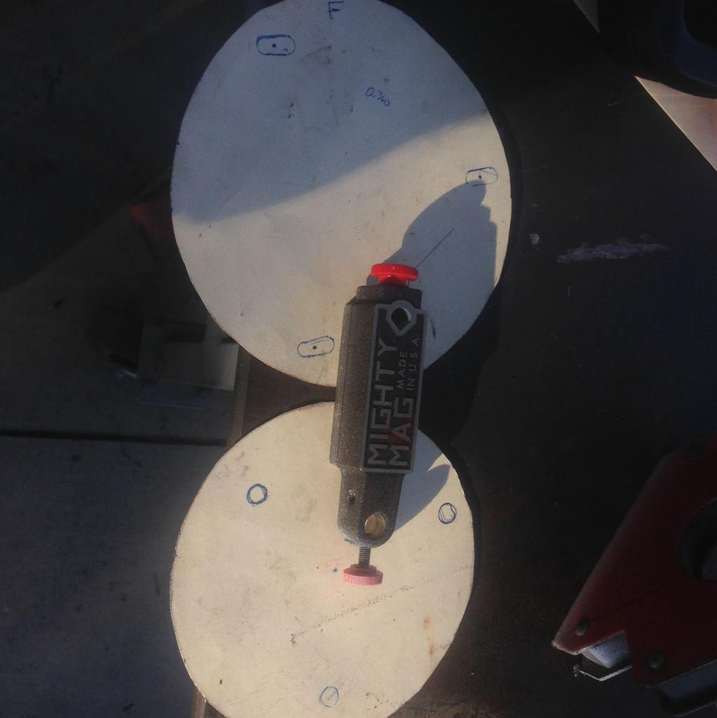
Here is the space age marking of said templates 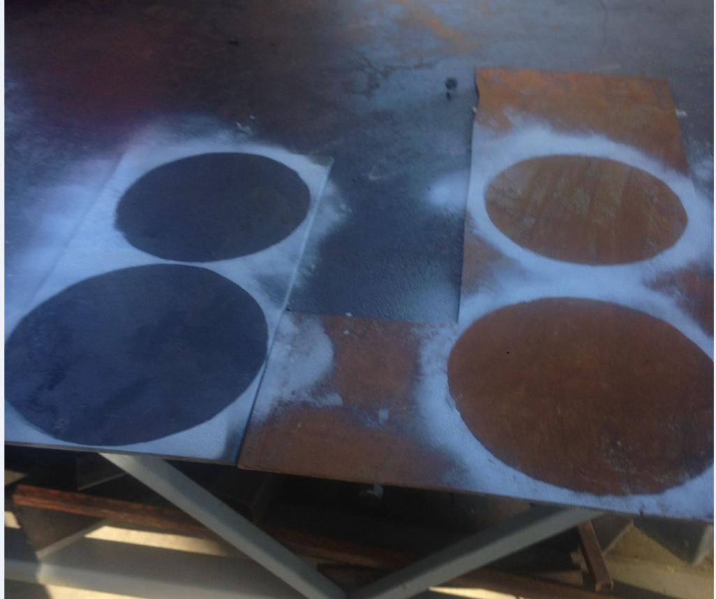
This is what was used to cut 
Here it is in place 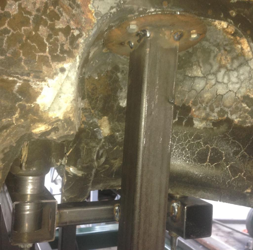
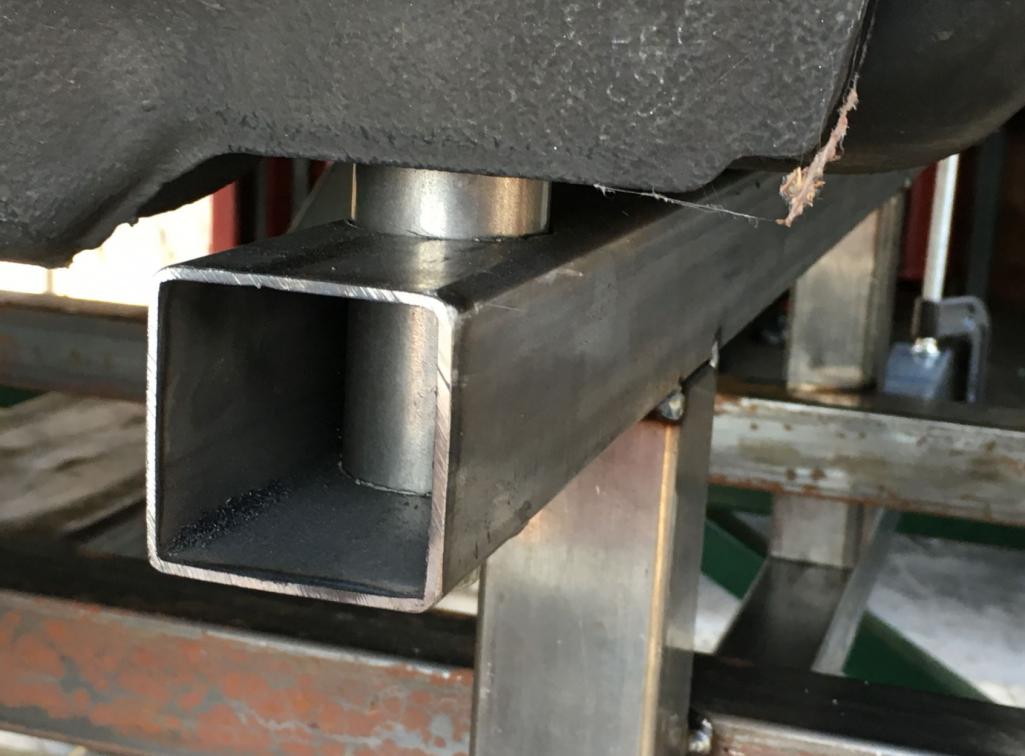
Posted by: Curbandgutter Aug 23 2016, 10:08 AM
Well the suspension nest is complete and the 996 can be pulled off and put away.
Attached thumbnail(s)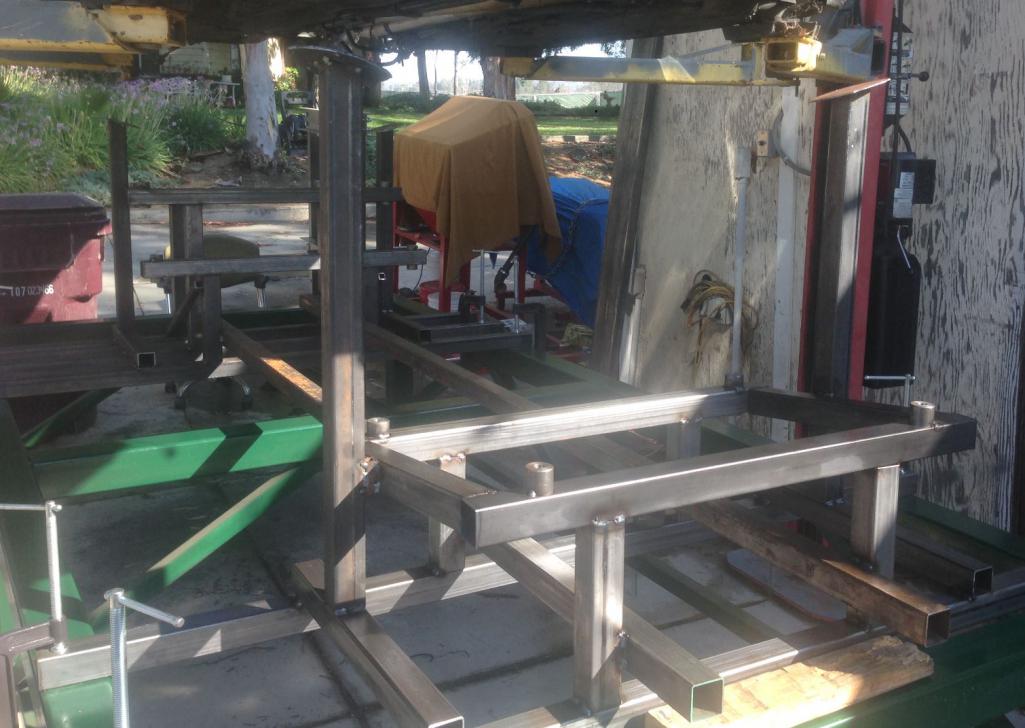
Posted by: csdilligaf Aug 23 2016, 12:40 PM
Very Cool Rudy! Looks great, You've come a long way so far. The fun part is about to begin.
Posted by: Curbandgutter Aug 26 2016, 11:57 AM
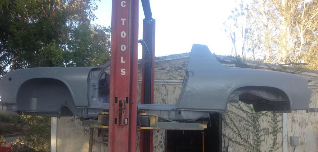
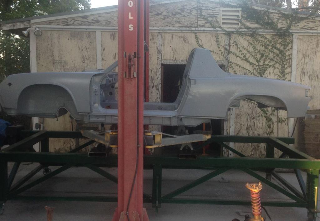
Well the 996 is finally off the nest and no longer needed. Big milestone for me. I'm blasting the 914 this weekend and epoxy primering it.
Attached thumbnail(s)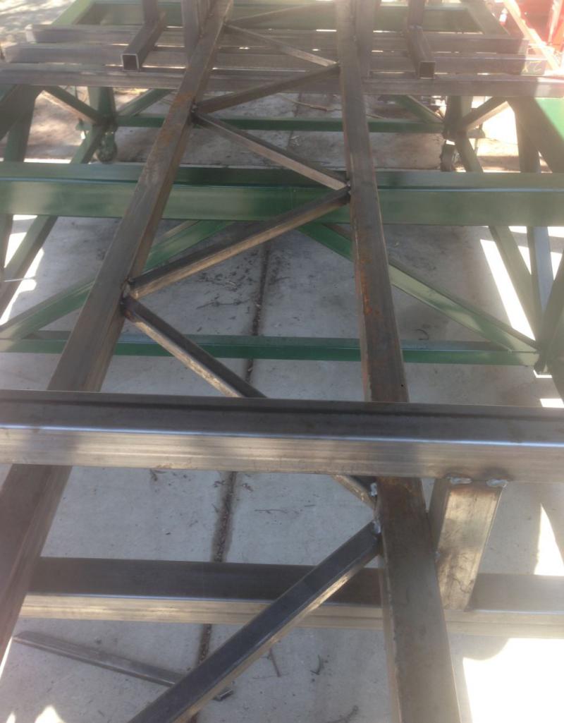
Posted by: Curbandgutter Aug 29 2016, 12:26 PM
Well I started to wet blast the 914 and I ran out of sand. I've already used 2000 LBS. I think that I can get away with another 5 bags but I'll just get 10 just in case. Sand is cheap. Here is the video
https://youtu.be/RZ0oQxO59Y8
Posted by: pete Aug 29 2016, 12:40 PM
Well I started to wet blast the 914 and I ran out of sand. I've already used 2000 LBS. I think that I can get away with another 5 bags but I'll just get 10 just in case. Sand is cheap. Here is the video
https://youtu.be/RZ0oQxO59Y8
Hi, what set up are you using for wet blasting? I think I bought a similar set up: http://www.globalindustrial.com/p/outdoor-grounds-maintenance/pressure-washers/accessories/mtm-5000-psi-industrial-sand-blast-kit?infoParam.campaignId=T9F&gclid=COCzkNyi584CFcFbhgod4vUAMA
but I am definitely not getting the same pressure you are. I'm using a Costco 2,600PSI pressure washer so its probably more like 2,000psi (maybe) and I was having a lot of trouble with clogged lines. If I kept blasting and had someone making sure the pick up tube was always in sand and the pick up hose flowing down to the nozzle then it was ok. The minute I stopped to looked at my progress the sand would clog though.
Posted by: Curbandgutter Aug 29 2016, 01:52 PM
I'm using the Power Eagle set up. I blew by 2000 lbs of sand and no clog ever. I would dump 300 lbs (3 bags) of sand into a 35 gal trash container. Then I covered to keep the sand dry and clean of debris. I absolutely loved the performance. It wasn't cheap though. It cost $300. However, it did not clog once and I even turned it upside down. I am using a Dewalt 4200 PIS with 4 GPM. Sand is #30 silica sand.
Posted by: pete Aug 29 2016, 01:58 PM
I'm using the Power Eagle set up. I blew by 2000 lbs of sand and no clog ever. I would dump 300 lbs (3 bags) of sand into a 35 gal trash container. Then I covered to keep the sand dry and clean of debris. I absolutely loved the performance. It wasn't cheap though. It cost $300. However, it did not clog once and I even turned it upside down. I am using a Dewalt 4200 PIS with 4 GPM. Sand is #30 silica sand.
Thanks for the info. Yeah I think my nozzle is basically the same. I think the bigger pressure washer is key though. I'll try renting a bigger one when I get going again. Your Build looks great! I'm going the V8 route as well.
Posted by: csdilligaf Aug 29 2016, 03:17 PM
WOW! that Baby sure does the job.
Posted by: Curbandgutter Aug 29 2016, 04:23 PM
WOW! that Baby sure does the job.
Yes I was very happy with the performance. It will probably take another 2 hours. For a total of 7 hours and 2500 lbs of sand. Let me tell you though it is the messiest job you will ever do. It's best to do in an open field or in an enclosure. Definitely not something to do in your shop or in your driveway. I'm on 2 1/2 acres with no neighbors so it worked out for me.
Posted by: Curbandgutter Sep 3 2016, 04:31 PM
Well I finished epoxy primering the 914. The next step will be to mount onto the chassis table, take some twist measurements and start building the tube chassis. I will be replacing the entire floor. It's just too banged up and rusty to mess with. I will also be removing almost the entire rear half. The entire rear half will be in steel tube and rear half of the body will be bolted to the tube chassis. Found 4 rust areas that I will need to repair. That can wait as they are not in the way of the tube chassis.
Attached thumbnail(s)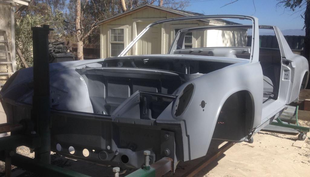
Posted by: Curbandgutter Sep 10 2016, 06:33 PM
Well CSDilligaf came over today and we did the twist testing on the 914. The final numbers are in! The 996 C4 Cabriolet has stiffness of 4,568 '#/Degree. The 914 has a stiffness of 3,326 '#/Degree. So the 996 C4 Cabriolet is 37% stiffer in torsion than the 914. Makes sense, since you'd think that the newer Porsche should be stiffer than the 914, which was built with technology of the 60's. The next step is to place the 914 on the suspension nest and start building the tube frame. I was thinking of stiffening the longs with the Engmann kit, but I'm steering away from that. I will be stiffening the "longs" with a truss system built inside of the longs. That will be the first order of work. I will twist test again at that point and see what improvement we get.
Attached thumbnail(s)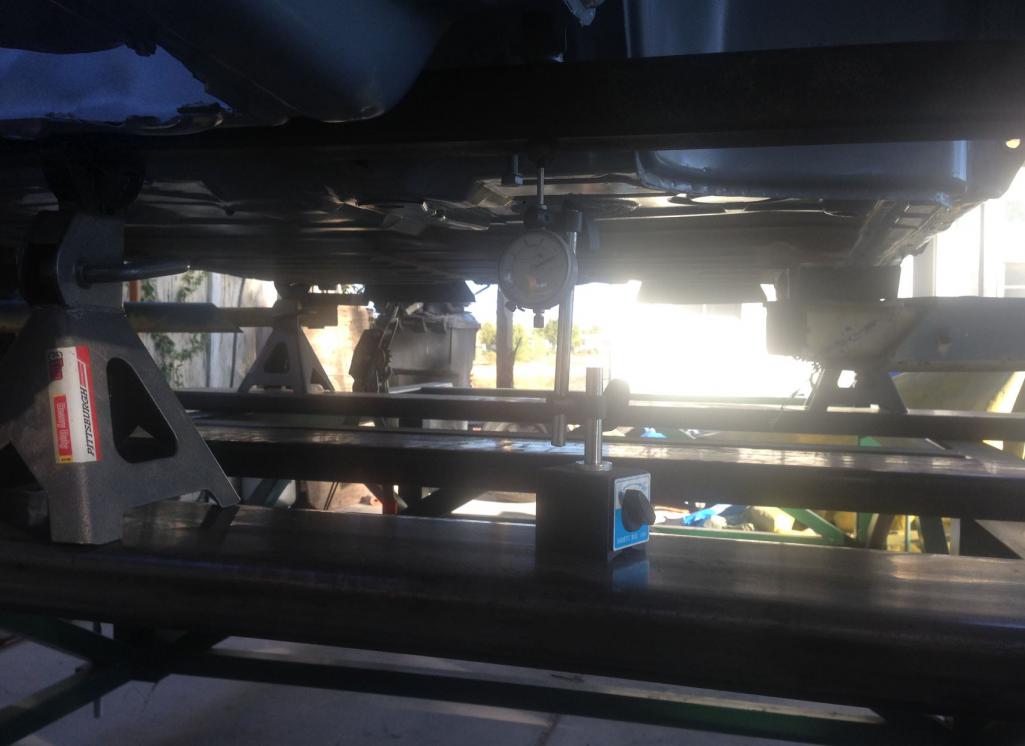
Posted by: Andyrew Sep 10 2016, 08:01 PM
Why not give Engman a call and see if they will give you a kit to test with? I know if I was the manufacturer I would want to know what it did. Im sure he would give you a kit for free.... Most of us run the Engman kit and I for one am curious what real world difference it makes.
Posted by: Mike Bellis Sep 10 2016, 08:17 PM
Why not give Engman a call and see if they will give you a kit to test with? I know if I was the manufacturer I would want to know what it did. Im sure he would give you a kit for free.... Most of us run the Engman kit and I for one am curious what real world difference it makes.
Engman passed away...

Posted by: Curbandgutter Sep 11 2016, 03:15 PM
Wow that is sad to hear that Engman passed away. My condolences to his family.
As far as trying to see how well the Engman works (inside reinforcing) or Mayeur (outside reinforcing), bring your car over and we will twist it. Have to wait until I'm done with my car though. I'm in Murrieta Ca. It's about 1 hour north of San Diego and about 1:15 hours South of Los Angeles. PM me and we can discuss.
Posted by: Curbandgutter Sep 12 2016, 05:42 PM
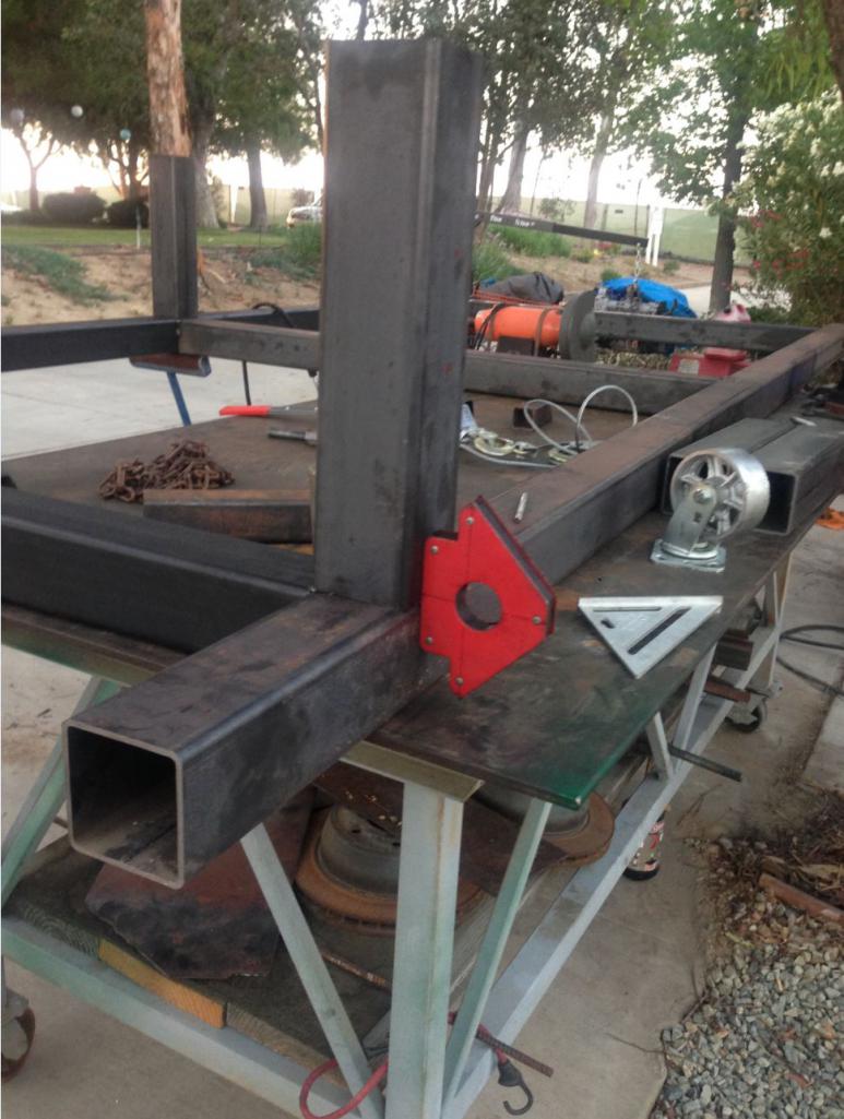
Steel for chassis is coming in tomorrow. Going to build 6 turnbuckle braces to square up driver compartment before I get started. Should have nest in place this week as well. Let the chassis building begin.
Posted by: Curbandgutter Sep 16 2016, 07:50 AM
Well..........this officially marks the point of no return. Up to this point the 914 could have easily been turned into a restored stock......but now the fork in the road has been reached and I'm taking the "road less traveled". Started to cut up the engine and transmission well. Planning on installing nest tomorrow and will start with "upgrading" the longs first. I couldn't believe how much sand was in the longs. The left long had about a large coffee can of sand in it. I don't know where it could come from since the left did not have any corrosion. On the other hand the right long, the one with the hell hole, that one only had about a up of sand in it? You would expect it to be the other way around. Also, the left long had some fibrous cotton like material inside of it? Anybody have an idea what this is?
Attached thumbnail(s)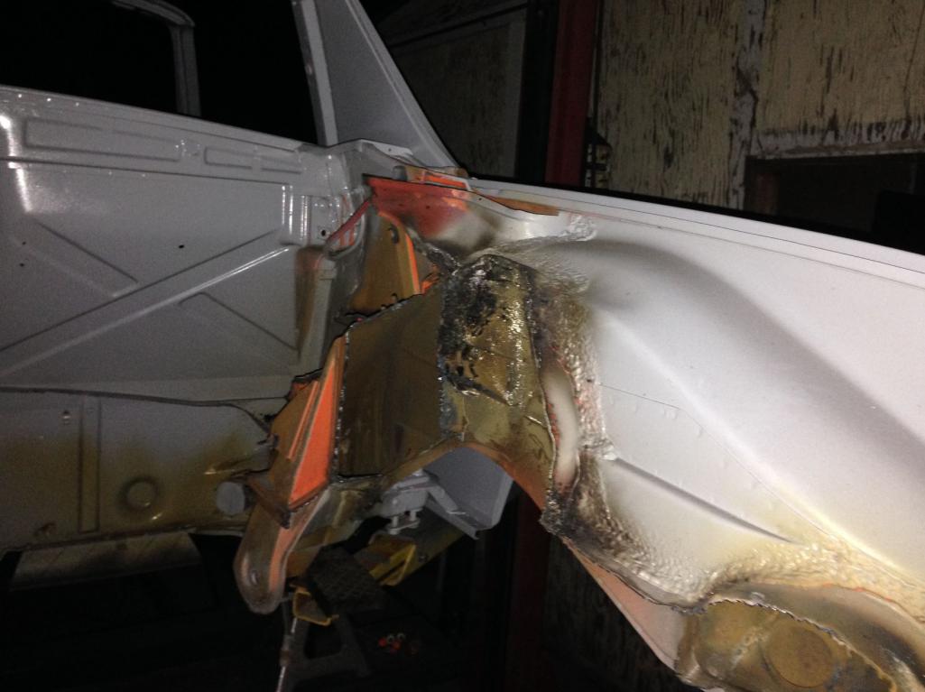
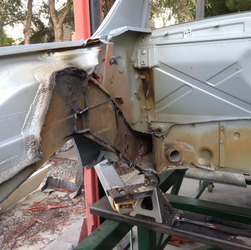
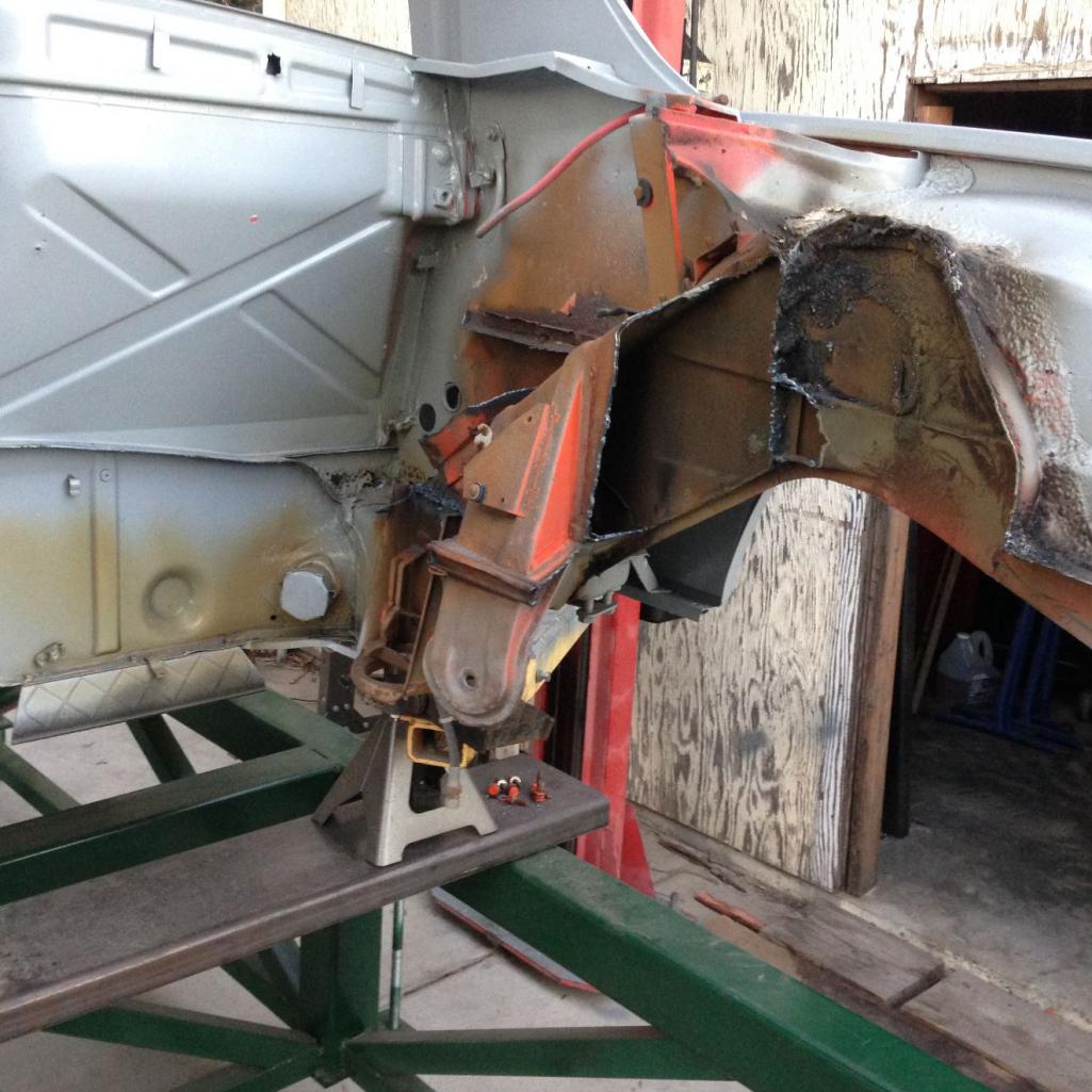
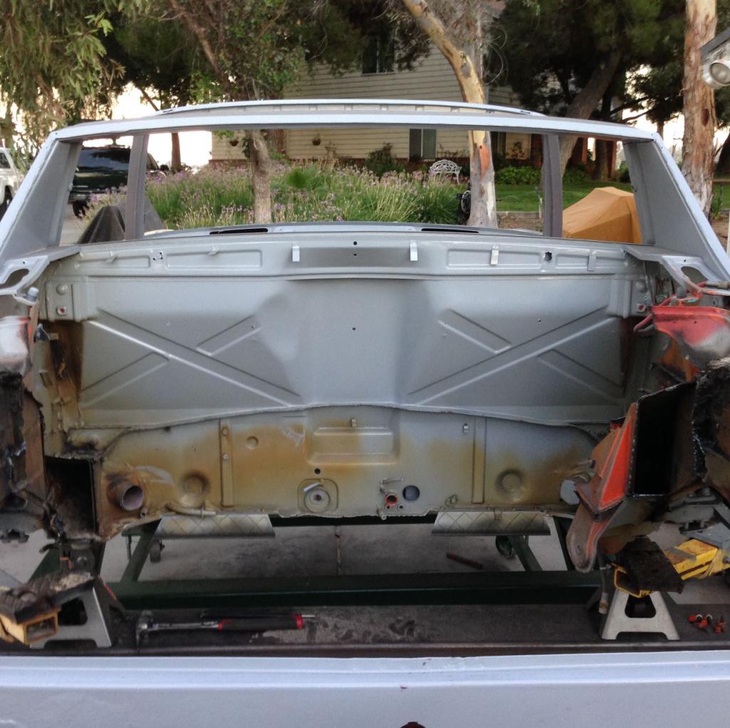
Posted by: veekry9 Sep 16 2016, 08:18 AM
So,it's true then,all 914s rust from the inside out,as well as outside in!
They get it from all sides,every direction.
The material found inside is the stuff that absorbs the moisture,inflicting it on the unprotected steel.
The horror.
That cutting and chopping with the plasma is what I've had in mind for the minor stretch,to accommodate the longer engines.
This is getting interesting.Kudos.

/
Posted by: Curbandgutter Sep 16 2016, 08:32 AM
Thanks veekry9. After seeing the "surface" rust inside of the longs......I would encourage everyone to stick some of the Eastwood internal frame coating inside. These things rust from the inside out as well as the outside in.
Posted by: andys Sep 16 2016, 10:15 AM
So,it's true then,all 914s rust from the inside out,as well as outside in!
They get it from all sides,every direction.
The material found inside is the stuff that absorbs the moisture,inflicting it on the unprotected steel.
The horror.
That cutting and chopping with the plasma is what I've had in mind for the minor stretch,to accommodate the longer engines.
This is getting interesting.Kudos.
/
The 914 chassis (body) is full of strategically placed weep holes; as such, I suspect moisture and small debris enter through them and start the corrosion process...over many years, of course.
Andys
Posted by: Mark Garriott Sep 16 2016, 12:13 PM
The left long had about a large coffee can of sand in it. I don't know where it could come from since the left did not have any corrosion. On the other hand the right long, the one with the hell hole, that one only had about a up of sand in it? You would expect it to be the other way around. Also, the left long had some fibrous cotton like material inside of it? Anybody have an idea what this is?
The heater tubes inside the longs are non-metallic and insulated. My guess is the tube in the left long is broken / deteriorated. So any sand that went in the left rear or cabin heater tubes didn't leaked out of the internal tube and went into the long. On the right long the sand went through the tube and out the other end.
Posted by: Curbandgutter Sep 16 2016, 03:10 PM
The left long had about a large coffee can of sand in it. I don't know where it could come from since the left did not have any corrosion. On the other hand the right long, the one with the hell hole, that one only had about a up of sand in it? You would expect it to be the other way around. Also, the left long had some fibrous cotton like material inside of it? Anybody have an idea what this is?
The heater tubes inside the longs are non-metallic and insulated. My guess is the tube in the left long is broken / deteriorated. So any sand that went in the left rear or cabin heater tubes didn't leaked out of the internal tube and went into the long. On the right long the sand went through the tube and out the other end.
I taped the heater tubes so that sand would not get it. It had to get in there some other way.....and I'm not exaggerating when I say that it was enough to fill a large coffee can.
Posted by: 6freak Sep 16 2016, 03:24 PM
]
[/quote]
Flips flops and a pressure washer  you know if that water/air gets in your blood vains your gonna be really sick if not died ...just say n
Safety first fella! when have a family its not just about you
very cool project looking forward to the end results
MikeC
Posted by: Curbandgutter Sep 16 2016, 07:26 PM
[quote name='6freak' date='Sep 16 2016, 02:24 PM' post='2399343']
]
[/quote]
Flips flops and a pressure washer you know if that water/air gets in your blood vains your gonna be really sick if not died ...just say n
Safety first fella! when have a family its not just about you
very cool project looking forward to the end results
MikeC
[/quote]
Hey 6freak You're right thank you for the flogging. Point taken. I promise i'll never do it again and post it.
Posted by: Cracker Sep 17 2016, 07:05 AM
I promise i'll never do it again and post it.
Posted by: Curbandgutter Sep 17 2016, 12:21 PM
Hey Cracker  but yes safety first. Anyway I completed gutting out the rear (phase 1). Phase 2 will be remove the inner fender well weld rear deck lid in place and cut quarter panels and make it tilt back for easy maintenace I also removed the warm air tubes and boy was that tough. They are basically two dryer vent tubes withing each other and insulated with cotton. With the air tubes out I was able to remove all of the sand from the longs. Unbelievable amount of sand. Now I know why they say that you will never get all of the sand out!! In my case I did though.
  I'm also going to take the opportunity to treat the inside of the longs to that eastwood rust converter. I'm hoping to install suspension jig later today and then start reinforcing the longs with the truss idea.
Attached thumbnail(s)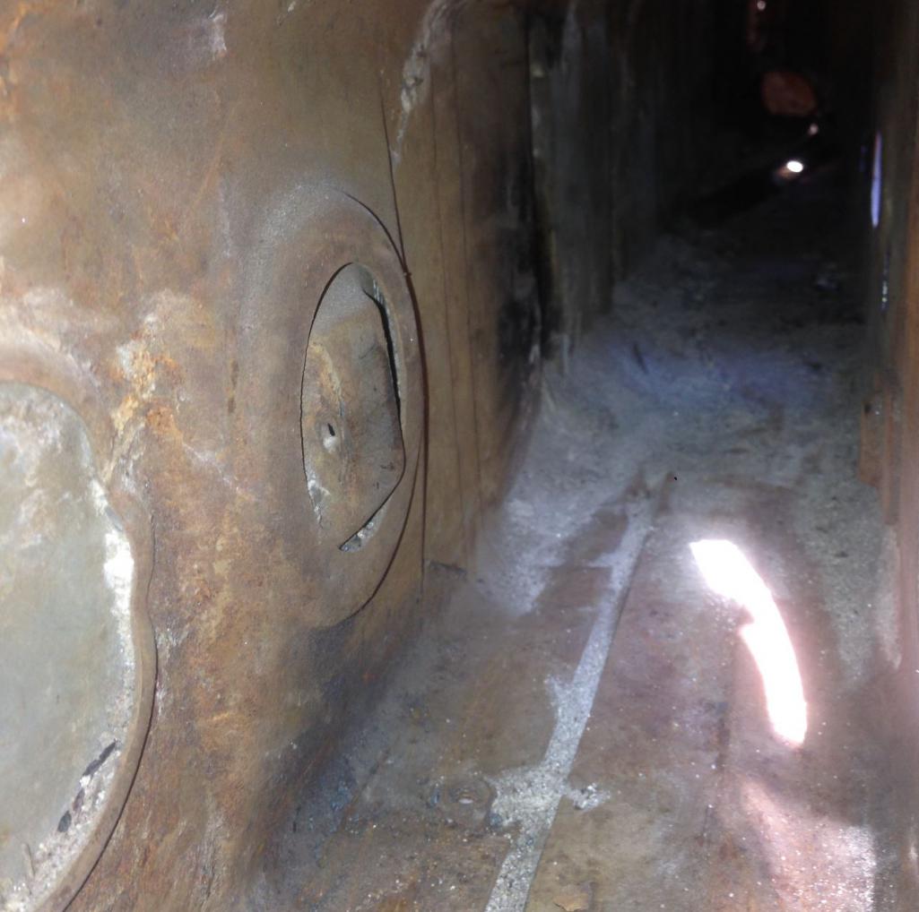
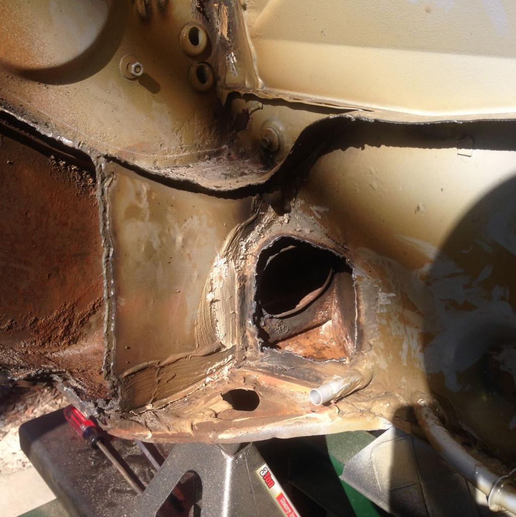
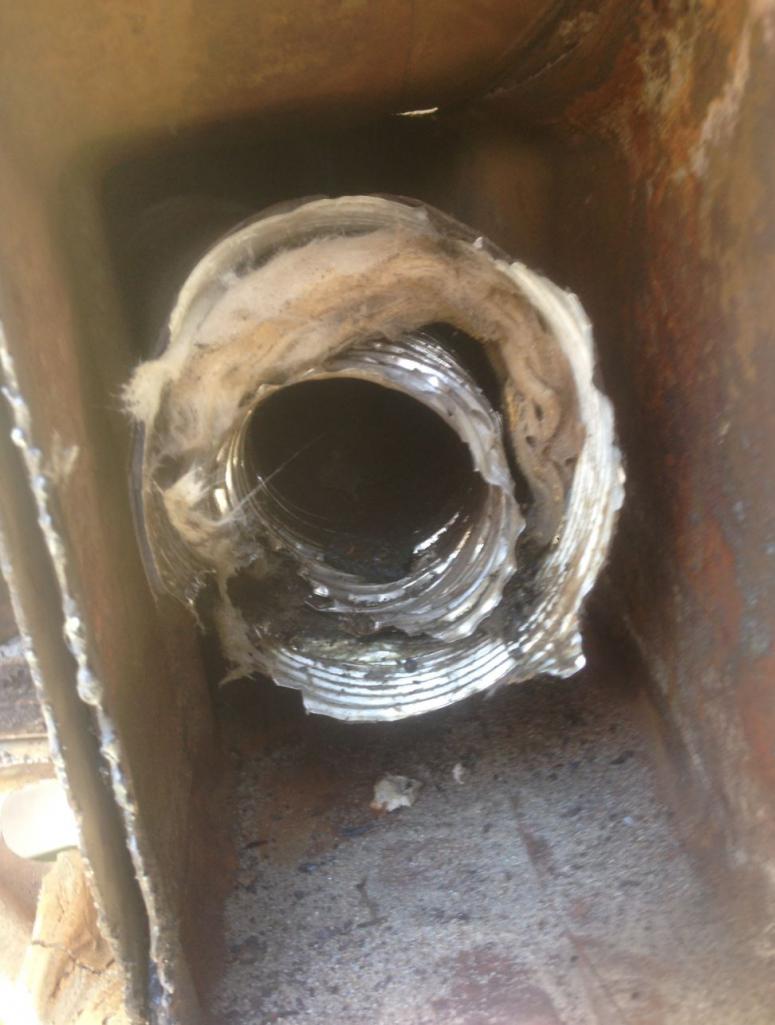
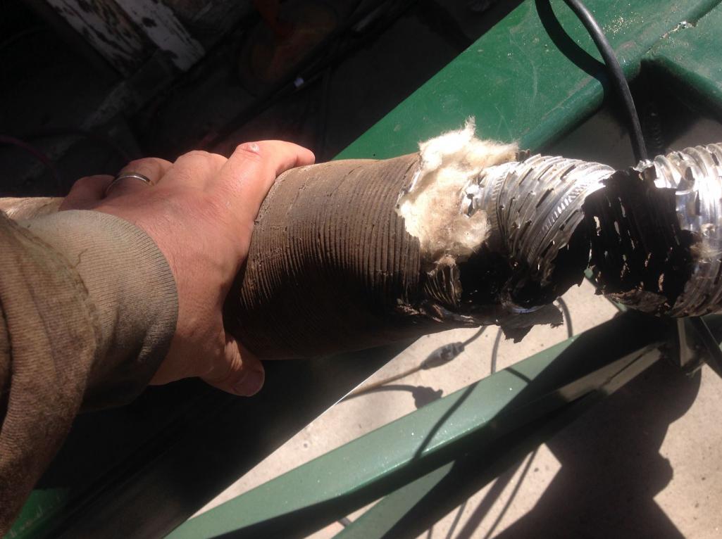
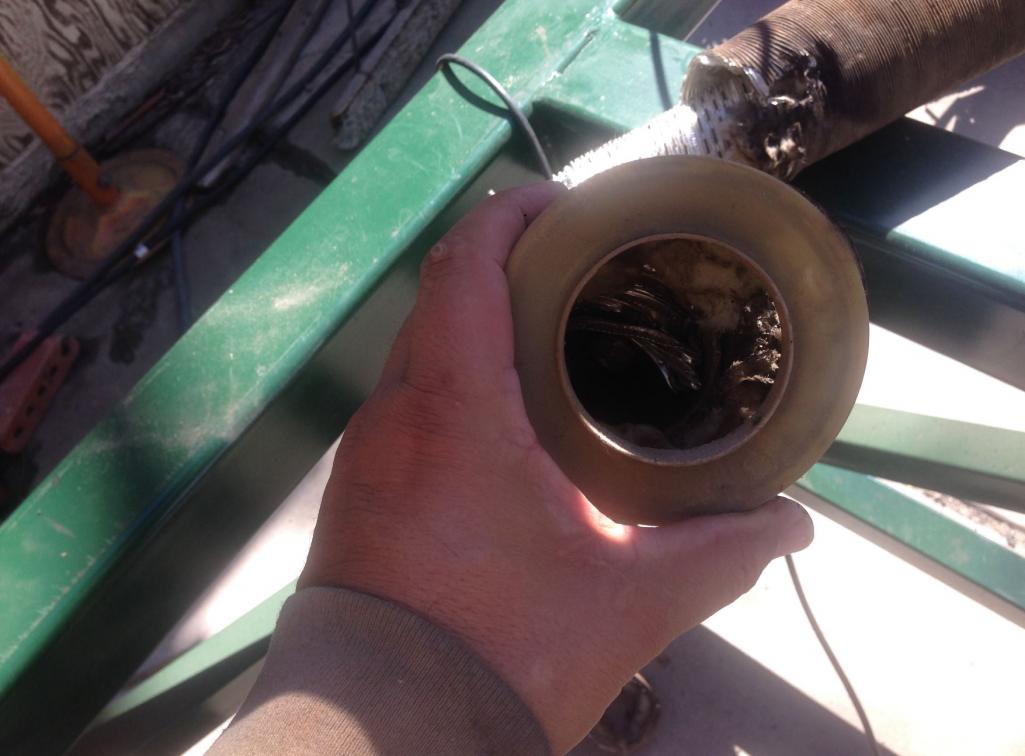
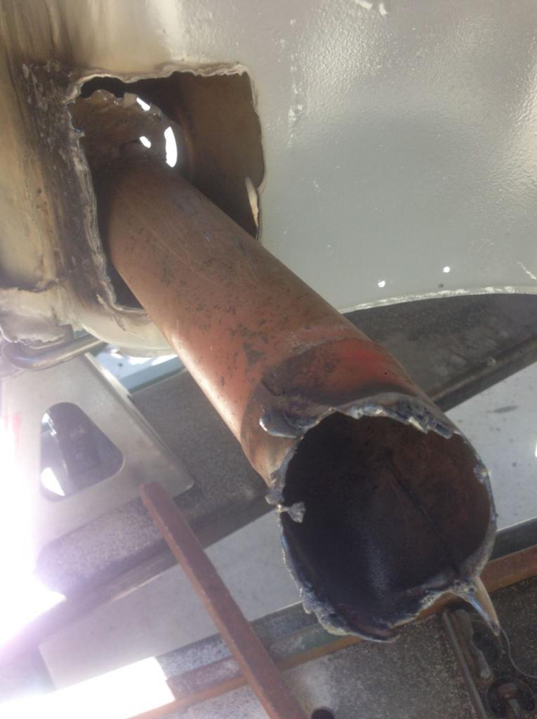
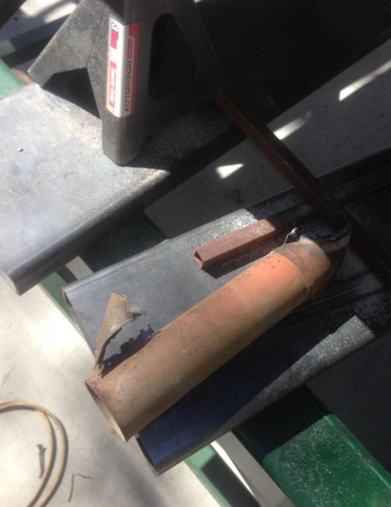
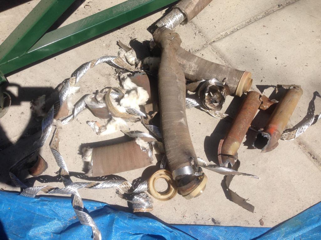
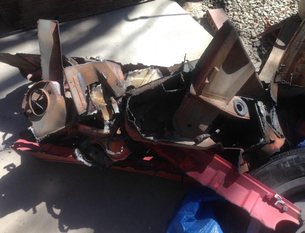
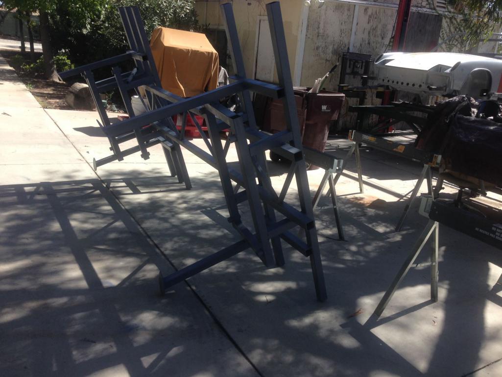
Posted by: Curbandgutter Sep 17 2016, 12:33 PM
This is what I'm thinking of for trussing the longs.
Attached thumbnail(s)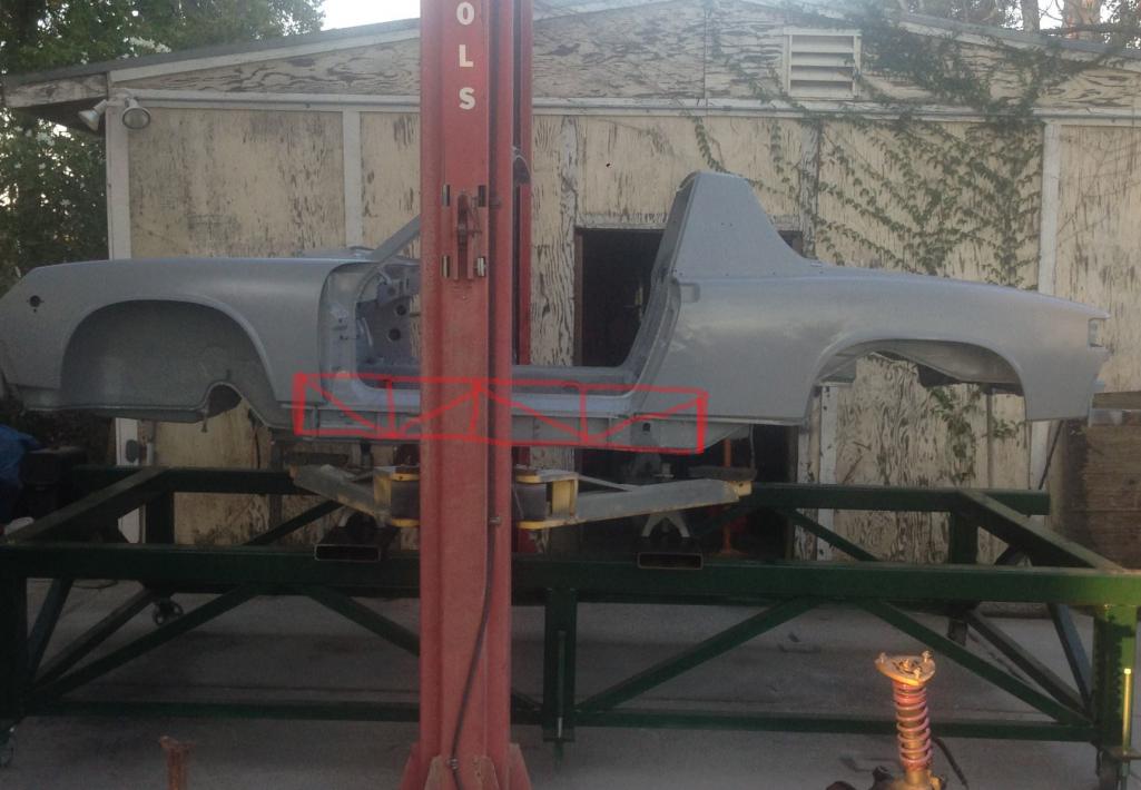
Posted by: Curbandgutter Sep 17 2016, 04:30 PM
996 SUSPENSION NEST MEETS 914......WELL HELLO THERE
Attached thumbnail(s)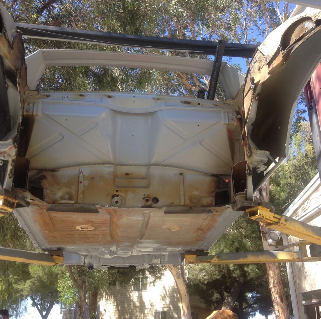
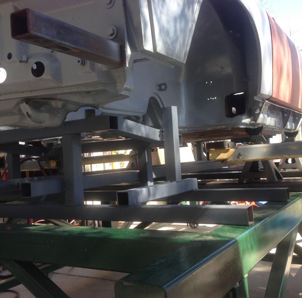
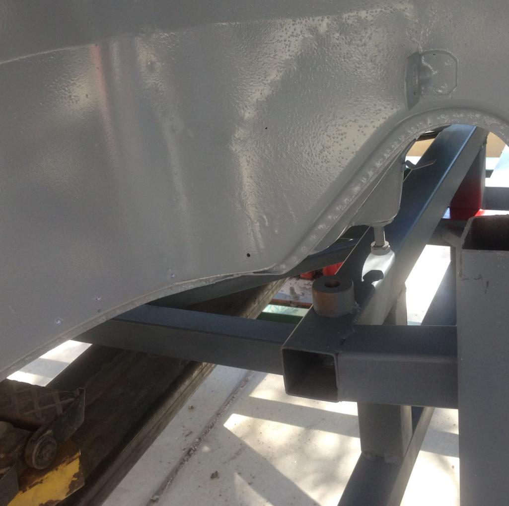
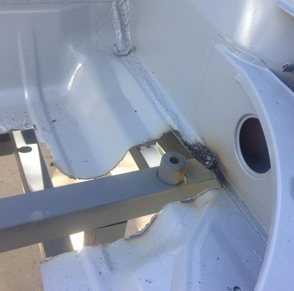
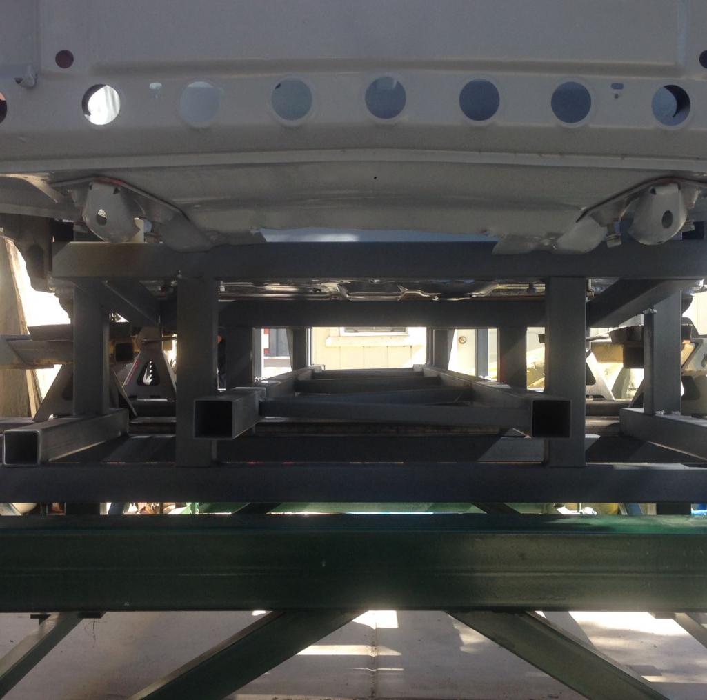
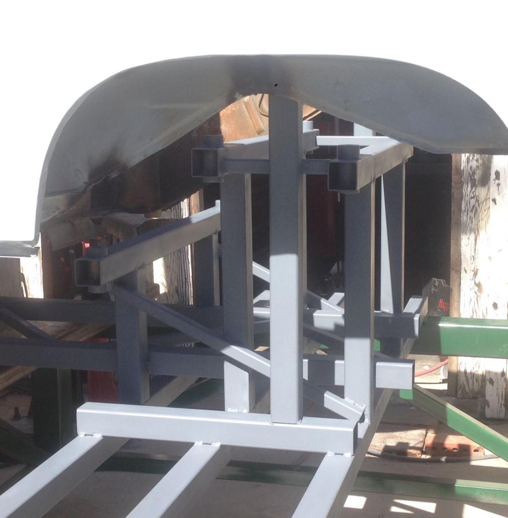
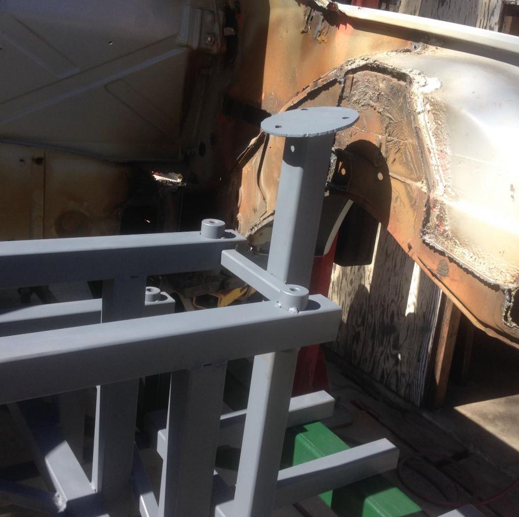
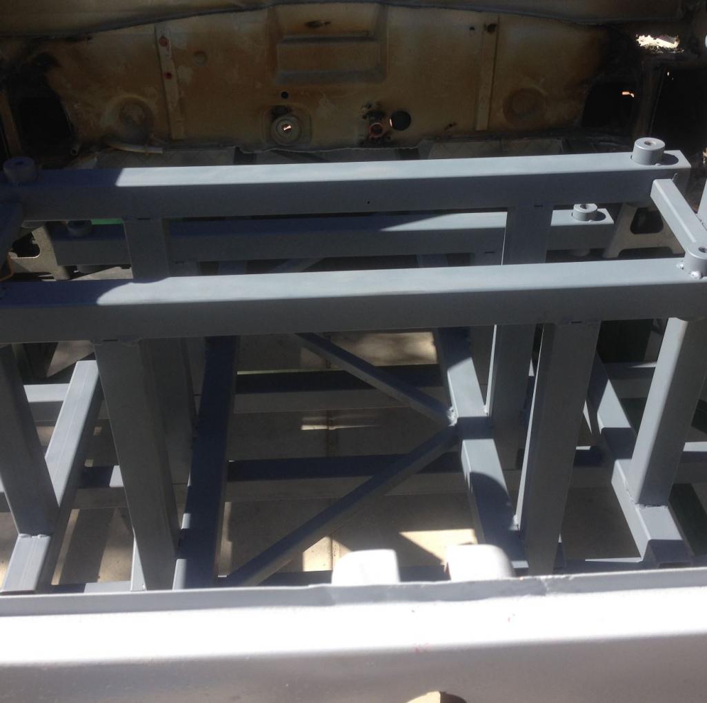
Posted by: Curbandgutter Sep 27 2016, 09:27 AM
Little update. I've been cleaning up the firewall before I install the tubes. I'm hoping to start bending and notching this weekend.
Attached thumbnail(s)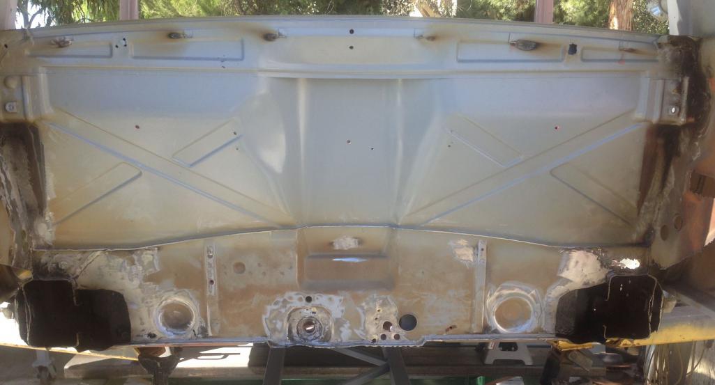
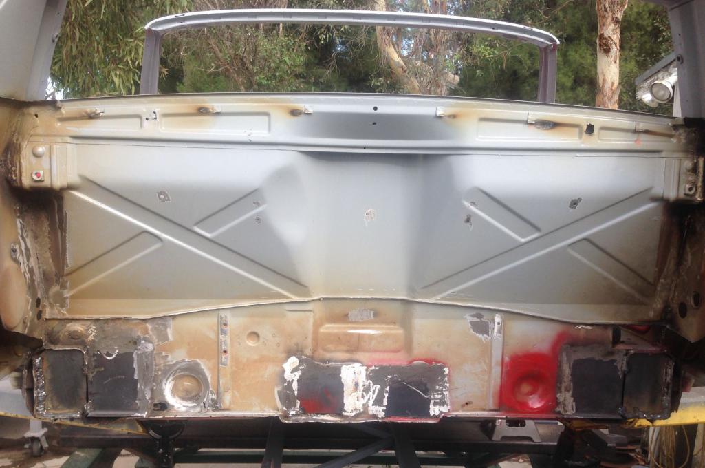
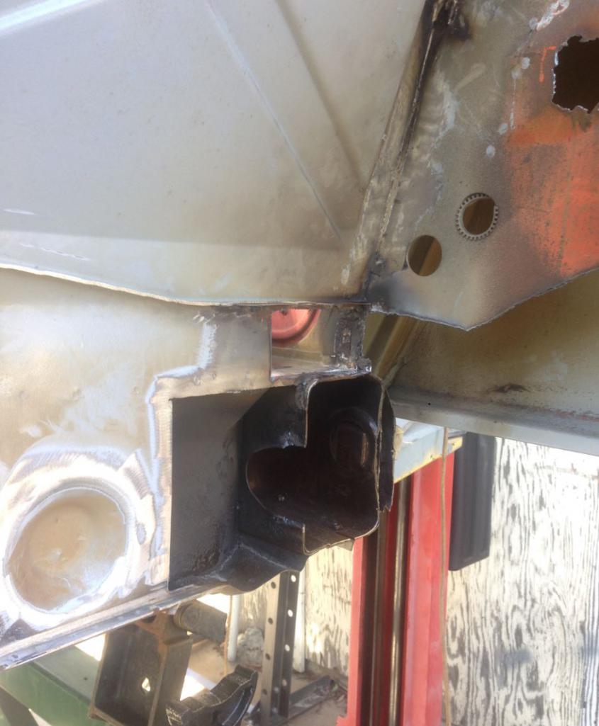
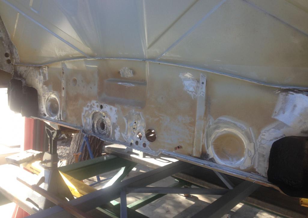
Posted by: Curbandgutter Oct 2 2016, 10:45 AM
Well I was able to insert some of the reinforcement for the longs.
DISCLAIMER: Do not attempt to duplicate anything that is mentioned or illustrated in the entirety of this thread. I do not make any warranties of any kind. If you try to build what I am doing, you take full risk. Do not try this. It may be dangerous to your health and may get you killed
Attached thumbnail(s)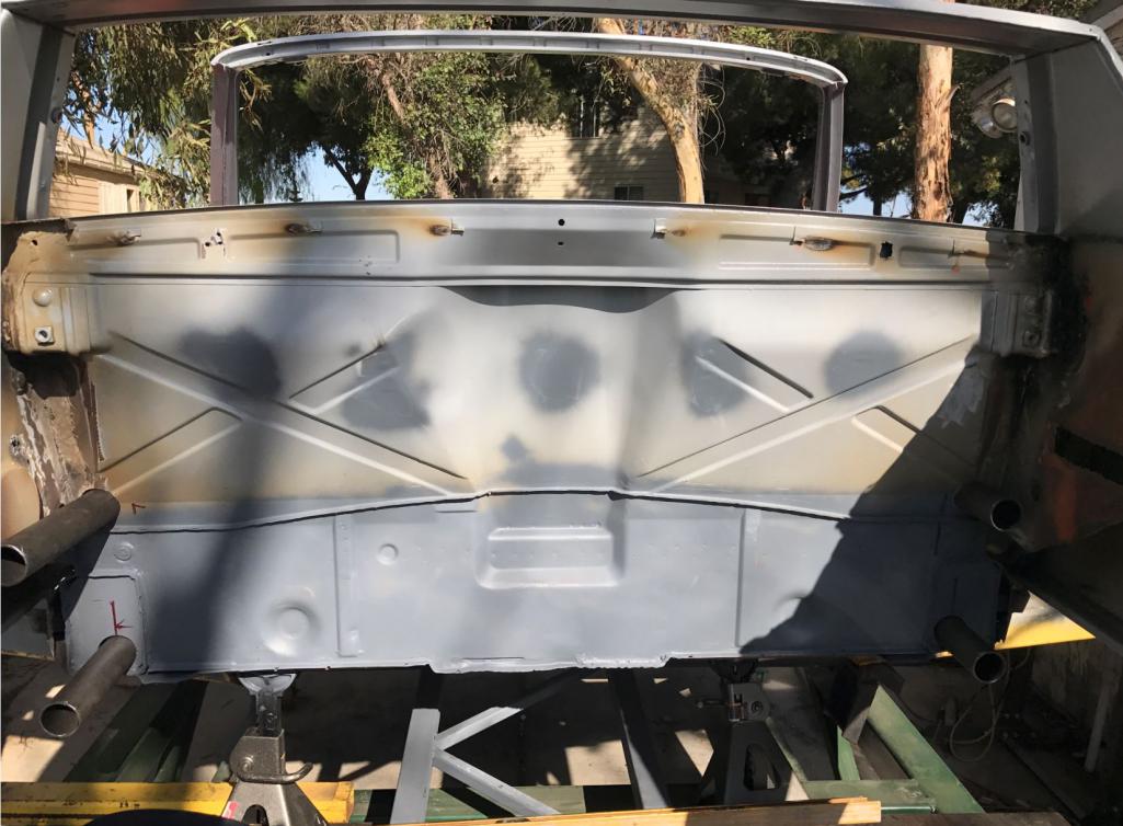
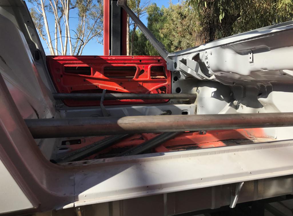
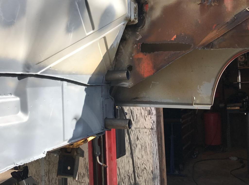
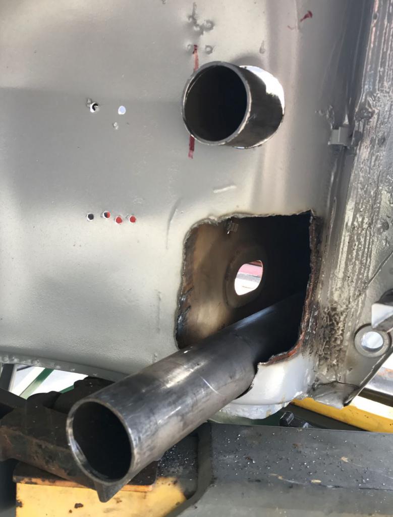

Posted by: Cracker Oct 2 2016, 11:01 AM
I'd call those loose ends.... 
Tony
Posted by: Curbandgutter Oct 17 2016, 11:07 AM
Well I've been bending and nothching the chassis. I made jig to be able to notch greater than 45 degrees. I have some tubes that need 70 degree bends. I hope to be able to complete the a and b pillar hoops this week. Then it's time to tie the a and b hoops to the front and rear suspension. I was really pleased with the nothching at steep angles. Came out really tight.
Attached thumbnail(s)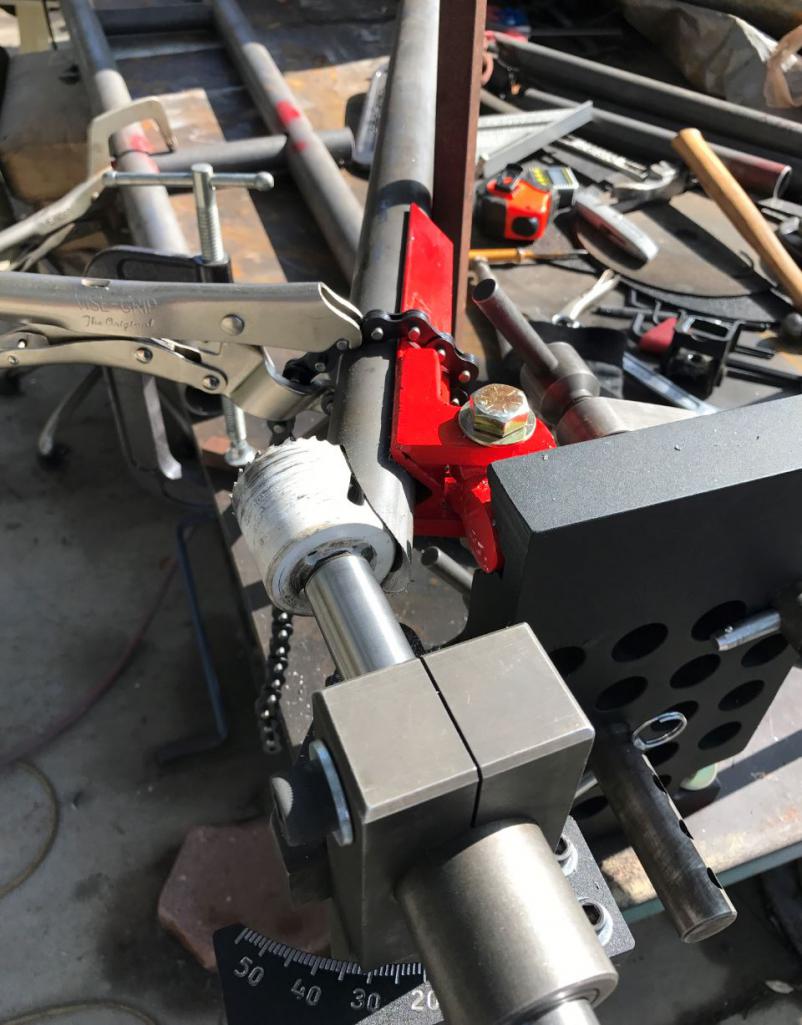
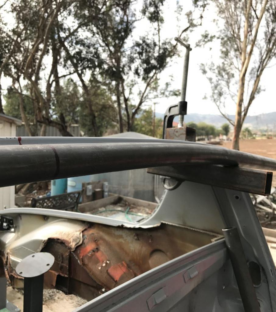
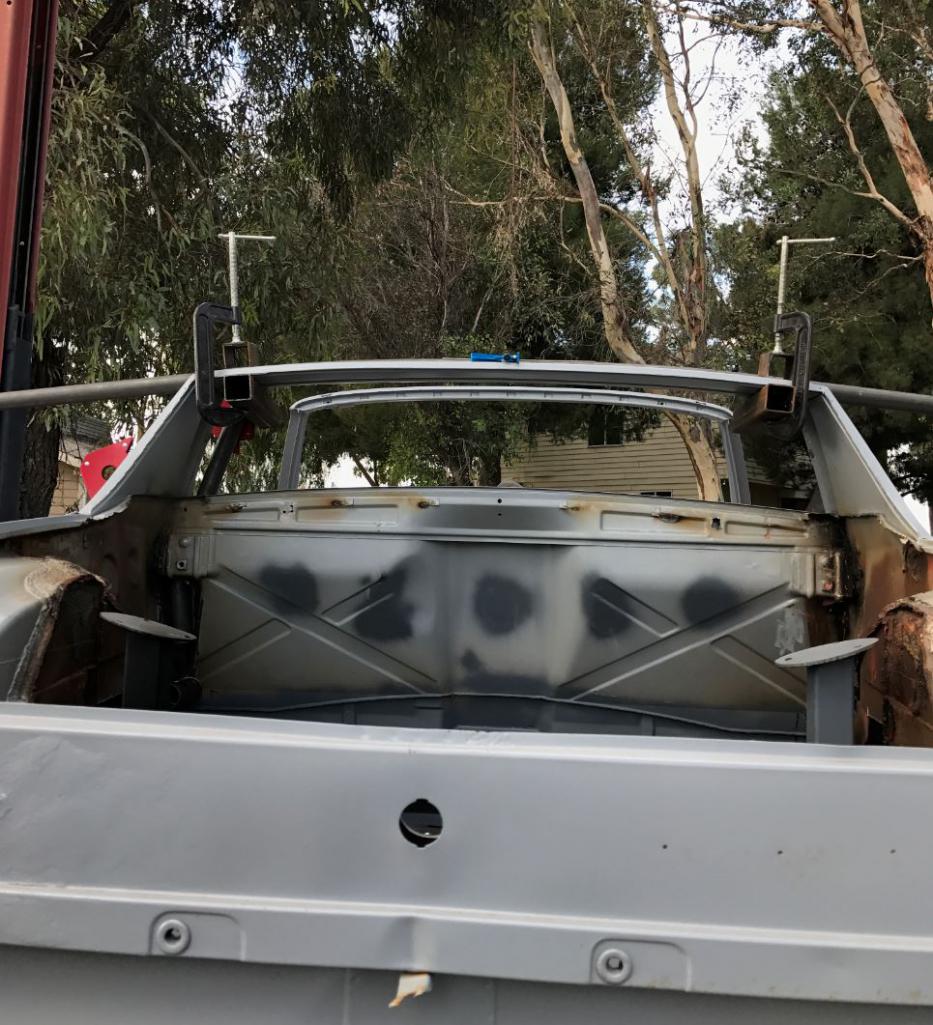
Attached image(s)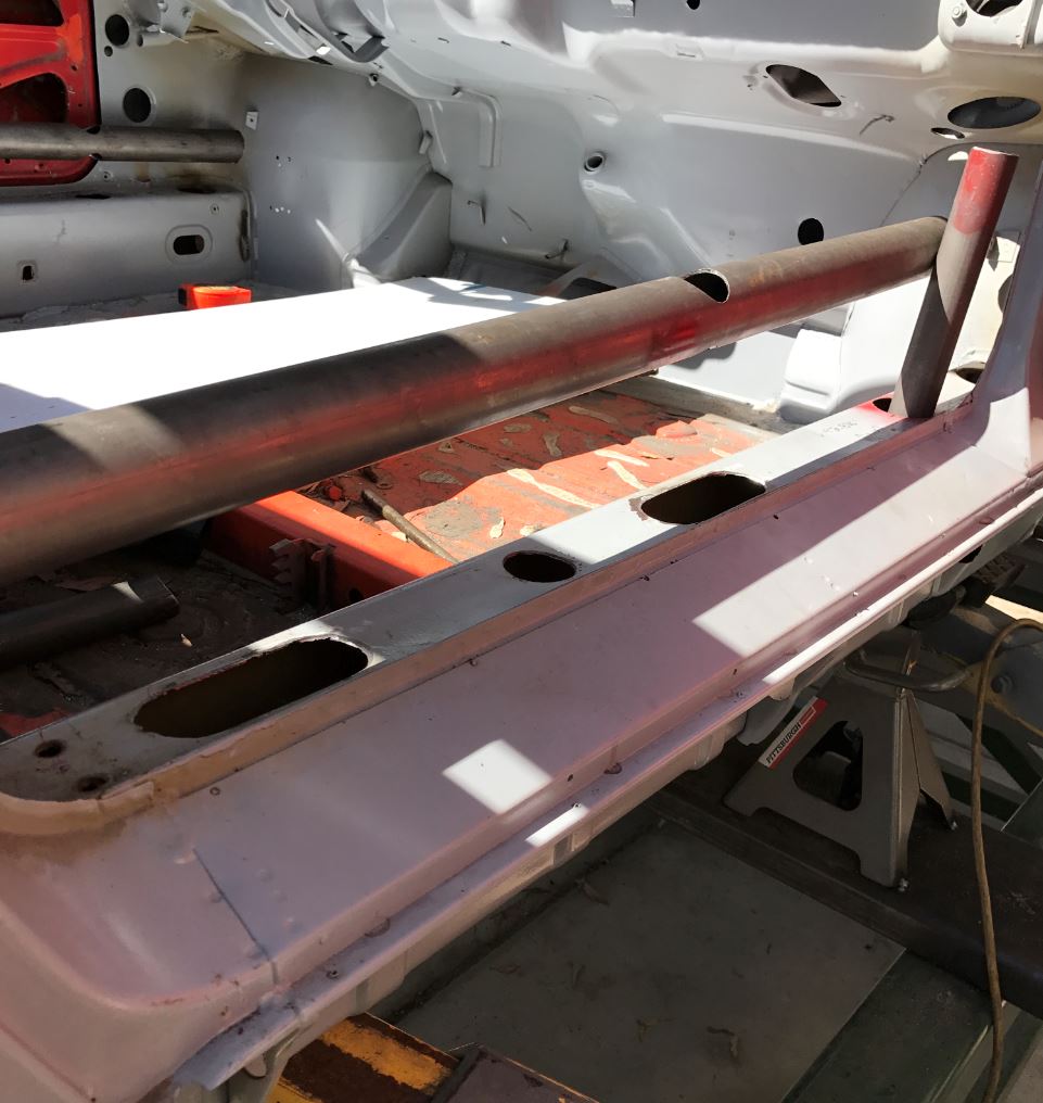
Posted by: csdilligaf Oct 17 2016, 02:04 PM
I see Progress. I all most stopped by to check in on the way back from the Pomona Car Swap. The oblong holes are for the truss pieces?
Posted by: siverson Oct 17 2016, 02:20 PM
Looks great. I'd love to see this in person some day too...
-Steve
Posted by: Cracker Oct 18 2016, 06:13 AM
Looks really nice...and to think I thought this might of been a pipe dream originally - you were actually dreaming of pipe! Keep us posted...
Tony
Posted by: Curbandgutter Oct 18 2016, 04:03 PM
I see Progress. I all most stopped by to check in on the way back from the Pomona Car Swap. The oblong holes are for the truss pieces?
Looks great. I'd love to see this in person some day too...
-Steve
Unless of course it's on jackstnads.Looks really nice...and to think I thought this might of been a pipe dream originally - you were actually dreaming of pipe! Keep us posted...
Tony
Posted by: Curbandgutter Oct 20 2016, 04:28 PM
Well I entered the 2017 Build off Challenge. Let's see how it goes.
Posted by: Curbandgutter Oct 24 2016, 09:43 AM
Well I finally finished bending the A and B pillars. The A pillar was tough! I had to measure, try, measure, try, measure, try......then screw up and try again.
Attached thumbnail(s)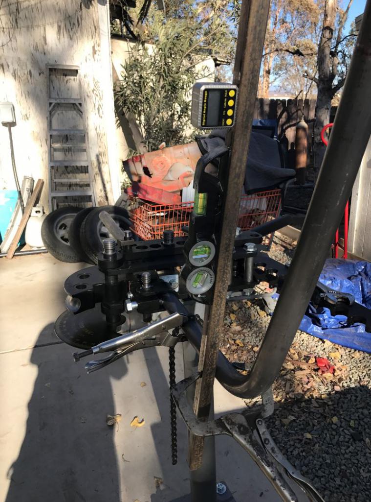
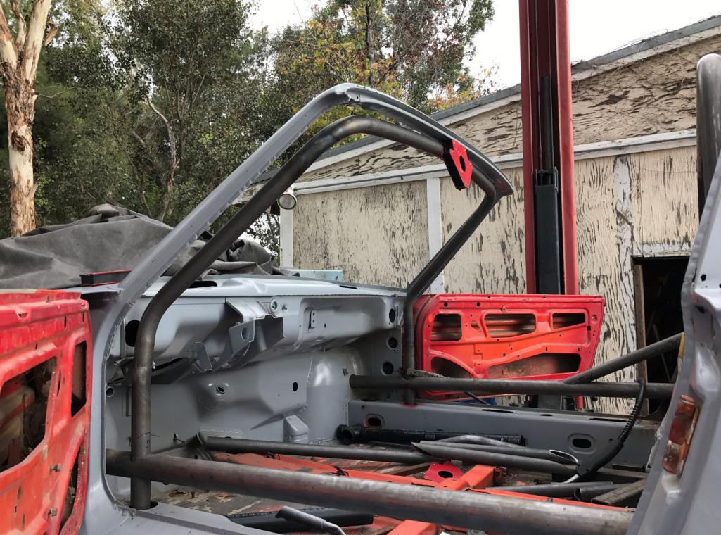
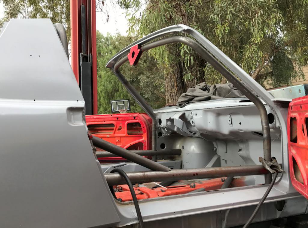
Posted by: tygaboy Oct 24 2016, 10:01 AM
The cage is looking great! I know what you mean about "measure, bend, try again."
I'm sure you're on top of this but the critical factor for me seems to be ensuring the tube doesn't creep as the bend starts. Well, that and being sure I'm bending the correct end of the tube! (Ask me how I know...)
Keep up the great work and lots of pics.
I need a regular fix!
Posted by: jd74914 Oct 24 2016, 10:24 AM
That cage is looking awesome Rudy! Are you using a JD2 bender?
Since you're MIG welding it might not help too much, but it has helped me while TIG welding so I thought I'd share...Apologies in advance if you've heard this before, etc.
If you drill a small hole at each tube junction so the whole cage is one single volume, you can back purge and the quality of the welds is much nicer. Even without purging, the holes let any of the smoke from oil in the tubes move so you don't get any blowouts from pressure buildup while heating and the welds tend to be cleaner.
Posted by: Andyrew Oct 24 2016, 12:30 PM
I just did a roll hoop for a Miata and used 1/2" conduit to form the outer edge of the hoop.. Might be cheaper to grab some conduit than messing up that nice DOM?
Posted by: 914forme Oct 24 2016, 12:36 PM
Andrew, so you used the conduit to make a test piece? I'm a bit confused by your statement.
Posted by: Andyrew Oct 24 2016, 01:37 PM
Andrew, so you used the conduit to make a test piece? I'm a bit confused by your statement.
Yes, sorry. Conduit for test piece, then .120 wall DOM tubing for the actual hoop. I can see your confusion
Posted by: 914forme Oct 24 2016, 04:13 PM
Makes perfect sense now.
Posted by: Curbandgutter Oct 24 2016, 04:50 PM
The cage is looking great! I know what you mean about "measure, bend, try again."
I'm sure you're on top of this but the critical factor for me seems to be ensuring the tube doesn't creep as the bend starts. Well, that and being sure I'm bending the correct end of the tube! (Ask me how I know...)
Keep up the great work
and lots of pics.I need a regular fix!
Thanks for the compliment. I'm using the JD2 model 32 bender and tube creep was never an issue. Do you have something other than a JD2 bender.
That cage is looking awesome Rudy!
Are you using a JD2 bender?Since you're MIG welding it might not help too much, but it has helped me while TIG welding so I thought I'd share...Apologies in advance if you've heard this before, etc.
If you drill a small hole at each tube junction so the whole cage is one single volume, you can back purge and the quality of the welds is much nicer. Even without purging, the holes let any of the smoke from oil in the tubes move so you don't get any blowouts from pressure buildup while heating and the welds tend to be cleaner.
Hey Jim....yes JD2 model 32. That's good advice on the back purging. I will save that for when I do the headers. Yes you're right I'm MIG welding the frame so no back purging required.
Posted by: Curbandgutter Oct 24 2016, 04:56 PM
I just did a roll hoop for a Miata and used 1/2" conduit to form the outer edge of the hoop.. Might be cheaper to grab some conduit than messing up that nice DOM?
Yes that is a good suggestion. I ruined 2 hoops (the rear "easy one")l, but I just need to cut the bends off and then I have material for the webs. But yes after I ruined two hoops I learned the error of my ways and was able to do the A pillar hoop in one try. If you notice the A pillar hoop is complex in that it has an offset bend and it also has a slight arch that follows the roof line. That arch is not in the plane of the windshield it is twisted about 47 degrees from the plane of the windshield. It was tricky but I did it and am satisfied with the result.
Posted by: 914forme Oct 24 2016, 06:49 PM
I was always taught to drill tubes when welding, otherwise you run the risk of making it a pressurized vessel and it may blow out. Molten Metal is not a fun shower.
Do you guys back purge more than just Stainless
Posted by: jd74914 Oct 24 2016, 08:07 PM
I was always taught to drill tubes when welding, otherwise you run the risk of making it a pressurized vessel and it may blow out. Molten Metal is not a fun shower.
Do you guys back purge more than just Stainless
Here are my rules for back purging from the old school welders I used to work with (these were aircraft welders who only wire brushed in one direction, degrease before and after brushing, etc.):
- 100% of the time if TIG welding carbon steel, stainless, or titanium tubing (just as you would if welding piping or pressure vessels).
- No back purging for aluminum tubing
- Typically no back purging for MIG welding, though it does help on thin tubing. If someone else is paying for the gas absolutely back purge.
Sorry for the hijack Rudy.
Posted by: Curbandgutter Oct 25 2016, 03:42 PM
No highjacking just good information for those that are following the thread. And yes, I agree no need to backpurge for mig on mild steel. Also, I have never heard of the situation where the tube becomes a pressure vessel? Wow that is amazing and I am having a hard time believing it. One would think that the conditions for it would have to be a one in a million. It's possible but not probable, practically speaking.
Posted by: jd74914 Oct 25 2016, 09:29 PM
While certainly not pressure vessel grade, I've had melt blowout problems with smaller sealed tubes while TIGing. We're talking about 1" tubing of about a foot or little longer length. While not dangerous it's certainly inconvenient.
Posted by: Curbandgutter Oct 26 2016, 07:39 PM
Well completed trussing the long on the right side. Material is all cut for the left side....that is next. I love the look that it's getting. I also removed the center tunnel. That is going to get some extra special treatment . It will add tremendous stiffness to the chassis.
Attached thumbnail(s)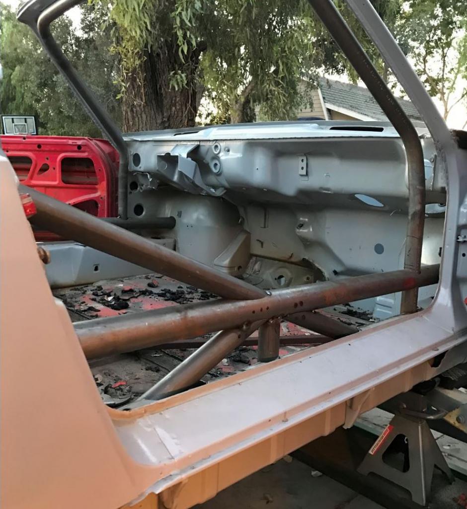
Attached image(s)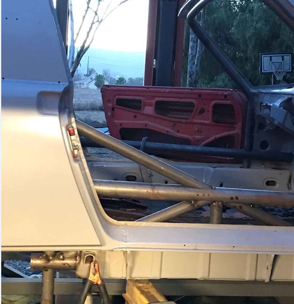
Posted by: csdilligaf Oct 27 2016, 07:16 AM
Nice and tight tube notching and fitment you did there Rudy. That should really stiffen things up.
Posted by: Curbandgutter Oct 30 2016, 09:24 PM
Ok finished other side. Next step is to tie front and rears to new strut towers. Ohhhh...I'm lengthening wheelbase by 2 inches
Attached thumbnail(s)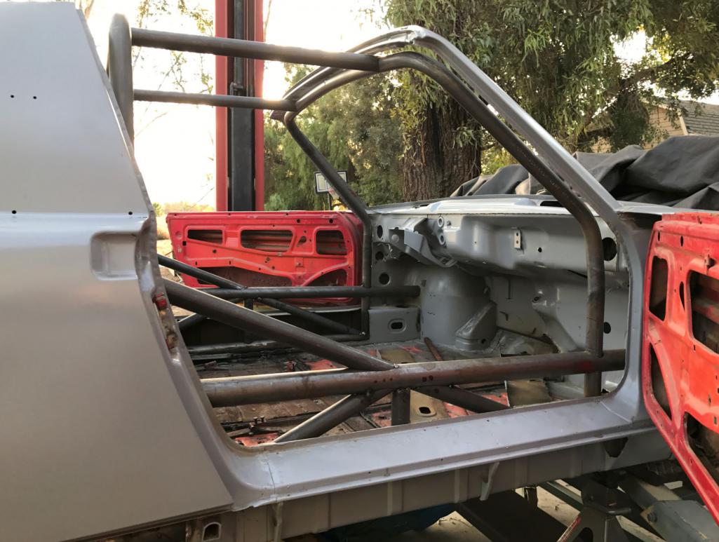
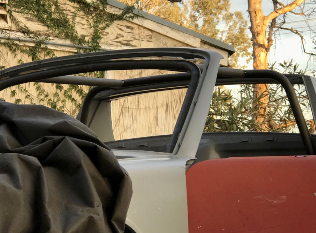
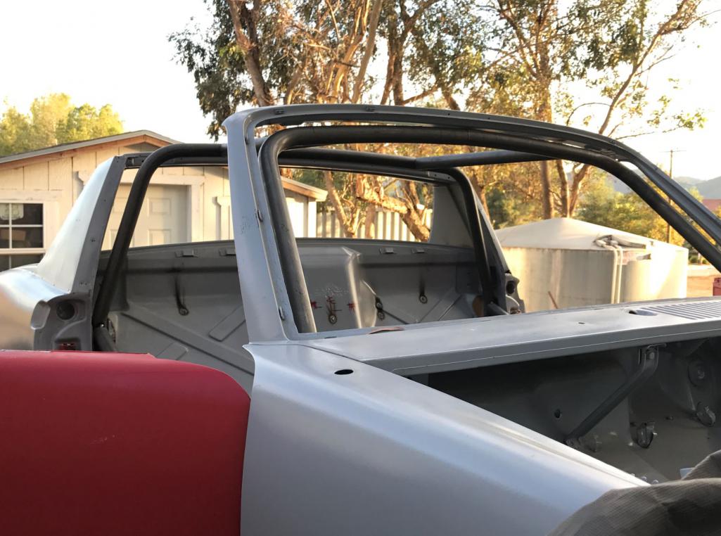
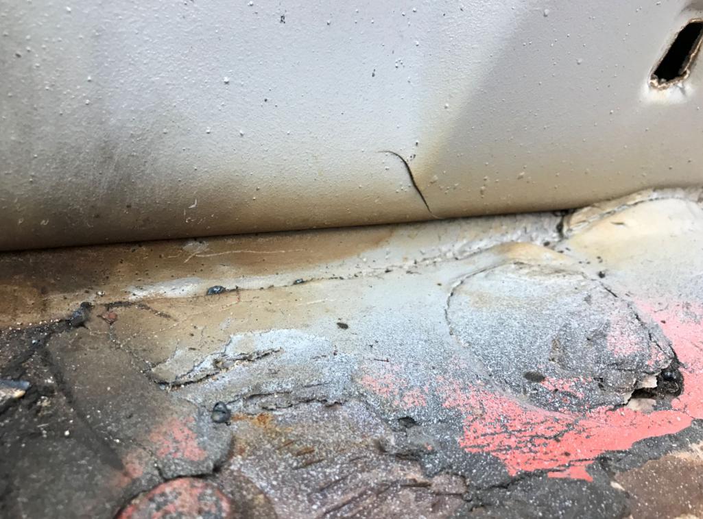
Posted by: Curbandgutter Oct 30 2016, 09:27 PM
While adding long reinforcement I noticed this stress crack in the long.
Attached thumbnail(s)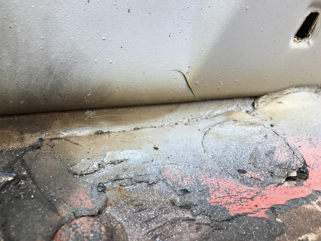
Posted by: MichiganMat Oct 31 2016, 04:46 AM
Whats your thinking behind the placement of those upper bars connecting the front and rear hoops?
Im concerned that they are placed too far inward which could put them directly over the drivers head instead of off to the side. Is there a reason you haven't placed them off to the corners? Theres not a lot of headroom for drivers & passengers as it is in these cars, you might consider putting them as far off to the corners as possible.
Loving the build so far, keep the pictures coming!
Posted by: Andyrew Oct 31 2016, 07:11 AM
Ok finished other side. Next step is to tie front and rears to new strut towers. Ohhhh...I'm lengthening wheelbase by 2 inches
2 inch wheelbase lengthening? That would be awesome.. That would really increase the stability at your power level.
Posted by: Curbandgutter Oct 31 2016, 03:01 PM
Whats your thinking behind the placement of those upper bars connecting the front and rear hoops?
Good eye Michigan! Actually they are place holders for right now. I will only add them if the twist test shows an appreciable improvement in torsional stiffness.
Ohhhh...I'm lengthening wheelbase by 2 inches
2 inch wheelbase lengthening? That would be awesome.. That would really increase the stability at your power level.
Yes, the lengthening came about from thinking how this would give me a better straight line stability. Two inches is a number that I can sneak in and still look like a regular teener. This gives me more room in the engine compartment and allows the cv axles to line up better with the transaxle.
Posted by: Cracker Oct 31 2016, 07:27 PM
That would be wonderful...my drive flange to hub centerline is 2.6" - a 2" increase would be ideal. With a little massaging - I will be able to retrieve about 1". Jealous.
T
This gives me more room in the engine compartment and allows the cv axles to line up better with the transaxle.
Posted by: 76-914 Oct 31 2016, 07:33 PM
You gonna tell 'em about the other 2" mod or is that classified? Kent
Posted by: Curbandgutter Nov 1 2016, 11:03 AM
You gonna tell 'em about the other 2" mod or is that classified?
KentThat i s"HIGHLY" classified

Posted by: Curbandgutter Nov 1 2016, 12:52 PM
I forgot to add that I tied both of the truss longs with a rear firewall truss. This will stiffen things up a bit.....torsionally speaking
Attached thumbnail(s)
Posted by: 76-914 Nov 1 2016, 05:28 PM
You gonna tell 'em about the other 2" mod or is that classified?
KentThat i s"HIGHLY" classified
Thought so; Mum's the word.
Posted by: Mike Bellis Nov 1 2016, 05:42 PM
I think you are going to bang your head on the overhead bars on the first bump.
Posted by: 914forme Nov 1 2016, 06:08 PM
Mike, he said they where there as spacers right now.
Move them inboard and you can build the B B tribute 914. After all their 928 was a targa also.
Posted by: Curbandgutter Nov 1 2016, 09:43 PM
I think you are going to bang your head on the overhead bars on the first bump.
That's one hell of a bump. I'm 5-4"
Posted by: Curbandgutter Nov 1 2016, 09:49 PM
Mike, he said they where there as spacers right now.
Move them inboard and you can build the B B tribute 914. After all their 928 was a targa also.
Hahaha. I remember those seats. I think Recaro made those?? In seriousness, I'm not too sure I'm going to use the tie bars for the a and b pillars. If they give me a 5% increase in stiffness then I'll use them. Otherwise they're out.
Posted by: jmmotorsports Nov 3 2016, 06:42 AM
when is the work going to start???
jerry
Posted by: Curbandgutter Nov 3 2016, 03:36 PM
when is the work going to start???
jerry
What do you mean? I don't understand your question?
Posted by: sb914 Nov 3 2016, 05:33 PM
when is the work going to start???
jerry
What do you mean? I don't understand your question?
I think he's joking.you got soooo much done little time.
Posted by: sb914 Nov 3 2016, 05:34 PM
when is the work going to start???
jerry
What do you mean? I don't understand your question?
I think he's joking.you got soooo much done in little time.
Posted by: AZBanks Nov 3 2016, 08:31 PM
when is the work going to start???
jerry
What do you mean? I don't understand your question?
I think that was sarcasm but it went right over your head.
(Yeah, I made a short guy joke)

Posted by: Curbandgutter Nov 7 2016, 12:36 PM
when is the work going to start???
jerry
What do you mean? I don't understand your question?
I think that was sarcasm but it went right over your head.
(Yeah, I made a short guy joke)
You're too funny, seems like the sarcasm went over both of our heads.
I'm actually 6'. It is almost impossible to "read into" sarcasm as you can see . Anyway, I was able to get the suspension jig lined up under the 914. I stretched the wheelbase 3". I also raised the suspension jig 3/4" into the 914 thereby lowering the ride height by 3/4" as compared to a stock 996. The cool thing about this is that by lowering it this way, it will retain the stock 996 ride but in a lowered stance and the ride quality will be completely unaffected. Attached are the pictures of the suspension jig in place.
Attached thumbnail(s)
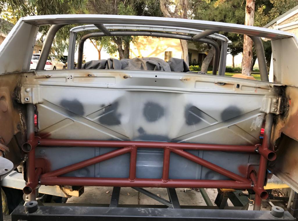
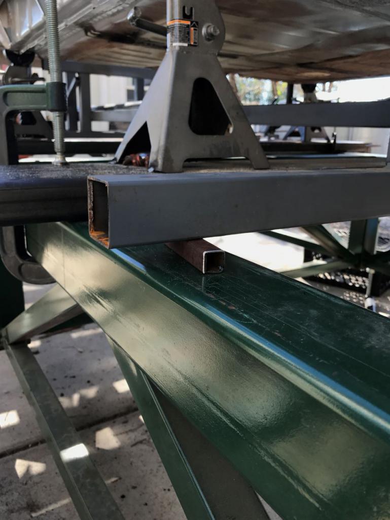
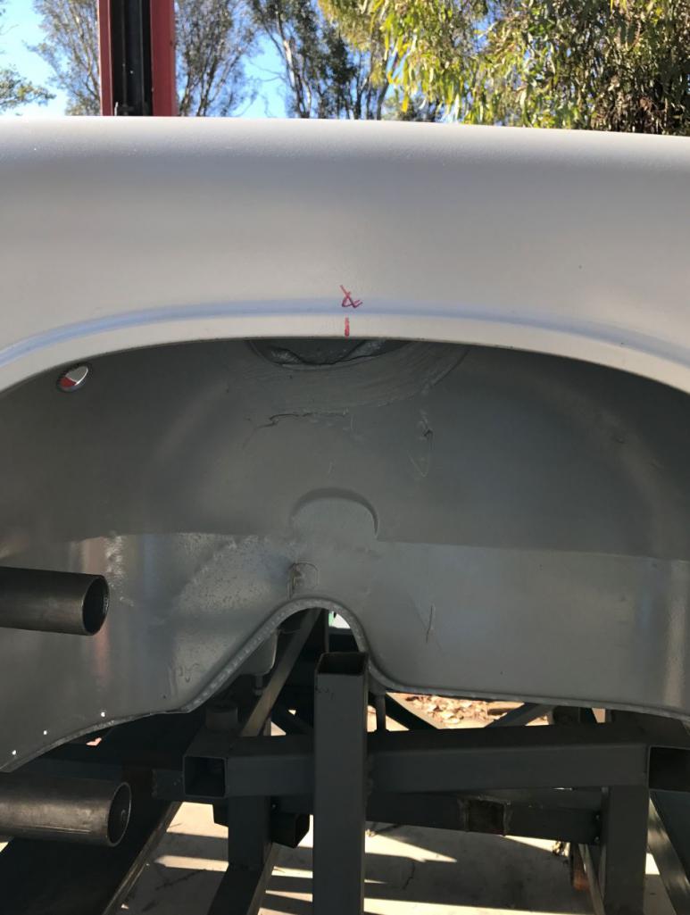
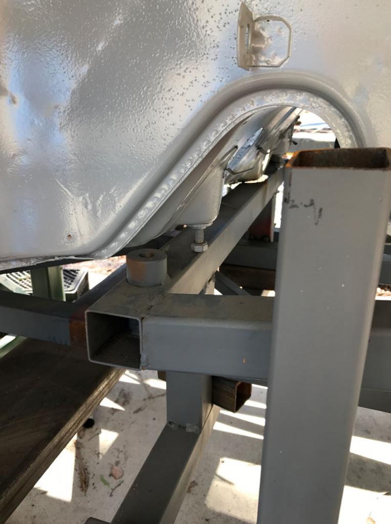
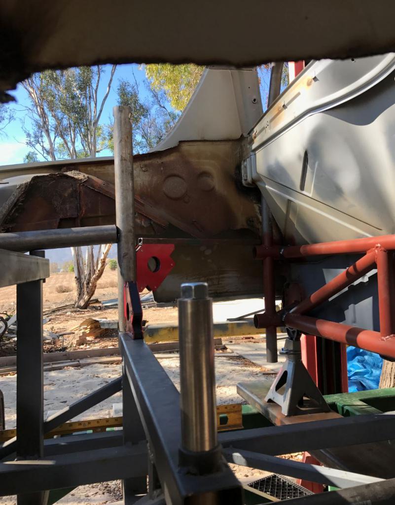
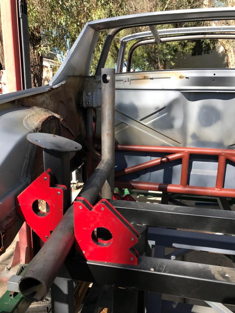
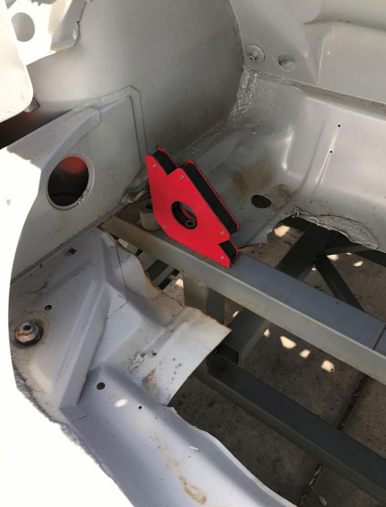
Posted by: Curbandgutter Nov 10 2016, 10:30 AM
Here are some shots of the rear suspension pick up points. I hope to have the rear completed this weekend and then move to the front.
Attached thumbnail(s)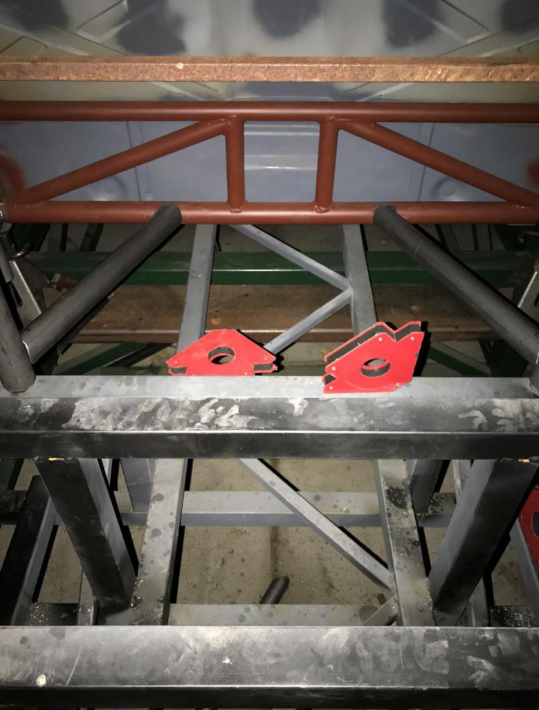
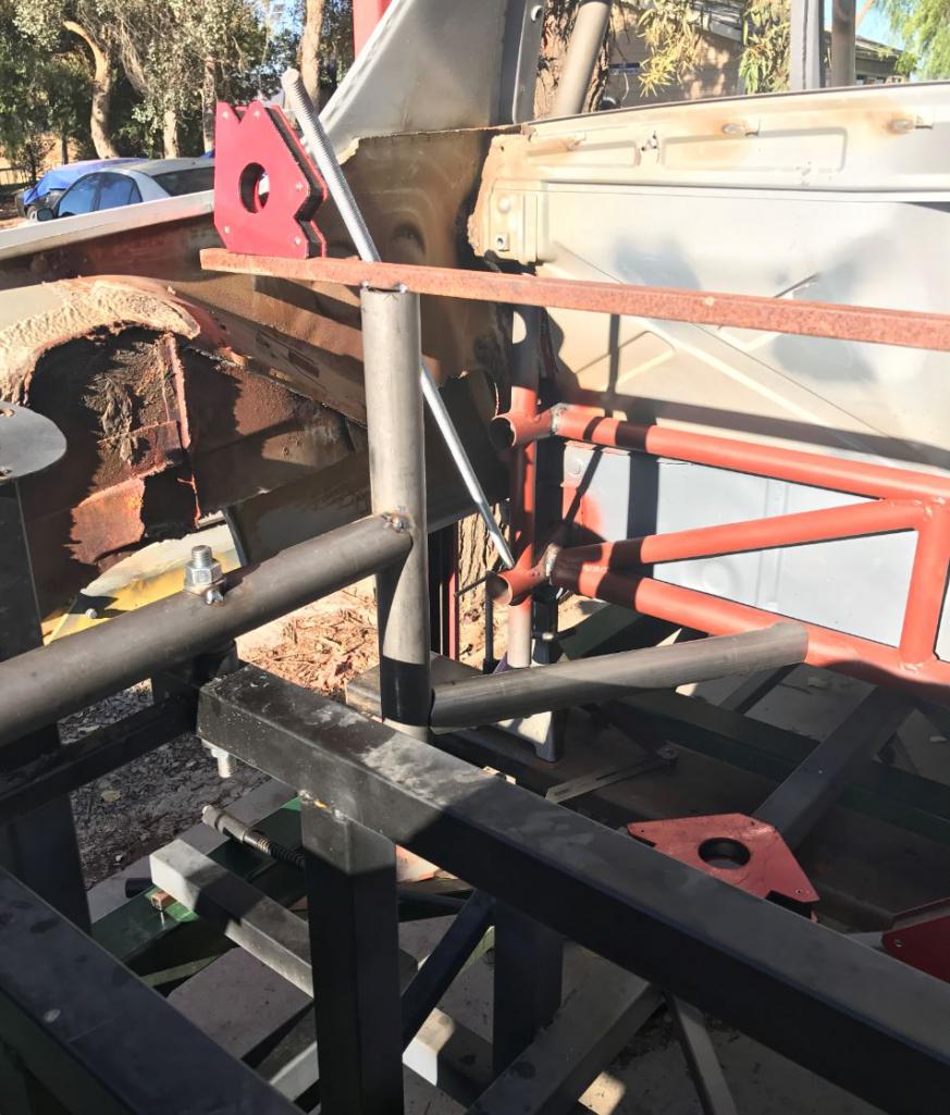
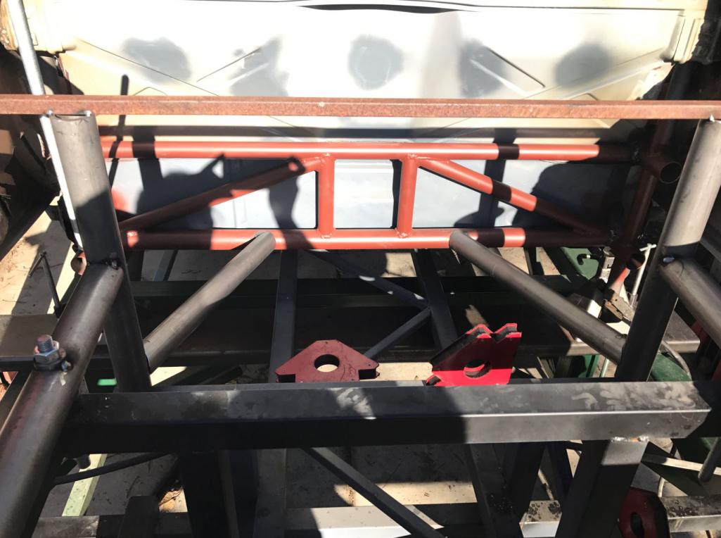
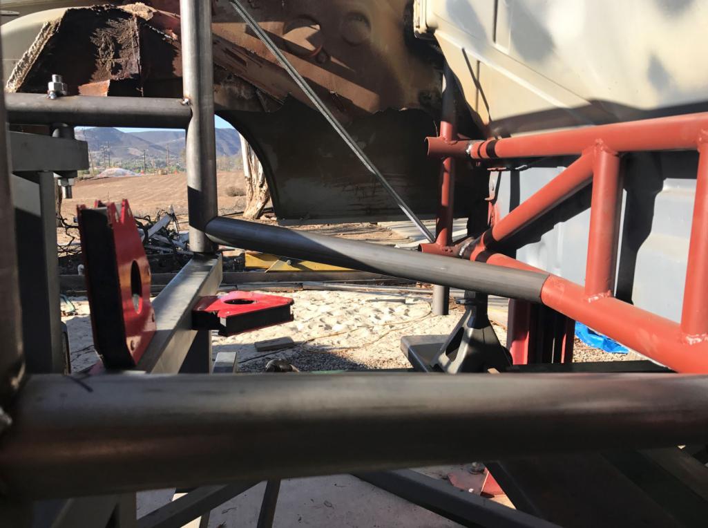
Posted by: Cracker Nov 10 2016, 10:58 AM
Posted by: csdilligaf Nov 10 2016, 06:29 PM
Hey! Have you been sneaking in some progress during the work week? Looks good
Posted by: tygaboy Nov 11 2016, 09:46 AM
Hey! Have you been sneaking in some progress during the work week? Looks good
Progress made during work days!?!? Unfair advantage!!
(until I retire, that is...)
Tony (Cracker) and I were talking about your build and he pointed out that there may be no other car on the planet that lends itself to such a wide range of modifications. Your build is another (great) example of this.
Awesome progress! I can't to see the wheelbase extend phase of this build.
Posted by: Curbandgutter Nov 11 2016, 10:46 AM
Hey! Have you been sneaking in some progress during the work week? Looks good
Progress made during work days!?!? Unfair advantage!!
(until I retire, that is...)
Tony (Cracker) and I were talking about your build and he pointed out that there may be no other car on the planet that lends itself to such a wide range of modifications. Your build is another (great) example of this.
Awesome progress! I can't to see the wheelbase extend phase of this build.
Ha ha ha, yes unfair advantage. I'm not retired however. Since I'm self employed, I sometimes take the time when I need a "mental pressure" holiday. Working on the 914 is a stress reliever for me. And yes aren't these 914s incredible platforms to modify? I've enjoyed seeing your's and Tony's post as well. By the way. the wheelbase is already extended, it's just that you won't be able to see it until the suspension is installed. I'm going to have to modify the rear 916 flares. I think it's going to have a look similar to the Audi R8 in the rear. It will still hold it's distinctive 914 look though. I want this to look like the "next level" 916. It will be about wider that than a typical 916 and the wheelbase will be 3" longer. I'm super excited with the way it's coming together. Thanks for the encouragement.
Curbandgutter (Rudy)
Posted by: Curbandgutter Nov 13 2016, 12:08 PM
Almost done tying the rear into the car!!!! Had to finish early off to my 7th wedding this summer/fall.
Attached thumbnail(s)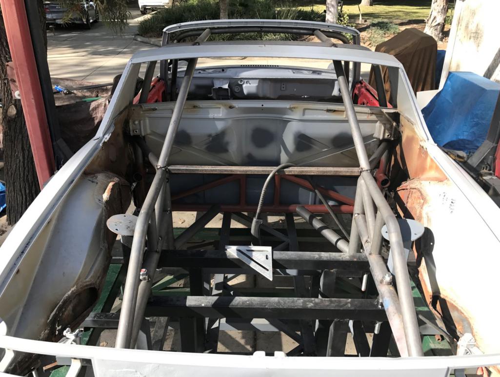
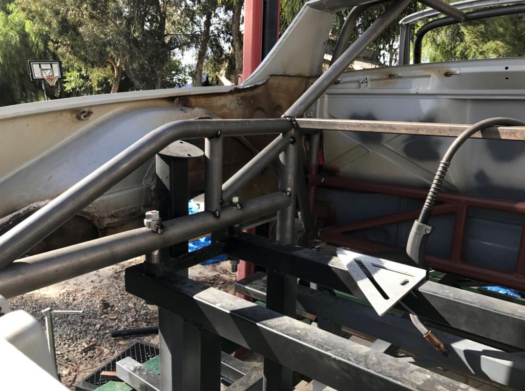
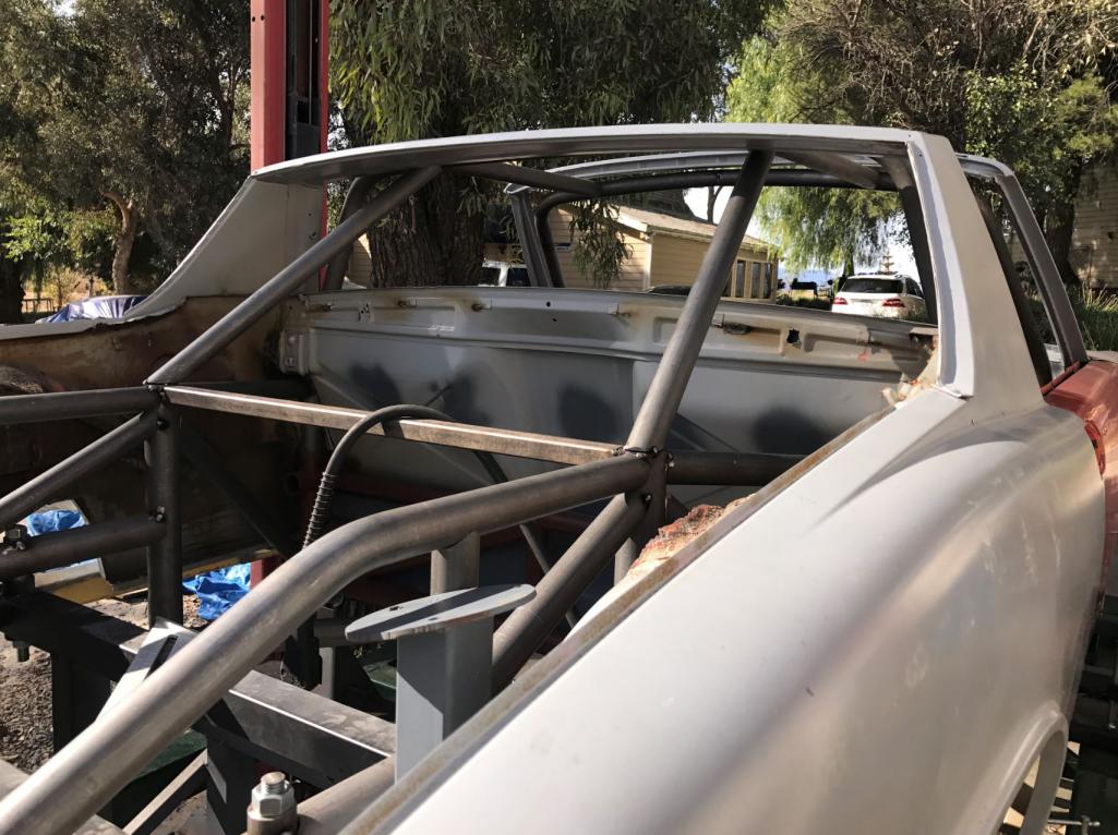
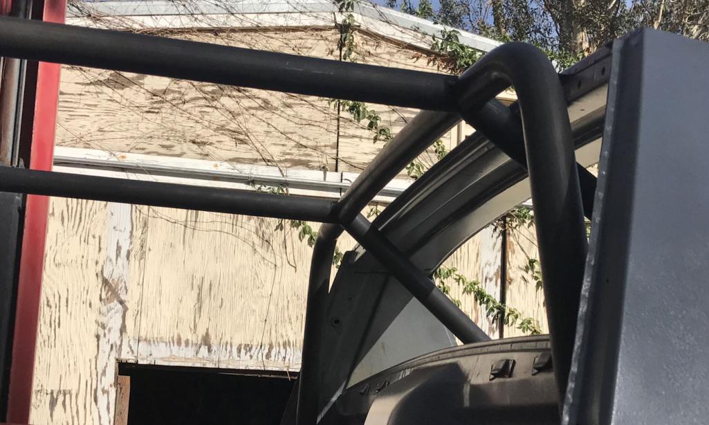
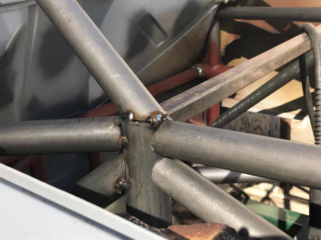
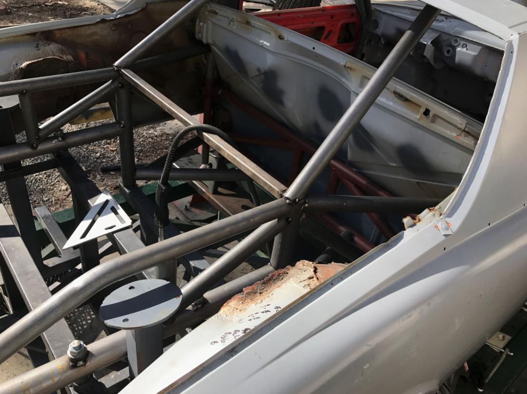
Posted by: tygaboy Nov 13 2016, 12:13 PM
Good Lord! 
Posted by: Cracker Nov 13 2016, 03:00 PM
Rudy - You are doing this the hard way...you should have considered building a tube frame car and simply patch parts of the 914 onto it! 
PS: Have you figured your projected weight? 3500 lbs? Mine is a 914 "heavyweight" at 2450...
What engine and transaxle are you planning on installing?
Tony
Posted by: Curbandgutter Nov 14 2016, 01:20 PM
Rudy - You are doing this the hard way...you should have considered building a tube frame car and simply patch parts of the 914 onto it!
PS: Have you figured your projected weight? 3500 lbs?
Mine is a 914 "heavyweight" at 2450...What engine and transaxle are you planning on installing?
Tony
Yes it might have been easier to paste body panels on a tube frame.
Naaah not 3,500lbs. If I wanted it that heavy I would have just as well gone full bore and tried for a section 179 IRS code exemption. I have a running total of how much weight I have taken off and how much I am adding. Let's just say that it will be somewhere around the weight of your car.
Engine is a coyote 5.0 . Transaxle is currently a G96 off a 996 but I am considering going with a 996 TT transaxle.
Posted by: Curbandgutter Nov 15 2016, 02:10 PM
And.........so we start moving to the front of the car.
Attached thumbnail(s)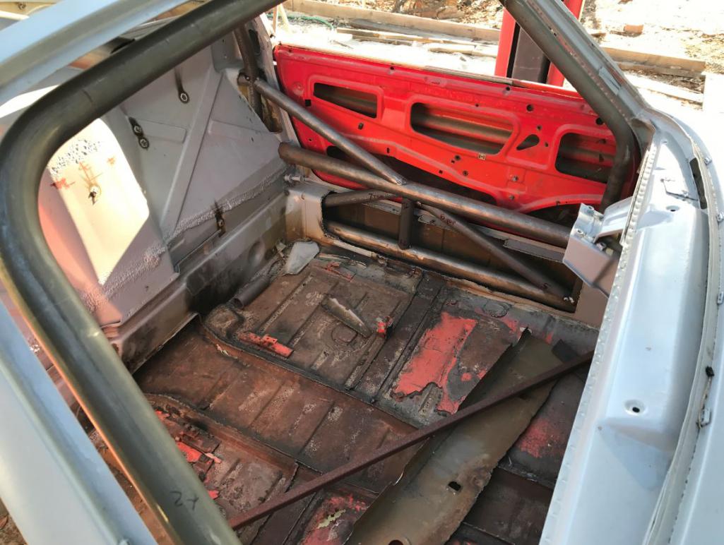
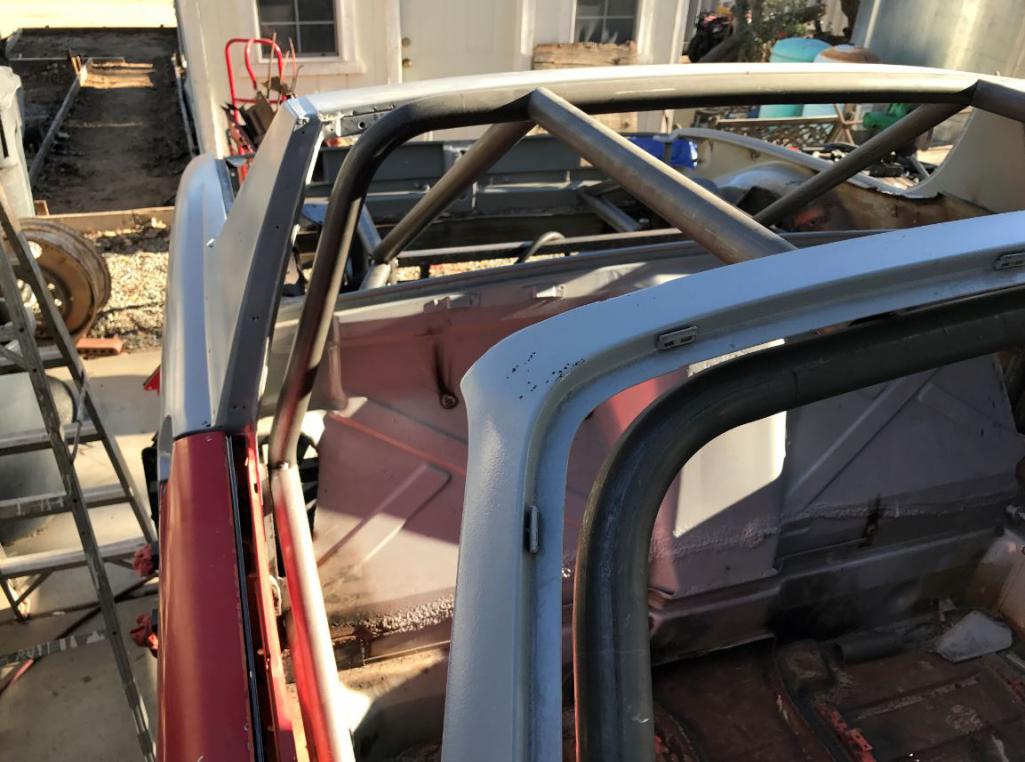
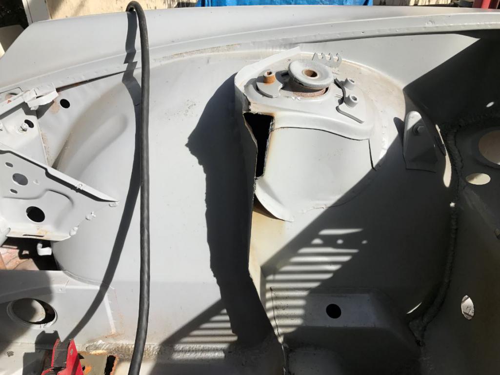
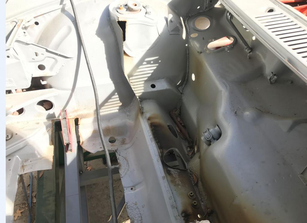
Attached image(s)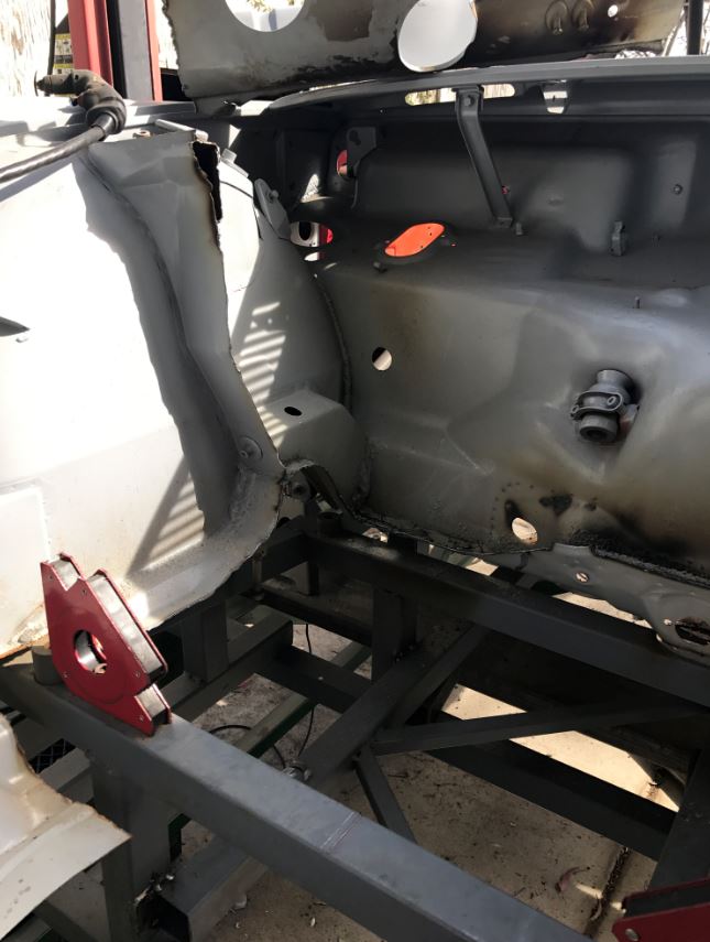
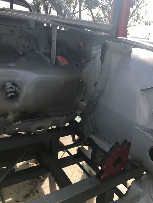
Posted by: tygaboy Nov 15 2016, 03:32 PM
And.........so we start moving to the front of the car.
OK Rudy, at some point, if you keep removing 914 metal, we'll have to require you stop referring to it as "the car"...! Maybe we start a new site for it called "914-ish World"!
Obviously, I'm just jealous and bitter and wide-eyed at your build and your ability to make massive progress each week. Simply awesome.
Posted by: Curbandgutter Nov 16 2016, 03:59 PM
And.........so we start moving to the front of the car.
OK Rudy, at some point, if you keep removing 914 metal, we'll have to require you stop referring to it as "the car"...! Maybe we start a new site for it called "914-ish World"!
Obviously, I'm just jealous and bitter and wide-eyed at your build and your ability to make massive progress each week. Simply awesome.
Thanks for the positive comments......I really appreciate them. I swear "the car" will be undeniably a 914. After this round I need to take the sheet metal off the inside of the rear fenders. The rear quarter panel and back trunk will swing up and back to expose all of the steel tube chassis, aluminum suspension, motor transaxle and 335 rears. I'm hoping to complete the front end today. Then I will move to the 916 flares and body work. Most of the
and  is complete.
 Posted by: csdilligaf Nov 16 2016, 04:16 PM
And you made a nice place to put a fuel cell. I like that.
Posted by: Curbandgutter Nov 16 2016, 07:45 PM
And you made a nice place to put a fuel cell. I like that.
Yep....that is what I meant when you came by and were looking at the front end. It's coming together. I really want to have a roller this month!
Posted by: Cracker Nov 16 2016, 07:50 PM
If you can...use the TT trans.
T
Posted by: Curbandgutter Nov 17 2016, 11:18 AM
Just in case y'all were wondering.......161 lbs of steel have been added and 124 lbs have been cut out. This comes out to a net add of 37 lbs which is basically the weight of an Engman stiffener. At the end of the day it won't be much heavier than a stock teener.
Attached thumbnail(s)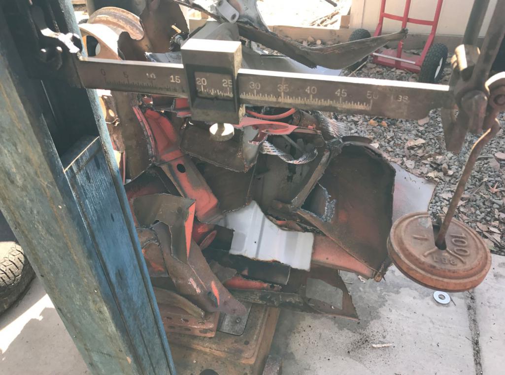
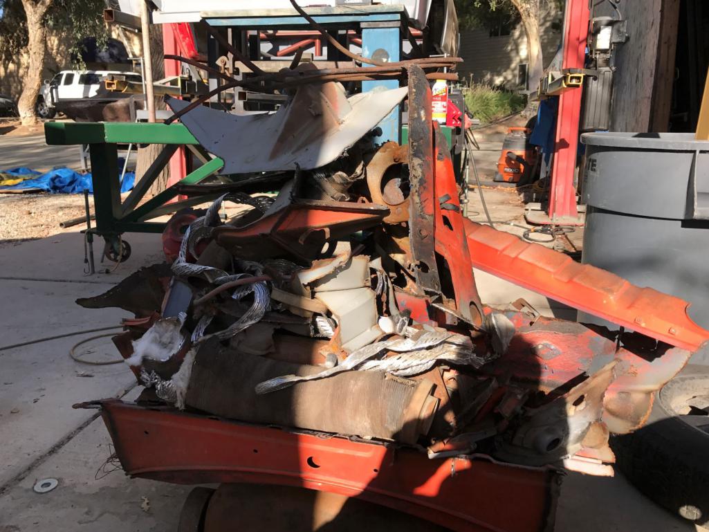
Posted by: Curbandgutter Nov 17 2016, 11:27 AM
Does anyone know the weight savings from :
1) Front Fiberglass Hood (21 lbs)
2) rear fiberglass hood (21 lbs)
3) early doors without the heavy crossbar (23.6 lbs)
4) front fiberglass bumper ??
5) rear fiberglass bumper ??
6) lighter battery (10-15 lbs)
Posted by: sixnotfour Nov 17 2016, 02:41 PM
that's impressive..
just for giggles, have you ever see this build ??
http://www.build-threads.com/build-threads/vw-beetle-porsche-boxster/
Posted by: tygaboy Nov 17 2016, 03:29 PM
Rudy - Don't forget the weight of the kerf on each of the cuts made to remove 914 metal... You're doing even better than you think!
Posted by: Curbandgutter Nov 17 2016, 04:11 PM
Rudy - Don't forget the weight of the kerf on each of the cuts made to remove 914 metal... You're doing even better than you think!
Posted by: Curbandgutter Nov 17 2016, 04:14 PM
that's impressive..
just for giggles, have you ever see this build ??
http://www.build-threads.com/build-threads/vw-beetle-porsche-boxster/
That's too cool! I have actually contemplated on doing a 996 bug with subie sti motor.....thats next after this 914 is complete.
Posted by: Curbandgutter Nov 18 2016, 06:00 PM
Does anyone know the weight savings from :
4) front fiberglass bumper ??
5) rear fiberglass bumper ??
Anyone? Anyone? Buehler...Buehler
Posted by: Mike Bellis Nov 19 2016, 12:40 AM
Does anyone know the weight savings from :
4) front fiberglass bumper ??
5) rear fiberglass bumper ??
Anyone? Anyone? Buehler...Buehler
Not exactly but my FG bumpers are under 10lbs.
Posted by: plymouth37 Nov 19 2016, 10:51 PM
Does anyone know the weight savings from :
4) front fiberglass bumper ??
5) rear fiberglass bumper ??
Anyone? Anyone? Buehler...Buehler
Your work is incredible!
I posted some of my weight savings here:http://www.914world.com/bbs2/index.php?showtopic=84842&hl=
Posted by: Curbandgutter Nov 21 2016, 11:42 AM
Wow, awesome, 26 lb savings with the FG bumpers. Thanks Dane! And what an honor that you think that my work is good. Coming from you that just made my day. By the way, your project was one of the inspirations for my project. I read through every single page and was bummed when you stopped but now am glad to see that you are back on. Thanks for your post.
Posted by: Curbandgutter Nov 21 2016, 11:54 AM
Well wasn't feeling it this weekend wanted to finish the front but was too tired from surveying a project the day before. Anyway here are some pics of the progress.
Here is the reinforcement from the factory that many use to feed water lines through. Notice the crazy amount of sand inside of these? Also....the corrosion. Put some paint inside of these whenever you can.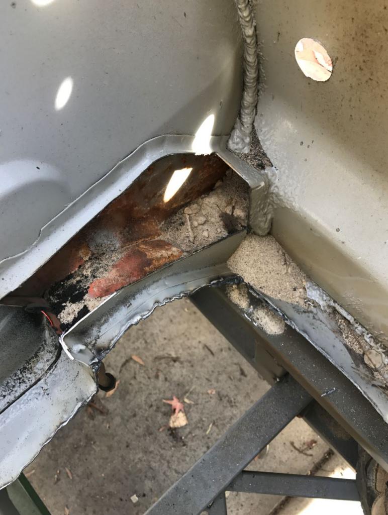
Plenty of room to fit in the front "torsinal stiffener enhancer" 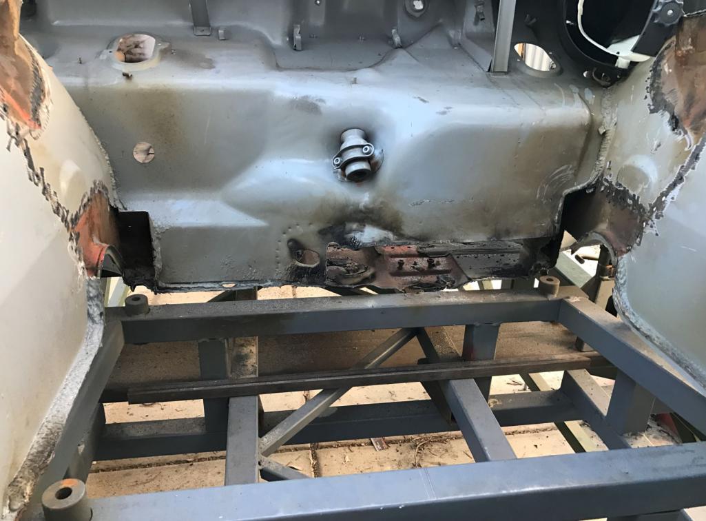
Looks like I need to shorten the strut tower. 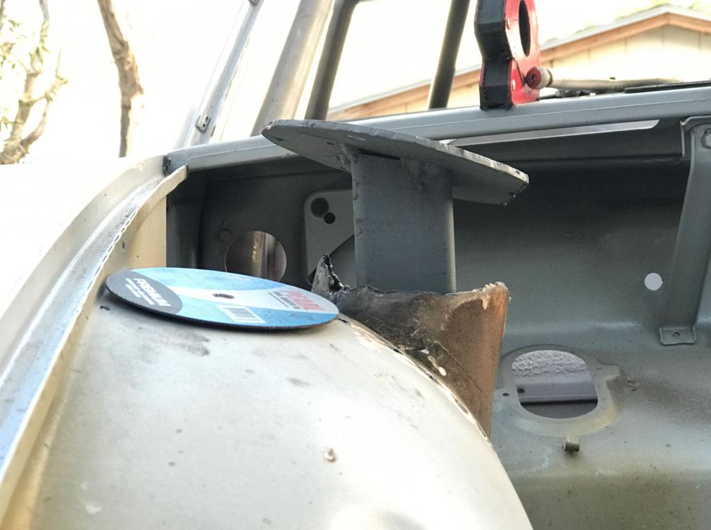
Smokin some briskett 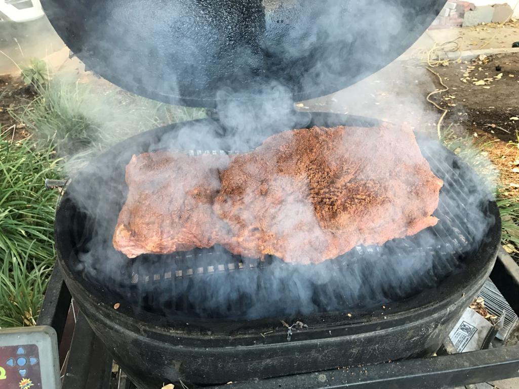
Can you see "the car" in the background 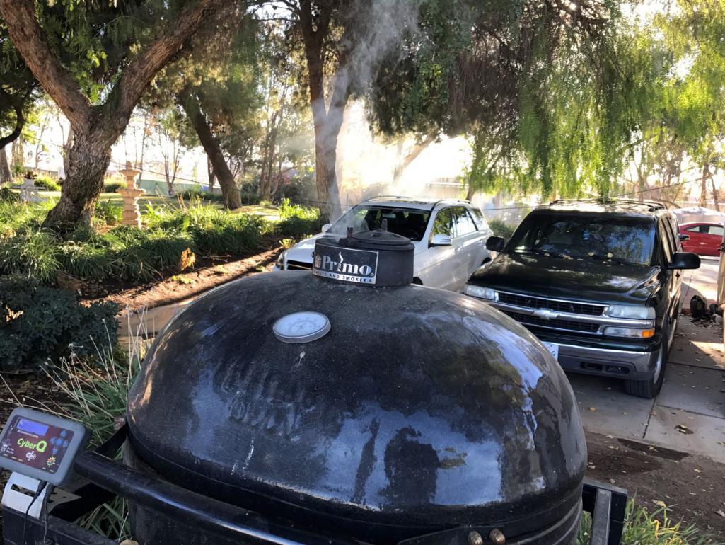
Posted by: csdilligaf Nov 21 2016, 12:23 PM
I wondered about needing to shorten the struts. Yours are already adjustable and may in fact go down enough to fit. I am working on shortening my factory ones first if possible. Hmmm! Brisket looks good!
Posted by: sixnotfour Nov 21 2016, 02:31 PM
your looking right at the solution.. Gurney bubble..maybe not..
I'm hungry
Posted by: Curbandgutter Nov 21 2016, 04:07 PM
I'm not sure if the Gurney bubble would take away from the lines of the 914. But yes it is a solution. However I think that with my coil overs and some machining I may not need the bubbles.
Posted by: csdilligaf Nov 22 2016, 04:03 PM
this is what a Gurney bubble looks like in that location.
Attached image(s)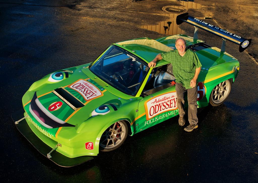
Posted by: Curbandgutter Nov 23 2016, 10:06 AM
I see, pun intended. Not feeling it though. I wonder what suspension that car has that it would need that??
Posted by: Curbandgutter Nov 23 2016, 07:55 PM
So I've been thinking and came to the preliminary hunch/suspicion that I can't just cut the strut tower height without changing the instantaneous roll center. This would be horrible and would affect the dynamics of the car. I'm going to do some calculations and figure it out. However I'm thinking that I may be confined to keeping the struts whee I have them now and then figure out how to implement it into the car. Anybody have some input????
Posted by: FL 000 Nov 23 2016, 08:19 PM
Isn't the instantaneous roll center determined by the upper and lower control arm geometry? If that is the case I would think strut tower height is independent of it.
Posted by: Curbandgutter Nov 23 2016, 11:48 PM
I believe that with the Mc Pherson struts you don't have an upper wishbone. The top of the strut tower is considered the upper wishbone location then you hold a right angle at that location and intersect it with the angle of the lower "a" arm.
see this article
https://balancemotorsport.co.uk/suspension-geometry
It appears that as I lower the strut tower it will raise my roll center. This may not be a bad thing, since depending on where the cg is, it may create a smaller moment arm between the roll center and the center of gravity. If this is the case the car will have less lean in the front end. That may help with creating less understeer. I have to think it through. I have to calc what my cg is up front and then what the 996 roll center is and then what the roll center will be if I lower the strut tower elevation. I need to do some calculations before I make a decision.
Posted by: csdilligaf Nov 24 2016, 10:16 AM
I think shortening the length of the strut along its axis will have much less effect than the article shows when the car is simply lowered. By lowering the car the wishbone angle is changed thus effecting the Roll Center. It does not change all that much if you shorten the strut a few inches with out changing the Steering axis inclination. It will change the Instantaneous Center(virtual Point) and I think the rest would still be the same? But I do not have any strut calculation engine so it is just my gut feeling. I just think it has to end up better than the guys who take a 996 and slam it. It will be interesting to see what your calculations come up with.
Posted by: Curbandgutter Nov 24 2016, 04:28 PM
Shortening the strut will be a step in the positive direction as is will raise the IRC approximately 5/8". Good I wasn't feeling those Gurney bubbles at all.
Posted by: sixnotfour Dec 1 2016, 12:01 PM
Shortening the strut will be a step in the positive direction as is will raise the IRC approximately 5/8". Good
I wasn't feeling those Gurney bubbles at all.your smoker started it.... keep up the build
Posted by: Curbandgutter Dec 1 2016, 04:33 PM
You're looking right at the solution gurney bubble.....smoker just got it.
Posted by: Curbandgutter Dec 6 2016, 11:24 AM
Little update, should be able to finish tying in the front struts to the tube chassis. A couple of progress pics.
Here is the strut attachment point cut down to size. I had to move the tower out and forward to account for the strut inclination angle both sideways and forward and backward. 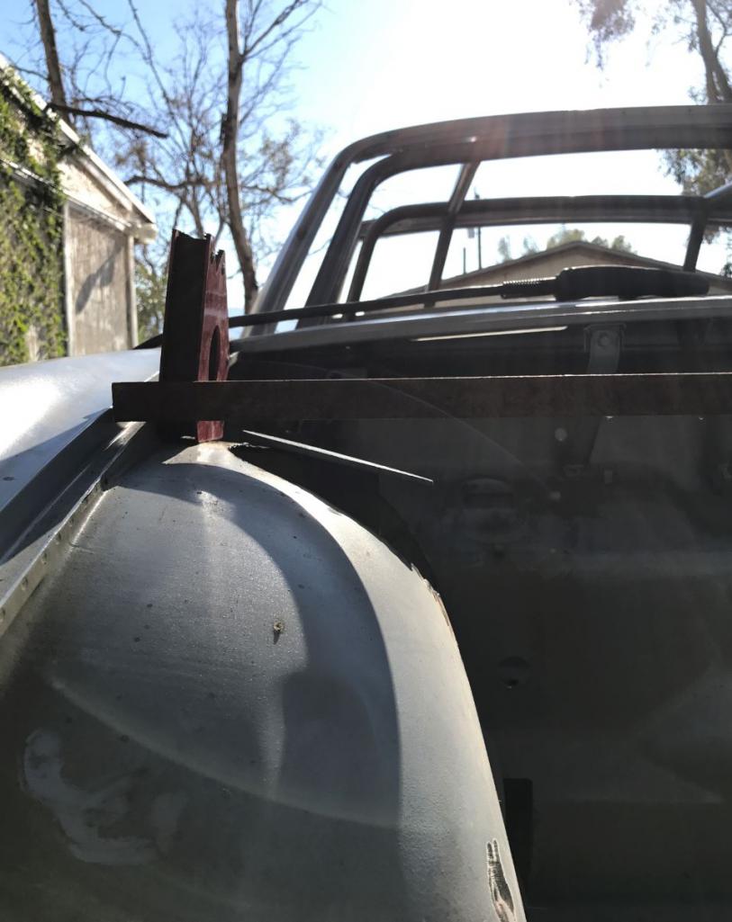
Here is the octagonal shape that I will be using to box int he strut tower 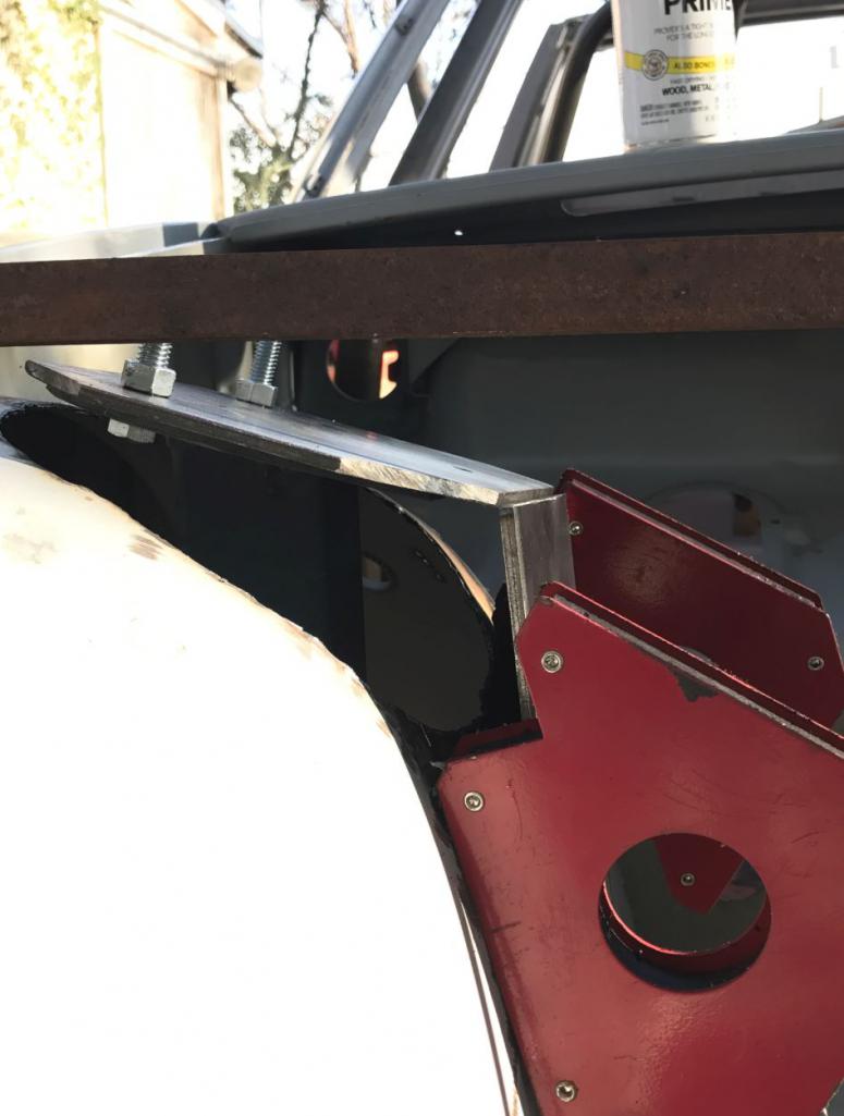
Here is the "strut brace" 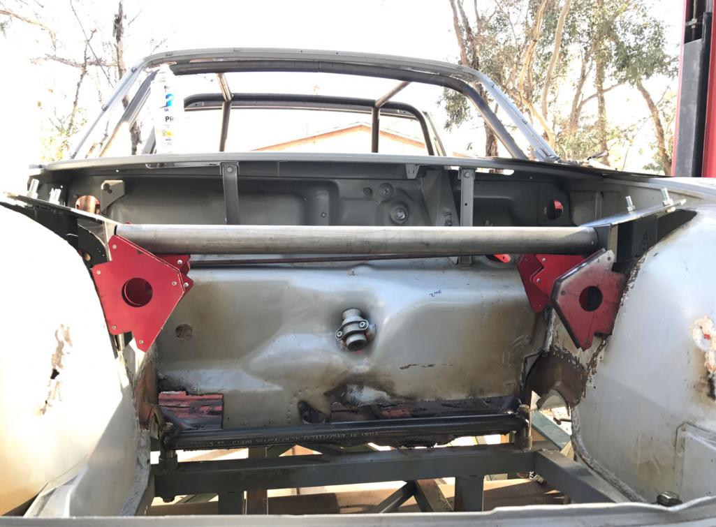
Posted by: Curbandgutter Dec 6 2016, 02:17 PM
Forgot to add this mock up. Test fit of parts before tacking them in. Don't worry the tubes will line up.
Attached thumbnail(s)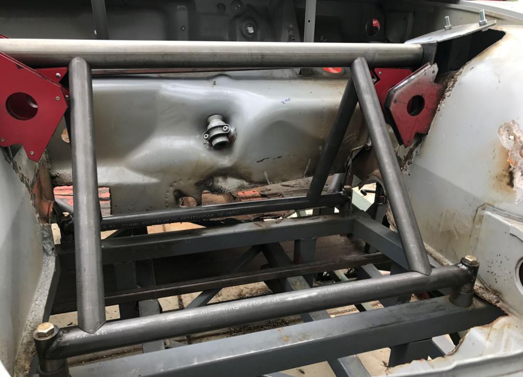
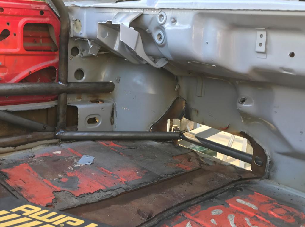
Posted by: csdilligaf Dec 6 2016, 04:01 PM
You know one thing I would like to plan on is moving the driver over a little so you can square up with the pedals. You already are making your own center console box so its a no brainer at this point. The front end progress looks good. Its a big undertaking for sure but your doing an impressive job. Keep it up
Posted by: Curbandgutter Jan 15 2017, 06:45 PM
The weather let up a bit and I was able to sneak in some hours into tying the strut towers in. By the way I am really giving it some heavy consideration into changing engines. I'm leaning to a Audi RS4 Stage 3 motor. It will produce 600 HP so its where I want to be. What do you guys think about that motor choice.
Posted by: Curbandgutter Jan 15 2017, 06:46 PM
The weather let up a bit and I was able to sneak in some hours into tying the strut towers in. By the way I am really giving it some heavy consideration into changing engines. I'm leaning to a Audi RS4 Stage 3 motor. It will produce 600 HP so its where I want to be. What do you guys think about that motor choice.
Attached image(s)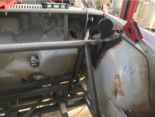
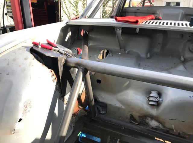
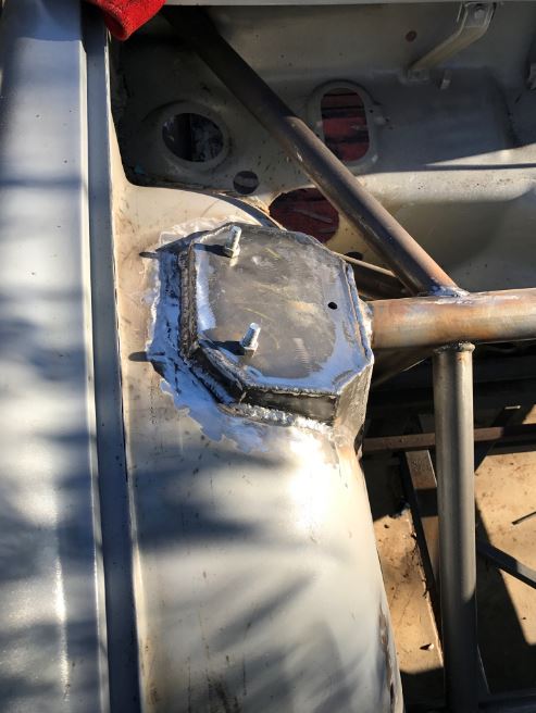
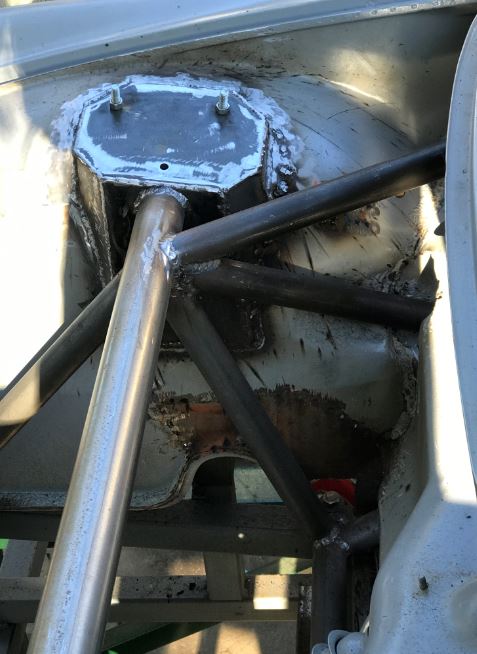
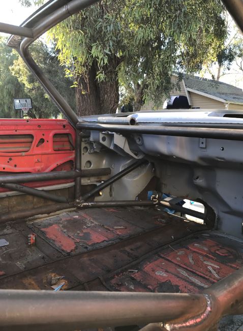
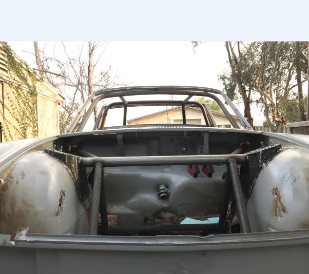
Posted by: tygaboy Jan 15 2017, 07:29 PM
A short passage from a book I think I'll write about Rudy:
"It will produce 600 HP so its where I want to be." He said this casually, as though this level of power was commonplace, even easily attained or available without much planning. He was, as everyone already knew, power hungry. He would come to look at his initial 600hp as "a decent starting point". Eventually, he printed t-shirts with this slogan on the front pocket:
If more is good then too much is just enough!
On the back was printed "I'd rather be sideways".
_________________________
Rudy - I vote "Go for it!"
Your build is looking awesome.
Posted by: Cracker Jan 15 2017, 10:02 PM
You asked Rudy...
I am not a fan of the Audi 4.2 RS4 engine...I saw a nice conversion done into a Boxster race car - very underwhelming. It is low on torque and wasn't competitive either...honestly, I don't care for the sound too. There is a high-price to pay when squeezing big power out of small displacement motors - I know all about them, first hand. Synonymous with hand-grenade.
Remember, you asked!
T
PS: Although both heavy and large - I've thought the GTR TT v-6 would be a nice addition to the 914. Audi have already been done...
PS #2: I'm digging your progress - great job!
Posted by: Andyrew Jan 16 2017, 12:13 AM
4.2 tt rs4 motor? Thats a lot of weight to make that much power.
Its a compact and complicated setup but 600hp is easily made on that setup and it should be extremely torquey.
I think if It were me it would either be the rs4 NA v8 or a S8 4.2 motor for about 360hp to be more economical.
If I wanted to go turbos again with an auto motor I would go 2.7 built with gt28 turbos or KO4 hybrid turbos. That would put a power range from 325-800hp.
Posted by: csdilligaf Jan 16 2017, 08:19 AM
Andyrew, I think you nailed it with the Audi 2.7TT.
Posted by: jd74914 Jan 16 2017, 08:29 AM
Nice strut towers Rudy! They look like really stiff nodes!
The Audi 2.7TT might be a good motor if you want to keep it German. Otherwise a Subaru EG33 or EZ30R with some turbos might work well too-and they'd help lower your CG to boot.
Why are you thinking of moving away from the Coyote? AFAIK they are pretty robust motors to ~650hp (forced induction).
Posted by: Cracker Jan 16 2017, 08:51 AM
I would love to see a small displacement motor - probably a six-cylinder - with quad turbos - since you are ambitious. A target of 600-800 hp at the crank would be fantastic. I have changed my tune on what is "usable in a 914" since my car is so composed with only 590 hp...my car with a 275 rear could hold another 100 easily. Looking forward to what you choose - even if it is an RS4 variant. Cheers.
T
Posted by: Andyrew Jan 16 2017, 09:46 AM
No need for extra complexity with extra turbos. Thats not going to gain power, just response. The 2.7 is plenty responsive with appropriately sized turbos or even just a single turbo like a precision 6262.
The biggest thing to do with turbo cars is pick the right turbo/s for the motor to eliminate boost lag and pick turbos that will efficiently work within the power range your looking for. From there you build the motor to handle the power, make it efficient and then start pumping in boost, timing, and fuel to make power.
My turbo system is a hair lagy but its only a 1.8L displacement, my efficient boost pressure range is 10-35psi letting me tune my boost curve how I want it. I can either turn the timing and boost up down low for the most torque I can make which will blow the tires off as quickly as possible and break things. Or I can give it medium hit and ramp the boost up as it gets higher in the RPM or time in gear to allow for more potential traction yet higher overall acceleration.
Posted by: Cracker Jan 16 2017, 12:32 PM
I do not know Rudy personally (but anyone taking this on - I'd like to meet) but through watching his build (much like Chris too) - it appears he wants to chart new ground - so to speak. The added complexity is the bait to chase - not the obstacle to be avoided - for the rare bird like Rudy that is! JMHO
Twin turbo's, superchargers, vee-eights, etc have all been done adnauseam - a quad turbo set-up on a hot v-6 with DI would be epic. If Rudy isn't that motivated to build something truly unique, I get it. I am not (but it would be otherworldly!)...
T
Posted by: Curbandgutter Jan 17 2017, 11:59 AM
First of all thanks for the replies you guys don't disappoint.
Tygaboy
"If more is good then too much is just enough!
On the back was printed "I'd rather be sideways".
Haha you are crazy. I'm really going to love meeting some of you guys at the events once my car is complete.
Cracker
"I am not a fan of the Audi 4.2 RS4 engine" neither am I. CSDILLIGAF has succeeded into talking me into the Audi 2.7 V6 twin turbo.
jd74914
I thought you'd like those strut towers. I still need to add some gussets. I'm kind of steering away from the coyote for a couple of reasons. The coyote is a great motor but Chip has swayed me into the 2.7 audi because you don' t need adapters and special clutch assemblies. And, I like the way that turbo'd cars pull. Additionally since we will be doing the same exact car, we can brainstorm and have a better chance of success.
I totally understand the CG issue but I just don't like the way that 4 bangers sound.
Cracker
Thanks for the compliments. You and Tigaboy are so hilarious in your writing styles.....I love it. Sorry to let you down though, but no quad turbos, two is enough. I think that the pull on the 2.7 will be enough to give passengers vertigo. I'm hoping that the car will get better traction with a controlled power band up high than down low where it will just cause wheel spin. It's nice to know from real world experience such as yours, that the 914 can handle an additional 100 hp over your 590. Wow that says so much for the amount of performance that is locked up in these little cars that we love. I look at the fact that my car's track is now 5 inches wider, the wheelbase is now 3 inches longer than a stock 914 but 7 inches longer than a 911 and a chassis that will be at least three times as stiff as a 911 and weighing as little as a stock 914, I feel confident that it will not disappoint. It is quite telling that the new 911 is the same wheel base as a 914.
Andyrew
The 2.7 will have the twin RS6 RS turbos.
I'm getting really close to bolting up the suspension. Just need a couple of gussets and the roll bar diagonal and it will be ready for the suspension. Then I'll replace the floor and close up all of the holes I made to insert chassis into the chassis. I will be adding shear connections along the floor pan, the dash and the targa to transfer loads between the chassis plate elements and the tube chassis axial members. In other words tie both chassis together so that they supplement each other where the other is weak.
Posted by: jd74914 Jan 17 2017, 01:04 PM
jd74914
I thought you'd like those strut towers. I still need to add some gussets. I'm kind of steering away from the coyote for a couple of reasons. The coyote is a great motor but Chip has swayed me into the 2.7 audi because you don' t need adapters and special clutch assemblies. And, I like the way that turbo'd cars pull. Additionally since we will be doing the same exact car, we can brainstorm and have a better chance of success.
I totally understand the CG issue but I just don't like the way that 4 bangers sound.
....
I'm getting really close to bolting up the suspension. Just need a couple of gussets and the roll bar diagonal and it will be ready for the suspension. Then I'll replace the floor and close up all of the holes I made to insert chassis into the chassis. I will be adding shear connections along the floor pan, the dash and the targa to transfer loads between the chassis plate elements and the tube chassis axial members. In other words tie both chassis together so that they supplement each other where the other is weak.
As odd as it sounds they are my favorite part of the car!
That makes perfect sense. Using components which are designed from the factory to bolt together is much better. I've personally never been really impressed with the adapter plates/flywheels-too finicky and too unique to the combination. Having two test mules should make it much easier to wring out all of the problems too.
 Equal length headers fix that pesky noise issue...and make the 6's sound like 911's...
 Can't wait to see the shear panels!!
Do you have any ideas on what a 2.7TT dyno plot might look like? Or your gear ratio's/final drive? Just curious as to what the tractive force curve might look like. If you have some numbers I can throw them into a spreadsheet I have and send it to you.
Posted by: Andyrew Jan 17 2017, 01:18 PM
2.7 with RS6's should be a lot of fun. Are you going to get the JHM one's?
https://jhmotorsports.com/shop/catalog/jhm-rs6-rs-turbos-only-for-27t-p-3552.html?cPath=21_56_60_100
What engine management and fuel are you going to go with? We could talk Audi engines all day...
It will be interesting to see how you build the motor, what you do with fueling, engine management, tuning, clutch, ect ect.
The 2.7 is a nice sounding engine, I will give you that
Dyno for comparison. 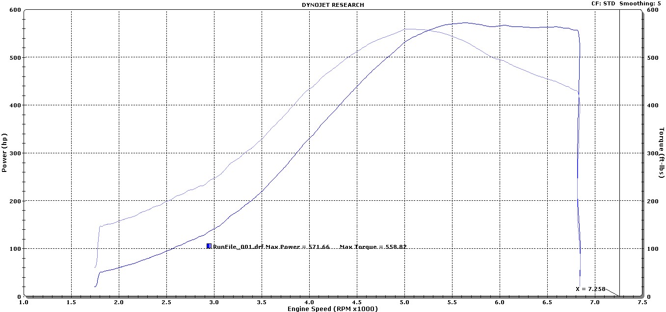
Posted by: Curbandgutter Jan 17 2017, 01:50 PM
Andyrew
Yes the JHMotorsports ones. By the way that looks like it may be the dyno sheet for the JHMotorsports RS6 car? Is that it? From reading your posts and the impressive tuning that you have done it looks like you will be an excellent source of input on the Audi stuff.
JD74914 here are the gear ratios
1st gear 3.307
2nd gear 1.95
3rd gear 1.407
4th gear 1.133
5th gear 0.972
6th gear 0.822
Final drive 3.875
Rear tire will be 335/30-18
Put it in your spreadsheet or if you can, send me the spreadsheet and I'll post the numbers.
Posted by: csdilligaf Jan 17 2017, 01:59 PM
Rudy, the gear ratio's on the G87.21 have taller 1st and 2nd gears as listed on the California Motorsports page. They are 3.307 for 1st and 1.95 for second. That's another reason to use the G87.21.
Plus your tire is a little taller than mine. Yours is 25.9 so you can stretch out the revs more than mine.
Posted by: Andyrew Jan 17 2017, 02:06 PM
Andyrew
Yes the JHMotorsports ones. By the way that looks like it may be the dyno sheet for the JHMotorsports RS6 car? Is that it? From reading your posts and the impressive tuning that you have done it looks like you will be an excellent source of input on the Audi stuff.
Here is where I pulled that sheet from. I have no other info than what he posted. I imagine its wheel HP on C16 or similar since its so high.
http://www.audizine.com/forum/showthread.php/556910-Anyone-seen-dyno-sheets-for-RS6-R-turbos?p=9227384&viewfull=1#post9227384
Posted by: Curbandgutter Jan 17 2017, 02:09 PM
Rudy, the gear ratio's on the G87.21 have taller 1st and 2nd gears as listed on the California Motorsports page. They are 3.307 for 1st and 1.95 for second. That's another reason to use the G87.21.
Plus your tire is a little taller than mine. Yours is 25.9 so you can stretch out the revs more than mine.
Thanks just corrected it.
Posted by: Curbandgutter Jan 17 2017, 11:08 PM
JD74914 I calculated the tractive force based on the Boxter S G87.21 gear ratios and the S4 Stage 3 Dyno plot and this is what I got. Seems like a smooth transition. Looks like Porsche knows what they are doing in selection the gear ratios.
Attached image(s)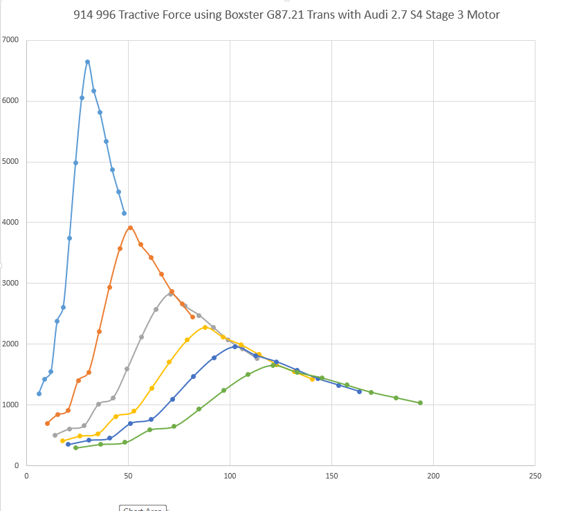
Posted by: jd74914 Jan 18 2017, 06:44 AM
That is a nice smooth parabolic curve-perfect! That's what I've noticed too. If you plot curves from many manufacturers there are some big gaps, but Porsche and Subaru seem to have the gear selection thing down pretty good (for the ideal "go-fast-car" case).
I pulled it last night too and got a very similar curve...sorry I didn't get a chance to post to save you the work. I pulled a number of gear ratios from CM's website and the G87.21 really does seem like a good choice. It's a shame first gear isn't slightly longer, though this seems to be a "problem" in almost all gear boxes (it's really bad in sport bikes).
Copied this from my thread...
Jim, your tractive force spreadsheet proves that if you shift at max torque you will drop the tractive force substantially. It proves that shifting is better near max horsepower. I just did a spreadsheet for my car. Very interesting information. Thanks for illuminating me.
Yeah, it's a rather interesting plot since it brings out things you usually wouldn't think about. It also does a good job of justifying peakier, higher overall power engines vs. these flat torque curve monsters. Glad it could be of use!
Posted by: Curbandgutter Jan 25 2017, 01:23 PM
Finished the strut towers with the gussets that were needed. I should be able to bolt up the full 996 suspension this weekend
Attached thumbnail(s)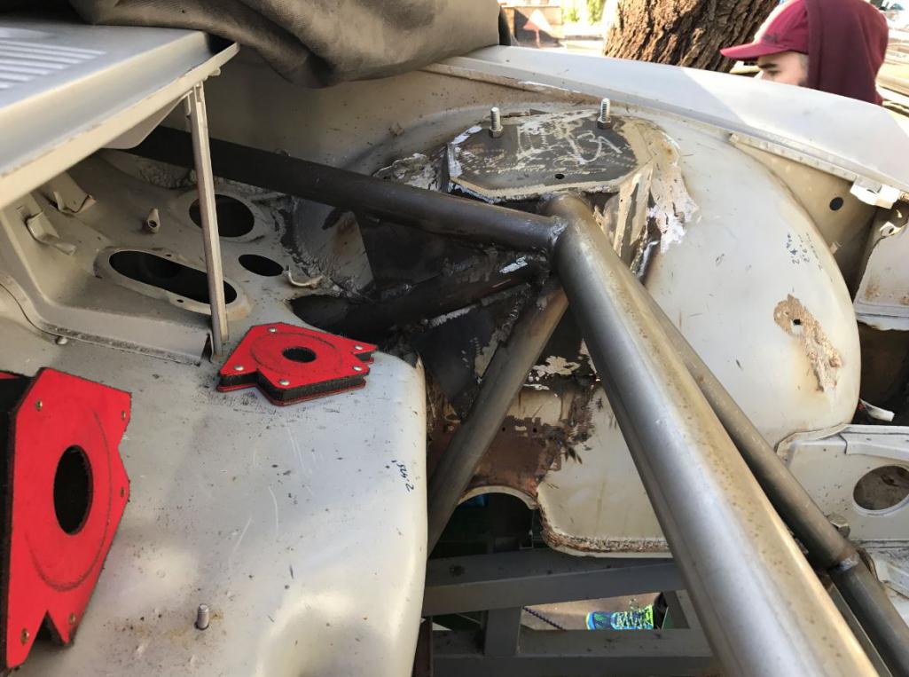
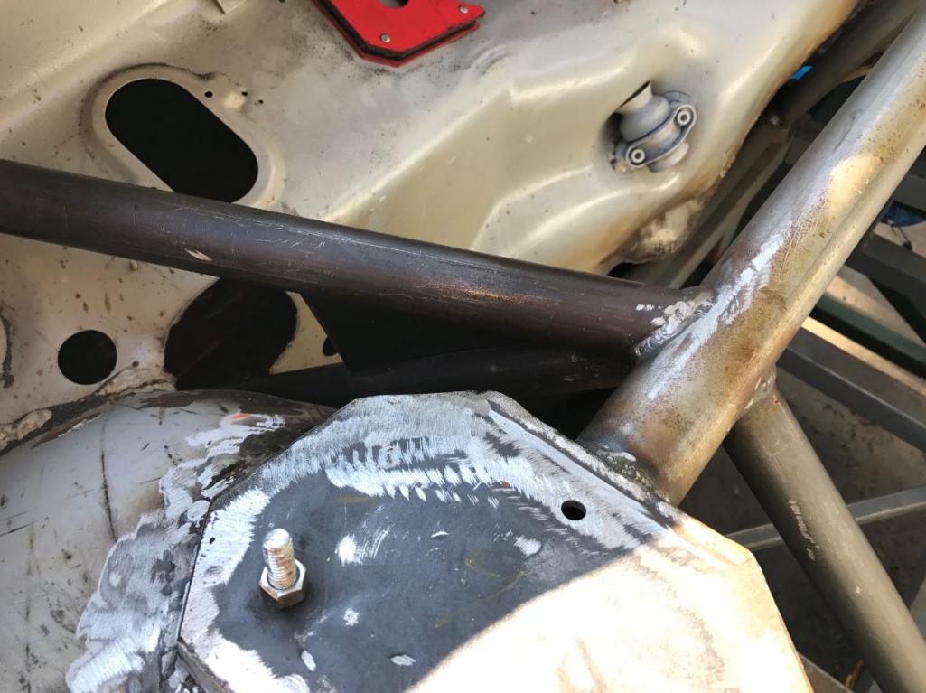
Posted by: tygaboy Jan 25 2017, 02:22 PM
Rudy - That's looking wicked! (that's a good thing...)
Can't wait to see the suspension bolted on and this thing on wheels. I'm waiting anxiously to see the extended wheelbase and how you're planning to mod the body, etc. Any details or plans you can share now? Inquiring minds want to know...
Either way, keep the great work and progress pics coming!
Chris
Posted by: Curbandgutter Jan 30 2017, 12:04 PM
Wow I though that the rear shock towers would take me about an hour each and it took a full 10-hour day to complete both! Anyway here are pictures of the rear shock towers. I took a piece of 6" channel and made a paper template and cut with plasma cutter. Ohh...I'm picking up donor car today. It is a running Audi S4 with 130K miles. Picking it up in Van Nuys tonight. The only major thing left to purchase will be a boxster transaxle. I was hoping to be able to bolt up suspension but that will have to wait until next weekend.
Attached image(s)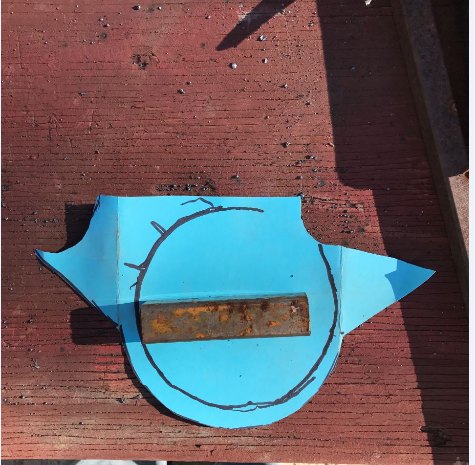
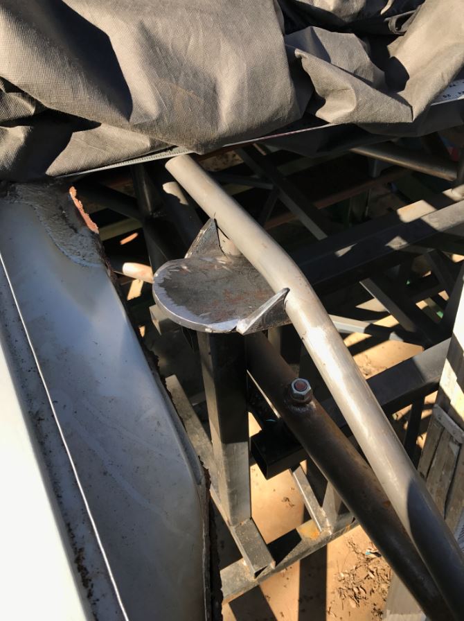
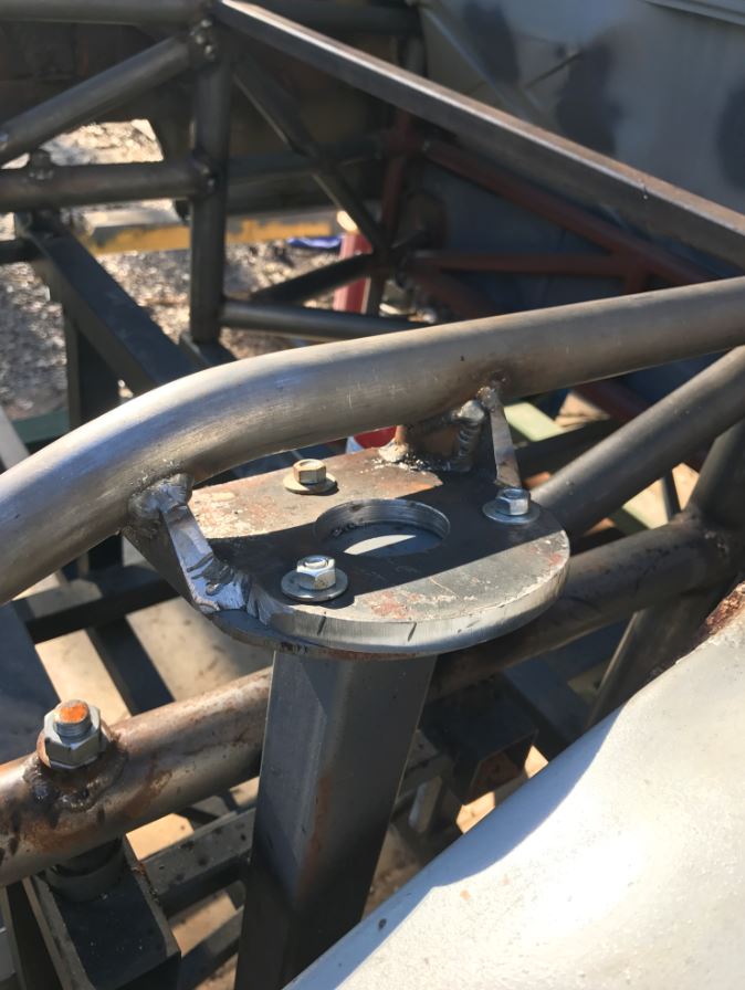
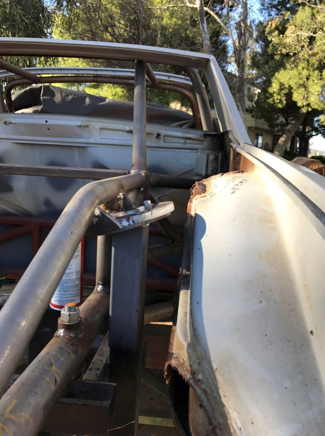
Posted by: Curbandgutter Jan 31 2017, 09:17 AM
The donor has landed.
Attached thumbnail(s)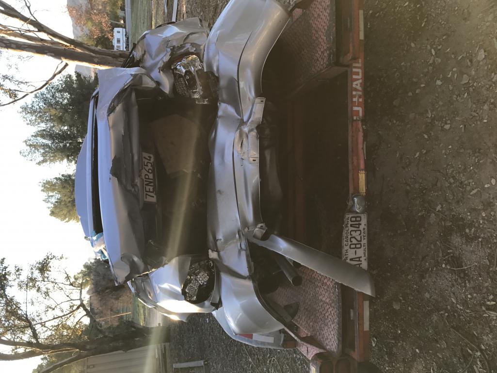
Posted by: tygaboy Jan 31 2017, 09:20 AM
Delete
Posted by: tygaboy Jan 31 2017, 09:20 AM
The donor has landed.
I'll say... and pretty hard, based on that pic!
Keep the coolness coming, Rudy!
Posted by: 76-914 Jan 31 2017, 09:23 AM
Donor car #3? I knew of the 2 Porsche donors. What is the Audi donating?
Posted by: Curbandgutter Jan 31 2017, 10:11 AM
996 donated the legs and feet. Donor 914 donated moral support. Audi S4 is donating heart and lungs.
Posted by: csdilligaf Jan 31 2017, 10:21 AM
My Audi Donor was the same way. A little love tap in the back end leaving a perfectly good running 2.7TT up front.
Posted by: Curbandgutter Jan 31 2017, 10:50 AM
Yep exactly! Drove it right up onto the trailer. Fires right up.
Attached thumbnail(s)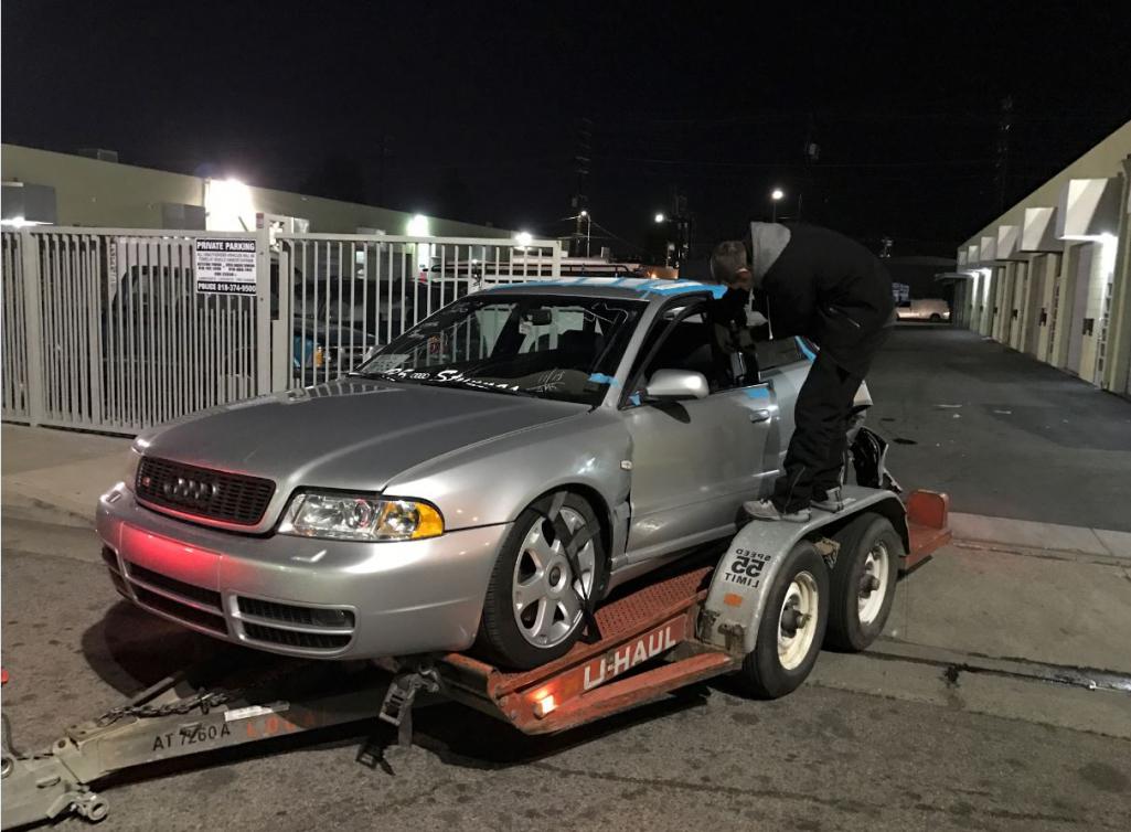
Attached image(s)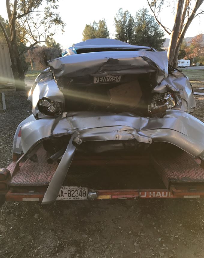
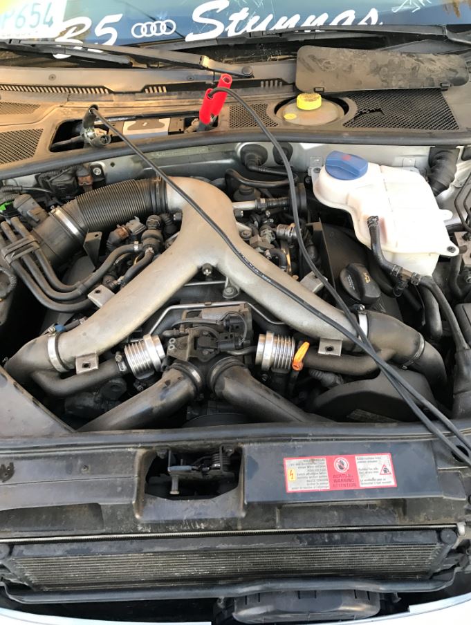
Posted by: Mark Garriott Jan 31 2017, 11:07 AM
What are your plans for intercooling -- air/air or water/air?
Posted by: Curbandgutter Jan 31 2017, 11:17 AM
For simplicity ( I know it's an oxymoron for this build) I am going to use the factory setup. I think that it is air/air. Since I am planning to open up the back end 2 1/2" on each side to accommodate the wider 996 track, I will take advantage of that and place an intercooler on each side but most likely 50% larger and mounted vertically. I will fold the rear 1/4 panel into them and create a reverse scoop to drag air into them. I plan on venting out through the rear in between the tail lights with some type of expanded metal. Maybe like the one that is on the engine lid.
Posted by: Andyrew Jan 31 2017, 11:55 AM
Factory intercoolers are air to air and are not very efficient. They make thicker intercoolers specifically for the S4, specifically chineese versions that are very affordable. Combine that with E85 or W/M injection and you should be good for a considerable amount of HP.
I would go something a hair larger like this if your considering staying air to air.
http://www.ebay.com/itm/Rev9-Turbo-Side-Mount-Bolt-On-Intercooler-For-300zx-Z32-90-96-Fairlady-Z-VG30-/381440476746?hash=item58cf9fc64a:g:zAMAAOSwAYtWIXMO&vxp=mtr
But you would probably be better off going with a pair of bar air to water intercoolers and just mount a single large radiator in the fender.
http://www.ebay.com/itm/Liquid-Air-Intercooler-13-5-x-4-x-3-5-2-5-In-Out-Long-Flow-Turbo-Water-/152405790687?hash=item237c17cfdf:g:MzsAAOSwLEtYhC7z&vxp=mtr
Posted by: Andyrew Jan 31 2017, 12:01 PM
Noticed forged diverter valves, Thats a plus
Pull the ECU and see if there are any markings on it. I bet at the very least this car was tuned, probably sell that ecu for an easy buck if your going a custom engine management system.
Posted by: csdilligaf Jan 31 2017, 12:22 PM
There really is not an affordable option for a stand alone engine management for this motor. There are people who tried with a $5K version or more and had nothing but trouble and never got it to work right. We want to build a car, not take a year to learn what others already know and are good at. The factory ECU has a huge following and tuners with the education and skill it takes to hack and do what ever you want are plentiful. I have found Motoza Performance to be the best, easiest, most helpful and cost effective. For around $400-$500 they give you the software to reflash the ECU, the cable to do so from a laptop and OBD2 port and the first version with the basic tune. This allows you to get up and running and run the data logging that gets emailed to them and they will tweek things until you are happy. If later you go up to bigger turbo's or go to E85 you just pay the difference of the two stages pricing and they help you out again.
Posted by: Curbandgutter Jan 31 2017, 12:46 PM
Andrew thanks for your input. But yes we're sticking to stock engine management with tuners that work with them. Thanks for the info on those forged diverter valves, I didn't think they were stock but really didn't know what I was looking at. I have a lot of learning to do on this motor. I'm glad you're around so that I can glean information from you. As far as intercoolers im thinking of going with this company http://bellintercoolers.com/how-to-order/core-inventory/3-00-core-thickness-airair/
Posted by: Curbandgutter Jan 31 2017, 01:08 PM
Ok so now I'm the owner of a Cayman S G87.21 transaxle. Should be here by Feb 6th. Well looks like I'll be pretty busy from here on.
Attached thumbnail(s)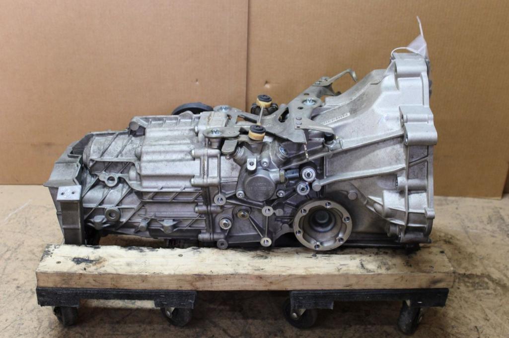
Posted by: Andyrew Jan 31 2017, 01:15 PM
Megasquirt has been effectively utilized on that motor, but I agree the factory ECU is more than capable. I am utilizing the factory ECU as well and know it has and will support my setup just fine as I ramp up the power.
Seriously pull the ECU, Most tuners will mark it. You might find it tuned by a reputable tuner who will set you up on a big turbo file and give you advice on what you need injectors, fuel pump, maf, ect ect.
Custom intercooler is a fantastic way to go on a project of this nature. If you have the ability to weld aluminum I really think you should build a twin air to water intercooler setup in front of the engine (you will have plenty of room).
This will allow you to keep the intake plumbing short and in the engine bay vs having to shoot to both sides of the fenders. Should help with spool as well.
Posted by: Andyrew Jan 31 2017, 01:16 PM
Ok so now I'm the owner of a Cayman S G87.21 transaxle. Should be here by Feb 6th. Well looks like I'll be pretty busy from here on.
Looks nice. Going to get a LSD for it? What did you pay for it?
Posted by: Curbandgutter Jan 31 2017, 01:20 PM
Yes LSD from CMS motorsports. Chip already had his done. Paid $1650
Posted by: jd74914 Jan 31 2017, 01:24 PM
As far as intercoolers im thinking of going with this company http://bellintercoolers.com/how-to-order/core-inventory/3-00-core-thickness-airair/
You can't go wrong with anything from Bell. If you need technical support Gerhard Schruf is awesome! I've bought air-to-air and air-to-water intercoolers from them a few times (industrial usage but really no difference from automotive) and their prices really aren't too bad considering the quality.
Posted by: csdilligaf Jan 31 2017, 06:04 PM
CMS motorsports sells and installs the Wavetec LSD. They are $1255 plus install. Everyone has good reviews of it and it is made in the USA so I will give it a try. I have always had Quaife so the Wavetec will be new for me. Anyone have personal experience with them?
Posted by: Curbandgutter Feb 3 2017, 05:50 PM
Well tranny came in today. Lifting car off of jig tomorrow. Will do a twist test before installing suspension. Huge milestone
Posted by: Cracker Feb 3 2017, 05:59 PM
Good for you...congratulations!
T
Posted by: Curbandgutter Feb 4 2017, 03:58 PM
Well she's off the jig. Im going to try and do the twist test today. However, I have to smoke a briskett for the super bowl so the twist may have to wait.
Attached image(s)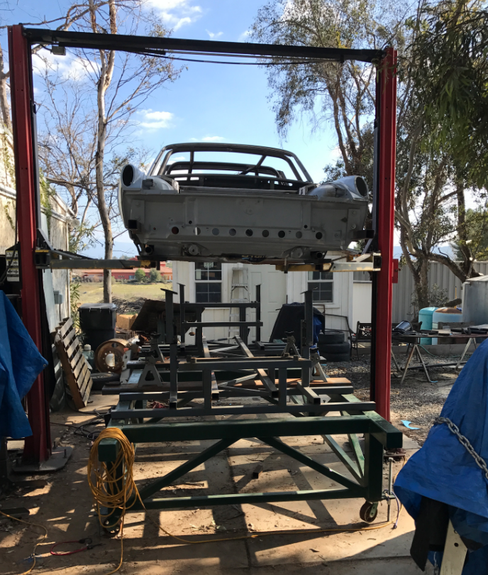
Posted by: Curbandgutter Feb 4 2017, 06:53 PM
Bolted up rear suspension. After everything is dialed in, I will bead blast the entire suspension and powder coat the calipers in red.
Attached image(s)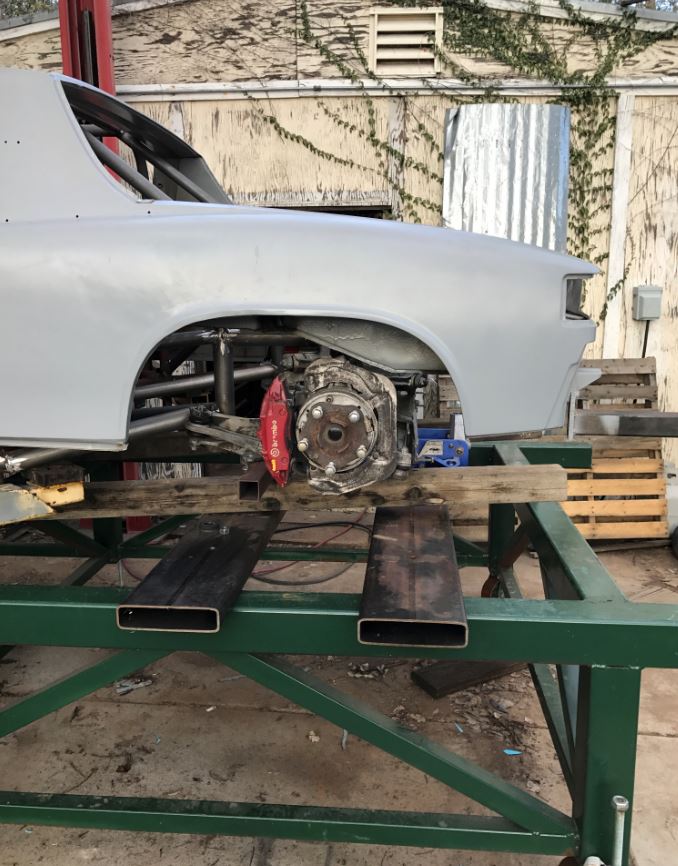
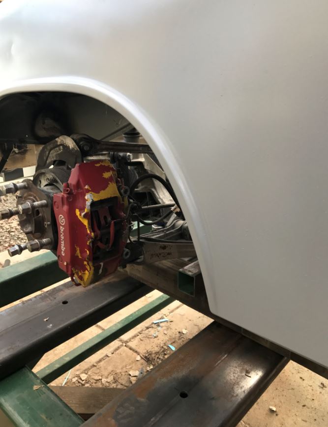
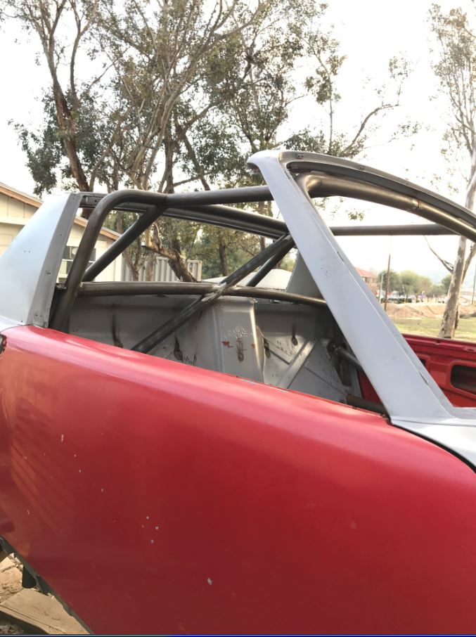
Posted by: csdilligaf Feb 6 2017, 03:33 PM
Looks like you stretched the wheel base just the amount you wanted too. Looks good. And the one tube you thought would be close at on the rear suspension looks like it just cleared. Can wait to see it on the ground with wheels and tires.
Posted by: tygaboy Feb 6 2017, 04:28 PM
Looks like you stretched the wheel base just the amount you wanted too. Looks good. And the one tube you thought would be close at on the rear suspension looks like it just cleared. Can wait to see it on the ground with wheels and tires.
and I'm going to take a wild guess that csdillgaf and I aren't the only ones who're chomping at the bit to see this bad boy as a roller. So, Rudy, hurry the hell up! We want video of you sitting in it, on a milk crate, steering wheel in hand (bonus points if it's not even mounted on the column) doing your best impression of turbo flutter/blow-off valve/waste gate noises!
Come on, we're waiting:
And of course you know what I really mean by all this idiocy: LOVE your build!!! Can't hardly wait to see the progress each post.
Chris
Posted by: Curbandgutter Feb 6 2017, 07:18 PM
Thanks guys, I know what you mean I feel the same way. Just picked up a set of rims and tires so that I can use on the "roller". I didn't want to roll on the Rivieras so I picked up these 996 Hollow Spoke Turbo Twist wheels. They are 18x8.5 F 18x11 R.
Attached image(s)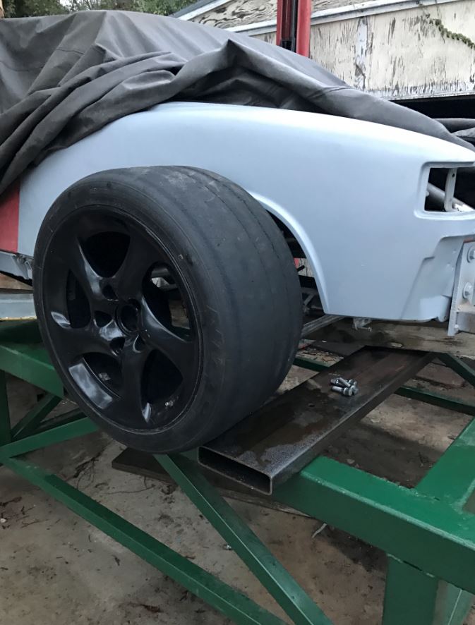
Posted by: Andyrew Feb 6 2017, 09:06 PM
Mmmm good choice of wheels
Posted by: Curbandgutter Feb 7 2017, 08:31 PM
Well I have half a roller. Tomorrow I hope to bolt up front. Will be rolling by saturday. I'm really digging how the car looks with the extended wheel base. It puts the rear tire closer to the rear bumper and gives it a more cat like stance. I can't wait!!!!
Attached thumbnail(s)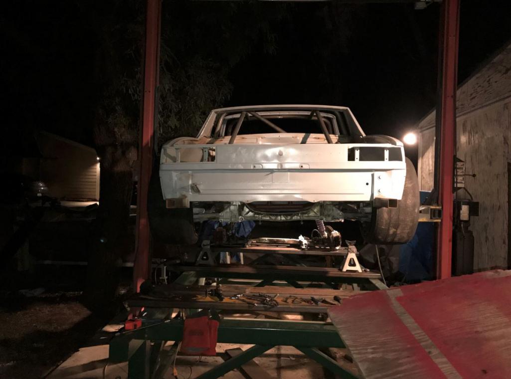
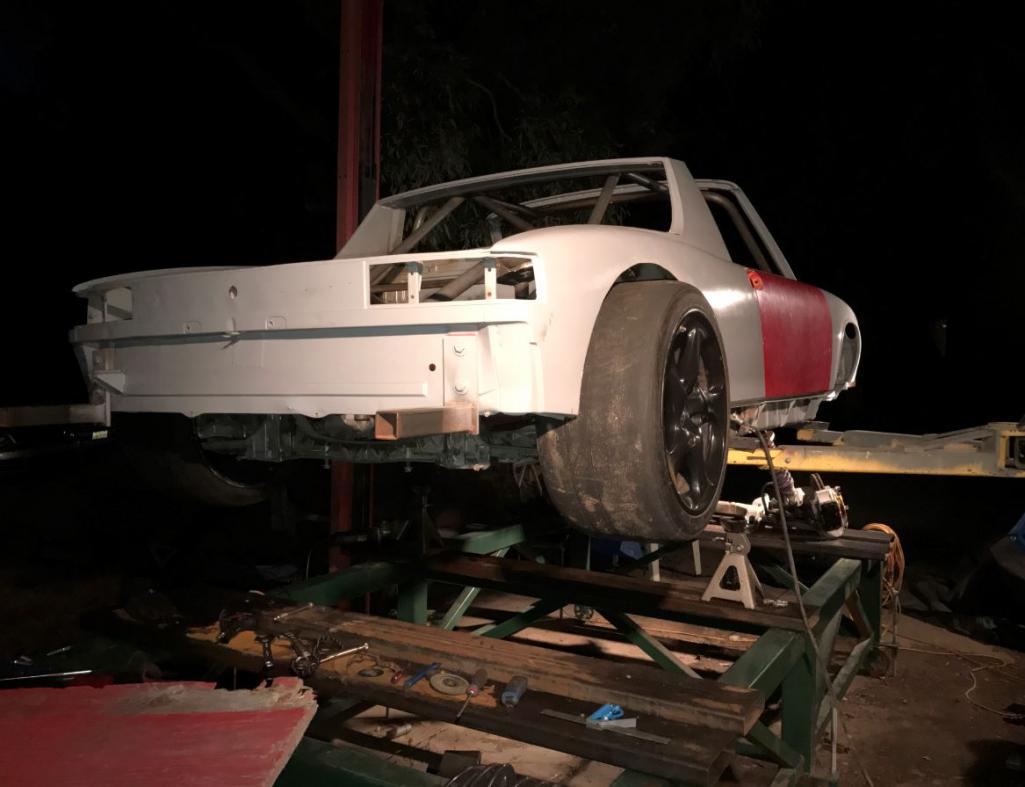
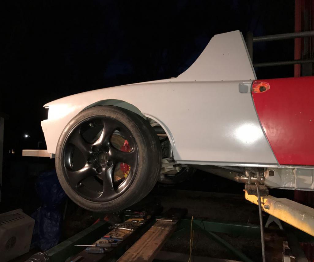
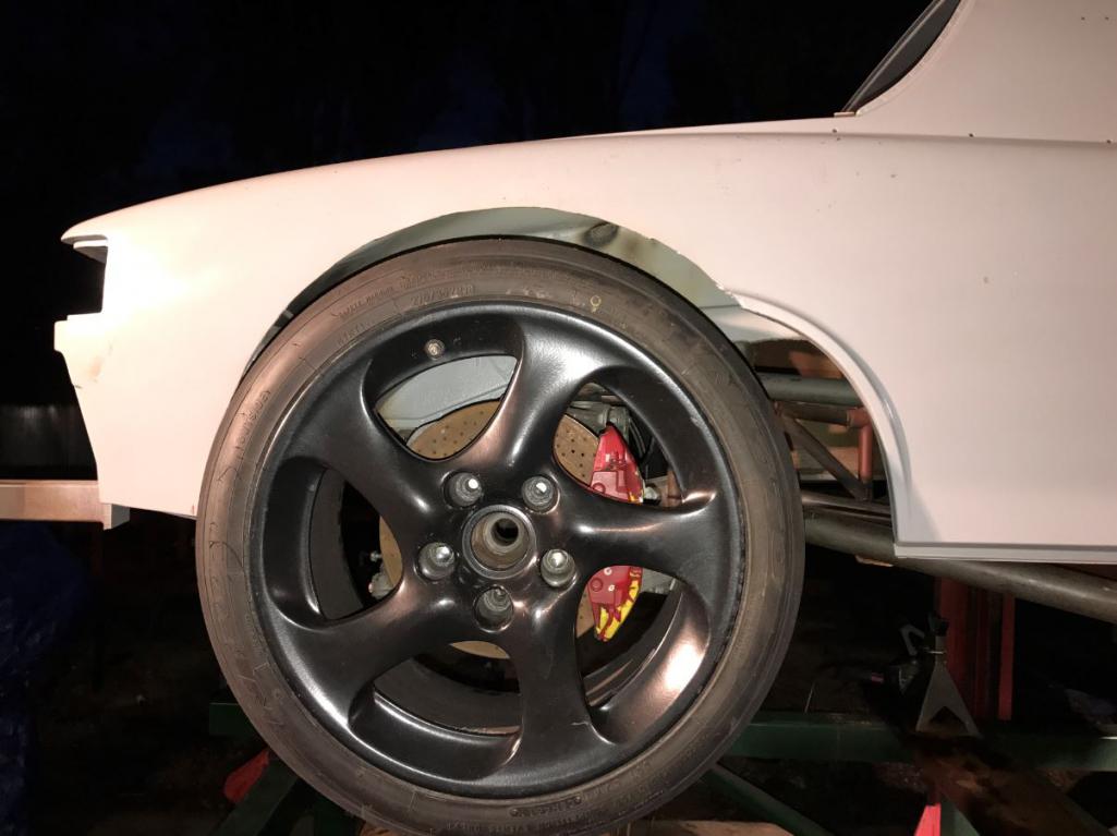
Attached image(s)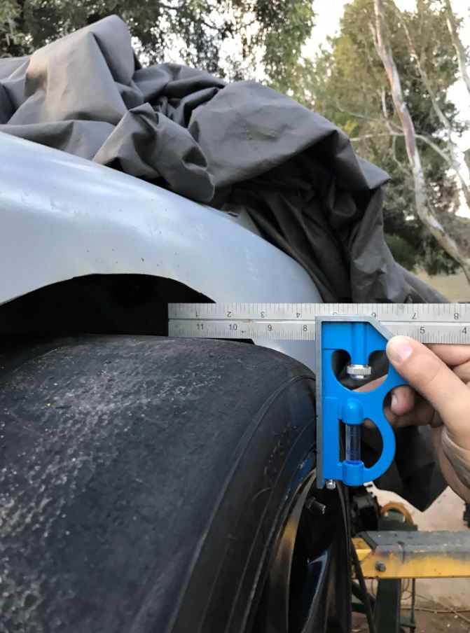
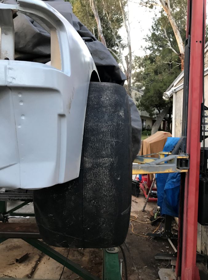
Posted by: Curbandgutter Feb 7 2017, 09:30 PM
I need to update the title of this build! Anyone know how?
Posted by: Andyrew Feb 7 2017, 10:16 PM
Edit your first post, up top there will be the ability to edit the header. (Full Edit)
Posted by: tygaboy Feb 7 2017, 10:37 PM
Rudy - you need some "body" to go with that "wide"!
Looks killer. What are your plans for the flares?
Posted by: Mueller Feb 8 2017, 09:36 AM
Rudy - you need some "body" to go with that "wide"!
Looks killer. What are your plans for the flares?
I vote for mudflaps!
Seriously, awesome progress!
Posted by: AZBanks Feb 8 2017, 07:31 PM
Rudy - you need some "body" to go with that "wide"!
Looks killer. What are your plans for the flares?
I vote for mudflaps!
Seriously, awesome progress!
I second the call for mudflaps. It has a really cool dirt track modified look going on. You should keep it as is with some mud flaps.

Posted by: Curbandgutter Feb 8 2017, 09:55 PM
Its going to have mudflaps like these.
Attached image(s)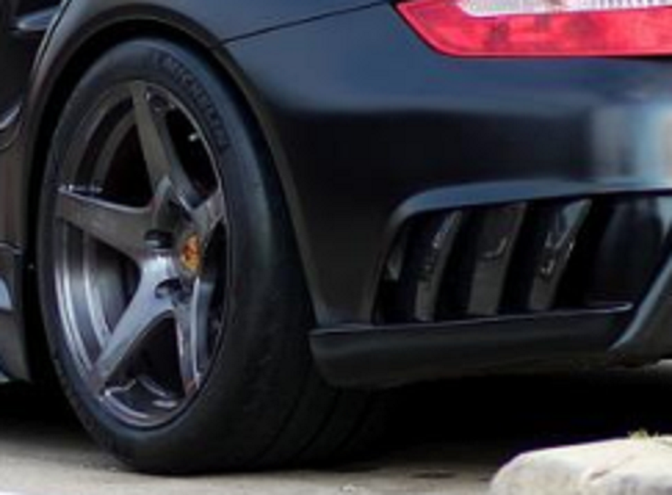
Posted by: Curbandgutter Feb 12 2017, 06:22 PM
WE GOT A ROLLER!!!!!!!!!!!!!!!!!!!
Attached thumbnail(s)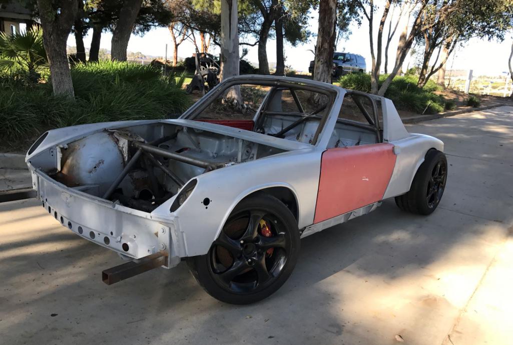
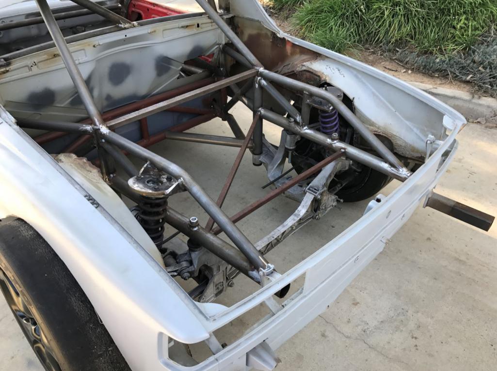

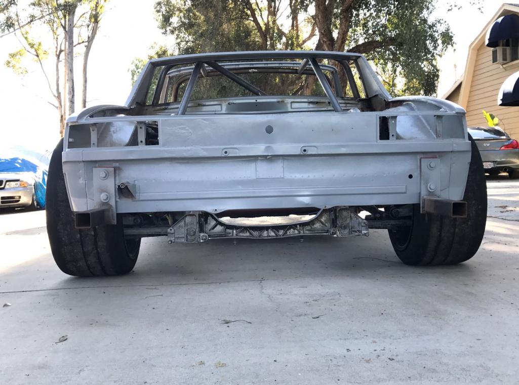
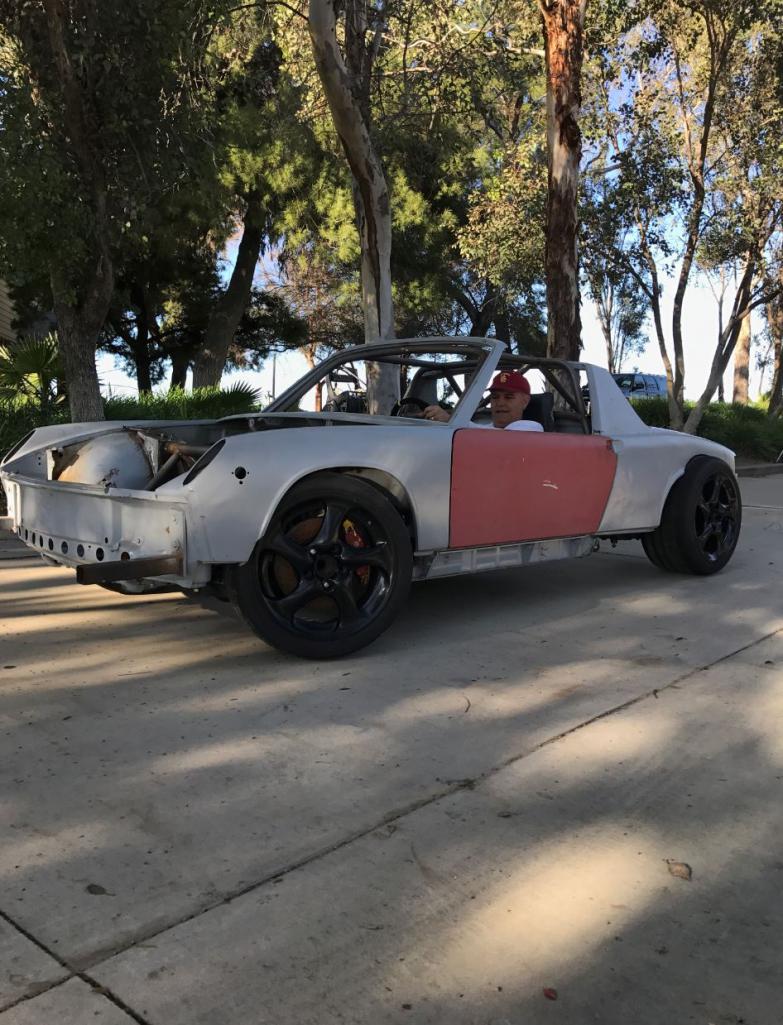
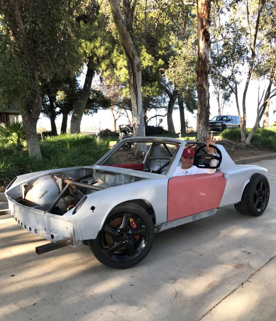
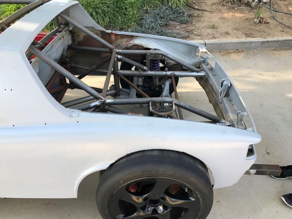
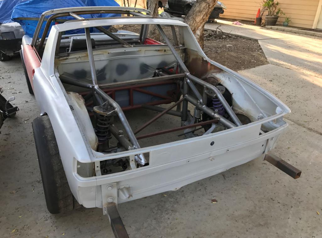
Posted by: tygaboy Feb 12 2017, 06:29 PM
Sorry, I don't see the milk crate so no points...
Seriously - what a COOL look! You have to be totally psyched to have it on wheels.
Congrats on a major milestone!!
Posted by: Andyrew Feb 12 2017, 07:17 PM
Looks fantastic!! Congrats!
Posted by: csdilligaf Feb 13 2017, 08:36 AM
Way to go Rudy!!! I knew on Sunday with no rain you would be up there working on it. I am digging' those wheels on it. And the Momo Steering wheel is a nice touch.
Posted by: jd74914 Feb 13 2017, 11:33 AM
Sweet!! That's awesome!! Can't wait to see it at ride height with some flares!
Could you take a side profile shot? I'm just curious to see how far the rear wheels really are back.
Posted by: Curbandgutter Feb 13 2017, 06:49 PM
Sorry, I don't see the milk crate so no points...
Seriously - what a COOL look! You have to be totally psyched to have it on wheels.
Congrats on a major milestone!!
Totally psyched. Its a really good feeling to see it on the ground.
Posted by: Curbandgutter Feb 13 2017, 06:51 PM
Looks fantastic!! Congrats!
Thanks Andrew.
Posted by: Curbandgutter Feb 13 2017, 06:52 PM
Way to go Rudy!!! I knew on Sunday with no rain you would be up there working on it. I am digging' those wheels on it. And the Momo Steering wheel is a nice touch.
Thanks Chip. Damn right I was going to be working on it. Thanks to you, I was able to get the wheels. Yes that Momo was a Christmas present.
Posted by: Curbandgutter Feb 13 2017, 06:54 PM
Sweet!! That's awesome!! Can't wait to see it at ride height with some flares!
Could you take a side profile shot? I'm just curious to see how far the rear wheels really are back.
I can't either. Flares are going to wait a little bit since I want to install motor and tranny and I still have to do the twist test.
Attached, just for you, is a profile showing the "extended wheelbase"
Attached thumbnail(s)
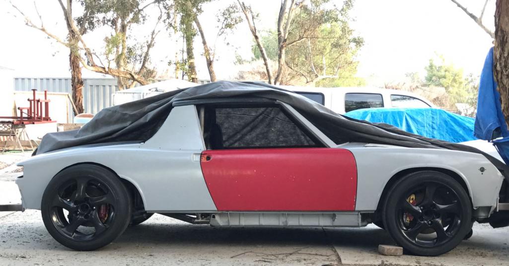
Posted by: calilumber Feb 15 2017, 06:38 PM
Lets go, start dropping in trans and that Audi is not gonna pull its own engine!
Posted by: csdilligaf Feb 22 2017, 09:52 AM
I just got back from California MotorSports in Lake Havasu Arizona after having them install the Wavetech LSD in the Cayman S 6 speed. I have been working on mating the trans and engine so Rudy and I know what to expect. If I work out those details it will speed along the process for him and he can focus on other parts of the build.
I have a Fidanza aluminum flywheel and an RS4 clutch package. First there is a 1" thick spacer on the crank face of engines that came from an Automatic equipped car, I put steel rod in the holes and tapped it a little while going from hole to hole, popped right off. Warm up the flywheel so the hole grows enough to slip over the crank locating boss. The bolt holes will only line up one way, they are not equally spaced. If you warm the flywheel to about 180/200 degrees on a hot plate it will give you time to align it with a bolt or two before it tightens up. Use the 1mm thick shim from the automatics flex plate in the same location under the bolts to prevent galling and help torque to correct specs.
I will make a drill fixture plate with bushings so that three stud holes can be drilled and tapped along the bottom of the G87.21 trans making it fully bolted to the Audi 2.7T.
It appears that the Cayman S trans has a boss that needs to be drilled out for the crank sensor. The boss is in the same location as the Audi manual transmission and I have seen it done on an Audi swap into a Boxster S in the UK.
We will need to use the transmission spacer from the Audi automatic trans that is 7/16" thick. The RS4 clutch disk fits on the Cayman S spline and the pilot shaft fits into the pilot bearing perfectly.
Now we just need to figure out the Vehicle Speed Sensor. Maybe something mounted on the CV joint. It is a magnet pulse type. Rudy has one from his parts Audi and I purchased the sensor and the pulse ring new. The pulse ring is smaller than a CV joint so we may have to try and replicate the pulse some how. Any electrical engineer types out there that know how to figure it out? Here is the basics of it.
http://forums.quattroworld.com/s4s6/msgs/228211.phtml
Maybe we can adapt the 996 abs sensor and reluctor ring to duplicate the pulse?
Attached thumbnail(s)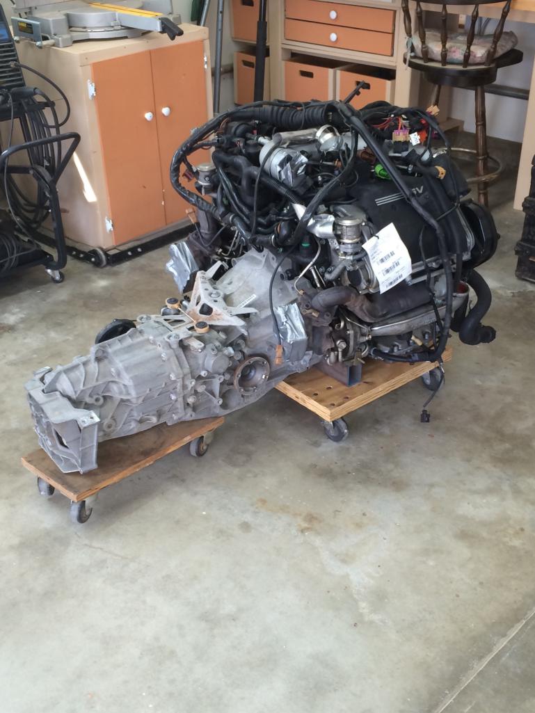
Posted by: Andyrew Feb 22 2017, 10:01 AM
Regarding your clutch. A standard B5 RS4 clutch isnt the hot ticket now adays. Apparently the B7 clutch pressure plate is that much better. This might require a custom flywheel, check into the S4 forums to find out what they are doing. If I swapped out my clutch again ( I have a stage 3 S4 clutch) I might go this route.
Regarding your VSS You could simply count the pulses on the stock VSS pickup, fab up that many 1/8-1/4" steel teeth and weld them onto your CV flange, then fab a mount for the VSS.
Posted by: csdilligaf Feb 22 2017, 10:27 AM
It may not be the hottest ticket but I think it will hold the power for now and was cheap. Now Rudy may want to look into that because I know he will be looking for more power than me. I will be at 375/400 with 550cc injectors and Ko4 turbos on E85. And may still have to go with something like the stage 3 like you have now. I just really like the ease of a build that is bolt together with no custom and expensive parts.
I have done the flange modification you mentioned for the VSS but it was on an LS swap and the sensor had the magnet in it and was an easy set up to do. It looks to me like the Audi VSS has the magnetic pick up in the reluctor wheel and if flips from North to South? I suppose I could use magnets in the flange this time and just flip them according to push and pull magnetic field?
Posted by: jd74914 Feb 22 2017, 10:45 AM
Now we just need to figure out the Vehicle Speed Sensor. Maybe something mounted on the CV joint. It is a magnet pulse type. Rudy has one from his parts Audi and I purchased the sensor and the pulse ring new. The pulse ring is smaller than a CV joint so we may have to try and replicate the pulse some how. Any electrical engineer types out there that know how to figure it out? Here is the basics of it.
http://forums.quattroworld.com/s4s6/msgs/228211.phtml
Maybe we can adapt the 996 abs sensor and reluctor ring to duplicate the pulse?
I'm very surprised it's a magnetic ring. It looks like the magnets close a reed switch so to produce a square wave, so you could likely switch to a hall effect gear tooth sensor and use an 8 toothed wheel added to the outside of your CV boot, etc. rather than add magnets to something.
Posted by: Andyrew Feb 22 2017, 10:55 AM
Now we just need to figure out the Vehicle Speed Sensor. Maybe something mounted on the CV joint. It is a magnet pulse type. Rudy has one from his parts Audi and I purchased the sensor and the pulse ring new. The pulse ring is smaller than a CV joint so we may have to try and replicate the pulse some how. Any electrical engineer types out there that know how to figure it out? Here is the basics of it.
http://forums.quattroworld.com/s4s6/msgs/228211.phtml
Maybe we can adapt the 996 abs sensor and reluctor ring to duplicate the pulse?
I'm very surprised it's a magnetic ring. It looks like the magnets close a reed switch so to produce a square wave, so you could likely switch to a hall effect gear tooth sensor and use an 8 toothed wheel added to the outside of your CV boot, etc. rather than add magnets to something.
I was thinking the same thing
You could test it on a abs sensor before fabing it up to see if the voltages on the hall sensor read correctly in the ecu.
Posted by: Mark Garriott Feb 22 2017, 11:18 AM
Coming from ignorance here...
Why would there be a separate vehicle speed sensor when there are ABS sensor and reluctor rings on all four corners of a 996?
Maybe, as stated earlier, the wave form is different.
(I plan on doing a VW/Audi swap, too. Someday....)
Posted by: Mark Garriott Feb 22 2017, 11:19 AM
Rudy or Chip -- What is the hub face to hub face dimension across the rear suspension?
Posted by: jd74914 Feb 22 2017, 11:23 AM
Coming from ignorance here...
Why would there be a separate vehicle speed sensor when there are ABS sensor and reluctor rings on all four corners of a 996?
Maybe, as stated earlier, the wave form is different.
(I plan on doing a VW/Audi swap, too. Someday....)
It's a good question. In a perfect world they really shouldn't; vehicle speed should come from some combination of wheel speed sensors when so-equipped. Not sure of the VW/Audi/Porsche reason, but some cars have them because of the way the controls are divorced between ABS, traction control, dash, and engine. A communication bus will link all of the computers, but there can be a bit of latency or sharing problems in between legacy hardware pieces. Just speculation, but ABS controller isolation might be the primary reason. Or perhaps legacy engine management code, etc.
Posted by: Mark Garriott Feb 22 2017, 11:34 AM
Ah, yes. I remember hearing the early 986/996 had a 3 way ABS system that was virtually standalone.
Posted by: csdilligaf Feb 22 2017, 11:38 AM
Rudy has his to a point he could check that. He says its like 5" wider than the stock 914 but maybe he can verify. I'm out east of you in Alpine if you ever want to stop by and check out my build so far let me know.
I suspect we will have to figure the pulse/wave thing. I see on my axles that the ABS ring has like 80-100 teeth so with modification maybe something can work out there.
Posted by: Mark Garriott Feb 22 2017, 11:56 AM
Hi Chip,
I visited you a couple of times five or so years ago, to see your 993-based car.
I am glad to see you are still tinkering on 914s. I have since moved to Idaho. But I brought my 914 with me. Gotta change my profile...
Posted by: Andyrew Feb 22 2017, 12:04 PM
Coming from ignorance here...
Why would there be a separate vehicle speed sensor when there are ABS sensor and reluctor rings on all four corners of a 996?
Maybe, as stated earlier, the wave form is different.
(I plan on doing a VW/Audi swap, too. Someday....)
Audi typically builds in some redundancy. Many sensors only drive the gauge cluster.
For example Audi uses two coolant temp sensors, one for the fan control unit an one for the ECU.
Posted by: csdilligaf Feb 22 2017, 12:16 PM
Andrew, When we get to that stage can we count on some help in the gauge cluster dept? We both are going to use the Audi one like you did. Looks close to the 914 and would nice to keep it. Did you have any warning lights that go off in the cluster or are they programed out by your tune? Like ABS, Check engine, air bag and the sort? I don't know what to expect really.
Posted by: Andyrew Feb 22 2017, 02:47 PM
ABS triggers a chime in the back of the cluster that I disconnected manually. Air bag light is on, but the check engine light doesnt come on as all the sensors not used have been coded out.
I'll be putting some resistors for the air bag light or simply remove the bulb. I plan on using the ABS stuff from the Audi so that light will stay in.
Posted by: Curbandgutter Feb 22 2017, 02:59 PM
Rudy or Chip -- What is the hub face to hub face dimension across the rear suspension?
Take a look at post 61 top of page 4. It has an Acad drawing with the dimension that you are looking for I believe it's 5.21' or 5' 2-1/2"
Rudy
Posted by: Mark Garriott Feb 22 2017, 03:15 PM
Rudy or Chip -- What is the hub face to hub face dimension across the rear suspension?
Take a look at post 61 top of page 4. It has an Acad drawing with the dimension that you are looking for I believe it's 5.21' or 5' 2-1/2"
Rudy
Hot diggity! Thanks
Posted by: Mike Bellis Feb 23 2017, 12:23 AM
ABS triggers a chime in the back of the cluster that I disconnected manually. Air bag light is on, but the check engine light doesnt come on as all the sensors not used have been coded out.
I'll be putting some resistors for the air bag light or simply remove the bulb. I plan on using the ABS stuff from the Audi so that light will stay in.
I used a black paint pen and covered the back of the display where the lamp shines through. So my ABS light is on but I can't see it. I also cut the chime but left it repairable.
Posted by: Curbandgutter Feb 24 2017, 07:55 PM
ABS triggers a chime in the back of the cluster that I disconnected manually. Air bag light is on, but the check engine light doesnt come on as all the sensors not used have been coded out.
I'll be putting some resistors for the air bag light or simply remove the bulb. I plan on using the ABS stuff from the Audi so that light will stay in.
I wonder how hard it would be to use the 996 ABS system in my car. I have the entire system. Huuuuuuum. We need to talk.
Posted by: jd74914 Feb 24 2017, 07:57 PM
I wonder how hard it would be to use the 996 ABS system in my car. I have the entire system. Huuuuuuum. We need to talk.
Easy peasy. The 951 guys use 996/Boxster ABS systems all of the time. The older Bosch ABS 5.3 systems (with 2 rows of pins) are standalone so you can run them pretty easily. All you really need besides the ABS valve/control block is the 4 wheel speeds and a power supply. By all reports they work pretty well for 3-channel ABS.
I'm planning on it actually...
Posted by: Cracker Feb 24 2017, 08:01 PM
Rudy - ABS is for wussies...REAL men lockem up at great speed; REAL drivers do it occasionally too. You do not need braking nannies...
T
ABS triggers a chime in the back of the cluster that I disconnected manually. Air bag light is on, but the check engine light doesnt come on as all the sensors not used have been coded out.
I'll be putting some resistors for the air bag light or simply remove the bulb. I plan on using the ABS stuff from the Audi so that light will stay in.
I wonder how hard it would be to use the 996 ABS system in my car. I have the entire system. Huuuuuuum. We need to talk.
Posted by: jd74914 Feb 24 2017, 08:04 PM
P/N 99635575503 is the unit most people use IIRC. I've actually got one on order. The hard part is finding the unpinned mating connector.
Posted by: Andyrew Feb 25 2017, 08:48 AM
ABS triggers a chime in the back of the cluster that I disconnected manually. Air bag light is on, but the check engine light doesnt come on as all the sensors not used have been coded out.
I'll be putting some resistors for the air bag light or simply remove the bulb. I plan on using the ABS stuff from the Audi so that light will stay in.
I wonder how hard it would be to use the 996 ABS system in my car. I have the entire system. Huuuuuuum. We need to talk.
The audi ABS system is incorperated into the stability control system
It uses the steering wheel angle, the abs wheel speed as well as 2ea yaw sensors.
What it does is it has a pump that constantly primes the ABS box and when it senses a situation that it needs to apply brakes to a wheel it will, on top of that it is connected to the ecu so it can shut off throttle or reduce it as needed. Its a fully self contained system that only requires those parts and runs off a separate ecu. Since you have a full spare car I would suggest ripping out the wiring harness in tact and stripping all the non essentials off. Thats what I am doing.. I started with the dash and engine harness and. I have the body harness stripped mostly down.
Good luck! This was a primary part of my build. I designed my build to incorperate this as I feel the 914 could benefit from both abs and stability control at this performance level.
Posted by: Curbandgutter Feb 27 2017, 12:18 PM
Rudy - ABS is for wussies...REAL men lockem up at great speed; REAL drivers do it occasionally too. You do not need braking nannies...
T
ABS triggers a chime in the back of the cluster that I disconnected manually. Air bag light is on, but the check engine light doesnt come on as all the sensors not used have been coded out.
I'll be putting some resistors for the air bag light or simply remove the bulb. I plan on using the ABS stuff from the Audi so that light will stay in.
I wonder how hard it would be to use the 996 ABS system in my car. I have the entire system. Huuuuuuum. We need to talk.
Dang T.......lotta T in that post.Posted by: Curbandgutter Feb 27 2017, 12:30 PM
Jim I think I may just give the 996 ABS a look. Is this the system that I should be looking at? It is a 2 pin connector.
Attached thumbnail(s)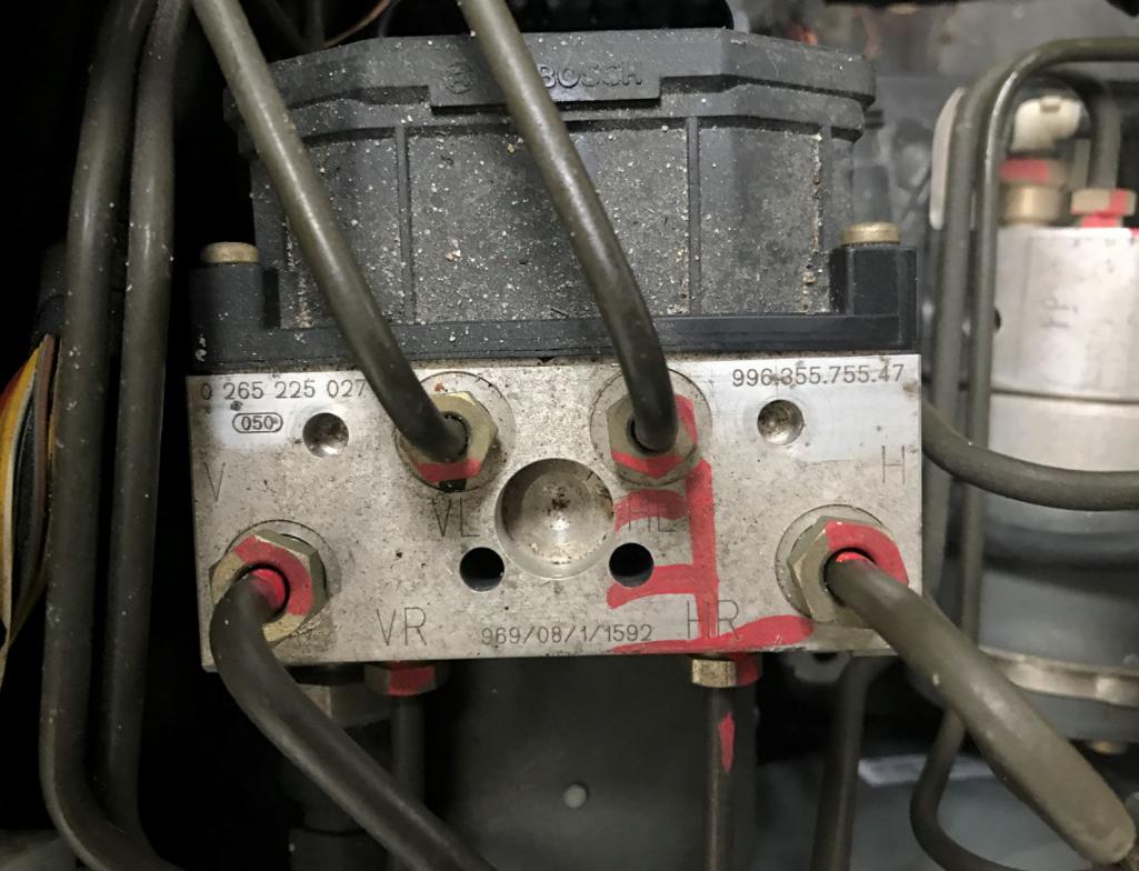
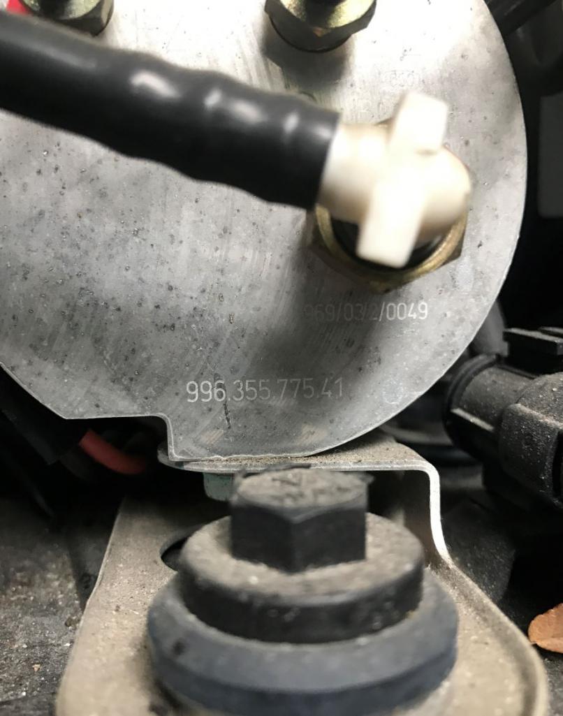
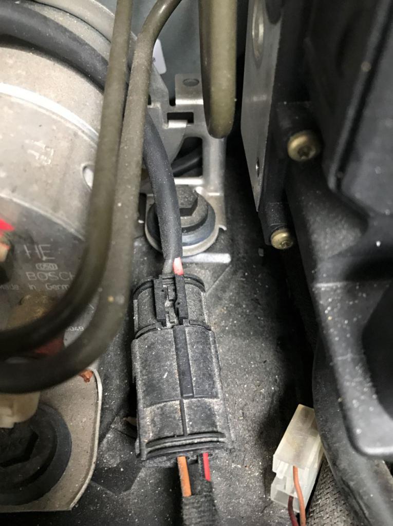
Posted by: Andyrew Feb 27 2017, 01:14 PM
That 2 pin connector is the ABS pump for the stability control system. Basically it primes the ABS box to allow for the system to hit any of the brakes at any time. Its similar to the Audi pump in design.
The first pic is the ABS box. That takes a multi pin connector, similar to the Audi. (See below)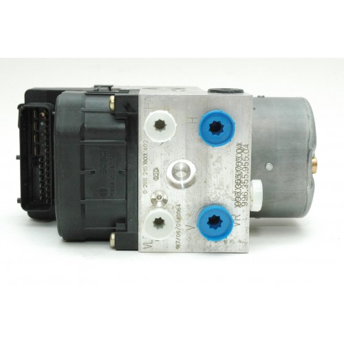
Your going to have a 10x easier time if you use the Audi stuff as your donor chassis is already wired for it.
Posted by: jd74914 Feb 27 2017, 01:15 PM
Interesting-I haven't seen one like the second one before (note that I have almost no 996 knowledge). People call it the pre-pump? Not sure exactly what it does except that it's for PSM.
The one the 951 guys use is out of early Boxsters (and maybe 996s since it does have a 996 P/N) and looks like this: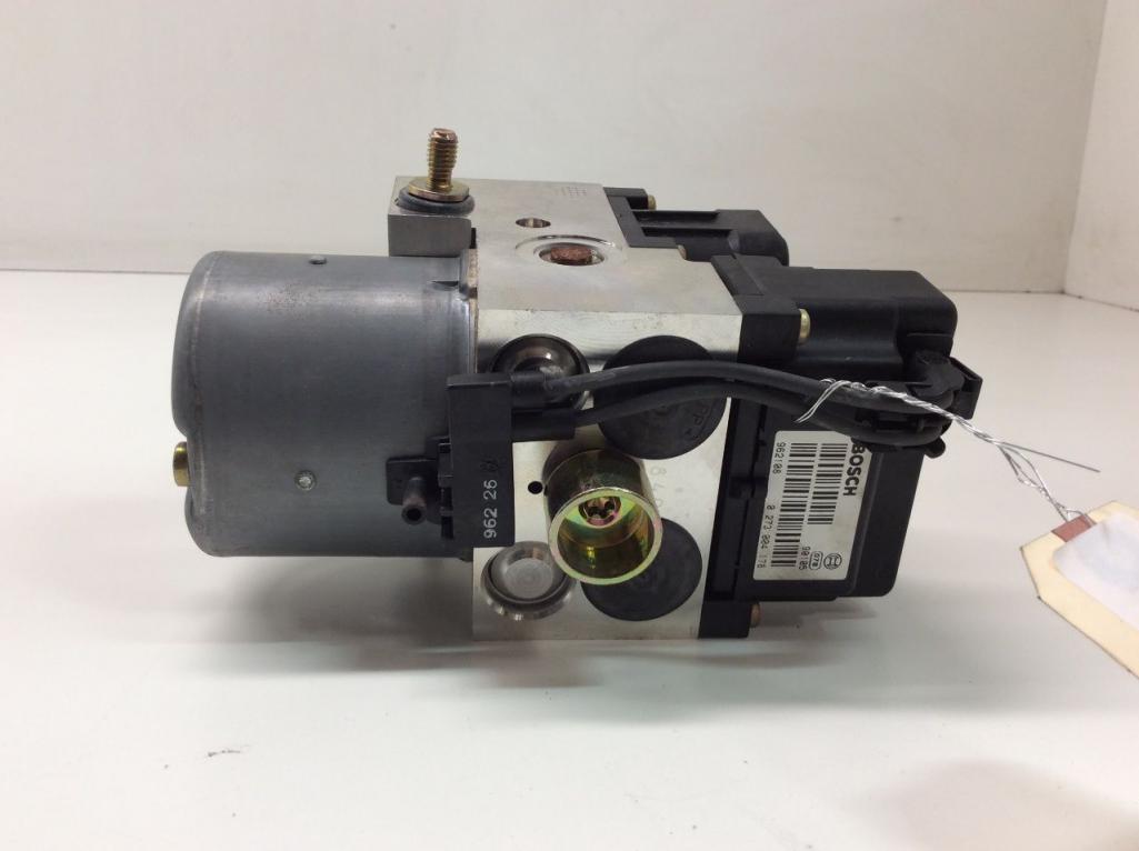
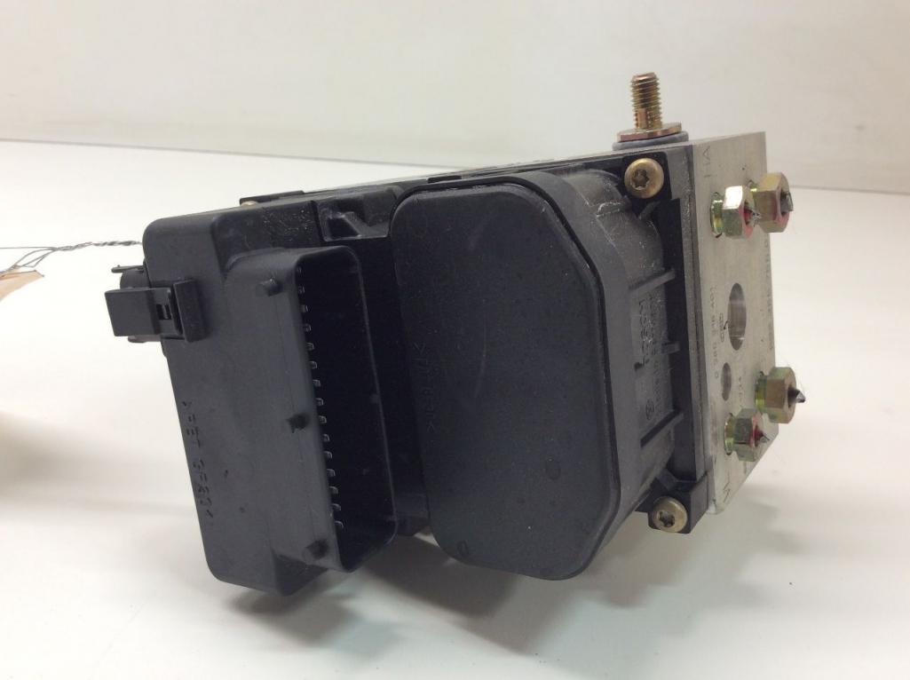
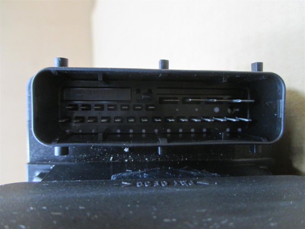
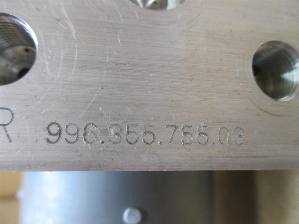
Posted by: Cracker Feb 27 2017, 01:24 PM
...and?
T
Dang T.......lotta T in that post.Posted by: jd74914 Feb 27 2017, 01:29 PM
That 2 pin connector is the ABS pump for the stability control system. Basically it primes the ABS box to allow for the system to hit any of the brakes at any time. Its similar to the Audi pump in design.
The first pic is the ABS box. That takes a multi pin connector, similar to the Audi. (See below)
Your going to have a 10x easier time if you use the Audi stuff as your donor chassis is already wired for it.
Andrew beat me!
The thing I worry about using an Audi unit vs. Boxster is that the two must have different vehicle dynamics "models" built into them. They both seem to use essentially the same hardware, but I'm sure Bosch has each programmed for the specific vehicle. I'm not sure about Audi weight distribution, but the fact that it is AWD means that there is definitely a different front axle response model which likely has some corrections for reduced lateral grip while applying power. It might work great though-the engineer in me is a little conservative.
Posted by: Andyrew Feb 27 2017, 01:49 PM
That 2 pin connector is the ABS pump for the stability control system. Basically it primes the ABS box to allow for the system to hit any of the brakes at any time. Its similar to the Audi pump in design.
The first pic is the ABS box. That takes a multi pin connector, similar to the Audi. (See below)
Your going to have a 10x easier time if you use the Audi stuff as your donor chassis is already wired for it.
Andrew beat me!
The thing I worry about using an Audi unit vs. Boxster is that the two must have different vehicle dynamics "models" built into them. They both seem to use essentially the same hardware, but I'm sure Bosch has each programmed for the specific vehicle. I'm not sure about Audi weight distribution, but the fact that it is AWD means that there is definitely a different front axle response model which likely has some corrections for reduced lateral grip while applying power. It might work great though-the engineer in me is a little conservative.
The way I see it, if race guys strip out the vehicle to weigh 1k lbs less than factory the ABS should perform the same. Stability control should perform the same.
I see the system responding to grip loss. Yes there are yaw sensors involved as well as steering angle but that will only tell the system where the car is trying to go and adjust throttle and brake in such a way to counter it.
The biggest thing that I wanted to make sure was correct for my vehicle was that I used the same size ABS teeth count for the rear as was OE for the system, so that if the system tries to read wheel speed and correct it wouldnt be dissimilar to anticipated wheel speed.
Same goes for the front of the vehicle. I run smaller overall tires in the front than the rear by a considerable margin. I would want the teeth count of the front ABS to match that ratio appropriately as the Audi runs the same size front to back.
So long as that is good, I imagine the system should be able to compensate for the weight/power balance differences.
Regarding AWD vs RWD and its limits for throttle imputs at the edge. An AWD based car has more mechanical grip on power ramp and therefore I would imagine that the base of the system would have a tendancy to oversteer on onset and then the system would bring it down when it noticed the rear wheel speed being significantly higher than the front.
Posted by: Curbandgutter Feb 27 2017, 01:52 PM
That 2 pin connector is the ABS pump for the stability control system. Basically it primes the ABS box to allow for the system to hit any of the brakes at any time. Its similar to the Audi pump in design.
The first pic is the ABS box. That takes a multi pin connector, similar to the Audi. (See below)
Your going to have a 10x easier time if you use the Audi stuff as your donor chassis is already wired for it.
Andrew beat me!
The thing I worry about using an Audi unit vs. Boxster is that the two must have different vehicle dynamics "models" built into them. They both seem to use essentially the same hardware, but I'm sure Bosch has each programmed for the specific vehicle. I'm not sure about Audi weight distribution, but the fact that it is AWD means that there is definitely a different front axle response model which likely has some corrections for reduced lateral grip while applying power. It might work great though-the engineer in me is a little conservative.
Jim, yes I was thinking about that as well. I'm not sure if they have a vehicle dynamic model built into the ecu or it's purely a comparison between wheel speeds?
Andrew, I have both systems so I'm not sure which way to go yet.
Posted by: Andyrew Feb 27 2017, 02:39 PM
https://www.dropbox.com/sh/jux2hzn05strpsf/AACMUoa0LJtoutv1AWCaVbX_a?dl=0
Some required reading on Audi ESP
Also, some wiring info for you all if you wanted to know.
https://www.dropbox.com/sh/ot2v0w9h84a1ydl/AABotkA5KsP_I1qaaSqeQ5Fma?dl=0
Posted by: Curbandgutter Feb 27 2017, 05:40 PM
https://www.dropbox.com/sh/jux2hzn05strpsf/AACMUoa0LJtoutv1AWCaVbX_a?dl=0
Some required reading on Audi ESP
Also, some wiring info for you all if you wanted to know.
https://www.dropbox.com/sh/ot2v0w9h84a1ydl/AABotkA5KsP_I1qaaSqeQ5Fma?dl=0
Wow Andrew......good stuff!! Decisions decisions. If I go with the Audi steering wheel, then it will have the turning angle unit built in, the g meter is under the seat, wow seems like it may be something to really look into. It seems that the vehicle dynamics is not built in but rather it's a real time sensor system that is continually monitoring an that will aid in the anti lock braking but will also will also brake a single wheel to help the car in over steer and under steer conditions. I'll have to really think this through.
Posted by: csdilligaf Feb 28 2017, 10:35 AM
Man you guys and your wiz bang technology. I am anti-tech. I want minimal things that don't break down or have to spend a month to sort out. But that's just me, I'm still trying to conquer posting from my Iphone.
Posted by: Amenson Feb 28 2017, 11:41 AM
https://www.dropbox.com/sh/jux2hzn05strpsf/AACMUoa0LJtoutv1AWCaVbX_a?dl=0
Some required reading on Audi ESP
Also, some wiring info for you all if you wanted to know.
https://www.dropbox.com/sh/ot2v0w9h84a1ydl/AABotkA5KsP_I1qaaSqeQ5Fma?dl=0
I work for Bosch and developed ESP for 12 years. I would strongly recommend that you not try to adapt ESP to your vehicle. Even if you were able to get a fault free system (which you won't) the control will be uncomfortable at best and likely dangerous. If you want to discuss in more detail, PM me your phone number and we can chat.
Otherwise, awesome project!
Posted by: Andyrew Feb 28 2017, 12:12 PM
https://www.dropbox.com/sh/jux2hzn05strpsf/AACMUoa0LJtoutv1AWCaVbX_a?dl=0
Some required reading on Audi ESP
Also, some wiring info for you all if you wanted to know.
https://www.dropbox.com/sh/ot2v0w9h84a1ydl/AABotkA5KsP_I1qaaSqeQ5Fma?dl=0
I work for Bosch and developed ESP for 12 years. I would strongly recommend that you not try to adapt ESP to your vehicle. Even if you were able to get a fault free system (which you won't) the control will be uncomfortable at best and likely dangerous. If you want to discuss in more detail, PM me your phone number and we can chat.
Otherwise, awesome project!
So does that mean you can help us develop slip angles and modify the bosh HEX codes?
Posted by: Amenson Feb 28 2017, 12:54 PM
https://www.dropbox.com/sh/jux2hzn05strpsf/AACMUoa0LJtoutv1AWCaVbX_a?dl=0
Some required reading on Audi ESP
Also, some wiring info for you all if you wanted to know.
https://www.dropbox.com/sh/ot2v0w9h84a1ydl/AABotkA5KsP_I1qaaSqeQ5Fma?dl=0
I work for Bosch and developed ESP for 12 years. I would strongly recommend that you not try to adapt ESP to your vehicle. Even if you were able to get a fault free system (which you won't) the control will be uncomfortable at best and likely dangerous. If you want to discuss in more detail, PM me your phone number and we can chat.
Otherwise, awesome project!
So does that mean you can help us develop slip angles and modify the bosh HEX codes?
It is a bit more complicated than you are thinking.
How about this, if you come anywhere close to describing how to accurately determine the speed of the body (in order to calculate wheel slip) while driving uphill with the wheels spinning, I will give you some offline hints on how to get ABS to work on your project.
Edit: The vehicle is AWD with open differentials.
Have fun,
Scott
Posted by: Curbandgutter Feb 28 2017, 02:06 PM
https://www.dropbox.com/sh/jux2hzn05strpsf/AACMUoa0LJtoutv1AWCaVbX_a?dl=0
Some required reading on Audi ESP
Also, some wiring info for you all if you wanted to know.
https://www.dropbox.com/sh/ot2v0w9h84a1ydl/AABotkA5KsP_I1qaaSqeQ5Fma?dl=0
I work for Bosch and developed ESP for 12 years. I would strongly recommend that you not try to adapt ESP to your vehicle. Even if you were able to get a fault free system (which you won't) the control will be uncomfortable at best and likely dangerous. If you want to discuss in more detail, PM me your phone number and we can chat.
Otherwise, awesome project!
Wow thank you got your input Amenson. Looks like I may be back to 996 3 channel abs at most. Or just screw it and go without abs. That was my original direction anyway. Thanks again.
Posted by: Andyrew Feb 28 2017, 02:59 PM
https://www.dropbox.com/sh/jux2hzn05strpsf/AACMUoa0LJtoutv1AWCaVbX_a?dl=0
Some required reading on Audi ESP
Also, some wiring info for you all if you wanted to know.
https://www.dropbox.com/sh/ot2v0w9h84a1ydl/AABotkA5KsP_I1qaaSqeQ5Fma?dl=0
I work for Bosch and developed ESP for 12 years. I would strongly recommend that you not try to adapt ESP to your vehicle. Even if you were able to get a fault free system (which you won't) the control will be uncomfortable at best and likely dangerous. If you want to discuss in more detail, PM me your phone number and we can chat.
Otherwise, awesome project!
So does that mean you can help us develop slip angles and modify the bosh HEX codes?
It is a bit more complicated than you are thinking.
How about this, if you come anywhere close to describing how to accurately determine the speed of the body (in order to calculate wheel slip) while driving uphill with the wheels spinning, I will give you some offline hints on how to get ABS to work on your project.
Edit: The vehicle is AWD with open differentials.
Have fun,
Scott
Well, this is a theoretical problem right?
ABS sensors on the wheel determine individual wheel speed. Open differentials on an AWD vehicle will have a mechanical torque based slip on the front to rear ratio, Left to right differentials will be open allowing for the wheel with the least amount of grip to spin, So if the right rear has the least amount of grip it will spin, however if the center differential has a 40/60 F/R split it will still send 40% of the power to the front allowing the vehicle to accelerate forward.
To determine body speed the wheel with the lowest wheel speed would be the most accurate in relation to road speed. Calculate the rotations of the wheel to the overall tire diameter can determine overall body speed.
Or did I misinterpret the question?
Posted by: tygaboy Feb 28 2017, 03:08 PM
Adding absolutely nothing helpful to this current set of posts, I have to say:
I am in awe of you guys who "get" all this new-fangled technologlogicalnessism.
Makes what I'm trying to do feel like working with Tinker Toys. OK, maybe an Erector Set.
Really, it's impressive what you're up to. Keep up the great work!
Posted by: jd74914 Feb 28 2017, 08:12 PM
It is a bit more complicated than you are thinking.
How about this, if you come anywhere close to describing how to accurately determine the speed of the body (in order to calculate wheel slip) while driving uphill with the wheels spinning, I will give you some offline hints on how to get ABS to work on your project.
Edit: The vehicle is AWD with open differentials.
Well, this is a theoretical problem right?
ABS sensors on the wheel determine individual wheel speed. Open differentials on an AWD vehicle will have a mechanical torque based slip on the front to rear ratio, Left to right differentials will be open allowing for the wheel with the least amount of grip to spin, So if the right rear has the least amount of grip it will spin, however if the center differential has a 40/60 F/R split it will still send 40% of the power to the front allowing the vehicle to accelerate forward.
To determine body speed the wheel with the lowest wheel speed would be the most accurate in relation to road speed. Calculate the rotations of the wheel to the overall tire diameter can determine overall body speed.
Or did I misinterpret the question?
All wheels are spinning so none correctly give vehicle speed. The one spinning slowest may be most accurate, but you don't know if it's correct enough. From my understanding in ABS terms it likely is, ESC its unlikely.
Thinking about it really quickly it would seem that you have to back it out from the measured acceleration, some simplified tire/vehicle dynamics models, and engine outputs. Perhaps it really a iterative shooting procedure since it must happen real-time? Need to give this some more thought on my end...definitely not a trivial calculation. ESC is crazy complicated.
Sorry for the hijack Rudy.
Posted by: Amenson Mar 1 2017, 12:50 PM
It is a bit more complicated than you are thinking.
How about this, if you come anywhere close to describing how to accurately determine the speed of the body (in order to calculate wheel slip) while driving uphill with the wheels spinning, I will give you some offline hints on how to get ABS to work on your project.
Edit: The vehicle is AWD with open differentials.
Well, this is a theoretical problem right?
ABS sensors on the wheel determine individual wheel speed. Open differentials on an AWD vehicle will have a mechanical torque based slip on the front to rear ratio, Left to right differentials will be open allowing for the wheel with the least amount of grip to spin, So if the right rear has the least amount of grip it will spin, however if the center differential has a 40/60 F/R split it will still send 40% of the power to the front allowing the vehicle to accelerate forward.
To determine body speed the wheel with the lowest wheel speed would be the most accurate in relation to road speed. Calculate the rotations of the wheel to the overall tire diameter can determine overall body speed.
Or did I misinterpret the question?
All wheels are spinning so none correctly give vehicle speed. The one spinning slowest may be most accurate, but you don't know if it's correct enough. From my understanding in ABS terms it likely is, ESC its unlikely.
Thinking about it really quickly it would seem that you have to back it out from the measured acceleration, some simplified tire/vehicle dynamics models, and engine outputs. Perhaps it really a iterative shooting procedure since it must happen real-time? Need to give this some more thought on my end...definitely not a trivial calculation. ESC is crazy complicated.
Sorry for the hijack Rudy.
This is not a theoretical problem. In a slip based controller accurate knowledge of the body speed is critical and a good portion of the ECU capacity is used figuring it out. Andrew did well by getting to the slowest wheel as the best indicator of body speed and jd74914 identified the issue that best probably is not good enough for ESP.
Add this to the complexity of all of the other sensors and factors that obscure the reality of what the vehicle is doing or what the driver is requesting and hopefully you will come to the conclusion that it is not a system that can be swapped between vehicles. Years of effort go into adapting the system to each production vehicle.
Once it is adapted, things like programmable drift angles are fun engineering exercises!
Cheers,
Scott
Posted by: Cracker Mar 1 2017, 01:05 PM
Scott - I'll muddy up Rudy's thread (at least) one more time...I had taken a hard look at Bosch's Motorsports ABS M4 system/kit in the past. Most people whine about the cost - anything at the pointy end of development comes at a high price. What are you thoughts regarding programming/calibrating such a system to a 914 on slicks? The appealing upside to me was the adjustable slip that can be selected based upon a number of conditions and driver preferences. Until someone else surfaces with video of locking up the front brakes on a 914 at 165 mph (not something to be proud of, just experience) - I believe I am the only one with direct experience. I see the value of such a system near the limit - just not for a hot rod, doing hot rod things.
Tony
Posted by: Amenson Mar 1 2017, 01:29 PM
Scott - I'll muddy up Rudy's thread (at least) one more time...I had taken a hard look at Bosch's Motorsports ABS M4 system/kit in the past. Most people whine about the cost - anything at the pointy end of development comes at a high price. What are you thoughts regarding programming/calibrating such a system to a 914 on slicks? The appealing upside to me was the adjustable slip that can be selected based upon a number of conditions and driver preferences. Until someone surfaces with video of locking up the front brakes on a 914 at 165 mph - I believe I am the only one with direct experience. I see the value of such a system near the limit - just not for a hot rod, doing hot rod things.
Tony
Tony
I really appreciate your consistency and dedication you have to referring to your 914 as a "hot rod"....whatever makes your insurance company happy I guess.
As for the Motorsport ABS system. I have no direct experience with it but have friends that do and happened to be stuck on an airplane with one the other week and briefly discussed some issues they found at Daytona with the NSX GT3 project they were applying the system to. From my understanding the system has basic vehicle parameters that are setup and then the base calibrations are automatically set. There are several settings that can be selected from a dial switch that are fixed and should work for most drivers. There are one or two settings that can be calibrated, probably at a huge cost. The tables might be open...I can ask if you get serious.
Contrary popular belief, very few drivers if any, can consistently out brake a car with modern ABS. People will probably make fun of you until you blow by them in the braking zone. Go for it!
Scott
Posted by: Cracker Mar 1 2017, 01:43 PM
Scott - I was referring to Rudy's car...LOL! You are correct, however, I mainly just to stick that out there to poke at Bob Saville (who happens to have a legitimate 914 race car!).
I only have a hot rod. 
Thank you for your insight regarding the M4...I cannot offer an argument against it and it would make driving at the limit a whole lot easier - to mention the added confidence it would provide! The faster one drives, using technology to ease the drivers workload becomes more and more critical. No different than the go-fast gizmo's on my prototype buggy...
T
Tony
I really appreciate your consistency and dedication you have to referring to your 914 as a "hot rod"....whatever makes your insurance company happy I guess.
Scott
Posted by: Curbandgutter Mar 1 2017, 02:18 PM
So after this round of A....BS talk it looks like the Audi ESP is out of the picture. I'll still take a hard look at the ABS of off a boxster.
Posted by: Cracker Mar 1 2017, 03:05 PM
Hey. I didn't start this stuff...I helped put a stop to it!
T
So after this round of A....BS talk it looks like the Audi ESP is out of the picture. I'll still take a hard look at the ABS of off a boxster.
Posted by: Curbandgutter Mar 3 2017, 07:23 PM
Well motor is out of the Audi. It was amazing how these things are packaged. True nightmare to work on in the Audi but won't be a problem in the 914. Heck I'll be able to walk into the engine compartment. Great motor, but the way it is shoved into the Audi, it sucks big time. You forget how short these Audi V6's are. It measures about 18 inches long. So it's about 6" shorter than an LS1 or Coyote. Makes sense since its 2 cylinders short.
Posted by: tygaboy Mar 3 2017, 08:58 PM
Well motor is out of the Audi. It was amazing how these things are packaged. True nightmare to work on in the Audi but won't be a problem in the 914. Heck I'll be able to walk into the engine compartment. Great motor, but the way it is shoved into the Audi, it sucks big time. You forget how short these Audi V6's are. It measures about 18 inches long. So it's about 6" shorter than an LS1 or Coyote. Makes sense since its 2 cylinders short.
I see... So in my build, short is bad but in yours, it's good.
Glad to hear it's coming together for you, Rudy!
Posted by: Curbandgutter Mar 5 2017, 12:02 PM
^^^ Well I separated the Audi motor from the triptronic and weighed it with , alternator, power steering pump, air conditioner, Ac drier, full of oil, headers, turbo , electric harness and torque converter. It weighed......a little shy of 440 lbs. I wonder how much a wet and fully dressed LS motor weights. I need to compare apples to apples though. Therefore the LS motor must have flywheel, clutch, exhaust headers, all peripherals, electronics, fuel injection, and intake system. Has anyone weighed this or have good information on this??
Posted by: csdilligaf Mar 5 2017, 02:18 PM
So today's project was to get a drill fixture made so Rudy can have more bolts to hold the engine and trans together. I took the adapter plate and put it on my CMM to measure hole locations. Made the drill fixture with two locating pins in the alignment holes and four long drill bushings for the lower four holes that line up on the engine along with two hold down bolt holes. The Cayman S 6 speed has solid bosses at the correct location but Porsche does not drill them since the Cayman motor does not need them. Its nice that they are there though. Now we can use all of the bolt holes in the engine. I think it will be best to drill and tap the trans and then use short studs as needed. One of the holes is bolt that holds the starter in place and sliding it on a stud will help.
Attached thumbnail(s)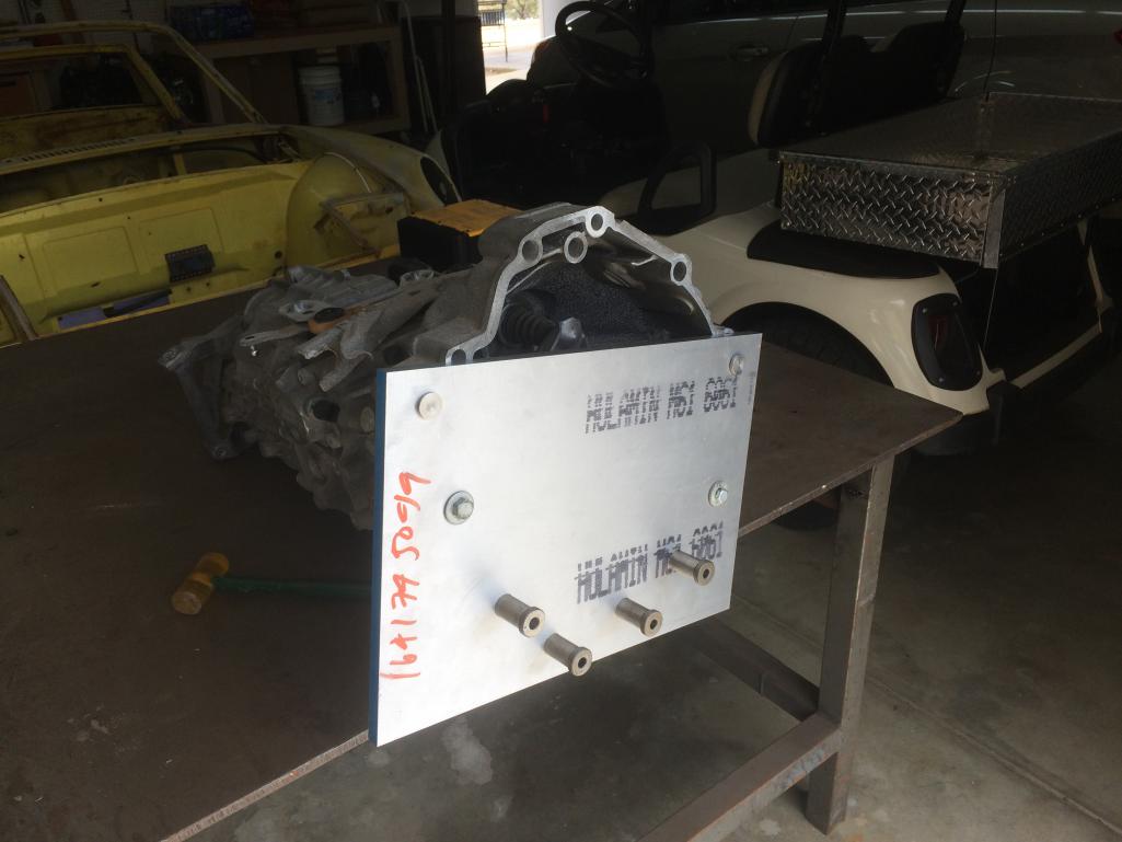
Posted by: Andyrew Mar 5 2017, 05:24 PM
^^^
Well I separated the Audi motor from the triptronic and weighed it with , alternator, power steering pump, air conditioner, Ac drier, full of oil, headers, turbo , electric harness and torque converter. It weighed......a little shy of 440 lbs. I wonder how much a wet and fully dressed LS motor weights. I need to compare apples to apples though. Therefore the LS motor must have flywheel, clutch, exhaust headers, all peripherals, electronics, fuel injection, and intake system. Has anyone weighed this or have good information on this??440 is spot on for the 2.7
By comparison the 1.8 is 282 with all the accessories. Mine doesnt have the power steering pump, ac compressor, some emissions bits, and a bunch of bracketry so knock off 30lbs and my engine is right around 250.
One of the big reasons I went this route vs the V6 motor. (Granted my cast aluminum intercooler is about 30lbs, my turbo is about 10, and my engine cradle is another 10...)
An aluminum LS1 is about 430
Posted by: Cracker Mar 5 2017, 08:15 PM
The flywheel, clutch, PP and adapter plate for the LS to G86/87 variants is substantial, heavy (and pretty). I didn't weigh it but would guess that it alone weighs about 55 lbs. Chris could weight his since his is still accessible. My engine only has an alternator and dry sump pump and weighs 425 lbs. A baseline comparison for power goals to engine weight - 586 hp and 553 torque - at the crank. Idles smooth, and can drive at idle with no throttle input. Very docile.
T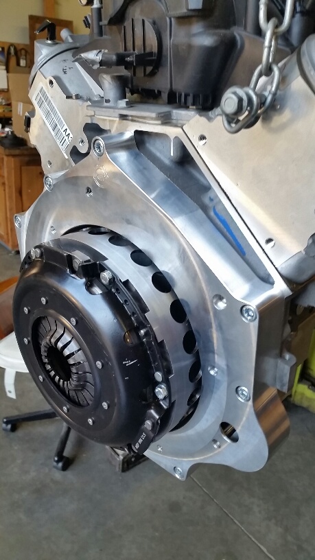
Posted by: Curbandgutter Mar 5 2017, 10:34 PM
Thanks T. that LS7 is legendary. The little V6 can't compete with that monster. Chris if you get a chance can you weigh your LS3 fully dressed. Please include headers and clutch with adapter plate if possible. I've checked other sites and they say that GM's official fully dressed weight is 497 lbs but it doesn't include clutch and adapter kit or headers. Therefore, if I read T right then, I suspect that a fully dressed LS motor will weigh around 497 + 50(clutch and adapter) + 20 (headers).= 567 lbs. Does that sound about right?
Posted by: Curbandgutter Mar 6 2017, 01:29 PM
I went down South to Chip's house and he tapped in four additional studs to the Cayman transmission. You can see them in the first picture (Chip's motor and trans). He machined up a trick jig and was able to set it up and tap the trans in about five minutes. For those of you that may want to do this, these studs are not mandatory but we like our belts and suspenders around here.
Attached thumbnail(s)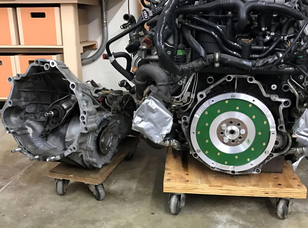
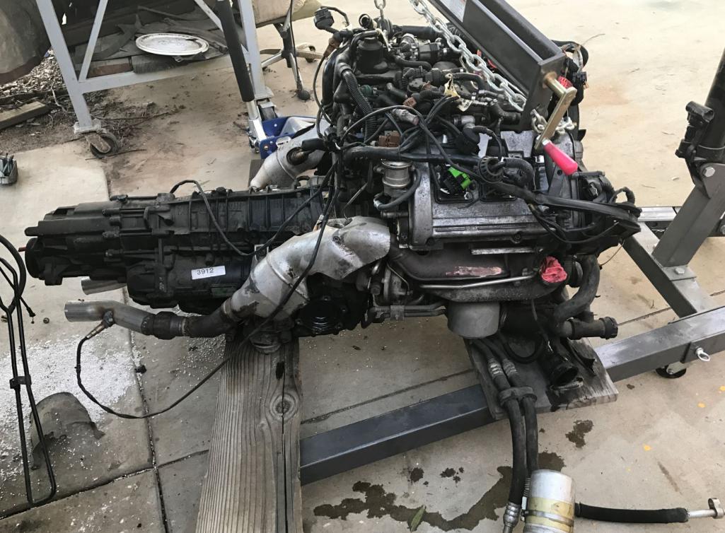
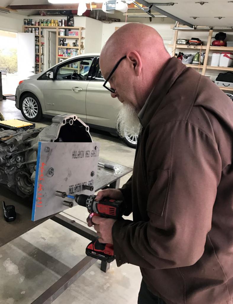
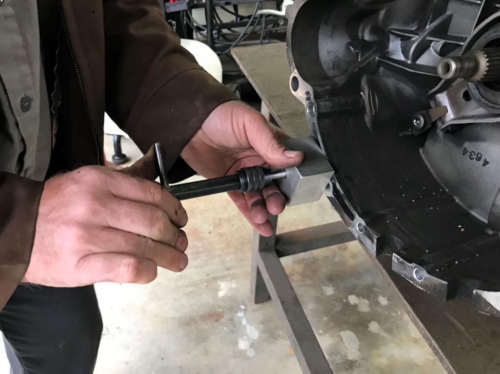
Posted by: Mueller Mar 6 2017, 02:50 PM
^^^
Well I separated the Audi motor from the triptronic and weighed it with , alternator, power steering pump, air conditioner, Ac drier, full of oil, headers, turbo , electric harness and torque converter. It weighed......a little shy of 440 lbs. I wonder how much a wet and fully dressed LS motor weights. I need to compare apples to apples though. Therefore the LS motor must have flywheel, clutch, exhaust headers, all peripherals, electronics, fuel injection, and intake system. Has anyone weighed this or have good information on this??440 is spot on for the 2.7
By comparison the 1.8 is 282 with all the accessories. Mine doesnt have the power steering pump, ac compressor, some emissions bits, and a bunch of bracketry so knock off 30lbs and my engine is right around 250.
One of the big reasons I went this route vs the V6 motor. (Granted my cast aluminum intercooler is about 30lbs, my turbo is about 10, and my engine cradle is another 10...)
An aluminum LS1 is about 430
Great to see these numbers posted, too bad the 1.8 or the V6 models available with aluminum blocks. I think the Type IV is right at 300 pounds complete?
Posted by: csdilligaf Mar 6 2017, 06:56 PM
So my wife meets Rudy when he was here and when he leaves she asks "did you guys work on the Paudi" as in Pow-Dee. She thinks she's pretty funny
Posted by: Curbandgutter Mar 7 2017, 10:52 AM
That should be your license plate
Posted by: Mueller Mar 7 2017, 01:44 PM
I went down South to Chip's house and he tapped in four additional studs to the Cayman transmission. You can see them in the first picture (Chip's motor and trans). He machined up a trick jig and was able to set it up and tap the trans in about five minutes. For those of you that may want to do this, these studs are not mandatory but we like our belts and suspenders around here.
Nice fixture, great to see you using the tapping block!
Posted by: Curbandgutter Mar 13 2017, 12:26 PM
OK this weekend I mated the Cayman Trans with the Audi motor. I started removing all of the excess piping and tubing that are unnecessary . It really started to clean that rats nest of tubing up quite a bit. I'll post pictures when done. Hoping to place motor in this weekend and then make the motor mounts. Chip will then start mocking up for the custom headers. I'd like to have the motor completely bolted up this month since I will not be able to work on the work for the first two weeks of April.
My remaining schedule should look like this:
April: Complete the new floor pan and button up all of the access holes.
May: Complete radiators with AC system.
June: Complete brakes, and fuel system.
July: Complete electrical system and start the car.
August: Complete body with steel gt flares
September: Complete custom body work
October: Paint
November: Interior.
We will see how it pans out but this is the schedule until reality hits hard.
Attached thumbnail(s)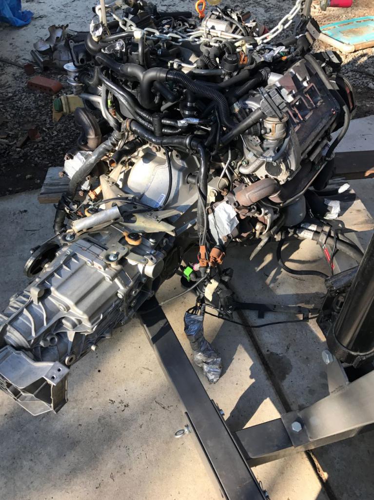
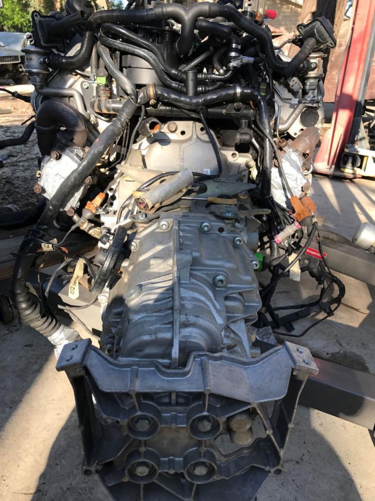
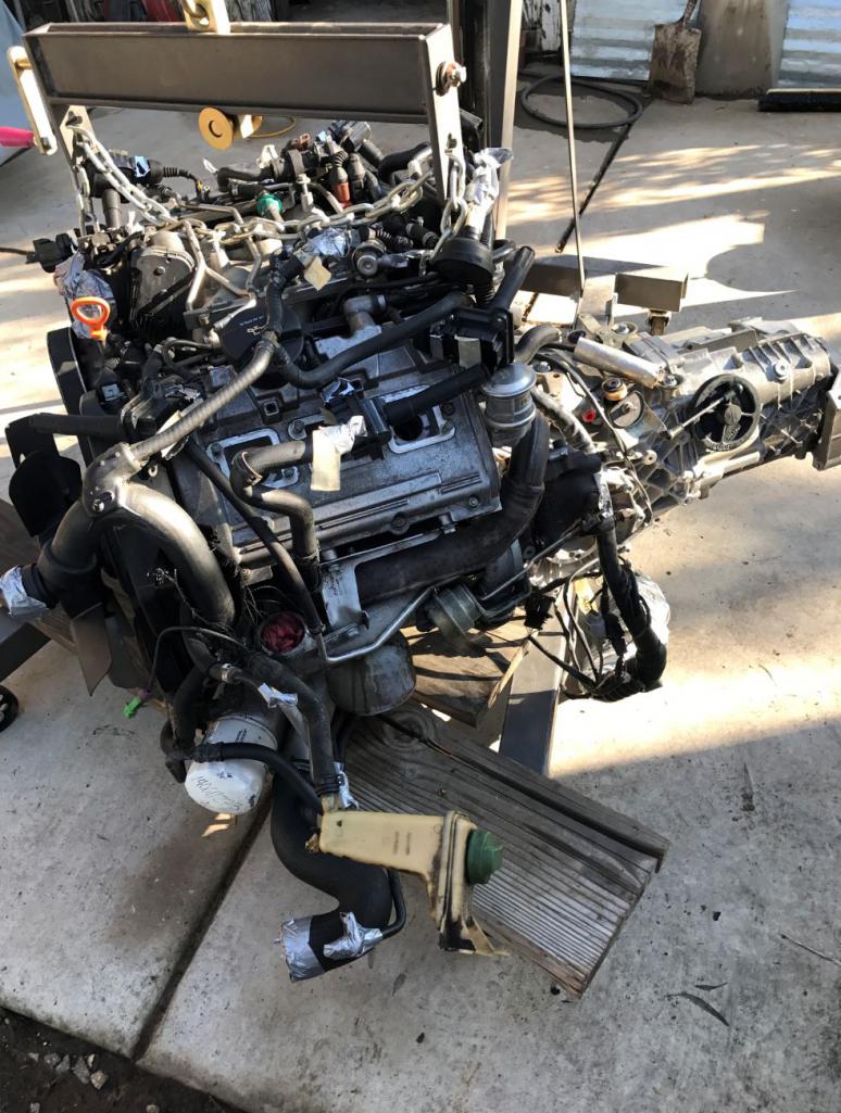
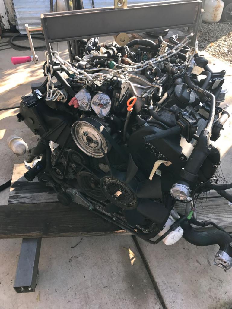
Posted by: Mueller Mar 13 2017, 12:51 PM
That is one ugly @ss motor with all those hoses, wires and such, should look decent cleaned up!
Posted by: Curbandgutter Mar 13 2017, 01:14 PM
I'll post a before and after picture. I'm removing the activated charcoal, the pcv and the secondary air pump. Ill build a puke tank for the PCV. Andrew whats been your experience on this?
Posted by: Andyrew Mar 13 2017, 01:49 PM
SAI is emissions only and can be removed no issues.
Removing the charcoal/pcv isnt an issue you just have to have a place for the air to go, Puke tank works well, I have mine puking to atmosphere and it makes quite a mess. 034 motorsports makes a 1" billet adapter to the charcoal tank so you can route your puke system from there.
Another thing you have (2.7 vs 1.8) that I dont, is under the intake manifold you have a small bosch water pump with hoses that pumps water through the turbos / engine after engine shut off. Its common to remove that system as the hoses crack or the pumps leak.
Now my water pump ECU does something similar to that, but Im not sure if you want to retain that feature. Its something the ECU controls if the oil temp gets to a certain point.
I would start discussing all this with your tuner now. What do they need, What can you remove. Thats what I did, and they guided me to where I was.
Ask them about fueling, injectors, pressure regulator, Map sensor, MAF sensor, Boost control. Those are all things that need a serious discussion before parts bought.
Posted by: 76-914 Mar 13 2017, 07:31 PM
Rudy, hábla me cuando empiezas el Aire Condicionado. Tengo la herramienta prensado de manguera barrera. Kent
Posted by: Curbandgutter Mar 13 2017, 11:39 PM
Rudy, hábla me cuando empiezas el Aire Condicionado. Tengo la herramienta prensado de manguera barrera. Kent
Damn Kent that was actually pretty good Spanish. I was busting up imagining you saying that, with that crazy side grin. Thank you, I will take you up on that.And now for the non Spanish speakers, he said,
"Rudy I like to wear leopard leotards and high heels as I drive my 914" verbatim I swear
Posted by: Curbandgutter Mar 15 2017, 09:14 PM
Andrew thanks for your response. I'm interested in how your electric pump also doubles as a secondary pump for when the engine shuts off. I'm actually still thinking of using the Audi belt driven pump for primary and the Bosch pump as it was meant to be in its original state.
Posted by: Andyrew Mar 16 2017, 08:28 AM
My electric pump has its own controller that when the key is off and the engine is hot will run the pump and fans for a couple minutes. I can program the temp at which the system trys to stay at from 140-205deg. 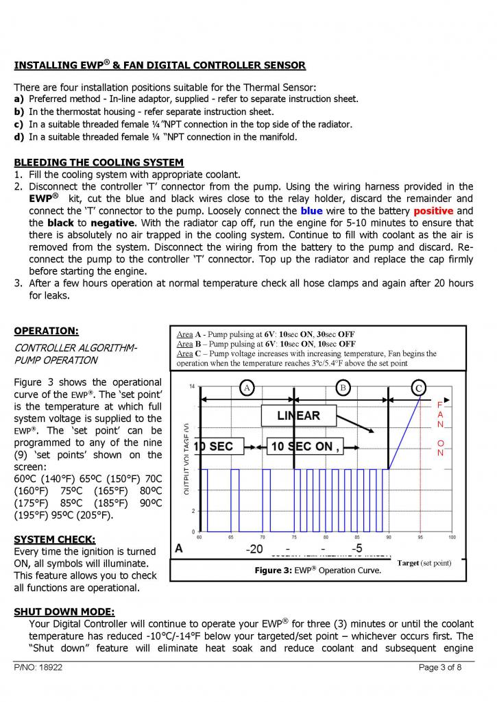
Posted by: 76-914 Mar 16 2017, 10:51 AM
Rudy, hábla me cuando empiezas el Aire Condicionado. Tengo la herramienta prensado de manguera barrera. Kent
Damn Kent that was actually pretty good Spanish. I was busting up imagining you saying that, with that crazy side grin. Thank you, I will take you up on that.And now for the non Spanish speakers, he said,
"Rudy I like to wear leopard leotards and high heels as I drive my 914" verbatim I swear
What can I say. It's not my first language. I meant to say Black not Leopard.
Posted by: bernbomb914 Mar 16 2017, 12:52 PM
Rudy can you give me the phone#of the fellow in menefee that you mentioned who knows fuel injection systems and has a shop thanks Bernie
Posted by: Curbandgutter Mar 16 2017, 04:36 PM
Rudy can you give me the phone#of the fellow in menefee that you mentioned who knows fuel injection systems and has a shop thanks Bernie
Bernie, he is no longer in California. He move to Lake Havasu. His name is Ben Strader and he owns a company called EFI university. https://www.efi101.com/ Take his classes and learn how to fix it yourself. He is an incredible instructor and explains everything in a very logical and progressive manner. It may be immensely fun for you.
Posted by: Curbandgutter Mar 18 2017, 03:56 PM
Well I we were able to place the motor to check for clearance and glad to say that it was a success. I'll have to adjust one tube to clear an oil filter but everything else fit great. Next step is to order some Z06 motor mounts and tie the motor in place.
Attached thumbnail(s)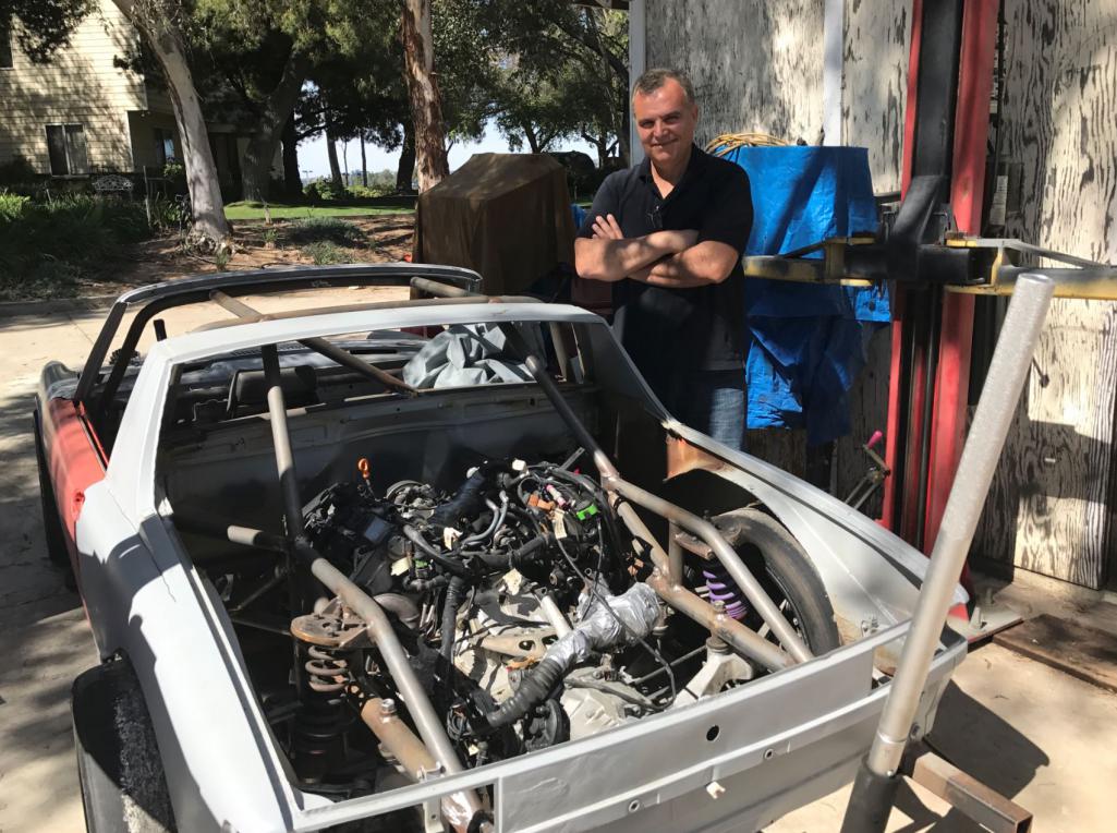
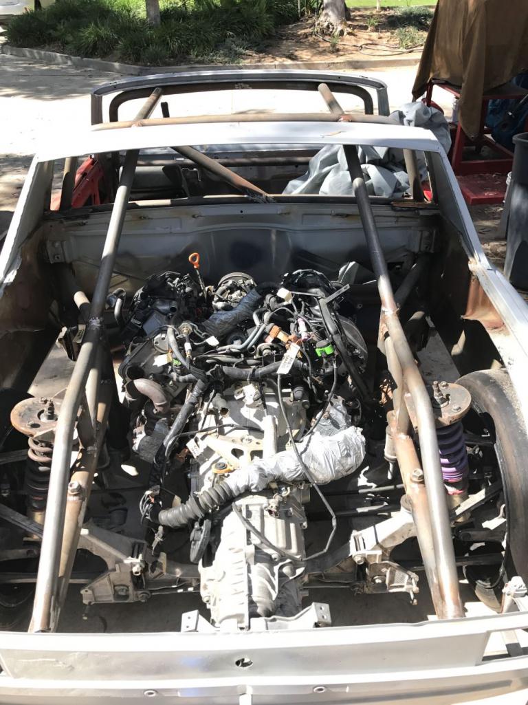
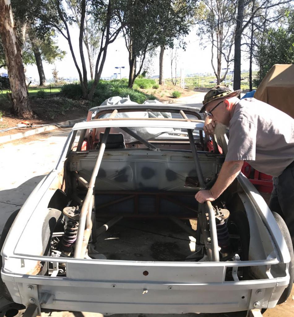
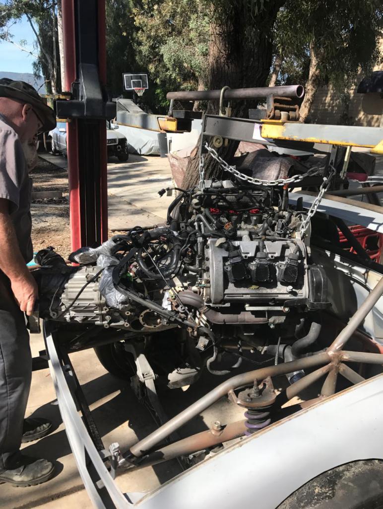
Posted by: tygaboy Mar 18 2017, 05:51 PM
I know I'm not the first to say this, but:
THAT... is a lot of wires!
Here's to success as you get to hookin' up all that!
And Triple Super Bonus Points for being the only 914 (I've ever seen) where the motor/trans goes in from the top!
Posted by: Andyrew Mar 19 2017, 07:42 AM
Whats crazier is that that white taped up lump I am going to say is the rest of the engine harness wiring
The biggest issue facing conversion owners is the wiring goes the wrong way, requiring us to extend the factory wiring or cut and rewire most of the engine components.
It not THAT big of a deal because most of the engine bay stuff gets resistors on it and is not used. My local tuner is building wire tuck wire harnesses for the 1.8's, I might pick one up and rewire my engine bay because I have a big loop of wires that are just unnecessary.
Posted by: csdilligaf Mar 19 2017, 08:23 AM
I can machine and fabricate any thing but when it comes to wiring about all I know is red wire + black wire -. When I look at the bundle of harness I am intimidated for sure. Rudy seems to have a grasp on it and I ran across an Audi mechanic that loves the 2.7 and will help out as needed. Keeping fingers crossed.
Posted by: Cracker Mar 19 2017, 08:35 AM
Probably one of the most critical areas of emphasis in race cars are the electronics. Nothing matters much about a build if it is plagued by electrical gremlins (which can lead to: failures, fires, blah, blah, blah). The difference between the quality of electrical components and emphasis on such is often under-valued...or misunderstood. In a complex car like Rudy's...I believe nothing should get more attention than the electrical system, nothing. Good luck Rudy...
Tony
Posted by: Curbandgutter Mar 19 2017, 10:42 AM
Tony I agree 100% the devil is going to be in the wiring with all of the sensors and actuators. Also need to make sure that there are no boost leaks. I plan on taking all the time necessary to get the wiring done right. Will lay out the entire system on a huge table and check every wire and connection. I have a close friend who is an electrical engineer and has written multiple university textbooks. Guy can make his own chips.....as in designing the circuit and actually building the chip in his garage. I think with him and the knowledgeable folks in this board I'm going to be all right.
Andrew yes that big lump is the wiring harness. I wrapped it in cellophane. I'll sure be needing your's and Mike Bellis' input when I get into it.
By the way, I'm checking out for a while on vacation.
TTYL
Posted by: Andyrew Mar 19 2017, 11:39 AM
I can machine and fabricate any thing but when it comes to wiring about all I know is red wire + black wire -. When I look at the bundle of harness I am intimidated for sure. Rudy seems to have a grasp on it and I ran across an Audi mechanic that loves the 2.7 and will help out as needed. Keeping fingers crossed.
Black wire is not ground in german cars
Solid brown is.
Posted by: csdilligaf Mar 19 2017, 02:48 PM
Hell, I hardly ever get passed the red/black on the battery but that does explain why most everything I try to wire smokes.
Edit:
Now I am curious since I have never had a 914 that did not start as a gutted shell with out any wiring at all is the battery ground brown as well?
Posted by: Curbandgutter Mar 23 2017, 09:46 PM
Well look what came in the mail today!
Attached thumbnail(s)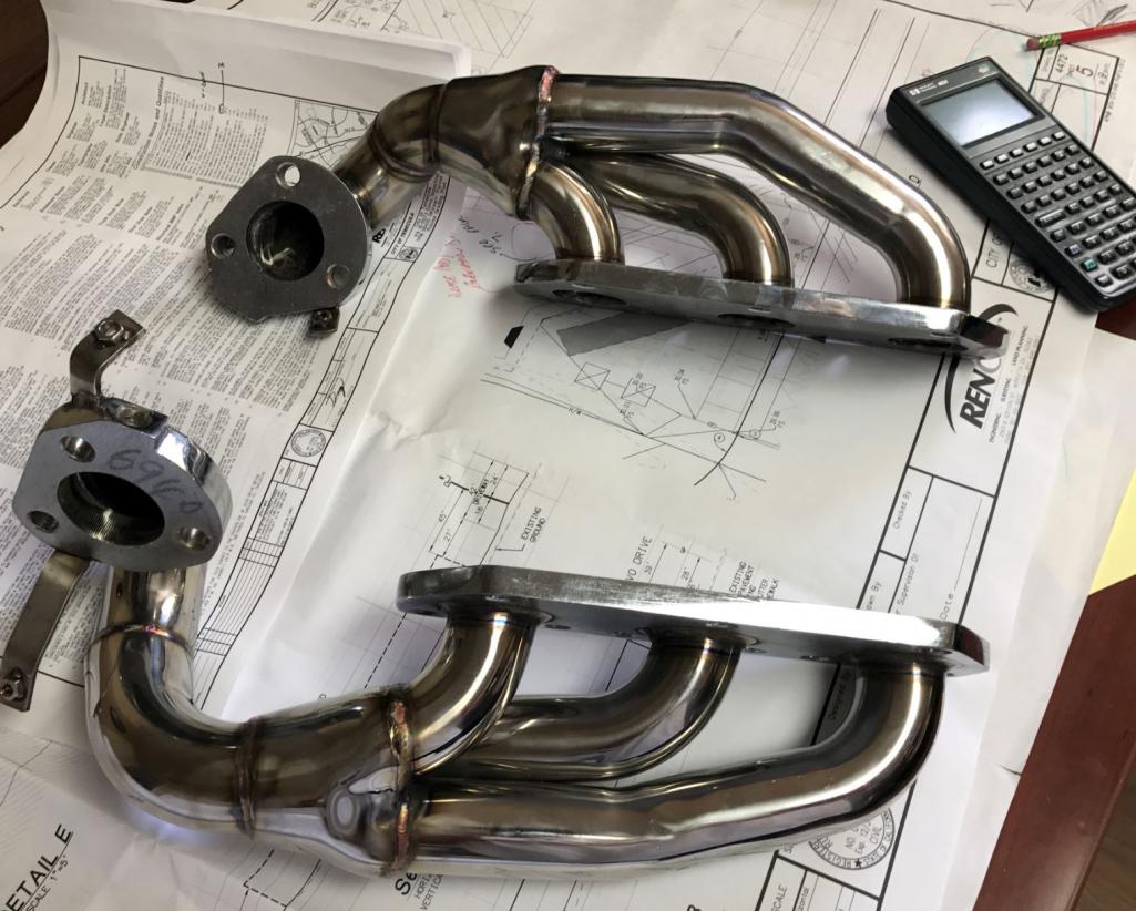
Posted by: falcor75 Mar 24 2017, 02:20 AM
Whooo, Snailbrackets
Posted by: Dion Mar 24 2017, 04:03 AM
Wow Rudy! That's a lot of work.
Have to agree about wiring issues. I witnessed Dave
(914dave) dealing with his harness and the 3.2. So many roadblocks with power not
going where it's supposed to.
All sorted though.
Rudy, looking fantastic. Nice progress. Carry on...
Cheers, Dion
Posted by: Andyrew Mar 24 2017, 07:54 AM
Well look what came in the mail today!
Those look like Chinese headers.
Please tell me there notYou have a number of solid options, most go OEM but here is a list in no order..
1. OEM
2. Ported OEM
3. AWE $3k headers.
4. $1750 Wagner headers
5. $900 Custom built like Silly Rabbit Motorsports, Built from thick stock material.
Those OBX/XS/$150special headers crack. They simply cant stand the heat that the turbos produce, especially with the boost turned up.
AWE
https://www.3zero3motorsports.com/store/a-w-e-tuning-audi-2-7t-rs4-tubular-exhaust-manifolds
Wagner
http://www.andysautosport.com/products/wagner__150001009.html
My money would go with silly rabbit motorsports I've got a link to their flow charts as well below.
http://sillyrabbitmotorsport.com/b5-s4-exhaust/audi-s4-exhaust-manifolds
http://www.myaudis4.com/srm-exhaust-manifold-flow-test/
Unrelated Note on my setup I am running an APR Iconel manifold for a 1.8T, if there is one thing in my engine build that will never break, its that manifold.
Posted by: csdilligaf Mar 24 2017, 03:42 PM
Rudy and I discussed the header plan. At first I was going too make us both a set and go equal length and relocate the turbo's to a better location for our needs but then in the interest of speeding up the process we decided to go cheap to get it running. We were aware of the cracking issue but Hell, at $135 they are disposable. We will most likely chop and modify them at least once. So consider them mock up.
Posted by: Mike Bellis Mar 24 2017, 04:43 PM
I went through a similar issue with my 1.8T. I bought several headers/manifolds trying to find the right location for my turbo. I had a nice SS equal length header that I cut up trying to realign the turbo housing to no avail. A $79 ebay special ended up being perfect. I still have about $1,200 in exhaust manifolds collecting dust in my garage...
Posted by: csdilligaf Mar 24 2017, 06:11 PM
cheapy's will work for testing but a little more money and these ones made from 1 1/4" schedule 10 stainless pipe would be better when time to finalize things. For what they cost I can't buy the flanges, elbows and pipe and then weld them up.
http://www.ebay.com/itm/3mm-thick-MANIFOLD-HEADER-EXHAUST-1997-02-AUDI-S4-B5-A6-C5-QUATTRO-2-7L-BI-TURB-/122006739130?hash=item1c682b18ba:g:c0EAAOSwLnBXUXL0&vxp=mtr
Ideally I want to delete the pig tail curl they have and lower the turbo with the outlet angled up slightly to clear the axels. We'll see if that is what works on Rudy's first.
Edit: They are XSPower. With some research on XSPower turbo headers I found
"XS Power is proud to be partnering with Stainless Works"
"Stainless Works manufactures them on-site, right here in the United States"
Posted by: csdilligaf Mar 25 2017, 08:06 AM
OK Rudy's lets see if with all the emission and things we don't need if you can get rats nest of wires to look like this?
Attached image(s)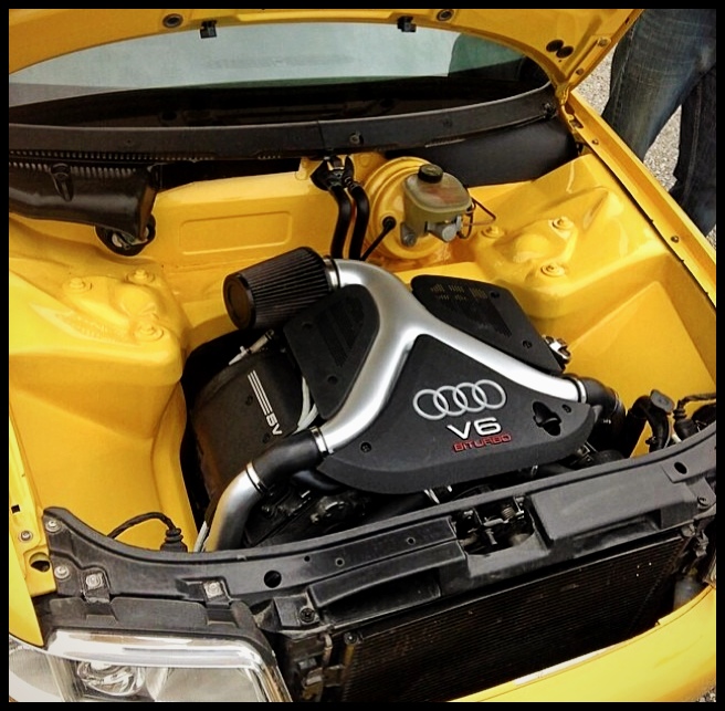
Posted by: Curbandgutter Mar 25 2017, 08:51 AM
Hahahaha. Seems to me like that car does not run. We're getting rid of the evap, the secondary air and pcv. It cleans up quite a bit. Getting it to look like that may be difficult. We will come close though. The problem that we have is that al of the wiring is along the firewall of the Audi which can hid the wiring. In our case all of our wiring is visible since it's mid engine. We will have to come up with some fancy way of hiding the wiring.
Posted by: Andyrew Mar 25 2017, 09:18 AM
For me the biggest thing was there was so much stuff to fit in the engine compartment something like this was no way a possibility. I mean the piping for the intercooler take up a considerable amount of room and you'll have two turbos to pipe to either one A/W IC or run twin side mounts.
Posted by: Curbandgutter Mar 25 2017, 12:09 PM
I agree Andrew the piping for the intercoolers will take up space. However, I have the luxury of not having a rear trunk and rear firewall. Therefore, since I am going to create a side vent into the engine compartment at each quarter panel, I will be able to fit the intercooler in such a way as to simplify the plumbing. The side vents will fold into the quarter panel rather than protrude like a scoop. They will follow the angle of the tube chassis as it tapers from the B pillar rollbar to the where it pinches at the rear suspension. I'm toying with the idea of making the vent, as it folds in, out of carbon fiber. I set the intercooler in place and it fits perfectly. The intercoolers wil be set in such a way that when the rear hood and rear fenders tilt back, the intercoolers will be exposed. See attached for a preview.
Attached thumbnail(s)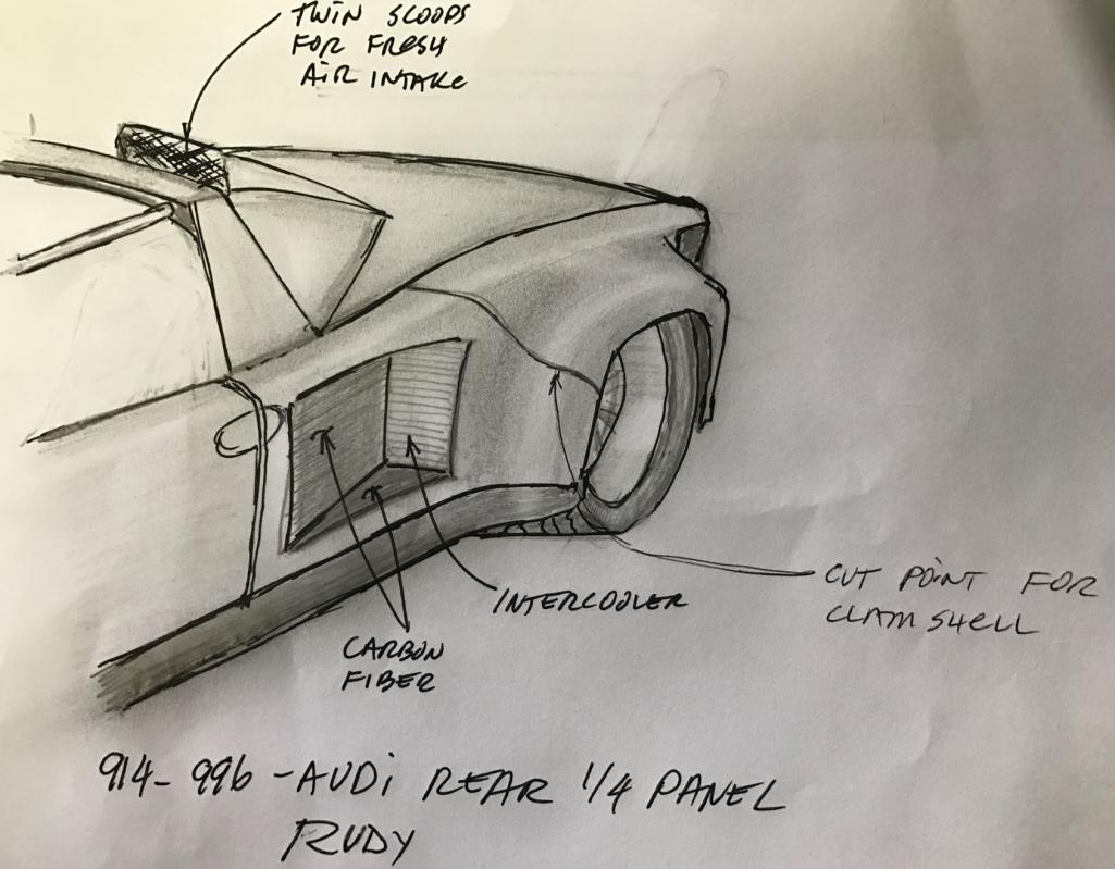
Posted by: Curbandgutter May 9 2017, 02:36 PM
Wow it's been a while. Was out on vaca and had to dig out of a ton of work. Back on the project now. Had to make a lifting cradle since I need to lift the engine out of the car often. This contraption worked out perfectly. The next step is to fab the engine supports and finish the last chevron brace in the rear. I'm ordering a new floor pan since that is the next order of business once the engine is tied into the frame.
Attached thumbnail(s)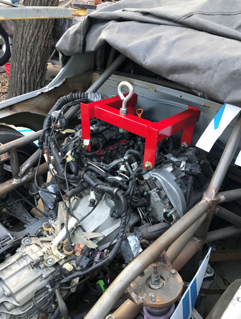
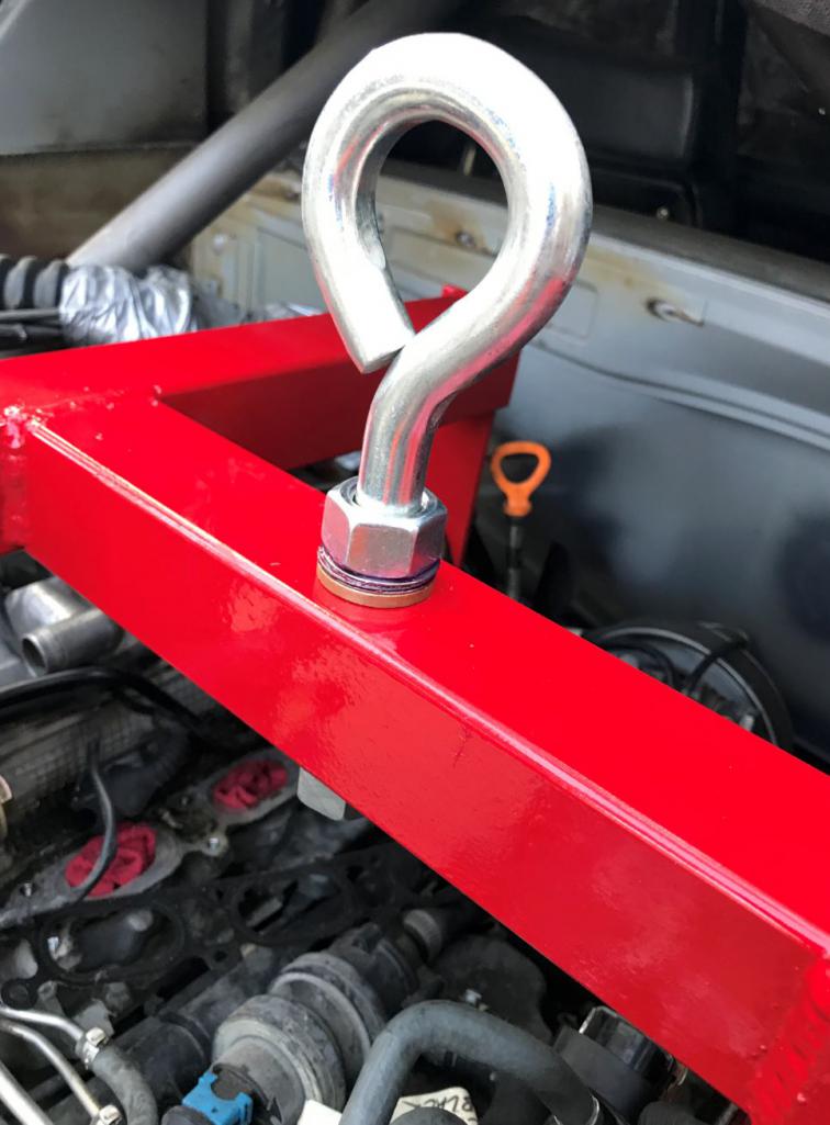
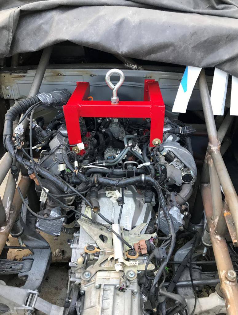
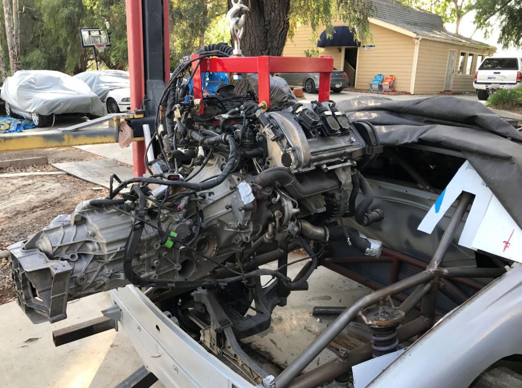
Posted by: tygaboy May 9 2017, 02:53 PM
Rudy - Good to see you back at it.
I'm still weeks away from working on mine...
Posted by: Curbandgutter May 11 2017, 07:15 AM
It's nice to be back. Hope you get better soon and are able to get your project going again. The time off has been good to get the creative juices flowing again.
Posted by: Curbandgutter May 13 2017, 12:49 PM
Well I got the car back on the chassis table to level everything up and place engine where it needs to be. I like its final position. The oil pan is 1/2" above the floor and the engine sits almost level. The engine and transaxle are shoved forward as much as possible. This will give me a more balanced car in conjunction with extending the wheelbase 3". The next step is to weld the engine mount s. After that it will be floor pan and finish buttoning up all of the welds and covering up all access holes.
Attached thumbnail(s)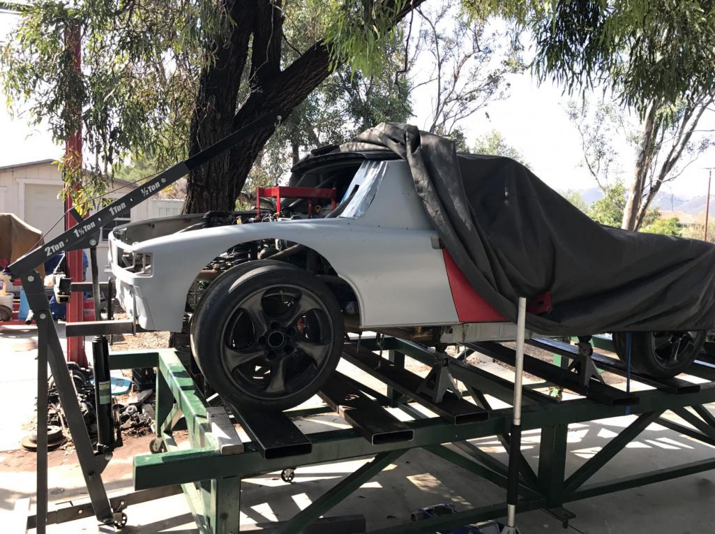
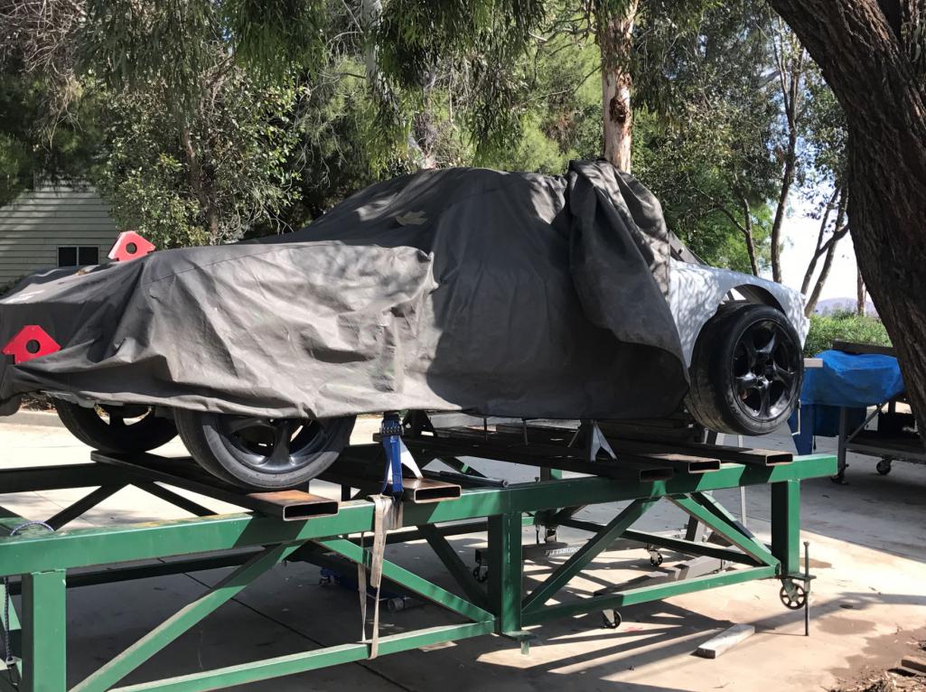
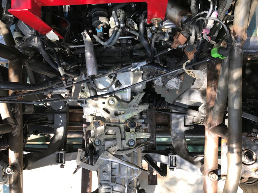
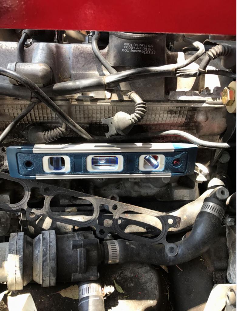
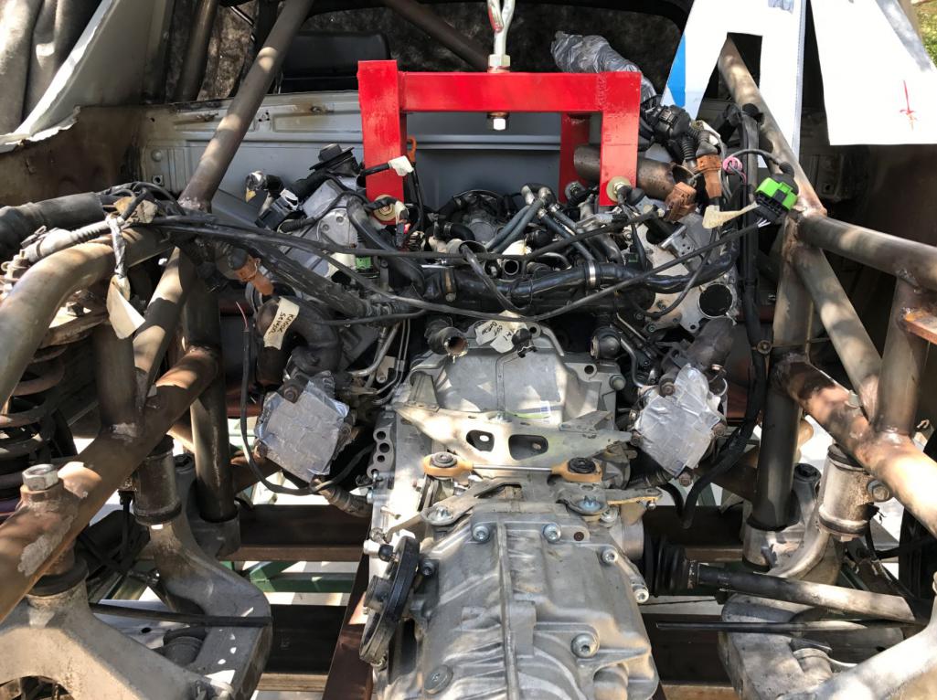
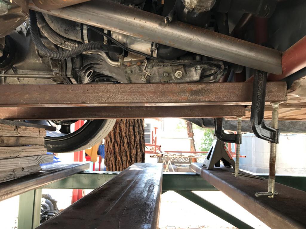
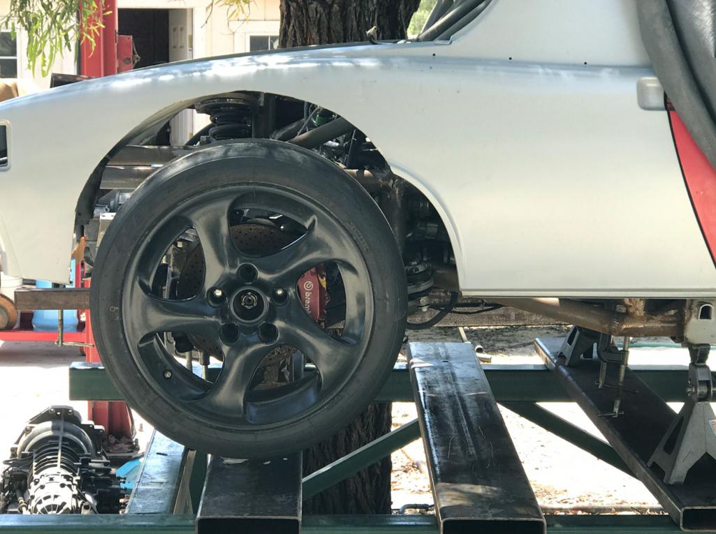
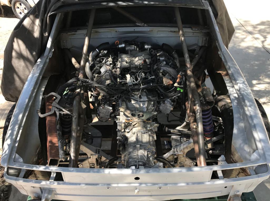
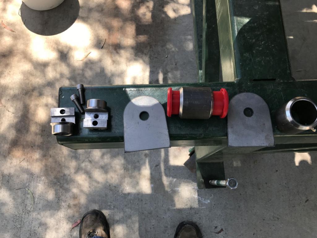
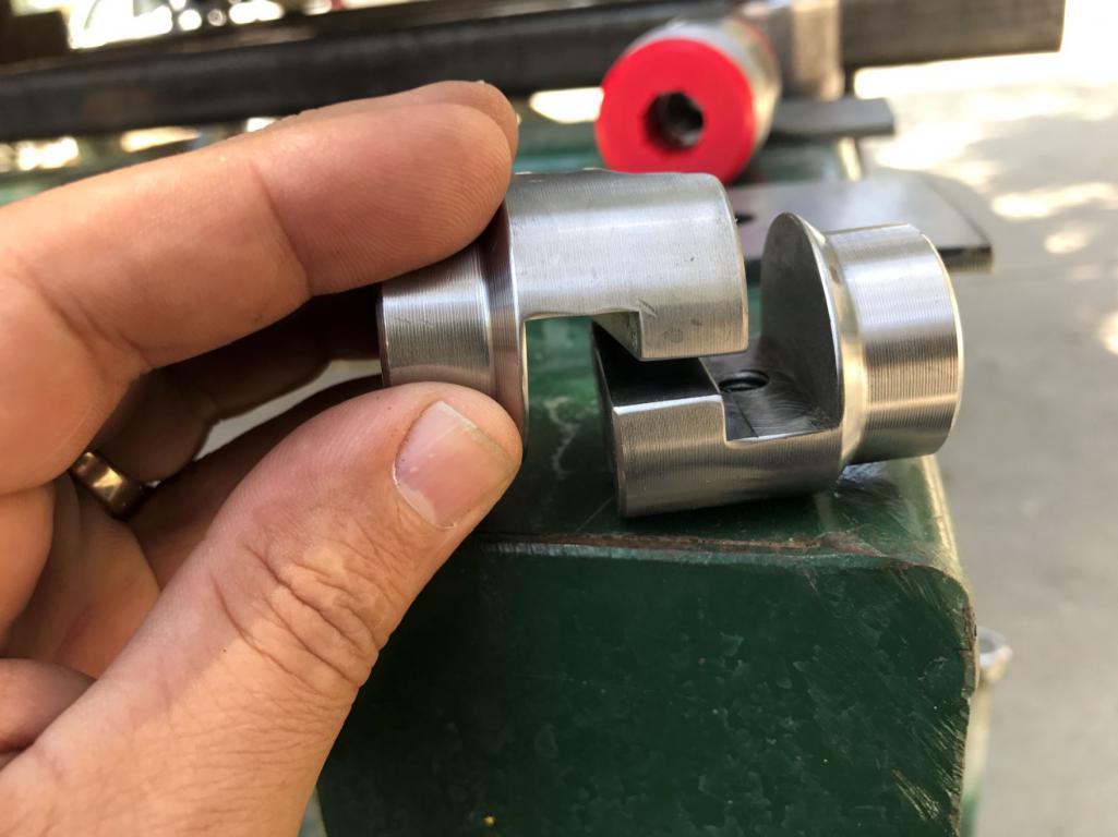
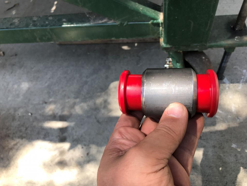
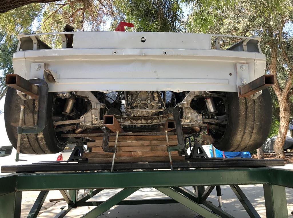
Posted by: Andyrew May 13 2017, 01:12 PM
What am I looking at here?
Love the progress as always
Posted by: McMark May 14 2017, 05:34 AM
It's a bolt-together joint. I used a couple sets on a 911 rear cage. They're fantastic.
Attached image(s)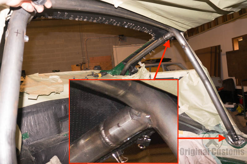
Posted by: Curbandgutter May 14 2017, 09:32 AM
Exactly. Andrew they will be used for the couple of cross bars that will go over the engine/transmission bay. That way when I need to remove the engine and trans, the y come out as a unit over the top. This car is being set up to be able to remove the engine and transaxle easily for servicing.
Posted by: Curbandgutter May 21 2017, 07:11 PM
Some more progress on the transaxle mount. It ended up being very tricky since I did not want the transaxle mounting bolts to have any tension on them. The factory was designed with tension, but since I am adding a much longer ecentricity to the new brace it will add too much tension on the factory bolts. I cam up with a way to tie them together so that there will be zero tension on the bolts. They will only see shear forces. Almost done tying the back end up.
Attached thumbnail(s)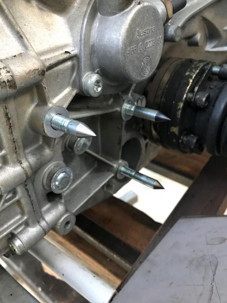
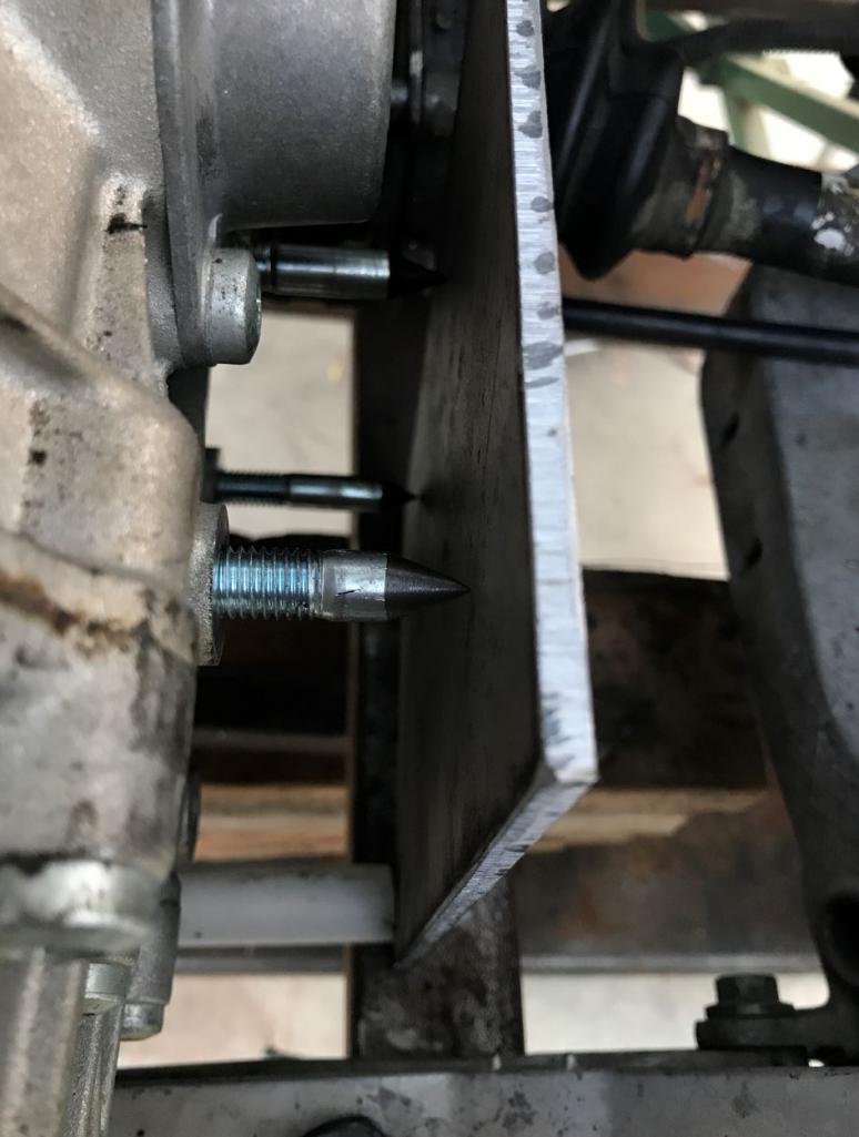
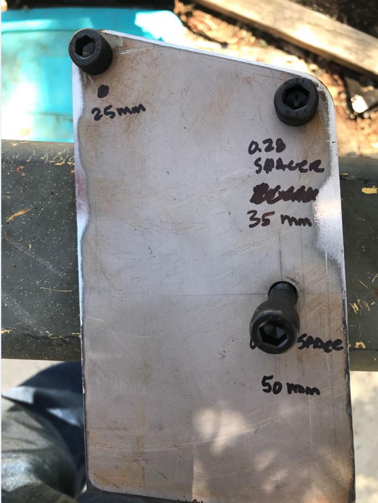
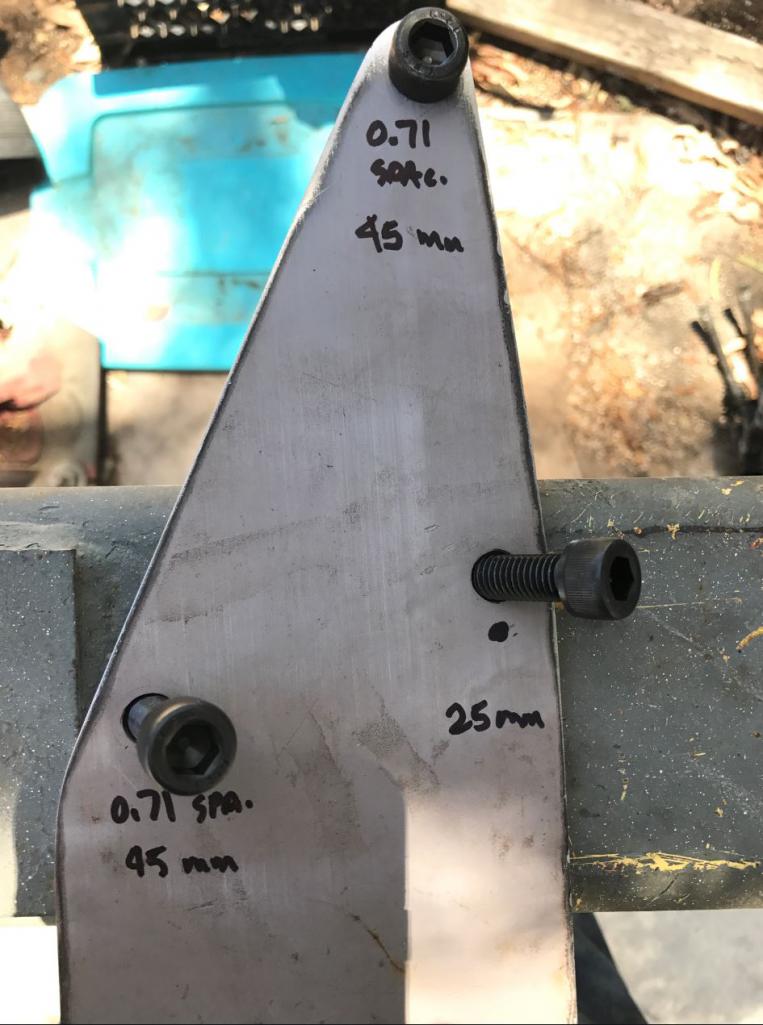
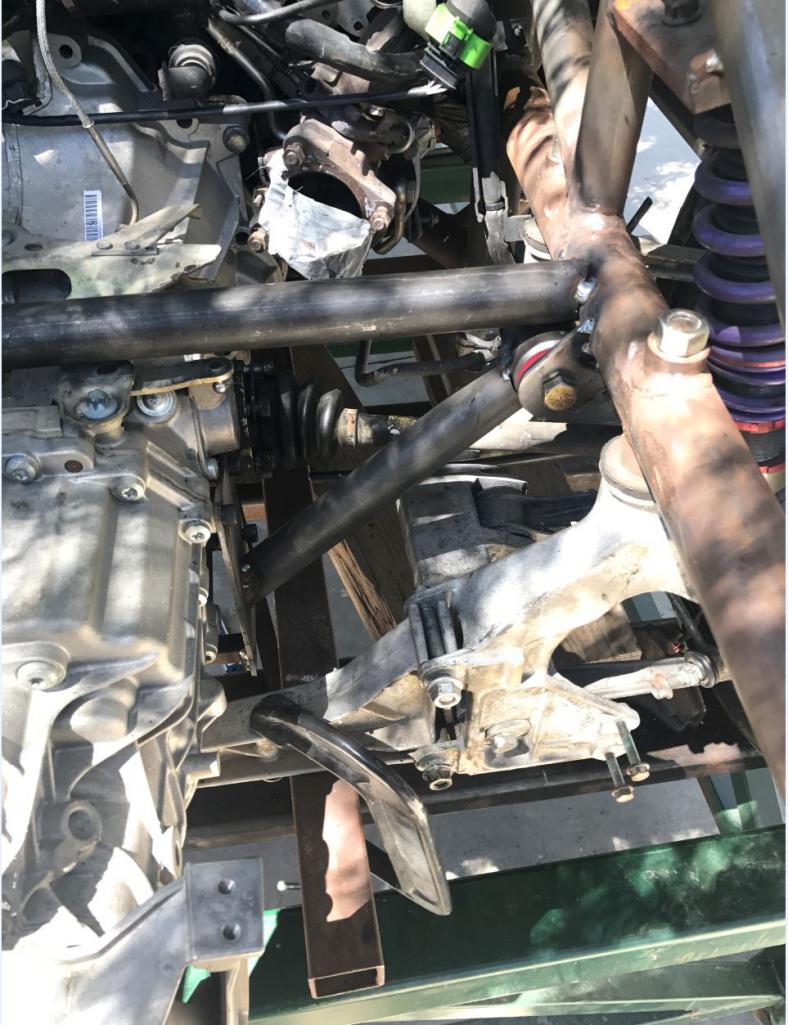
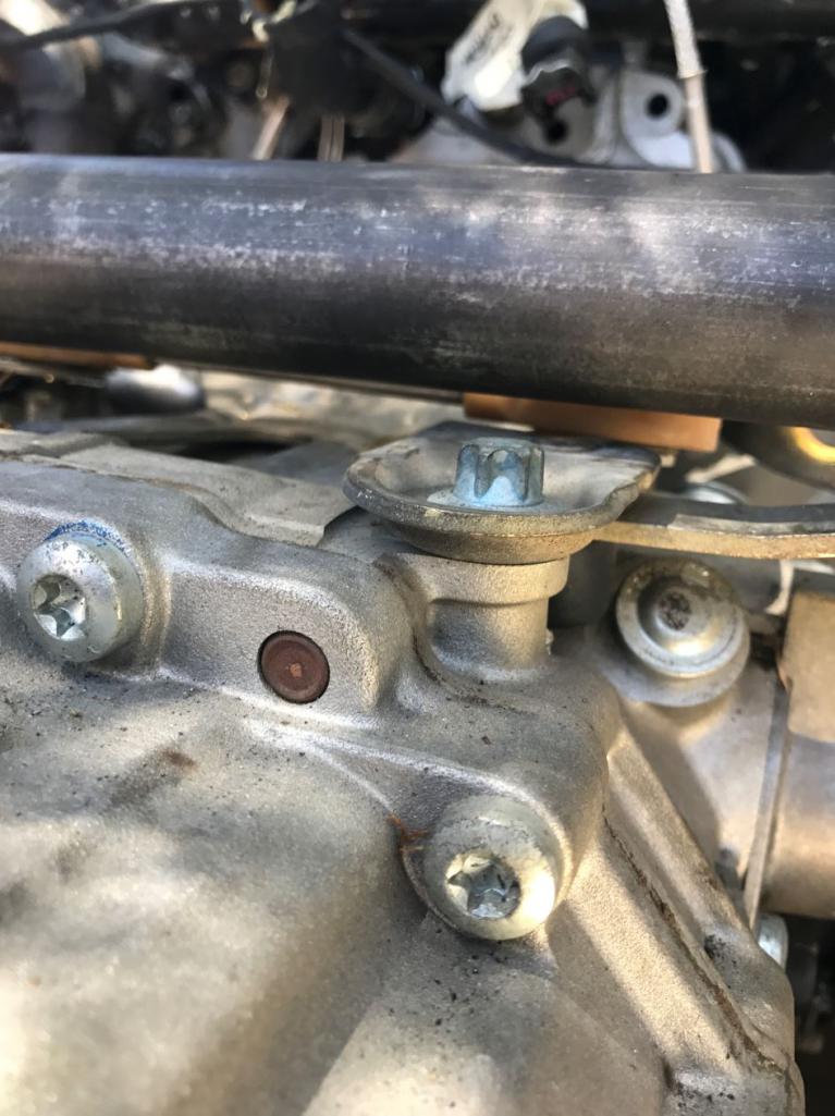
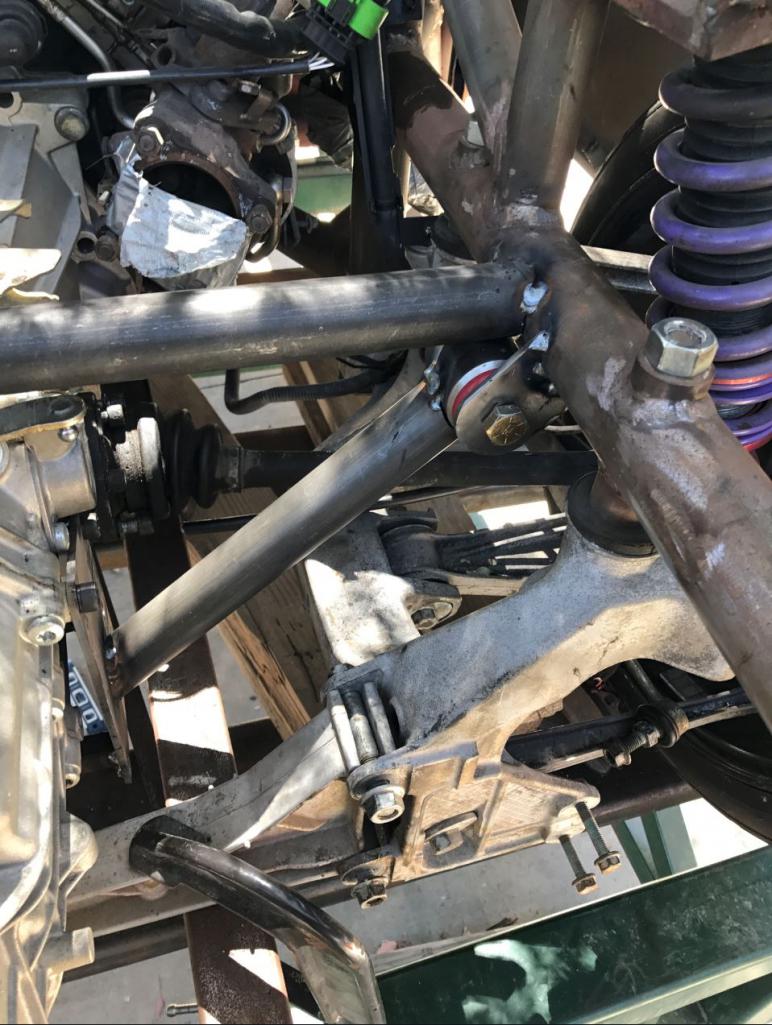
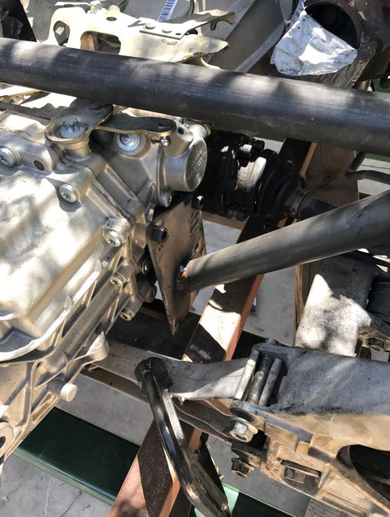
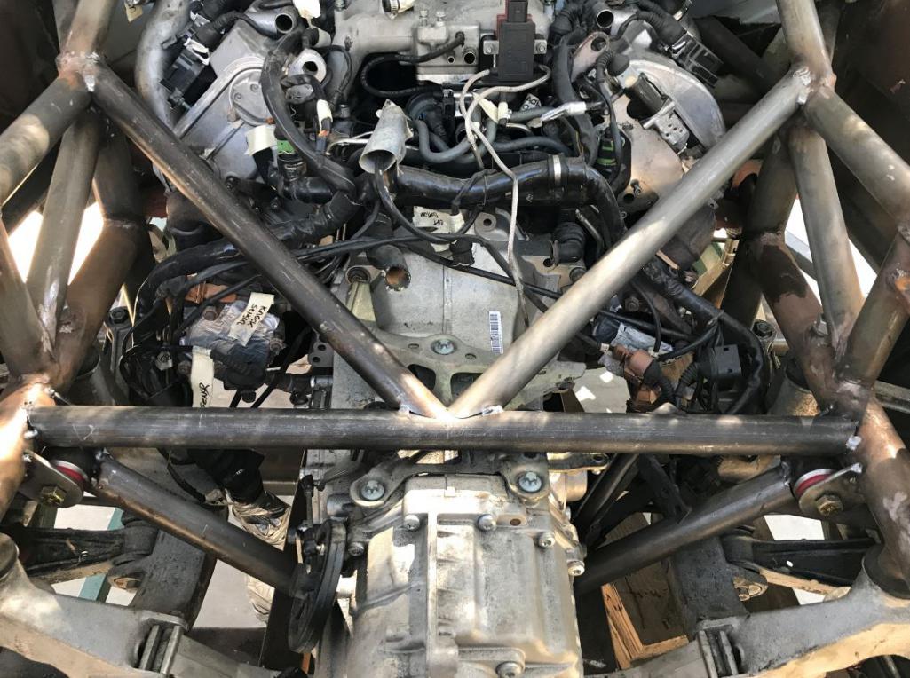
Posted by: Curbandgutter May 24 2017, 09:31 AM
Here is the how I'm doing the front engine mounts. After this weekend I'll be move to the front struts. I need to lower front end 3 inches. I have a solution that keeps the 996 struts and coilovers. If it works out, then the car will have 3 inches of ground clearance but with the stock suspension travel. More on that later.
Attached thumbnail(s)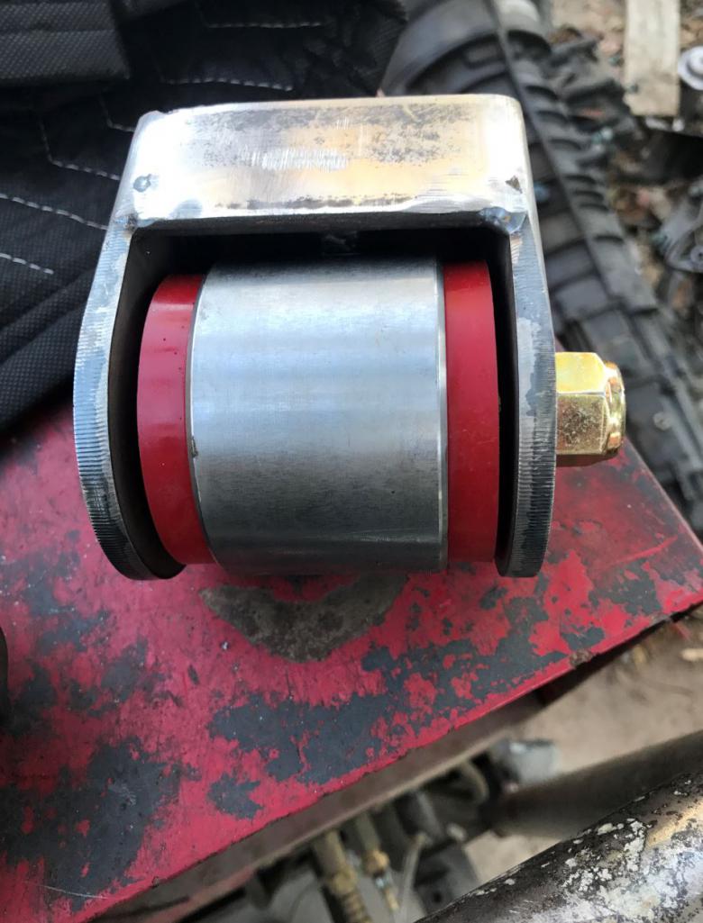
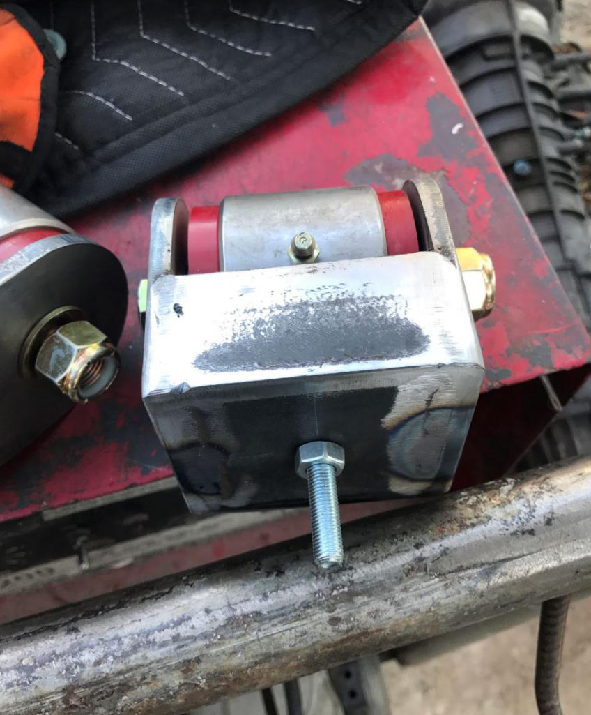
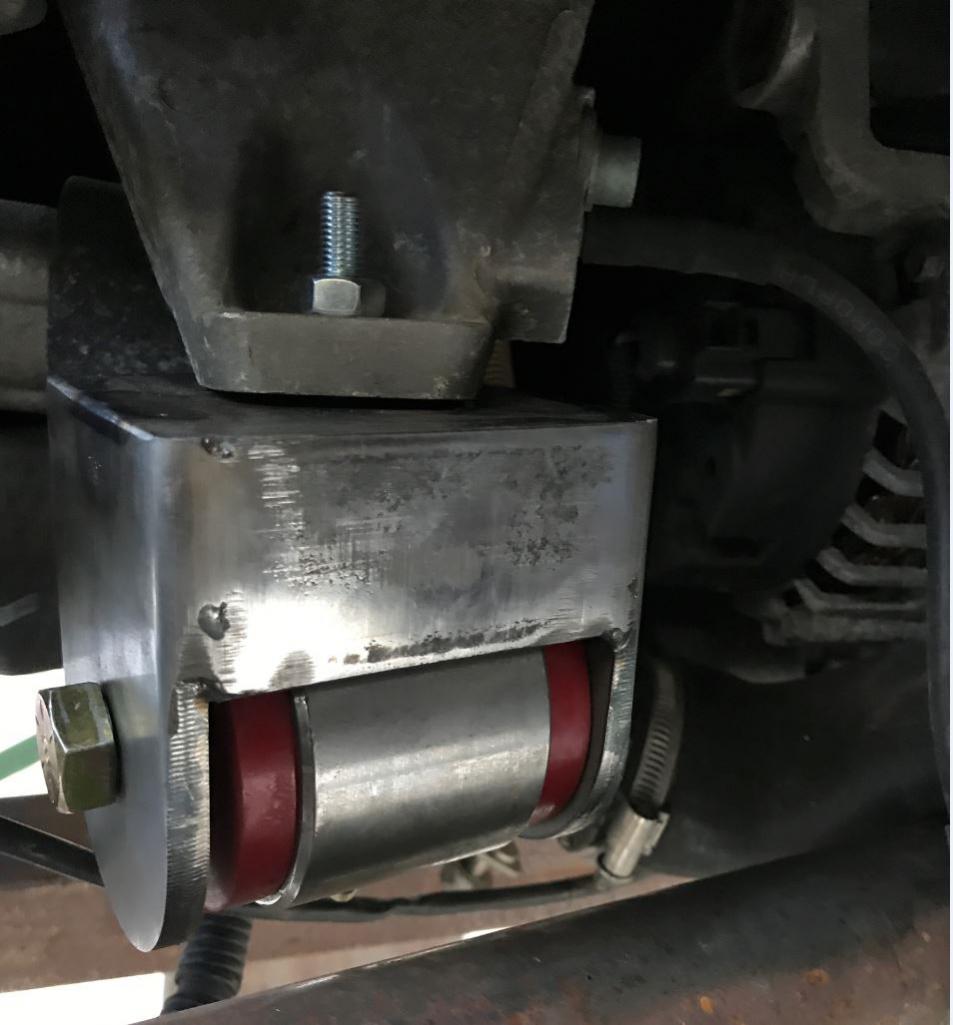
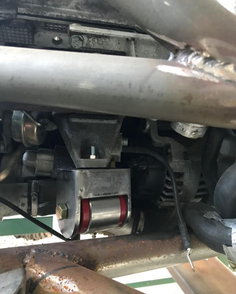
Posted by: Andyrew May 24 2017, 09:40 AM
Here is the how I'm doing the front engine mounts. After this weekend I'll be move to the front struts. I need to lower front end 3 inches. I have a solution that keeps the 996 struts and coilovers. If it works out, then the car will have 3 inches of ground clearance but with the stock suspension travel. More on that later.
Custom lower control arm?
Be sure to drill your hole for the nipple in the stock cast mounting piece. Thats why its not sitting flush
Posted by: Curbandgutter May 24 2017, 10:52 AM
It's not sitting flush cause i haven't tightened the nut. It will sit flush then. You have a good eye Andrew.
Posted by: Curbandgutter May 29 2017, 11:36 AM
OK the engine is finally sitting in its custom engine and transaxle mounts. Took way longer than expected. I still have to complete welding but I have to remove the engine and transaxle for that. Next step is to work on the front struts. I need to lower the ride height 3 inches in the front.
This is the front engine mount.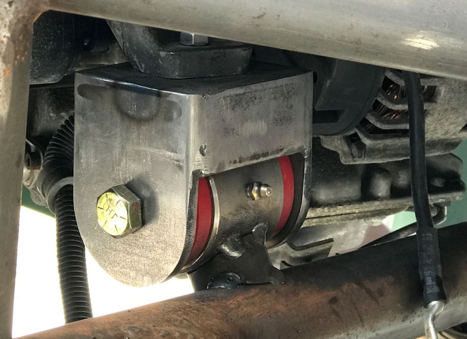
This is the way I tied the transaxle mounts to each other 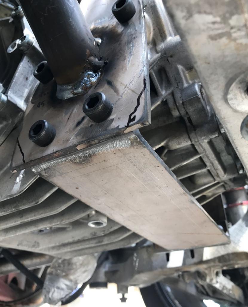
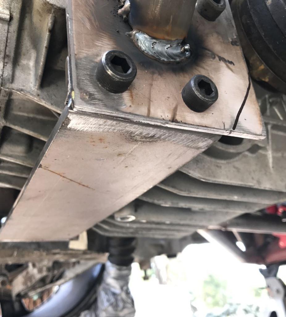
1/2" clearance from the floor pan on both engine and transaxle. They are on the same plane and the motor and transaxle are almost dead level. I will tie the entire bottom of the engine/transaxle bay together with one single aluminum plate across the entire engine/transxle bay opening. It will be tied to the factory suspension bolts and to the tube steel chassis. This will completely tie the opening together and take out any flex in the truss system. The load will then transfer into the floorpan thereby removing any lateral deflection in the chassis. I will also take the opportunity and blend the structural element into a diffuser. 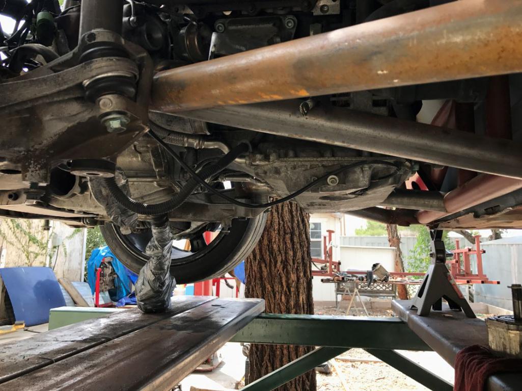
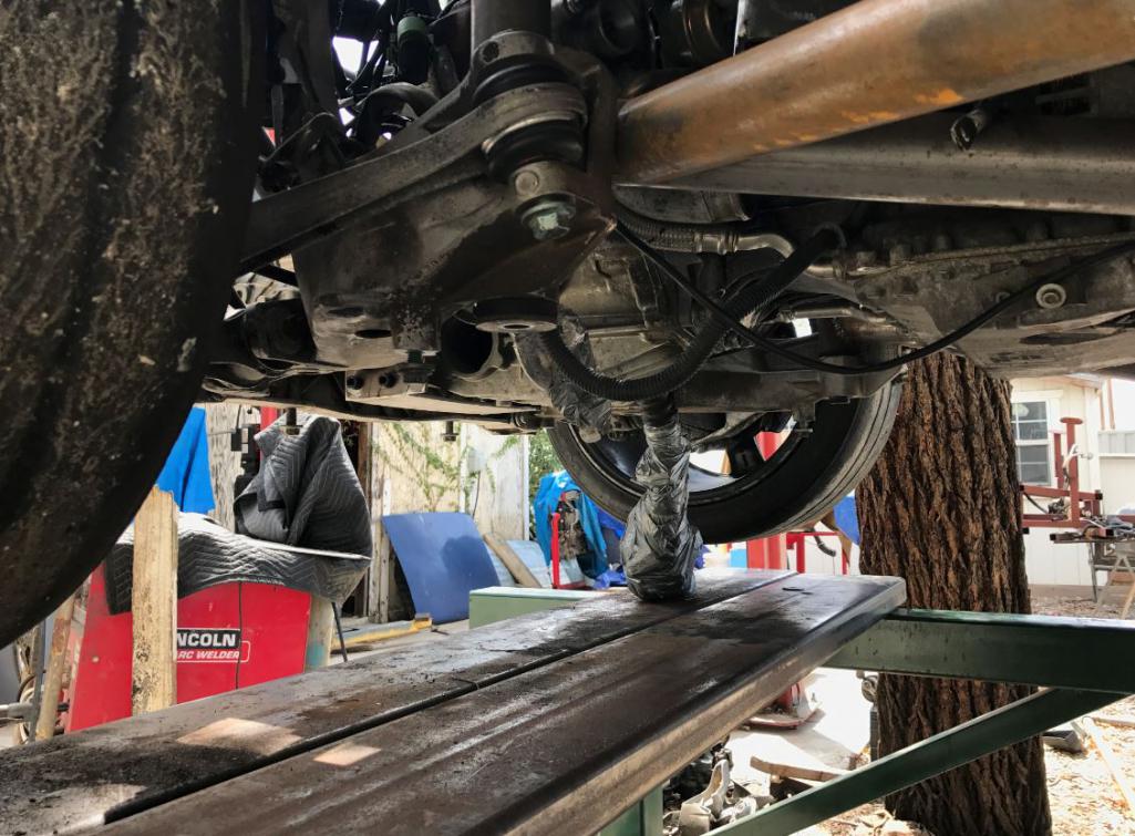
Look at what I picked up. 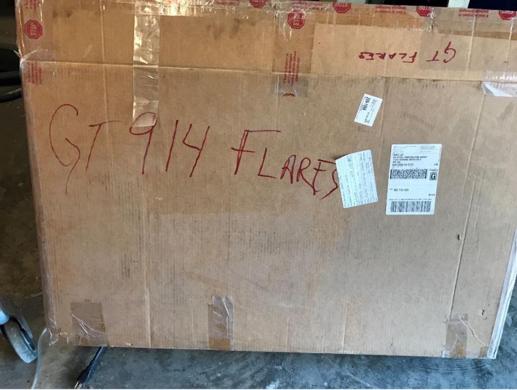
Attached thumbnail(s)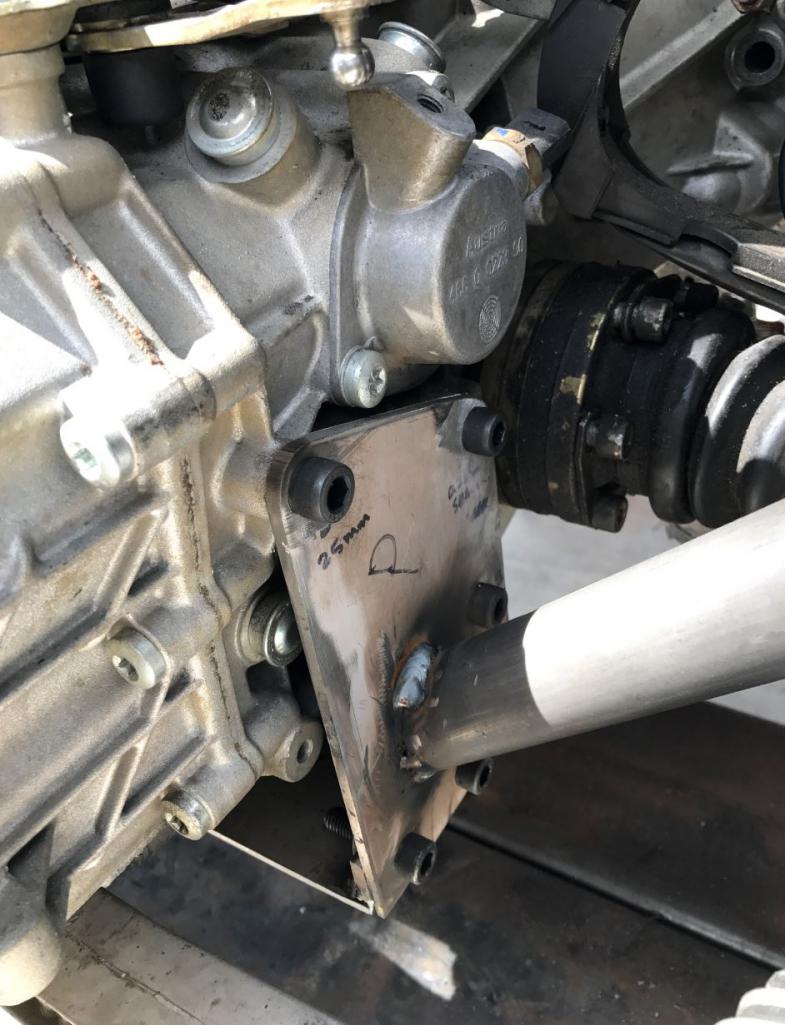
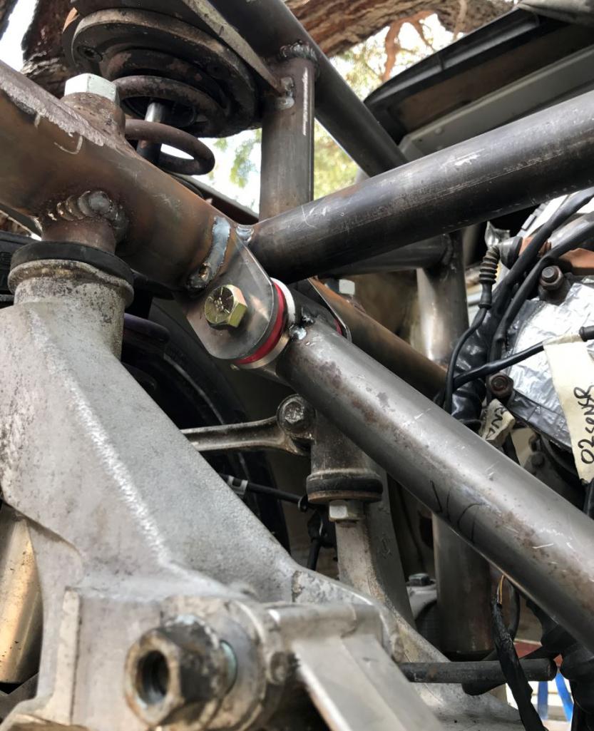
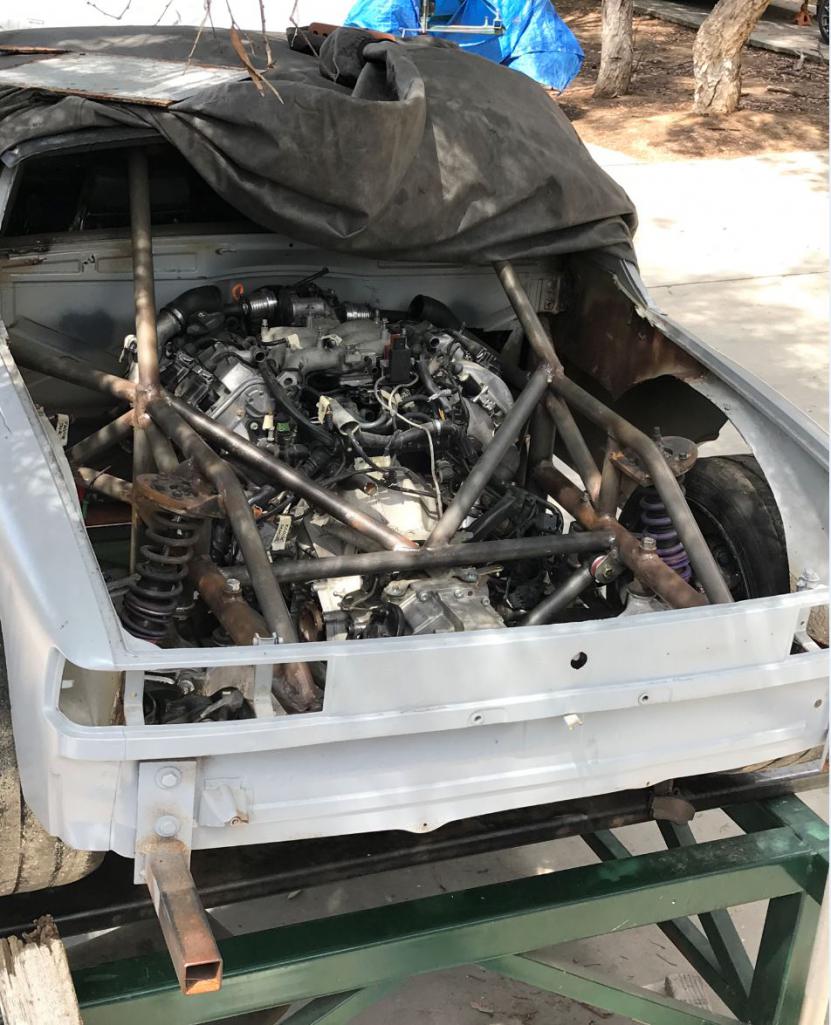
Posted by: sixnotfour May 29 2017, 02:40 PM
flatbar under trans ...looks so ...you finish the sentence....
awesome jiob
Posted by: Curbandgutter May 30 2017, 05:30 PM
flatbar under trans ...looks so ...you finish the sentence....
awesome jiob
efficient? I don't know how would you end it? Seems like you have something in mind.
Posted by: Andyrew May 30 2017, 05:39 PM
Seems like a nice place to mount the diffuser to me
Posted by: Curbandgutter Jun 2 2017, 10:06 AM
Seems like a nice place to mount the diffuser to me
Close but not low enough. The diffuser will be about a 1/4" lower.
Posted by: Curbandgutter Jun 2 2017, 10:19 AM
Well now that I'm moving on to the front struts, I know that I need to lower the ride height 3" in the front. So I started to think how I can determine how much I can raise the strut tower up into the hood while using the 996 coil overs and thereby having a lowered car while retaining the stock ride and adjust ability. I'm shooting for 4" of clearance to the pinch weld of the longs.
Well I went to a hobby store and bought some foam that they use in flower shops. Then I cut and sandwiched the foam in between the strut tower and the hood. Then I closed the hood and I got the mold that I needed. Kind of like pressing a panini.
Here is the mold after pressing it. 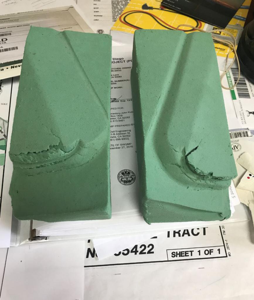
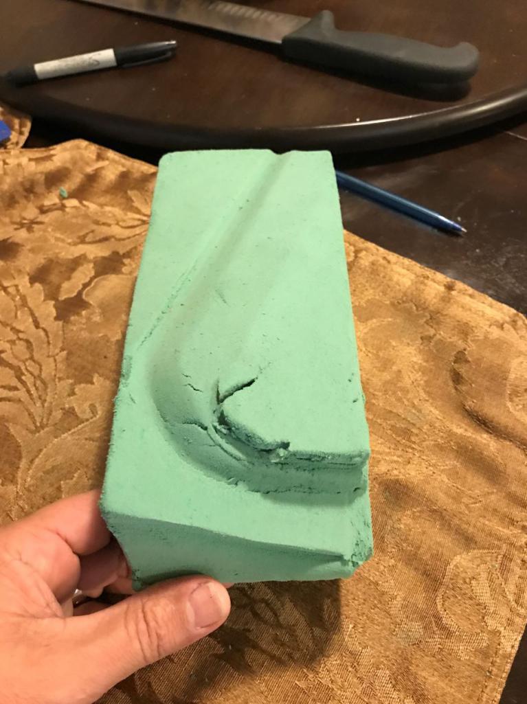
Here is the bottom view 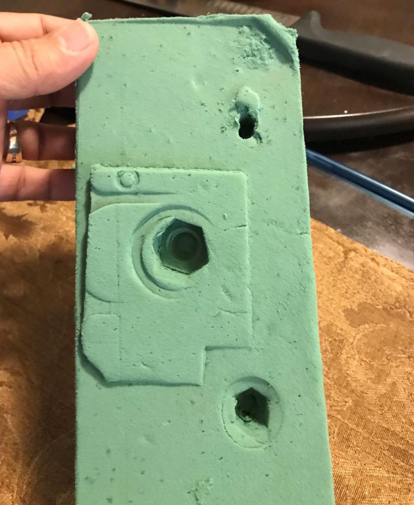
Then slice at the bolt locations and get the clearance dimensions from the hood. Looks like I will be able to shove the struts up into the trunk another 2 inches. 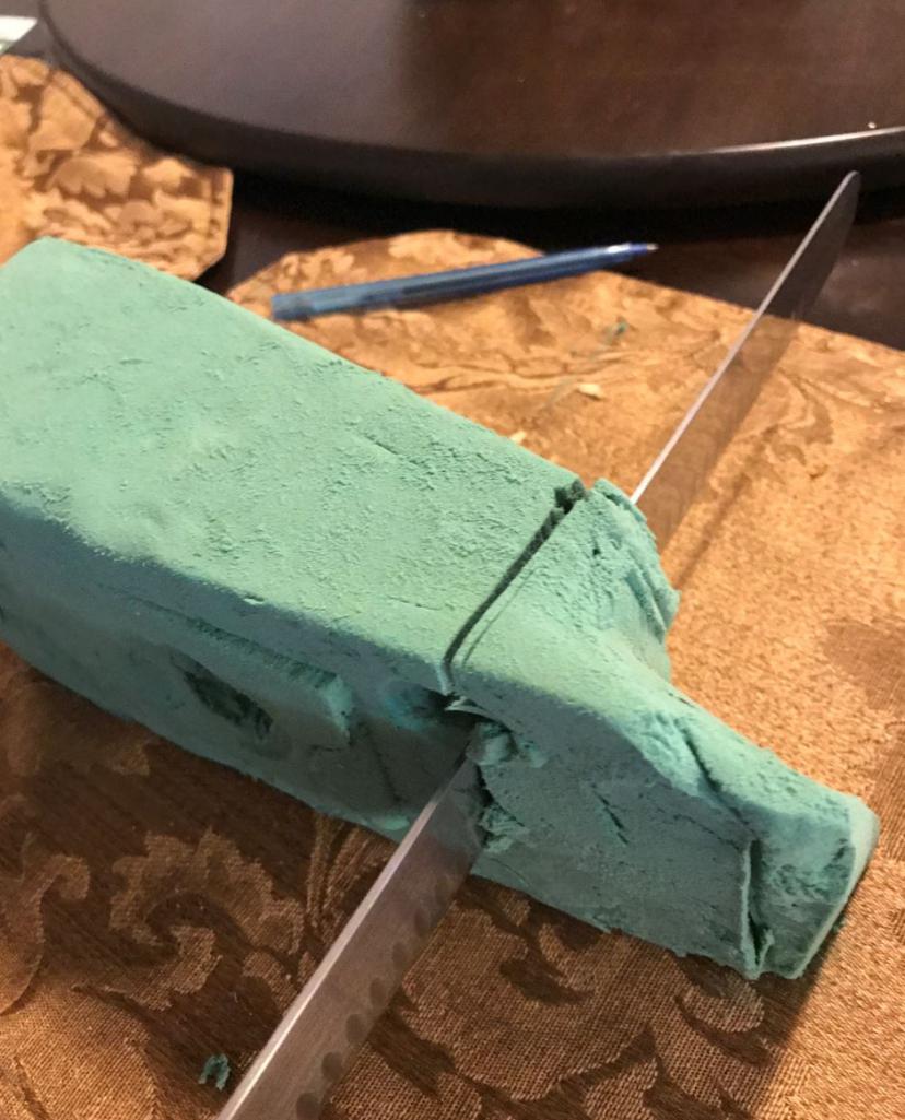
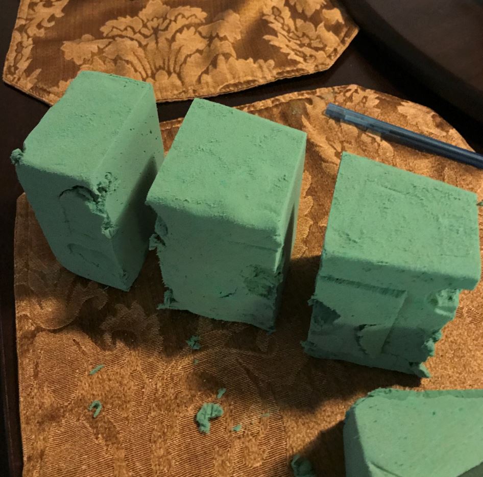
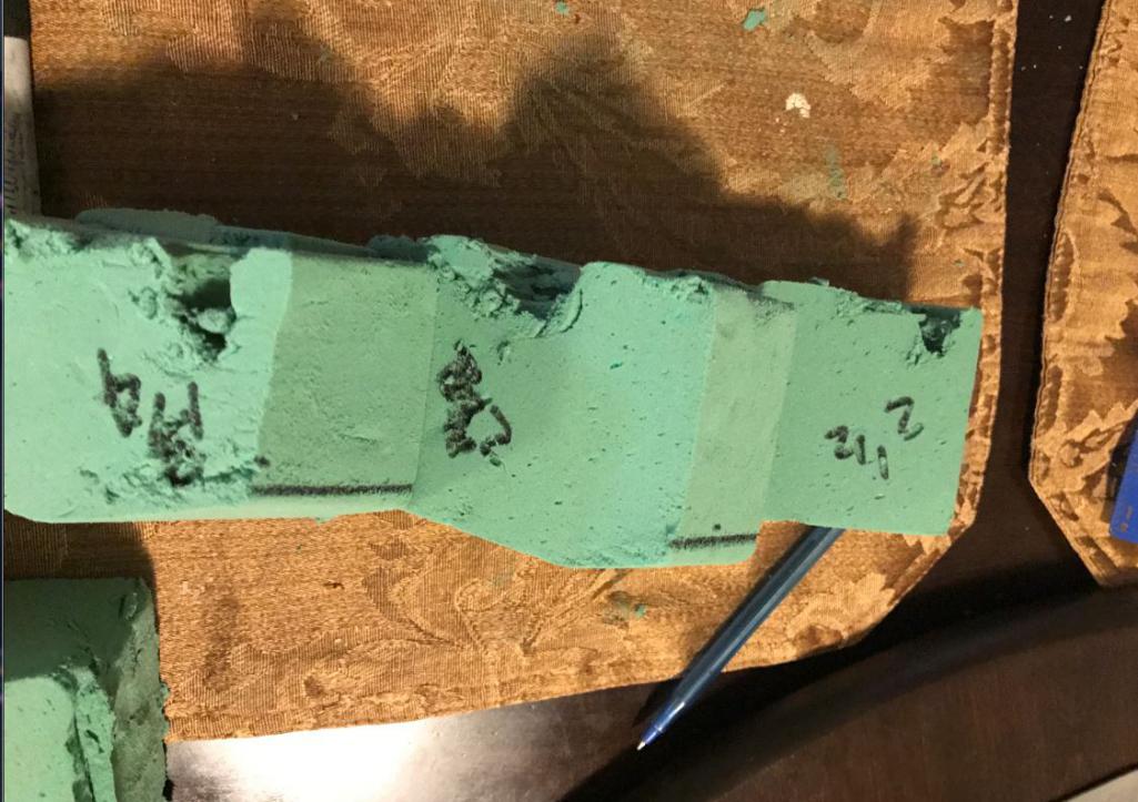
And that's how you slice it.
Now I need CSDilligaf to machine the shoulder of the lower strut to be able slide into lower strut mounting point another 1 inch. Then I'll have my 4" of clearance "unloaded".
Posted by: Curbandgutter Jun 29 2017, 05:45 PM
Tomorrow I'm going to Chips place and he is going to put the lower coilover in his lathe and cut out enough meat to lower the base of the strut 1 1/4" into the aluminum 996 upright. I'll be finishing this portion of the build this weekend and will post pictures of it sitting at the correct ride height. It will have 4" of clearance on the front and 4 1/2 on the rear without lowering from its stock position.
This is where the strut installs into the aluminum upright 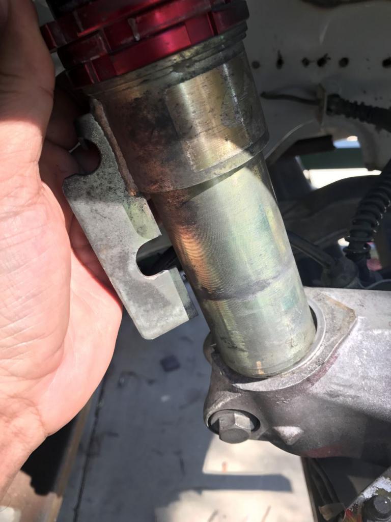
This is where we are machining the strut to be able to lower it 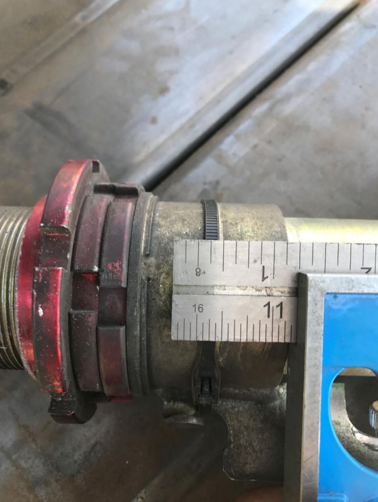
This is what the center console will look like. I'll be able to
run all of my wiring and piping through here. It will be covered
in carbon fiber and will be removable for access. This will add
extra rigidity to the frame as well. 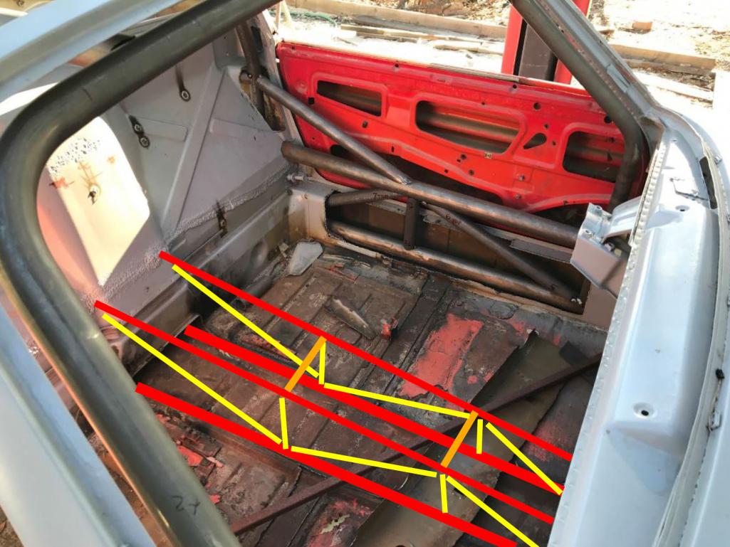
I'll post pics once it's sitting on it's own weight. Next step will be to remove engine and suspension and finish welding everything up, add the center console. Will be ordering floor after the 4th and then install that as well.
Posted by: tygaboy Jun 29 2017, 07:43 PM
Nice! You're inspiring me to get back working on mine. I, too, have a custom center tunnel to fabricate... Great minds, eh?
Posted by: Curbandgutter Jul 3 2017, 12:48 PM
Nice! You're inspiring me to get back working on mine. I, too, have a custom center tunnel to fabricate... Great minds, eh?
Yes that center tunnel is going to be very effective in torsion and very useful for the shifter console support and to serve as a conduit for all hoses i.e. fuel, radiator, brake, AC and electric.
Glad to see yo back on your project. I know how it is when you hurt your shoulder. Last year in May I destroyed my right shoulder due to a fall on concrete while pulling some hoses tripping backwards. I did everything I could with that one shoulder to keep me form falling on the 996 front suspension that was on the ground. I tore all kinds of stuff on my shoulder. I had to use my left hand to move my right arm so that I could work on ACAD. I still worked on the car since all of the work was below the waist. I'm about 70% now one year later.
Posted by: Curbandgutter Jul 3 2017, 12:57 PM
STANCE........CHECK
Front 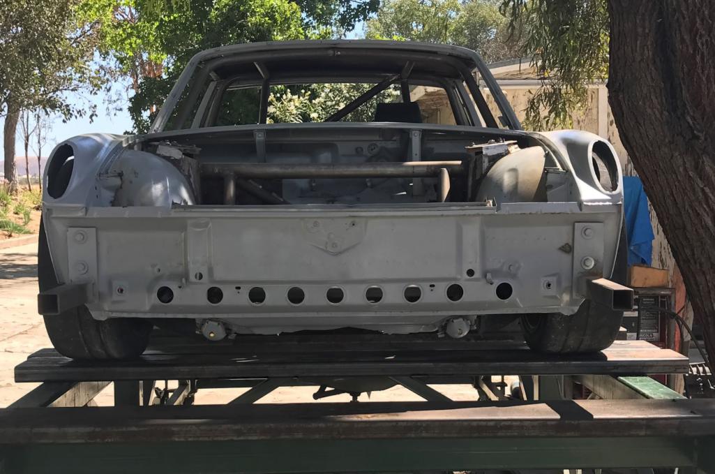
Rear 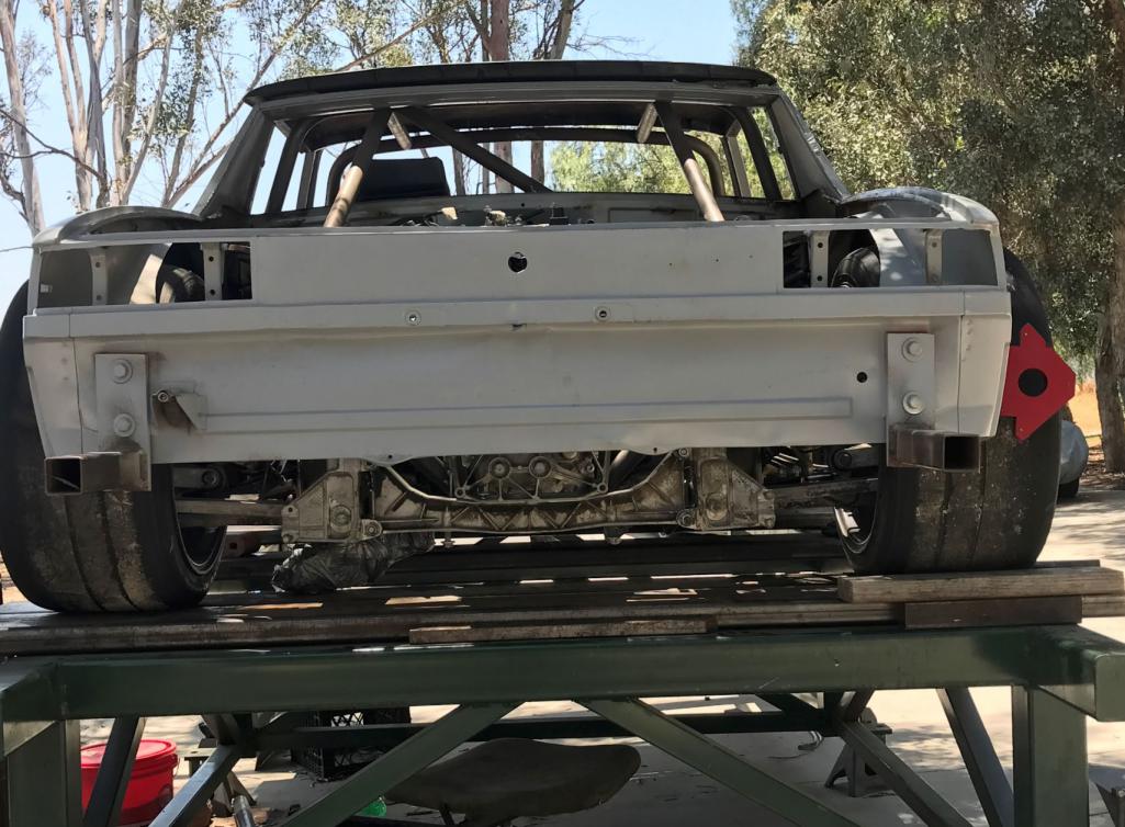
Side Shot Before 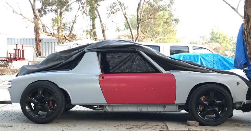
Side Shot After 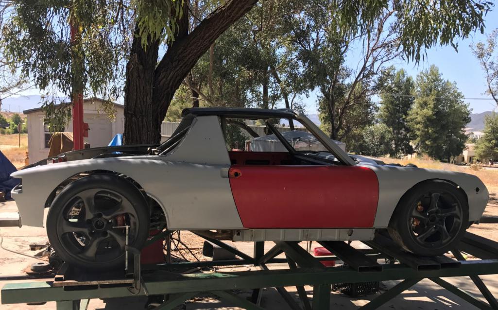
Shot of strut after Chip machined it.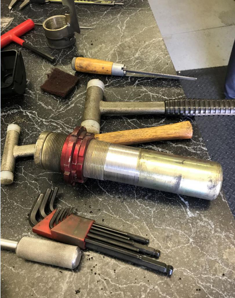
Clearance at front 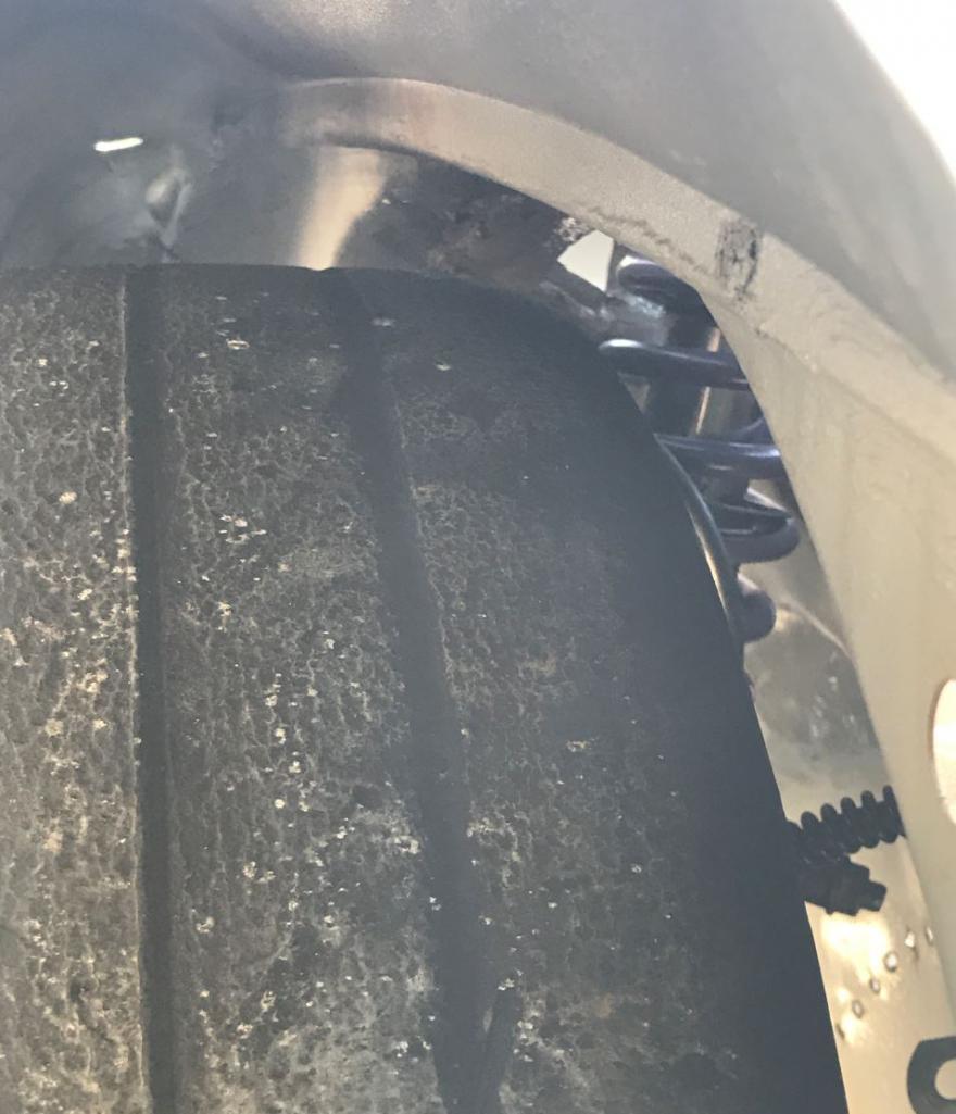
Attached thumbnail(s)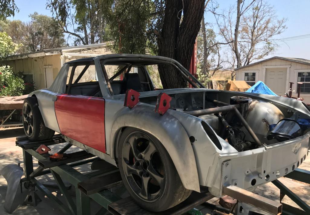
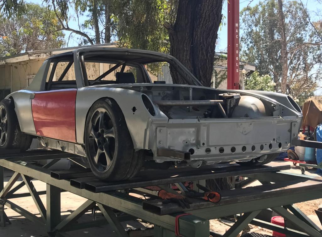
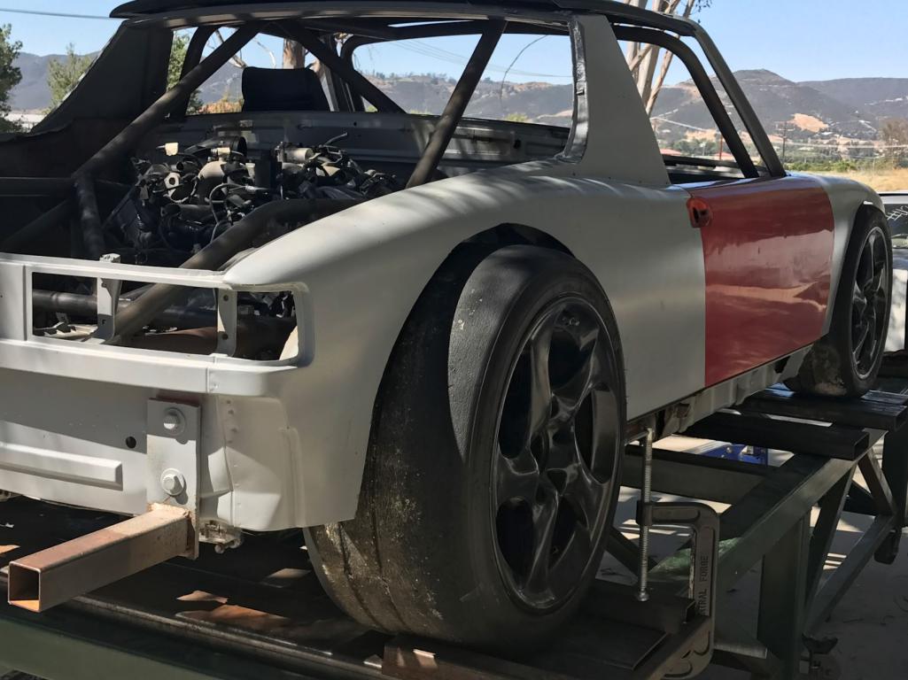
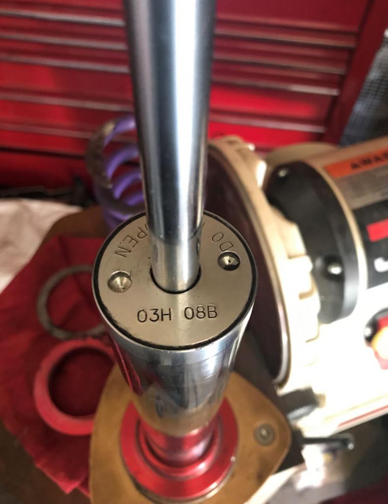
Attached image(s)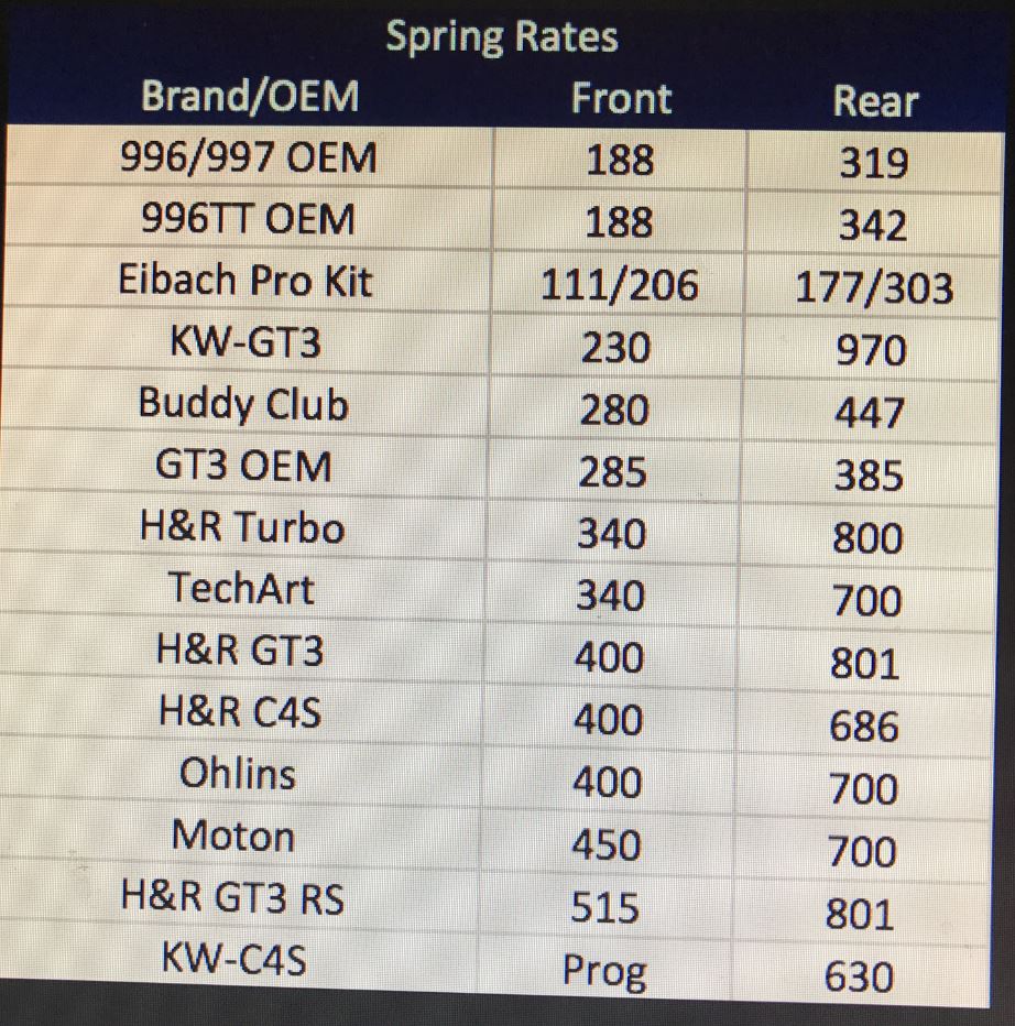
Posted by: Curbandgutter Jul 7 2017, 10:22 AM
These two pics show a little bit better how much the car was lowered. All measurements are to the doughnuts
BEFORE 7 1/2"Front, 7" rear 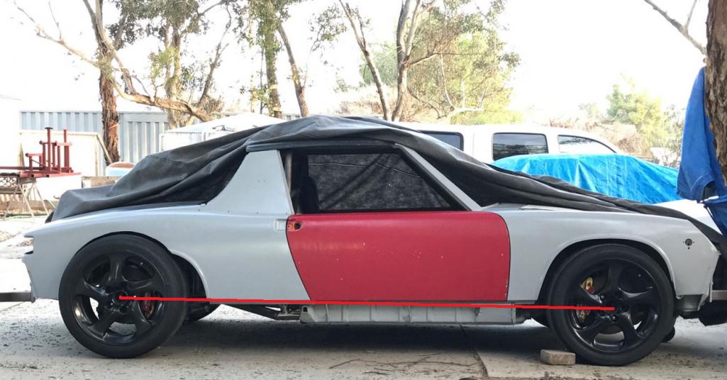
AFTER 4" Front, 4 1/2" rear 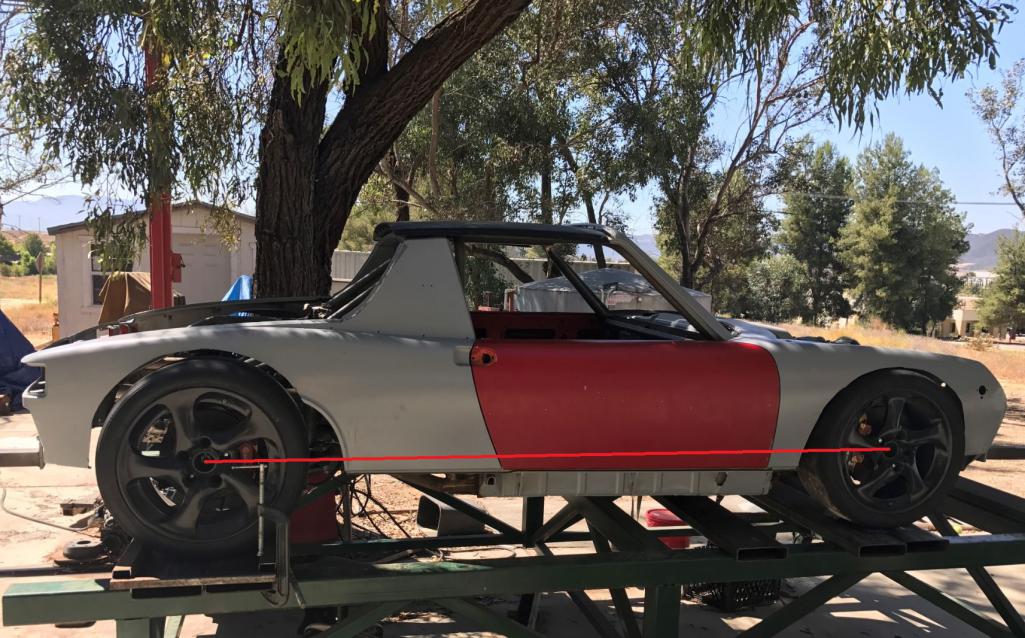
Posted by: Andyrew Jul 7 2017, 11:40 AM
Significant! Thats right where it needs to be. With the longer wheelbase it will look even lower!
Posted by: 76-914 Jul 7 2017, 12:12 PM
Looks good with that flare on, Rudy. Will the flare work on the rear or will you need to add some steel to extend the rear flare out a bit? How much will a set of tires that can handle that speed cost you?
Posted by: csdilligaf Jul 7 2017, 12:44 PM
That does look good Rudy. Now on to buttoning up some area's that need welding and fill in some sheet metal and you'll sitting pretty good.
Posted by: Curbandgutter Jul 7 2017, 01:05 PM
Significant! Thats right where it needs to be. With the longer wheelbase it will look even lower!
Thanks Andrew. Yes it is significant.
Posted by: Curbandgutter Jul 7 2017, 01:09 PM
Looks good with that flare on, Rudy. Will the flare work on the rear or will you need to add some steel to extend the rear flare out a bit? How much will a set of tires that can handle that speed cost you?
Kent, I will need to add two inches to the front fender and then weld the 916 fender to the expanded front fender. The rear will need to be widened 3 inches before adding the rear 916 flares.
Im picking up 19x9" front rim and 19X13' rear rim. The rolling diameter will be less than a stock 914. I've got a deal worked out on modular 3 piece forged wheels. Tires will be around $1,200.
Chip you have first dibs on my 997 hollow spokes.
Posted by: jd74914 Jul 7 2017, 01:10 PM
Very nice! It looks awesome Rudy!!
Posted by: Curbandgutter Jul 7 2017, 01:15 PM
That does look good Rudy. Now on to buttoning up some area's that need welding and fill in some sheet metal and you'll sitting pretty good.
Yep i just added the removable strut across the transaxle and will now take everything apart, put on rotisserie, replace floor, add center tunnel and finish welding the chassis as well as plugging up all of the "access" holes. Then I will do the final TWIST test. I'll be sandblasting all of the tube steel and epoxy them as well. Then install radiator, fuel tank, pedal assembly and electrical. I've got alot of work still ahead, but the major labor portion is almost out of the way.
Posted by: ValcoOscar Jul 7 2017, 02:16 PM
Rudy-
I'm in awe...
Just amazing progress thus far.
It already looks scary fast.
Keep going my friend....
Oscar
Posted by: Andyrew Jul 7 2017, 02:26 PM
Looks good with that flare on, Rudy. Will the flare work on the rear or will you need to add some steel to extend the rear flare out a bit? How much will a set of tires that can handle that speed cost you?
Kent, I will need to add two inches to the front fender and then weld the 916 fender to the expanded front fender. The rear will need to be widened 3 inches before adding the rear 916 flares.
Im picking up 19x9" front rim and 19X13' rear rim. The rolling diameter will be less than a stock 914. I've got a deal worked out on modular 3 piece forged wheels. Tires will be around $1,200.
Chip you have first dibs on my 997 hollow spokes.
13's??? Damn. Making me look bad!!
I wish I had more rear rubber than my 10's, 13" would be very nice. run some 335's. This chassis really needs the extra mechanical grip as it doesnt have the weight to put the necessary force on the tires.
Posted by: Curbandgutter Jul 7 2017, 03:39 PM
Looks good with that flare on, Rudy. Will the flare work on the rear or will you need to add some steel to extend the rear flare out a bit? How much will a set of tires that can handle that speed cost you?
Kent, I will need to add two inches to the front fender and then weld the 916 fender to the expanded front fender. The rear will need to be widened 3 inches before adding the rear 916 flares.
Im picking up 19x9" front rim and 19X13' rear rim. The rolling diameter will be less than a stock 914. I've got a deal worked out on modular 3 piece forged wheels. Tires will be around $1,200.
Chip you have first dibs on my 997 hollow spokes.
13's??? Damn. Making me look bad!!
I wish I had more rear rubber than my 10's, 13" would be very nice. run some 335's. This chassis really needs the extra mechanical grip as it doesnt have the weight to put the necessary force on the tires.
Andrew you hit the nail on the head.
Mechanical grip is what I'm after cause pure friction is just a function of weight. And I this car won't have that much weight to transfer.
Posted by: plays with cars Dec 30 2017, 03:51 PM
Ok, I just finished binge reading this build story and am in awe of the vision, skill, and perseverance to make this happen. But, come on! You can't leave it hanging... must have an update on progress.
Posted by: Curbandgutter Mar 7 2018, 03:42 PM
Ok, I just finished binge reading this build story and am in awe of the vision, skill, and perseverance to make this happen. But, come on! You can't leave it hanging... must have an update on progress.
Sorry for the long delay but I am happy to say that I've been back at it after a slight break and will have an update shortly. I've also had some time to think over some design elements and decided to remove the air scoops over the roof. I decided to stick with the hollow spoke turbo twists and I'm looking into placing the twin 996 radiators in the quarter panel. As you may know, I lengthened the wheelbase 3" and that will hopefully give me room to fit the radiators. I'm trying to not have to have radiators in the front hood.
Posted by: ValcoOscar Mar 7 2018, 03:49 PM
Nice...welcome back
We missed you

Oscar
Posted by: sb914 Mar 7 2018, 04:32 PM
Glad to hear your back Rudy! Hope everything's going well!
Posted by: tygaboy Mar 7 2018, 04:56 PM
He's BAAAAAaaaaak!
OK, enough with the celebrating. Let's see some progress and pics.
Posted by: 76-914 Mar 7 2018, 09:16 PM
Good to hear, Rudy. I was going to stop by last week but figured if you didn't have enough time to work on your car then you sure didn't have enough time to chew the fat!
Posted by: Curbandgutter Aug 22 2018, 04:21 PM
OK back on FINALLY! I started work on the floor. I removed it and now am waiting to get the replacements. I will be working on closing up the holes that I needed to put the struts through. Also, it's easier with the floor off. Should be getting a new set of shoes. 10.5 x 18 F, 15mm offset with 265/35/18 and 12.5x 18 rear, 0 mm offset with 335/35/18 Toyo R888R's. Track is 62.5" Front, Rear is 63.0".
Attached thumbnail(s)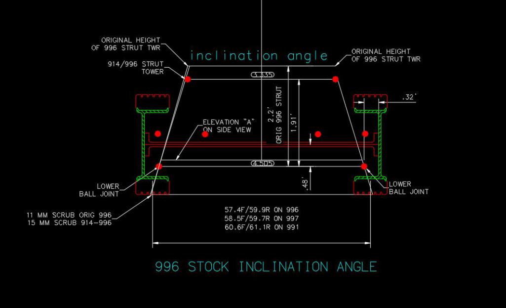
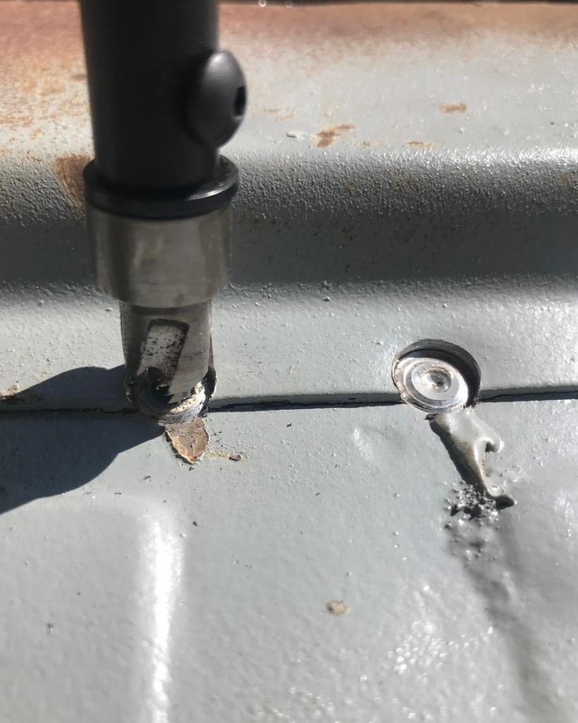
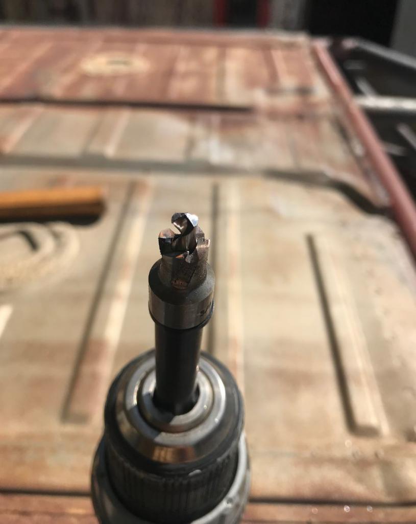
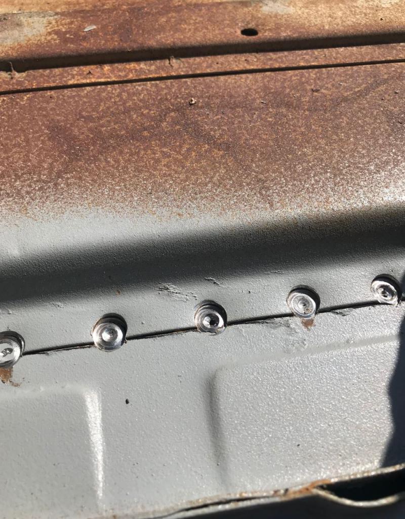
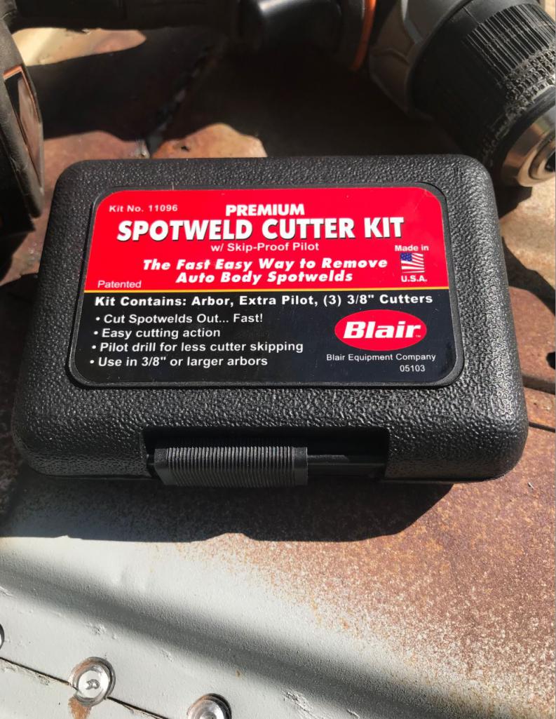
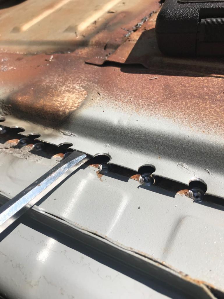
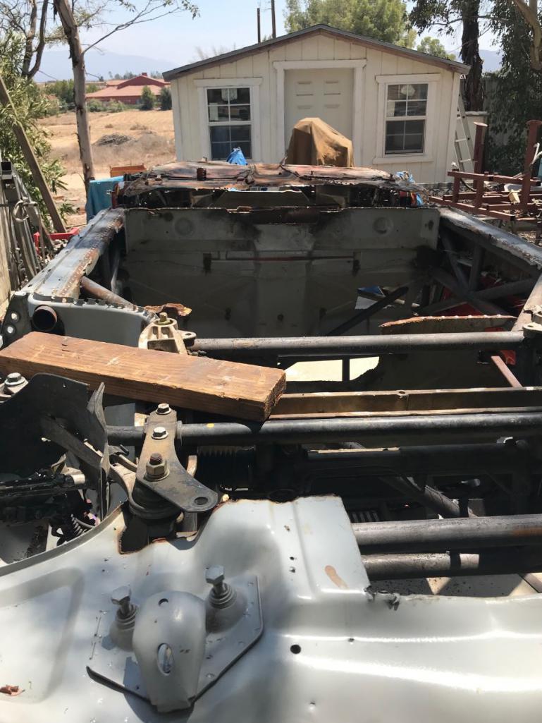
Attached image(s)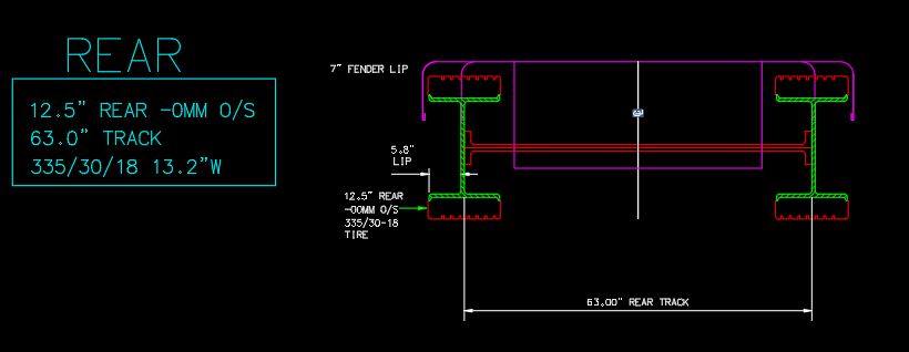
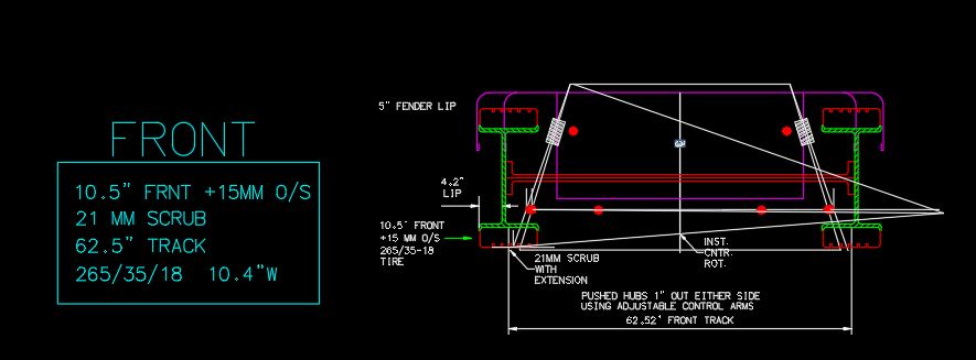
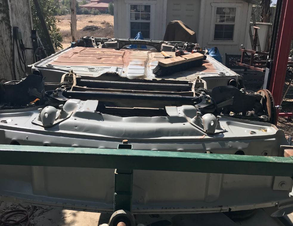
Posted by: Andyrew Aug 22 2018, 04:43 PM
Awesome! Whats the plan with the floor pan? Going to lower it some for headroom?
Posted by: sb914 Aug 22 2018, 04:45 PM
What up Rudy?
Posted by: 76-914 Aug 22 2018, 05:03 PM
Are you working on it Saturday. I'll stop by if so.
Posted by: ValcoOscar Aug 22 2018, 05:54 PM
A big welcome back Rudy!!!!


Posted by: tygaboy Aug 22 2018, 06:33 PM
Yea, Rudy! Welcome back!
Posted by: Curbandgutter Aug 24 2018, 11:57 AM
Thanks for the awesome welcome back. @http://www.914world.com/bbs2/index.php?showuser=172 @http://www.914world.com/bbs2/index.php?showuser=15191 @http://www.914world.com/bbs2/index.php?showuser=9964 @http://www.914world.com/bbs2/index.php?showuser=16669 @http://www.914world.com/bbs2/index.php?showuser=19241 Andy I'm just going to put the stock floor back in since the car is already low (4" clr) I don't want to expose my hindquarters and moneybags any more than it alreasy is. Kent, It would be better if you came by on the weekend after labor day. I should have the floor by then and will be installing it. Hopefully the new wheels will be in at that time as well. The break has been good, I've though over some things, changed my mind over and over but now I feel way better about some of the design changes. I am going with the radiators in the quarter panels and I decided against (for the second time) the hollow spokes.
By the way did you guys notice the front and rear track dimensions. It's a half inch from being 63" Square.
Posted by: Curbandgutter Aug 24 2018, 12:07 PM
BTW does someone have the link to the guy that shows how to widen the steel gt flares? I've checked using the search but I was not successful. I remember that he cut the whole thing and added a strip to it. I will need to do the same thing and is the next thing on my agenda after the floor is welded back in.
Posted by: tygaboy Aug 24 2018, 02:39 PM
Rudy - here's a pic that @http://www.914world.com/bbs2/index.php?showuser=209 posted on my thread about a flare widening update he did. Maybe check in with him.
Attached image(s)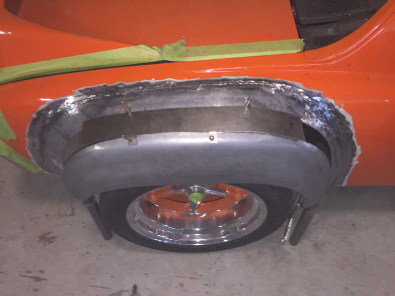
Posted by: siverson Aug 24 2018, 04:05 PM
Sweet - looks good. What software are you using for the front/rear track diagrams?
-Steve
Posted by: Curbandgutter Aug 24 2018, 04:30 PM
Sweet - looks good. What software are you using for the front/rear track diagrams?
-Steve
Autocad
Posted by: Curbandgutter Aug 24 2018, 04:30 PM
Rudy - here's a pic that @http://www.914world.com/bbs2/index.php?showuser=209 posted on my thread about a flare widening update he did. Maybe check in with him.
Thanks I will look him up.
Posted by: Curbandgutter Aug 24 2018, 05:12 PM
Rudy - here's a pic that @http://www.914world.com/bbs2/index.php?showuser=209 posted on my thread about a flare widening update he did. Maybe check in with him.
@http://www.914world.com/bbs2/index.php?showuser=209 would you happen to have more pictures of that flare widening? I searched your name and widen flares and did not come up with what I was looking for.
Posted by: Rand Aug 24 2018, 05:19 PM
Love how the new @ things are working.
Posted by: ChrisFoley Aug 24 2018, 07:56 PM
would you happen to have more pictures of that flare widening? I searched your name and widen flares and did not come up with what I was looking for.
I have a collection of pics in my office computer showing more details. I don't recall if I ever posted more of them on the forum. Just checked my facebook company page but only a couple incidental pics of that car in the timeline photos.
Posted by: Curbandgutter Aug 25 2018, 02:05 PM
would you happen to have more pictures of that flare widening? I searched your name and widen flares and did not come up with what I was looking for.
I have a collection of pics in my office computer showing more details. I don't recall if I ever posted more of them on the forum. Just checked my facebook company page but only a couple incidental pics of that car in the timeline photos.
@http://www.914world.com/bbs2/index.php?showuser=209 I would appreciate it if you could post up a bunch of those pictures to get an idea of how you did it.
Posted by: mepstein Aug 25 2018, 02:20 PM
Ron S did it on his real 6.
http://www.914world.com/bbs2/index.php?showtopic=69303&hl=flares
Attached image(s)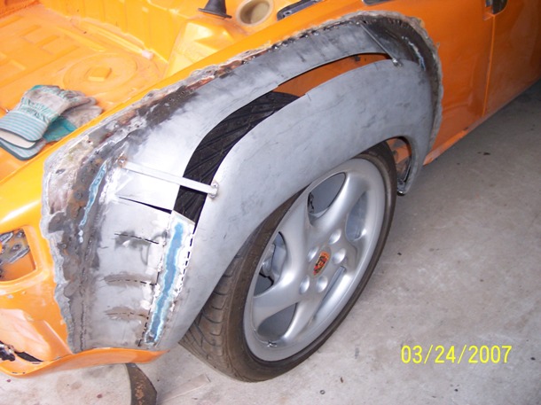
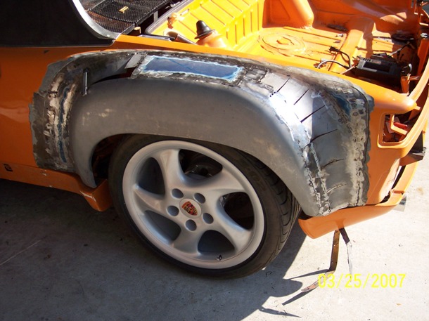
Posted by: Curbandgutter Aug 25 2018, 03:14 PM
Ron S did it on his real 6.
http://www.914world.com/bbs2/index.php?showtopic=69303&hl=flares
@http://www.914world.com/bbs2/index.php?showuser=10825 Thank you so much......that was perfect.
Posted by: ChrisFoley Aug 25 2018, 03:45 PM
I went thru all my pics. Most of the work is undocumented.
The process started with cutting off some crappy custom flares that had really thick bondo to make them smooth.
Then I carefully butt welded the AA GT flares in place and hammered the weld seams smooth.
Next I chose a cut line just inside the curved edge. The location was chosen so I could shrink the edge of the removed piece to match the new shape.
Then, using a modified palm nailer, I hammered the shit out of the part left on the car to raise up the top so the wheel opening would end up at the same height as on the stock flare, and I smoothed all the surfaces with hammer and dolly.
The front and rear edges were curved outward to create a smooth shape that would line up with the reworked edge of the removed piece.
After many hours of reshaping the loose edge I was satisfied with the transition and clecoed the loose section in place with some small pieces of sheet metal to bridge the gap.
This is the point where I started taking pictures.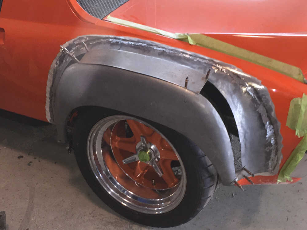
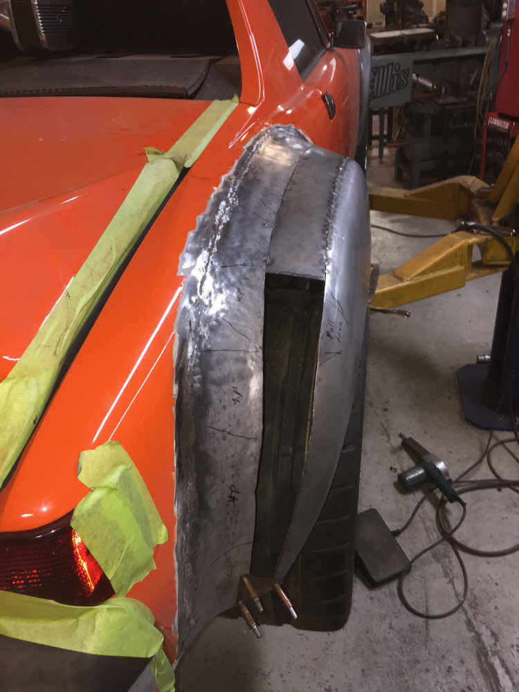
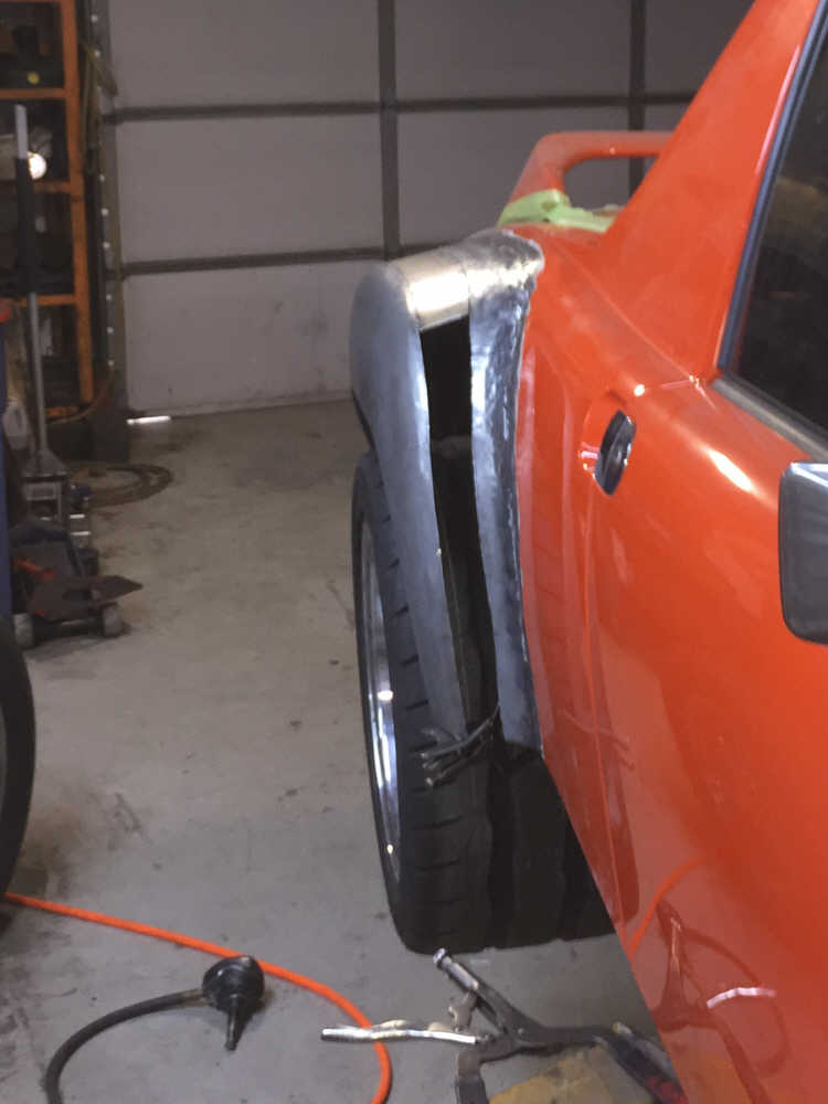
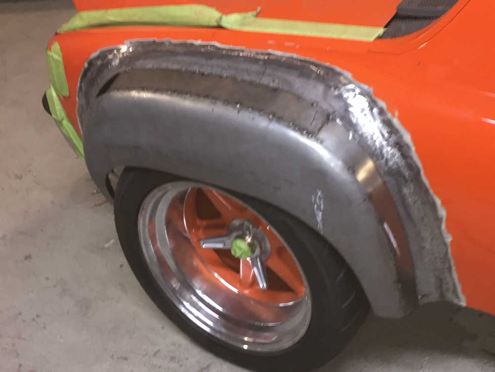
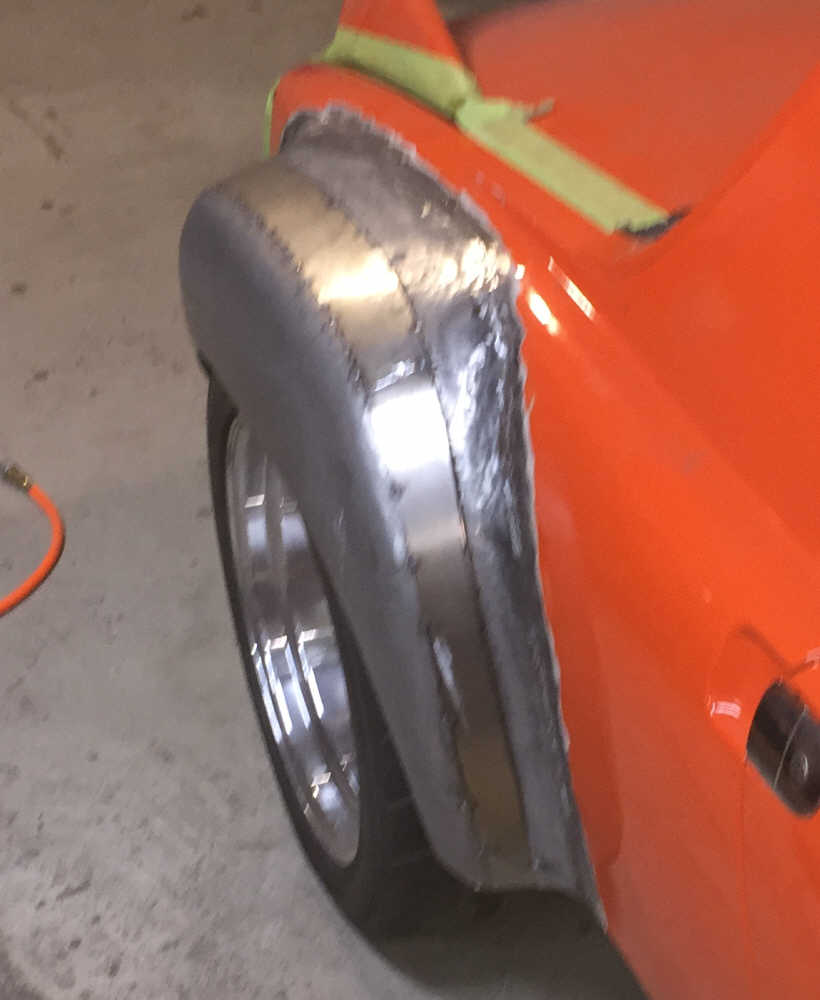
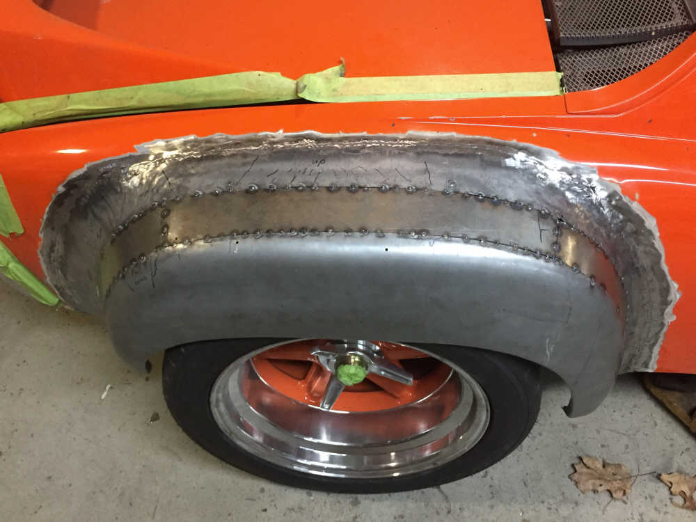
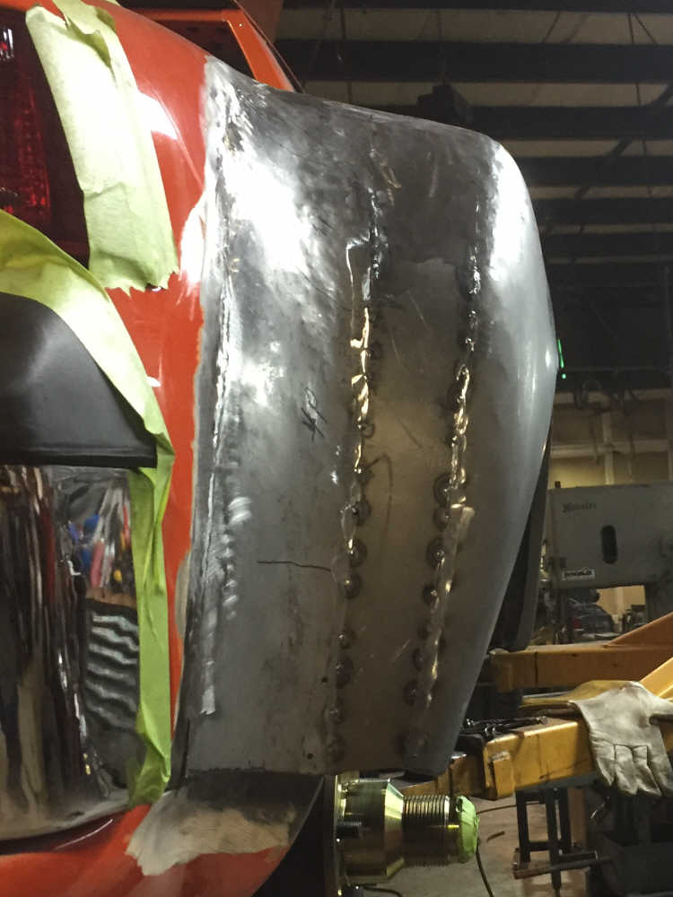
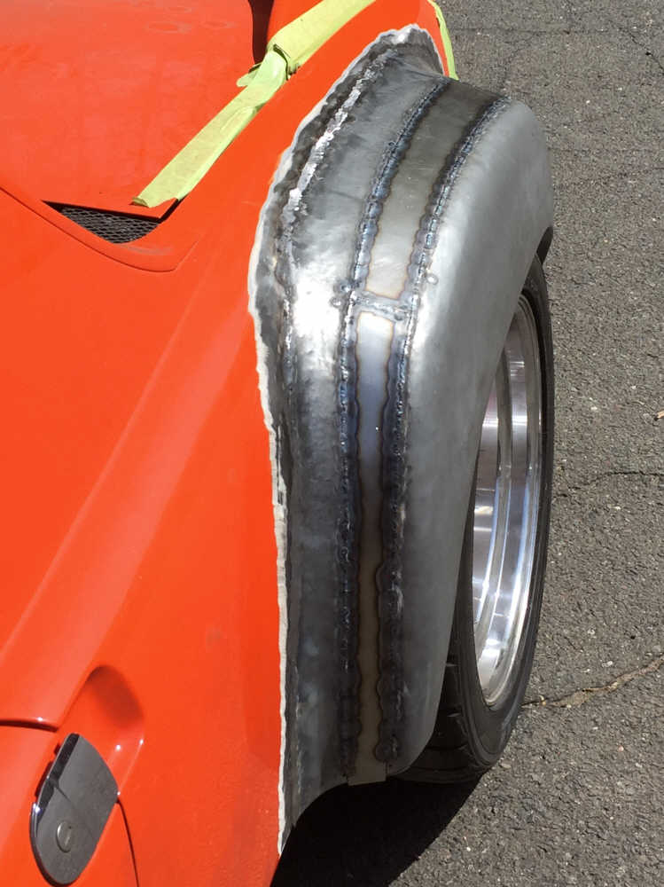
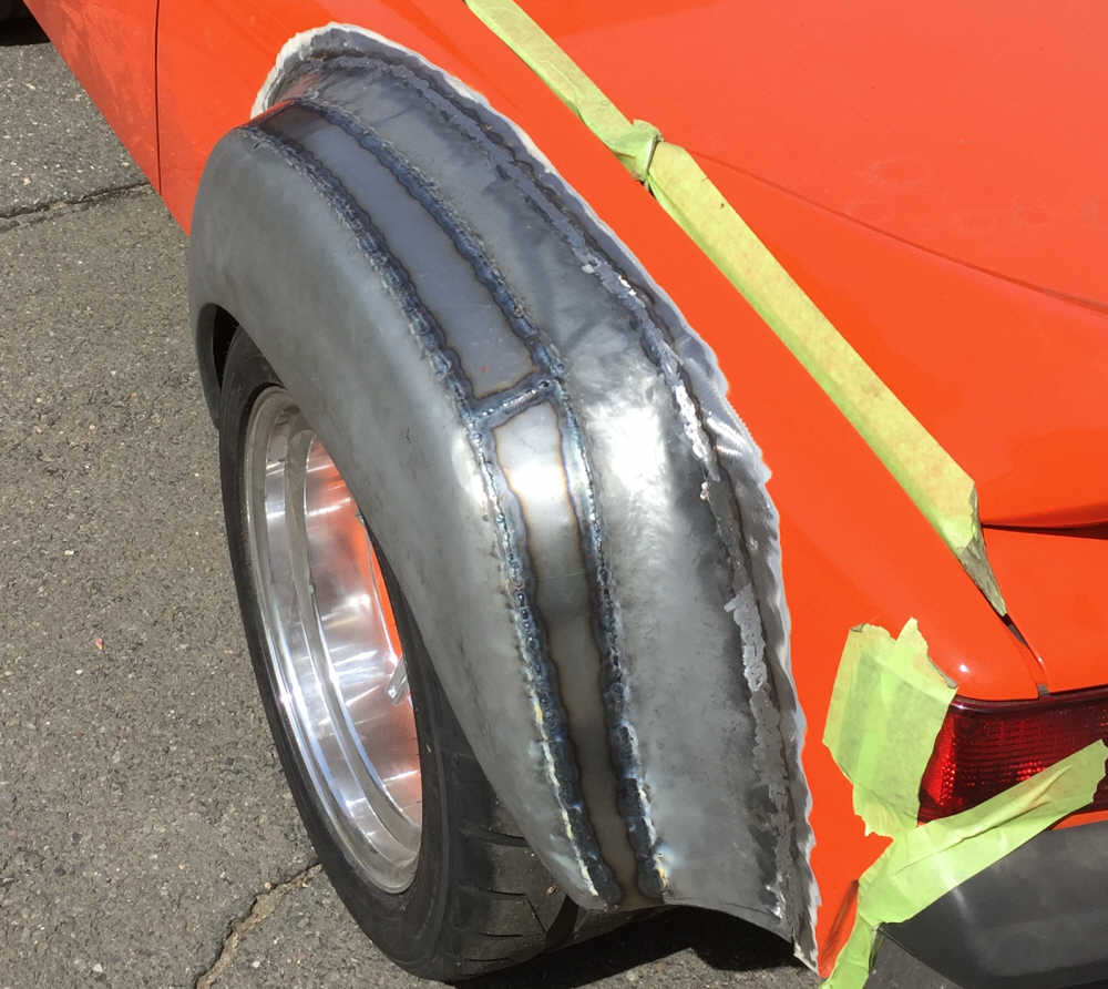
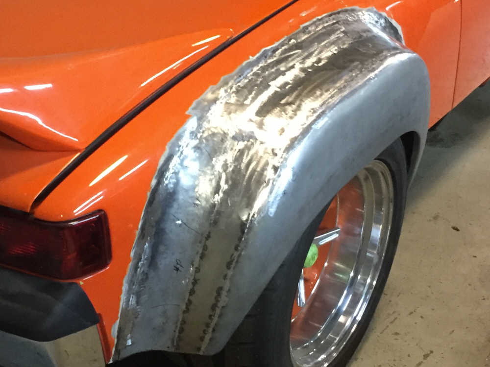
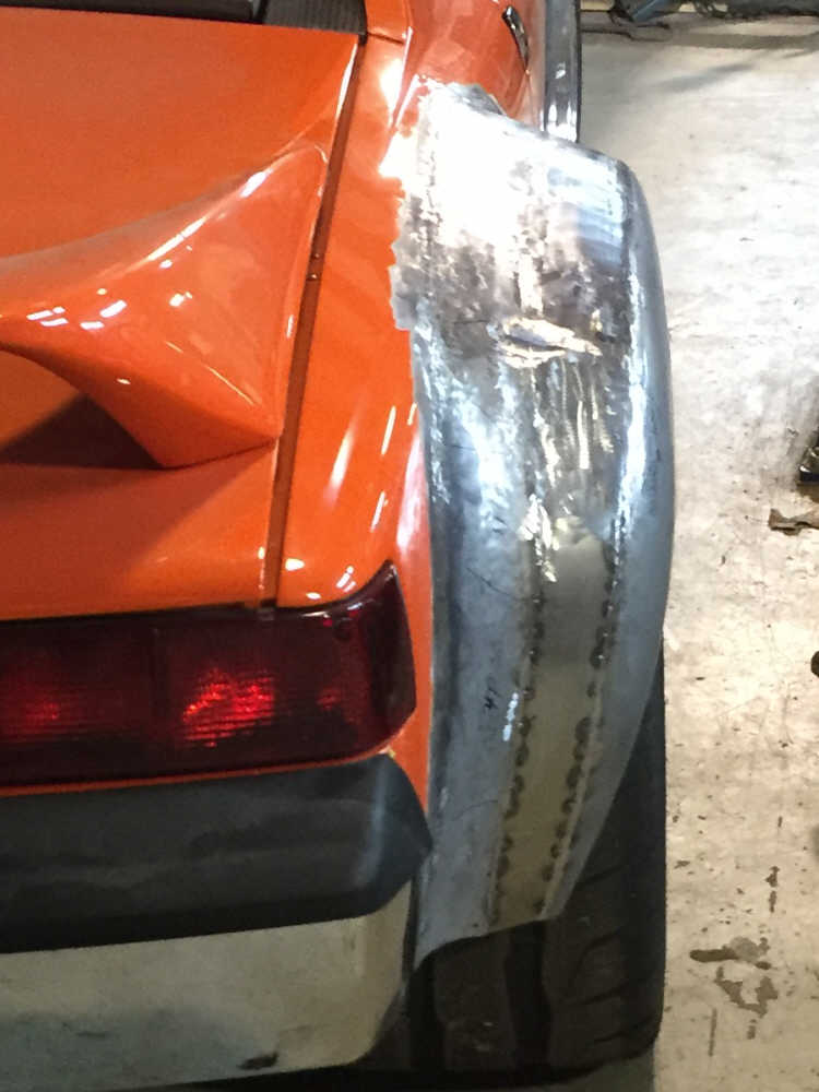
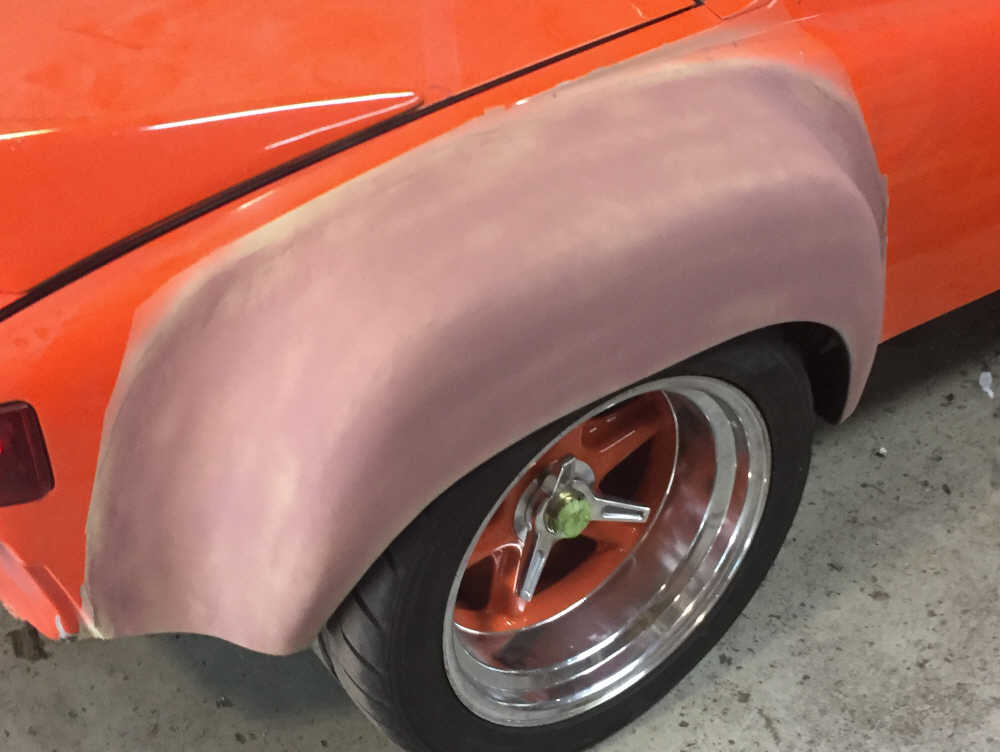
Posted by: Curbandgutter Aug 25 2018, 05:31 PM
Thank you @http://www.914world.com/bbs2/index.php?showuser=209 this is super helpful
Posted by: Curbandgutter Aug 29 2018, 12:23 PM
Well I started to install the flares. I started with it upside down cause it makes it so much easier. I painted both mating surfaces with weld-thru-primer before welding. Notice the rear fender how it encroaches onto the rear tail light. That is because I stretched the wheel base 3". I like the way it is fitting. I will need to add about 6" to the rear flare and 5" to the front flare. I'm waiting for the new rims to come it before I do that though.
Attached thumbnail(s)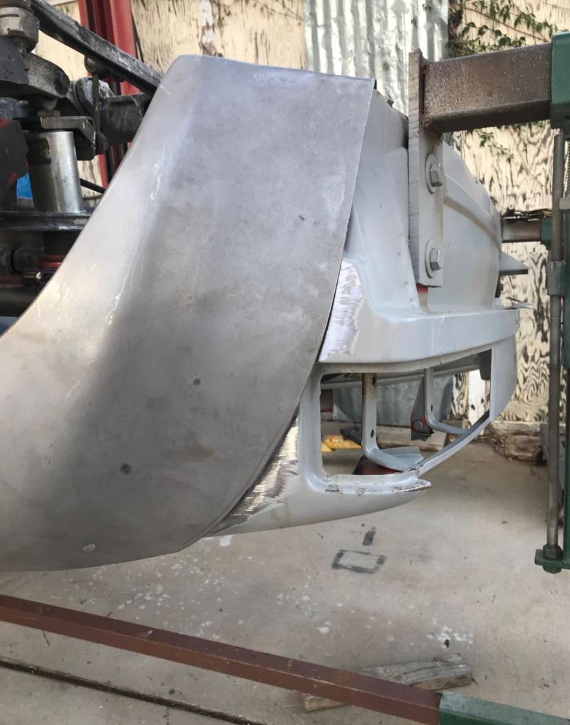
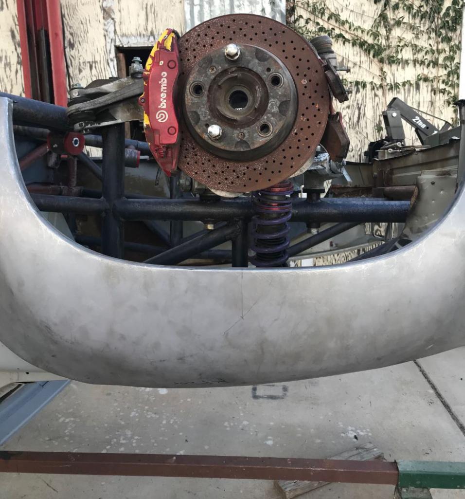
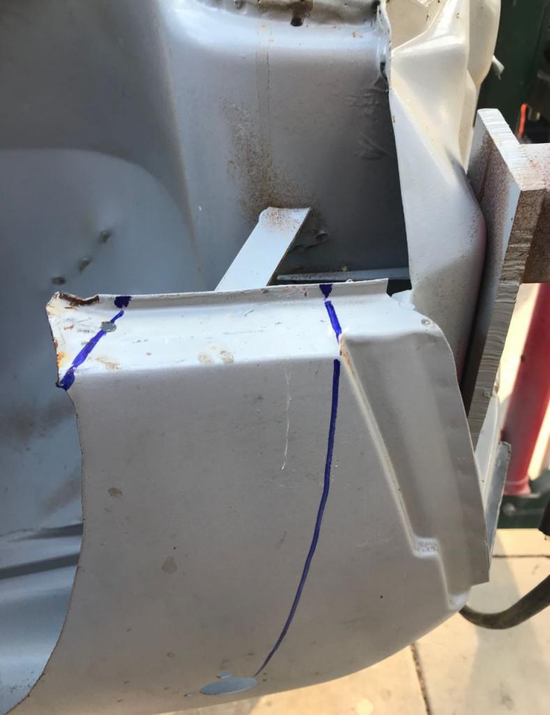
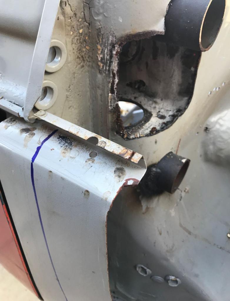
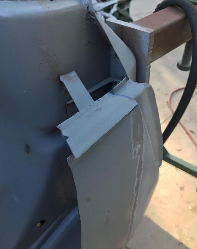

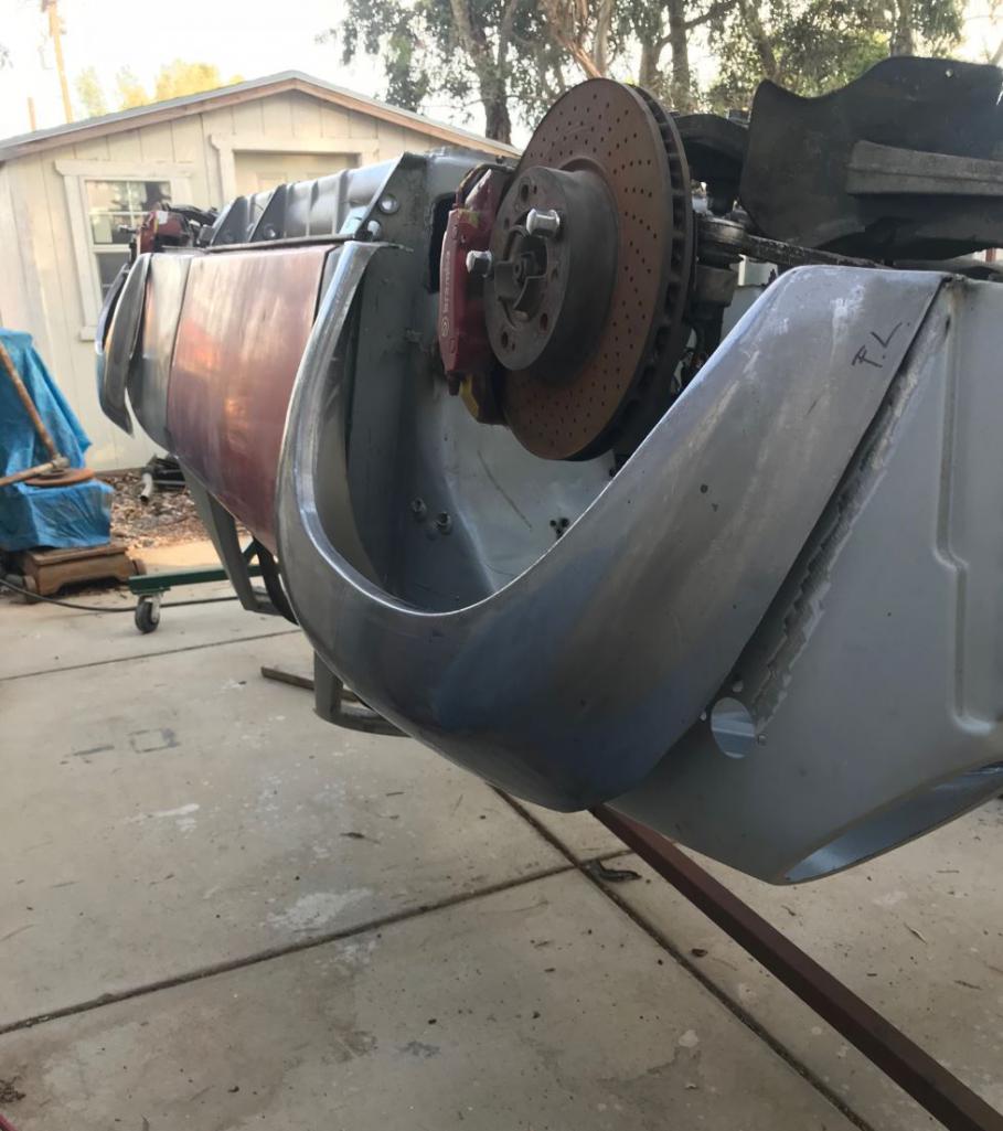
Posted by: ValcoOscar Aug 29 2018, 12:51 PM
Wow Rudy...
That's Bad Ass. 
For those who don't know the meaning.
https://www.youtube.com/watch?v=RAGcDi0DRtU
Enjoy !!!
Oscar
Posted by: Andyrew Aug 29 2018, 01:08 PM
Im jealous of the fun metal fab work your going to do
However only 1 fender would be fun, 4 would be repetitious and boring 
6" extension of those flares is going to be substantial!!!
Posted by: 914Toy Aug 29 2018, 03:05 PM
Wow Rudy...
That's Bad Ass.
For those who don't know the meaning.
https://www.youtube.com/watch?v=RAGcDi0DRtU
Enjoy !!!
Oscar
I did enjoy
Posted by: Curbandgutter Aug 29 2018, 03:20 PM
Im jealous of the fun metal fab work your going to do
However only 1 fender would be fun, 4 would be repetitious and boring
6" extension of those flares is going to be substantial!!!
Andy I hear you on that. The reason it's 6" is that the 996 hub to hub dimension is 5" wider than a 914. So, add to that the 335 tire on 12.5" rims and there are the ingredients for the wide rear. I think that it wont look too weird since I am adding an 18" wide radiator on each side within the quarter panel that will be taper to the interior about 12" from the face of the quarter panel. If I did not have that I would of put in some serious + offset on the 3-piece rim and tuck the meats inside. But I don't like the look of the meats tucked in. Yes there will be more aerodynamic drag on them....but I don't care, it will look downright mean.
Posted by: Andyrew Aug 29 2018, 04:07 PM
You might need a third cooler FYI. That 2.7 runs pretty hot. I would run an electric water pump so you can at least have as optimal cooling as possible
And your cars going to be awesome I just love everything about this build!
Posted by: worn Aug 29 2018, 05:29 PM
Wow Rudy...
That's Bad Ass.
For those who don't know the meaning.
https://www.youtube.com/watch?v=RAGcDi0DRtU
Enjoy !!!
Oscar
I am descended from Finns and now I am removed rom the thread pondering ass, or asses. Still, it looks like things are in good hands.
Posted by: Curbandgutter Aug 29 2018, 09:17 PM
Wow Rudy...
That's Bad Ass.
For those who don't know the meaning.
https://www.youtube.com/watch?v=RAGcDi0DRtU
Enjoy !!!
Oscar
Amazing how complex that word can be.
Posted by: Curbandgutter Sep 2 2018, 11:40 AM
Hey guys I’m needing to borrow a sheet metal break for a couple of months. Does anyone have one that I can borrow or is someone willing to let theirs go on the cheap. Let me know.
Posted by: 76-914 Sep 2 2018, 11:58 AM
Hey guys I’m needing to borrow a sheet metal break for a couple of months. Does anyone have one that I can borrow or is someone willing to let theirs go on the cheap. Let me know.
I have a 24" or 30" brake. I forget which size it is.
CPOS but it works.
Posted by: Curbandgutter Sep 2 2018, 03:20 PM
Hey, guys, I’m needing to borrow a sheet metal break for a couple of months. Does anyone have one that I can borrow or is someone willing to let theirs go on the cheap? Let me know.
I have a 24" or 30" brake. I forget which size it is.
CPOS but it works. As long as the CPOS works.......
I'll call you later this weekend.Posted by: Curbandgutter Sep 4 2018, 09:32 AM
Wow...love these panel clamps.
Attached thumbnail(s)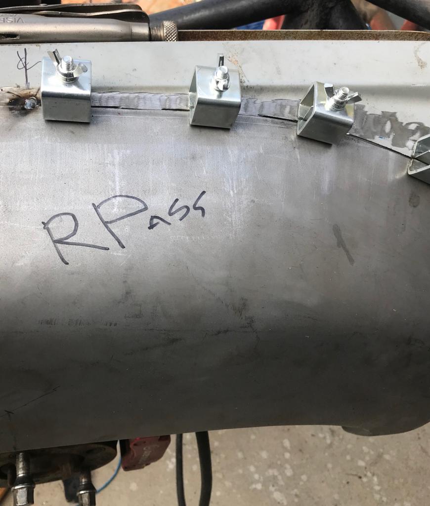
Posted by: Curbandgutter Sep 7 2018, 11:09 AM
Well I'm in the process of welding the fenders on. It takes me about 4 hours per fender. Here is how I did it.
First, flatten out the bottom lip of the existing fender. This is to give you a flat area with which to attach the new fender. At this time also cut the existing fender along the bottom edge.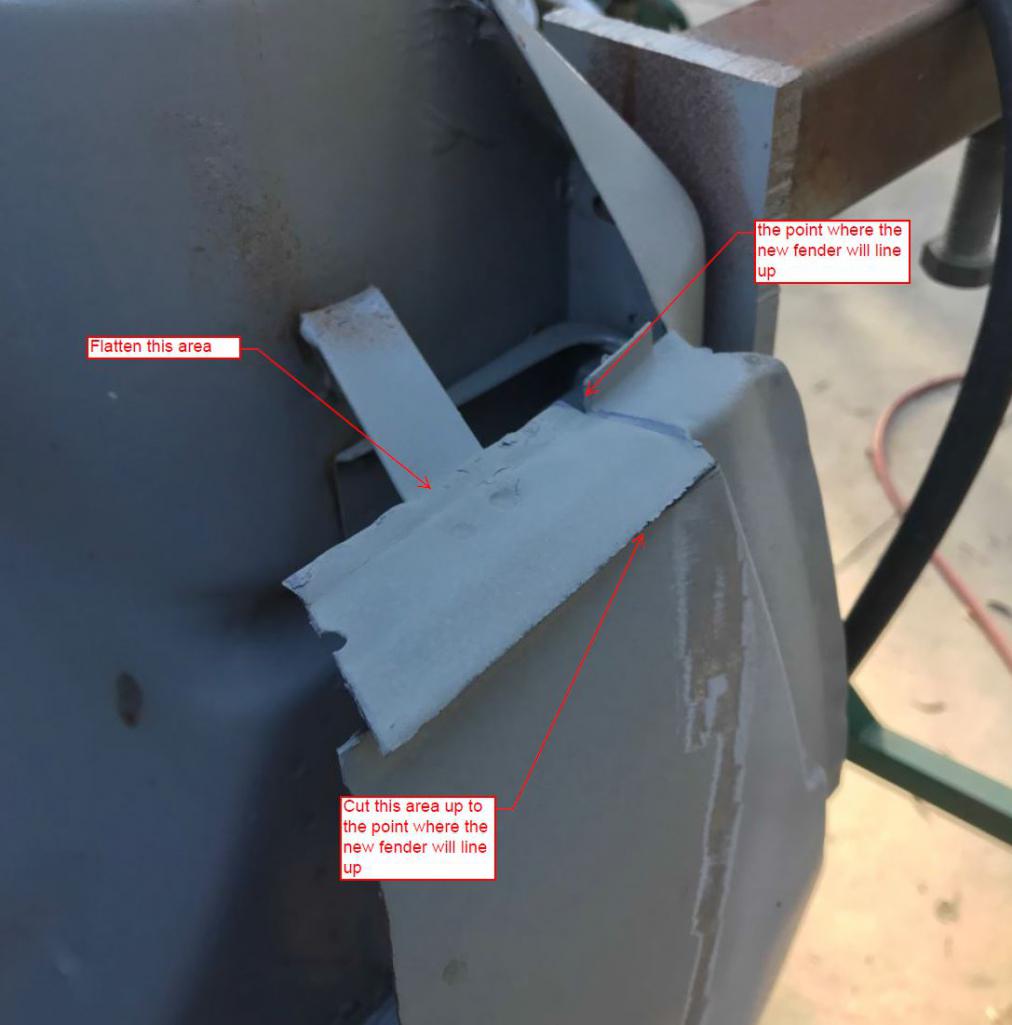
Then attach the fender to the two bottom lips and weld. Then tack weld along the top center of the fender. This will give you 3 points where it is attached to the car now.
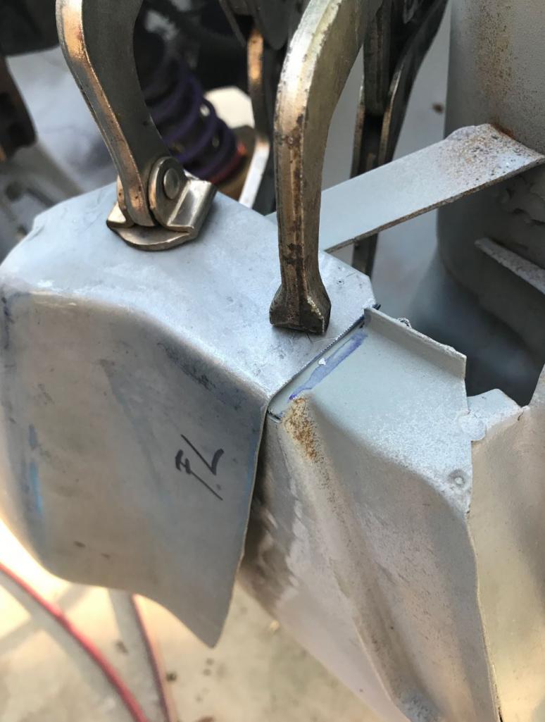
Then cut from the bottom to the top half of the fender an attach panel clamps. I found that using a thin cut off wheel worked the best. It gave a nice gap to weld and was not so tight that it would bind the panel clamps when trying to pull out.
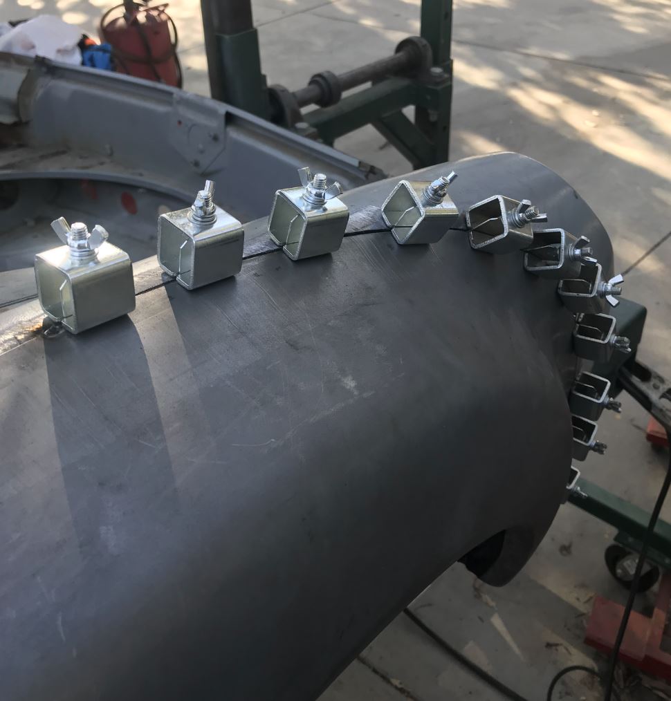
Spot weld in between the clamps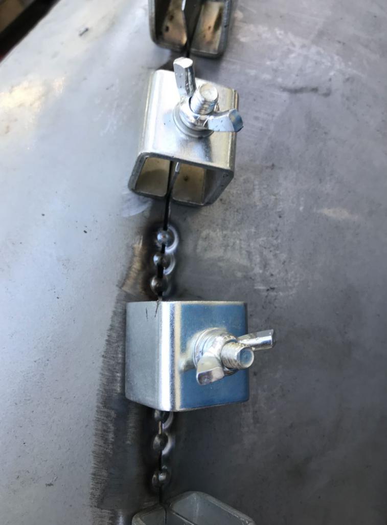
Then remove and spot weld remaining gaps that the clamps left behind.
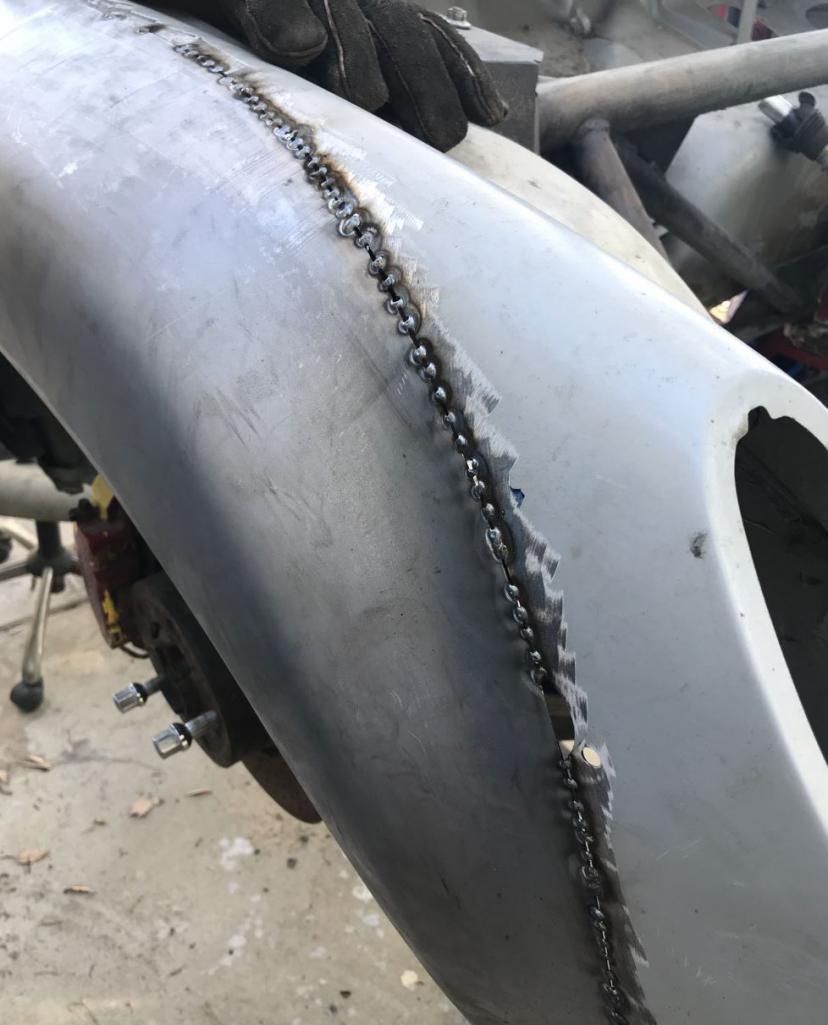
Cut and clamp the other half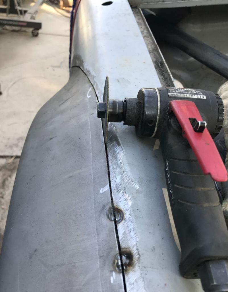
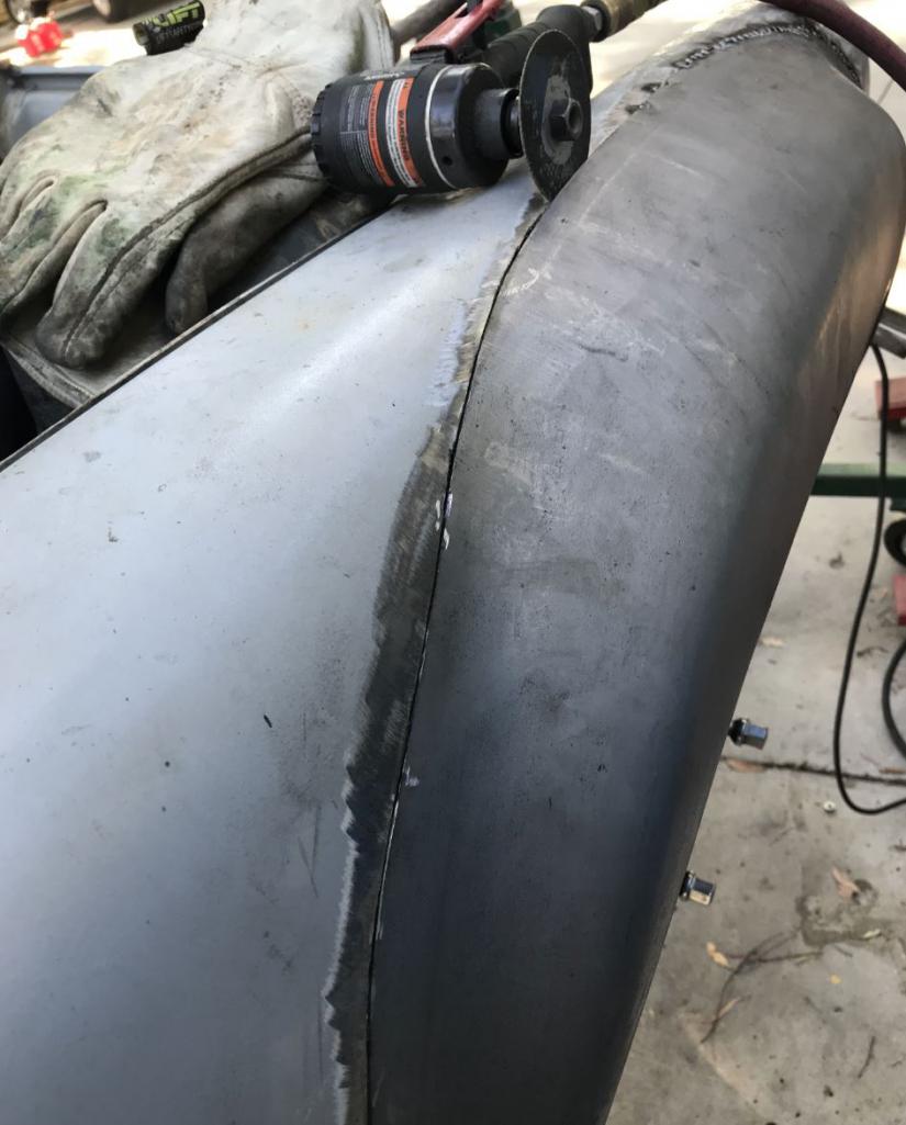
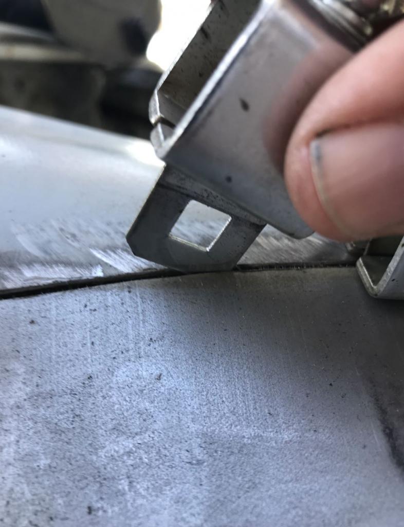
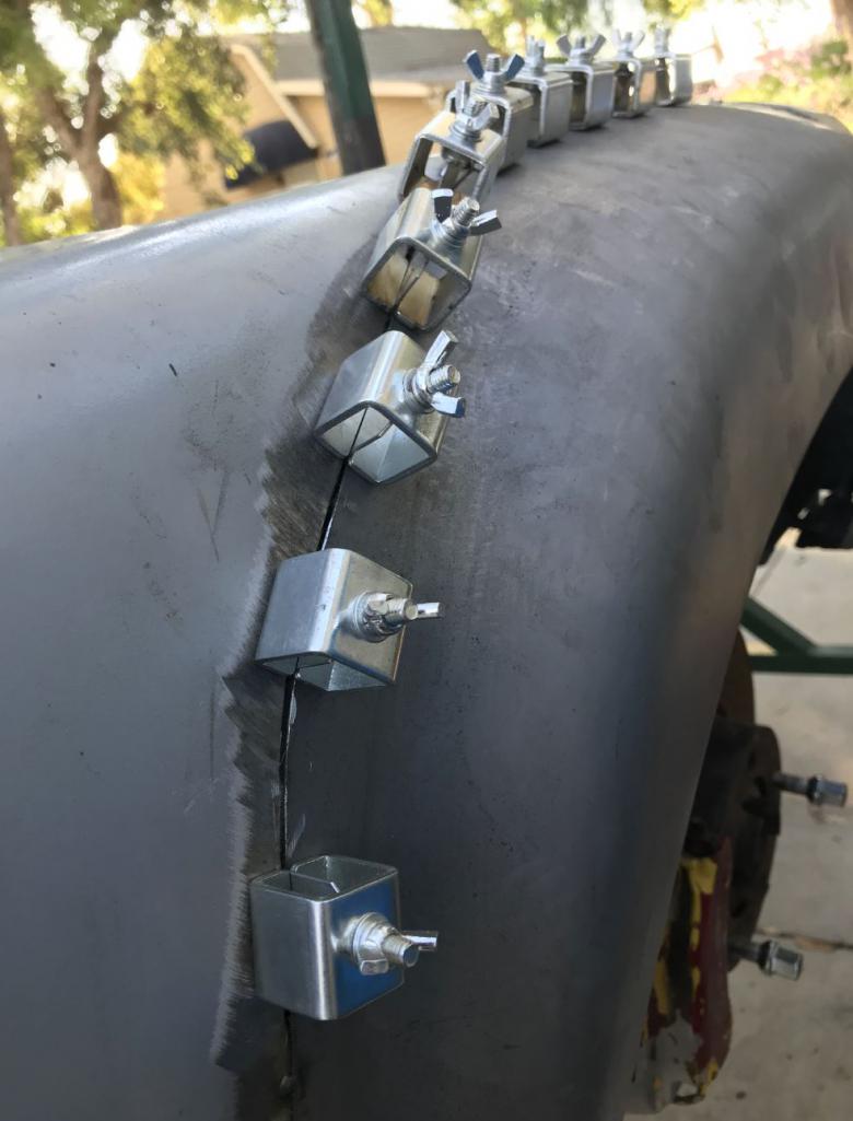
Weld, remove clamps, weld, and grind. I find that it was super easy to grind with the cut-off wheel and then to finish with an 80 grit disk sander.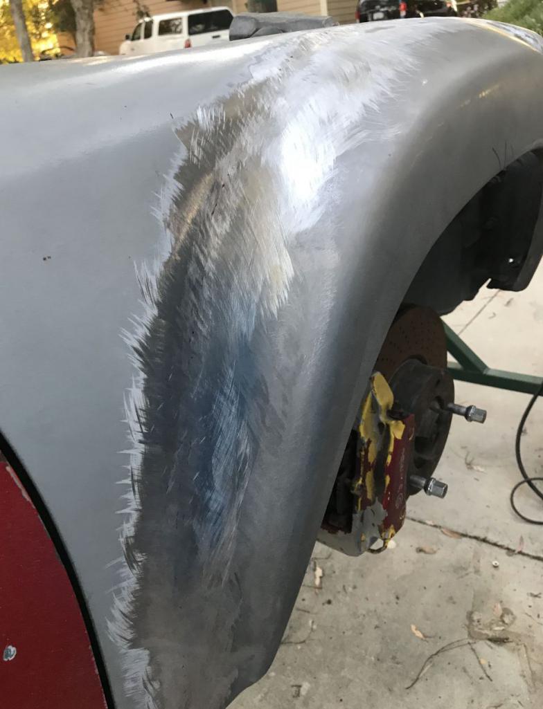
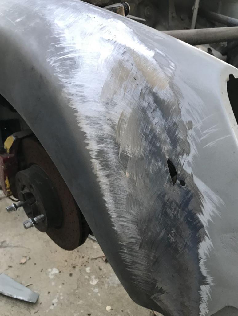
Posted by: ValcoOscar Sep 7 2018, 11:59 AM
Amazing...
Pictures speak volumes thanks Rudy
Gee..I need more time off work
See you tomorrow for breakfast!!!
Oscar
Posted by: tygaboy Sep 7 2018, 12:13 PM
Rudy - I know! You can come up to Petaluma and we can install my flares!
Seriously, that looks GREAT! Nice job!
Posted by: Andyrew Sep 7 2018, 02:07 PM
Wow!!! Fantastic work Rudy!
Posted by: Maltese Falcon Sep 7 2018, 08:39 PM
The gap-police would give you a 100% + on your continuity
Posted by: 914forme Sep 7 2018, 09:52 PM
I think you could rent yourself out to install flares
1/8" cut off wheel? Who's wheels are you using the last set of thins I got destructed every time they spun up, after two of them launched across the room, I grew the tossed them away. Seen to many pictures of what can happen.
Posted by: 76-914 Sep 9 2018, 10:03 AM
I dropped off my bumpers to Oscar and had breakfast w/ Rudy and him yesterday. I felt like I was in the presence of Royalty as I sat with these 2 metal-meister's. Afterwards I stopped by Rudy's to check his progress and snapped a couple of pic's. Very impressive build.Rudy took the time to walk me thru the flare install. He said it was easy peasy but me thinks it's a trap. Seriously, he made it look simple but I know better. Anyway, here are a couple of shots of Rudy's project.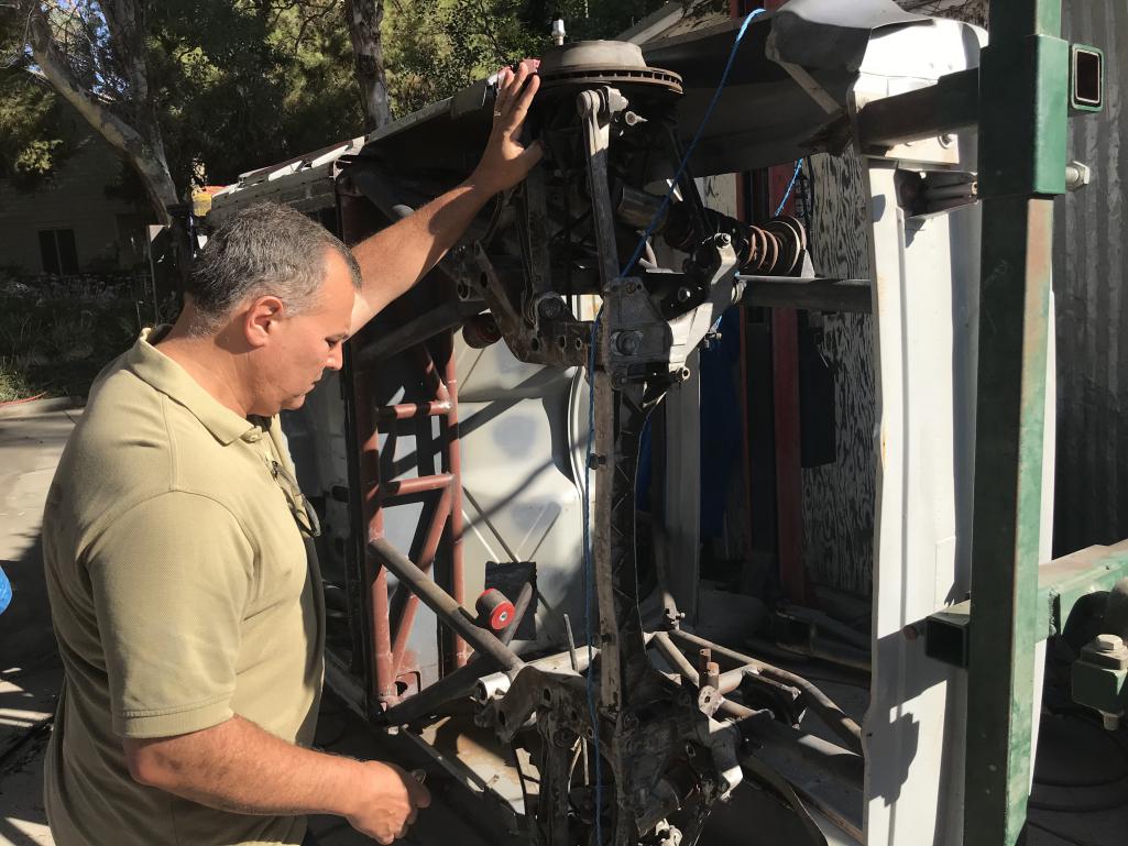
Posted by: 76-914 Sep 9 2018, 10:04 AM
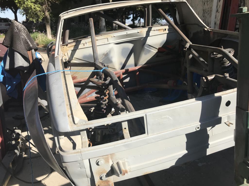
Posted by: 76-914 Sep 9 2018, 10:04 AM
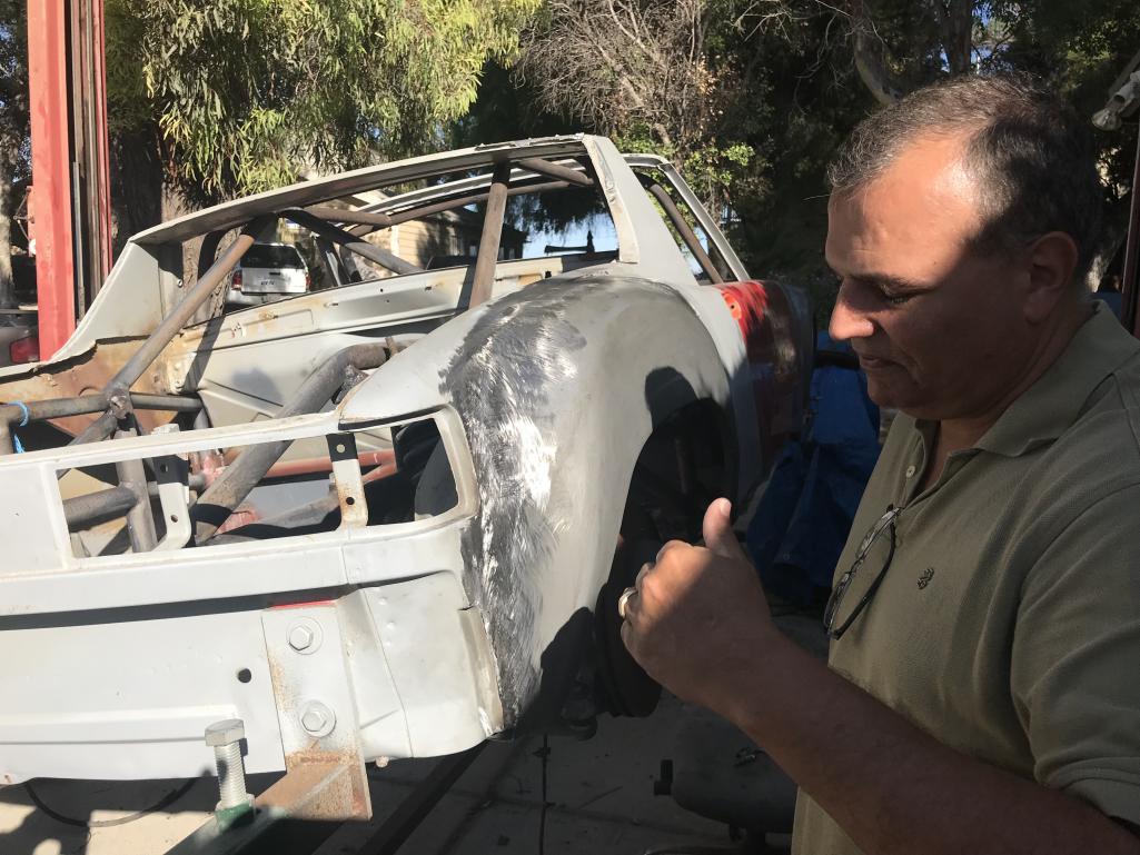
Posted by: Curbandgutter Sep 10 2018, 10:49 AM
Hey Guys , @http://www.914world.com/bbs2/index.php?showuser=16669 @http://www.914world.com/bbs2/index.php?showuser=19241 @http://www.914world.com/bbs2/index.php?showuser=172 @http://www.914world.com/bbs2/index.php?showuser=2755 @http://www.914world.com/bbs2/index.php?showuser=2388 @http://www.914world.com/bbs2/index.php?showuser=9964 thank you for the compliments they really do help with morale.....encouragement helps fuel the project.
Those butt clamps were amazing, and cutting it with the thin 1/32" cut -off while using the fender as the scribe line was the trick. Also doing one half of the fender at one time was very helpful. I used 0.23 welding wire and a 110-volt Lincoln. It worked perfectly! My 200 amp wire welder was too big and it didn't like to push 0.023 wire 15' in the gun. I didn't want to tig cause I'm not good with Tig.
Well I completed the 3 fenders and the last fender is all tacked in. It now needs final welding and grinding. It will take about 30 minutes to complete. Then it's off to the floor and finish the openings in the chassis.
As for the cut-off wheel I didn't know it, but I stumbled onto some super good wheels. I was cutting along no problems and then ran out and got another brand since my local welding store ran out of the ones I was using. So I bought this other set which was expensive and was surprisingly, "made in the USA", but was pure crap. It lasted 12" of cutting into the fender before wasting away. You could watch it reduce in size in real time......ridiculous. And then, dust everywhere. The original ones would last about 12'....feet not inches. So the EXCELLENT cut off was by Pearl and it was a 1/32" thick wheel. It lasts for one fender if you include grinding. However, I think that if I did not grind with it that it could cut all four fenders.....it's that good.
Here is the Excellent wheel that I used.
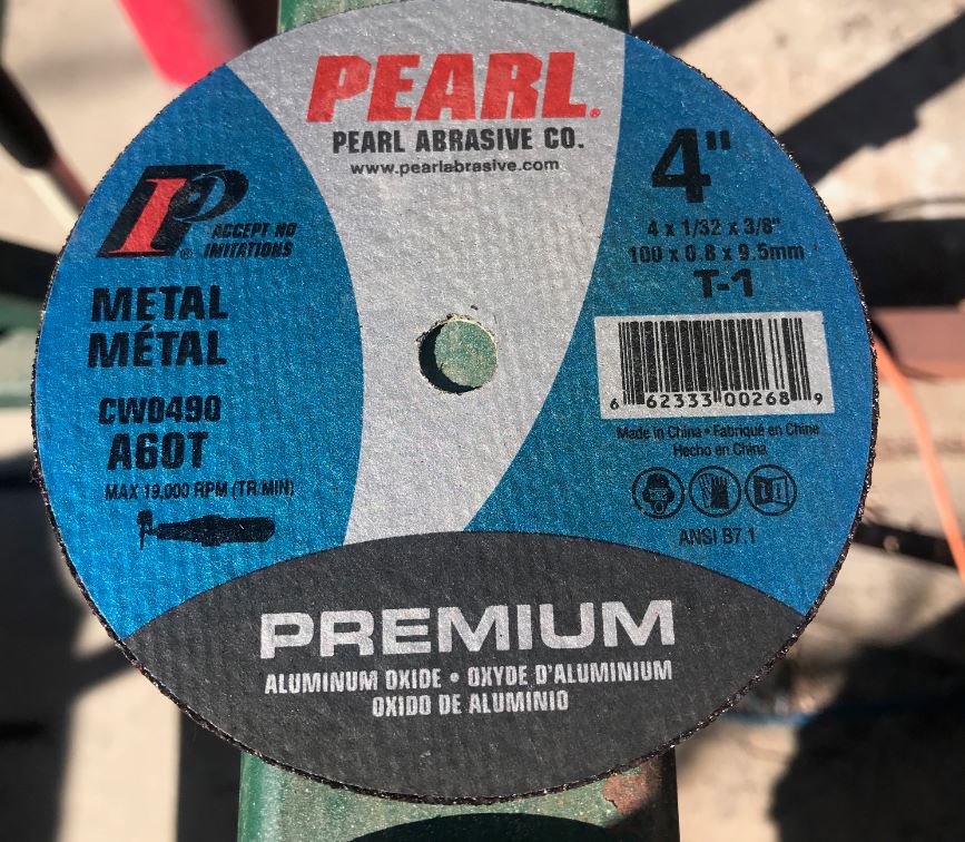
Here is the crap one.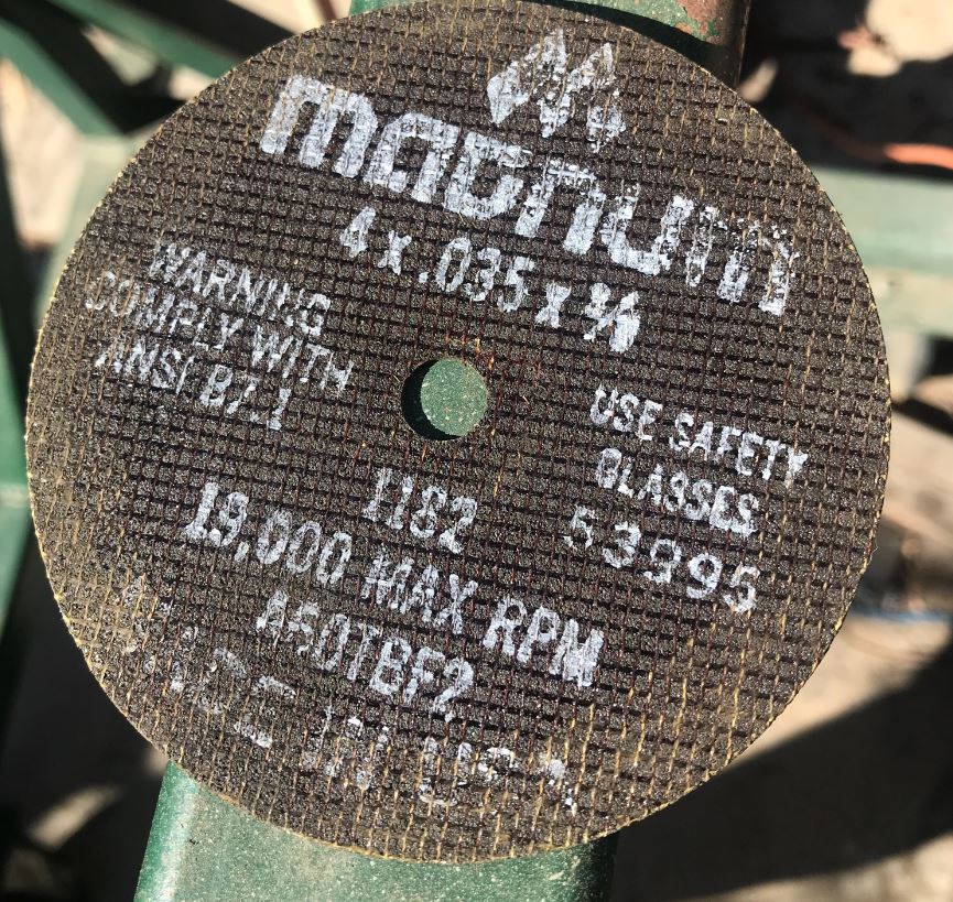
Left Front Fender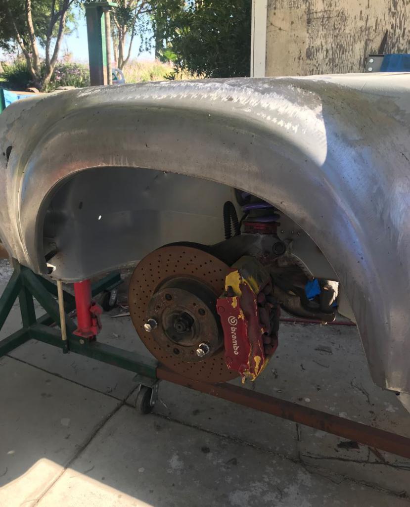
Left Rear Fender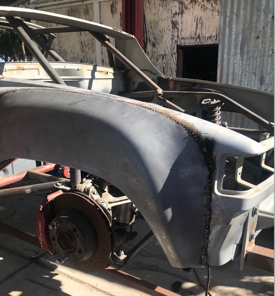
Posted by: Andyrew Sep 10 2018, 11:44 AM
I love 1/32" cutting wheels! Like butter! I'll have to get these, as I always just grab a set at harbor freight...
Posted by: Rand Sep 10 2018, 12:02 PM
This reminded me of another epic thread about flare method by Dan Root. Can't find it right now, but maybe someone has a link?
Posted by: Curbandgutter Sep 10 2018, 07:07 PM
This reminded me of another epic thread about flare method by Dan Root. Can't find it right now, but maybe someone has a link?
@http://www.914world.com/bbs2/index.php?showuser=3573 here it is http://www.914world.com/bbs2/index.php?showtopic=89850
Posted by: 914forme Sep 10 2018, 07:44 PM
@http://www.914world.com/bbs2/index.php?showuser=15637 Rudy thanks!
Posted by: FourBlades Sep 10 2018, 08:42 PM
Such a great thread and project.
I looked away for a while and some really cool projects have come along.
Keep it coming.
John
Posted by: Cracker Sep 11 2018, 07:09 AM
Great to see this project back on track...looking great Rudy! 335?!?! Holy moly pal!
Cracker
Posted by: Curbandgutter Sep 12 2018, 11:42 AM
Great to see this project back on track...looking great Rudy! 335?!?! Holy moly pal!
Cracker
Yep, my car is too light and I need mechanical grip.
Here is a picture of the wheel and tire combo that I ordered. It will take 8-10 weeks.
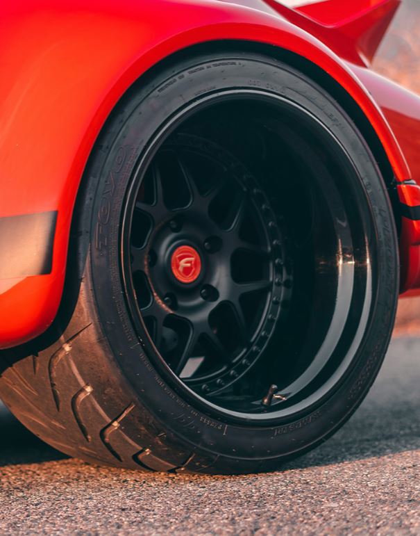
Except that the lip will be polished like this.
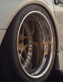
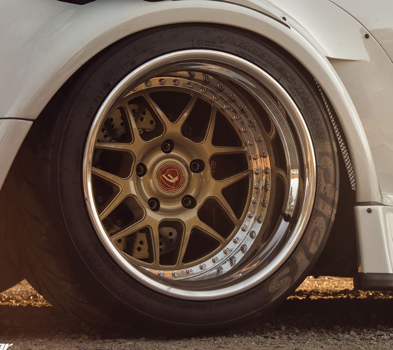
Posted by: Cracker Sep 12 2018, 01:45 PM
Very cool Rudy! Here is my (small) 275 rear next to the gt40's 415...it would've been waaaaay to big!
Cracker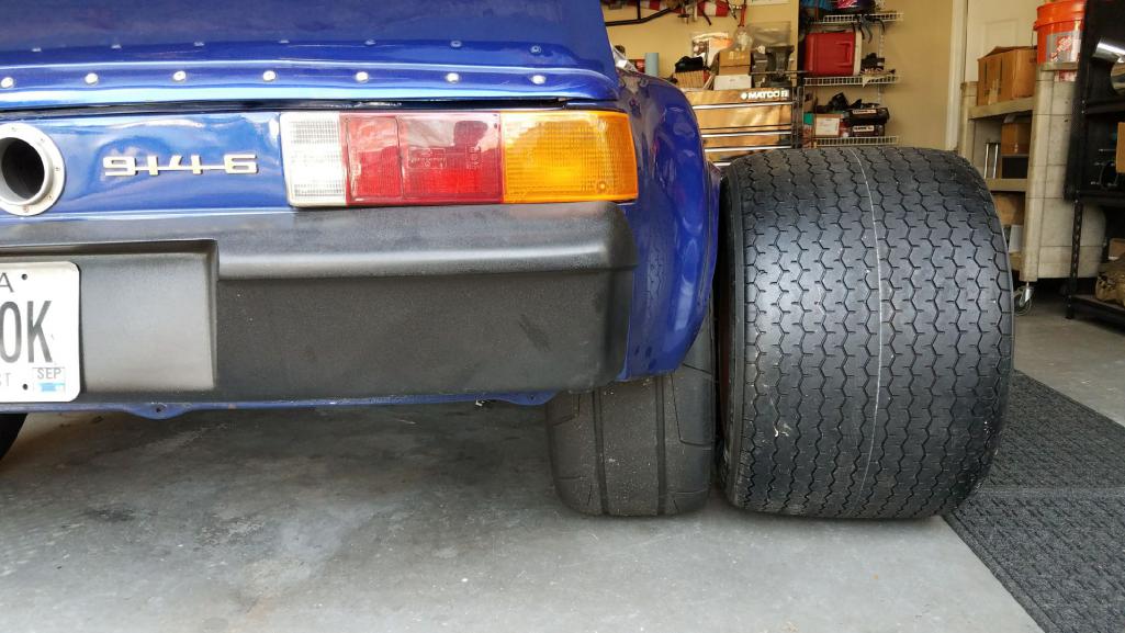
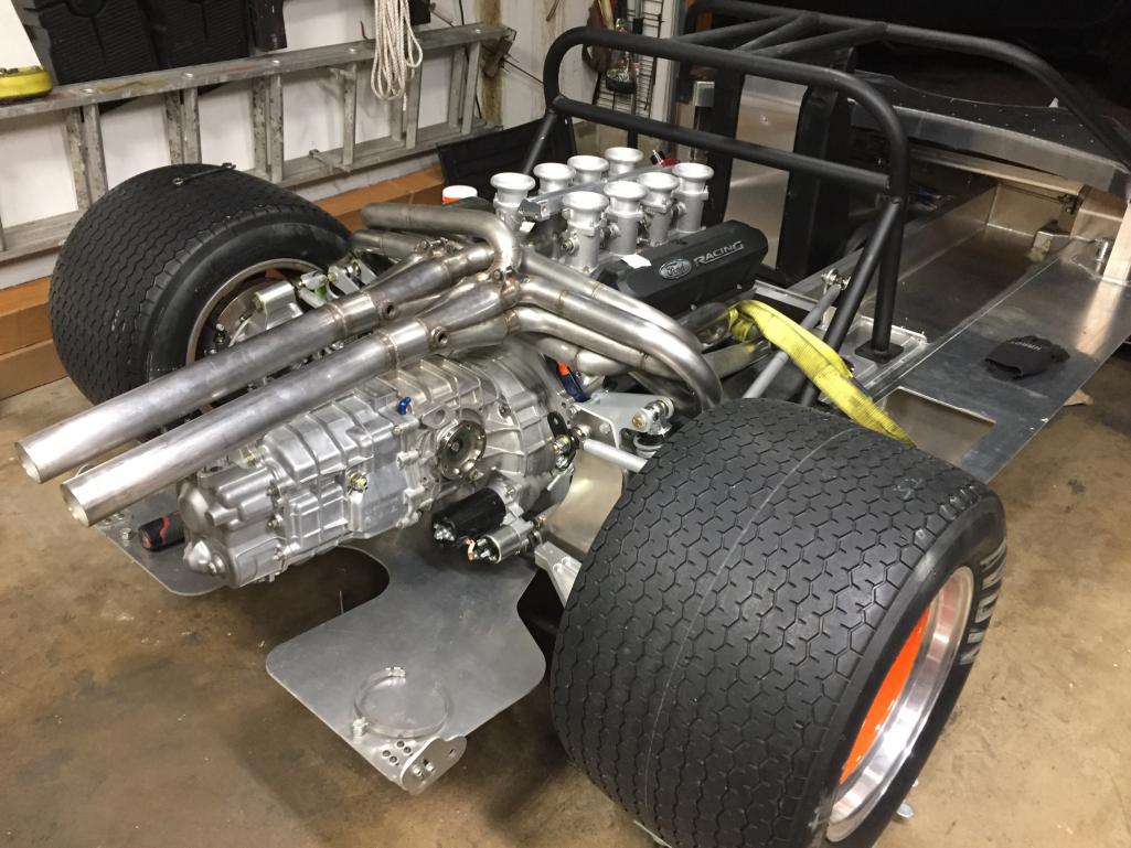
Posted by: Curbandgutter Sep 17 2018, 03:46 PM
Very cool Rudy! Here is my (small) 275 rear next to the gt40's 415...it would've been waaaaay to big!
Cracker
Cracker you crack me up.:
You had to throw that 415 up there huh
. It's like "oh yeah, you got 335's.........look at these 415's" All kidding aside that is an amazing ride there though. Love those 180 degree headers and the ITB's on that V8...stunning.
Maybe you can do this to your 914??
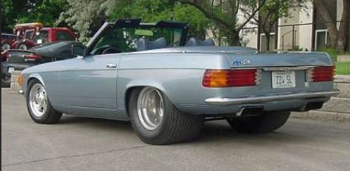
Posted by: Curbandgutter Oct 15 2018, 02:27 PM
Update pictures of center tunnel and floor. Ill be finished with the center tunnel this weekend and will start with new floor. I decided on making my own floor so we will see how it turns out. I still need to add the web struts at each end of the center tunnel and it will be complete and fully structural. I plan on doing twist test soon and will be testing it with an without the top bar that tie both the rear roll bar hoop and the front roll bar hoop. If the twist test shows 1 or 2% stiffness improvement....then they will be removed.
Attached thumbnail(s)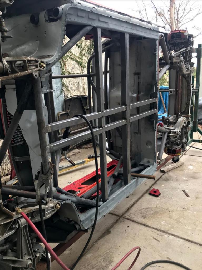
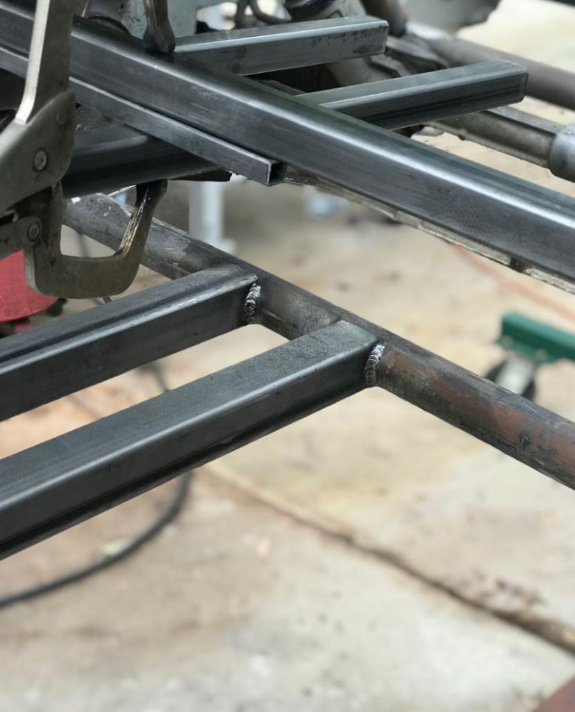
Attached image(s)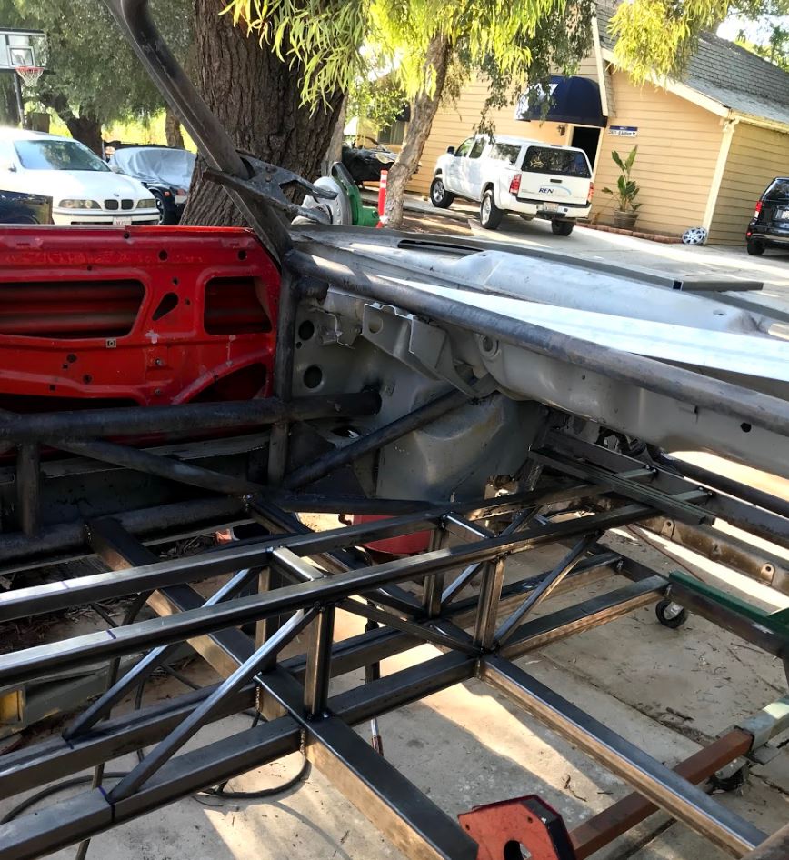
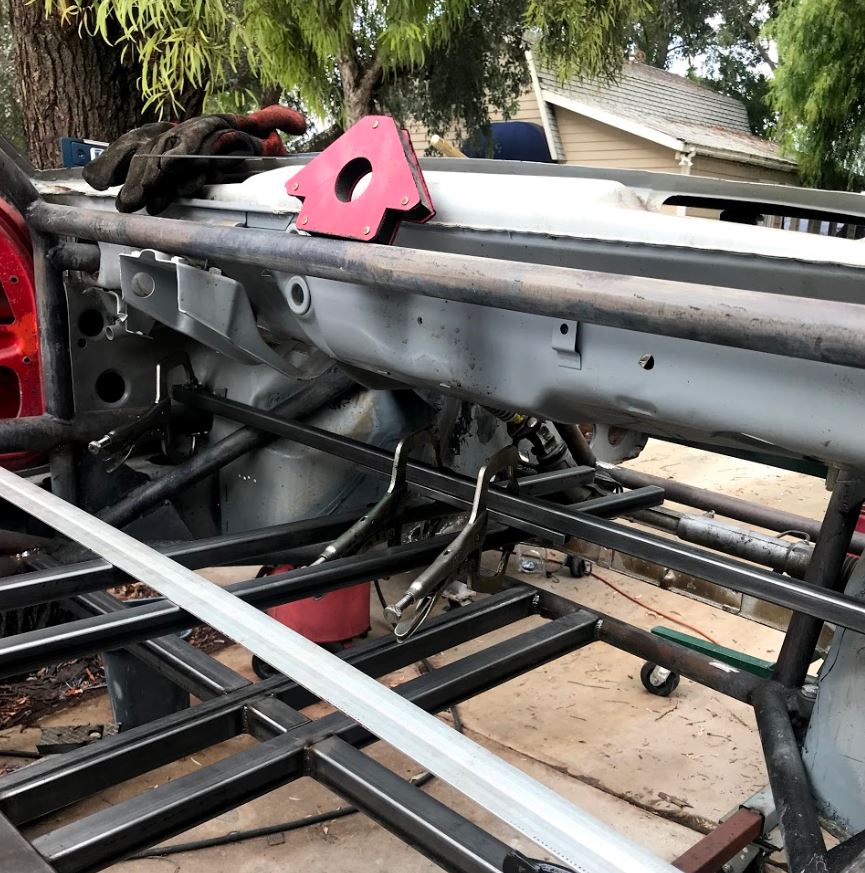
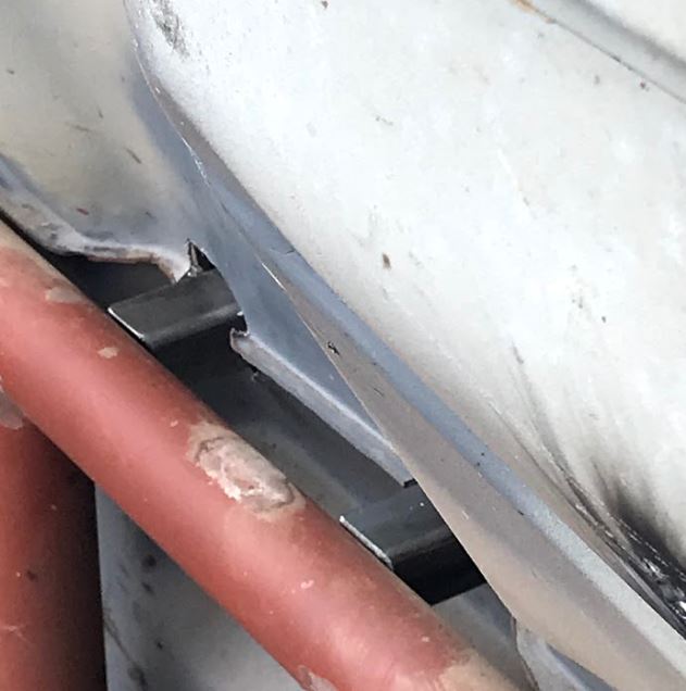
Posted by: Cracker Oct 15 2018, 04:00 PM
Looks great Rudy...is it going to weigh less than 3k pounds? BIG & BEEFY all the way!
Tony
Posted by: Curbandgutter Oct 15 2018, 04:33 PM
Looks great Rudy...is it going to weigh less than 3k pounds? BIG & BEEFY all the way!
Tony
Hey Tony... I sure hope it will come in less than 3K #. I do believe that it will be slightly heavier than a stock 914-6. I'm counting on some composites on the body to help offset the weight.
Posted by: dr.tim Oct 15 2018, 04:44 PM
BIG & BEEFY all the way!
I was thinking the same thing. What size / thickness tube are you using?
Posted by: Cracker Oct 15 2018, 06:17 PM
It was said in jest...t will be well under the 3K# number.
Tony
Posted by: seanery Oct 15 2018, 07:45 PM
Wow, this is great! Just read it start to current! Love it!! =)
Posted by: Curbandgutter Oct 21 2018, 05:08 PM
All right now....I finished with the center tunnel. ADDED WEIGHT TRIGGER ALERT Never mind that it is accounted for and offset with carbon fiber. Next step is the floor. I am getting the Eastwood 28 inch hand beader. Hovwever, I have a motor that I am going to adapt. Then I am am going to add so much beading that it will make us all sick and I'll have to scrap it and do a more "normal" look. Also, I've decided on using inboard suspension on the rear and on the mac pherson strut front suspension. I want the ability to make the shocks to travel more than the wheel and I want the ability to create a rising rate motion with a linear spring. Any input on that is appreciated.
Attached thumbnail(s)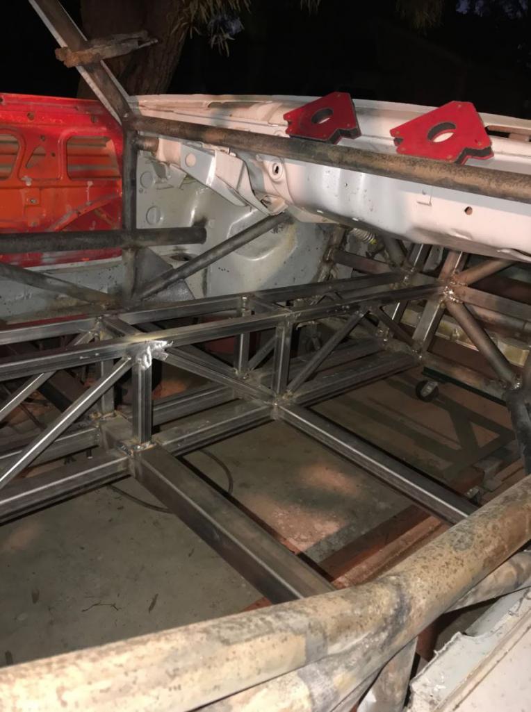
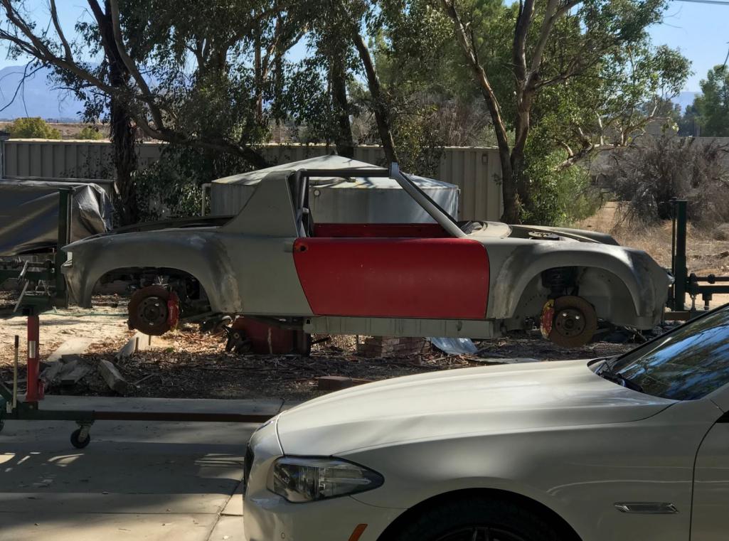
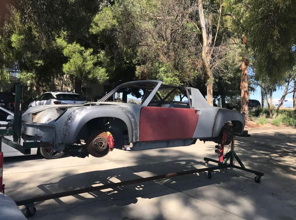
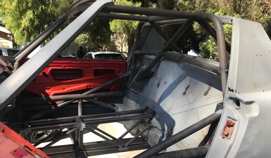
Posted by: tygaboy Oct 21 2018, 05:27 PM
Looking great, Rudy!
Not sure what you're plans are for plumbing but a heads up on a lesson learned from my console:
If you're planning to run hard lines, make sure you have a way to get them in/out of the chassis, once the console is in place.
I'm likely going to have to slice up my console so they can be installed and/or removed/replaced for any reason.
Oops.
Posted by: mgp4591 Oct 21 2018, 05:43 PM
Looking great, Rudy!
Not sure what you're plans are for plumbing but a heads up on a lesson learned from my console:
If you're planning to run hard lines, make sure you have a way to get them in/out of the chassis, once the console is in place.
I'm likely going to have to slice up my console so they can be installed and/or removed/replaced for any reason.
Oops.
Chris, did you run hard lines down the center, and if you did is there any thermal advantage over the hose option? Mine are run down the center as well and fishing them out is pretty straightforward.... I try to expect repairs like that so I've isolated my hoses and fuel lines so if there were any leaks, they just pour out of either end and not in the passenger compartment. I'd think hoses would be a better thermal isolator over a hard line even though they're not as pretty.... and your work is really good looking!
Posted by: Curbandgutter Oct 21 2018, 06:49 PM
Looking great, Rudy!
Not sure what you're plans are for plumbing but a heads up on a lesson learned from my console:
If you're planning to run hard lines, make sure you have a way to get them in/out of the chassis, once the console is in place.
I'm likely going to have to slice up my console so they can be installed and/or removed/replaced for any reason.
Oops.
Thanks for heads up. I’m thinking of pushing the fuel and hydraulics and maybe ac in the tunnel. Im thinking that the water will be pushed in the rocker panels. We will see.
Posted by: csdilligaf Oct 24 2018, 03:53 PM
Its coming along nicely Rudy. I'll have to stop by on my next trip up that way.
Posted by: Curbandgutter Nov 25 2018, 11:36 AM
Quick update, I finally finished welding the tube frame. My son is designing new lower 996 control arms to extend the front track 1" on each side for a total of 2". The control arm is getting a revised location for a strut to install inboard coilovers on the the mac pherson strut design. The mac pherson strut will be replaced with a sliding shaft and a monoball on a camber/caster plate. I think that this may be a first, not sure, but I haven't seen it on the web. While that is being machined by CSDILLIGAD out of a solid piece of 2026 aluminum on his HASS CNC mill, I will finish bead rolling a new floor. The 3-piece forged modular wheels were supposed to come in this week, keeping my fingers crossed maybe this week. BTW, I decided to convert the rear coilovers to inboard coil overs as well.
Question for the group, does anyone know the specs on the front ball joint for the 996 control arm? I need to source them for the new control arms. Any help would be appreciated. I'm looking for the length and taper and diamters. I'm hoping to find an off the shelf ball joint that I can press into the new control arm.
Posted by: Mueller Nov 25 2018, 12:03 PM
Quick update, I finally finished welding the tube frame. My son is designing new lower 996 control arms to extend the front track 1" on each side for a total of 2". The control arm is getting a revised location for a strut to install inboard coilovers on the the mac pherson strut design. The mac pherson strut will be replaced with a sliding shaft and a monoball on a camber/caster plate. I think that this may be a first, not sure, but I haven't seen it on the web. While that is being machined by CSDILLIGAD out of a solid piece of 2026 aluminum on his HASS CNC mill, I will finish bead rolling a new floor. The 3-piece forged modular wheels were supposed to come in this week, keeping my fingers crossed maybe this week. BTW, I decided to convert the rear coilovers to inboard coil overs as well.
Question for the group, does anyone know the specs on the front ball joint for the 996 control arm? I need to source them for the new control arms. Any help would be appreciated. I'm looking for the length and taper and diamters. I'm hoping to find an off the shelf ball joint that I can press into the new control arm.
I would check with Elephant Racing for the ball joint and look at their selection of 996 arms and components.
As for your strut idea, a Volvo owner beat you to it
(not mine, Sweden or Norway)
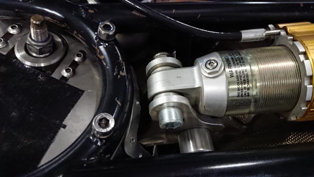
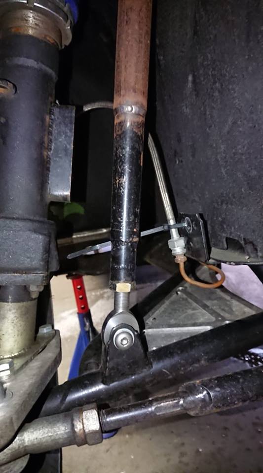
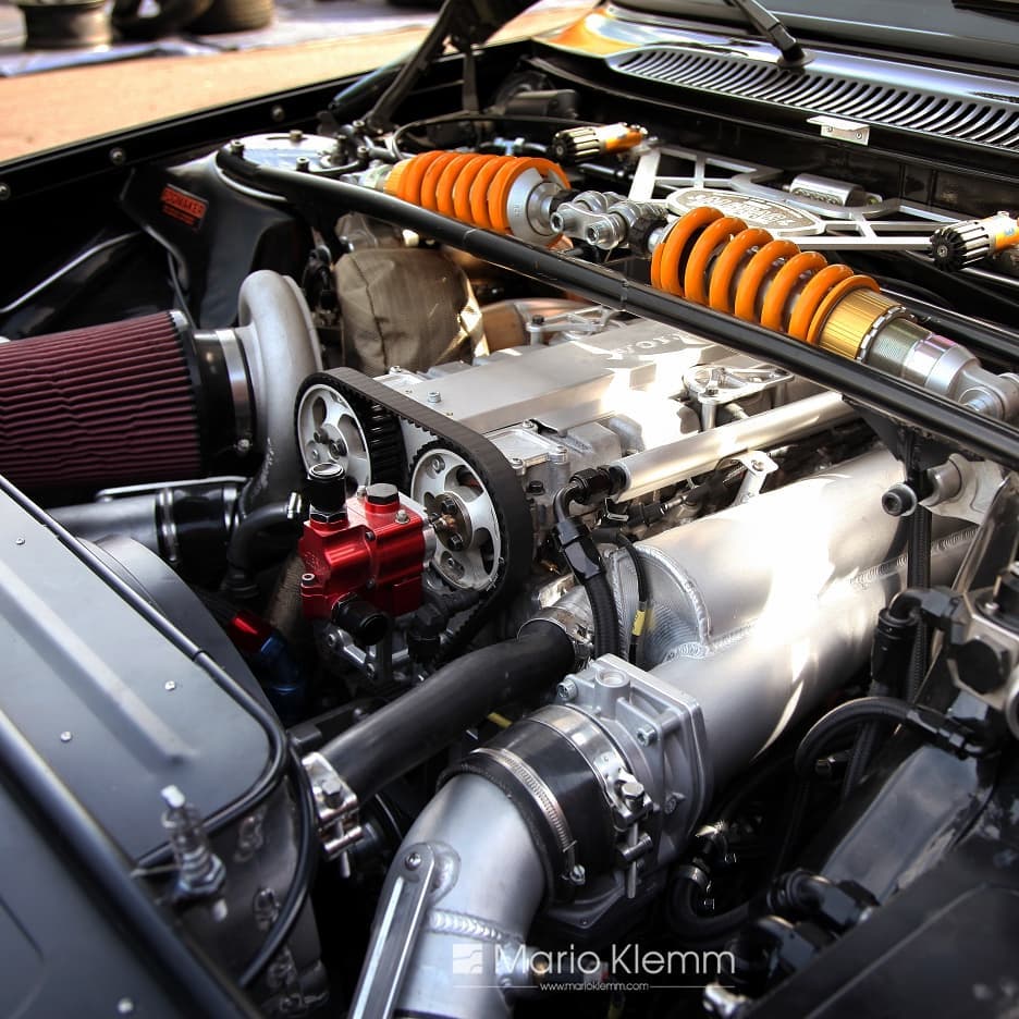
Posted by: Curbandgutter Nov 26 2018, 08:16 PM
Quick update, I finally finished welding the tube frame. My son is designing new lower 996 control arms to extend the front track 1" on each side for a total of 2". The control arm is getting a revised location for a strut to install inboard coilovers on the the mac pherson strut design. The mac pherson strut will be replaced with a sliding shaft and a monoball on a camber/caster plate. I think that this may be a first, not sure, but I haven't seen it on the web. While that is being machined by CSDILLIGAD out of a solid piece of 2026 aluminum on his HASS CNC mill, I will finish bead rolling a new floor. The 3-piece forged modular wheels were supposed to come in this week, keeping my fingers crossed maybe this week. BTW, I decided to convert the rear coilovers to inboard coil overs as well.
Question for the group, does anyone know the specs on the front ball joint for the 996 control arm? I need to source them for the new control arms. Any help would be appreciated. I'm looking for the length and taper and diamters. I'm hoping to find an off the shelf ball joint that I can press into the new control arm.
I would check with Elephant Racing for the ball joint and look at their selection of 996 arms and components.
As for your strut idea, a Volvo owner beat you to it
(not mine, Sweden or Norway)
@http://www.914world.com/bbs2/index.php?showuser=87 can you post a link to this volvo?
Posted by: stownsen914 Nov 27 2018, 06:36 AM
The mac pherson strut will be replaced with a sliding shaft and a monoball on a camber/caster plate. I think that this may be a first, not sure, but I haven't seen it on the web.
If I'm picturing correctly what you are talking about, I remember seeing this on an SCCA tube frame 914 a bunch of years ago - Doug Arnao's car that he ran in GT2. It was one of the iterations of his car. If I recall correctly, he initially built a dual A arm setup for the front suspension but the tech inspectors disallowed it. He wound up running the upper A arm in a fixed position and using a modified 911 strut as an upright. It had a fixed shaft that slid through a spherical bearing or rod end in the fixed upper A arm. And I believe it must have used an external shock absorber (i.e. not part of the strut). It was an interesting way to approach it.
I haven't read through the whole thread, but this is a cool project. I'll have to read more of the thread!
Scott
Posted by: jd74914 Nov 27 2018, 07:34 AM
I like that idea. Are you going that route to try to improve motion ratio? How are you planning on making the sliding shaft? Gutted strut damper?
Posted by: Curbandgutter Nov 27 2018, 10:00 AM
I like that idea. Are you going that route to try to improve motion ratio? How are you planning on making the sliding shaft? Gutted strut damper?
Yes the reason is for the motion ratio since I want to be able to cause a rising compression and I also want the shock to move more than a 1/2". With this setup, the shock will have a full range of movement as opposed to a very limited range. My hope is that this lowered car will not rattle your contact lenses off. In order to tune that, I’m using a shock that is 4 way adjustable. It will be able to be tuned to absorb the freeway ripples effortlessly but then stiffen up in steady state motion. Both compression and rebound will be adjustable for steady state and for rapid motion, hence the 4-way adjustment. As for the sliding shaft, I will look at both gutting the strut damper and also making my own sliding shaft to keep the unsprung weight down. I may make the portion of the shaft that does not move to tie into the camber plate and then put the receiving shaft with bearings onto the unsprung portion of the assembly. I can also move the sway bars up and parallel with the coilovers. This will make adjustments in ride height and sway bar tension very easy.
Posted by: Curbandgutter Dec 11 2018, 04:39 PM
Fitment check.......they finally arrived!
Attached thumbnail(s)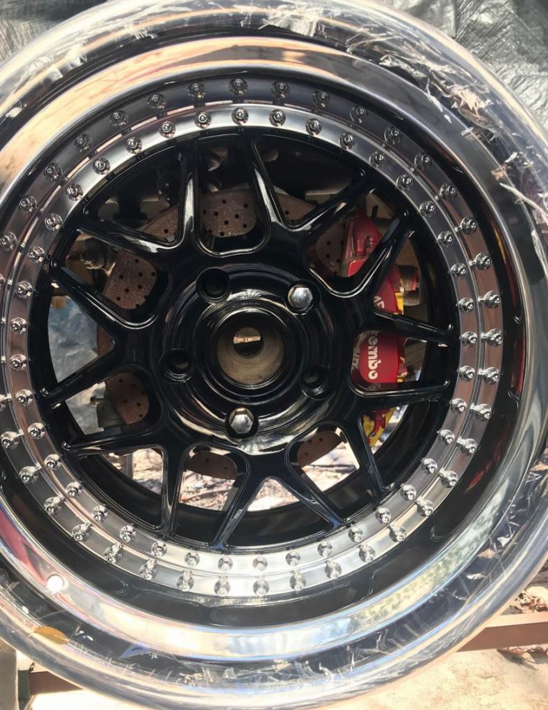
Attached image(s)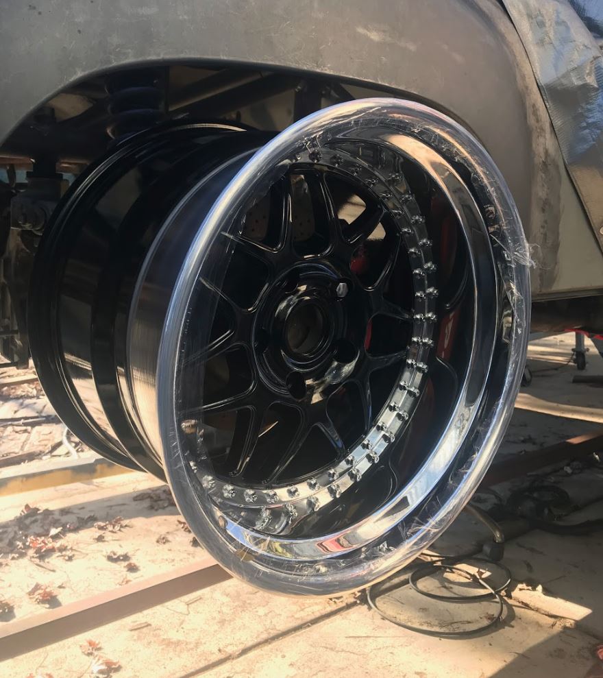
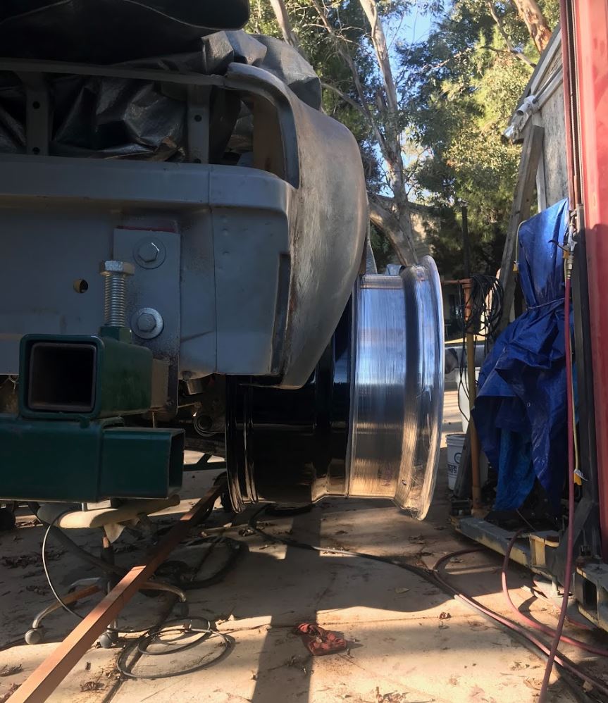
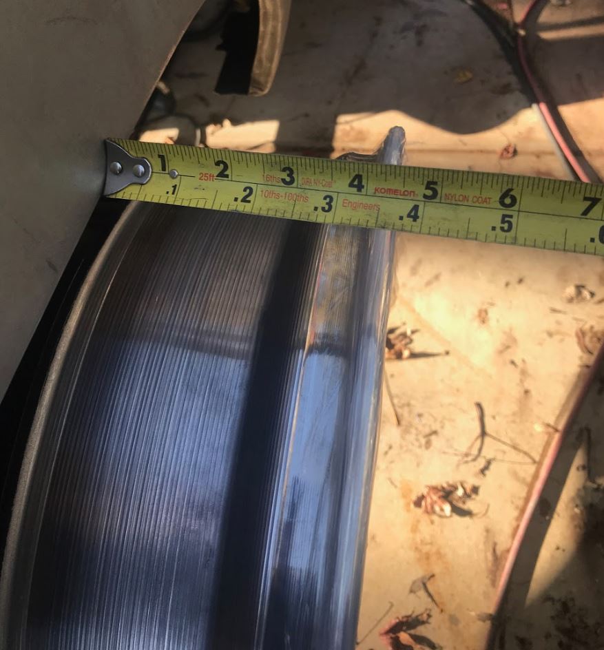
Posted by: Cracker Dec 11 2018, 05:40 PM
My Lord!
T
Posted by: Andyrew Dec 11 2018, 06:26 PM
Holy crap!
You couldn't have tucked that any more? Daaaaaaamn.
This car is going to be WIDE!
I LIKE IT!
Posted by: Larmo63 Dec 11 2018, 08:11 PM

Posted by: 76-914 Dec 11 2018, 08:58 PM
This car makes a statement and it ain't pimping. Bad ass Rudy. I got a name for it. El Curendero
Posted by: Curbandgutter Dec 12 2018, 12:16 PM
Thanks guys.
Andrew I based my offsets on hitting target track widths and was not concerned with tucking the rears in. The front and rear track are now square at 63". The interesting thing with respect to the rear offset is that it's a 0" offset so there will be less eccentricity on the rear wheel bearings. The car will be wide that's for sure. I measures 76 1/2" to the rear rim edges. I figured if I was going through all of the trouble with tube chassis and all, that I was not interested in making a meek rendition of the 914. I'm hoping that with the extra width and the 3" wheel base extension that it will look like a panther crouching and ready to pounce.
Obviously I need to extend the fenders but I want to keep the curve in them rather than a straight extension. I have a couple of ideas to do that.
Kent don't know about the Curandero Come on by and check the wheels out in in person. They are 3-piece forged rims with custom offsets. I really like the look.
Posted by: 76-914 Dec 12 2018, 04:31 PM
Thanks guys.
Andrew I based my offsets on hitting target track widths and was not concerned with tucking the rears in. The front and rear track are now square at 63". The interesting thing with respect to the rear offset is that it's a 0" offset so there will be less eccentricity on the rear wheel bearings. The car will be wide that's for sure. I measures 76 1/2" to the rear rim edges. I figured if I was going through all of the trouble with tube chassis and all, that I was not interested in making a meek rendition of the 914. I'm hoping that with the extra width and the 3" wheel base extension that it will look like a panther crouching and ready to pounce.
Obviously I need to extend the fenders but I want to keep the curve in them rather than a straight extension. I have a couple of ideas to do that.
Kent don't know about the Curandero Come on by and check the wheels out in in person. They are 3-piece forged rims with custom offsets. I really like the look.
I'll stop by as soon as this head cold is finished with me.
I'll bring the V8 this time.
Posted by: Andyrew Dec 12 2018, 04:48 PM
Rudy,
Your essentially going to need to extend the fenders 5", The rear of the fender is where all that dimension is going to look the most odd.
I know you've worked with foam before, possibly a good idea to lay it out in foam and shape it a bit before you start cutting? Maybe do a wire frame of your potential wheel arch location and after putting some foil on your fenders to protect the steel spray some expanding foam on them in multiple layers and start forming it out?
Thats what I did for my V1 dash and it worked out really well. I had issues where I was trying to spray to much in one location and the foam never setting but in general a couple layers made the job easy and I was able to cheaply and easily template out what I want.
You could do this then make cardboard slices for what your fender line is and then be able to transfer those new measurements to the formation of steel?
Fun stuff ahead This will be really fun to watch! Wish I was closer
Posted by: Curbandgutter Dec 12 2018, 04:57 PM
Rudy,
Your essentially going to need to extend the fenders 5", The rear of the fender is where all that dimension is going to look the most odd.
I know you've worked with foam before, possibly a good idea to lay it out in foam and shape it a bit before you start cutting? Maybe do a wire frame of your potential wheel arch location and after putting some foil on your fenders to protect the steel spray some expanding foam on them in multiple layers and start forming it out?
Thats what I did for my V1 dash and it worked out really well. I had issues where I was trying to spray to much in one location and the foam never setting but in general a couple layers made the job easy and I was able to cheaply and easily template out what I want.
You could do this then make cardboard slices for what your fender line is and then be able to transfer those new measurements to the formation of steel?
Fun stuff ahead
This will be really fun to watch! Wish I was closer Thanks for the suggestions, I've never had to extend steel fenders like this, but I have some ideas. The end product is to continue the vanishing edge instead of just extending it straight out like an extrusion.
Posted by: Andyrew Dec 12 2018, 05:07 PM
Rudy,
Your essentially going to need to extend the fenders 5", The rear of the fender is where all that dimension is going to look the most odd.
I know you've worked with foam before, possibly a good idea to lay it out in foam and shape it a bit before you start cutting? Maybe do a wire frame of your potential wheel arch location and after putting some foil on your fenders to protect the steel spray some expanding foam on them in multiple layers and start forming it out?
Thats what I did for my V1 dash and it worked out really well. I had issues where I was trying to spray to much in one location and the foam never setting but in general a couple layers made the job easy and I was able to cheaply and easily template out what I want.
You could do this then make cardboard slices for what your fender line is and then be able to transfer those new measurements to the formation of steel?
Fun stuff ahead
This will be really fun to watch! Wish I was closer Thanks for the suggestions, I've never had to extend steel fenders like this, but I have some ideas. The end product is to continue the vanishing edge instead of just extending it straight out like an extrusion.
I think thats a good idea. thats like what mine do. No where near as wide, but the same vanishing edge could be used.
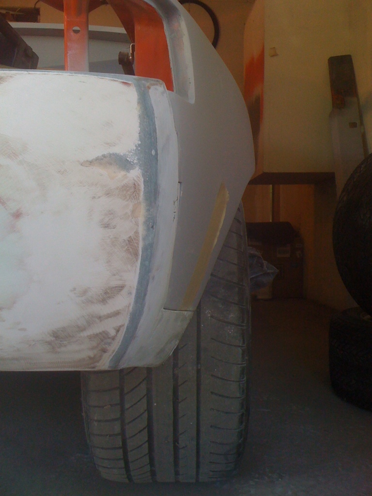
Posted by: rick 918-S Dec 12 2018, 09:20 PM
Thanks guys.
Andrew I based my offsets on hitting target track widths and was not concerned with tucking the rears in. The front and rear track are now square at 63". The interesting thing with respect to the rear offset is that it's a 0" offset so there will be less eccentricity on the rear wheel bearings. The car will be wide that's for sure. I measures 76 1/2" to the rear rim edges. I figured if I was going through all of the trouble with tube chassis and all, that I was not interested in making a meek rendition of the 914. I'm hoping that with the extra width and the 3" wheel base extension that it will look like a panther crouching and ready to pounce.
Obviously I need to extend the fenders but I want to keep the curve in them rather than a straight extension. I have a couple of ideas to do that.
Kent don't know about the Curandero Come on by and check the wheels out in in person. They are 3-piece forged rims with custom offsets. I really like the look.
http://www.914world.com/bbs2/index.php?showtopic=132215&hl=
I stretched these flares pretty far. Since yours are already on you will likely need to use another method.
Posted by: Curbandgutter Dec 13 2018, 01:10 PM
Oh I see, you extended them from the quarter panel. They looked good after you finished "massaging" them into shape.
Posted by: Curbandgutter Dec 13 2018, 01:21 PM
Here is a shot from the rear: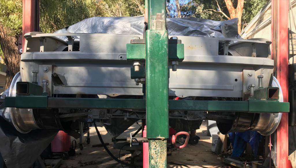
Front Rim: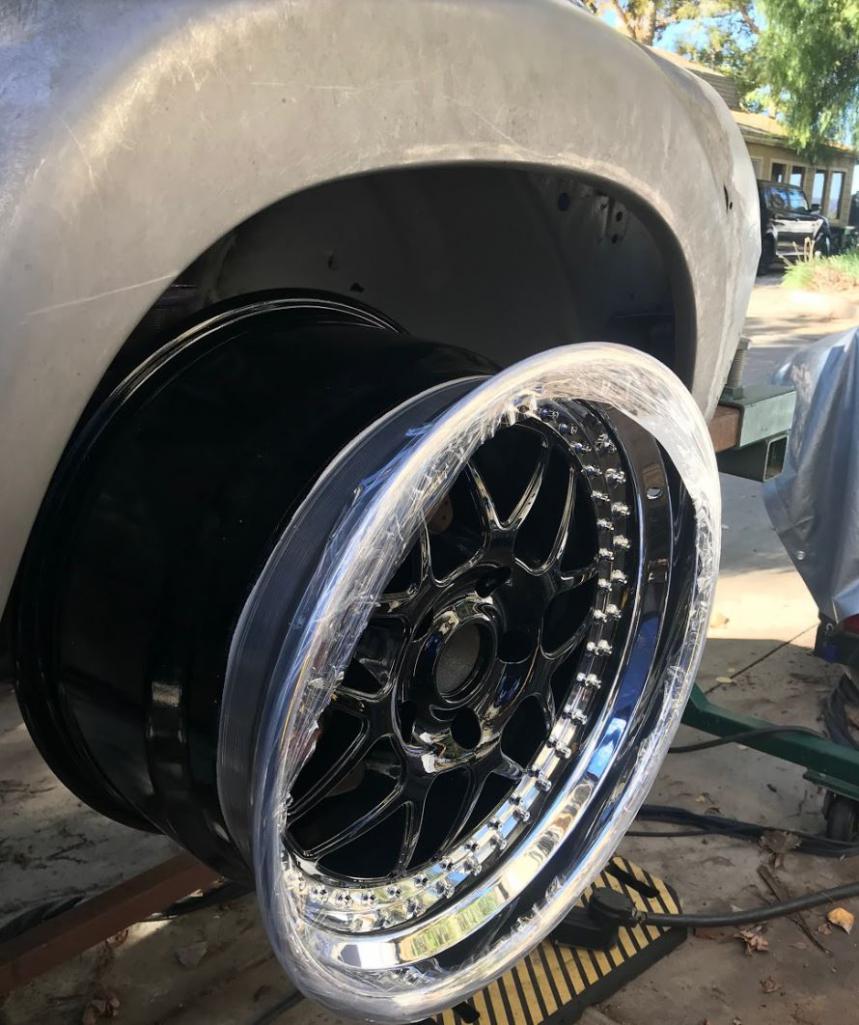
This is how much I'm needing to extend front fender + 1 1/2" since the lower control arm is being pushed out to give me the 63" square track.: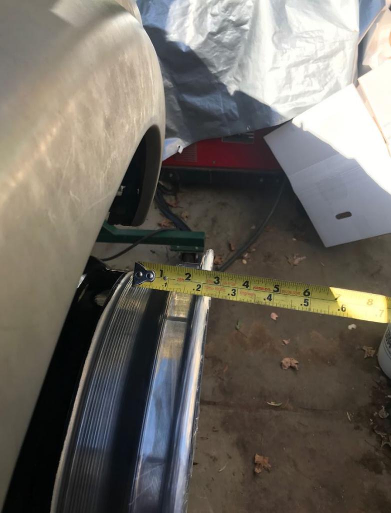
We're not messing around now!
Posted by: barefoot Dec 13 2018, 01:27 PM
Watch the Blinky episodes where they spread the flares WAY out
Posted by: Curbandgutter Dec 13 2018, 01:31 PM
Watch the Blinky episodes where they spread the flares WAY out
Don't understand what you mean by this. Who or what are the Blinky episodes? Can you put a link in?
Posted by: defianty Dec 13 2018, 01:44 PM
Here's the Binky Epispode.
https://www.youtube.com/watch?v=mB4NXA_vNWs&t=499s
Posted by: Curbandgutter Dec 13 2018, 01:52 PM
Thanks! The Binky flares are fiberglass and I don't think much of that will transfer to making steel flares. Thanks though!
Posted by: sixnotfour Dec 13 2018, 02:20 PM
food for thought..
https://www.youtube.com/watch?v=PI0vpvaL7Vc
Posted by: Curbandgutter Dec 13 2018, 02:50 PM
Close but not what I’m going to do. I want to keep the vanishing edge so when you see the fender from the side profile the current flat vertical area will shrink. The fenders will look more curved. Do you know if that car is from one of the world guys?
Posted by: sixnotfour Dec 13 2018, 03:08 PM
ya its boxy ,,, It was , has been sold , I dont know where it got of to..
Posted by: Curbandgutter Dec 13 2018, 04:36 PM
This is what I'm thinking of: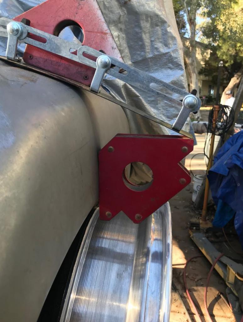
Seems like the "flat" portion will be reduced by about 2 1/2":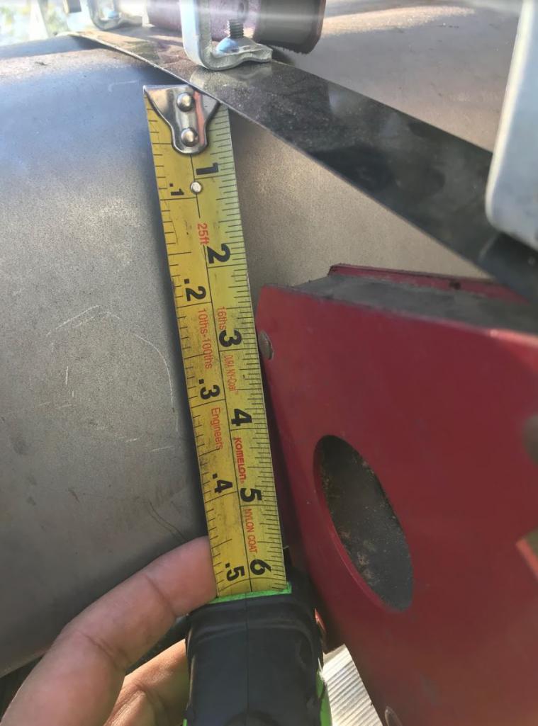
Posted by: Andyrew Dec 13 2018, 05:53 PM
I think that will work, just afraid of the rear section getting so tight.
That's why I was thinking you might need to foam it out to be able to try out a few options before you start cutting and welding.
Unless you absolutely have the design in your head your going with.
Another pic for idea refference. A more rounded fender.you can see the front fender is slightly flatter.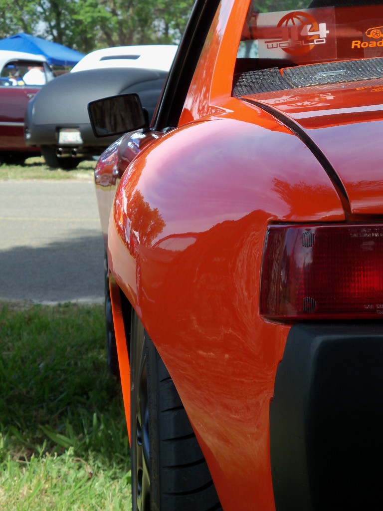
Posted by: Curbandgutter Dec 13 2018, 06:55 PM
Thanks, Andrew for your comments and suggestions. I'm thinking that the final product will be like yours but edgier. I still want the flat design elements that are found throughout the 914. So it will look like yours but with a vertical flat element as found in the 916 flares.
Posted by: Cracker Dec 13 2018, 07:33 PM
Keep in mind, where "wide flared teeners" usually have issues is between 10/2 in the top center; and on the inner chassis if you run a reasonable amount of camber. Keep up the good work...remember, it doesn't have to be nicer than Chris's!
PS: I know you are already aware of ALL of this but get the tires on there - with how large they will be it will indeed have to be "boxy' to carry the edge.
T
Posted by: Curbandgutter Dec 13 2018, 09:21 PM
Keep in mind, where "wide flared teeners" usually have issues is between 10/2 in the top center; and on the inner chassis if you run a reasonable amount of camber. Keep up the good work...remember, it doesn't have to be nicer than Chris's!
PS: I know you are already aware of ALL of this but get the tires on there - with how large they will be it will indeed have to be "boxy' to carry the edge.
T
Good things to remember. However, I have the 996 track which pushes the wheels out. I have plenty of room on the inside wheel wells. With respect to the boxy look, I don’t want to completely remove that or it will look like a 914 with 911 fenders. I still want some of the 914 flat edges. And absolutely, I wouldn’t attempt cutting fenders without tires......... and with regard to Chris YES IT DOES YES IT DOES, YES IT DOES
Posted by: djway Dec 14 2018, 02:34 AM
I am sure you already know this but just in case, fully compress the suspension with tires on when hanging the fenders to make sure that the tires do not rub when bottomed out
Posted by: Marv's3.6six Dec 14 2018, 05:10 PM
Wow Rudy I just read thru your entire thread, you are truly building a monster, very impressed. Keep up the good wok.
Posted by: Curbandgutter Dec 14 2018, 05:15 PM
Wow Rudy I just read thru your entire thread, you are truly building a monster, very impressed. Keep up the good wok.
Thanks Marv.......like I told you at the last 914 event at Seal Beach, your car was one of the cars that I looked to for inspiration.
Posted by: sixnotfour Jul 1 2019, 01:01 PM
Rudy !! ![]()
Posted by: Andyrew Jul 1 2019, 01:32 PM
Rudy !!
Posted by: sb914 Jul 1 2019, 03:56 PM
Rudy !!
@http://www.914world.com/bbs2/index.php?showuser=2744 get out of my head! I was just thinking about rudys build this am!
Posted by: ValcoOscar Jul 1 2019, 04:15 PM
Rudy !!
@http://www.914world.com/bbs2/index.php?showuser=2744 get out of my head! I was just thinking about rudys build this am!
Me too...this morning I drove down the 15 fwy on my way to Temecula and I saw his house off the fwy but I couldn't see his 914 beast anywhere....
We need an update!!!!
Oscar
Posted by: Rand Jul 1 2019, 05:05 PM
Oscar, unlock the italics button.
Posted by: Curbandgutter Sep 3 2019, 03:06 PM
Hey guys, a little update. The project is still ongoing.....but I've been slowed down due to.......(insert typical excuses here). But really though, I completed the frame and am now working on the floor. I am waiting for a bead roller and English wheel that I ordered. The bead roller is a Mitler Bros with Covell forming dies and a host of other dies that I will use to make floor and to make the pieces that I will need to shape the "wider" fenders. The English wheel is a Metal Ace. I've also ordered a Roper Whitney 48" box break. Once all of that comes in I will be able to complete the floor. I'm also moving into a 50' x 24' shop. Up to this point I have been working outdoors so I really can't do much when it's too hot or weld when it's windy or work when it gets dark. Now I will be able to work whenever I feel like it so I'm expecting to get way more done. Also, there this month I find out if we sell our property of stay in it. If we sell, then I'm building a new house and then you know that this project will stall. If we don't sell then there won't be a stall. Also, I figured out a way to widen the front track of the 996 suspension without having to machine new control arms......stay tuned since it's very cool way that keeps all of the suspension geometry and can use factory parts.
Attached thumbnail(s)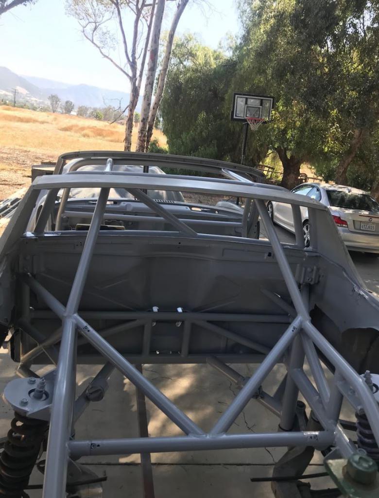
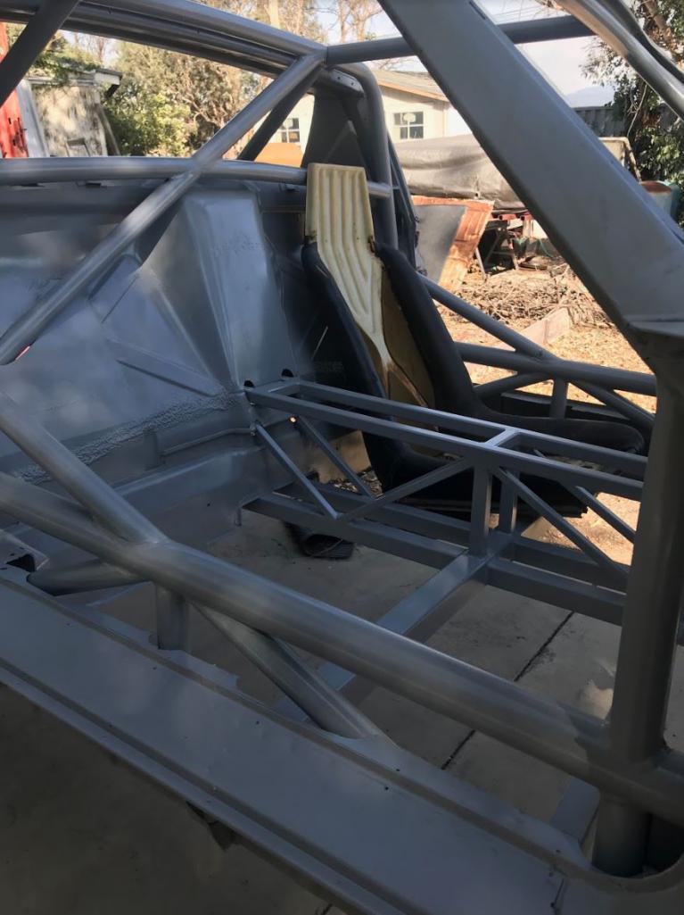
Attached image(s)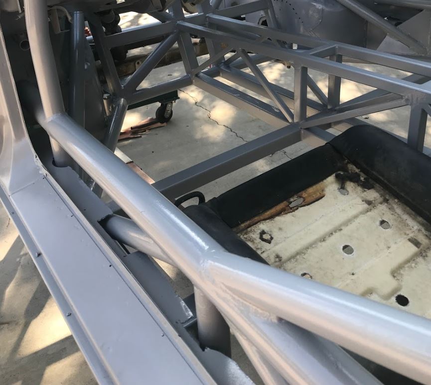
Posted by: tygaboy Sep 3 2019, 03:17 PM
Rudy! So good to hear from you. Great to see things are continuing to move along. And I hope the sale or not goes the way you want.
Posted by: Cracker Sep 3 2019, 03:18 PM
Not enough steel...add more!
T
Posted by: Curbandgutter Sep 3 2019, 03:20 PM
Not enough steel...add more!
T
Damn it, I knew it.
Posted by: ValcoOscar Sep 3 2019, 03:38 PM
Always nice to see updates from you Rudy. Keep that Monster 914 alive!!!!
You will be rewarded!!! 
Oscar
Posted by: 76-914 Sep 4 2019, 08:17 AM
I'll be over to make a new pan for my BBQ pit once you receive the bead roller. Good to see your back on it. Which Car Dealership wants your property?
Posted by: Chris H. Sep 4 2019, 08:45 AM
Not enough steel...add more!
T
Damn it, I knew it.
CHASSIS FLEX = 0.0
Posted by: jd74914 Sep 4 2019, 09:47 AM
Awesome! I was wondering how you were doing the other day Rudy.
Can you pull the engine/trans package out of the top with those tubes removed?
Posted by: Curbandgutter Sep 4 2019, 10:34 AM
Awesome! I was wondering how you were doing the other day Rudy.
Can you pull the engine/trans package out of the top with those tubes removed?
@http://www.914world.com/bbs2/index.php?showuser=1659 Yes sir you can. That's why I used those removable welded adapters. It's a tight fit but the engine and transaxle come out of the top. It's kind of unique for a 914.
Posted by: Curbandgutter Sep 4 2019, 10:35 AM
Not enough steel...add more!
T
Damn it, I knew it.
CHASSIS FLEX = 0.0
@Chris_H. or close.
As soon as the floor is done I will throw on chassis table and twist it like I did before and see what i can get out of it. I'm sure that it will be stiff enough so that I can jack it up from front wheel and be able to open and close the doors. We shall see.
Posted by: Curbandgutter Sep 4 2019, 10:37 AM
I'll be over to make a new pan for my BBQ pit once you receive the bead roller.
Good to see your back on it. Which Car Dealership wants your property? @http://www.914world.com/bbs2/index.php?showuser=9964 yes it will be able to do that for sure. I'll call you when I move into my shop and the roller comes in. Its a Mittler with the industrial motor. And it's a hotel chain that may be buying me out. However attempted to sell to Carvana but they were not ready to move to this area yet.
Posted by: Curbandgutter Sep 4 2019, 10:41 AM
Rudy! So good to hear from you. Great to see things are continuing to move along. And I hope the sale or not goes the way you want.
Thanks @http://www.914world.com/bbs2/index.php?showuser=19241 . Either way it will be good. We're in a good spot...don't need to sell and its a great location. However, if we do sell, then we will build a one-story rambling Spanish hacienda with a massive garage and a forever 360 degree view of city lights 1000 ft above the valley floor. Can't lose either way.
Posted by: Curbandgutter Sep 4 2019, 10:43 AM
Always nice to see updates from you Rudy. Keep that Monster 914 alive!!!!
You will be rewarded!!!
Oscar
Thanks @http://www.914world.com/bbs2/index.php?showuser=16669 ! Hey I may need two pieces for my strut towers to be cut on you r fancy cnc plasma cutter. I can email you a dxf file if you can do it.
Posted by: ValcoOscar Sep 4 2019, 11:15 AM
Always nice to see updates from you Rudy. Keep that Monster 914 alive!!!!
You will be rewarded!!!
Oscar
Thanks @http://www.914world.com/bbs2/index.php?showuser=16669 ! Hey I may need two pieces for my strut towers to be cut on you r fancy cnc plasma cutter. I can email you a dxf file if you can do it.
Send me file....I'll deliver pcs back to you. Maybe we'll meet up with @http://www.914world.com/bbs2/index.php?showuser=9964 at our favorite breakfast joint one Saturday.

Oscar
Posted by: Curbandgutter Sep 4 2019, 11:26 AM
Always nice to see updates from you Rudy. Keep that Monster 914 alive!!!!
You will be rewarded!!!
Oscar
Thanks @http://www.914world.com/bbs2/index.php?showuser=16669 ! Hey I may need two pieces for my strut towers to be cut on you r fancy cnc plasma cutter. I can email you a dxf file if you can do it.
Send me file....I'll deliver pcs back to you. Maybe we'll meet up with @http://www.914world.com/bbs2/index.php?showuser=9964 at our favorite breakfast joint one Saturday.
Oscar
@http://www.914world.com/bbs2/index.php?showuser=16669 definitely. Let's do it. @http://www.914world.com/bbs2/index.php?showuser=9964 where you at?
Posted by: 76-914 Sep 4 2019, 08:29 PM
Always nice to see updates from you Rudy. Keep that Monster 914 alive!!!!
You will be rewarded!!!
Oscar
Thanks @http://www.914world.com/bbs2/index.php?showuser=16669 ! Hey I may need two pieces for my strut towers to be cut on you r fancy cnc plasma cutter. I can email you a dxf file if you can do it.
Send me file....I'll deliver pcs back to you. Maybe we'll meet up with @http://www.914world.com/bbs2/index.php?showuser=9964 at our favorite breakfast joint one Saturday.
Oscar
@http://www.914world.com/bbs2/index.php?showuser=16669 definitely. Let's do it. @http://www.914world.com/bbs2/index.php?showuser=9964 where you at?
LMK when. I've got Red Rocks in two weeks but other than that I'm available.
Posted by: Sideways Feb 9 2020, 12:29 PM
Any updates on this beast?
Posted by: Curbandgutter Jun 8 2020, 06:02 PM
Well after a long hiatus I'm back. I moved the project into a workshop with a bunch of new fabricator tools that I needed to complete. It's on!!
Attached thumbnail(s)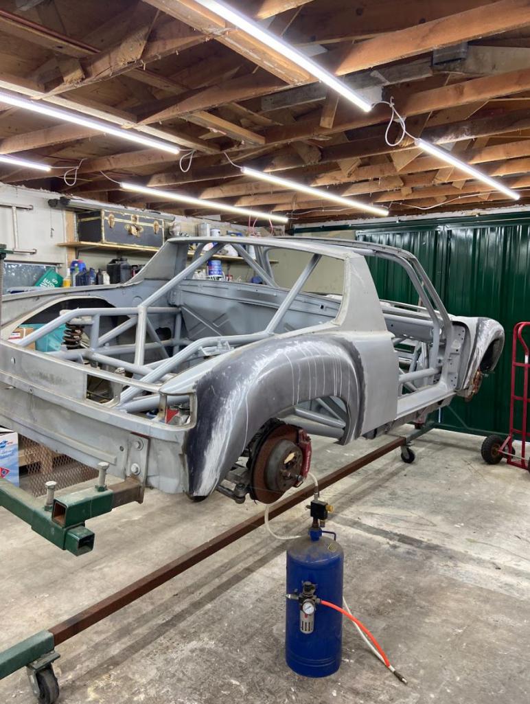
Attached image(s)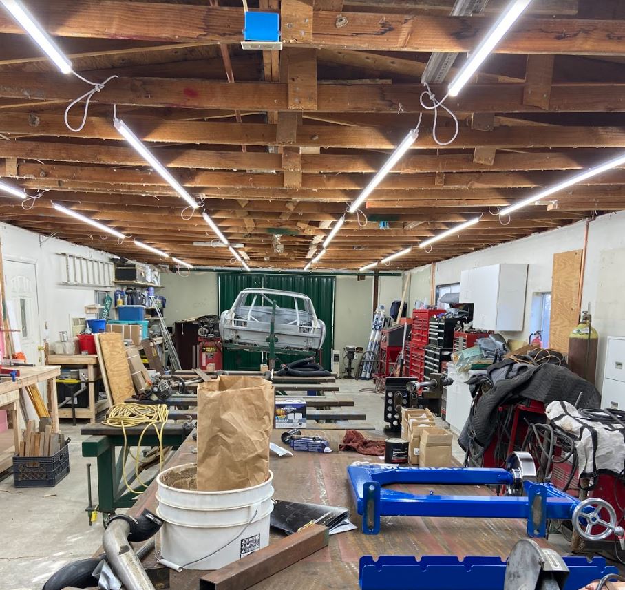
Posted by: tygaboy Jun 8 2020, 06:33 PM
Yaaa Rudy! You're back! I've missed you.
(Phew... I was beginning to worry.)
Now get your ass in gear, dude. We need to see progress!
Posted by: sb914 Jun 8 2020, 06:55 PM
Hey Rudy !!!
Glad your back ... hope you’re doing good...
Posted by: Cracker Jun 8 2020, 07:15 PM

Posted by: Rand Jun 8 2020, 07:17 PM
Posted by: 76-914 Jun 9 2020, 09:21 AM
Wow! Looks larger than you described. I need get over there and check it out. Do we have an "envious emoji"?
Posted by: Mueller Jun 9 2020, 09:35 AM
Nice shop, plenty of space to work on the 914. Glad to see more progress on this car.
Posted by: FourBlades Jun 9 2020, 04:01 PM
Whoooo!!!!
Looks like a nice shop!
John
Posted by: rhodyguy Jun 9 2020, 10:04 PM
You have an incredible number of tool chests.
Posted by: Blue6 Jun 9 2020, 10:13 PM
Glad your back. Your thread is fantastic.
Posted by: Blue6 Jun 9 2020, 10:13 PM
Dup post..
Posted by: Curbandgutter Jul 20 2020, 07:54 PM
I've started building the floor pan 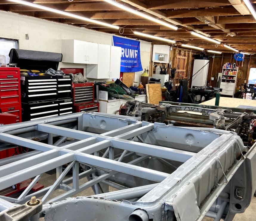
but I first needed to add the supports for the 914 seats 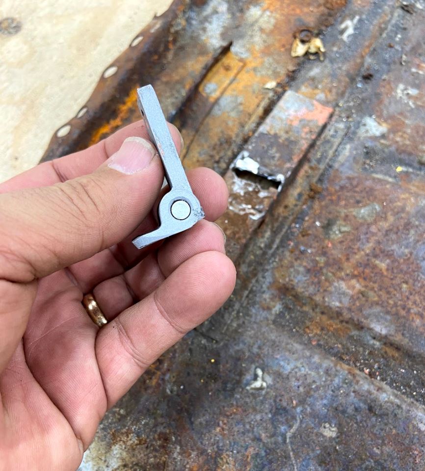
and for the Tilton pedal assembly. 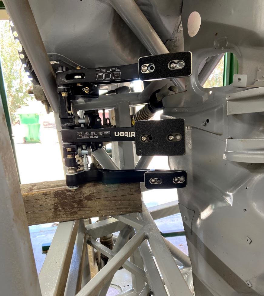
I was able to shift the seats 1-1/2" closer to the center of the car and the pedal assembly 3" further away from the center of the car. As you can see the brake pedal almost aligns with the steering wheel centerline 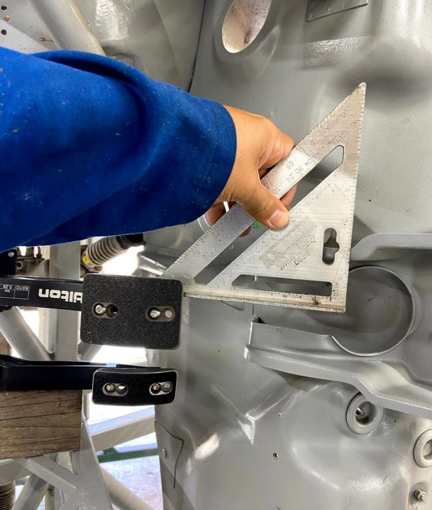
By doing this I was able to more closely align the seats and the pedals with the steering wheel centerline. In doing this I found out that I am in need of the seat elevation control tab that attached to the floor pan.
If anybody is cutting one up let me know as I need this part. 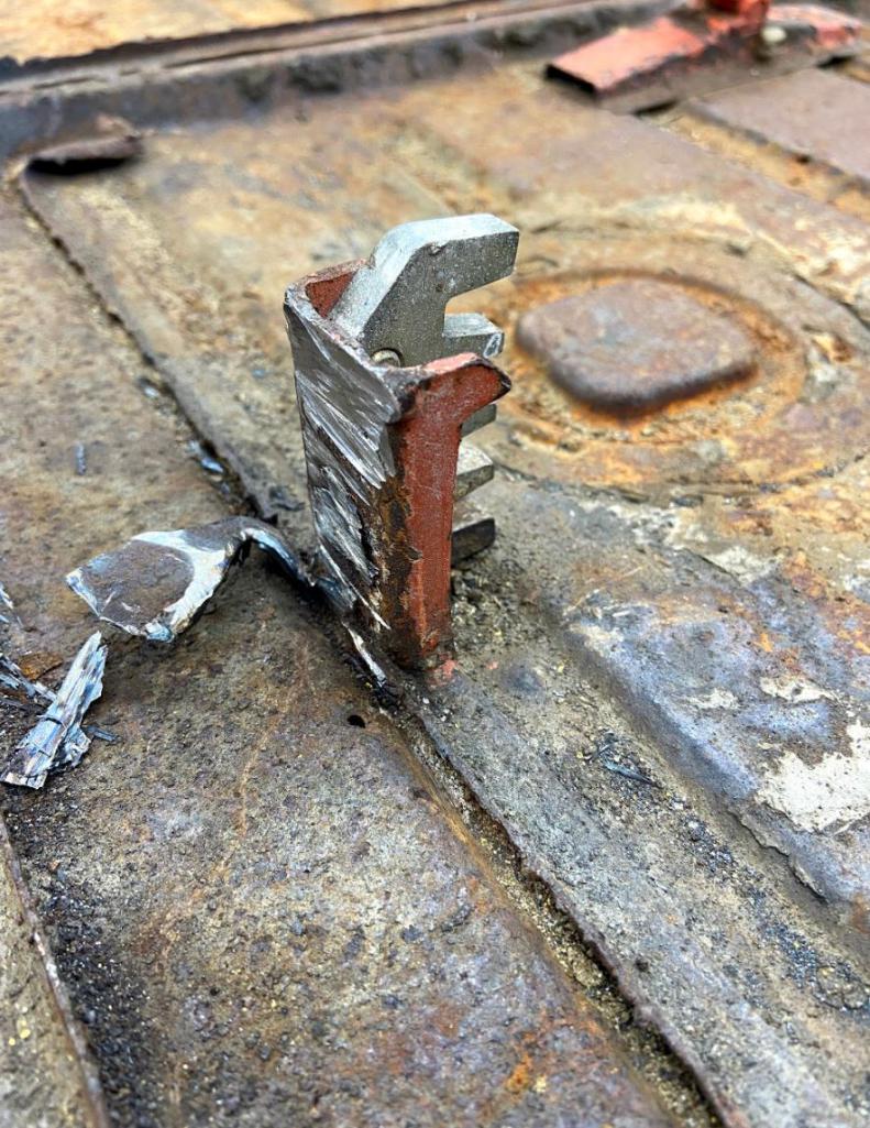
ALSO THANKS EVERYONE FOR THE WELCOME BACK......ITS NICE TO BE BACK!!
Attached thumbnail(s)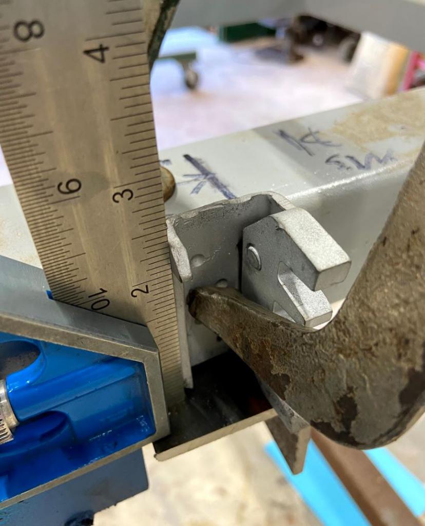
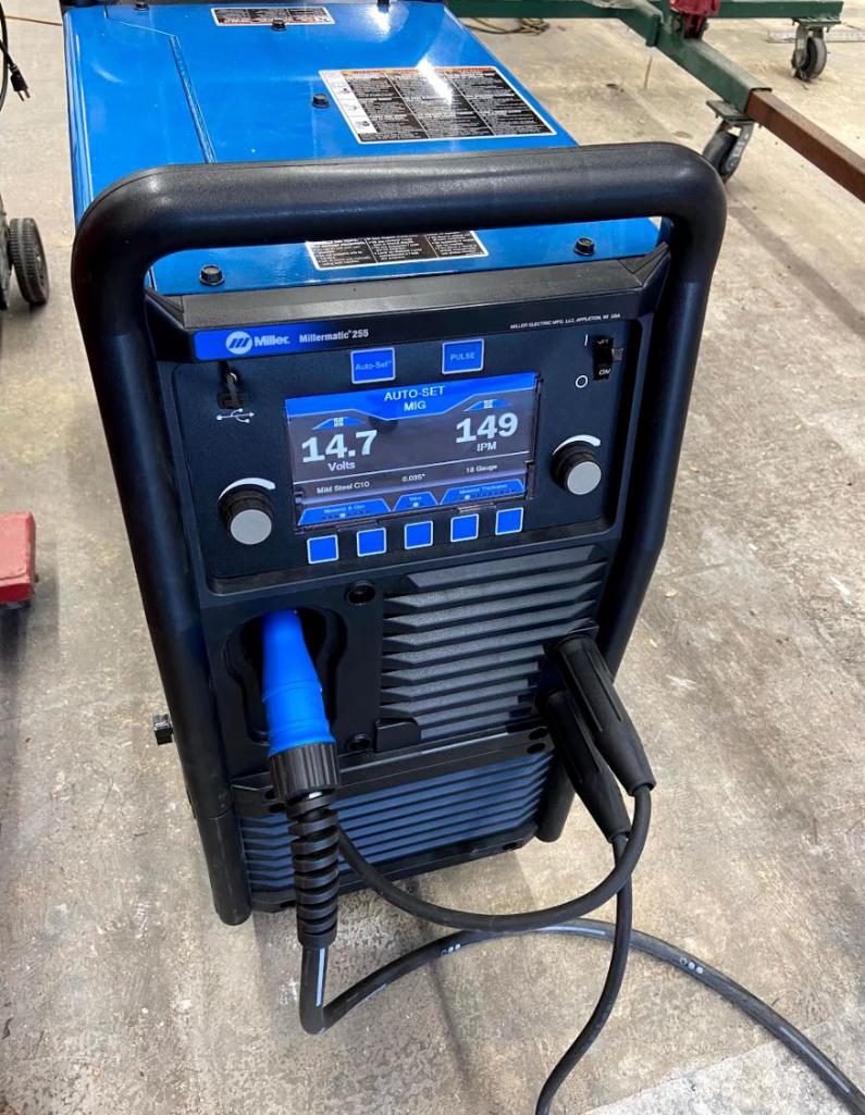
Attached image(s)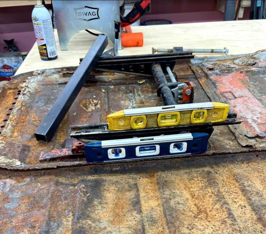
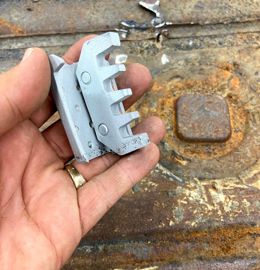
Posted by: 76-914 Jul 20 2020, 08:05 PM
Rudy's shop will give a Tool Whore wood. I've not seen Chris' but I'll bet they are similar. IIRC, @http://www.914world.com/bbs2/index.php?showuser=1319 had a car that was being cannibalized a few weeks ago. I'll probably drop by sometime this week while I'm waiting on parts.
Posted by: Curbandgutter Jul 20 2020, 08:09 PM
Rudy's shop will give a Tool Whore wood.
I've not seen Chris' but I'll bet they are similar. IIRC, @bdstone had a car that was being cannibalized a few weeks ago. I'll probably drop by sometime this week while I'm waiting on parts. hopefully that IIRC guy still has that part. If he's local I can come by and cut it out of the car.
Posted by: 76-914 Jul 20 2020, 08:11 PM
we were just texting one another. I'll point him this way.
Posted by: bdstone914 Jul 20 2020, 08:29 PM
I have those parts.
I have on on a chunk of cross member and can cut it off.
The driver and passenger brackets are different. Is what you pictured the one you need or the one you have? I am not sure they can be swapped.
The one I have on the cross member is exactly like what you pictured. I think I cut both from the parts car.
Easier to ship unless you like to drive
@http://www.914world.com/bbs2/index.php?showuser=15637
hopefully that IIRC guy still has that part. If he's local I can come by and cut it out of the car.
[/quote]
Posted by: bdstone914 Jul 20 2020, 08:33 PM
Rudy's shop will give a Tool Whore wood.
I've not seen Chris' but I'll bet they are similar. IIRC, @bdstone had a car that was being cannibalized a few weeks ago. I'll probably drop by sometime this week while I'm waiting on parts. hopefully that IIRC guy still has that part. If he's local I can come by and cut it out of the car.
Attached thumbnail(s)
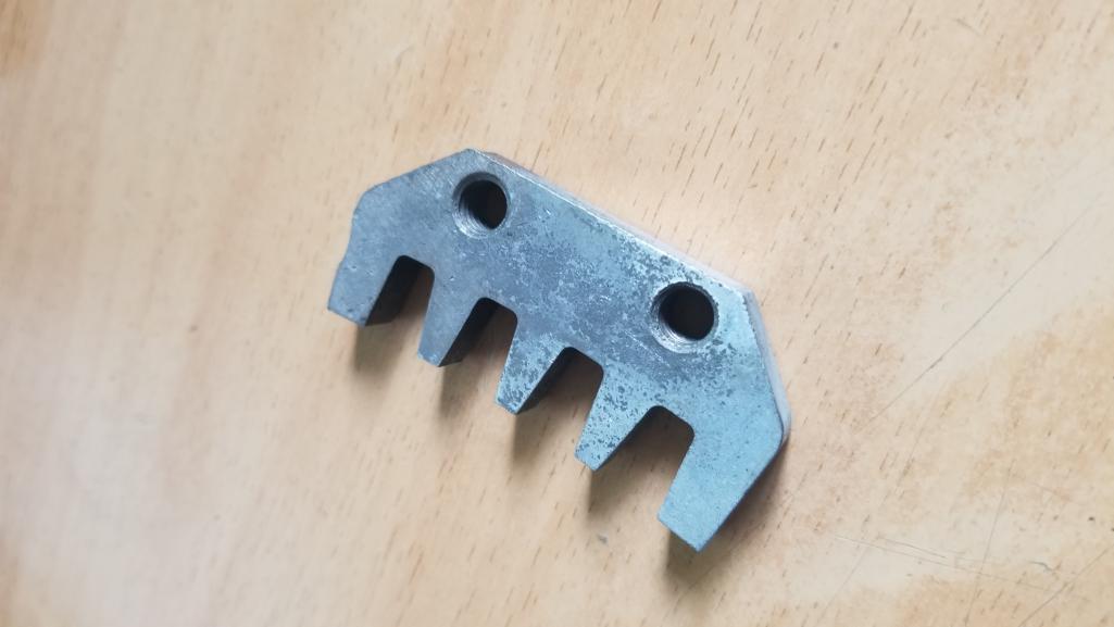
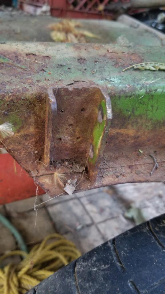
Posted by: Curbandgutter Jul 20 2020, 09:14 PM
[quote name='bdstone914' date='Jul 20 2020, 07:29 PM' post='2835664']
I have those parts.
I have on on a chunk of cross member and can cut it off.
The driver and passenger brackets are different. Is what you pictured the one you need or the one you have? I am not sure they can be swapped.
The one I have on the cross member is exactly like what you pictured. I think I cut both from the parts car.
Easier to ship unless you like to drive
@http://www.914world.com/bbs2/index.php?showuser=15637
hopefully that IIRC guy still has that part. If he's local I can come by and cut it out of the car.
[/quote]
[/quote]
Yes cut out entire cross member and I'll "surgically" remove the part I need. And you're right , the driver and passenger are different. I need the passenger side. PM me with price so we can make arrangements.
Posted by: Curbandgutter Aug 1 2020, 04:25 PM
UPDATE: PEDAL ASSEMBLY AND 911 STYLE DASH
Installed the Numeric shifter. Cut 7/8" solid stock p0lugs and tapped for M6 bolts inserted into tube steel frame by cutting 7/8" hole and inserting tapped round plugs.
Used a sacrificial piece to be able to holesaw the offset round plug
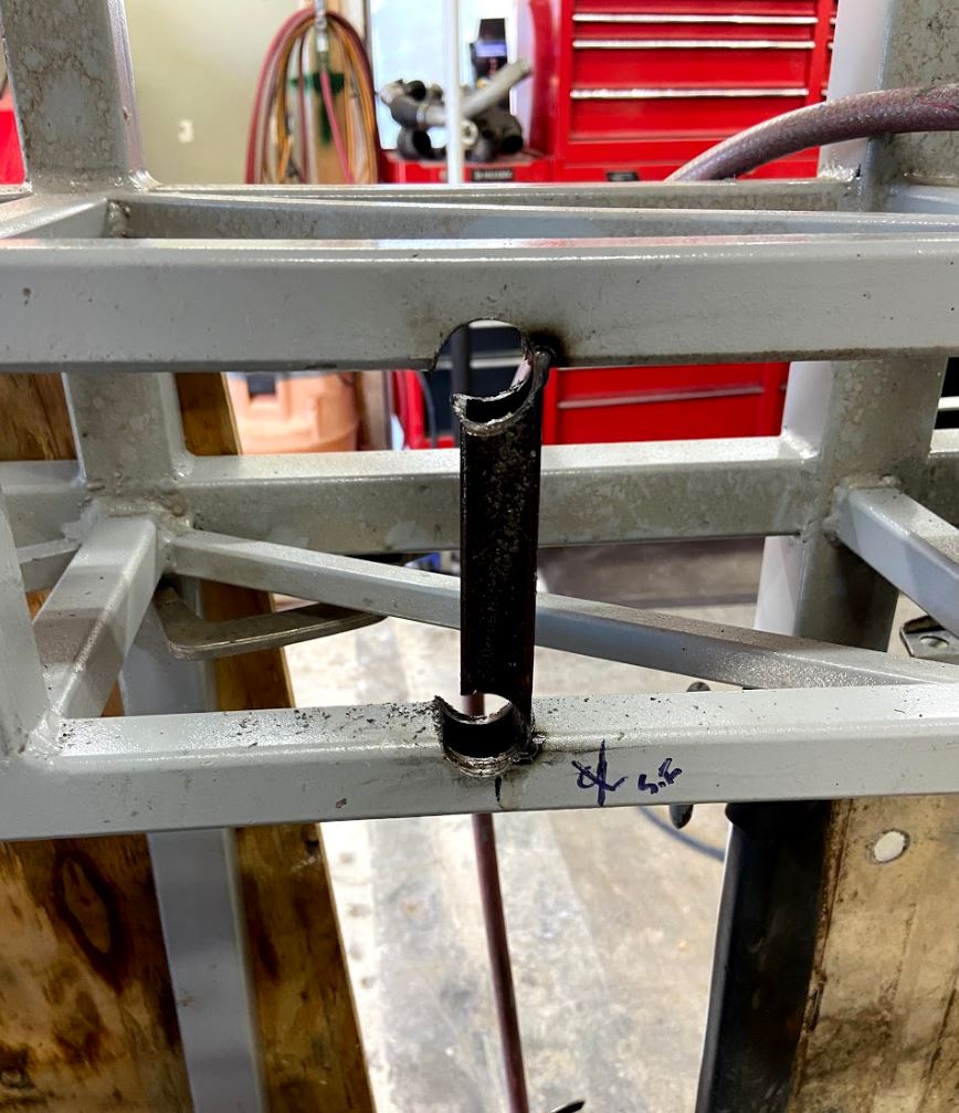
Cut all the way through 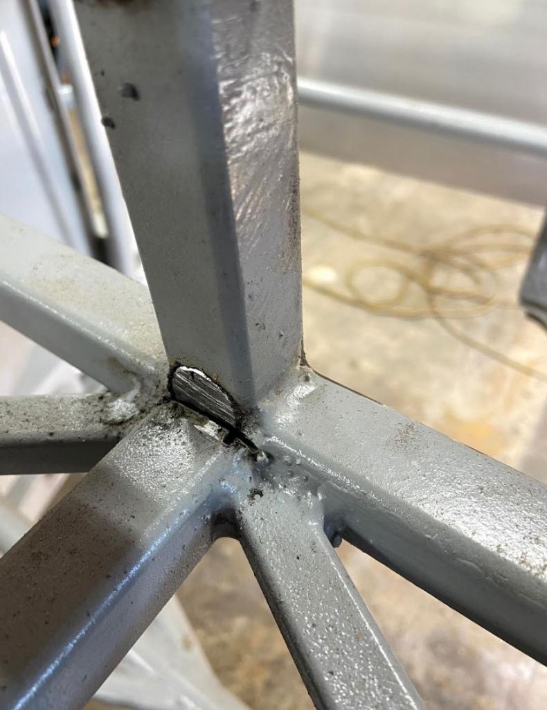
Insert round plugs and weld 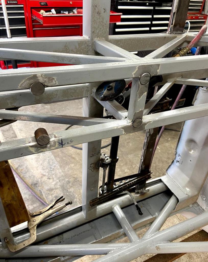
Install Numeric Shifter 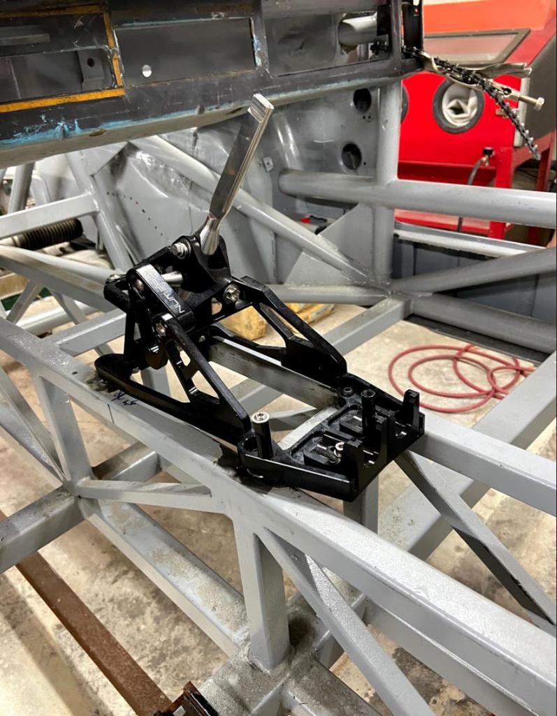
Install foot pedal to frame 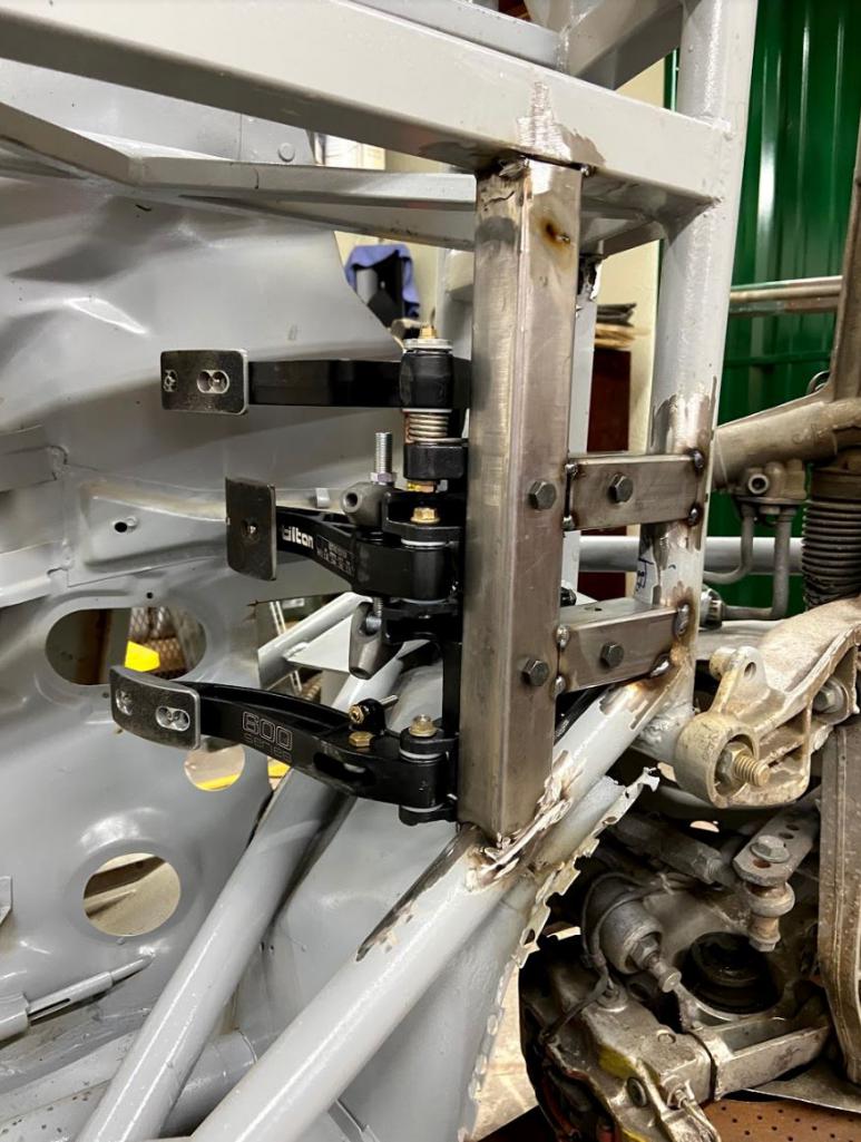
Foot pedal assembly is as close as possible to the center line of the steering wheel 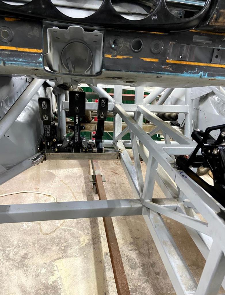
Cut 914 Dash to fit into the tube frame 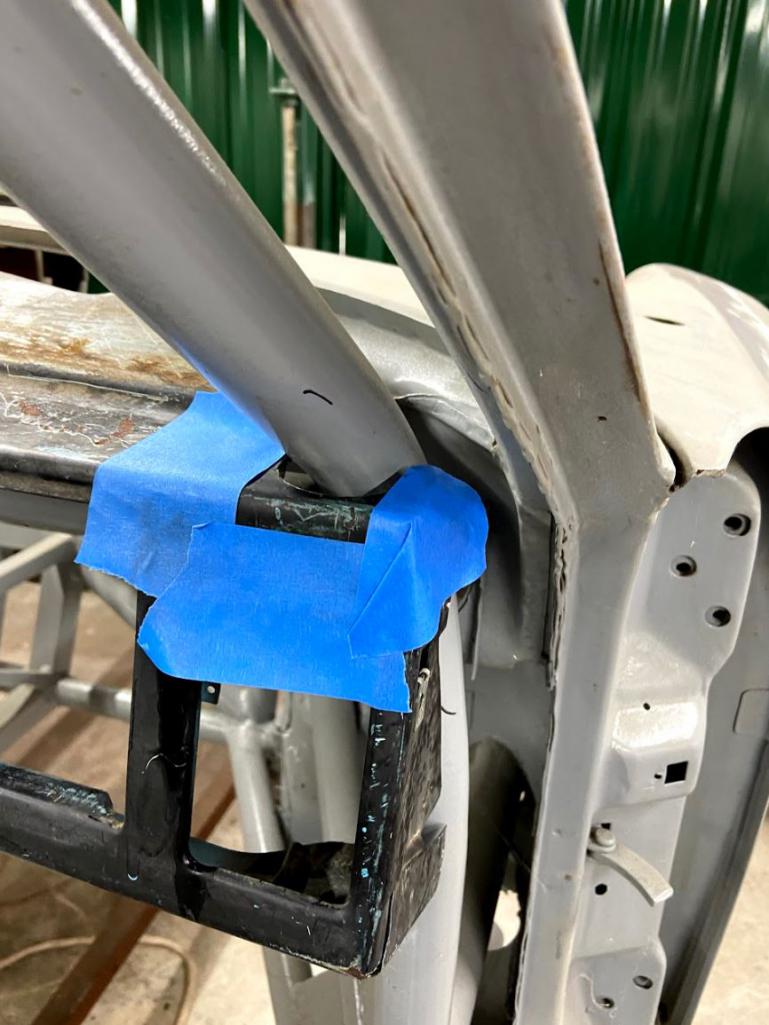
Installed Getty Design 5-Gage Dash. 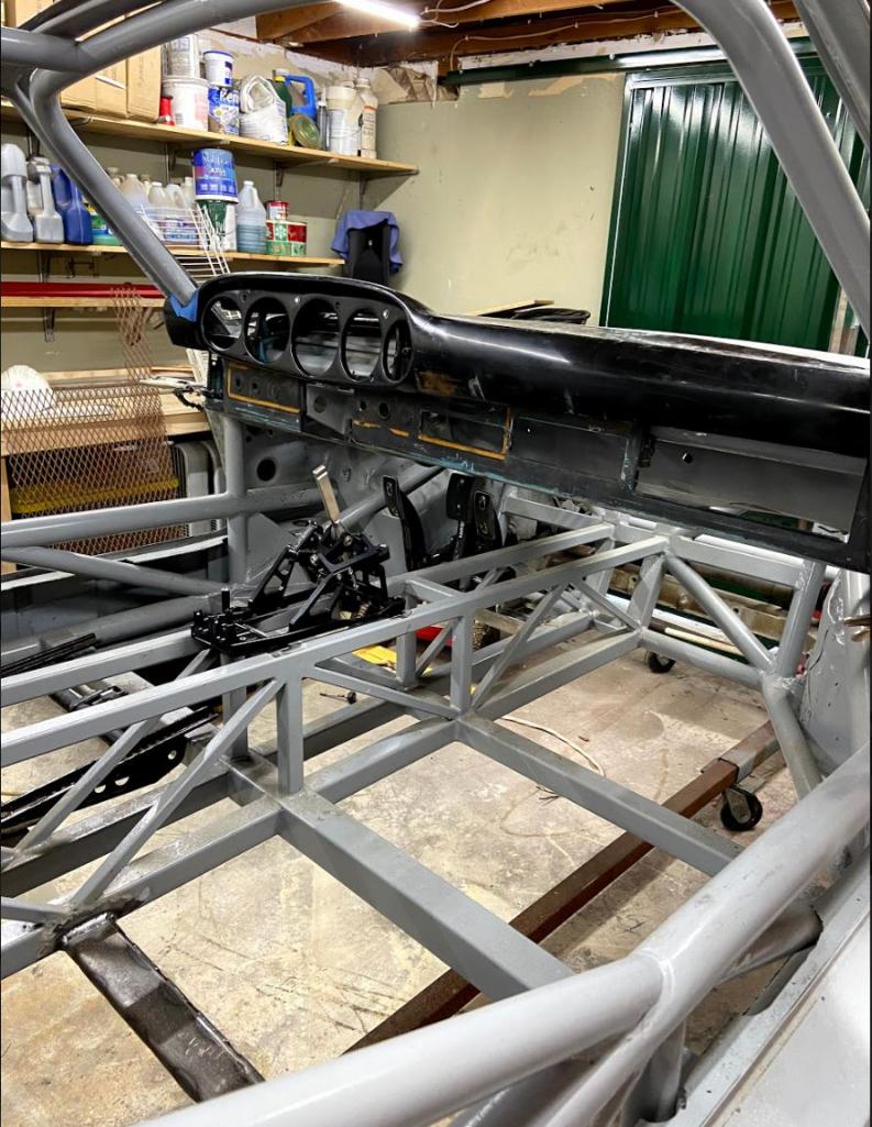
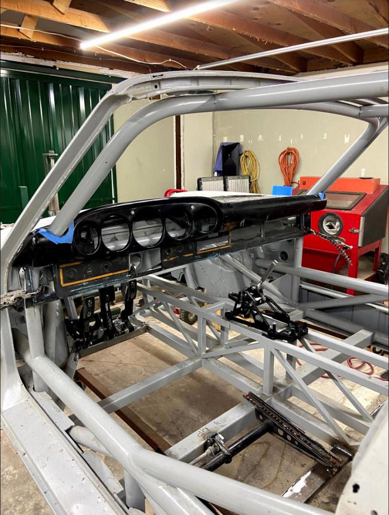
Posted by: tygaboy Aug 1 2020, 05:40 PM
I love 914 World posts that have virtually zero 914 content.
Great progress, Rudy!
Posted by: sixnotfour Aug 1 2020, 06:30 PM
I Like the
getty 911 topper and 914 lower, when peeps use the whole 911 dash ...Why ?? its a 914
Posted by: 76-914 Aug 1 2020, 07:22 PM
Somebody is having fun. Looks good Rudy.
Posted by: Curbandgutter Nov 16 2020, 07:32 PM
WOW, finished floor. Didn't think it was going to be that much work!!
Attached thumbnail(s)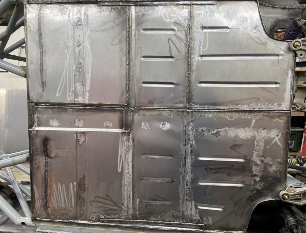
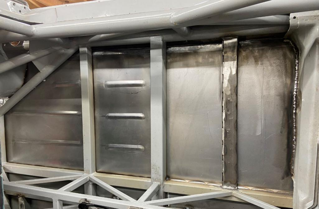
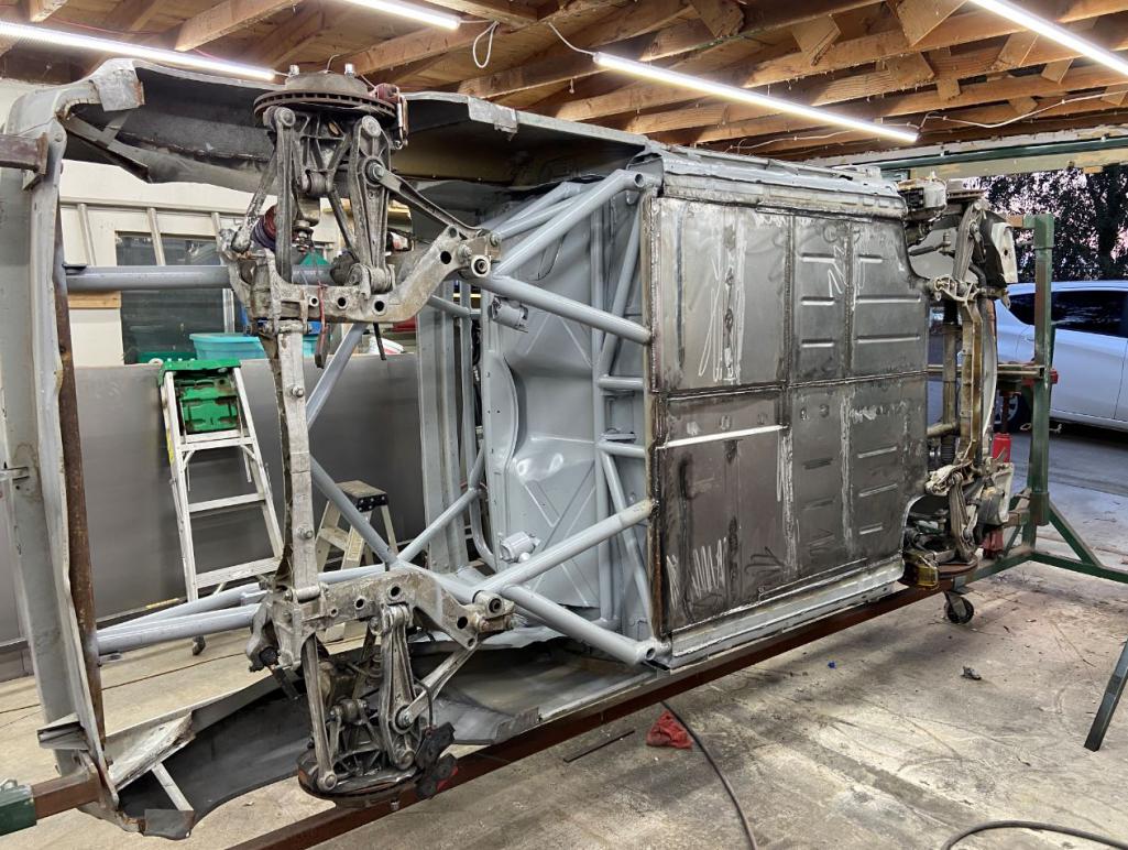
Attached image(s)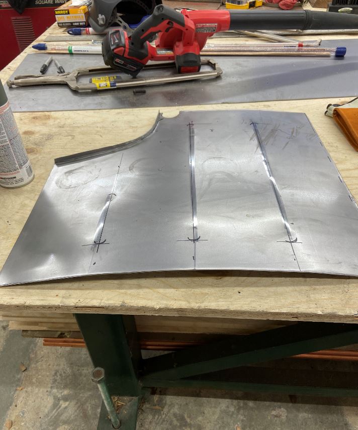
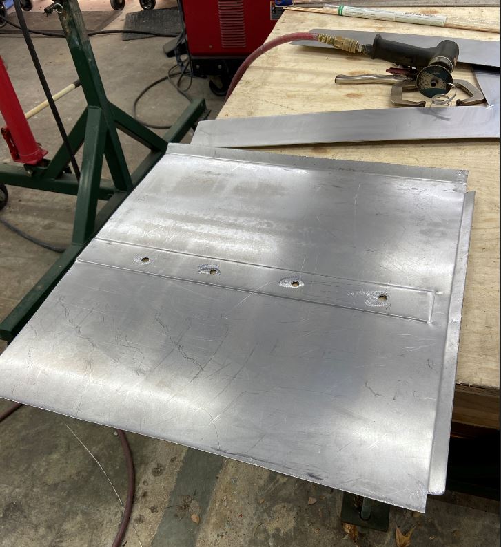
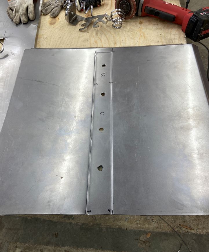
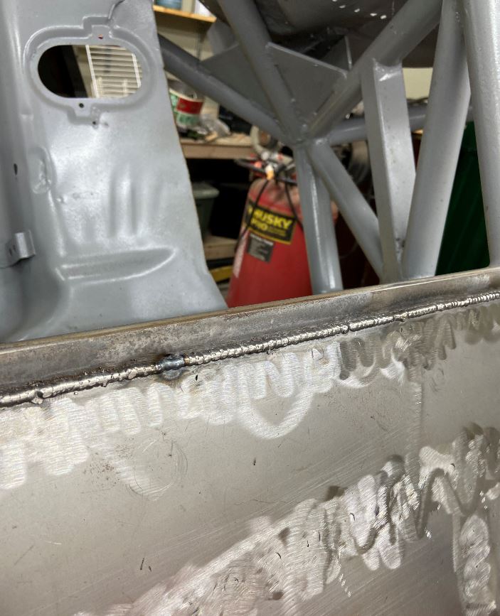
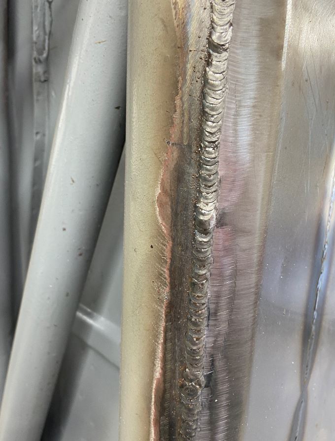
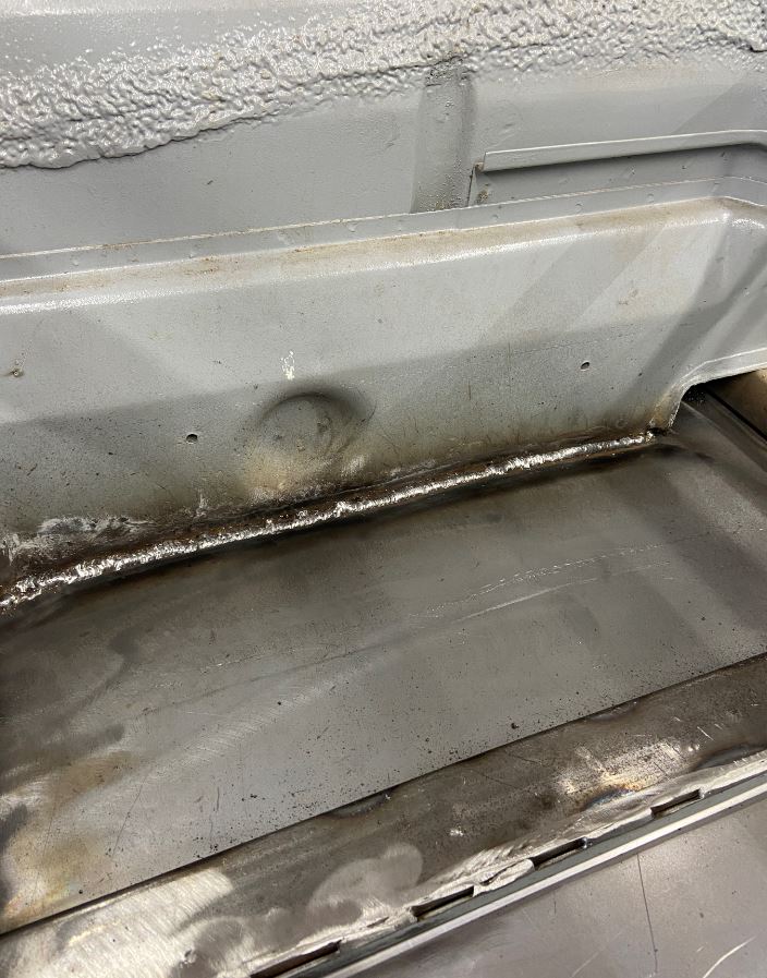
Posted by: Andyrew Nov 16 2020, 07:41 PM
Rudy,
I've got to tell you I think about this car often
Love the progress!! Thats a LOT of welding!
Posted by: Curbandgutter Nov 16 2020, 08:20 PM
Rudy,
I've got to tell you I think about this car often
Love the progress!! Thats a LOT of welding!
Andrew thanks man. Yeah this was a big milestone. More welding on that floor than the entire build so far.
Posted by: Maltese Falcon Nov 16 2020, 08:51 PM
Rudy's work... "Checks all the boxes" !!!
Posted by: tygaboy Nov 16 2020, 09:36 PM
Awesomeness!
Looking REALLY nice, Rudy!
Posted by: PanelBilly Nov 16 2020, 09:49 PM
Posted by: 76-914 Nov 16 2020, 10:25 PM
Looks great Rudy. I need to stop by and see your progress again.
Posted by: 914werke Nov 16 2020, 10:55 PM
Danm how'd I miss this build.. Crazy!!
Posted by: AZBanks Nov 17 2020, 07:59 AM
That is a lot of dimes. Nice welding.
Posted by: ValcoOscar Nov 17 2020, 09:34 AM
Rudy
So thrilled you're still at it. I seem to remember that awesome BBQ you prepared us several years back.
Hope you and your family are doing well.
Keep us updated on your progress
Posted by: Curbandgutter Nov 17 2020, 12:49 PM
THANKS GUYS,
The body work remaining is
1) make a front trunk
2) tie in rear trunk
3) finish interior long cover
4) make interior tunnel cover
5) flare out front and rear fenders and additional 5 or 6 inches.
suspension work remaining is
6) my son is currently designing and machining the front control arms to include a 3" front track widening and connections to remove strut and transfer to inboard coil overs.
I'm feeling like doing 2,3,4 and 5 first while son does 6. Will leave 1 once I figure out how to vent this thing out. I want to try something different.
Posted by: Curbandgutter Nov 23 2020, 09:08 PM
CHECK OUT THESES LONGS!!! The are accessible now so that I can run radiator, ac and electrical lines in them. I created access. Used nutserts and dimple dies to attach with button head screws.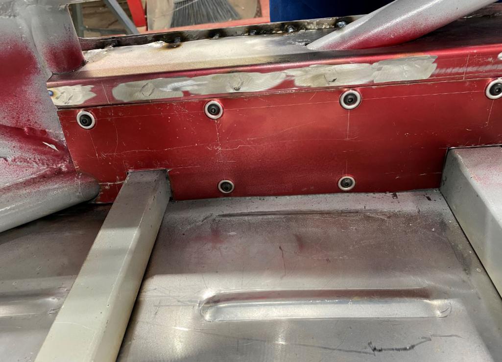
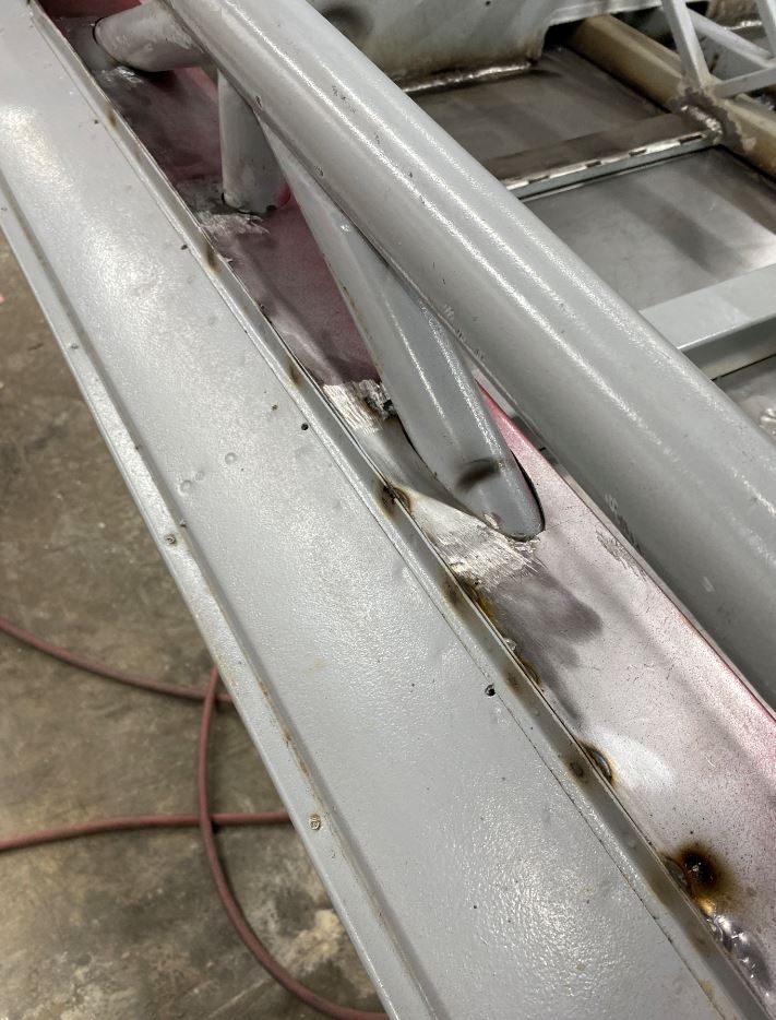
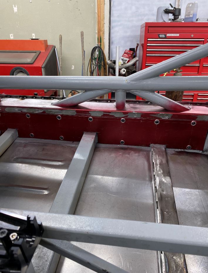
this is how I made the shear transfer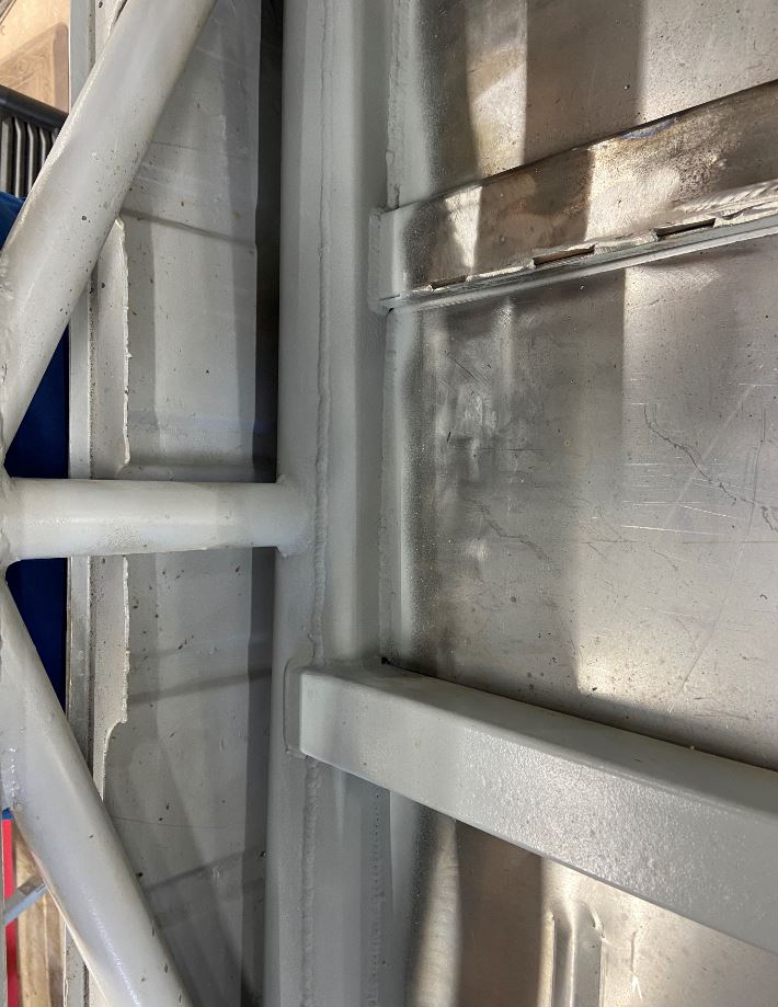
the floor is attached to the tube frame now in shear!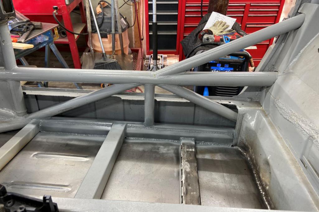
Posted by: horizontally-opposed Nov 23 2020, 10:21 PM
There are some wildly, wildly cool builds going on right now. And this is definitely one of them. Hat's off on the creativity, workmanship, and direction.
Can't wait to see this hit the road, but enjoying the journey...
Posted by: Curbandgutter Jan 3 2021, 06:54 PM
Update: Completed both removable long covers. Did this so that I can run radiator and ac lines inside of the longs.
Using Langmuir Pro Plasa Cutter to cut sheet metal. I fabricated everything on the table that is painted red. Had to modify the table to my liking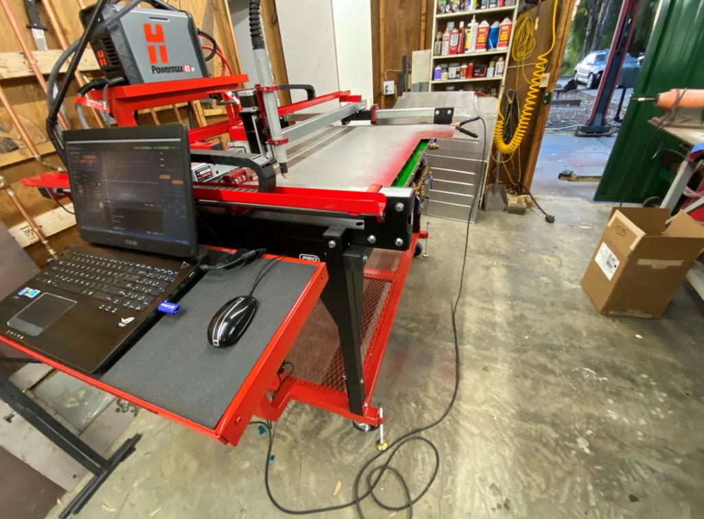
So I cut out the long covers and a bunch of ac/vent holes that I'm closing up.
I closed every single opening along the firewall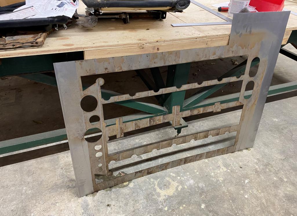
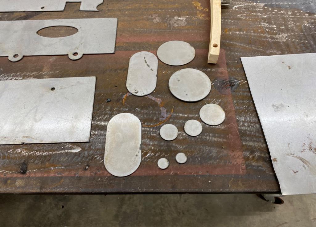
I put an offset in the stationary cover so that the removable cover fits close to flush 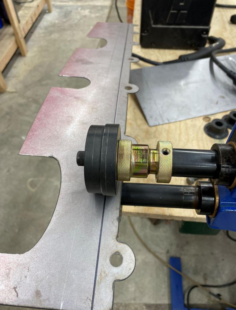
Bending longs on magnetic brake 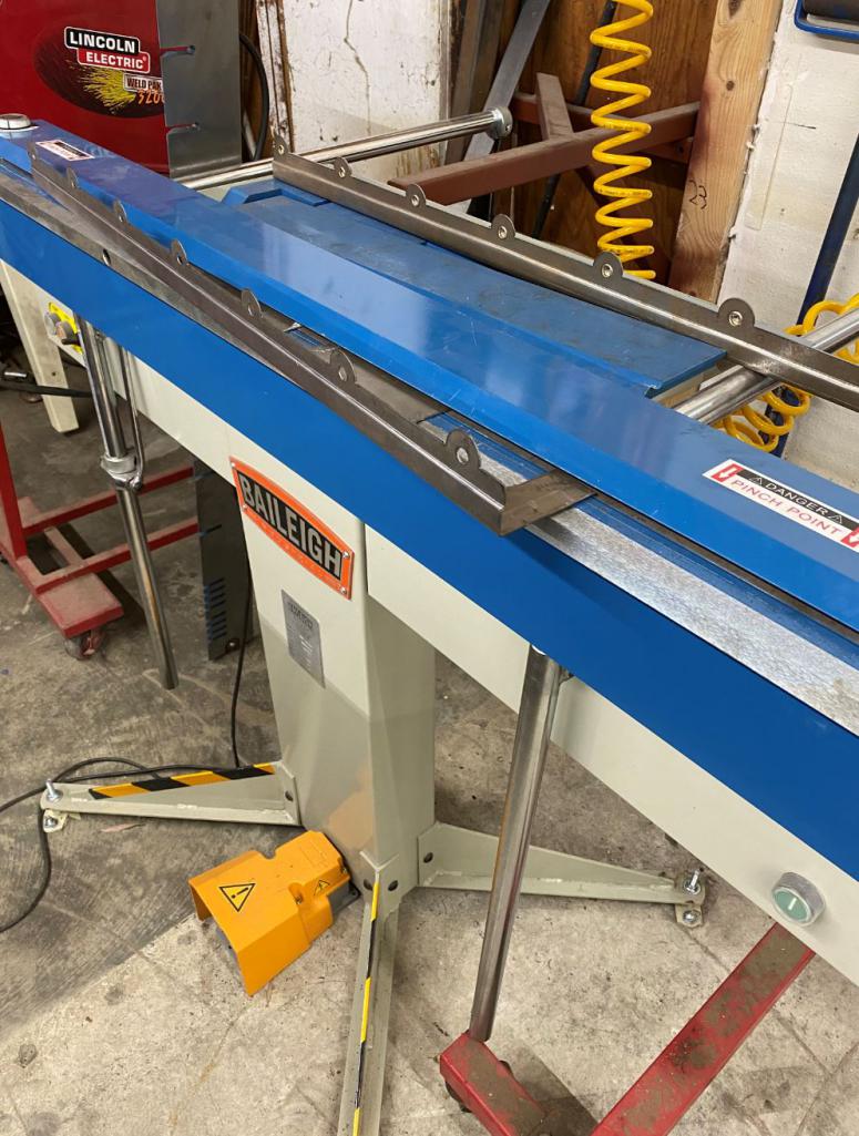
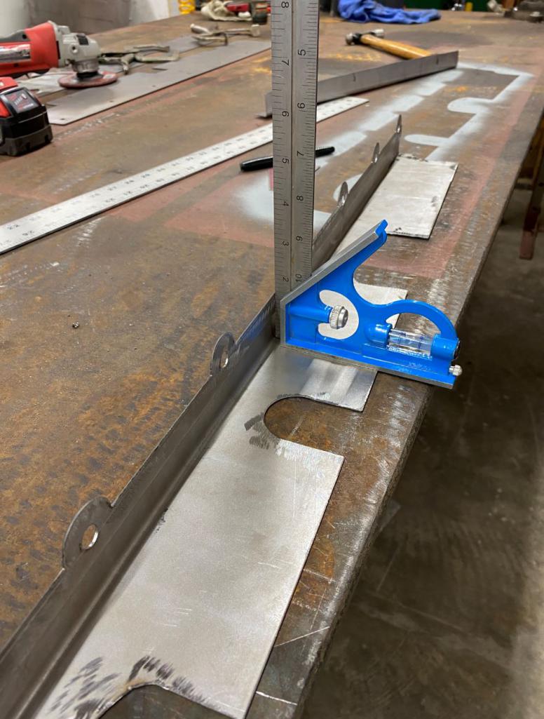
Adding rivnuts to make it all removable 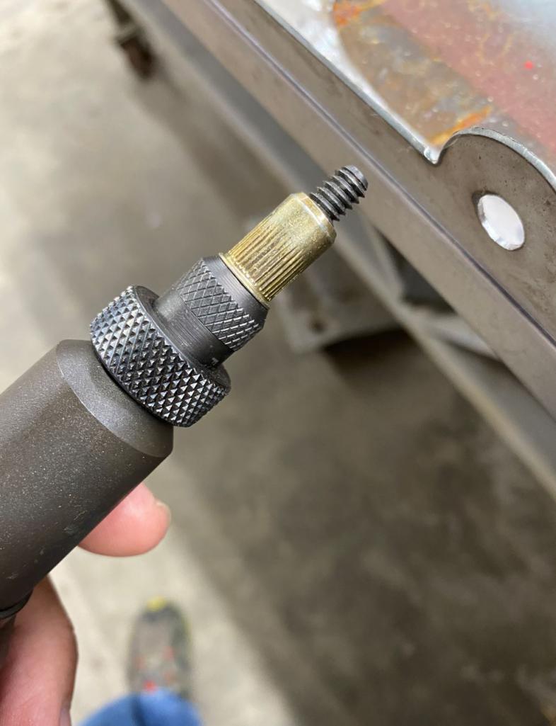
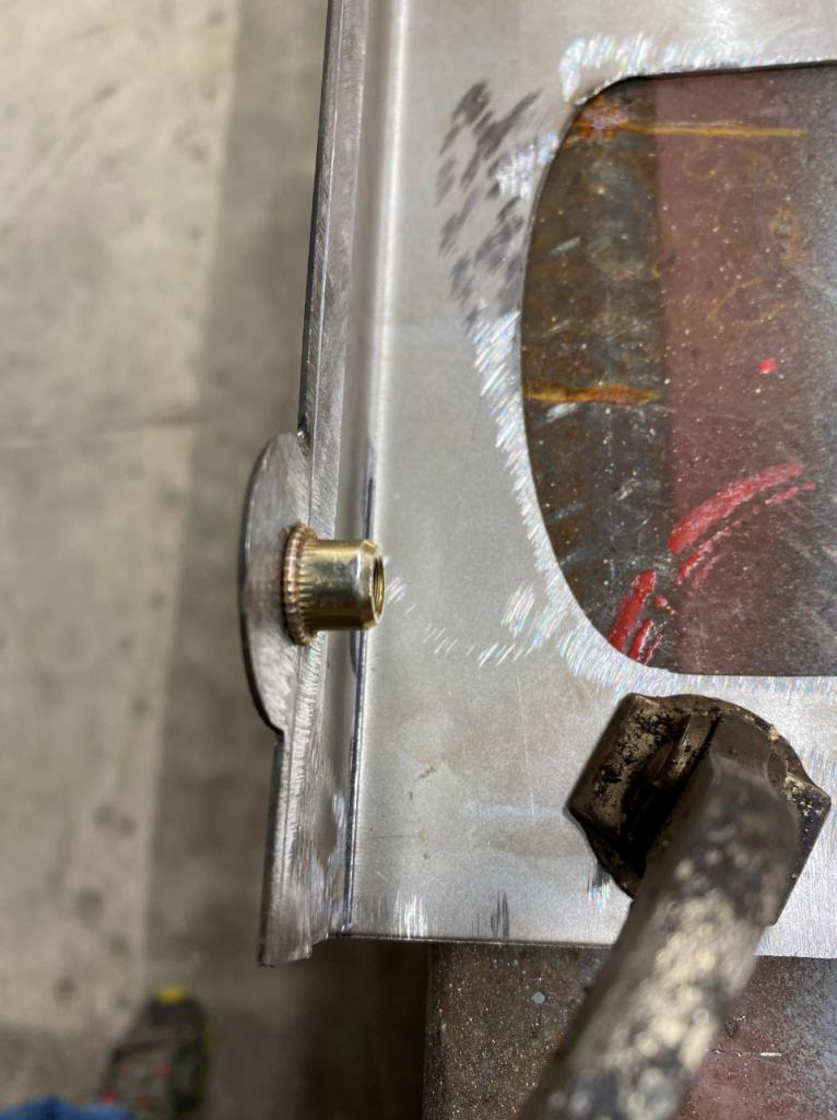
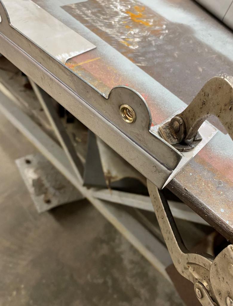
This is what it will look like when open 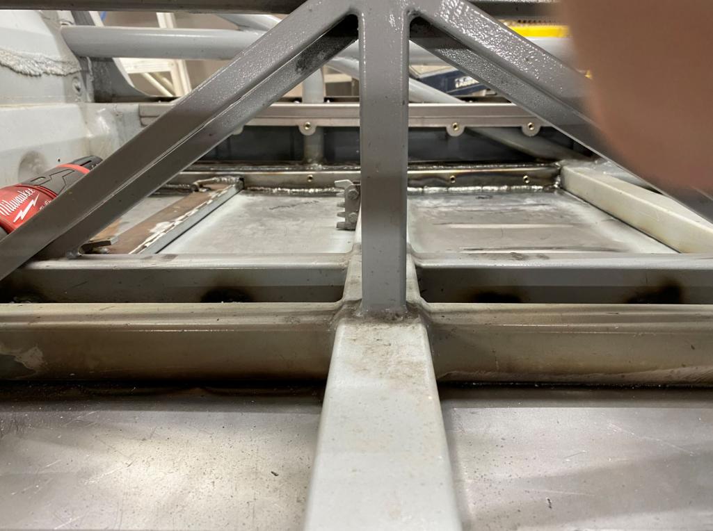
This is closed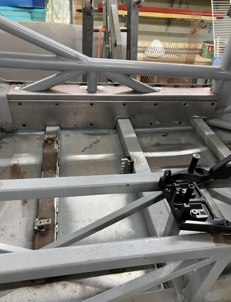
This is top view inside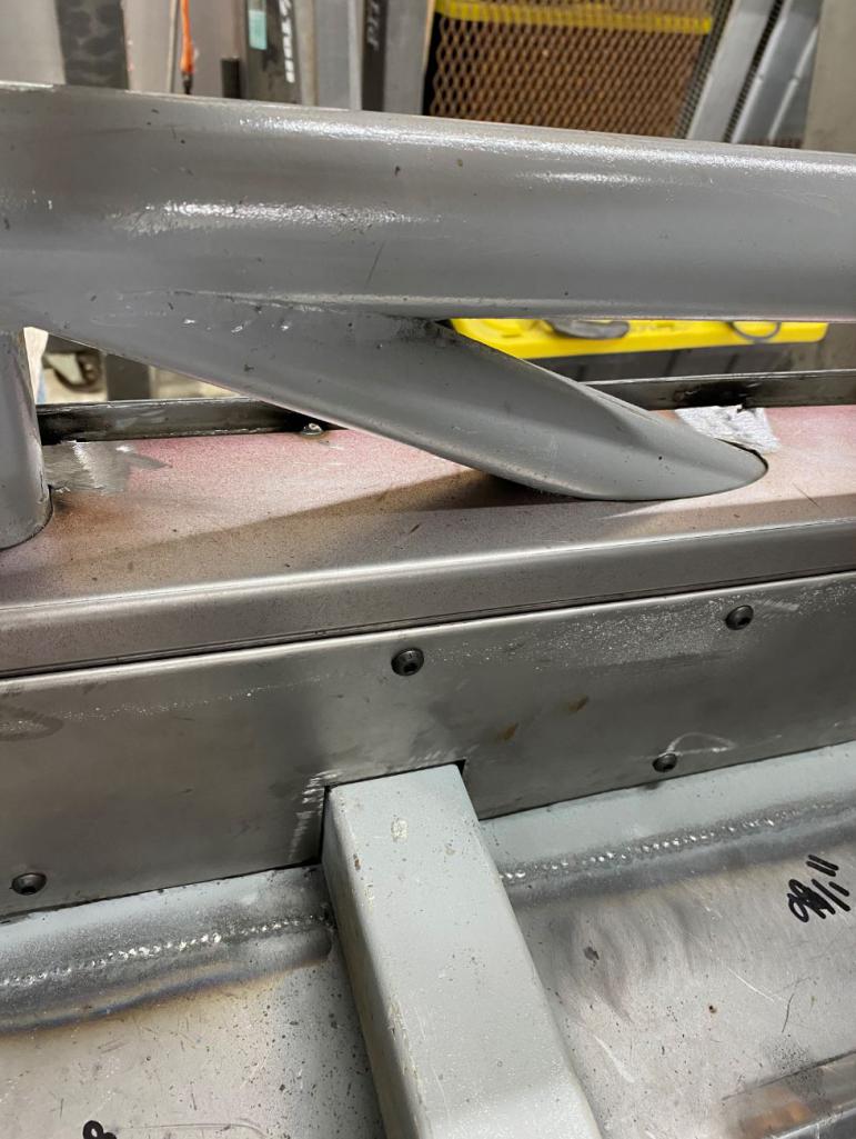
This is top view outside 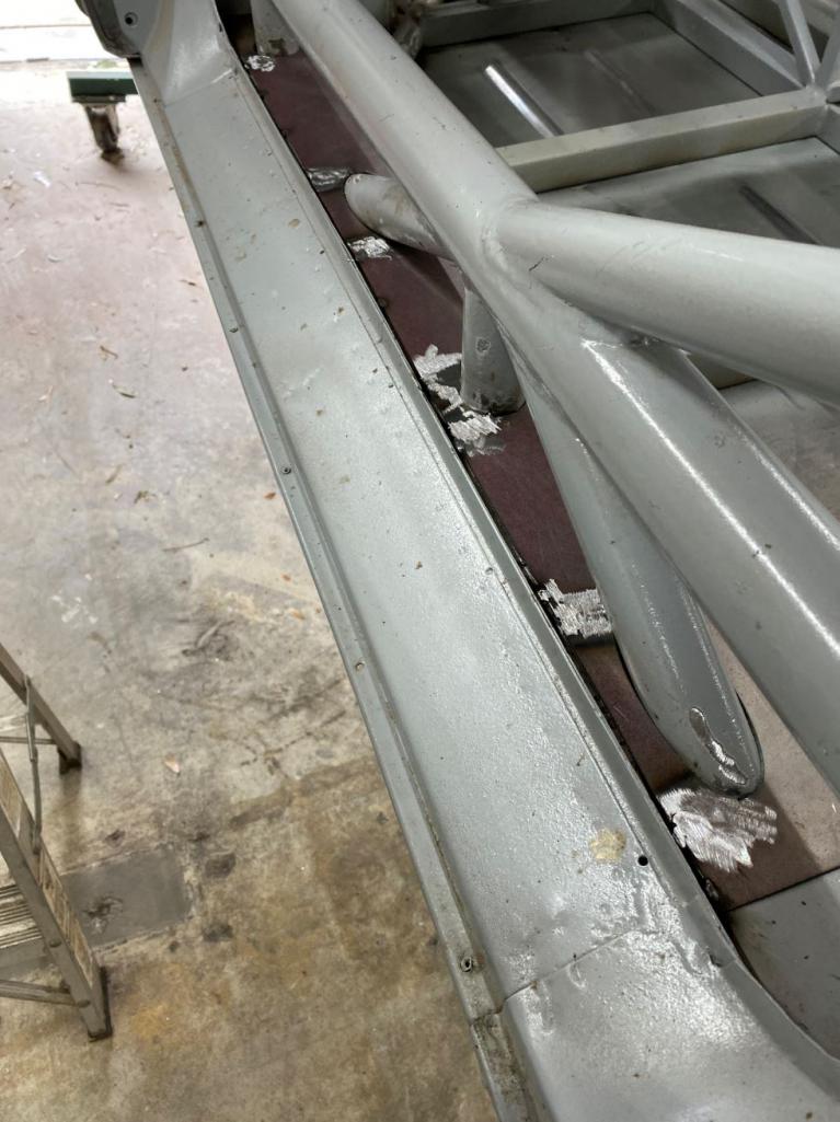
Closing everything up 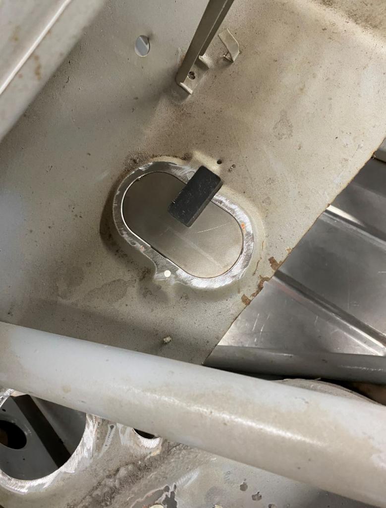
This is what is coming next 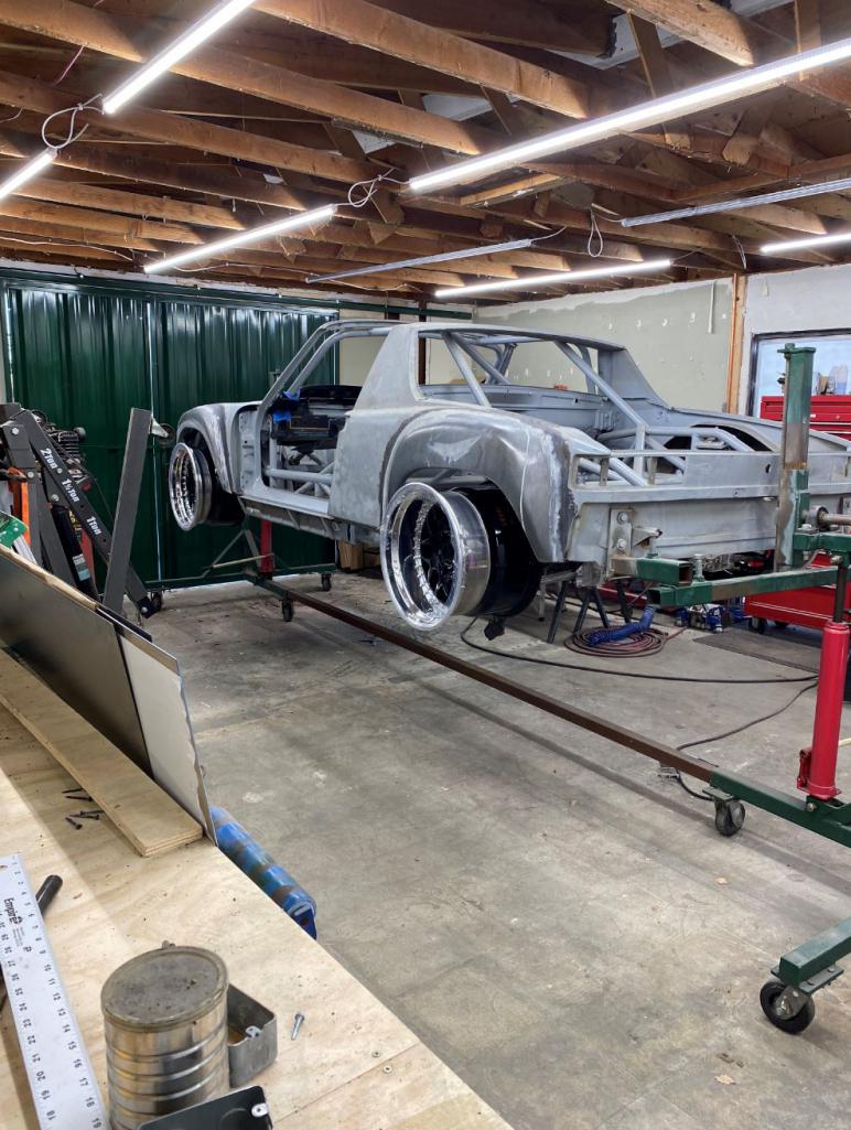
Posted by: ValcoOscar Jan 3 2021, 07:09 PM
Great update Rudy.....
Wishing you and your family a Happy New Year.
Oscar
Posted by: 76-914 Jan 3 2021, 08:03 PM
?Qué bola, Pipo? Wow! You don't post very often but when you do..............you put the rest of us to shame. Amazing work. Your killing it Dude. Can't wait to see this again. Hasta fin de semana.
Posted by: tygaboy Jan 4 2021, 09:50 AM
A plasma table, bead roller and mag brake? Where have I seen that set up before?
Rudy - You're killing it! I love the removable long panels. Very cool design that you brought to life. Great work!
Posted by: Andyrew Jan 4 2021, 04:38 PM
"This is whats coming next"
Holy wheels batman! Just Damn!
Going for the record tire on a street 914??
Posted by: Curbandgutter Jan 5 2021, 12:49 PM
Thanks guys, Happy New Year back @ValcoOscar ,
@76-914 see you this weekend.........no more covid. I will have my new AC system by then. I'm going with a RESTOMOD unit 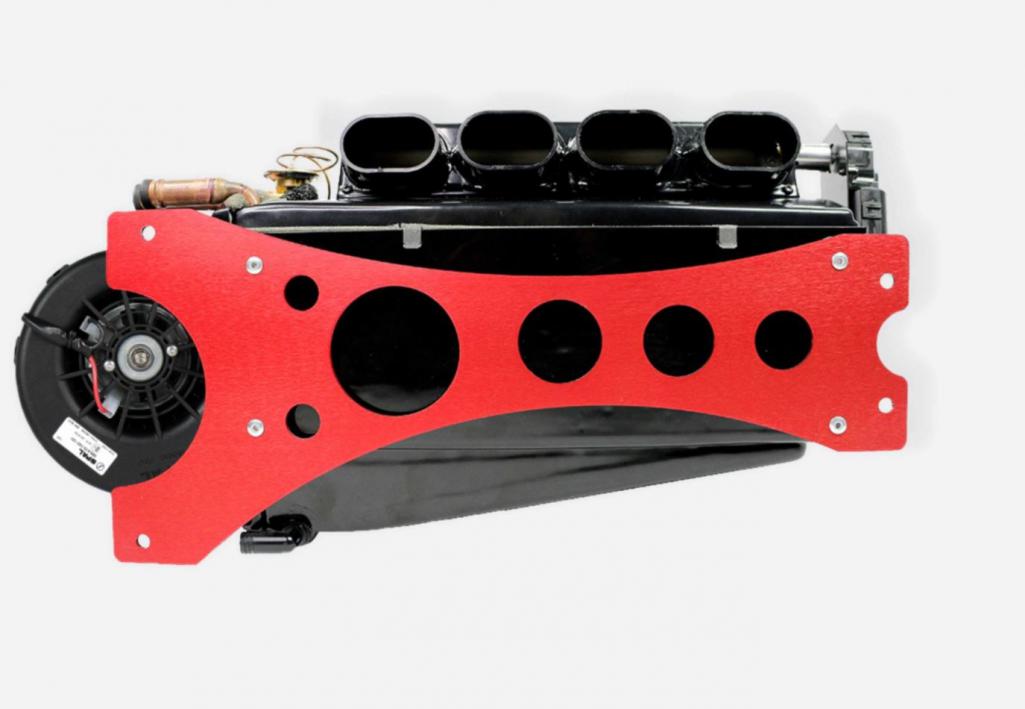
@horizontally-opposed thanks man....I can't wait either.
@tygaboy I don't know...........where? CNC mill and lathe are on backorder  Bought a Precision Matthews 940 mill with Acorn CNC controls, and a Precision Matthews 16x40 lathe. Got something planned for the mill since it has the ability to do 3d contour mapping. Got a little dirty trick planned up my sleeve. You're going to love it.
@Andyrew I don't know if its the record but it will have a 63.5" front track and a 63.0 rear track. 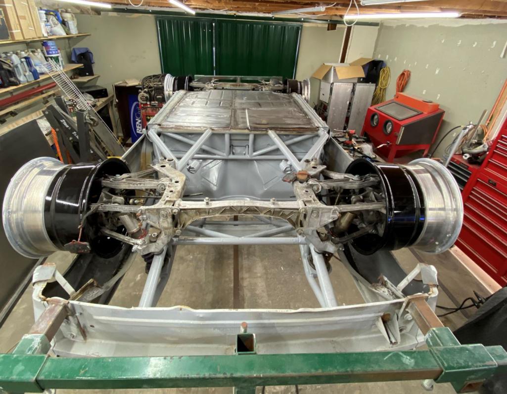
I'm going to flare out the fenders next. Fronts are +4 and rears are +5 over and above what the 916 flare is. 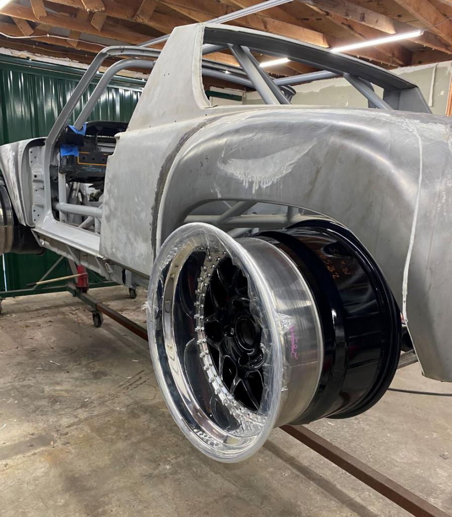
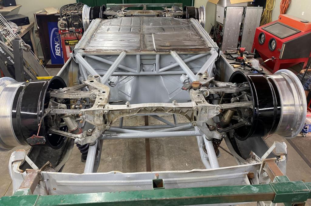
I'm building a jig to keep the fenders in exact location so that when I expand them, they will keep the exact location as the 916 but just wider. I will also extend the curvature transversely along the rear hood. In order to do this I will have to make the face of the fender shrink by about an inch. Can't wait to see it sitting with the new meats and the lengthened wheelbase.
Ohhhhh and pretty soon I will do a twist test to see if I got this thing much stiffer than stock.
Posted by: sb914 Jan 5 2021, 02:42 PM
Wow !
That’s looking “rude” can’t wait to see it!
Hope everything’s going great.
Posted by: Michel Jan 11 2021, 04:37 PM
One of my fave build threads hadn’t seen it awhile . Just finished a morning coffee in downunder oz and got up to speeeed
Posted by: 76-914 Jan 12 2021, 07:12 PM
I just returned from Rudy's and all I can say is be prepared to be awe stricken. IA very humbling experience I must say. I'm not even sure that the trunk lid will remain stock. The welds are impressive as well. Such small, flat "dimes" on thin metal I thought they were TIG welds but they are MIG. Some upcoming metal work will be quiet involved with compound curvatures but I'll stop there and let Rudy reveal when it's time.
Posted by: Tonyooc Jan 12 2021, 07:34 PM
That looks awesome. Can't wait to see the finished product
Posted by: racerbvd Jan 12 2021, 08:14 PM
Incredible.....
Posted by: ClayPerrine Jan 13 2021, 09:21 AM
This is beautiful work.... but I have a question.
Looking at this picture:
I noticed the diagnoal bars on the bottom of the engine compartment. My question is: How are you going to get the engine in the chassis? The inside diagonal bars are in the way of lifting the engine up in to the engine compartment.
Clay
Posted by: 76-914 Jan 13 2021, 09:28 AM
This is beautiful work.... but I have a question.
Looking at this picture:
I noticed the diagnoal bars on the bottom of the engine compartment. My question is: How are you going to get the engine in the chassis? The inside diagonal bars are in the way of lifting the engine up in to the engine compartment.
Clay
The engine drops in from the top. The braces on top are removable, clay.
Posted by: Curbandgutter Jan 14 2021, 01:52 PM
@http://www.914world.com/bbs2/index.php?showuser=9964 Thanks man.......but you're over selling it.........makes it harder to impress. All kidding aside, thanks for the compliment.
I'm moving on to flaring the fenders and making room for intercoolers in the quarter panels. Planning on cutting the 1/4 panel and bending approximately 30 degrees. After I'm done with it, you'll be able to carry luggage in there. It's not going to be a make-believe-vent .
Posted by: mgp4591 Jan 14 2021, 01:58 PM
@http://www.914world.com/bbs2/index.php?showuser=9964
Thanks man.......but you're over selling it.........makes it harder to impress. All kidding aside, thanks for the compliment. I'm moving on to flaring the fenders and making room for intercoolers in the quarter panels. Planning on cutting the 1/4 panel and bending approximately 30 degrees. After I'm done with it, you'll be able to carry luggage in there.
It's not going to be a make-believe-vent .Loading in the luggage into the vent openings??
Posted by: Curbandgutter Jan 14 2021, 02:35 PM
A little look into what the ac system is going to be like
This is a RESTOMOD unit. 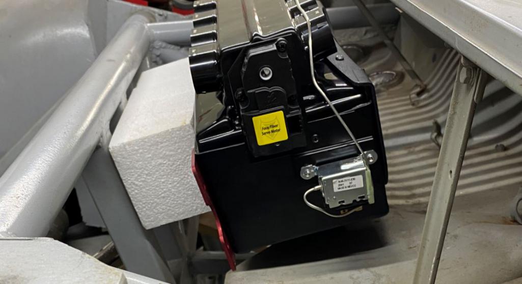
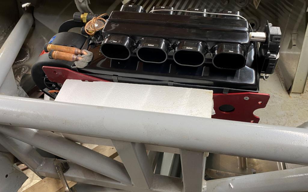
I will be adding aluminum diamond plate in the footwell area. This is my variation of AUTOCardboard.....sometimes I use foamboard.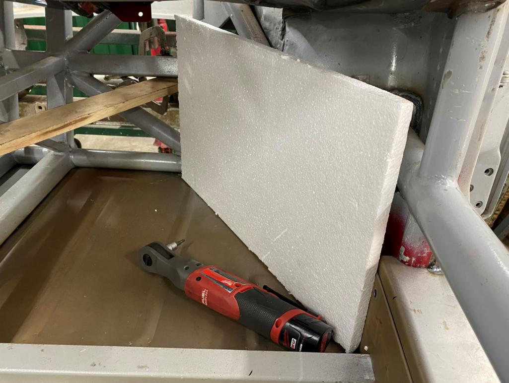
Posted by: ClayPerrine Jan 14 2021, 03:38 PM
I will be adding aluminum diamond plate in the footwell area. This is my variation of AUTOCardboard.....sometimes I use foamboard.
Ah.. another proponent of CAD (Cardboard Aided Design).
Posted by: horizontally-opposed Jan 14 2021, 05:54 PM
A little look into what the ac system is going to be like
This is a RESTOMOD unit.
This thing is super cool. (Sorry, couldn't help myself.)
Do you think it might fit into the stock area in a 914 with a standard fuel tank if the expansion tank and factory fresh air box are removed? Does it get under the cowling?
Posted by: Curbandgutter Jan 14 2021, 07:16 PM
I think it would work. Even if you have to cut the floor of the firewall to lower it say an inch it will fit any 914. Also, it beats anything out there with all the electronics. It's an amazing unit with electric servos. No wires to control air mix. This is infinitely variable mix too. They have the best billet air vents as well. Installed in this fashion it will leave all kinds of legroom. It's the way to go IMHO.
I'm thinking of using this style of vent 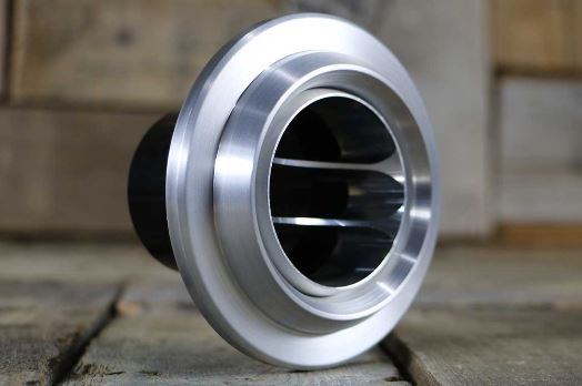
Posted by: 914forme Jan 15 2021, 10:03 AM
A little look into what the ac system is going to be like
This is a RESTOMOD unit.
This thing is super cool. (Sorry, couldn't help myself.)
Do you think it might fit into the stock area in a 914 with a standard fuel tank if the expansion tank and factory fresh air box are removed? Does it get under the cowling?
Simple answer is no, mocked one up a while ago. But if you don't mind a bit of cutting on the separator panel then yes it will fit, have to move the cowl support or build a new one, and it gets in there just fine. Added benefit is the floor heat venting actually works, for pure A/C it does not matter that much. And the wiper mechanism is out of the way if your worried. Lots of room there just not a lot of depth, you have to pull it over to the passenger side as you have steering shaft going into that area also. One thing I was messing with was moving the blower off the unit to gain a bit more in the packaging space. Can't remember if you lost the washer bottle or not, not a big deal, plenty of Modern VAG cars have remote washer bottles with electric pumps that would fit under the gas tank and keep the fill high. All about packaging.
This build it will not be an issue at all.
Keep rocking this one
Posted by: Curbandgutter Feb 1 2021, 07:01 PM
LET THE HAUNCHES BEGIN!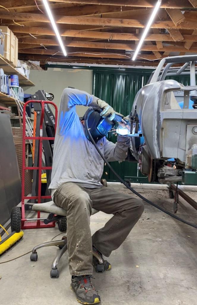
made a jig to keep the fender geometry intact when I cut and pull out 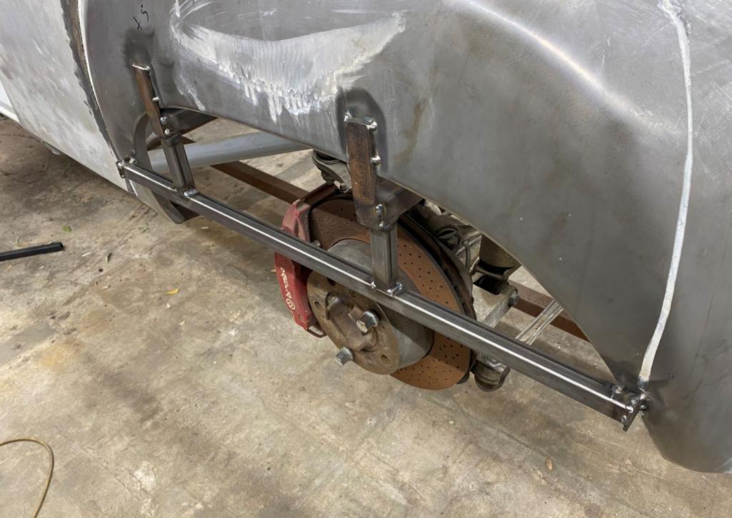
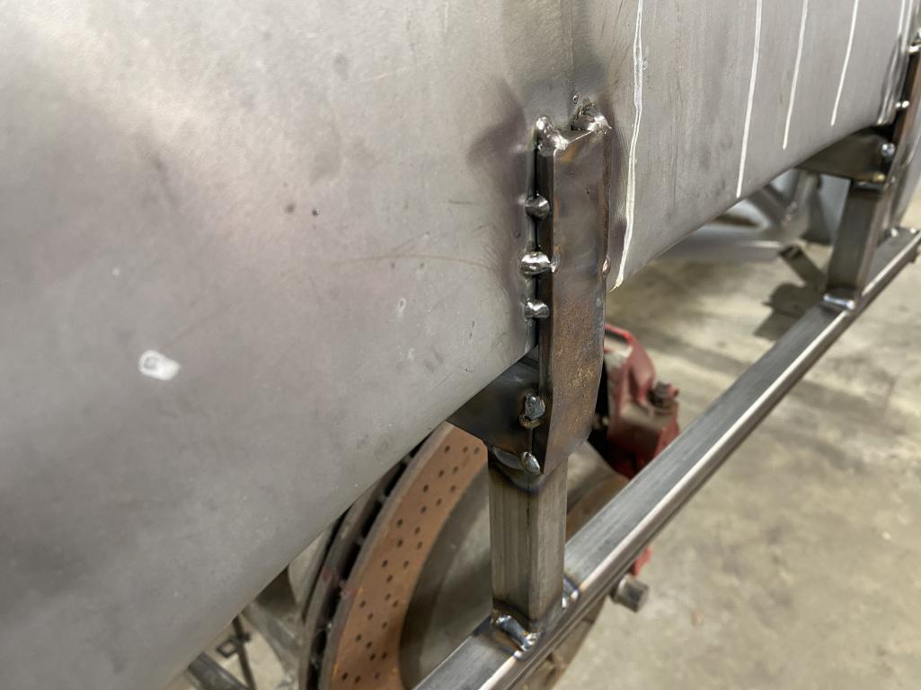
left and right side are attached and in level and parallel plane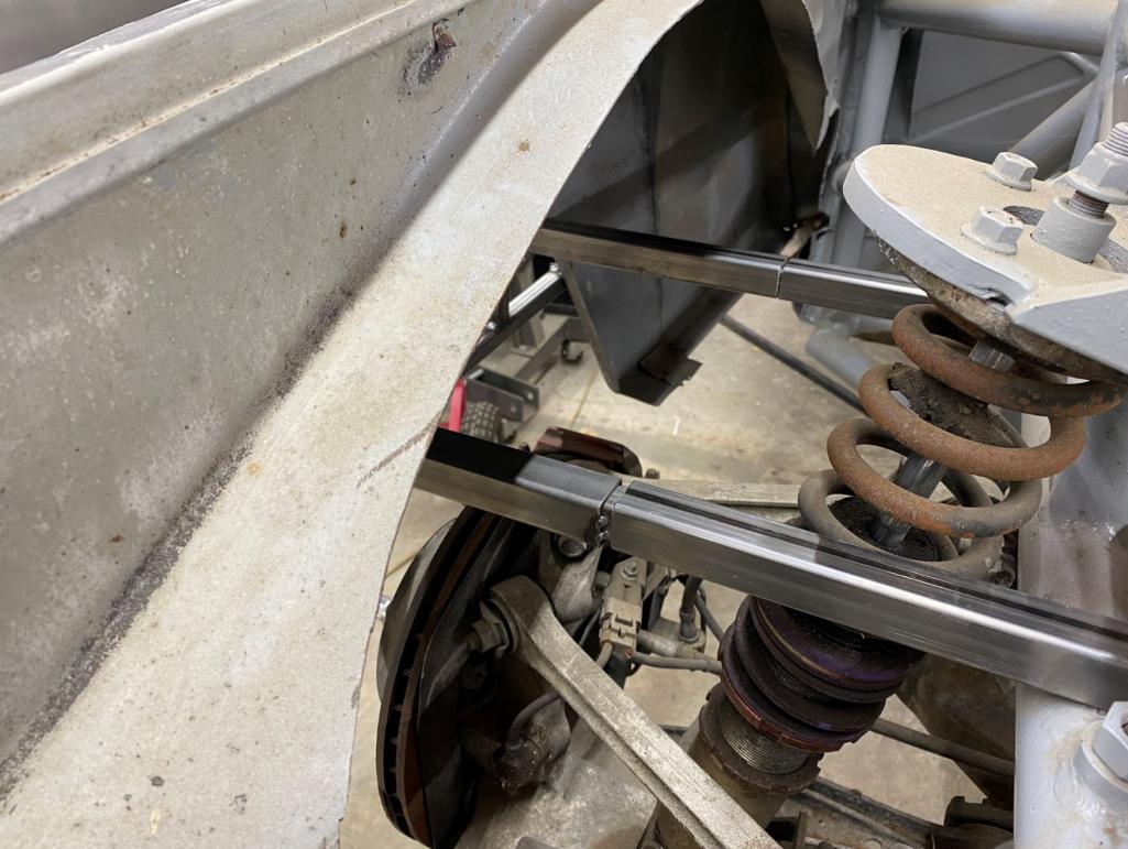
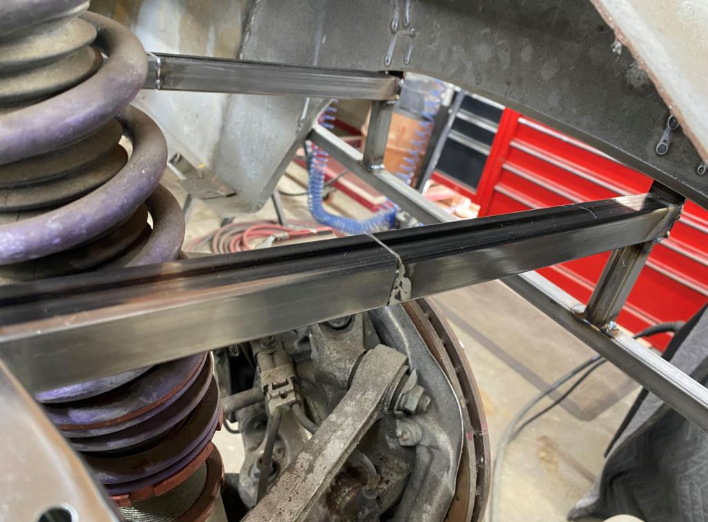
mark and cut 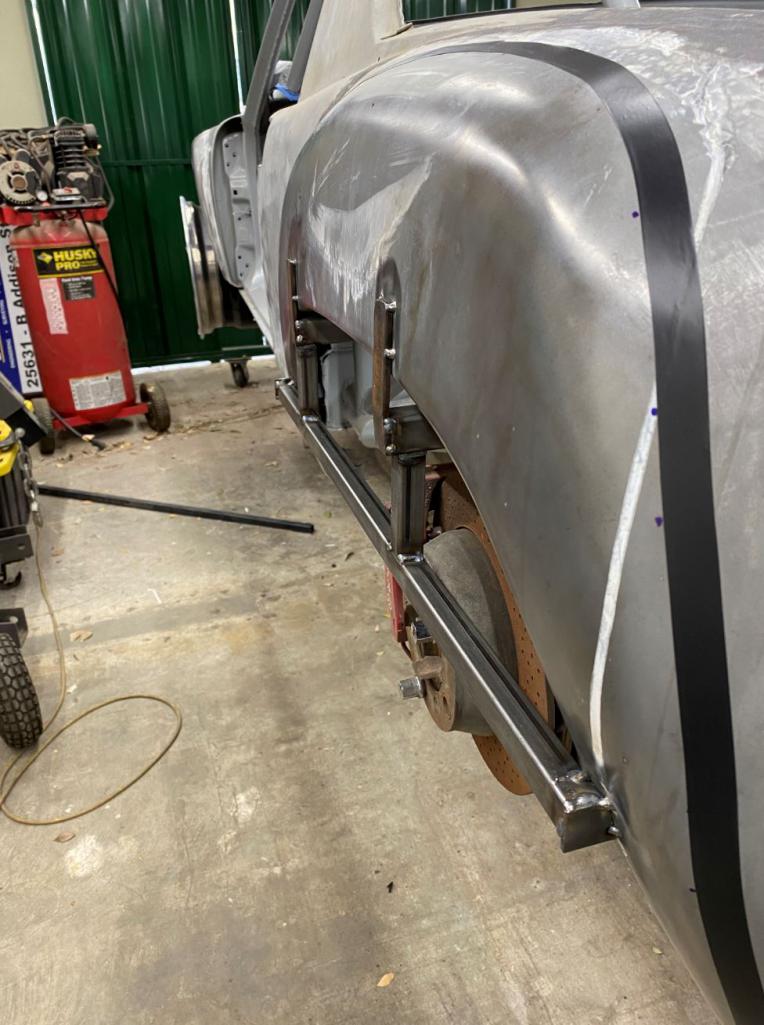
slide out. Notice how much I'm going to drop the top of the fender/ about 3/4" 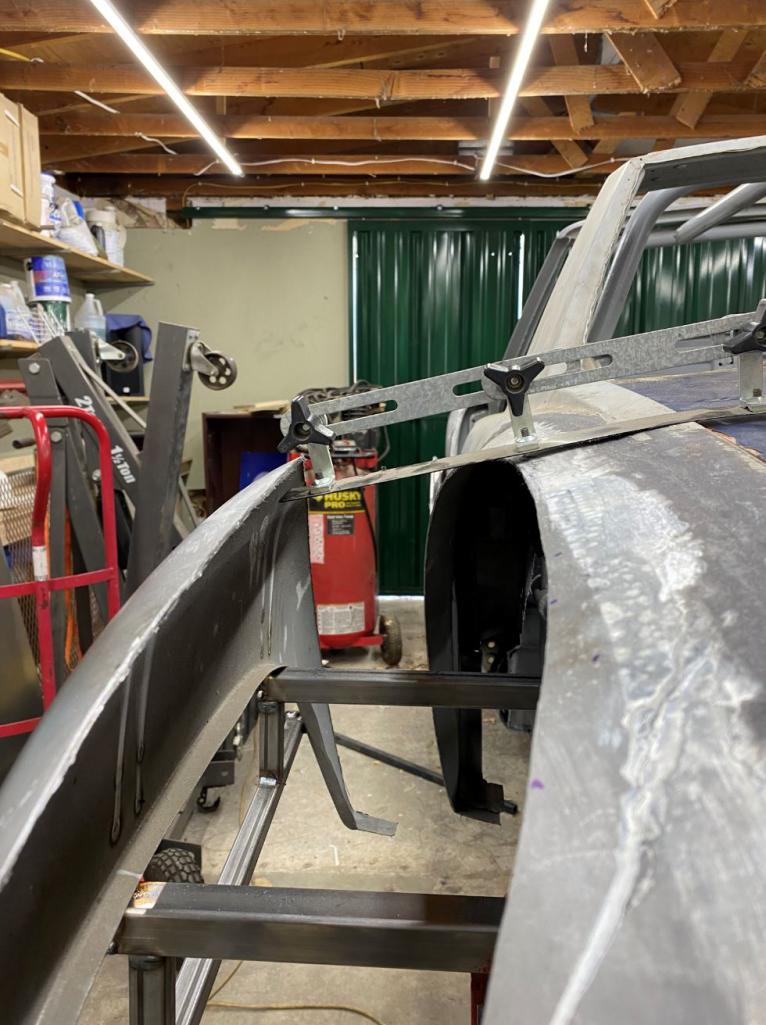
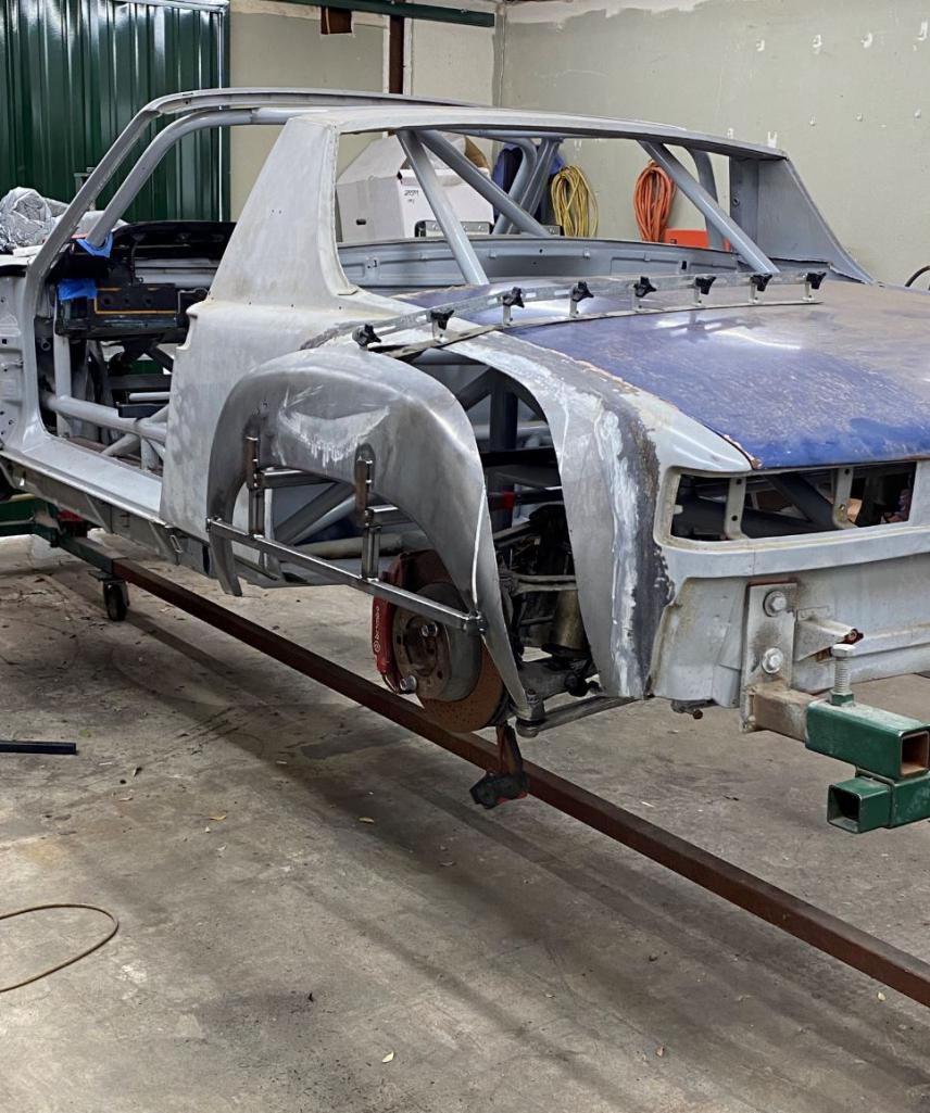
Posted by: 76-914 Feb 1 2021, 08:05 PM
Damn, I wish I had time to see it this week. Maybe next week Pipo. You're moving along quickly. Did you get your lathe yet?
Posted by: Curbandgutter Feb 1 2021, 08:49 PM
Damn, I wish I had time to see it this week. Maybe next week Pipo. You're moving along quickly. Did you get your lathe yet?
Maybe even have my 1/4 panel/luggage holder started. Posted by: pete000 Feb 1 2021, 08:59 PM
Love that fender sliding jig, very nicely done. This build will bring new meaning to the term "Wide Body!"
Posted by: horizontally-opposed Feb 1 2021, 09:25 PM
This project just makes me smiiiiiile.
So cool, and love seeing the creativity!
Posted by: Mueller Feb 3 2021, 11:42 AM
The fixtures for the flare surgery is next level stuff...I dig it.
Posted by: Curbandgutter Feb 5 2021, 12:22 PM
Thanks for all the nice comments. This weekend I plan on owering the fender tops about 1 inch and tying the tops of the fenders together. I plan on using the English wheel to give it that slight arch. Lets see how it goes. ........oh and mill came in today Looks like I'll be making my own suspension pieces.
Posted by: ValcoOscar Feb 5 2021, 12:51 PM
Thanks for all the nice comments. This weekend I plan on owering the fender tops about 1 inch and tying the tops of the fenders together. I plan on using the English wheel to give it that slight arch. Lets see how it goes.
........oh and mill came in today Looks like I'll be making my own suspension pieces. Congrats Rudy-
I see Curbandgutter MotorSports operation in your future
O
Posted by: Curbandgutter Feb 7 2021, 11:07 PM
UPDATE ON REAR FLARES
Mark to cut and slide down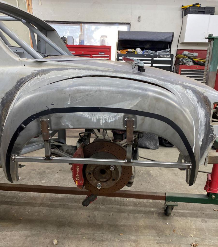
cut and slide down 1 inch 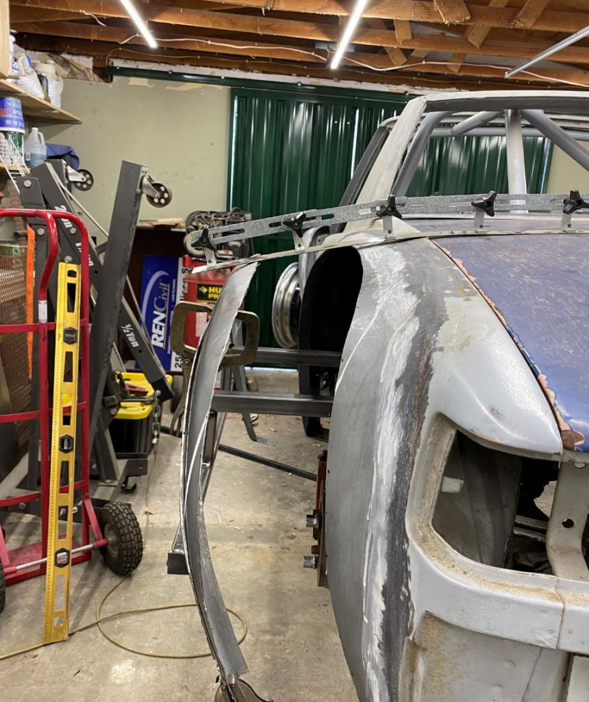
This is how high the edge is prior to lowering 1 inch 
Post lowering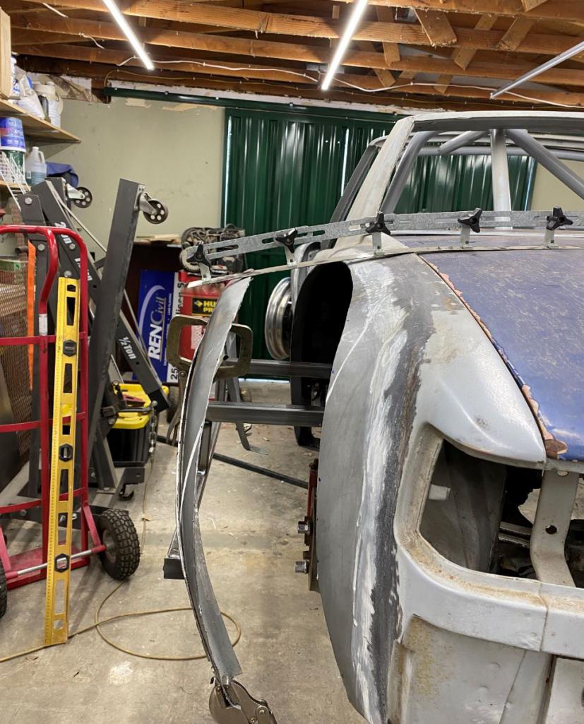
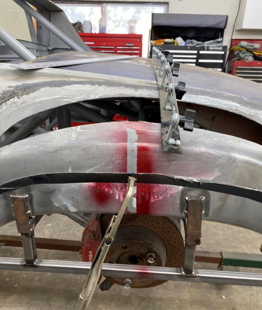
fitting the top piece 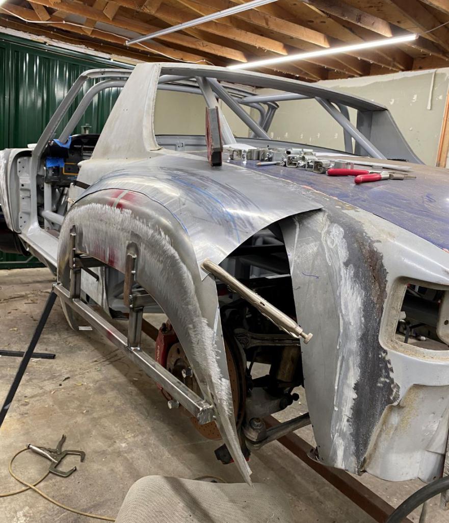
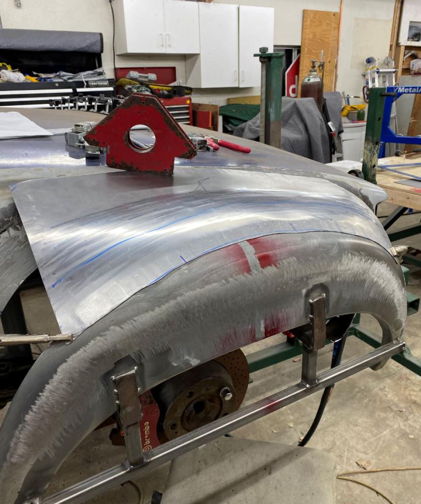
Attached thumbnail(s)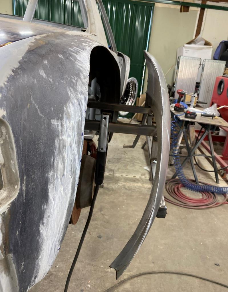
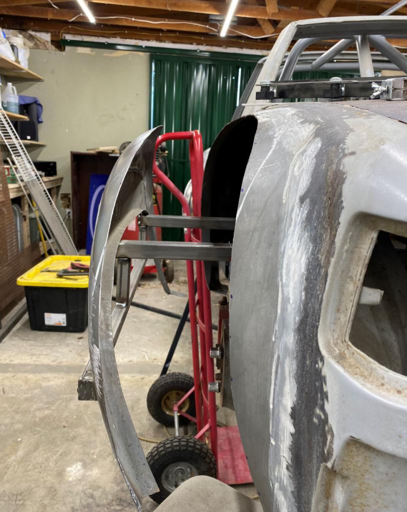
Posted by: Krieger Feb 7 2021, 11:53 PM
Wow! That is going to look incredible!
Posted by: raynekat Feb 8 2021, 01:04 AM
I can't wait to see what these humongous STEEL rear fenders look like when completed. You are certainly a professional mad scientist. Very cool.
Posted by: tygaboy Feb 8 2021, 09:30 AM
Tool Whore's the world over say, "Excellent use of the curvy template tool."
And by the way, it took me 531 days between when I started installing my flares until I fired my car for the first time (March 14, 2019 to August 26, 2020). I don't want to wait that long to see your car run so hopefully, you're a faster fabber than me!
Rudy, your car is gonna be wild! Can't wait to see it.
Posted by: Curbandgutter Feb 8 2021, 12:04 PM
Thanks for all the nice comments. This weekend I plan on owering the fender tops about 1 inch and tying the tops of the fenders together. I plan on using the English wheel to give it that slight arch. Lets see how it goes.
........oh and mill came in today Looks like I'll be making my own suspension pieces. Congrats Rudy-
I see Curbandgutter MotorSports operation in your future
O
I'm just loading up with tools so that I have them when I retire in about 10 years.
Posted by: Andyrew Feb 8 2021, 12:56 PM
Damn, That sectioning of the rear flare is some damn fancy work! I didnt even see it the first time I looked at the pics! I thought it was just mockup!! The English wheel work is also fabulous!
Posted by: Curbandgutter Feb 8 2021, 01:43 PM
Hey this is what I'm thinking for the rear. I'm open to suggestions.
I'm thinking of something like this. It's hard to illustrate it, but it won't look like horns or cat eyes. I'm thinking of 3d printing the louvers and then dipping in that paint that makes it look like carbon fiber. Where it attaches to the rea by the light will follow the contour of the fender 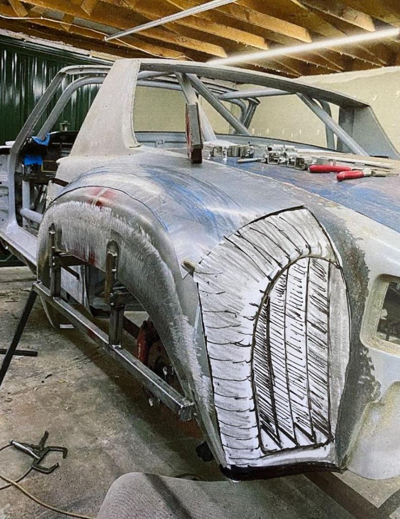
do nothing 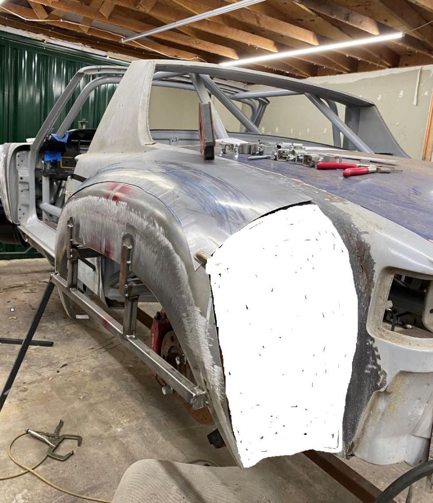
Attached thumbnail(s)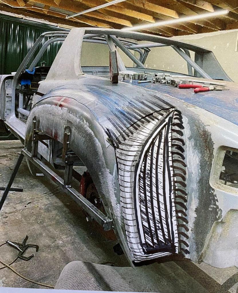
Posted by: Curbandgutter Feb 8 2021, 02:10 PM
Damn, That sectioning of the rear flare is some damn fancy work! I didnt even see it the first time I looked at the pics! I thought it was just mockup!! The English wheel work is also fabulous!
Thanks Andrew. It's really not that bas once you understand how the metal behaves. It's like thinning out pizza dough.
Posted by: Andyrew Feb 8 2021, 02:17 PM
I say you get the fender done, put a tire under it and see how it looks.
What other things are you doing to the rear that is non standard? Having these vents will help performance wise but its going to look really odd on this car if nothing else "modern" is being done besides wheels (And obviously the whole chassis but thats not visible from the outside).
DO you prefer form or function here?
There is a lot of trapped air in the back of a 914, but if for example you use a diffuser, there likely wont be much at all. And there is so little area behind the 914 rear tire that there wont be much air flowing into it.
Posted by: ClayPerrine Feb 8 2021, 02:22 PM
If you are putting the vents in the rear of the flares, then put a boxster radiator in each one. That way you don't have to run the plumbing up front.
Posted by: Curbandgutter Feb 8 2021, 03:09 PM
I say you get the fender done, put a tire under it and see how it looks.
What other things are you doing to the rear that is non standard? Having these vents will help performance wise but its going to look really odd on this car if nothing else "modern" is being done besides wheels (And obviously the whole chassis but thats not visible from the outside).
DO you prefer form or function here?
There is a lot of trapped air in the back of a 914, but if for example you use a diffuser, there likely wont be much at all. And there is so little area behind the 914 rear tire that there wont be much air flowing into it.
Andrew I'm cutting in a vent opening in the 1/4 panel.......my pseudo luggage rack
, this will bring air into the intercoolers and so I need an exhaust. So, yes, there will be a lot of air in the wheel well. As for the diffuser yes I'm making one that doubles as the stiffening panel along the entire engine bay bottom. I'm using it to tie everything together structurally along the bottom and then doubling as a diffuser. Thinking of going with 1/8" aluminum plate. The diffuser fins will be maybe 20 gauge aluminum that is bolted on to the diffuser with some button head screws. That way they can easily be replaced when needed. I have 6 points of attachment made for that in the cage. I want to modernize the look of the car without going too far........maybe I already did but........I'm planning on using chrome bumpers but modernizing. I've good some ideas ruminating.
Posted by: Curbandgutter Feb 8 2021, 04:20 PM
If you are putting the vents in the rear of the flares, then put a boxster radiator in each one. That way you don't have to run the plumbing up front.
Clay, I will have radiators in front of the wheel. I have 1/4 cut-outs coming!
Posted by: Curbandgutter Feb 8 2021, 04:40 PM
Tool Whore's the world over say, "Excellent use of the curvy template tool."
And by the way, it took me 531 days between when I started installing my flares until I fired my car for the first time (March 14, 2019 to August 26, 2020). I don't want to wait that long to see your car run so hopefully, you're a faster fabber than me!
Rudy, your car is gonna be wild! Can't wait to see it.
Yes......tool whores unite!!!!
I don't know about that 531 days though......We sold our house and I will eventually stop working on project since I'll be building a new house with a real shop. The escrow is a long 6 month to 1 year process so, Ill try and get most of the work done so that I can get car into roller shape so I can transport. First thing to build on the house is the workshop though.
Posted by: Cracker Feb 8 2021, 05:59 PM
Rudy: Your car is going to make a Group 5 look tame by comparison...!
Posted by: tygaboy Feb 8 2021, 07:16 PM
Hey this is what I'm thinking for the rear. I'm open to suggestions.
Above bolding added by me.
Rudy - Take it from me: based on my hood vent posts, whatever you do, DO NOT get the Peanut Gallery fired up about design suggestions!
My suggestion is: Do whatever the hell makes you smile and screw the rest of us!
Posted by: horizontally-opposed Feb 8 2021, 10:32 PM
Rudy - Take it from me: based on my hood vent posts, whatever you do, DO NOT get the Peanut Gallery fired up about design suggestions!
Posted by: Curbandgutter Feb 9 2021, 03:16 PM
Rudy: Your car is going to make a Group 5 look tame by comparison...!
right on!
Posted by: Curbandgutter Feb 9 2021, 03:17 PM
Hey this is what I'm thinking for the rear. I'm open to suggestions.
Above bolding added by me.
Rudy - Take it from me: based on my hood vent posts, whatever you do, DO NOT get the Peanut Gallery fired up about design suggestions!
My suggestion is: Do whatever the hell makes you smile and screw the rest of us!
WILL DO
Posted by: Curbandgutter Feb 11 2021, 11:35 AM
ON TO THE QUARTER PANEL
This is the direction that I'm going with to cut in the 1/4 panel to couch the air to water intercoolers as well as the cold air intakes. The cut will taper from o" depth at the door to 12" depth at the back. Notice how the top cut line is not level, it actually tapers up to follow that ever so slight rise in the 914 silhouette. The bottom line is parallel with the rocker panel.
By the way does anyone know how tall those Porsche side panel stickers are? The ones that go along the bottom of the door. I need a pair but in the negative. I'm thinking of dark metallic charcoal grey for the entirety of the car and then spraying the Porsche sticker logo in a Carrera silver along the bottom of the doors, like the stickers. I may continue that silver into the intake at the 1/4 panels. The rockers will be in black and they will follow the silhouette of the fenders.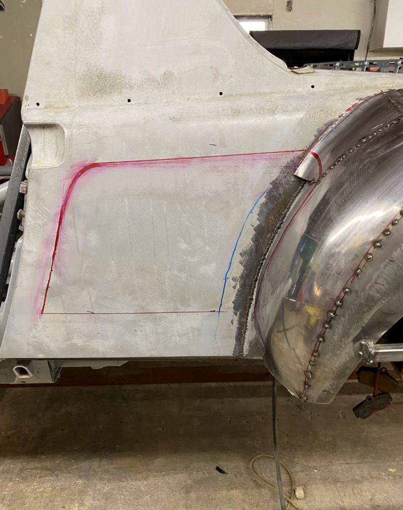
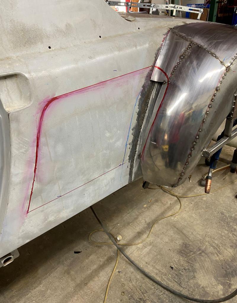
Posted by: jd74914 Feb 11 2021, 01:55 PM
Looking awesome!!
When you say 12" depth at the back is that measured off the OEM quarter panel or from the corresponding point on your flares? Asking since it looks like the heat exchangers will be in the wheel wells.
Posted by: Curbandgutter Feb 11 2021, 02:08 PM
Looking awesome!!
When you say 12" depth at the back is that measured off the OEM quarter panel or from the corresponding point on your flares? Asking since it looks like the heat exchangers will be in the wheel wells.
From the OEM 1/4 panel. The heat exchangers will not be in the wheel wells.
Posted by: ValcoOscar Feb 11 2021, 02:48 PM
ON TO THE QUARTER PANEL
This is the direction that I'm going with to cut in the 1/4 panel to couch the air to water intercoolers as well as the cold air intakes. The cut will taper from o" depth at the door to 12" depth at the back. Notice how the top cut line is not level, it actually tapers up to follow that ever so slight rise in the 914 silhouette. The bottom line is parallel with the rocker panel.
By the way does anyone know how tall those Porsche side panel stickers are? The ones that go along the bottom of the door. I need a pair but in the negative. I'm thinking of dark metallic charcoal grey for the entirety of the car and then spraying the Porsche sticker logo in a Carrera silver along the bottom of the doors, like the stickers. I may continue that silver into the intake at the 1/4 panels. The rockers will be in black and they will follow the silhouette of the fenders.
Hey Rudy, here are my dark silver side panel decals on Chucky
~ $70 (set)
O
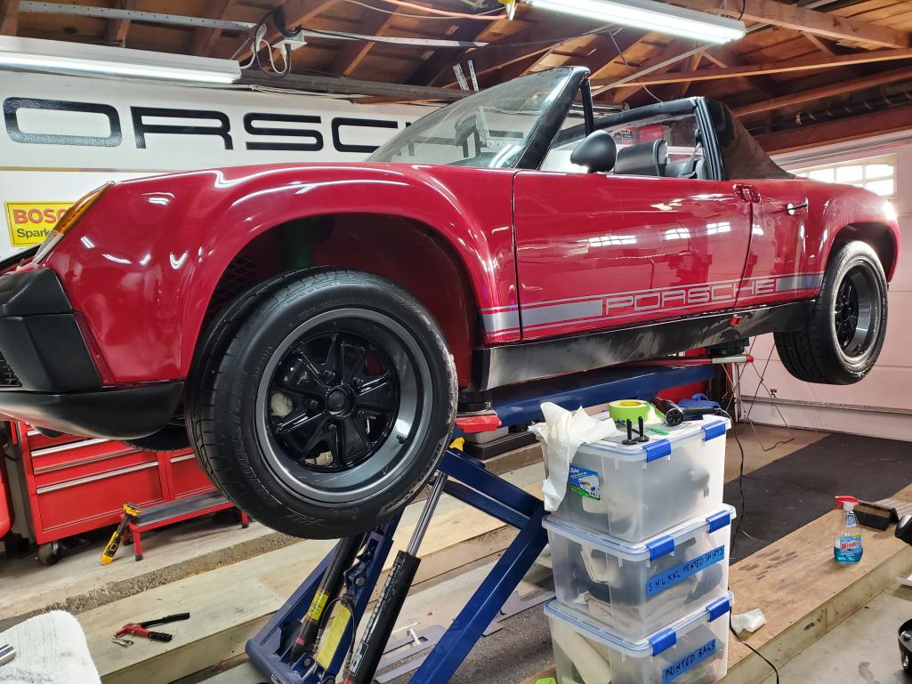
Posted by: Curbandgutter Feb 11 2021, 03:38 PM
<b>@http://www.914world.com/bbs2/index.php?showuser=16669 </b> that's what I'm looking for. But I need the silver part to be open. I would use the sticker to spray the silver portion onto the car then pull the sticker off. How tall is the sticker? I need to know so that I don't cut the 1/4 panel too tall. By the way what is Chucky's. I google it and all I get is the chucky doll.
Posted by: ValcoOscar Feb 11 2021, 03:45 PM
Oscar that's what I'm looking for. But I need the silver part to be open. I would use the sticker to spray the silver portion onto the car then pull the sticker off. How tall is the sticker? I need to know so that I don't cut the 1/4 panel to tall. By the way what is Chucky's. I google it and all I get is the chucky doll.
I will get you height later today, Chucky is my latest 914, LSV8 powered.
But next to your car I may have to rename it Barney
O
Posted by: Curbandgutter Feb 11 2021, 03:46 PM
Oscar that's what I'm looking for. But I need the silver part to be open. I would use the sticker to spray the silver portion onto the car then pull the sticker off. How tall is the sticker? I need to know so that I don't cut the 1/4 panel to tall. By the way what is Chucky's. I google it and all I get is the chucky doll.
I will get you height later today, Chucky is my latest 914, LSV8 powered.
But next to your car I may have to rename it Barney
O
OK....by the way...that Chucky is one bad looking ride. Posted by: ValcoOscar Feb 11 2021, 03:59 PM
Oscar that's what I'm looking for. But I need the silver part to be open. I would use the sticker to spray the silver portion onto the car then pull the sticker off. How tall is the sticker? I need to know so that I don't cut the 1/4 panel to tall. By the way what is Chucky's. I google it and all I get is the chucky doll.
I will get you height later today, Chucky is my latest 914, LSV8 powered.
But next to your car I may have to rename it Barney
O
OK....by the way...that Chucky is one bad looking ride. Thx
I have these coming in dark silver as a back up.
Not sure if I'll swap out
O
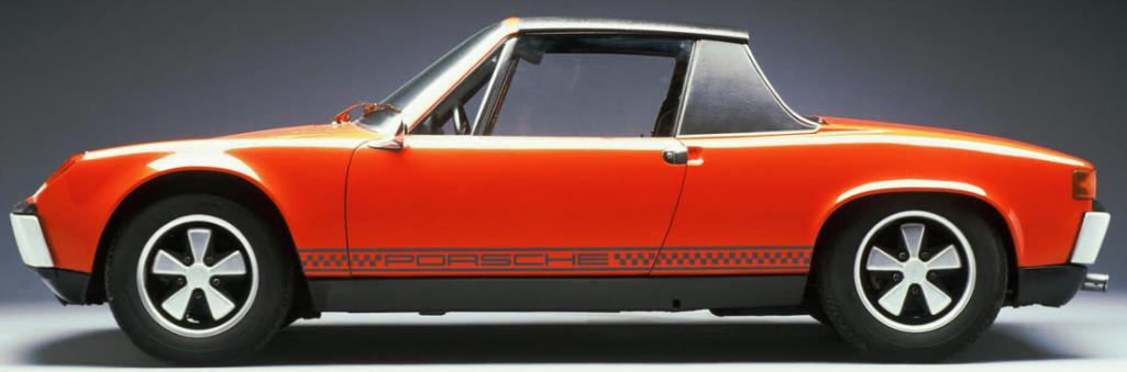
Posted by: ValcoOscar Feb 12 2021, 09:33 AM
Hey Rudy
My side decals measure 3.00 tall
@http://www.914world.com/bbs2/index.php?showuser=15637
0
Posted by: Curbandgutter Feb 12 2021, 11:33 AM
Hey Rudy
My side decals measure 3.00 tall
@http://www.914world.com/bbs2/index.php?showuser=15637
0
Thanks bud. I gave myself 4" so I'm free and clear to cut in.
Posted by: Curbandgutter Feb 13 2021, 04:47 PM
LEFT REAR PRETTY COMPLETE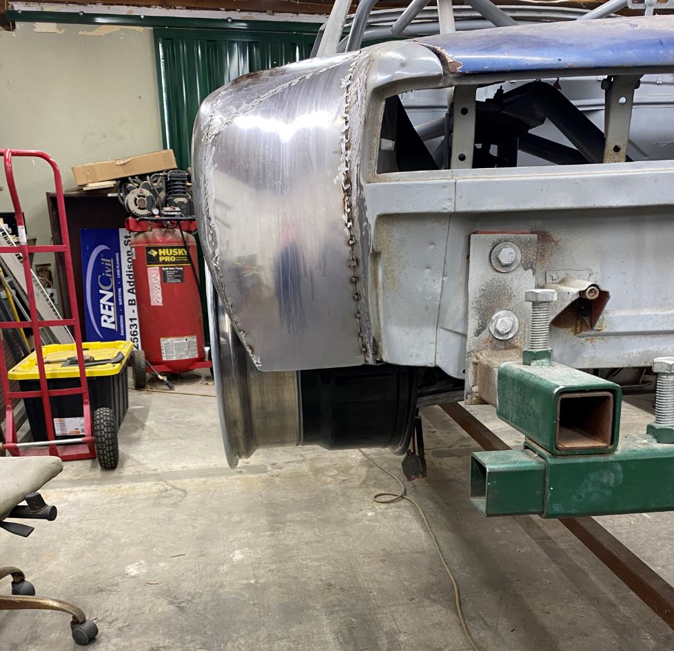
INSERT SUIT CASE HERE 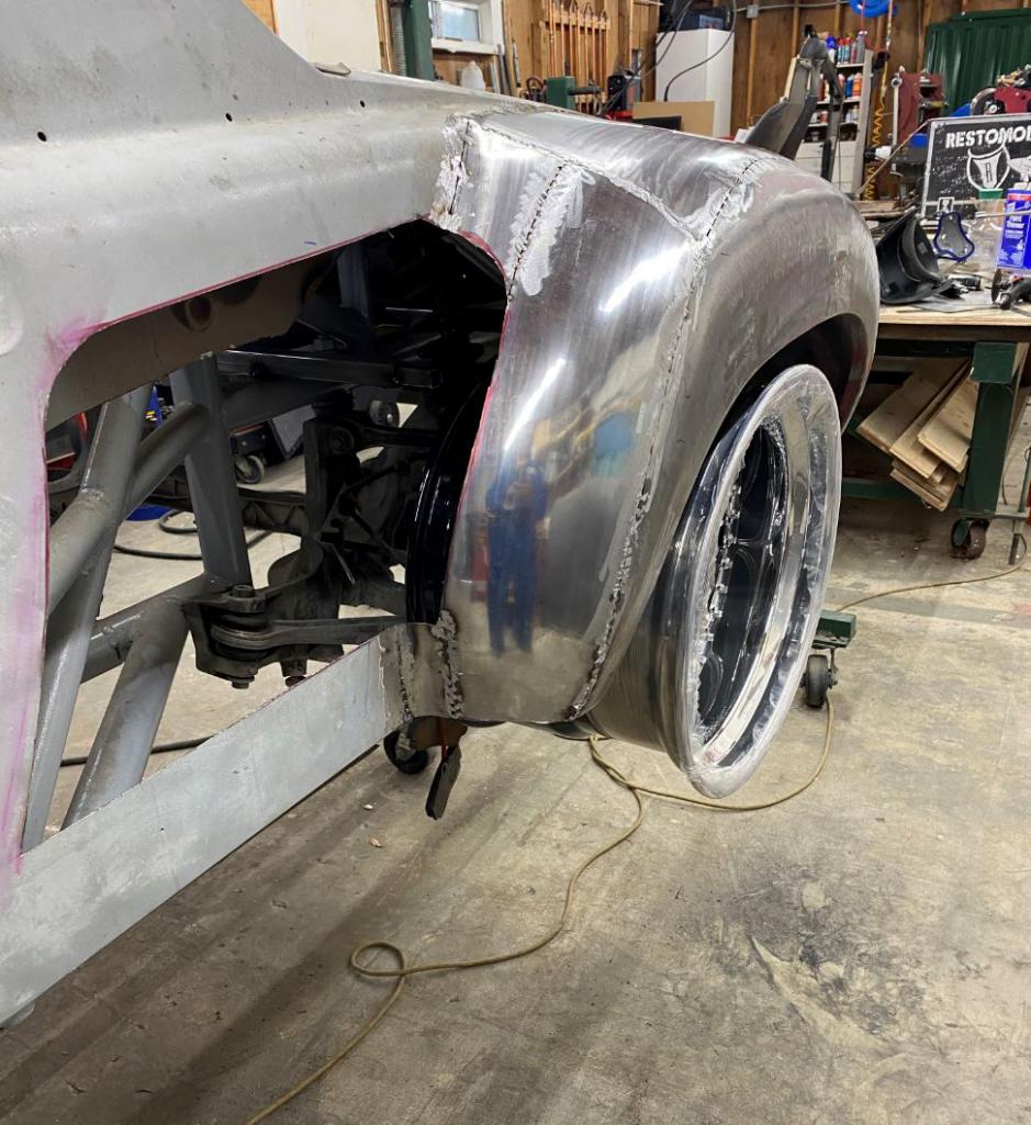
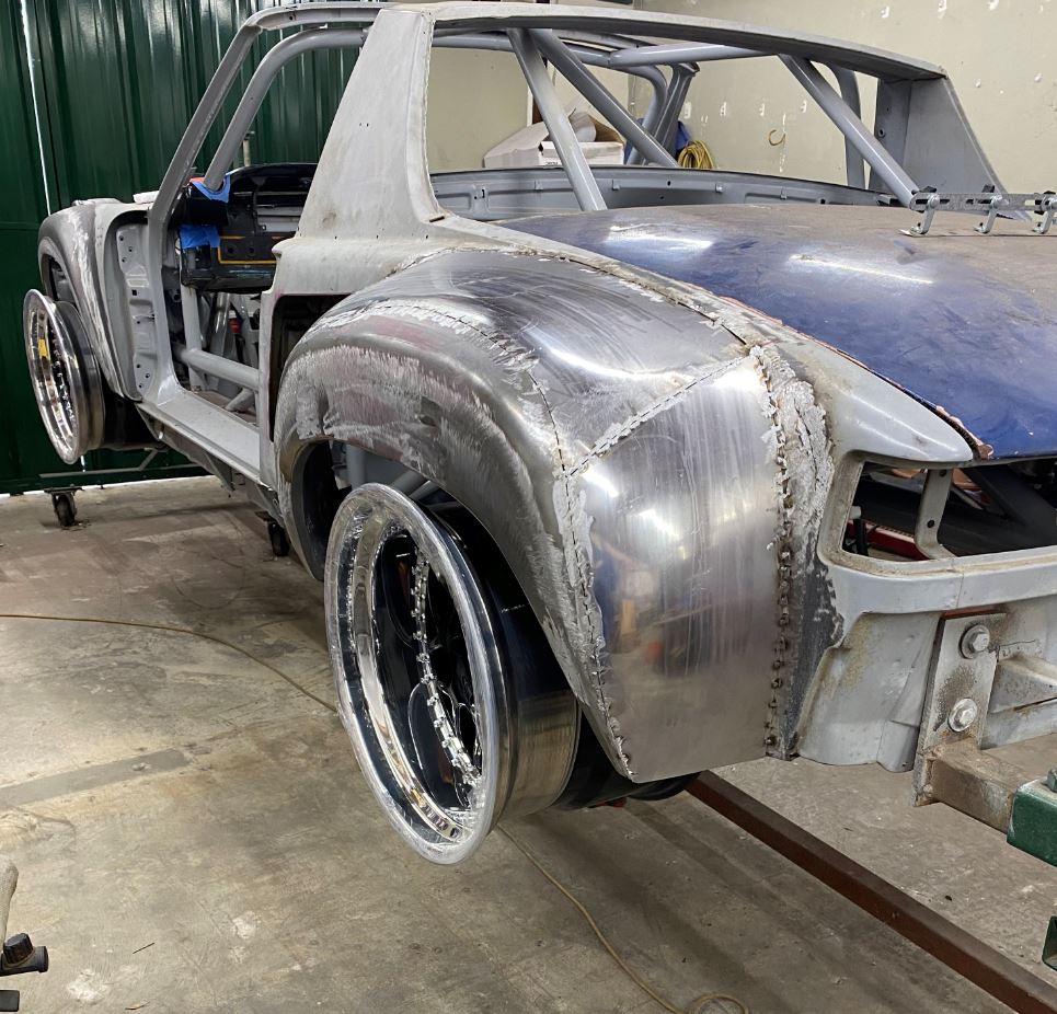
Posted by: sixnotfour Feb 13 2021, 05:46 PM
you should jack the wheel to stance position... :trophy:
Posted by: Andyrew Feb 13 2021, 11:09 PM
That's looking really awesome!!! Keep at it!!!
Are you making a wood buck or two for the pass side?
Posted by: 76-914 Feb 14 2021, 08:09 PM
I dropped by Rudy's yesterday and checked out his build. It's on another level entirely. His shop is a fabricators dream and what impresses me is he knows how to use all of that equipment. I watched him program a pattern on his computer with a CAD program then transfer it to the computer on his plasma cutting machine. I'm pretty sure it would take me about 11 years just to master what he did in under an hour. I think his decision to go back with the Audi drivetrain is a smart move even though the LS is a popular power plant. This build with the combination of the Audi drivetrain and super wide trac and huge tires should be a rocket off the line and insane through the turns.
Posted by: erwan914 Feb 22 2021, 02:46 AM
Fitment check.......they finally arrived!
hello
what is the brand of your rims?
Posted by: Curbandgutter Feb 22 2021, 09:43 PM
Fitment check.......they finally arrived!
hello
what is the brand of your rims?
FORGESTAR
Posted by: Curbandgutter Feb 22 2021, 09:45 PM
REAR FENDERS ARE PRETTY COMPLETE NOW. RUBBER COMING IN TOMORROW. JOPING TO START FRONT FENDERS THIS WEEKEND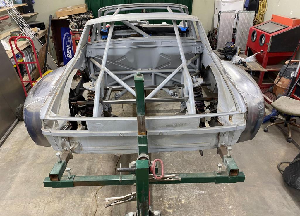
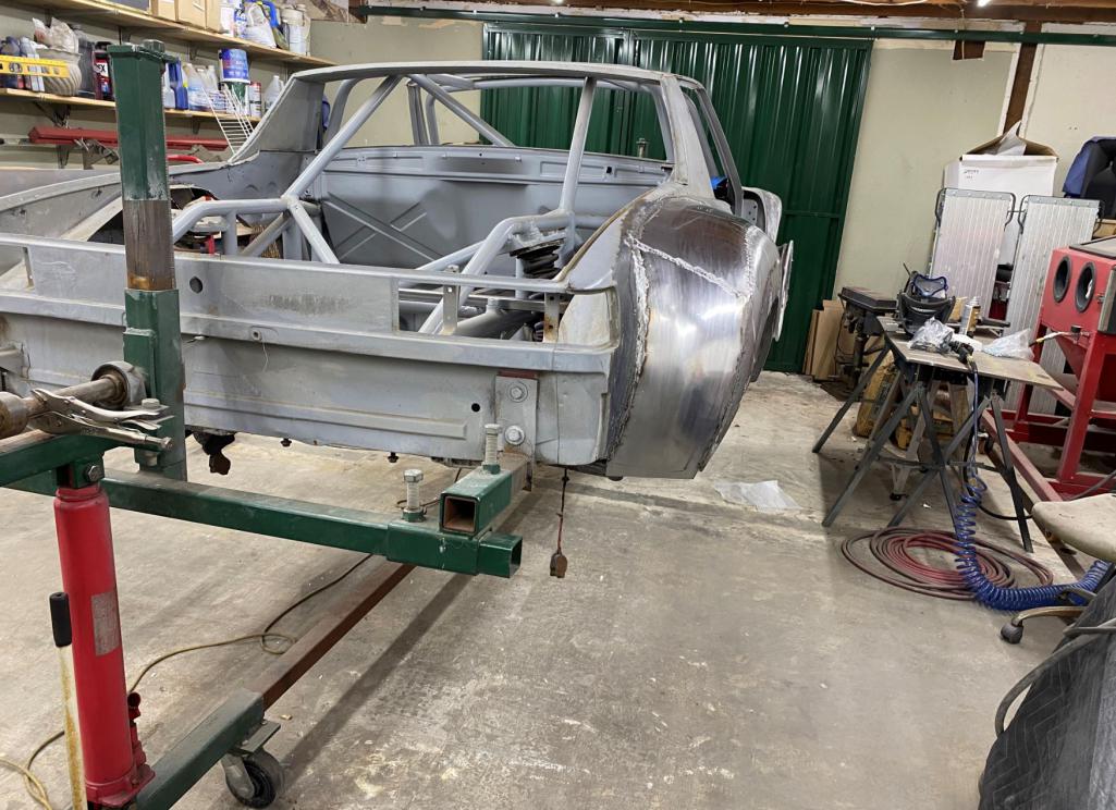
Posted by: Curbandgutter Feb 23 2021, 04:49 PM
Hey does anyone have front portions of the front fenders available? I need the portion where the turn signal bucket goes in. I want to widen the front turn signal bucket about 1" so that I can stick some LED's in there. Since I will be working the front fenders this weekend.......timing will be just right.
Posted by: Rand Feb 23 2021, 09:48 PM
Totally awesome build. Huge props.
I have to ask... is that driver's side cage tube gonna be a head knocker? Seems low and right in line with a helmet. Sorry, don't mean to be negative at all, pic just begged the question.
Outstanding metalwork.
Posted by: Jeff Hail Feb 24 2021, 02:37 AM
Hey does anyone have front portions of the front fenders available? I need the portion where the turn signal bucket goes in. I want to widen the front turn signal bucket about 1" so that I can stick some LED's in there. Since I will be working the front fenders this weekend.......timing will be just right.
Why not just slit the fenders right down the crown from the middle of the turn signal bucket? A lot easier to work with the original shape intact and one cut on the top.
Posted by: Andyrew Feb 24 2021, 08:05 AM
Totally awesome build. Huge props.
I have to ask... is that driver's side cage tube gonna be a head knocker? Seems low and right in line with a helmet. Sorry, don't mean to be negative at all, pic just begged the question.
Outstanding metalwork.
Rudy mentioned on facebook that he's going to remove the A to B pillar bars after he's done with chassis work, they were there just to keep the chassis straight during fab.
Posted by: Curbandgutter Feb 24 2021, 11:53 AM
Hey does anyone have front portions of the front fenders available? I need the portion where the turn signal bucket goes in. I want to widen the front turn signal bucket about 1" so that I can stick some LED's in there. Since I will be working the front fenders this weekend.......timing will be just right.
Why not just slit the fenders right down the crown from the middle of the turn signal bucket? A lot easier to work with the original shape intact and one cut on the top.
Jeff yes I see what you mean. That would work fine if I were going to split the entire top front to back. But, I'm only widening the front half of the fender on the outside edge.
I think it will be a three step process. 1) add 916 flare 2) widen 916 flare 3) add widened outside edge.
Basically I will spilt the top but I need the original front outside skin to stay in place until I build the widened outside skin and then cut the inside "now" inside skin out.
Posted by: Curbandgutter Feb 24 2021, 11:54 AM
Totally awesome build. Huge props.
I have to ask... is that driver's side cage tube gonna be a head knocker? Seems low and right in line with a helmet. Sorry, don't mean to be negative at all, pic just begged the question.
Outstanding metalwork.
Rudy mentioned on facebook that he's going to remove the A to B pillar bars after he's done with chassis work, they were there just to keep the chassis straight during fab.
Posted by: mbseto Feb 24 2021, 12:47 PM
Wow. This makes the rockin' world go round.
Posted by: Curbandgutter Feb 24 2021, 04:50 PM
Wow. This makes the rockin' world go round.
Posted by: Curbandgutter Feb 25 2021, 10:39 PM
[CARNE.........IT'S WHATS FOR DINNER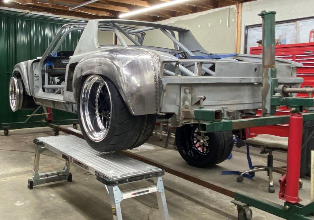
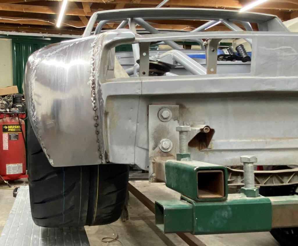
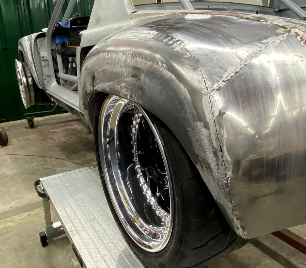
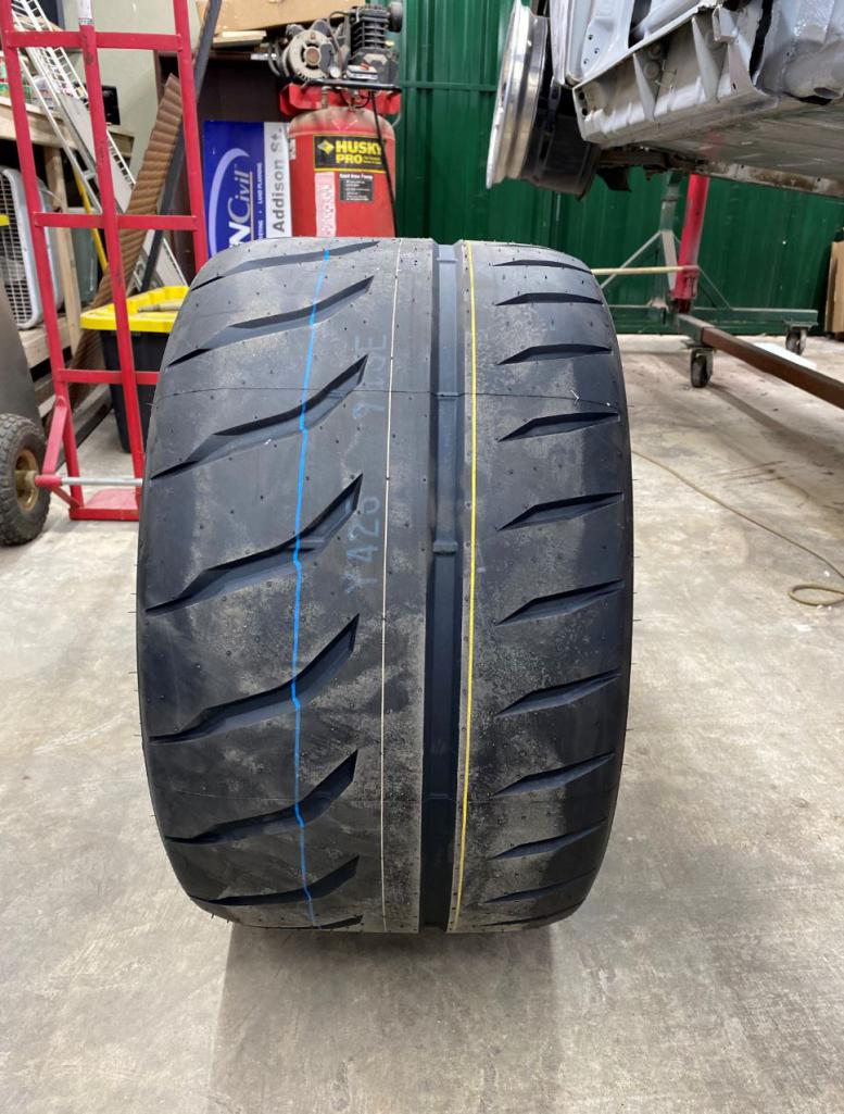
Posted by: dan10101 Feb 25 2021, 10:44 PM
So Sexy!!
Posted by: mgp4591 Feb 25 2021, 11:12 PM
That's a spicy meatball!
Posted by: ValcoOscar Feb 26 2021, 06:48 AM
So Sexy!!
Baby got back, then some
O
Posted by: sixnotfour Feb 26 2021, 08:51 AM
Tirerrific !!!
Posted by: tygaboy Feb 26 2021, 09:26 AM
WIDE you pick those tires?
Your traction makes me envious... Can't wait to see the fronts go on!
Posted by: Curbandgutter Feb 26 2021, 10:58 AM
WIDE you pick those tires?
Your traction makes me envious... Can't wait to see the fronts go on!
Don't know wide I choose them! I'm working on the fronts this weekend. I have to have the tire though since I can't have any rubbing issues. They're supposed to come in today but we shall see. I'm so stoked with the way it's coming out. You know you build it in your head and you think it's going to look a certain way........and then, after all that work it looks just like you imagined it......man that is an awesome feeling. I'm sure you know all about that! Once I have the fronts done then I will tackle installing the 7 radiators, then it's building a set of headers and down pipes for the turbos. I would like to get the car at least with the radiators installed and have a true roller by this summer......we shall see. But these fenders and rims have really put a lot of air in my sails. All of the work to this point has been hard and not as satisfying as seeing it come together with those fenders.Posted by: Curbandgutter Mar 3 2021, 03:54 PM
Moved on to the front. Had to compress the front wheel and turn both directions to make sure that the wheel would not rub. Also, the shot of the rear is still with 1" of uptravel before it bottoms out. I would like the at rest position to be 1" lower. I want 2" of uptravel.
1" uptravel left 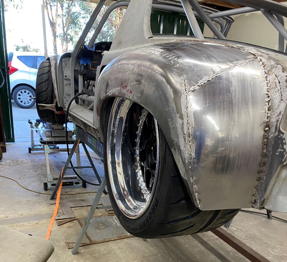
Compress and check for rubbing 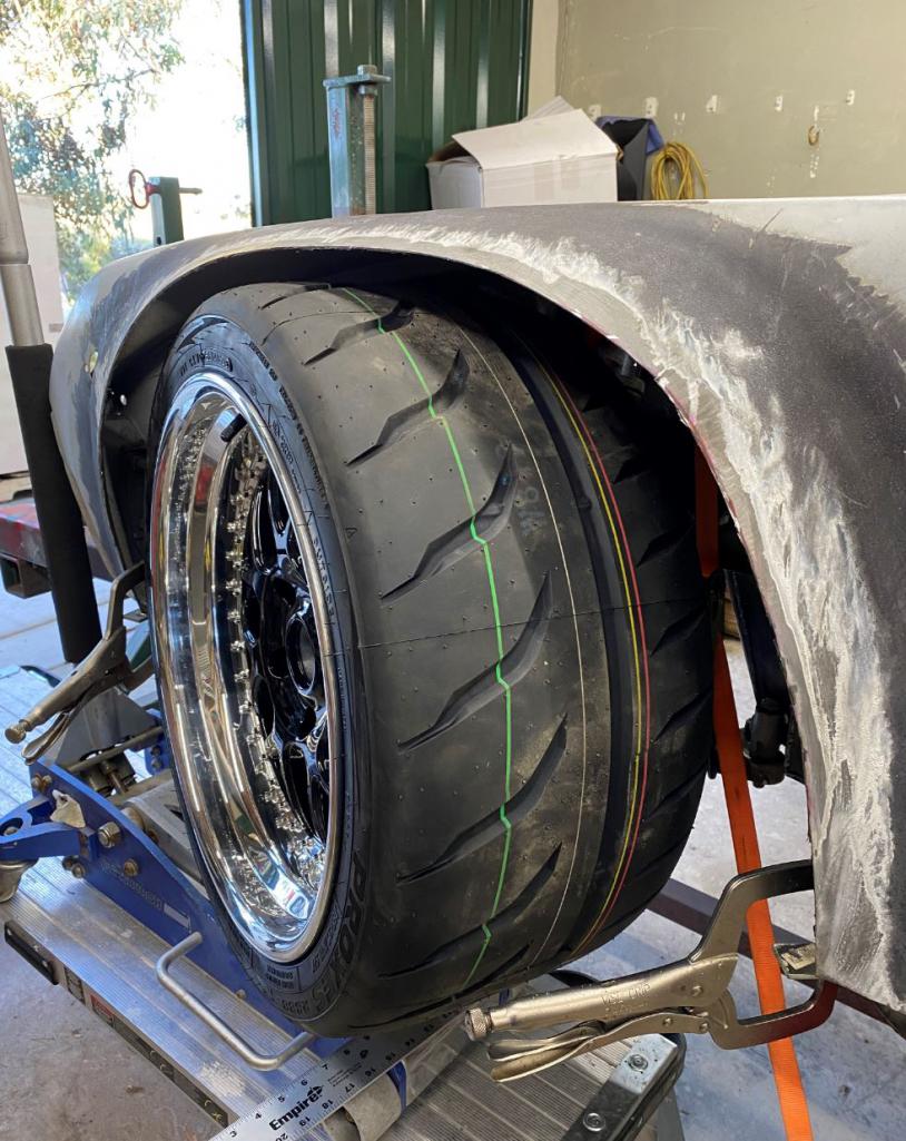
Cut out front half of fender outside face to widen the turn signal for LED projectors to fit in. Did what @JEff_Hail said to do since I couldn't get an outside skin in time, and his idea turned out to be better.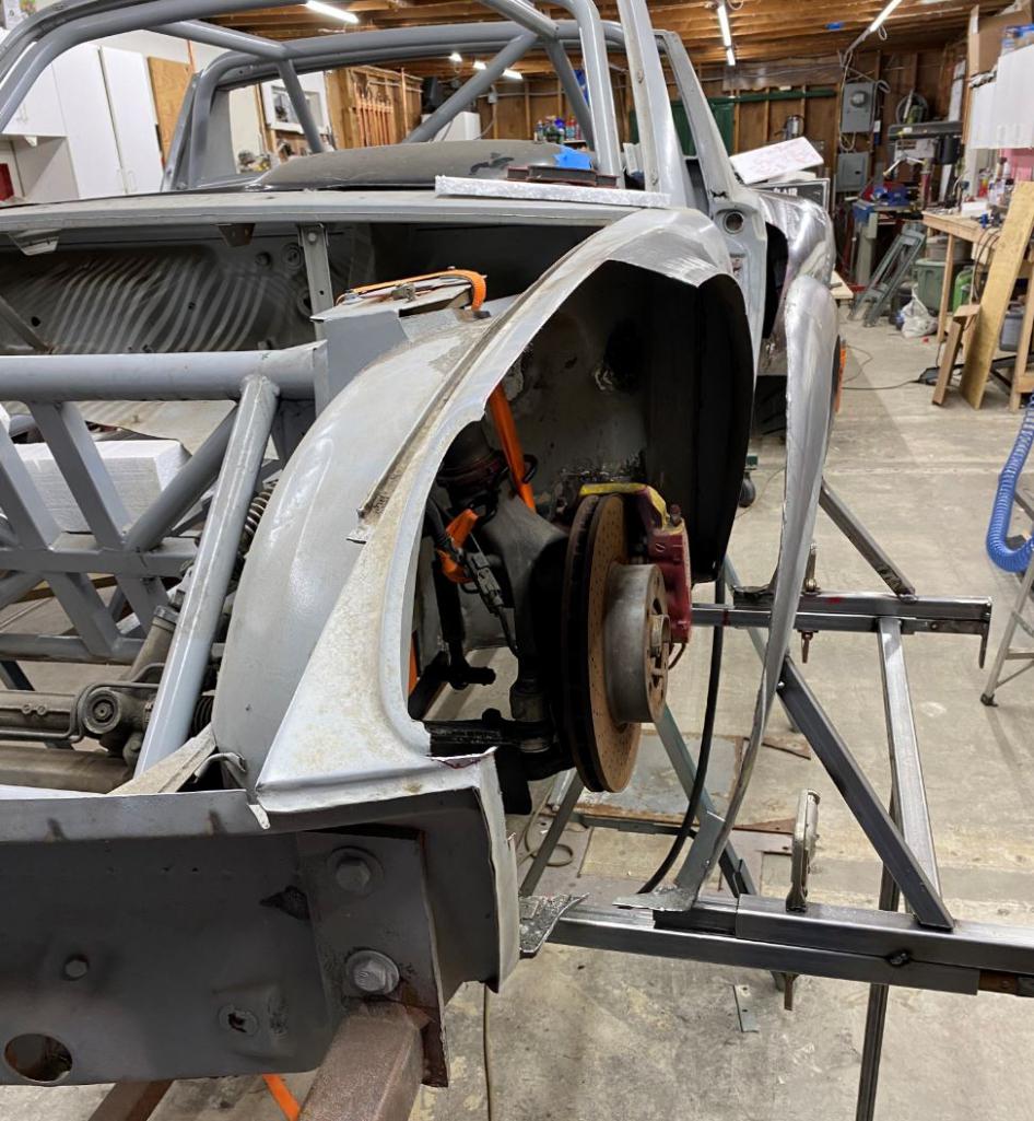
widened 1" and insert LED Projectors in here. This also makes it so that the 3" extension on the front fenders (total of 5") doesn't look weird. Yes a jig for fronts as well. 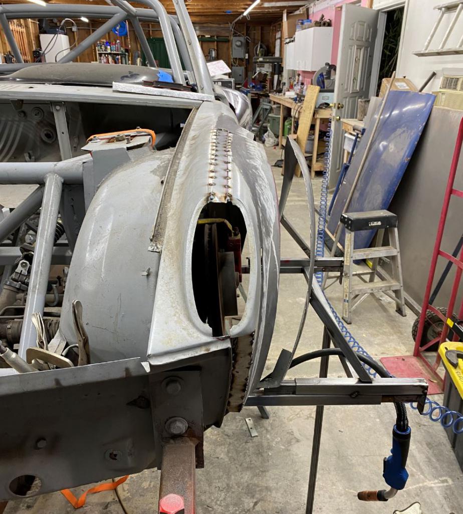
I think that I will have the drivers side front fender complete this weekend. The passenger side will be done in half the time. I spend a lot of time figuring and measuring but that's already known so it will be quick for fronts (4 hours or so).
Posted by: 76-914 Mar 3 2021, 05:30 PM
Damn, your moving right along Rudy.
Posted by: Maltese Falcon Mar 3 2021, 08:58 PM
Rudy's 914 Got the meats like Arby's & the deep dish like a Chicago pie
Posted by: pete000 Mar 3 2021, 09:08 PM
You win the widest 914 award hands down, I love it !
Posted by: Krieger Mar 3 2021, 11:29 PM
DAMN! Can you just clear coat your car and call her the Stiched Bitch!?
Posted by: Curbandgutter Mar 4 2021, 11:26 PM
You win the widest 914 award hands down, I love it !
Posted by: Curbandgutter Mar 4 2021, 11:27 PM
Rudy's 914 Got the meats like Arby's & the deep dish like a Chicago pie
Hey Marty, maybe I should call it Gino's East??
Posted by: Curbandgutter Mar 4 2021, 11:31 PM
Damn, your moving right along Rudy.
It's amazing what you can do when you're not building a shop or collecting tools for a build.
Or building a chassis table, or chassis jig, or rotiserrie, or welding table, or plumbing a couple hundred feet of copper for air, or........you get the drift. I can actually spend my time building the car. I'm loving it!!Posted by: Maltese Falcon Mar 5 2021, 12:51 AM
Rudy's 914 Got the meats like Arby's & the deep dish like a Chicago pie
Hey Marty, maybe I should call it Gino's East??
Deep Dish be like ...now in Studio City on Riverside

Posted by: Jeff Hail Mar 5 2021, 01:35 AM
Rudy's 914 Got the meats like Arby's & the deep dish like a Chicago pie
Hey Marty, maybe I should call it Gino's East??
Deep Dish be like ...now in Studio City on Riverside
Glad slitting the fender on the crown worked out. I would have gone all the way back to the windshield post and just went RSR vented style at the rear. In any case keeping the original silhouette will look right and follow the original shape. Glad you went with it. Get a 3 inch long piece of pipe about 1-1/2 inches in diameter, debur and round the edges, use it for a dolly on the underside of the fender crown. It will look nice when you are done.
Marty stop that deep dish stuff. I was by the parlor on Monday and knew I should have stopped in for a take home pie. I have heard good things about Ginos. That picture did me in.
Posted by: Curbandgutter Mar 5 2021, 11:54 AM
@maltese_falcon are you serious.......I had the best deep dish pizza ever at Gino's East in Chicago.....never had another like it, especially their sausage it's like no other. I'll be in Calabassas visiting family this weekend and will definitely stop by on the way. Thanks for the heads up.......even though it's not 914 related
@Jeff_Hail I have a crown in the fender but it's along where it ties into the face of the 916 flare. I wheeled it along the edge then put it in a die to really turn the edge See photos. Are you saying to lift the middle of the flare? By the way, it's funny that you mention the louvers since I've been mulling that around for the front fenders. That will release air from the radiators. 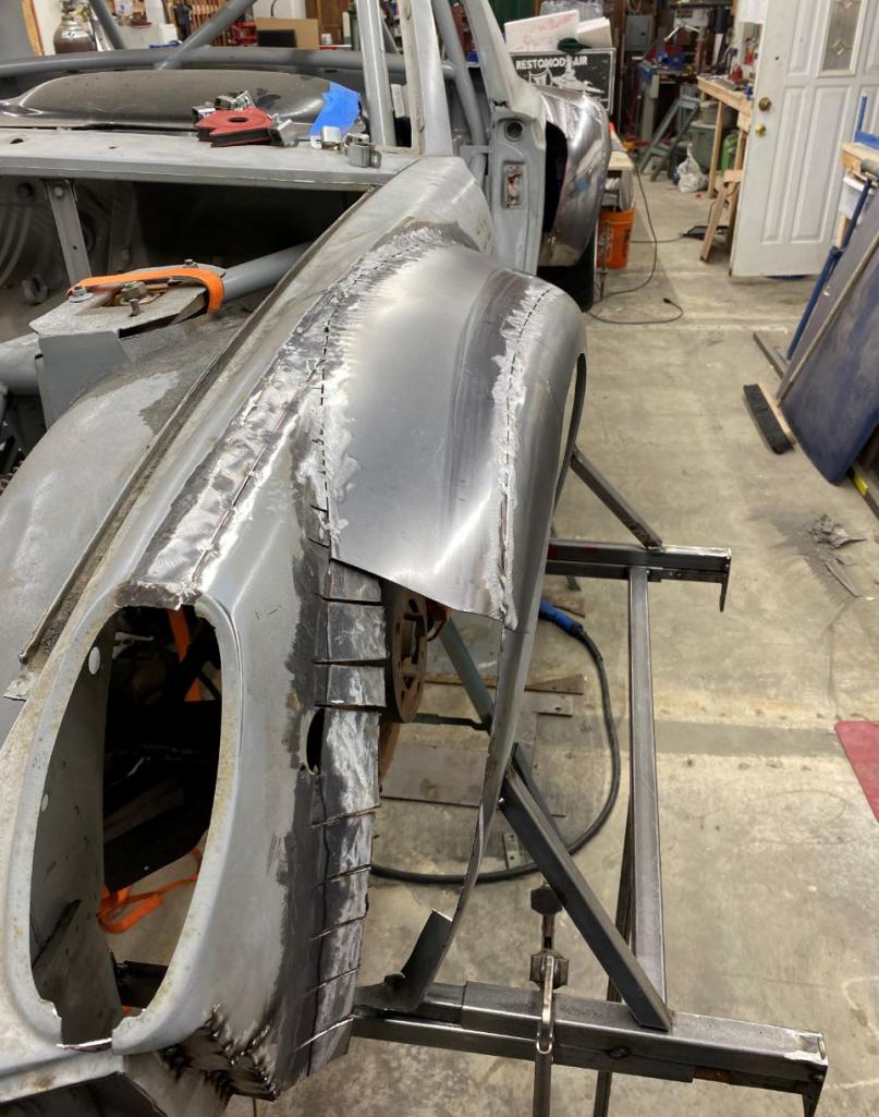
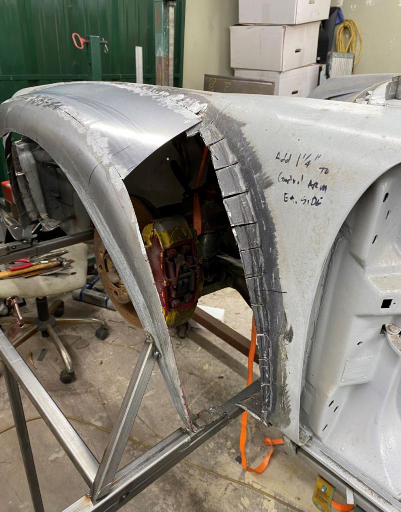
Posted by: Jeff Hail Mar 5 2021, 02:44 PM
@maltese_falcon are you serious.......I had the best deep dish pizza ever at Gino's East in Chicago.....never had another like it, especially their sausage it's like no other. I'll be in Calabassas visiting family this weekend and will definitely stop by on the way. Thanks for the heads up.......even though it's not 914 related
@Jeff_Hail I have a crown in the fender but it's along where it ties into the face of the 916 flare. I wheeled it along the edge then put it in a die to really turn the edge See photos. Are you saying to lift the middle of the flare? By the way, it's funny that you mention the louvers since I've been mulling that around for the front fenders. That will release air from the radiators.
The second photo lets me see whats going on behind the wheel opening. I like what you are doing. The crown would be the top of the fender from the lamp opening to the cowl where you slit the fender and added material.
I was thinking hang the flare first then slit the top crown of the fender to widen the entire fender even more. It would bring the entire fender outward from the lamp to the door. Referring to rsr style would run along these lines and vent the rear of the fender at the door.
Attached image(s)
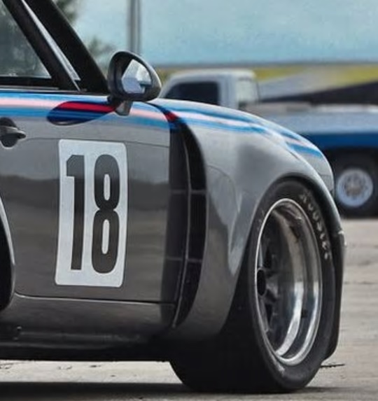
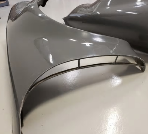
Posted by: racerbvd Mar 5 2021, 04:11 PM
Rudy's 914 Got the meats like Arby's & the deep dish like a Chicago pie
Hey Marty, maybe I should call it Gino's East??
Deep Dish be like ...now in Studio City on Riverside
Ah man, now I want a pizza .
Posted by: ValcoOscar Mar 6 2021, 12:46 AM
This build reminds me of this other mega-wide 914
O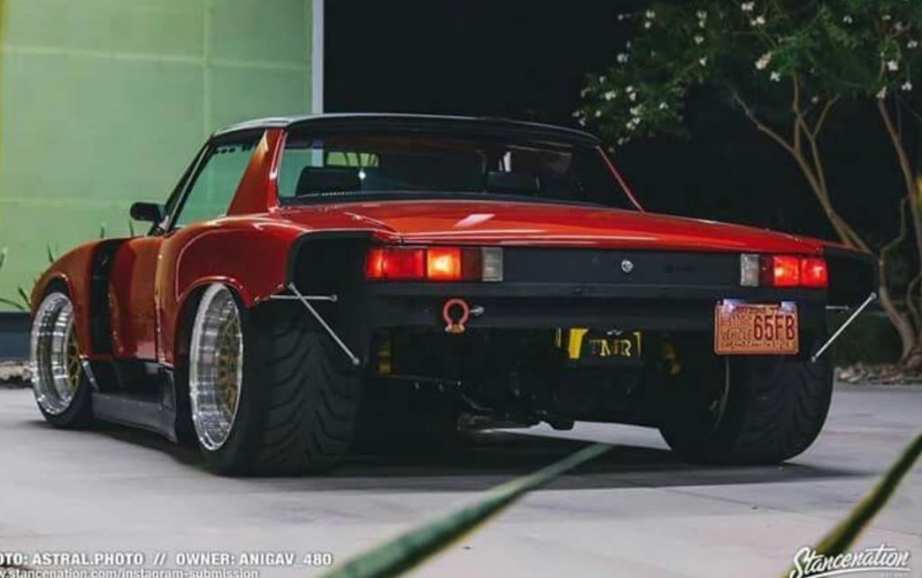
Posted by: Maltese Falcon Mar 6 2021, 10:46 AM
This build reminds me of this other mega-wide 914
O
The owner has it up for sale on InstaG
Chevy SB power
Posted by: sixnotfour Mar 6 2021, 10:52 AM
REDRUM
Attached image(s)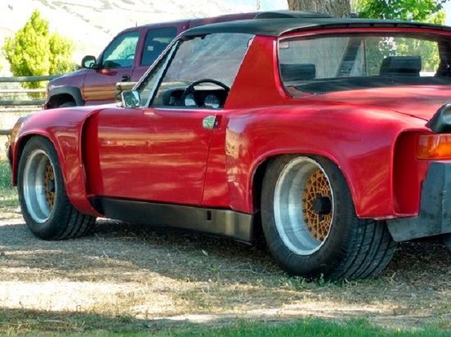
Posted by: Rand Mar 7 2021, 02:34 AM
REDRUM
butta six
It's not butta face
Oh, itza
?)

Posted by: Curbandgutter Mar 8 2021, 01:39 PM
@http://www.914world.com/bbs2/index.php?showuser=2744 OK I see what you did there. It's what Jeff Hail was talking about...the RSR look. Looks good but it's not the directions I'm going in.
Posted by: Curbandgutter Mar 8 2021, 01:46 PM
So this is what the fronts are looking like. I decided to print up a louver system for the rear of the front fender and cover it in carbon fiber. It will be very recessed into the fender and will accentuate a curve coming out of the fender to mirror the 1/4 panel.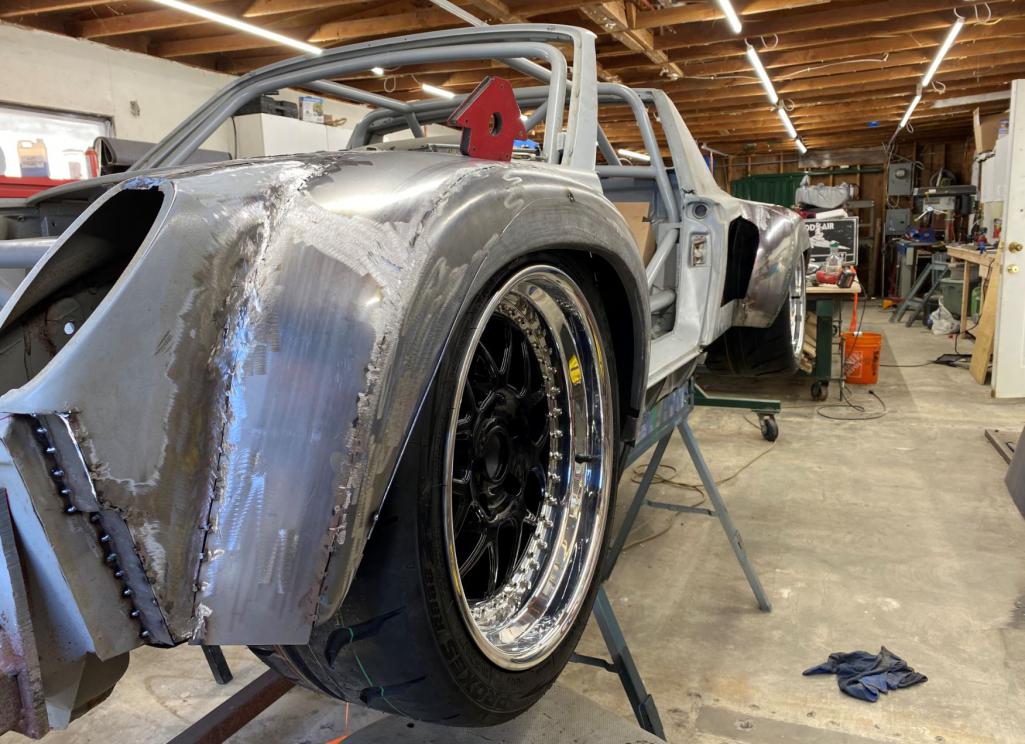
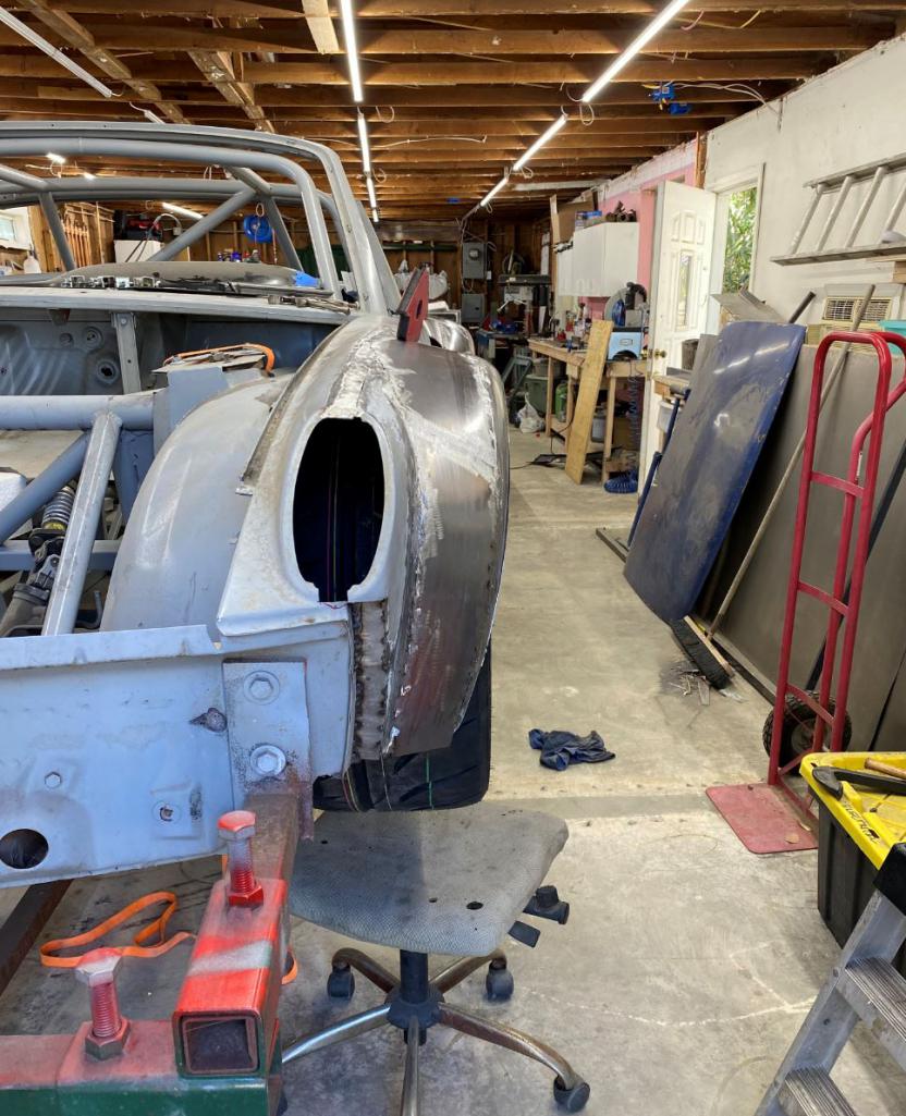
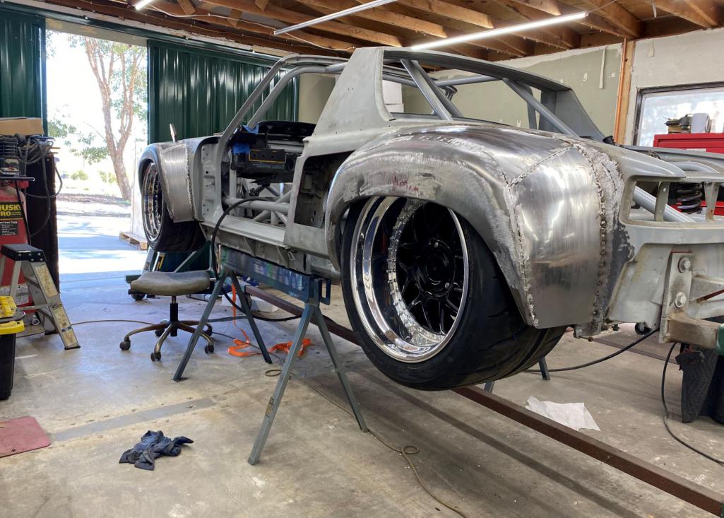
Posted by: sixnotfour Mar 8 2021, 08:40 PM
I await your vision ,, I just saw an opportunity to show REDRUM , built in SoCal early 80's...sitting in Utah..
Posted by: 914forme Mar 10 2021, 07:29 AM
Okay ah, I get the design placement but this would rule me out of sitting in either side. 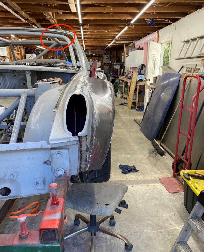
I sold a 1994 M edition Miata jut because my head would hit the top bow, I just did not fit. Knowing that in my 914 with the seat cushion in place, my head could hit the rear hoop. in my old race car. The tie in bars while going into the tie ins for the angles and rear bars, that would be very close to my head.
I'm a bit bummed by this for two reasons, one I want you to keep your head on your shoulders with out adding a plate to cover the crushed area, and if you do fit with plenty of clearance, I will never be able to ride in this sweet build because I would have to remove my head and place it in my lap. Thus removing my enthusiasm for the ride, and creating quite a biological cleanup for you.
Please just check your fit before you become a crash test dummy.
Posted by: rudedude Mar 10 2021, 08:37 AM
Is there enough room in the front fender to turn the wheel?
Posted by: Andyrew Mar 10 2021, 09:34 AM
Is there enough room in the front fender to turn the wheel?
Looks like about an inch from the wheel to the fender, Should be enough. He's got enough lip there to trim to make it fit perfectly if he needs to. Typically the 914's with wide fronts rub the inner fender.
Posted by: Andyrew Mar 10 2021, 09:35 AM
Okay ah, I get the design placement but this would rule me out of sitting in either side.
Its only there for chassis mock up to keep the car from twisting while he's doing all this work. He's mentioned a couple times he's going to remove the A to B bars.
Posted by: Curbandgutter Mar 10 2021, 11:38 AM
@http://www.914world.com/bbs2/index.php?showuser=2388 "I will never be able to ride in this sweet build because I would have to remove my head and place it in my lap. Thus removing my enthusiasm for the ride, and creating quite a biological cleanup for you".......... you're crazy man! Yes, those bars will be gone. If you look closely they are only tacked on.
@http://www.914world.com/bbs2/index.php?showuser=3387 if you look closely the lip is tacked on and I will adjust as needed when I put back on the ground and compress with about 600# of weights. Don't worry at the end of the day it will not rub cause I can and
Posted by: Jeff Hail Mar 10 2021, 07:40 PM
Looks good.
Posted by: 2mAn Mar 12 2021, 06:52 PM
So badass...
Posted by: Curbandgutter Mar 15 2021, 01:12 PM
Thanks guys.
I semi completed all the fenders. I need to finish the rocker panels before I finish welding the fenders. I tried different bends to get to the final depth that I wanted. The final rocker will have a rubber strip and fastened like Marv's 6 project. Here are some update pictures.
This is how the the front wide-body is looking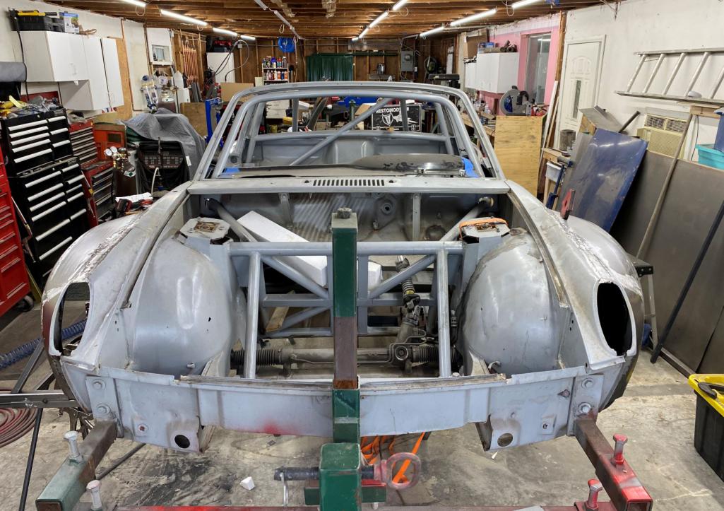
bend cut try again 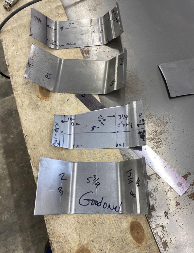
getting closer 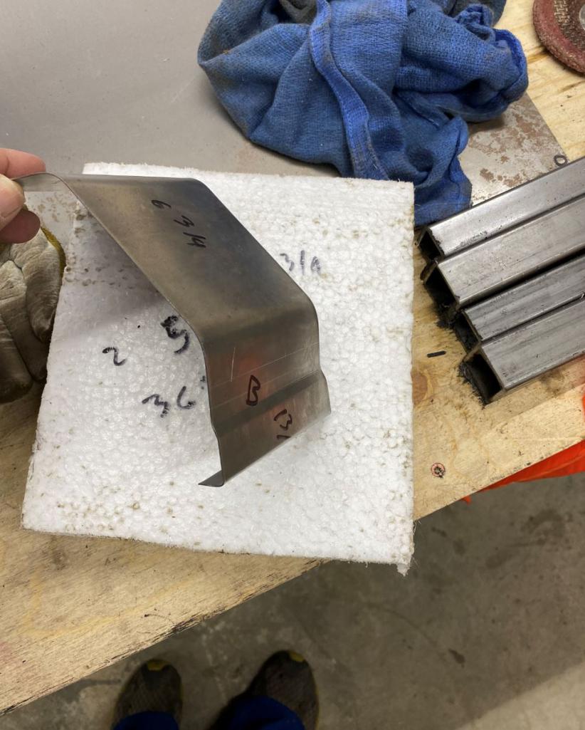
this one ( 1.5" radius and offset along lower lip or 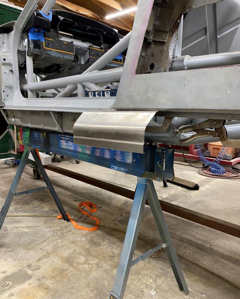
this one ( 2" radius and no offset along lower lip) I think the previous one was starting to
look like crown molding 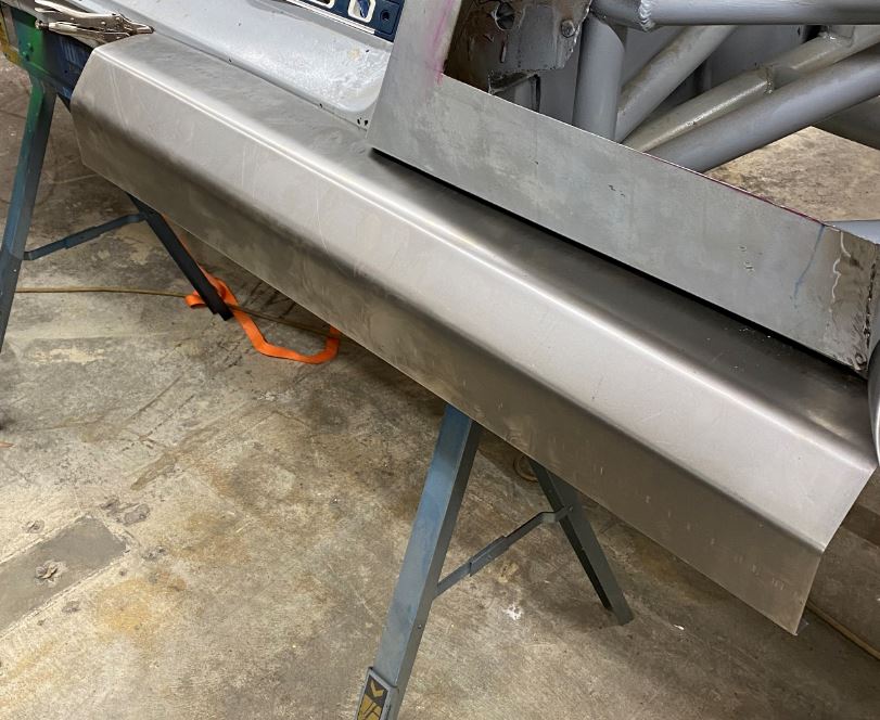
Posted by: watsonrx13 Mar 19 2021, 06:53 AM
Well done Rudy. What gauge are you using for the rocker panels? Also, can you describe/show what you're using to shape/bend the metal?
Posted by: siverson Mar 19 2021, 09:22 AM
Awesome - keep the updates coming!
-Steve
Posted by: Curbandgutter Mar 20 2021, 06:23 PM
Well done Rudy. What gauge are you using for the rocker panels? Also, can you describe/show what you're using to shape/bend the metal?
Im using 22 gauge on the rocker panels. I use a sheet metal magnetic brake to bend everything. I used a 2" pipe as a backer to get the brake to brake a radius as opposed to a sharp corner.
Posted by: Curbandgutter Mar 20 2021, 06:24 PM
Awesome - keep the updates coming!
-Steve
Thanks Steve, I'm really pushing hard right now.
Posted by: Curbandgutter Mar 20 2021, 06:32 PM
More update on the rocker panels. I just need to finish the ends.....that's easy. The hard part was getting these things to mount sturdily on the car and make them removable and allow conduits to pass through. I designed to give me flexibility to run whatever conduits I want in the rockers or the longs. 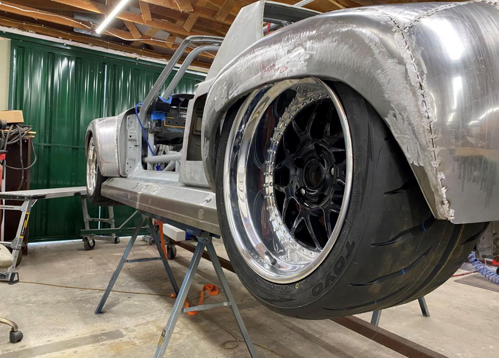
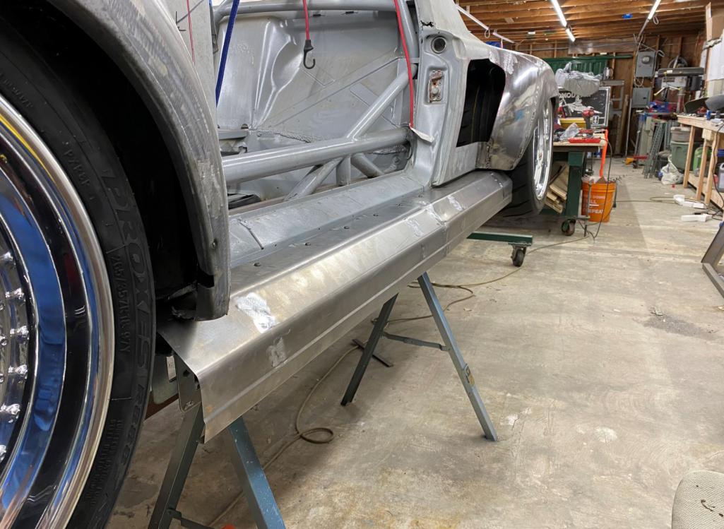
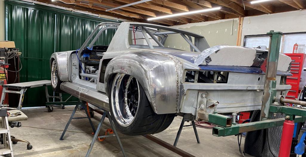
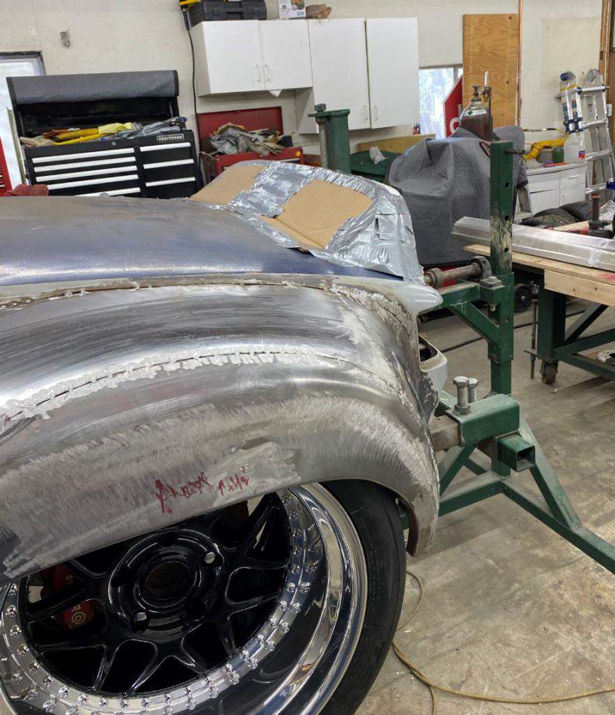
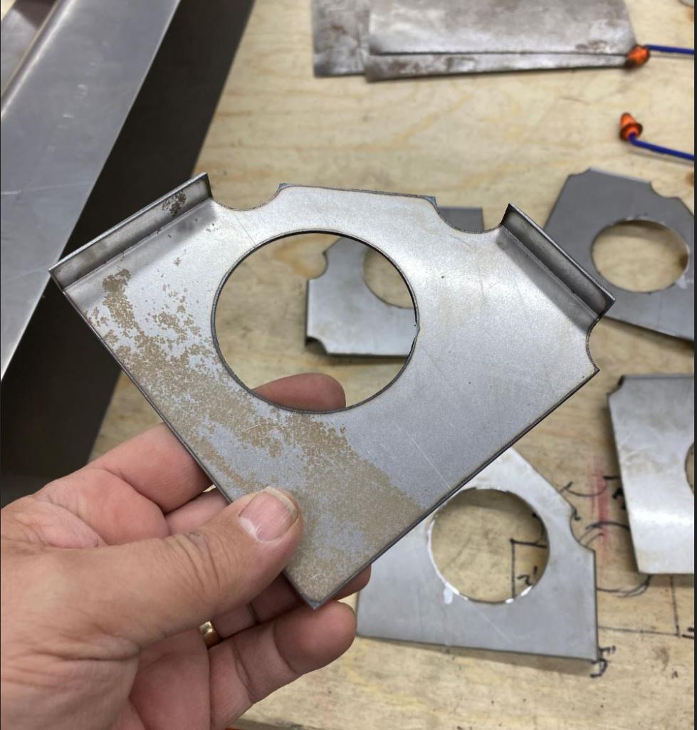
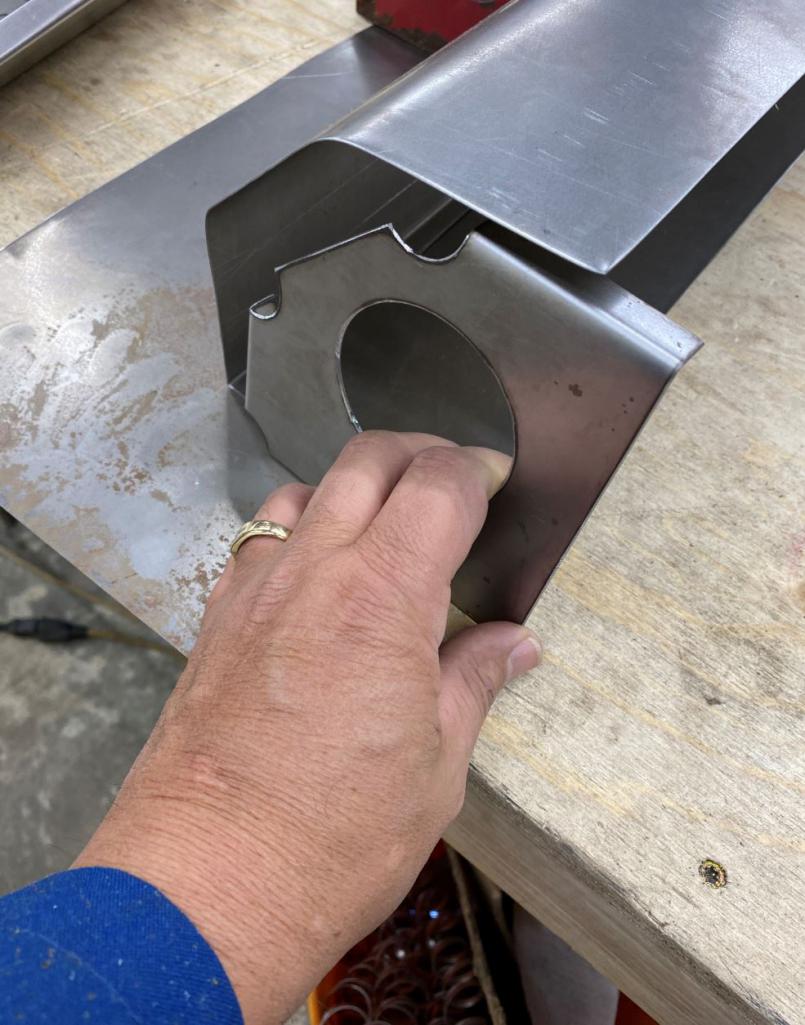
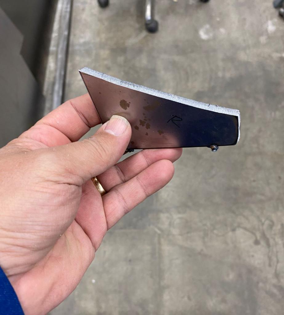
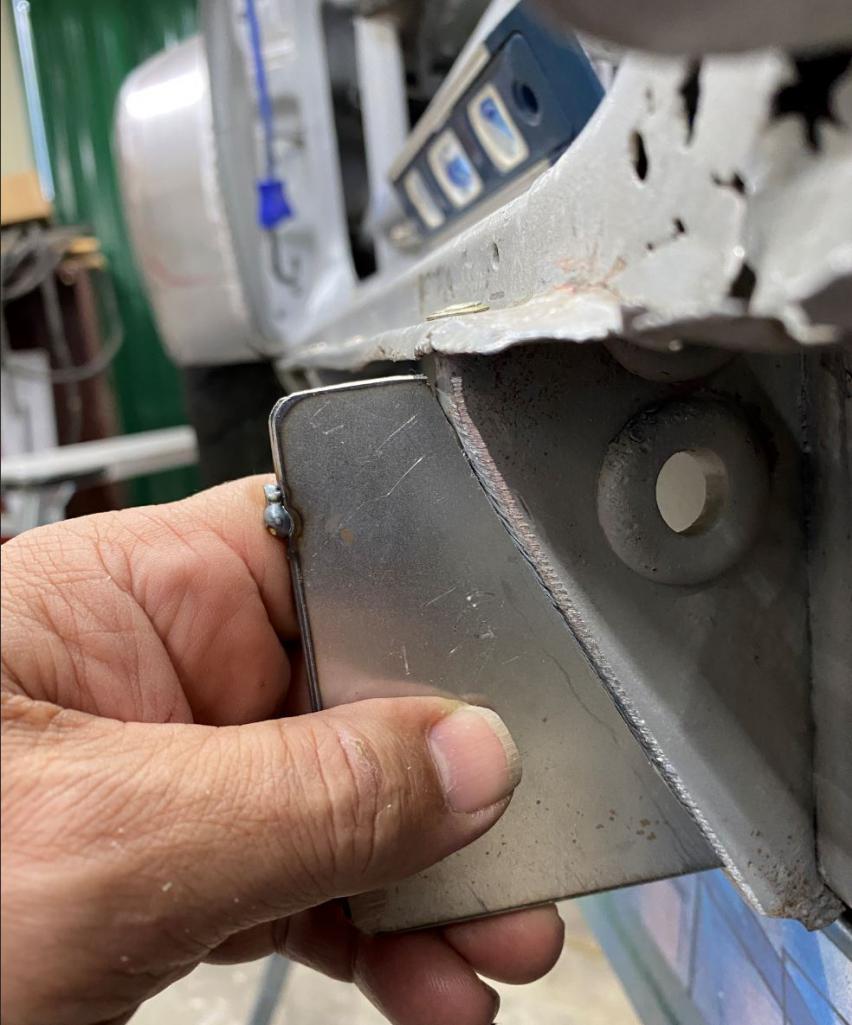
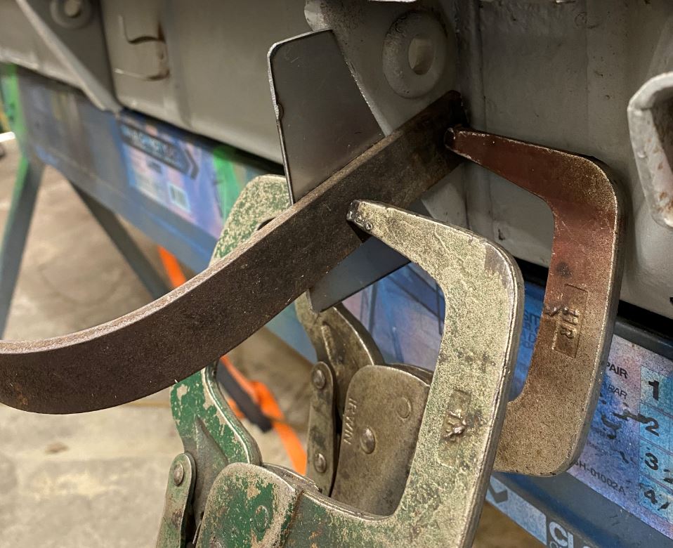
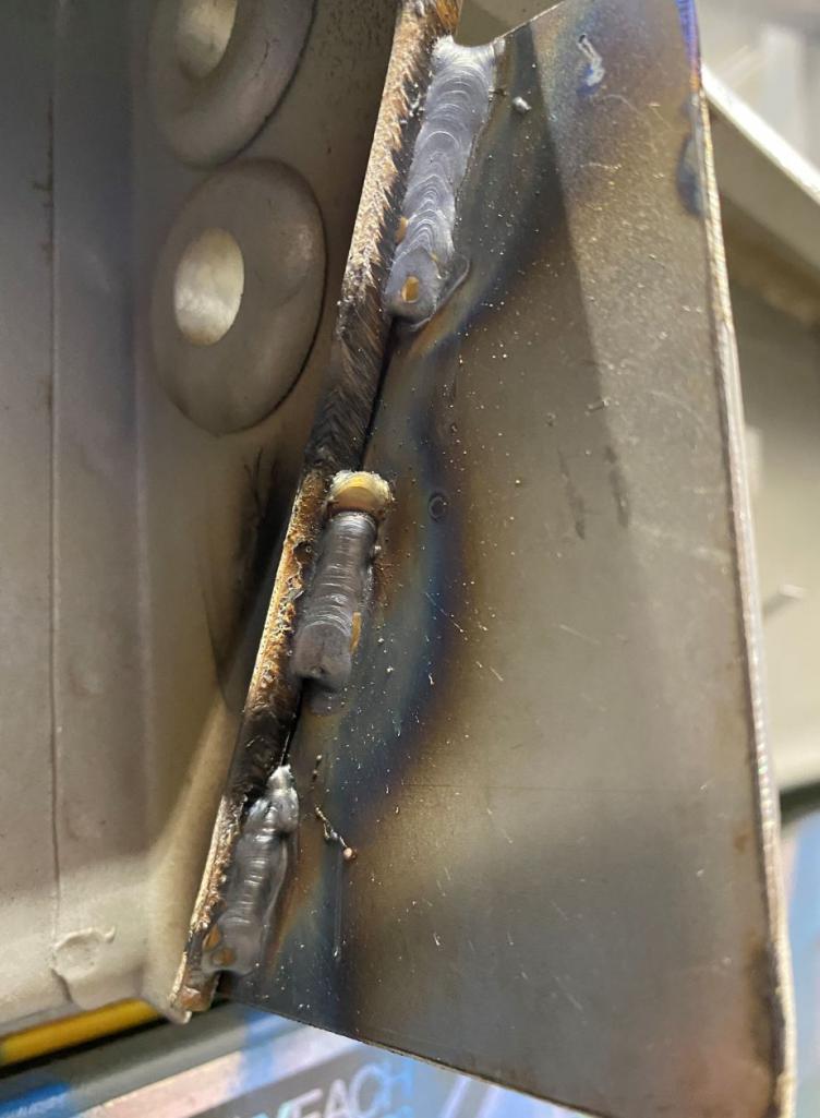
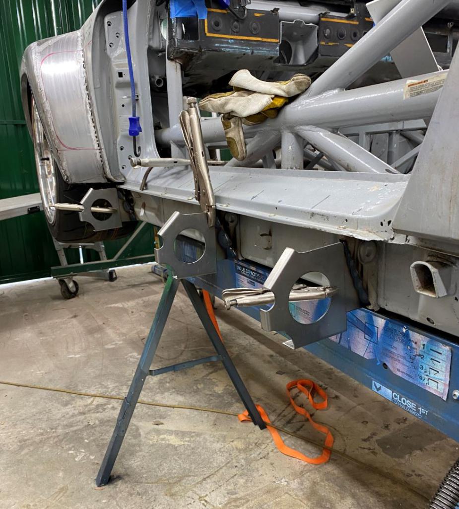
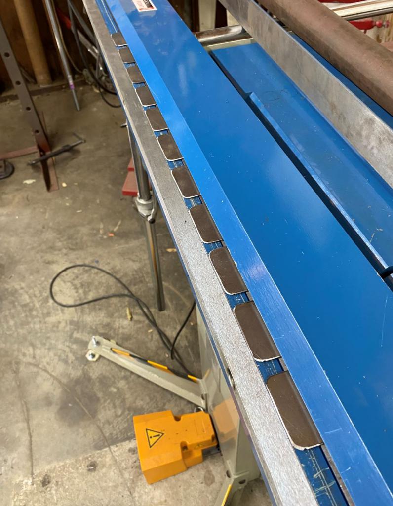
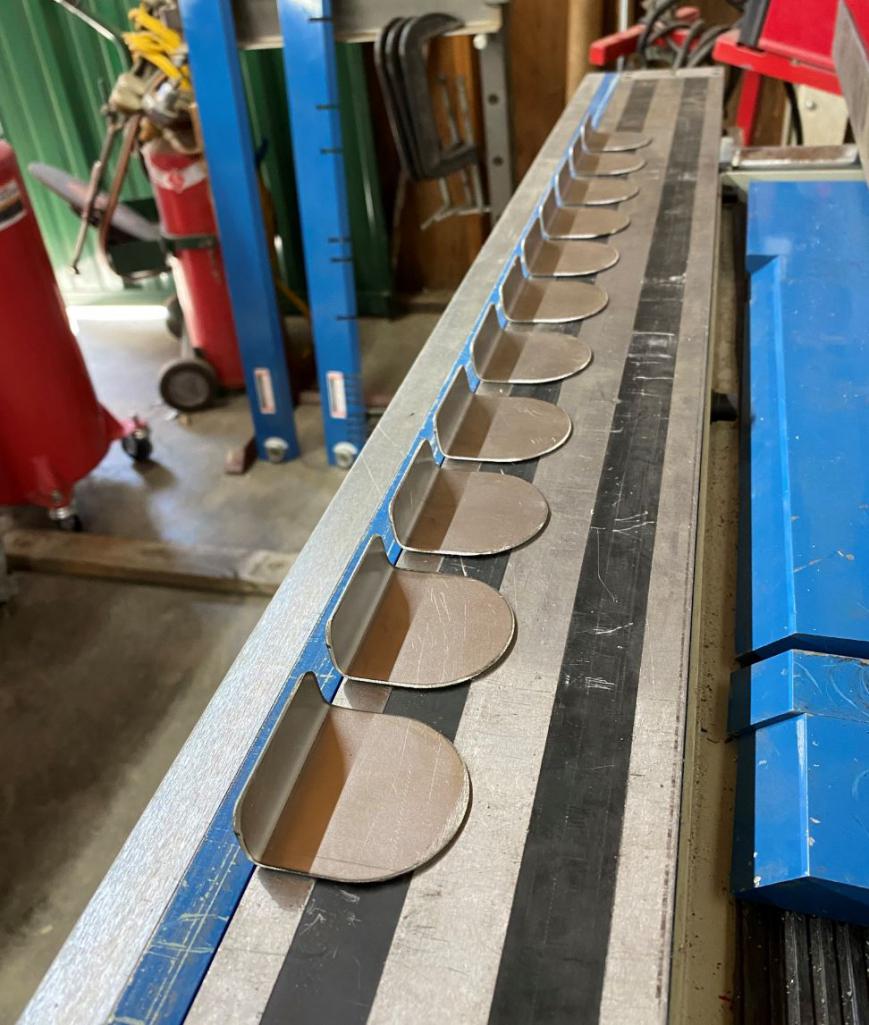
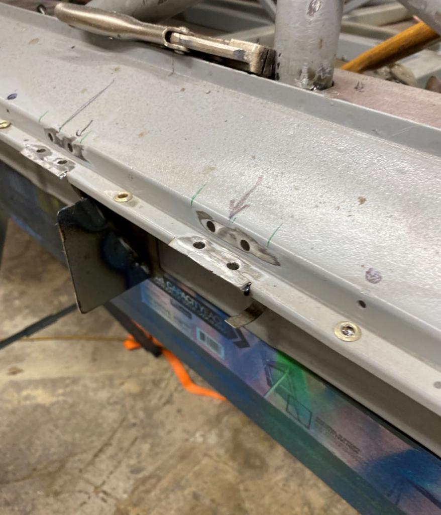
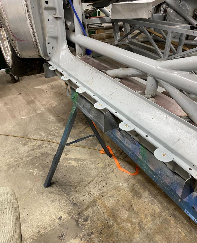
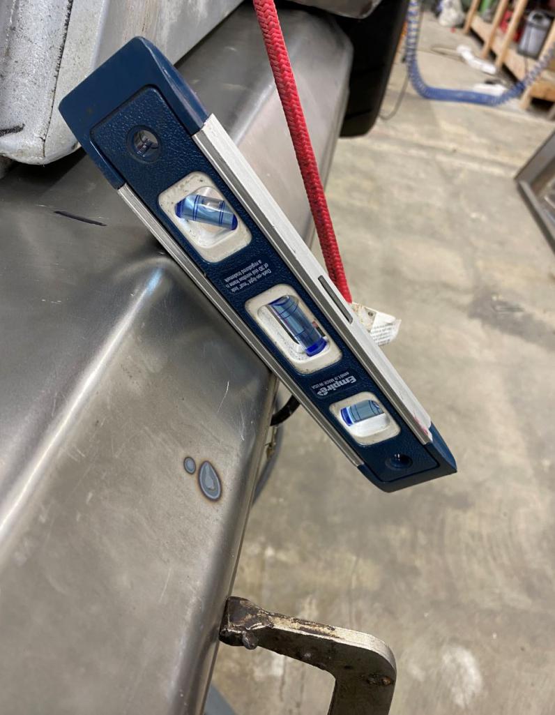
Posted by: 76-914 Mar 20 2021, 06:53 PM
You're having entirely too much fun Rudy. You may not want to go back to work after this. I was going to come by but I spent the last "2" days re-entering every invoice, deposit and pay check for the last 6 weeks. Friggin computers. We're leaving for TX to see the grandkids I won't get by for a couple of more weeks now. Hopefully I'll be back in time for the first drive! BTW, it's looking really good Rudy.
Posted by: EdwardBlume Mar 21 2021, 06:39 AM
Art and talent. Well done! You inspire all of us. Thanks for sharing!
Posted by: Curbandgutter Mar 23 2021, 03:08 PM
Art and talent. Well done! You inspire all of us. Thanks for sharing!
Thanks bud. I am thinking on cutting down on the amount of pictures I post since it takes a long time to prep and it just seems that people care more of the finished money shot rather than the back of the house stuff. So next post will more than likely be the finished rockers, then the finished duck tail and then the finished hood. It will be easier for me that way. Later!
Posted by: jd74914 Mar 23 2021, 03:30 PM
I love the progress shots Rudy!
For me the slowest part is always resizing images. If that's your issue, I highly recommend installing ImageRisizer (now part of MS PowerToys). Then it's just a right click to resize and you're good to load.
https://www.bricelam.net/ImageResizer/
Posted by: watsonrx13 Mar 23 2021, 04:20 PM
Art and talent. Well done! You inspire all of us. Thanks for sharing!
Thanks bud. I am thinking on cutting down on the amount of pictures I post since it takes a long time to prep and it just seems that people care more of the finished money shot rather than the back of the house stuff. So next post will more than likely be the finished rockers, then the finished duck tail and then the finished hood. It will be easier for me that way. Later!
I know it's time consuming to post these pic and the associated wording, but there are a lot of us that really enjoy the steps taken to get to the results. BTW, thanks for responding to my post regarding your sheet metal brake.
Posted by: Curbandgutter Apr 11 2021, 08:01 PM
Side skirt metal work is done. Took 15 Riv nuts to install each side. Next is finish welding the fenders then on to the rear hood and metal duck spoiler. 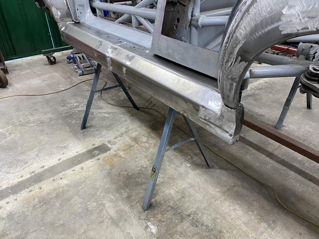
Posted by: Curbandgutter Apr 11 2021, 08:04 PM
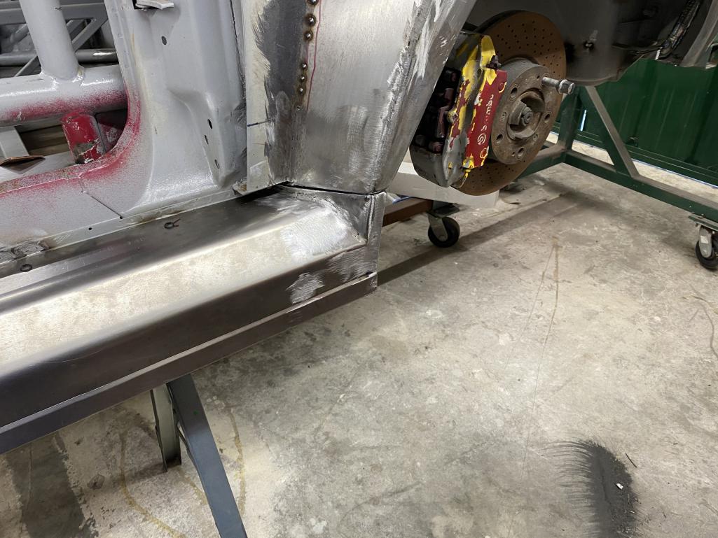
Posted by: Curbandgutter Apr 11 2021, 08:05 PM
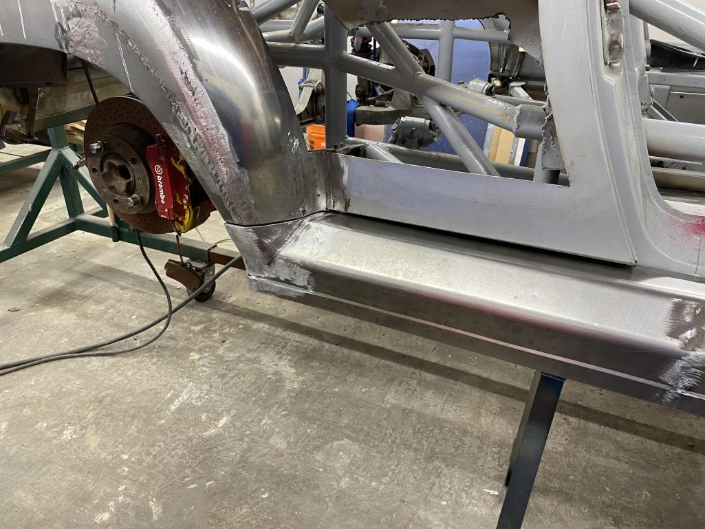
Posted by: Curbandgutter Apr 11 2021, 08:07 PM
Strength test 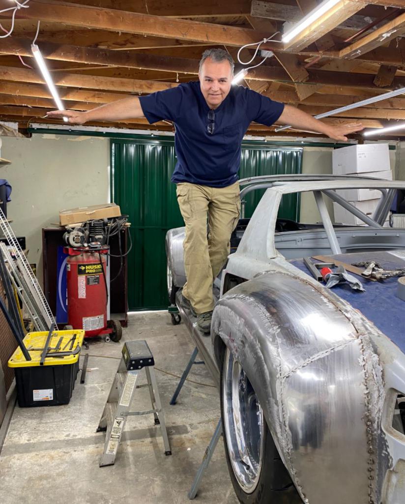
Posted by: Shivers Apr 11 2021, 08:58 PM
Very cool
Posted by: barefoot Apr 12 2021, 03:21 PM
More update on the rocker panels. I just need to finish the ends.....that's easy. The hard part was getting these things to mount sturdily on the car and make them removable and allow conduits to pass through. I designed to give me flexibility to run whatever conduits I want in the rockers or the longs.
I don't think those tyres are wide enough
Posted by: strawman Apr 12 2021, 03:48 PM
I, too, really enjoy seeing how you're planning, fabricating and executing. Please keep up the great work, and thanks for sharing!!!
Posted by: Curbandgutter Apr 12 2021, 04:26 PM
It's good to hear from the peeps that are interested. It seems that the nature of this beast is such that it has so much non-914 content that it automatically excludes an entire segment that would otherwise engage if it were something more of things that they would want to do on their car. At this point I'm adding pictures more for record keeping. Next step is to finish welding the flares. Hopefully I will start building the all metal duck tail (different from what is out there right now), cut up the rear hood to increase heat extraction, simultaneously lighten and stiffen the rear hood and build a trick mechanism to tilt the whole thing back.
Posted by: Curbandgutter Apr 12 2021, 04:29 PM
More update on the rocker panels. I just need to finish the ends.....that's easy. The hard part was getting these things to mount sturdily on the car and make them removable and allow conduits to pass through. I designed to give me flexibility to run whatever conduits I want in the rockers or the longs.
I don't think those tyres are wide enough
You're right!
Posted by: strawman Apr 12 2021, 04:34 PM
... At this point I'm adding pictures more for record keeping.
I hear you! I've been building my Suby-powered 914 since 2008, and I have to go back and search what I posted to remember what weird parts I've robbed from other cars/motorcycles/etc. to make my car work. Don't worry about offending anyone in the 914 community with your creativity... these cars have been hot-rodded since the 1970s, and they're still a great canvas to modify, drive and enjoy.
Posted by: Curbandgutter Apr 12 2021, 07:04 PM
@http://www.914world.com/bbs2/index.php?showuser=8624 thanks man!
Posted by: pete000 Apr 12 2021, 08:53 PM
You are very savvy with the metal !
Posted by: Blue6 Apr 12 2021, 09:37 PM
I, too, really enjoy seeing how you're planning, fabricating and executing. Please keep up the great work, and thanks for sharing!!!
Posted by: Andyrew Apr 13 2021, 09:02 AM
... At this point I'm adding pictures more for record keeping.
I hear you! I've been building my Suby-powered 914 since 2008, and I have to go back and search what I posted to remember what weird parts I've robbed from other cars/motorcycles/etc. to make my car work. Don't worry about offending anyone in the 914 community with your creativity... these cars have been hot-rodded since the 1970s, and they're still a great canvas to modify, drive and enjoy.
I've started to update my first post in my thread with as much detailed info on parts as possible. Makes a huge difference. I'm constantly forgetting the little details.
Posted by: 76-914 Apr 13 2021, 11:38 AM
... At this point I'm adding pictures more for record keeping.
I hear you! I've been building my Suby-powered 914 since 2008, and I have to go back and search what I posted to remember what weird parts I've robbed from other cars/motorcycles/etc. to make my car work. Don't worry about offending anyone in the 914 community with your creativity... these cars have been hot-rodded since the 1970s, and they're still a great canvas to modify, drive and enjoy.
I've started to update my first post in my thread with as much detailed info on parts as possible. Makes a huge difference. I'm constantly forgetting the little details.
If your forgetting details at your age Andrew, I don't feel so badly.
Just like Geoff, I had to go back through my receipts and build thread several times during this 2nd conversion. In fact, I need to backtrack once again to find where I purchased the shifter knob.
Posted by: FL 000 Apr 14 2021, 01:11 PM
I am enjoying the seeing the build and your impressive skills. Can’t wait to see this beast in person someday! I am guessing documenting it helps with the motivation also so keep it up
Posted by: strawman May 3 2021, 09:43 PM
I just chatted with Rudy about his plans for this car. Incredible stuff, to say the least. I'm hoping to stop by his shop in July when I'm down in his area to help my daughter and her husband move from Oceanside back to SLO County. Keep up the great work Rudy!
Posted by: Curbandgutter May 5 2021, 11:48 AM
Thanks Geoff @http://www.914world.com/bbs2/index.php?showuser=8624 I finished welding the fenders and am now buttoning up some minor issues before I prime and add "minor" amounts of, dare I say it.............BONDO.
I am moving on to the rear hood and duck tail, then suspension and front hood. At that point I will have a roller.......again!
As a side-note-flirtation-with-another-bastard idea, I heard and rode in Kent's car @http://www.914world.com/bbs2/index.php?showuser=9964 and I got the bug to install a Twin Turbo Subaru Flat 6 G33 motor. That was summarily shot down once I discovered that no one makes an adapter anymore. The last time it was made, it was by Precision Chassis and for $2,200 + Clutch.......ouch! I understand that the process to mate the G33 to Cayman S is not easy. Someone suggested, cough cough Kent, then go with Subaru STI 6 speed. Then it will be a match made in heaven.  However, I did a lil bit of homework and realized that those transaxles will not support big power as a front drive only. The ring and pinion is something like 2" less than the Cayman S........so I'M STICKING WITH 2.7 AUDI AND CAYMAN S. KENT YOU ARE NOT ALLOWED TO BRING ANYMORE JEZZEBELS IN MY SHOP. I NEED TO FINISH THIS THING!!!!
THE CAR SHALL HENCETOFORTH BE NAMED 914RS4
Posted by: 76-914 May 5 2021, 08:34 PM
Oh sure, blame it on me. You just got caught up in my exhaust's sound.
Posted by: mgp4591 May 5 2021, 10:22 PM
Oh sure, blame it on me. You just got caught up in my exhaust's sound.
But yours is so quiet Kent! It sounds almost like...a Subaru...for some reason.
Posted by: Andyrew May 6 2021, 01:26 PM
Ahh You stole the name I've been tossing around in my head for a couple years
It suits your car better though
Glad to see your still on the Audi kick! If you were local I'd give you a ride..
Remind me at WCR!!
Posted by: Curbandgutter May 6 2021, 03:34 PM
Ahh You stole the name I've been tossing around in my head for a couple years
It suits your car better though
Glad to see your still on the Audi kick! If you were local I'd give you a ride..
Remind me at WCR!!
Heck yeah, that will be fun. I do plan on going whether or not my car is finished. The name does fit and its easy to get the RS4 badge and place it next the 914 badge!
Posted by: Curbandgutter May 6 2021, 03:39 PM
This will be the badge 
Posted by: FourBlades May 7 2021, 04:09 PM
This is one of my favorite builds. I love builds that involve a lot of fabrication and creative engine, transmission and suspension swaps.
I think I learned the most from these kind of builds. I enjoy the regular stock restoration and six conversions too.
John
Posted by: RiqueMar May 22 2021, 08:24 PM
@http://www.914world.com/bbs2/index.php?showuser=15637 - Nice meeting you at the Fallbrook / Mountain View run today. Didn’t know you are only in Marietta! I’m in Oceanside, let me know if you need any extra help!
Posted by: Curbandgutter Jul 17 2021, 12:05 PM
RADIATOR EXHAUST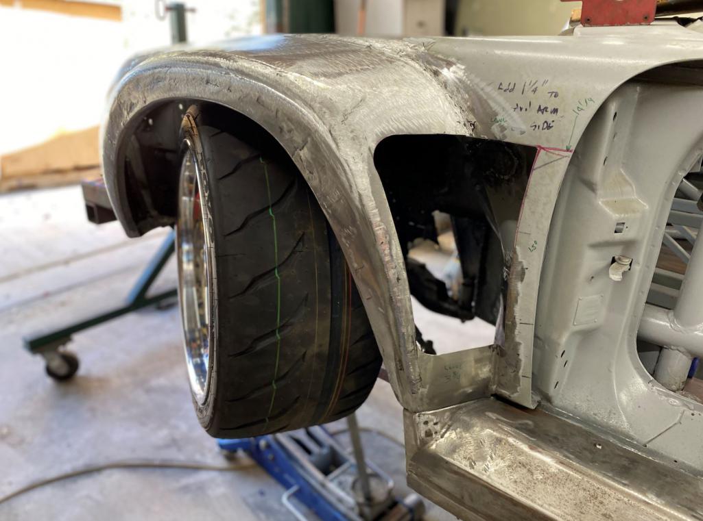
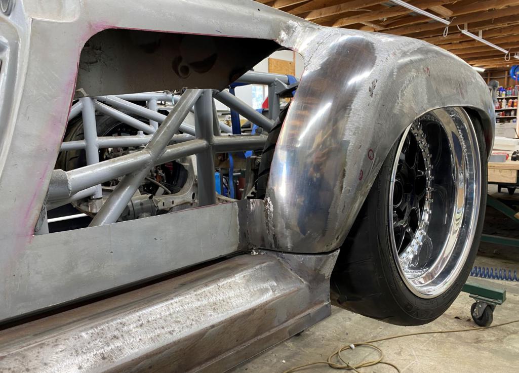
SET UP TO WELD ATTACHMENT POINTS FOR CARBON FIBER EXHAUST AND INLETS 
WELD 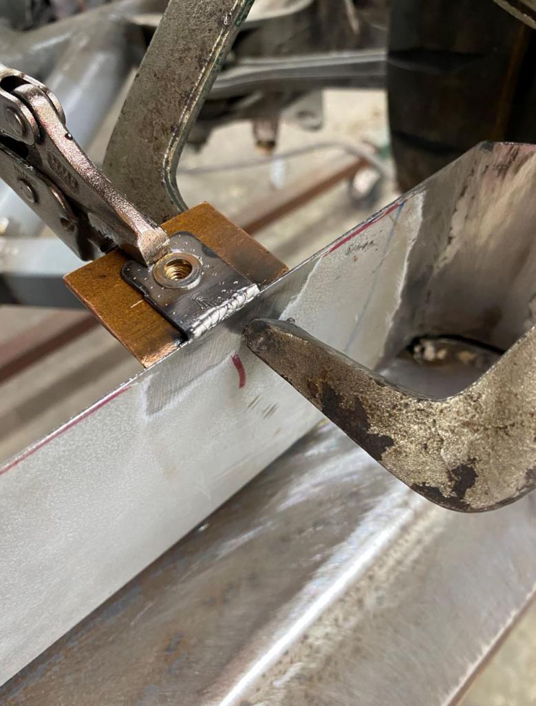
GRIND 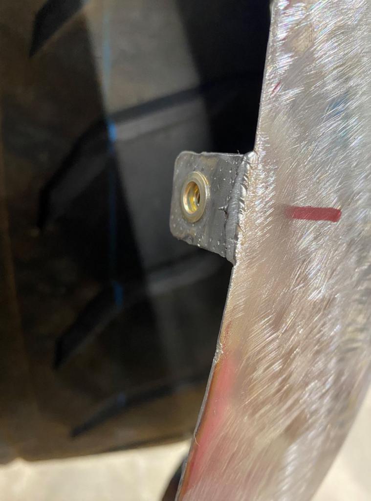
ROUGH BONDO WORK DONE ON FENDERS. WILL BE INSTALLING AN LED PROJECTOR HEADLIGHT IN THE TURN SIGNAL BUCKET 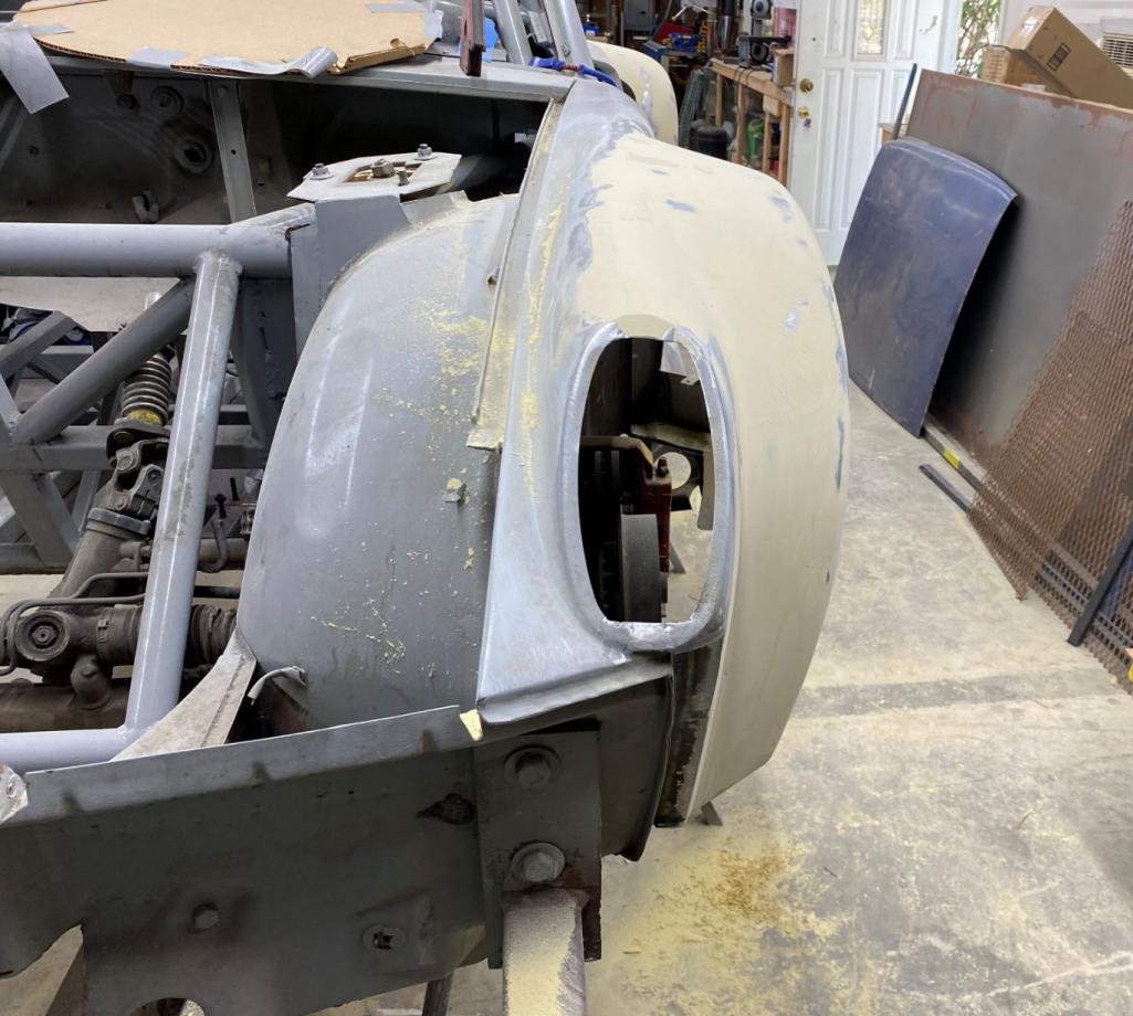
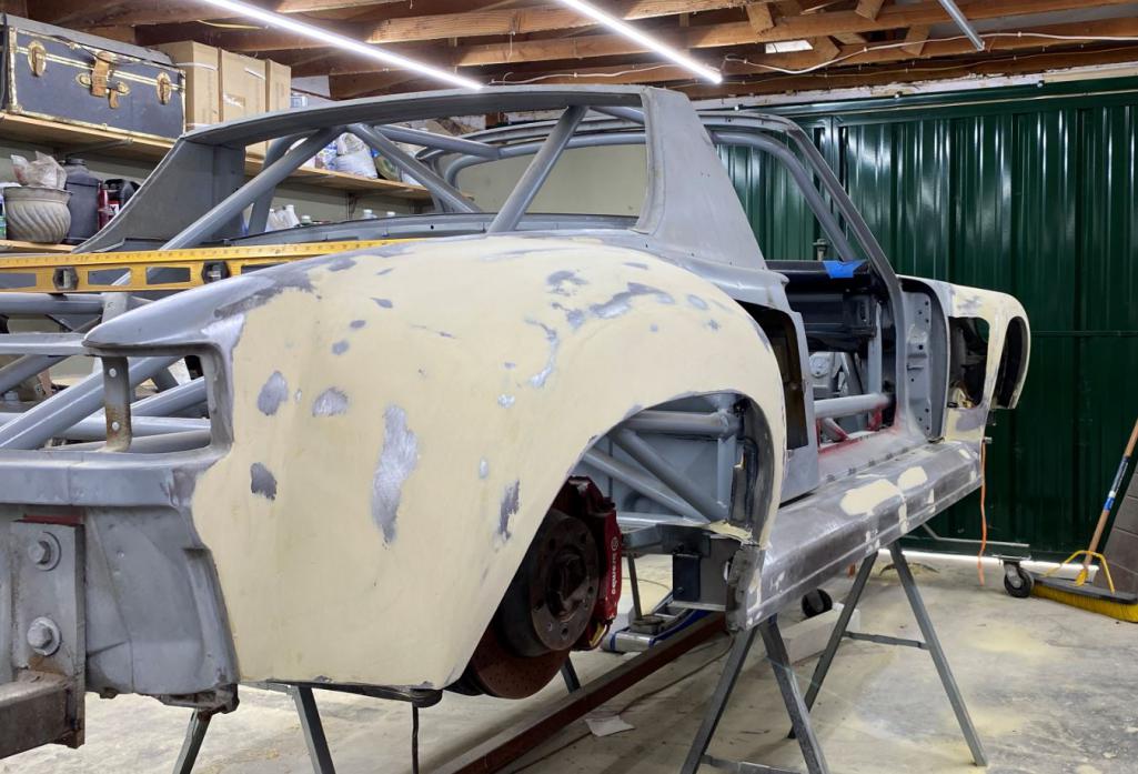
Posted by: Shivers Jul 17 2021, 04:42 PM
Very cool, can't wait for the next installment.
Posted by: DRPHIL914 Jul 19 2021, 07:04 AM
kind of has a 959ish look to it with the thresholds out over the rockers from fender to fender like that , very cool!
Posted by: 76-914 Jul 19 2021, 08:59 AM
Looking good Rudy. I haven’t seen it for awhile. Looks like I need to get my butt by there soon and check it out.
Posted by: tygaboy Jul 19 2021, 09:46 AM
Rudy -
That.
Looks.
EPIC!!!!
Wow. And having done a bit of fabrication, I can appreciate the time and effort you have in your build. And not just the actual fab work. I'd bet you have at least 2-3 times that in head-scratching and what-if'ing ahead of putting hands to metal. Not to mention the inevitable "Oh boy, I wonder if this will even work?!?"
Absolutely LOVE your ambition and execution. I can't wait to see your creation in person.
Keep up the great work!
Posted by: Curbandgutter Jul 19 2021, 12:42 PM
kind of has a 959ish look to it with the thresholds out over the rockers from fender to fender like that , very cool!
Yeah now that you mention that, I looked up a 959 image and sure enough, you’re right. Thank you
Posted by: djway Jul 19 2021, 10:58 PM
SWEEEEEEEEET
Posted by: Curbandgutter Jul 20 2021, 10:42 AM
Rudy -
That.
Looks.
EPIC!!!!
Wow. And having done a bit of fabrication, I can appreciate the time and effort you have in your build. And not just the actual fab work. I'd bet you have at least 2-3 times that in head-scratching and what-if'ing ahead of putting hands to metal. Not to mention the inevitable "Oh boy, I wonder if this will even work?!?"
Absolutely LOVE your ambition and execution. I can't wait to see your creation in person.
Keep up the great work!
@http://www.914world.com/bbs2/index.php?showuser=19241 Chris man you ain't kidding. The amount of work involved to get to this point is exhausting.......BUT WE LOVE IT DON'T WE??!! Thank you for the compliments. I'm working on the cantilevered suspension right now because I want to have a rolling chassis (AGAIN) by the end of August. After that it will be the metal duck tail and modified rear hood. Then front radiator and frunk, final twist test and then installing motor and start connecting the wiring and all plumbing.
Posted by: Curbandgutter Jul 21 2021, 12:41 PM
Looking good Rudy. I haven’t seen it for awhile. Looks like I need to get my butt by there soon and check it out.
@http://www.914world.com/bbs2/index.php?showuser=9964 Come on over. If I get my primer delivered in time I will be epoxy primering the fenders and floor. Will then hit it with high build primer and move on to the suspension. Then rear duck tail and hood.
Posted by: Curbandgutter Jul 28 2021, 06:46 PM
Headlights came in
Attached thumbnail(s)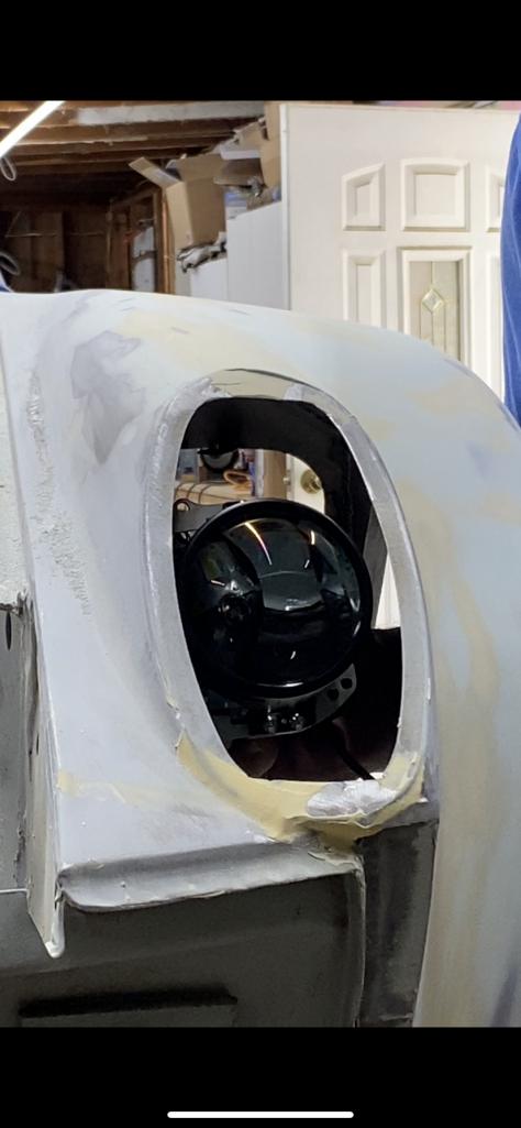
Posted by: djway Jul 28 2021, 10:09 PM
Headlights came in
This should be interesting
Posted by: mgarrison Jul 29 2021, 12:53 PM
Can you share any details on the headlights you are using...?
Posted by: Curbandgutter Jul 29 2021, 05:11 PM
Can you share any details on the headlights you are using...?
@http://www.914world.com/bbs2/index.php?showuser=23922 YES they are Morimoto LED 2.0 LED projectors with high and low beam integrated in one unit. These are supposed to be the bees knees.
now I just need to build an assembly that is adjustable, that can bolt up into the fender well, that is waterproof and I need to print up a new lense cover...thats all
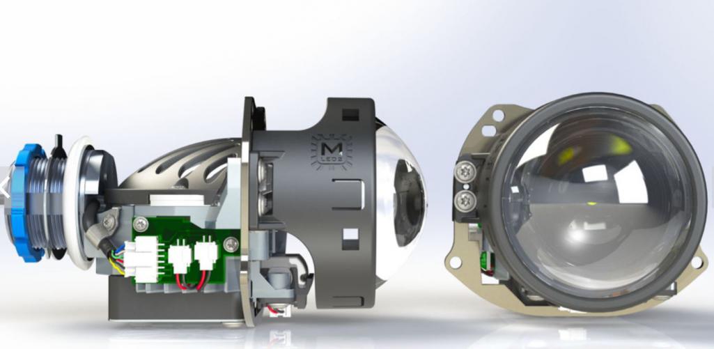
Posted by: Curbandgutter Jul 29 2021, 05:18 PM
Oh and I don't care if they are legal or not. However, they are technically being used as fog lights for which they are legal. 
I think that they would fit in a stock 914. If they do fit, I may make a run of headlight buckets and lenses if anyone is interested. They will bolt into the 914 fenders.
Posted by: mgarrison Jul 29 2021, 07:34 PM
I'd be interested! Plan on not doing popups and would love to put the lights up into the fenders.
Posted by: Andyrew Jul 30 2021, 09:47 AM
They seem long to fit in the stock headlight bucket, no?
Very cool nonetheless!
Posted by: MATTYLITE Jul 30 2021, 04:26 PM
Oh and I don't care if they are legal or not. However, they are technically being used as fog lights for which they are legal.
I think that they would fit in a stock 914. If they do fit, I may make a run of headlight buckets and lenses if anyone is interested. They will bolt into the 914 fenders.
I am 100% in for a set of clear lenses for the turn signal housings.
I too am doing headlights in those buckets on my build.
http://www.914world.com/bbs2/index.php?showtopic=206097&st=0
PM me if you're going to make them!
Posted by: 76-914 Jul 30 2021, 04:32 PM
They seem long to fit in the stock headlight bucket, no?
Very cool nonetheless!
I think Rudy is going to make his own "bucket/fixture" if I read that right.
Posted by: Andyrew Jul 31 2021, 10:15 AM
They seem long to fit in the stock headlight bucket, no?
Very cool nonetheless!
I think Rudy is going to make his own "bucket/fixture" if I read that right.
I figured. I was more commenting them fitting in a stock 914 bucket.
Posted by: Curbandgutter Aug 2 2021, 10:33 AM
Yes,
I will be making a custom headlight bucket. There's really nothing out there that can be easily modified to hold those LEDs.
Posted by: Curbandgutter Aug 2 2021, 10:50 AM
I was finally able to get a coat of epoxy primer on the fenders. The epoxy is supposed to seal the work so that water can't get to the metal and bodywork. Then I will shoot with 3 coats of high fill 2 part primer. Then block sand and get all mini waves out. I'm very happy with the body work. By the way, the primer I'm using is SPI........amazing stuff.
It's all made in the USA, and their epoxy primer happens to be sandable.
Before 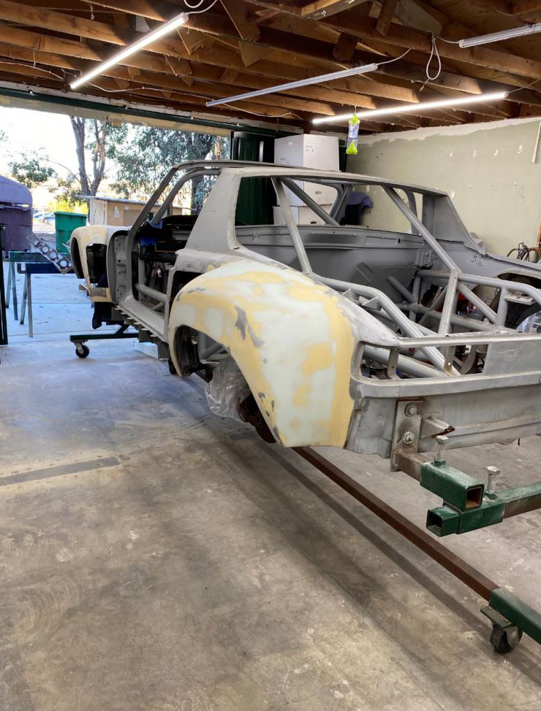
After 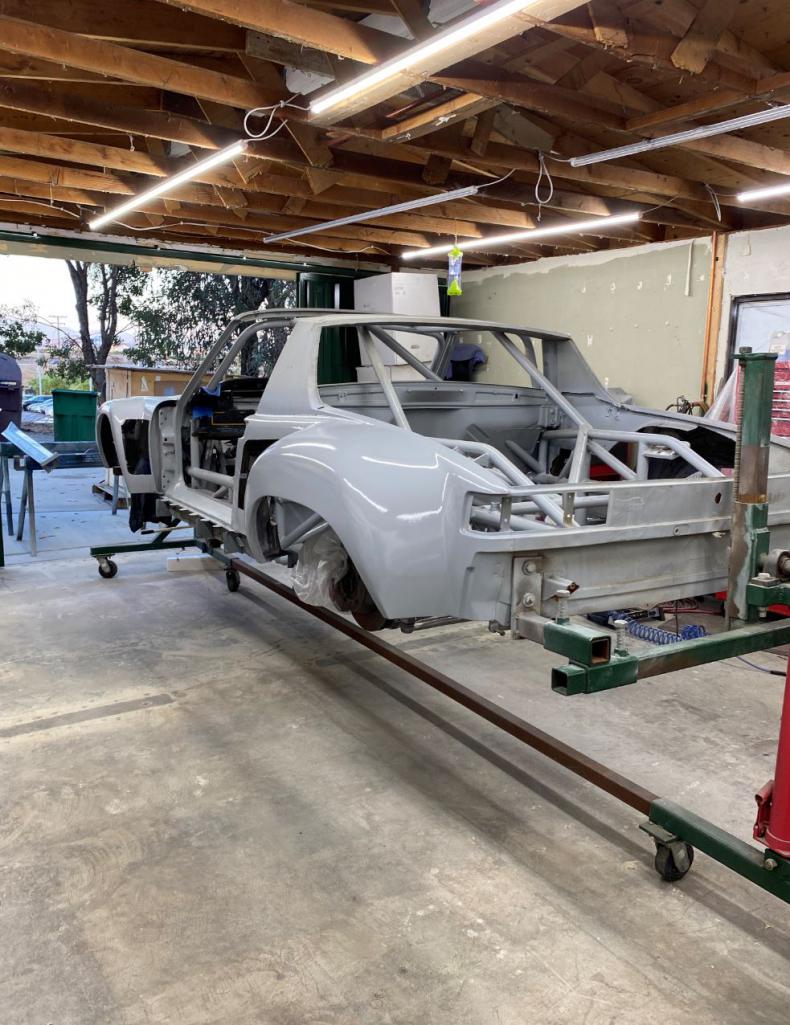
Before 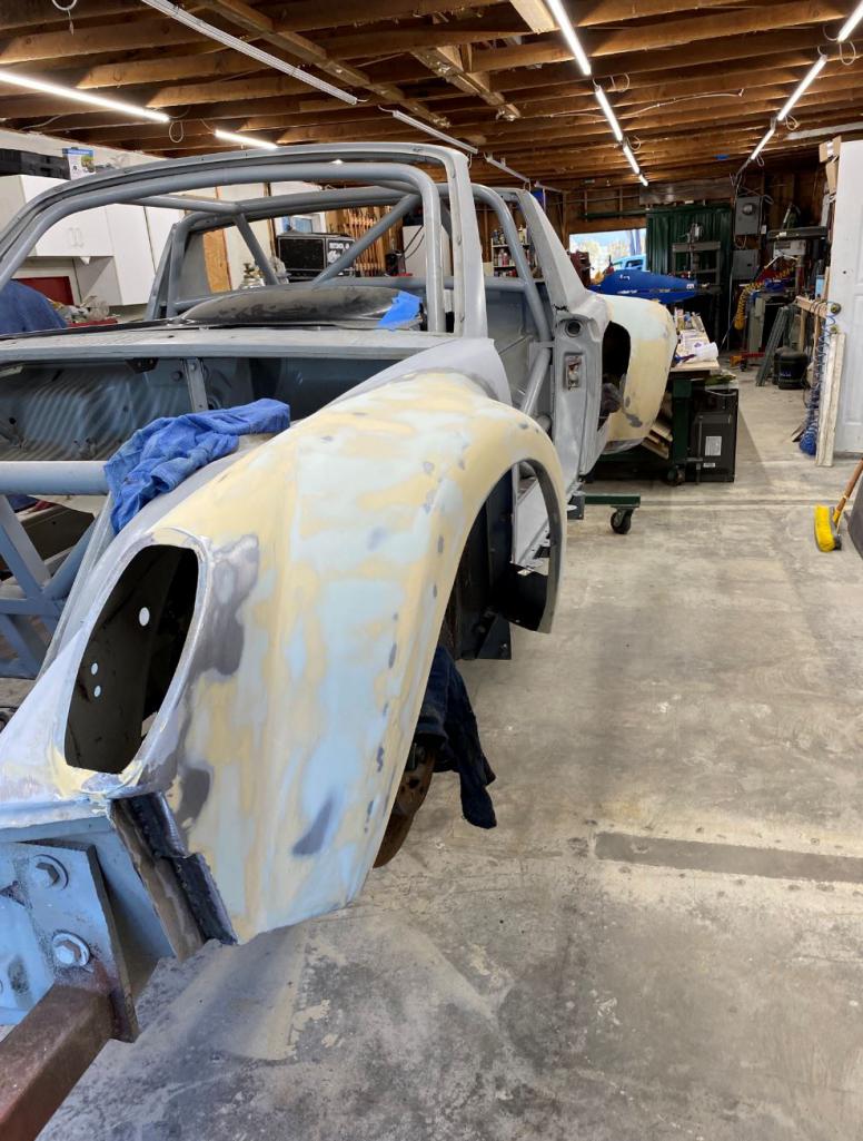
After 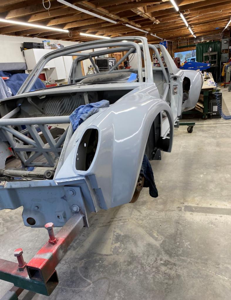
Primers 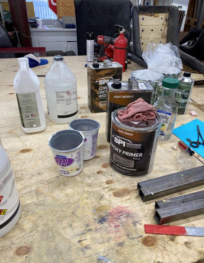
Posted by: djway Aug 2 2021, 12:00 PM
I have heard good things about SPI clear.
Looking good.
Posted by: Maltese Falcon Aug 2 2021, 05:19 PM
Rudy...your skills could put a Pebble Beach coachbuilder out of business 
Posted by: Curbandgutter Aug 4 2021, 11:45 AM
Thank you for the compliment but if they saw how the sausage was made in the back of the kitchen, they'd throw me out with a swift kick. Some of those guys are true masters..........I have to use a small amount of bondo. But I suspect that all of the painted cars have a small amount of bondo or at least high build primer.
Posted by: Curbandgutter Aug 4 2021, 01:22 PM
Just painted fenders with high build primer.
Attached thumbnail(s)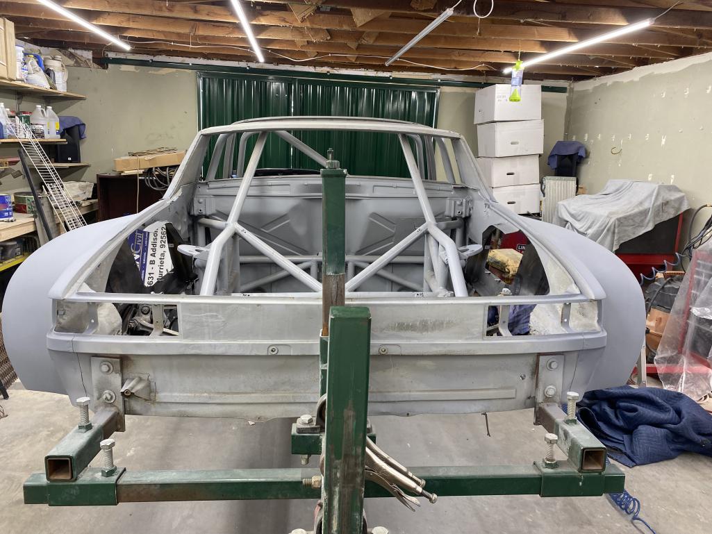
Posted by: siverson Aug 4 2021, 02:00 PM
Wow - looks really narrow in primer. Almost stock.
-Steve
Posted by: Curbandgutter Aug 4 2021, 02:21 PM
Wow - looks really narrow in primer. Almost stock.
-Steve
I would have to agree, almost stock
.
Posted by: Curbandgutter Aug 4 2021, 02:22 PM
Front has been neglected so here you go.
Attached thumbnail(s)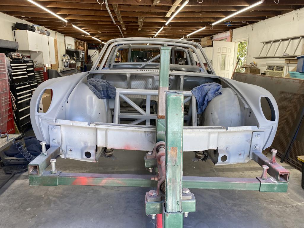
Posted by: Curbandgutter Aug 4 2021, 02:25 PM
Running boards.
Attached thumbnail(s)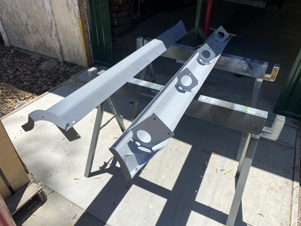
Posted by: tygaboy Aug 4 2021, 03:08 PM
No words. Well, other than these.
Posted by: Dion Aug 5 2021, 12:52 PM
This build is phenomenal Rudy. Wow. Love the outlets on the fenders, it does indeed have a 959 vibe happening there. Very cool.
Posted by: Curbandgutter Aug 10 2021, 03:00 PM
Thanks guys. Positive comments keep us going. If there was no one to share your work with it would not be as rewarding. Going to be out for a while. I’m in the middle of a fight with COVID. I’ve been completely exhausted for 5 days now. Lost smell and taste. No energy to walk to the restroom. Have to muster all I have to get up. Today odd the first day that I felt a change in the right direction. For all my brothers out there say a prayer for me.
Posted by: AZBanks Aug 10 2021, 03:12 PM
Thanks guys. Positive comments keep us going. If there was no one to share your work with it would not be as rewarding. Going to be out for a while. I’m in the middle of a fight with COVID. I’ve been completely exhausted for 5 days now. Lost smell and taste. No energy to walk to the restroom. Have to muster all I have to get up. Today odd the first day that I felt a change in the right direction. For all my brothers out there say a prayer for me.
You got it. Prayers going up for a fast recovery.
Posted by: Shivers Aug 10 2021, 03:19 PM
Prayer sent, hope you are 100% real soon. God knows the world needs someone that can create a 914 Salvador Dali Edition.
Posted by: andys Aug 10 2021, 03:44 PM
Prayers for a speedy recovery!
I just went through a radical prostatectomy last Thursday, from which I'm still recovering. Needless to say, there's no 914 activity over here.
Andys
Posted by: sixnotfour Aug 10 2021, 03:50 PM
Prayer sent, hope you are 100% soon..
Posted by: 76-914 Aug 10 2021, 04:39 PM
Damn Rudy, I almost stopped by there last Friday but I was driving the red 914 and it was getting hot outside so I went straight home. Glad that I went home instead now. I thought you already had covid several months back. Are you vaccinated? Is this the Variant? Regardless prayers sent, God Speed and if there is anything I can do for you - from a safe distance - LMK.
Posted by: FL 000 Aug 10 2021, 08:53 PM
Get better soon so you can get back on that 914. Nothing as satisfying as getting some primer on it - big milestone.
Posted by: Cairo94507 Aug 11 2021, 07:17 AM
Just an amazing build. I hope you get well soon and get back to work on this incredible car. Rest and get well.
Posted by: Andyrew Aug 11 2021, 03:01 PM
Drink lots of water and keep the positive attitude! Get better soon buddy!
Posted by: tygaboy Aug 11 2021, 05:35 PM
Rudy - You take care and get well soon!
Posted by: mgp4591 Aug 11 2021, 08:37 PM
Take care of you for now...the rest of us will have to suffer through with your previous posts for inspiration and vision! Get well soon bud!
Posted by: Krieger Aug 11 2021, 10:18 PM
Hang in there dude!
Posted by: Andyrew Aug 19 2021, 11:38 AM
@http://www.914world.com/bbs2/index.php?showuser=15637
You doin OK buddy? Lots of us are concerned that you havent logged in since the 10th!
Posted by: LefthandRev Aug 19 2021, 01:03 PM
I just caught up on all of this. This build is friggin' BANANAS.
B. A. N. A. N. A. S.
Posted by: Curbandgutter Aug 21 2021, 08:41 PM
Hey guys wow I barely made it. Had a real life and death struggle with Covid. So many were praying thank you thank you thank you. I had a direct encounter with King Jesus. I had given up the fight and was ready to die. I had been fighting for 10 days, had no appetite lost at least 15 lbs in 10 days. But God had other plans for me. Had a vision where King Jesus pulled out from the lineup. May sound weird to some but I can’t deny what I saw and how King Jesus saved me. This happened on Tuesday morning. From that point on my full appetite came back and I’ve just been regaining my strength. I’m so glad to be back.
Posted by: 76-914 Aug 21 2021, 10:08 PM
Even Jesus wants to see your build finished. Welcome back Pipo.
Posted by: FL 000 Aug 21 2021, 10:35 PM
Wow, glad you pulled through. It affects people so differently and sounds like you got lucky. Glad you are getting better.
Posted by: Blue6 Aug 21 2021, 11:14 PM
Good to hear your on the mend.
Posted by: ValcoOscar Aug 21 2021, 11:59 PM
Rudy
Thank you for the update. We all need you, but most importantly your family does too. Looking forward to seeing you back on your feet enjoying what you do....
Just FYI, you're not alone. I have a family member with long haul Covid..not fun
Stay strong my friend
Oscar
Posted by: Andyrew Aug 22 2021, 08:34 AM
Rudy, Thank you for taking the time to let us know how your doing! Were all praying for you!
Posted by: andys Aug 22 2021, 10:53 AM
Rudy, thank God you pulled through!
Andys
Posted by: Curbandgutter Sep 9 2021, 02:39 PM
Thanks everyone! You guys are all a bunch of good peeeepz. Thank you for all your prayers....and I truly mean that. I'm getting back at it as of today. Will have an update soon on the cantilever suspension.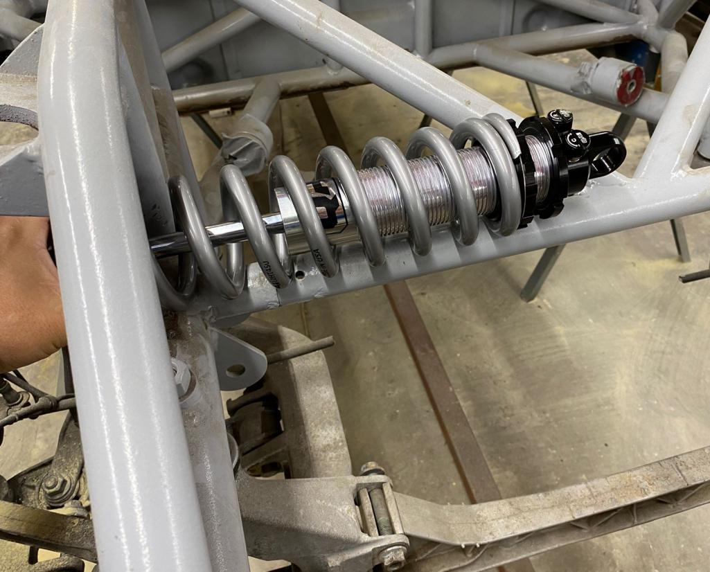
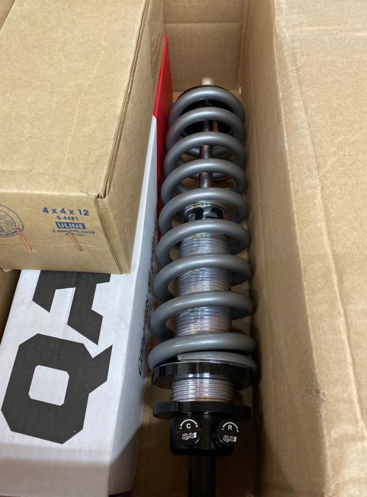
Posted by: Netspeed Nov 29 2021, 11:37 AM
Just checking in to see how you're feeling! Hope you have the energy for the build.
Posted by: Curbandgutter Dec 6 2021, 01:56 PM
Hey @Netspeed thank you for asking. I do have the energy and have been working on the car. I would like more time but I was out almost a month from Covid and had a lot of work to catch up on. I completed the fenders though, blocked and primed inside and out, the floor is primed inside and out. I’m now moving on to the suspension pieces. have them engineered now I need to install my new mill and Lathe.
Attached thumbnail(s)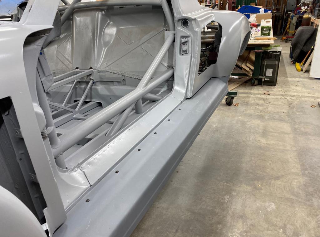
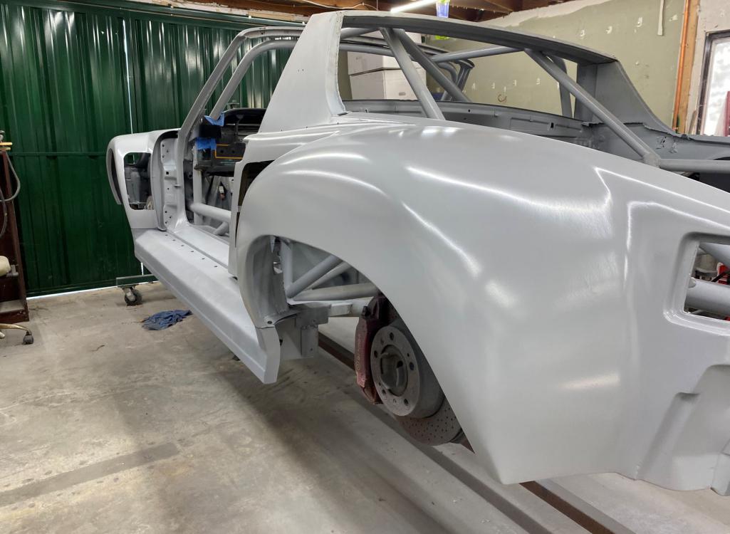
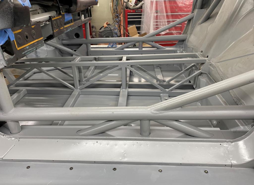
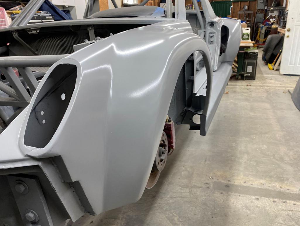
Attached image(s)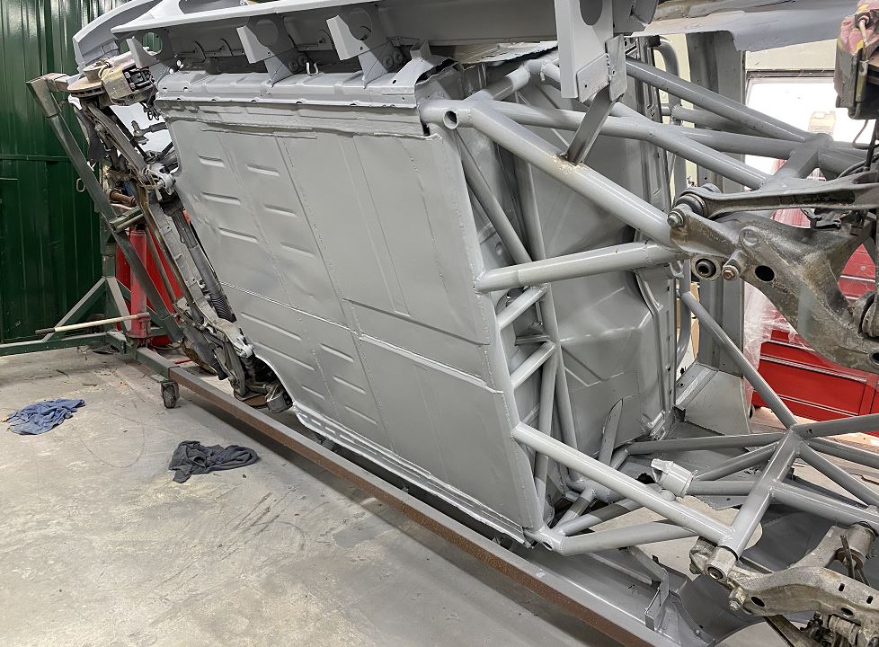
Posted by: Cracker Dec 19 2021, 08:49 AM
Damn Rudy...what a beast of chassis - its like Grp 5 all over again (but with more power)!
Impressive.
Cracker
Posted by: rgalla9146 Dec 19 2021, 04:55 PM
Rudy your car is as sick as they get.
You must stay well.
Best wishes and prayers.
Beautiful concept and execution.
An inspiration.
Rory
Posted by: Curbandgutter Dec 20 2021, 02:46 PM
Damn Rudy...what a beast of chassis - its like Grp 5 all over again (but with more power)!
Impressive.
Cracker
hey @http://www.914world.com/bbs2/index.php?showuser=11316 [u] thanks man. I can't wait to drive this thing, but I'm currently setting up my mill and lathe so that I can get on with the bell crank suspension.
Posted by: Curbandgutter Dec 20 2021, 02:47 PM
Rudy your car is as sick as they get.
You must stay well.
Best wishes and prayers.
Beautiful concept and execution.
An inspiration.
Rory
Thanks @rory[u]
Posted by: porschetub Dec 20 2021, 03:00 PM
Rudy your car is as sick as they get.
You must stay well.
Best wishes and prayers.
Beautiful concept and execution.
An inspiration.
Rory
what a beast,built like a tank ,great skills here.Pleased to here you are recovered ,good luck.
Posted by: Curbandgutter Mar 21 2022, 12:39 PM
QUICK UPDATE:
Seats came in. Posted a couple of pictures for comparison. The Recaros use std 914 seat sliders. They slide and recline as well.
The suspension pieces are engineered and are being machined.
RECARO POLE POSITIONS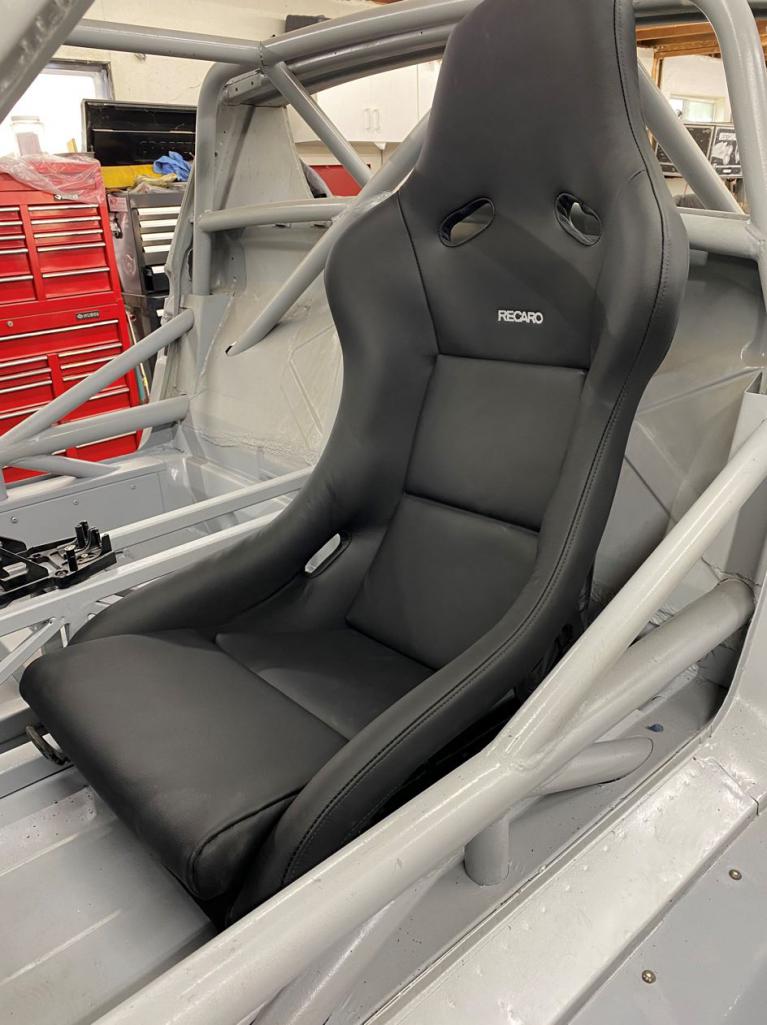
OBVIOUS STOCK ONES 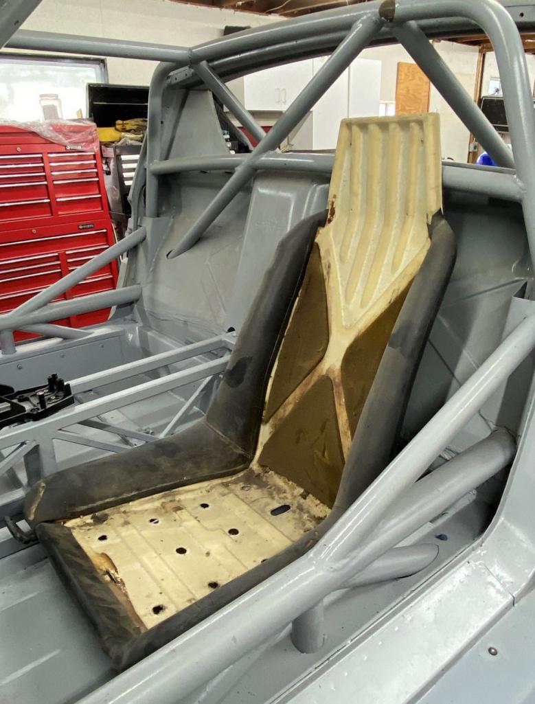
SEATS I HAD BEEN PONDERING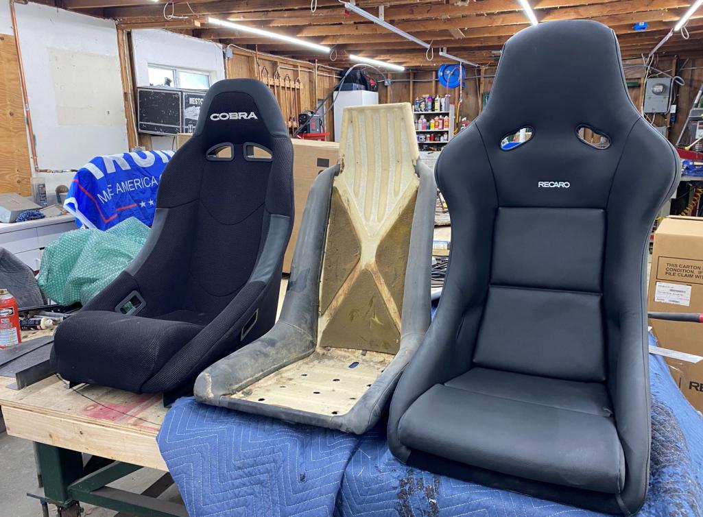
Posted by: Curbandgutter Sep 30 2024, 04:19 PM
Hello everyone, it has been a while. I've been busy with selling our home and playing architect on our new home. I wanted to give an update that the car will be using a flat 6 gt3 motor with the wiring harness, computer and tach. Will be providing updates as soon as it is delivered. Really excited about this one since now it will be all Porsche flat six with a manual and a 9000 rpm redline. Cheers.
Posted by: FL000 Sep 30 2024, 07:12 PM
Glad to hear this project will be moving forward again - I was wondering about it recently. That motor is going to be nuts and on par with the rest of the build
Powered by Invision Power Board (http://www.invisionboard.com)
© Invision Power Services (http://www.invisionpower.com)