Printable Version of Topic
Click here to view this topic in its original format
914World.com _ 914World Garage _ Gauge Lighting
Posted by: timothy_nd28 Jun 10 2013, 12:27 AM
This is a tribute thread for the late Al Garcia, RIP
Many of us have issues with the inadequate lighting on our gauge cluster. This is a tutorial on how to increase the lighting for the DIY'er and for under 20 bucks.
Euro911 was nice enough to be the guinea pig, in which he donated his gauges for this build. I rate the skill level at around a 3. 1 being easy (adding blinker fluid) and 10 (setting up valve geometry).
1st step, remove the combo/speedometer/tach from your car. Alrighty, easy enough. 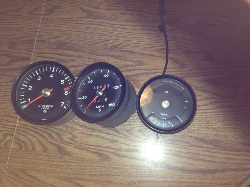
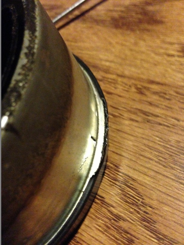
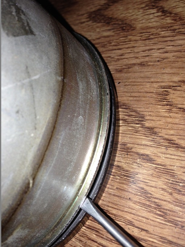
2nd step, drink a beer or two. This is somewhat unnerving and for the few it may turn you off. However, this isn't all that bad. We need to remove the bezel trim rings. I'm sure there is a machine out there that cost 15k, that will do this in about 10 seconds but we will use a small screwdriver. The first time I did this (my gauges) it took around 40 mins each, and I had a good size blister on my index finger. You will get a feeling that you are absolutely ruining these rings, but your not. Wedge the screw driver in between the bezel and the gauge can. Once your in, lightly twist back and forth the screw drive in situ pushing in a forward direction. By the time you get to the third gauge, you'll be a pro! I also found that it is unnecessary to uncrimp the entire circumference of the bezel ring. Once you get 3/4 around, the last 1/4 will pop off. 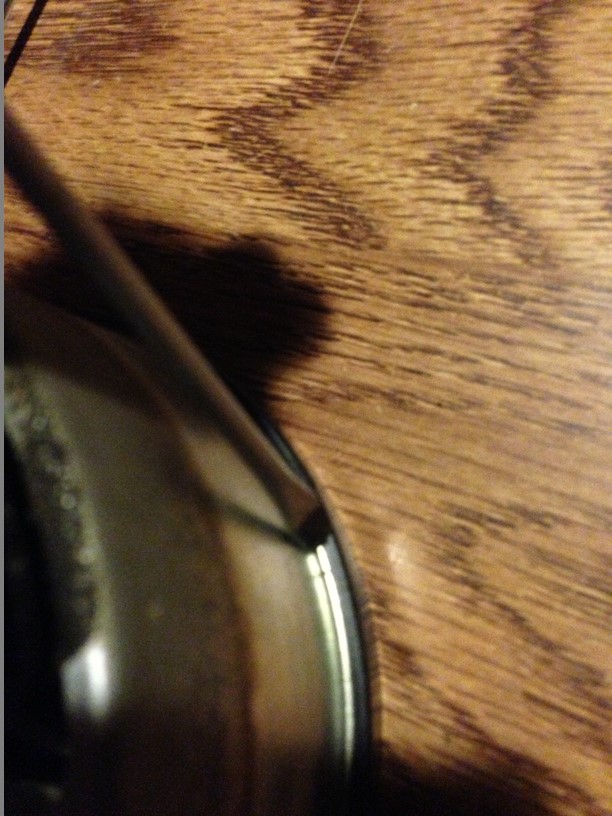
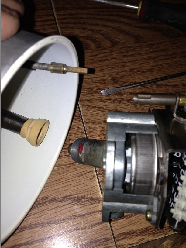
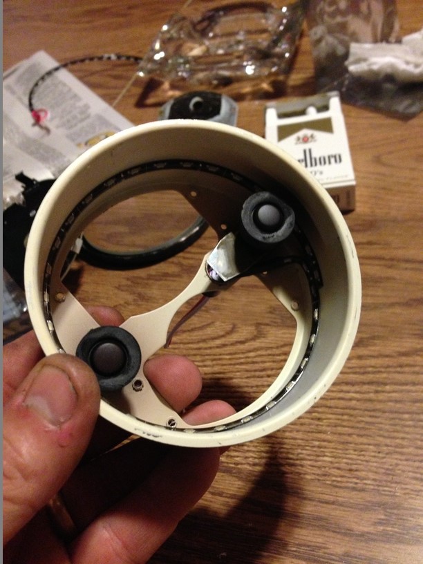
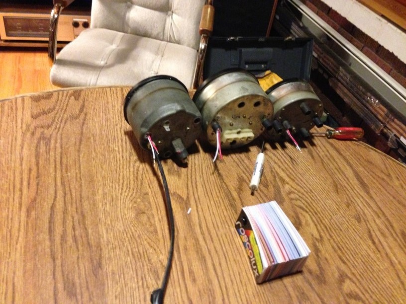
Now that these ring are off, go ahead and remove the insides. The tach will have 4 brass screws and the odometer will have 2. The combo gauge will have either 4 or 8 screws depending on the year.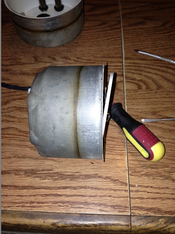
Now that the inner guts have been removed, you should have 3 empty cans like this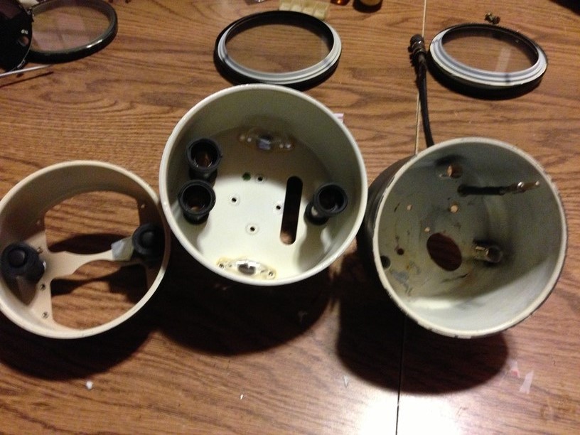
We will need to clean the inside of these cans, for the best adhesion of the LED lights in a future step. I didn't use anything special, good old windex spray should suffice.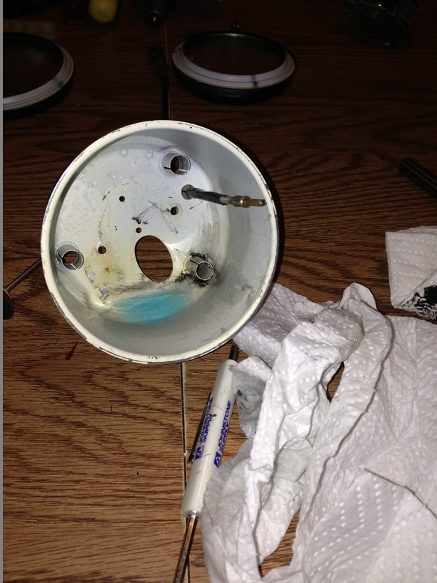
Posted by: timothy_nd28 Jun 10 2013, 12:27 AM
Since the inside guts are out and very accessible, this is a great time to perform some house keeping to sprucen them up.
This looks pretty shitty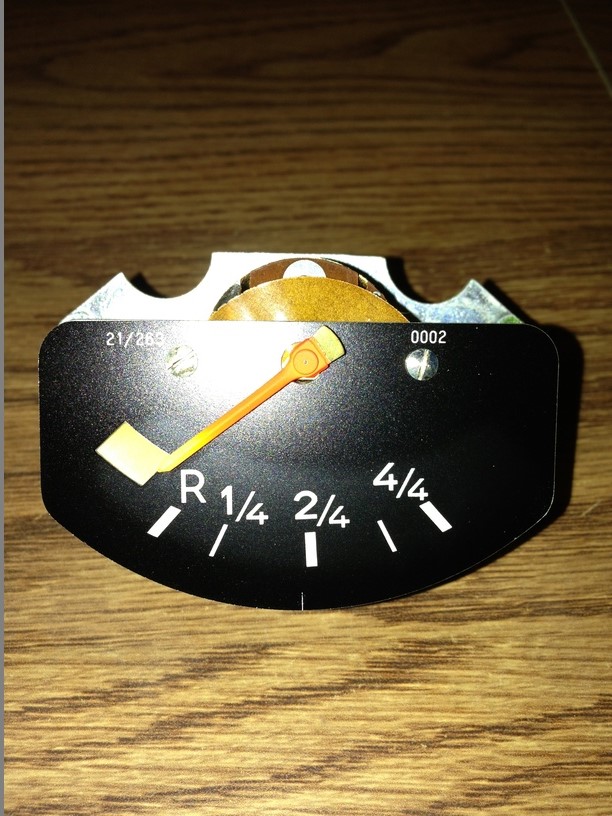
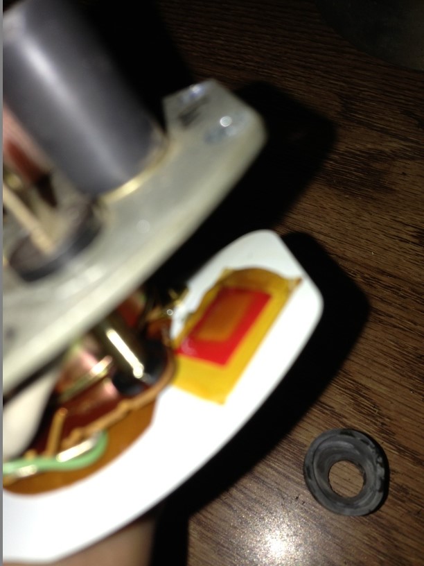
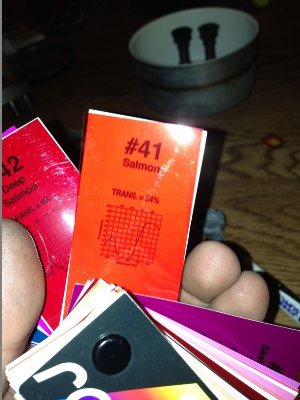
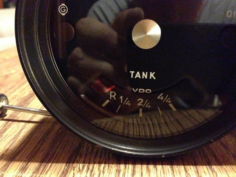
Notice the sun bleached needle and reserve fuel light window. This is resolved by purchasing a 3 dollar film gel swatch book.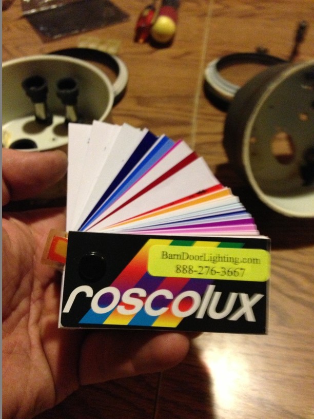
Many colors to choose from. Euro911 mentioned that these gauges came from his wife's car, so I was tempted to use pink. 
Some skillful scissor work and some masking tape, it is to my liking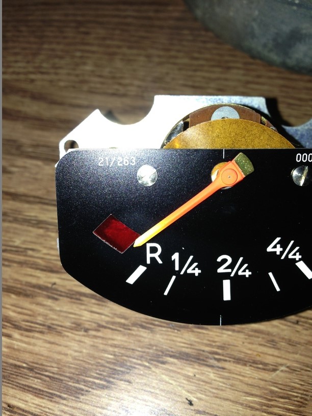
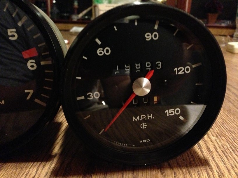
Another thing to consider while these are accessible is painting the needles. Refer back to the picture from step one, the needles are faded. Obtain a bottle of this. This bottle came from Corvette Central, but the color is very close to ours. 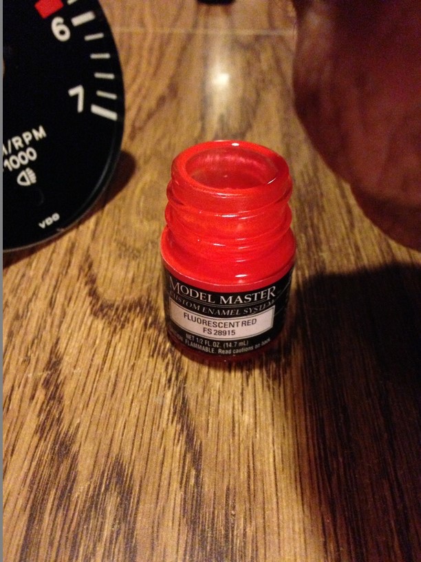
Take your time when painting them needles. I'm very pleased how these turned out.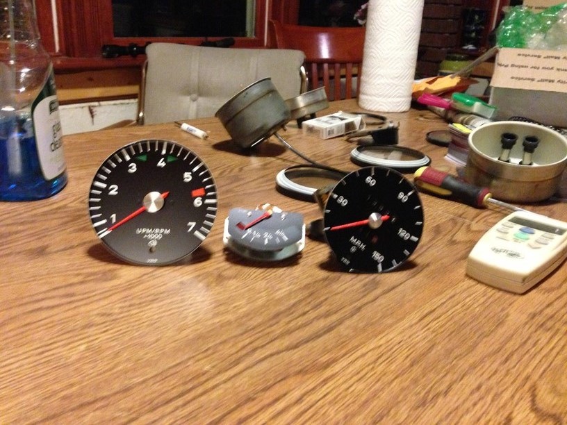
Posted by: timothy_nd28 Jun 10 2013, 12:28 AM
Towards the LED's, there is a plethora of styles, shapes, and colors to choose from. For mine, I picked white side emitting led's on a flexible strip with adhesive style sticker. http://www.ebay.com/itm/1-Pcs-60cm-335-SMD-White-LED-Flexible-Strip-Side-emitting-60-LEDs-/181132106216?pt=LH_DefaultDomain_0&hash=item2a2c5099e8
This is 60 cm long, and around 9 dollars each. You will need 2 of these to do all 3 gauges. By chance the above link doesn't work in the future, the spec for these LED's is 60cm long 335 SMD white LED flexible side emitting 60 led's. I choose this over others, because its side emitting, water proof, and high density of LED's per inch vs others I have seen. 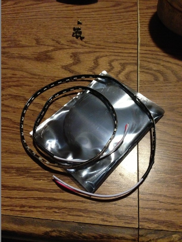
Okay, grab the speedometer can as we will start with this one. This is the largest of the 3 gauges and will utilize one of the two led strips you just bought. The flexible strip will have a white line on every 3rd led. This is where you're supposed to cut the strip. Make sure you cut exactly on this white strip, or you will render the LED strip useless. Mock up the LED flex strip so it wraps around the inside of the gauge. Once you have a good idea on total length, go ahead and cut it.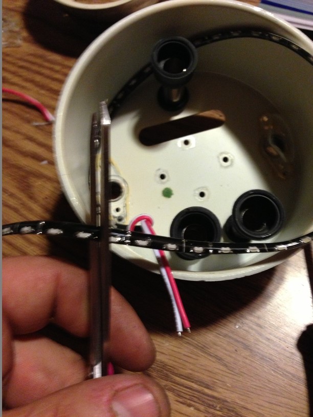
Next, tie a little knot in the wire, like this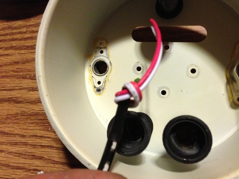
This knot will help act as a strain relief for the wire
Go ahead and remove the sticker backing, and attach the LED strip. The wires must go thru the original light tube, and the knot must be inside this tube. Also, VERY IMPORTANT, these led strips are directional. Make sure these leds are facing forward before sticking them down!!! I typically install these strips about a 1/2" from the back of the gauge can. 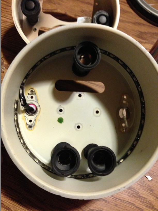
With the wires going thru the original light tube, take some clear RTV and squeeze some into the hole. This will keep the wires anchored, and you'll have less chance of ripping them out in the future. 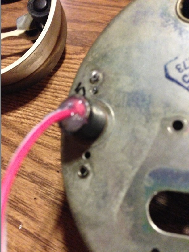
More house keeping, go ahead and clean the glass or plastic lenses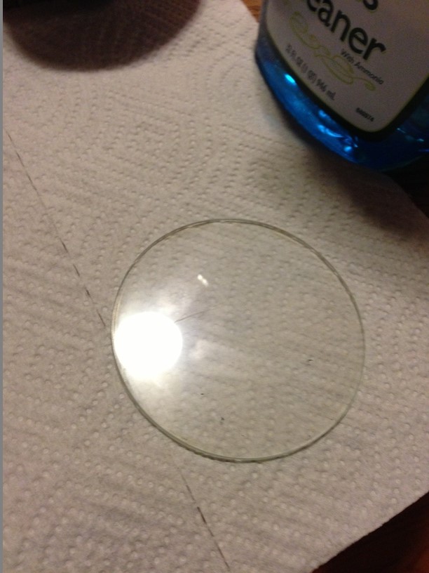
Posted by: timothy_nd28 Jun 10 2013, 12:28 AM
Step 2 made me forget to take pictures of reassembly, for that I apologize. After these LED strips are installed, go ahead and reassemble each gauge. You will need to hook in the bezel ring (the small area that you didn't uncrimp) and pop in the rest. With your screw driver, carefully push down and re-crimp the bezel to the gauge can. This step is pretty straight forward.
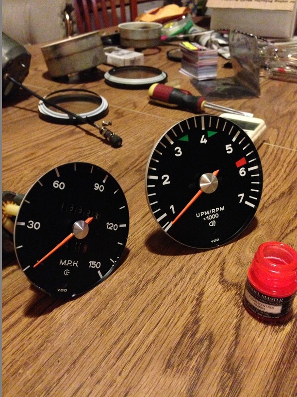
This is what it should look like after reassembly. Notice the pretty color on the needles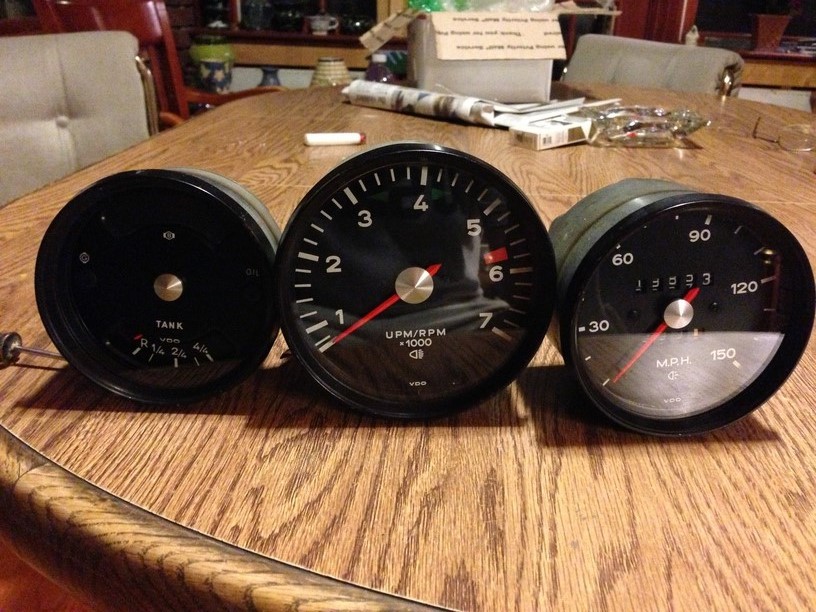
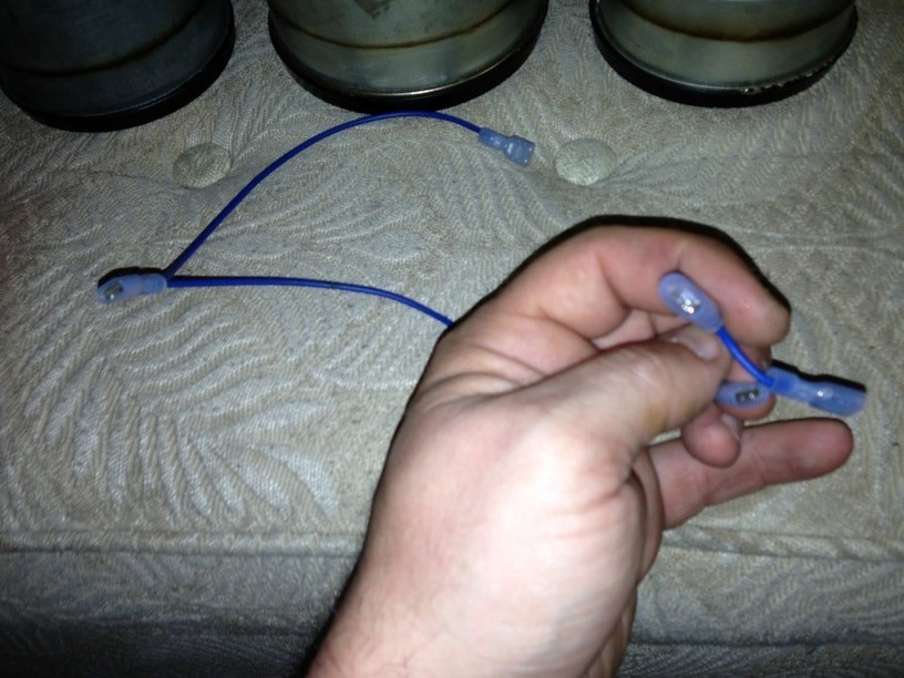
Now onto the wiring. We need to build a harness to jumper all the grounds together. You should have a brown wire that ties to the combo gauge, so we need to splice into this, without cutting wires. 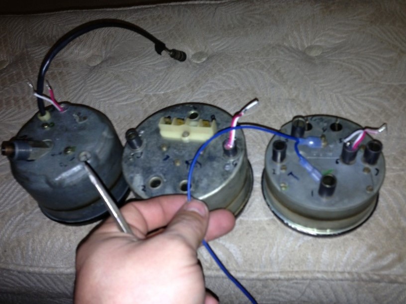
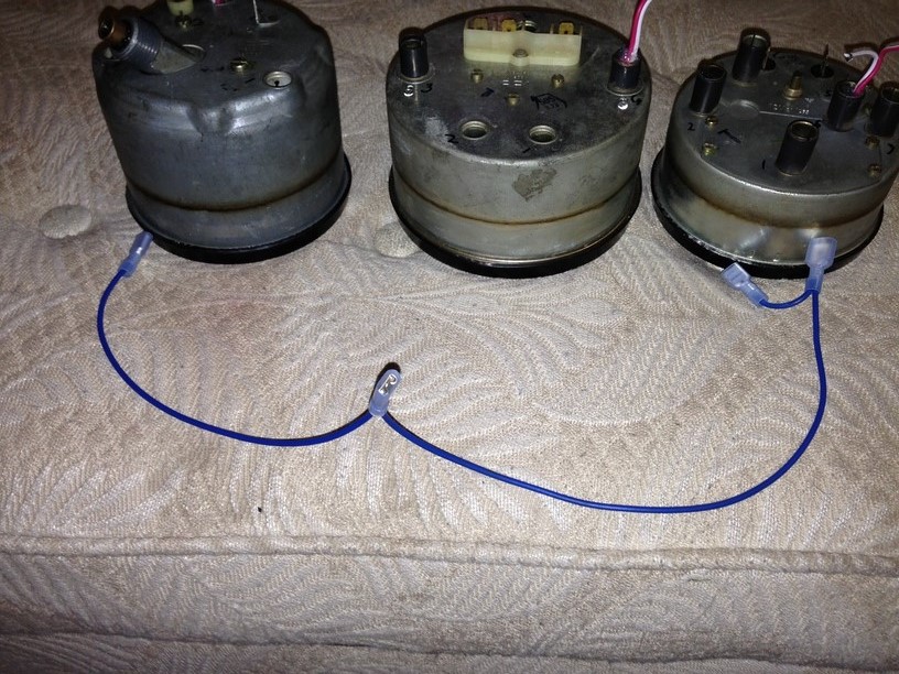
I should of used brown wire instead of blue, but this is all I had laying around. Obtain a piece of wire about 20" long or so. On one end, add a insulated 1/4" female terminal. Going from that terminal you just installed, move in about 10" and add another 1/4" female terminal. The opposite end of the wire gets abit squirrelly. We need to add 2 more female terminals and a male terminal (see picture). The male terminal will plug into the car's brown ground wire. The female on that end will plug onto the gauge where the brown used to go. This leaves you with 3 female terminals on the harness you just made that will plug into the (white) wires on the LED flex strip. White is ground on this flex strip, whereas red is positive. 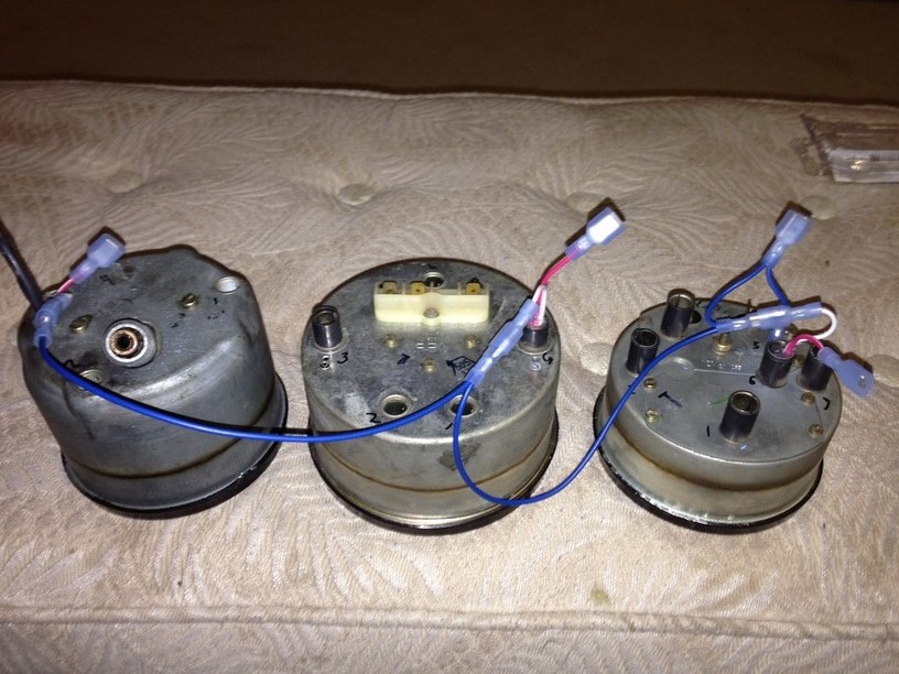
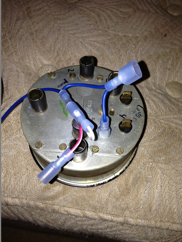
Towards the wires from the led flex strip (protruding the light tubes) you'll need to add male 1/4" insulated terminals to all the wires. This will mate with the harness you made with the car's electrical connectors. This makes for a pretty clean install. Keep in mind that the white wires are negative (ground) and the red are positive (+12vdc)
Here is a diagram borrowed from Jeff Bowlsby's website to help aid with re-installation. 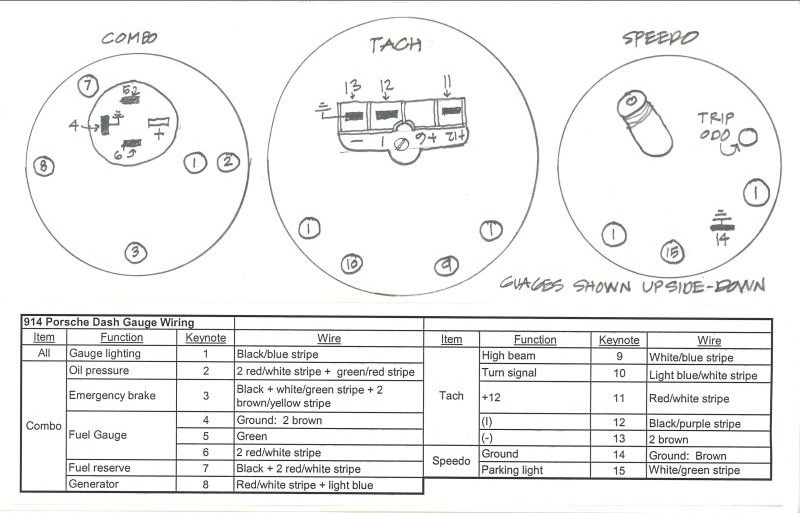
Posted by: timothy_nd28 Jun 10 2013, 12:29 AM
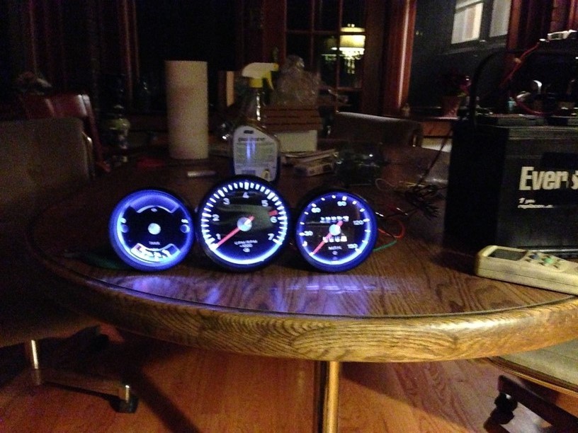
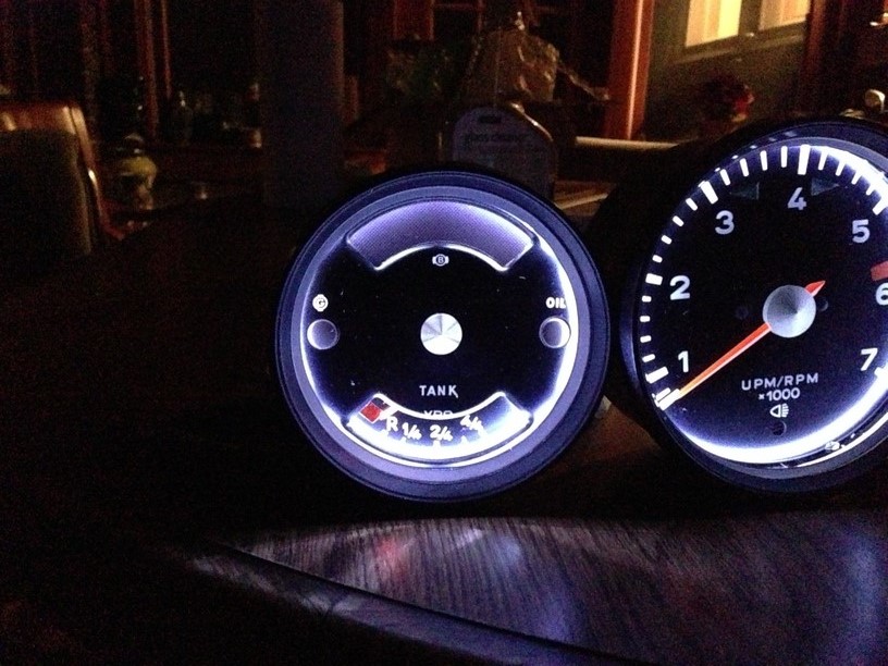
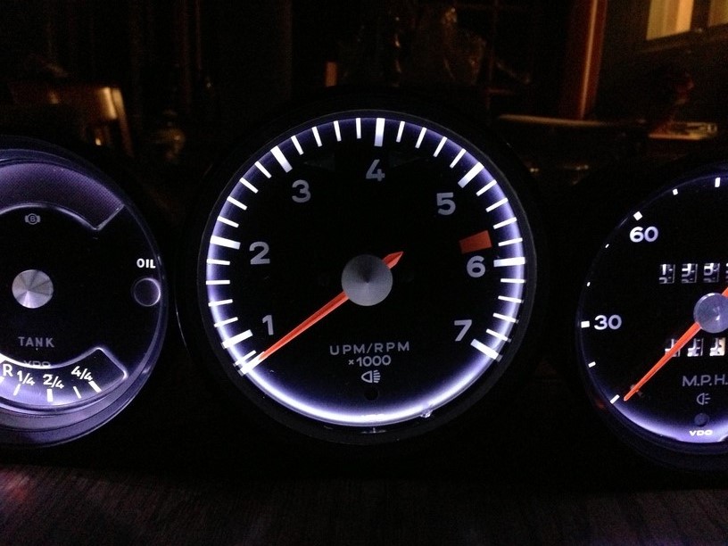
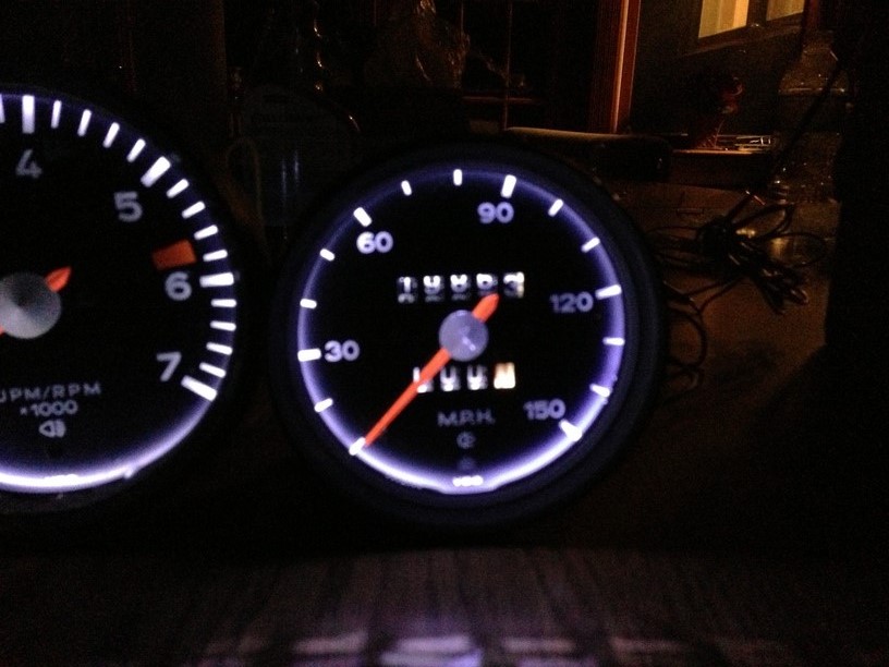
Here is the finished product. The camera made the pictures turn out abit blueish, however in person they look great and bright white. Using the car's stock rheostat, you can dim these down to a point, before they quit and go dark. Surprisingly they do dim down quite a bit. No need to add a PWM controller. 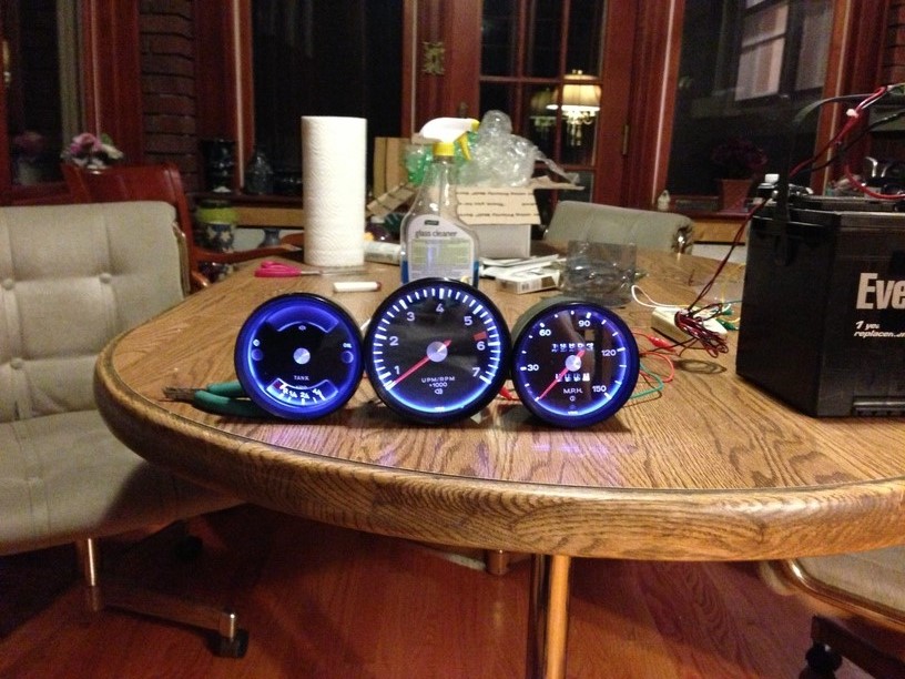
Hopefully you guys aren't intimidated with this project. The results will give you instant gratification. 
In the near future, I'll do a write up on Al's famous multi color gauges.
Attached image(s)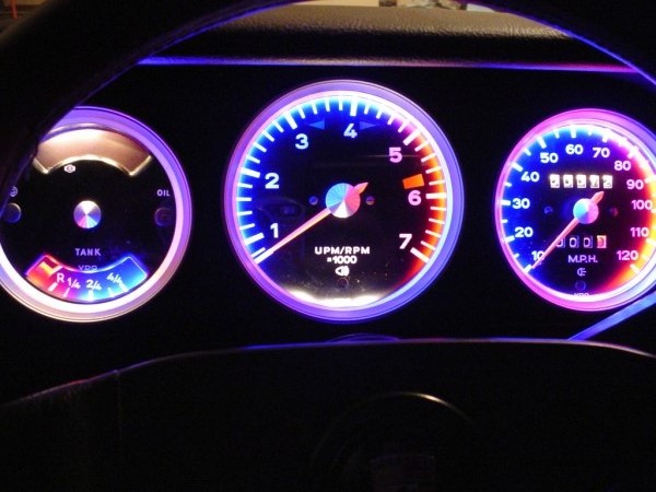
Posted by: r3dplanet Jun 10 2013, 12:38 AM
![popcorn[1].gif](style_emoticons/default/popcorn[1].gif)
Posted by: bulitt Jun 10 2013, 01:54 AM
Thx for posting this!
Posted by: Chris H. Jun 10 2013, 08:59 AM
Amazing work Tim! Thank you for the very detailed description. 
For anyone with later gauges you can also change the plexiglass (plastic) lens out for glass. Don't recall what year they went to plexi...'74 maybe? Pretty much eliminates the scratches permanently.
Posted by: 76-914 Jun 10 2013, 09:20 AM
Al would be proud of you.  Now throw those cigarettes away before we have to place you next to Al. FWIW, I believe Al had a bunch of that stuff along with some gage and gage bodies. If your interested PM me and I'll check with Shirlee.
Posted by: ellisor3 Jun 10 2013, 09:34 AM
Great Tribute Thread. Al was a great guy, helped me get my gauges back together and even adjusted my speedo. Sorry he is gone.
Posted by: mrholland2 Jun 10 2013, 10:22 AM
While my car is down, I would love to see the multi color method!!
Posted by: mrholland2 Jun 10 2013, 10:27 AM
Oh, and are there LED instructions for the blinker indicators? Light/Bright light indicators? Oil/Generator? and Low Fuel?
Or do we have to stick with the old timey wimey light bulbs?
Posted by: Spoke Jun 10 2013, 10:36 AM
Good write up.
Put this in the Classics Forum.
Posted by: turk22 Jun 10 2013, 12:55 PM
very nice write up!
Still scares the shat outta me.... 
Posted by: poorsche914 Jun 10 2013, 03:51 PM
Thanks for the write up. I have been planning to replace the plastic lenses in my guages with glass. The LED upgrade looks easy enough that I will do that as well. Might wait for the multi-color writeup, though 

Posted by: timothy_nd28 Jun 10 2013, 10:33 PM

Oh, and are there LED instructions for the blinker indicators? Light/Bright light indicators? Oil/Generator? and Low Fuel?
Or do we have to stick with the old timey wimey light bulbs?
I'd stick with the old timey wimey incandescent light bulbs. The light port tubes for these lamps direct most light straight thru. The resistance on the LED lamps are not the same as the incandescent bulbs, and could cause a problem with the flasher module. On my car, I did replace the indicators lamps (minus turn signal indicator). I wasn't impressed at all, as there was no noticeable difference between the LED vs the stock lamps.
My next project will be the multi color setup, I will need a set of gauges from someone that is willing to let me try. I would also like to try a gauge setup with RGB led's. This would enable you to change the lighting to any color you can think of. The catch is finding a controller that turns on the RGB led's when power is applied to the controller. All controllers I've seen so far requires you to push the "on" button on the remote control for the LED's to turn on, this would be annoying. When you pull the headlight switch, you want the back lighting to come on with the headlight switch, not some silly remote control. So the search continues for the right controller.
Posted by: euro911 Jun 11 2013, 02:13 AM
Wow. No, I mean WOW!
I really didn't know what to expect - they look awesome Tim!
I need to fix the ODO gear when they arrive back here, but Tim wants me to install them and post some pix so we can all see what they look like installed. Since Dianne's car is torn apart, I guess I'll have to install them in the 'BB" for now 
Send me your your Pay Pal info ... you are NOT getting away with doing these for nothing 
Posted by: pcar916 Jun 11 2013, 05:47 AM
The catch is finding a controller that turns on the RGB led's when power is applied to the controller. ... So the search continues for the right controller.
Arduino microcontroller. You can make it trigger on any input you wish.... geez even temperature, vibration, ambient light conditions, whatever sensor you want to trigger on and with delay control as well. If you're ok with some breadboarding, this can run nearly the entire secondary electrical system.
http://en.wikipedia.org/wiki/Arduino
Cheap and many sources for both hardware and tutorials.
Good luck
Posted by: Steve Jun 11 2013, 11:53 AM
Thank you very much for posting this!!
I just bought the exact same paint at Hobby Lobby.
My glass is scratched on a couple of my gauges. Is there a way to buff it out or where can you get new glass??
Thanks for the help!!
Posted by: Madswede Jun 11 2013, 01:53 PM
This is a shoo-in for the "Classic" forum. Well done sir! 
Posted by: SUNAB914 Jun 11 2013, 02:00 PM
Man, that is nice and I sold my cars/parts to Bill.
UUGGG!
Posted by: Mr.242 Jun 12 2013, 09:47 AM
This is a tribute thread for the late Al Garcia, RIP
2nd step, drink a beer or two.
Auuuugh, no wonder I couldn't do this task. I was doing step #2 first and then getting stuck.

All seriousness...I will be doing this. I want to have lights that are updated and bright. Ebay purchased this am; however, it might have to wait until a winter project when the car isn't being driven.
Nice write up!

Posted by: timothy_nd28 Jun 12 2013, 01:36 PM
Hey guys I have an idea for the next build. Same idea, with the white back lighting, however when you reach the redline on the tach, all the 3 gauge backlighting would switch from white to red. I think this is very doable but it may change the skill level from a 3 to a 4 scale for the DIY'er.
Questions: Is this worth doing? Should all the gauges turn red at 5500 rpm or should it be a lower rpm? Does anyone know the pulse frequency at 5500 rpm?
Posted by: bperry Jun 12 2013, 11:15 PM
I re-did my '74 gauges (tach and speedo) back in the late 80's
I repainted the needles and cut out new glass for the tach.
I was surprised that the tach used a plastic lens.
I have a few words of caution when painting the needles.
Make really sure that the paint on the needles is really really fully dry before
you re-assemble the gauges.
Perhaps even hit it with a heat gun a little bit to cure the paint.
The problem I had was that soon after I put the gauges back in and
the temperature got HOT here in Texas, the needles on the tach and
speedometer started sticking to the resting post and they finally
got permanently stuck.
It SUCKED!
I had to fully disassemble the gauges to free
the needles.
I ended up heat curing the paint a little bit and puting a tiny bit
of vasoline on the post to prevent any future sticking.
So far so good....
What really sucked about the speedo is that I already had to
open it up twice before.
- Once to fix the odometer to get it to work again.
- A second time because when I was puting it back together
for the odomenter fix, the original paint on the tip of the needle chipped off.
(originally I wasn't planning on re-painting the needles)
-- bill
Posted by: bandjoey Jun 12 2013, 11:47 PM
Does it help to paint the can inside? White? Silver? Doesn't matter?
U made this look so easy I'm going to try it.
What did u ask for at the glass company?? Any special type? Thickness?
Thanks
Posted by: Rob-O Jun 13 2013, 08:14 AM

I measured the glass and it seems to be a nominal 1/8" thick. I went to a glass place but they wanted $28 for each piece. I suppose I should check other places but I also wonder if one can cut th glass themselves.
Also, has anyone seen the LED's in a 'warm white' color? I think that may look more original while providing the added brightness. I just don't know who carries the warm white color (I didn't see it in the 'store' on the eBay link).
Posted by: Rob-O Jun 13 2013, 08:21 AM
Oh, three other points. When I restored mine (minus this cool upgrade), I used a 'Testors' red color paint I found at a hobby shop (Hobby Lobby here in Texas) for the needles. It was a Chevy something red and dries quickly. Also, since I didn't want to spring for the glass at $28, I used a "Mother's" headlight restoration kit from Autozone to polish the plastic lenses. They came out great/perfectly smooth and clear, but you can still tell that they're not glass. Lastly, for the low fuel red cover that is faded, I used a red colored 'tab' from a hanging folder. You can find them at Staples or other office supply stores. Works perfect and looks good when the bulb lights it from behind.
Posted by: timothy_nd28 Jul 2 2013, 02:40 PM
![]() This thread corresponds to my near future partII thread
This thread corresponds to my near future partII thread
Posted by: scotty b Jul 2 2013, 05:50 PM
This thread still isn't in the classics forum ?

Posted by: timothy_nd28 Dec 4 2013, 06:59 PM
Does it help to paint the can inside? White? Silver? Doesn't matter?
U made this look so easy I'm going to try it.
What did u ask for at the glass company?? Any special type? Thickness?
Thanks
Re-reading thru this, I forgot to answer your question. I have noticed that many gauge cans are already painted white inside. However, thru the years they have yellowed. Other cans are not painted at all, so I would recommend painting or repainting the inside of the gauge can while you are in there. You will need to use extremely flat white spray paint for the best results.
Posted by: gothspeed Dec 5 2013, 08:50 AM
Simply amazing!!!!
Thank you for posting
Posted by: PThompson509 Dec 9 2013, 10:08 PM
Oh, and are there LED instructions for the blinker indicators? Light/Bright light indicators? Oil/Generator? and Low Fuel?
Or do we have to stick with the old timey wimey light bulbs?
www.superbrightleds.com has replacement bulbs for the blinkers and such - they work ok, but you really have to get the polarity right, otherwise they just don't work. Lots of colors to choose from - I went with blue and it's quite nice.
I measured the glass and it seems to be a nominal 1/8" thick. I went to a glass place but they wanted $28 for each piece. I suppose I should check other places but I also wonder if one can cut th glass themselves.
Also, has anyone seen the LED's in a 'warm white' color? I think that may look more original while providing the added brightness. I just don't know who carries the warm white color (I didn't see it in the 'store' on the eBay link).
Glass cutting isn't the problem - it is cutting the glass then tempering it - try going to a stained glass shop and see what they can do (bound to be a LOT cheaper).
As for the colors, check out the above website - I really like the stuff that superbright has, and have used them extensively for lots of projects - like a 3rd brakelight that sticks to the chrome just below the roof.
Cheers, Peter
P.S. Excellent job on the LED strips in the can!
Posted by: john77 Feb 12 2015, 08:32 PM
Finally got all the parts to start this great DIY project. One gauge down, two to go. Compared to the new LEDs on the speedo, the old bulbs on the tach don't even look like they're on.
Posted by: euro911 Mar 5 2015, 12:25 AM
... and almost 2 years since Tim upgraded a set of gauges for me (the ones you saw him modify in this very thread), I finally installed them into a panel and applied power to them. These gauges are actually for my wife's '71, but I thought I'd try them out in the 'BB' until her car is ready for them 
These are sitting on my work bench right now and illuminated with 14 volts from a DC power supply. 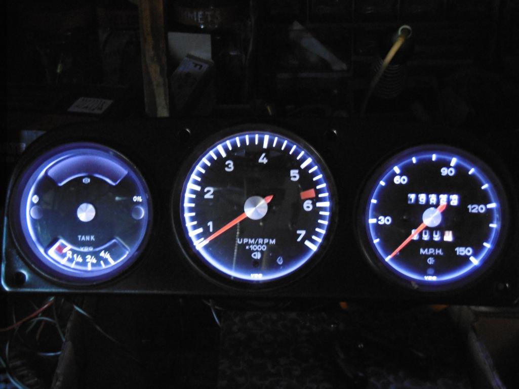
They shut off at approx 9 volts and at 10~11 volts, they're very pleasant to look at, so I'll adjust the dimmer control to achieve that illumination setting after they're installed in the car.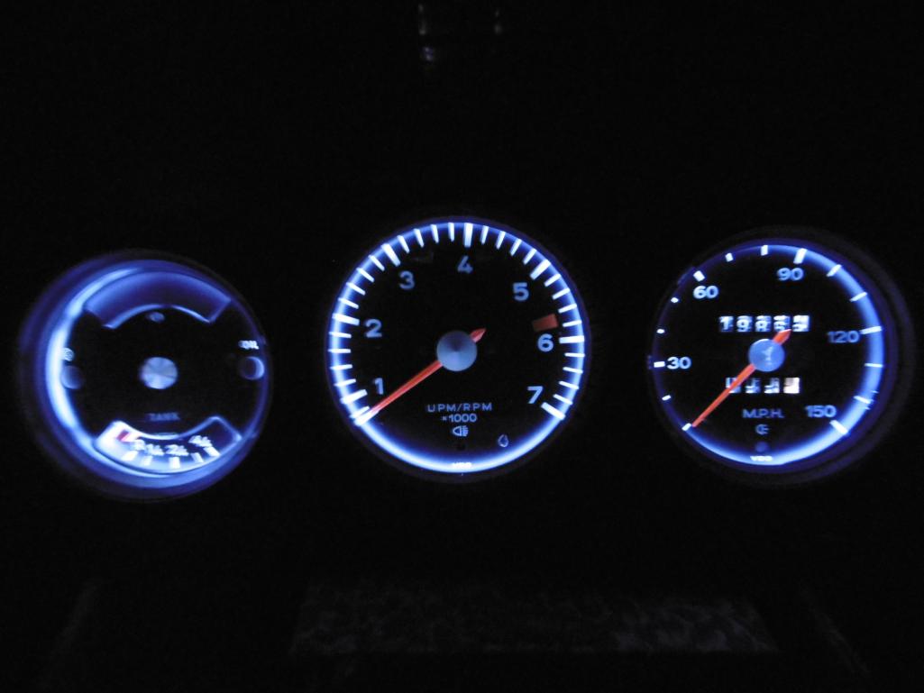
Thanks again, Tim ... I'll finally be able to see these at night
Posted by: Cuda911 Mar 5 2015, 02:44 AM
Great work!!!
Regarding replacing the regular bulbs with LEDs, see Post #156 in my thread:
http://www.914world.com/bbs2/index.php?showtopic=237472&st=140
There are also two links in that post that have short video clips showing the difference in brightness between the original bulbs and LEDs.
Not nearly as good an improvement as the mod in this thread, but relatively easy to do.
Posted by: euro911 Mar 5 2015, 08:41 PM
I swapped out most of the incandescent bulbs with LEDs several years ago. They helped somewhat, but still not good enough for my tired eyes.
The LED strip lights are so much better - there's just no comparison 
Posted by: rnellums Mar 5 2015, 08:45 PM
I'm really pumped. My Next-Gen LED gauges are arriving from Tim tomorrow!!!
Powered by Invision Power Board (http://www.invisionboard.com)
© Invision Power Services (http://www.invisionpower.com)