Printable Version of Topic
Click here to view this topic in its original format
914World.com _ 914World Garage _ initial Valve train try
Posted by: jmargush Jun 22 2013, 06:21 PM
I ran the first try for my valve train geometry and I need some input or votes of confidence!
9590 Cam from Raby
Waiting on my adjustable push rod tool and shim kit (in case I need it).
So I just put in the stock push rod and cycled the intake valve.
Spec lift is to be .426 and I got .4365 which is within the 5% rule.
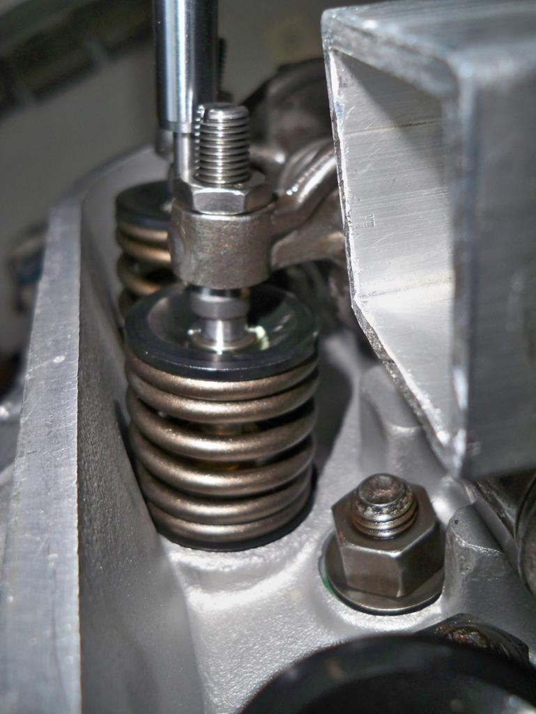
So I cycled it back to half way open and here is what the adjuster to valve looks like.
is this good or do I need to play with push rod length?
Any input is appreciated.
Attached thumbnail(s)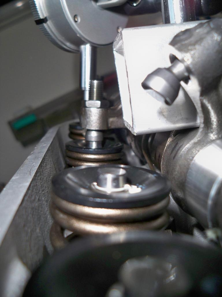
Posted by: pilothyer Jun 23 2013, 12:54 PM
As far as I can tell, by looking at the picture, the geometry looks to be correct and should keep your valves and guides happy.
Even if the original pushrods give you favorable results, you should consider using the steel pushrods anyway. You will have a quieter more efficient valve train. .............."It's all in the combination" . 
Posted by: malcolm2 Jun 23 2013, 01:10 PM
Raby's directions worked for me. measure 2 or 3 times...cut once. Your pix look good.
Posted by: stugray Jun 23 2013, 02:05 PM
looks pretty good.
The hardest part in the instructions is determining what is "straight".
Just out of curiosity.. what does your cam card card say for both "cam lobe lift" & "valve lift" - Intake & exhaust.
My first cam card showed only lobe lift & I had to figure out what valve lift was supposed to be by myself.
Stu
Posted by: jmargush Jun 23 2013, 07:53 PM
I am definitely going to use the chrome molly pushrods I was just trying these while I was waiting for the adjustable one to show up.
Cam Card calls out Valve lift .426 both exhaust and intake. doesn't say anything about lobe lift
Posted by: jmargush Jun 24 2013, 08:03 AM
How did you guys go about cutting your pushrods?
Cut a little long and grind to finished size?
Posted by: malcolm2 Jun 26 2013, 09:36 AM

How did you guys go about cutting your pushrods?
Cut a little long and grind to finished size?
Used a copper tube cutter. Very small increases in wheel depth and a couple extra wheels, then some filing, light sanding. Bought a 24" long mic from Harbor Freight too.
Posted by: stugray Jun 26 2013, 10:05 AM
If I remember correctly, I clamped the pushrod in a vise and used a hacksaw.
The vise was used as a guide for the saw.
I cut a little long and used my bench sander to fine adjust.
I also bought the 24" HF calipers.
Then I had a some teflon blocks I used to pound the ends in.
Stu
Powered by Invision Power Board (http://www.invisionboard.com)
© Invision Power Services (http://www.invisionpower.com)