Printable Version of Topic
Click here to view this topic in its original format
914World.com _ 914World Garage _ Final (I hope) engine wire questions
Posted by: lsintampa Jul 2 2013, 10:28 AM
75 914/4 2.0
Coming off of the FI wire harness is a branch (near the dizzy area) with a red, white, green/red, and black wire.
1) The red and black are marked by PO as going to the coil. I assume red to the positive side, and black to the negative side. But I want to make sure so that's more a question.
2) I'm not sure where the green/red wire goes. There is a temp sensor (or some sensor) that is top side near the dizzy. I think that green/red goes there?
3) Almost sure that the white goes to the AAR.
Finally there is a bundle of white wires coming off near the transmission. They all have large eye connectors and I assume them to be ground wires - even though they are white. I attached them to one of the tranny / motor mount bolts.
Posted by: gunny Jul 2 2013, 10:37 AM
You are correct with all of the white wires as grounds and you connected them corectly.
Posted by: malcolm2 Jul 2 2013, 10:50 AM
Resources are everywhere.... try this one:
http://bowlsby.net/914/WiringHarnesses/HarnDia_FI_GC.jpg
If that is not right try this page and scroll down to find your car:
http://bowlsby.net/914/WiringHarnesses/HarnDia_FI_GC.jpg
Sorry I have L-jet, but it is tuff to figure too.
Clark
Posted by: lsintampa Jul 2 2013, 11:59 AM
Took a picture.
I've looked at the wire diag and just about all else. Maybe I'm just dense, but I don't see where the colors on my harness match up to any diagram.
So here's a picture of what I'm talking about. The PO did label stuff, but the two blue tapes (one on the red wire and the other on a thicker black wire) say they go to the coil. I just do know if they both go to positive, negative, or one to each.
This is what I'm trying to figure out. Right now the only wires to the coil are the power wire from the center of the dizzy and the green condenser wire to the negative side of the coil.
The green / green-red wire is going to the oil sender. The white to the AAR.
Thanks,
Len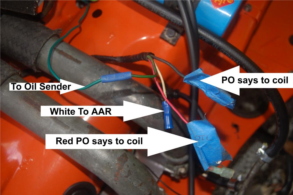
Posted by: ThePaintedMan Jul 2 2013, 12:22 PM

So here's a picture of what I'm talking about. The PO did label stuff, but the two blue tapes (one on the red wire and the other on a thicker black wire) say they go to the coil. I just do know if they both go to positive, negative, or one to each.
This is what I'm trying to figure out. Right now the only wires to the coil are the power wire from the center of the dizzy and the green condenser wire to the negative side of the coil.
The green / green-red wire is going to the oil sender. The white to the AAR.
Thanks,
Len
Len,
It's very likely the PO replaced part of the harness at one point or another. The only way to find the original wire colors would be to find where he patched the harness by opening up the tubing around it.
I would say that the black is now the tach negative signal and the red is 12v coil power. I don't know about FI since I've never had it, but the AAR guess with the white wire sounds right. You could test for resistance in the black wire by finding where it plugs into the tach. If you get any kind of a reading with the multimeter, then at least that one is correct. I think that's supposed to be black and purple originally.
The green (originally green/red) is for the oil pressure sender. And that about does it for the extent of my wiring knowledge.
Posted by: Jeff Bowlsby Jul 2 2013, 12:22 PM
That is the ignition harness, not the FI harness. The red wire is not factory stock...from your description, it sounds like the PO may have modified it, doing an internal wire repair inside the casing. Take teh tape/casing off to find the splice. The black and red likely do go to the coil, but check the continuity of each wire back to the 12 pin connector on the relay board to verify its circuit, compare it with my harness diagram that shows wire numbers...that will tell you which wire goes where on the coil.
Posted by: Tom Jul 2 2013, 12:49 PM
I am with Jeff here. Verify where the wires go on the 12 pin connector. That will tell you for sure where the wires are supposed to go. I would also hunt for the splices the PO made and check them out. At this point you don't know what quality of splices he has done and how they have held up. Just follow the harness back to a bulge, that is where the splice will be.
Tom
Posted by: lsintampa Jul 2 2013, 01:09 PM
OK, traced them back to the 12 point connector on relay board.
Pin 1 is the green/red wire
Pin 5 is the red wire
Pin 7 is the black wire
Pin 12 is the white wire
Now back to find that diagram and see if I can figure this out.
IDK, I've never seen one of these puppies before. As far as I knew they were the original color.
Thanks,
Len
Posted by: lsintampa Jul 2 2013, 01:14 PM
Well the green/red and white were correct.
I have to question why the black (pin 7) and red (pin 12) are the colors that they are, but hey it's copper inside.

But then again the big fat (new) positive cable for the battery is black.
I'm gonna double check those red and black wires just to be sure. The pin numbers are stamped on the female 12 pin plug, so I'm sure they are correct.
Thanks all,
Len
Posted by: lsintampa Jul 2 2013, 01:33 PM
That is the ignition harness, not the FI harness. The red wire is not factory stock...from your description, it sounds like the PO may have modified it, doing an internal wire repair inside the casing. Take teh tape/casing off to find the splice. The black and red likely do go to the coil, but check the continuity of each wire back to the 12 pin connector on the relay board to verify its circuit, compare it with my harness diagram that shows wire numbers...that will tell you which wire goes where on the coil.
Very good and thanks!
I'm off to find pinout wire colors for the high beam relay now. PO pulled it and left the wires hanging. I know they are original wires, but there are four wires and five connectors, so that'll be fun. Me thinks something is jumped.
Posted by: Tom Jul 2 2013, 02:41 PM
Pin #1 is for the oil pressure sender, normally green/red
Pin #5 is for the tach signal - goes to coil neg, normally black/purple
Pin #7 is for coil hot- goes to coil positive, normally black/red
Pin #12 is for the AAR. normally white
Tom
Powered by Invision Power Board (http://www.invisionboard.com)
© Invision Power Services (http://www.invisionpower.com)