Printable Version of Topic
Click here to view this topic in its original format
914World.com _ 914World Garage _ Marcus' Corvair conversion
Posted by: r3dplanet Jul 10 2013, 10:50 AM
A few years back I got all excited about doing a Corvair engine conversion for my 1971 car. The project waffled. Numbers were crunched and chewed. Thought and diagrams and opinions were drawn out over long winter evenings.
One particularly rainy winter evening, I found an ad on Craigslist advertising a warehouse full of Corvair parts including engines. So my pal Rory and I drove a hundred miles into the boonies late one rainy night to what turned out to be an unmarked, geographically isolated, former slaughterhouse illuminated by a single 60 watt light bulb. No cell phone reception, no escape. We were met by a couple of toothless brothers who couldn't stop talking about Daddy. Seemingly they only did what Daddy wanted them to do. Daddy wanted them to sell the stash of Corvair parts. Daddy wanted them to steal my Toyota cargo van. Daddy needed to approve the transaction of cash for an engine. Daddy, it turned out, was long dead. The two brothers kept trying to separate Rory and I, and the creepier of the two brothers kept demanding my car keys so he could test drive my van, despite my insistence that it wasn't for sale. For the first time in a long time, I wish I had a tazer gun on me. The brothers eventually showed us exactly what I wanted - an RD code 1965 110HP engine. Fearing for our lives, Rory and I muscled the engine into the van while the brothers went to find more stuff for Daddy to sell to us, or you know, maybe a club or some rope or a ball gag or something.
I left the $100 on the bench and tore the hell out. Rory and I laughed all the way back to town, ever so pleased that we were neither killed, nor raped, nor eaten. Plus, we were one up on a Corvair engine.
So with a provenance like this, and seeing JRust's new car, Dr. Evil's project, and 914coops Nader's Nightmare all take shape I've finally decided to get serious about my own project: the VW-Porsche 914-C6.
The "C" stands for Corvair.
Posted by: computers4kids Jul 10 2013, 11:21 AM
I will be looking forward to your build thread  loved the story of picking up the engine. What hp are you expecting to achieve? I get the idea of keeping an air cooled engine and the simplicity. These cars a lot of fun when you get in the 200+ range.
Posted by: r3dplanet Jul 10 2013, 12:55 PM
Right. My goals are straightforward. Since my 914 is essentially a weekend fun car, and thanks to the Portland weather, it means that the car is only driven for a few warm months of the year for fun weekend drives. The key word there is fun. Primarily I'm after reliability, very low maintenance, silent valve train noise, and excellent power. All in that order.
To that end I'm going with the VW Type-1 94mm piston and cylinder "big bore" conversion that takes the displacement from a stock 2.7 liters to 3.1 liters. The Type-1 cylinders are much better than the stock Corvair cylinders given the better construction, cooling, and floating pin arrangement. The engine will be rebuilt as a reverse rotation "140" motor meaning that I'll ditch the 110 heads for the better 140 heads. I'll use ARP studs and bolts for the case hemispheres and connecting rods for better strength. I'm also using a hardened and nitrided crank from the turbo motor. I haven't decided on a fuel system just yet, but I know I'll start with a four-into-one intake and single carburetor which is just fine for warm weather driving. Eventually there will be an EFI system, but first things first. I'm hoping for a true brake horsepower of 130-150. I may go nuts with headers and a roller rocker assembly. I'll skip the turbo. For reasons outlined elsewhere, I just don't think that the primitive turbo with its ponderous lag is a good match for a 901 gearbox.
The plan is to build up the motor, mount it on a frame and get all of the adjustments and initial tuning before installing it in the car. Like all of my projects, this will take forever. Patience, patience.
Posted by: bandjoey Jul 10 2013, 01:01 PM
That place was featured in Texas Chainsaw Massacre 
Ill enjoy watching the build. 
Posted by: Steve Jul 10 2013, 01:22 PM
Could of also of been the "home" episode of the X-Files. Good thing there was two of you.
Posted by: r3dplanet Jul 10 2013, 01:36 PM
For your viewing pleasure, some barfy pics of the tear down so far.
Here's part of the reverse rotation assembly. A custom 130 tooth flywheel, an engine to gearbox adapter plate, and an Otto-20 reverse rotation hot cam. Needed still are the reverse distributor gearset and alternator pulley.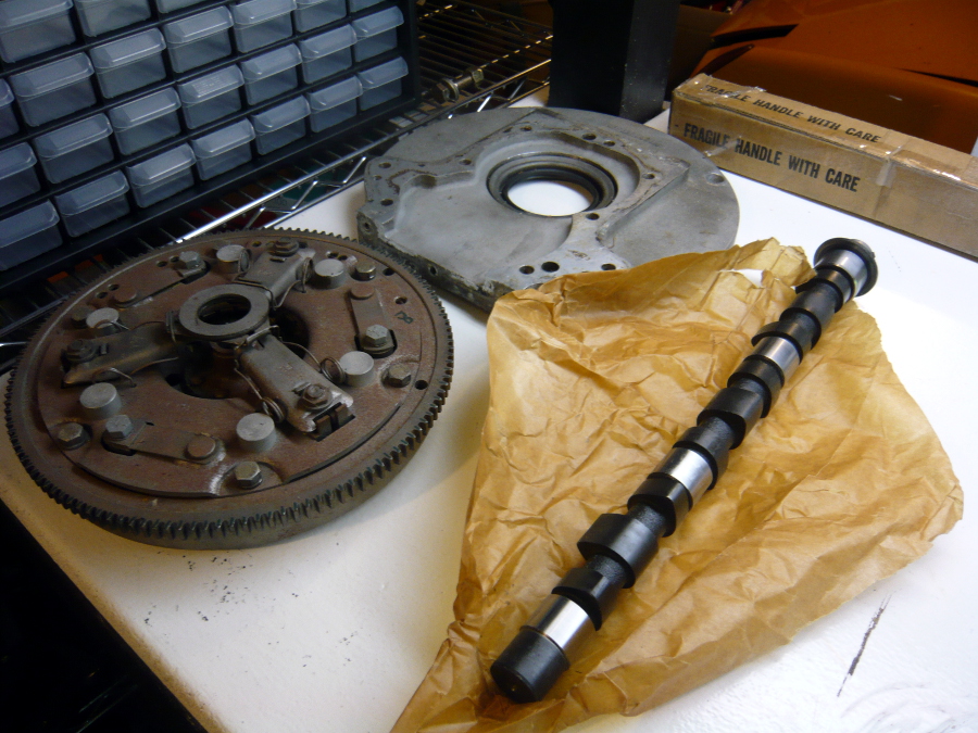
And here's the engine as-is, right from the bottom of the Black Lagoon.
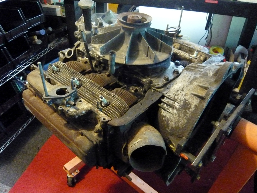
The first thing to do is to gather 25 bins from Ikea for $4.99 each to separate and label everything. Then disassembly. To start, the magnesium fan and pulley is removed, followed by the top cover.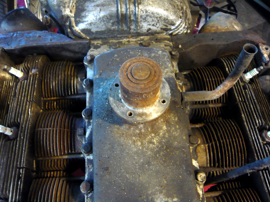
Under the cover is another cover, or really a very big gasket.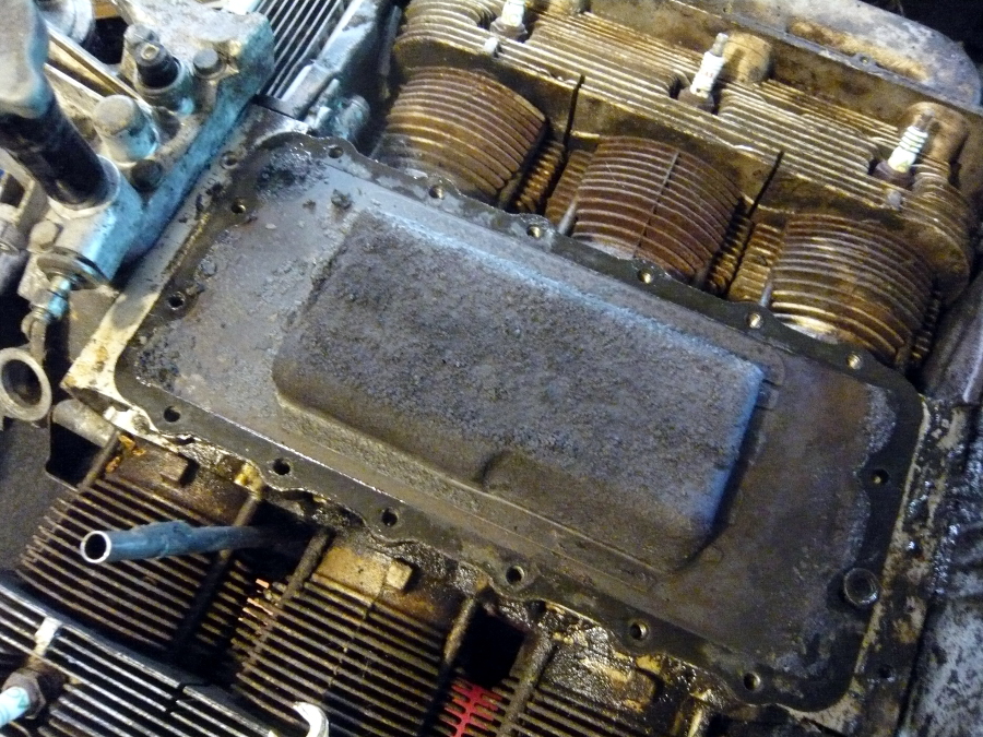
Under that gasket is another gasket, which when removed reveals the slimy innards of the crank case.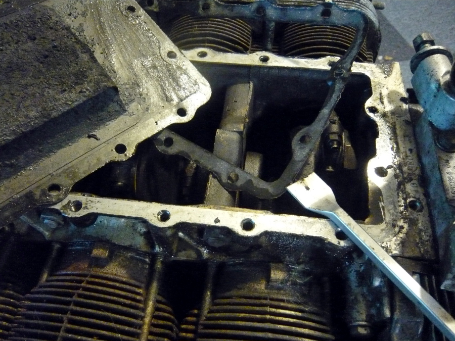
Note. Since I'm reversing the motor and mounting in "backwards" into the car, for the sake of 914 terminology I'll henceforth switch the terms "front" and "back" from what GM people would use. On the front of the engine there's a aluminum assembly that houses the oil filter, oil pressure sender, and speedo cable. Six bolts and it pops off easily.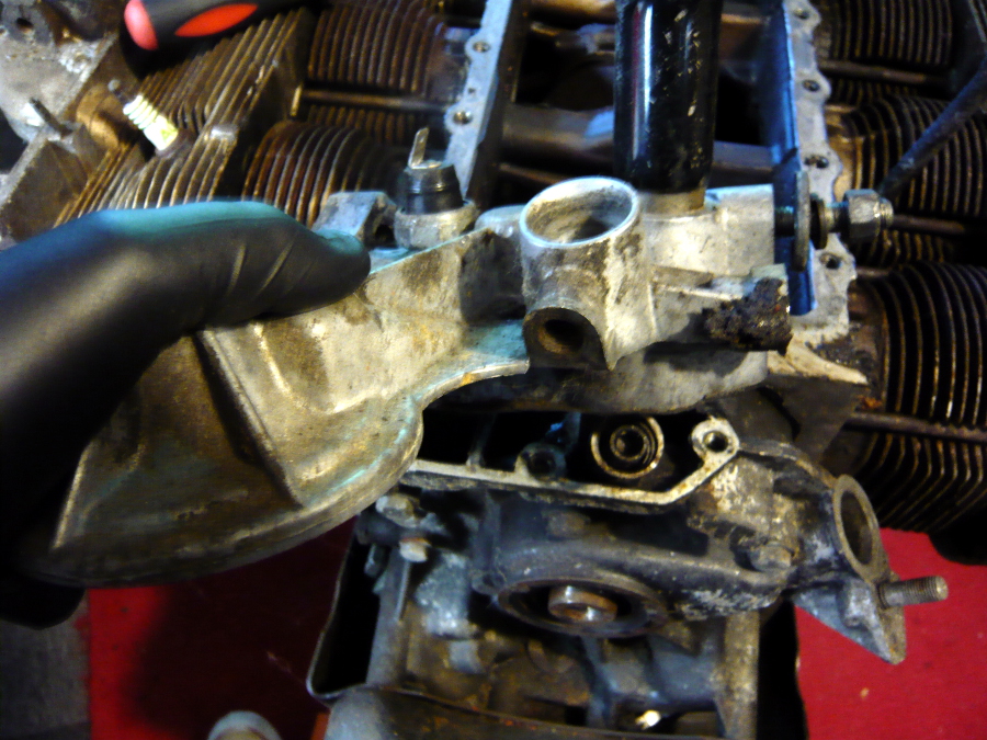
Then the oil cooler.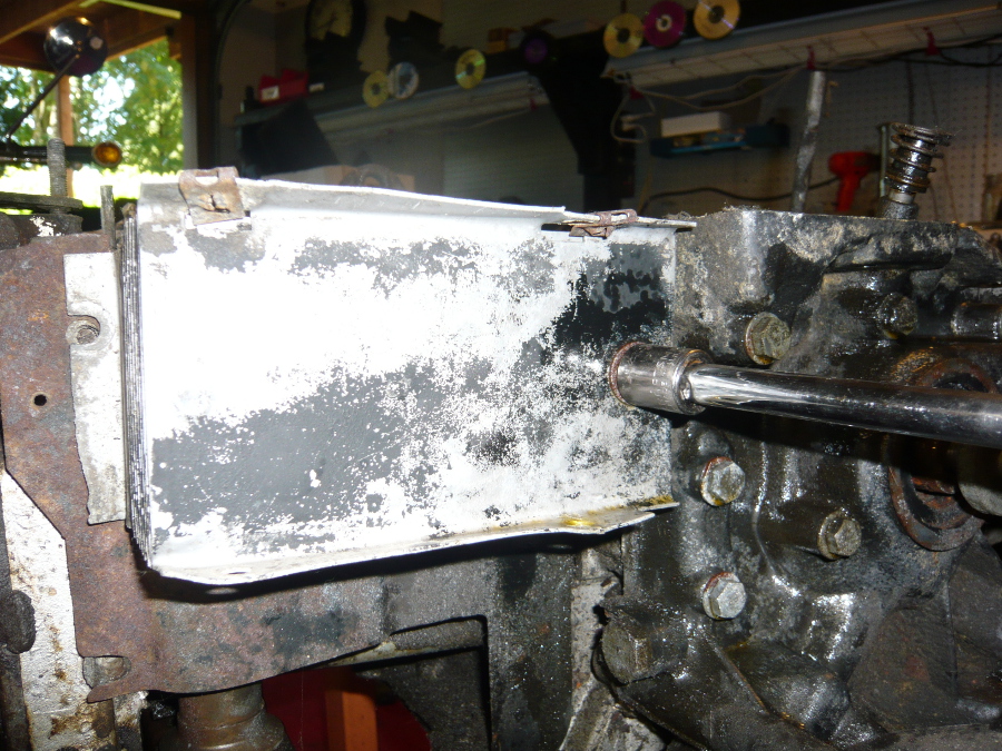
And finally the front engine cover which is held in with seven bolts and several nuts holding the bottom plate / front engine mount. 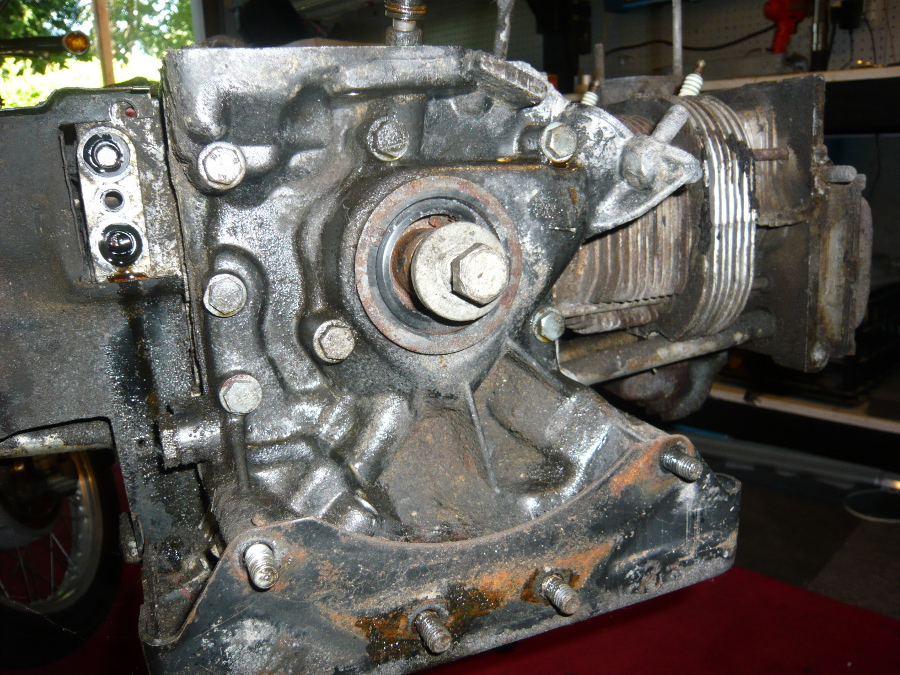
Posted by: r3dplanet Jul 10 2013, 01:54 PM
That front engine mount plate is the bearer of mysteries and a handy place to keep an assortment of extra fasteners and probably some chewing tobacco.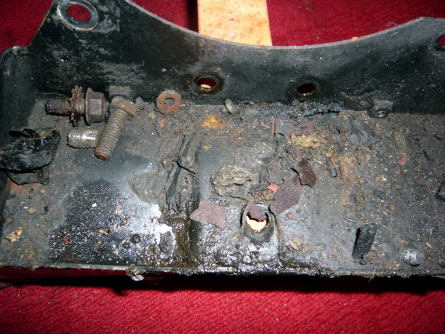
The valve covers on the later engines like mine are held on with four bolts and these elongated strips of metal to spread the load. Apparently this makes for an excellent seal.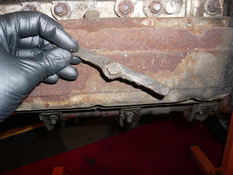
The head for cylinders 1-3-5 showing its glorious hydraulic rockers. The nuts that hold the rockers down thread onto special studs that double as the nuts for the lower head studs. You can see the upper head nuts and they are RUSTY. It took a few days of Kroil, swearing, and heat to remove them. But hey, they held their torque.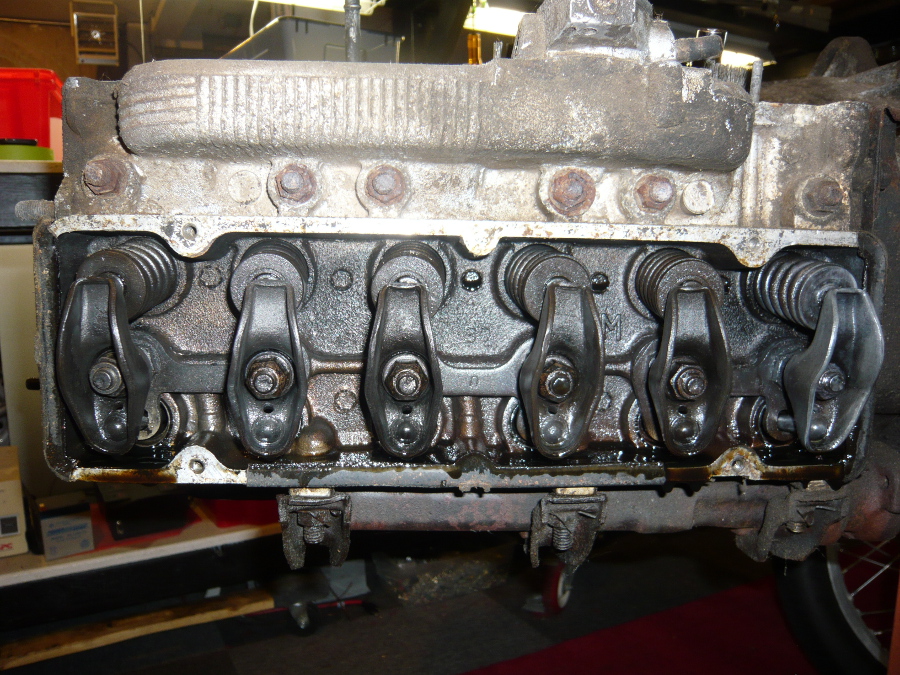
The engine is missing most of the sheet metal tins, but I'll cross that bridge when I get to it. But what little there was removed easily.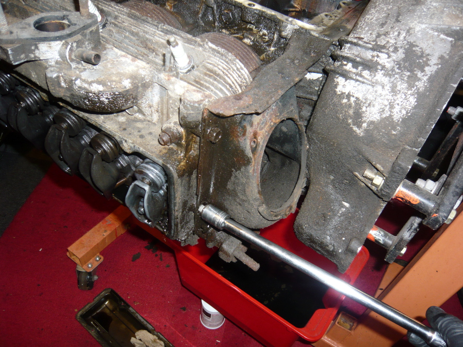
Three nuts hold the exhaust log. Once removed, it popped right off. This design uses no gasket.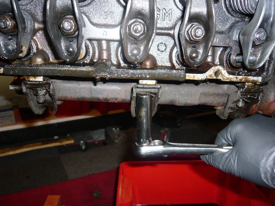
Off come the bottom head nuts.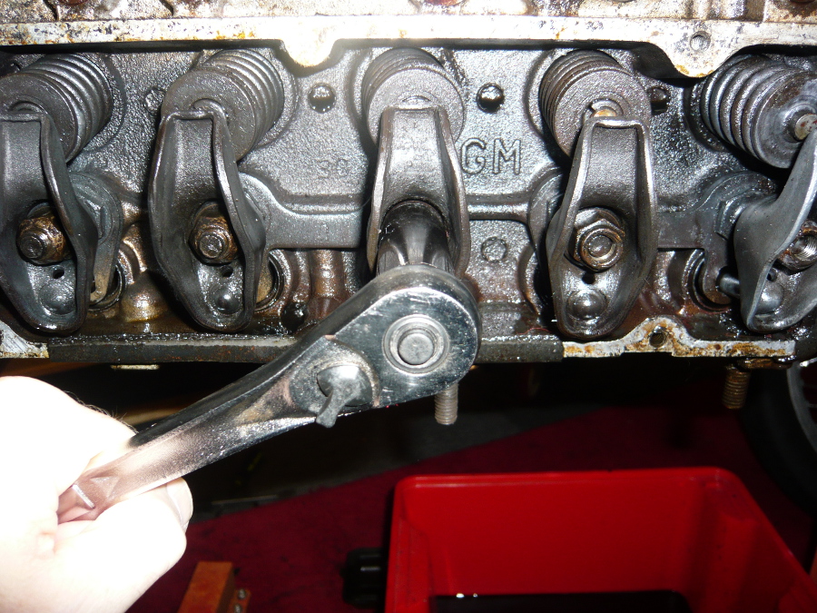
I ended up having to drill off the center top head nut and then use a cold chisel to split it. It's too tight in there to get a nut splitter. Underneath was one incorrect sized washer.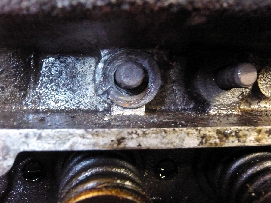
The pushrods are removed and marked for the sake of developing good organizational habits.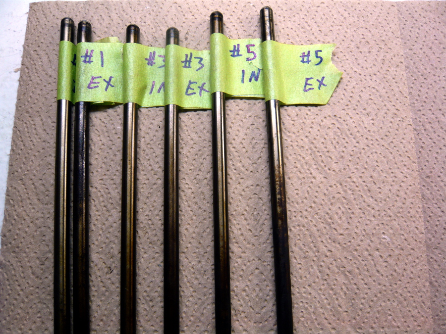
Then the pushrod tubes are pulled. If these are straight, I'll clean and paint them and use some new viton rings on reassembly. They're made of aluminum steel.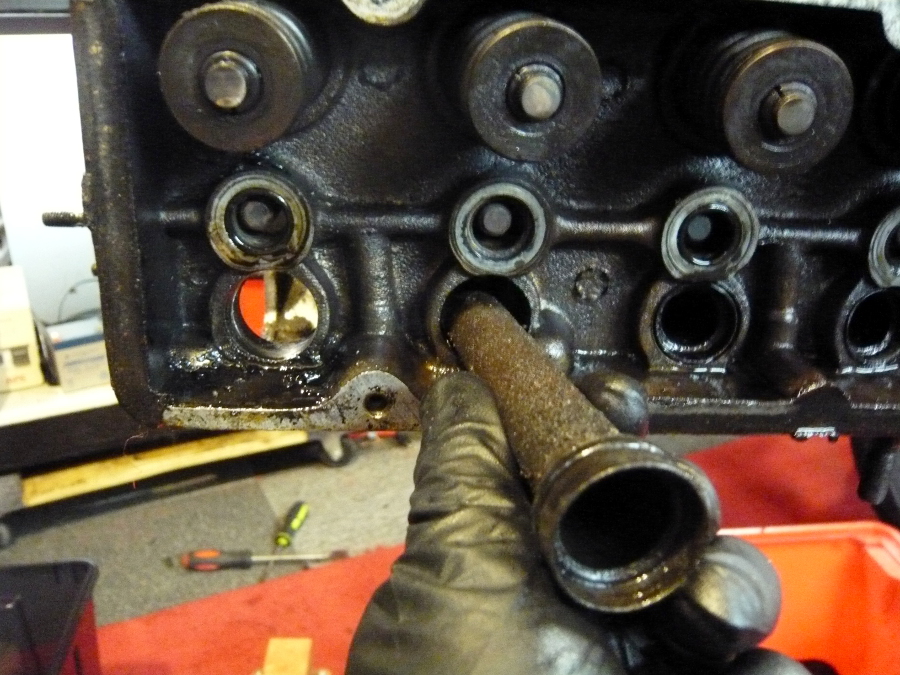
Posted by: r3dplanet Jul 10 2013, 02:03 PM
The head is free but before removal the carburetor mount studs need to be removed.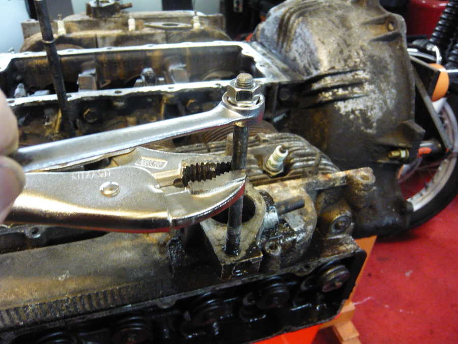
There are also nifty coil springs riveted to the bottom of the head. This pushes a small tube when heated upward to deactivate the choke on the carb. Not too different from the original heat pipe mechanism on my Chrysler 273 engine. Once removed the head can come off. A very slight tap with a mallet is all that was needed.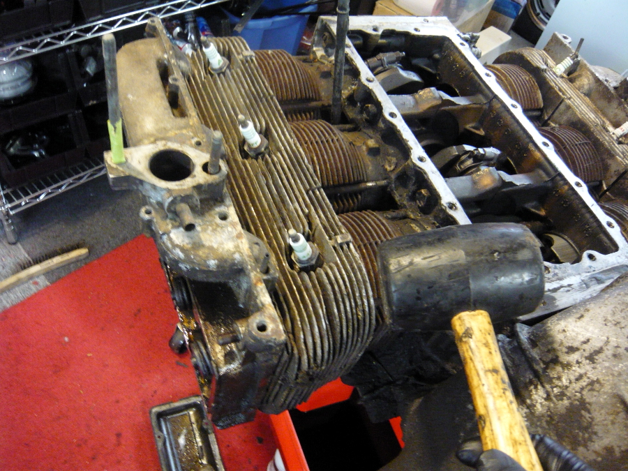
Off with her head!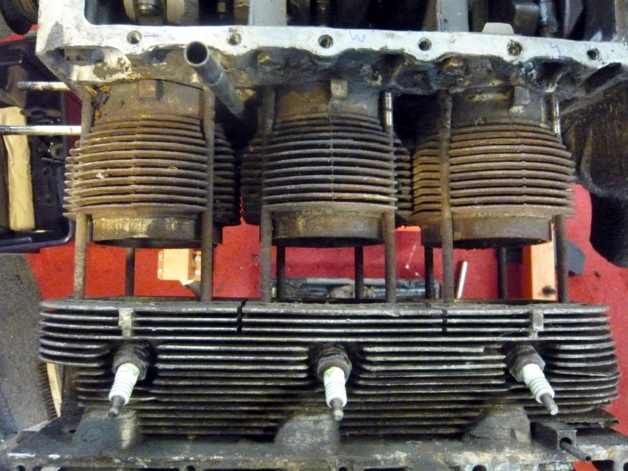
Yeah. She's had some wear. 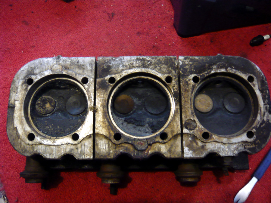
Cylinder #5 has quite a bit of bonus debris.  Doesn't matter. These cylinders and pistons are headed straight for scrap.
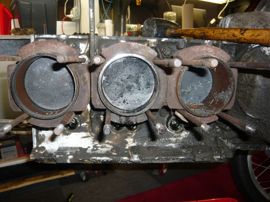
Now I need to remove the cylinders, pistons, and rods.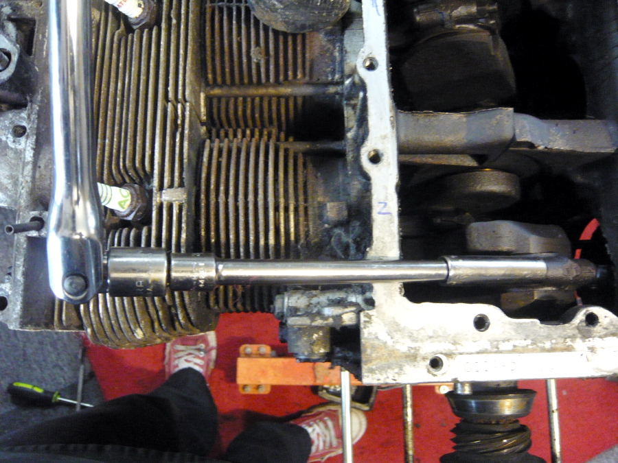
Posted by: aircooledtechguy Jul 10 2013, 02:44 PM

One particularly creepy evening, I found an ad on Craigslist advertising a warehouse full of Corvair parts including engines. So my pal Rory and I drove a hundred miles into the boonies late one rainy night to what turned out to be an unmarked, geographically isolated, former slaughterhouse illuminated by a single 60 watt light bulb. No cell phone reception, no escape. We were met by a couple of toothless brothers who couldn't stop talking about Daddy. Seemingly they only did what Daddy wanted them to do. Daddy wanted them to sell the stash of Corvair parts. Daddy wanted them to steal my Toyota cargo van. Daddy needed to approve the transaction of cash for an engine. Daddy, it turned out, was long dead. The two brothers kept trying to separate Rory and I, and the creepier of the two brothers kept demanding my car keys so he could test drive my van, despite my insistence that it wasn't for sale. For the first time in a long time, I wish I had a tazer gun on me. The brothers eventually showed us exactly what I wanted - an RD code 1965 110HP engine. Fearing for our lives, Rory and I muscled the engine into the van while the brothers went to find more stuff for Daddy to sell to us, or you know, maybe a club or some rope or a ball gag or something.
I left the $100 on the bench and tore the hell out. Rory and I laughed all the way back to town, ever so pleased that we were neither killed, nor raped, nor eaten. Plus, we were one up on a Corvair engine.
Damn!! I could hear the "dueling banjos" playin' in my head as I read that one!!
 I think you are very lucky to have got out of there in the same condition as you arrived. . .
I look forward to your build!!
Posted by: rick 918-S Jul 11 2013, 07:00 AM
Fun
Posted by: JRust Jul 11 2013, 08:02 AM
Oh man what have I done  .Excellent Marcus! @ Corvair powered 914's within an hour of each other will be great. You are sure tearing into yours quick. I'll be watching your build as I keep my eye's open for the pistons & cylinders for mine
Posted by: FourBlades Jul 11 2013, 09:06 PM
Cool, its the "Hills Have Horizontal Fans" build.
Now burn those gloves and wash your hands. Twice.
And check for tracking devices.
Good luck.
John
Posted by: sixnotfour Jul 11 2013, 11:06 PM
you guys should group buy 3 x 4 = 12 john barnes up in Seattle does corviar machine work..
Posted by: Randal Jul 12 2013, 09:00 AM
What do you use to clean up all the metal work?
How about soda blasting, but maybe that leaves residue that could cause engine problems.
Looks like a fun project.
Posted by: Dr Evil Jul 12 2013, 10:11 AM
 all you need for tins are the top and the two bottom ones under the cylinders. They rest needs to be fabbed, but this is actually easy. Cant wait to see this.
Why did you want the 110? The 140 comes with a nitrided crank. Roller rockers have been a nice touch on mine. I have a 4bbl to 6 port adapter if you want to do that 
Posted by: Dr Evil Jul 12 2013, 10:15 AM
Oh ya, I also have another 110 naked head if you want. Just pay shipping.
Posted by: Dr Evil Jul 12 2013, 10:15 AM
You can sell those P/C to Clarks for cores. Beats scrap price, maybe
Posted by: r3dplanet Jul 12 2013, 10:30 AM
Hi there.
When the project first started, I wasn't at all interested in power. Just a silent valve train and decent power. Many Corvair folks chimed in to tell me that the 140 motor was only faster at the very top end, and that the 110 was actually faster off the line. The 110 also had better mileage. Also, there's a cool EFI kit available here:
http://www.corvair-efi.com/Injection.htm
... and it only works on the 110 heads or lower. I still think that this EFI setup is the cat's pajamas. I'm not sure what I'll eventually settle on for a fuel system but I'm sure I'll get it figured out soon.
all you need for tins are the top and the two bottom ones under the cylinders. They rest needs to be fabbed, but this is actually easy. Cant wait to see this. Why did you want the 110? The 140 comes with a nitrided crank. Roller rockers have been a nice touch on mine. I have a 4bbl to 6 port adapter if you want to do that
Posted by: r3dplanet Jul 12 2013, 10:32 AM
That's good thinking. I won't be re-using the 110 heads I have now since I'm planning on buying a set of rebuilt 140 heads. But it's good to know that I can send them off to someone at Clark's who might make use of them.
Oh ya, I also have another 110 naked head if you want. Just pay shipping.
Posted by: r3dplanet Jul 12 2013, 10:35 AM
I usually just bring a carload of parts to Gary, my friend and super genius machinist. He hot-tanks everything for me. Short of that, there's also a metal dipper here in town and many blasters. For small parts I run everything through my ultrasonic cleaner with Simple Green and then coat everything with Boeshield. Finally, my plan is have all of the sheet and peripheral metal blasted and then powder coated. In fact, most of the parts I'm disassembling will not be re-used on the project. Mostly I just needed a good crank, crankcase, connecting rods, pushrods, pushrod tubes, hardware, attachment pieces, etc. All easy enough to have tanked or dipped.
-m.
What do you use to clean up all the metal work?
How about soda blasting, but maybe that leaves residue that could cause engine problems.
Looks like a fun project.
Posted by: r3dplanet Jul 12 2013, 10:31 PM
More disassembly.
Because the motor is a touch on the frozen side I couldn't remove the cylinders, rods, and pistons as a unit. Therefore the cylinders are coaxed off one at a time. Cylinders 1-3-5 are free.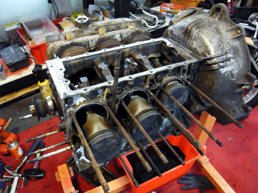
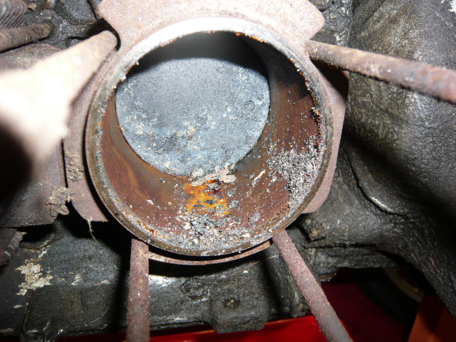
Now on the starboard side of the engine. I found that every one one of the top head stud nuts was frozen. It took two days of part-time work to torch each one repeatedly with MAP gas intermixed with drilling a 3/64" hole on either side of the nut and then splitting it with a sharp chisel. One can easily see that there's no nut where I'm torching. There was, but this is just for photographic clarity.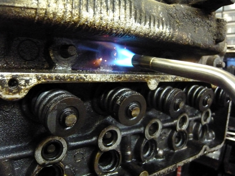
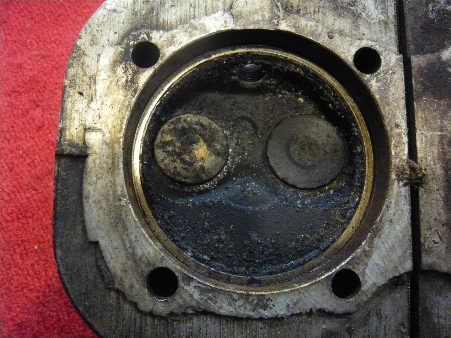
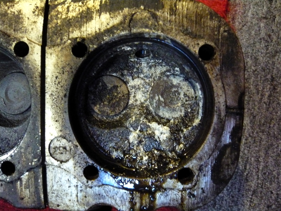
The starboard heads look even worse than the port heads. I have no clue what the hell happened on the outer two chambers to make them look so lousy.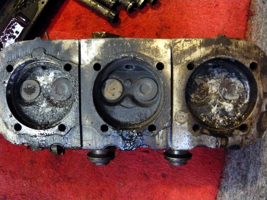
Even more debris on the #2 cylinder.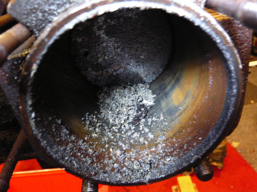
Finally free of the cylinders, the engine now spins quite nicely. 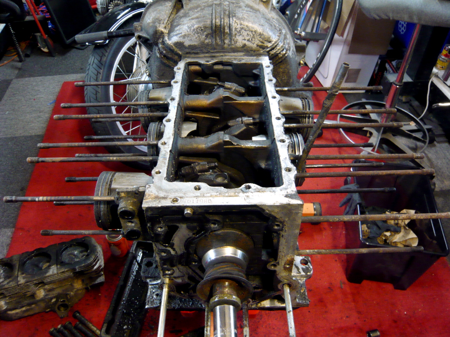
Now I can finally work out the connecting rod nuts. This actually took quite some time to remove. The bottom ones are hard to reach.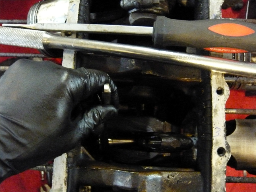
All clear.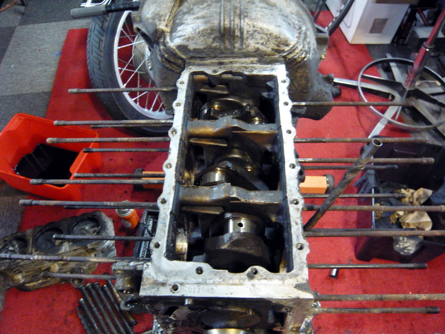
Posted by: r3dplanet Jul 12 2013, 10:46 PM
Flipping the engine shows 19 bolts to remove the oil pan. I'll discard this item also in favor a much better aftermarket aluminum unit with cooling fins.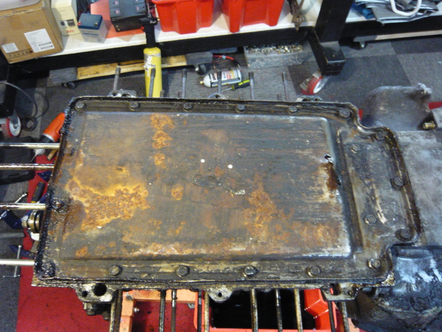
And the oil pickup is revealed.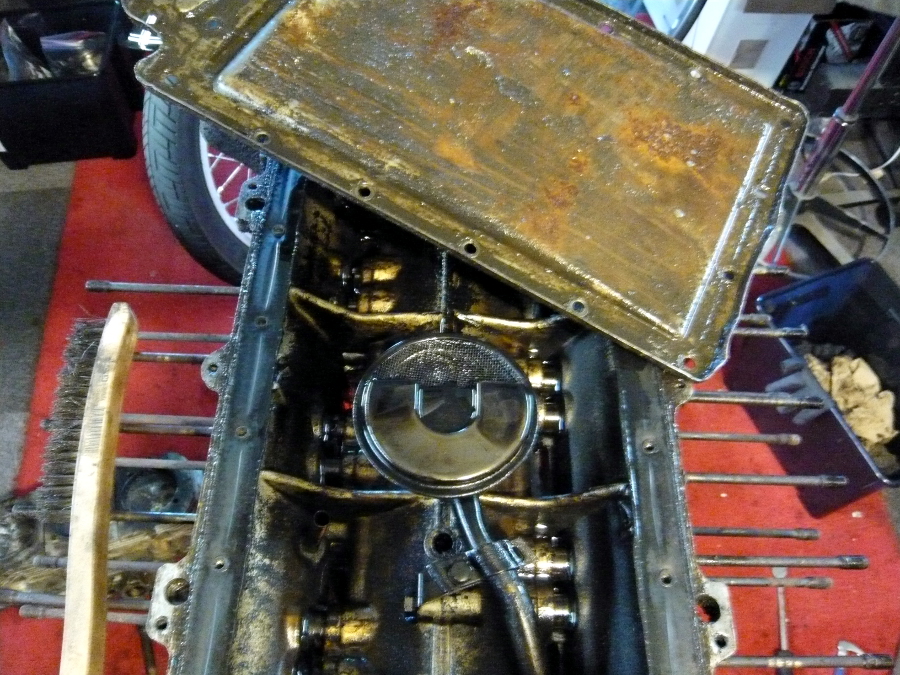
By CAREFULLY tapping the bottom of the dipstick tube with a 16oz hammer the case is free of one more accessory.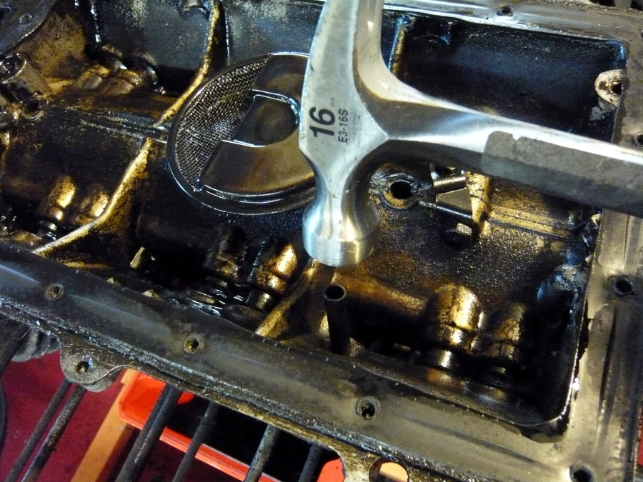
The oil pickup tube was really stuck. But I found that I could use a long extension and a 10mm socket to carefully drive it through the case from the outside. GM made a special tool for this job but it's completely unavailable.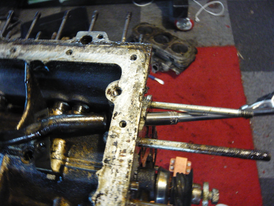
This part I've been dreading. The clutch, pressure plate, and flywheel assembly were just on the wrong side of the engine stand, and all of the bolts were super rusty. After a two day soak with Kroil, I was able to slowly draw them out.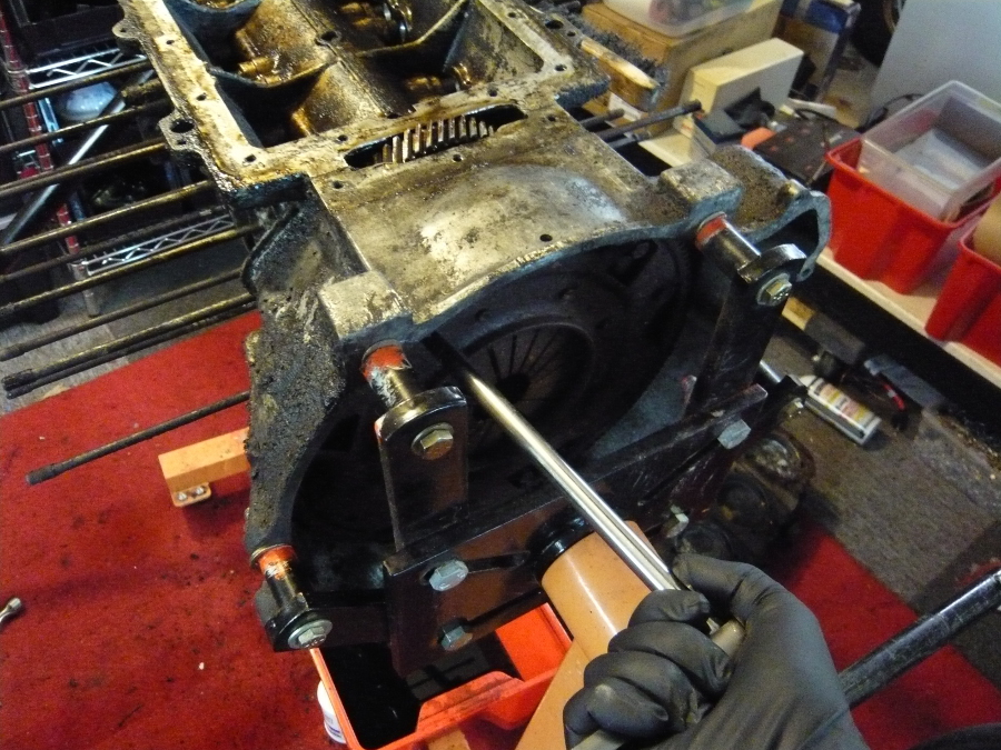
The clutch plate and clutch disc are free. I unbolted the bottom bolts on the engine stand and was able to drop them right out.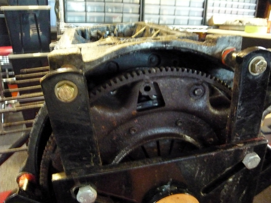
And finally the flywheel is revealed. The six flywheel-to-crank bolts looked as rusty as my high school German language skills.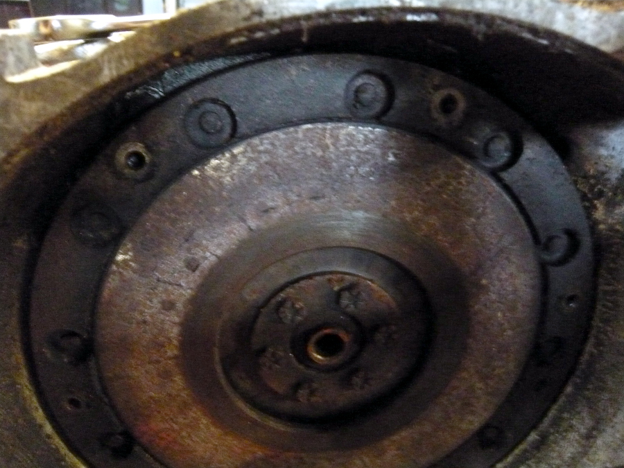
I couldn't keep the rotating assembly from spinning when I tried to loosen the bolts. So I threaded one bolt into the flywheel thread and another to the case and wedged a 1/2" combination wrench in between them. With even, heavy pressure on my long socket wrench the bolts slurped right out.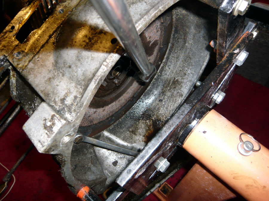
Finally just the bell housing bolts remain, but I need to prop up the crank case first. That's a job for this coming weekend. The bell housing, clutch assembly, and flywheel will also be discarded since it won't be used in the 914.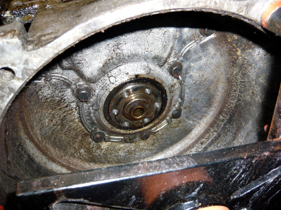
Posted by: Dr Evil Jul 13 2013, 12:23 AM
Your heads show that water and oil were allowed to accumulate in there.....common with poor storage practices 
Posted by: r3dplanet Jul 13 2013, 01:16 AM
Yeah, it was pretty damp in the slaughterhouse.
Your heads show that water and oil were allowed to accumulate in there.....common with poor storage practices
Posted by: relentless Jul 13 2013, 01:51 PM
Ah, this brings back memories. My buddy had ran my 1.7L up to around 70mh in third passing a car, and caught second gear instead of fourth. So I was looking for a "new" and more powerful motor. Back in 1980 I started with a $250 140 Corvair engine and by the time I was done I had over $3k invested. Back then, I could have had a decent Porsche six for that price. 
You mentioned something about a stock 2.7L going to 3.1L, but as I recall the stock Corvair was 2.4L and I went .030 over on pistons to get about 2.7L. I was assisted in the engine build by "Terry to the Nth" who made me do everything perfect - or else! He even CC'd each head so we'd know exactly what the C/R was - to the drop! Keith Corp in Ashland balanced all the reciprocating parts and the engine sure was smooth. He said it would be good for 8,000 rpm.
The main problem I had with the reverse rotation engine was having the fan belt pop off a few times. Kind of a dizzy design, the belt going from horizontal to vertical and back. I tried mounting a spring from the idler pulley to the firewall but the racket from the spring was horrendous. I think I went to a slightly longer fan belt to solve the problem.
So welcome to the world of Porvairs, where we spend lots of dollars to make our cars worth-less (not worthless).
Oh yeah, I just remembered that Terry made me take the block down to the airport and have it zyglowed. They use a special dye to check the aluminum block for cracks.
Posted by: Dr Evil Jul 13 2013, 09:03 PM
Why would you put a spring on the tensioner when it is held in place by bolts??? It is not dynamically adjustable.
fan belts pop off when they are on too tight. I have not had one come off, yet. I know many vair owners that have not popped belts once adjusted looser.
The engines are 2.7 from 65 on. Earlier than that they had different sizes which I dont know.
Posted by: rick_cv Jul 14 2013, 09:55 PM
Just curious. What do you use for flywheel, clutch and pressure plate? I have seen a few 215mm flywheels for vw/corvair conversions but the seem to be rare and expensive.
Posted by: r3dplanet Jul 14 2013, 10:28 PM
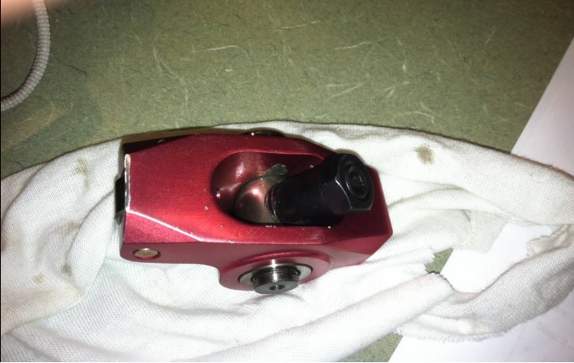
Good question. The flywheel is a custom part that's been produced by many manufacturers for decades. Crown, KEP, Otto, and others have made them. It's essentially a 130 tooth solid flywheel that has a built-in pressure plate. See photo #1 of this thread. The actual clutch disc and clutch are stock VW/Porsche parts and you can use any item you want. The 130 tooth flywheel is basically where the transition happens. The flywheel bolts to the crankshaft, and then the tooth arrangement allows for use of the stock starter. If you just swap the pinion gear in the gearbox, you would then have to use a reverse rotation VW starter or a stock Corvair starter with a small adapter. Somewhere I have the rest of the clutch pieces. When I find them I'll post pics.
Also, someone else asked about displacements on the engines. The very earliest 1960 Corvair engines were 140cid, but after 1961 a 145cid engine was made an option. With 1964 models (the great transition year) all displacements went to 164cid (2.7 liters).
-m.
Posted by: Dr Evil Jul 15 2013, 10:32 AM
I got a set off of ebay; Crown adapter from engine to VW gearbox and flywheel. They are packed up for a future project. It was not that expensive, all things considered.
Posted by: rick_cv Jul 15 2013, 02:55 PM
I see 127 tooth, 130 tooth and 215mm flywheels. I take it the one to use is the 130 tooth. Do you use a bug pressure plate/clutch, bus or 914? Or a special pressure plate/clutch for the conversion. Thanks for the replies fellas. I thought JRusts new project was pretty neat also and will probably never have the money to do a Porsche six conversion. Just following my curiosity.
Posted by: r3dplanet Jul 15 2013, 05:17 PM
You certainly want the 130 tooth flywheel. I genuinely don't know if the clutch and pressure plate is straight VW or 914 specific. But since I want to clean up the assembly I have, I'll take it apart, get some photos, and glean any part numbers. All I can see right now is that I have an F&S pressure plate.
I see 127 tooth, 130 tooth and 215mm flywheels. I take it the one to use is the 130 tooth. Do you use a bug pressure plate/clutch, bus or 914? Or a special pressure plate/clutch for the conversion. Thanks for the replies fellas. I thought JRusts new project was pretty neat also and will probably never have the money to do a Porsche six conversion. Just following my curiosity.
Posted by: r3dplanet Jul 15 2013, 11:27 PM
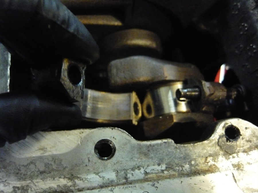
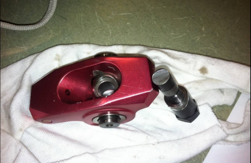
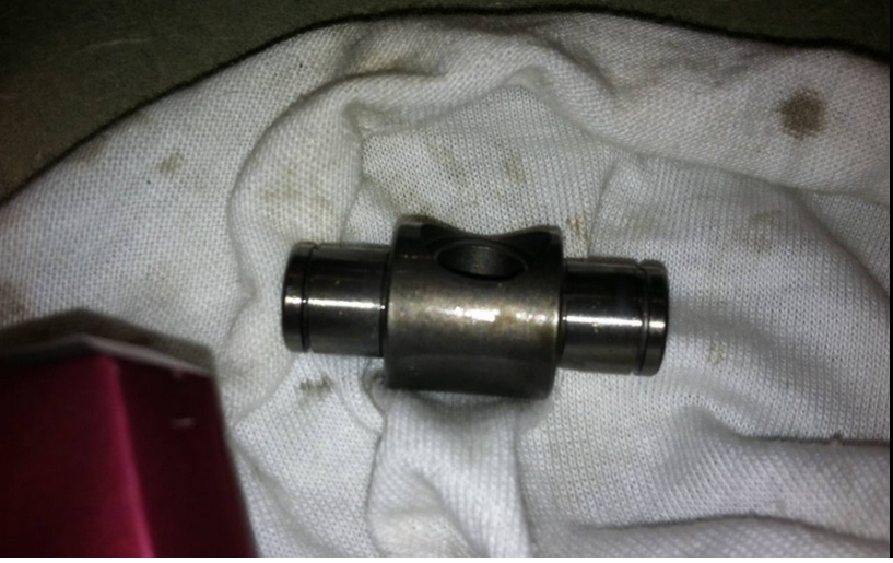
Okay, I have to admit that I'm a little confused but I'm sure that this challenge will be met and solved. To solve the curiosity for rick_cv, myself, and perhaps others I disassembled my crusty part.
The flywheel assembly is a sandwich made of the clutch disc, flywheel, and pressure plate. The pressure plate is bolted right to the conversion flywheel with the clutch disc kept inside. Here's a closer pic. I know these parts are rusty, but they'll be cleaned and balanced before being put into service.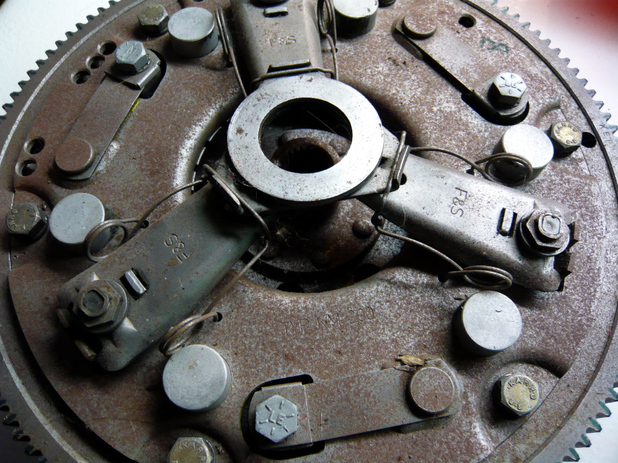
Apparently, this flywheel assembly is from Kennedy.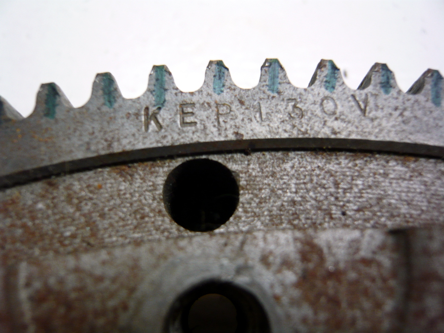
The clutch disc is also F&S (which is just Sachs now, isn't it?) and measured 180mm, quite a bit smaller than the 215mm 914 clutch. Hopefully that won't be a hideous issue. But the 180mm size tells me that this is a standard VW part - not a 914 part. Clark's sells three clutch discs. A standard VW clutch, and high performance clutch, and a racing / high hp clutch. I'll probably replace this clutch disc for one of the racing ones.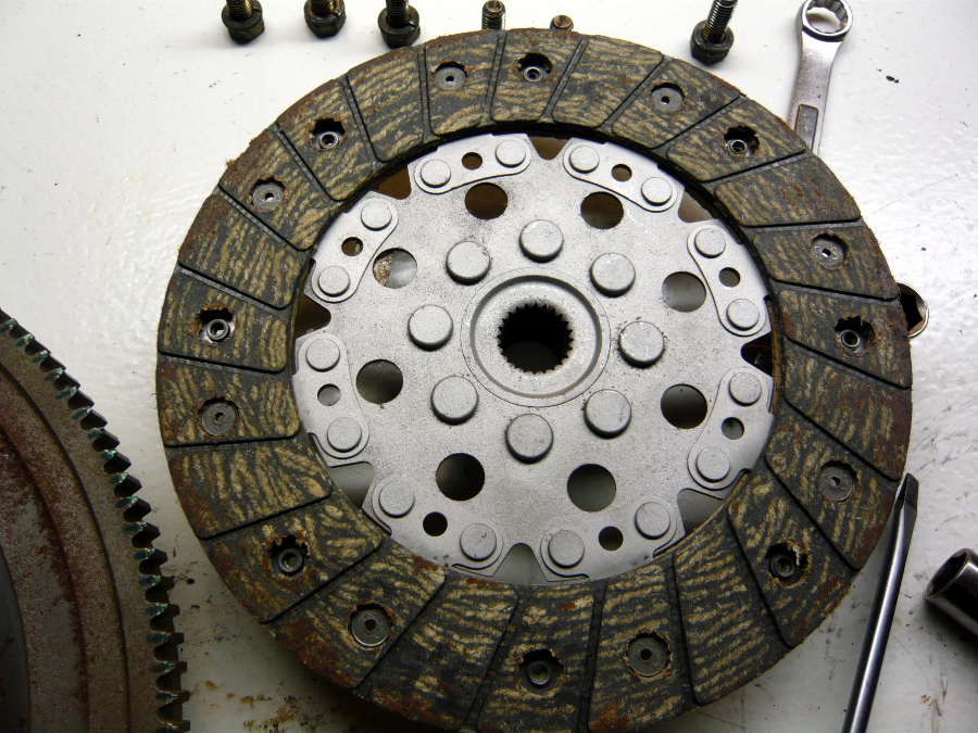
Finally, here's a pic the recesses for the flywheel bolts.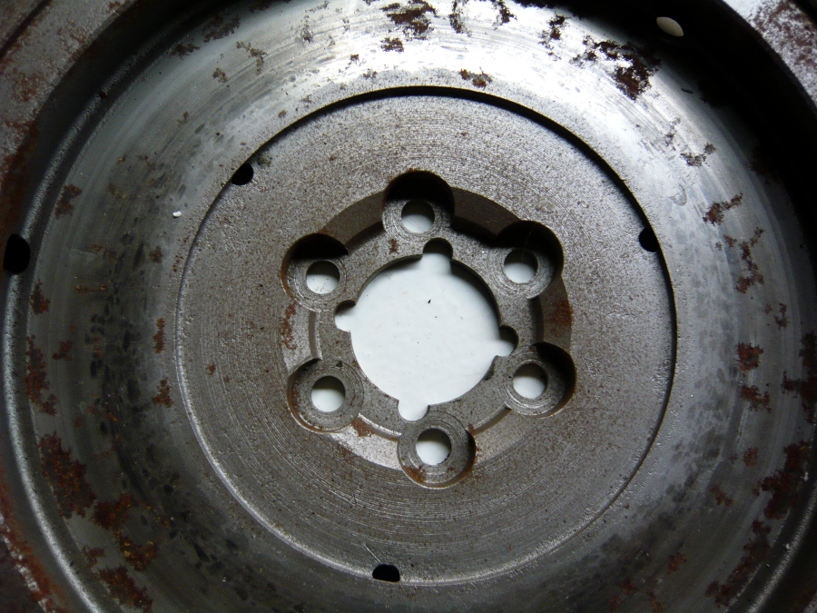
Posted by: Dr Evil Jul 16 2013, 07:25 AM
That is a bus pressure plate. Possible a bus flywheel and disk that has been converted as well.
Posted by: Dr Evil Jul 16 2013, 07:27 AM
Here is Clarks catalog for the conversion flywheels.
http://www.corvair.com/user-cgi/catalog.cgi?function=goto&catalog=SPECIALTY§ion=OTTO&page=OTTO-39
Posted by: rick_cv Jul 16 2013, 01:45 PM
That is what I thought when I first saw your image- that's a bug pressure plate. Don't know if it works with a 901 trans though. Will be watching this thread to see how it comes together.
Some good tidbits-
http://www.tunacan.net/t4/tech/flywheel.htm
Posted by: r3dplanet Jul 16 2013, 10:57 PM
From what I've read the adapter plates should fit any VW or 901 gearbox of the period. But I'll cross that bridge when I come to it. We're sort of getting ahead of where I want to be, so this issue will be revisited when the time comes.
That is what I thought when I first saw your image- that's a bug pressure plate. Don't know if it works with a 901 trans though. Will be watching this thread to see how it comes together.
Some good tidbits-
http://www.tunacan.net/t4/tech/flywheel.htm
Posted by: r3dplanet Jul 17 2013, 12:22 AM
I've taken the past couple of evenings to do some cleanup and hit the reset button on my work area. I douched the tools with WD-40, cleaned the parts I've removed with my ultrasonic cleaner and then coated them with Boeshield, and finally bagged and tagged them. There are a large number of parts that won't be re-used for this application: flywheel, pressure plate, valve covers, bell housing, heads, cylinders, etc. It feels weird tossing that stuff aside. From an existential point of view it's really thought provoking to think that at this moment the engine does not actually exist. Instead, it's just several bins holding a bunch of constituent parts in a garage explosion. Leaving and returning. Chaos and Cosmos. Big Bangs and Brahma years. Hey, I was an academic for a long time so this is where my brain goes when I'm in the shop. Inner space. Besides, Carl Sagan is my spirit animal.
So here's the detail on the final stages of disassembly. After removing the engine from the stand and setting aside the bell housing, this lovely creature now graces my workbench. One might wonder why it looks like a robotic pin cushion. This is because the head studs are not to be removed from the case unless it's absolutely necessary. There's a test to torque them down to 30 or 40 lbs (depending on which manual you read) and see if they hold their torque. If they do, then it's smooth sailing. If not, then it's time for creative machining.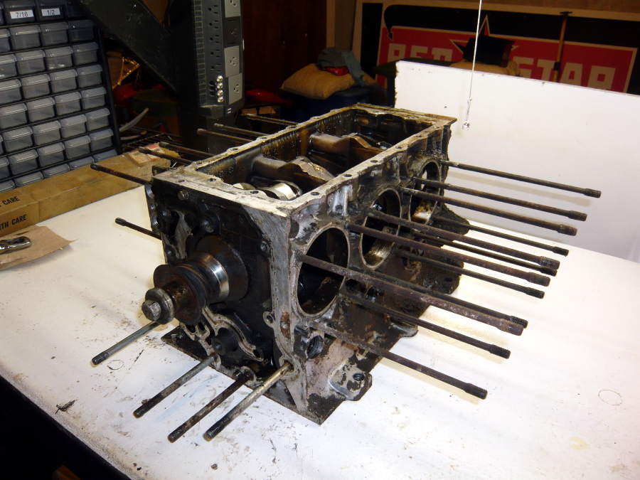
Here's a front view for no reason.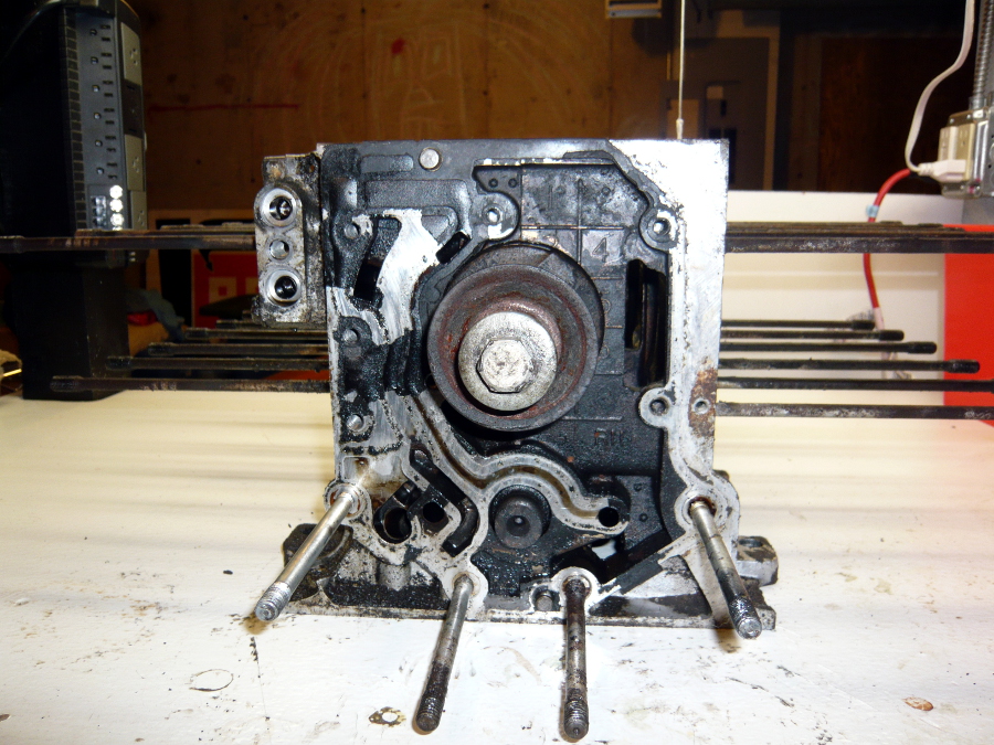
This part is the oil cooler adapter. I could have taken it off at any point during the disassembly, but both the 1965 Corvair Chassis Shop Manual and Bob Helt's The Classic Corvair say to leave this connected until this point. By the way, these manuals are fabulous. For dolts like myself they're really a fantastic resource. If you do a Corvair conversion yourself, be absolutely sure to get them. They're both in print.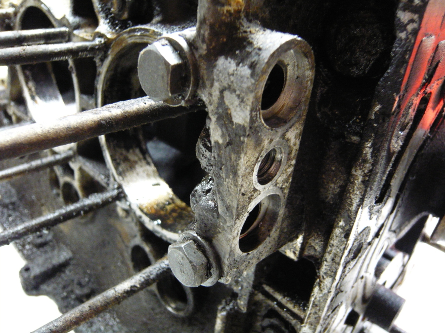
And .. removed.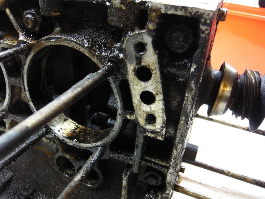
Now it's time to split the case. Here's a side view clearly showing the eight through-studs and corresponding nuts that hold the hemispheres together. Four on top, four sort of in the middle. Just before removing them I made sure to remove the bottom bolt that holds the oil pickup to the case.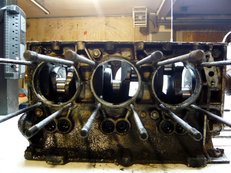
Having the motor on the bench sure makes this part straightforward. Using a ratchet and a long socket wrench, each comes off in turn with a little effort. No crazy stuck nuts like the ones holding the head.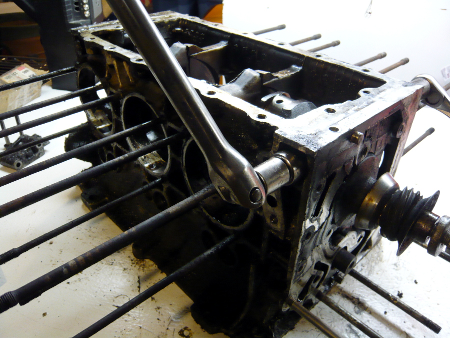
Now the big moment. A slight tap with a rubber mallet along the top edge of the inside of the case and it just pops apart. It took very little effort. 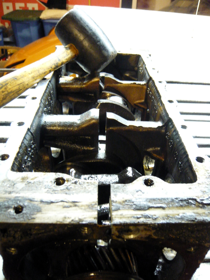
In fact, it popped apart a little too readily. The manual says to prop the bottom of one half of the case with a 2x4 to push one side of the engine higher than the other. That way you lift the free half and leave the crank and cam in place on the other side. This is to prevent the crank and cam from just spilling out onto the floor. Just as I reached for the wood, it split right open. Whoops.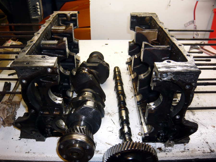
Yeach. This crank bearing is scored all to hell. The opposite side is also. The rest of them look like they have normal wear.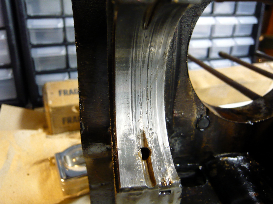
Posted by: r3dplanet Jul 17 2013, 12:42 AM
Moving along with a close-up of cam wear. This doesn't matter as the cam and cam gear will be replaced.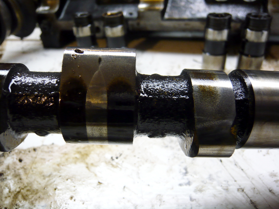
A glamor shot of the starboard half of the engine with the hydraulic lifters and crank bearings removed, which I'll catalog and keep for reference. Note that the Corvair engine does not use cam bearings. Instead, the cam rides only on the oil between the cam and the engine case. I might have the cam surfaces coated with Teflon before re-assembly, assuming this case checks out. Before getting that far I'll get the case hot tanked and checked for cracks with Zyglo (thanks, Relentless!). That's coming up next.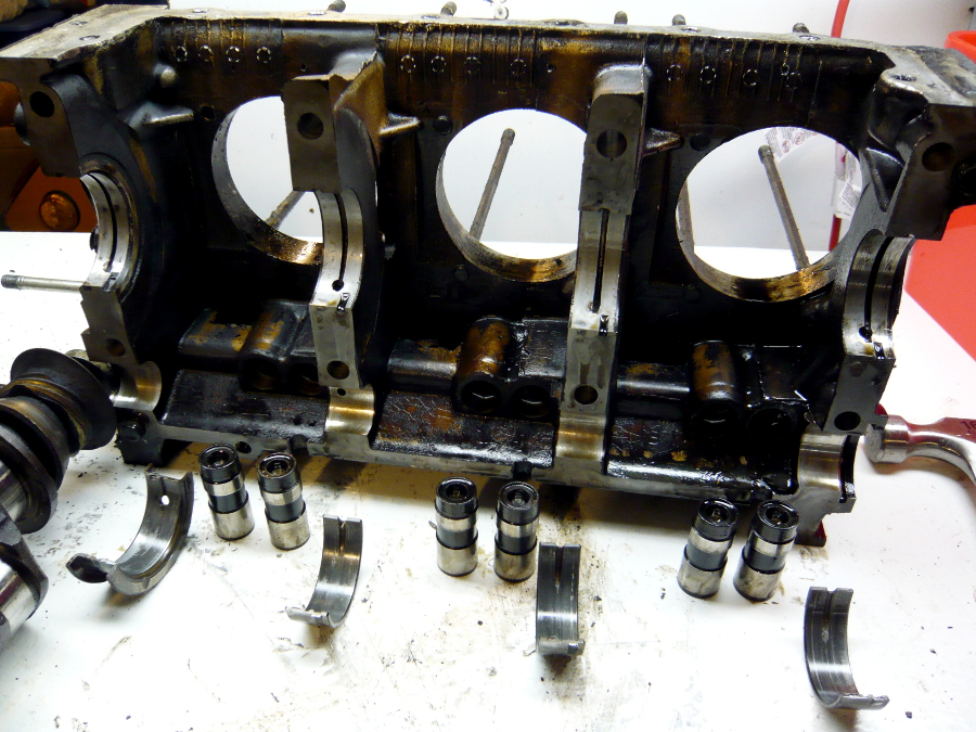
The corresponding glamor shot of the port side of the engine. This is the end of disassembly. Next up: finding a suitcase full of money to get the rebuild parts and checking and prepping the parts I already have.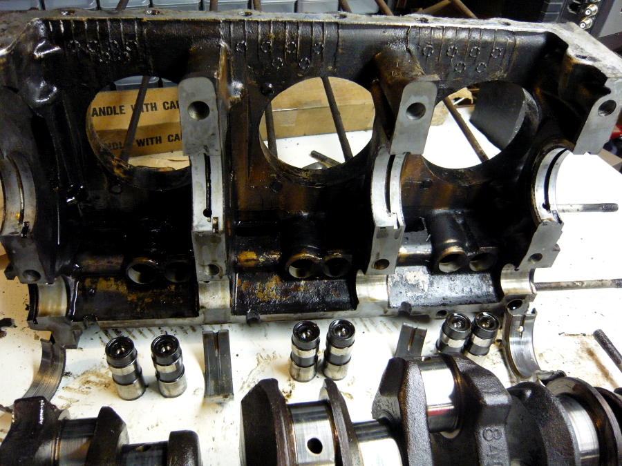
Posted by: relentless Jul 17 2013, 12:36 PM
You're making good progress Marcus. It's been 33 years since I built my Corvair engine, but bits and pieces of the process keep coming back.
As I recall Terry (to the n'th) didn't want me to go more than .030 over on the barrels because he was concerned about the thinner metal being less able to dissipate heat and also he had me get forged pistons, and I believe Moly coated rings (?). Seems like there was a specific cross hatching on the cylinders also. Every time I'd go wild and suggest something like boring the cyls out to .060 he'd look at me and say "do you want an engine that lasts ten thousand miles or one that will last longer?"
I'll be interested in seeing what advances they have made in the last three decades and what parts you select for your build.
Posted by: Dr Evil Jul 18 2013, 07:04 PM
No special cross hatch, no special rings, and you can bore out farther if you open the registers which is required when using the TI VW cylinders. Please do not put forth partial memories as gospel unless you have some backup for them as this can cause damage to peoples engines and wallets in the future.
Posted by: r3dplanet Jul 18 2013, 09:22 PM
Not much happening today. I spent a good hour hashing things out with my mechanic. I also hoping to get the ball rolling with American-pi about specialty machine work for the roller rockers and 3.1 conversion. I also started a thread over at corvaircenter.com asking about engine specifics. It's lively and informative. And comes complete with a troll.
http://corvaircenter.com/phorum/read.php?1,633330
Today I cleaned the crap out of the pushrod tubes, but I still plan to soda blast them and powder coat them.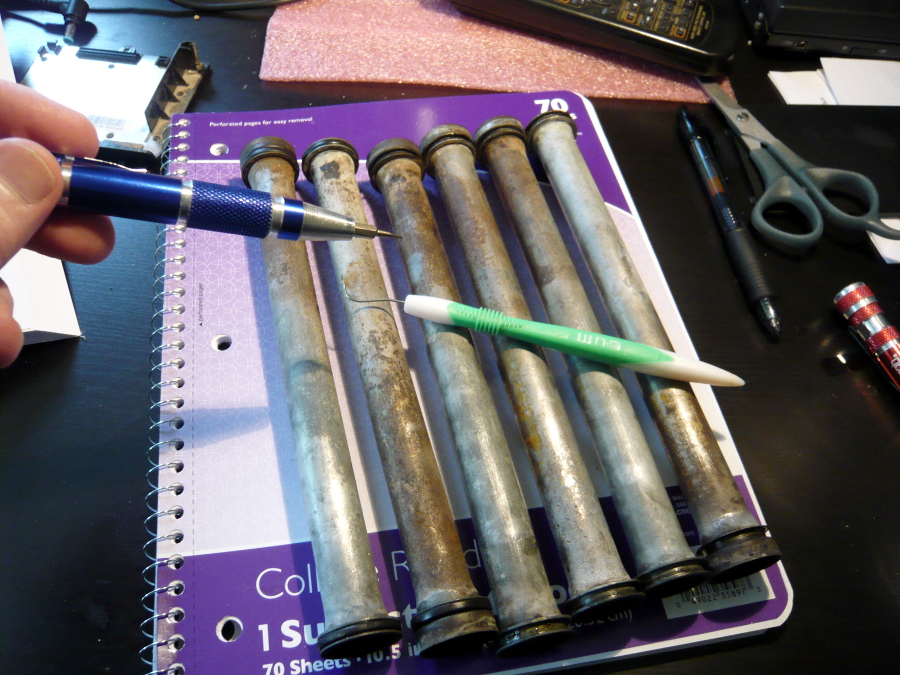
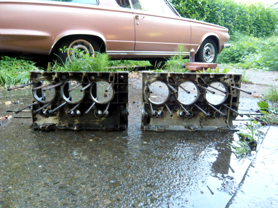
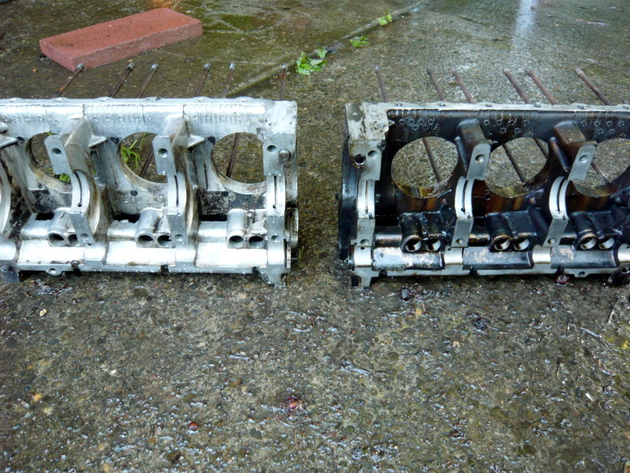
It was super nice out this evening so I pulled out the Easy-Off and the power sprayer and hosed down the engine cases. They're going to the machine shop tomorrow. Here's the before and after shots. Remember, this is just a once-over to make it easier for the machine shop.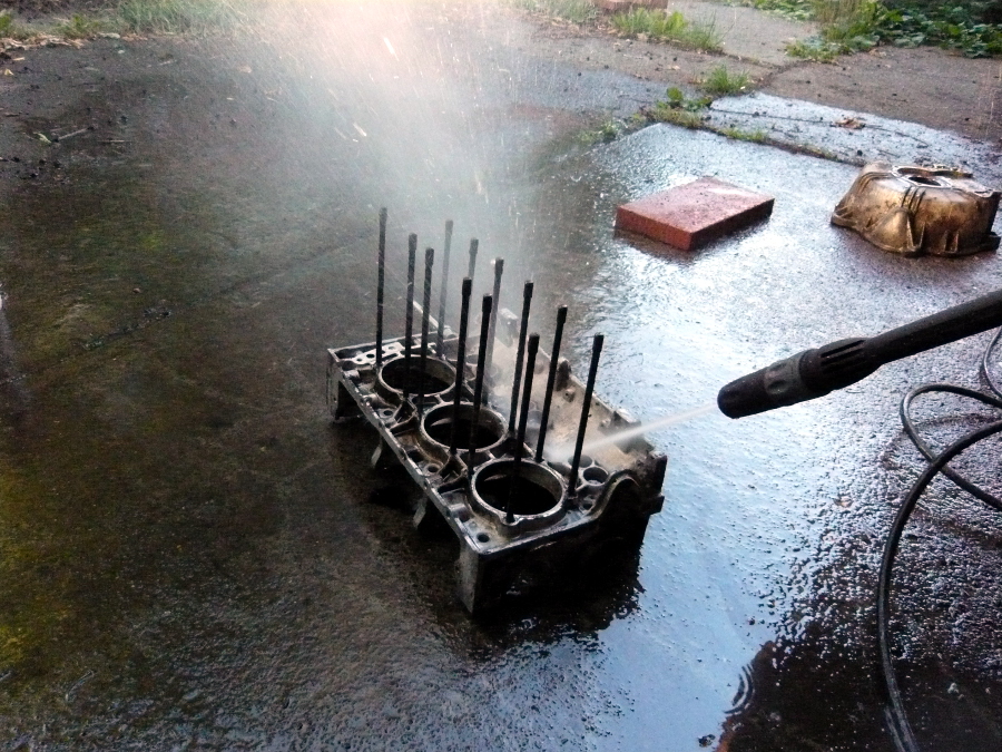
Posted by: rick_cv Jul 19 2013, 02:46 PM
Who are you using for a machine shop? Dan Hall's still open?
Posted by: relentless Jul 19 2013, 03:01 PM
Well Marcus, Dr. Evil says I shouldn't comment or offer advice as gospel, even when I put a (?) question mark after what I recall we did when building my engine, and mention it's been over three decades since the work was done. So if you want me to no longer comment or make suggestions I will gladly abide by your decision. I make no representation as to my experience being "gospel."
Maybe you would at least let me post a picture out here how the idler pulley can be *spring mounted* since D. Evil said it couldn't be done!  I found it interesting that someone else also had problems with the reverse rotation belt pulley; something Terry said was probably due to the factory designing the engine to track the belt under load in the original direction.
Posted by: Dr Evil Jul 19 2013, 03:02 PM
Last I saw Ray Sedman (sp) was doing the 3.1 with good street credit, but not cheap. There are a few that do the service, but search the web for references. I had mine done in Harrisburg by a very competent shop that does anything, so it is possible to have a local do it if they are smart
Posted by: Dr Evil Jul 19 2013, 03:39 PM
Well Marcus, Dr. Evil says I shouldn't comment or offer advice as gospel, even when I put a (?) question mark after what I recall we did when building my engine, and mention it's been over three decades since the work was done. So if you want me to no longer comment or make suggestions I will gladly abide by your decision. I make no representation as to my experience being "gospel."
Maybe you would at least let me post a picture out here how the idler pulley can be *spring mounted* since D. Evil said it couldn't be done!
I found it interesting that someone else also had problems with the reverse rotation belt pulley; something Terry said was probably due to the factory designing the engine to track the belt under load in the original direction.Please do post a pic. I didnt say it couldnt be done, I asked why. The original design does not necessitate a spring and make no provision for one.
As for offering your recollections on corvair engines, you only put one (?) in one of your posts, but you have posted plenty of incorrect info. My only aim is to keep info factual and accurate, not to belittle. I do not want you to leave, just check your facts. All the stuff you are posting about may apply to early vair, but not the late model, 2.7, 110 or 140hp blocks. Having built up one far more recently than 3o years ago, and modifying it as Marcus desires plus some, and researching them, it get tiring when I have to post corrections to misinformation posted in here. The vair may have the most misunderstood of all engines with lots of BS out there. See the comment about "rubber main bearings". Yes, there was a person that both posted that they used rubber main bearings AND believed it about 10 years ago when I first started into vair engines.
Marcus, there is a guy in Santee, CA named Star Cooke who knows these engines really well. He costs money and is arrogant, but if you want something done right he is an option. I have a set of his heads converted for weber 3A carbs.
Posted by: r3dplanet Jul 19 2013, 04:04 PM
I want to tell everyone that this is my favorite automotive forum. We keep it technical and rarely do threads devolve into shouting matches. That's pretty much the norm for the classic Chrysler forums I belong to. I don't even post there anymore. Even my thread over at corvair central was accosted within minutes by a single assclown. One of the things I love about 914world (and BMWMOA) is how we manage to keep it clean, providing a sandbox for whomever to sling whatever. Compared to other forums I belong this, this place is an oasis. For example, when conversions are brought up nobody starts a flamewar about who's the idiot. Any conversion - Wankel, Subaru, SBC, etc., is going to be in some minor way controversial. For my own, I think it's low stakes. One day I'll build up a race car and throw the Corvair engine into it. Short story long, I welcome both past and current experiences with those who are Corvair knowledgeable (Relentless) as well as peer review (Dr. Evil). That is the path to factual knowledge. Ultimately the 914 attracts a certain crowd, and they are efficiency-loving gearheads with panache and good attitudes. So, hooray for us.
So far I found a few surprising items in this adventure: Corvair forum "experts" bicker a great deal. There has been so much time and so much development over the years that trying to find the one right way to accomplish any specific task is immediately grounds for argument. Sorting out what's right for me has taken far more time than I had expected. For example, with rockers. There are a myriad of ways to do this and it doesn't help that GM doesn't make them anymore. So there are dozen solutions for replacement, each of which has it's own believers who think the others are stupid. I mean, seriously, rockers.
Another surprising item is there are very, very few washers as far as fasteners go. I'm used to finding lock washers everywhere I look. On this engine I've found only a few. The nuts all seem to be nuts + flange to make a ... nutwasher.
As far as machine work goes: the case prep, crank regrind/polish, balancing of rods, flywheel, etc., is all done by my friend and machinist Gary who's a super genius.
For the specialty stuff like the head, rod, and case work for the 3.1 conversion is (hopefully) going to be done by American-pi. Their work appears stellar and I think the most economical way to go.
Dr. Evil, you hit the nail about Star Cooke. I'm buying my 140 heads from him. Expensive, but absolutely rebuilt correctly by a guy with an excellent reputation and spends his days doing this exact work. It's worth the money for the piece of mind.
Posted by: Dr Evil Jul 19 2013, 04:26 PM
I can not seem to stick around on other forums. This one takes what little time and attention I have and I like it and the people so much. I have met probably 1000 of the members her all over the country and in Canada (they count, too). You have a great attitude, Marcus.
The one thing that I found good fighting over was how to bore the case. Sedman has the "actual blueprints" and bores the case where the registers where supposed to be, not based on where they are. I did not bother with this and just had them bored. My fuel systems have been the only problems as I continue to experiment.
Have you seen Mark Langford's aircraft page with his 3.1 conversion? Lots of great info there. Also, there are good threads here with links.
Posted by: andys Jul 19 2013, 04:29 PM
I think it was one of the HP book series on "How to Hot Rod the Corvair" that I bought when we ran SCTA (dry lakes) out at El Mirage in the late 60's (ran a 180 Corsa in F/Supercharged). Wife recently complained about my library (catch-all) so durring my clean up, I think I threw it out. I hung on to that book for 40+ years.
Andys
Posted by: JRust Jul 19 2013, 06:27 PM
As far as machine work goes: the case prep, crank regrind/polish, balancing of rods, flywheel, etc., is all done by my friend and machinist Gary who's a super genius.
For the specialty stuff like the head, rod, and case work for the 3.1 conversion is (hopefully) going to be done by American-pi. Their work appears stellar and I think the most economical way to go.
Dr. Evil, you hit the nail about Star Cooke. I'm buying my 140 heads from him. Expensive, but absolutely rebuilt correctly by a guy with an excellent reputation and spends his days doing this exact work. It's worth the money for the piece of mind.
Man I need to pick up another motor. Maybe I can do my stuff at the same time & we can get a discount
Much easier on a machine shop to do 2 of the same right?
Posted by: r3dplanet Jul 19 2013, 06:54 PM
Wait, what? What's wrong with your motor?
I know a couple of banjo-playing brothers with a domineering dead father who could probably make you a deal. Just bring a pistol, give GPS directions to your loved ones, and bring some friends. Or it will be more like Kalifornia than Deliverance.
You bring up a point that I should probably have made earlier. I know that my project won't be inexpensive. But luckily the nature of the work is that I can pay as I go. I like that. I think that a properly stock 140 with good head work would be more than enough power for the 914. I'm going a little nuts with my engine (a) because I want to see where this goes and (b) I'm secretly trying to show that even with all of the big modifications this motor will get, it can still be done for about 1/3 of the cost of the Porsche six. I think the -6 is the coolest motor (except that POLO motor). But absurdly expensive. I'm showing an alternative. I also have a sneaking suspicion that for what I spent on my motor, it will be about the same as a souped up Type-4. Last, for what I'm spending on the monster 3.1 liter, I could have spent less than half and built up a stock 140. That's where the smart money is.
So - yes! Maybe we can double up on some machine work. We also need to develop a nice cradle for the engine.
I've already learned that if I were doing this again I wouldn't even bother with a donor motor. At the end of the day I'm only using the major pieces from the donor, and I'm sure I could have found cleaned and prepped bits for about what I spent ($100) on the motor.
As of today, here's the bucket of reusable parts: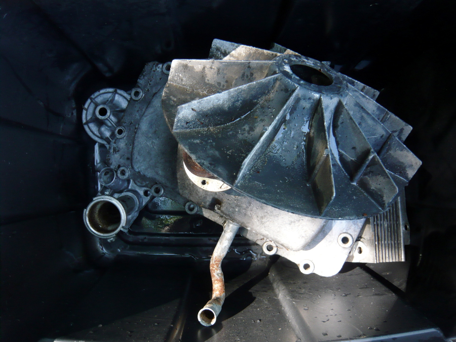
Aside from the engine case and crankshaft, this bin includes the top cover, front cover, oil filter assembly, fan (and bearing), and pushrod tubes. Everything else is scrap.
As far as machine work goes: the case prep, crank regrind/polish, balancing of rods, flywheel, etc., is all done by my friend and machinist Gary who's a super genius.
For the specialty stuff like the head, rod, and case work for the 3.1 conversion is (hopefully) going to be done by American-pi. Their work appears stellar and I think the most economical way to go.
Dr. Evil, you hit the nail about Star Cooke. I'm buying my 140 heads from him. Expensive, but absolutely rebuilt correctly by a guy with an excellent reputation and spends his days doing this exact work. It's worth the money for the piece of mind.
Man I need to pick up another motor. Maybe I can do my stuff at the same time & we can get a discount
Much easier on a machine shop to do 2 of the same right?Posted by: r3dplanet Jul 19 2013, 06:55 PM
Ah, I found an out-of-print copy and it's on the way. Good catch!
I think it was one of the HP book series on "How to Hot Rod the Corvair" that I bought when we ran SCTA (dry lakes) out at El Mirage in the late 60's (ran a 180 Corsa in F/Supercharged). Wife recently complained about my library (catch-all) so durring my clean up, I think I threw it out. I hung on to that book for 40+ years.
Andys
Posted by: r3dplanet Aug 8 2013, 08:23 PM
Some minor progress happening today. The machinist cleaned and bead-blasted all of the aluminum and magnesium parts and they look super.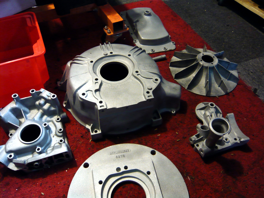
He ran the case halves through the parts washer but we opted not to bead blast the case hemispheres until we know for certain that the case tests out okay. He inspected for cracks and deformations and none were found. So I cleaned and very lightly polished the cam and crank journals to get some clean readings. I'm also having the old cylinders cleaned up so I can run a head stud torque test and then sell them off.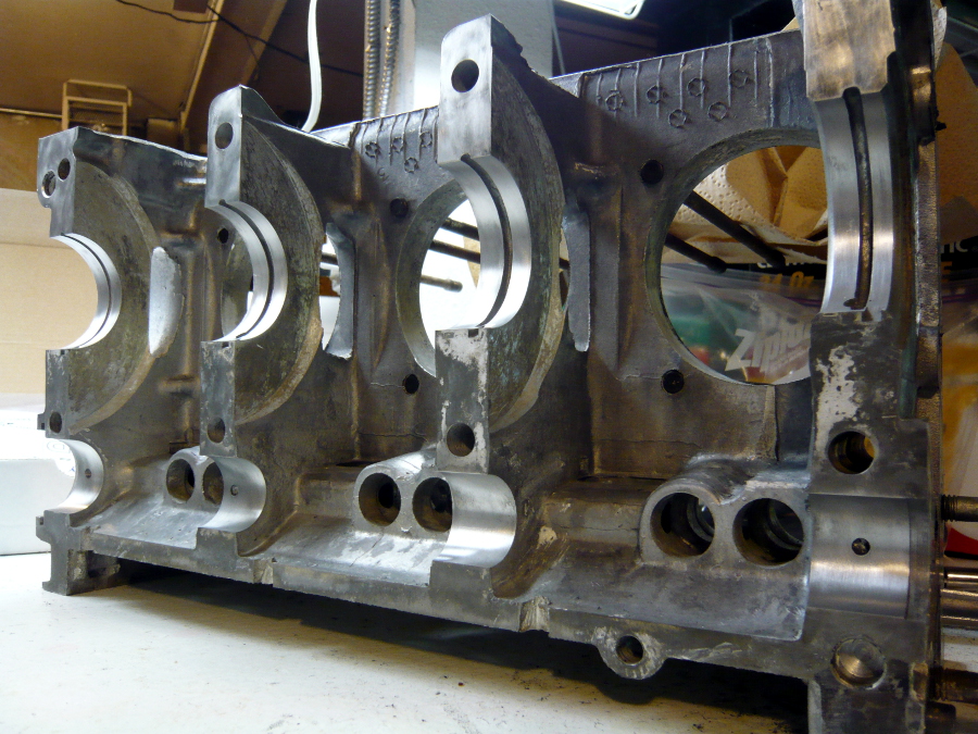
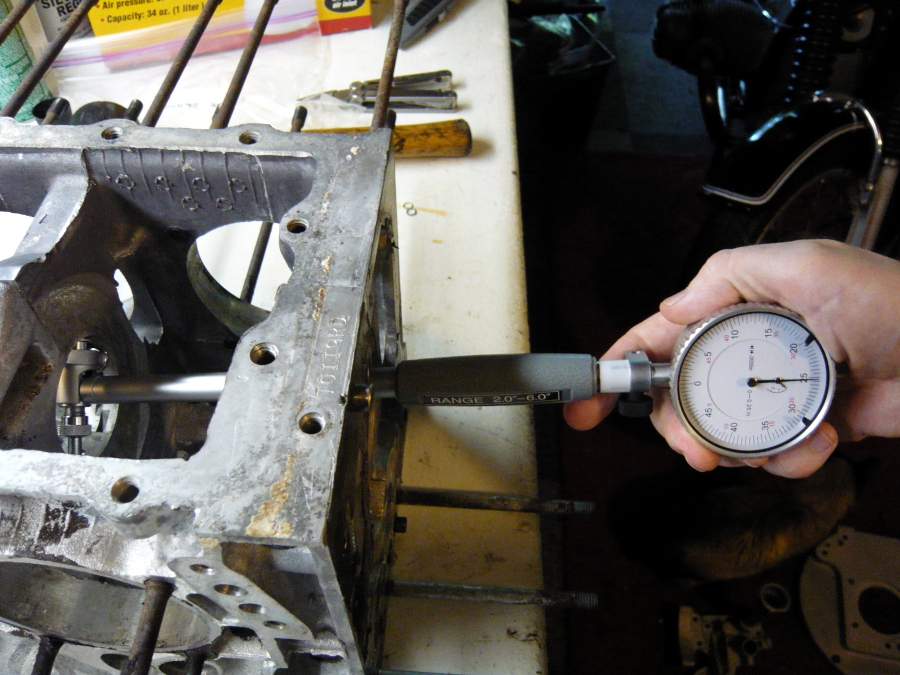
The engine build process requires bolting up and then disassembling the case hemispheres many times, and this is the first. Using the old case studs I torqued them ogether and made sure all was even: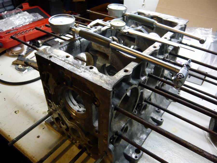
Then I used a pair of dial bore gauges to see how much variance there was in terms of side-to-side distance and out-of-roundness. Since the cam rolls directly in the journals without the aid of bearings, I thought for sure these would be way off. It turns out that there was less than half a thousandth deformation, which is right in spec. I'm a touch amazed by that. The crank journals also measured no more than a half thousandth, so I'm super lucky. For a moment I thought about having the case insides lapped, but figuring that it might throw off the crank bearing clearance I'll just clean them with a razor blade and leave them be.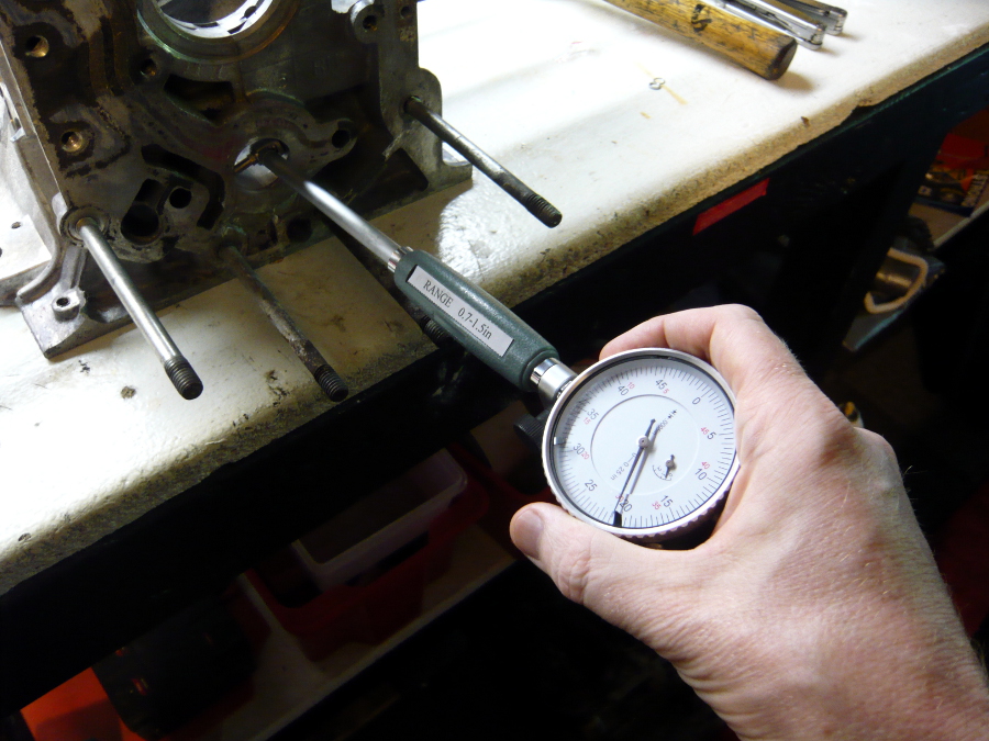
Next up is the head stud torque test. If the case can pass that, then it's a good donor. More on that when the cylinders return.
Posted by: andys Aug 9 2013, 10:03 AM
Looking good!
Comming from 30+ years of managing protoype and tool shops in the medical industry, tell me you didn't set your bore gage using calipers.
Andys
Posted by: r3dplanet Aug 9 2013, 01:37 PM
Nope. I used a micrometer. The calipers were just to get an idea of the diameter of the journals so I could use the correct anvil.
Thanks for keeping check on me!
Posted by: andys Aug 9 2013, 03:09 PM
Nope. I used a micrometer. The calipers were just to get an idea of the diameter of the journals so I could use the correct anvil.
Thanks for keeping check on me!
Good man!!!!!
Andys
Posted by: Dr Evil Aug 9 2013, 05:49 PM
This thread pleases me
Posted by: injunmort Aug 10 2013, 06:42 PM
I don't mean to be obtuse, and I certainly don't know corvair engines but you said the cam runs on the machined aluminum surface of the case without a bearing. did I understand that correctly?
Posted by: r3dplanet Aug 10 2013, 07:03 PM
Correct. I have no idea why. Apparently GM engineers didn't think cam bearings were necessary - which seems a bit unsettling. But after finding virtually no wear with the bore gauge, I've come to think that it isn't a huge deal. Apparently, my low wear is near identical to other Corvair engine rebuilds in that the cam journals just don't seem to wear down. One reason I think is that the cam sits so low in the engine that it's constantly flooded with oil. But like you, I certainly raised an eyebrow when I discovered this. Apparently this design decision has been justified over the decades.
I don't mean to be obtuse, and I certainly don't know corvair engines but you said the cam runs on the machined aluminum surface of the case without a bearing. did I understand that correctly?
Posted by: gf4c Aug 11 2013, 08:57 PM
Hello Marcus
you wrote: He ran the case halves through the parts washer but we opted not to bead blast the case hemispheres until we know for certain that the case tests out okay.
I have seen several Corvair engines ruined by bead blasting the engine case. No matter how clean you think you might have it, there are often bits of glass beads hiding and waiting to kiss your crank  You can get the case very clean with some simple green and some elbow grease, lots of hot soapy water works wonders.
you also wrote: I'm also having the old cylinders cleaned up so I can run a head stud torque test and then sell them off.
You can also run a head stud torque test with an appropriate length (and diameter) of tubing or pipe. Just slip the tubing/pipe over the head stud, add nut and torque away.
Also, Lon Wall at Corvair Underground is buying late model cylinders, he is not far from your location.
Marty
Posted by: r3dplanet Aug 11 2013, 09:34 PM
Thanks for the input, Marty. I appreciate it. Marty .. as in Marty Scarr? If so, I'm honored!
I had considered just using a tube for the head stud torque test but thought that somehow using an actual cylinder would be more realistic. I guess it technically doesn't matter. Also, since I wrote about scrapping the cylinders I've decided that have them cleaned and prepped to sell them instead of scrapping them.
The cleaning of the case halves is a vexing issue. I've heard some say never to bead blast it as you suggest. I've heard other authorities say not to worry about it. My issue is that at this point I just can't get it any cleaner with Simple Green, kerosene, Biokleen, Easy Off, or anything else I've tried. There's a metal dipper in town that uses electrolysis but that's destructive for aluminum (ask me how I know). I'd be open to other suggestions.
-m.
Posted by: DBCooper Aug 12 2013, 09:32 AM
It wasn't just GM engineers, remember who they were looking to for inspiration. Until the mid-sixties VW engines didn't have cam bearings either, the cam rode in the case. Works fine for a couple of hundred thousand miles and then the wear is enough that you can't maintain oil pressure, need either a new case or the old one machined for bearings. Hundreds of thousands (millions?) of engines. So measure the bores well, in every possible location, and especially for roundness.
Oh, and special attention to the thrust surface.
Correct. I have no idea why. Apparently GM engineers didn't think cam bearings were necessary - which seems a bit unsettling. But after finding virtually no wear with the bore gauge, I've come to think that it isn't a huge deal. Apparently, my low wear is near identical to other Corvair engine rebuilds in that the cam journals just don't seem to wear down. One reason I think is that the cam sits so low in the engine that it's constantly flooded with oil. But like you, I certainly raised an eyebrow when I discovered this. Apparently this design decision has been justified over the decades.
I don't mean to be obtuse, and I certainly don't know corvair engines but you said the cam runs on the machined aluminum surface of the case without a bearing. did I understand that correctly?
Posted by: gf4c Aug 13 2013, 09:48 AM
Thanks for the input, Marty. I appreciate it. Marty .. as in Marty Scarr? If so, I'm honored!
Hi Marcus - yes, it's me, didn't know you were such a flatterer
I thought I would come over and see how you're doing on your engine build, since you didn't get much of a welcome at corvaircenter.com
Short intro: I am a longtime Corvair guy, been playing with them (and VWs) for over 30 years, have always liked air cooled engines and cars, especially the 914 - but I've never owned one.
One method I haven't tried, but produces excellent results is ultrasonic cleaning. I looked into building such a setup, also thought about buying the $30 Harbor Freight unit and putting it's workings into a larger tank. Hasn't happened, too many projects....
Marty
Posted by: r3dplanet Sep 28 2013, 04:17 PM
Some more progress on this long term project. I'm still working on case prep. Since the last episode, my machinist tested my crank to make sure it was still good and then had him polish it and make sure it was balanced. I also bought a new crank gear, cam, and cam gear. The cam I'm using is a reverse rotation Otto-20. I've sent these, the newly cleaned up connecting rods, and a few other parts to be cryogenically treated. Gregg Hikimian is doing the work. He's a very interesting chap and has delighted me outstanding service. He also performs all kinds of space age coatings and other treatments. While I'm waiting for all of those parts to return I had my case halves cleaned, and cleaned again. I'm going to perform a head stud test (as seen below), clean off the casting flash from the engines halves with a Dremel, and then hike hike them up to American Metal Cleaners for a trip into a heat-process cleaning specifically for aluminum. Or Aluminium if you are British.
So today I'm showing the head stud test. I found a great procedure here:
http://flycorvair.net/2012/01/28/testing-head-studs/
I followed this for the most part with one small modification. But first up I had to clean up the threads on the head studs. I'm actually considering pulling all of them and replacing them with stronger studs, but the Corvair brains I've picked are very split in their opinions. The aircraft guys all seem to do it, but the automotive guys don't tend to unless there's serious problems. I have a call in to American-Pi to see what they recommend. In the meantime, I'm passing the time with important little tasks. [Hey Marty, please feel free to chime in on this issue!]
You can see that the ends of the studs (3/8"-24 using the Roman Catholic measuring system) don't look very good. So I'm using both a die and a thread chaser to clean them up.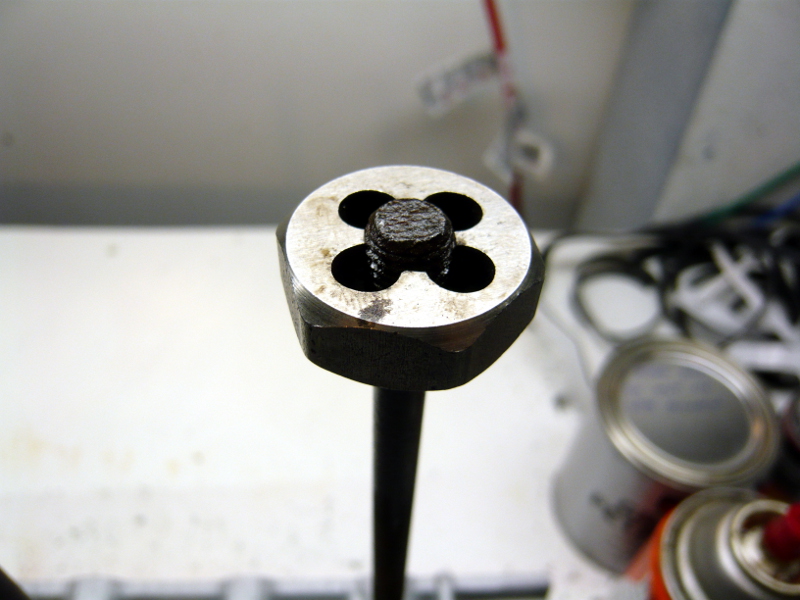
The thing about a six cylinder engine is that there's more studs than usual. The top row is where the damage is. The bottom row is shorter by an inch or so. The bottom studs also hold the rockers in place, and because they're constantly coated in oil these threads are in super condition.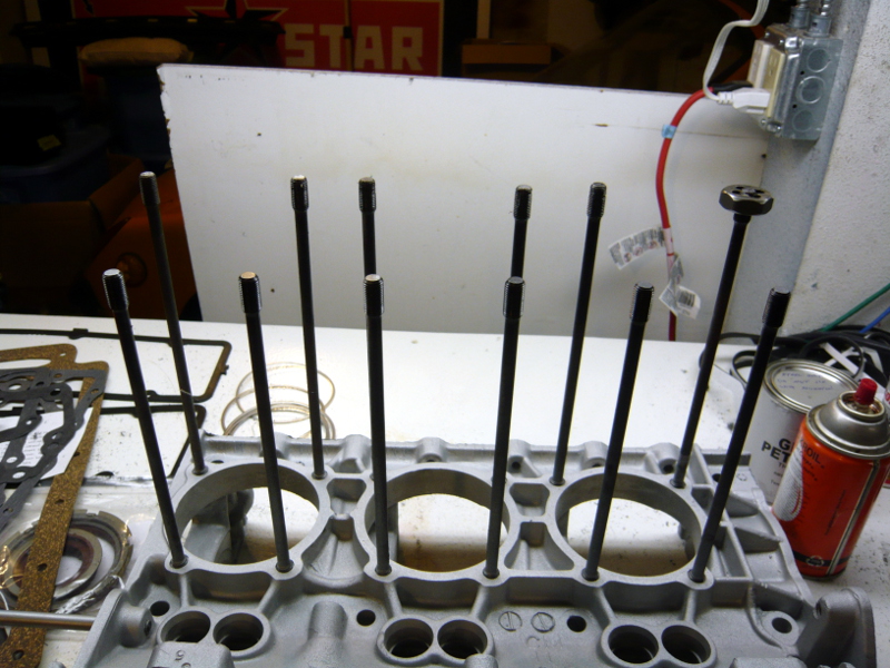
Now it's time to see if the studs can hold 30 pounds of torque. The first idea I had was just to use one of the old cylinders and torque it down with some fasteners, but you can see that there's no way to do that since any little amount of torque would just break the fins. I thought about making a square jig to fit over all four studs and the cylinder to simulate the head, but then I remembered that I don't have any machining capability. 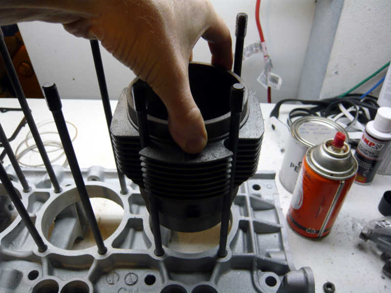
So I went to Plan B and cut some 3/8" steel tubing and used some hardened fasteners instead. This failed because the tubing begins to collapse at less than 20 pounds.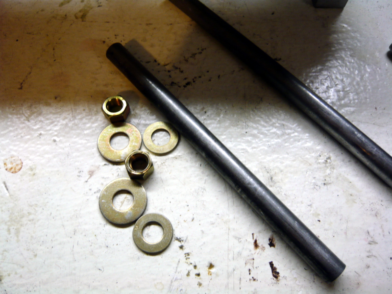
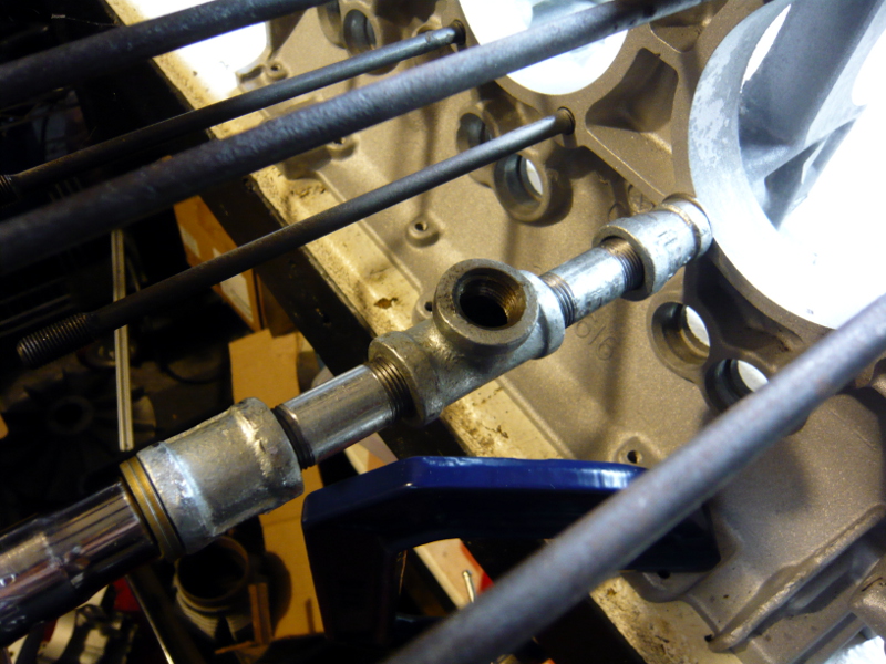
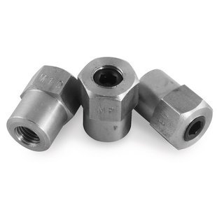
But finally the lights when on and I picked up some steel plumbing nipples of different lengths to match the stud length and still reveal the threads. I spun on a Tee so that I could view into the hole with a small light to see if the head stud would turn as I torqued it down. The tool completely obscures sight of the stud so this little idea worked really well. 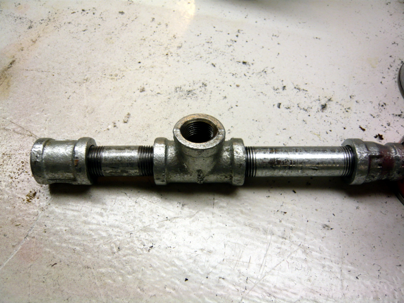
This is the final setup. Using hardened washers to protect the case surface, I torqued down the nut to 15 pounds making note of the position of the wrench handle. Then I torqued again to 20, 25, and then 30 pounds making sure that the handle didn't travel too far to meet each target. 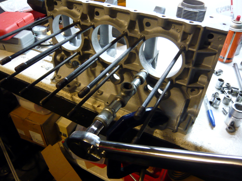
At the end of the exercise I had exactly one loose stud. I'll order a replacement from Clark's that measures .003" thicker on the base stud and Loctite it in unless American-Pi tells me to pull them. If that's the case, then I just wasted a Saturday. But hey, it's pouring down in rain Portland and this is what you do in this crappy weather.
Posted by: McMark Sep 30 2013, 09:38 PM
Porsche did the same thing until the stopped making the cases from aluminum.
It wasn't just GM engineers, remember who they were looking to for inspiration. Until the mid-sixties VW engines didn't have cam bearings either, the cam rode in the case. Works fine for a couple of hundred thousand miles and then the wear is enough that you can't maintain oil pressure, need either a new case or the old one machined for bearings. Hundreds of thousands (millions?) of engines. So measure the bores well, in every possible location, and especially for roundness.
Oh, and special attention to the thrust surface.
Correct. I have no idea why. Apparently GM engineers didn't think cam bearings were necessary - which seems a bit unsettling. But after finding virtually no wear with the bore gauge, I've come to think that it isn't a huge deal. Apparently, my low wear is near identical to other Corvair engine rebuilds in that the cam journals just don't seem to wear down. One reason I think is that the cam sits so low in the engine that it's constantly flooded with oil. But like you, I certainly raised an eyebrow when I discovered this. Apparently this design decision has been justified over the decades.
I don't mean to be obtuse, and I certainly don't know corvair engines but you said the cam runs on the machined aluminum surface of the case without a bearing. did I understand that correctly?
Posted by: gf4c Oct 1 2013, 10:43 AM
-snip-
I'm actually considering pulling all of them and replacing them with stronger studs, but the Corvair brains I've picked are very split in their opinions. The aircraft guys all seem to do it, but the automotive guys don't tend to unless there's serious problems. I have a call in to American-Pi to see what they recommend. In the meantime, I'm passing the time with important little tasks. [Hey Marty, please feel free to chime in on this issue!]
-snip-
At the end of the exercise I had exactly one loose stud. I'll order a replacement from Clark's that measures .003" thicker on the base stud and Loctite it in unless American-Pi tells me to pull them. If that's the case, then I just wasted a Saturday. But hey, it's pouring down in rain Portland and this is what you do in this crappy weather.
Hi Marcus
I don't recommend replacing any studs that pass the torque test when building a stock type engine. They are plenty strong IMO, no need for those expensive 7/16" studs which cost over $300 for replacing all 24 studs.
Regarding installing the replacement stud: Factory Manual recommends using anti-seize on the threads when installing into the block. If your threads are good in the block, the .003 will be very snug to install, the anti-seize will help. I use a special installation tool, similar to these:
These work much better than the double nut arrangement commonly used.
HTH
Marty
Posted by: r3dplanet Oct 1 2013, 10:55 AM
Hey, those are cool! Where can I find them? Or the exact name of the tool?
The only reason I thought about replacing all of the studs is because of the increased displacement and power of the 3.1 conversion. I know for a stock engine there should be no issue, but with the increased power it gave me pause.
Thanks for being here!
-marcus
Hi Marcus
I don't recommend replacing any studs that pass the torque test when building a stock type engine. They are plenty strong IMO, no need for those expensive 7/16" studs which cost over $300 for replacing all 24 studs.
Regarding installing the replacement stud: Factory Manual recommends using anti-seize on the threads when installing into the block. If your threads are good in the block, the .003 will be very snug to install, the anti-seize will help. I use a special installation tool, similar to these:
These work much better than the double nut arrangement commonly used.
HTH
Marty
Posted by: 914coop Oct 1 2013, 06:47 PM
Hey Marcus, welcome to the madness.
Got good info from Ray and with buding the turbo with both 64 & 66 parts, blow through instead of draw through, and going to a non thrbo 90 hp distributor I do not have any turbo lag. That also added $$$ for a safeguard system.
I should update my project thread, you do a much better job at documenting than I did.
Hope your mount works better than my trial and error method. Will be interesting to see what you do differently with certain thi.gs like the mount.
I am stuck trying to figure out engine lid and if I do a custom rain tray. This would be the reason I would not do the turbo again.
Be watching, Irv
Posted by: scotty b Oct 1 2013, 07:55 PM
Roller rockers have been a nice touch on mine.
Attached image(s)

Posted by: MDG Oct 1 2013, 08:17 PM
Roller rockers have been a nice touch on mine.

Oh dear . . .
Posted by: ben*james Oct 1 2013, 08:18 PM
Marcus, good talking with you today. Good luck with your project here and good teenen. Yeah, that's my word I just made it up.
Posted by: balljoint Oct 1 2013, 08:42 PM
Roller rockers have been a nice touch on mine.

:immediately stops taking prescription:
Posted by: Dr Evil Oct 1 2013, 08:45 PM
Roller rockers have been a nice touch on mine.
1/12 failure. Not bad
They guy is sending me free parts when he gets back in Oct.
Posted by: scotty b Oct 1 2013, 09:07 PM
Roller rockers have been a nice touch on mine.
1/12 failure. Not bad
They guy is sending me free parts when he gets back in Oct.HOORAY BEER !!!
Posted by: Dr Evil Oct 1 2013, 09:17 PM
Indeed. I want to take pics before I update my thread, so stop it.
Posted by: scotty b Oct 1 2013, 09:18 PM
Indeed. I want to take pics before I update my thread, so stop it.
no.... can't stop...won't stop

Posted by: Eric_Shea Oct 1 2013, 11:15 PM
Did someone say "Roller Rockers"?
Posted by: gf4c Oct 4 2013, 11:11 AM
Hey, those are cool! Where can I find them? Or the exact name of the tool?
Those ones are made by http://www.motionpro.com/motorcycle/tools/category/stud_installation_tools/ but I don't see any in 3/8-24 in their catalog. You might check with some of the motorcycle shops as the Harley guys need them in the 3/8-24 size (also available on ebay).
The only reason I thought about replacing all of the studs is because of the increased displacement and power of the 3.1 conversion. I know for a stock engine there should be no issue, but with the increased power it gave me pause.
My experience is the studs are not the weak link when making extreme power.
You mention the 3.1 conversion: If you're willing to accept a few less cc by using a 92mm piston/cylinder instead of the 94mm ones (2974cc instead of 3130cc), you can build a stronger engine IMO. The 92mm cylinder is available in a "thick wall" version; it also has a reduced spigot end diameter where it enters the case, resulting in more aluminum around the studs. Many thanks to Jeff Ballard, owner of SC Performance for this tip.
Marty
Posted by: tdgray Oct 4 2013, 11:22 AM
Just saw this thread... great stuff there Marcus
Posted by: veltror Oct 4 2013, 12:22 PM
Did someone say "Roller Rockers"?
Bay city rollers !!!
Posted by: Jeff Hail Oct 5 2013, 12:38 PM
Fun project. I like your Barracuda also.. Formula S 273 or did you just install the rally wheels?
I built a hot rodded Corvair a long time ago. I always felt Corvairs got a bad rap and that stigma alone is what killed them off. I lived in SoCal so the motor I started with had air injection. As soon as the pump and plumbing went away it ran a lot cooler which enabled the modifications to work well. I opted to go the turbo route which in the early 1980's was an interesting science of trial and experimentation in the aftermarket sector. Small fast spooling scrolls were just not around back then, everything was big snail shells and slow wind up.The electronics were just not up to the hardware at that time.
I see a lot of them around the San Fernando Valley still as daily drivers. My friends Chris had a utility truck until recently sold and Kevin has a really nice coupe he's restoring. They still have appeal.
These motors are pretty dependable designs. The valve train and rocker layout was taken from the typical V8 overhead valve designs. The block and jugs is a crossbreed of other air cooler designs. I could not help but chuckle about the bearing-less cam quote. Back when I built mine I went to order a load of parts and got that stare when I mentioned to the machine shop "crank bearings, cam bearings..oops".
I sold the car off and it changed hands a few times. I saw it about 15 years ago in Hollywood. Same license plate still on it reading " DMONIC". People would see the car, read the plate and say "Dominic nice Corvair".
Only the Corvair guys got the joke that it meant Demon - Nimonic hence the turbo parts. Still wish I had that car. If I run into again I would try to buy it back.
Good luck with yours. Once it's done I know you will enjoy it. They are fun.
Posted by: veekry9 Oct 13 2013, 05:43 PM
Some more progress on this long term project. I'm still working on case prep. Since the last episode, my machinist tested my crank to make sure it was still good and then had him polish it and make sure it was balanced. I also bought a new crank gear, cam, and cam gear. The cam I'm using is a reverse rotation Otto-20. I've sent these, the newly cleaned up connecting rods, and a few other parts to be cryogenically treated. Gregg Hikimian is doing the work. He's a very interesting chap and has delighted me outstanding service. He also performs all kinds of space age coatings and other treatments. While I'm waiting for all of those parts to return I had my case halves cleaned, and cleaned again. I'm going to perform a head stud test (as seen below), clean off the casting flash from the engines halves with a Dremel, and then hike hike them up to American Metal Cleaners for a trip into a heat-process cleaning specifically for aluminum. Or Aluminium if you are British.
So today I'm showing the head stud test. I found a great procedure here:
http://flycorvair.net/2012/01/28/testing-head-studs/
I followed this for the most part with one small modification. But first up I had to clean up the threads on the head studs. I'm actually considering pulling all of them and replacing them with stronger studs, but the Corvair brains I've picked are very split in their opinions. The aircraft guys all seem to do it, but the automotive guys don't tend to unless there's serious problems. I have a call in to American-Pi to see what they recommend. In the meantime, I'm passing the time with important little tasks. [Hey Marty, please feel free to chime in on this issue!]
You can see that the ends of the studs (3/8"-24 using the Roman Catholic measuring system) don't look very good. So I'm using both a die and a thread chaser to clean them up.
The thing about a six cylinder engine is that there's more studs than usual. The top row is where the damage is. The bottom row is shorter by an inch or so. The bottom studs also hold the rockers in place, and because they're constantly coated in oil these threads are in super condition.
Now it's time to see if the studs can hold 30 pounds of torque. The first idea I had was just to use one of the old cylinders and torque it down with some fasteners, but you can see that there's no way to do that since any little amount of torque would just break the fins. I thought about making a square jig to fit over all four studs and the cylinder to simulate the head, but then I remembered that I don't have any machining capability.
So I went to Plan B and cut some 3/8" steel tubing and used some hardened fasteners instead. This failed because the tubing begins to collapse at less than 20 pounds.
But finally the lights when on and I picked up some steel plumbing nipples of different lengths to match the stud length and still reveal the threads. I spun on a Tee so that I could view into the hole with a small light to see if the head stud would turn as I torqued it down. The tool completely obscures sight of the stud so this little idea worked really well.
This is the final setup. Using hardened washers to protect the case surface, I torqued down the nut to 15 pounds making note of the position of the wrench handle. Then I torqued again to 20, 25, and then 30 pounds making sure that the handle didn't travel too far to meet each target.
At the end of the exercise I had exactly one loose stud. I'll order a replacement from Clark's that measures .003" thicker on the base stud and Loctite it in unless American-Pi tells me to pull them. If that's the case, then I just wasted a Saturday. But hey, it's pouring down in rain Portland and this is what you do in this crappy weather.
First(second) Post
Hi Marcus-and all
I have recently purchased a cherry tomatoe '72.
I am Vic in the T.O. and have decided to follow your lead
and install an American F6 in the tail(er mittle) of my 914.
I have begun the restoration of the body/paint without the usual
sheetmetal fabrication or replacement.The car is virtually rust-free
and SoCal condition and therefore rare in the salty environs of Ontario.
The VW repair shop proprietor had installed a later 2L and TX
but could no longer devote the time or space to the project.
As it was stored indoors 10+years after a 70's repaint it only
requires some hand sanding.
Having owned a '62 Beetle in the early 70's I cannot get past the sound
of the VW-Porsche F4.There is available a '05 3.6 for 3.5K as a core locally
but alternatively I purchased 2 110 Corvairs for 0.5K instead.
The vendor decided a Lycoming O-320 was more suitable for his aircraft.
I have been reading the progress reports and dialog of so many different
sub-versions of the NARP 914's with great interest.As I now have taken the
first steps to replace the 2L I trust you are trailblazing the way ahead of me.
I have not yet put a wrench to the F6's.
I'll post again soon with pix as this is the second time I am typing this.
(typo delete)
vic
I've made my P-car blue.
Posted by: Dr Evil Oct 18 2013, 02:32 PM
Here are the pics of my roller rocker failure. It appears the circlip may have failed---> then the needle bearing ----> then the stud. Not bad as it is easy to replace.
For my 3130 I bored the case and used T2 2.0 P/C. The studs were checked and the registers opened to fit the spigots. No issues as of yet, with this part 
Marty, nice to see you here Check out my bus thread for an interesting vair build and CIS adaptation.
Attached thumbnail(s)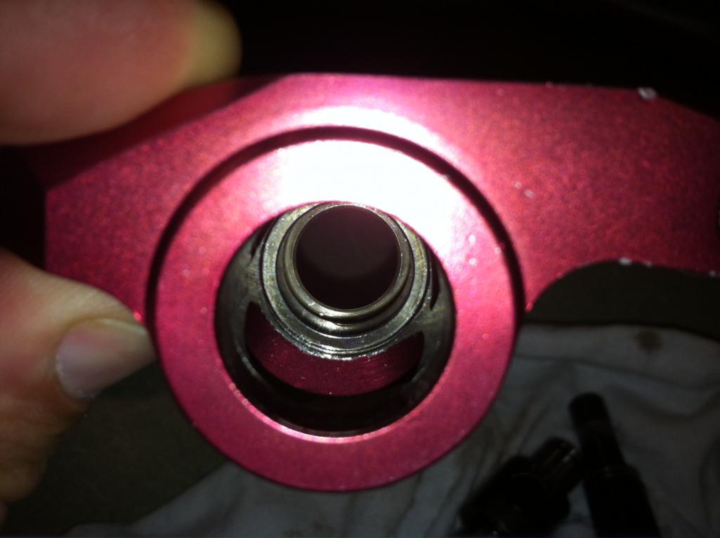
Attached image(s)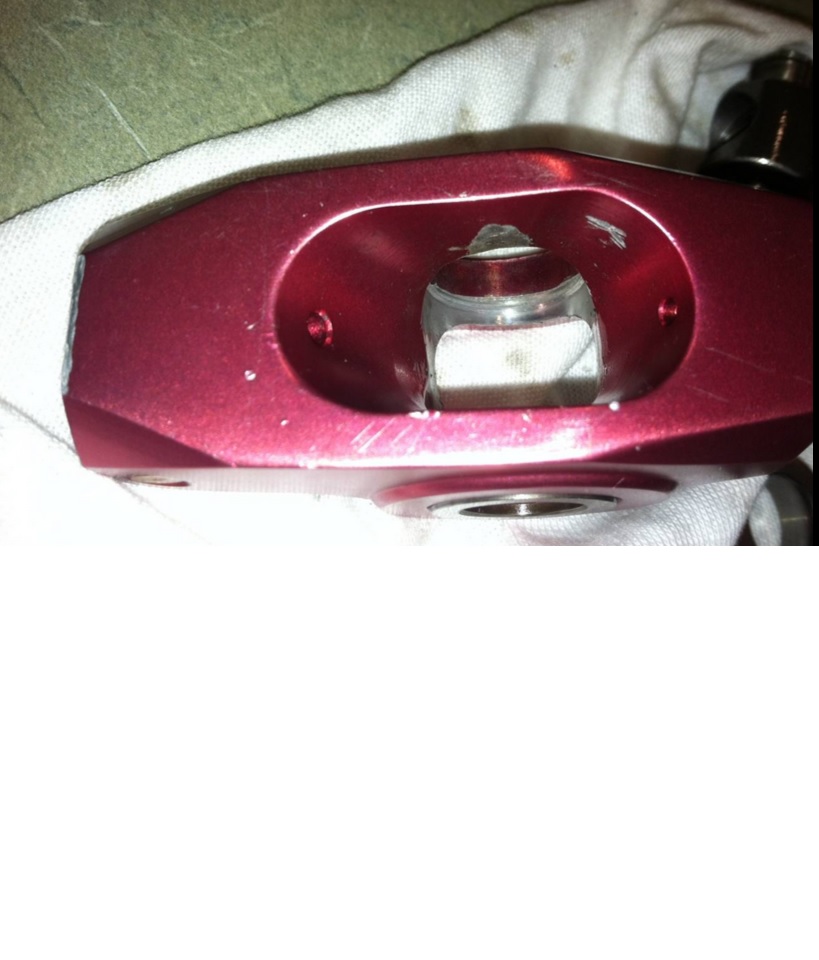
Posted by: veekry9 Oct 18 2013, 04:59 PM
Greetings Dr. Evil.I am Vic from across the lake in TO.
I am currently embarking on the path
of a Corvair powered 914 and have read
of your trials and tribulations.
Your converted bus is neatO.
I presume you brought it North for your clinic
recently.I have been considering the products
offered by CorvairSpecialties.A inquiry on the
other site was immediately flamed.What you
describe is a proper response from a vendor,
much like Bruce Crower's response to a
customer.I am therefore confident to make
a purchase of some parts.The rocker covers
appear to be the Clark,s product.I have
heard only positive feedback re their service.
A vehicle out of production since '69 yet
the support is meeting the demand.
It's wonderful,isn't it?
You may be correct as to the failure mode.
However,the pix of the rocker stud failure
may be a sign of a stress crack in the
weak point of the stud,at the root of
the thread/shank interface.
The photo clearly shows the edge
of the thread runout.The proper
heat-treat of the studs is what gives
them their strength.
I will test,like you,the parts durability and
performance.
Posted by: r3dplanet Jan 20 2014, 02:17 AM
I'm not dead yet.
However, I am totally bummed about my Mars-One application being denied with a stupid form letter. Seriously. I've written better notes on paper napkins at late night diners. I think those bastards would reconsider if only they had brains to realize that I was always the ideal candidate; it's obviously their selection criteria that's faulty. OBVIOUSLY. Two words for them: Apollo I. Now that my life has no meaning again, I'm back to working on my Corvair engine.
There will be a bunch of updates soon. Over the past few months I've had a bunch of bottom-end parts (crank, cam, etc.) crogenically treated. After getting them back I sent the crankshaft off to be ground, polished, indexed, and balanced. It should be available any day now. In the meantime I've been slowly, slowly, slowly cleaning and polishing the secret innards of the case halves. The part I'm not going to reveal to anyone is the probable application of GE Glyptal paint to the interior. It's a hot button topic and I totally don't care about that controversy. We can argue, classic Greek-style, all day long on another thread about it's merit. While we're at it we can punt around PC vs Mac, Coke vs Pepsi, Girlfriend vs Your Mother. Frankly, I enjoy making arbitrary decisions and then following through with them. Like Glyptal paint. Makes for good mental exercise.
I have also collected other parts including all of the remaining reverse rotation parts like cam gears, idlers, and alternator fans. The new Melling lifters are here. And I've contracted out to have a pair of custom-made intake manifolds produced to accomodate my Weber 44 IDF carbs that are currently powering my 1.7 liter engine with the magic of 28mm chokes. That gentleman is Tom Knoblauch of American Flat 6 fame. He normally produces intakes for the Weber 40s, but he agreed to make intakes for the 44s just because he's cool. The charge is $275 for the pair, which I feel is extremely reasonable.
In clutch news, I found a specialty 215mm 130-tooth conversion flywheel that will allow me to use the standard size clutch and pressure plate for the 901 transmission. Previously I had a Bus conversion flywheel (180mm) and clutch pressure plate that I bought as a VW reverse rotation kit. To this day I don't know if it would have worked in the 901 or not. Maybe some long winter even as I loaf about with my cats grieving over my past mistakes I'll pull out my old tail-shifter and see how it would work. In other news, I have a VW bus clutch, pressure plate, and 180mm conversion flywheel for sale.
I also ended up buying an Otto-20 reverse camshaft from Clark's to replace my previously purchased stock specification reverse cam. That cam is now also for sale.
Somewhere along the way I found myself staring at upright 914-6/911-style cooling fan/shroud combos like this one:
http://www.thesamba.com/vw/forum/viewtopic.php?p=3833213
.. But they require a load of bread to capitalize. Star Cooke sells the complete package of shroud, fan, and alternator for $1500. When poking around eBay I was unpleasantly surprised to find that the 911 fans alone cost $300-$600. Add in another $200 for the magnesium housing. And another $200 for the alternator. Earlier this week I looked at having a fabricator make just a fiberglass shroud from the original molds from back when they were more commonly sold. It looked to be doable right up until I realized that I don't want to spend that kind of money on a fancy fan. Anyway, as it turns out they don't cool effectively due to the lack of correct internally baffling to direct the airflow. My hopes for coolness have become dashed, and it feels exactly like having a crush on a Playboy bunny only to realize that she's half my age and I'm forty and all she wants to talk about in real life is scientology and Justin Bieber.
So soon there will finally be some actual assembly for your viewing pleasure. All that's left now is raising capital for some 140 heads and the machine work for the VW piston & cylinder conversion machine work. If someone finds some money laying on the sidewalk please throw it into an envelope and send it to me so I can steam the stamp off of it.
Forward, comrades. Thanks for being patient for the World's Slowest Engine Build.
-marcus
Posted by: r3dplanet Feb 22 2014, 05:04 PM
So let us sit upon the ground and tell sad stories of case preparation. While I really dig the design of this six cylinder engine, I dislike the "let's crank out fifty more of these before lunch" attitude GM seems to have had in terms of production. In my not-at-all humble opinion this always irked me about the American Big-3 - often some very cool engineering ideas but watered down to hit a price point.
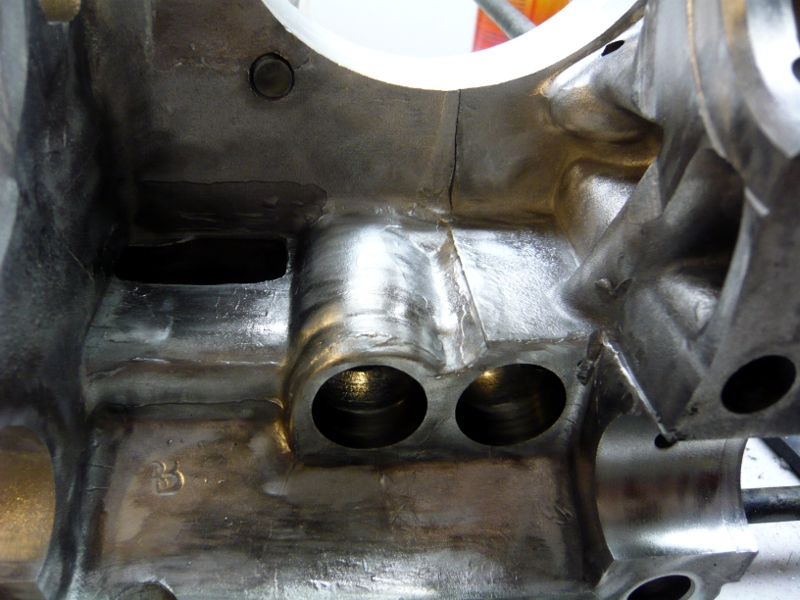
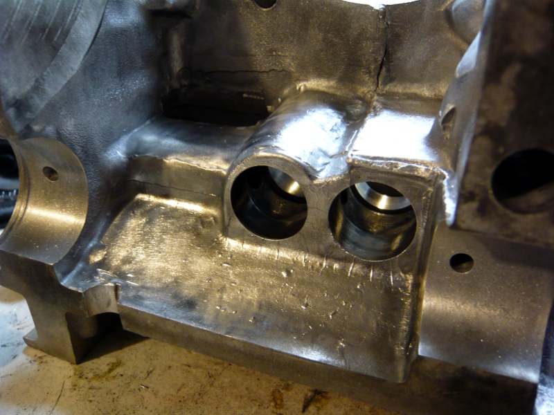
Take this aluminum case for example. I like that the case is just big enough to provide for six cylinders. I love that the rotating assembly just fits inside to maximize a small space. The construction is strong and simple. But these were obviously not hand built by German union labor who cared about their craft. Observe the crazy volume of casting flash in the block hemispheres: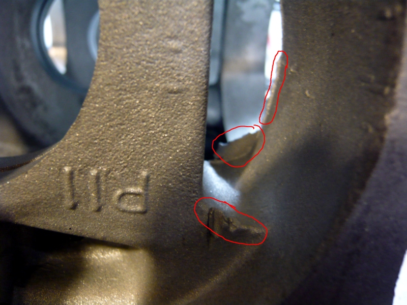
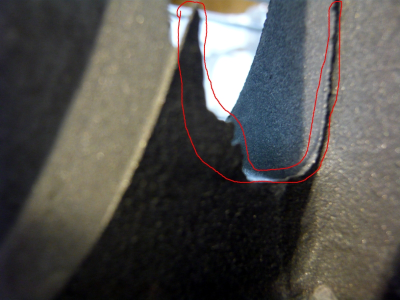
Also observe how the oil drain holes on the bottom of the case don't even match up. For that matter, neither do the tops of the walls for the journals. Luckily, I can easily clean all of this up. Specficially, I bolted the case together and used a 7/16" drill bit to clean up the drain holes.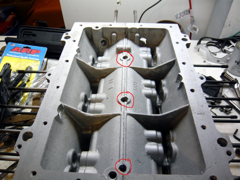
That's actually the good news about all of this. GM may not have cared about this, and clearly the engine ran for 40 years before failing. However, Marcus DOES care and was rewarded with a HALF CUP of casting flash at the end of the exercise.
[shameless plug]
It's also time for an unpaid commercial plug: Here I'm using the my fourth and LAST DREMEL EVER to remove case flash. Pro Tip: I finally got sick of replacing Dremels every few months so I replaced it with a Proxxon rotary tool (part #FBS 115/E) made by the nice people living in Luxembourg. Matched with a Flexishaft, this tool is superior in every way. It's quiet. It's comfortable. It has an adjustable chuck instead of a 1/8" collet so you can use a far wider array of bits. Another Pro Tip: McMaster-Carr has a ton of rotary bits that cost half of what Dremel bits cost and last longer. For example, I bought eleven brass cone brushes for $1.48 each. It's a money saver for sure.
[/shameless plug]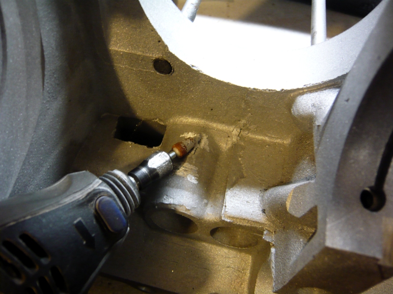
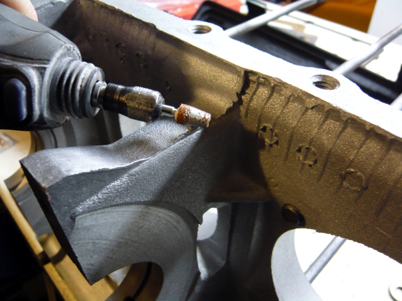
The part that took the most amount of time were the valleys above the center of the lifter bores. There were casting pockets full of little bits of crud; something like an undersea cave system. This took some serious time to grind down. It also reinforced my plan to proceed with an application of GE Glyptal paint.
Posted by: r3dplanet Feb 22 2014, 05:26 PM
When the week of grinding had finally come to an end, it was time to make some decisions about the case. For example, in the very handy book Performance Corvairs: How to Hotrod the Corvair Engine and Chassis, it is recommended to widen each of the oil passages behind the main bearings to 3/16". Indeed, the passages are supposed to be 1/8" from the factory but they actually waver all over the place from .09-.14". I called up Corvair engine machinist Ray Sedman to ask about this, but he said it's better to try to even them out to just a hair over 1/8" and then cut them slightly deeper. This way you get more oil flow as well as the full surface support for the bearings. Grand idea. When the case goes to him for the VW cylinder modification he'll take care of that with a big expensive machine.
Also, some have repeatedly told me not to remove the oil gallery plugs when performing case prep for fear of something or rather. But for the sake of completeness I wanted to open them up anyway, especially since the case was glass bead blasted and knew the case would get cleaned about a dozen times before final assembly. Check it out:
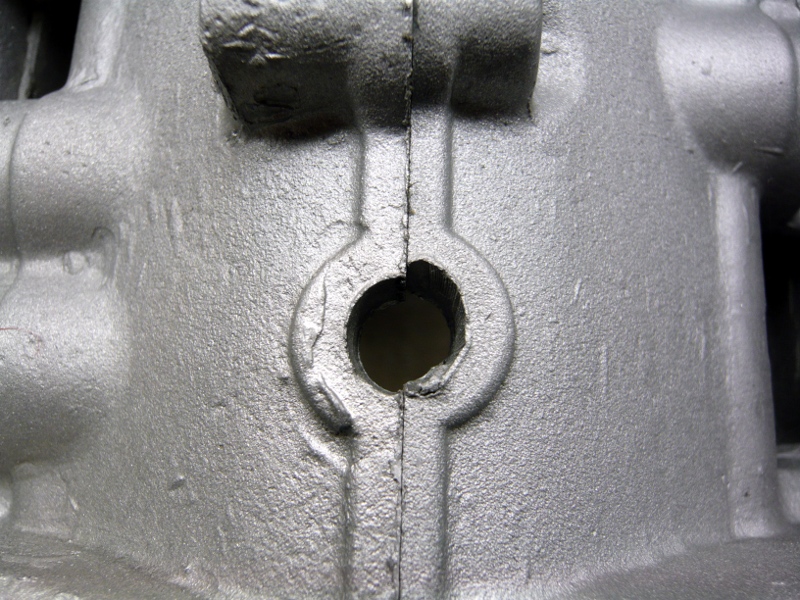
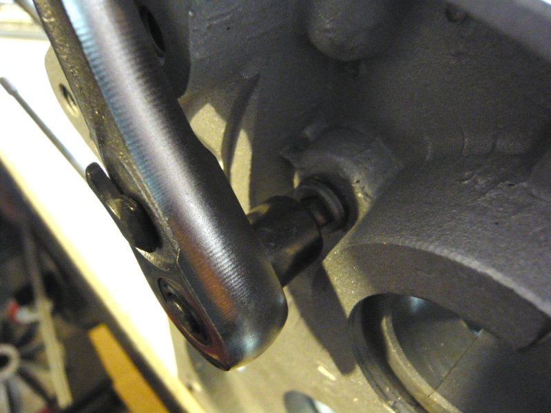
The two case plugs are 1/4" NPT plugs with 1/4" square drive sockets. They're made of steel and held in place with some sort of sealant. I used a 1/4" ratchet to remove them but would have preferred a perfectly square tool without the ball on the side.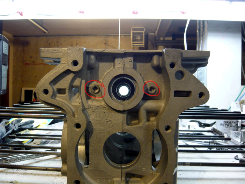
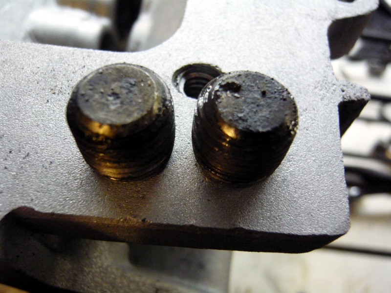
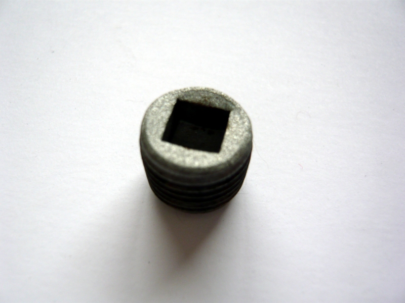
In later years, GM replaced these with aluminum hex-socket plugs and so will I. You can see the oil galleries are about as clean as a coal mine even after the case has been blasted and pressure washed a couple of times.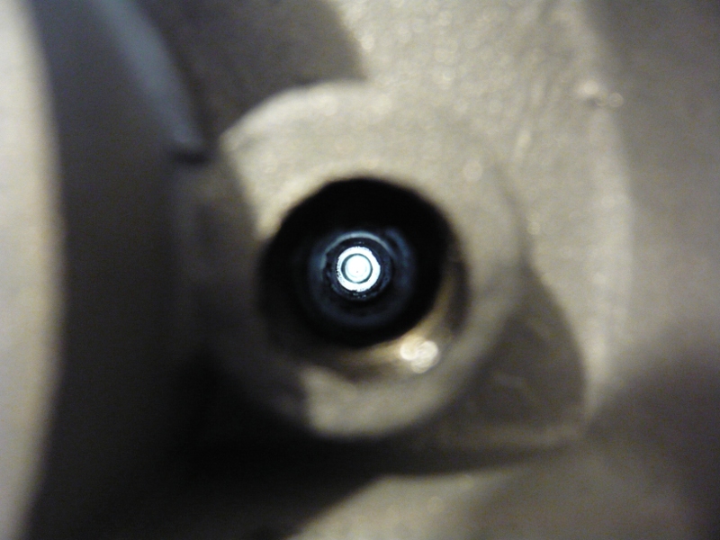
So it's a series of brass engine case brushes from FLAPS to suggestively clean the gallery, which with a little kerosene worked like magic.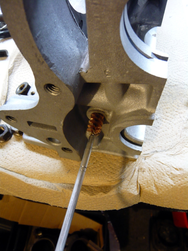
Posted by: r3dplanet Feb 22 2014, 05:53 PM
Now that the case is clean it's time to really clean the case. And I mean Mommy-Dearest-toothbush-and-bleach-on-the-tile-floor-clean. Why? Glad you asked. First, I'm polishing the innards of the case for the sake of removing unseen debris - like rounghess, impregnated glass, microscopic bits of this and that. I could have left it there but since I'm taking the extra step of painting with Glyptal paint, the surface needs to be operating room clean.
First: brass brushes and the last moments of my crappy old Dremel before switching to the Roxxon.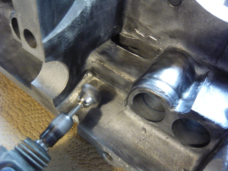
And then the whole of the engine gets cleaned with a thousand coffee filters and denatured alcohol until no discoloration can be seen on the white coffee filters. Coffee filter paper is cheap, strong, absorbent, and lint-free. They're the perfect tool for the job. After the coffee filters come the Q-tips, with which I used half a box, in order to really make sure that no dirt was left in any of the many many hiding places.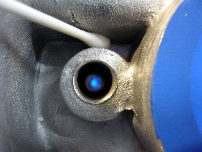
While I Was I There I took some more time to find more casting flash and more things to polish. My favorite gem by far is this oil return "hole." When I first found this my heart skipped a beat thinking that it absolutely must of have been a piece of crankshaft or bearing or something exploding right out of the case wall. Actually, this is GM's idea of a machined oil passage. Just like snow flakes, no two Corvair engine oil passages are the same thanks to what looks like a quite a blast. I polished this with great care.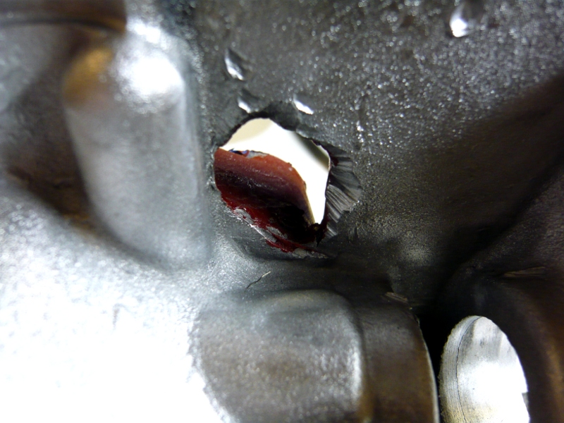
This also seemed like a great time to clean out the threads for the oil pan, top tan housing, front oil cover assembly, etc. After which I cleaned them out with Q-tips, Kroil, and alcohol.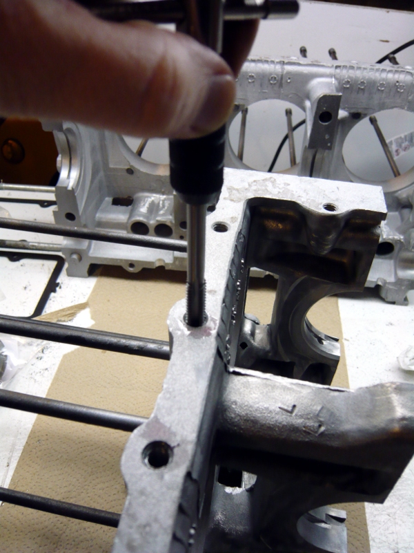
Finally, this case half is clean enough for Glyptal paint. In reading over the requisite number of Glyptal paint scare stories I found they were usually forwarded with statements like, "I don't know why this paint flaked off since I gave it a quicky clean with WD-40 and didn't bother to bake it properly afterward." Since profound cleanliness is required, profound cleanliness was executed. All told, the cleaning alone took about four days of part-time work, after a week of part-time case polishing, after another week of part-time flash grinding.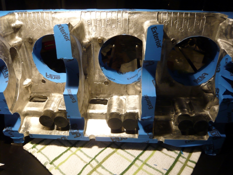
Posted by: r3dplanet Feb 22 2014, 06:23 PM
Okay. It's time for a little paint.
I gave the cases one more wipe down with denatured alcohol and compressed air. Since Glyptal is toxic, especially to people with delicate constitutions like myself, I worked one area at a time, separated by one day each, even though I was wearing a respirator and goggles. The directions on the can say to use an appropriate brush. So I used a series of 1/4" natural bristle, acid-proof model paint brushes from the hobby store.
First the inside, and then after drying some more cleanup on the next side.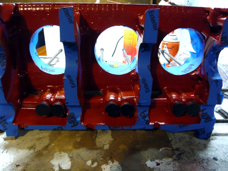
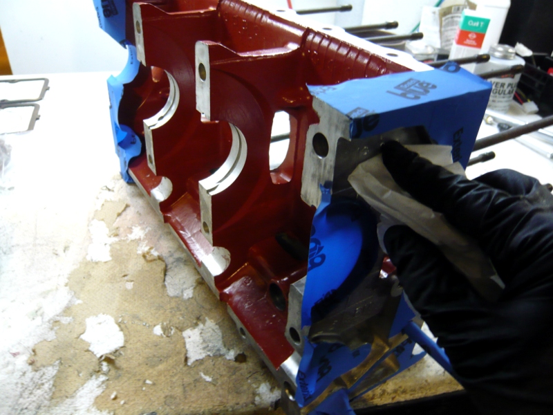
I was bummed to discover that the blue masking tape didn't mask very well, so I switched back to green which did a near-perfect job. Important tip: remove any slop like this with Xylene and a brass brush before it's baked on. After it's baked on there's little to be done about removing it except grinding or blasting it off.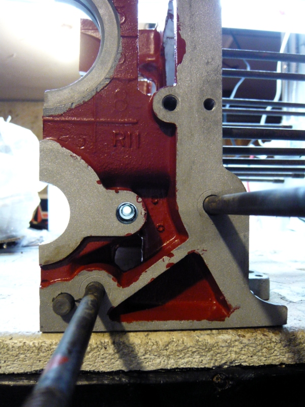
Then the bottom: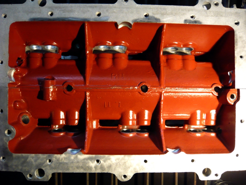
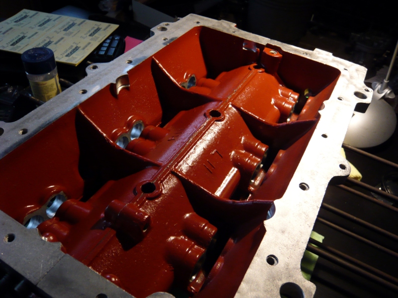
It was freezing in my garage at the time but I used my trusty Perfection Oil Heater to keep it warm for the duration. Glyptal takes a while to outgas, so it sat around for a week while I painted the other hemisphere before baking. Finally, here's a lovely smooth brick red glow after baking at 250F for two hours. And yes, this is my living room table. Since I'm a bachelor, I can get away with taking photos of the block on any surface I choose. Plus it's more fun to watch Starsky & Hutch re-runs this way.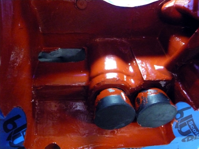
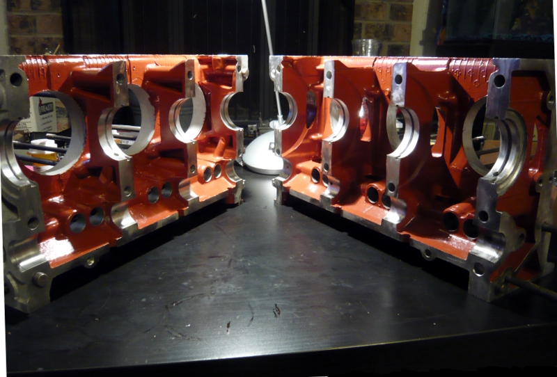
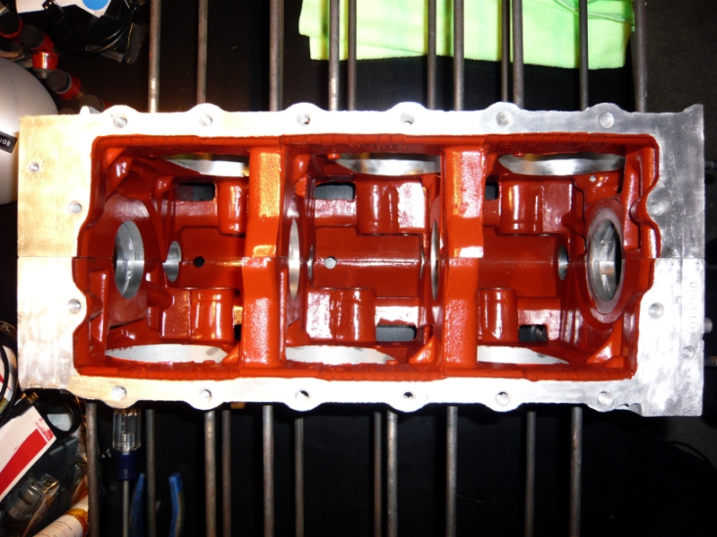
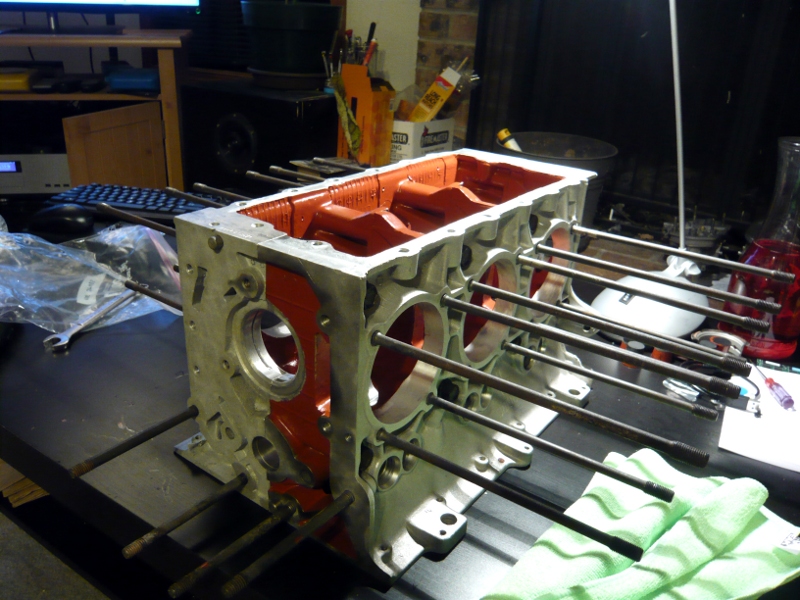
Some of the more observant viewers might see that the cylinder bores had a little paint bleed on them. Not to worry. What couldn't be removed easily will be machined off when it's time for the VW 94mm cylinder prep.
Posted by: r3dplanet Feb 22 2014, 07:16 PM
The biggest score I've made thus far are the heads. After a series of false starts I bought a pair of heads that were, astonishingly, rebuilt by Ray Sedman of American-Pi, the very same machinist doing the big bore conversion work. These were rebuilt twelve years ago but never used. One or two of the fins look to need a gentle bend, and they've already been deflashed. Most photos of Corvair heads I've seen have more flash than the case, and all of the major Corvair books strongly suggest to spend a few hours with a file through the fins. These are super, but I'll probably spend some time with a small file picking and cleaning anyway.
These heads are TITS! Wider and deeper seats, stainless valves, titanium spring retainers, silicon/aluminum/bronze valve guides, heat treated valve locks, high squish chamber machining, chrome-moly retainers, new cylinder mating surface, etc. The friggin' WORKS... for $700 from a true gentleman who bought them and never used them after spending $1575 in Year 2002 dollars.
For all the detail I'm putting into this thread I apologize that I have no photos of their rebuild process, but here are the pics that I took today.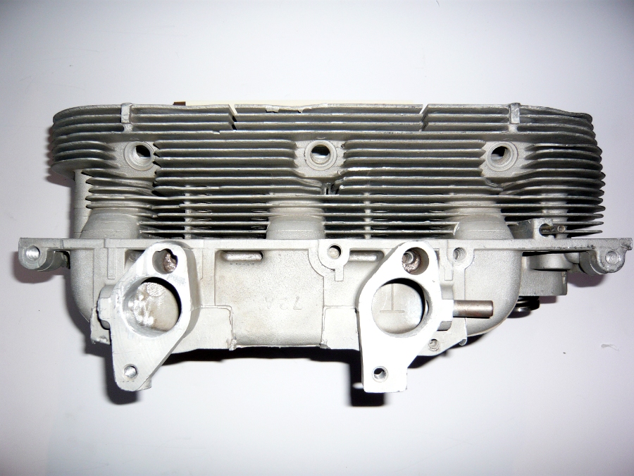
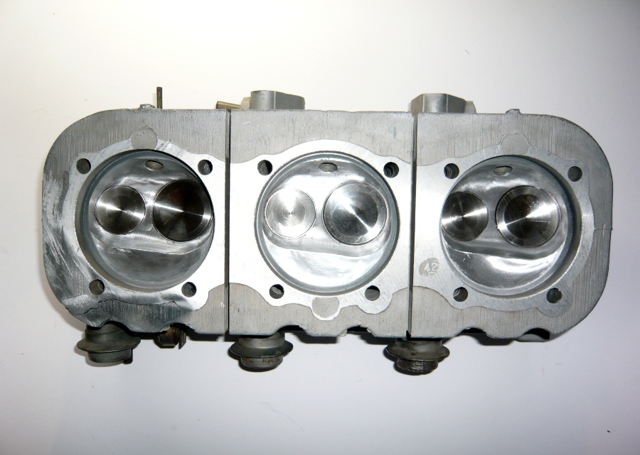
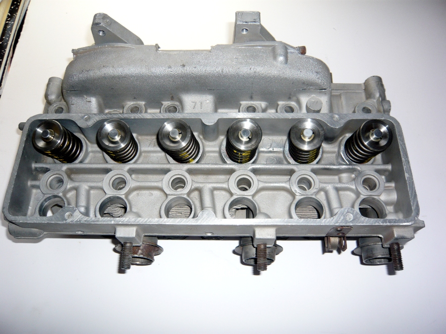
This means that as of now I have all I need to deliver the parts to American-Pi for the VW big bore conversion. My plan is to drive them to LA from Portland myself because there are friends I want to visit there anyway. This will take a few months easily. In the meantime, all of the crank/cam/rolling assembly is back from cryogenic treatment and off to Gary the IncrediMachinist to be balanced.
More after a while.
Posted by: Dr Evil Feb 22 2014, 09:17 PM
Wow, man. Thanks for the coverage. You are meticulous. Makes my build look like a monkey did it (low hanging fruit for the trolls, there). 
Posted by: DBCooper Feb 22 2014, 09:48 PM
Really enjoying your build, Mr. r3dplanet, and that's coming from someone who would rather flop his dick onto an anvil and hit it with a very large hammer than ever deal with a Corvair engine again. Go dude, GO!
Posted by: Vacca Rabite Feb 22 2014, 10:53 PM
...But they require a load of bread to capitalize...
And that, my friends, is how you work Ghostbusters into a thread on 914World.
Well done! I award you a slimer!

ScottyB, please take note.
Zach
Posted by: r3dplanet Feb 22 2014, 11:17 PM
I just want to do this job once. Certainly this is a build where I'm going bananas, but I enjoy going bananas with this sort of thing. Besides, I covet your CIS system. It makes my dual Weber 44 setup look like.. um .. 1960s technology.
Wow, man. Thanks for the coverage. You are meticulous. Makes my build look like a monkey did it (low hanging fruit for the trolls, there).
Posted by: r3dplanet Feb 22 2014, 11:18 PM
That, sir, paints quite a picture. Please do not do that. Unless you're a clown and use a balloon for a dick; in which case please upload a video.
Really enjoying your build, Mr. r3dplanet, and that's coming from someone who would rather flop his dick onto an anvil and hit it with a very large hammer than ever deal with a Corvair engine again. Go dude, GO!
Posted by: r3dplanet Feb 22 2014, 11:20 PM
AH HA! I knew someone would chime in. I'm glad it was you, Zach! It's just that Dan Akroyd is do damn quotable. Especially for Gen X-ers like us. I may also work a few The A-Team references in here somewhere.
...But they require a load of bread to capitalize...
And that, my friends, is how you work Ghostbusters into a thread on 914World.
Well done! I award you a slimer!
ScottyB, please take note.
Zach
Posted by: DBCooper Feb 23 2014, 08:52 AM
Well, I'm probably exaggerating a little. My experiences were long, long ago, I was ignorant, and as everyone knows, ignorance can and should be painful. On the other hand it's a pleasure to see it done well so I'm enjoying watching you do that, and am curious to see how it turns out.
That, sir, paints quite a picture. Please do not do that. Unless you're a clown and use a balloon for a dick; in which case please upload a video.
Really enjoying your build, Mr. r3dplanet, and that's coming from someone who would rather flop his dick onto an anvil and hit it with a very large hammer than ever deal with a Corvair engine again. Go dude, GO!
Posted by: sixnotfour Feb 23 2014, 08:04 PM
I started with Corviars, air cooled, 6cylinders, turbos , oh ya.....then found an overhead cam aircooled six cylinder.....no push rods from that point on....its a quote in some engineers book BTW
Lots of fond memories, Have Fun and it was nice to never adjust the valves...
Posted by: r3dplanet Mar 18 2014, 10:35 PM
So, I've been spending the past few weeks learning how to apply new and better coatings. I'll detail some of my experiments here, although Mark Henry is doing many of the same things right now on his thread and probably provides better explanations.
Specifically I'm experimenting with Techline dry film and ceramic coatings, KG Gun-Kote, and powder coating at home.
I'll start with powder coating. I picked up Eastwood's powder coating kit for tinkerers and I must say that it's already saved me quite a bit of money. Every powder coat place in town charges a $125 minimum, and the Eastwood kit costs the about the same. Certainly shops need to charge minimums and I don't have a problem with that, but when I need just a few little parts or different colors this process totally saves the day and has paid for itself already with the half dozen parts I've coated so far. The process is easy, almost foolproof, and provides excellent results.
In addition to the tried-and-true basic powders like satin black, gloss black, machine gray ("grey" for the British amongst us), Porsche silver, etc. I've also picked up some high temp silver ceramic/silicon powder for things like pushrod tubes. The one splash of color I'm indulging in is RAL color #1028 - the closest color I can find to Signal Orange. From England I ordered a RAL color fan (K5 Classic with high gloss) it's extremely handy since most powders I can find are sold by virtue of RAL colors. RAL #1028 isn't a dead ringer for Signal Orange but it is quite close. Certainly closer than Nepal Orange. Close enough for highlights.
Today I'm coating my cooling fan. It's made of magnesium, extremely pitted, and very hard to clean. Any drop of water will instantly oxidize the magnesium, so I had to clean it mechanically and clean after that acetone. I walnut blasted the fan several months ago and you can see that the color is typical for oxidized magnesium. 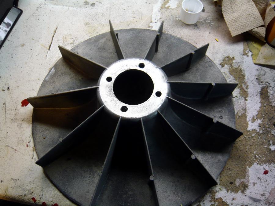
So I gave it quick blast with more walnut and then set to work with the Roxxon rotary tool. This took a couple of hours with various bits, but it eventually came clean, and was followed up with good scrubbing of acetone and denatured alcohol.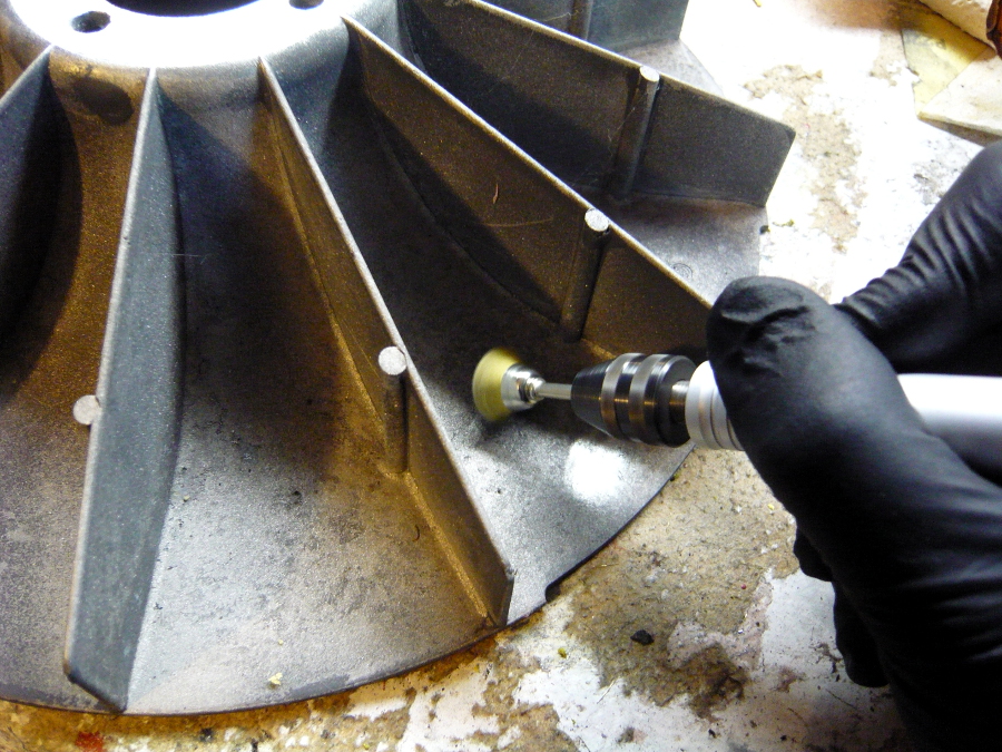
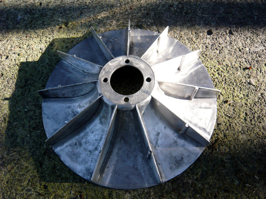
In addition to the $40 large size counter top oven I bought from a junk shop, I also picked up a large assortment of high-heat resistant silicone plugs and caps. Experimenting with powder coating has taught that one of the most important steps is to make sure one knows exactly how to mount the part into the oven without fiddling and mucking up the powder after it's been sprayed. In the this photo I have the fan sitting directly on the rack to preheat it to 150 degrees, but in the final curing I placed it silicone-plug-side down on a thin cookie sheet and practiced getting it into and out of the oven.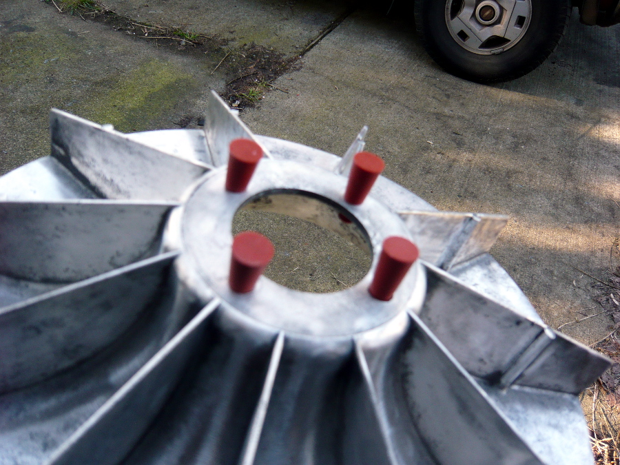
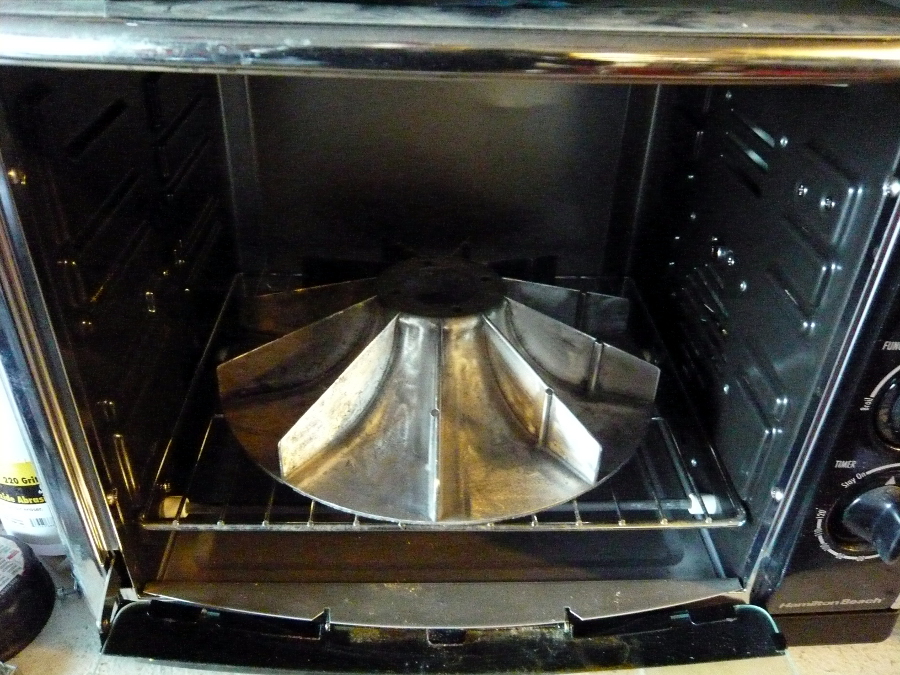
This is Eastman powder #10137, or "Orange Yellow." I was surprised to find this color which is exactly RAL #1028. Otherwise I would have to pay $75 for custom color mixing. Good deal. Signal orange 914 owners, please memorize that number. Here it is in a two pound can. In real life it looks exactly like the powdered cheese one might encounter in a box of industrial/prison/orphanage grade mac-and-cheese. Thankfully the color does tone down a bit on the finished product.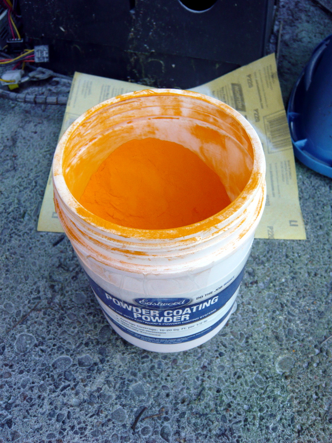
Here it is strung up and ready to go, and then with the powder applied.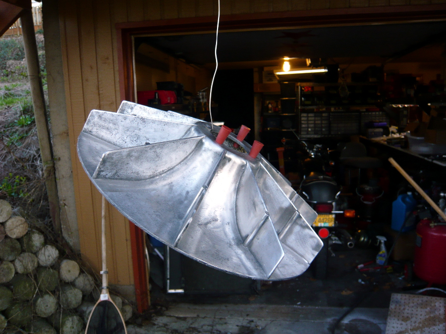
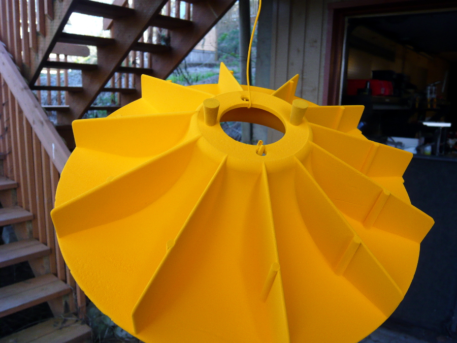
And finally into the oven. If you look closely you can see a goofy image of me taking the photo with my trusty Lumix camera. It has a certain "I take pictures of you when you're sleeping and I know when you're alone" vibe to it.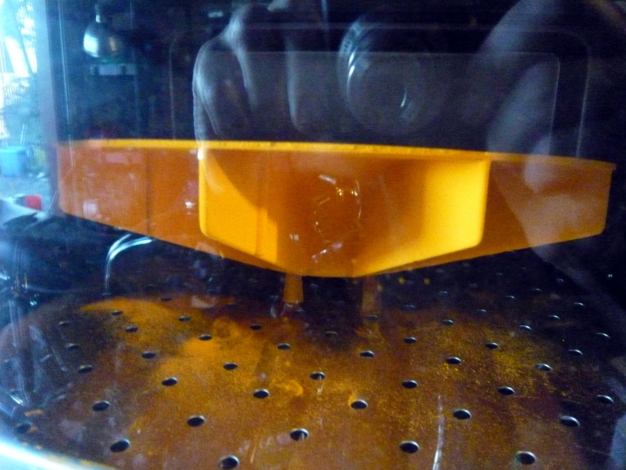
Posted by: r3dplanet Mar 18 2014, 10:46 PM
I stared at it for twenty minutes or so until it gelled over at 450 degrees Fahrenheit (*), then let it bake for 400 degrees for another 25 minutes. Here's the final product. You can see that it's still quite pitted but that just can't be avoided with a weathered, fifty year old part that's seen action and abuse. However, in real life in looks much better and smoother than the photo. I didn't want to add any filler to smooth it out because I didn't want to throw the fan off balance. There are also a tiny few spots where the powder didn't take to oxidized sections that I didn't grind down far enough; but it will never show and it will never rust so I'm not worried. Having said all that, I'm quite pleased with how it came it. It's a half-shade darker color than the car, but I can easily live with that. For the most part, it looks great.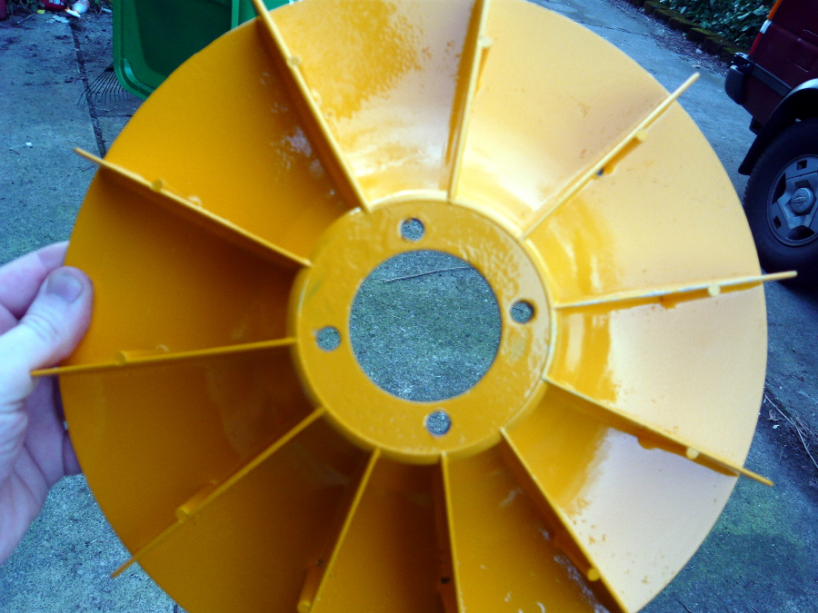
(*) Fun Fact: The Daniel Fahrenheit temperature scale is based on the lowest temperature he could make in the lab with alcohol and brine, or what he determined would be zero degrees. The high point was based on the human body which he scaled to 100 degrees. By repeatedly poking his extremely patient wife, Wilma, with thermometers he achieved his points and scale. But it turns out that she often had poor health with fevers so it's a bit high. Corrected for non-fever, it's 98.6 degrees. I wish so badly that we used the Metric / Centigrade system in the States, but frankly the goofy system we have is a LOT funnier.
Posted by: rsrguy3 Mar 18 2014, 11:14 PM
I am watching with a keen eye as I'm seriously considdering the corvair as the power plant for my Q2 homebuilt.-G
Posted by: r3dplanet Mar 18 2014, 11:20 PM
On to the air baffle.
The air baffle sits underneath the fan and fan housing but on top of the crankcase. Normally the baffle isn't coated with anything. In fact, I had a hell of a time getting it clean. And by clean I mean CLEAN. Old gasket fragments and gasket sealant really likes to stick. I didn't want it to rust when installation time came so I thought that I should have it zinc or cadmium plated. That would have been best. Powder coat would have been too thick and may be in an environment where the powder coat could melt. But then I thought about my plan to paint the cylinders with KG Gun-Kote because it's extremely thin, more durable than barbeque paint, extremely hard, and super heat proof. Plus, I can apply it at home. If I had a bunch of parts for this application, I certainly would have had them zinc/cad plated. But like powder coating, it's all about maximizing the minimum cost.
You can buy Gun-Kote in a rattle can from another manufacturer, but I went ahead and bought the industrial version. It's water based and the solids in the bottle take forever to mix. Even after throwing in some clean nuts and screws to work out the solids, my first attempt had lots of mucky particles due inadequate mixing. The second time around I mixed it for a half hour and finally achieved a good consistency. I also tried spraying with a Preval canister but it didn't work as well as I wanted to so I used a small touch-up HPLV gun that I picked up at Lowe's for $20. It worked perfectly.
So let's start with the cleaning process. Lots of chemicals. Lots of time with the Roxxon tool. Lots of time sanding. I *hate* sanding which is one more reason I'll never be a body guy. Those guys are some sort of wizards or something.
Almost clean: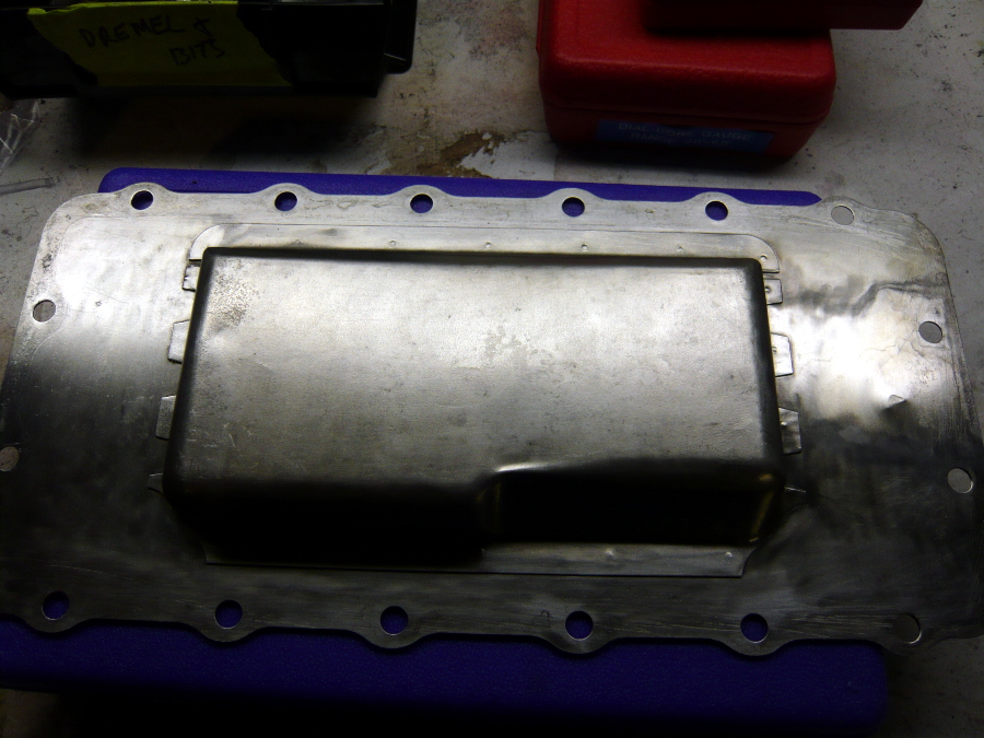
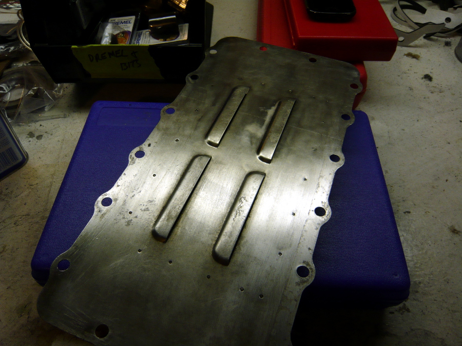
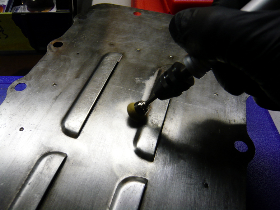
It's amazing how much dirt still hides in the pores of the metal even after a couple of hours of cleaning. Not for long though.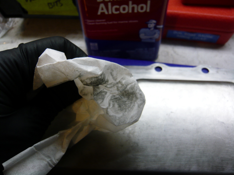
Finally, it's CLEAN.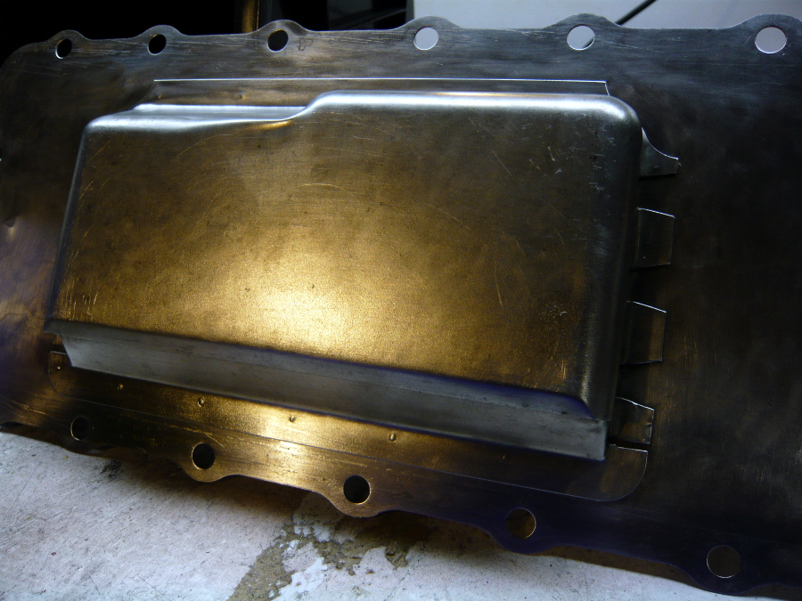
Not unlike powder coating, I like to preheat the part to 150 degrees first. While it's warming up I mix the KG Gun-Kote and run it through a fine paint sieve. It's the blackest thing I can conceive of. [Note the creepy photo again, but this one has more of a I'm-the-god-of-this-oven-and-I-shall-judge-all-that-you-do mise-en-scene to it]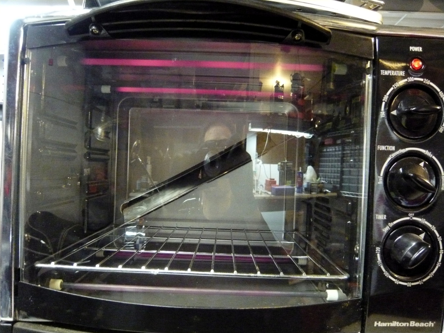
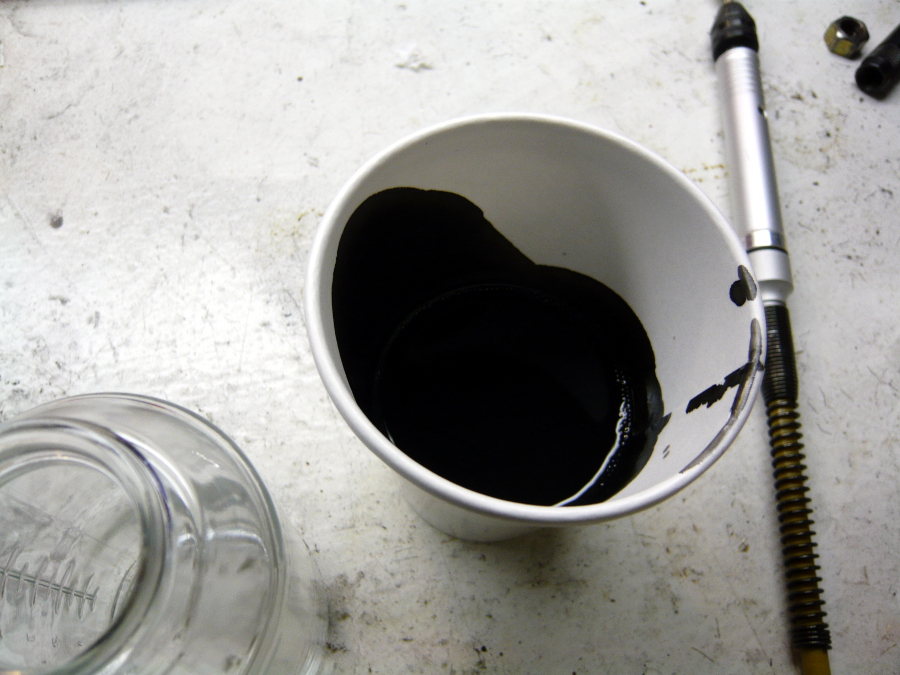
Final product. I had to restart this once or twice due to the initial bad mix and then lousy spray results. The good thing is that acetone wipes it right off so that I could start all over again. It's just out of the oven after curing for an hour so it looked a little mottled still. By morning it was smooth and even.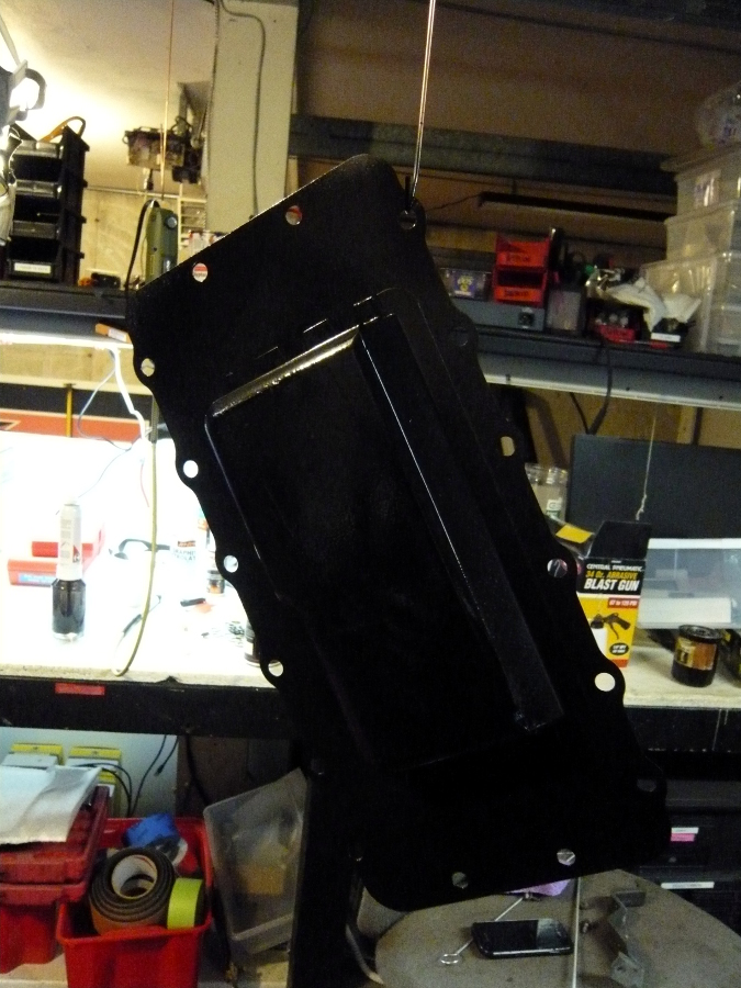
Posted by: r3dplanet Mar 18 2014, 11:26 PM
Good. It will be nice to be less lonely. One major word of advice that I'll address here but expand in the summary is that unless you go with the VW big bore conversion it isn't worth it. If you stick with stock Corvair pistons and cylinders you won't get any more power than a good, hopped up Type-4. But you will get more weight. BUT if you build a 150 or 180 turbo engine, then the Type-4 won't even touch it without a serious dollar investment. It might be a little cheaper depending on where you find your parts and deals. So far I'm in $2800 and all of the parts have been bought. But I still have $1500 worth of machine work to pay for. note also that I'm cutting zero corners and buying the very best parts available. From that perspective it would be very hard to beat this conversion on a bang-for-the-buck point of view. In retrospect, the best possible way to do this, other than the turbo engine, is to find the lowest cost 140 engine that's already in excellent shape and then do the big-bore conversion. You'd be bucks ahead.
Here's a quickie comparison:
Stock 140 Corvair Engine <-> Heavy, only really 110 horsepower. Cheap though. Can rebuild the whole engine for $2000.
Rebuild 140 + 3.1 or 3.0 big bore. This is what I'm doing. More expensive ending up at $4300. Expecting somewhere between 150-180 hp. Less expensive than building up a hot Type-4 1911 or 2056, but not by much. Bolt in conversion. No need to cut up a perfectly good 914 body. Can nickle and dime my way through it. Rebuilding means I'm intimately knowledgeable about my engine and I can really spend time doing things that are too expensive and time wasting for a production machine shop to do - like polishing the case and painting the innards with Glyptal paint, exotic coatings, cryogenic treatment of iron parts, etc.
Corvair 150-180 Turbo. Actual HP numbers apply. But you'll want to rig up an external oil cooler like the water cooled engine conversion folks do. Engines can be found and bought and rebuilt. Sometimes you can just buy a good one outright if it came from a reverse rotation rebuild already. Lots of aftermarket turbo, carburetor, and intake options. The Corvair was the very first production turbocharged car, so hopefully you enjoy retro turbo lag also unless you install a modern turbo. Also, I'm not sure a 901 5-speed has the best ratios for said lag. But maybe. I wish someone like McMark (or you!) would do up a turbo Corvair 914 so we can find out.
All options: say goodbye to valve racket and adjustment. Bleah.
I am watching with a keen eye as I'm seriously considdering the corvair as the power plant for my Q2 homebuilt.-G
Posted by: rsrguy3 Mar 18 2014, 11:46 PM
Well the Q2 is a rutan canard aircraft that was originally built around a continental 0-200 100horse a /c powerplant. I think the weights are comparable. Others are using the corvair successfully in a /c. An injected Turbo would be very interesting in this AP.
Posted by: r3dplanet Mar 18 2014, 11:51 PM
Fantastic. There are scores of aircraft with Corvair engines on the Internet. I read through them and think that perhaps I should get into aircraft one day, but then I think of that magical day back in 1998 when my parachute malfunctioned. My bones still hurt a little. So I'll stick with the far less safe automotive option. If I were doing an Corvair powered aircraft I don't know if I would go with the turbo or just go nuts with multipoint fuel injection. That turbo has to guzzle some fuel. Still, you're obviously a million times more knowledgeable than I so I'd love to hear your thoughts.
Well the Q2 is a rutan canard aircraft that was originally built around a continental 0-200 100horse a /c powerplant. I think the weights are comparable. Others are using the corvair successfully in a /c. An injected Turbo would be very interesting in this AP.
Posted by: rsrguy3 Mar 19 2014, 06:44 AM
I wouldn't go that far. Your hands on right now, and I'm laid up in bed with a back injury. My knowledge is based only on a little bit of personal experience and a lot of research. I am a huge fan of Mega Squirt and itb's, your motor would look and sound insane with high butterfly stacks surrounding that fan shroud! I wouldn't even mess with a Turbo on this AP though, go with a healthy cam optimized for injection, stout compression and start learning about MS.-Guy
Oh, when I was younger I got to see an original Yanko stinger, it was on the corsa body, man was it a serious piece of work. Nader really screwed America on that deal.
Posted by: barefoot Mar 19 2014, 08:14 AM
(*) Fun Fact: The Daniel Fahrenheit temperature scale is based on the lowest temperature he could make in the lab with alcohol and brine, or what he determined would be zero degrees. The high point was based on the human body which he scaled to 100 degrees. By repeatedly poking his extremely patient wife, Wilma, with thermometers he achieved his points and scale. But it turns out that she often had poor health with fevers so it's a bit high. Corrected for non-fever, it's 98.6 degrees. I wish so badly that we used the Metric / Centigrade system in the States, but frankly the goofy system we have is a LOT funnier.
[/quote]
Well at least we don't use British units like stones or fortnights or imperial gallons
I once asked a Rolls Royce engineer why they use imperial gallons/ time unit for gas turbine fuel flow when they could have more precisely used stones per fortnight.
Barefoot
Posted by: Dr Evil Mar 19 2014, 01:51 PM
I really want to build another engine. If anyone is interested, I would be happy to do one for them. It helps that I have found NOT to use the roller rockers from that one supplier mentioned in my other post. Complete shite.
Also, I would be happy to share my CIS intake design. My welding is not great, so you might want to get Mark or Scotty to weld it up, but I can supply the plans.
Posted by: r3dplanet Mar 19 2014, 04:04 PM
I'm all hot over your CIS system. I would LOVE to get your plans to build one up for myself but I have no real fabrication ability and I sold my welding gear off last year.
Coming up soon are my modifications to a set of Ford roller tip rockers. You totally saved me from getting those cheap ass roller rockers from CS, and to go with the full Clark's setup (rockers, girdles, extra deep valve covers, studs) is $1000. I'm not sure I want to spend that on a smidge of extra efficiency. So I'm splitting the difference and going with the Ford roller tip rockers. I'm working on them now and will post the modifications.
Posted by: Dr Evil Mar 19 2014, 05:29 PM
I didnt post here, bit might as well put this information here as well, that after I did a closer inspection all but one of the roller rockers from CS were about to fail and not centered. I checked my geometry while engine on stand, and rechecked, and verified that all the stuff was moving the way it was. I got the wrong parts from him when he first tried to help....check my thread for those details. The owner is not a bad person, per se, he just sells a shitty product. I have since gone back to stock with lash caps due to the valve stem faces getting messed up by the roller rockers failing.
Posted by: gandalf_025 Mar 22 2014, 11:27 AM
I don't know if the reverse rotation cam set ups still use aluminum gears,
but if they do, be sure to pin the gears to the cam..
The stock key setup can fail.
As evidenced by this picture.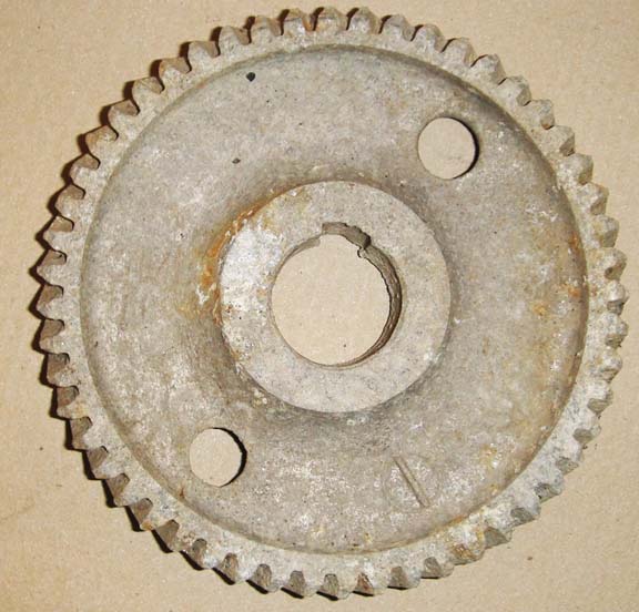
This gear was in a 1965 Turbo Coupe that the owner couldn't get to run
right. He started taking it apart but lost interest.
Look at the size of the keyway. Can't imagine what the timing was like..
This is just a FWIW
Posted by: r3dplanet Mar 22 2014, 11:44 AM
Hey, thanks for chiming in.
My machinist installed my cam gear, which I picked up from Clark's OTTO catalog. It's a modified design from the original. It's made from aluminum and uses a fail-safe steel retainer ring to keep the gear fixed. You have to heat up the gear and freeze the cam, install the gear on the cam, and then lay over the steel retainer ring into a groove on the back of gear with a press and then let it sit there until the temperatures equalizes. I think that the stock cam gears needed to be pinned for exactly the damage you mention. But I don't think you need to do this for the fail-safe style.
Thanks for keeping me in check! I do so appreciate peer review.
I don't know if the reverse rotation cam set ups still use aluminum gears,
but if they do, be sure to pin the gears to the cam..
The stock key setup can fail.
As evidenced by this picture.
This gear was in a 1965 Turbo Coupe that the owner couldn't get to run
right. He started taking it apart but lost interest.
Look at the size of the keyway. Can't imagine what the timing was like..
This is just a FWIW
Posted by: r3dplanet Mar 22 2014, 12:56 PM
Here you go. This shows the newer style cam gear and the steel retaining ring.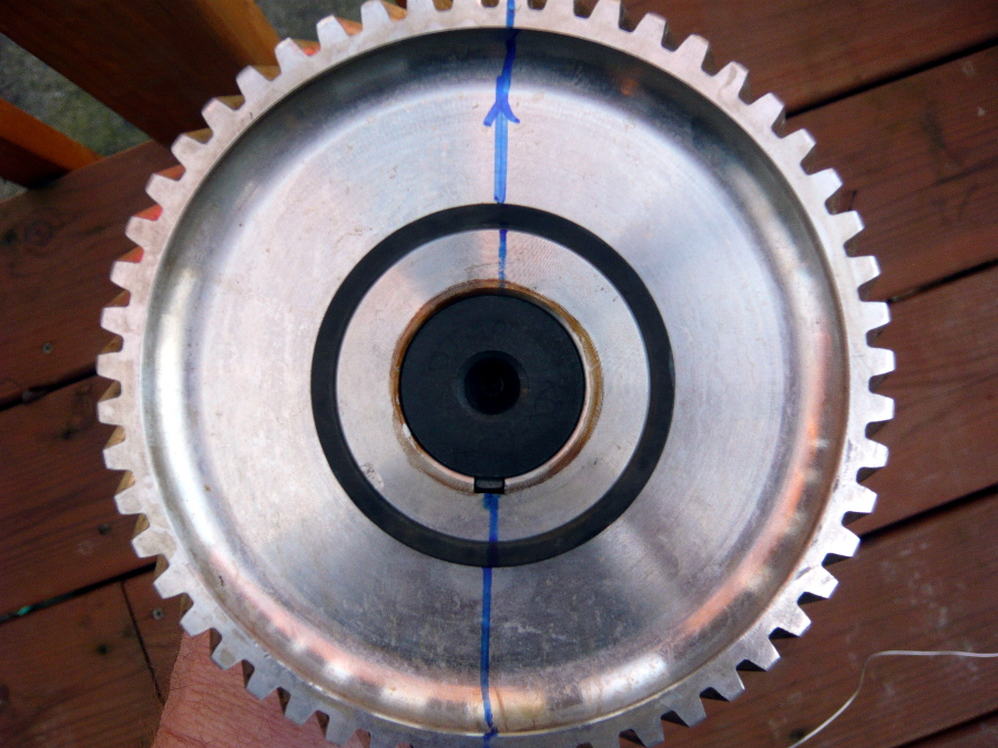
Posted by: gandalf_025 Mar 22 2014, 05:14 PM
Looks like a much better way to attach the gear.
I just checked out the Clarks web site and they
certainly don't give it away though.
I used to drive a Corvair because they were cheaper
to keep running than my 6..
They were great winter cars too.
First time I bought parts from Clarks, he was selling
parts out of his house.
Posted by: r3dplanet May 1 2014, 02:04 PM
So just making a quick report here. I received the rotating assembly back from the machinist after having everything balanced.
The heads, engine case, and connecting rods are off to the specialty machinist in SoCal for the 3.0 conversion. I've decided to go with 92mm thick wall pistons and cylinders (standard 66-74mm stroke) from AA as opposed to 94mm cylinders. This will drop displacement from 3.1 to 3.0 liters, but I could care less about that since this will leave significantly more meat on the heads and produce a longer-lasting engine in theory.
I've also decided to skip the roller rockers and use small block Ford roller-tip rockers instead. It isn't just what happened to Dr. Evil's rollers bought from a lousy vendor, but I've spoken to several Corvair specialty machinists who say that even the high quality roller rockers like to burn through the needle bearings. I'm not down with that. So I'm splitting the difference and going with roller-tip rockers instead. In truth even the bone-stock rockers are perfectly fine. I'll detail the modifications when they return.
One interesting note: you can do this same engine modification and use VW stroker (88mm) cylinders for even more displacement. If you do this, you can machine VW Rabbit or Honda B16A connecting rods. You know, if you wanted to go totally nuts.
The last note is that my machinist had a hell of time machining down the conversion flywheel from Starr Cooke. Cooke doesn't actually do the modification work, he just sells them. But the one I bought sucked. The step was all over the place. Both the top and bottom surfaces were horribly uneven. My machinist called up Cooke to find out what's what but he just played dumb. He was able to surface them down to an acceptable level, but it took him nine hours to do it. In his words, "Marcus, if this was anyone but you I would have thrown this thing in the trash instead of spending all day on it." Yikes. Words of warning.
I'm expecting the turnaround to take quite a number of months, so it might be a while until the next update.
-marcus
Posted by: vw505 Nov 19 2014, 06:55 PM
How is the work going, I have read this post about three times. I am looking for a core motor now.
Posted by: Dr Evil Nov 19 2014, 07:11 PM
Ya howsit goin? I hope your health is holding up
Posted by: r3dplanet Nov 20 2014, 07:41 PM
Peeps,
Apologies. I'm only a month past my stem cell / bone marrow transplant. I'll be down for several more months. Right now I'm spending my time in bed staying unconscious and enjoying a liquid diet in the brief moments that I'm awake. I have the strangest dreams.
Having said that, the project is still go. I'll drop in more as I'm able.
Your pal,
Marcus
Posted by: Mike Bellis Nov 20 2014, 07:43 PM
Peeps,
Apologies. I'm only a month past my stem cell / bone marrow transplant. I'll be down for several more months. Right now I'm spending my time in bed staying unconscious and enjoying a liquid diet in the brief moments that I'm awake. I have the strangest dreams.
Having said that, the project is still go. I'll drop in more as I'm able.
Your pal,
Marcus
Take care of yourself. We can wait.
Posted by: ben*james Nov 20 2014, 08:18 PM
Heel up fast Marcus, you've got work to do!
Posted by: r3dplanet Jan 5 2015, 03:04 AM
The following text is personal. Feel free to skip it and spend your time here instead: http://www.rubiksolve.com
***
I've read that our brains make decisions by utilizing use of only a tiny fraction of our rational frontal lobe parts of the brain, and most of decision making is emotional in nature due to the way we've evolved over time. Add to that that this happens at a purely unconscious level. By the the time you think you've decided on something as good thinking, you're really only rationalizing what your emotional brain has already decided for you several moments prior. It's why diets don't work. Or why we choose mates based on sexual desire. Or why anyone ever bought a Snickers bar. Or an old Porsche.
Because I've been in the dumps for many months now (although I'm up and about and healing rapidly) I've had nothing but time to really reconsider my life, and in what I think is a surprisingly rational way. And it basically sucks. I have bad habits. I spend way more than my means on my many projects, automotive or otherwise. I'm self-employed which is a fancy way of saying that I'll never be able to retire from a job that I increasingly despise. And my recent medical adventures have left me bankrupt, again. As much as possible, I really want my recovered self to do things smarter. Like finding a better job where I can ask for a good pension and six months off at a time for things like heavy chemo and transplants. Maybe ditch my car projects and use the money to buy a dependable car like a Golf TDI or a Ford Fiesta. Eat cabbage soup seven days a week to maintain a reasonable body weight. Buying loafers. Things like this.
During the past ten years I've thought that I was going to die at any moment, so spending ludicrous amounts of money on a 914 or Barracuda or tools or appliances or organic vegetables seemed reasonable. But now that I'm in serious danger of having a future, my thoughts have changed. As I lay on the couch now eating this container of yogurt trying to think about a smarter future I wonder about the wisdom of 914 projects.
My uphill battle of 914 ownership now includes the following:
- I've spent way, way more on this 914 fixer-upper than just buying a good one. The same holds true for my 'Cuda.
- The car has more passenger side long rust that I ever knew, discovered after the car was stripped and painted
- The Corvair machinist has gone missing - along with the engine parts
- I haven't worked in six months and I need to cough up at least $25,000 for more medical bills. Doable over time, but depressing.
- Thinking that a career in crime is an inevitable outcome of my life's path to date, but can't figure out how to profit from third-party arson
I haven't made any major decisions just yet. I'll hold on to the 914 for now and see if my mind changes over the coming months. But it's hard to escape the (apparently rational) thought that maybe this isn't the right path for me any more. Maybe it makes more sense to purge, burn, recycle, or sell all of my 914 stuff and take up a cheap hobby, like repeatedly solving my Rubik's cube.
Thoughts? Input is always welcome.
-marcus
Posted by: bulitt Jan 5 2015, 03:35 AM
Glad to hear you are getting better!!! 
Sometimes removing all these additional projects can alleviate stress in your life. Immediately.
There is the danger though that when you vacate your garage you start thinking about starting up something else 
On the flip side, it is really beneficial to be passionate about something, anything.
Keeps your mind in the game, your body moving, and a purpose to wake up.
There will never be a shortage of old cars, boats, cycles etc. available to work on.
You can always jump back in- when- as you said, you have your health, career, future.
For some people it's the journey, some it's the destination.
Posted by: mgp4591 Jan 5 2015, 04:53 AM
Wow... that's an eye opener. We all (sooner or later) go through some type of self worth examination if we're worth our salt and some are tougher than others. Yours is tough...
I think there's nothing wrong with buying a dependable car based on Rubiks Cube calculations of probability, but if we don't pursue what fires passion in us we're missing something. If working on these machines is what you love, there's intrinsic value in that. If running your business is getting mundane, think of what drove you to do it in the first place. If it's still worth it, do it. But then, there's nothing wrong with a good 401K...
Just my 2 cents... best wishes Marcus.
Posted by: rhodyguy Jan 5 2015, 12:16 PM
HEY! You should be able to get some assistance on the med bills. File medical bankruptcy. They can't take what you don't have. Drug manufacturers have all kinds of programs. My cousin, stage 3-4, iirc, matastic prostate cancer, gets assistance on the 'life extending' magic drugs. They retail for roughly $9k a month. Plus another monthly injection that is $6k per. Plus the usual tamulosin and finesteride (sp). Had my cousin not relocated to washington he would be dead.
Posted by: bandjoey Jan 5 2015, 12:31 PM
Our hope for the best in job, finances,and great health. There's always a teener seat to ride in somewhere.
Hopefully someone local can go by and help find your motor parts from the crook.
Posted by: JRust Jan 5 2015, 05:19 PM
I know your health has been an issue for a long time Marcus. I don't think a Purge of projects is a bad way to go at all. What you get out of the projects might be more depressing though. I know the Cuda is probably the most ready & worth the most. Although I'm sure your bike if it was up for sale would go quick too. I don't know that market but am sure it would pull good money.
The 914 is always a tough call to get rid of. I know you have put a lot into it. When I was up helping you pull the motor. I was shocked & felt bad at the passenger longitude. I know you had paid for a good paint job. So it really sucked to see that. The PO floor pans were a surprise too. First setup I had seen that way. I think you would be money ahead getting a more solid chassis than fixing that one. Always brutal to make that call. Especially when you have so much invested. Not only monetarily but emotionally & physically. I went through something similar recently with some trucks I made the mistake of buying. Finally just cut my losses & got rid of them all. I lost affair amount of money overall with them. It was still a relief to have it all gone that the money wasn't as big a deal. Was just glad to be done with them
I'm happy to help in any way that I can. I'm also more than happy to take you for a spin in my 914 when the weather clears up .
Posted by: arkitect Jan 5 2015, 08:16 PM
Marcus,
I hope things turn around for you. You are one heck of a meticulous engine builder.
I don't know that much about the corvair engine, just seen a rerun of Chasing Classic Cars about the Fitch Phoenix that John Fitch used a corvair powerplant. Pretty cool history, too bad with the timing of Ralph Nader.
Reality tends to get in the way of our dreams, but what would life be without them?
Dave
Posted by: SirAndy Jan 5 2015, 09:08 PM
Since i have nothing technical to add here, how about something environmental:
Just one liter of oil in the soil can contaminate 1 million liters of ground water.

PS: I hope this all works out for you.

Posted by: SirAndy Jan 5 2015, 09:15 PM
In that case, you *need* this:
http://toyland.gizmodo.com/it-took-this-guy-over-7-hours-to-solve-the-worlds-harde-1676955636
https://www.youtube.com/watch?v=Q4BrzJbtRZg
![popcorn[1].gif](style_emoticons/default/popcorn[1].gif)
Posted by: DarkMonohue Jan 5 2015, 09:39 PM
Posted by: r3dplanet Jan 5 2015, 09:52 PM
Peeps, thanks for the well wishes. As yet I'm still undecided about the long-term viability of all of this. My mind is in much better shape than my body so I stew and think and stew and think. Mostly I think that what I need is a Swedish bride and a suitcase full of money.
I spent a little time in the garage today and I forgot that I had assembled all of the parts necessary to upgrade my 1.7 liter engine to a 1911cc. That gives me something to work on when I'm able (and when the weather warms up). I'll work on that and make further attempts to get in contact with the missing machinist as time passes.
I've still got the greatest enthusiasm and confidence in the mission.
-m.
Posted by: r3dplanet Jan 5 2015, 09:56 PM
Along with the Plymouth Barracuda. Sigh. Something like twelve Mustangs sold for every one Barracuda.
Although technically the fist generation of Mustangs were re-bodied '60-'62 Falcons. But you're right, the Corvair body was right out of the 50s and looked too vintage.
Posted by: r3dplanet Jan 5 2015, 10:09 PM
Dave, that's good info.
My view has always been that Nader actually was right to point out the things he pointed out, and much of it was true for many of the cars of that era and their appalling lack of safety. Eventually the government investigated his claims and found them to be no worse than other cars of the time, and many of the claims were debunked. But it all happened right as most manufacturers starting paying attention to safety anyway. And as DarkMonohue says, releasing new models of much more modern cars like the Mustang more befitting of the 1960s took the market.
In effect, Nader had an effect on sales but wasn't the straw man that he was made to be. My ears ache from all of the "Nader this" and "Nader that" bogeyman stuff you hear when dealing with the old Corvair gang. After 1964 all his complaints were rectified in the new model of Corvair in any event. I liken this to the Karmann Ghia - designed in the 1950s but looked too old in the late 60s. Hence it's replacement, the 914.
But from my small standpoint, and after reading Nader's book, nobody ever said anything bad about the engines. And that's the only part I care about.
Marcus,
I hope things turn around for you. You are one heck of a meticulous engine builder.
I don't know that much about the corvair engine, just seen a rerun of Chasing Classic Cars about the Fitch Phoenix that John Fitch used a corvair powerplant. Pretty cool history, too bad with the timing of Ralph Nader.
Reality tends to get in the way of our dreams, but what would life be without them?
Dave
Posted by: messix Jan 5 2015, 10:12 PM
new career?
become a politician !
you cant beat the work hours and the medical and pension.
and !!! no matter how bad you fuck it all up you still keep your job.... uh oh I just went there..... 
Posted by: r3dplanet Jan 5 2015, 10:15 PM
Um, no thanks. I used to work in DC for the State Department. Political appointees were the worst. But you're right - it would be nice to have the job perks. But from my point of view every worker should have the same benefits those bastards do.
new career?
become a politician !
you cant beat the work hours and the medical and pension.
and !!! no matter how bad you fuck it all up you still keep your job.... uh oh I just went there.....
Posted by: messix Jan 5 2015, 10:16 PM
and don't forget to enjoy same of the simple indulgences, like pine state biscuits and some salt and straw!
Posted by: DarkMonohue Jan 5 2015, 10:20 PM
Although technically the fist generation of Mustangs were re-bodied '60-'62 Falcons. But you're right, the Corvair body was right out of the 50s and looked too vintage.
I don't think the poor little Baccaruda had nearly the options list the Ford did, either. Pity.
Anyway, sorry for the derailment. I came here as much for the Corvair content
 as the 914 stuff.
 Posted by: mgp4591 Jan 5 2015, 10:28 PM
Just a quick question as I'm clueless- what year 'Cuda so I can drool some more?!
Posted by: Johnart May 14 2015, 05:48 PM
I have 3 914's.....one daily driver and 2 parts cars.....about a year ago I bought a Corvair (reversed cam) with the idea I would someday put it into my "72 slope nose....just found this string today and am in awe of all of the expertise and experience......really looking forward to this project now.......I plan to replace the jugs with 94mm VW......3.1L sounds good.
Thanks all
Posted by: r3dplanet May 15 2015, 03:50 PM
Johart,
I think you would be better off going for 3.0 liters of displacement instead of 3.1. The only difference is that the 3.0 liter engines will use 92mm pistons and cylinders instead of 94mm. I went with AA 92mm cylinders because the barrel thickness was excellent; much thicker than the 94mm cylinders I found.
My engine case and cylinders have been in the hands of a machine shop in SoCal for a year and a half now, and I wonder if I'll ever see them again.
Hopefully.
-marcus
Posted by: Johnart May 19 2015, 10:44 PM
Johart,
I think you would be better off going for 3.0 liters of displacement instead of 3.1. The only difference is that the 3.0 liter engines will use 94mm pistons and cylinders instead of 96mm. I went with AA 94mm cylinders because the barrel thickness was excellent; much thicker than the 96mm cylinders I found.
My engine case and cylinders have been in the hands of a machine shop in SoCal for a year and a half now, and I wonder if I'll ever see it again.
Hopefully.
-marcus
Thanks Marcus.....I think you are right......hope you get yours in and on the road soon.....no FUN waiting.
Posted by: r3dplanet Jun 10 2015, 04:02 PM
Good news, everyone.
In the past week the engine case halves have been returned from the machinist. However, he has yet to return the pistons and cylinders. I have high hopes that those parts will also soon return.
In other good news, Tom Knoblauch has produced a pair of beautiful aluminum intakes with custom tapers to perfectly fit the Weber 44 carbs. I'm thrilled with them.
Strangely, I'm now in the position of building two motors simultaneously: the 1911 and this Corvair engine. I suppose I need to find a roller with flares for one of them...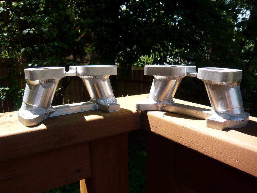
Posted by: vw505 Aug 16 2015, 05:31 PM
Nice, I've spoken to Tom a few times and hope to have him do my heads.
Posted by: r3dplanet Aug 17 2015, 02:17 AM
Indeed. I have nothing but praise for Tom. But the machinist who stole my engine parts, not so much.
Posted by: r3dplanet Feb 4 2017, 11:59 PM
People,
I'm pleased to announce that the project is back in motion.
It took a very long time to recover from the transplant and I still have complications. But I've been spending my time in night school in a machining program, so that's fun and gives me access to large, fun machines.
I've re-purchased all of the parts that I lost and they're on their way to the respective machinists for modification. After those return, it's fun assembly time.
That is all.
marcus out
Posted by: KELTY360 Feb 5 2017, 12:02 AM
Glad to hear you're back.
Posted by: JRust Feb 5 2017, 12:10 AM
Good to hear things are improving health wise Marcus. Been a while & good to see you back posting
Posted by: raynekat Feb 5 2017, 03:34 AM
Marcus:
I'm out here in Boring, so I could always lend you a hand (muscle wise) if you need that from time to time. Fun reading about the Corvair engine project. Good luck with your project. You seem like quite the "mad scientist"? In a good way.
Posted by: Dr Evil Feb 5 2017, 08:09 AM
Kick ass!
Posted by: r3dplanet Feb 5 2017, 01:57 PM
Fantastic. Always great to have local friends. And yes, the "mad scientist" type certainly applies. I'm burdened with way too many interests and hobbies. But weirdly, all of them are expensive. Why couldn't I settle for crosswords instead?
It's great to hear from the old gang. I'm glad you guys are all still here.
*
Some serendipity these past few days:
First, Tom Knobluach is wanting to do the exactly same 92mm VW Type 1 cylinder conversion, so he's doing the work for both of us simultaneously. So I bought all the parts and he's doing the machining. Good. I also did some measuring and discovered that on my heads the chamber opening is still the stock Corvair diameter at 96mm. The outer diameter of 92mm VW cylinders is 101.10mm, so Tom is also going to flycut them to the correct size. That's better since he'll have the cylinder in hand to measure. I've seen the slop between these at a build parties off by 2mm. Yikes.
Second, another machinist is modifying the case halves to increase the oil passage sizes. The stock passages are a joke and he's got all the rigging to do it right. Weirdly, he has a very similar cancer to mine and he's been out for a while also. So I picked up a new friend.
I think it worked out better having to do this part of the operation again after pausing a few years. But what a strange path to get here. I hate to use the term but I think my "qi" is in whack.
Anyway, all the parts are shipped off. This week I'm getting the crankshaft nitrided. The crank has already been cryo'd, ground, and polished. It's not a factory nitrided crank like I would have liked, but it's cheap do to and this way the nitriding will not have lost any depth from grinding.
-m.
Marcus:
I'm out here in Boring, so I could always lend you a hand (muscle wise) if you need that from time to time. Fun reading about the Corvair engine project. Good luck with your project. You seem like quite the "mad scientist"? In a good way.
Posted by: r3dplanet Feb 5 2017, 01:59 PM
Hey, what's the lastest on your Corvair powered bus? Any updates? The last I saw you were sorting out the CIS system.
Kick ass!
Posted by: r3dplanet May 28 2017, 04:40 PM
'Twas a pleasant summer's eve so I took the case halves outside for a refreshing douche. This is a makeshift parts cleaner assembled from an oil pan, aquarium pump, and an Oxford comma. Purple Simple Green is used to remove the last of the machining swarf and bits. I wish they would name it "Complicated Purple."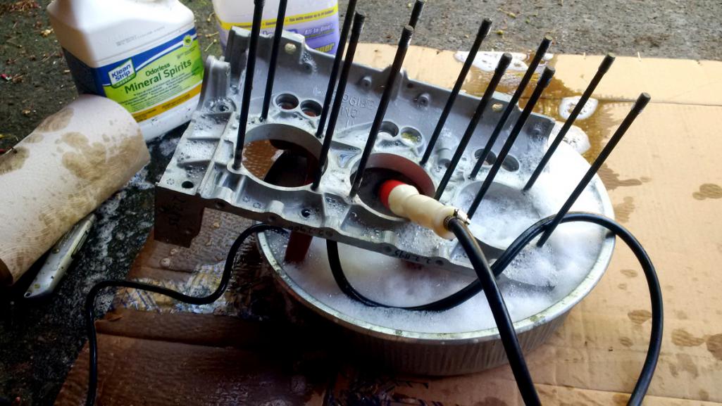
I received the case halves from Tom Stark a while back for some modification and he did a stellar job. A common problem with the cases is that the depth of the oil passages for the main bearings are too shallow. Indeed, some are so shallow that they're not a passage at all. Add to that that the passages are sometimes misaligned with the bearing holes, creating a blockage.
Enter Tom Stark, who has a setup where he uses a mill to widen and deepen the passages. It's a huge improvement for more oil volume. Frankly I don't know how the unmodified passages allowed any oil through them in the first place. Often when I work on this project I repeat the mantra with an inward voice, "GM just did not care."
Here you can see the detail of the enlarged oil passage. I'm sorry that I don't have a "before" photo handy. But trust me, the depth was all over the place and it blocked the original bearing oil holes by over half.
Another modification is enlarge the oil hole itself that leads to the main oil gallery.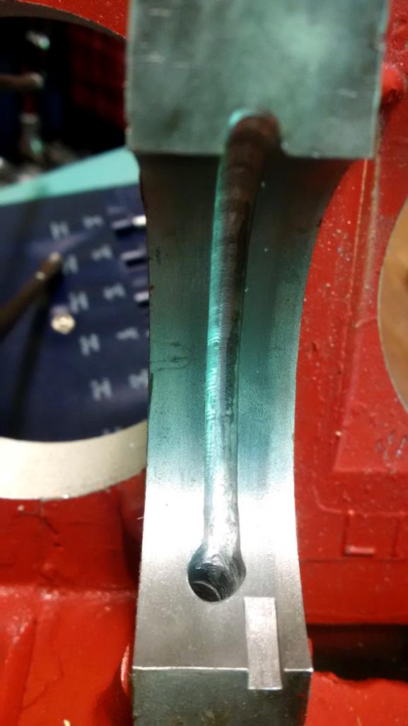
Before I installed the bearings I took some measurements on the inside crank registers. Tom did also but I wouldn't be doing my job if I didn't double check. Besides, this is really all about having fun with arithmetic anyway.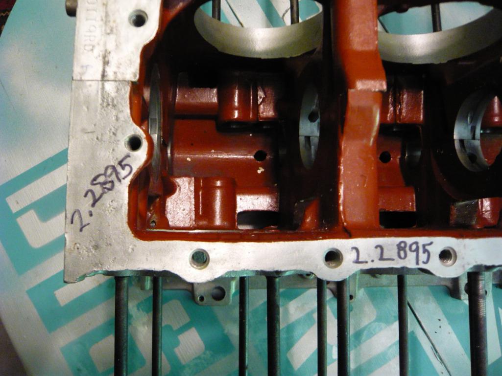
More importantly, I also started the blueprinting process so I took careful measurements of the mains along the crankshaft.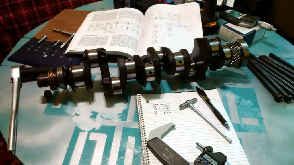
Posted by: r3dplanet May 28 2017, 05:13 PM
Time to check the bearing clearance and oil passage holes.
The bearings themselves are Clevite 77. For mains #2 and #3 the bearings are the same. But somewhere along the way GM changed the size for #4. Bob Helt says this has to do with a lumpy idle problem encountered before the change. Observe: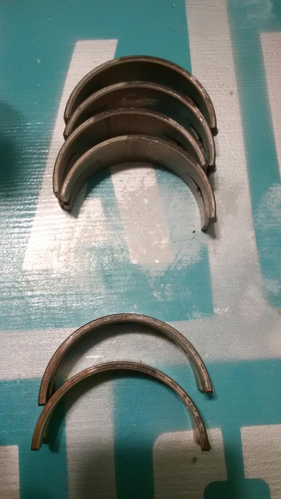
Here you can see how well the diameter of the oil hole in the bearing meets the enlarged oil passage. Helloooo oil volume: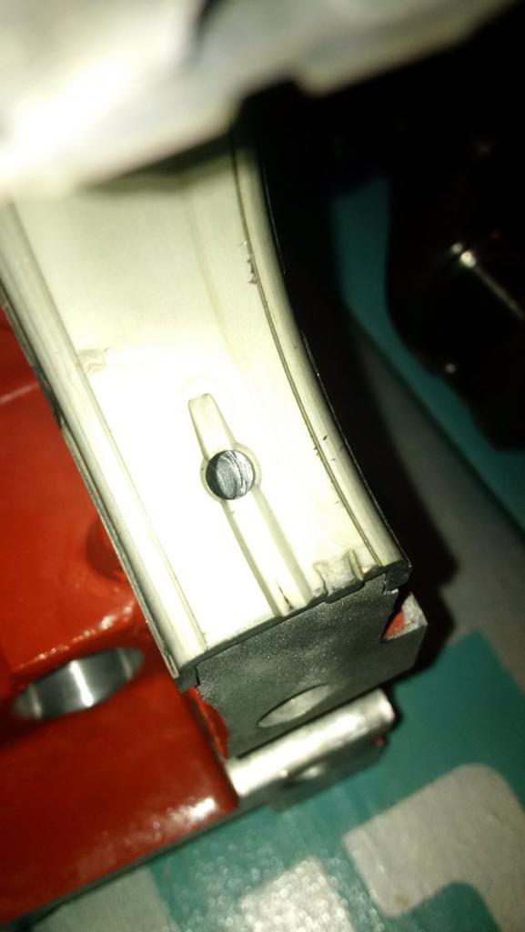
Here are the bearings installed in the case halves: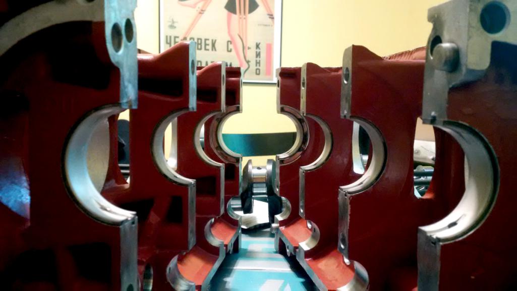
I torqued the case halves back together to measure the inner diameter of the bearings. And, unhappily, they all measured about 0.010" too large. Bummer. This troubled me for a while because way way back I had a machinist check out the case, bearings, and crankshaft to make sure they were all in spec. So where did this 0.010" difference come from?
Then I finally remembered. I have two crankshafts and completely forgot that I had two cranks because (a) I'm chemo-brained and (b) it's been a long, long time.
I forgot that initially I had the original crank measured, magnafluxed, ground, and polished to 0.010" undersize. Then I sent it off to be cryogenically treated. But over the years enough doubt was cast on the cryo process that I replaced it with a factory nitrided crank. It's important to understand that the better Corvair cranks were nitrided from the factory, but my original crank was not as discussed in a previous post. So eventually I bought a NOS nitrided crank thinking it was the better surface hardening method over cryo.
But the fact is that I really do not know. It's been debated so much that I honestly don't know which would better fit my needs, which mainly have to do with longevity. But now I have two great cranks with absolutely no way of truly knowing which is better.
It's apples and oranges most likely. Nitriding is a suface hardening process and cryo is a process to remove any internal stress and improve it's overall toughness. Oy. Anyway, here they are: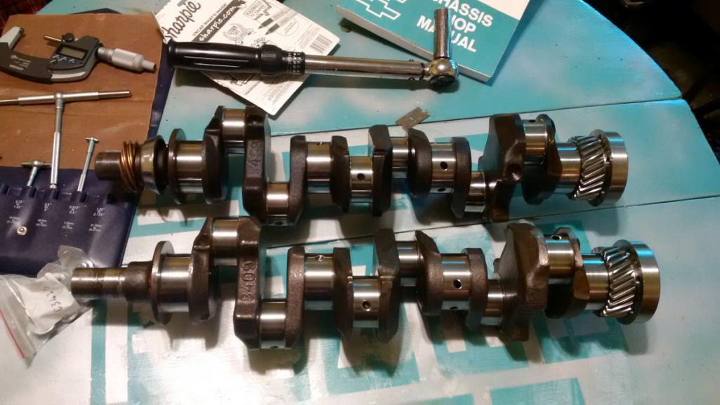
So my choice is to either use the cryo'd crankshaft and use the bearings I already have, or use the nitrided crank and order two new sets of bearings. One pisser is that you cannot buy individual bearings. You have to buy a complete set. And it turns out the big shell bearing for main #1 is not out 0.010" but 0.0065". So if I buy new bearings I have to buy two whole sets to get the sizes that I need. Super!
Either way I have one great crankshaft for sale. I'm open to which way I should go if anyone knowledgeable about metallurgy cares to opine.
Cheers.
Posted by: r3dplanet May 29 2017, 11:13 PM
Today I spent some time getting the rest of the measurements for the bottom end.
The camshaft got the plastigauge treatment and it's dead nuts 0.002" clearance across the board. The service manual says it needs to be between 0.0015" to 0.0035", so that makes me happy.
I measured the ID of the big ends of the piston rods and that's where this gets interesting. And by interesting I mean super boring. With the bearings I have in hand they're a perfect fit for the rod journals which measures 0.010" undersize from standard. No problem there since one of my two cranks measures 0.010" undersize...
.... the crogenically treated one. So that's the answer to above soliloquy. If I stay with the cryo'd crankshaft, then I can keep my main bearings, rods, and rod bearings. The rods have already been machined to fit the VW piston pins. That's a pile of money and time I don't want to spend in replacing stuff. Plus, the measurements for the crank and rods have been beautiful so far. I sort of hate to throw all that out since it all fits together so sweetly.
Plus, science. It occurred to me today maybe instead of looking for an answer to cryo vs nitriding I should instead pop in the cryo'd crankshaft and see what happens. At worst it will simply wear down faster. It's not like it's just going to split apart. So one day when one of you owns this car and takes the engine apart, do us all a favor and measure the wear along the journals and note the mileage. That way we can all know. Of course it isn't great science since I'm not building an identical engine using the nitrided crank, but there's enough data out there to get a comparison.
Empiricism or bias confirmation? You decide.
If you in the future are the owner of this car and have disassembled the engine then you'll want to know that the main journals measure basically 2.0985" and the rod journals more or less at 1.9327". Good luck, time traveler!
Posted by: r3dplanet Jun 25 2017, 02:11 PM
So I damn near ruined my case halves.
There are eight (8x) case studs that clamp the case halves together, but they are a slop fit and allow the halves to slide around a little at higher temps and revs. So for a long time ARP case studs have been available that have a larger diameter in order to create an interference fit. Great.
The trouble is that outfits like Clark's or others-that-shall-not-be-named will sell or rent a reamer that provides the exact diameter necessary to make the correct fit. But Clark's doesn't have them any more and other vendors failed to even mail me back and didn't answer the phone.
Since I couldn't obtain the "special" reamer, I had to try something else.
My first plan was to get an adjustable reamer, which I hate. I've never had good luck with them. I ended up buying a few of them before I found one that was even marginal quality. Even with my measuring stand it's hard to set the tool to exactly the right size. Every time the tool is set and tightened, it threw out my measurement. I drilled the first hole to a depth of about 5mm and then measured the new bore.. and it was way WAY out of size. Not a big deal since there was so much meat left, but I wasn't happy. So I spent a few hours with a piece of scrap aluminum sneaking up on the bore size, but it left a positively brutal finish.
I didn't think the adjustable reamer would last for all sixteen holes and the finish was unacceptable, so I went to Plan B.
The dimension in question is the outer diameter of the case studs at the center bulge, measuring 15/32" (0.4688"). I ended up using a 29/64" drill bit (0.4531") and then using the reamer. It's the best match I could find but hand reaming .016" sucks, especially when it's sixteen holes. 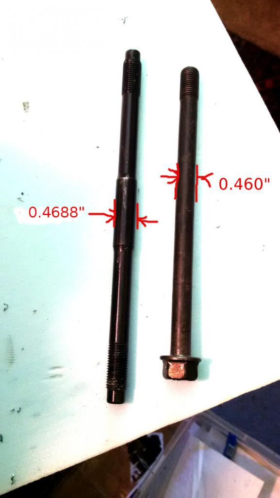
On the right side of the engine the bore is increased all the way through. On the left side of the engine the bore is only increased about an inch to give the studs someplace to seat.
I'm not super happy about the outcome, but it will work and the fit is quite good. But I worry about what might happen if any of the mating bores are a little off. It makes for white knuckles.
Anyway, all of the prep is now done. Now I need to thoroughly clean out the engine halves again and it's time for assembly. FINALLY. 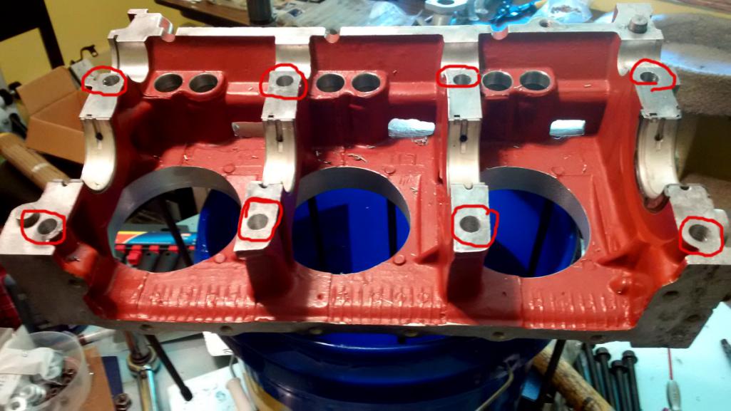
Posted by: r3dplanet Jun 25 2017, 06:54 PM
Alright...
It's 102 degrees (39c) outside so I hosed myself down with the garden hose and pulled out my bucket-based parts washer. I very thoroughly and very carefully washed out both case halves, blasted them with clean water, and then with compressed air and set them out to dry. No problem on a horrible day like this.
So let's start the assembly.
Before cleaning it, I pulled and numbered each of the main bearings. After cleaning the cases I cleaned the bearings with mineral spirits, popped them into place, and smeared on some good synthetic assembly lube.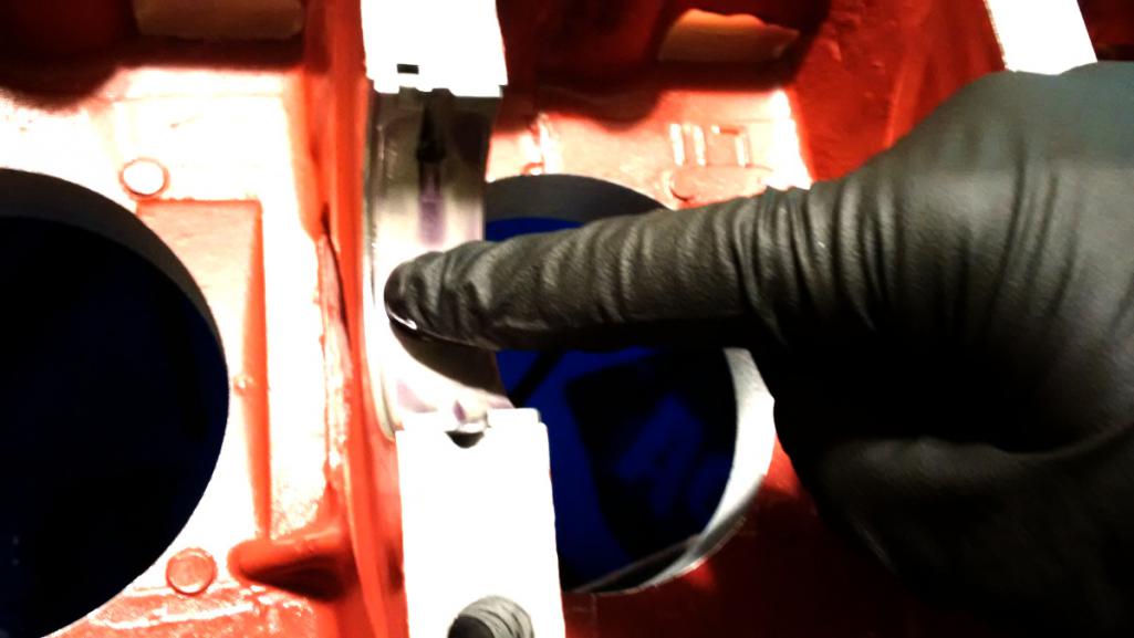
I cleaned the crank with the nastiest residue-free cleaner I had (Berkebile 2+2) and made very sure it was as clean as I could get it and that no remnants of plastigauge were left behind. The crank popped into place and rotates as smooth as can be.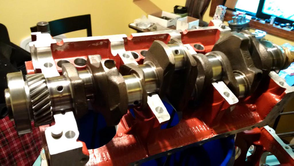
Here is the timing mark on the crank. It's remarkably small and barely looks like it was deliberately placed. I drew some reference lines with a marker to verify it's position in relation to the mark on the camshaft.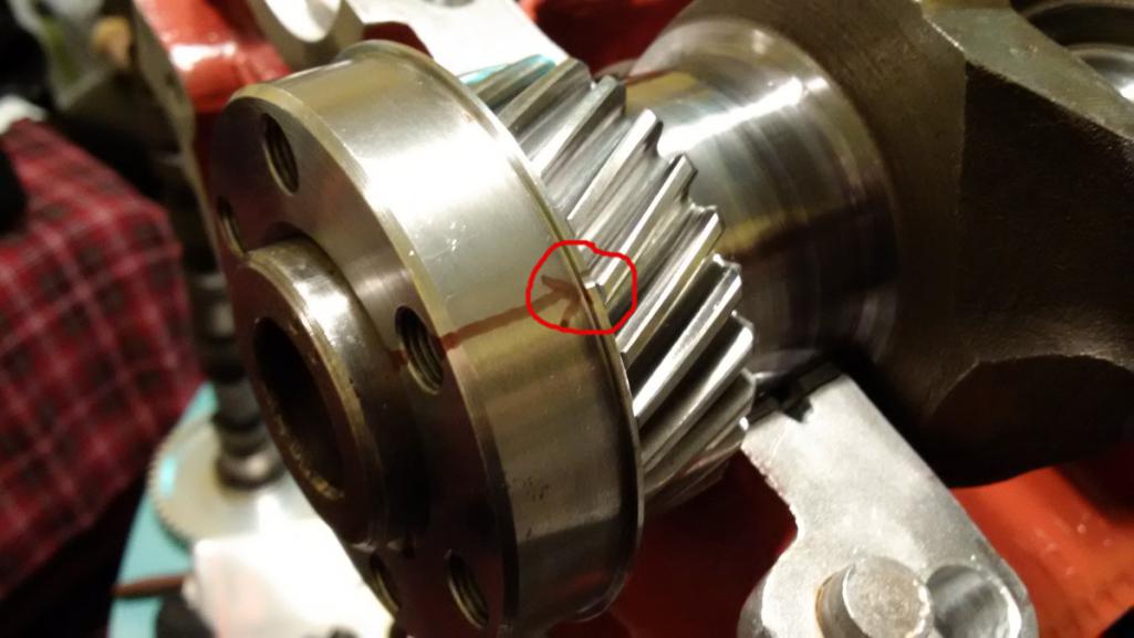
I couldn't photograph and install the cam at the same time, but it's the same procedure as an air cooled VW. Line up the marks and walk the cam into it's home. In this photo you can look into the bolt hole of the crank gear and see that my sharpie-based cam and crank marks line up correctly.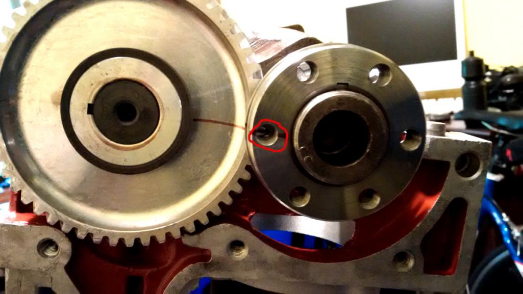
Here they are together in the case. 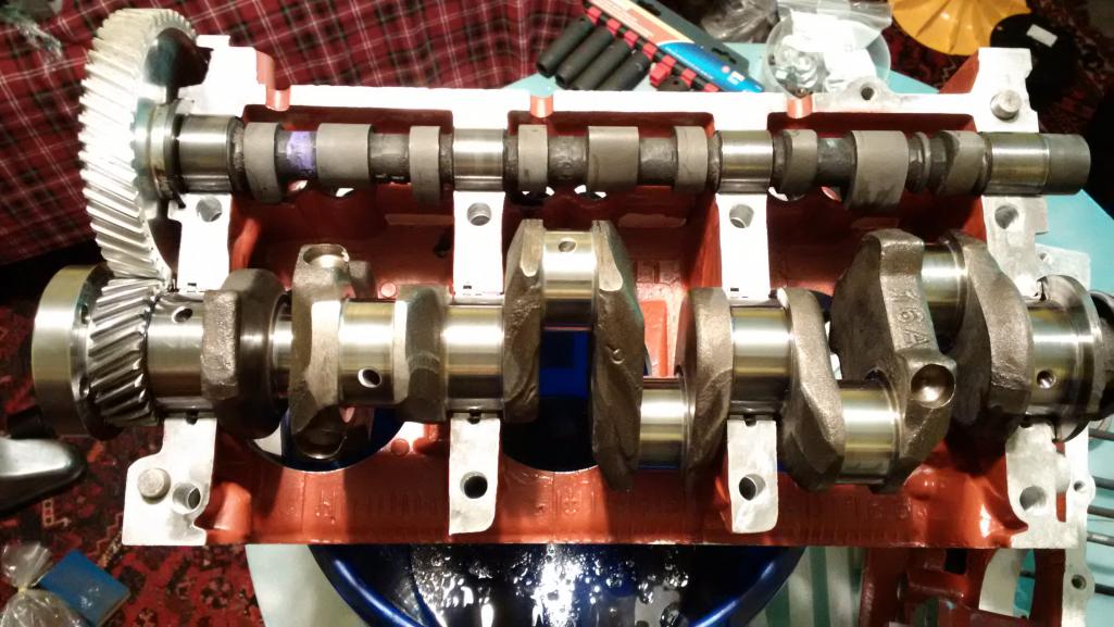
And then I clean, install, and lube the opposite main bearings and camshaft and mate the other case half. I bolted the case halves together with the OLD case bolts because I want to make sure it continues to freely spin as I torque down the nuts. I'll have to separate them once last time to smear on some Yamabond or or something. But first I want to degree the cam and then verify end play.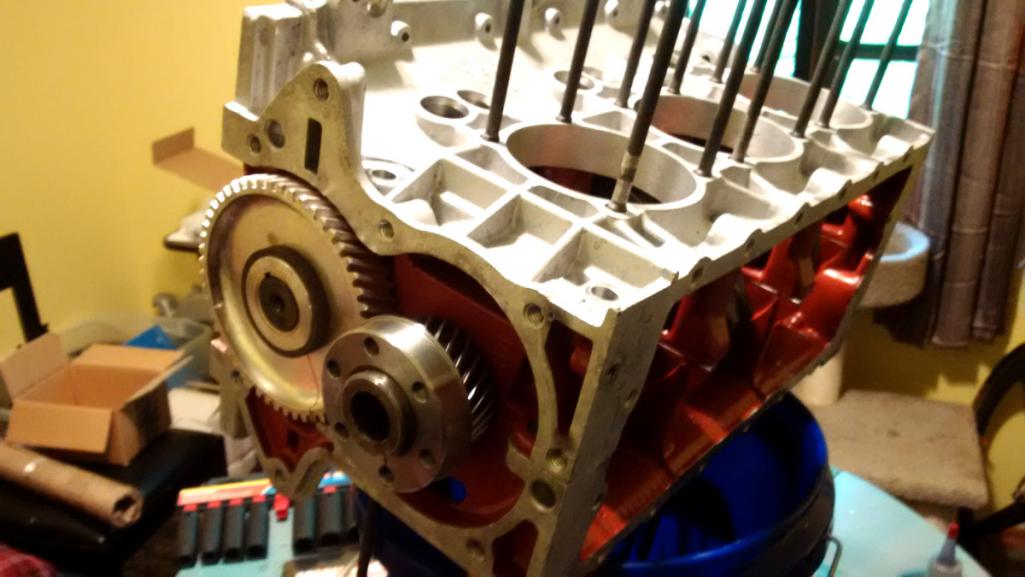
The factory service manual says to measure crankshaft end play and make sure it's between .002-.006". You can see here that mine is at .004". That's a relief.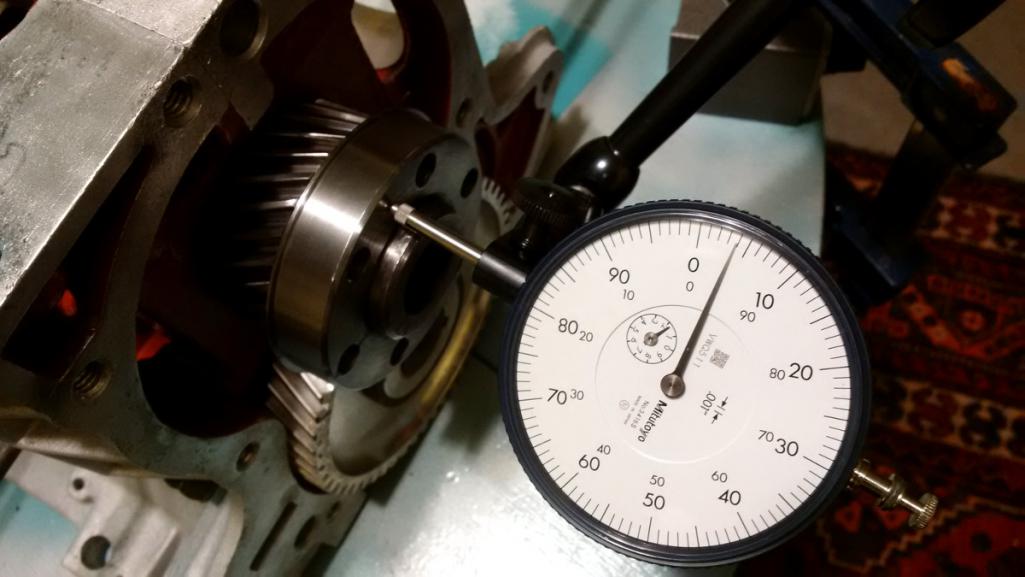
The next step is to degree the cam. It's next to impossible for this particular cam to be that far out of whack, and if it is I'll need to use an offset Woodruff key, which means pulling it all apart again. I hope that doesn't happen. Mostly I just want to verify the cam/crank timing. In the meantime I think I need to buy an adapter so I can connect a degree wheel.
More soon.
Posted by: r3dplanet Jul 2 2017, 03:14 AM
Sooooooo let's degree this thing and make sure I didn't install the camshaft off by a tooth or something stupid. I like sanity checks. Here's the situation as of a few hours ago. I installed rings onto one of the pistons (more on this later) and then the piston into cylinder #1. Then I made a high quality genuine Red Planet Industries piston stop.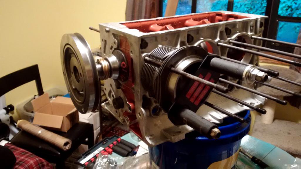
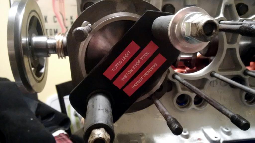
I've been following a Corvair aircraft engine build by a cat named Mark Langford, and he has a good write up on degree-ing the cam. He even provides a nice template to use with the existing crank pulley. Here's the link:
http://www.n56ml.com/corvair/degree_cam.html
The idea is to use the piston stop to find actual TDC for this engine. Install the high quality piston stop, rotate the engine one way and until it stops and use the centerline of the case to mark the pulley. Then rotate the other way until it stops and make another mark. In between both marks is actual TDC. (Full disclosure, I also removed the high quality piston stop and rigged up a dial micrometer).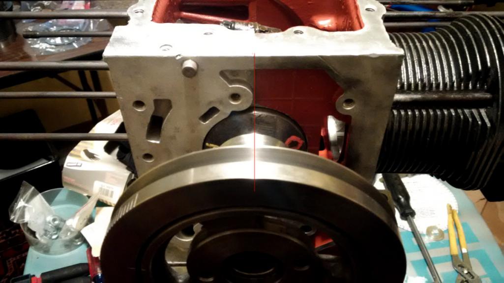
It turns out that it's very nearly dead nuts accurate. I was more than surprised.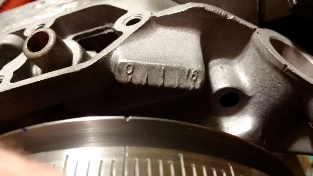
Here's Mark Langford's template taped to the pulley. I failed to get any clear photos of the dial indicator gauge on the intake and exhaust lifters. Oh well. This is already super boring for everyone but me. 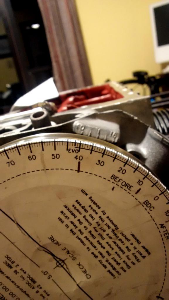
So finally I ended up with the following numbers. Basically there's no place where my cam deviates by more than one degree, so I'm very very happy indeed.
Intake at .005"
Card Me
Open 25 24
Close 65 64
Intake at .050"
Card Me
Open 1 2
Close 35 34
Exhaust at .005"
Card Me
Open 72 72
Close 32 33
Exhaust at .050"
Card Me
Open 42 42
Close 8 7
Huzzah!
Posted by: PatrickB Jul 2 2017, 05:36 AM
Just a quick question as I'm clueless- what year 'Cuda so I can drool some more?!
That was a '65 I saw in a pic back there, prefer the '66 myself.
Posted by: Porschef Jul 2 2017, 06:34 AM
'Tain't boring a'tall, not that I know exactly what you're doing...
Impressive nonetheless. As well as your constitution.
Posted by: r3dplanet Jul 2 2017, 12:12 PM
Oh right, yes my Barracuda is a '65. It's virtually all new underneath. New 360ci engine, gearbox, disc brakes, larger clutch / bell housing, driveline, 8-3/4" rear end, new interior, re-upholstered everything, hydroboost p/s and p/b, hydraulic clutch, headers, a million other things. I found a painter in town that I really like so I'm thinking about finally getting it painted. Or maybe I'll sell it. The Barracuda is a gentleman's cruiser, not a hot rod. A true GT car. I'll decide what to do with it and the end of the year. All I do is work on it. I almost never drive it. But that's starting to change finally. But I might sell it because I have yet another project - a Beetle. Long story. More on that later.
The '66 and '65 are nearly the same car. The '66 had some cosmetic differences and a slightly different gauge cluster. And some little differences in the 273ci engine. Both are very cool though. I hardly ever see them around any more.
Seriously - after I sell off all this stuff I'm dedicating my life to cheap hobbies.
Just a quick question as I'm clueless- what year 'Cuda so I can drool some more?!
That was a '65 I saw in a pic back there, prefer the '66 myself.
Posted by: barefoot Jul 2 2017, 02:34 PM
[quote name='r3dplanet' date='Jul 2 2017, 05:14 AM' post='2502276']
Sooooooo let's degree this thing and make sure I didn't install the camshaft off by a tooth or something stupid. I like sanity checks. Here's the situation as of a few hours ago. I installed rings onto one of the pistons (more on this later) and then the piston into cylinder #1. Then I made a high quality genuine Red Planet Industries piston stop.
I did essentially the same thing using a spark plug modified by knocking out the ceramic & ground electrode and welding in a longer stub that would contact the piston somewhat before TDC. rotating to this stop one way, then the other nailed TDC exactly
Posted by: r3dplanet Jul 17 2017, 09:02 PM
That would work great. There's always another way. But in this case I wasn't prepared to install a cylinder head yet, but I'll use your idea when I get to that point for quality control. Thanks!
I did essentially the same thing using a spark plug modified by knocking out the ceramic & ground electrode and welding in a longer stub that would contact the piston somewhat before TDC. rotating to this stop one way, then the other nailed TDC exactly
Posted by: r3dplanet Jul 17 2017, 09:28 PM
This seems like a good moment for an update. Lots of work happening lately.
First, I finally got the case halves to bolt up to spec with the ARP case studs. Some deep thoughts from me to you on this subject:
1. Have a machine shop do the reaming to enlarge the stud holes. I ended up with a mess after my adventure with the adjustable reamer. Don't use one! Eventually I used a 15/32" spiral reamer to clean up the job but I still had to make some adjustments and white-knuckled my way through it. If the alignment is slightly off you'll never get the case halves to mate and the crankshaft will freeze.
2. I had to ditch my Craftsman torque wrench. It was off by 10lbs and it took me forever to realize it. Plus, it's hard to situate the torque wrench in such a way that the head of the wrench doesn't apply pressure to one of the inside head studs. That throws off the torque value quite a lot.
3. Or just don't do it and keep the stock case studs.
4. Tom Knoblauch wisely states that if you do this, just do the inner four studs, not all eight. The outer areas of the case have alignment pins and don't need the studs. Save yourself the headache of doing all eight.
Next, it was time to attach the oil pickup and pan. Both are from Otto Parts, a cool aftermarket go-fast Corvair parts supplier that is part of Clark's Corvair Parts. This engine will get a few Otto parts: oil pan, valve covers, oil pickup, case studs, all sorts of things.
After bolting the engine halves together, I spent some time with a surfacing stone to make sure the oil pan mating surface was flat as possible. This lets me use one of my favorite tools: a huge 1/2" thick tapered glass plate. It's great for surface measurements, flatness gauging, motorcycle fork plane comparison, with sandpaper as a surfacer, a million and one uses. After a little stone work the mating surface is flat, flat, flat. Mostly just little burrs or imperfections - nothing serious.
Here's the oil pan: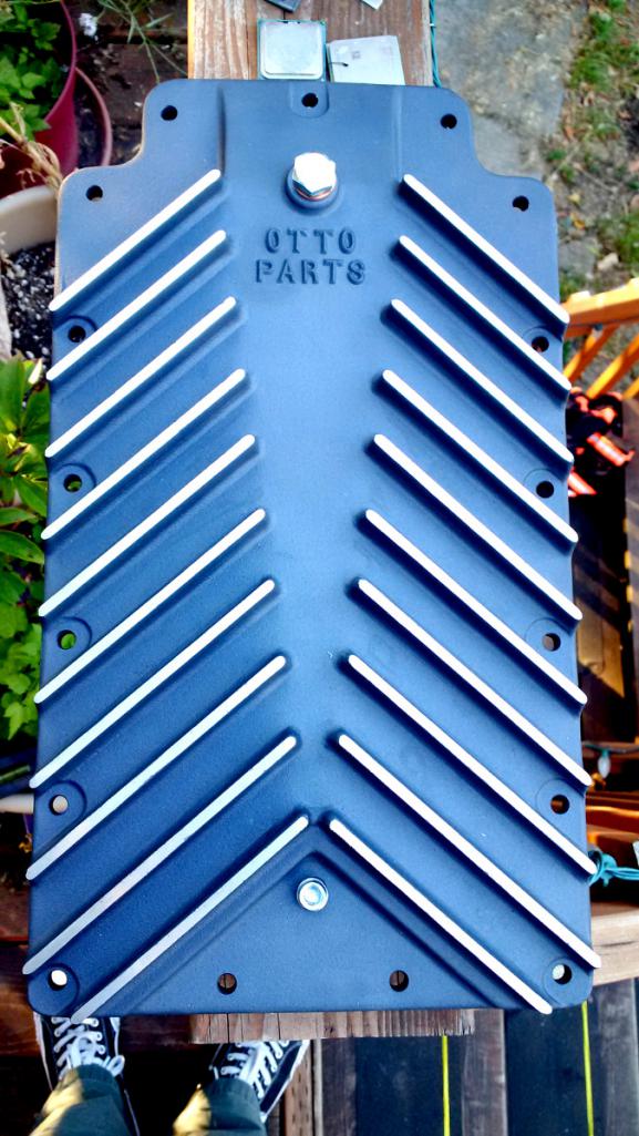
And here's the oil pickup installed: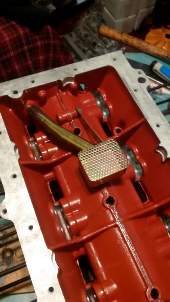
The Best Glass Tool of All Time: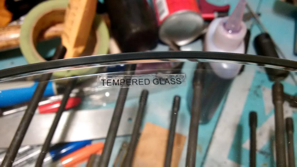
Here's checking the mating surface for flatness. Not pictured are the feeler gauges.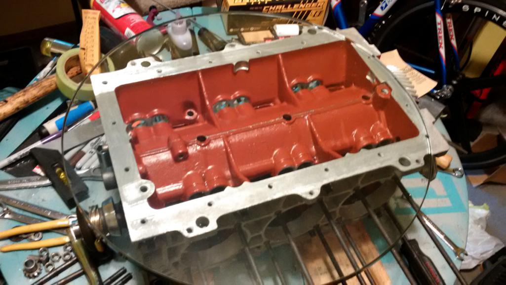
And here's a problem. I laid the oil pan onto the engine and it rocks something awful, like an 1/8" at the corner. At first I was freaked out thinking it might be the engine case. But it's not. Despite the beautiful machined finish of the oil pan mating surface, the trouble is indeed a manufacturing fault. I wrote a message to the vendor and hope to hear back from them tomorrow. Check it out: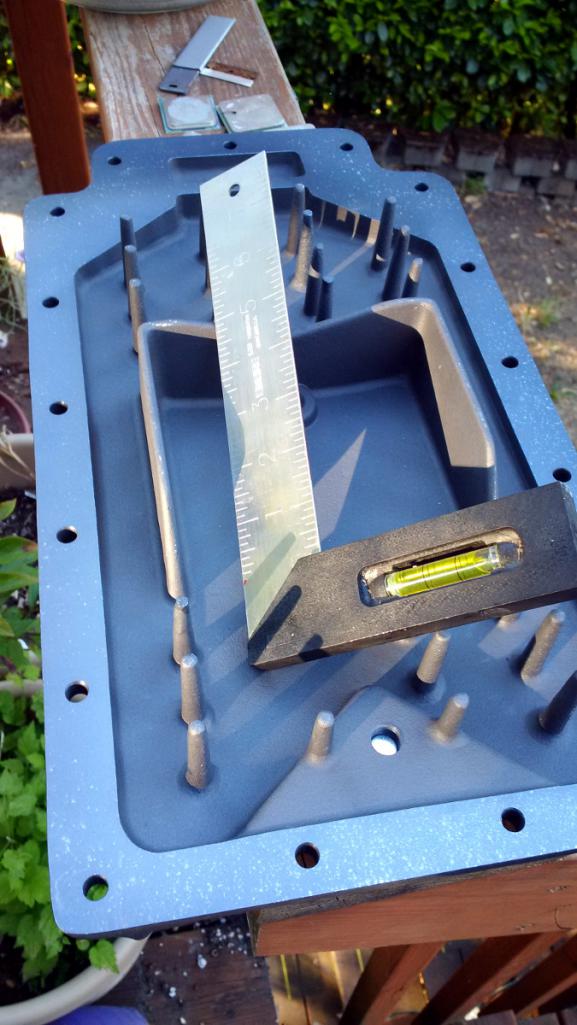
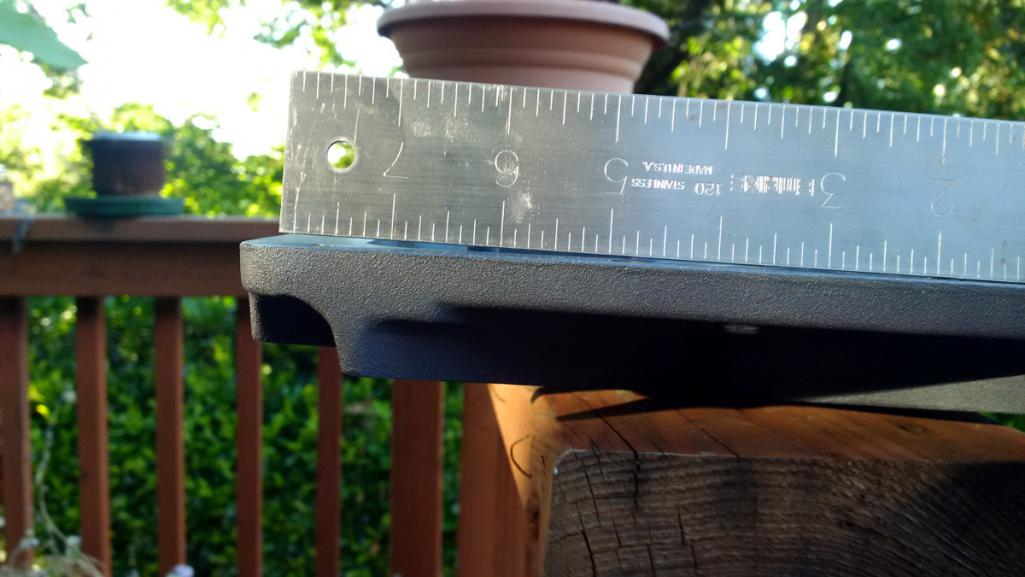
Yikes! That's not an easy bit of work to bolt onto a mill and re-surface. And even if I did I worry about the distance from the bottom of the oil pickup to the bottom of the oil pan. Hopefully it's not a big deal to get a better one.
Posted by: r3dplanet Jul 17 2017, 10:11 PM
While the oil pan issue is getting resolved, I'm turning my attention to the [choose a noun] cover. The service manual calls it the "engine rear cover." But some people refer to it as just the rear cover, or the front cover, or the pulley cover (even though it doesn't cover the pulley), the distributor cover, the oil pump cover, etc. I'm going to call it The Cover of Many Uses.
Here's a front and rear view with some helpful labels: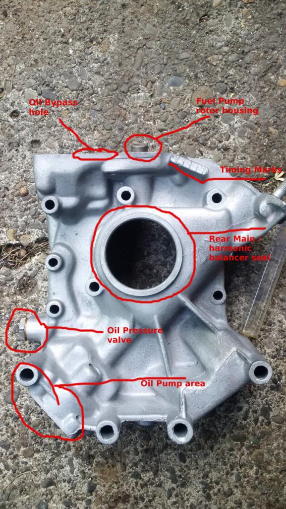
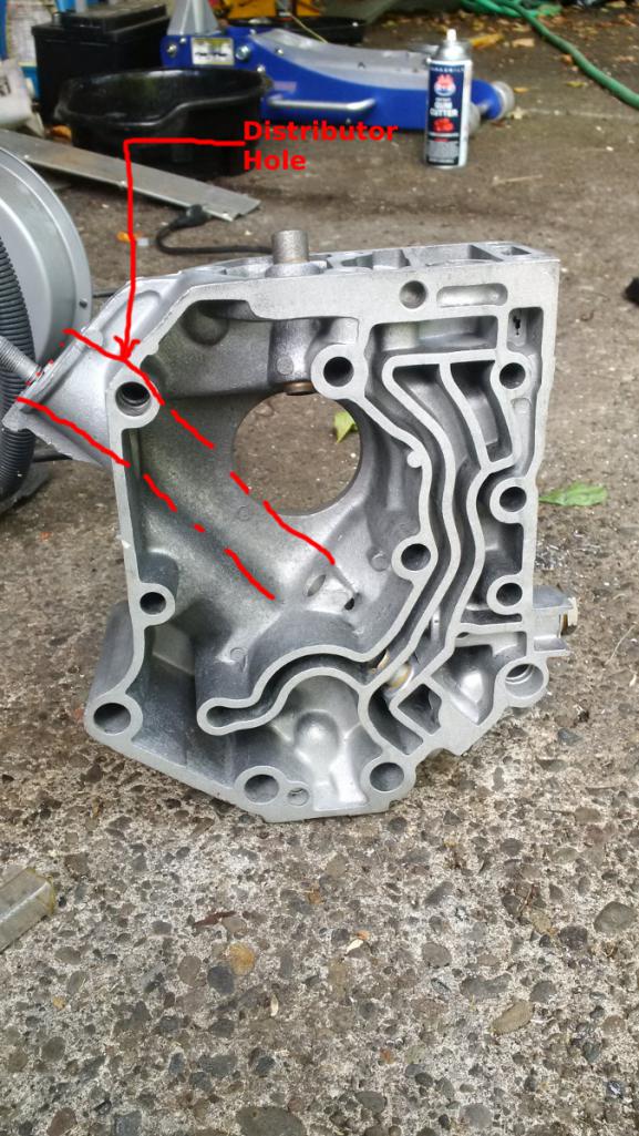
Here's something very important if you need to use a remote oil filter which is basically all 914 conversion adventurers. The stock oil filter needs to be cut off because it will try to occupy the same space as the firewall. So the oil filter neck is cut and threads tapped for hoses running to a remote oil filter.
Don't do the following! Read on to Page 9 instead!The Cover of Many Uses provides a perch for an oil bypass valve. If the oil filter should become clogged, or if the oil is very cold and thick, it builds up oil pressure. Should this happen then the bypass filter opens and routes oil back to the pan to keep oil flowing. One bit of trouble is that so does adding a remote filter. But oils and filters have come a long way since 1960 so it's not really a problem any more, especially if you like to change your quality oil and filter on schedule.
What could be a problem is that unless the bypass valve isn't modified (plugged) in some way, then the valve will always be opened and the oil will never get filtered. That's bad. So I'm using an old racer's trick to plug the valve opening with a nickel. This will force all of the oil through the filter. This is not an original Red Planet Industries epiphany. It's been done a thousand times by builders and tinkerers before me.
I didn't like the idea of using a nickel but I sorted through my huge glass jar of change and found a remarkably beaten nickel from 2014. If put back into circulation it would get pulled right away, so it became the candidate. The valve opening hole measured .802" on my cover, and that's not a measurement of a common object. So a nickel it was. I measured other coins I had also. A Mexican 50 cent coin works well, as does a 5 cent Euro coin, but the British £1 coin works best due to it's thickness. I just didn't want to spend a whole pound for this operation, and managed to save $1.26 in the process.
The nickel needed to be filed down a bit before I popped it in, peened the edge, and filled the gap with good old JB-Weld.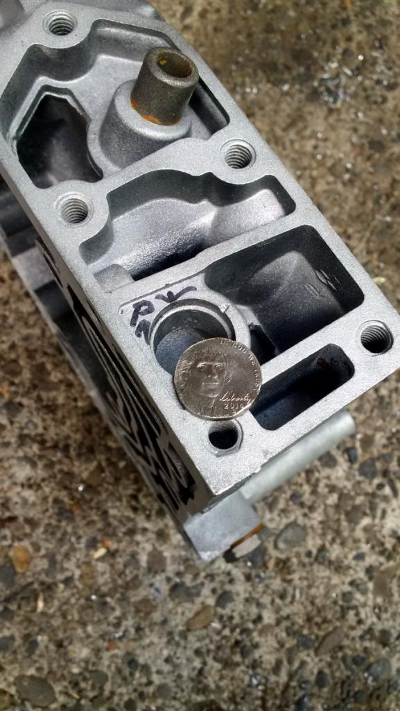
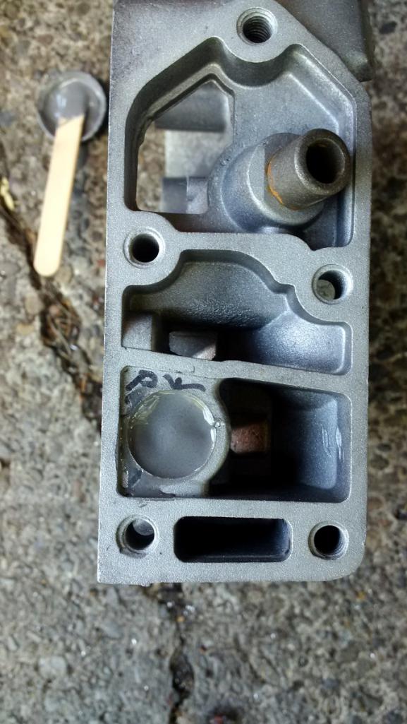
Still needed is the oil pressure valve bits (mine are worn) and the installation of the oil seal. I have the seal but the pressure valve bits are in the post. That's coming up... [i]in the future!
Posted by: r3dplanet Jun 3 2018, 12:39 AM
It's Saturday night and I'm full of steroids so I decided to do some more work on the engine. Tonight's project was to get the piston rings measured and installed. I'm using the piston rings that came with the AA pistons for the first and third rings, but the second rings are "gapless" Total Seal rings. If I had to do this job again I'm not sure I'd bother using the Total Seal rings.
Here's the setting on my coffee table: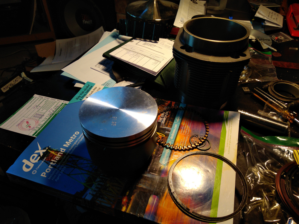
The first thing to do is to measure the gap in the empty space where the rings almost, but not quite, meet. I'm doing this for what amounts to five rings per cylinder x6 cylinders. In the past on other engines and parts, the gap is very often too small. I got lucky here and only had to file a couple of rings very gently. I'm using the rule of thumb that for every inch of bore, figure .0035 - .004. For 92mm (3.622 inches) I should aim for .013 - .015 thousandths. And I got exactly that. 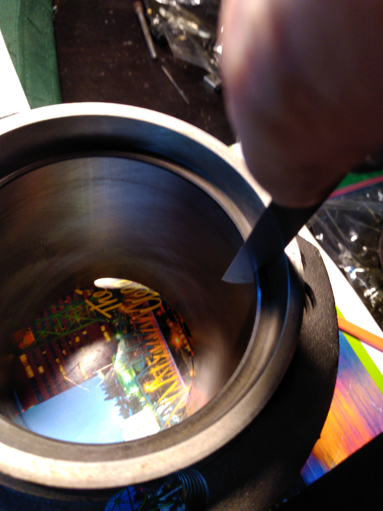
Starting with the rod side of the ring (or "bottom") the first ring to go is the accordion spacer ring. The ends butt against each other but do not overlap. This ring must go first before the other two that wedge on the upper and lower side. 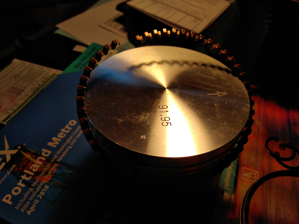
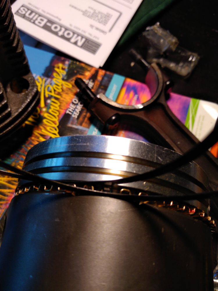
The Total Seal rings are a bit fiddly, and induce a vague sense of uneasiness. The instructions didn't seem to show my rings, but I snooped about online and found the orientation. First spiral on the larger ring, with the gap on the bottom. Then spiral on the very thin bottom ring into that gap. Gently squeezing around it seems to manage to work as one piece. I was careful to make sure the gaps of each ring were 180 degrees from each other. 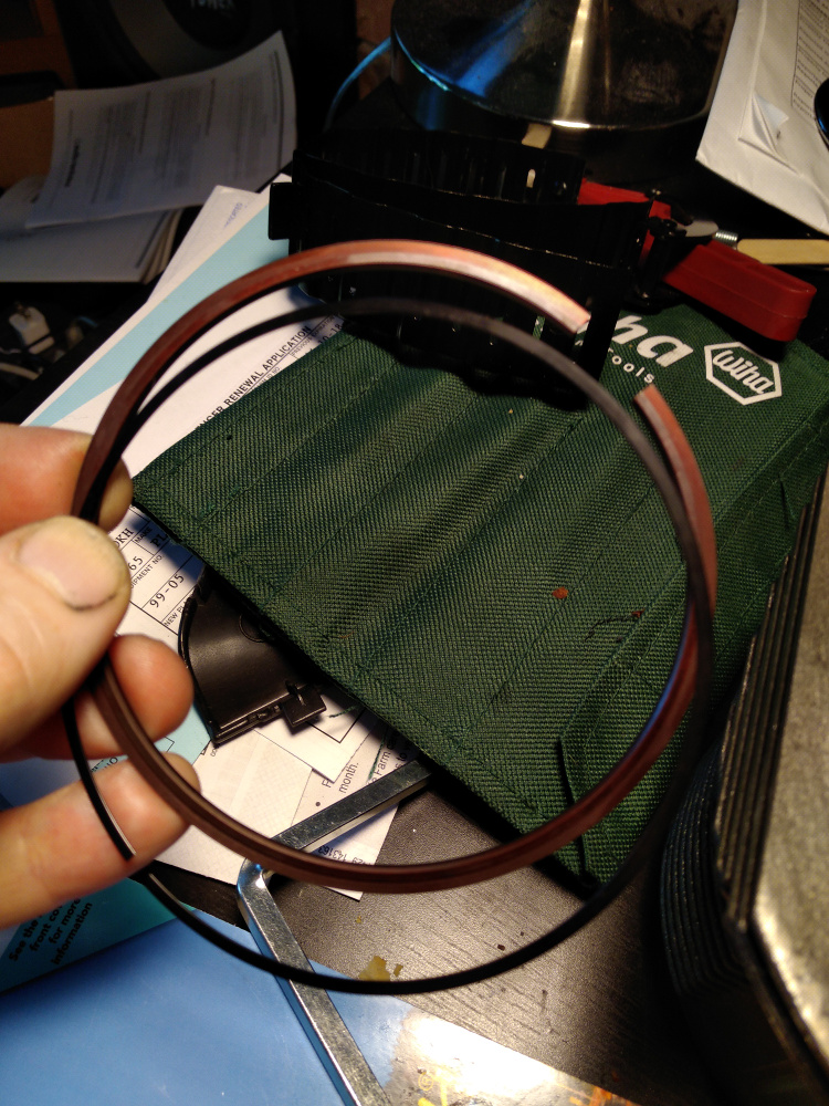
I'm just showing how the ring looks here. It actually installs upside down from what you see here.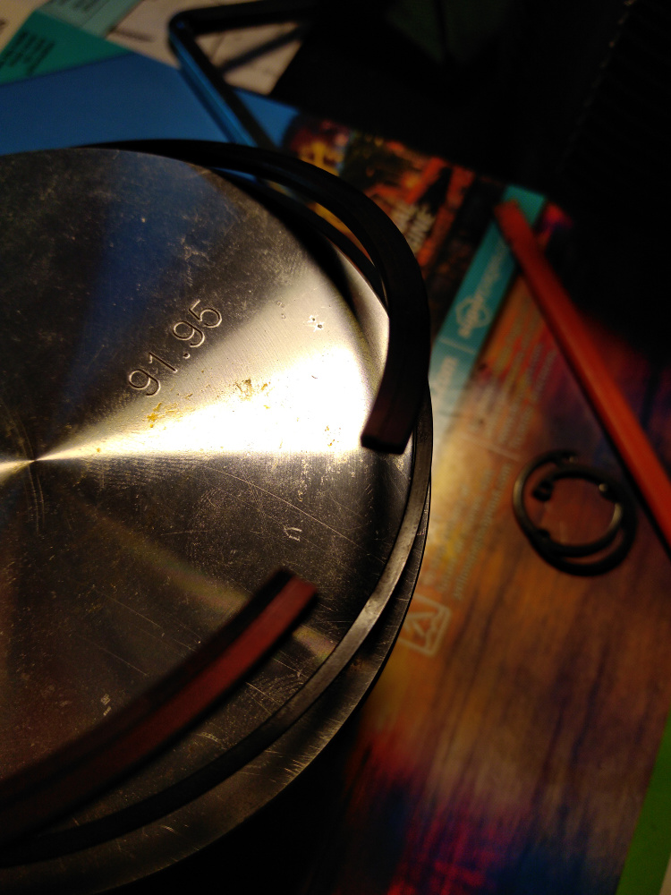
On the top ring you really have to look carefully for the "top" mark. Even a smear of oil hides the stamp. This one just spirals on like all the others.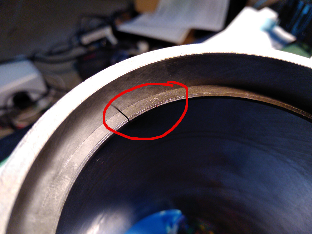
Now it's time to install the connecting rods. This can be done in two ways: first, assemble the piston, cylinder, connecting rods, and wristpins and then install the assembly into the block. Second, you could install the rods to the crankshaft and then install the pistons and cylinders and finally bork the wristpins in. I bumbled about both ways and decided on the first method.
I really wish the Mahle wristpin clips were as easy as these circlips to install on my BMW R75/5. What a farking pain the Mahle clips are. Ugh.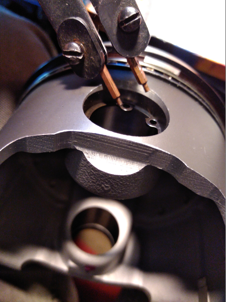
Here are three views of the left, center, and right side of the completed piston rings. Just for reference. I looked around online and never found the clarity I was looking for, so here it is. Not that I haven't spaced the ring gaps around the piston into their "final" position. This is just to highlight how the rings should fit. After this, I spaced them all 120 degrees or so from each other, making sure the 2nd Total Seal rings were 180 degrees apart. None of the gaps align with the wristpins. I honestly doubt this makes any difference as these rings will all spin about when the engine is running.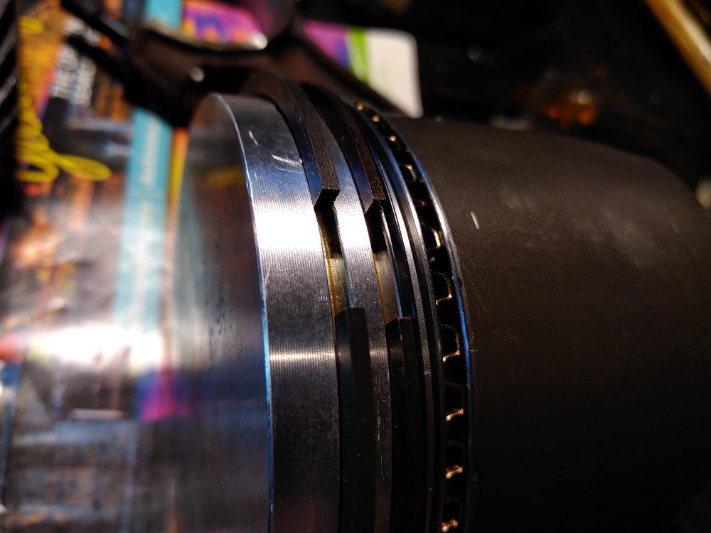
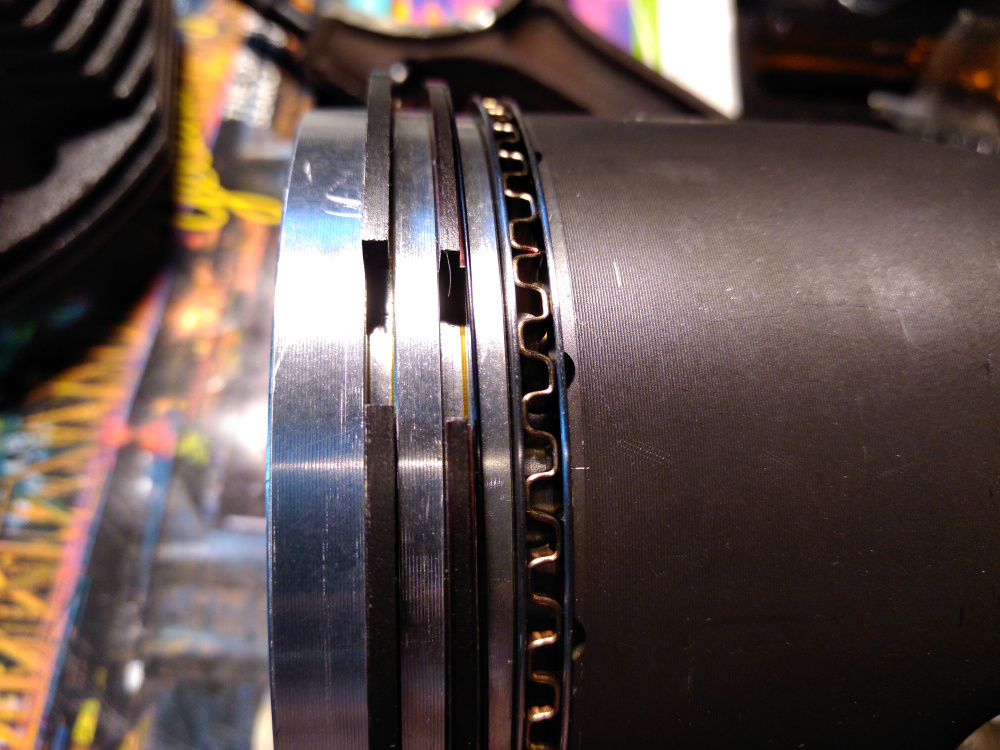
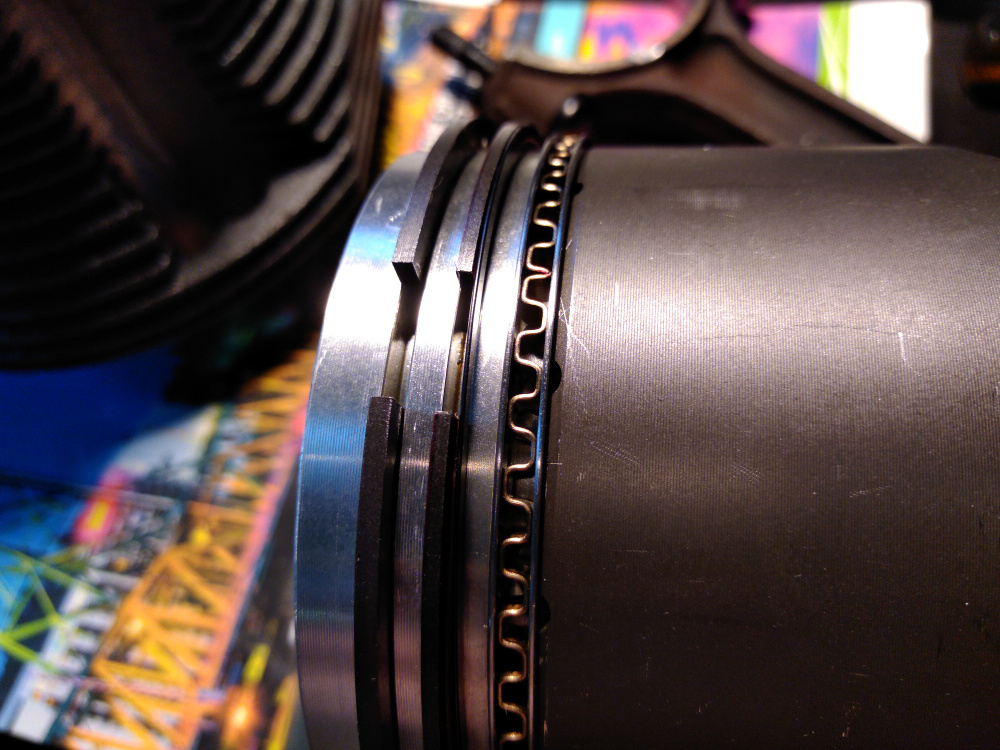
Last, here is the assembled piston and rod. Note the "#4" stamps on the big end at the bottom of the photo. This indicates that it's piston and rod #4 on the crankshaft. This stamp should point upwards, so it's legible looking down in from the top of the case. 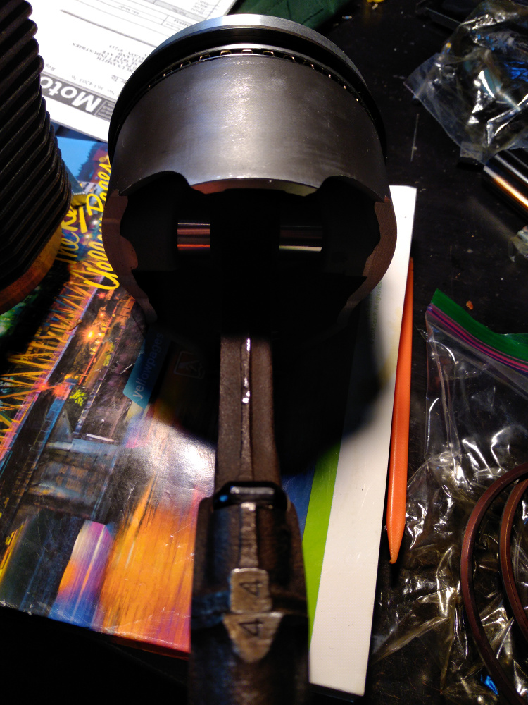
I assembled #3 and #4 first because I was worried about the clearance of the big end rotating inside the case. The head studs stick inside the case longer on these two registers and so I temporarily installed these two first and spun the crank to make sure. I have about 1/4" of clearance on each side. Not a lot of room, but it's enough.
Posted by: r3dplanet Jun 3 2018, 12:44 AM
Oh right. Oops. Here's photo of the whole assembly: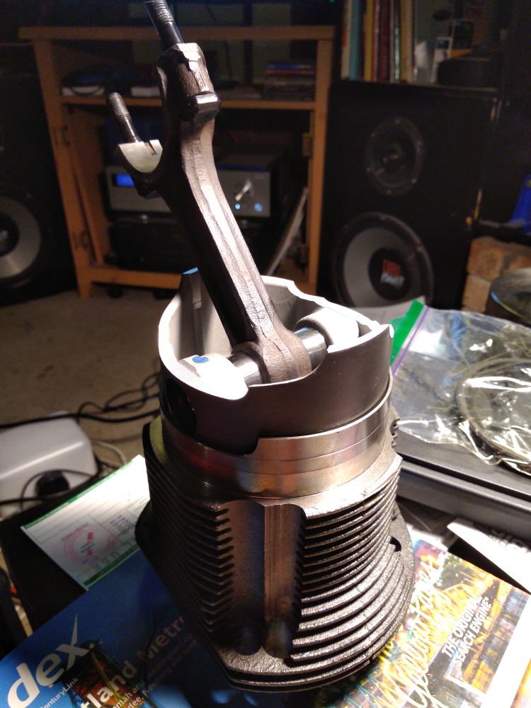
Posted by: JRust Jun 3 2018, 10:51 AM
Good to see you working on it Marcus. I know its been a long haul. Hope to see you at WCR this next weekend
Posted by: r3dplanet Jun 26 2018, 11:32 PM
I had to remove and install the cylinder assemblies a couple of times after my last entry. There was quite a bit of confusion as to which direction the pistons should point, and I ended up re-ringing every piston ring.
The conventional wisdom says that in a standard Corvair engine the pistons would normally point to the flywheel. Reverse rotation engines with stock Corvair cylinders have pistons that point toward the oil pump cover. But I couldn't find any info at all on which direction to point them if the engine is both reverse rotation AND has VW pistons and cylinders. I really do not want piston slap, but it may not be the end of the world if it happens. After consulting two engine builders who knew much about my project they said to point them toward the flywheel. So I did. Don't take this as gospel because it hasn't been tested yet.
I failed to get a photo, but each piston skirt is clearanced right next to the wrist pin housing. This is because the big ends of the pistons rotate so closely to each other inside the case that the piston skirt will butt into the the opposing rod cap. In order allow the engine to spin, each piston is installed with the clearanced section facing the inside of the opposing piston. Then in order to make all of the pistons point the same way, each pair of opposing pistons was installed one pair at a time (#1 + #2, #3 + #4, and #5 + #6) allowing a full rotation of the crankshaft to ensure a nice spin. Also, the pistons and rod caps are numbered only on one side where the cap meets the small end. They MUST meet. One more time: THEY MUST MEET. But they don't have to point upward. That is, the numbers can face to either to top or bottom of the case so long as the numbers face each other. Here's #1: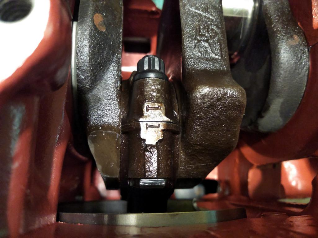
It happens that I had to flip two pistons and swap #5 and #3 to make it all fit correctly. No big deal. Just be aware.
I found a problem with the prior piston ring clearances. At previous clearances, the engine just really struggled to spin. To correct that problem I removed all the rings and re-gapped them to .016" for the top ring and .019" for the second ring. I also ditched the Total Seal 2nd rings. One reason why is because I broke two of them, and I think they were the main contributors to the binding.
Anyway, now all six are installed and it all spins nicely. Tight, but not too tight.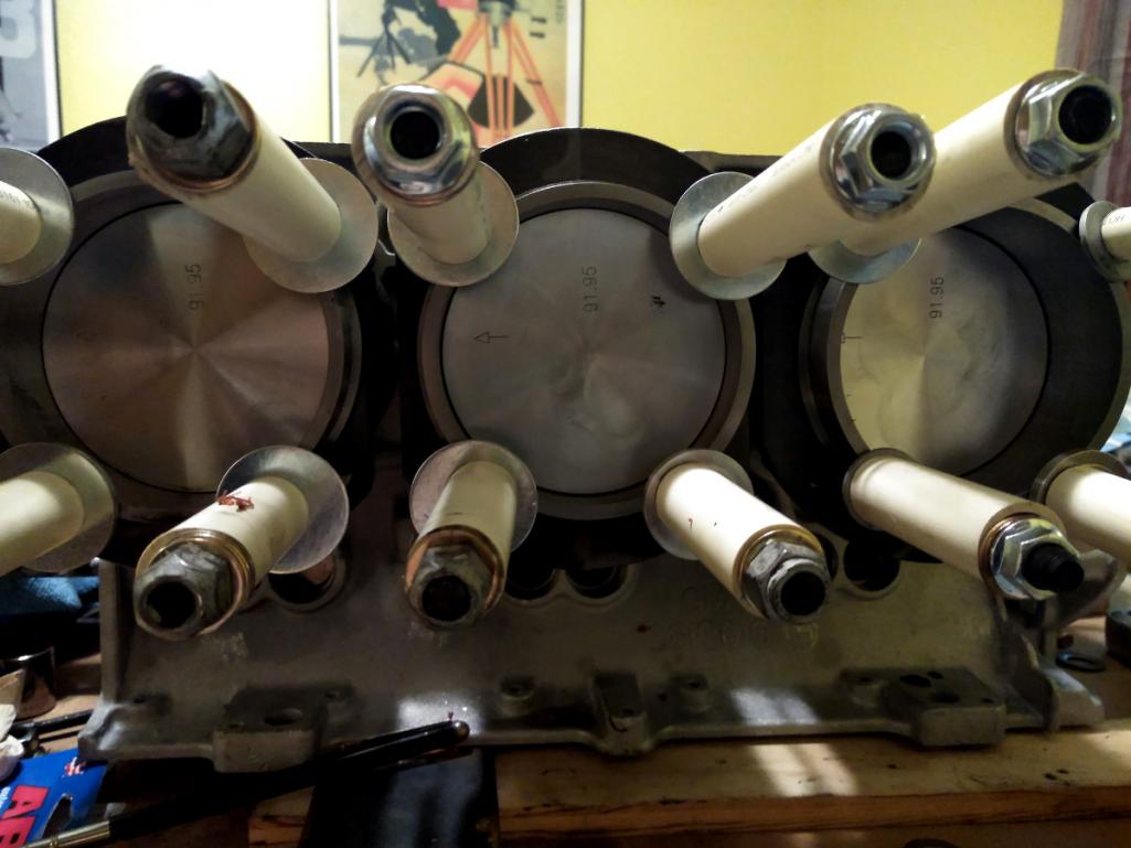
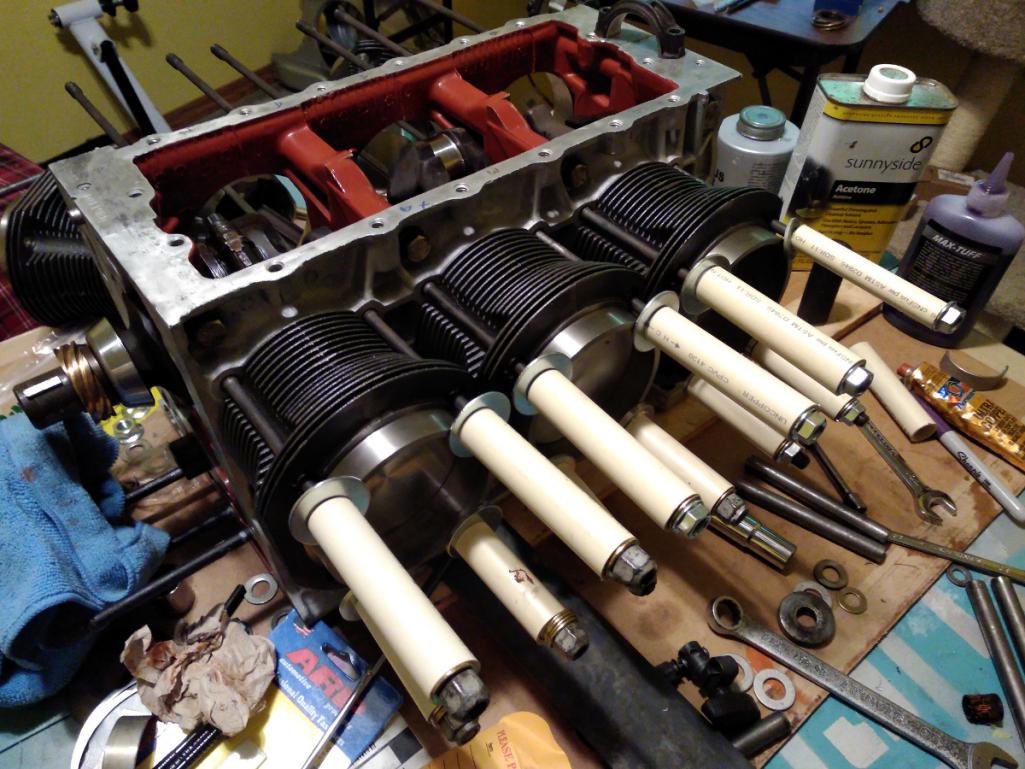
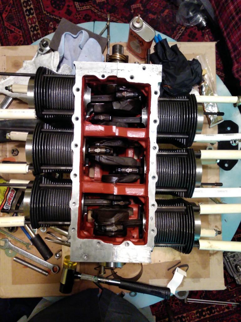
Now we can finally move on to the heads. Admittedly I had more trouble than I wanted, but I figured out all the trouble and rectified. The problem solving is enjoyable but thankfully it's moving faster and getting more fun.
Posted by: r3dplanet Jun 27 2018, 12:05 AM
Let's have some fun with the heads.
Here's a photo of the valves along with the .040" copper head gaskets. Yes, the heads are filthy. Yes, they are clean now.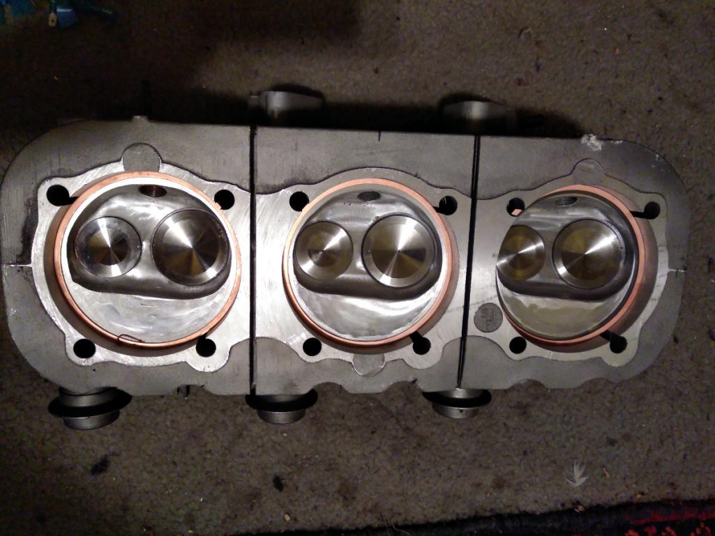
There are two things I want to do. First, I need to get a sense of the gap between the valves and the piston top. Second, I'd like to get the compression ratio together.
Using the tried and true Play-Doh method, I shoved a bunch of Doh into the combustion chamber and trial fitted one of the cylinder heads and torqued it down. The idea is to get a physical mold of the valve impression and then carefully measure the thickness of the squished Doh. 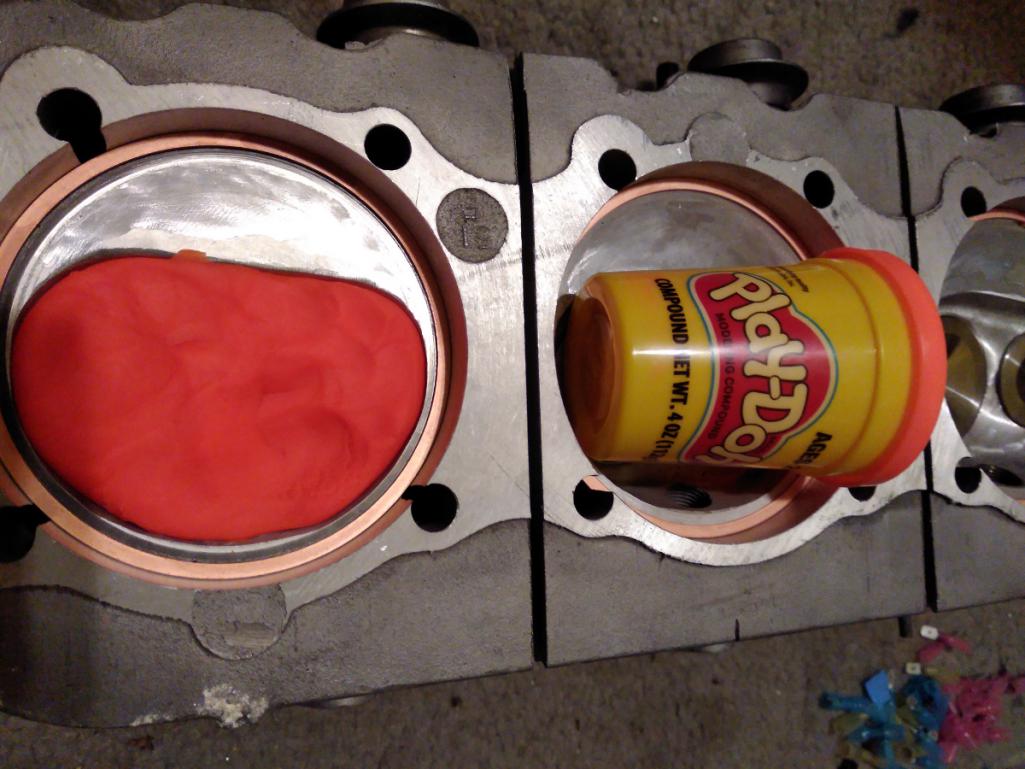
Note that I'm using .010" base gaskets (actually .0118") with a thin smear of copper RTV on the base gaskets. That plus the .040" copper head gaskets (well, .0386") I should have the correct .050" overall head gasket thickness. I fitted two solid lifters into the corresponding bores along with the stock pushrods and gave the engine two turns. I took it apart and realized I made the mistake of not using enough Doh, so I did it again. Ideal clearance is between .35"-.40", and mine measure .371". Crazy impressive and totally not my doing. That's the work of Tom Knoblauch who did the machine work on the cylinders, pistons, and elsewhere. Now that I know how to appreciate such things, I'm super appreciative!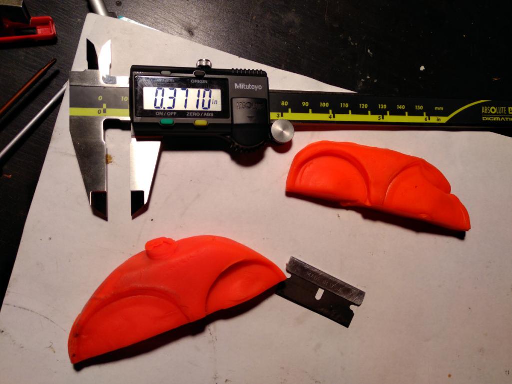
Then I realized that it was way too early to be doing this measurement because I'm not using stock pushrods or rockers. Oops. More on that later.
While I'm waiting for some parts to arrive, let's measure the volume of the combustion chamber. This is a well known method that I see all the time. It's not triple accurate, but it's good enough. I bought an acrylic plastic circle of 3-15/16" diameter and drilled two holes. One to fill with liquid, the other to capture and release air bubbles. I'm using Water Wetter because it has good contrast and low surface tension. I'm sure you have all seen this a million times before. I had to do this process a number of times either because I had bubble trouble or just sloppy technique. But the result is an average of 51cc from all three chambers. They were actually dead nuts accurate as far as my testing ability goes.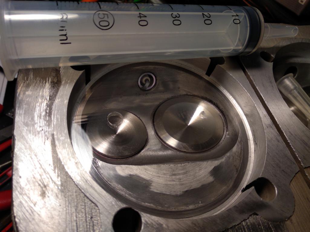
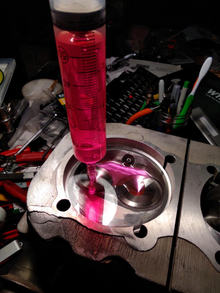
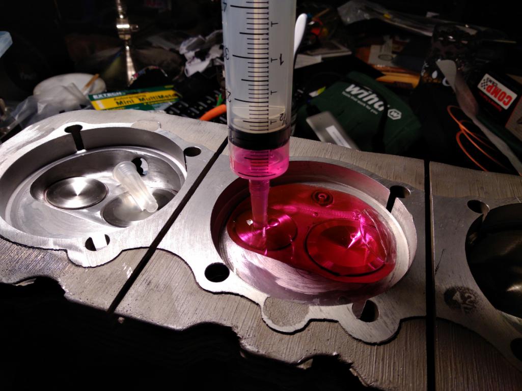
Running the info through various online calculators shows that I have a 9.35:1 compression ratio. Nifty. That's very close to the factory 9.25:1 ratio, and not enough to bother with using thicker gaskets to compensate. If anyone cares, here's the data:
Bore: 92mm
Stroke: 2.94"
Deck height: 0
Piston dome/dish: 0
Chamber volume: 51cc
Number of cylinders: 6
Compressed gasket thickness: .050"
= 9.35:1
I hope that whoever ends up with the engine will be good enough to use high octane non-ethanol fuel, as a gentleman always should.
Posted by: Porschef Jun 27 2018, 04:23 AM
Cool stuff, and hopefully a little diversion from the not cool stuff.
Posted by: DaveO90s4 Jun 28 2018, 03:16 AM
Hi Marcus - great to read about your progress.
Are you still going to use the spring loaded idler? I was strongly advised not to on my reverse rotation engine - the pulley being on the 'pull' side of the crank and that tension overpowering the spring etc. on my engine all is working well with the standard set up.
And you say above "whoever gets this engine" - are you not going to put it into your 914 after all?
Feel free to email me any time - I think you'll still have my email address.
Cheers
DaveO
Posted by: r3dplanet Jun 28 2018, 12:05 PM
You know, that's a really great question. I had intended to use it right up until you mentioned this. I thought that whole point behind the spring loaded idler was to prevent belt failure on reverse rotation engines. Hmm..
Posted by: 1adam12 Jun 28 2018, 02:10 PM
Your progress is looking great Marcus. I was contemplating this swap a few months ago but sticking with the flat4. I even had a talk with California Corsairs which is right down the street from me. They had blocks stacked up to the ceiling there!
Here's some inspiration for ya from some shop images I took from there...
Attached image(s)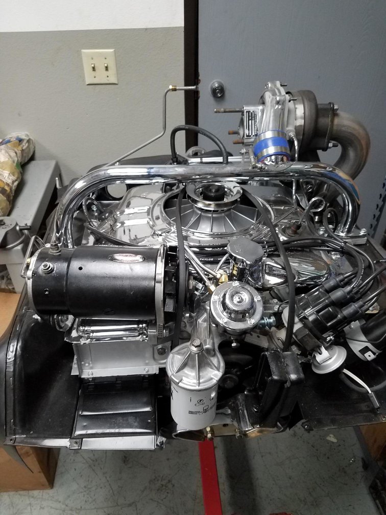
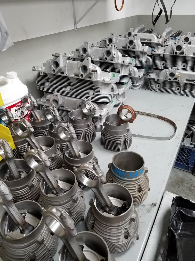
Posted by: r3dplanet Jun 28 2018, 02:12 PM
Ha! Look at all that! Very cool! Maybe I should drop the compression and add a turbo.
Posted by: DaveO90s4 Jun 28 2018, 03:41 PM
Hi Marcus,
Have a close look at the generator cooling blades on the photo that Adam posted. Vairy interesting indeed methinks. What to infer from that?
DaveO
Posted by: r3dplanet Jun 28 2018, 09:50 PM
Yeah, right? That's a reverse rotation alternator fan on a stock generator that doesn't spin backwards. Interesting. Maybe someone rebuilt the generator into an alternator?
Posted by: r3dplanet Jun 28 2018, 10:09 PM
More progress today and it's all about vanity. I pulled out the powder coating gear and coated some things. Also made an unpleasant discovery along the way. The long block is getting about finished but on pause due to some more head gaskets on order. Plus it was a nice day and I didn't have to spend it connected to a medical probe-u-lator.
Most of the parts are cast aluminum and so really don't need to be prettied. Nobody will see them. Eh. Because they're cast they cannot be anodized so powder it is. First up, the engine cover / fan housing got some treatment with a little file to remove a million little casting boogers. I wish I would have taken the extra time to polish the whole cover because it didn't turn out super in the end. But it's nice enough. Actually, I wish GM had done a better job and polished it but.. eh.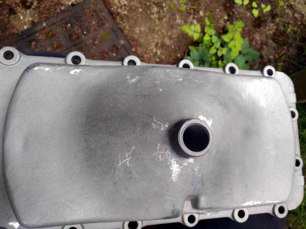
This is the largest piece I've ever put into my little bench top oven and it barely squeaked in. I put together some alumin(i)um mounts to move it about without bothering the powder. More machine gray.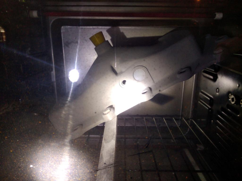
Then it was off to do the dipstick tube and oil filler cover. Here's the unpleasant discovery. It's full of what I think are glass beads from the blasting process from the guy on eBay from whom I purchased it. This would have a been a super quick way to kill the engine if assembled this way. This sort of thing drives me nuts, bananas, crackers, or any other snack food euphemism one cares to invent. I pulled out the rotary tool and polished it's innards and then cleaned it with mineral spirits and a brush. Took five minutes. I can't understand the mind of the seller who couldn't be bothered. Just a little quality control could save an engine. I'll be he has worms in his brain. It wasn't obvious as the oil pump pressure plunger was already installed. Unless I took steps to remove it for inspection it would have made for a really bad outcome.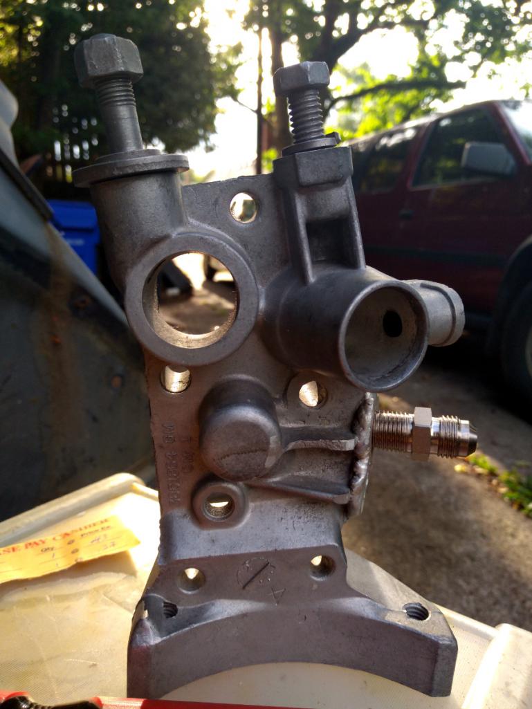
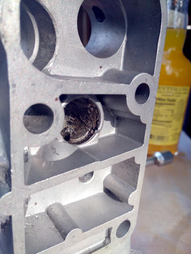
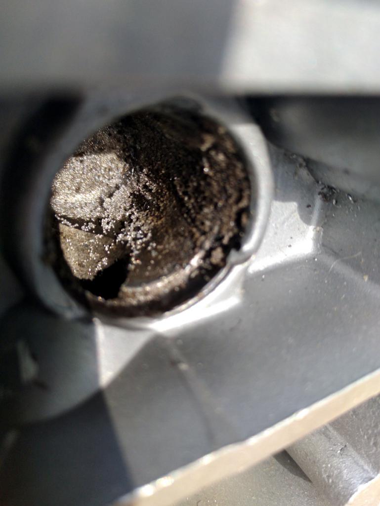
I didn't get any photos of the Cover of So Many Uses but it was coated also. So are the pushrod tubes but I did those with high-temp silver and then polished the business ends. It's traditional to paint them white, and I may yet for No Good Reason.
The day's tally: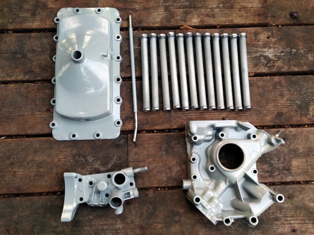
Posted by: r3dplanet Jun 28 2018, 10:13 PM
I'll be installing the pushrod tubes very shortly. There are twelve of them of course. Thinking about the concept of "twelve" today brought this to mind:
https://www.youtube.com/watch?v=VOaZbaPzdsk
Posted by: worn Jun 28 2018, 10:29 PM
Yeah, right? That's a reverse rotation alternator fan on a stock generator that doesn't spin backwards. Interesting. Maybe someone rebuilt the generator into an alternator?
Sure looks great! Your posts show a lot of detail. In reference to the blingish images above, which way does that belt turn in a stock motor? Sorry to be so simple about these. Rode in a new one once upon a time but know so little.
Posted by: r3dplanet Jun 28 2018, 11:00 PM
Good question. I've hardly thought about it until now. If you scroll up and look at the engine photo posted by 1adam12, have a look at the big fan in the middle. On a stock engine it will rotate clockwise. Naturally in a reverse rotation engine the fan spins counterclockwise. That has historically caused trouble with throwing belts. I'm going to have to investigate this when the time comes. DaveO90s4 knows more than I do.
Yeah, right? That's a reverse rotation alternator fan on a stock generator that doesn't spin backwards. Interesting. Maybe someone rebuilt the generator into an alternator?
Sure looks great! Your posts show a lot of detail. In reference to the blingish images above, which way does that belt turn in a stock motor? Sorry to be so simple about these. Rode in a new one once upon a time but know so little.
Posted by: r3dplanet Jun 28 2018, 11:12 PM
A little follow-up from the previous modification where a nickel was stuffed into the oil bypass hole. After third thoughts and some social confirmation, there's really no reason to do this. So it's time to free Thomas Jefferson.
Torches and digging: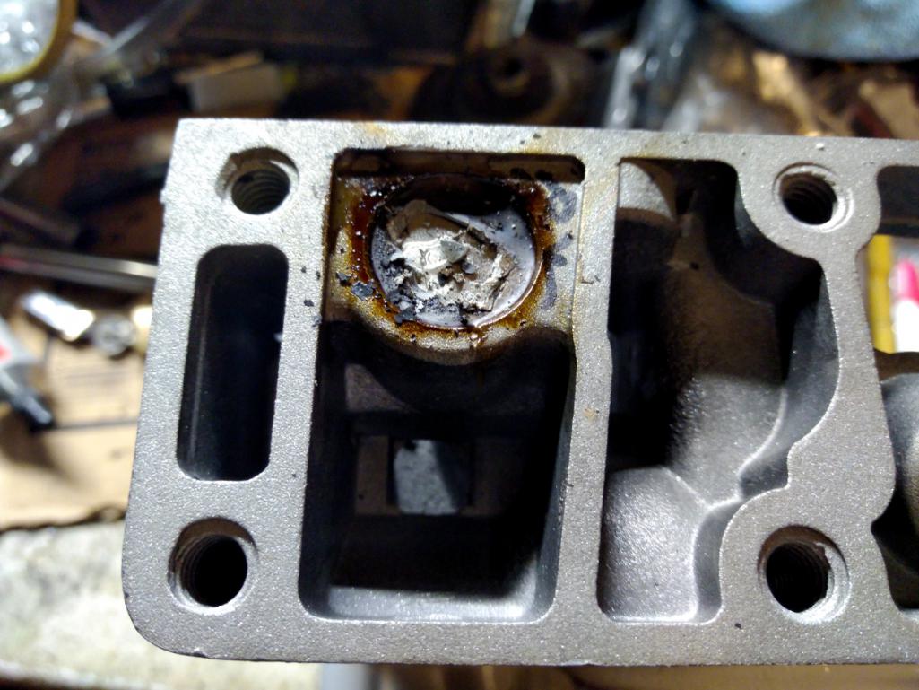
Tom looks pissed. He has every right to be. I feel bad because I always liked the guy. Except the slavery part. You can just see the disappointment on his face, "Marcus! Get me out of this damn hole!"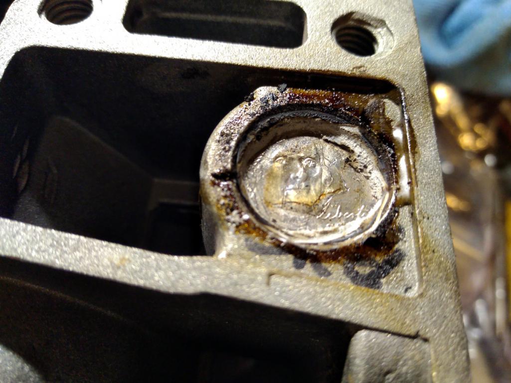
Now I have a perfectly good nickel.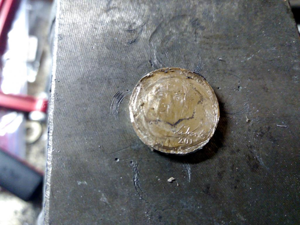
And finally a little cleanup. Good as new.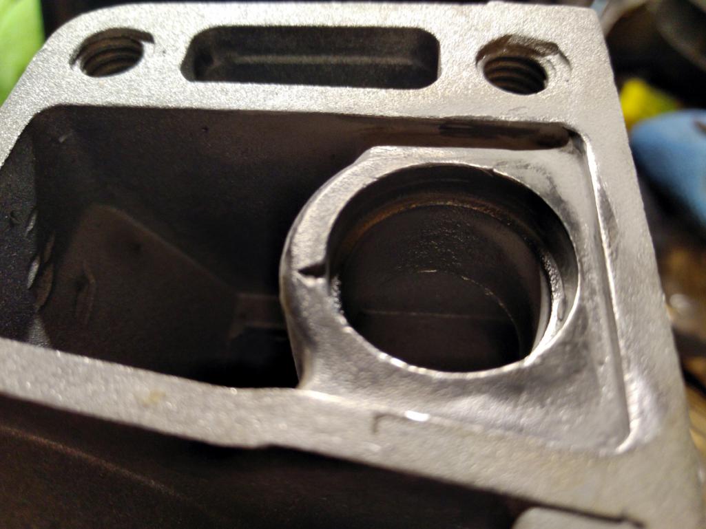
Posted by: DaveO90s4 Jun 29 2018, 02:09 AM
I think Marcus meant to say:-
Good question. I've hardly thought about it until now. If you scroll up and look at the engine photo posted by 1adam12, have a look at the big fan in the middle. On a stock engine it will rotate counterclockwise. Naturally in a reverse rotation engine the fan spins clockwise.
(In a normal Corvair engine the crank will pull the fan belt from the horizontal fan via the alternator pulley. Thus the alternator is on the tensioned side of the belt. With a reverse rotation engine the alternator is of course on the less tensioned part of the belt travel)
Posted by: Tbrown4x4 Jun 29 2018, 02:50 AM
. It's traditional to paint them white, and I may yet for No Good Reason.
Traditionally, the white paint is VHT high temp, and is only used on the tube end closest to the exhaust stub. This helps prevent the exhaust heat from transferring to the o-ring on that end and to the oil draining through the tube. The tube also helps dissipate heat from the oil, so the opposite end of the tube stays unpainted (or only lightly painted).
Posted by: r3dplanet Jun 29 2018, 12:26 PM
Thanks! That's good to know. I'll make the modification to mine today.
. It's traditional to paint them white, and I may yet for No Good Reason.
Traditionally, the white paint is VHT high temp, and is only used on the tube end closest to the exhaust stub. This helps prevent the exhaust heat from transferring to the o-ring on that end and to the oil draining through the tube. The tube also helps dissipate heat from the oil, so the opposite end of the tube stays unpainted (or only lightly painted).
Posted by: r3dplanet Jun 29 2018, 10:56 PM
Today just had enough room in it to put together the cooling fan bearing assembly.
I bought a bearing and polished aluminum housing and then squished them into place. On the subject, does anyone want my old Snap-On hydraulic press? It disassembles, which is nice, because it stands seven feet tall. It needs plenty of love but if anyone wants to come and get it they can have it for nothing.
Here's the pressed bearing and housing.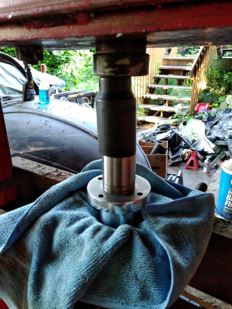
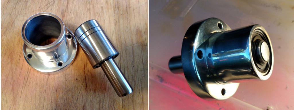
Then the tricky bit. It may not seem like it but pressing the bearing shaft into the engine top cover needs to be a precise exercise. The distance from the deck to the top outer diameter of the bearing needs to be between 4.46"-4.49". The idea is that when assembled there is a critical gap distance between the fan blades and the engine cover. Too close and it will make contact and be sad, too far and the forced air won't make enough pressure to cool the engine. I spent quite a lot of time trying to get this just right. If you ever do this, I think the easier measurement is the gap between the bottom of the bearing housing and the top of the fan cover, which is .040". Yes, I know the powder coating looks crappy.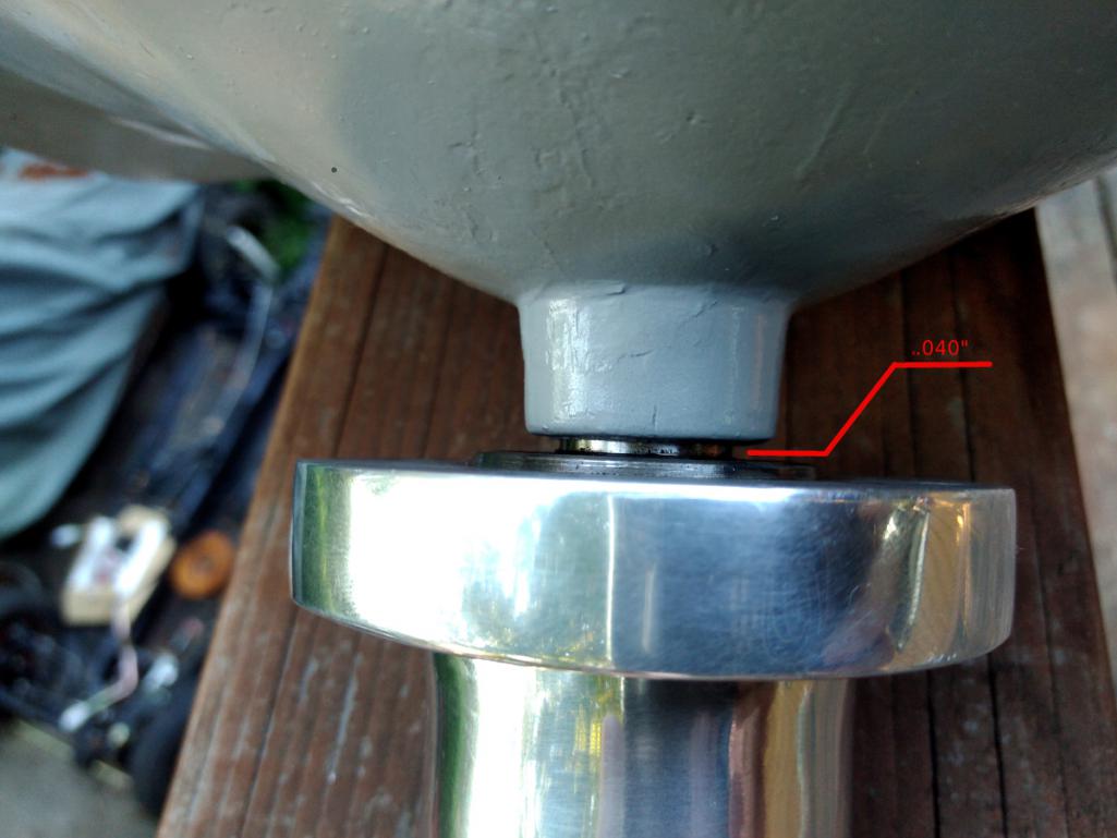
I still need to find the fan-to-cover measurement, the one that really matters. I'll find it and report back. With gaskets in place it looks to be 1/4". Here's what it looks like mocked up with the bearing, fan, pulley, and cover.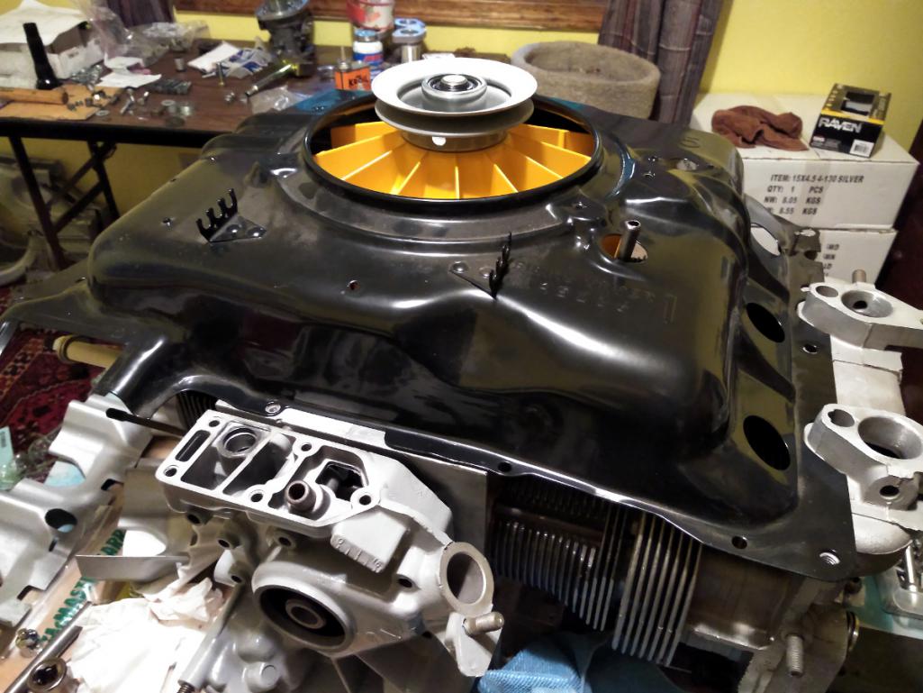
You might be thinking, "Marcus, the orange looks terrible. Your color sense is lacking and your sensibilities are crude." And you be right. I coated the fan to match the car, but now it looks loud and out of place. Oh well. Orange it is. I happen to like orange a lot but I get your point.
On the subject of fans, here's the vertical fan setup I drool over. I think it would look much more at home in the 914. I want one more than I want my next breath. Feast your pupils:
http://americanflat6.com/products/verticalfans.html
Posted by: DaveO90s4 Jun 30 2018, 06:01 AM
Dear Marcus, re vertical fans. I very very respectfully disagree:-). Vertical fans are just oh so passé. Every 914-6 has them. The horizontal fan is - in a 914 - pretty unusual.
And the horizontal fan works.
And there is damn allclearance in that area too in a 914-C6. What with the crank pulley very close to the firewall, the firewall sloping back into the engine bay as it rises, the air restriction into the fan and the difficult tight turn the air has to take to get into the fan aperture.
Plus how to top er up with oil? And how to readily accesss the Cover of Infinite Uses?
I'm inclined to think for normal road use it is a solution to a problem that does not exist.
(Note: all above comments with respect to Corvair engine in 914. I make no comment re clearance etc for Porsche engine in 914 engine bay)
And I like the orange fan too:-)
Cheers
DaveO
Posted by: r3dplanet Jun 30 2018, 11:26 AM
Geez, is pragmatism all you have to offer?
Dear Marcus, re vertical fans. I very very respectfully disagree:-). Vertical fans are just oh so passé. Every 914-6 has them. The horizontal fan is - in a 914 - pretty unusual.
And the horizontal fan works.
And there is damn allclearance in that area too in a 914-C6. What with the crank pulley very close to the firewall, the firewall sloping back into the engine bay as it rises, the air restriction into the fan and the difficult tight turn the air has to take to get into the fan aperture.
Plus how to top er up with oil? And how to readily accesss the Cover of Infinite Uses?
I'm inclined to think for normal road use it is a solution to a problem that does not exist.
(Note: all above comments with respect to Corvair engine in 914. I make no comment re clearance etc for Porsche engine in 914 engine bay)
And I like the orange fan too:-)
Cheers
DaveO
Posted by: r3dplanet Jul 1 2018, 11:37 PM
There's a bit to know about rocker arms if you ever take this path and build your own engine. The stock rockers are just fine for a stock engine. They are made of stamped, hardened steel. The business end of it slides along a fixed radius, keeping in contact with the valve stem at all times. But there two undesirable characteristics. First, they can be inconsistent with one another and may not be suitable for big bore engines. Second, all that friction creates a lot of unnecessary heat.
To rectify this you can go with a full roller setup, but that is expensive for the set that Clark's sells, or you can spend even more and get a bespoke roller cam and lifter combo. The rollers do away with the stock girdles (pushrod keepers) and use a larger, rigid bar instead. Also required are longer, stronger ARP studs and bigger valve covers. Some vendors use lovely but lousy Chinese-made rollers that blow apart rapidly. These are the ones that Dr. Evil put into his bus engine. I was very tempted to buy them as well but quickly walked away after Dr. Evil's unwelcome experience. If you look through Corvair forums you'll see that this particular product has lots of similar failures.
A whole roller set wasn't in my budget so I'm going with the next best thing - small block Ford roller tip rockers manufactured by Comp Cams. These are also used in some Olds models. So yes, Ford parts in my GM/VW engine because why not? The part number is 1442-16. These are ball mounted, not stud mounted. The steel is thick and hardened and very strong. Racer approved. I'm just using them to keep the heat down.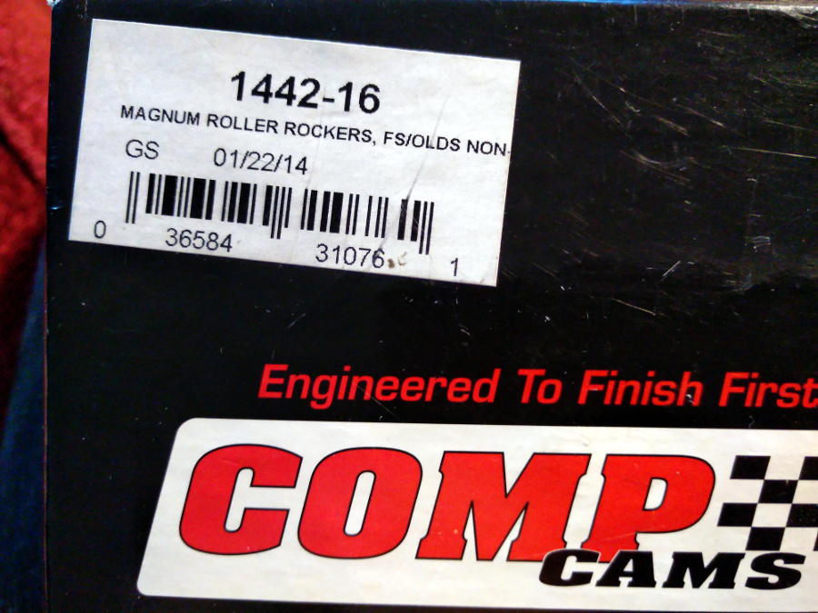
Why these roller tip rockers? Lots of reasons: way stronger than stock, less heat / friction, a fraction of the cost of a full roller assembly, and the lift ratio is very close the stock Corvair ratio, which itself is a matter of some debate. They do need to be modified. On the large central stud hole one side needs to be clearanced so that when mounted it will pivot far enough over to allow the roller tip to ride evenly over the valve stem. Also, the oil hole points directly down thereby filling up the chamber with oil. So the hole needs to be welded up and another oil hole drilled on the other side so oil shoots into the right place.
Here is are the original oil holes welded up.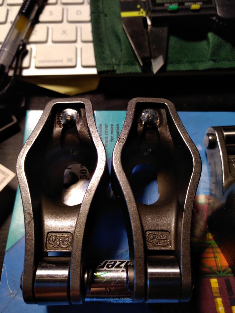
And new drilled oil holes on the other side.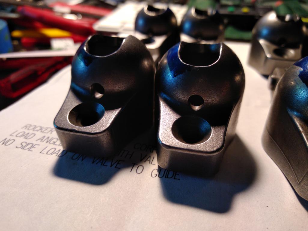
And all of them together. On the top row are the for the intake valves, the bottom row for exhaust. Be sure to order the matching pivot ball mounts if they don't come in the box. The balls mounts have four serrations to allow for more oil flow.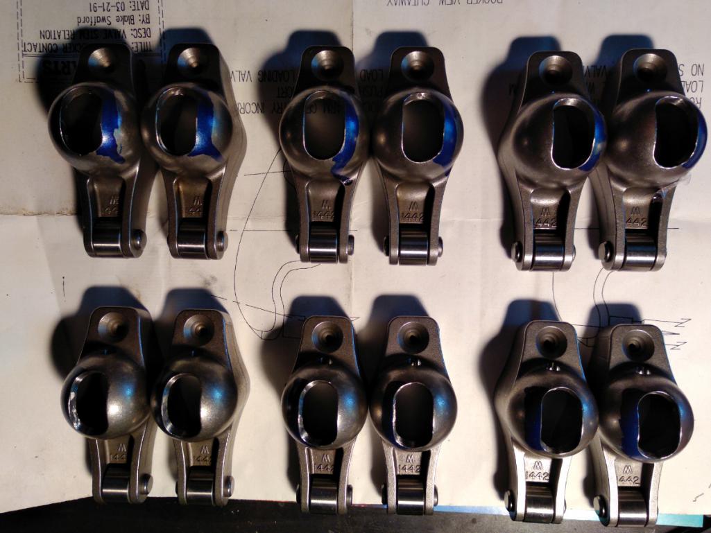
Posted by: r3dplanet Jul 2 2018, 12:08 AM
With the rocker arms sorted out it's finally time to doodle with the rocker geometry.
With non-stock cam, cylinders, base gaskets, and head gaskets it's reasonable to think that the stock pushrod length will be incorrect. So I ordered from Clark's an adjustable pushrod toolkit that comes with two adjustable pushrods and a pair of solid lifters.
The idea is simple: when the valve opens and closes the valve stem tip needs to travel smoothly along the roller tip. Or the roller tip needs to travel smoothly across the valve stem tip. Not too high, not too low. So if the head and base gaskets are correct (I double checked mine and they are) then all that needs to be done is to lengthen or shorten the adjustable pushrod to make it kosher.
First I do this visually. At rest the roller tip should be towards the bottom of the valve stem, and at full lift the roller tip should be towards the top of the valve stem. Here are exaggerated pics to show the difference.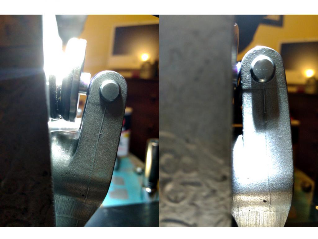
And here is a top view of the roller tip touching the valve stem. It really needs to roll along very flat on the valve stem. If the rocker wasn't clearanced to one side, it couldn't be made to ride flat.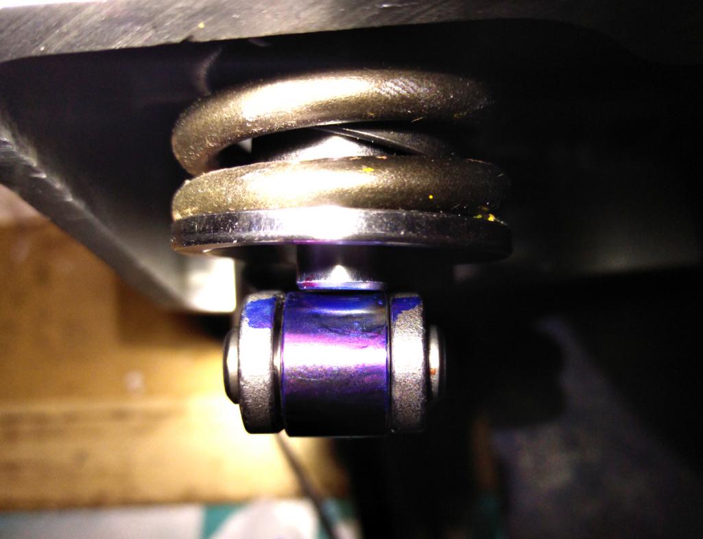
The instructions say to use a little piece of oiled paper and squish it onto the valve stem. This leaves a circular impression with the roller path clearly visible. It needs to be as close as centered as possible. I used blue Sharpie on the roller tip instead because it was easier to read.
The tolerance is about 1/2 turn on the adjustable pushrod, or .025" by my measurement. A little note here about tolerance: pushrods are available in different sizes, so the choice is made to the nearest .025". Not the end of the world if off by a little bit.
The pisser is that the solid lifter in the kit has a lower contact point with the pushrod than the hydraulic lifters. I'm using Melling JB-817 lifters. The difference in height of the contact point is 0.109" lower for the solid lifter. That means that in addition to getting the adjustable pushrod just right, this distance needs to be subtracted. Depending on the hydraulic lifter you use, this distance can be different.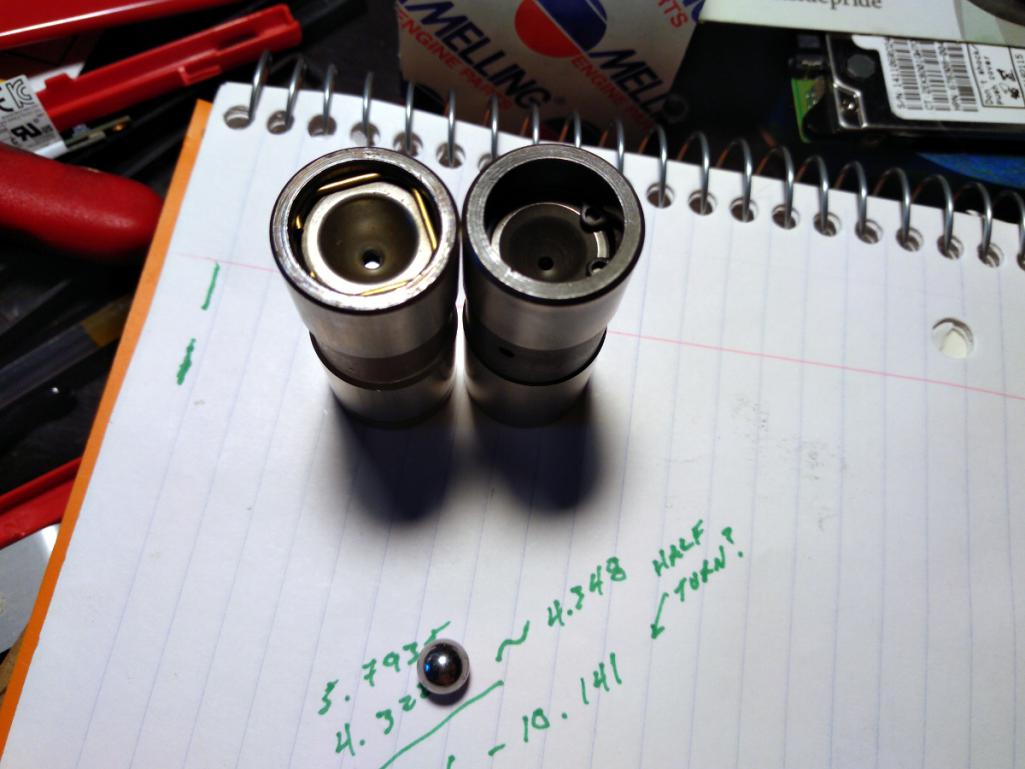
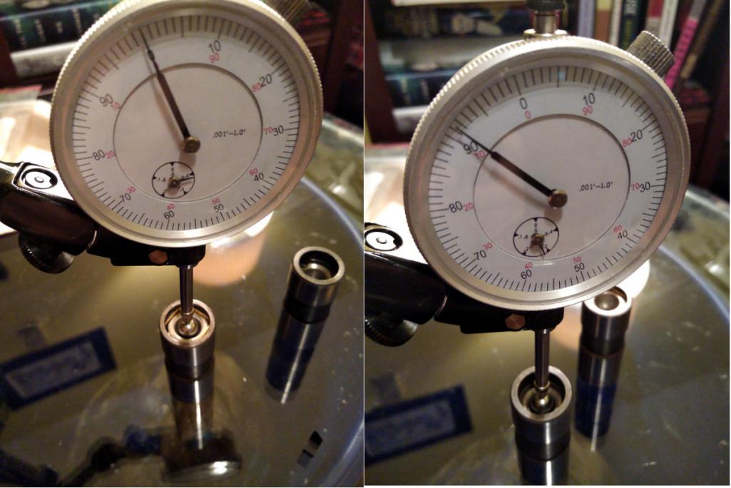
Then it's time for the arithmetic. This is where I get confused on what should be a simple task. The desired pushrod length is supposed to be the adjustable rod length + the lifter difference - the valve preload. Depending on the source, the pre-load is anywhere from 1/4 turn to 3/4 turn. So I'm using 1/2 turn, or .025".
.... and doing so leaves me with a pushrod 0.20" SHORTER than stock. This blows my mind because every other write-up I've studied with VW big bore stuff shows a longer pushrod. Not shorter. I averaged my two best lengths and averaged them to get 10.040". I measure the stock rods at 10.240".
The trouble here is that (a) I'm not sure this is correct and (b) I can't find shorter pushrods in this size. I might sacrifice one of my new hydraulic lifters by welding it solid and measuring again. Bummer.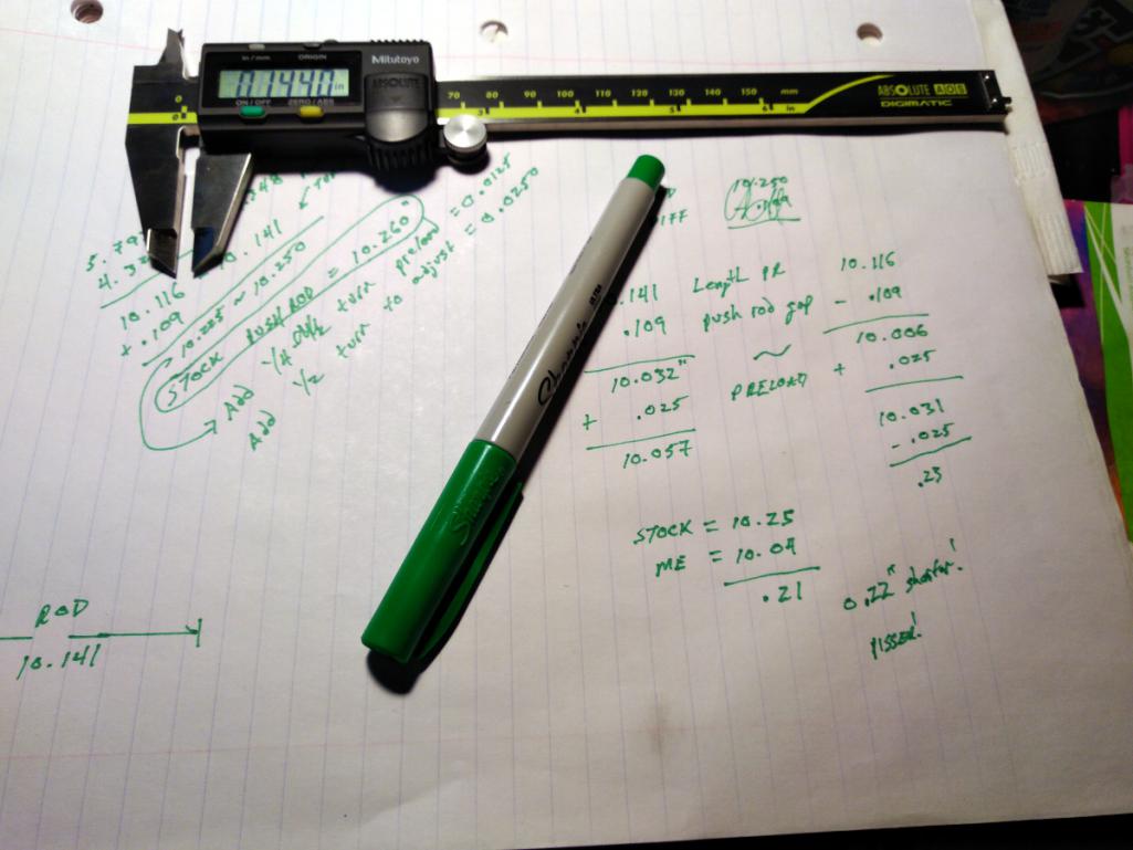
I'll sleep on it.
Posted by: Tbrown4x4 Jul 2 2018, 02:43 AM
Not sure I've ever seen a spec for the distance between the fan and the sheet metal. The critical measurement is the fan bearing flange to the top cover gasket surface. If that's right, the fan should be fine.
Posted by: worn Jul 2 2018, 08:26 AM
I'll sleep on it.
It's a hydraulic tappet isn't it? I never knew how those were measured, but thought that they pumped up when run. How does that figure in the calculations? I like the numbers and notes!
Posted by: HalfMoon Jul 2 2018, 09:12 AM
A few years back I got all excited about doing a Corvair engine conversion for my 1971 car. The project waffled. Numbers were crunched and chewed. Thought and diagrams and opinions were drawn out over long winter evenings.
One particularly rainy winter evening, I found an ad on Craigslist advertising a warehouse full of Corvair parts including engines. So my pal Rory and I drove a hundred miles into the boonies late one rainy night to what turned out to be an unmarked, geographically isolated, former slaughterhouse illuminated by a single 60 watt light bulb. No cell phone reception, no escape. We were met by a couple of toothless brothers who couldn't stop talking about Daddy. Seemingly they only did what Daddy wanted them to do. Daddy wanted them to sell the stash of Corvair parts. Daddy wanted them to steal my Toyota cargo van. Daddy needed to approve the transaction of cash for an engine. Daddy, it turned out, was long dead. The two brothers kept trying to separate Rory and I, and the creepier of the two brothers kept demanding my car keys so he could test drive my van, despite my insistence that it wasn't for sale. For the first time in a long time, I wish I had a tazer gun on me. The brothers eventually showed us exactly what I wanted - an RD code 1965 110HP engine. Fearing for our lives, Rory and I muscled the engine into the van while the brothers went to find more stuff for Daddy to sell to us, or you know, maybe a club or some rope or a ball gag or something.
I left the $100 on the bench and tore the hell out. Rory and I laughed all the way back to town, ever so pleased that we were neither killed, nor raped, nor eaten. Plus, we were one up on a Corvair engine.
So with a provenance like this, and seeing JRust's new car, Dr. Evil's project, and 914coops Nader's Nightmare all take shape I've finally decided to get serious about my own project: the VW-Porsche 914-C6.
The "C" stands for Corvair.
Odd off topic question. Can a set of Del 36's be used on a Corvair 140 engine? I looked around to see if anyone had done this and wasn't finding anything
Posted by: r3dplanet Jul 2 2018, 12:04 PM
As far as all the write-ups I've seen indicate, there shouldn't be any special consideration for the hydraulic lifters. But having said that, I've decided to go ahead and weld up a hydraulic lifter and re-do the measurements just to see if I can get a more accurate reading. Great question. Food for thought.
It's a hydraulic tappet isn't it? I never knew how those were measured, but thought that they pumped up when run. How does that figure in the calculations? I like the numbers and notes!
Posted by: r3dplanet Jul 2 2018, 12:13 PM
Do you mean the dual throat DRLA carbs? If so, then yes you can. You need a pair of custom manifolds that adapt the carb to the head. There are custom units out there for triple bore carbs, but I'm using Weber 40 carbs. Tom Knoblauch makes them at americanflat6.com. I have a photo back at the top of Page 8, post 141.
Basically you can make any manifold you want if you can TiG weld and have a mill. I don't have those but I know who does. For me it was an easy choice because I'm very familiar with Weber / Dellorto carbs.
Odd off topic question. Can a set of Del 36's be used on a Corvair 140 engine? I looked around to see if anyone had done this and wasn't finding anything
Posted by: Dr Evil Jul 2 2018, 07:45 PM
As far as all the write-ups I've seen indicate, there shouldn't be any special consideration for the hydraulic lifters. But having said that, I've decided to go ahead and weld up a hydraulic lifter and re-do the measurements just to see if I can get a more accurate reading. Great question. Food for thought.
It's a hydraulic tappet isn't it? I never knew how those were measured, but thought that they pumped up when run. How does that figure in the calculations? I like the numbers and notes!
The stock lifters are set to 0 and then tightened a specific amount....then you run the engine and adjust until quiet. No shit. Videos out there and special valve covers are sold or made. Its a mess to do, Ive done it.
As for roller rockers, go with a known source. I "saved money" from a guy that ended up not only selling cheap chinese crap, he sold the ones for a chevy V8 which have a different angle of attack. He promised they were correctly angled for corvair, I asked specifically. Well, check out my bus thread towards the end to see the destruction. The first one ate through the rocker stud and the others were not far behind.
Posted by: r3dplanet Jul 2 2018, 10:25 PM
An expensive cautionary tale. It still makes me angry. More so because that guy is still selling them.
The valve adjust videos are very cool. You slice a crappy valve cover down the long axis so it captures the oil (sort of) and then you tighten the rocker nut to quiet the valve. According to the book Performance Corvairs the best way to do this is as follows:
1. Set rocker distance to just touching (zero lash as Dr. Evil said).
2. Run the engine, and then on each rocker nut tighten until it quiets, or about 1/2 turn - which I found out yesterday with valve geometry is about .020".
3. Turn off the engine after all are completed and let it cool.
4. Give each valve another 1/8 turn.
I have some tooling being made up will get back to the geometry soon...
As far as all the write-ups I've seen indicate, there shouldn't be any special consideration for the hydraulic lifters. But having said that, I've decided to go ahead and weld up a hydraulic lifter and re-do the measurements just to see if I can get a more accurate reading. Great question. Food for thought.
It's a hydraulic tappet isn't it? I never knew how those were measured, but thought that they pumped up when run. How does that figure in the calculations? I like the numbers and notes!
The stock lifters are set to 0 and then tightened a specific amount....then you run the engine and adjust until quiet. No shit. Videos out there and special valve covers are sold or made. Its a mess to do, Ive done it.
As for roller rockers, go with a known source. I "saved money" from a guy that ended up not only selling cheap chinese crap, he sold the ones for a chevy V8 which have a different angle of attack. He promised they were correctly angled for corvair, I asked specifically. Well, check out my bus thread towards the end to see the destruction. The first one ate through the rocker stud and the others were not far behind.
Posted by: r3dplanet Jul 2 2018, 10:54 PM
... but first let's make a sandwich.
The process is easy for once. Clean the top of the engine case with acetone. Coat the first of two identical engine cover gaskets.
<shameless product placement>
I use Permatex High Tack in the spray bottle. It's my favorite gasket sealer because it's clean to use and has a long working time so I can relax and have fun. I wish Gasgacinch had a spray version also. But these two are very similar, even the same color and smell.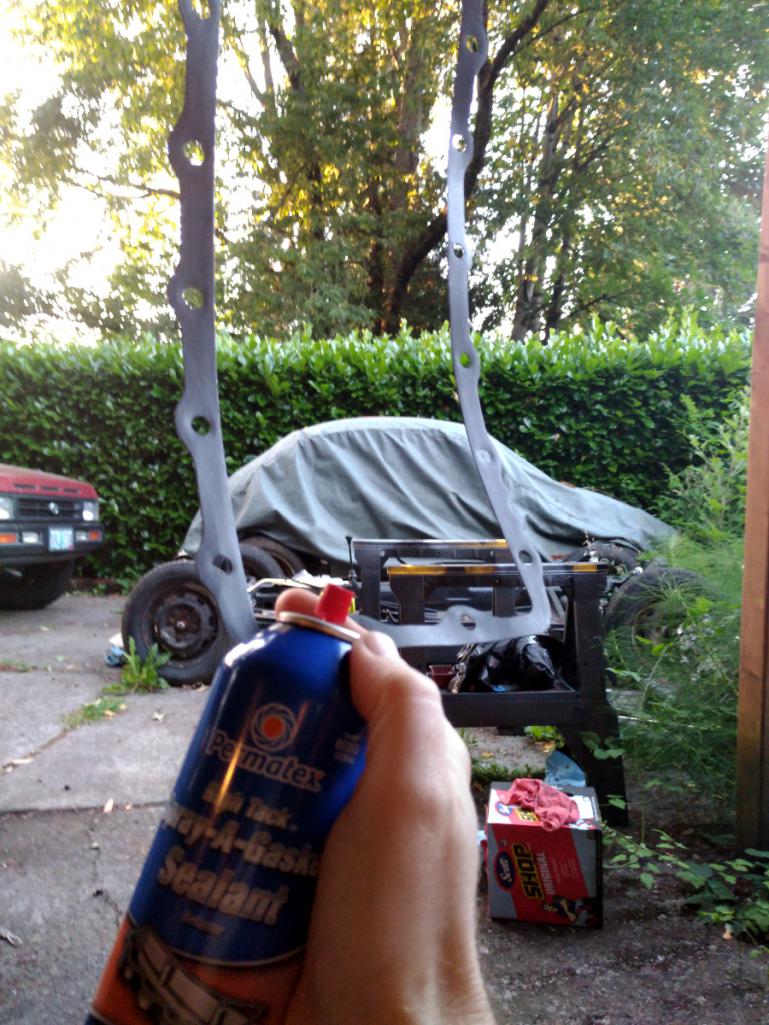
</shameless product placement>
Then add the baffle plate, the other coated gasket, and then the top cover. Like so: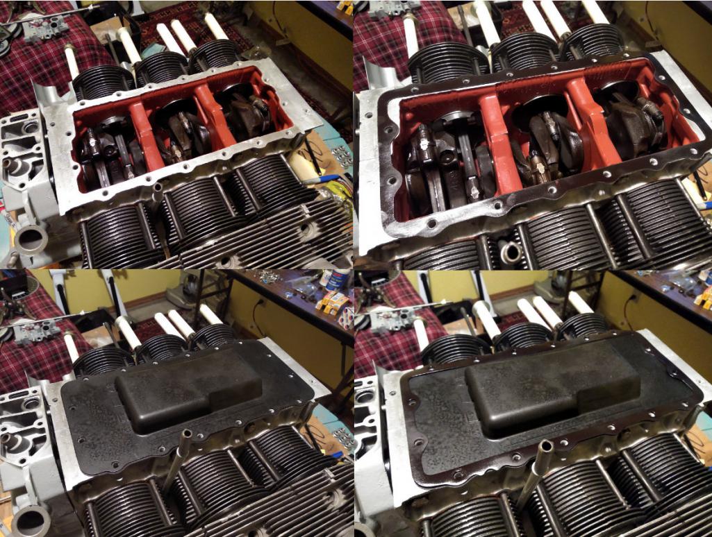
Finally just torque down all sixteen to 150 inch pounds after kissing each new bolt with a bit of JetLube. I went in three stages of 50 in/lbs until 150. I'm using stainless 5/16-18 x 1" bolts with lockwashers and washers. I don't want to besmirch the aluminum case.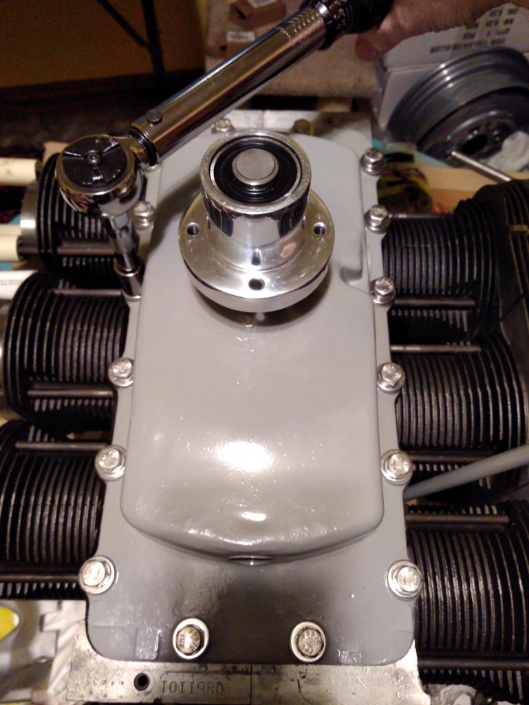
Here's the Dagwood all assembled. It feels a bit sad to not see the pistons any more. Not that I want to have a major problem and have to get back into it that far. Perish the thought.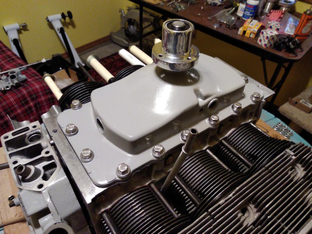
Posted by: Porschef Jul 3 2018, 04:24 AM
Awesome. Love the orange fan and pretty much everything else

Posted by: Dr Evil Jul 3 2018, 06:41 AM
... but first let's make a sandwich.
The process is easy for once. Clean the top of the engine case with acetone. Coat the first of two identical engine cover gaskets.
<shameless product placement>
I use Permatex High Tack in the spray bottle. It's my favorite gasket sealer because it's clean to use and has a long working time so I can relax and have fun. I wish Gasgacinch had a spray version also. But these two are very similar, even the same color and smell.
</shameless product placement>
Then add the baffle plate, the other coated gasket, and then the top cover. Like so:
Finally just torque down all sixteen to 150 inch pounds after kissing each new bolt with a bit of JetLube. I went in three stages of 50 in/lbs until 150. I'm using stainless 5/16-18 x 1" bolts with lockwashers and washers. I don't want to besmirch the aluminum case.
Here's the Dagwood all assembled. It feels a bit sad to not see the pistons any more. Not that I want to have a major problem and have to get back into it that far. Perish the thought.
I uses Great Stuff, which is more gooey. Ill have to try your stuff.
Posted by: r3dplanet Jul 8 2018, 08:41 PM
I like Permatex "Right Stuff" if I'm going metal to metal for sure. I've never tried is as a gasket sealant. Maybe I should.. 
I uses Great Stuff, which is more gooey. Ill have to try your stuff.
Posted by: r3dplanet Jul 8 2018, 08:59 PM
Okay. I'm doing little bits of this and this and that while I sort out two remaining issues - the oil pan and modified lifters for rocker geometry. Those will take a few days at least so it's time to work on pesky bits.
My attention has mostly been the Cover of Many Uses. It took quite a while to sand down the mating surfaces and lap them completely flat. I'm using my ever-handy flat glass plate and sandpaper. While in there, the 90 degree oil cooler connector is getting the same treatment.
Just to review, the Cover of Many Uses is a two-part assembly which houses the distributor, oil pressure sender, oil filler, mechanical fuel pump, and two oil bypass valves, one oil pressure regulator, and the oil pump spur gears. But it's getting a bit of a reprieve because I'm using an electric fuel pump instead of the mechanical one. Better all around.
The oil pump threw me for a bit of a loop. Here's the order of installation: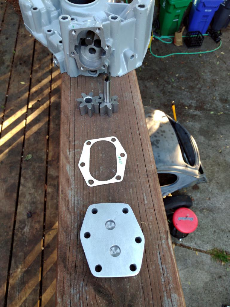
The clearance between the spur gears to the bottom plate is suppose to be .002-.003". Fair enough. The new oil pump comes with different size gaskets but none of them measured to nominal thickness. So a .010" gasket is really .0075". Great. I don't like Plasti-Gauge but this seems like an okay place for it. But no variant of gasket would get the correct clearance. Except for one, but when I twisted the drive gear with a screw driver to simulate the distributor gear, it rubbed against the bottom plate.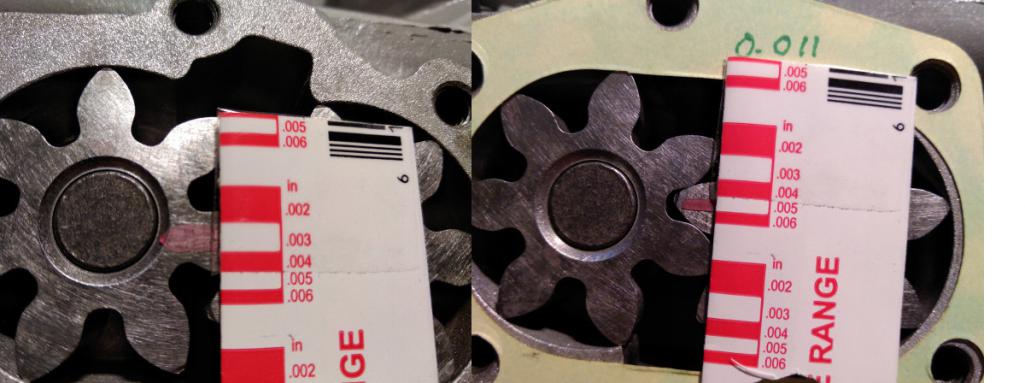
Further irritation came from the fact that use of feeler thickness gauges didn't match the Plasti-Gauge readings. Finally I realized that my NAPA-branded feelers were the wrong size! According to my micrometer, the .002 feeler is .007, and the .003 is .009. Lovely. I have a nice Mitutoyo set on order.
The last bit of despair came when I measured the original oil pump gears with the new ones. As you can see, the new ones are .798-ish, but the old one is dead nuts on .800". The service manual says GM will happily provide oil gears in increasing thicknesses of .001" to get the correct fit, but those are long gone. I called the parts vendor and the guy measured some on the shelf and said, "yeah, they're all like that."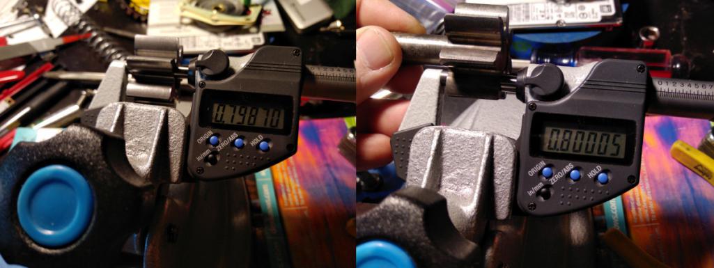
Right. So I have another oil pump coming from Melling, and maybe it will be the right size. Normally I wouldn't squawk but oil pump clearances are critical.
Posted by: r3dplanet Jul 8 2018, 09:10 PM
Moving along, I spent some time polishing the 90 degree oil cooler adapter that connects the engine case to the oil cooler. In the future I'm positive that it will get changed to a remote oil cooler, but this will certainly work well enough for now.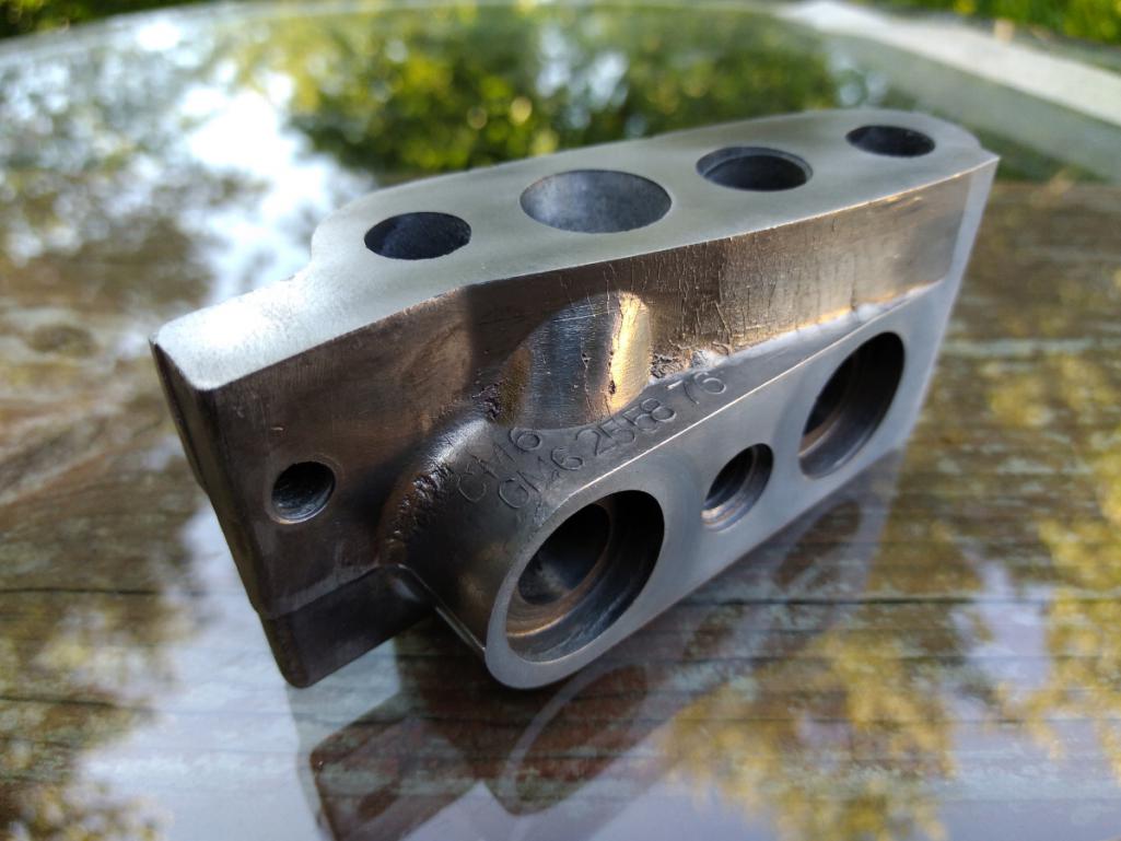
Then I went to powder coat it and some other parts, but made the unpleasant discovery that the only colors I have left on my shelf are Ford Blue, Chrysler Orange, and chrome. So chrome it is! As you can see, the finished product is really trashy. I have no idea where the bubbles came from, especially after cleaning it so well. Now it looks awful, but I don't care enough to strip it and re-coat it.
Ta da! Professional results every time when yours truly is involved!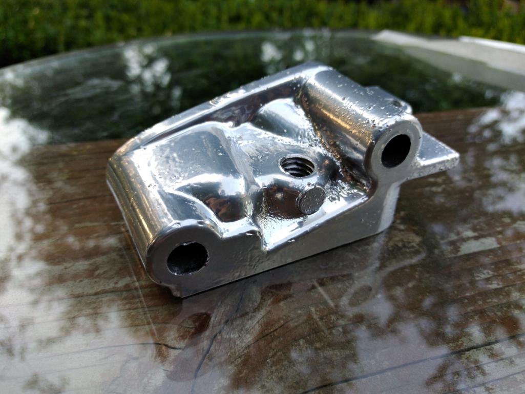
And then the PCV tube and clamp. Note that the tube installs with a little Viton o-ring. Then it's clamped into place. The top of the tube pokes through the engine shroud and then to ... I'm not sure. A PCV valve for sure, or maybe a filter-to-carb adapter. Something. I've heard it whispered that a Volvo PCV valve is exactly the right size. We'll see.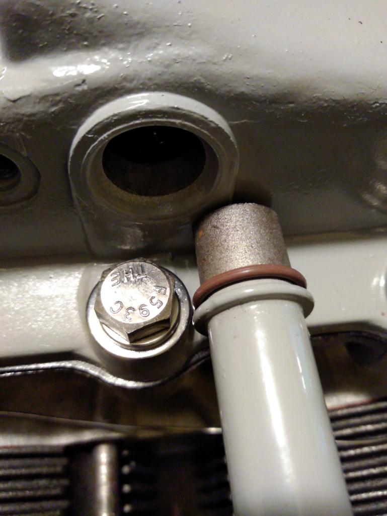
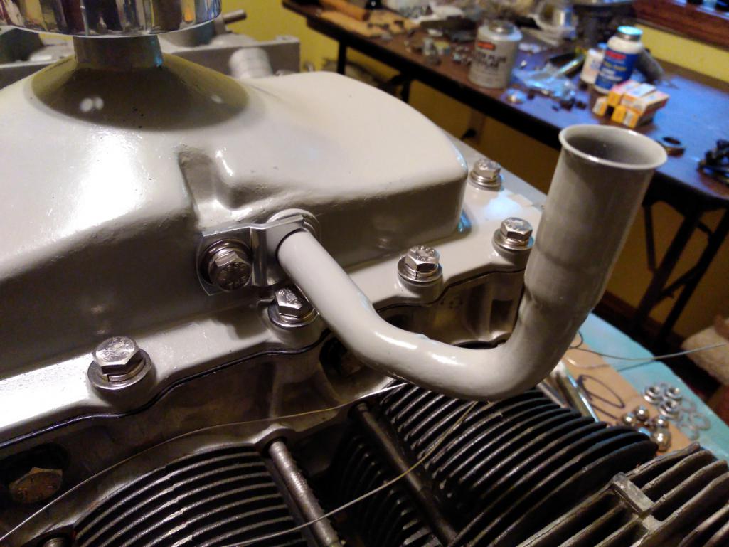
Posted by: r3dplanet Jul 8 2018, 09:15 PM
A quick note on the cylinder heat shields. They sit underneath and would normally clip into place if the stock cylinders are used. Since these are not stock cylinders, I'm using stainless wire. Not classy, but it works.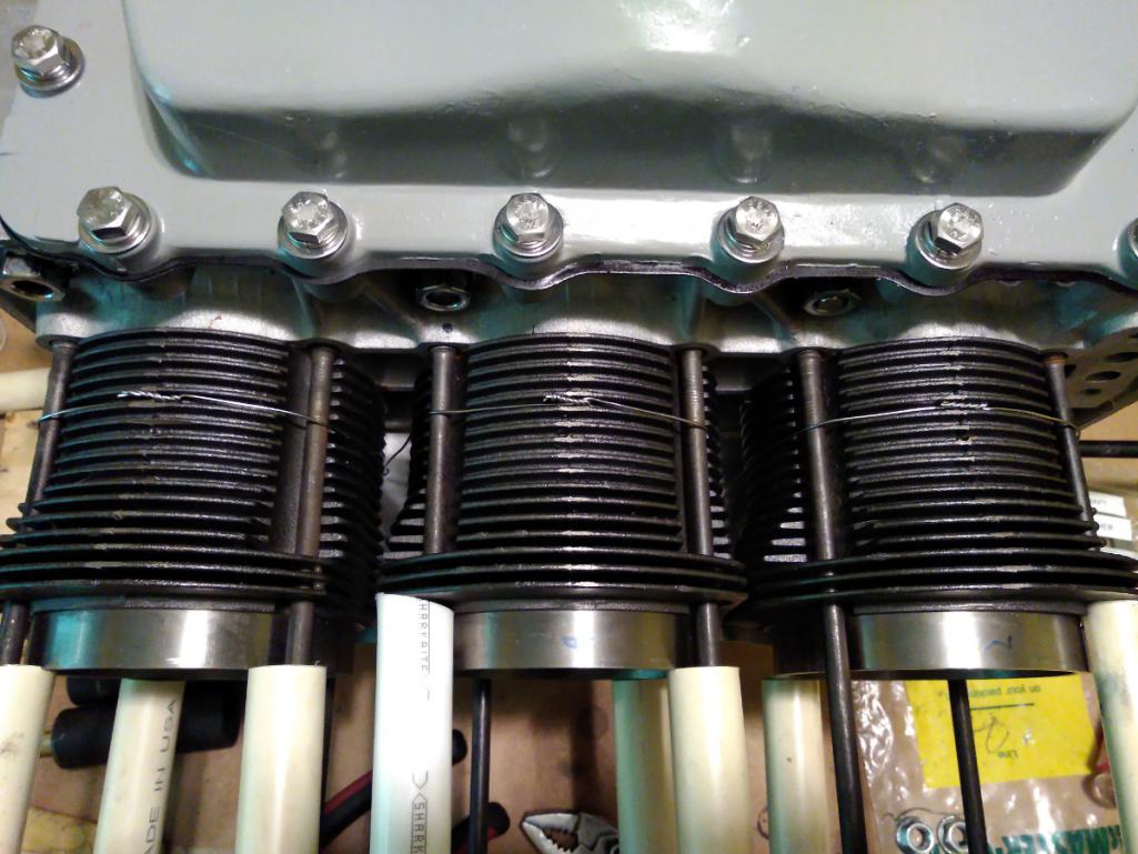
Posted by: r3dplanet Jul 8 2018, 09:55 PM
In modern times, whenever the word "EMPI" gets involved I get a little nervous. So it was again when I went to install the other cylinder head. The thickness of the copper head gaskets are supposed to be .040, but .035-.040 is fine. As long as they all match, right? Here's the current collection of head gaskets: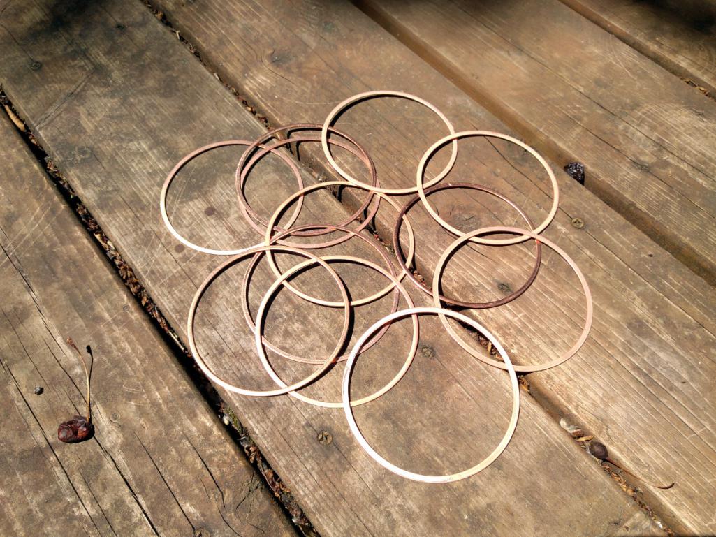
Because the step has been removed from the heads and opened to 94mm, we're using 94mm head gaskets. But I quickly found that these gaskets ranged in thickness from .034-.047. They don't compress so it's a big deal to have the right thickness. In one of the packs I bought it contained, weirdly, a 90.5mm gasket and three 92mm gaskets. Right. After visiting my local VW shop this morning I bought yet another package. And this time each gasket was perfect - 94mm, .039 thickness. So it's a little example of how EMPI can make great parts, but with quite a lot of variation.
Then came a moment of panic when I went to trial fit the other cylinder head. It installed correctly but then the engine wouldn't turn over . W T F..>?
After removing the head and doing what I should have done before in terms of quality control, the problem immediately became clear. I accidentally used one of the 92mm gaskets and it disallowed one of the pistons to fully rise. This was the point where I re-measured all of them.
Once that was cleared up I moved to mocking up the second cylinder head. Observe that the heads are held onto the cylinders by way of six nuts on the top row, and six threaded studs on the bottom row. The top studs must be flange nuts. If just a standard washer is used instead the washer will bow out and become wiggly. To help prevent rust (remember the work where I had to use a nut cracker on each of these during disassembly?) I'm coating each stud with JetLube, torquing on the flange nut, and then installing an acorn nut to protect the threads. I splurged and bought 316 stainless fasteners from McMaster.
The bottom row holds the head down with dual-purpose studs. That is, it holds down the head but it also provides a stud to which the rockers are mounted. I spent some time cleaning each of the internal and external threads on these. They are hardened steel. Here's one goobered in JetLube.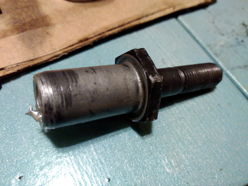
These require no special treatment for oxidization like the top row because they're always coated in oil instead of being exposed to the atmosphere.
This is the time where I tighten up my girdle. The pushrods rest in holes positioned on the pushrod guides, one per valve pair. Note that the "U" is only on one side and faces "You." U for You. Like an '80s Danish band name.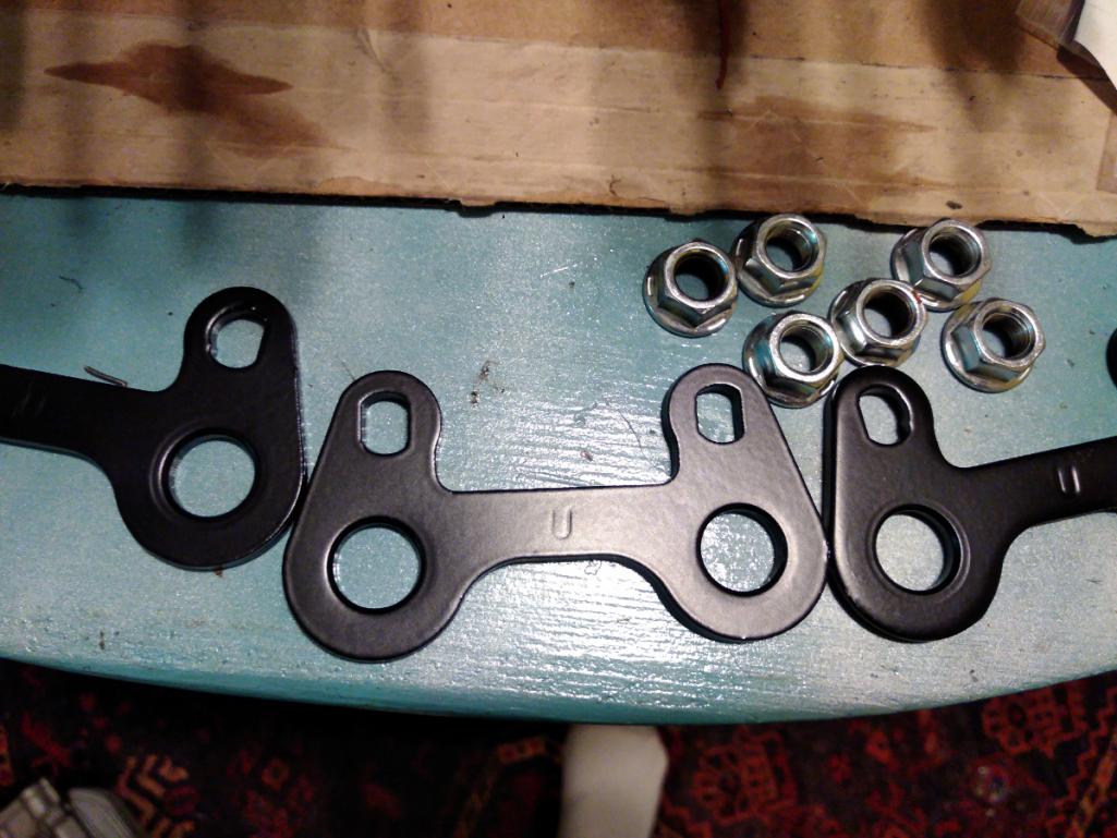
Very important note: The service manual says to torque the head nuts down to 38-40lbs, but that's way too high. That amount of force can pop out the case stud and then it's a Very Bad Day. Because the JetLube I use is messy and very slippery, I'm torquing the top nuts to 30 ft/lbs and the bottom row to 32 ft/lbs. I can always bump it a bit if necessary.
I don't have the lifters or pushrod tubes installed yet because I'm waiting to do the rocker geometry. But here's what it looks like when mocked up.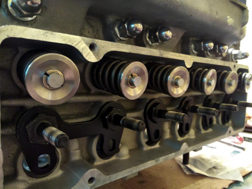
Posted by: r3dplanet Jul 8 2018, 10:06 PM
Just a few last notes for now.
I'm doing some passive work by soaking the lifters in some 30 weight dino oil. It isn't necessary but it makes me feel like things are still moving even when I'm down for a few days. This humble can normally contains the best coffee ever made. Admittedly I'm not a huge coffee drinker, but I'll lay this dead bird at your feet: if your opinion differs you should reflect on your coffee choices over long winter evenings.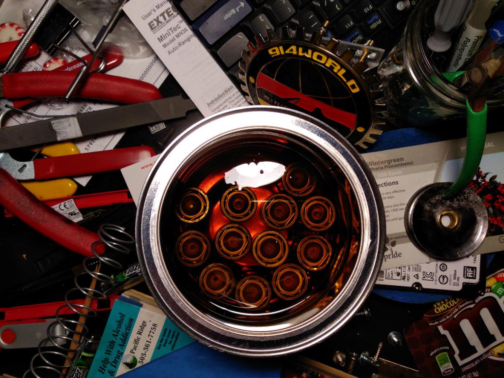

And here's the engine as of today. I'm running out of parts to assemble. Rad!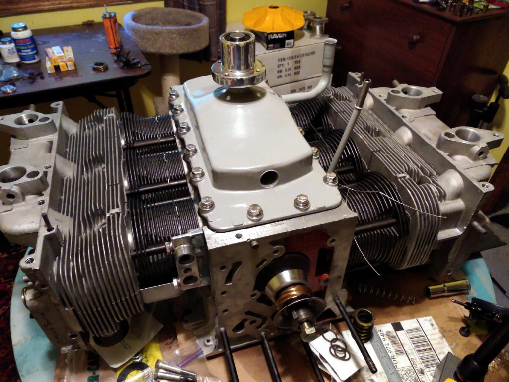
Posted by: Tbrown4x4 Jul 9 2018, 03:00 AM
You did get the small o-rings under the rocker studs (nuts?). right?
The engine's looking great! I can't wait to see how it fits in the car.
Posted by: Vacca Rabite Jul 9 2018, 07:16 AM
For the oil pump housing thats .002 too deep, here is what Jake told me to do a bunch of years ago. Took a little time but it worked.
Take a pane of glass and put some fine grade sandpaper on it (I used 800 grit). Using a good bit of oil, use that to slowly mill down the pump housing. Test periodically so that you don't accidentally take too much off. Doing this will get you exactly how much clearance you want at the oil pump.
Zach
Posted by: r3dplanet Jul 9 2018, 11:25 AM
Good point!
I didn't put them in now as it's just a mock up to make sure the crank can spin. I'll be sure to detail the proper install sequence when I have everything else ready. Thank you for pointing that out.
You did get the small o-rings under the rocker studs (nuts?). right?
The engine's looking great! I can't wait to see how it fits in the car.
Posted by: r3dplanet Jul 9 2018, 11:28 AM
Hey Zach,
Thanks for saying this. The new pump should arrive today, but if it's not the right size I'm going to have to get creative. This process sounds like a good way to get it dialed in.
For the oil pump housing thats .002 too deep, here is what Jake told me to do a bunch of years ago. Took a little time but it worked.
Take a pane of glass and put some fine grade sandpaper on it (I used 800 grit). Using a good bit of oil, use that to slowly mill down the pump housing. Test periodically so that you don't accidentally take too much off. Doing this will get you exactly how much clearance you want at the oil pump.
Zach
Posted by: 914forme Jul 9 2018, 08:56 PM
For the oil pump housing thats .002 too deep, here is what Jake told me to do a bunch of years ago. Took a little time but it worked.
Take a pane of glass and put some fine grade sandpaper on it (I used 800 grit). Using a good bit of oil, use that to slowly mill down the pump housing. Test periodically so that you don't accidentally take too much off. Doing this will get you exactly how much clearance you want at the oil pump.
Zach
And if you want to start making reeds for woodwind instruments you can use the same technique minus the oil.
Posted by: Larry Hubby Jul 9 2018, 09:27 PM
Hi Marcus,
Beautiful work on your build! A lot of what you're doing is very familiar to me because I was originally (back in ~1980) going to put a built Corvair in my 914 using much the same parts you seem to be using now. I had multiple cars, engines and parts, and my wife thought I was running a used car lot. I ultimately fell into the opportunity to buy a '78 911SC engine and trans, and went that direction instead, giving all my Corvair stuff away to a friend.
I do remember some of the issues with a reverse rotation engine, however, one of which was that you have to reverse the louvers on the crankcase baffle, otherwise the spray from the crank will pump oil out the breather because the louvers face the wrong way and you can't simply reverse the baffle plate front for back to fix it because the cover bolt pattern isn't symmetrical. Perhaps you're well-aware of this and have done something about it, but I didn't see any reference to that in your thread, and I'd hate for all that beautiful work you've done to run afoul of something so simple.
Regards,
Larry Hubby
Posted by: r3dplanet Jul 9 2018, 11:03 PM
Wait, WAIT...
First up, I'm super pleased to have you here on this thread. It would be great if you could tell us more about your project, even though it's gone. I'll bet that you're full of good information.
Second,
I'm 100% unaware about flipping the baffle plate. As far as I knew it only fit on one way, the stock way. I've read in the books that the main thing is to make sure that the PCV tube is mounted on the opposite side of the baffles. I haven't read anywhere about about this. Could I persuade you to maybe give a bit more detail and depth on this? I want to make sure that I understand.
Also, what did you do on your car about the thermostats and cooling flaps? On the Corvair, they point directly aft of the car. I'm not super sure how to tackle this but figured I would spend some brain power when the time came.
Welcome aboard!
Hi Marcus,
Beautiful work on your build! A lot of what you're doing is very familiar to me because I was originally (back in ~1980) going to put a built Corvair in my 914 using much the same parts you seem to be using now. I had multiple cars, engines and parts, and my wife thought I was running a used car lot. I ultimately fell into the opportunity to buy a '78 911SC engine and trans, and went that direction instead, giving all my Corvair stuff away to a friend.
I do remember some of the issues with a reverse rotation engine, however, one of which was that you have to reverse the louvers on the crankcase baffle, otherwise the spray from the crank will pump oil out the breather because the louvers face the wrong way and you can't simply reverse the baffle plate front for back to fix it because the cover bolt pattern isn't symmetrical. Perhaps you're well-aware of this and have done something about it, but I didn't see any reference to that in your thread, and I'd hate for all that beautiful work you've done to run afoul of something so simple.
Regards,
Larry Hubby
Posted by: r3dplanet Jul 9 2018, 11:26 PM
Ugh. More oil pump drama today. I spent a week waiting for a "new" Melling oil pump to arrive from California. I figured it would be NOS in any event since nobody makes them any longer, except for Clark's, and theirs is mostly worthless. On the subject of the Clark's oil pump, not only is it .0015-.002" too short, but I measured the backlash today and there isn't any. Zero. It would bind for sure if installed. I perused some of the Corvair forums and found that numerous other buyers had the same problem going back at least three years. Great.
I sat around all day waiting for the new pump because they send signature required only. So I lost half a day waiting around. And to my surprise in the box was a s#itty oil old pump. In was in the NOS Melling box, but very poorly packaged. The gaskets were bent up and the gears were obviously used and worn. The driveshaft shows scoring and the gaskets have grease on them. Have a look: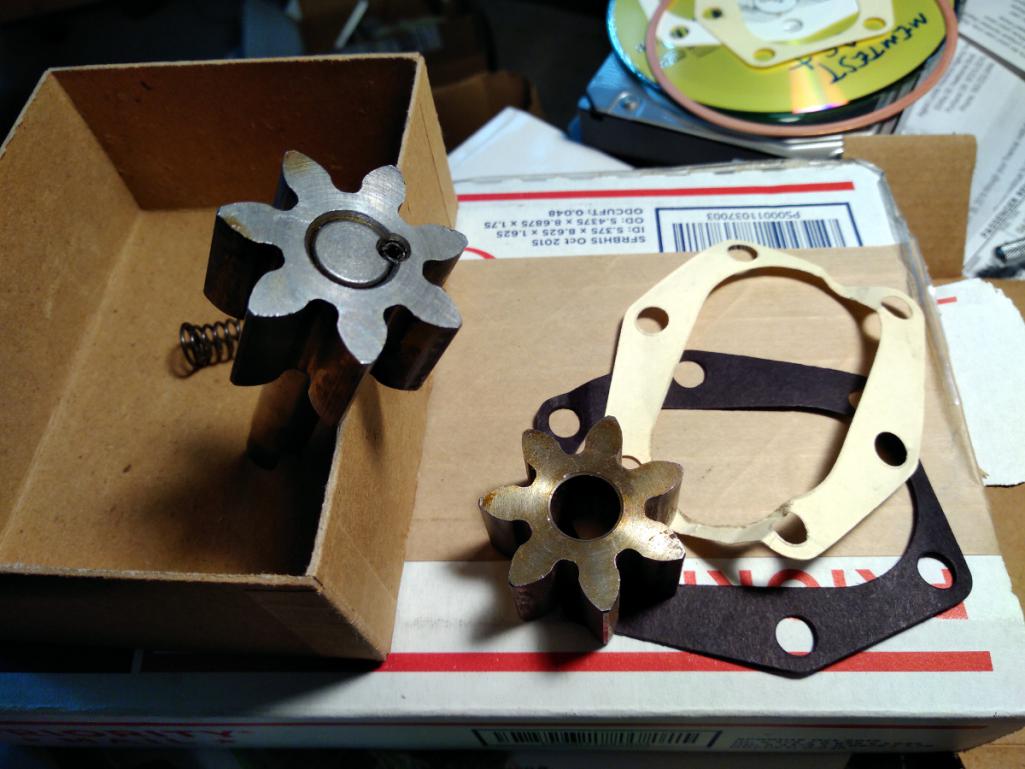
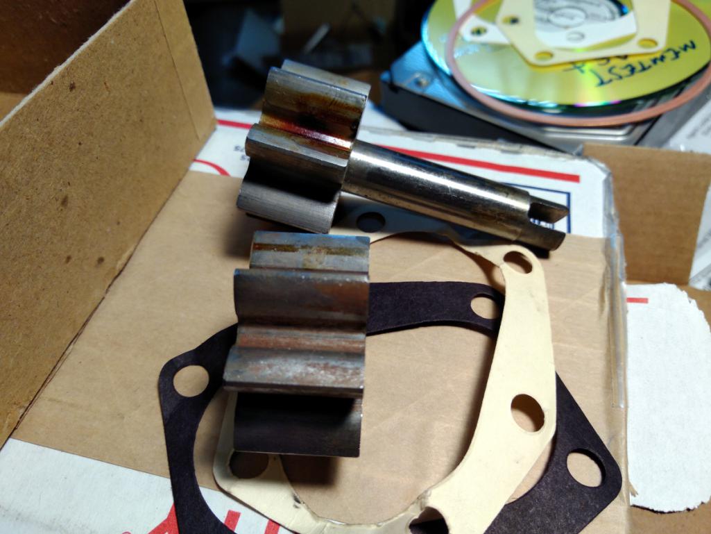
Also, it's worn down so far that the backlash is out of spec. So this too is worthless.
I contacted the vendor and was told again that they've sold many of them and insist that it's new. They made no mention of it being used, worn, or trashed. And obviously didn't even open the box before they shipped it.
<rant>
I'm getting tired of this "that'll do" attitude on the part of some vendors. I do understand that much of these parts are long gone, but I hate having my time wasted by someone else's laziness. The customer is not in charge of quality control.
</rant>
But one silver lining came of it. Playing around with the Clark's oil pump and my original oil pump, I found that by using the out-of-spec Clark's drive gear and my original idler gear that I can get mostly decent measurements. It's not perfect splitting the differences like this, but I am getting .003" clearance to the cover and .004" backlash, which is supposed to be between .002-.008".
Once mocked up it span very well and with proper gap. But then one last bit of bad news: having torqued on the cover so many times over the past week I managed to strip one of the threads even though I was only going to seven foot pounds. No biggie. I'll pop a big-sert into tomorrow.
I'm relieved that all this ridiculous oil drama is over. What a pain. Time to move on.
Posted by: Dr Evil Jul 10 2018, 01:35 PM
Ugh. More oil pump drama today. I spent a week waiting for a "new" Melling oil pump to arrive from California. I figured it would be NOS in any event since nobody makes them any longer, except for Clark's, and theirs is mostly worthless. On the subject of the Clark's oil pump, not only is it .0015-.002" too short, but I measured the backlash today and there isn't any. Zero. It would bind for sure if installed. I perused some of the Corvair forums and found that numerous other buyers had the same problem going back at least three years. Great.
I sat around all day waiting for the new pump because they send signature required only. So I lost half a day waiting around. And to my surprise in the box was a s#itty oil old pump. In was in the NOS Melling box, but very poorly packaged. The gaskets were bent up and the gears were obviously used and worn. The driveshaft shows scoring and the gaskets have grease on them. Have a look:
Also, it's worn down so far that the backlash is out of spec. So this too is worthless.
I contacted the vendor and was told again that they've sold many of them and insist that it's new. They made no mention of it being used, worn, or trashed. And obviously didn't even open the box before they shipped it.
<rant>
I'm getting tired of this "that'll do" attitude on the part of some vendors. I do understand that much of these parts are long gone, but I hate having my time wasted by someone else's laziness. The customer is not in charge of quality control.
</rant>
But one silver lining came of it. Playing around with the Clark's oil pump and my original oil pump, I found that by using the out-of-spec Clark's drive gear and my original idler gear that I can get mostly decent measurements. It's not perfect splitting the differences like this, but I am getting .003" clearance to the cover and .004" backlash, which is supposed to be between .002-.008".
Once mocked up it span very well and with proper gap. But then one last bit of bad news: having torqued on the cover so many times over the past week I managed to strip one of the threads even though I was only going to seven foot pounds. No biggie. I'll pop a big-sert into tomorrow.
I'm relieved that all this ridiculous oil drama is over. What a pain. Time to move on.
I remember the oil pump being one of the biggest PITA of the whole build. IT still leaks, but at this point I don't care. I will remove the engine someday and go over it to address issues that are revealed.
I think the Corvair vendor attitude, and the AC VW guys as well, of "Eh, its good enough" is due to the fact that most are not building to your level of build and just slap on the part and go and it usually provides enough service to not be an issue. A shame.
Posted by: r3dplanet Jul 10 2018, 02:45 PM
I agree. I understand that I'm being a bit exacting about tolerances and quality. At some moments it's a big deal, others not so much. I hate complaining about this stuff. I need to understand that these engines went out of fashion long ago, but so did the Beetle or the 914. As I'm sure we can all attest some aftermarket vendors are great and others not so much. It's one of the things that really draws me to the 914 crowd, because so many people here are going out of their way to produce necessary parts at a high level of quality. That's such a huge benefit for us.
Little updates: I finally found a machinist who will flatten the oil pan and valve covers and that should be finished within days. After that I can install the lifters and then do the rocker geometry. Soon there will be a point where the rebuild will finish and fitting the engine will become the goal.
But I'm also rapidly running out of time. I'm trying to get this all buttoned up and sold before the end of August.
What do you guys think? Since my goal is to sell my precious 914 to some lucky and intrepid gentleman, should I proceed with fitting the Corvair engine and try to sell it? Or install the 1911cc Type-4 and appeal to a wider market? Time is running short and soon another pair of hands is going to have to pick up where I left off. Or at least that's my hope.
More soon.
[/quote]
I remember the oil pump being one of the biggest PITA of the whole build. IT still leaks, but at this point I don't care. I will remove the engine someday and go over it to address issues that are revealed.
I think the Corvair vendor attitude, and the AC VW guys as well, of "Eh, its good enough" is due to the fact that most are not building to your level of build and just slap on the part and go and it usually provides enough service to not be an issue. A shame.
[/quote]
Posted by: sixnotfour Jul 10 2018, 06:41 PM
follow your dream,,my dad built a 911 wheelbase corvair, then wanted to put it a 914, he then passed away,, I parted the corvair out...quick box ,saginaw gearbox, tele wheel column , 140 plus with tripple webers.. follow your dream ...the rest does not matter...God Bless
Attached image(s)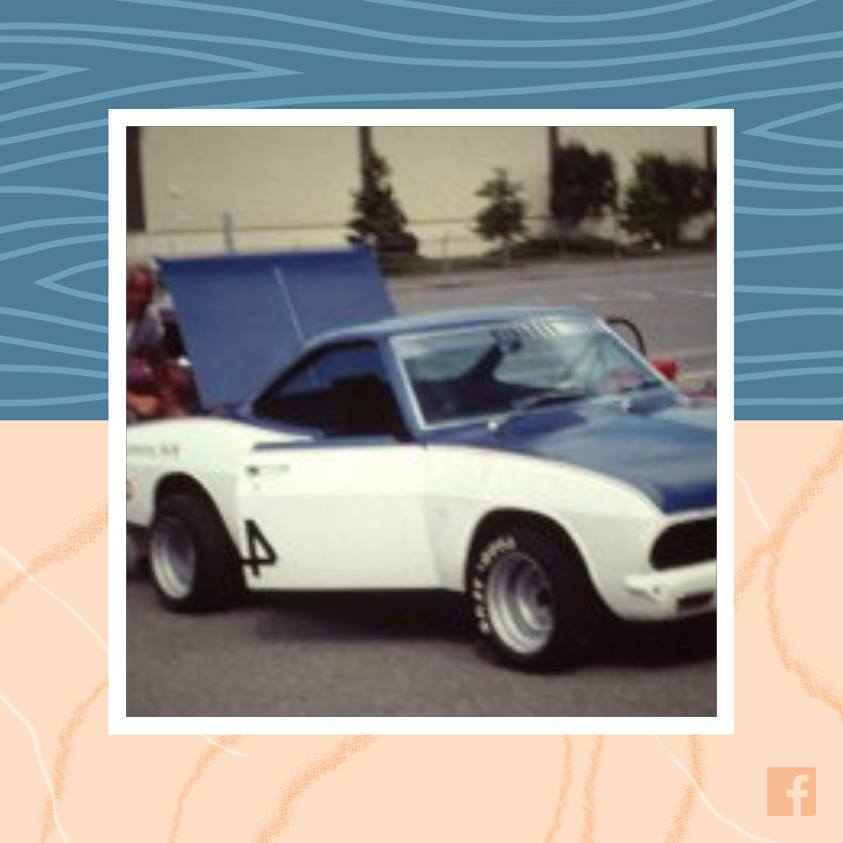
Posted by: worn Jul 10 2018, 08:39 PM
I have had your thread open in a tab for weeks. Such grace and finesse. We could all benefit from what you are doing. Thanks Marcus. Were it me, as surely it will be in some way, I would forget about end goals and do what makes you happy now. How wise that advice might be beats the heck outa me.
Warren
Posted by: Larry Hubby Jul 10 2018, 09:28 PM
Hi Marcus,
I believe the baffle plate does fit only one way. The bolt holes, although they look close to symmetric fore to aft, aren't quite, and you also need, as you said, to keep the sloped side of the top part of the baffle toward the breather pipe. What I remember was that you had to literally reverse the louvers by hammering them into the baffle plate. You use a punch and a hammer to hit the center of the louver and get it started, then you can bend down the remainder of it with the blade of a screwdriver. Not pretty, but it keeps the oil in the crankcase where it belongs.
As far as my experience being very useful on your project, I never got my engine in the car, or even assembled, so it's highly questionable. I did build a front motor mount to fit it in the car, but never got to try it, so I'm not sure it worked. You certainly seem to be using good parts. The Otto Parts oil pan and cam gear retainer, the Crown transmission adapter, the nitrided crank, 140hp heads, etc. are all the good stuff. One thing I'm not sure about is using dual throat Weber carbs on 140hp heads. The second carb on each side of the stock 140hp setup was opened progressively and so was like the secondary barrels of a four-barrel single carb. My understanding was that this was done due to flow reversals in the intake runner that are quite pronounced under part throttle conditions. The center-mounted adapters for four barrel carbs that were popular for the Corvair had baffles that confined flow from the primary throats to the ports at the rear of the engine (in a Corviar), and the secondaries to the front ports. This was correct for one side of the engine, but not the other, and these things never worked very well if I recall correctly, and machining out the baffle made them work even worse. So, if the Webers open both barrels at the same rate, you might experience some rough running at low to medium throttle openings. If you have a copy of Bill Fischer's book, "How to Hotrod Corvair Engines", I beleive this effect is talked about in it. Crown Engineering had at one point some manifold adapters that fit the triple-throat Webers used on the 911 engines on the Corvair heads. You had to machine off the intake runners to mount them so that you had a true individual throat of carburetion per cylinder configuration, and of course the carbs are quite spendy, but it worked very well. No idea if such things are still available.
Regards,
Larry Hubby
Posted by: r3dplanet Jul 10 2018, 10:15 PM
Cool photos! Thanks for sharing them here for us all to see.
In the past I've followed my dreams to mixed results, but that's the way it always works out. Before I got sick there was always plenty of time to plan adventures. There was always something to do next year, something of which to look forward. Way back when I worked for the government it was great because I was always jetting off somewhere, and when that wasn't in play I was eating up time at grad school. I loved all that. The sense that something is always coming down the pipe.
But cancer changes that because it removes the possibility of planning anything. So really it's all about what's happening in the next few days, punctuated by a full medical calendar. Sometimes time passes so slow when relatively healthy, but now the months are ripping off the calendar. And so it is that the dream chasing period has ended and the quest for creature comforts and stability is the most important thing. On a long enough timeline that's how it works for most people. It's just that I'm hitting it sooner rather than later. So whether I like it or not, it's time to sell of my toys and let someone else play with them.
Those photos of your dad? He looks like he's having a blast.
follow your dream,,my dad built a 911 wheelbase corvair, then wanted to put it a 914, he then passed away,, I parted the corvair out...quick box ,saginaw gearbox, tele wheel column , 140 plus with tripple webers.. follow your dream ...the rest does not matter...God Bless
Posted by: r3dplanet Jul 10 2018, 10:22 PM
Warren, thank you for the kindness.
I feel like I'm already dumping out my purse for everyone to see. But yes, it's all about the now and soon rather than long term. I promise you I'm not graceful in any meaning of the word. Instead, I've just had way too much time to adjust. Long ago when I was living in Moscow as a student I overheard some babushkas at a magazine stand gossiping about Yeltsin, who was on his way out of both power and lifespan. The phrase always stuck with me, even though I can't now conjure the Russian translation. The woman said, "Yeltsin! Always dying but never dead!" The idea being that it's super bad manners to take more time than you really need. Now I really understand that. Gulp.
When it was my turn at the stand, I bought an orange Fanta and a Playboy. The nipples on Russian Playboy pinups are airbrushed out, just FYI. How's that for graceful?
I have had your thread open in a tab for weeks. Such grace and finesse. We could all benefit from what you are doing. Thanks Marcus. Were it me, as surely it will be in some way, I would forget about end goals and do what makes you happy now. How wise that advice might be beats the heck outa me.
Warren
Posted by: r3dplanet Jul 14 2018, 08:30 PM
Alright. The oil pump is finally finished. It took way, way more work than I wanted but it's all assembled now. The solution ended up being a little Column A, a little Column B. Using my flat glass plate I ground down .001" off the original oil pump idler gear in order to make it the same depth as the new drive gear. Then I polished and polished and polished both mating surfaces and went through a dozen gaskets getting it all just right. Or at least I think it's right. Doubt is a devil.
I also fixed the both stripped threads on housing side using Time-Serts, which are my favorite insert - especially for jobs like these with tiny clearances. Anyway, the oil pump is finally finished. Hoo!
You may have noticed that the oil pump cover has two holes in it. This is an aftermarket cover sold by Clark's, and if desired, can be purchased with much longer oil pump gears for high pressure applications. Those gears have a shaft that would fit into these bores. I left the doors open to the possibility for this later if the engine ends up with both a remote cooler and filter. But it might not be necessary. I understand that high pressure does not equal high volume, but I'm not a fluid dynamics expert.
Crappy focus, good thread repair: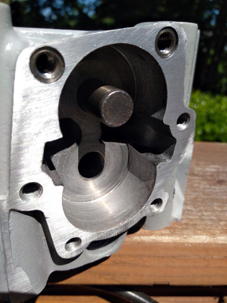
Somewhat polished: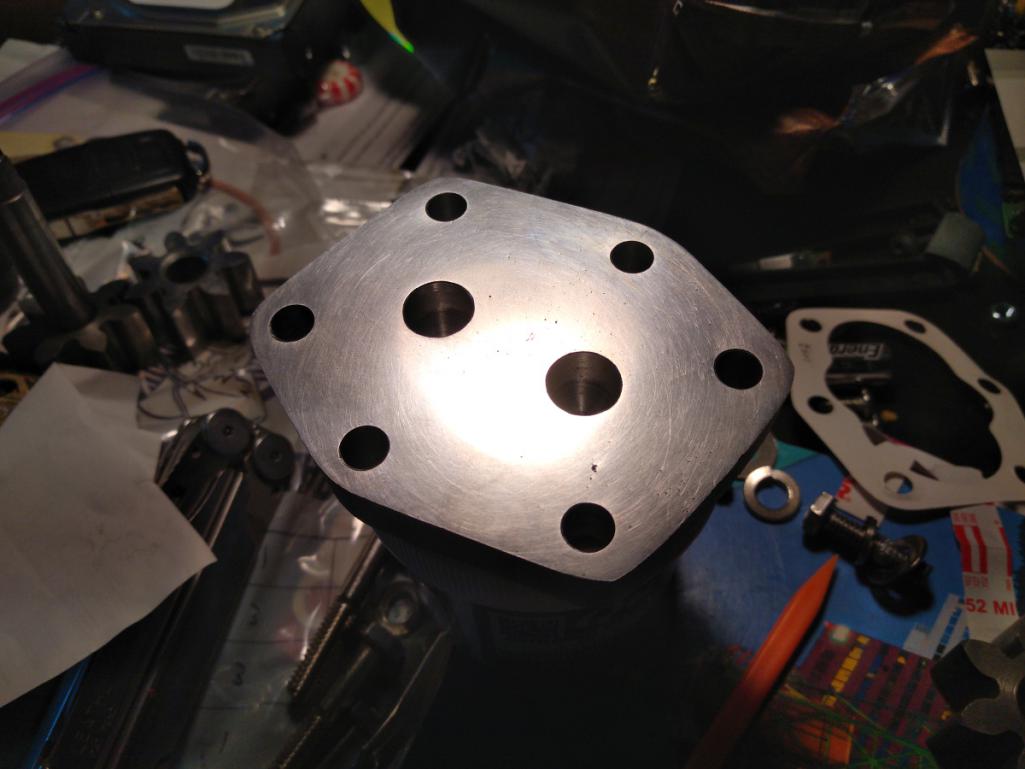
Posted by: r3dplanet Jul 14 2018, 09:02 PM
Also finished is the Cover of Many Uses. This was a surprisingly long side project, but if I had more experience I would be less surprised. Experience > surprise.
It didn't help that I did all the work out of order. If there was to be a next time, I would do it in this order:
First, prep all the mating surfaces by which I mean find any means necessary to make them flat and clean. There are many of these surfaces on the cover. The big one is the rear side of the cover where the the oil channels are and where it mates to the engine case. This photo shows a step during the polishing phase, again using my big glass plate and increasingly finer sandpaper. Because I'm physically weak, this really sucked.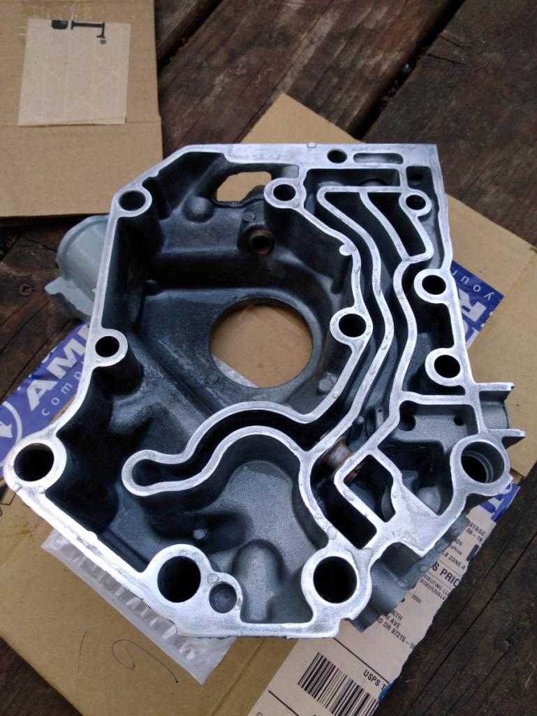
I noticed that the oil pressure valve was a little sticky because the valve itself is a spring loaded tube, but the bore was rough from the original casting. So I made a ghetto polishing tool for which I'm finding ever more uses. It's a screwdriver surrounded by Scotchbrite. Below I'm checking for smooth operation by means of another screwdriver.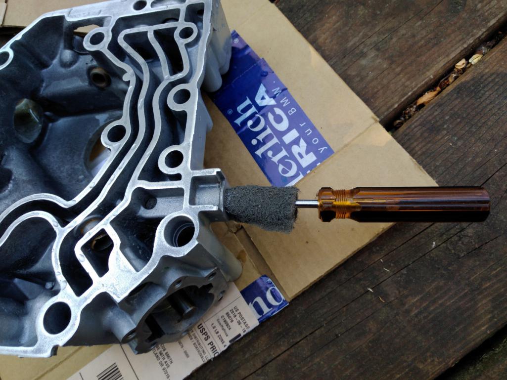
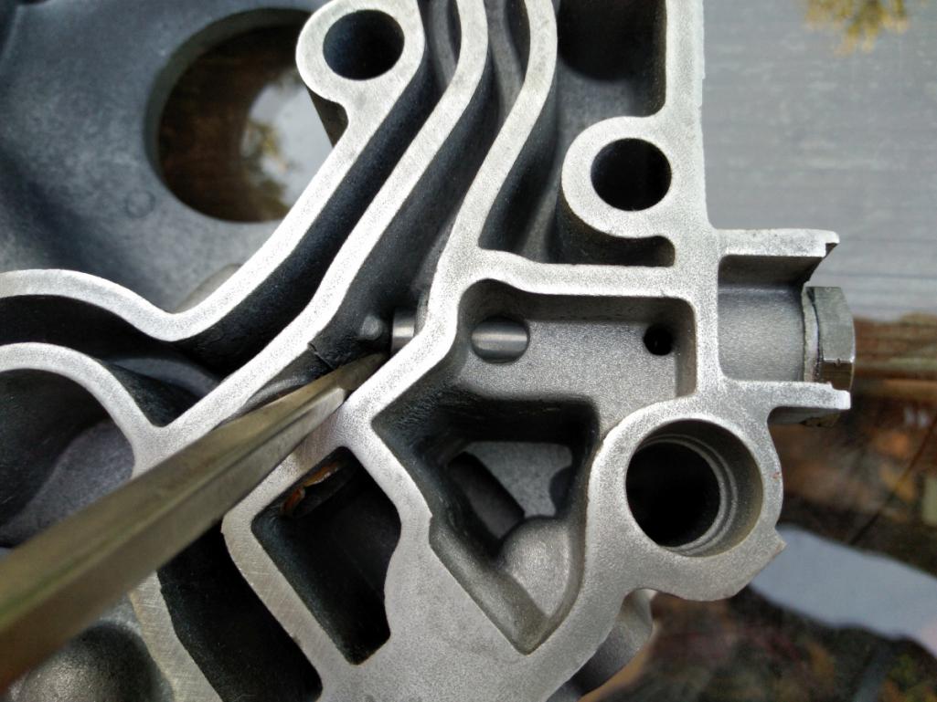
Easier to polish was the front mating surface for the soon-to-be installed seal.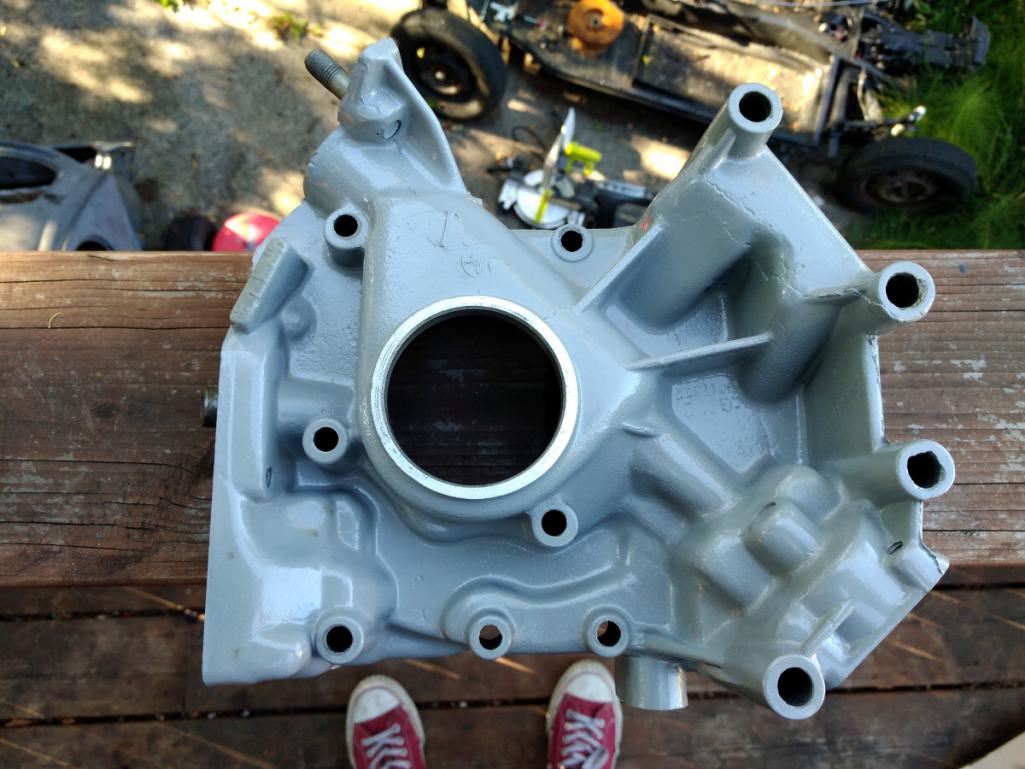
The Cover of Many Uses has two parts, upper and lower. The large lower section makes a home for the distributor, oil pump, fuel pump rod, oil pressure valve, and one of the two oil bypass valves. The smaller upper section is the home for the oil pressure switch, fuel pump, and oil filler tube.
On my cover, these two mating surfaces did not match well. There was a .020" rock from one diagonal side to the other. It wouldn't have been so bad to sand them flat except that this steel fuel rod tube is in the way. Sadly, I don't even need it because I'm using an electric fuel pump. I tried to tap it out but it didn't want to budge without heat, and since I already powder coated it torching it was out of the question. I pulled out a blue sharpie and sanded and matched over and over seemingly forever until it finally squared up.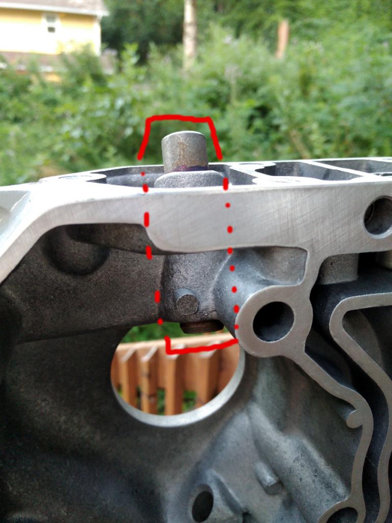
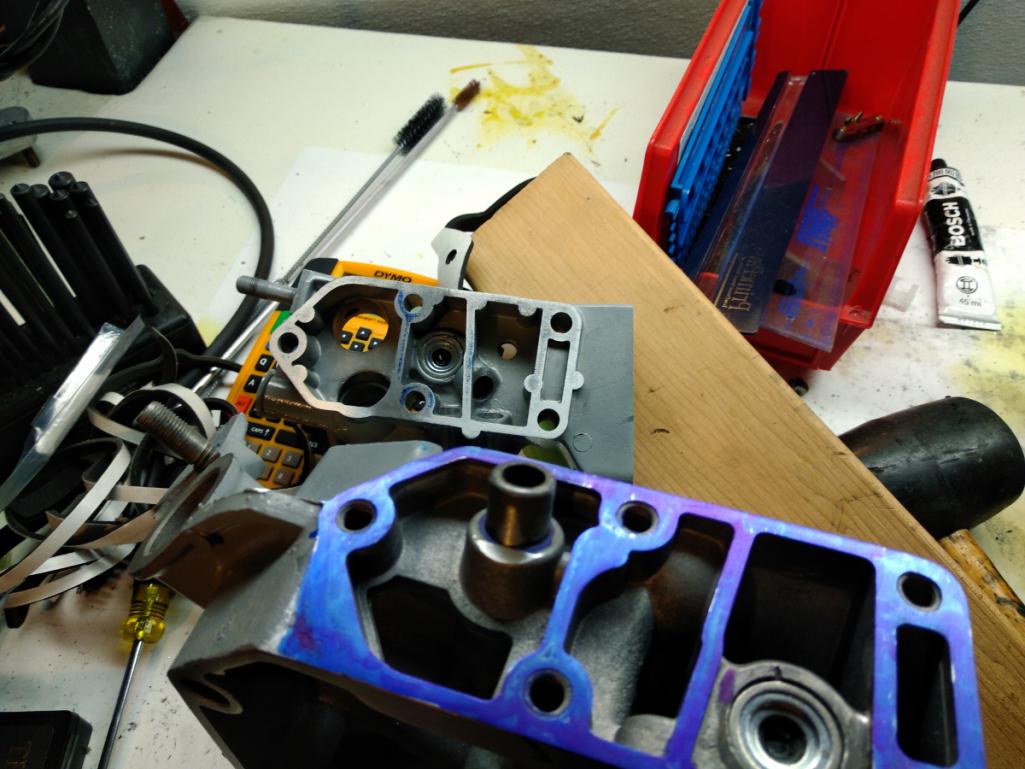
Posted by: r3dplanet Jul 14 2018, 09:12 PM
Next on the list is the installation of the oil bypass valves. There are two of them. They are the same and much better made than the originals. You can see where the old ones were peened into place. But these ones have a much better fit. I just used a socket to drive them into place after cleaning the bores.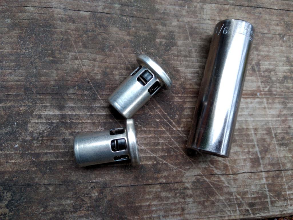
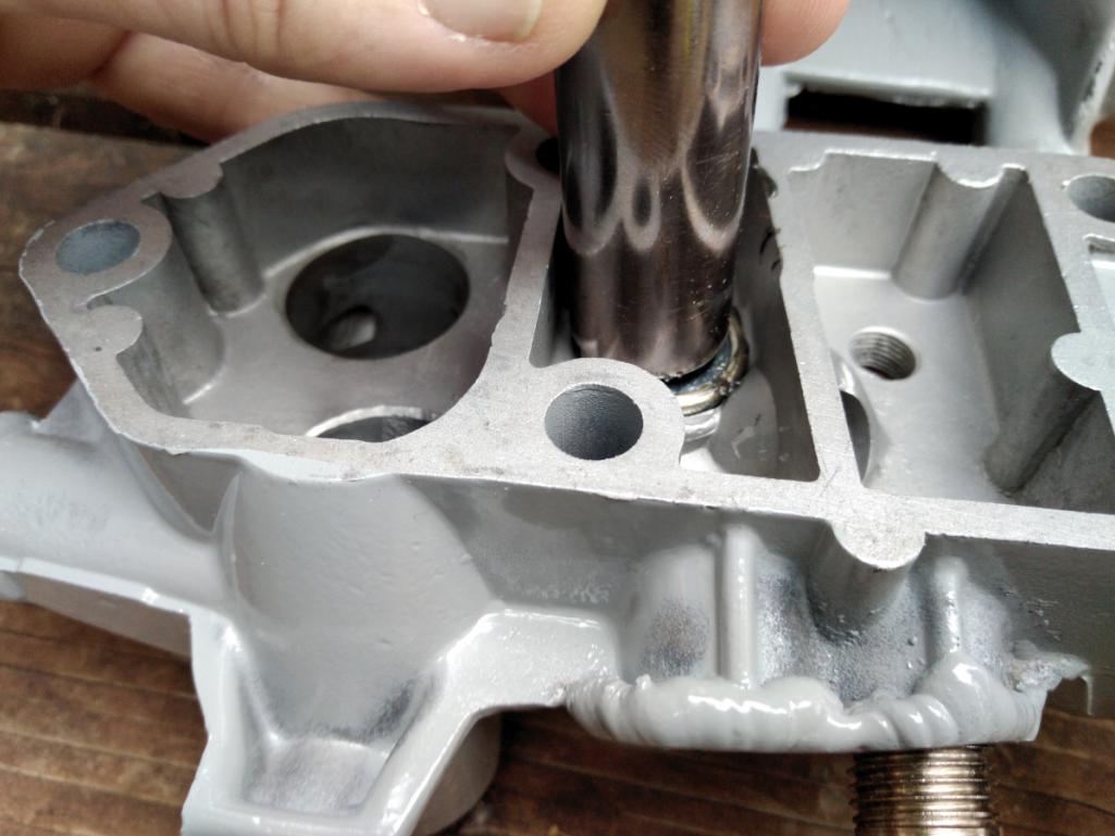
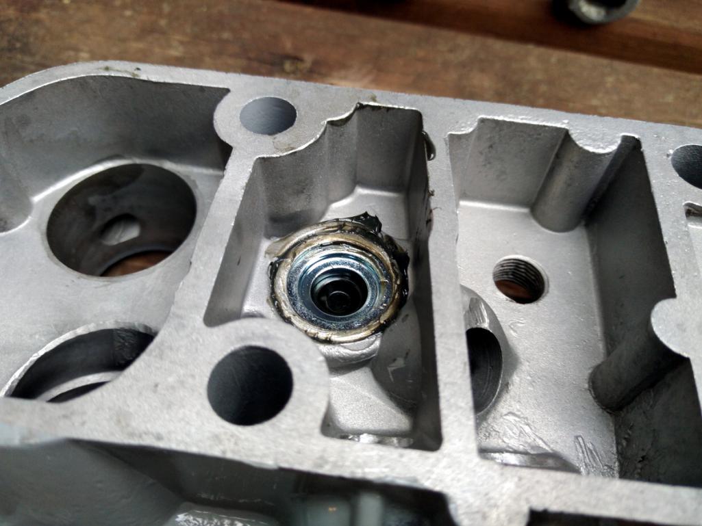
Finally, here are the mating surfaces of the cover nicely matched and polished with the valves installed.
Modern oil filters have bypass valves internal to their construction, so apparently this engine gets three bypass valves. If that proves to be a problem, I can always shove that poor nickel right back into place. But I doubt it will be a problem.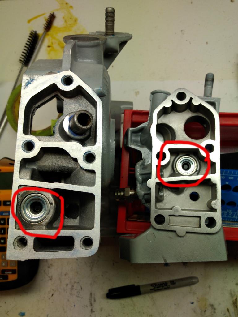
Posted by: r3dplanet Jul 14 2018, 09:17 PM
Next is an easy one. Just the fuel pump block off knob. I somehow ended up with two of them of differing makes, so I chose the round one. Like every other seal on the engine it has a Viton o-ring. Just a tiny bit of oil and it fits into place.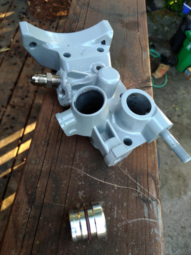
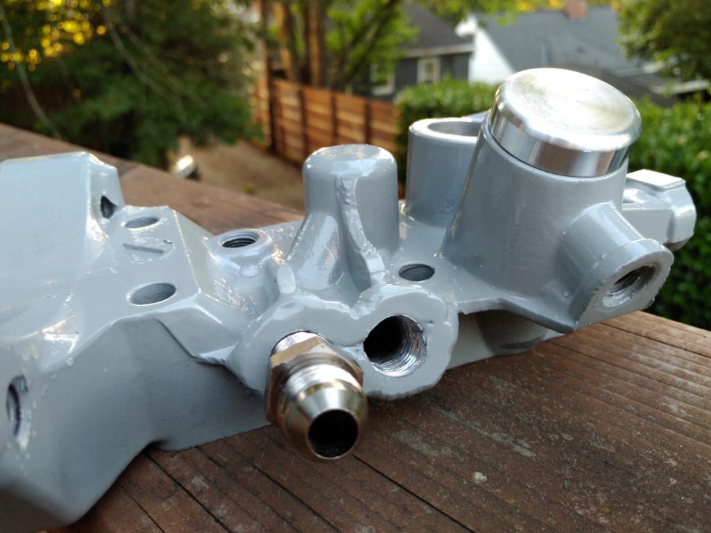
Posted by: r3dplanet Jul 14 2018, 09:25 PM
Then it's time to install the first of two large seals. This one installs into the cover on the pulley end of the crankshaft, the other one will cover the crankshaft gear on the transmission side.
These come in two varieties in terms of the seal material. It's a flat steel ring with either Viton or another type of black material. I'm not sure which is better but I suppose they both have their benefits. I chose the Viton one but if it leaks I can always swap it out. Once installed it pushes right up against the oil slinger on the crank.
Since this is Viton, I'm using Gasgacinch to seal it. If it were the other one, I'd use moly grease like the manual states. Viton is great but I've read it's best used where it doesn't seal a moving part. We shall find out.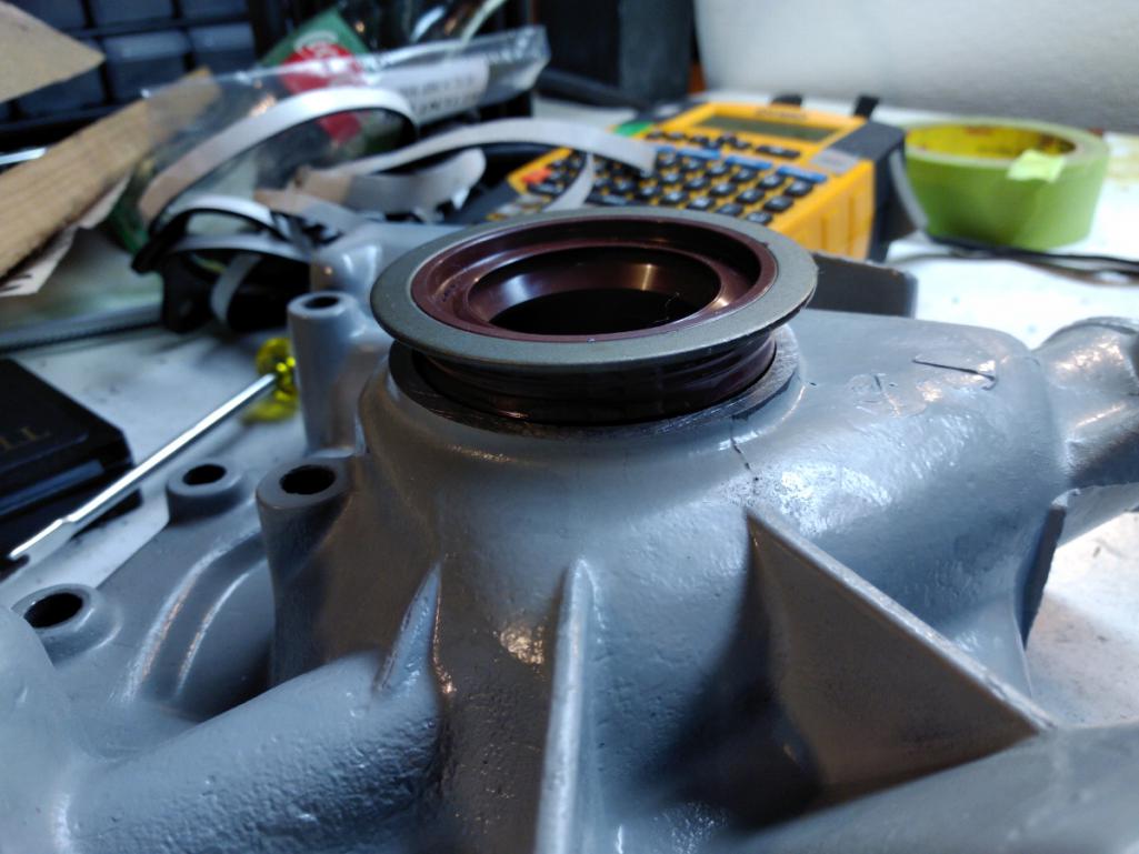
Posted by: r3dplanet Jul 14 2018, 09:44 PM
Then it's finally time to install the cover.
Again I'm coating these gaskets with Permatex High-Tack. In the photo below the first gasket slides over the four bottom studs, but the rest of the cover is held in place by seven bolts. On this subject, nearly all of the bolts on the engine so far are longer than the originals. Most of the time the bolts were threaded in maybe 3/8". Sort of surprising given steel fasteners into aluminum blocks that already have very deep threads. So I'm taking advantage and using longer bolts. The four nuts on the four bottom studs are only temporary. Later, these nuts will be removed and replaced with the front engine mount plate.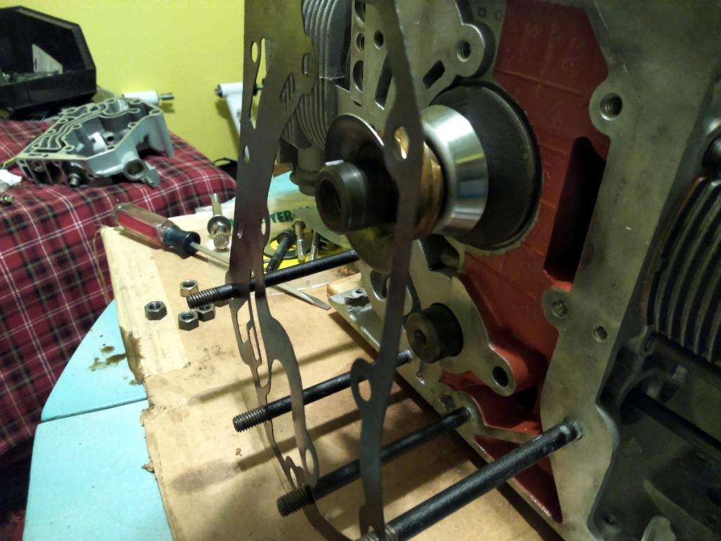
Be very sure to coat the brass distributor gear with grease before proceeding!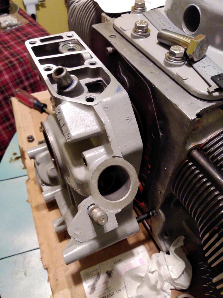
Then pop on the cover and torque down four nuts and seven bolts. Again, I'm using JetLube on the bolts to prevent corrosion and angry fits come disassembly.
Then on goes the top gasket and finally the top part of the cover. No idea why I didn't get a photo but the top cover is held down with another five bolts. This engine is a marvel just for the sheer number of fasteners!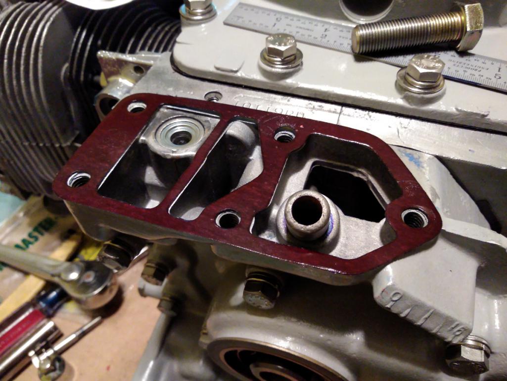
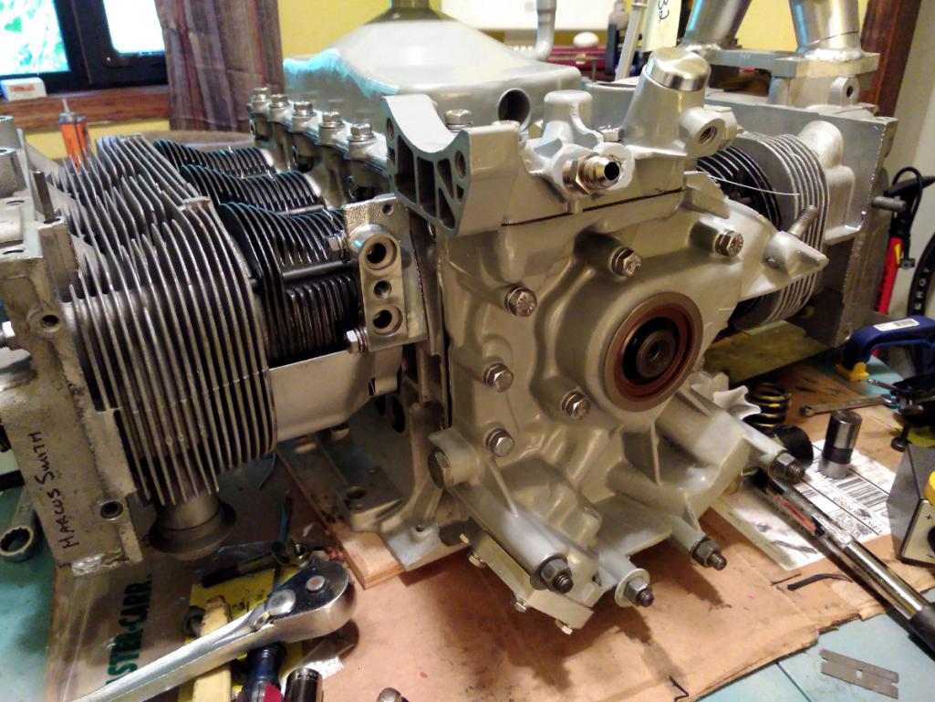
With the Cover of Many Uses now installed, the alternator and belt pulley can be installed. Or they could if I had them. Still tracking them down. Also, the harmonic damper can be installed but I'm waiting to mix up some clear paint for it.
Posted by: r3dplanet Jul 14 2018, 10:01 PM
Okay -
The last bit for today is just some notes on the distributor. Here is a lovely HEI unit mated to a long shaft just for the Corvair. You can buy them from Seth Emerson, one the authors of the Performance Corvairs: How to Hotrod the Corvair Engine and Chassis . The website is www.perfvair.com.
Originally I wanted to use a stock distributor and throw a Pertronix Ignitor II into it. Or even cooler, a Mallory Unilite. But this distributor has plenty of obvious modern features as well as having a smaller overall outside diameter, so hopefully it will fit easier into the engine bay. I priced out rebuilding an original distributor but when all is said and done it's more expensive. This new HEI unit costs $200, so it's more than a fair price in my little opinion.
With either distributor the drive gear needs to be swapped for a reverse drive gear. Clark's sells a kit for this, which includes two thrust washers - one of which has offset keys. If you use the stock distributor you must replace the original thrust washers with these. But on the HEI unit I don't think it's necessary and I know it's not possible. The idea as I understand it is that the thrust of force against the gear and cam is now opposite due to reverse rotation, so the thrust washer needs to be replaced with a mirror image of itself.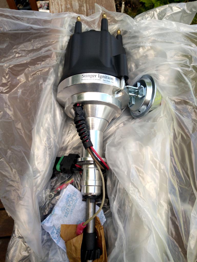
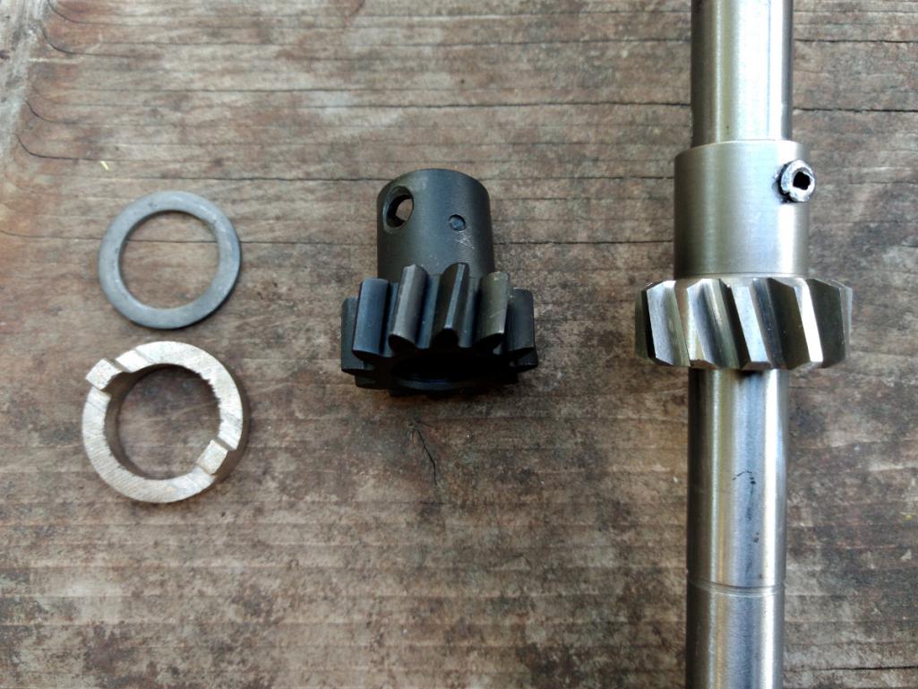
Anyway, here it is as of today in mock-up. 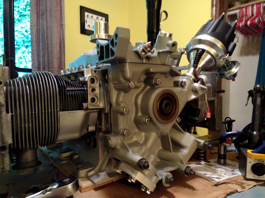
So right now I need to get some missing engine tins, an alternator, a belt pulley, starter, and a few other bits. So it's coming along. But likely nothing further will happen until the oil pan and lifters return. This concludes the broadcasting day.
Posted by: DaveO90s4 Jul 15 2018, 07:39 AM
Hi Marcus. What ring gear will you be using? If 130 tooth then you will probably find that a 911 or 1.4kW VW 9-tooth 25mm diameter pinion will work. The 911 has a 33mm pinion at rest length - which would mean your ring gear would need to be 35mm back from the starter mounting face when fitted to the flywheel I think)
Dave
Posted by: Tbrown4x4 Jul 15 2018, 07:58 AM
I'm pretty sure I read somewhere the Corvair engine was the most expensive engine that GM had built at the time.
Not surprising, considering all the aluminum castings.
Making great progress! Love the updates.
Posted by: mepstein Jul 15 2018, 08:35 AM
Okay -
The last bit for today is just some notes on the distributor. Here is a lovely HEI unit mated to a long shaft just for the Corvair. You can buy them from Seth Emerson, one the authors of the Performance Corvairs: How to Hotrod the Corvair Engine and Chassis . The website is www.perfvair.com.
Originally I wanted to use a stock distributor and throw a Pertronix Ignitor II into it. Or even cooler, a Mallory Unilite. But this distributor has plenty of obvious modern features as well as having a smaller overall outside diameter, so hopefully it will fit easier into the engine bay. I priced out rebuilding an original distributor but when all is said and done it's more expensive. This new HEI unit costs $200, so it's more than a fair price in my little opinion.
With either distributor the drive gear needs to be swapped for a reverse drive gear. Clark's sells a kit for this, which includes two thrust washers - one of which has offset keys. If you use the stock distributor you must replace the original thrust washers with these. But on the HEI unit I don't think it's necessary and I know it's not possible. The idea as I understand it is that the thrust of force against the gear and cam is now opposite due to reverse rotation, so the thrust washer needs to be replaced with a mirror image of itself.
Anyway, here it is as of today in mock-up.
So right now I need to get some missing engine tins, an alternator, a belt pulley, starter, and a few other bits. So it's coming along. But likely nothing further will happen until the oil pan and lifters return. This concludes the broadcasting day.
That engine would look cool just left on display.
Posted by: r3dplanet Jul 15 2018, 01:53 PM
Hello there. Yes, I'm using a 130 tooth ring gear on the flywheel. That's stock for the 914, yes? Thanks for doing this legwork for me. This is such great information - thank you for making all the measurements! Following your advice I'm on the lookout for a 911 starter, or perhaps a modern high torque starter. Maybe something like this?
https://www.amazon.com/STARTER-PORSCHE-1967-1969-003911023A-3911023/dp/B079VVN6TN
I don't like to buy from Amazon, but it's a good photo. I'll likely buy from Pelican or similar.
Hi Marcus. What ring gear will you be using? If 130 tooth then you will probably find that a 911 or 1.4kW VW 9-tooth 25mm diameter pinion will work. The 911 has a 33mm pinion at rest length - which would mean your ring gear would need to be 35mm back from the starter mounting face when fitted to the flywheel I think)
Dave
Posted by: euro911 Jul 15 2018, 02:22 PM
We saw a guy driving one of those MANX SRs last week. Hadn't seen one in decades. I knew they used the VW bug pan and typically the bug drive train, but wondered if he stuck a Porsche motor in it because it sounded like a flat 6 when he pulled up next to us at a stop light.
My wife asked him what motor he was running, he said Corvair ... and we noticed a small Chevrolet bowtie emblem on the rear deck after he passed us ...
Looked similar to this one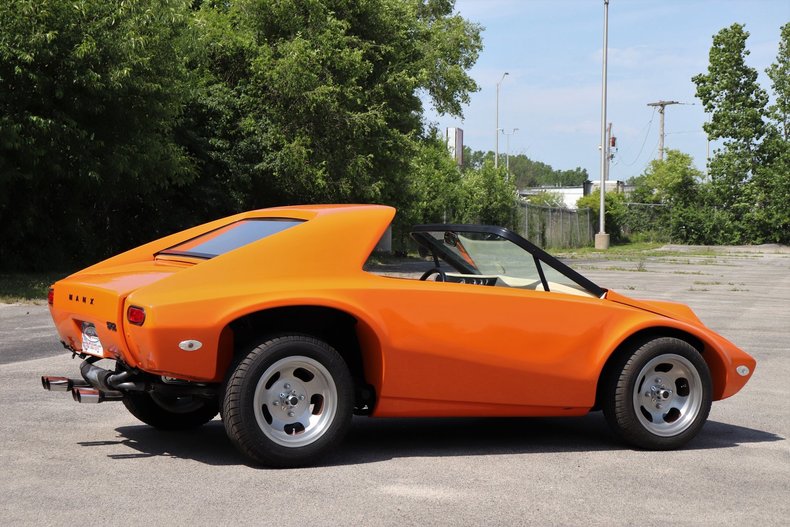
Posted by: r3dplanet Jul 15 2018, 03:32 PM
I'm not surprised. I know way more about Mopar than GM, and I know that costly expense and time were the main problem for engines like the 426 Hemi. Very complicated engines build by specialist hands.
GM was and is an anomaly to me in terms of this engine. They clearly live up to their reputation for not spending any penny they didn't absolutely have to spend. This engine is so cool on so many levels, but there are no shortage of examples on cost cutting. Maybe they cut more costs because the engine was already expensive to build. The aluminum castings certainly come to mind. I keep finding never ending places where I could have cut more aluminum casting flash. Despite all the time I spent with a Dremel, I'll bet there's another cupful of flash I could have removed.
Thank you for the goodwill. It helps keep me going.
I'm pretty sure I read somewhere the Corvair engine was the most expensive engine that GM had built at the time.
Not surprising, considering all the aluminum castings.
Making great progress! Love the updates.
Posted by: r3dplanet Jul 15 2018, 03:34 PM
You might be more right than you know. If this engine doesn't run perfectly it may very well be a display item for a long time.
That engine would look cool just left on display.
Posted by: r3dplanet Jul 15 2018, 03:51 PM
Good find! That thing looks like a weekend vehicle from Logan's Run. That is, if they were allowed to leave the domed city.
Ah, the never-ending malleability of the Beetle. I have three Beetle projects in my driveway. My neighbors *love* me. One of the frames is shot in terms of pans and rust. If I were working with a longer time frame I would love to convert it into a Formula Vee car. When I was in Berlin a couple of years back I saw this example at a VW dealership.
I have a real love/hate relationship with the Beetle conversions like the Manx, Baja, etc. and the mmm... vehicle.. in your photo. I love the Beetle and how it's a great platform for so many other cool vehicles. But in modern times my opinion has changed to preserving them instead of cutting them up.
Having said that, I really would have loved to build up a Formula Vee, either VW or Corvair powered. A trashed frame like mine is the best starting point. It's the same argument for motorcycles. Breaks my heart to see nice originals cut into cafe racers, but it's okay if the bike was already decrepit.
One note about the orange Manx in your photo. The exhaust looks very much like what I want to do. The easy part about a Corvair engine in a 914 is that the exhaust is very easy to access. My plan is to use very simple headers and pipe it right into a 914 exhaust. But not the Monza-style one on the Manx.
I'm wondering about a subtle cue for my GM-powered 914, too. Maybe a hatch emblem or something.
Anybody want a Beetle project?
We saw a guy driving one of those MANX SRs last week. Hadn't seen one in decades. I knew they used the VW bug pan and typically the bug drive train, but wondered if he stuck a Porsche motor in it because it sounded like a flat 6 when he pulled up next to us at a stop light.
My wife asked him what motor he was running, he said Corvair ... and we noticed a small Chevrolet bowtie emblem on the rear deck after he passed us ...
Looked similar to this one
Posted by: r3dplanet Jul 20 2018, 11:11 PM
Here's a mini how-to on alternator modifications. Huge gratitude to DaveO90s4 for sharing his discovery about the pulley - it will make an important difference for the belt alignment.
From 1960-1963 the Corvair used a generator. From 1964-69 it used an alternator. You can buy very expensive bespoke alternators just for the Corvair (I've seen them on eBay for $600) or even go high dollar and rebuild the generator as an alternator. But my project funds are dwindling and I never wanted to be the guy with alternator bragging rights whilst showing off the engine in a parking lot.
So here's the cheap way out.
Amazingly, the alternator to be used is the venerable GM internally regulated alternator that you can buy at any any flaps. Three cheers for continuity (heh)! Mine is a 64 amp alternator picked up locally for $58. All that's necessary is to swap the front cover with a period Corvair cover, swap the bearing assembly, and then most importantly swap the alternator fan with a 1964 only fan/pulley one-piece assembly. I bought mine from Clark's for $22. I put out a want-ad on a Corvair forum but they don't separate classified ads from discussion, so it immediately devolved into a discussion about how magnetos work. Ugh. The pulley isn't in the Clark's catalog. I just called and asked. The front cover was cheap also.
Here's the FLAPS alternator: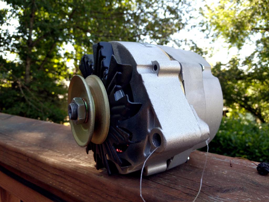
And here is the 1964 only one-piece pulley / fan combo unit: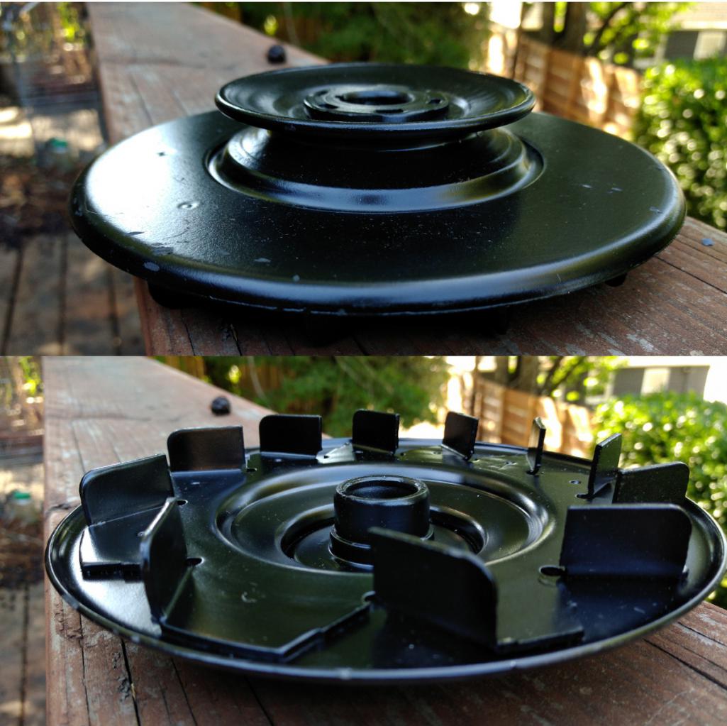
You can see here that the old front cover has it's mounting holes right at the bottom, instead of the more modern cover with its holes 180 degrees apart.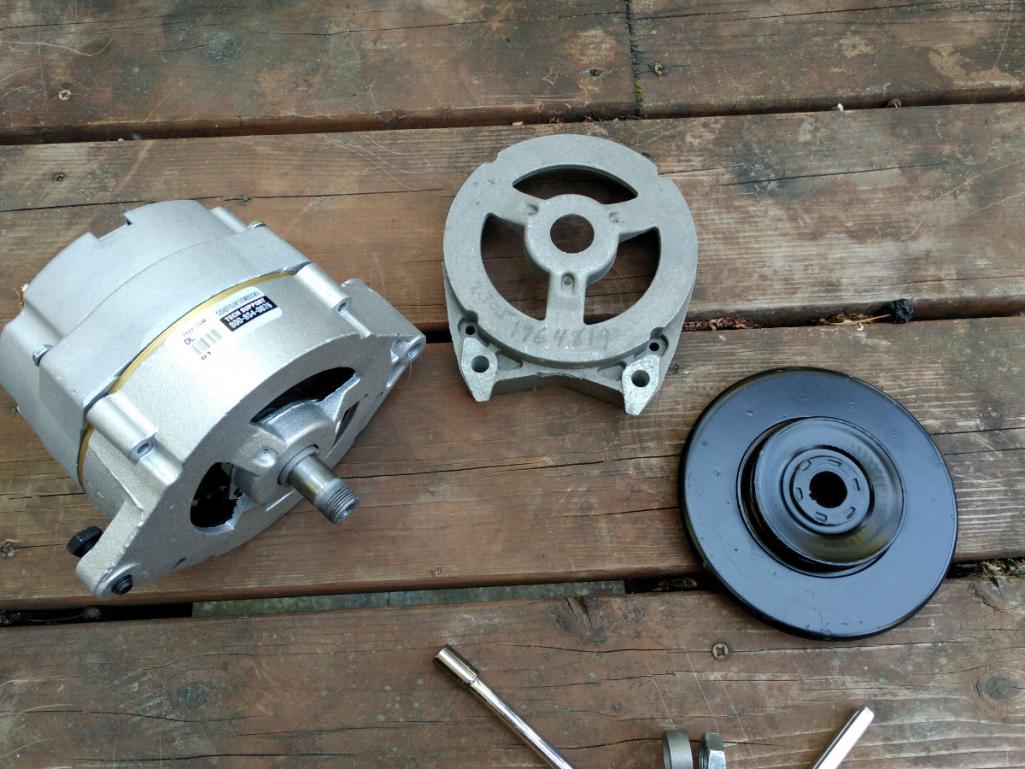
Here is the bearing assembly. It's just three screws, a sealed bearing, and a retainer plate. The bushing is there for looks. But on that subject there is a thick bushing that won't be used. Just use the two smaller ones to get the right clearance.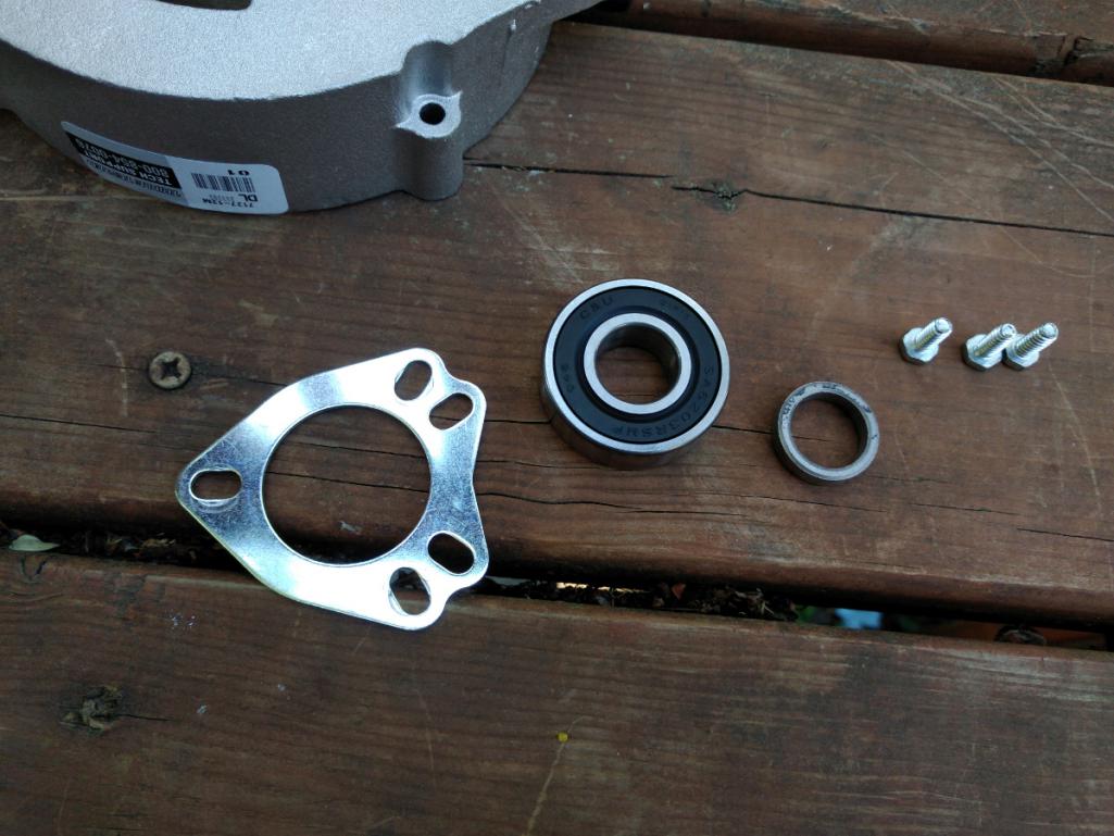
Here is the bearing assembly pressed into the Corvair front cover. Somewhat troubling was that the bearing was easily popped out of the new cover just with my fingers. I used a press to insert the bearing into the Corvair cover.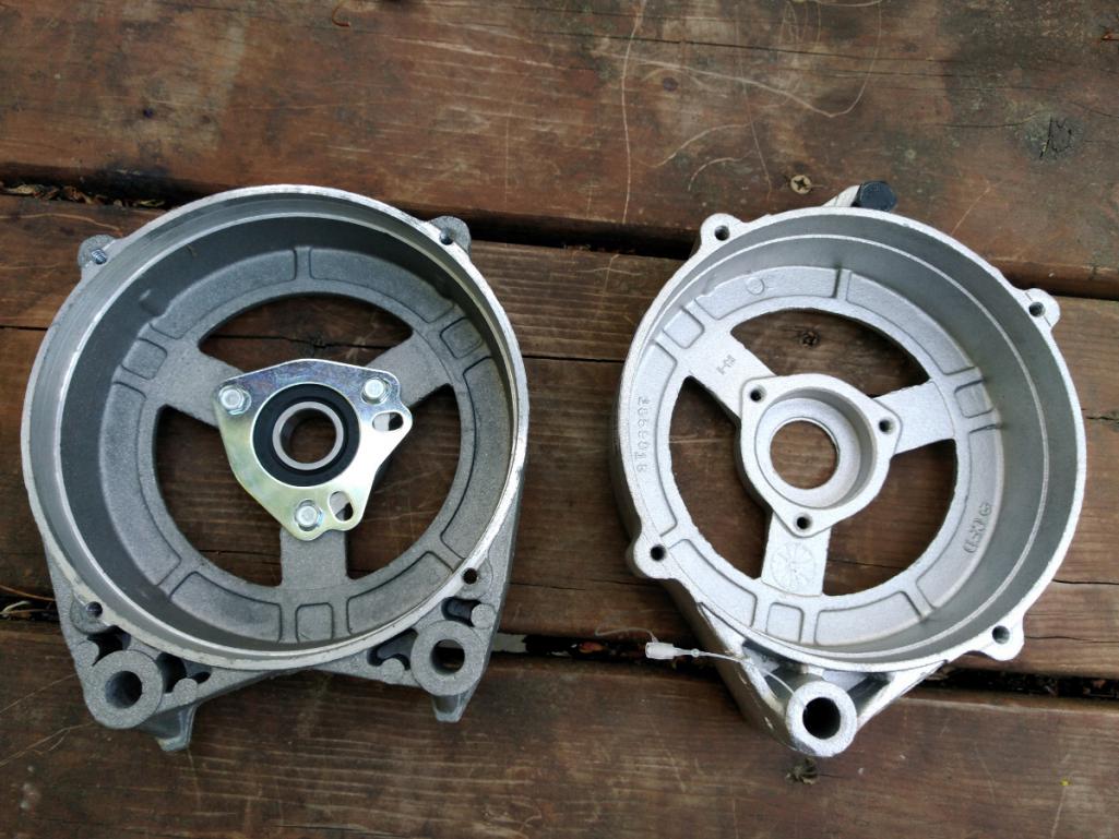
And here it is mostly assembled. Pay no attention the bolt at the bottom. It's inserted the wrong way; it should insert from the other side. All four #10-24 2" bolts match perfectly to the new alternator housing. The fan spins great.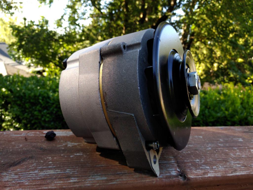
But some info on that fan. Forever and a day the wisdom about reverse rotation engines has been to also utilize a reverse fan on the alternator. Since the alternator doesn't care which way it spins, the fan should blow cooling air in the most efficient way, so while the alternator doesn't care about direction the fan should. Ideally that means the blades should be flipped 180 degrees. On a normal alternator setup without this '64 only pulley/fan assembly a common reverse fan would be installed. But there aren't any reverse '64 only pulleys. Every other pulley after 1964 had a separate fan and pulley, just like the very first photo above.
This is where DaveO90s4 did some brain thinking. He found that using the later standard sized pulley dropped the belt in relation to the idler pulley. The belt should run along the both pulleys on the same plane. But the alternator pulley is of a smaller diameter and it had a tendency to throw the belt on his engine. But with this pulley it has that large guard and a larger diameter pulley to equalize the run.
I would never have known to do this. Maybe someone out there in fabrication land can manufacture a reverse '64 only pulley, but according to racer lore it should work just fine.
I found this helpful table detailing the Corvair generators and pulleys, but the short version is that Part #3848042 is what you need.
https://murfy.us/doku.php?id=timtechcorvairwiki:08_electrical_systems:generatorcodes
Posted by: r3dplanet Jul 20 2018, 11:43 PM
Also, a sad note about the Ford roller rocker tips.
Unless I find some way to modify them they won't fit. It took me a bit to figure out some trouble. But the gist of it is that the roller tip rockers are slightly taller from the round base to the top. So if I cinch down the adjuster nut to where the shorter pushrods are correct, it seizes.
It seizes because the bottom of the rocker makes contact with the face of the mounting stud. It just can't go in any farther because there's no clearance. The stock rockers still leave maybe .030" of clearance. So it appears that at least in my application the roller tips won't work.
If I had the time and money I'd buy the good roller rocker kit from Clark's, but I'm short on both. So stockers it is. It's a bit of a pisser but at least I have a workaround.
Stock rocker: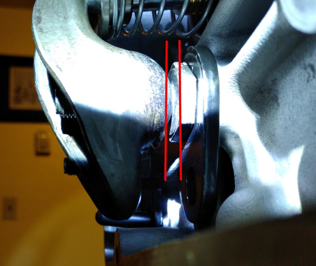
Ford rocker: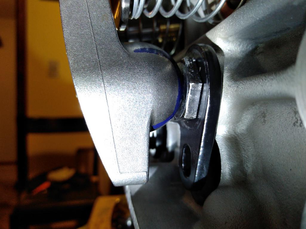
Posted by: DaveO90s4 Jul 21 2018, 01:20 AM
Pleased to be able to pass on any snippets of info I've gleaned along the way.
Had you inclination you could remove the blades from the '64 pulley (leaving the spot welds in place) to yield a flat-ish rear of the shroud, and then sandwich the later model alternator fan into place. I doubt the thickness of the sandwich would affect belt tracking.
Or just leave the '64 pulley as it is. That's what I'm going to do. - so as to give me time to fit the new starter to the 914, fix the electric windows in the 911, replace the water pump in the 944 etc etc....
You did well with that purchase from Clark's. Mine cost more than twice as much, then exchange rates, then shipping. The tyranny of living upside down... But at least mine's fixed and I learnt something I could pass on.
Cheers
DaveO
Posted by: Dr Evil Jul 23 2018, 09:59 AM
Also, a sad note about the Ford roller rocker tips.
Unless I find some way to modify them they won't fit. It took me a bit to figure out some trouble. But the gist of it is that the roller tip rockers are slightly taller from the round base to the top. So if I cinch down the adjuster nut to where the shorter pushrods are correct, it seizes.
It seizes because the bottom of the rocker makes contact with the face of the mounting stud. It just can't go in any farther because there's no clearance. The stock rockers still leave maybe .030" of clearance. So it appears that at least in my application the roller tips won't work.
If I had the time and money I'd buy the good roller rocker kit from Clark's, but I'm short on both. So stockers it is. It's a bit of a pisser but at least I have a workaround.
Stock rocker:
Ford rocker:
I had to do the same damn thing. Ended up with stockers. The rollers came with their own special studs, did yours?
Man, this build is so right. Mine looks like a tossed it all together comparatively. Things that you did that I would definitely do once I get into this thing again in the future is all the work on the oil pump and the cover of many uses. What a raging bitch those things were to do. Still leak. I was under pressure to get the bus moving under its own power and out of where I was moving from. Now, Im just too bogged down to really mess with it. This will be a classic thread.
Posted by: Dr Evil Jul 23 2018, 10:00 AM
Here's a mini how-to on alternator modifications. Huge gratitude to DaveO90s4 for sharing his discovery about the pulley - it will make an important difference for the belt alignment.
From 1960-1963 the Corvair used a generator. From 1964-69 it used an alternator. You can buy very expensive bespoke alternators just for the Corvair (I've seen them on eBay for $600) or even go high dollar and rebuild the generator as an alternator. But my project funds are dwindling and I never wanted to be the guy with alternator bragging rights whilst showing off the engine in a parking lot.
So here's the cheap way out.
Amazingly, the alternator to be used is the venerable GM internally regulated alternator that you can buy at any any flaps. Three cheers for continuity (heh)! Mine is a 64 amp alternator picked up locally for $58. All that's necessary is to swap the front cover with a period Corvair cover, swap the bearing assembly, and then most importantly swap the alternator fan with a 1964 only fan/pulley one-piece assembly. I bought mine from Clark's for $22. I put out a want-ad on a Corvair forum but they don't separate classified ads from discussion, so it immediately devolved into a discussion about how magnetos work. Ugh. The pulley isn't in the Clark's catalog. I just called and asked. The front cover was cheap also.
Here's the FLAPS alternator:
And here is the 1964 only one-piece pulley / fan combo unit:
You can see here that the old front cover has it's mounting holes right at the bottom, instead of the more modern cover with its holes 180 degrees apart.
Here is the bearing assembly. It's just three screws, a sealed bearing, and a retainer plate. The bushing is there for looks. But on that subject there is a thick bushing that won't be used. Just use the two smaller ones to get the right clearance.
Here is the bearing assembly pressed into the Corvair front cover. Somewhat troubling was that the bearing was easily popped out of the new cover just with my fingers. I used a press to insert the bearing into the Corvair cover.
And here it is mostly assembled. Pay no attention the bolt at the bottom. It's inserted the wrong way; it should insert from the other side. All four #10-24 2" bolts match perfectly to the new alternator housing. The fan spins great.
But some info on that fan. Forever and a day the wisdom about reverse rotation engines has been to also utilize a reverse fan on the alternator. Since the alternator doesn't care which way it spins, the fan should blow cooling air in the most efficient way, so while the alternator doesn't care about direction the fan should. Ideally that means the blades should be flipped 180 degrees. On a normal alternator setup without this '64 only pulley/fan assembly a common reverse fan would be installed. But there aren't any reverse '64 only pulleys. Every other pulley after 1964 had a separate fan and pulley, just like the very first photo above.
This is where DaveO90s4 did some brain thinking. He found that using the later standard sized pulley dropped the belt in relation to the idler pulley. The belt should run along the both pulleys on the same plane. But the alternator pulley is of a smaller diameter and it had a tendency to throw the belt on his engine. But with this pulley it has that large guard and a larger diameter pulley to equalize the run.
I would never have known to do this. Maybe someone out there in fabrication land can manufacture a reverse '64 only pulley, but according to racer lore it should work just fine.
I found this helpful table detailing the Corvair generators and pulleys, but the short version is that Part #3848042 is what you need.
https://murfy.us/doku.php?id=timtechcorvairwiki:08_electrical_systems:generatorcodes
Yup, did this as well. Waaaaay cheaper and available parts. Only special piece is the cover. I kept mine normal corvair rotation since I mated it to a two speed PG.
Posted by: r3dplanet Jul 23 2018, 10:35 AM
Right? I spent $90 including the alternator. Otherwise you get to spend $300. It never really hit me that you were using the Powerglide. Intersting..
Current status:
* I'm *stilll* waiting on the machinist to finish the oil pan. Can't installl the pushrods, tubes, lifters, rockers, etc untill it returns.
* Sorting out starter ideas.
* Working on small stuff, like painting the harmonic balancer.
* The builder I hired three months ago to rebuild the Type-4 engine hasn't even started yet. Sigh.
Yup, did this as well. Waaaaay cheaper and available parts. Only special piece is the cover. I kept mine normal corvair rotation since I mated it to a two speed PG.
Posted by: DaveO90s4 Jul 23 2018, 05:19 PM
....starter ideas...
I received and installed my new starter yesterday. It is 1.4 kw (OEM 914 is 0.8kW). This is a high torque model that allows the user to rotate and set the housing in multiples of 20 deg to get best body / solenoid clearance. And was manufactured to set the pinion length to precisely match my unique ring gear depth.
That was $500 - but not bad for a brand new more powerful starter that fits perfectly.
My hot start woes are now solved.
Built by CA Performance in Melbourne, Aus.
I'll email you a photo Marcus.
Cheers
DaveO
Posted by: DaveO90s4 Jul 23 2018, 05:21 PM
....starter ideas...
I received and installed my new starter yesterday. It is 1.4 kw (OEM 914 is 0.8kW). This is a high torque model that allows the user to rotate and set the housing in multiples of 20 deg to get best body / solenoid clearance. And was manufactured to set the pinion length to precisely match my unique ring gear depth.
That was $500 - but not bad for a brand new more powerful starter that fits perfectly.
My hot start woes are now solved.
Built by CA Performance in Melbourne, Aus.
I'll email you a photo Marcus.
Cheers
DaveO
Posted by: r3dplanet Jul 23 2018, 06:13 PM
Hopefully that's $500 AUS?
....starter ideas...
I received and installed my new starter yesterday. It is 1.4 kw (OEM 914 is 0.8kW). This is a high torque model that allows the user to rotate and set the housing in multiples of 20 deg to get best body / solenoid clearance. And was manufactured to set the pinion length to precisely match my unique ring gear depth.
That was $500 - but not bad for a brand new more powerful starter that fits perfectly.
My hot start woes are now solved.
Built by CA Performance in Melbourne, Aus.
I'll email you a photo Marcus.
Cheers
DaveO
Posted by: r3dplanet Aug 17 2018, 09:21 PM
Hello. Apologies for the late update.
There are only a few updates to report since I'm still waiting around for my oil pan to return. Despite assurances from a local machinist that surfacing the oil pan would be no big deal, I returned many weeks later and he hadn't even moved the parts off of his office floor. Typical.
So I sent it off to Tom Stark instead and it should return soon.
In the meantime I have the following resolved:
1. Pushrods have arrived
2. Idler pulley is finished
3. Crank pulley is finished
There's nothing left to do until the oil pan arrives. That and rustle up some strong labor to get the engine out of my spare room. The Engine Room.
My engine didn't have an idler pulley along with most of the other ancillaries. I found one on eBay for cheap and finally got to cleaning it. The bearing is no longer made, but there is one that's very close. The shaft of the new bearing has a smaller OD that the original, which is a bit of a bummer. But I used a bit of Loctite 608 bearing retainer and pressed it on. It will work fine.
Here's a photo of the original with a visible part number. 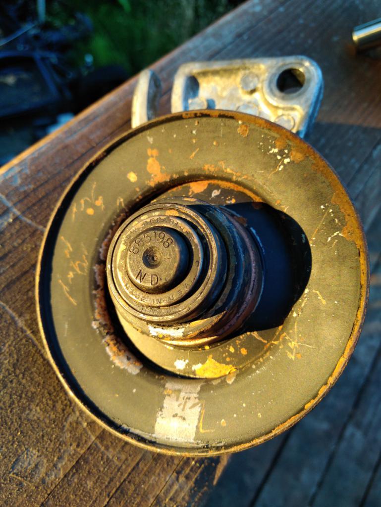
And a comparison of the old and new pulley pulley.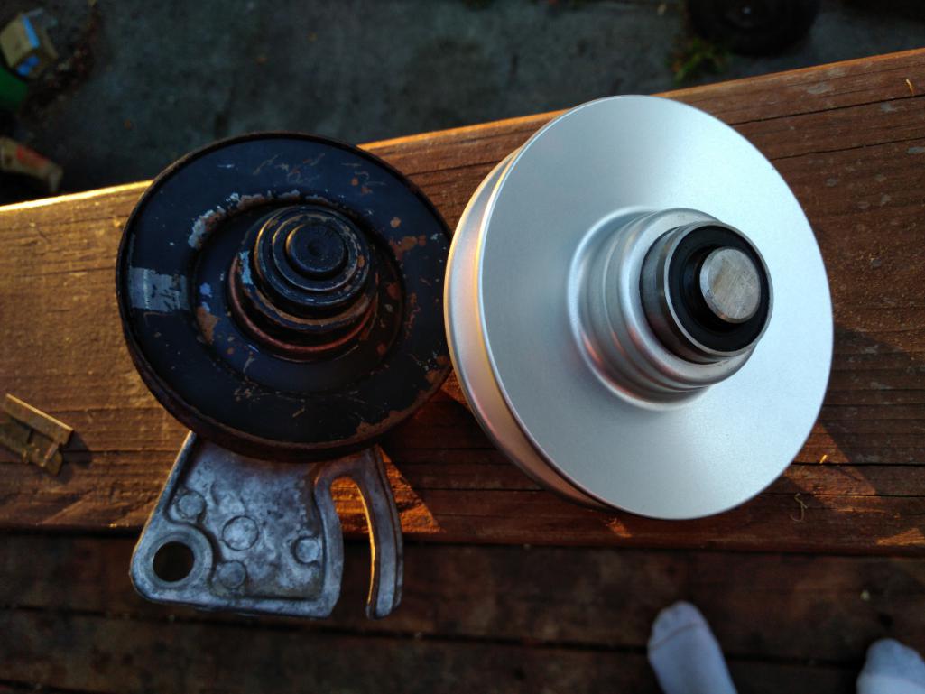
And then a reference measurement for the distance between the pulley and retaining bracket. This is a bit sloppy because there are no parallel surfaces, but hopefully it's good enough; from pulley edge to bracket is .401-ish."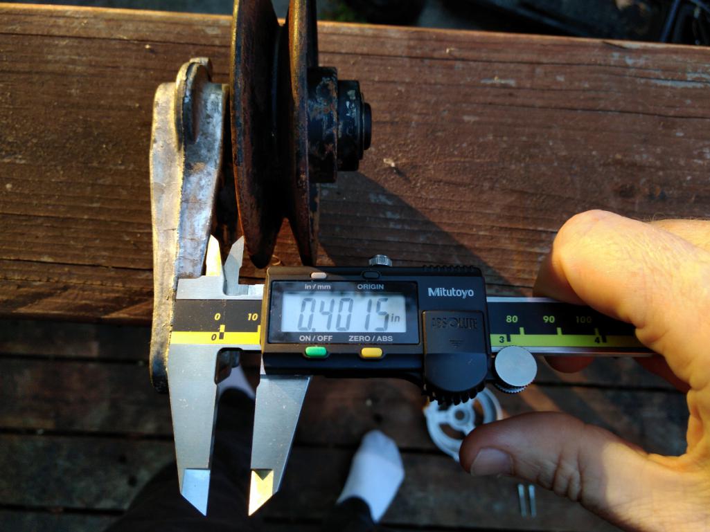
The bracket was another one of these little items where I spent way too much time playing about. The bracket is cast aluminum, so my first thought was to polish it and clear-coat it. But the Dremel polishing didn't work out at all, so instead I pulled out some needle files and removed all the ugly casting leftovers. Smooth surfaces are better. Then I thought about electrocleaning it, so I used a pair of stainless electrodes and some heated 85% phosphoric acid and ran some current through it. Didn't work. That's worked in the past on pot metal but this particular material wasn't having any of my scheme hatchery.
So I gave up and powder coated it chrome, just like the sad oil cooler adapter. But this one came out better. It's a bit ghetto. I would have preferred polish and clear coat.
Here it is assembled: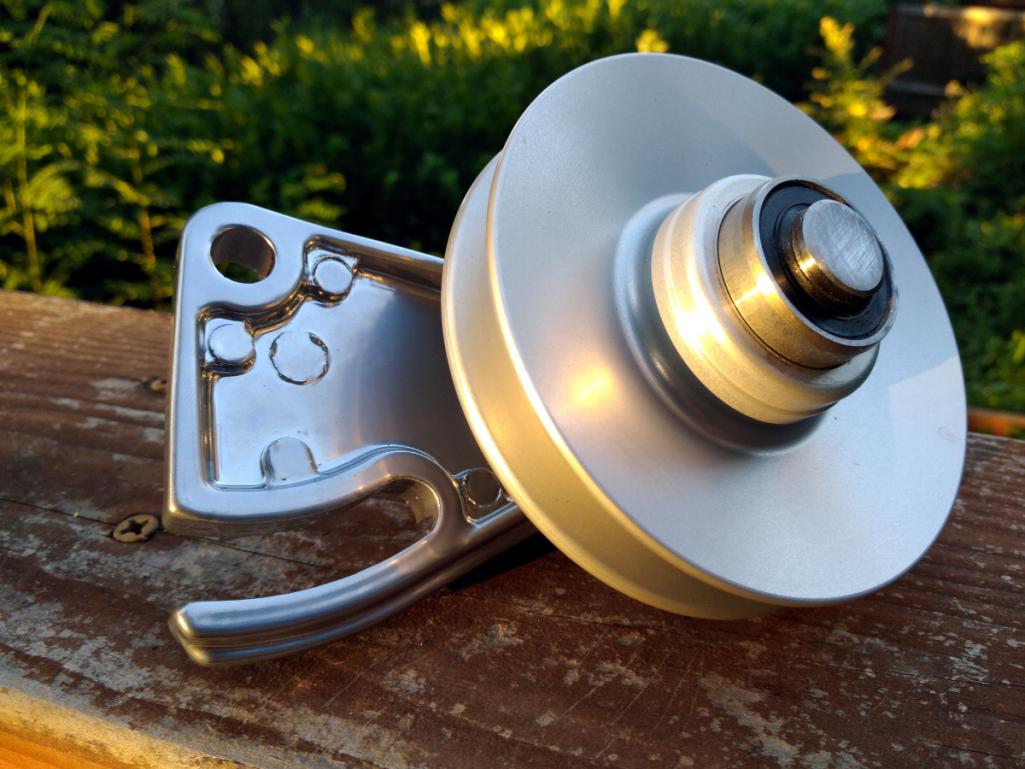
As you can see I'm off by a couple thousandths but in my defense a big hydraulic press isn't a precision instrument. Nor are my clumsy hands. I should have made a temporary gauge block.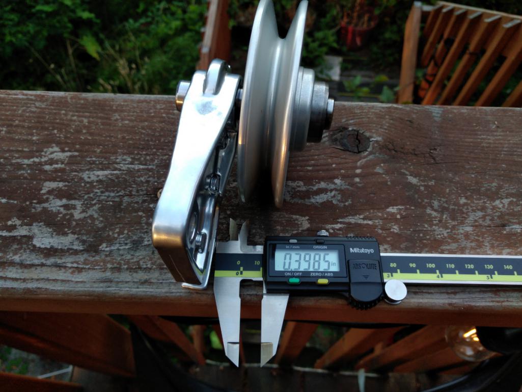
As ever, my cat Mouse keeps me company. She always wants to be where the action is, even if that means dozing from her shop perch. She's just my speed.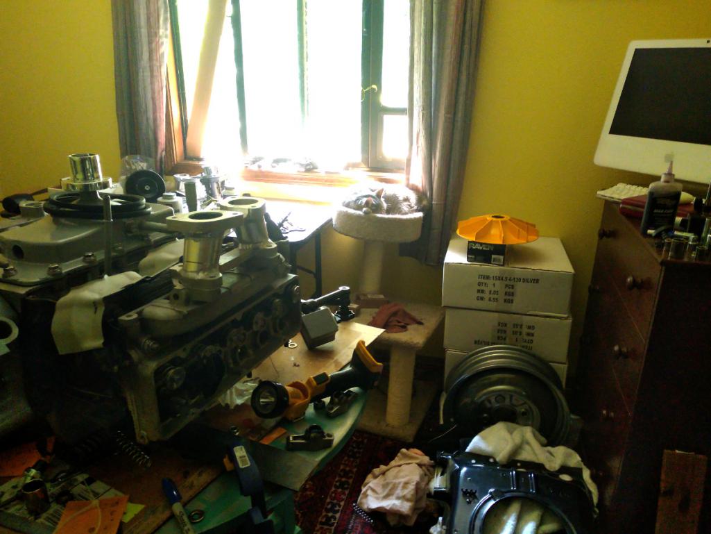
Posted by: r3dplanet Aug 17 2018, 09:24 PM
Another bit of trivia is the finishing of the harmonic damper. I bought it years ago and it was starting to rust a little, so I cleaned and polished it. Feeling crafty, I carefully painted a stylish orange stripe along the timing mark. Afterward I gave it three coats of 2K clear to seal it up. Not very interesting, but it is very nice looking.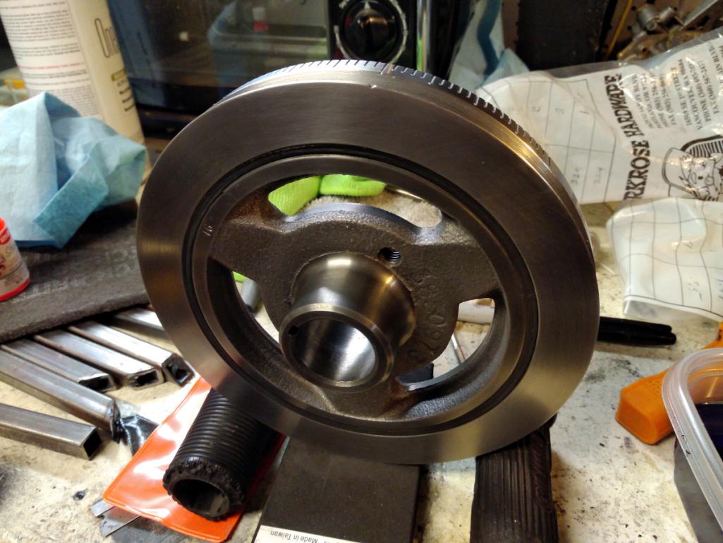
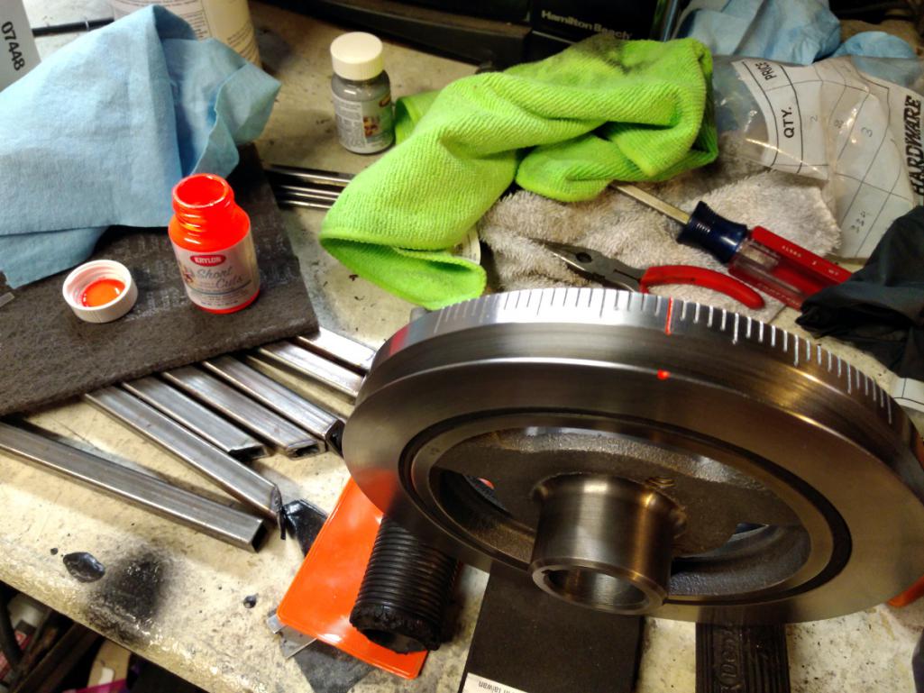
Posted by: r3dplanet Aug 17 2018, 09:31 PM
One final note for now.
I bought my pushrods (or "push rods") from Smith Brothers here in Oregon, in Redmond.
Those guys knew exactly what I needed. They said they do many Corvair pushrods. They can make rods any size to within .005" lengths. All they needed to know was what length of pushrod and what the valve spring ratings are. They arrived two days later.
One of the nonstop troubles I've had with this project is unreliable shop service, excluding those I've singled out along the way who do great work. But locally I've had a miserable time getting anything accomplished. So I was super pleased when these guys pulled right through for me.
I'll get a photo of the rods tomorrow. The Golden Hour is over for today.
Posted by: r3dplanet Aug 18 2018, 02:57 PM
Just a quick note about the pushrods from Smith Brothers.
The measurements are 5/16" outer diameter with 0.083" wall thickness. I don't know what the wall thickness of the factory pushrods are but I might slice one open to find out. The stock pushrods are also 5/16" OD. The rods are made of 4130 chromoly steel with heat treated ends. The spray holes are the same as factory with two on the valve end to act like a lawn sprinkler. The valve ends are rounded just like stock, but the lifter end is spherical unlike stock.
Here's the build card: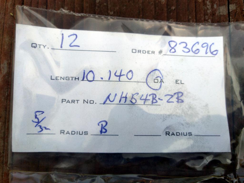
Lifter and valve ends: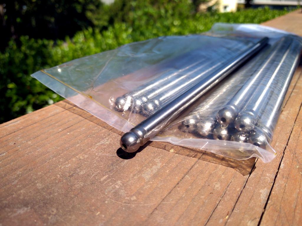
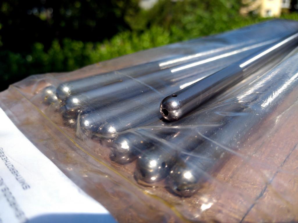
.. and contact info:
I'm hoping to get some strong men in tomorrow or the day after to move the engine outside. Getting anxious to start it!
Posted by: Dr Evil Aug 20 2018, 08:45 AM
I was hanging with my new neighbor/friend last week when his Dad was visiting from Michigan. It so happened that he used to work on the corvair engine line, so of course I brought him next door and opened my bus engine lid for him. Cool guy and a fan of the engine. Small world.
Posted by: r3dplanet Sep 4 2018, 06:03 PM
Hey peeps. I'm *still* waiting for the oil pan work to happen. It's the very last part before I can try to start it up. It's like waiting for Godot.
But since I'm otherwise trying to sell my 914 before the winter arrives, maybe someone out there might be interested in taking over this project and popping into their own car. Just throwing the idea out there. Let me know.
I'll bug the machinist with the oil pan one more time but I absolutely *hate* being that kind of guy. Plus he's doing me a huge favor. Just really want to hear it crank up. Or explode. Whichever way it goes it will be cathartic, and I'm all about catharsis these days.
-marcus
Posted by: Dr Evil Sep 4 2018, 08:39 PM
Man, I just decided to go SVX power in the bus or I’d be all over this. Can’t beat a well documented and assembled corvair motor.
Posted by: r3dplanet Sep 4 2018, 09:13 PM
Just get another bus! Your wife will totally approve. Or if you REALLY want to surprise her then my '65 Barracuda is also up for sale.
Man, I just decided to go SVX power in the bus or I’d be all over this. Can’t beat a well documented and assembled corvair motor.
Posted by: chrisg Sep 9 2018, 10:36 AM
As a slight aside, how important is it to do engine to body tin? I realize the water cooled conversions don’t use it but how does it affect an air cooled application? I would also think that it would make for a very dirty situation considering the upward flow of air. I ran across a site for a shop in CO that has Corvair/Porsche conversion experience but they mention on their site that they lost all of their 914 templates during a move.
DaveO, perhaps you have some input.
Posted by: Dr Evil Sep 9 2018, 11:10 AM
As a slight aside, how important is it to do engine to body tin? I realize the water cooled conversions don’t use it but how does it affect an air cooled application? I would also think that it would make for a very dirty situation considering the upward flow of air. I ran across a site for a shop in CO that has Corvair/Porsche conversion experience but they mention on their site that they lost all of their 914 templates during a move.
DaveO, perhaps you have some input.
I found it easy on the bus. I made rigid cardboard templates and simply used them to fab up metal ones. Worked so well I never prittied them up and used the mock ups as is.
Posted by: r3dplanet Sep 9 2018, 12:19 PM
Yup. DaveO is way ahead on this.
As a slight aside, how important is it to do engine to body tin? I realize the water cooled conversions don’t use it but how does it affect an air cooled application? I would also think that it would make for a very dirty situation considering the upward flow of air. I ran across a site for a shop in CO that has Corvair/Porsche conversion experience but they mention on their site that they lost all of their 914 templates during a move.
DaveO, perhaps you have some input.
Posted by: DaveO90s4 Sep 23 2018, 02:05 AM
Hi all, sorry I'd not seen these latest posts about engine tin until a friend told me over coffee yesterday.
I found making the tin ware a real fun challenge and not hard to do at all - requires a lot of thinking and rather less doing.
I'd be more than happy to explain how I did it for anyone who is fitting a Corvair engine to a 914. Probably best to wake me up by email first. DoveringtonATozemailDOTcomDOTau.
Cheers all
DaveO
Posted by: r3dplanet Sep 23 2018, 12:38 PM
Very cool.
Thinking into the future I think it would be of great benefit to have some plans drawn up and then made available.
If we can get something on paper and into .pdf format I can always host the file so we can link to it from here. Or maybe even a cad file.
Just projecting. Ha. Puns.
Hi all, sorry I'd not seen these latest posts about engine tin until a friend told me over coffee yesterday.
I found making the tin ware a real fun challenge and not hard to do at all - requires a lot of thinking and rather less doing.
I'd be more than happy to explain how I did it for anyone who is fitting a Corvair engine to a 914. Probably best to wake me up by email first. DoveringtonATozemailDOTcomDOTau.
Cheers all
DaveO
Posted by: DaveO90s4 Sep 23 2018, 03:55 PM
Engine tin templates would be great - but not a trivial task. One would have to make all the tinware and fit it and engine, then removeve engine, remove tinware and hammer it flat to make the 'flat' templates.
I have kept most of the paper templates I made, but at best they are close approximations with lots of snipping and fettling required to make the bits fit.
At the crank belt pulley end the tinware will also depend on how the engine has been mounted (I do have as built plans for how I did that and can share if required. As before send me an email to get my attention
Cheers
DaveO
Posted by: chrisg Sep 23 2018, 08:35 PM
Engine tin templates would be great - but not a trivial task. One would have to make all the tinware and fit it and engine, then removeve engine, remove tinware and hammer it flat to make the 'flat' templates.
I have kept most of the paper templates I made, but at best they are close approximations with lots of snipping and fettling required to make the bits fit.
At the crank belt pulley end the tinware will also depend on how the engine has been mounted (I do have as built plans for how I did that and can share if required. As before send me an email to get my attention
Cheers
DaveO
Thanks Dave, I did have the later thought that it would in the end be install and car specific when not working with any set engine mount/location parameters.
Posted by: chrisg Sep 23 2018, 08:45 PM
Hey Marcus, since we are on a bit of an intermission waiting for the oil pan, I was wondering what are your thoughts on how the dual 44 Webers are going to work. Is it a progressive linkage like the stock 4 carb (do I have that correct in how the stock carbs work?)? I re-read this thread and don't remember that being discussed other than seeing the gorgeous intakes you had fabbed.
Posted by: r3dplanet Sep 24 2018, 11:56 AM
Ugggghhhhhh wwabababb ththhhh this intermission suuuuuucks. So sure, let's talk about carbs.
First, just a quick point of order that I didn't fab those intakes. My welding is functional but nowhere near as nice as that work. Those were put together and sold commercially by Tom Knoblauch of American Flat 6. Check out his site here: http://americanflat6.com He's done quite a lot of the machine work for my engine. Definitely a great resource.
The Corvairs came with a number of carburetor options: one single bore carb on either side for the 90, 110, and turbo engines, four carbs for the 140hp, aftermarket high-mounted single carbs, or the very cool modified custom intakes with triple bore Webers. Just like DaveO90s4 has on his. (drool).
I should also mention that there's a very cool and affordable EFI kits that uses stock Ford 6-cylinder EFI bits and EDIS along with many custom made parts. You can get two or four throttle bodies or a kit made just for us big-bore adventurers:
http://www.corvair-efi.com/gen-2-throttle-body-efi-systems/2-9l-and-3-1l-efi-kits-special-order-not-available-thru-clarks/
I might have gone with the Weber triples but they're just so very expensive. So I split the difference and chose double bore Webers or Dellortos - I have both. I know the Webers inside and out so will use those just for ease of tuning and because I know they'll run great.
Once the carbs are mounted on those sweet intakes they sit fairly high and clear of the fan. So all that's needed is a stock throttle cross bar to actuate them. My plan was to do either exactly that, or make a mount and use McMark's bellcrank linkage. I have this linkage for my Type-4 and I absolutely love it. Here's a thread from the group buy:
http://www.914world.com/bbs2/index.php?showtopic=193774&hl=original+customs
Here's what the stock linkage would look like (photos from Americanflat6.com, at http://americanflat6.com/products/2bbl40idfweberkits.html)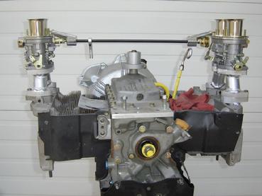
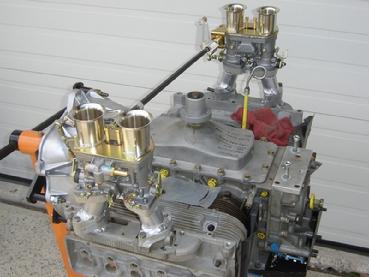
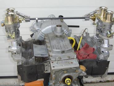
So.. options! Lots of cool stuff. Perhaps the only tiny side note is that I'm often asked about the turbo engine instead. My initial fear was that with the 901 gearbox the engine wouldn't rev far enough for long enough to spool up the turbo. It turns out that's the right answer. Others have poked around with the idea and it doesn't work. So for we 914 people the turbo isn't really viable.
... still waiting for this intermission to end ...
Hey Marcus, since we are on a bit of an intermission waiting for the oil pan, I was wondering what are your thoughts on how the dual 44 Webers are going to work. Is it a progressive linkage like the stock 4 carb (do I have that correct in how the stock carbs work?)? I re-read this thread and don't remember that being discussed other than seeing the gorgeous intakes you had fabbed.
Posted by: andys Sep 24 2018, 01:02 PM
At El Mirage, we ran the 4bbl Holley, 140 heads, with some success. Got to within 4 MPH of the record. If you were to run it on the street, then oil heating the intake would be necessary. That was about 1970.
Andys
Posted by: r3dplanet Sep 24 2018, 01:29 PM
Very cool! I always like the idea of a single four barrel carb. But as you say intake temps are a real problem - the same reason why it doesn't work with a Type-4 or Type-1 engine. Beetles had the heat risers to solve that problem.
Plus it just looks cool.
At El Mirage, we ran the 4bbl Holley, 140 heads, with some success. Got to within 4 MPH of the record. If you were to run it on the street, then oil heating the intake would be necessary. That was about 1970.
Andys
Posted by: DaveO90s4 Sep 24 2018, 03:01 PM
Must be some way to add a heat riser a la early vw?
Speaking if carbs: for a Corvair /. 914 installation I think it highly desirable that the carbs do not extend outboard beyond the rocker covets. The rocker covers clear the chassis when installing the engine by about 1/4 to 1/2 an inch each side. If the carbs extend beyond that then the engine can't be installed or removed with carbs on. It is very difficult to install my carbs with the engine in. And the 12 nuts in total are hard to get at with the engine in. One nut took me two hrs to get on.
Just a thought...
Daveo90s4
Posted by: andys Sep 25 2018, 08:18 AM
Very cool! I always like the idea of a single four barrel carb. But as you say intake temps are a real problem - the same reason why it doesn't work with a Type-4 or Type-1 engine. Beetles had the heat risers to solve that problem.
Plus it just looks cool.
At El Mirage, we ran the 4bbl Holley, 140 heads, with some success. Got to within 4 MPH of the record. If you were to run it on the street, then oil heating the intake would be necessary. That was about 1970.
Andys
After second thought, a type 1 heat riser would be a very simple solution; not at all hard to implement. The advantage is simplified tuning of a single carb. FWIW.
Andys
Posted by: r3dplanet Oct 29 2018, 04:08 PM
Hey gang.
I don't think the oil pan is coming back any time soon. So I finally broke down and bought a third oil pan. This time it's the Clark's brand. Like the Otto it's also made from cast alumin(i)um. Thankfully this is one is dead nuts flat so it doesn't need any modifications. So I suggest that if you ever build your own Corvair engine just cough up the $300 for the Clark's plan. Maybe one day my other Otto oil pan will return. If it does I'll pass it on to another adventurer.
The boasting points for the Clark's pan are:
* tall internal baffles to reduce slop and increase thermal absorption (that's a fun word)
* actual flat mating surface
* two rear-facing pipe threaded holes -> one for the drain bolt to get really good drainage, and another for an oil temp sensor. That's a nice touch.
The main caveat is that the finish isn't nearly as good as the Otto, but I don't care any more. The cost smarts though.
In the next few days I'll have a friend come over and help me flip the engine so I can install the pan. Once installed, it's a straight path to completion. Finally.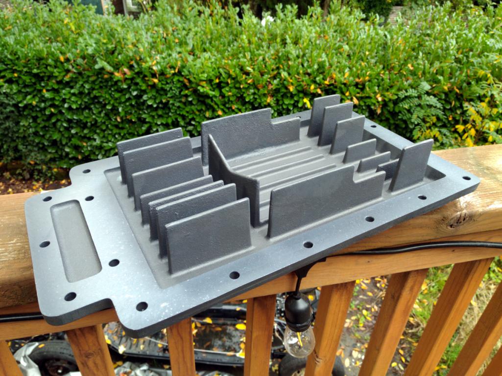
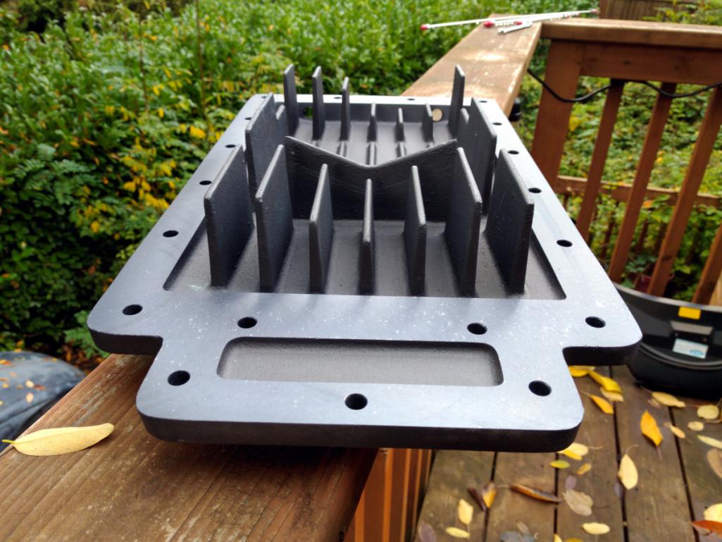
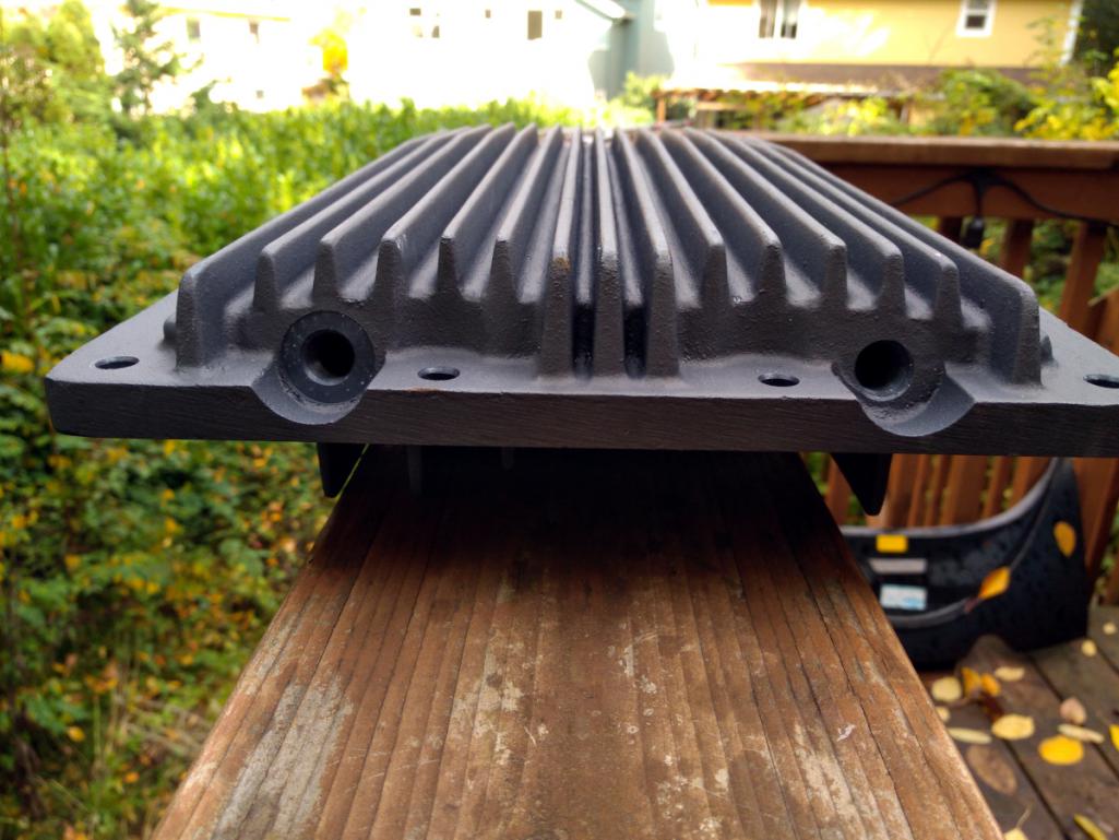
Posted by: Porschef Oct 29 2018, 06:56 PM
Nice, Marcus. Glad you're getting near the finish line with your engine.
One day while driving up to my sister's in Shelburne Falls, I took a different road and drove right past Clark's. Kinda wished I had stopped in, but at the time never thought about a Corvair engine as a potential power plant. Now, I do.
And yes, slop is a fun word...
Posted by: r3dplanet Oct 29 2018, 08:22 PM
I was actually thinking about "absorption" ..abZORBb... But "slop" has great onomatopoeia.
Anyway, yes. I'm eager to finish off this engine and start it up. The sooner the better.
-m.
Nice, Marcus.
Glad you're getting near the finish line with your engine. One day while driving up to my sister's in Shelburne Falls, I took a different road and drove right past Clark's. Kinda wished I had stopped in, but at the time never thought about a Corvair engine as a potential power plant. Now, I do.
And yes, slop is a fun word...
Posted by: DaveO90s4 Oct 30 2018, 05:35 AM
Hi Marcus. Good progress.
One of the selling points on my Otto (?) oil pan is that the external fins are angled to disperse heat away from the centre. Great. And then I put the engine in backwards into my 914 and defeat that. I hope it was just marketing hype. No such issue with you new pan. And my drain hole is not at the bottom. Must send you photos of my auxiliary oil coolers. Cheers. Dave
Posted by: Tdskip Oct 30 2018, 05:54 AM
But "slop" has great onomatopoeia.
Subscribing, I mean besides this being a cool build you used onomatopoeia on a car forum so I kind of have to subscribe.
Posted by: Dr Evil Oct 30 2018, 09:10 AM
I run an Edelbrock 4bbl currently on the 3.1 with a plenum with 6 runners. I had a set up for 140 heads, 4 runners, and oil heat using a Holley. Hated that Holley. My carbs are still not perfectly tuned, idle is all crap, but once it is going it is going. If I was keeping the vair power plant I was planning on weber 3bbl, but the plans have changed and i have jumped ship to join the Suby SVX camp for 240hp, heat, A/C, fuel injection. I still have a CIS setup that I modified to work on my vair (with the 3 port heads). Its in a box, maybe mess with it some day, needed tuning and leak checks. Im not even sure if I will keep the vair engine and tranz at this point.
I used the Otto oil pain and a deep pain on the power glide as well. I also ducted my exhaust forward to exit ahead of the buses rear wheels to help relieve some of the heat soak under and around the engine. The 914 naturally does this so the heat dissipation may be superior to stock corvair mounting and exhaust. I dont think you are gonna have heat issues, though. You have done so much to improve this over stock.
Posted by: sixnotfour Oct 30 2018, 10:04 AM
sucks about the oil pan the OG Otto stuff was nice..
Posted by: r3dplanet Oct 30 2018, 11:50 AM
Dave, I agree. For reasons that aren't clear to me I still prefer the Otto. Maybe because it matches the valve covers, or maybe because of the fit and finish. It's a clever design for sure. Who knows... if oil pan #2 ever returns I might install it. Answer is unclear at this time.
Hi Marcus. Good progress.
One of the selling points on my Otto (?) oil pan is that the external fins are angled to disperse heat away from the centre. Great. And then I put the engine in backwards into my 914 and defeat that. I hope it was just marketing hype. No such issue with you new pan. And my drain hole is not at the bottom. Must send you photos of my auxiliary oil coolers. Cheers. Dave
Posted by: r3dplanet Oct 30 2018, 11:51 AM
Hello, fellow wordsperson. If you're into fun words I urge you to have fun with my favorite word in the English language, "sesquipedalian." It's as giggleworthy as it is autological.
But "slop" has great onomatopoeia.
Subscribing, I mean besides this being a cool build you used onomatopoeia on a car forum so I kind of have to subscribe.
Posted by: r3dplanet Oct 30 2018, 11:57 AM
Which Edlebrock do you have? The 500? That still seems huge for 3.1 liters. I've had several of the Eddy 4-barrels and I generally really love them. In fact I think I have an extra 500 kicking around.
I'm still totes jelly of your Bus. Subaru power is obviously going to be better given than you're swapping '50s engine tech with '90s engine tech. I would have loved to see your Corvair engine come to fruition which is why you need to go get another Bus! Having two simultaneous car projects is always a great idea. ALWAYS
Speaking of .. my Barracuda is finally really to sell. I'll start crafting my ad for it.
I run an Edelbrock 4bbl currently on the 3.1 with a plenum with 6 runners. I had a set up for 140 heads, 4 runners, and oil heat using a Holley. Hated that Holley. My carbs are still not perfectly tuned, idle is all crap, but once it is going it is going. If I was keeping the vair power plant I was planning on weber 3bbl, but the plans have changed and i have jumped ship to join the Suby SVX camp for 240hp, heat, A/C, fuel injection. I still have a CIS setup that I modified to work on my vair (with the 3 port heads). Its in a box, maybe mess with it some day, needed tuning and leak checks. Im not even sure if I will keep the vair engine and tranz at this point.
I used the Otto oil pain and a deep pain on the power glide as well. I also ducted my exhaust forward to exit ahead of the buses rear wheels to help relieve some of the heat soak under and around the engine. The 914 naturally does this so the heat dissipation may be superior to stock corvair mounting and exhaust. I dont think you are gonna have heat issues, though. You have done so much to improve this over stock.
Posted by: gandalf_025 Oct 30 2018, 01:32 PM
One day while driving up to my sister's in Shelburne Falls, I took a different road and drove right past Clark's. Kinda wished I had stopped in, but at the time never thought about a Corvair engine as a potential power plant. Now, I do.
And yes, slop is a fun word...
Years ago I used to drive to Calvin Clark’s house to buy parts.
Once they moved to their current location, they frowned on walk
ins because the site wasn’t zoned for retail....
Mail Order only...
Posted by: sixnotfour Oct 30 2018, 02:13 PM
Attached image(s)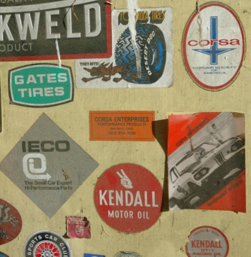
Posted by: r3dplanet Oct 30 2018, 02:19 PM
Very cool! It's a far cry from the never ending pile of SUMMIT RACING stickers.
Posted by: Dr Evil Nov 1 2018, 02:18 PM
Which Edlebrock do you have? The 500? That still seems huge for 3.1 liters. I've had several of the Eddy 4-barrels and I generally really love them. In fact I think I have an extra 500 kicking around.
I'm still totes jelly of your Bus. Subaru power is obviously going to be better given than you're swapping '50s engine tech with '90s engine tech. I would have loved to see your Corvair engine come to fruition which is why you need to go get another Bus! Having two simultaneous car projects is always a great idea. ALWAYS
Speaking of .. my Barracuda is finally really to sell. I'll start crafting my ad for it.
I run an Edelbrock 4bbl currently on the 3.1 with a plenum with 6 runners. I had a set up for 140 heads, 4 runners, and oil heat using a Holley. Hated that Holley. My carbs are still not perfectly tuned, idle is all crap, but once it is going it is going. If I was keeping the vair power plant I was planning on weber 3bbl, but the plans have changed and i have jumped ship to join the Suby SVX camp for 240hp, heat, A/C, fuel injection. I still have a CIS setup that I modified to work on my vair (with the 3 port heads). Its in a box, maybe mess with it some day, needed tuning and leak checks. Im not even sure if I will keep the vair engine and tranz at this point.
I used the Otto oil pain and a deep pain on the power glide as well. I also ducted my exhaust forward to exit ahead of the buses rear wheels to help relieve some of the heat soak under and around the engine. The 914 naturally does this so the heat dissipation may be superior to stock corvair mounting and exhaust. I dont think you are gonna have heat issues, though. You have done so much to improve this over stock.
If Eddy has a 360, that is the one I have. If not, then its slightly bigger. Im going off of memory. It was nice to install, quick adjust, go. Jetting changes dont take a whole lot of work like the Holley. I may get another bus someday....but I have lost real estate and have no space in my new suburban palace.
Posted by: r3dplanet Nov 1 2018, 06:26 PM
Hmm. Shoot a pic of it? The smallest Eddy is 500cfm. Now I'm curious.
-m.
Which Edlebrock do you have? The 500? That still seems huge for 3.1 liters. I've had several of the Eddy 4-barrels and I generally really love them. In fact I think I have an extra 500 kicking around.
If Eddy has a 360, that is the one I have. If not, then its slightly bigger. Im going off of memory. It was nice to install, quick adjust, go. Jetting changes dont take a whole lot of work like the Holley. I may get another bus someday....but I have lost real estate and have no space in my new suburban palace.
Posted by: r3dplanet Nov 1 2018, 06:43 PM
Okay. Finally the simple task of installing the oil pan is finished. My friend Ben dropped by and we tilted the engine onto another work table. The table is unhappy about the load.
Any oil pan for the Corvair is not ideal In order to gain ground clearance, the pan is really more of a lid. Most of the oil sits above the gasket line so it can leak just sitting there. That is, it could leak out most the oil in total if given the chance. That's why I'm extra particular about the mating surfaces and sealing. I'm trying to avoid a hypothetical situation where it leaks a parking lot, then someone will point and laugh at me because of the Corvair engine. Then I'd pee my pants to complete the spectacle.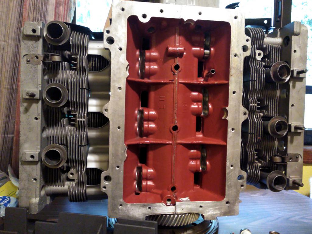
Dry fitting the pan showed another problem. One of the baffles inside the pan butted against one the casting ribs on the bottom of the engine case. It could be a universal application fit, I'm not sure. Anyway a little quick work with the grinder and a file and I removed a little square. It only wanted a 1/4" removed, but the grinder fit easier this way.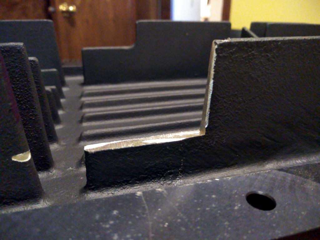
And here's the Otto oil pickup. It's a decent improvement over stock and it fits this oil pan perfectly. I've mentioned it before but here it is again anyway.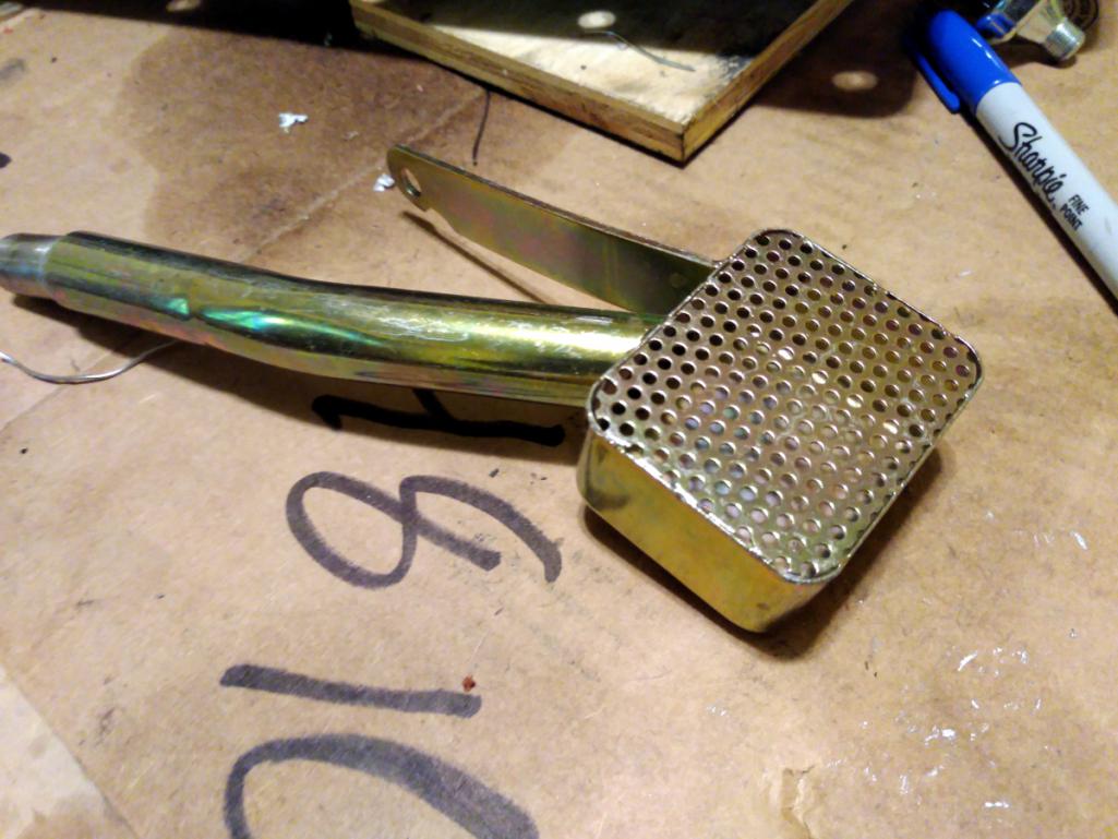
Installed: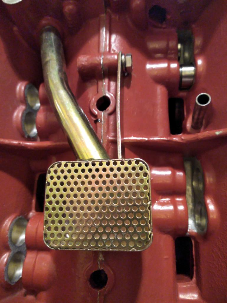
Now it's finally time to clean the surfaces and install the pan. As per usual I cleaned both mating surfaces with white coffee filters. First with mineral spirits, and then with alcohol. The gasket I'm using is a thin felt-rubber gasket. I'm not sure if this is the best choice but if it doesn't work I have other, thicker gaskets.
I doubt I really needed to use any gasket dressing given that the surfaces are flat, but they're not perfectly flat. So I used a bit of Gasgacinch, let it dry, and slapped it onto the pan. Then it's right back onto the engine.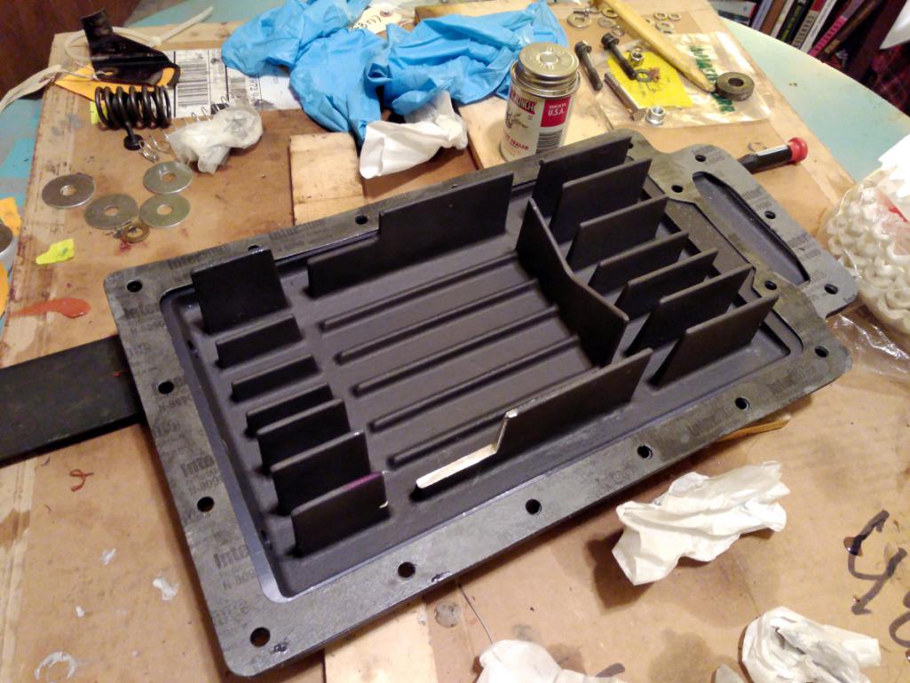
After letting it sit overnight I realized that I forgot to apply anti-seize. So I popped each off one at a time and torqued them to 70 INCH pounds in a criss-cross pattern. The manual says 100 inch pounds, but that's a mistake. The actual value is 60-84.
Anyway, done. Next up are the lifters, pushrods, rockers.
Blam!
Attached thumbnail(s)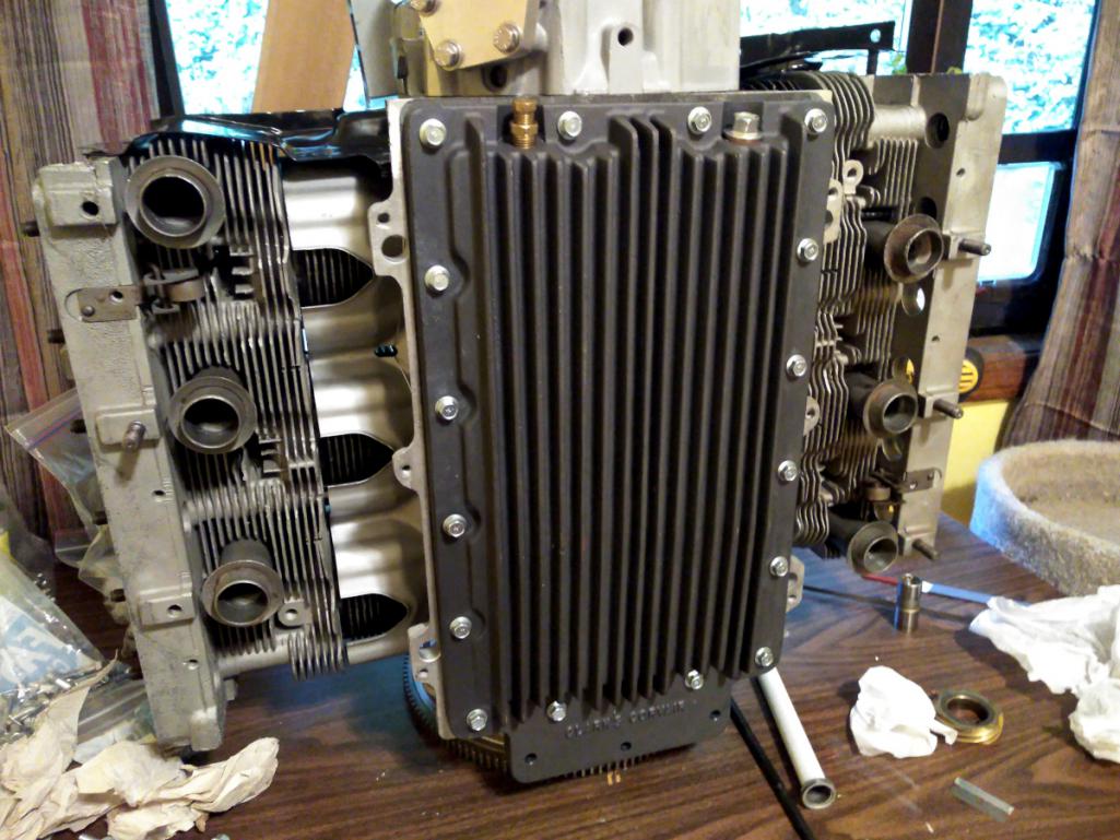
Posted by: sixnotfour Nov 9 2018, 03:44 AM
Marcus, hows it going ?
some Corvair humor.. 42 yrs ago
me 16yrs old ..first set of radial tires ..used of course, and my Dad
Attached image(s)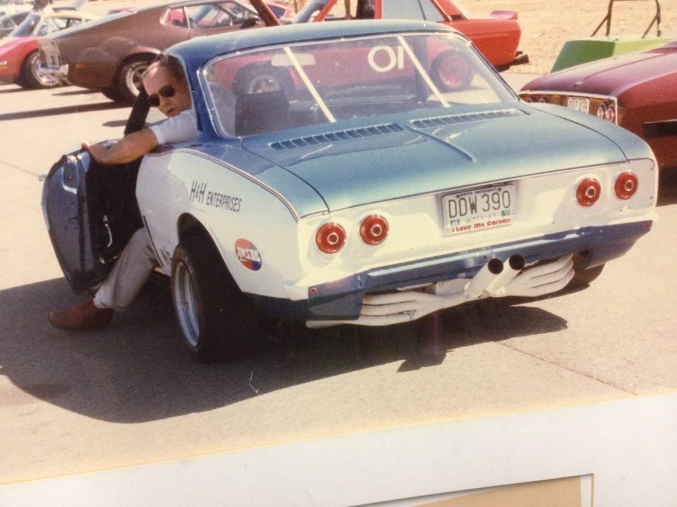
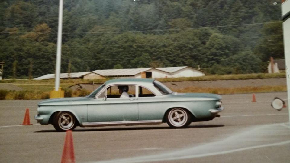
Posted by: Maltese Falcon Nov 10 2018, 05:13 PM
Friend of ours restoring this one, features a smallblock Chev with a period correct Crown conversion kit. I dig the velocity stacks in the back seat 
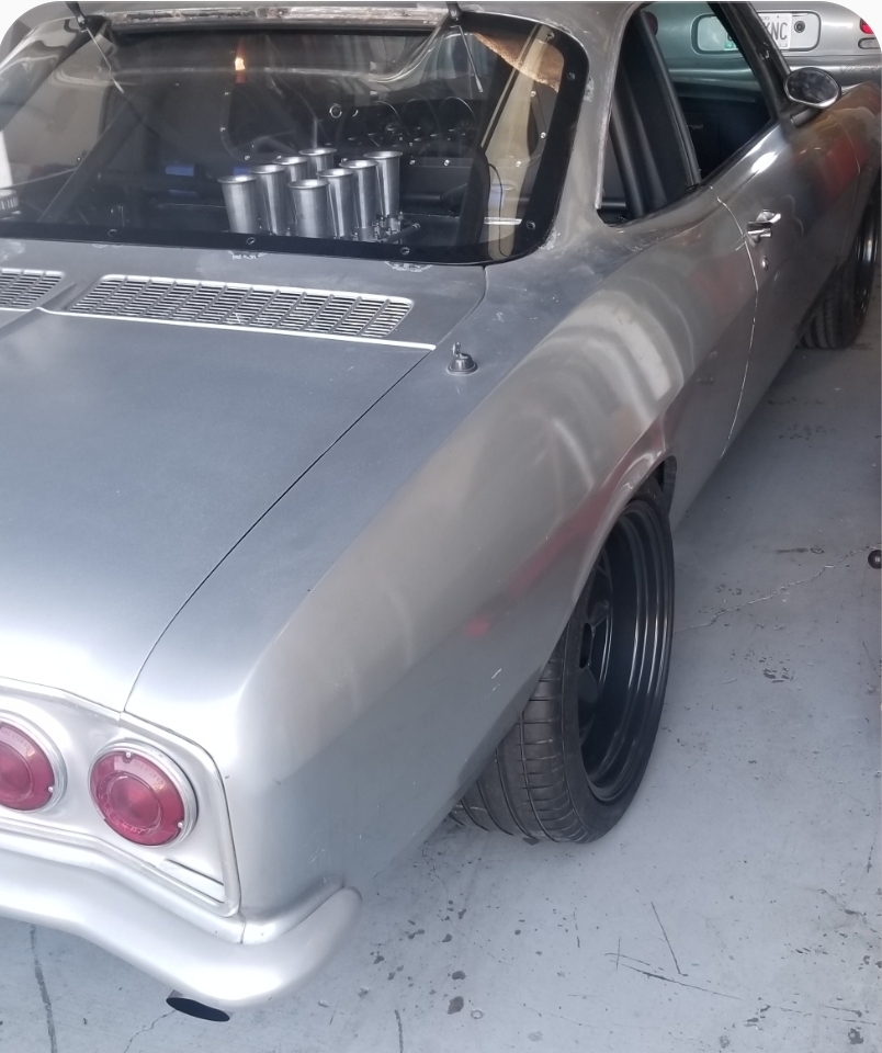
Posted by: r3dplanet Nov 10 2018, 07:22 PM
Malt and Six:
Sweet rides! Those are both very pretty cars. I'm reasonably jealous.
Six- I prefer the earlier Corvairs to the later ones in terms of looks. Just really like the lines and classiness of the body. But Malt, those velocity stacks are sexy. And I like that the engine is right where it is supposed to be - amidships.
I'm in and out these days. But I've been piddling about on a stupid oblique side project that will help finish the engine assembly. Mostly playing with putty. More on that in a day or two.
-m.
Posted by: Maltese Falcon Nov 11 2018, 12:45 AM
...also built this set of racing headers for the same guy, but another one of his Corvairs; this one has a hot rod 6cyl. !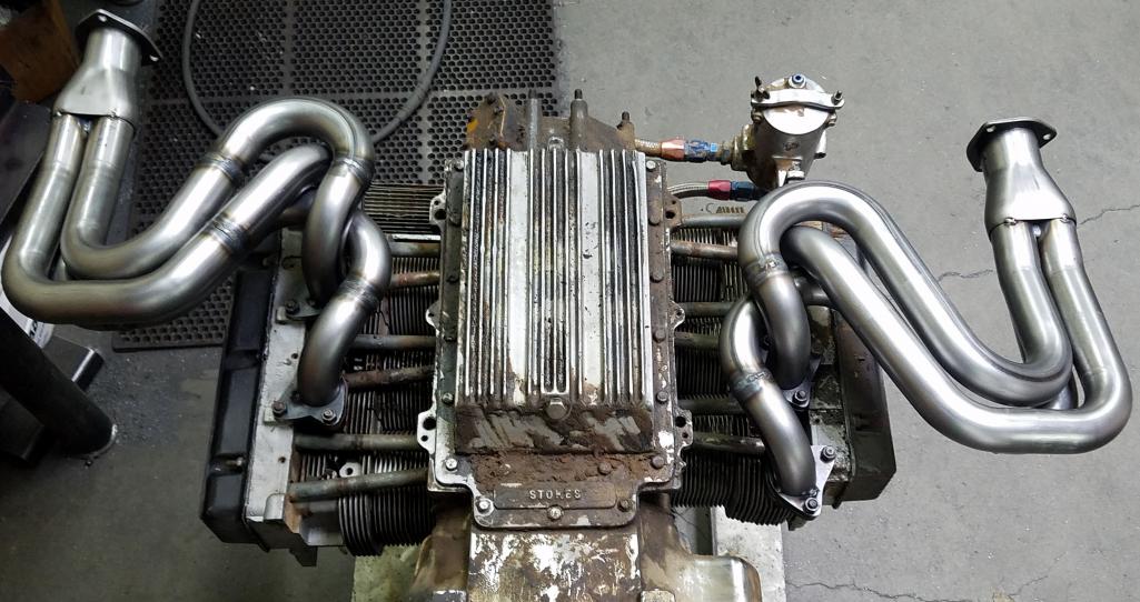
Posted by: sixnotfour Nov 11 2018, 01:40 AM
angled exhaust ports ?...otto
Attached image(s)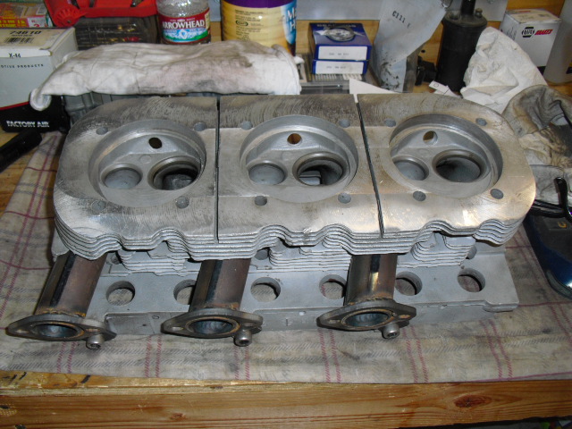
Posted by: sixnotfour Nov 11 2018, 02:28 AM
I had early turbos ,dad had later..
i liked the early body
Attached image(s)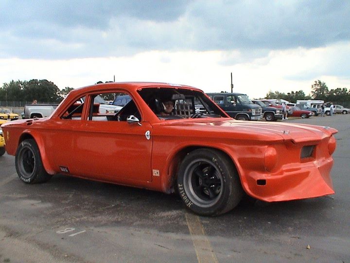
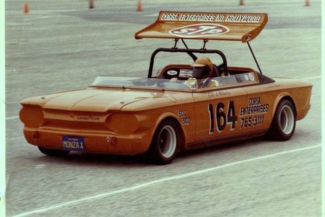

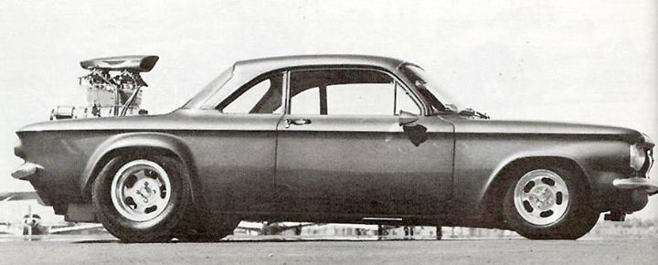
Posted by: r3dplanet Nov 12 2018, 06:45 PM
David brought up a point at exactly the right moment. The heat shields that lay underneath the cylinders are not exactly the same. There's an oval hole in one of them that here-to-fore I thought was to make way for the dipstick tube. Although I never did give it much thought at all. Then I went to install it and found that the hole is on the oppose side of the dipstick tube. Whaaaa?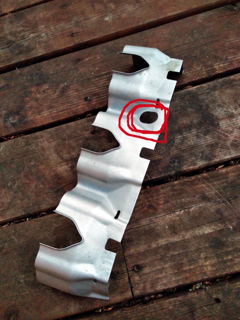
The dipstick doesn't need a hole in the shield. That hole is only for '60-'62 cars that used a crankcase pressure relief tube to dump crankcase gasses underneath the car and out into the atmosphere. Nice. Starting in '63 GM started using a PCV valve instead. Long ago one could buy a plug for the hole but I'm not sure from which material it was made. I am sure that the plug is right next to the exhaust so if it were made of rubber it wouldn't last.
At first I was inclined to make a high-temp JB-Weld sandwich with a little bit of steel sheet. But then I decided to do a little experiment. Or rather, three at once. I wanted to see if I could weld a patch on the very thin shield sheet metal (I can't) and if such a patch could be powder coated on an otherwise already coated part. Long ago I coated the heat shields in high temp silver exhaust powder. I've never re-coated a piece, so why not? I also want to try out using Alvin's Hi-Temp Lab Metal. It's a high metal content putty that's supposed to withstand high temperature and is able to be powder coated.
Here's a little montage of the process. I cut a little oval patch and tried and failed to weld it in, but just burned right though the shield. I should have known but did it anyway. Then I had to cut another little patch and then puttied it all into place with the Lab Metal. After sitting for 24 hours the instructions say to bake it at 425F, which is exactly the powder coating temperature. I powder coated it with the same powder and baked it. 
It looks terrible and I blame myself for the shoddy work. But the experiment was a a reasonable success. While being the opposite of pretty, the patch is strong and good to at least 450F (Alvin says a 1000F). The powder doesn't look great but it did the job. My plan, in its entirety, is to install and let someone else check the results at the next disassembly.
Here's the final product. It's PERFECT.
/snark
Posted by: r3dplanet Nov 12 2018, 06:56 PM
Right. Let's install the pushrod tubes.
A while back I made a little jig to prep the tubes. I coated the exterior in the same high temp silver powder as the heat shields and then painted them with a few coats of high temp ceramic paint in white. The ends are polished with my rotary tool to prevent damage to the seals.
The tubes get a Viton seal on each end of the tube, but the engine case side of the tube goes in through the head naked. Once through the head the seal is popped on and coated in engine oil. Then the tube can be shoved all the way in to the bore. I used a nylon hammer and a 16mm socket to drive them in all the way, as per the service manual instructions.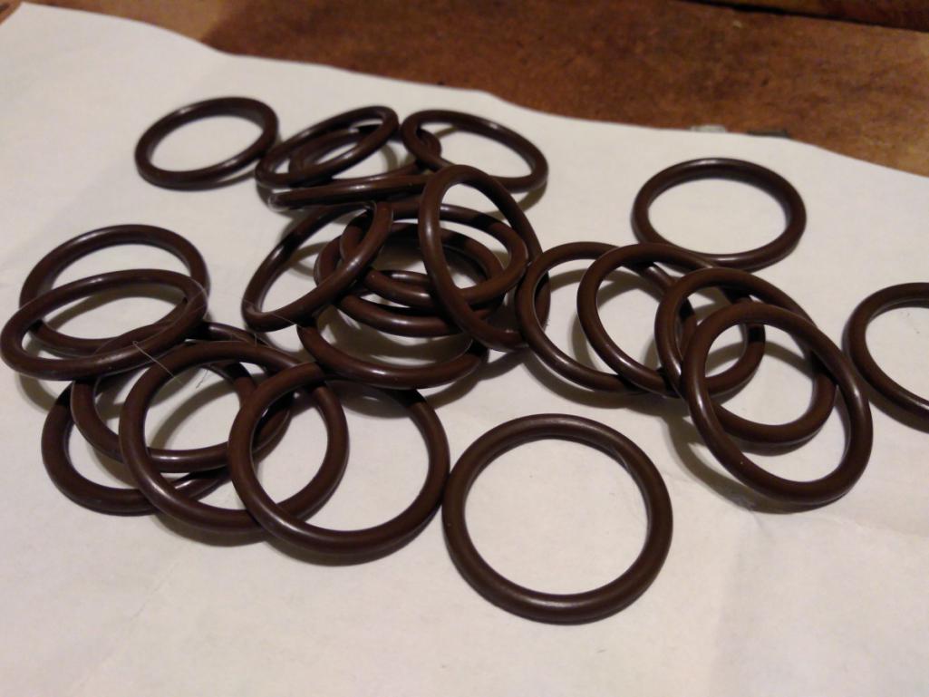
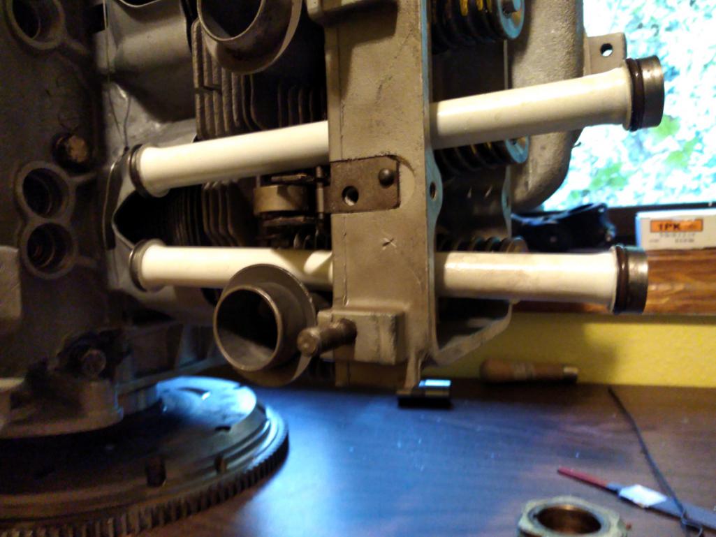
Note the orientation of the tube. The manual calls the case side the "long side of the tube." Odd way to describe one end of a tube, but okay. You can see in this photo that the ends are different. The larger end goes into the head.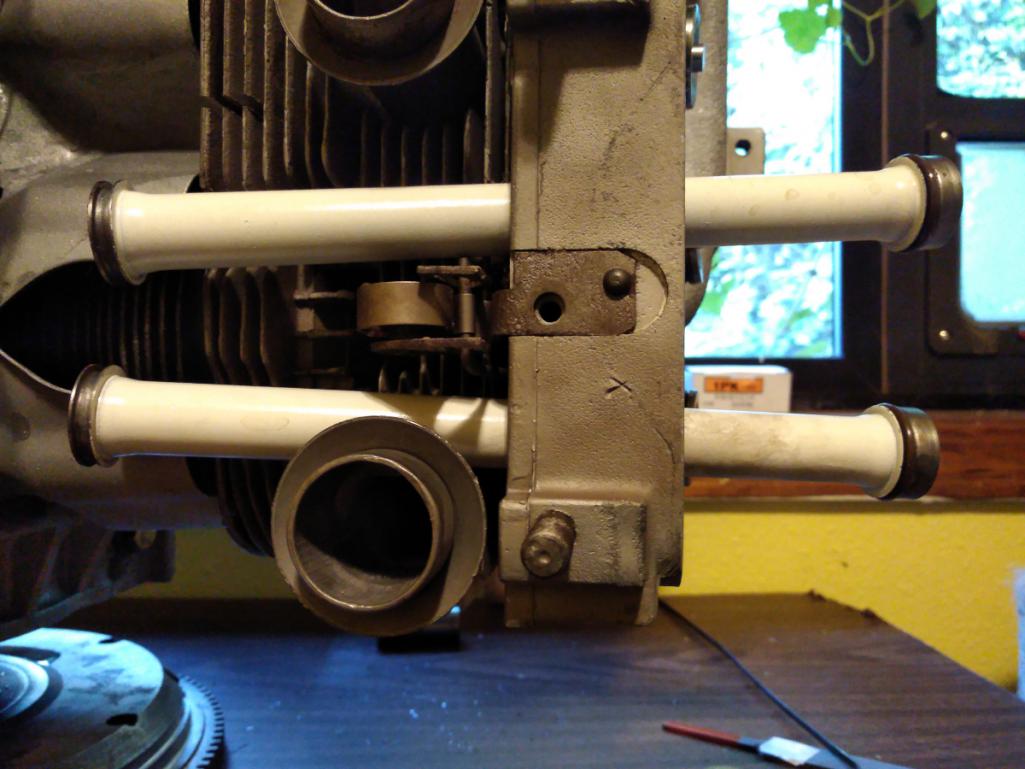
Here are all twelve installed: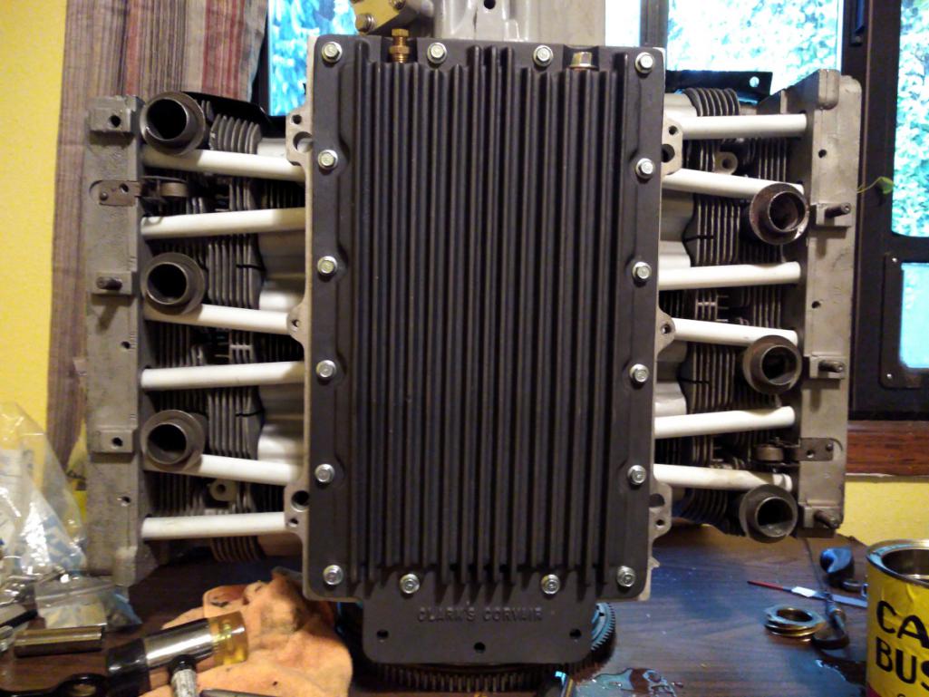
Posted by: DaveO90s4 Jan 12 2019, 03:45 AM
Hi Marcus,
What’s up?
Cheers
DaveO
Posted by: r3dplanet Jan 13 2019, 01:45 AM
Hey gang. I'm not well. Struggling through my days and anxious to sell off my cars and junk. I need to get the 914 put back together so I can sell it off, hopefully this Spring. After it's gone I'll have space to transfer the Corvair engine (somehow) from my spare bedroom down two flights of stairs to the garage and attempt to start it up. Once I'm convinced that the engine is worthy it will go to a new owner - perhaps somewhere in the warm land of Australia.
I guess the only news I have is that the engine is complete except for a couple of ancillaries and lower sheet metal. I finished up with the rocker assemblies and static valve adjustment. I'm worried that it takes a bit of force to spin the crank, but we'll see what happens. Photos were taken and I can make a new post showing all that. Just need to get the energy to get of my ass.
Sincere apologies for the delay. Getting an energy burst is very rare. I'm envious of people with energy.
Anyone want a 914? Or a Barracuda?
-m.
Posted by: Jason74914 Jan 13 2019, 06:41 AM
So sorry to hear you are not feeling well. I went through quite an ordeal last year, so I can relate to the thirst for energy! Hang in there.
It is quite a trek to Oregon, but I would like to hear more about your Cuda. Message me and I will give you my email. Looking for another project...in addition to my 914!
Jason
Posted by: euro911 Jan 13 2019, 03:40 PM
Hoping to hear you health issues are just a temporary setback, Marcus.
Posted by: BIGKAT_83 Jan 15 2019, 04:35 PM
This guy might have a corvair engine for sale. All Porsche 993 awd running gear and interior in this Corvair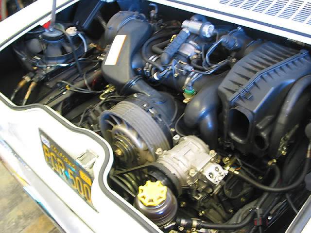
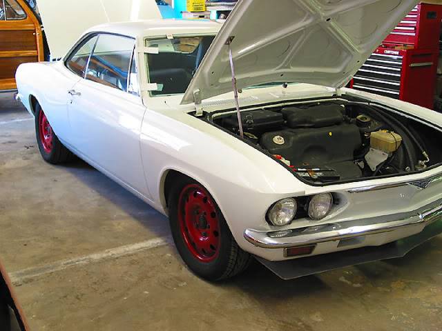
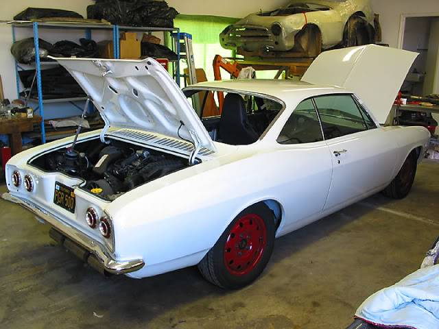
Posted by: r3dplanet Jan 15 2019, 10:37 PM
This guy might have a corvair engine for sale. All Porsche 993 awd running gear and interior in this Corvair
That's pretty sweet. I would like to have witnessed that project. I'm a huge fan of the unholy.

Posted by: euro911 Jan 16 2019, 01:05 AM

Posted by: rick 918-S Jan 17 2019, 03:34 PM
Sorry to read about your health issues. I will miss checking into this thread if you end up having to sell off the project. Take care of number one first. I too have a history with the Corvair. I have owned Early and Late coupes and verts. Here is one of mine.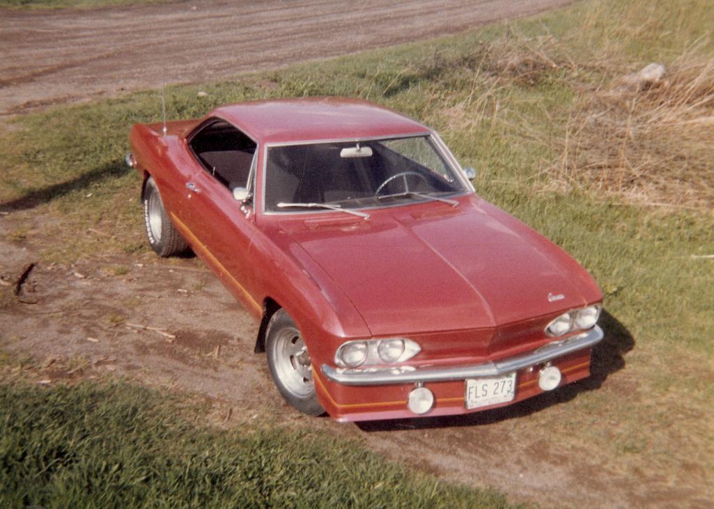
Posted by: sixnotfour Jan 17 2019, 04:53 PM
https://youtu.be/iWcMrWk_0Uw
bad press for the Corvair
Posted by: sixnotfour May 18 2019, 11:26 AM
Hey Markus,
@http://www.914world.com/bbs2/index.php?showuser=8671
Posted by: sixnotfour May 18 2019, 11:54 AM
Attached thumbnail(s)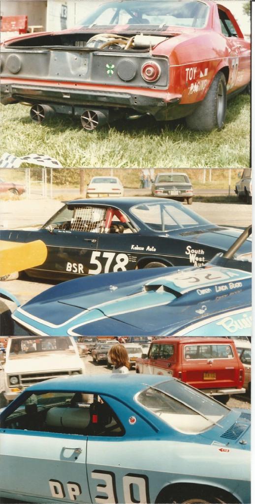
Posted by: sixnotfour May 18 2019, 12:02 PM
Attached thumbnail(s)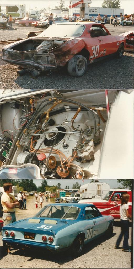
Posted by: sixnotfour May 18 2019, 12:20 PM

Attached image(s)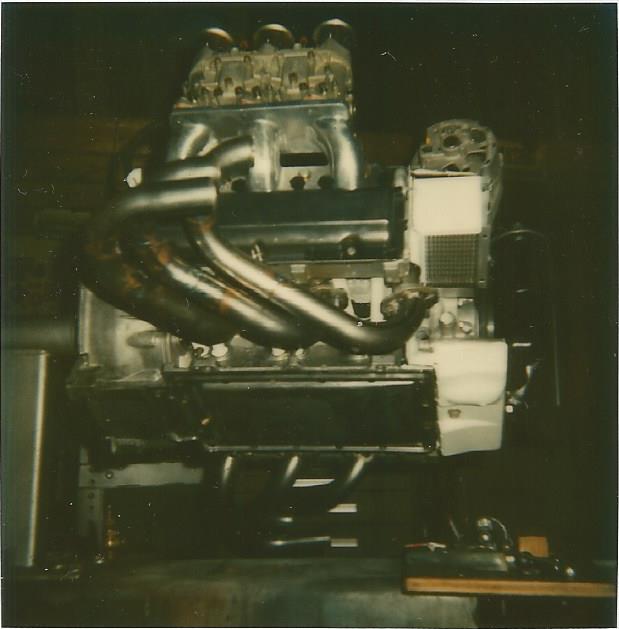
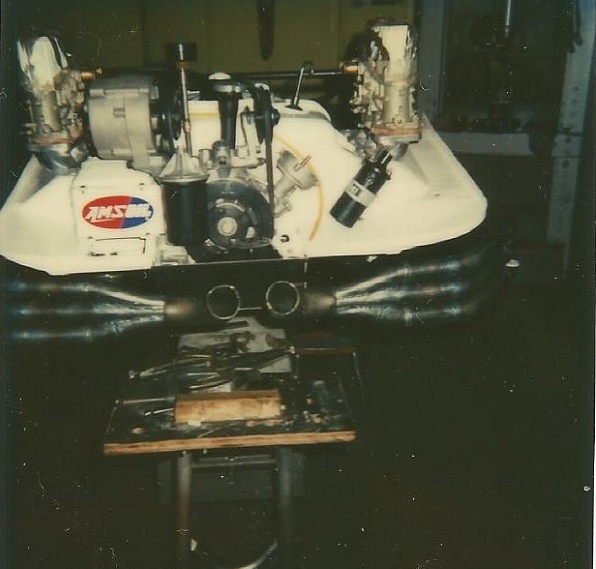
Posted by: r3dplanet May 18 2019, 12:28 PM
I love those vintage pics. Looks like a fun day! Except for that fire, I mean.
I apologize for the long delay on this project. All that's left is to get a pair of lower shrouds and thermostats. The engine is otherwise mostly complete. Need a pulley setup like what David has. I have another problem where I built it in a spare bedroom and need to get it down to the garage. Somehow I need to figure out a brains-to-muscle ratio and get some help moving down a bunch of stairs. Or out the window and around the yard. Something.
The order of operations here is that my 914 is almost ready to go. Once it can move on its own power I can make room in the garage. But I'm very excited to figure out a way to move the engine and see if it will start.
Soon. All I can say is soon.
Posted by: r3dplanet May 18 2019, 12:34 PM
Wow. That's a sweet setup. Triple carbs and headers. Still in an overall compact package. Beautiful!
Posted by: sixnotfour May 18 2019, 12:34 PM
Glad to hear from you... Ya my mom sent me a huge box of photos, been fun ..looking back ....simple times .....I know some one who is dreaming of a Corvair powered 914..
You may hear from him
Posted by: sixnotfour May 18 2019, 12:36 PM
Wow. That's a sweet setup. Triple carbs and headers. Still in an overall compact package. Beautiful!
That was in my Dads shortened Stinger look alike
Posted by: sixnotfour Sep 6 2019, 02:40 AM
Attached image(s)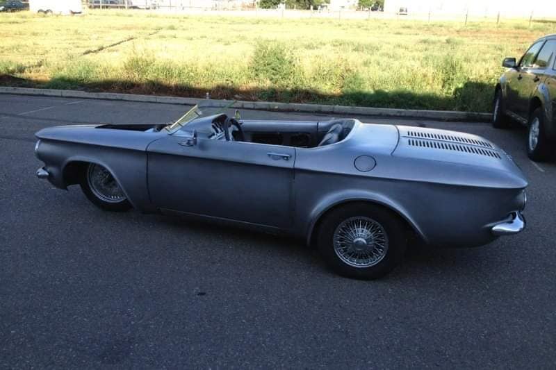
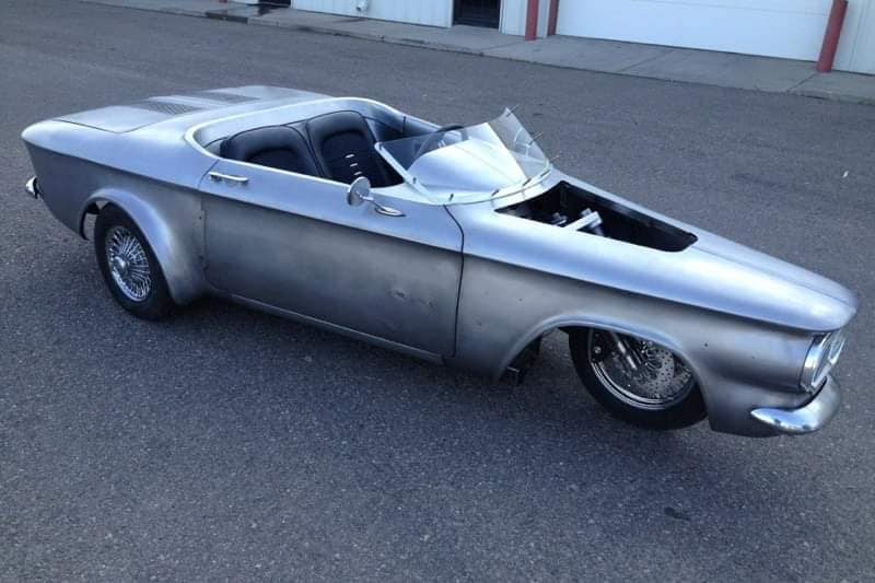
Posted by: Tbrown4x4 Sep 6 2019, 03:00 AM
Dammit. I was hoping to hear how Marcus was doing. Anyone hear from him lately?
@http://www.914world.com/bbs2/index.php?showuser=4741
Posted by: 76-914 Sep 6 2019, 08:53 AM
I was thinking of him yesterday.
Posted by: r3dplanet Sep 7 2019, 10:34 PM
Hello gentlemen.
Thank you for the warm thoughts. As many of you have guessed I'm not doing all that great. My remaining kidney is not doing well, creatinine levels are in the 4s. I'm slow, weak, dizzy. Some days I have good energy but most days I'm flattened out. I've lost 30 pounds over the summer and my docs don't like that one little bit. But hey, on the plus side - new pants! I'm okay for now but we're all on the same page as to where this is leading. I'm totally off treatment now - no chemo, no dialysis, no steroids, no blood infusions, nothing. Just winging it. That's the new medical plan: winging it. My nephrologist gave me the hospice speech last Thursday but I think that's still at least another year off. Hooray! I plan to make all that planning-for-the-inevitable stuff yet another project. There always needs to be a project.
Some notes on the Corvair engine project:
I have a suspicion that I need to take the engine back apart because it seems to me a little tight bolted altogether. It meets spec for torque to rotate the crankshaft. It just isn't quite as free as I would like it to be. Both me and two machinists inspected the main bores and they were all fine, pre and post bearing install. Maybe I'm just imagining it. Or it could be that the case wants an align-bore. Tom Stark the machinist didn't seem to think so. I'm 50/50 on popping it apart because I have no real way of measuring bore alignment.
The main note is that I can't take the project any further. I'm just too weak. Next year I'll be selling my 914 and all of the bits that go with it. At this stage in my life I need cash more than projects. I just want to drive the 914 next spring/summer as much as I can and then maybe sell it in the autumn. But hopefully I can sell off the Corvair bits for someone else to continue the project. I'd like to get out of what I put into it money wise, minus the labor as is my way. I'd really like to see someone finish the engine, install it, and run it. That's been the plan the whole time, but I need to hand it off to someone else as nerdy as I am about this stuff.
It's all sitting in my spare bedroom, almost entirely completed. It just stares at me with disappointment every time I dawdle in there. I'm sorry for the let-down and for taking so long to get back to all of this. These days the Corvair engine is about the last thing on my mind.
So... who wants to pick up my obsessive little engine? Bring a friend.
Now that I'm wrapped up with it I'll reveal a little secret. Half the point for me to build this engine was really a roundabout way to have a 914 and never have to adjust the valves again. Ta-da!
Posted by: 76-914 Sep 7 2019, 10:48 PM
You're an inspiration. More important than any car is the courage you display. At some point in the not to distant future I will remember your words and attitude and draw strength from them.
Posted by: Tbrown4x4 Sep 8 2019, 12:22 AM
Thanks for updating us Marcus. Sorry to hear of your troubles.
When a new engine is assembled, it can be difficult to turn by hand. I've always been told to put a new starter on any new engine because the extra effort required can finish it off. That means unhappy customer.
The level of care you have used building this engine, I'd be surprised if something was wrong with it.
I'll let YOU in on a little secret: I drive my 914 almost 100 miles a day, and I will NEVER stop hating valve adjustment time!
Our prayers are with you
Posted by: DaveO90s4 Sep 8 2019, 06:01 AM
Hi Marcus - it would seem that people all over the place have had you in their minds lately. I would like to think I would be able to adopt your approach in a similar situation. Not sure I could - but would like to think so.
I’ve been incommunicado of late - have been flat out (New Zealand, China. Japan) trying to retire but failing miserably! Must write properly this coming week.
Now 914world, who is going to grab Marcus’ gem of an engine for their 914? I have put a reverse rotation Corvair engine in my 914 and have learnt a lot on the way. I would be only too pleased to assist from afar (Australia) if anyone buys Marcus’ engine. I have the designs for the engine mounts that I can share, a few tricks about other bits and pieces, eg gearbox mounts, and I have a really nice specially designed fan belt pulley that I could provide to the new owner (which is proven on my car and which I think is essential for a reverse rotation engine). Anyway, you get the gist. You buy Marcus’ engine and I will pass on all that I have leaned in putting one of these engines in to a 914.
Or else I will have to buy it myself - but I’m trying to retire, remember.
Will email you later this week Marcus.
Cheers
DaveO
Posted by: euro911 Sep 8 2019, 09:10 AM
Really sorry to hear this Marcus. I agree that your attitude is inspirational and glad to see that you still have a sense of humor. I have a saying ... laughter is the best medicine that that isn't prescribed often enough.
I keep telling my wife the reason I have so many projects is so I always have something to look forward to
Hang in there. I wish you the best and pray that divine intervention will come your way.
Posted by: sixnotfour Sep 8 2019, 09:46 AM
@http://www.914world.com/bbs2/index.php?showuser=8671 wants a corvair engine.....
Good to hear from you Marcus,
Posted by: Tbrown4x4 Sep 8 2019, 10:17 AM
A Corvair engine is the only engine swap I would consider. Can't afford a Porsche 6, and have had many Corvairs over the years. My son currently has a '66 with a 110/automatic in it. I don't want to cut up the car for radiators and intercoolers.
I would love to pick it up and help you out, but I'm still recovering from my daughter's wedding. (Financially, I mean. The hangover is long gone!)
I hope a World member can keep this going for you.
Posted by: r3dplanet Sep 8 2019, 10:34 PM
Hey gang, not to worry. After all, a world without me is not a world where I want to live.
I have my last words figured out just in case. My plan is to spin a yarn to whoever might be present about how I stashed away thousands of dollars in a secret location. "The money.. " I'll gasp, "The money is in the ... [croak]." There's no reason why it can't be funny. Everything is funny from the right perspective.
Anyway, I'm touched by the kindness. 914world is the best auto forum on World Wide Web. You guys are the best.
Posted by: r3dplanet Sep 8 2019, 10:36 PM
Oh man, I'll bet the dowry was sizable. Presumably a goodly amount of livestock and acreage isn't cheap, not to mention the magic jewels. No idea how you manage.
@http://www.914world.com/bbs2/index.php?showuser=8671 wants a corvair engine.....
Good to hear from you Marcus,
Posted by: JRust Sep 8 2019, 10:42 PM
Dang Marcus sorry to heart things are going so bad health wise. I applaud your spirit though. I've almost got mine back on the road. I'll try to pick a good day & we can go grab lunch in it
Posted by: r3dplanet Sep 8 2019, 10:44 PM
Retirement? What's that? It sounds nice despite the sinister overtones of the word. You should retire somewhere with a huge garage and shop ... for reasons. Clearly only a gentleman of quick mind, sound judgment, and reasonable fabrication skills should inherit my project. Ownership of a well used shop goes without saying.
*cough*
Hi Marcus - it would seem that people all over the place have had you in their minds lately. I would like to think I would be able to adopt your approach in a similar situation. Not sure I could - but would like to think so.
I’ve been incommunicado of late - have been flat out (New Zealand, China. Japan) trying to retire but failing miserably! Must write properly this coming week.
Now 914world, who is going to grab Marcus’ gem of an engine for their 914? I have put a reverse rotation Corvair engine in my 914 and have learnt a lot on the way. I would be only too pleased to assist from afar (Australia) if anyone buys Marcus’ engine. I have the designs for the engine mounts that I can share, a few tricks about other bits and pieces, eg gearbox mounts, and I have a really nice specially designed fan belt pulley that I could provide to the new owner (which is proven on my car and which I think is essential for a reverse rotation engine). Anyway, you get the gist. You buy Marcus’ engine and I will pass on all that I have leaned in putting one of these engines in to a 914.
Or else I will have to buy it myself - but I’m trying to retire, remember.
Will email you later this week Marcus.
Cheers
DaveO
Posted by: r3dplanet Sep 8 2019, 10:45 PM
Hells yes we should. I eat light.
Dang Marcus sorry to heart things are going so bad health wise. I applaud your spirit though. I've almost got mine back on the road. I'll try to pick a good day & we can go grab lunch in it
Posted by: r3dplanet Sep 8 2019, 10:48 PM
Thanks! I appreciate your help in keeping interest in this project alive. This is a very much "it takes a village" time for me.
@http://www.914world.com/bbs2/index.php?showuser=8671 wants a corvair engine.....
Good to hear from you Marcus,
Posted by: r3dplanet Sep 8 2019, 10:53 PM
I agree! We're the kind of people that feel better knowing that something cool is coming down the pipe. A trip to make, a project to plan, consumables to buy. I think it creates a sense of the necessity of fulfillment. As in, hey I made these plans so I have to follow through somehow. It's good for continuity.
Really sorry to hear this Marcus. I agree that your attitude is inspirational and glad to see that you still have a sense of humor. I have a saying ... laughter is the best medicine that that isn't prescribed often enough.
I keep telling my wife the reason I have so many projects is so I always have something to look forward to
Hang in there. I wish you the best and pray that divine intervention will come your way.
Posted by: DaveO90s4 Sep 9 2019, 04:28 AM
Hey Marcus, in response to your black joke about last words, I thought you might be amused by the following - but you probably know this already. (I’m quite attracted to the words “Wow, what a ride”.)
“Spike Milligan's gravestone quip is nation's favourite epitaph. With the immortal words, 'I told you I was ill', carved onto his tombstone, he undoubtedly got the very last laugh. And now comedian Spike Milligan's famous epitaph has been named the nation's favourite.”
Anon
DaveO
Posted by: r3dplanet Nov 2 2019, 04:15 PM
Alright gang, the project is now for sale.
http://www.914world.com/bbs2/index.php?showtopic=341485
Hale and hearty will be the inheritor.
Posted by: sixnotfour Nov 2 2019, 04:33 PM
@http://www.914world.com/bbs2/index.php?showuser=8671
"Hale and hearty will be the inheritor."
Posted by: 914werke Aug 7 2020, 10:31 PM
@http://www.914world.com/bbs2/index.php?showuser=4741

Posted by: r3dplanet Aug 7 2020, 11:21 PM
Ha. I suppose I deserve a poke to the face. My cat certainly thinks so.
Sitrep: nobody bought the engine project or even made an offer. Soon I'll have to move out of here and find a smaller place to live. I have to downsize considerably and that means purging most of my cars. The future for the Corvair engine that festoons my living room looks poor. I was *really* hoping to hand off the project to someone else. Now I'm considering just scrapping the engine entirely.
I'm putting the Barracuda up for sale next month. Hopefully it bring in enough to finish the body work on my Beetle. Covid times are bad times to sell sexy Mopars but that's out of my control. That will at least drop my car stable from five to four.
The 914 sits sad alone in the garage for yet another year. I need to find someone who can do engine work and fix the fifty leaks on the 1911 engine after it was "assembled" by a "professional." I just don't have it in me to keep hacking at it. Time to find a good mechanic! I don't want to sell the 914 but I may have to do just that. We'll see. Too early to know at this point. I'd rather hold on to it.
In the springtime I was super sick until mid-May. I'm much better now but have lots of bone pain and weakness. The thought of rolling around the garage floor juggling gearboxes no longer holds any allure for me so the sooner I purge my heavy car projects, the better. I'm happy to be vertical and in good spirits though. It's nice to report good health news for once, not that anyone asked.
So... any takers on a cheap Corvair engine project?
Posted by: djway Aug 7 2020, 11:58 PM
Ha. I suppose I deserve a poke to the face. My cat certainly thinks so.
Sitrep: nobody bought the engine project or even made an offer. Soon I'll have to move out of here and find a smaller place to live. I have to downsize considerably and that means purging most of my cars. The future for the Corvair engine that festoons my living room looks poor. I was *really* hoping to hand off the project to someone else. Now I'm considering just scrapping the engine entirely.
I'm putting the Barracuda up for sale next month. Hopefully it bring in enough to finish the body work on my Beetle. Covid times are bad times to sell sexy Mopars but that's out of my control. That will at least drop my car stable from five to four.
The 914 sits sad alone in the garage for yet another year. I need to find someone who can do engine work and fix the fifty leaks on the 1911 engine after it was "assembled" by a "professional." I just don't have it in me to keep hacking at it. Time to find a good mechanic! I don't want to sell the 914 but I may have to do just that. We'll see. Too early to know at this point. I'd rather hold on to it.
In the springtime I was super sick until mid-May. I'm much better now but have lots of bone pain and weakness. The thought of rolling around the garage floor juggling gearboxes no longer holds any allure for me so the sooner I purge my heavy car projects, the better. I'm happy to be vertical and in good spirits though. It's nice to report good health news for once, not that anyone asked.
So... any takers on a cheap Corvair engine project?
I wish I could. It is a piece of art at minimum.
Posted by: sixnotfour Aug 8 2020, 08:59 AM
@http://www.914world.com/bbs2/index.php?showuser=8671
Hi Marcus....this kid got a GF and now is a dreamer...DangIt
Posted by: euro911 Aug 8 2020, 10:59 AM
Awesome Motor, Marcus, but I already have two 911 motors, a 912 motor and a 914 motor taking up much needed space in my garage (in addition to many boxes of car parts yet to unpack). Recently sold my wife's '99 Beetle and planning to sell my '96 Tacoma, but that still leaves us with 8 other 4-wheeled vehicles
Somebody out here needs to buy it though
Posted by: DarkMonohue Aug 8 2020, 11:17 AM
I have no money, no time, no space, and no spousal permission. But this is a rad engine and I have wanted a Corvair for thirty years. And I live a hundred miles from Marcus.
Someone please delete this thread before I embarrass myself.
Powered by Invision Power Board (http://www.invisionboard.com)
© Invision Power Services (http://www.invisionpower.com)