Printable Version of Topic
Click here to view this topic in its original format
914World.com _ 914World Garage _ My 2.4 Six Engine
Posted by: McMark Jul 15 2013, 07:30 PM
I picked up this 2.4 six awhile back and I'm gonna use this thread as I develop the engine which will eventually go in my gold car.
I'm starting a little out of order, but too bad. 
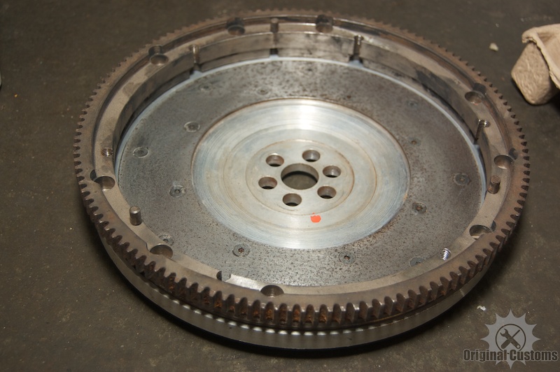
So I have this aluminum flywheel. No manufacturer stamps or numbers on it whatsoever. I'm thinking that it might be too light for a street car, so I may not use it. It's about 3lbs by itself. I've got a 914 clutch adapter (basically a cut down 914/4 flywheel that bolts to the outer edge) and that brings the total flywheel weight to about 10lbs.
I want a streetable car, is this thing too light?
Attached image(s)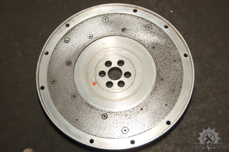

Posted by: ConeDodger Jul 15 2013, 07:37 PM
Try it...
Posted by: BKLA Jul 15 2013, 07:47 PM

I have a lightened Patrick Motorsports flywheel on a 2.4 that I'm building. Its not aluminum and weighs 7.00 lbs. If yours is not less than 5 lbs, it should be fine, depending on cams.
I'm using e cams based on Dempseys book.
I am, by far, no expert tho. 
Posted by: sixnotfour Jul 15 2013, 08:04 PM
your right at a stock 2.0 6 cylinder flywheel weight.. do you have an aluminum pressure plate the would be great, unless its for a LIMO, Then get a cast iron anchor..
Posted by: brant Jul 15 2013, 10:46 PM
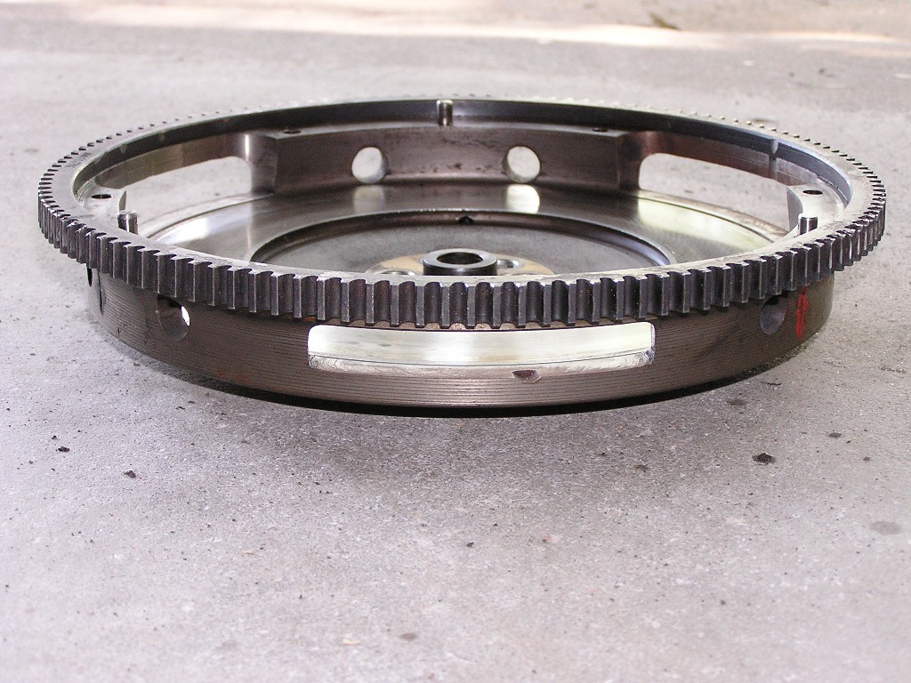
old and new flywheels
of course we don't have the torque of a 2.4
and we use an F first gear
Attached image(s)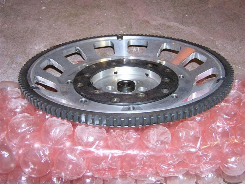
Posted by: sixnotfour Jul 15 2013, 10:48 PM
oh Brant that aluminum one is real vintage alright 
Posted by: brant Jul 15 2013, 10:49 PM
its Frank Becks toss off.....
he went to a 4.5 diameter clutch to save weight
Posted by: pcar916 Jul 16 2013, 03:48 PM
I've had a 6.75lb Patrick Motorsports aluminum flywheel and a push-type clutch on this 993 engine since 1999. No problems. Clutch/pressure plate/flywheel assembly weighs in at about 18#.
Good luck
Posted by: biosurfer1 Jul 16 2013, 04:08 PM
Too light? I think you just killed a little part of Ury with that comment
Posted by: get off my lawn Jul 18 2013, 10:39 AM
how light is your flywheel?
I'd say it's somewhere between a medium silver and light gray, about the same color as yours. Not dark at all.
Posted by: ChrisNPDrider Jul 19 2013, 10:20 AM
My daily driver 914 turned cafe racer AX weekend warrior turned semi-daily driver has a lightened flywheel. It's 12 lbs I recall, behind a stock 1.7 TIV. When the engine is cold, it dies more often than it should. When warm, usually no problem. If you rev up in neutral, the drop back down can sometimes cause the engine to die. It just doesn't have that rotating mass to keep it smooth. I am really good at re-starting the engine no matter where/what. I like that my 914 is so sensitive to driver inputs w the light flywheel, turbo tie rods etc etc
Go for it 
Posted by: GeorgeRud Jul 19 2013, 10:29 AM
Figure that the heavy outer starter ring is at the perimeter, I think this should work fine. Just don't put a 'puck' type clutch disc in the car if it's going to be a street driven car!
Posted by: McMark Jul 19 2013, 11:26 AM
Cool. Sounds like this flywheel will be fine. I can always swap it out later if need be.
On to the next subject!
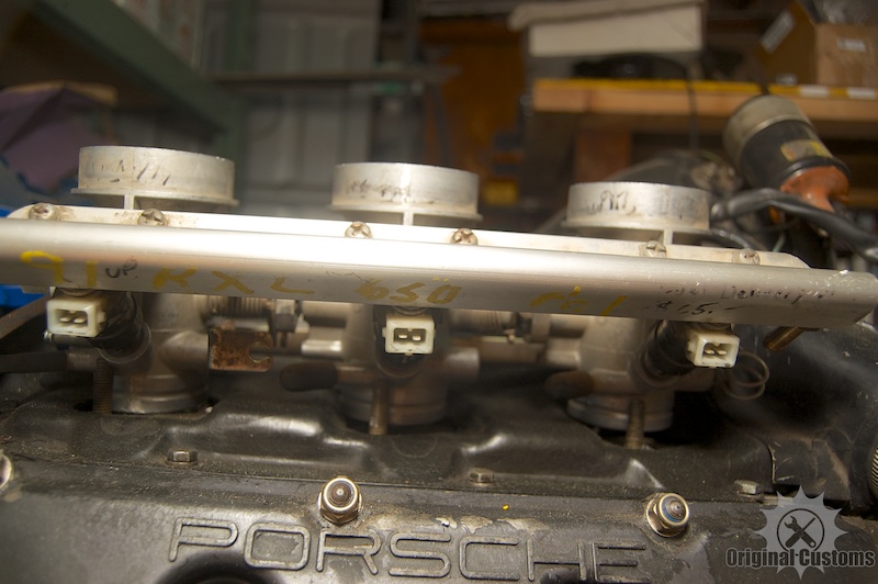
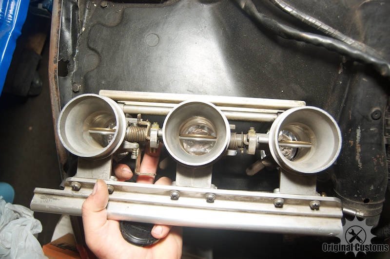
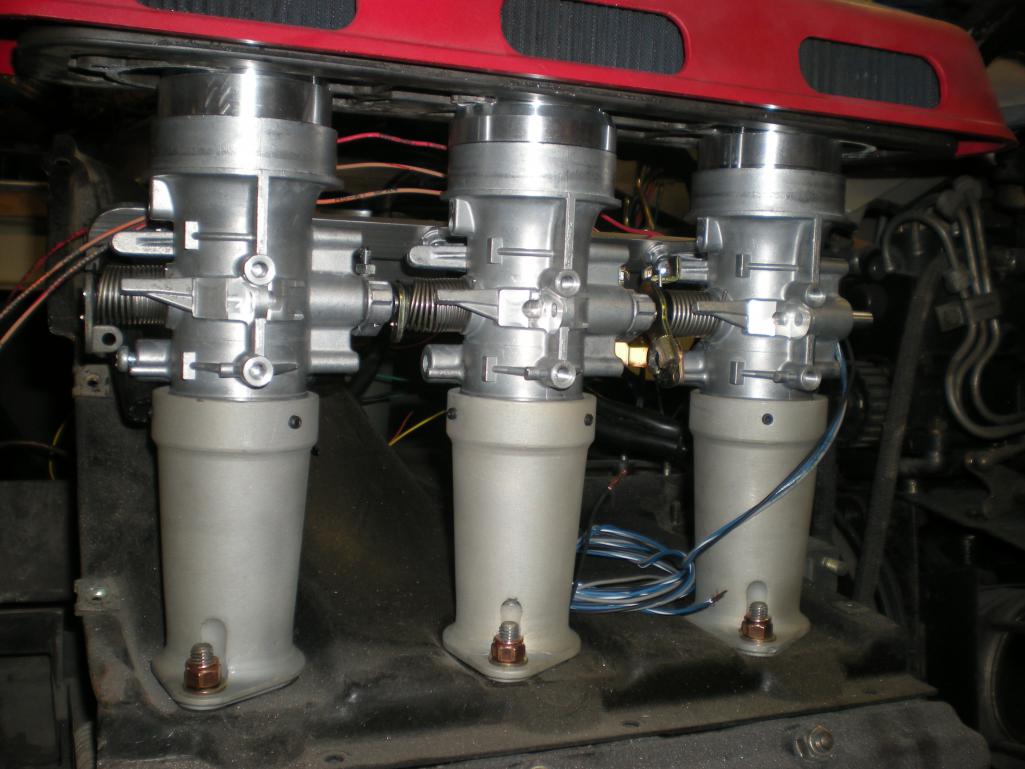
These are the throttle bodies I will be using. They are from a Polaris 650. They line up perfectly with the intake ports, but I'll need to make adapters to make them fit. They're fairly large at 46mm, but I think they'll work okay.
I need to transition from the intake port size (36mm I think) to the TB size (46mm). There are two options I can think of that I like. Have a flange cut from 1/2" aluminum and taper the inside. The other is to have longer transitions, but this would mean CNC milling.
So there's the question: longer smoother transition intake, or short quick transition? 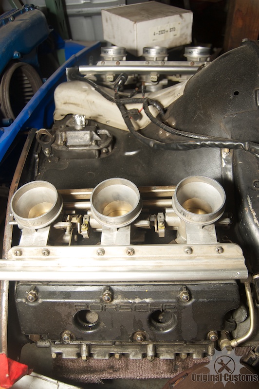
Posted by: JmuRiz Jul 19 2013, 12:04 PM
With a 2.4 I'd go with longer to get a smidge more torque....
Those throttle bodies look really cool, can't wait to see what you do, and if you want to make another set...let me know.
Posted by: BKLA Jul 19 2013, 02:32 PM
Love the polaris TB's! Great Idea!
Posted by: scotty b Jul 19 2013, 03:22 PM
What cams are you using ? 
Posted by: Dave_Darling Jul 19 2013, 03:37 PM
Remember that the factory went to high-butterfly throttles in some of their race motors. I bet that was to allow them nice longer transitions in diameter, plus a longer distance after the injector squirted the fuel into the air stream for it to mix and vaporize.
I think you should go for the longer intakes. Can you do the machining yourself, or do you have to farm it out?
--DD
Posted by: kg6dxn Jul 19 2013, 06:23 PM
Longer runners will give you better low end torque. Shorter will move the torque curve higher typically.
What is your goal?
Make sliding adjustable runners with O rings. Then tie a linear actuator to them. Control the actuator with an rpm counter to raise and lower as you drive... EASY! 
Mazda did this on racing engines. a NA 4 rotor did over 750hp. The RX-8 has multiple runners that are rpm/load controlled valves to lengthen and shorten the runners.
Posted by: McMark Jul 19 2013, 06:41 PM
Street engine. I like torque.
Posted by: r_towle Jul 19 2013, 08:37 PM
2 flanges cut.
Two pieces of tubing, cut stretched, welded.
Then tig it all together...
As I was thinking about it, you should be able to hammer a tube to get 10 mm out of one end....
I would think a bit of time on the sharp end of an anvil, with some patience, you could make the tube cone shaped..
Just a thought.
Also, aren't the Ida carbs 46 mm?
What kind of parts can you find using that stuff?
Might want to contact Eurometrics, he specializes in the old carbs...
Posted by: JmuRiz Jul 19 2013, 09:15 PM
Carbs for up to 3.0 are typically 40, but this size will work well with EFI, as the computer can better control the fuel delivery. Seems like a good size, from the little bit I've heard.
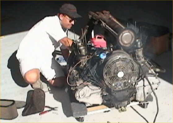
Posted by: McMark Jul 26 2013, 08:08 PM
Okay, time for another thought/question. The engine is a bit unknown on the inside. Here's the story that came with it.
E cams
1969 Factory "S" heads
a. Port size 36X35 38mm intake
b. Valve size 45X39
1972 engine case
Engine right side below shroud: *6123464
Question is, should I pull the heads off and check what all I've got? Maybe a valve cleanup job?
Posted by: kg6dxn Jul 26 2013, 09:40 PM
Open it! You know you want to. DO IT!!!
Posted by: Mark Henry Jul 26 2013, 09:51 PM

Okay, time for another thought/question. The engine is a bit unknown on the inside. Here's the story that came with it.
E cams
1969 Factory "S" heads
a. Port size 36X35 38mm intake
b. Valve size 45X39
1972 engine case
Engine right side below shroud: *6123464
Question is, should I pull the heads off and check what all I've got? Maybe a valve cleanup job?
Slippery slope.

Posted by: rick 918-S Jul 26 2013, 10:02 PM
Do a leak down first and make sure you "need to"
Posted by: McMark Jul 27 2013, 02:58 AM
It's more about knowing what heads, cams, pistons and compression ratios.
I have been dying to build another six engine. This isn't exactly a build and I don't have the funds to actually change anything so it can't get too crazy, other than possibly adding spacers to lower compression so I can run dual turbos. (yeah, I have the disease)
Posted by: Gary Jul 27 2013, 04:00 AM
Hey Mark - is this the motor I dropped off? If so, I have details on the build.
Posted by: Eric_Shea Jul 27 2013, 10:14 AM
What does this mean?
a. Port size 36X35 38mm intake
36 intake
35 exhaust
38?
Only two ports per head.
Posted by: sixnotfour Jul 27 2013, 10:33 AM
that configuration only has about 8-1 compression.
sell the 69 S heads and buy find some 2.2-2.4 heads.
T and E heads have the same port size. You will get easy to find valves, 40/46 and get back the .5 compression
they are easy to port to 36mm intake, Well depending on how you do it..
Or just run it, since you want to TURBO
Posted by: Dr Evil Jul 27 2013, 11:22 AM
![popcorn[1].gif](style_emoticons/default/popcorn[1].gif)
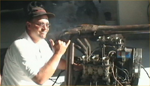
Posted by: Trekkor Jul 27 2013, 10:16 PM
Bolt on a set of carbs and run it on the test stand.
KT
Posted by: McMark Aug 5 2013, 11:30 PM
The $2500 carbs I don't have? Life is so simple when you're spending someone else's money.  Plus, what do I learn from bolting on carbs. I'm not building a car. I'm building an education.
I've been wanting to start familiarizing myself with AutoCAD and this seemed like a good project for this since the intake adapters I'll need are relatively simple.
I started with an intake gasket and scanned it. Then cheated and drew the outline in Illustrator since I can bang that out in about 2 minutes. Then imported that into AutoCAD and did the extrusion. It's pretty boring at this point. Gotta measure my actual intake port size, the OD of the throttle bodies, and decide on the height of the adapters I need/want. Then I'll start working on the actual tapered tube portion.
Attached image(s)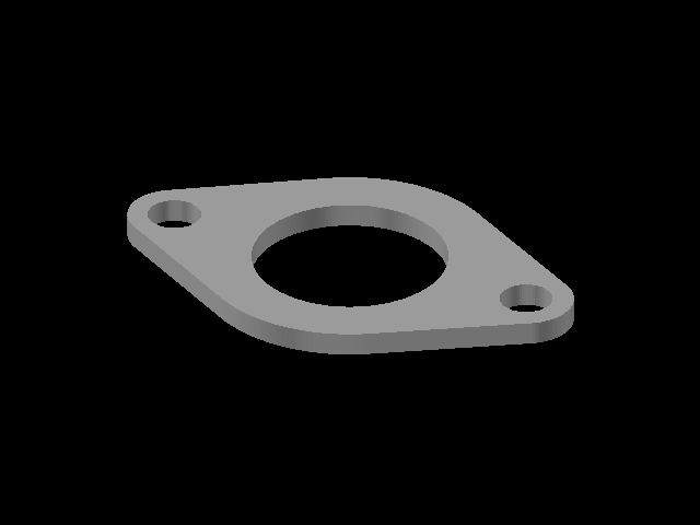
Posted by: McMark Aug 9 2013, 01:15 AM
Finished the intake drawing (I think). Now I need to find someone who can print a prototype for me.
Attached image(s)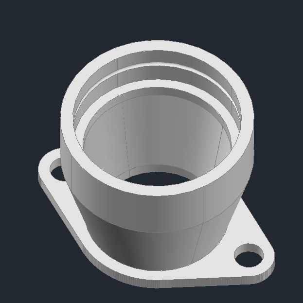
Posted by: jimkelly Aug 9 2013, 06:48 AM
will those Polaris fuel injectors provide enough fuel?
Posted by: McMark Aug 9 2013, 10:39 AM
The injectors are pretty standard. So I was already planning on swapping them, I just haven't done any research into finding what I want to use. Something high impedance is certain, but I also need to find out what flow rate I need.
Posted by: polo classic Aug 9 2013, 12:33 PM
Do you know what distance is from the throttle body to the valve on the OEM Porsche high butterflies throttle bodies?
From looking at the Rothsport versions, it looks like the manifolds are around twice the height of the throttle bodies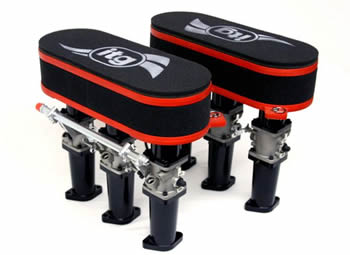
Posted by: McMark Aug 9 2013, 01:59 PM
Not sure. I drew up 'shorties' because once I looked at the room in the 914 engine bay, there's only about 11" overall of space from the cylinder head mounting to the top of the engine bay. The TBs are about 4.5" and short, individual K&N filters are about 2", which leaves 4.5" of room for the adapters. And that's if I use all the available space. So I decided to just design the shorts ones and get a prototype made so I can hold it in my hand and see how it looks.
Posted by: Trekkor Aug 9 2013, 03:25 PM
The $2500 carbs I don't have?
Life is so simple when you're spending someone else's money. Plus, what do I learn from bolting on carbs. I was under the impression that this was an unknown condition motor that you were trying to determine whether or not it needed rebuilding.
I have a set of carbs/manifolds you could borrow for testing off my 2.6 race motor.
I still have that 6 into 1 tee pee off road exhaust for full effect...
KT
Posted by: McMark Aug 9 2013, 04:29 PM
Ahhh, thats makes more sense.  I expect it runs. I'm just planning on pulling it apart to know for sure what's inside and what the compression is, etc
Posted by: McMark Aug 9 2013, 07:28 PM
Prototype printing underway (not by me). 
Attached thumbnail(s)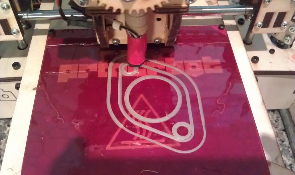
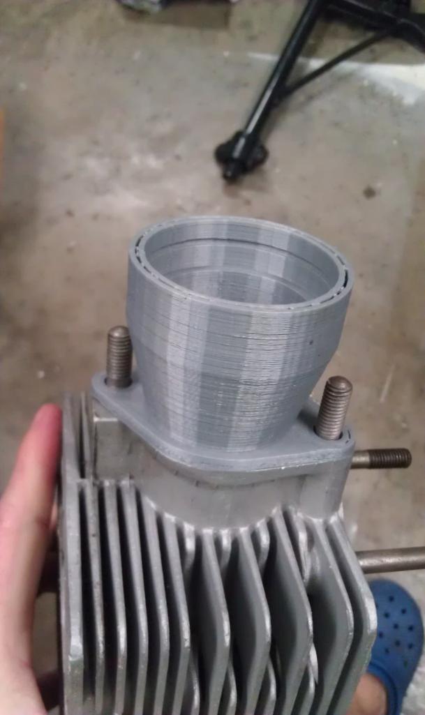
Posted by: McMark Aug 9 2013, 11:09 PM
All done an ready to ship to me.
Attached thumbnail(s)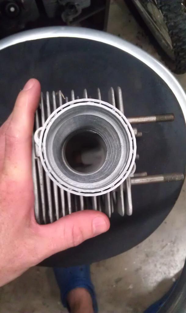
Posted by: euro911 Aug 10 2013, 01:09 AM
Cool.
What is the material, Mark?
Posted by: jimkelly Aug 10 2013, 04:17 AM
why the groove seen from top? is it a two piece part glued together?
so the printer does not cut material away from a block of material - instead - it builds material up and up and up till a part is done ?
Posted by: jpnovak Aug 10 2013, 06:18 AM
I hope Mark doesn't mind my response. I am printing the prototypes for him.
I am many have seen/heard about 3D printing. It is a pretty cool process.
The process starts with a 3D CAD file. There are many ways to get one of these but the process involves modeling in a CAD program. The CAD file is then transformed to a "surface" file that is a map of the external surfaces of the part. The printer software then slices this into invidividual layers. These are cross-sections cut to the plane of the base substrate. Its kinda like a stack of Pringles Chips.
Once the software knows what each layer looks at it starts the printing process. The printer is a hot filament extruder. There is a feed stock roll of plastic wire filament. There is a pinch roller and toothed gear that forces the plastic through the hot extruder tip (230 deg C). The tip is then numerically controlled via a standard coordinate system. Its like putting a tube of toothpaste on a XYZ positioning system.
The part prints the inner and outer perimeter first and then fills in the void space with a criss-cross pattern. The density of the fill is adjustable. The grove in the top is a software glitch where two perimeter lines close together do not get adequate fill due to the narrow space between them.
If you look at the part you can see the individual layers that are stacked. This is the concentric surface finish. There are ways to smooth this easily. The pictures just show the raw part off the printer to check for dimensional fit.
I printed these parts in ABS plastic. This does not print as smooth as the other common filament , PLA.
The prototyping process is VERY fast with one of these printers even if the print process is slow. This part took about 3 hours of print time. Material cost is just a few $. The process creates an accurate part for mock up and test fit. It is easy to modify parts without spending a lot of machine time and cost at an outside vendor. Compared to prototyping in a machine shop there is no cost comparison. Cheaper. Faster. Simpler.
PM me if anyone has an interest in having parts made. I have very reasonable rates.
I hope Mark likes the part. I plan to ship it out today.
Posted by: Krieger Aug 10 2013, 09:27 AM
Very cool to see the cutting edge printing edge applied to our cars.
Posted by: McMark Aug 10 2013, 09:39 AM
Thanks for chiming in Jamie. I didn't know if you wanted to be identified.
Apparently this ABS plastic is suitable for actually running on the car, but once I have a design that works, I'll be researching aluminum CNC production.
Posted by: polo classic Aug 22 2013, 02:43 PM
Did you ever consider using Boxster/997/996 parts, seeing the port spacing is similar, although the water stuff have oval ports
http://forums.pelicanparts.com/porsche-911-technical-forum/732142-intake-port-spacing.html
http://www.ebay.com/itm/OBX-ITB-INDIVIDUAL-THROTTLE-BODY-48MM-Porsche-Watercooled-911-boxster-/151104914392?pt=Motors_Car_Truck_Parts_Accessories&hash=item232e8e03d8&vxp=mtr
(I know some, if not all OBX parts suck)
Posted by: McMark Aug 22 2013, 05:23 PM
Cool! Hadn't seen that. I'd like to try that sometime. 
Posted by: tscrihfield Aug 22 2013, 05:37 PM
This looks very cool! What are you going to have them cast/molded out of?
What is your plan for engine management? 
Thomas
Posted by: McMark Aug 22 2013, 06:24 PM
If the prototype adapters work ill send the CAD files out to mill from billet aluminum.
I'll be using a MegaSquirt system I picked up. Still have to modify it for COP.
Posted by: jcd914 Aug 22 2013, 08:02 PM
If the prototype adapters work ill send the CAD files out to mill from billet aluminum.
I'll be using a MegaSquirt system I picked up. Still have to modify it for COP.
When you get to the "ill send the CAD files out to mill from billet aluminum" part of this project my brother works for a machining company, programming, running and supervising their mills. They have at least 2 monster 5 axis mills. I don't know if he can save you money but it is worth asking.
Jim
Posted by: edwin Aug 23 2013, 07:12 AM
This part has "home cast aluminium" written all over it
You know you want to try it Mark
Posted by: rhodyguy Aug 23 2013, 07:24 AM
home cast? as in a garage?
Posted by: McMark Aug 23 2013, 08:01 AM
Actually I do. Casting has been on my todo list for a long time now.
Posted by: jbyron Aug 23 2013, 09:38 AM
Looking at the pic, I'm concerned whether or not there's clearance to thread a nut onto the stud.
Posted by: GeorgeRud Aug 23 2013, 06:20 PM
Yeah, it does look like you might have to lift it, start the nuts, then tighten it down. Then again, they do make shorter studs!!
Posted by: McMark Aug 23 2013, 06:29 PM
George is thinking along the same lines as me.
The walls on the adapter are pretty thick too, I could probably add some clearance.
Posted by: McMark Oct 26 2013, 10:59 PM
Quick update...
Intake manifolds are at the machine shop getting carved from aluminum. 
Posted by: tscrihfield Oct 26 2013, 11:28 PM
Quick update...
Intake manifolds are at the machine shop getting carved from aluminum.
Awesome! Can't wait to see them!
Posted by: veekry9 Oct 27 2013, 03:49 PM
This is Great.
Thanks for showing the World the latest in NewFangled Tech.
An Idea to Part in hours and not days,the response time of
CadCam system Integration in Manufacturing Systems.
You too can have your very own Protype shop in your garage.
Just like the Mechanix Illustrated BluePrints of the 60's.
Time to fire up your
[4valve head prototype investment casting pattern]
[transaxle housing]
....anything you can dream up.
the Future is Here Now.
Try the Rhino4 or 5 Cad.
Synergy by Weber is a cost effective Cam.
EMC2 is an OpenSource Machine Control System.
There is a lot of competition in the machining industry for large
systems.50K is likely beyond the pricepoint for the home user.
You have to look around and test,then make the decision that suits you
best for the most you wish to spend.There is a fellow here doing a custom
oil scavenge pan for his V8 conversion,inhouse or subcontracted?
It is possible to do it inexpensively,however,the labour intensity rises
accordingly.
A good example of the technology available today.
https://www.youtube.com/watch?v=r7V57_7H9zw
A 20yr old Hardinge retrofit.
https://www.youtube.com/watch?v=35tHYaDUmZQ
A Large 5axis from the 60's retrofit
If they can do it,so can we.
Posted by: veekry9 Oct 27 2013, 04:15 PM
This part has "home cast aluminium" written all over it
You know you want to try it Mark
https://www.youtube.com/user/myfordboy/videos
A Sandcasting Tech Revival,or How to make your own Porsche
Parts.
https://www.youtube.com/watch?v=M95bhPrDwA0
If he can do it,what's stopping you (us)?
Labour Intensity of a kind our ancestors knew in the steam era.
Posted by: sixnotfour Nov 8 2013, 02:03 PM
These are mine. A little different from Mark's. Taller
Attached thumbnail(s)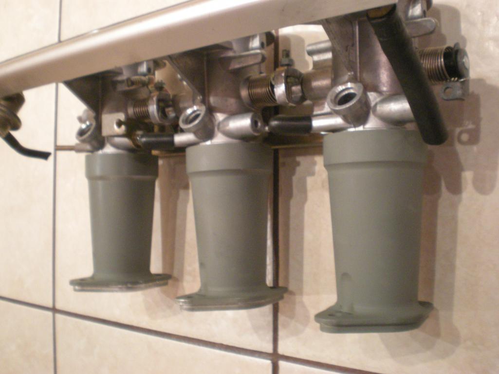
Posted by: McMark Nov 8 2013, 04:14 PM
Wow, looks great. Perfect timing, cause I just got pics from the machine shop. Mine are done in machining. Next, a quick hard-coat anodizing.
Attached thumbnail(s)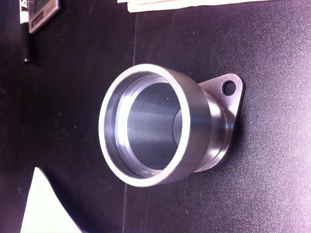
Posted by: jimkelly Nov 8 2013, 04:15 PM
absolutely beautiful 
Posted by: sixnotfour Nov 8 2013, 04:59 PM
sweet !! How are you adjusting the 2mm spacing diff. ??
Posted by: McMark Nov 8 2013, 06:08 PM
TBD. I should actually have them in my hands in a couple weeks. Then I can start on the linkage.
Posted by: 914Timo Nov 9 2013, 12:16 PM
These are mine. A little different from Mark's. Taller
Wow !! Those are cool. Sorry McMark, I am not trieing to hijack this, but I would like to know whats the story behind Mr Sixnotfour´s ?? Are they 3D pinted, cast or what ?? Whitch TBs those are??
Posted by: sixnotfour Nov 9 2013, 04:06 PM
mine are machined aluminum, with the flanges welded on, because of the free material being small in diameter.. I just like green.. Mark can tell the injection story, I just happen to be doing the same, but different.
Posted by: jpnovak Nov 9 2013, 08:31 PM
Those look great!
Posted by: rick 918-S Nov 9 2013, 10:59 PM
Nice projects
Posted by: sixnotfour Nov 17 2013, 03:52 PM
Attached thumbnail(s)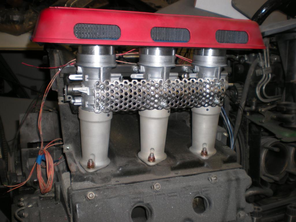
Posted by: Dave_Darling Nov 17 2013, 10:48 PM
It looks cool, but what's the perforated metal for?
--DD
Posted by: McMark Nov 17 2013, 11:07 PM
Those are Jeffs, but it's a mount. It ties the three TBs together. The spacing on the Polaris TBs is just a little off. So the mount that comes on them won't work.
Posted by: ConeDodger Nov 18 2013, 10:04 AM
Those are Jeffs, but it's a mount. It ties the three TBs together. The spacing on the Polaris TBs is just a little off. So the mount that comes on them won't work.
Mark, It looks like the TB's are attached to the printed intakes with set screws. I'm still thinking of using these with my Datsun L28 motor. I think these could be tied together with a heat shield under the TB's and over the header?
Posted by: McMark Nov 18 2013, 12:13 PM
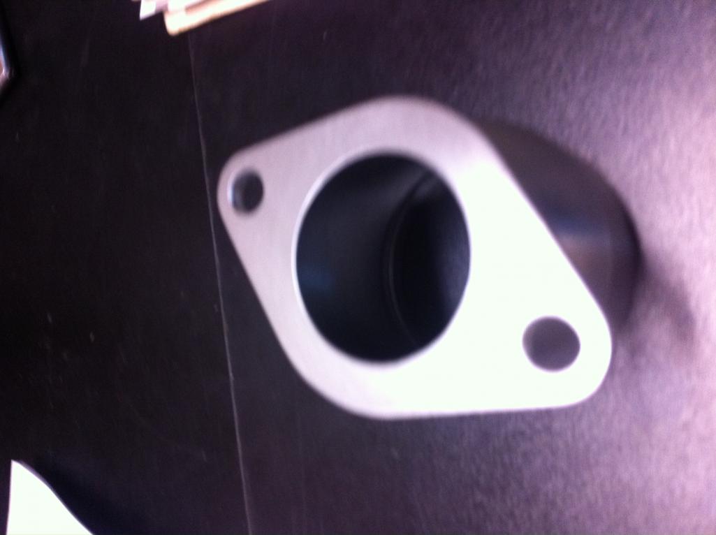
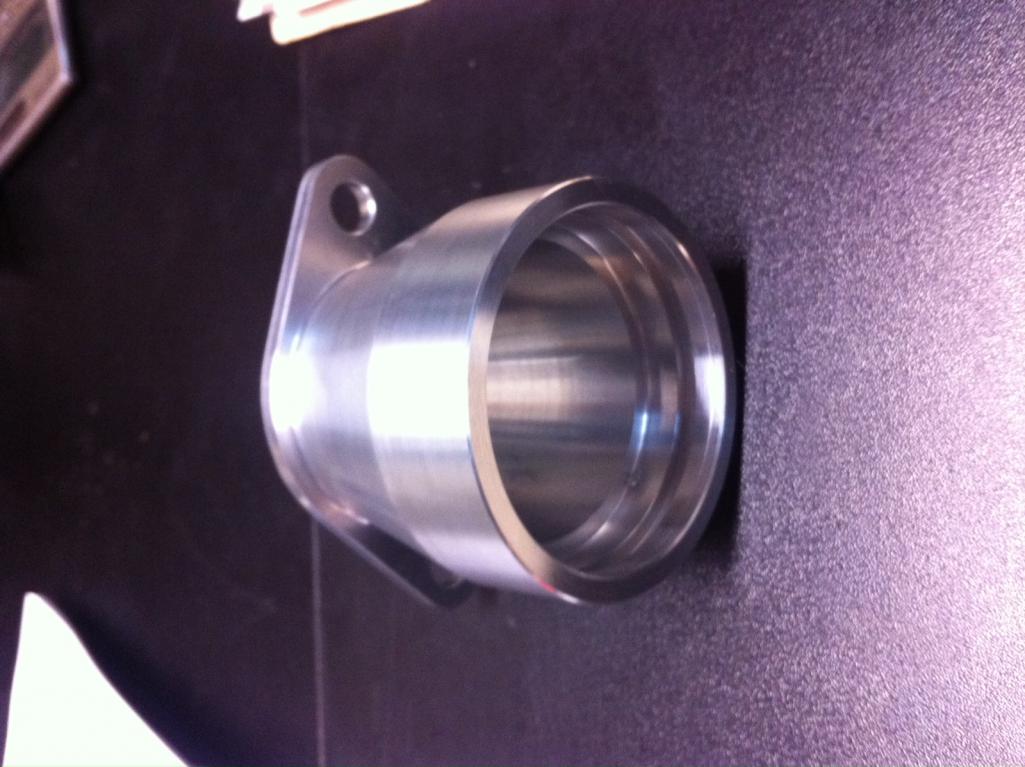
Here's my adapters. Got a sample piece in bare aluminum. The other 13 pieces are out for anodizing.
Attached image(s)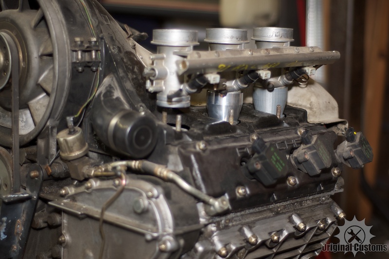
Posted by: Series9 Nov 18 2013, 12:21 PM
I REALLY like it!
Posted by: JmuRiz Nov 18 2013, 12:31 PM
Very cool stuff, definitely keeping my eye on this.
Posted by: sixnotfour Nov 18 2013, 02:43 PM
Those are Jeffs, but it's a mount. It ties the three TBs together. The spacing on the Polaris TBs is just a little off. So the mount that comes on them won't work.
Mark, It looks like the TB's are attached to the printed intakes with set screws. I'm still thinking of using these with my Datsun L28 motor. I think these could be tied together with a heat shield under the TB's and over the header?
They are aluminum, and will be sealed in with 890 sealant from expired product from work. set screws are just extra.
Mark mine are still 116mm the two outer intakes stacks are angled in. The stainless perf. was leftover, just tried something different. I also removed the coolant passage
bosses.
Attached thumbnail(s)
Powered by Invision Power Board (http://www.invisionboard.com)
© Invision Power Services (http://www.invisionpower.com)