Printable Version of Topic
Click here to view this topic in its original format
914World.com _ 914World Garage _ Tach/Turn signal conversion doesn't work
Posted by: sfrenck Jul 28 2013, 12:01 PM
Used this information to install my 73 Tach into my 74 car:
You would add two wires from the emergency flasher switch to the bulbs you will use (green/black and white/ black). These are the same wires and colors leading out to the turn signal bulbs at the four corners of the car.
You will modify the existing blue/white wire to extend to the other side of BOTH bulbs. The blue/white wire terminates at the flasher relay itself.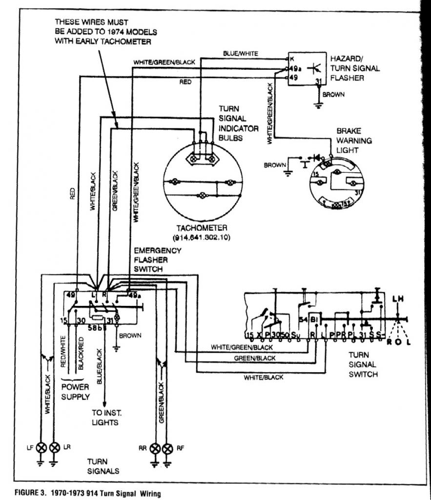
Weird thing is when all the wires are connected to the hazard switch, neither indicator works for flasher or turn signal. If I unplug the L or R from the hazard switch, both turn signal indicators work as they are supposed to and one of them lights up with the hazard (whichever one I didn't unplug)? I've already switched out the hazard switch.

Question change: the turn signal indicators work with the turn switch when all is wired per the diagram, but they don't blink with the hazard switch (light on the hazard switch does blink). Is this how it is supposed to work?
Newer Update: All works if I detach the blue wire w/ white stripe from the turn indicator bulbs and instead install a ground to them. Guess I'm going with this solution rather than the diagram above indicating I need the two blue/white stripe (or, as indicated below, take the blue/white wire off of the flasher at terminal K and connect the wire to ground).
Posted by: 904svo Jul 28 2013, 01:43 PM
Reverse the left and right leads to the turn singal bulbs and try that.
Posted by: Spoke Jul 28 2013, 01:55 PM

If I unplug the L or R from the hazard switch, both turn signal indicators work as they are supposed to and one of them lights up with the hazard (whichever one I didn't unplug)? I've already switched out the hazard switch.
You Wrote:
"If I unplug the L or R from the hazard switch, both turn signal indicators work"
Do you mean if you unplug either wire from the bulbs to the hazard switch, they both work?
If so, you have a wiring error. Looking at the diagram you provided, if either wire from the bulbs to the switch are unplugged, then current cannot flow through that bulb and that bulb cannot light up.
Posted by: sfrenck Jul 28 2013, 02:36 PM
If I unplug the L or R from the hazard switch, both turn signal indicators work as they are supposed to and one of them lights up with the hazard (whichever one I didn't unplug)? I've already switched out the hazard switch.
You Wrote:
"If I unplug the L or R from the hazard switch, both turn signal indicators work"
Do you mean if you unplug either wire from the bulbs to the hazard switch, they both work?
If so, you have a wiring error. Looking at the diagram you provided, if either wire from the bulbs to the switch are unplugged, then current cannot flow through that bulb and that bulb cannot light up.
Hmm... after further playing it seems that the hazard switch making the indicators blink is the issue. The turn signals work (power comes from the turn signal, not the hazard switch) in all cases.
Posted by: sfrenck Jul 29 2013, 04:58 PM
Bump for question change in initial post.
Posted by: 904svo Jul 29 2013, 05:56 PM
Look at the drawing, blue/white supply pulsing +12 to both turn signal lamps.
Then the return ground to the turn signal bulbs go to the opposite light, ie left
gets its ground from right turn bulb and right from the left turn bulb.
Hope this helps.
Posted by: kg6dxn Jul 29 2013, 10:07 PM
You could take the Blue/White wire off the relay (Terminal K)and ground it. Just the wire, not terminal K.
Make sure you have 2 wire lamp sockets and the terminals are not grounded. The sockets should only be grounded if they are single wire. In which case, just remove the wire from terminal K.
Posted by: sfrenck Aug 4 2013, 11:11 AM
You could take the Blue/White wire off the relay (Terminal K)and ground it. Just the wire, not terminal K.
Make sure you have 2 wire lamp sockets and the terminals are not grounded. The sockets should only be grounded if they are single wire. In which case, just remove the wire from terminal K.
This method works.
Posted by: kg6dxn Aug 4 2013, 12:28 PM
You could take the Blue/White wire off the relay (Terminal K)and ground it. Just the wire, not terminal K.
Make sure you have 2 wire lamp sockets and the terminals are not grounded. The sockets should only be grounded if they are single wire. In which case, just remove the wire from terminal K.
This method works.
There is no way the schematic you posted could work without adding diodes into the system to prevent current back feeding. Not sure where you found it but it is drawn wrong.
Posted by: Spoke Aug 4 2013, 04:43 PM
Newer Update: All works if I detach the blue wire w/ white stripe from the turn indicator bulbs and instead install a ground to them. Guess I'm going with this solution rather than the diagram above indicating I need the two blue/white stripe (or, as indicated below, take the blue/white wire off of the flasher at terminal K and connect the wire to ground).
I wired my 74 with early tach in the same way. Essentially you are just paralleling the dash indicators with the outside turnsignal bulbs.
Posted by: Dave_Darling Aug 4 2013, 07:30 PM
The font and style make the diagram look like it came out of an issue of Panorama. Not one I'm familiar with, though.
--DD
Posted by: sfrenck Aug 5 2013, 05:40 AM
You could take the Blue/White wire off the relay (Terminal K)and ground it. Just the wire, not terminal K.
Make sure you have 2 wire lamp sockets and the terminals are not grounded. The sockets should only be grounded if they are single wire. In which case, just remove the wire from terminal K.
This method works.
There is no way the schematic you posted could work without adding diodes into the system to prevent current back feeding. Not sure where you found it but it is drawn wrong.
Got it from this discussion - http://www.914world.com/bbs2/index.php?showtopic=47236&hl=directional Note: thread indicates the diagram is from "UpFixin vol IX on Pages 171 and 172"
Powered by Invision Power Board (http://www.invisionboard.com)
© Invision Power Services (http://www.invisionpower.com)