Printable Version of Topic
Click here to view this topic in its original format
914World.com _ 914World Garage _ Fuel Maps from my Megasquirt
Posted by: DNHunt Dec 7 2004, 10:10 PM
Here's a fuel map i preloaded for my new engine as a starting point. Certainly it's too rich but, it should be safe.
Attached image(s)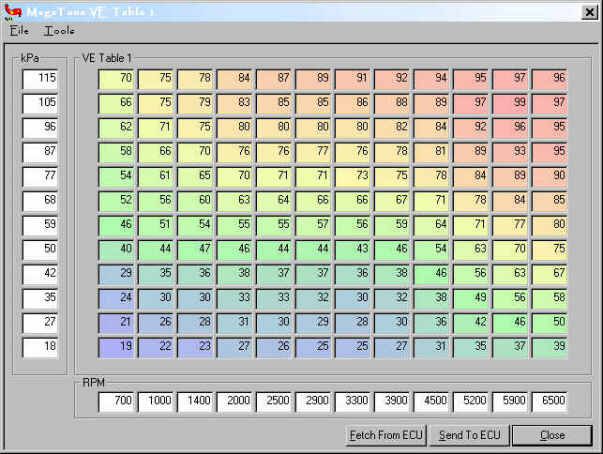
Posted by: DNHunt Dec 7 2004, 10:11 PM
Here's a cool graph of the same thing from the tuning screen
Attached image(s)
Posted by: DNHunt Dec 7 2004, 10:15 PM
Here's the ignition table
Attached image(s)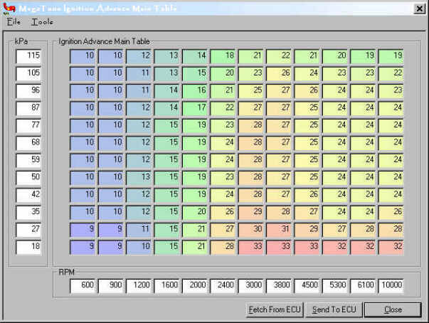
Posted by: DNHunt Dec 7 2004, 10:16 PM
And the spark graph
Dave
Attached image(s)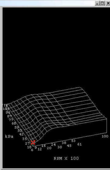
Posted by: Dr Evil Dec 7 2004, 10:42 PM
Your just cool, Dave. I'll be looking you up for graph advise when I build my DIS for the 2.7.
Posted by: drgchapman Dec 7 2004, 10:46 PM
Dave, did you use some base numbers, then allow for your particular engine set up? So as I understand the graphs, or misunderstand, as RPM increases, fuel output increases, measured as partial pressure (kPa), spark advance increases as well up to 32 degreees BTC. I assume that this is related to the torque curve and horsepower curve using some algorithm. Is the fuel delivered same as l-jet, pulse duration variable?
The graphs look really cool. When do you fire her up?
Gary
Posted by: a9146luvr Dec 7 2004, 11:59 PM
Why do i feel i should copy those to my desk top? it'll be interesting how close you are. thanx.
Posted by: chunger Dec 8 2004, 01:32 AM
Is it possible to use this resolution on an earlier MS hardware? Do I need to re-program the chip itself or can it be done w/ re-loading things into memory.
-'Chung
Posted by: crash914 Dec 8 2004, 06:58 AM
Dave, do you really get a 115 Kpa?
I re-scaled my table to go from 0 to about 60 Kpa and RPM up to around 7000...
Just trying to get more resolution to the steps...
Yours looks cool though...are you using the Hi-res code? I don't get the pretty colors with my megatune...
can't wait till you post the pictures of the first drive around the block...
later, herb
Posted by: DNHunt Dec 8 2004, 07:21 AM
The graphs look really cool. When do you fire her up?
Gary
Guys
Right now this is just a quess and I expect it to change a lot. It's loosely based on the fuel map that I ran on my 2.0 l but, I had to expand that from an 8 X 8 grid to a 12 X 12 grid that's in the new firmware.
Gary both maps are dependent on RPM and vacuum. Spark is more closely related to RPM so it changes more in that axis but if you look there is vacuum advance and retard. Fuel map should really reflect the torque curve ofthe engine. This plot is pretty optimistic. If you look at around 900 RPMs and 25 kPa you'll see a small valley where it will idle and there is another valley around 3000 RPMs for cruise.
I really don't expect that much vacuum but I had extra bins so I plugged them in and figured I would tune them later.
The original MS started on an 8 X 8 fuel map from a 350 Chebbie so this should be closer than that.
Dave
Posted by: pbanders Dec 8 2004, 09:23 AM
I would think that if the motor is stock, or nearly so, a good starting point would be to replicate the fuel map from stock by using the injection duration vs. speed mapping of D-Jetronic. See the chart near the bottom of this page: http://members.rennlist.com/pbanders/djetfund.htm
The fuel units obviously need scaling and/or transformation to your mapping. The thing you want to replicate is the curve. From what I saw of your curve, unless I'm misinterpreting it, you're not compensating for the decline in VE above 5000 rpm or so.
The ignition mapping starting point can be derived from the data in the factory workshop manual on the advance curve of the stock D-Jetronic distributor. Mapping the effects of vaccum advance might be tricky, however. Vacuum retard should be fairly easy to map.
Posted by: Jake Raby Dec 8 2004, 09:39 AM
Dave, the fuel does look rich, but safe and easy to start from....
The spark could use some work. I would try using something like this..
1000-12 degrees
1500-15 degrees
2000-21
2500-28
3000-32
3500-32
4000-32
4500-30
5000-28
5500-24
6000-22
This is the curve from an engine that I built and tested with the Kit carlson EFI that had the same cam that you have and similar port work.
At high RPM pulling timing out cleans up the top end since piston speed is higher you don't need much advance to light the fire. The ability to add in more timing down low and pull it away in the top end give the best of both worlds.
Have fun!
Posted by: Mueller Dec 8 2004, 10:23 AM
my 1.8 had 55 kPa at idle, not sure why so far off from your motor and the other guys running MS on the Type IV motors...I tested it an external gauge and got the same reading...
looks like you are making some serious progress Dave

Posted by: nein14-6 Dec 8 2004, 10:53 AM
Dave, Sorry if you have already posted this but what components are you using for ignition this time around?
Thanks,
Rob
Powered by Invision Power Board (http://www.invisionboard.com)
© Invision Power Services (http://www.invisionpower.com)