Printable Version of Topic
Click here to view this topic in its original format
914World.com _ 914World Garage _ Oil system diagram
Posted by: stugray Aug 15 2013, 02:24 PM
I would like to design a dry-sump type of system for my race car.
One thing I have found is that diagrams that show how the stock system works and how to modify it for other parts (coolers, dry sump, "full flow",etc) are hard to find.
So I made this diagram in Visio (CAD-like) so I can move parts around and ask the proper questions.
Does anyone have any suggestions or comments about making the diagram 100% correct before I start trying to modify it?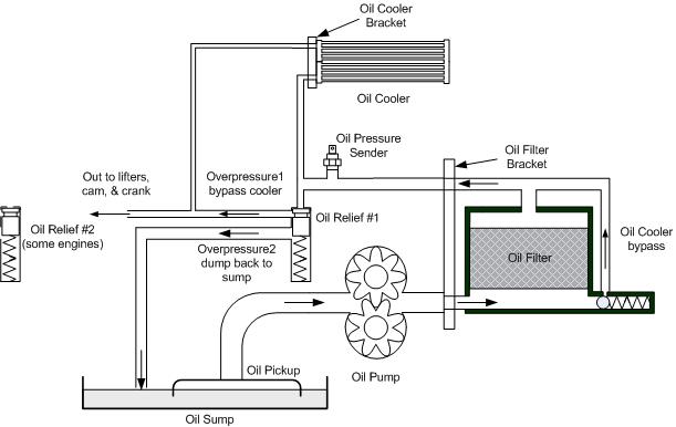
I could provide the original file, but not too many out there have visio.
My next step is to get out a spare case so I can see EXACTLY where these parts go, exactly what any adapter might look like, and identify where all of the galley plugs would be in the diagram.
Stu
Posted by: yeahmag Aug 15 2013, 02:27 PM
I wouldn't try and reinvent the wheel... The CB pump is fine, others are better.
Posted by: stugray Aug 15 2013, 03:21 PM
the CB dual pump was going to be one of my first choices, but I want a detailed diagram before I buy anything dry-sump related.
I just ordered two setrab oil coolers to go up front under the headlight buckets and the fittings to start mounting them.
For now I was going to go with just the coolers and the oil filter sandwich plate, but I want to plumb it smart in case I go to anything more complex.
Stu
Posted by: mrbubblehead Aug 15 2013, 03:40 PM
i posted some diagrams of my system but they were preliminary drawings. not the final. i have over 10k miles on my system. and i am using the cb pump. but my setup is completely different. i eliminated the bypasss and releif valves in the case and welded up the little bleed off holes. now my cooled filtered oil goes straight to the mains. no stock filter. i am useing a remote filter that also bypasses the oil to my sump for those cold mornings.
Posted by: Jeff Bowlsby Aug 15 2013, 03:42 PM
Is this what you need?
Attached thumbnail(s)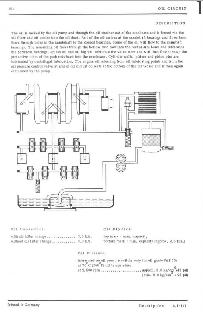
Posted by: stugray Aug 15 2013, 05:27 PM
mrbubblehead, please post links to your diagrams.
Jeff Bowlsby, that is exactly the diagram I used to make mine.
since the original artwork is just that - artwork (bitmap) i decided to make a new diagram using a more modern medium so I can manipulate the pieces.
You might notice one difference: Mine shows that under extreme pressure situations, the first pressure regulator will dump back to the sump.
Notice the stock artwork "hints" at it with the open end on the lower right of the pressure regulator in the stock diagram.
This was based on a recent thread where 'worn' was troubleshooting a stuck regulator piston. (Brant has seen this as well)
I wanted to document what worn found during his rebuild:
http://www.914world.com/bbs2/index.php?showtopic=210207&st=0
That the system will dump back to the sump if the piston is "stuck" too far back in the relief bore.
My next hope is to identify where each of the case galley plugs are in the diagram.
I have seen many discussions about people plugging this or that, blocking off something over here, or installing things like a "Oil Filter, Block-off" or running the oil pumps that dont send any oil through the stock passages.
However during all of those discussions, there have been very few diagrams.
Stu
Posted by: Racer Chris Aug 16 2013, 06:40 AM
I'm developing a kit to delete the stock cooler completely.
I think they are ineffective, especially on modified engines, and the cooling air from the fan would be better used on the cylinders.
The kit will include a take-off for a remote cooler which can go anywhere the user likes.
I also don't much like the sandwich plates or the "full flow" case mods commonly used. They add unnecessary complexity to the assembly.
Posted by: motorvated Aug 16 2013, 06:45 AM
You labeled the oil filter bypass incorrectly.
Posted by: mrbubblehead Aug 16 2013, 03:51 PM
heres my basic plan. i will have to draw up the full system. if you want to see it. http://s722.photobucket.com/user/mrbubblehead_photos/media/type4oilroutingrevised.gif.html
1. remote bypass filter.
2. cooler
3. sump
if you notice, the bypass and relief valves are eliminated. as well as a bunch of very tight 90 degree direction changes that ate machined into the case.
Posted by: stugray Aug 16 2013, 04:26 PM
mrbubblehead,
thank you. your diagrams from the other thread were my inspiration.
I understand that you can close off some ports (with welding) or other ports (with blockoff plates) or use bypass plates, etc.
I want to have diagram(s) that show all the various possibilities.
This is a good start and I can share the cad diagram in more than one format as we move forward.
Stage-1:
External Oil cooler with minimum changes = the oil filter sandwich plate with plumbing to cooler element only. Everyone knows how to do this, you can buy the kit from AA
Stage-2:
Remove stock oil cooler and oil filter bracket and plumb in remote cooler (completed in step 1) and install better remote filter option.
This will give any oil filter option desired plus protect expensive cooler option (from step 1)
Stage-3:
Remote oil filter bracket has built-in pressure relief so that stock relief valve can be removed/bypassed. This must dump back to case (oil galley plugs or 'retired' pressure regulator port?)
Stage-4: Full blown dry-sump with dual oil pump and 6-cyl like oil sump/tank.
I have already committed to dual front oil coolers beneath the headlight buckets. Now I want to plumb it as smart as possible to make transitions from stage-1 to stage-3 as painless as possible.
I will update the diagram this weekend with the correction above and what i learn from navigating through my spare case this weekend
Stu
Posted by: stugray Aug 17 2013, 01:18 AM
Better diagram: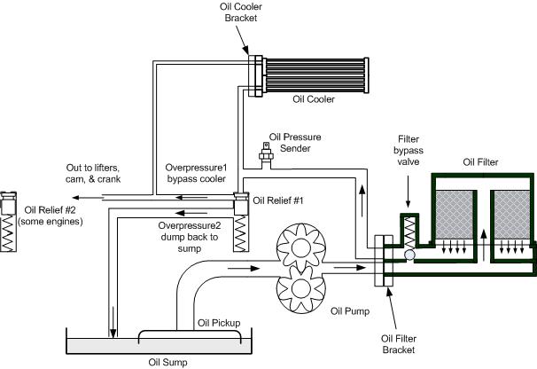
And I have the spare case on the stand so I guess it is due for a galley plug upgrade next ;-)
Its another single relief.
Oh and I verifed that the "dump back to the sump" in the pressure relief valve is just channels cut on opposite sides of the bore.
Once the piston moves down far enough to expose the channels it dumps into the bottom of the relief valve where the spring is and there is just a hole to the sump down there.
Stu
Posted by: worn Aug 17 2013, 10:42 PM

I'm developing a kit to delete the stock cooler completely.
I think they are ineffective, especially on modified engines, and the cooling air from the fan would be better used on the cylinders.
The kit will include a take-off for a remote cooler which can go anywhere the user likes.
I also don't much like the sandwich plates or the "full flow" case mods commonly used. They add unnecessary complexity to the assembly.
Hi Chris,
I want it. Do I have to drop the engine? Also, how is the fan flow rerouted. Thanks for taking this on. You do great stuff.
Posted by: Dave_Darling Aug 17 2013, 11:01 PM
You're not going to remove the cooler from the engine with the engine in the car. Not without doing a whole lot more work than just dropping the motor.
(Yeah, you theoretically could remove the studs that hold the cooler on, but it would not be easy and you'd have to somehow thread them in again through the new part.... Not to mention fitting the bypass for cooling air!)
--DD
Posted by: ClayPerrine Aug 17 2013, 11:14 PM
You're not going to remove the cooler from the engine with the engine in the car. Not without doing a whole lot more work than just dropping the motor.
(Yeah, you theoretically could remove the studs that hold the cooler on, but it would not be easy and you'd have to somehow thread them in again through the new part.... Not to mention fitting the bypass for cooling air!)
--DD
Dave.... It's not hard to remove and replace the cooler when the motor in the car. I did it in the hotel parking lot in Salt Lake City.
Posted by: stugray Aug 18 2013, 12:40 AM
The next stage is remote oil filter bracket with remote pressure regulator.
The CB remote filter bracket isnt 12AN size, so might go towards the Canton components.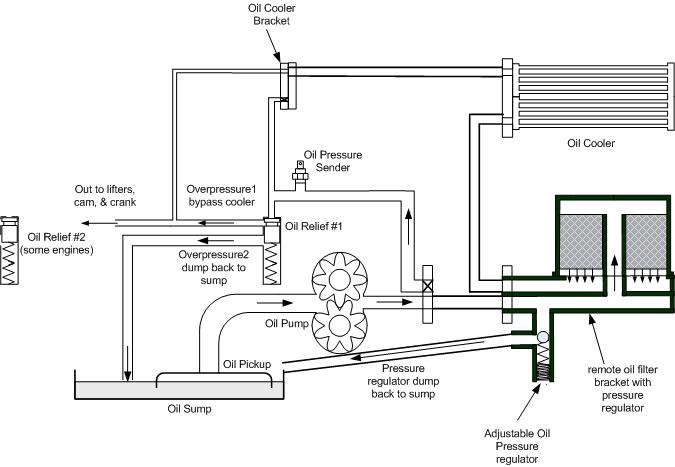
The black "X"s indicate blockoffs, but now it is apparent that some of these applications require non-trivial solutions.
Stu
Posted by: Racer Chris Aug 18 2013, 07:33 AM
Hi Chris,
I want it. Do I have to drop the engine? Also, how is the fan flow rerouted. Thanks for taking this on. You do great stuff.
Removing the cooler really isn't much more difficult than replacing the seals with the engine in the car.
The 3 studs need to be removed anyway, to be replaced with short studs or 20mm hex head screws.
The fitting adapter is much like an old type 1 remote cooler adapter but designed to route the hoses where we need them.
The right side cooling flap will be replaced with a fixed piece which closes off the oil cooler air passage completely.
To my mind this is a far better setup than either a sandwich plate cooler takeoff or a full flow case modification.
The stock filter is retained with no mods, therefore the filter bypass is unaffected, and there is no interference with engine mounts, etc.
A remote thermostat is incorporated in the hose routing, and a choice of rear or front mounted cooler is easily accomodated.
My barebones kit will terminate at the thermostat, leaving the user to select his cooler of choice and supply the appropriate hoses.
I've discovered that even the stock cooler mounted in a less than ideal remote location provides better oil cooling than when mounted on the engine and cooled by shroud blown air.
Posted by: stugray Nov 23 2015, 09:40 PM
So I went ahead and used the car for one season (part of one anyway) with the new coolers in the front.
It worked very well. Almost too good.
Even after a hard 20 minute race I rarely saw much over 220.
This is with the dual front coolers in under the headlight buckets venting through the fenderwells.
Hole through front with tunnel and holes through fender: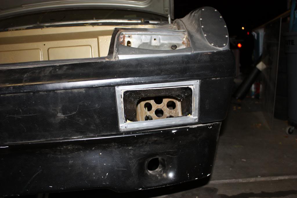
Finished vents (complete with bugs and road clag):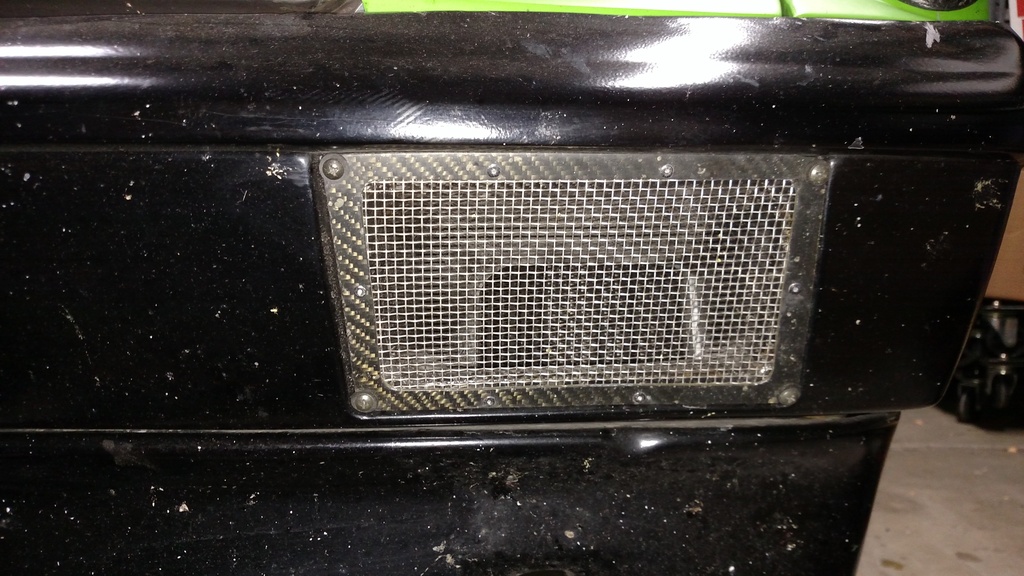
Whole front end with view of cooler line routing: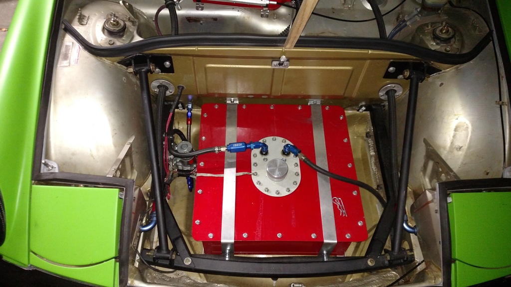
Driver's side cooler hiding: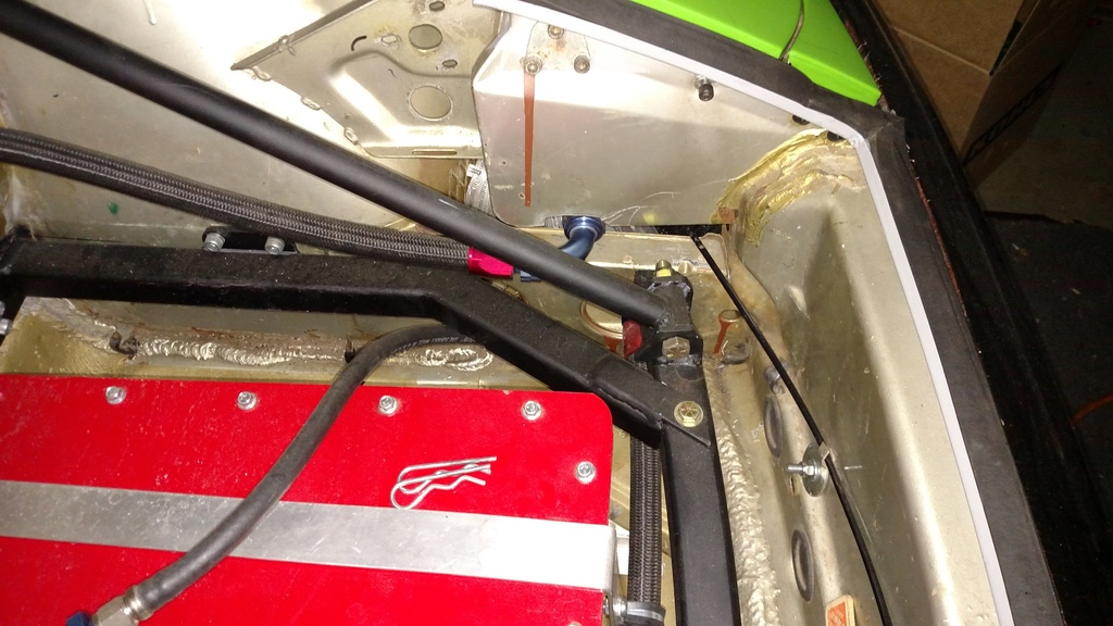
I have this currently just plumbed into the system with 12AN directly with a sandwich adapter at the oil filter.
Next will be to include a thermostat and remove the sandwich adapter.
And add an accusump oil accumulator.
I chose to go with Tangerine Racing's oil cooler block off plate.
It has 3/8 female pipe threads.
I converted those to 10AN between the engine and the thermostat and to the accusump.
The output side of the thermostat has 12AN adapters to go to the coolers.
Here's the bracket I made up to hold the (massive) thermostat with the associated plumbing.
I chose to include a one-way check valve between the engine high pressure input line and the thermostat.
Then the accusump feeds straight into the cooler block off plate.
So if I blow an oil cooler (most likely failure scenario) the accusump wont just dump all the oil out on the ground.
The check valve will force the reserve into the engine.
(It sure is nice to have a spare engine and stand laying around :-)
Here's a view as if you were laying under the car: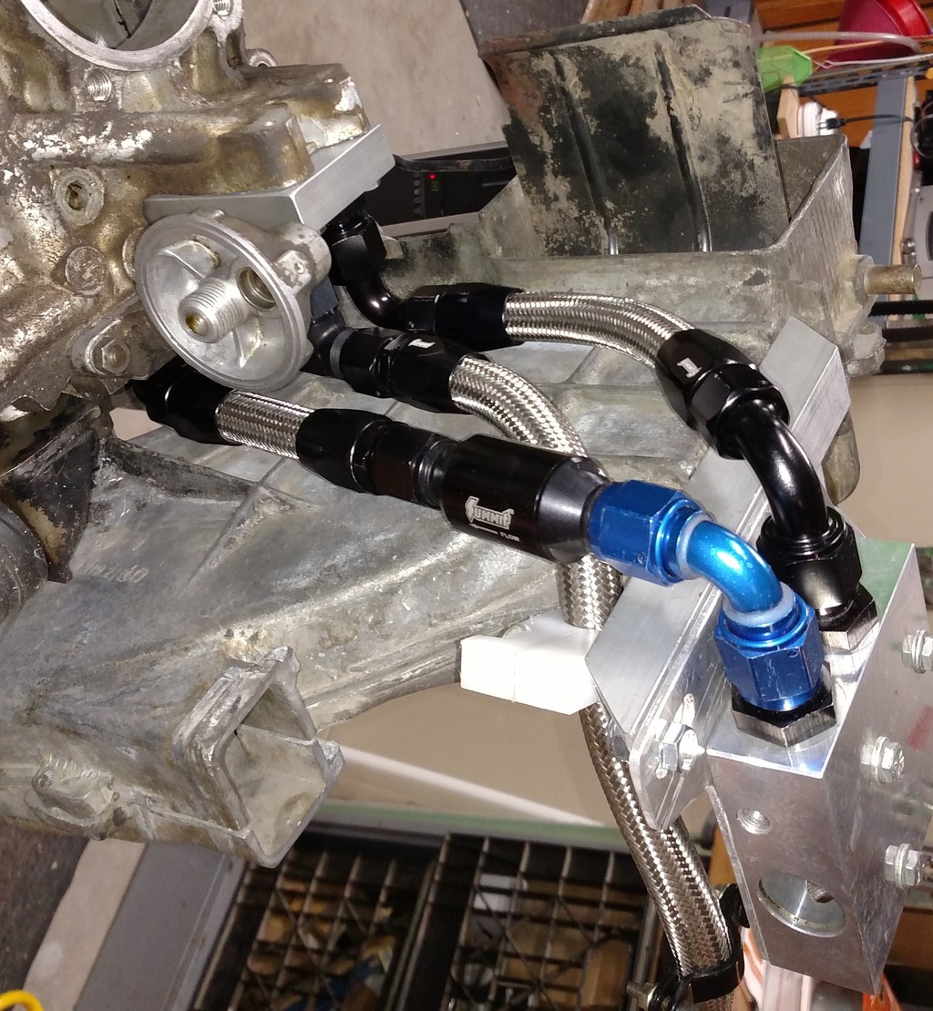
near the top of the pic is the line out from the engine to the thermostat.
middle line is routed over to the accusump.
lower line is the return from the thermostat, and you can see the check valve.
The middle & lower line combine with a tee and feed into the engine IN line (would have been out from stock cooler).
Here are some more pics: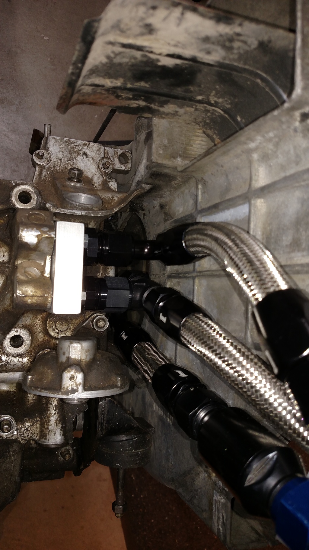
Here's the side out from the thermostat where the coolers will go in: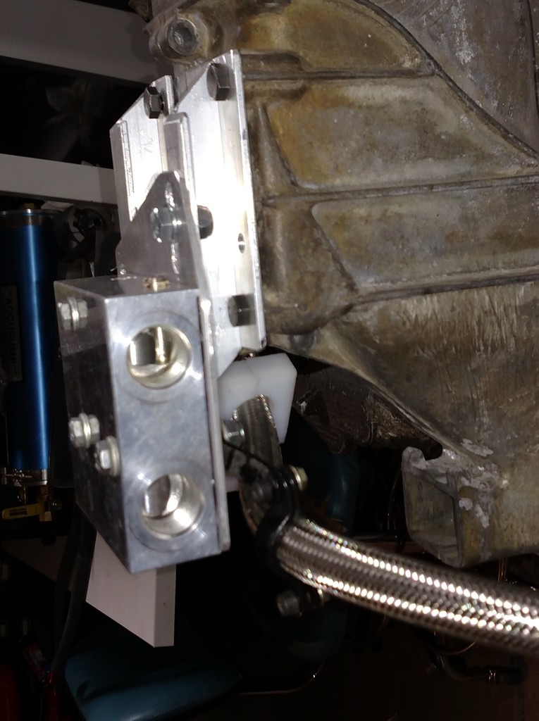
I have had that mess up under the car and it will fit once the stock cooler comes out.
I also have to contend with Murphy's law: The absoulte perfect location for all of this plumbing is where the rear suspension ear reinforcement bar crosses the engine bay to the firewall.
Makes the placement very tricky...
I hope to put it on the car this winter, but no rush.
I'll get more pics as I do that.
I will also have to add electric fans to the front coolers, but I think I have just enough room left to make it work under the headlight buckets.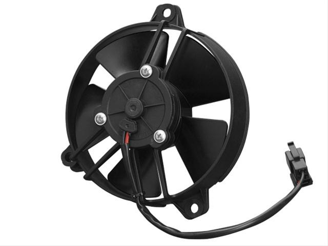
Posted by: stugray Sep 24 2016, 07:26 AM
Finally updated my drawing to match my current configuration: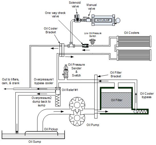
The thermostat in the pics above never actually worked right so I took it out and plumbed straight across the bracket.
If the pressure at the "low oil pressure switch" drops below ~5 PSI it opens the solenoid on the accusump.
There is a one way check valve to keep the accusump from dumping back towards an oil cooler failure.
I also have a manual valve on the accusump to avoid accidental discharge.
And I have the tangerine racing oil pressure relief valve upgrade
Posted by: Kansas 914 Sep 24 2016, 07:44 AM
Great work and write up. I need to do something on a much smaller scale on the 2143cc motor. Most of the time the temp is fine but climbing some of the LONG uphill grades around here in the Summer gets me close to the "worry point".
I think like Chris has mentioned just getting the stock oil cooler away form the original location will help and I may start with that route.
Thanks!
Posted by: N_Jay Sep 24 2016, 08:11 AM
The next stage is remote oil filter bracket with remote pressure regulator.
The CB remote filter bracket isnt 12AN size, so might go towards the Canton components.
The black "X"s indicate blockoffs, but now it is apparent that some of these applications require non-trivial solutions.
Stu
Using this diagram, if the filter plugs (or when the oil is cold) you will get very little pressure to the engine galley.
Posted by: stugray Nov 17 2016, 11:28 PM
Ok, here;s my latest:
This is right after engine disassembly.
I put the oil system back on for a sec to get a picture.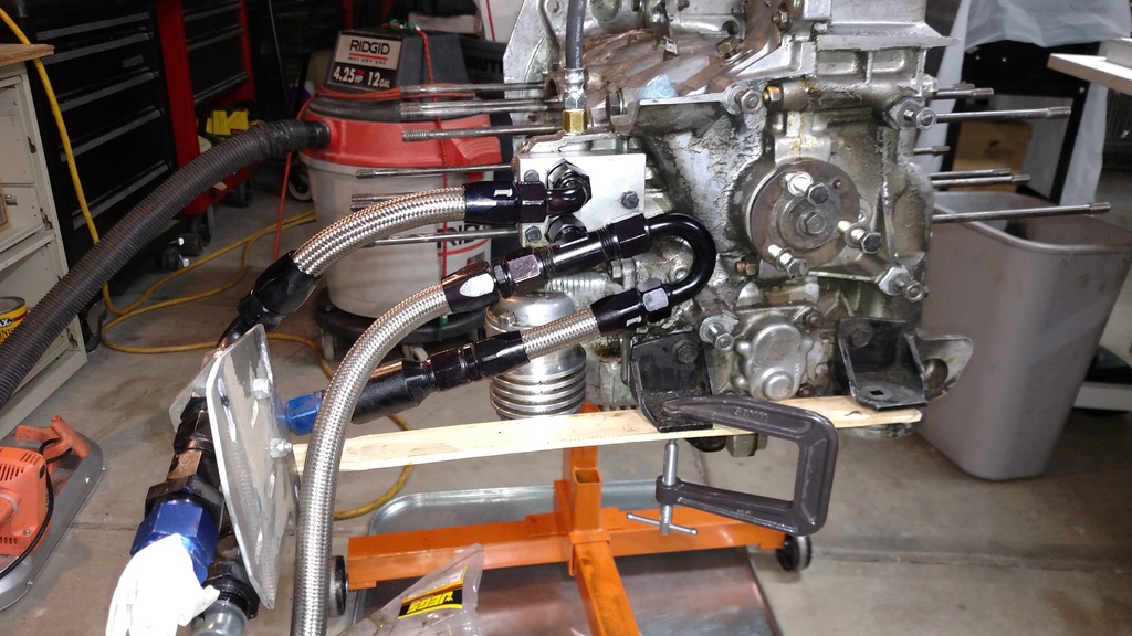
What you see is a tangerine racing oil cooler blockoff plate.
In that I have 2X 3/8 NPT X 10AN adapters
The top port is the OUT from the engine's oil pressure relief valve (Also a Tangerine racing valve insert).
This line goes to a bracket on the side of the fan housing to 12AN lines that run to the front oil coolers.
The bottom port is the IN back towards the engine.
It has the return from the oil coolers from the left, through a one-way check valve then to the tee that feeds in to the engine.
Also connected to that tee is another 10AN that comes from my accusump.
Here's a side pic: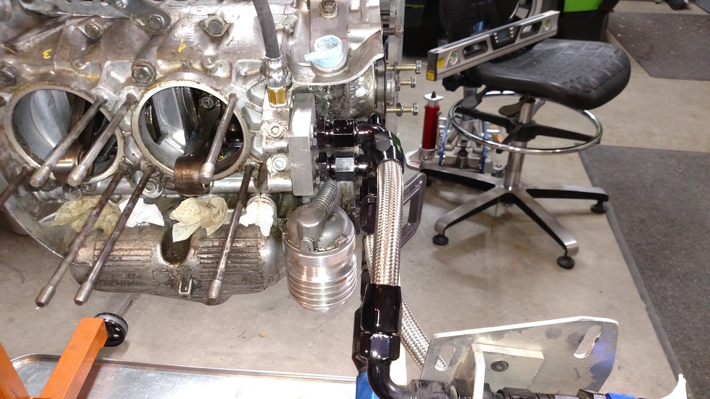
Here is a basic model of the standard OC block off plate: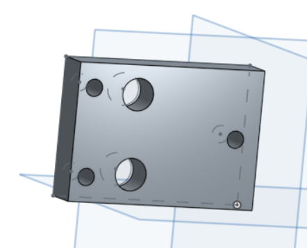
If I made a modified blockoff plate, I could eliminate a lot of that plumbing.
So here is a plate that brings the AN fitting at a 90, eliminating one turn.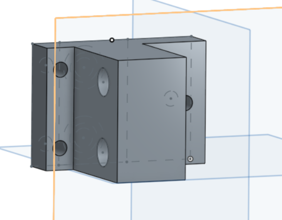
And on the back side, there would be a port for the accusump: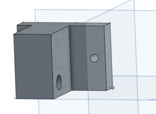
I think I will ask Cris if he can make one.
Posted by: Mark Henry Nov 18 2016, 06:40 AM
What was wrong with buying the $10 off the shelf cooler adaptor? 
Posted by: bulitt Nov 18 2016, 07:30 AM
Owned a car once with factory dry sump and the reservoir held a lot of oil (like 9 qts).
Thinking the pumps must empty the tanks pretty fast so need adequate reserve.
Posted by: stugray Nov 18 2016, 11:21 AM
What was wrong with buying the $10 off the shelf cooler adaptor?
Isnt what you are referring to what I have now?
AFAIK, the block off plate I am currently using is the most basic you can get.
I can just eliminate a lot of fittings with the new blockoff.
And if you recall me asking about using rigid 5/8 Al. tube in place of SS flex, NOW you know what I wanted to replace.
Posted by: Mark Henry Nov 18 2016, 01:19 PM
What was wrong with buying the $10 off the shelf cooler adaptor?
Isnt what you are referring to what I have now?
AFAIK, the block off plate I am currently using is the most basic you can get.
I can just eliminate a lot of fittings with the new blockoff.
And if you recall me asking about using rigid 5/8 Al. tube in place of SS flex, NOW you know what I wanted to replace.
I knew what you were doing, it's not rocket science.

I'd use seamless steel hydraulic tubing and if you wanted to be anal you could use the stainless steel flavor. Although it would take over ten years of heavy, salt spray, 4 season use before I'd worry about the regular steel hydraulic tubing. Then you could still use all your fancy fittings and some of the hose you have.
Two things I don't like about the CB dry sump pump is the pressure side only has 21mm gears and it has a aluminum cover.
In my book aluminum covers are garbage and I've seen excessive premature wear in less than 1000 miles.
Powered by Invision Power Board (http://www.invisionboard.com)
© Invision Power Services (http://www.invisionpower.com)