Printable Version of Topic
Click here to view this topic in its original format
914World.com _ 914World Garage _ making some progress on my sbc 307 V8 car
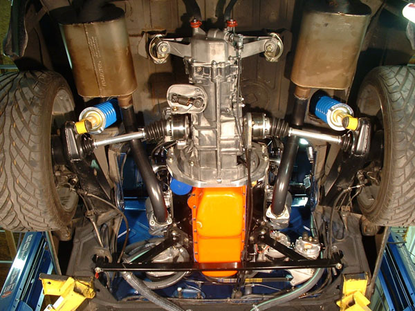
Posted by: jimkelly Sep 16 2013, 12:45 PM
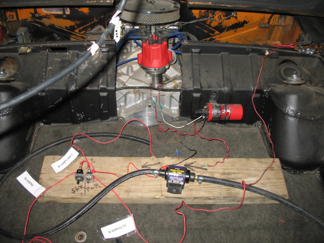
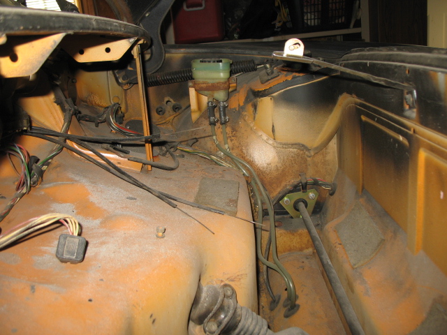
wiring my v8
and tell me what I have wrong or missing.
my bad for never labeling the wires 
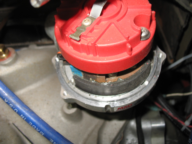
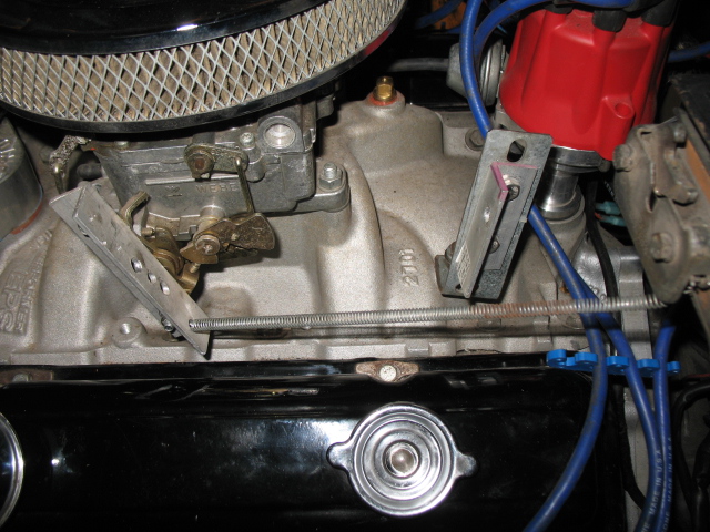
distributor is msd 8360
but you guys are smart 
and yes - I better connect that oil guage line or I will have a mess on my hands.
Attached thumbnail(s)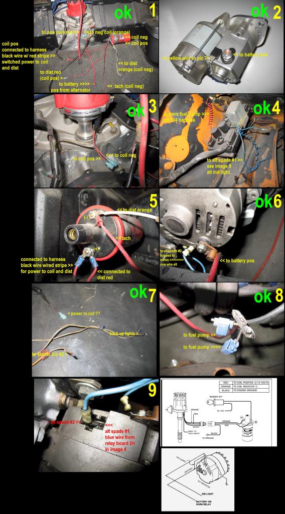
Posted by: 3d914 Sep 16 2013, 01:01 PM
IIRC the yellow wire goes to the positive side of the starter solenoid - what you labeled as ingition switch/pos toggle.
Posted by: jimkelly Sep 16 2013, 01:05 PM
thank you - I am editing my collage as we go.
jim
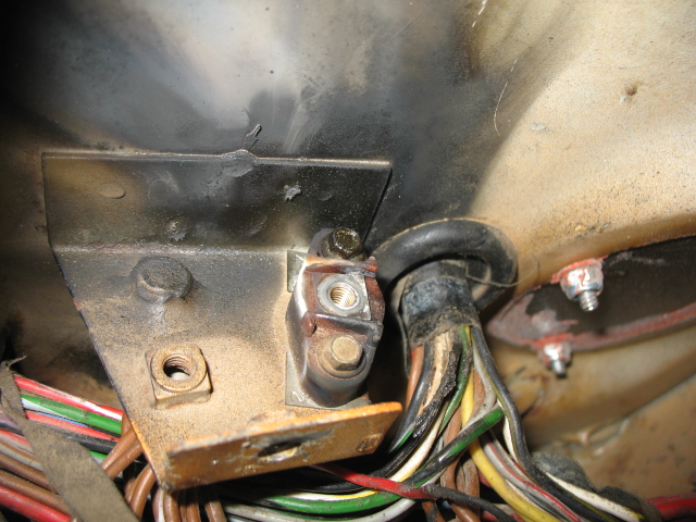
Posted by: Spoke Sep 16 2013, 02:13 PM
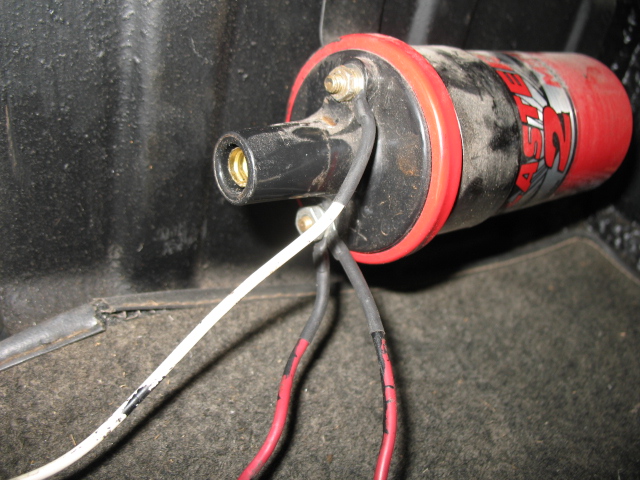
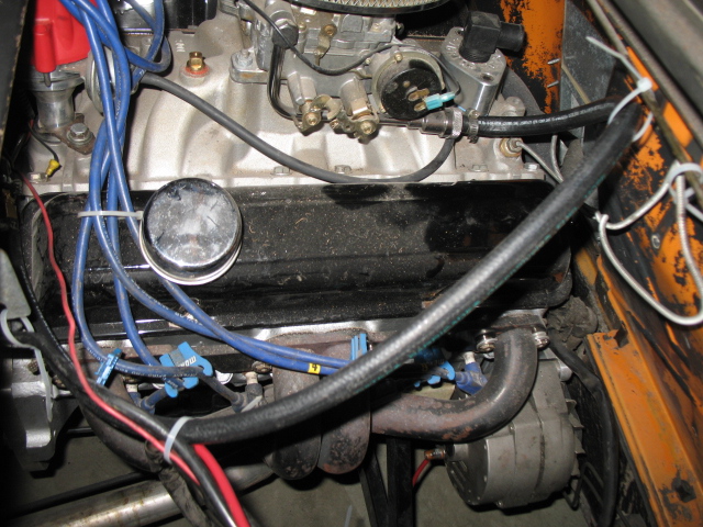
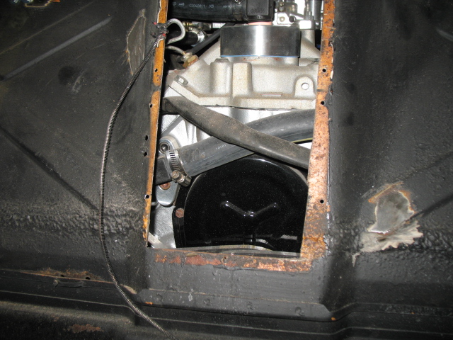
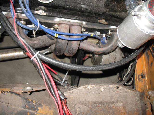
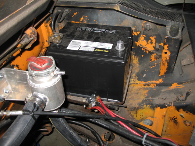
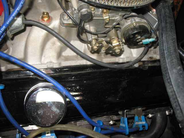
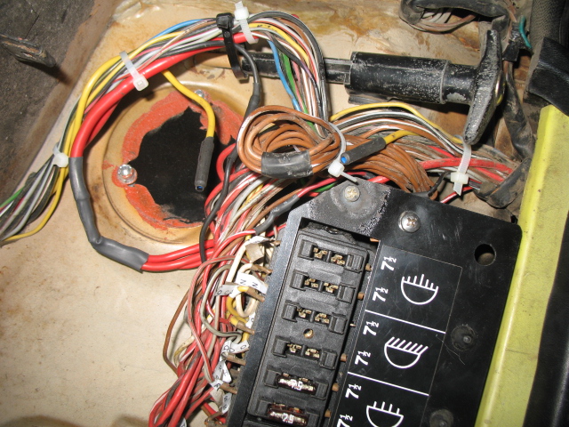
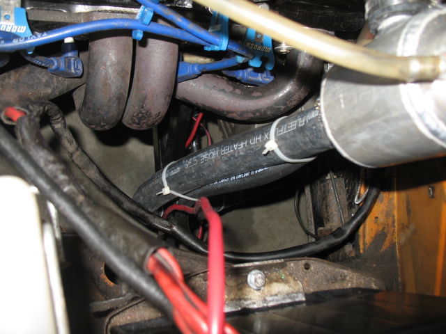
Page 5: Red wire from harness is 12V power to coil and distributor.
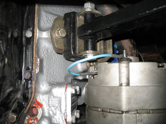
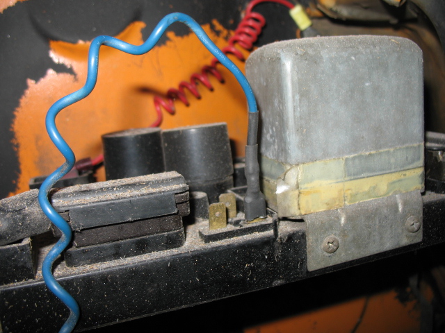
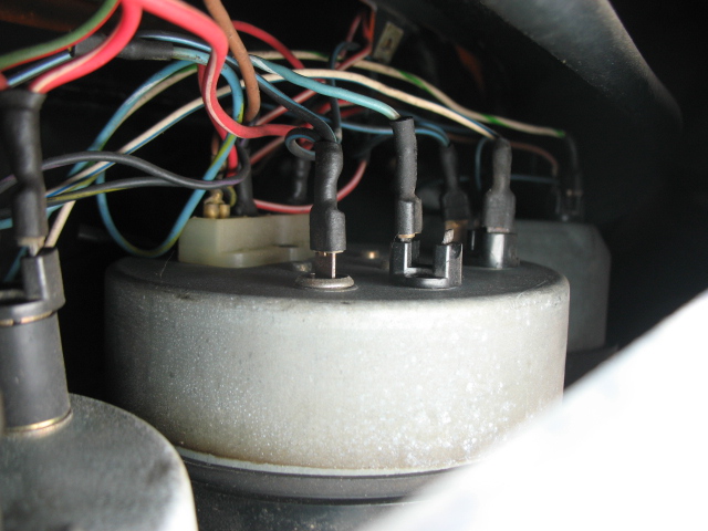
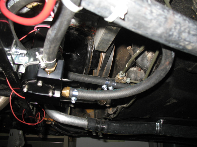
Page 6: Blue wire is from original voltage regulator. Unless that goes to a sender on the new alternator, you don't need this. You also don't need the original voltage regulator.
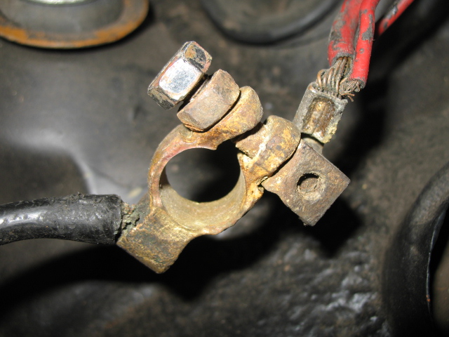
Page 6: The red wire to the battery doesn't look good at that terminal block. Also you need some sort of rubber cover for that connection. Touching that to any grounded point will result in fireworks as there is nothing to limit the current from the battery except the wire.
Page 6: Where does the blue wire go?
Posted by: jimkelly Sep 16 2013, 02:30 PM
spoke
I am pretty sure my ignition switch was partially bad - I had it partially bypassed and rigged with alternate switches but will replace the ignition switch asap.
and thank you for that other info!!!
the red wire to positive coil and distributor coming from harness, comes off this black wire with red (or maybe orange) stripe. makes sense.
I think I am using the black/red wire (fuel pump wire) for switched power??
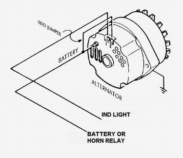
http://www.914world.com/bbs2/index.php?showtopic=18407&hl=alternator+indicator+light
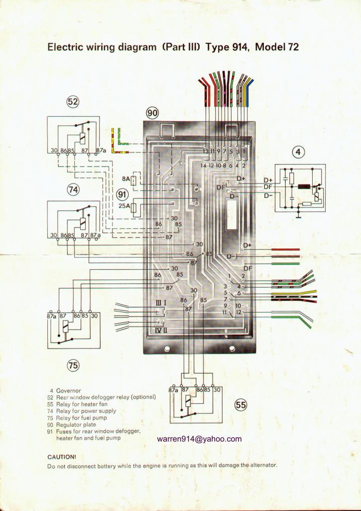
1 = yellow, power to the starter
2 = blue, from alternator indicator light to D+ (red) on alternator harness
3 = grey/brown, from brakelight switch
4 = grey/brown, to brakelights
5 = green/red, oil-pressure sender to oil-pressure warning light
6 = not used
7 = black/purple, to tachometer, comes from pin #1 on coil
8 = black, from fuse #8, power for relays, goes to pin #15 on coil
9 = green/white, from heater blower switch to blower
10 = brown, to main ground connector
11 = green, to heater fan
12 = red, to battery
13 = black/red, to fuelpump
14 = red, to battery
Attached image(s)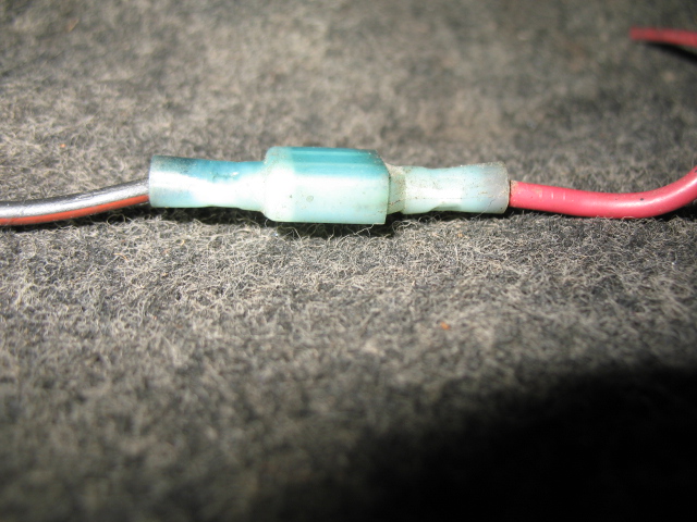
Posted by: jimkelly Sep 16 2013, 07:31 PM
spoke
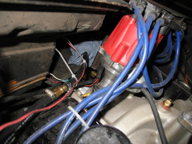
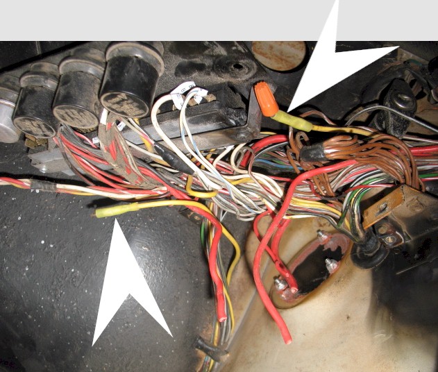
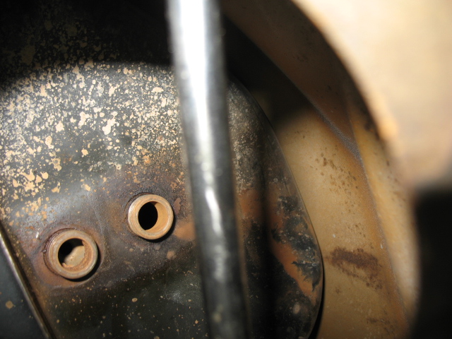
image 6 - the blue wire loops around and connects to one oft eh two recessed spades.
I think this threat explains the thinking behind it.
http://www.jalopyjournal.com/forum/showthread.php?t=687122
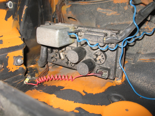
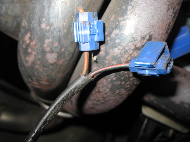
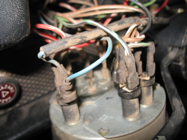
I wonder if my blue wire in image 4 went to my alternator?
this thread indicates that alt ind light is pin D+ on relay board which appears where my blue wire is connected in image 4.
http://www.914world.com/bbs2/index.php?showtopic=18407&hl=alternator+indicator+light
Attached image(s)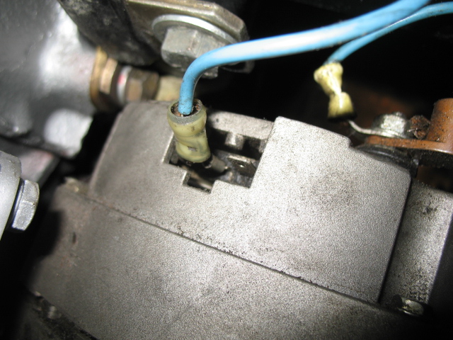
Posted by: jmmotorsports Sep 17 2013, 04:15 AM

spoke
I am pretty sure my ignition switch was partially bad - I had it partially bypassed and rigged with alternate switches but will replace the ignition switch asap.
and thank you for that other info!!!
the red wire to positive coil and distributor coming from harness, comes off this black wire with red (or maybe orange) stripe. makes sense.
buy a renegade harness save tourself a lot of troublej
Posted by: chads74 Sep 17 2013, 06:19 AM
spoke
I am pretty sure my ignition switch was partially bad - I had it partially bypassed and rigged with alternate switches but will replace the ignition switch asap.
and thank you for that other info!!!
the red wire to positive coil and distributor coming from harness, comes off this black wire with red (or maybe orange) stripe. makes sense.
buy a renegade harness save tourself a lot of troublej
I got the renegade harness and it was VERY easy to install. I ended up not using a couple of the wires, but it plugged right into the relay board and tells you exactly where the wires go. Took about an hour to run all the wires.
Posted by: dwillouby Sep 17 2013, 06:42 AM
I dont use the relay board. You need a switched 12 v and 12 v starter signal. Installed a 1 wire alt. I am using a MSD / Mallory system with Fast fuel injection. Very simple wiring setup
David
Posted by: Spoke Sep 17 2013, 06:49 AM
spoke
image 6 - the blue wire loops around and connects to one oft eh two recessed spades.
I think this threat explains the thinking behind it.
http://www.jalopyjournal.com/forum/showthread.php?t=687122
I wonder if my blue wire in image 4 went to my alternator?
this thread indicators that alt ind light is pin D+ on relay board which appears where my blue wire is connected in image 4.
That makes sense. That blue wire goes to the GEN light and to the open spade on your alternator.
You can remove the voltage regulator as that function is done inside of the new alternator.
Posted by: jimkelly Sep 17 2013, 07:03 AM
I was thinking that since it seems to be the only male spade remaining.
main image revised again.
thanks
jim
Posted by: jimkelly Sep 17 2013, 08:01 AM
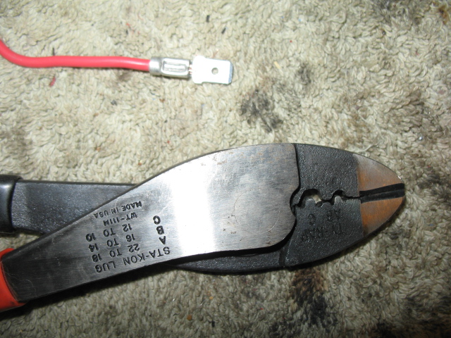
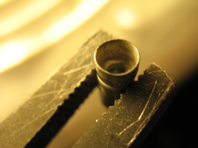
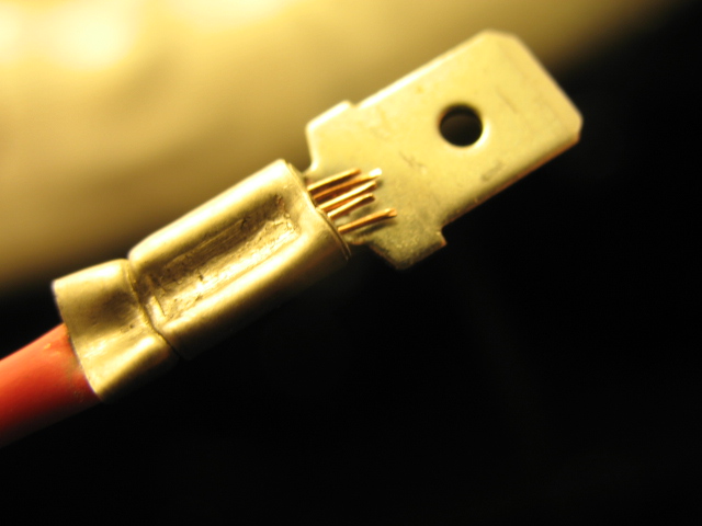
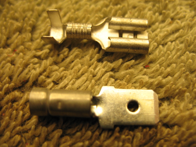
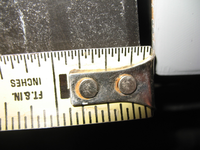
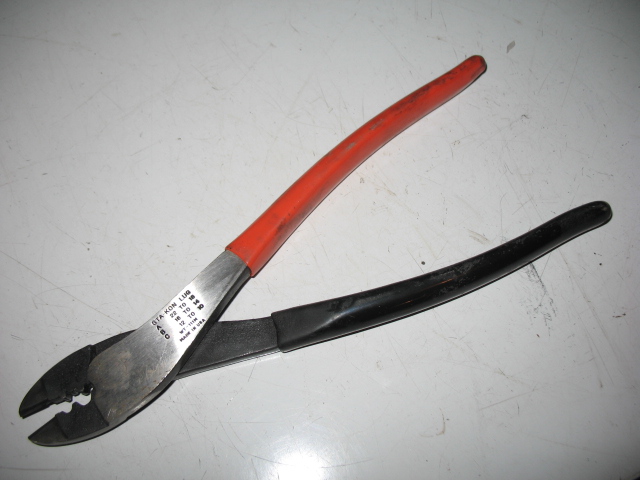
finally going to put my crimper and heat shrink to good use.
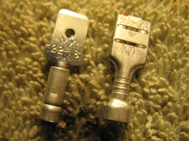
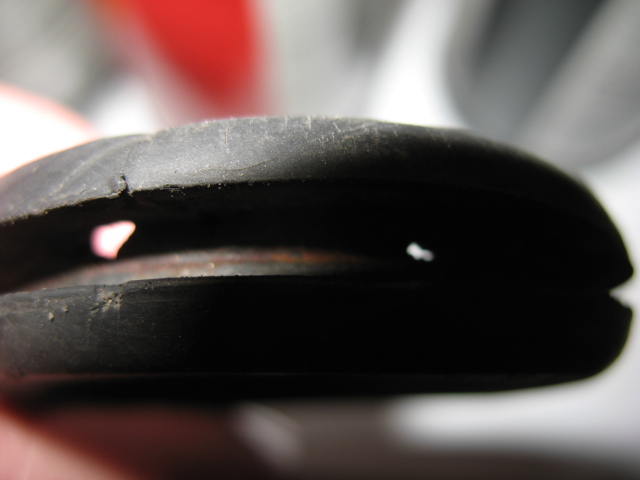
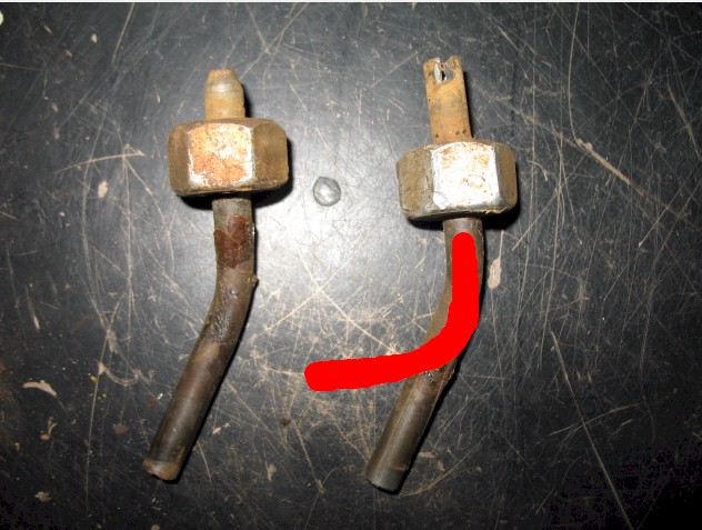
though I am not liking that the male double crimp connector has a different DOUBLE CRIMP portion than the female.
in fact, it seems to me, that the napa tool does not work on this male connector and despite mcmaster carr selling them as double crimp, I don't feel they are truly double crimp, as they don't really provide as decent of stress relief as the female's as they don't crimp well onto the wire insulator.
it seems to me, that my other crimp tool is better for these male's. see pics.
and some connector clean up.
preparing to start engine.
Attached image(s)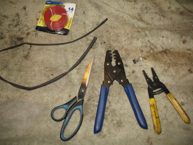


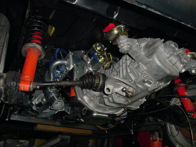
Posted by: jimkelly Sep 20 2013, 12:45 PM
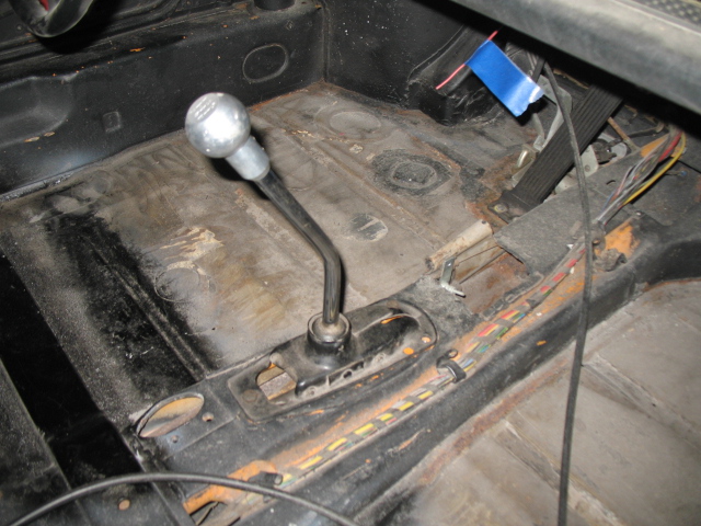
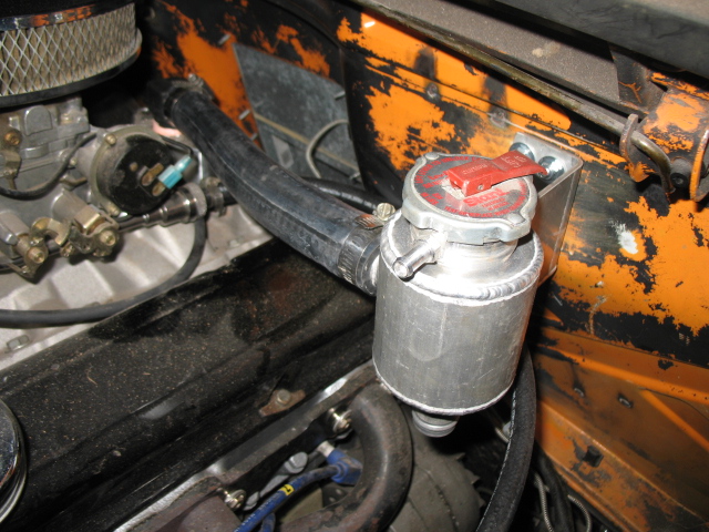
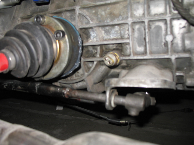
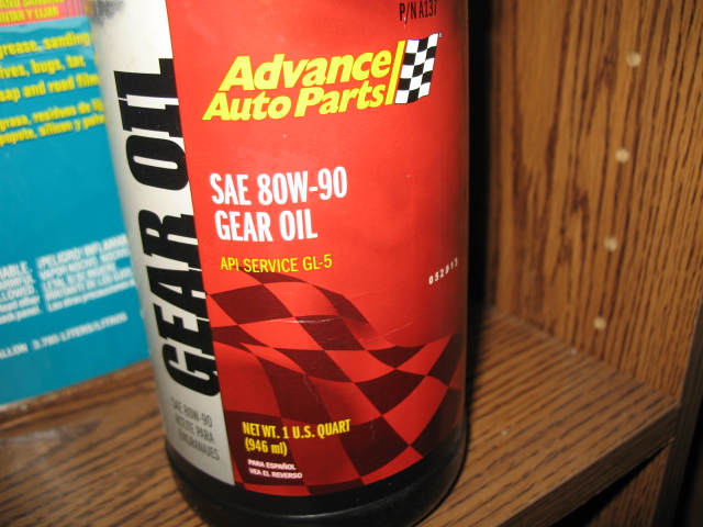
starter, shift linkage, gear oil, coolant fill neck, installed
Monday I swap out the early for late soft front passenger side brake line and add fluid and bleed.
for a whole this morning, I thought I had the firing sequence all buggered up, but after looking at it over and over again, i think it is ok.
waiting on ebay to deliver my CHROME dip stick and tube, I am sure engine is empty.
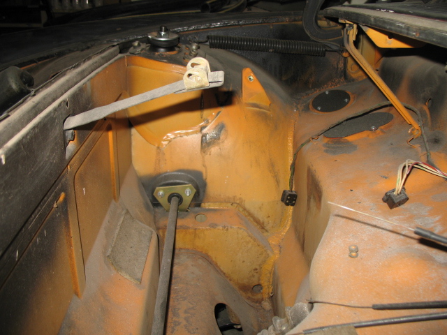
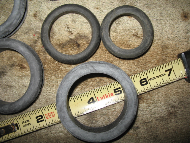
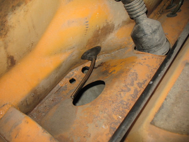
getting the correct grommets for front trunk is hell!!! one hose is 1.5 ID and the other is 1.7 ID, the bigger one is more of a challenge and the thicker the better as to have more rubber between hose and sheet metal, as mu old thinner grommets wore thru.
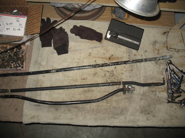
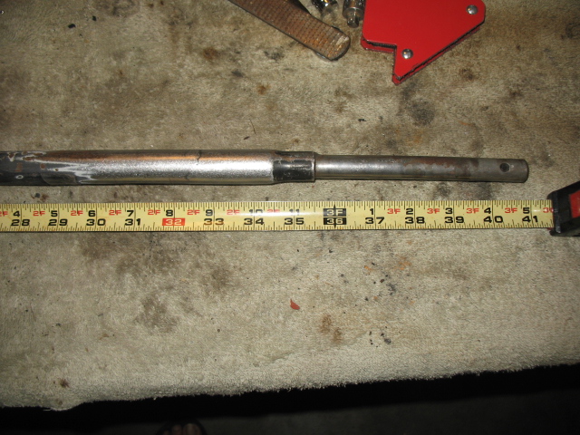
stock engine bay shift bar is 39.25" and renegade suggests adding 1.5" to this. the modified bar I have is 40" and should be fine but I will try to weld up a new straight one. as before I was using a custom engine bar, not renegade's..
Attached image(s)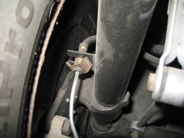
Posted by: 76-914 Sep 20 2013, 02:19 PM
Jim, are you doing this and the Suby conversion or did the Suby get shit canned?
Posted by: jimkelly Sep 20 2013, 03:24 PM
I simply want to get the 1972 V8 running and functional - and then I want to focus, as resources allow, on my 1975, to be suby powered.
in all honesty, the V8 sucks gas and shifts like a 914.
I look forward to NOT SUCKING and SHIFTING modernly 
now that I have a MIG up and running, I feel much more confident.
thanks
jim
Attached image(s)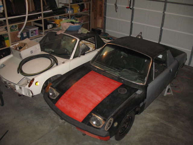
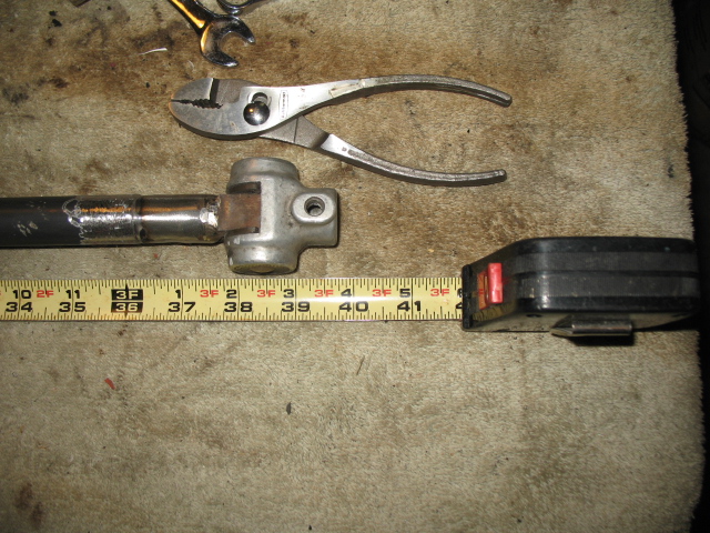
Posted by: jimkelly Sep 21 2013, 08:34 AM
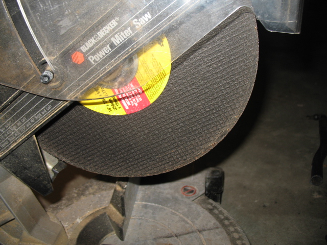
just goofing around, since I already have a bar that fits.
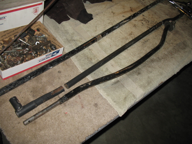
I put a cut off wheel in my mitre box and cut some tailshift linkage and side shift linkage, both engine bay rods.
correction: cutting both bars just before the bends will give me a modded bar almost exactly 39.75" long tip to tip, 1" too short - i will ad 1", to get to 40.75". stock is 39.25".
note: it is odd that the side shift engine bay bar is neither totally straight, nor are the holes for the conical screws perfectly lined up. I will be ignoring this, since both are cocked ever so slightly.
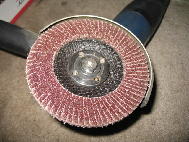
also, I have to say, a flap disc kicks ass. grinds better than a grinding wheel in many cases. never expected that.
Attached image(s)
Posted by: zambezi Sep 21 2013, 12:31 PM
yes they grind better and produce less heat. Easier to control the amount you are grinding too so you don't grind away too much.
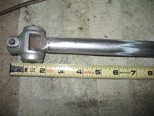
Posted by: jimkelly Sep 21 2013, 01:15 PM
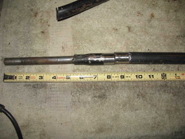
engine bay shift rod done : )
40.75"
it is pretty darn straight, but I think the tang that goes into the console is tweaked - so I will tweak it back to straight a tiny bit.
and got my dip stick in the mail - made in korea of all places - and of course it won't seat fully, about 1/4 inch shy.
I found that after grinding an area, taking a DA sander to the area, makes it real nice.
ok - she is in - and she is pretty ; )
Attached image(s)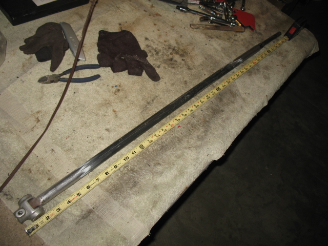
Posted by: jimkelly Sep 22 2013, 11:22 AM
some random pics
Attached image(s)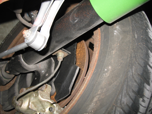
Posted by: kg6dxn Sep 22 2013, 07:17 PM
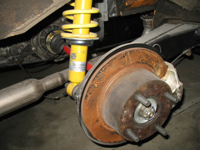
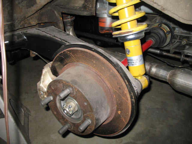
Your lower spring perch is upside down... 
Posted by: jimkelly Sep 22 2013, 07:45 PM
thanks for that!!!
jim
Posted by: jimkelly Sep 23 2013, 07:41 AM
don't be an idiot like me.
anyway, one flipped and one left to do, waiting on bushing from bdstone : )
Attached image(s)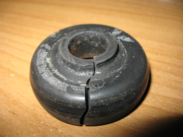
Posted by: 76-914 Sep 23 2013, 03:04 PM
Is that a "red" ground wire? 
Posted by: jimkelly Sep 25 2013, 09:27 AM
from the relay board to the body? yes. I will change it.
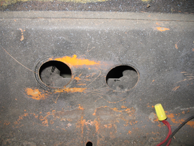
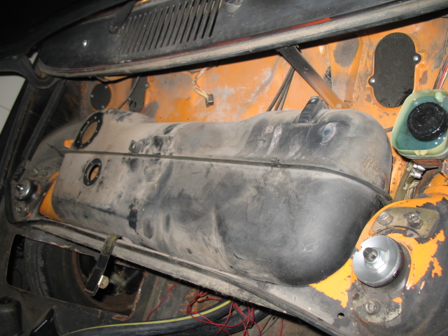
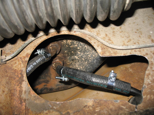
side note: as for the water lines. the exactly correct grommets are a bitcvh to find, so I bought a few of these 2" ID grommets (ebay item # - 261171010853) on ebay cheap, and they will allow me to add some rubber around my hoses to give them even better protection. because my original, properly sized grommets wore thru, and I want to avoid any chance of my hoses getting damaged from contact with sheet metal.
pic shows my orig grommets used and how much sheet metal I need to grind away in order to install the 2" ID ones I just got. need to get a rasp bit.
hoses are 1.4" OD and 1.7" OD.
Attached image(s)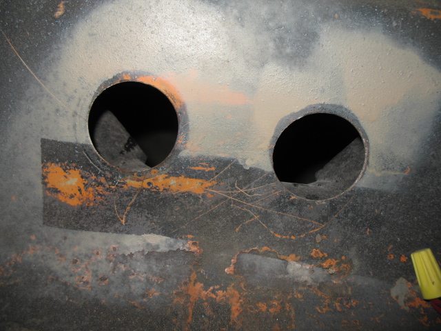
Posted by: jimkelly Sep 25 2013, 09:35 AM
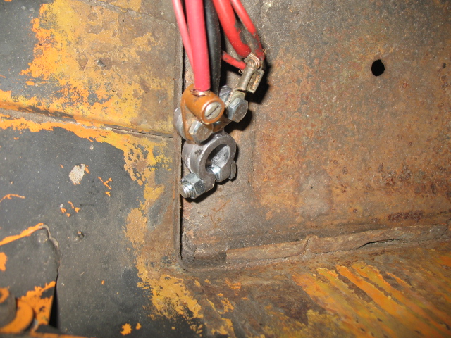
also - before, I had the pos from alt running to pos on starter.
I guess it can be routed this way or directly to pos on battery?
Attached image(s)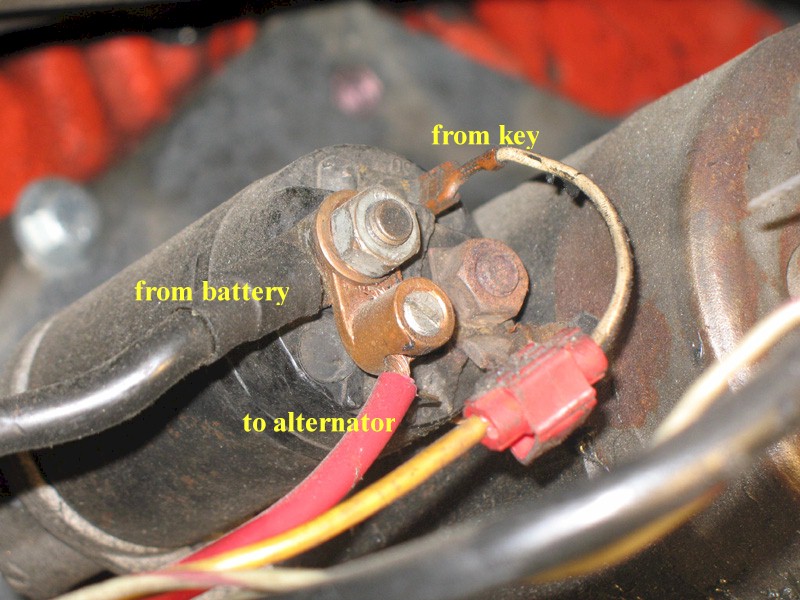
Posted by: kg6dxn Sep 25 2013, 09:01 PM
also - before, I had the pos from alt running to pos on starter.
I guess it can be routed this way or directly to pos on battery?
It can be routed that way but... Crimp a ring on the red wire. Get rid of that mechanical lug; bad things will happen... Replace the "scotch lock" (bad things will happen) fitting on the yellow wire with a butt splice or solder & shrink tube. Finally replace the white wire with a wire the same gauge as the yellow one.
Posted by: jimkelly Sep 26 2013, 09:34 AM
mike - I will get those wires buttoned up - thanks.
and thanks to bdstone914 for some needed parts.
Attached image(s)
Posted by: jimkelly Sep 29 2013, 08:25 AM
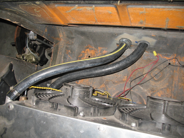
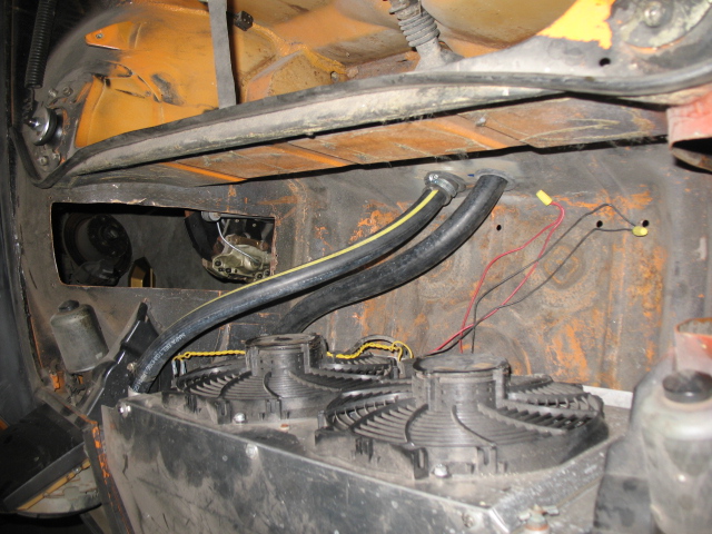
guess i'll run the coolant lines today. the 2" ID gommets will be fine. I was able to wrap the 1.5" OD hose fully with old hose, but the 1.75" OD does not leave a big gap but I will stuff some rubber in there.
while I take a break from bleeding my brakes. THREAD LINK
http://www.914world.com/bbs2/index.php?showtopic=220851
Attached image(s)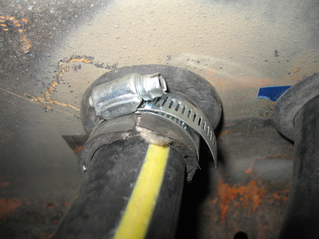
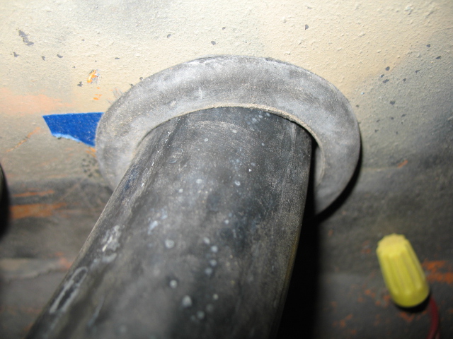
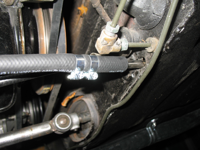
Posted by: jimkelly Sep 29 2013, 03:14 PM
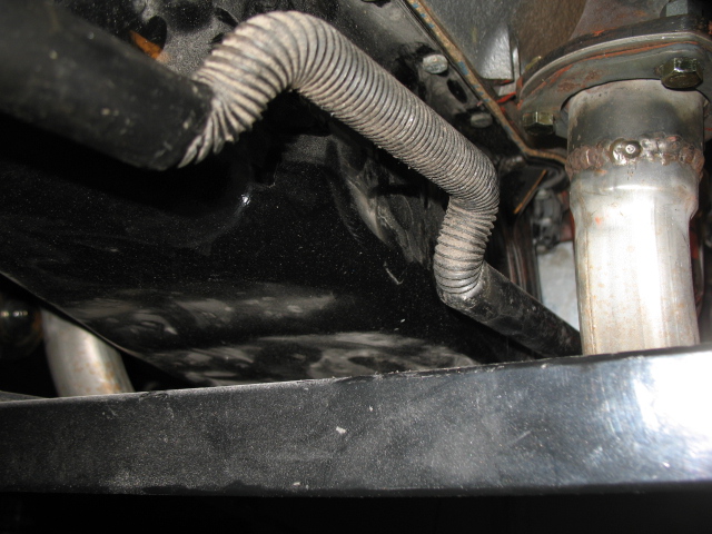
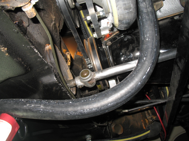
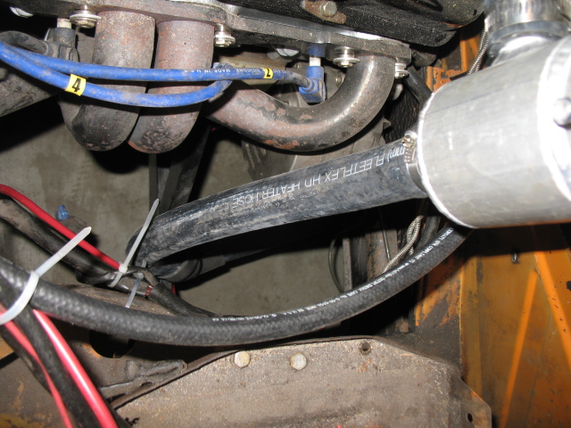
well, not sure I like the relatively short 90 degree bend of the large hose from under car to water pump, a curved tube of aluminum would be real nice here.
also, what could I put on the smaller hose that will reside only 4-5 inches from exhaust header?
BTW: sheet metal sheers cut thru coolant hose very nicely.
I found this 90 degree 1-1/4 OD bend on ebay and bought it.
Attached thumbnail(s)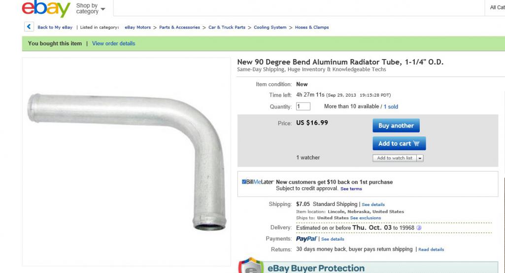
Attached image(s)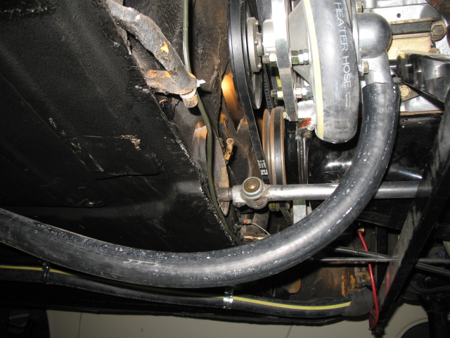
Posted by: bulitt Sep 29 2013, 06:33 PM
I may have to get one of those 90's.
Posted by: jimkelly Sep 30 2013, 07:32 AM
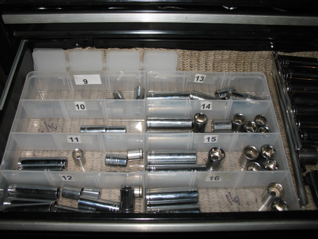
since the only electrical connector I have, that has strain relief, is a female connector, I have been removing the insulators from my crappy connectors, crimping them and then heat shrinking them, to give these single crimp connections some weather protection and some amount of strain relief. like mcmark does, I always try to use narrow heat shrink and on top of that, next size up on all connections.
and today I organized my metric sockets - seems I have a 10mm shortage : (
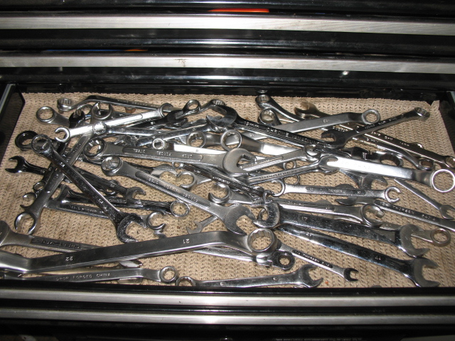
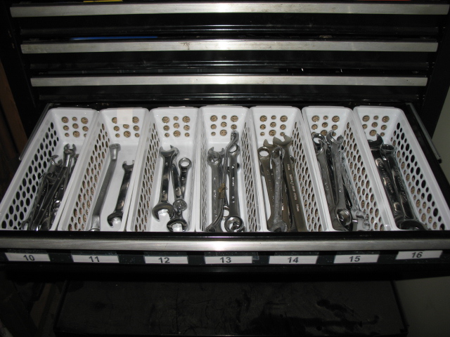
I still need to organize my wrenches.
Attached image(s)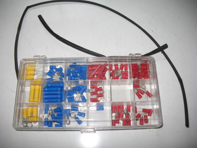
Posted by: jimkelly Oct 2 2013, 09:18 AM
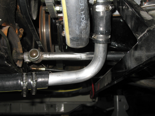
rcvd the 90 degree tube today - looks good.
Attached image(s)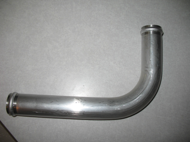
Posted by: andys Oct 2 2013, 09:26 AM
Much nicer with that aluminum 90!
Andys
Posted by: speed metal army Oct 2 2013, 10:05 PM
Hey Jim, weather pack electrical connectors are a cool solution that stays nice and clean. There is a few on my car. The spades are history! 
Posted by: jimkelly Oct 7 2013, 11:41 AM
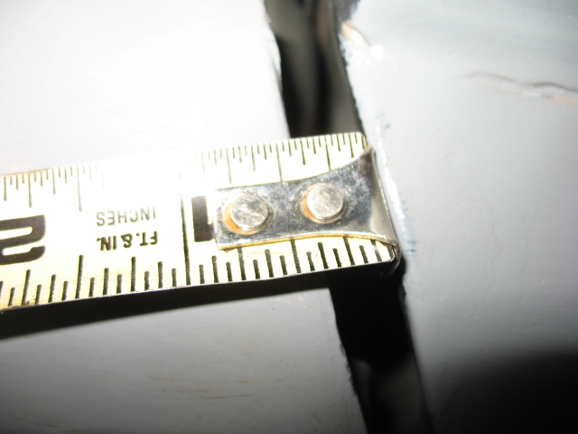
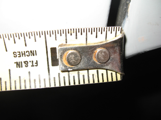
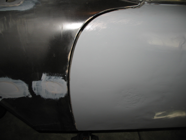
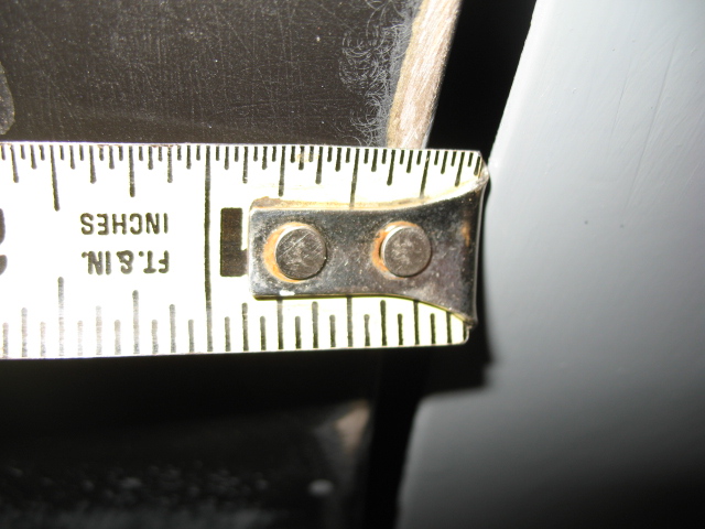
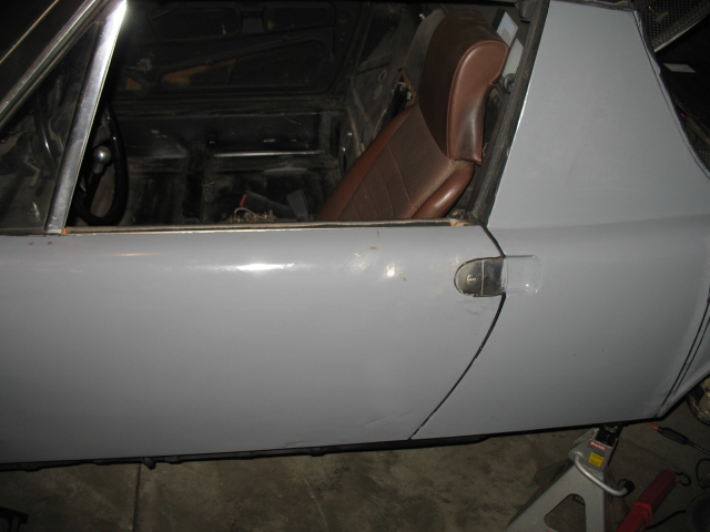
well, my car had a big gap, at top, between the drivers side door and the rear fender. I've been thinking of using a cut off wheel and cutting around the long, top and both sides, letting car settle into the gap, and welding the seam back up. but today I decided to add few washers to the door hinge as a less invasive approach. prior to today, door had to be slammed BRUTALLY HARD to close, but after washer treatment, 2 at top and 1 at bottom, and door closes nicely now. good enough for me.
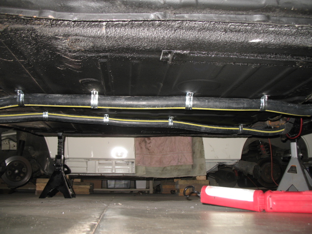
next step is add coolant to cooling system, get a battery, and see if she starts.
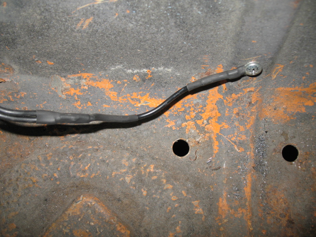
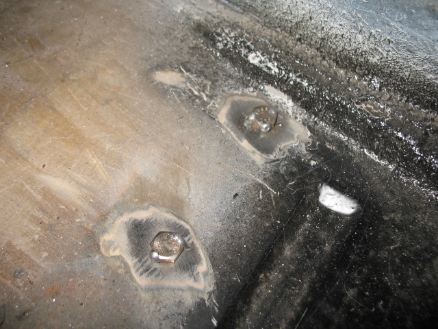
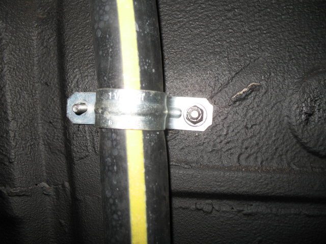
I decided to lose the sheet metal screws and replace with bolts tacked to the floor (so hose install/removal is a one man job), a washer and a nylock nut. the sheet metal screws' pointy top protruding into thru the cabin floor was an issue.
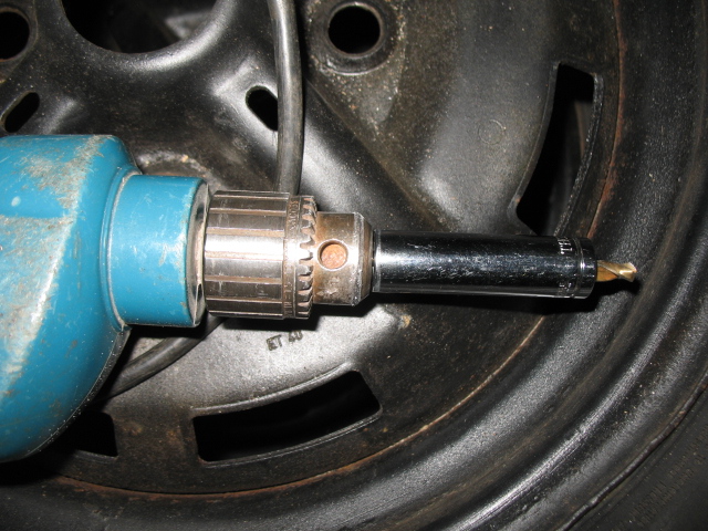
socket on drill bit when you only want to go thru but not full bit depth.
Attached image(s)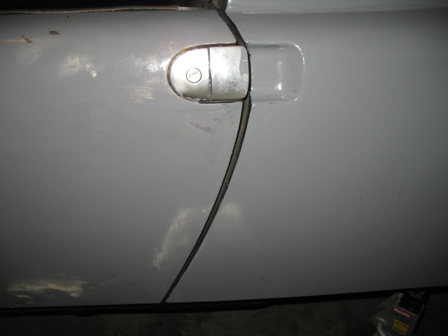
Posted by: JRust Oct 7 2013, 08:11 PM
Yeah the aluminum 90% was a good move. I didn't like that bend with the gates hose either. I found a formed hose at the parts store to run from the firewall up. It was perfect from my buick setup. Looking good 
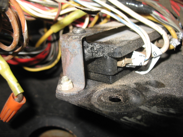
Posted by: jimkelly Oct 9 2013, 01:12 PM
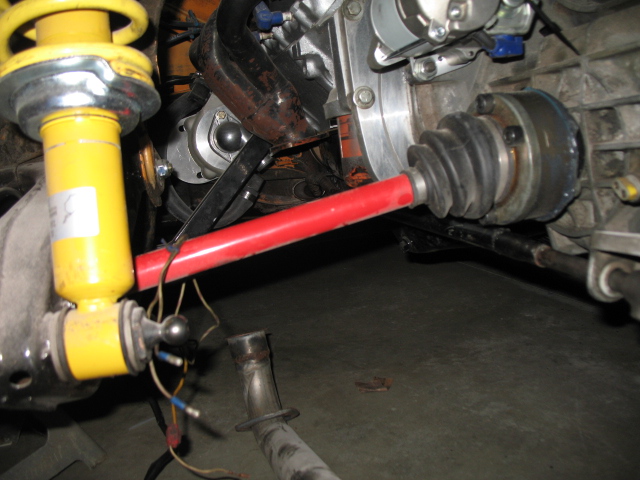
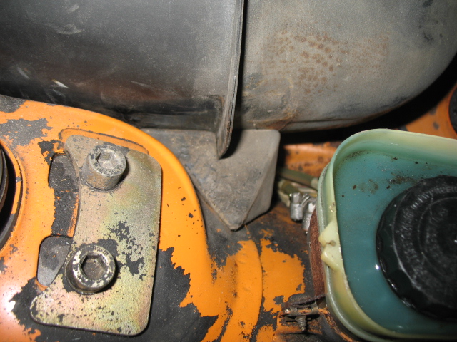
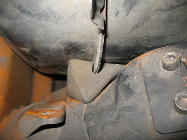
well two issues.
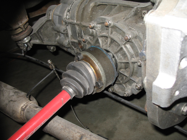
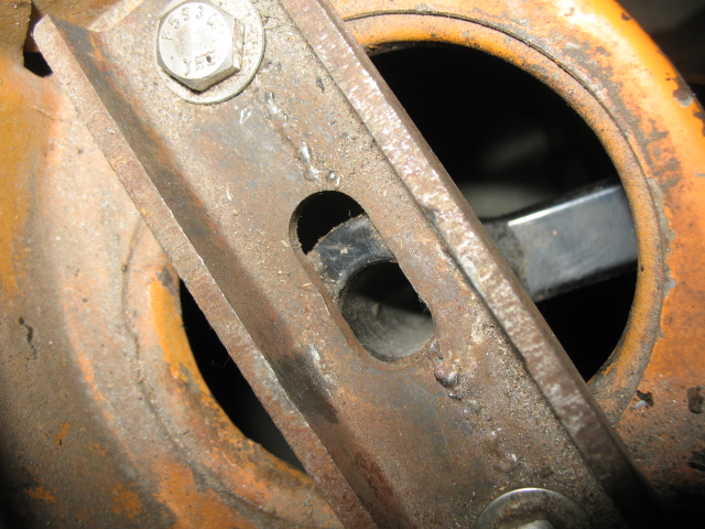
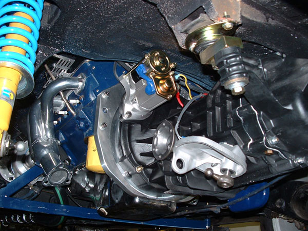
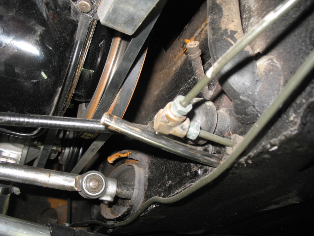
I need to either come up with a washer solution for the top bracket for engine mount, or I can just replace with rectangular steel and use longer main bolt. looking at the pic, I think I will get to perfect thick washers and grind the sides down so they will fit into the recess, might need 2 or three on each side.
second, do I need to move lower rear tranny mount washer to just above trans? right now it is just above the conversion/set back plate, above trans ear.
while making this video I realized I had some eng/trans movement.
https://www.youtube.com/watch?v=MEZGsCXrBCw
found this pics..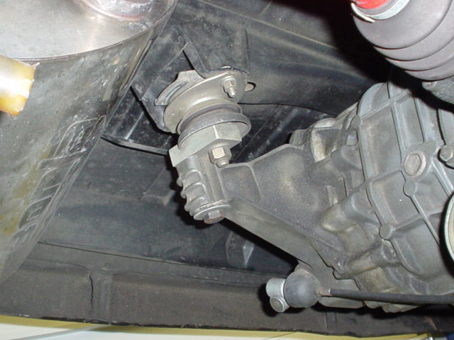
Attached image(s)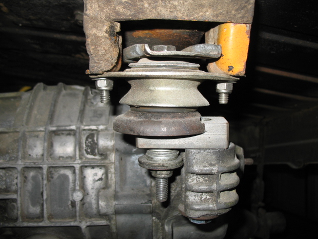
Posted by: JRust Oct 9 2013, 03:17 PM
The big washer with the groove goes on the bottom of the tranny ear. The groove to the inner side of the ear. The way you have it the tranny can slide right back off the bolt.
Posted by: jimkelly Oct 9 2013, 04:57 PM
I have been searching and have yet to find a pic or drawing that has this washer at bottom of trans. but I see it belongs at top of trans under normal circumstances. though I can see where putting it at bottom in this circumstance makes sense.
Attached thumbnail(s)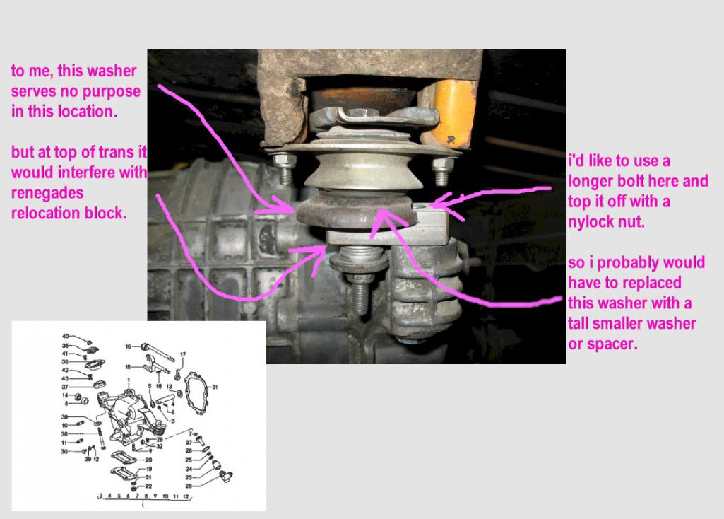
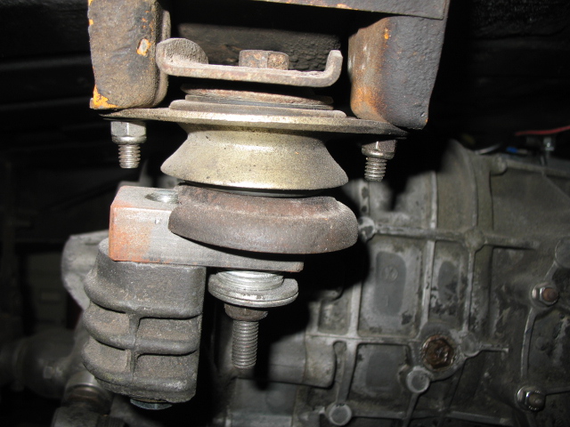
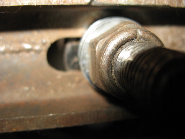
Posted by: jimkelly Oct 10 2013, 06:29 AM
instead of this jumble of parts, I am thinking of installing a piece of 2" x 2" x 1/4" square steel tube which will require 3 holes and allow me to put a nylock nut on top of the bolt going thru the trans ear. reusing all hardware, just need the nylock nut.
Attached thumbnail(s)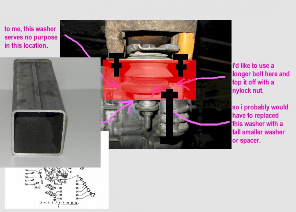
Posted by: bulitt Oct 10 2013, 06:50 AM
I'm thinking you will break your trans ears off if you go with a solid tube.
Heres some pics from Renegade site.
Posted by: JRust Oct 10 2013, 07:20 AM
I have been searching and have yet to find a pic or drawing that has this washer at bottom of trans. but I see it belongs at top of trans under normal circumstances. though I can see where putting it at bottom in this circumstance makes sense.
Your right it is on top normally. I think it will still sit on top fine with renegade's block on top. Been a while since I messed with mine. I believe the lip it leaves will work. I may have used mine on the bottom flipped to accomplish the same thing. I guess it's worth trying both. Give Steve at Renegade a call

Posted by: jimkelly Oct 10 2013, 07:34 AM
for engine mounts, found washers that fit perfectly at ACE : )
and I agree about concerns of breaking off trans ear. certainly would have to make sure to loosen trans mount bolts BEFORE engine mount bolts, before tilting eng/trans assy at all. though I may just leave it as it is? maybe I just need a robust lock washer on the bolt going up thru the trans ear and into the renegade block as it appears some have done.
still getting some eng/trans shifting when shifting thru gears?
and I do see my rear most trans bushing is shot.
https://www.youtube.com/watch?v=g_p4-mUkC-I
Attached image(s)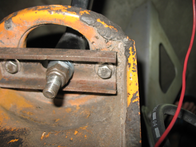
Posted by: Chris H. Oct 10 2013, 09:43 AM
Hijack but this exhaust setup is AWESOME 
That's how I eventually want to connect mine from the muffler exits back.
Posted by: jimkelly Oct 10 2013, 09:51 AM
good point. behind trans is where the most space available for a cross over, I agree it is a good design and over axles is nice too, all tucked up.
shorter mufflers are the key and my hugger headers are NOT a good starting point.
but skline had a nice clean set up too. a 2 in 2 out muffler.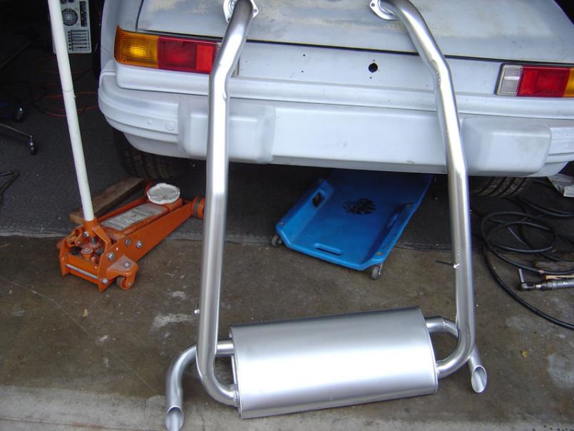
Attached thumbnail(s)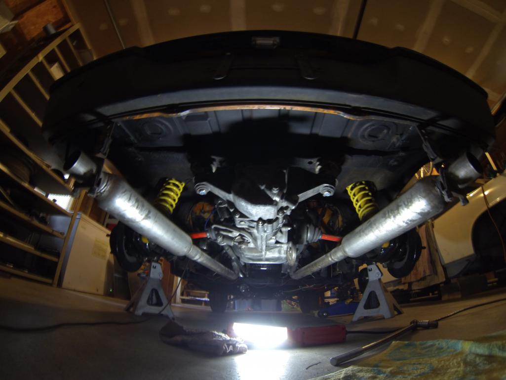
Posted by: mittelmotor Oct 10 2013, 01:22 PM
I like the 2-in/2-out approach as well. Keeps the sound level reasonable. Note hidden dump pipe on far side for stealth (relative term here for V-8 conversions!).
Attached image(s)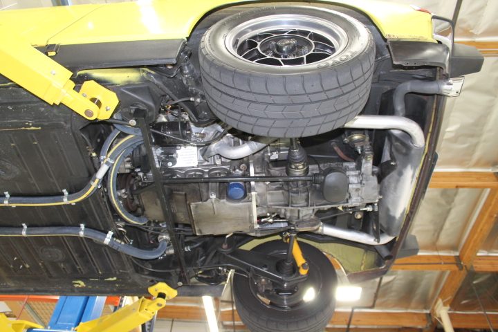
Posted by: jimkelly Oct 10 2013, 01:41 PM
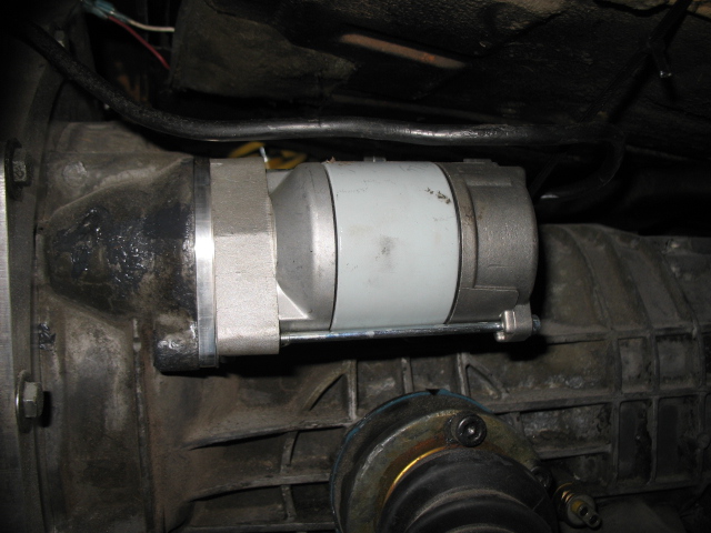
well, finally got a battery today. hooked it up, and tested the starter. engine cranked over nicely (starter seems to be fully engage flywheel teeth - whew) and fuel pump ran. maybe tomorrow i'll stick the gas line into a gas can and fill the cooling system, and see if she starts. hopefully the timing is not too far off.
Attached image(s)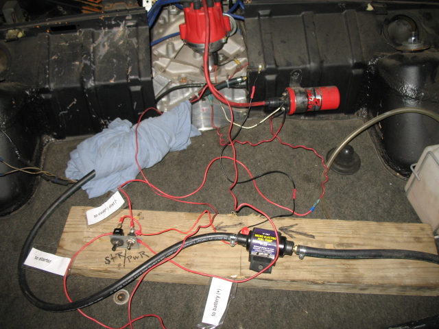
Posted by: jimkelly Oct 11 2013, 07:24 AM
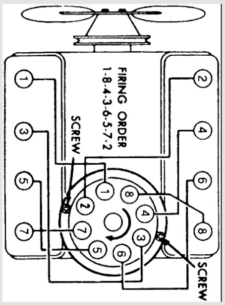
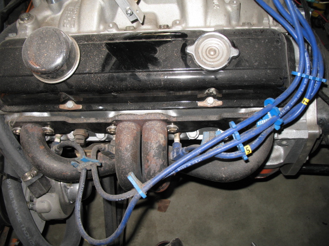
hooked my fuel to gas but she backfires and pops. I am sure I have my spark plug wires wrong.
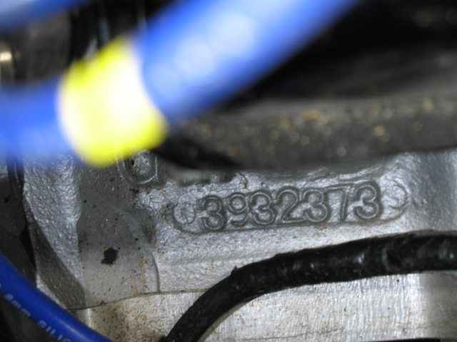
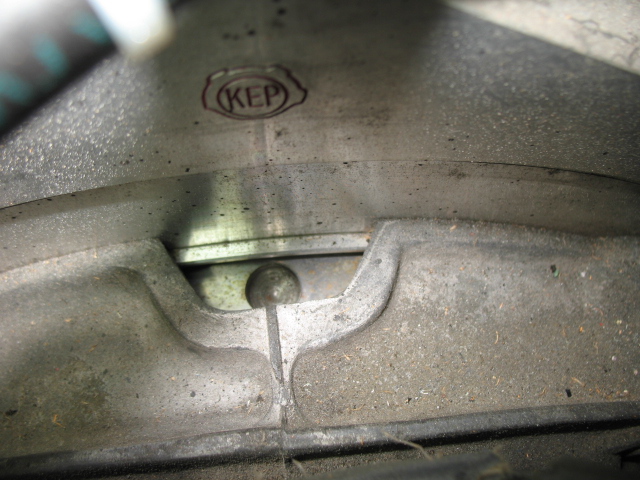
is it safe to say that if the notch on the front pully is directly up, then where the rotor points is #1 ?? engine is a 307. #3932373
she sputtering and back firing but not starting 
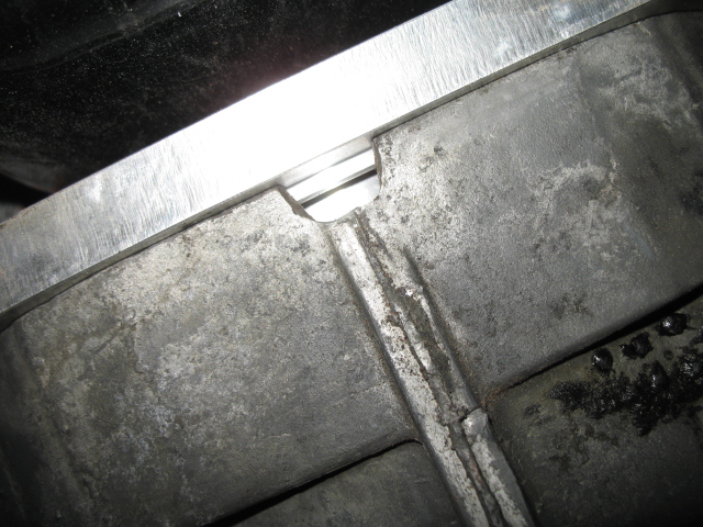
or is this round mark at top of flywheel the tdc mark, indicating #1?
the pulley mark when at top is not when the flywheel mark is at top and vice versa. though it think the flywheel also has a straight line mark on it too? and I think it need to be visable thru bottom of trans view port?
Attached image(s)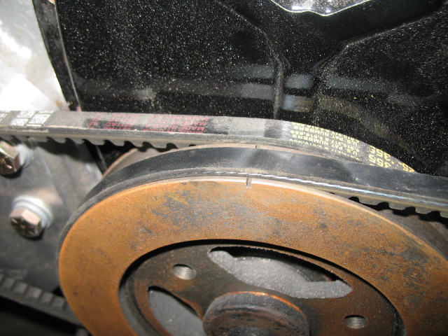
Posted by: wndsrfr Oct 11 2013, 07:53 AM
hooked my fuel to gas but she backfires and pops. I am sure I have my spark plug wires wrong.
is it safe to say that if the notch on the front pully is directly up, then where the rotor points is #1 ?? engine is a 307. #3932373
Not safe to say since you may have some mixed components such as timing cover vs. harmonic balancer. Here's a good thread to help you noodle it out:
http://www.chevytalk.org/fusionbb/showtopic.php?tid/198828/
Basically, get your firing order nailed first,
Then be sure you're on TDC #1 cylinder using a long phillips screwdriver through the spark plug hole & noting valves closed on that cylinder.
Note if the balancer timing mark aligns with the indicator on the timing cover.
You can then stab the dizzy to align #1 plug wire with rotor or just move wire#1 to align with whatever you have....your choice there. Then arrange the other wires in correct firing order--(note dizzy rotation direction!).
Then crank & twist dizzy by hand to fire her up.
After that works, figure out where the timing mark indicator needs to be or make a new mark on the harmonic balancer pulley...
Others may have a simpler procedure or point out what I've left out....
Posted by: jimkelly Oct 11 2013, 08:22 AM
firing order seems to be 18436572
but finding tdc is gonna be my challenge it seems
guess I got to pull a valve cover off first,and all spark plugs
thanks
Attached image(s)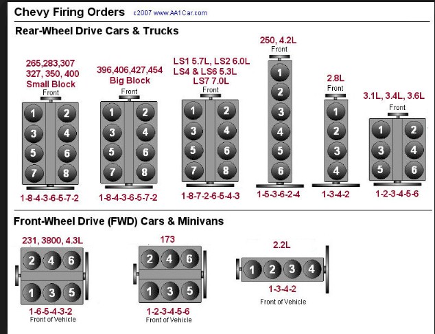
Posted by: DBCooper Oct 11 2013, 09:51 AM
or is this round mark at top of flywheel the tdc mark, indicating #1?
Almost certainly not. That't just a balancing hole, drilled randomly wherever in the flywheel they need to get it in balance, nothing to do with TDC. You need to pull a plug and valve cover to see if there's a mark there that lines up once you know you're at TDC.
You can buy an old school timing indicator tab for a couple of bucks at any auto parts store to put on a bolt near the front pulley. Just put a paint spot on the pulley when it lines up with zero on the indicator at TDC, then afterwards you can use a light to time the car more easily. Or use a variable metered light so you don't need to access the pulley.
Posted by: jimkelly Oct 11 2013, 10:36 AM
thanks guys, you've given me good guidance. dtf. no way can I rotate the engine by turning a wheel, too stiff. pushing the car while in gear is hell too. and the bolt holding the front pulling in place seems stripped. this is not gonna be fun : (
well, I had all plugs out and valve covers off. I "ROLLED" it forward and backwards and thought I had #1 cylinder on compression stroke, from seeing intake valve engage and then settle out and piston seemed to be at top of stroke. at first she just cranked over, so I added some fuel directly into the carb and then she4 spat out the carb and back fired thru exhaust. not much change.
looks like I need a new tool. the only problem is I don't have a smooth way to turn engine. psi and vaccum tool.
https://www.youtube.com/watch?v=u2sA-q7_FtQ
Attached image(s)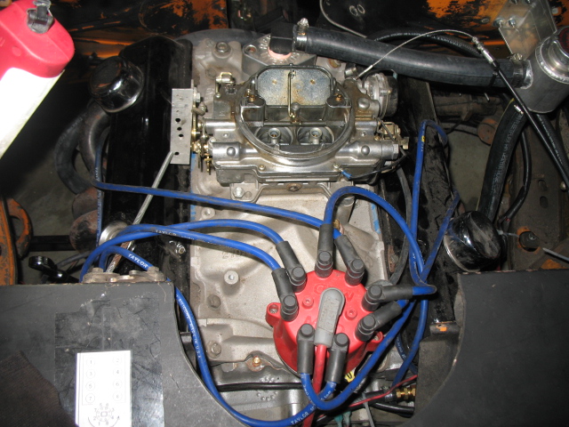
Posted by: tooms351 Oct 11 2013, 04:40 PM
Run a wire with allegator clips from starter selenoid to hot side of battery, but just tap battery to turn engine over. Put your finger over #1 spark plug hole to determine compression stroke, good luck!!!
Posted by: DBCooper Oct 11 2013, 04:42 PM
It looks like the number 1 wire goes up to the left front of the engine, to number one cylinder, good. But the next in order, number 8, the wire looks like it's going up to the right front of the engine, cylinder number 2, not to 8 in the rear. Your plug wires are really long, so they may be making a curve back, but it's odd. Maybe if you could just numbers on the photograph by each of the distributor cap's posts, according to what cylinder the wire's going to, it would clarify that.
Posted by: jimkelly Oct 11 2013, 05:24 PM
all the images i found have cylinders
1-2
3-4
5-6
7-8
distributor
I really think it is ready to run, but I am f-in something up
holy shit - do I have them completely backwards ????????????
the frist graphic I found was correct (ABOVE), but I taped a different graphic to my car because it was less clutterd but I did not notice it had the rotation different/wrong.
I just removed the graphics with the incorrect rotation from this post.
Posted by: jimkelly Oct 11 2013, 05:52 PM
I basically have the with my console - but will try with finger checking for pressure.
Run a wire with allegator clips from starter selenoid to hot side of battery, but just tap battery to turn engine over. Put your finger over #1 spark plug hole to determine compression stroke, good luck!!!
Posted by: jimkelly Oct 11 2013, 06:09 PM
db I could kiss you, right on the mouth. GREAT eye, and I mean GREAT!
the graphic I had taped to my trunk was backwards rotation
I swapped all my wires from cc to cw and she fired right up  and ran.
geez - 
1st video
https://www.youtube.com/watch?v=4vzjhXrokQQ
2nd video
https://www.youtube.com/watch?v=_iVB2-7rW8g
Posted by: Chris H. Oct 12 2013, 12:02 PM
db I could kiss you, right on the mouth.
Note to self, DO NOT HELP JIM WITH ANYTHING


Just kidding Jim, she sounds great man. It's a huge relief when it actually runs isn't it?
Posted by: jimkelly Oct 14 2013, 08:55 AM
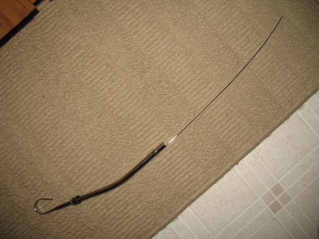
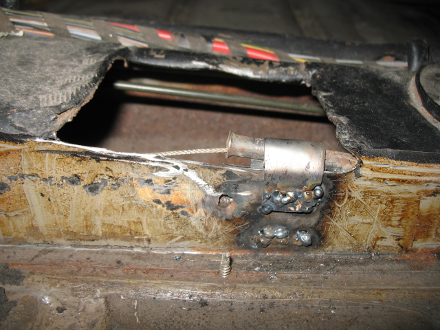
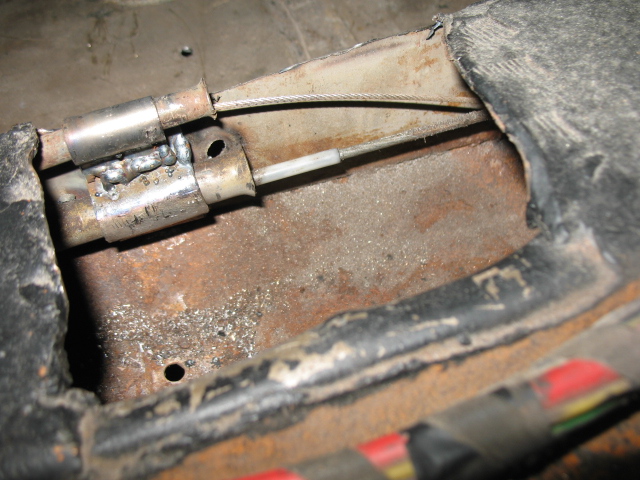
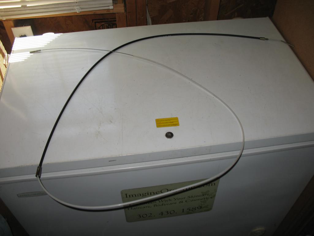
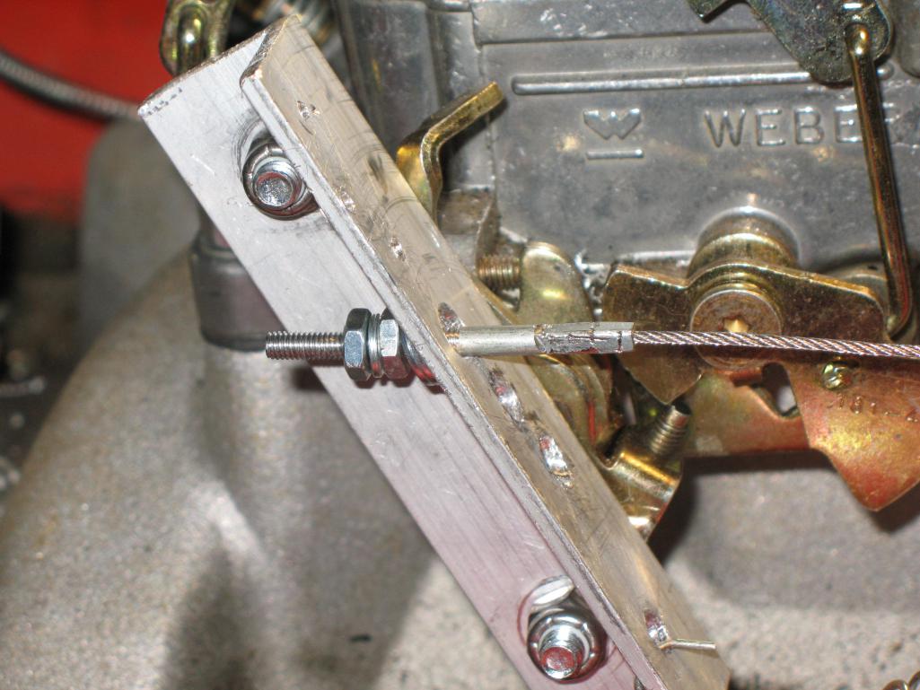
attached my throttle bracket and throttle cable, all looked good till I pressed the peddle, and snap. I got an email into terry cable to replace the one that is in my car.
119.5" total, 58" sheathing.
I do need need to drill one more hole in my throttle bracket and get the perfect spring.
and one of my spark plug wires is now too short to fit on any cylinder, need to get one medium length wire for #3.
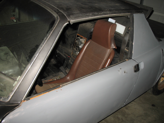
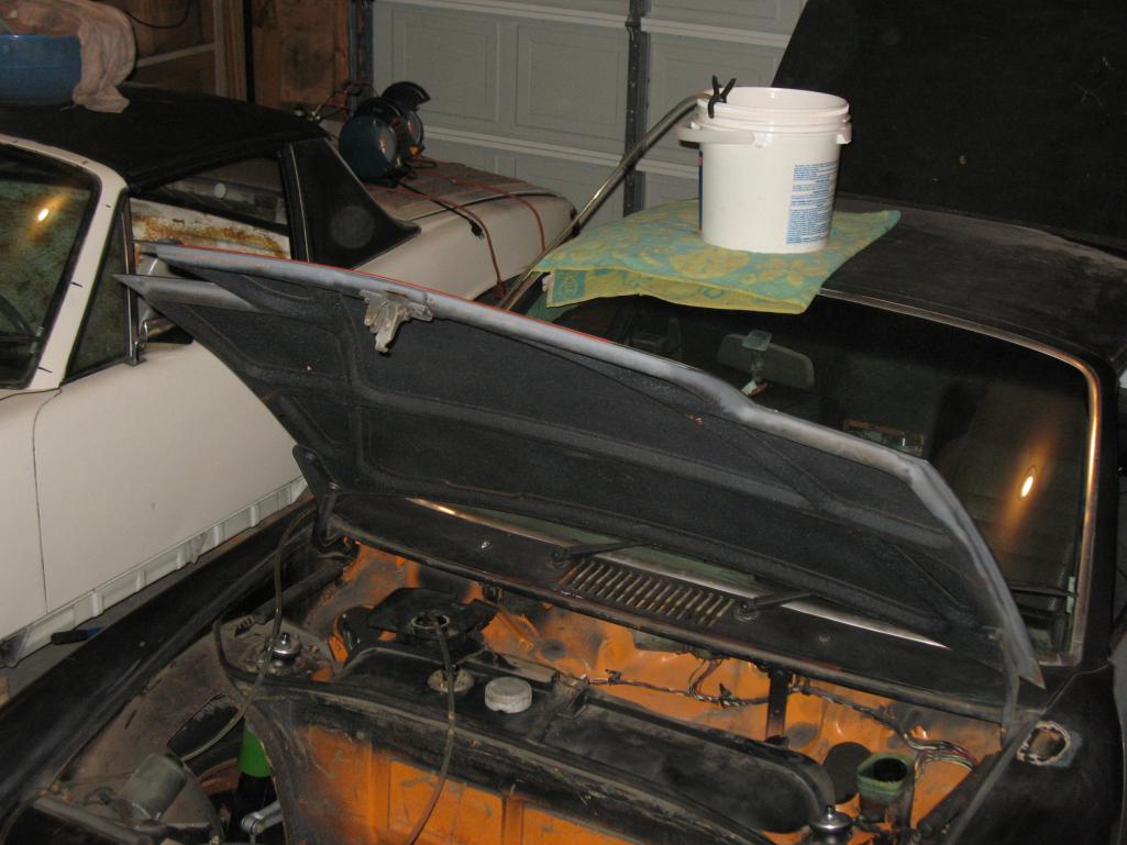
and all early door, door glass, removed from my fair weather car.
"less weight, more speed"
PS: chris h , I like your avatar : )
Attached thumbnail(s)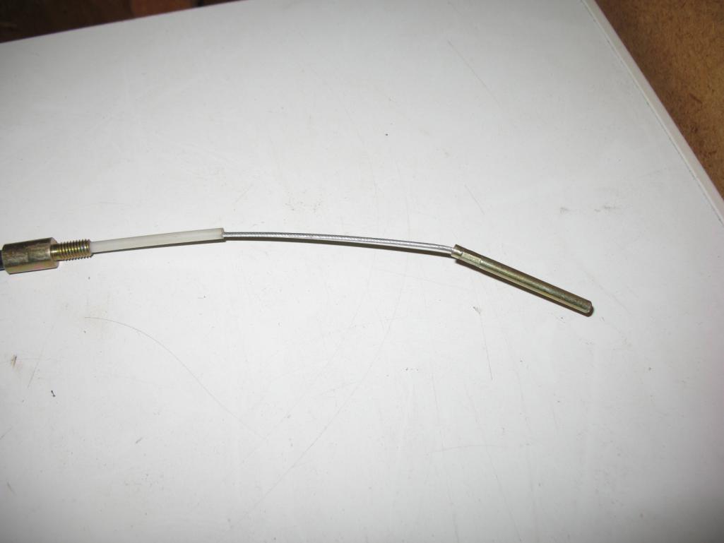
Attached image(s)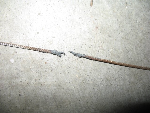
Posted by: jimkelly Oct 16 2013, 02:10 PM
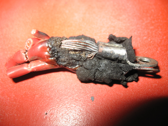
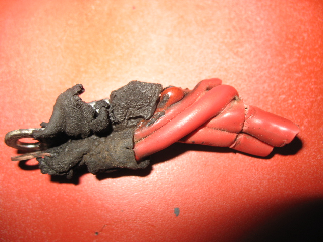
set back. fuse box was in contact with block and started a fire. not too bad luckily.
here is a past thread on this main topic.
http://www.914world.com/bbs2/index.php?showtopic=185880&hl=
having a quickly available battery quick disconnect makes more sense than ever.
better this happened with car in garage than 100 miles from home.
how do I splice these 4 RED wires together, properly?
Attached thumbnail(s)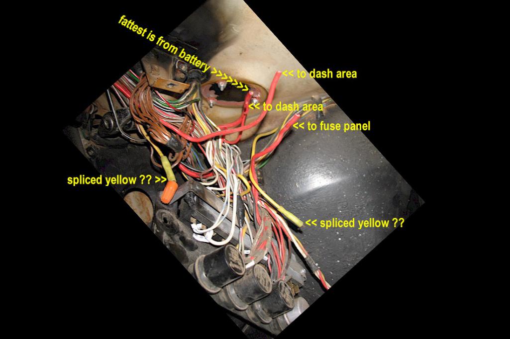
Attached image(s)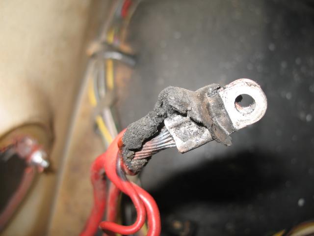
Posted by: Chris H. Oct 16 2013, 06:35 PM
Whew you dodged a bullet on that one Jim. Check Jeff Bowlsby's site for direction on the wiring. It's all there. My initial reaction is that the red ones can be connected to the battery directly but that may not be the case. You may already be planning this but pull that harness section and check all the wires in the general area really well. They get HOT and the insulation can separate even if they aren't charred. Give em all a good pull and twist. We want smoke coming out of the tires, NOT the engine bay.
edit: btw don't feel bad man, it happens. I had a wire swapped on mine too.
Plus...you got to say BIG CRIMP BUTT SPLICE in the next post!!! 
Posted by: jimkelly Oct 16 2013, 06:49 PM
I neglected the first rule - disconnect battery when working on electrical.
and did not benefit from those with early cars that experienced the same issue before me.
lesson learned.
I will definitely look over my wires, I see at three that need to be sectioned.
also, I need to find a big crimp butt splice that can accommodate the main hot from battery on one side and the 3 smaller wires on the other. (pic)
and hopefully my crimper will suffice, it does down to 10 gage.
I have some red, blue and yellow, insulated connectors, but even yellow is not large enough for the hot from battery. I think I need 8 awg.
Attached image(s)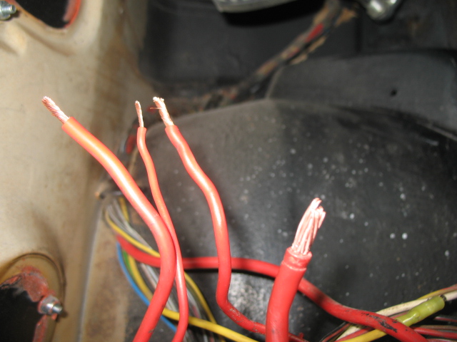
Posted by: jimkelly Oct 18 2013, 04:02 PM
I thought I may have fried my coil or dist but thank god I did not.
picked up a battery charger today at advanceauto $60 new, charged battery, and she started right up : )
like a dummy I had pushed the fuel line so far into the gas can that it wound up not being in fuel, and would not start, thus drained battery, and needed charger 
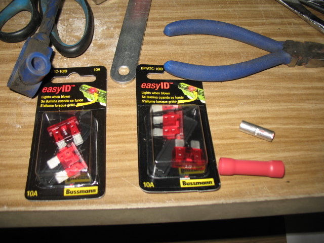
ok - back to repairing fried wires near the fuse box and need to add coolant to the cooling system. picked up some smart fuses and some 8 gage butt connectors.
lots of pics for those of you less mechanically inclined than me, but my guees is there are none : )
got some easy id fuses but they are 10amp, advance did not have 7.5, but later I found some 7.5 amp fuses on ebay and ordered a few.
Attached image(s)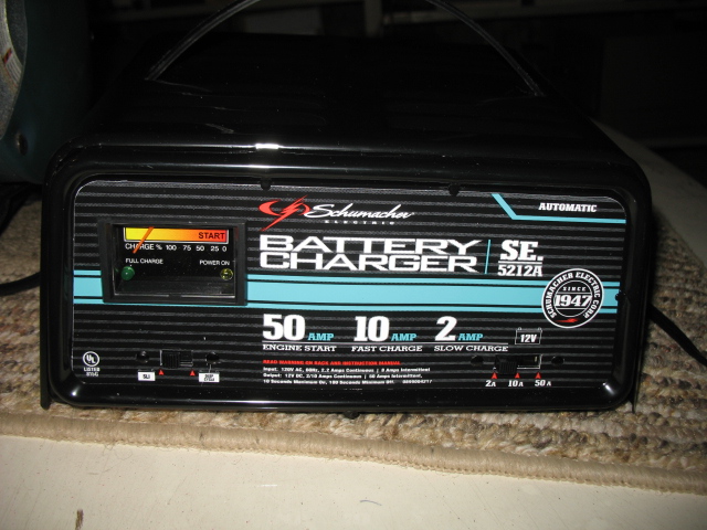
Posted by: bulitt Oct 18 2013, 04:22 PM
I neglected the first rule - disconnect battery when working on electrical.
and did not benefit from those with early cars that experienced the same issue before me.
lesson learned.
I will definitely look over my wires, I see at three that need to be sectioned.
also, I need to find a big crimp butt splice that can accommodate the main hot from battery on one side and the 3 smaller wires on the other. (pic)
and hopefully my crimper will suffice, it does down to 10 gage.
I have some red, blue and yellow, insulated connectors, but even yellow is not large enough for the hot from battery. I think I need 8 awg.
Jim try one of these- 5$ from best buy-
http://www.parts-express.com/pe/showdetl.cfm?partnumber=265-800
Posted by: jimkelly Oct 18 2013, 04:28 PM
price is right.
once this Bacardi wears off, I can give your suggestion some real thought
Attached thumbnail(s)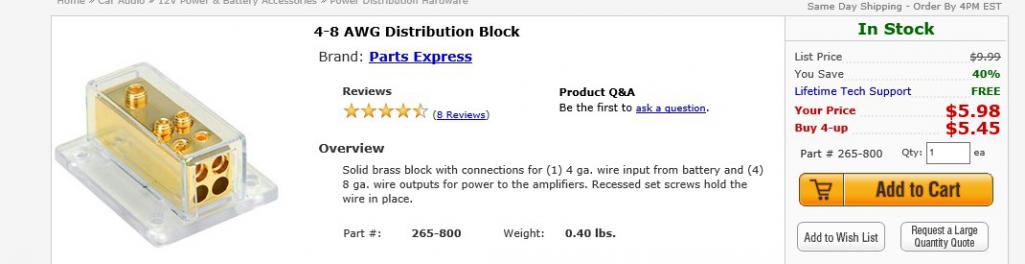
Attached image(s)
Posted by: jimkelly Oct 21 2013, 01:32 PM
yesterday...
filled cooling system with water, splashed a little everywhere.
temps started to climb high so I shut engine off.
I saw water bubbling on the manifolds, so I started to think I had some leaks.
later in the day I added some more water and she ran dry for about 5 minutes and the fans kept temps at about 160-170. can't remember if I have an thermostat installed or not.
today...
added a gallon or so of antifreeze as it has just started getting cold in DE.
I ran it a little longer today, all looks good with cooling.
got to...
order a new throttle cable from terry cables and install it
install the fuel tank, fuel line, and fuel pump
repair some wires under dash and reinstall fuse box
run some fused power to radiator fans
see if my ignition switch is working or not
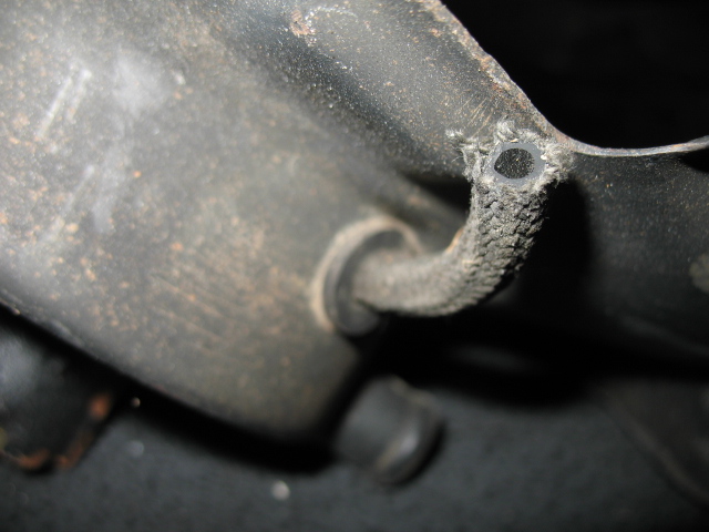
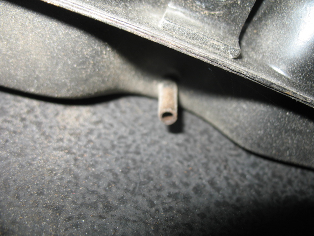
lastly, since I owned this car, I am pretty sure these yellow wires were never connected but must have been at one time. I don't understand what this yellow wire that goes thru tunnel is supposed to do. seems it is a starter wire?
fuel line in - the front grommet wasn't too hard to get in once I lubed it with soap - and I can see my fuel pump's pos and neg wires.
sad note: my son's parakett - Saphire - about 8 years old, passed away the other day, he came home from school to bury him.
Attached image(s)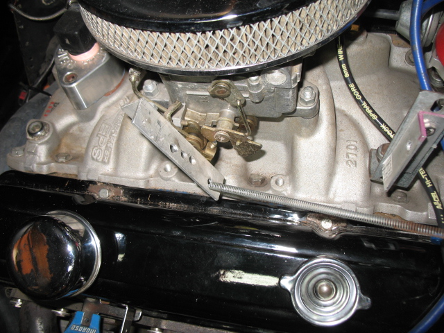

Posted by: jimkelly Oct 24 2013, 11:06 AM
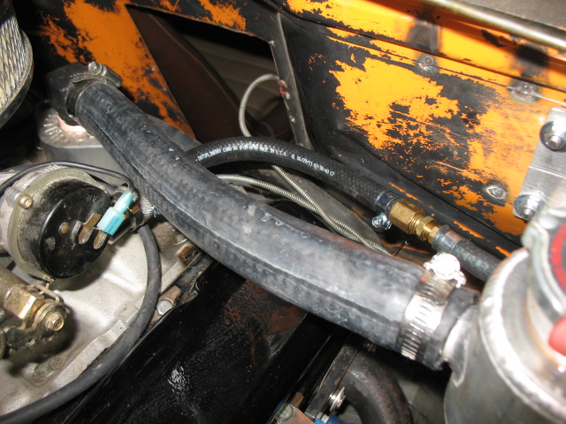
plumbed to carb from firewall, pump and filter.
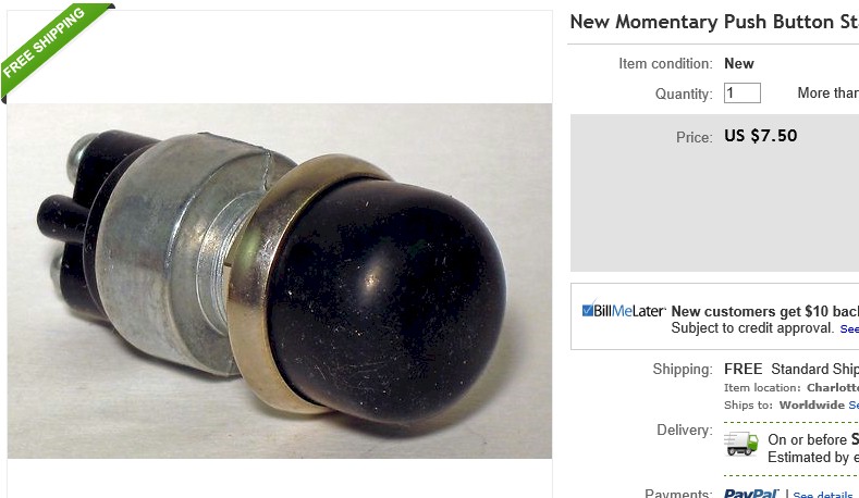
note to self: get a grommet or bushing onto the fuel line where it enters the firewall. and need a ring connector to replace the mechanical lug on the pos + battery terminal.
I am pretty sure I will install a momentary switch but more robust one than I had before, vs replacing the ignition switch, at least for now.
next up - install fuel tank.
Attached image(s)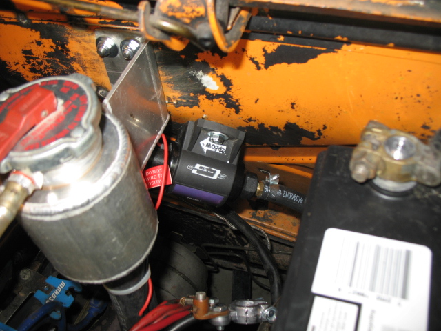
Posted by: jimkelly Oct 24 2013, 03:13 PM
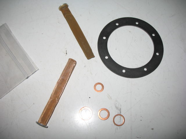
next to install fuel tank and plug the return line.
I need to remember why I ordered 4 metal gaskets, when I only need two. that I can see?
ok - I see how the rubber blocks sit on each side of the tank. I was thinking of setting the tank and doing the fuel lines from the bottom but I think I will go with a long line and hook up before tank install.
Attached image(s)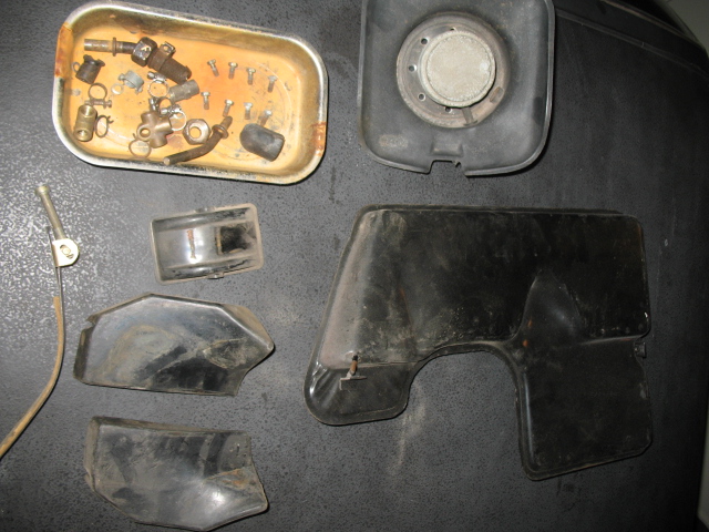
Posted by: jimkelly Oct 25 2013, 01:31 PM
got my fuel tank in and fuel pump wired. I need to locate my fuel sending unit which has a different plug than a late model it seems.
got my 7.5amp fuses today and my headlights low and high beams work, always did before.
but I have a new electrical gremlin. I assume it has something to do with me oppsing a wire or two, when installing the engman fuse panel?
the new one is this, when I pull the hazard switch, my fuel pump comes on?
my fuel pump also comes on as it should when I turn the ignition key, with hazards off.
I ended up cutting away some sheet metal and shortening the fuel line under stank, so I could make last fuel line connection to tunnel fuel line from under the car.
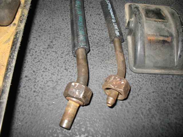
as was suggested in another thread, I should have made a round disk out of rubber and used it and a washer and the normal nut to cap off the return line.
also it appears that the later cars used the same diameter nipples for both, where as my 1972 car had a larger line 3/8 to engine and 5/16 return.
for me, going straight from tank to tunnel line, I think a tighter curve on the nipples would have been much better, on both, even the capped off return.
Attached image(s)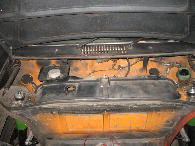
Posted by: rhodyguy Oct 26 2013, 07:48 AM
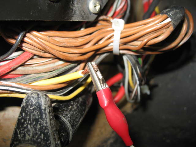
did you use the jumper wire from the engine relay board to the nearby ground stud to provide a ground for the pump?
Posted by: jimkelly Oct 26 2013, 07:52 AM
yes - like this.
did you use the jumper wire from the engine relay board to the nearby ground stud to provide a ground for the pump?
Posted by: rhodyguy Oct 26 2013, 07:55 AM
the only way to go and still utilize the stock circuitry.
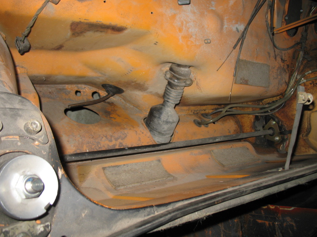
Posted by: jimkelly Oct 27 2013, 07:16 AM
I could have sworn my car started from key with this fat yellow wire disconnected, but it was driving me crazy, so I just tested the yellow wire and it does produce power when key is fully turned. so what must have happened is butt connection came apart and I did not put 2 and 2 together. be thankful you have more functioning brain cells than i do.
I still have 2 gremlins, drivers side parking light does not blink when headlights are on and fuel pump comes on when I pull hazard switch. but at least I won't have to wire up a rigged momentary starter switch.
obviously I am using a headlight to do my electrical circuit testing.
Attached image(s)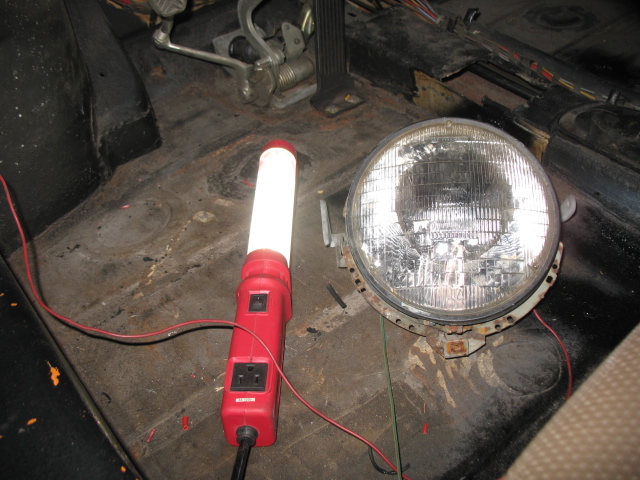
Posted by: Spoke Oct 27 2013, 08:01 AM
I still have 2 gremlins, drivers side parking light does not blink when headlights are on and fuel pump comes on when I pull hazard switch. but at least I won't have to wire up a rigged momentary starter switch.
obviously I am using a headlight to do my electrical circuit testing.
Is it the driver's front turn signal that doesn't blink with lights on? Are both filaments on at this time? When blinking, do both filaments blink? The ground for the lamp base may not be grounded or the bulb isn't making good contact with the housing.
For the fuel pump, I would start by tracing all wires to/from the pump to look for issues.
Posted by: jimkelly Oct 27 2013, 08:29 AM
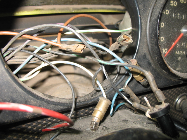
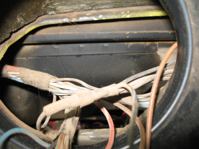
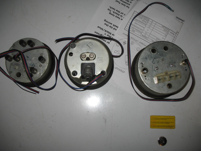
now I am seeing problems everywhere. I pulled a tach out of my 1975 and pulled the speedo out of my v8 and all of a sudden I noticed my drivers side parking light on, I thought I shorted it on, but later realized I have pushed the turn signal stalk downward : ) whew, don't need any more gremlins.
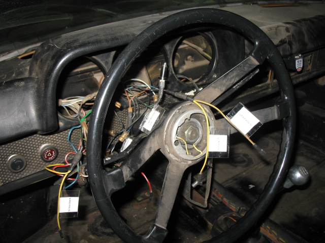
here are some pics of the wires behind the gauges,
the pics with wires attached to tach are of my 1975 car, the more dusty ones are of my 1972 v8.
for my v8, I plan to use the tach only for its directional indicators. rarely will I be bumping against redline or needed to monitor redline. street car.
Attached image(s)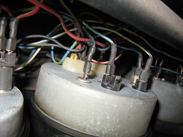

Posted by: jimkelly Oct 27 2013, 08:36 AM
I will check. I assume you mean both filaments in the parking light?
I assume the problem may not be in the wiring at the parking light because it flashes when hazard switch is pulled. though my fuel pump comes on too.
jim
--
I still have 2 gremlins, drivers side parking light does not blink when headlights are on and fuel pump comes on when I pull hazard switch. but at least I won't have to wire up a rigged momentary starter switch.
obviously I am using a headlight to do my electrical circuit testing.
Is it the driver's front turn signal that doesn't blink with lights on? Are both filaments on at this time? When blinking, do both filaments blink? The ground for the lamp base may not be grounded or the bulb isn't making good contact with the housing.
For the fuel pump, I would start by tracing all wires to/from the pump to look for issues.
Posted by: jimkelly Oct 27 2013, 09:11 AM
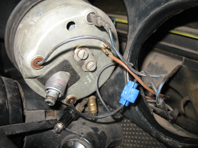
spoke - just tested your directionals rewiring - works great : ) but I need to get an old tach with two green lenses.
UPDATE .. parking light/directional issue resolved - bad bulb and I had the two non ground wires reversed - DS directional working now
next up - last electrical gremlin - fuel pump/hazard switch issue.
also - trying to determine what this white/green wire is for behind my tach area. UPDATE: tom advised me, in a separate thread, that this WHITE/GREEN wire powers a bulb in the speedo when the parking lights are on. I must have jumped a nearby wire to get power in the past.
http://www.914world.com/bbs2/index.php?act=ST&f=2&t=223447&st=0#entry1947448
it sure sucks when the DAPO is ME
Attached image(s)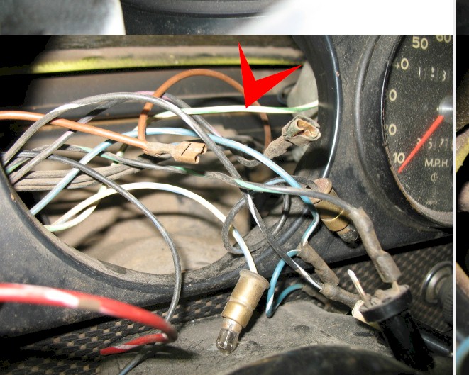
Posted by: jimkelly Oct 27 2013, 11:21 AM
well - later tach won't do.
it only has one green dot for both left and right directionals : (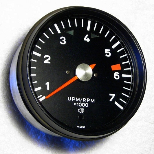
Attached image(s)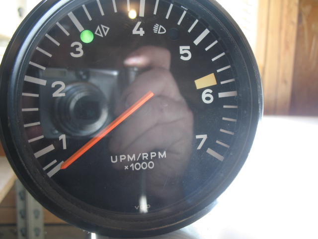
Posted by: Spoke Oct 27 2013, 02:53 PM
Yeah, I didn't like the later tach because of the single turn signal indicator. So I took the tach mechanism out of the later tach and put it in the early tach can with the early tach faceplate. The only hard part about it is opening up the bezel.
Does your later tach have a glass or plastic window?
Posted by: jimkelly Oct 27 2013, 03:44 PM
pretty sure its plastic - but I will put it back in my 1975 and seek out a lowww budget early tach since I do not need the tach to work. just want dual directional indicators.
Posted by: kg6dxn Oct 27 2013, 08:26 PM
yes - like this.
As I ponder your symptoms... Do yourself a favor and get rid of the spiral wires. They look neato but create an electro-magnetic field and turn the wire into an inductor. Inductors oppose current flow.
You can use the same spiral wire to magnetize your screwdrivers. Slide the spiral over the screwdriver and tap both ends of the wire across a battery. Do it once, quickly and remove. You will see a spark. You only need to connect for less than one second.
You can also use this to shoot nails across the room or when connected to AC power, make you own prison tattoo machine...
Bottom line, the spiral wire creates a circuit that can and will create problems you don't need.
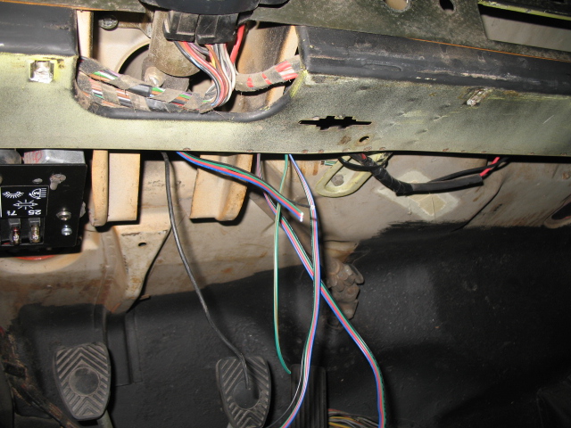
Posted by: jimkelly Nov 2 2013, 08:53 AM
been off on a tangent with - spoke, dave darling, r towle, conedodger, rhodyguy, halfmoon, rand, mepstein, jeff bowlsby,etc
had 3 issues, two remain, no wipers and no horn.
http://www.914world.com/bbs2/index.php?showtopic=223741
hooked up ignition to starter wire and reverse lights wire to trans.
Attached thumbnail(s)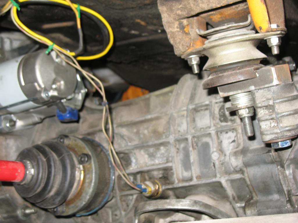
Posted by: jimkelly Nov 2 2013, 09:08 AM
ok - she started off the ign key and ran for some seconds but stalled out. seems it ran from the fuel in the bowl but is not getting fuel from the pump.
I think the pump needs to be lower in order to get fuel to it via gravity ???
i'll also check for a kink in the fuel line.
Attached image(s)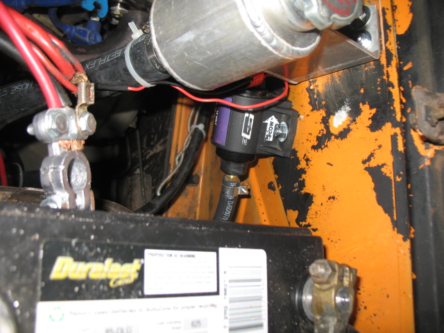
Posted by: kg6dxn Nov 2 2013, 09:36 AM
You should mount the fuel pump in the front of the car, down low. You will have vapor lock problems with it in the rear and mounted so high. It will be hard for the pump to prime mounted like that.
Posted by: rhodyguy Nov 2 2013, 11:46 AM
rotary pump? if you don't want to do the front put it on the lower fire wall, elevation near where the line exits for the tunnel. easy peasy to use the stock pump wiring. i had wondered about the eng comp location near the battery. fumes, heat, and sparks.
Posted by: jimkelly Nov 2 2013, 02:46 PM
I checked for a clog or other issue, gas all over the place, thought I had it working, but it ran for about 3 minutes and cut off again.
I had a similar pump when I was driving it before, lower mounted. but I do have a nice edlebrook pump and rethinking selling it, and installing it instead, but I'll need some 3/8 npt nipples. and it will allow me to eliminate the one in-line reducer I had to add because the pump I am running now has a 3/8 nipple on one side and 5/8 on the other. maybe I need more line pressure than the POS that I am currently using can provide. though I will look into mounting it lower either way, but I want to avoid upfront as just running the hose was a PIA. a more curved lower tank larger nipple would have been better.
what's funny is the engine was running fine with this pump when I had it feeding from a gas can in my trunk thus I do think its height in relation to the gas tank may be an issue.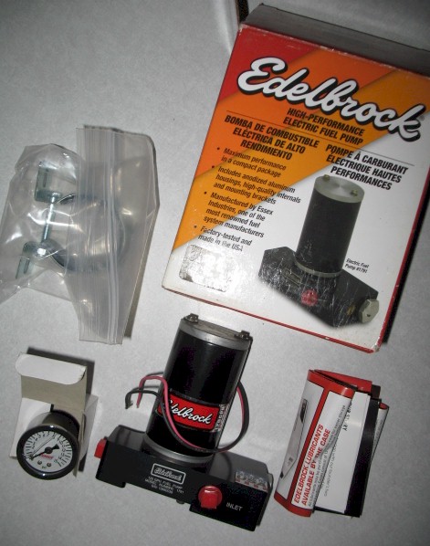
Posted by: bulitt Nov 2 2013, 07:47 PM
Obvious Question Jim- do you have gas in the tank?
Posted by: jimkelly Nov 3 2013, 06:29 AM
yes - about 3 gallons - and it spills out if I disconnect the hose in the engine bay.
good point though 
you know though, I do have the car on jack stands at the rear, (I did not when i first noticed the problem though) and maybe 3 gallons is not enough, even though I can see gas is higher than strainer, maybe the angle of the line is such that it is denying the pump the amount of gas it needs.
i'll put the car down before I do anything else.
Attached image(s)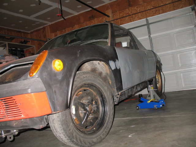
Posted by: jimkelly Nov 4 2013, 01:23 PM
dropped ground, but still no good.
put car back on jack stands and dropped pump on ground, she ran great.
probably a safety hazard driving with pump dragging on ground
I will mount pump on engine bar for now, as this is just lower than where the fuel line exits the firewall.
is this form-a-gasket stuff by permatex ok for sealing npt fittings to a fuel pump. fuel pump installation papers suggest a sealant. I ask because I think I am going to go ahead an install my edelbrock fuel pump after all.
Attached image(s)
Posted by: mittelmotor Nov 4 2013, 05:17 PM
Nice progress. I've heard the pumps are much better at "pushing" fuel than pulling it, hence the low mounting point for gravity feed to the pump. I put mine beneath the gas tank, without any sort of access hatch, so failure means pulling the tank. But fuel pumps are pretty reliable these days, so I figured what the heck!
Posted by: jimkelly Nov 4 2013, 07:28 PM
thanks. lots of pics for those few, that may be less capable than myself.
and my pump's manual does address - push fuel.
I could issues with driving DOWN steep roads ???
Attached image(s)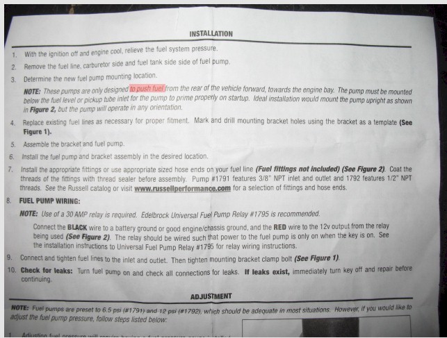
Posted by: Mike Bellis Nov 4 2013, 08:00 PM
The Permatex sealant is the best one I've ever used. I use it for all the pipe connections on diesel fuel systems. It is copper based and will never harden. Perfect for fuel connections.
Posted by: DBCooper Nov 5 2013, 08:53 AM
I've used that stuff since I was a kid. Never had any reason to change, so I was curious to see what answers you got, since I've never really had anything else to compare it to. I'd just add don't use too much on threads, you aren't gluing anything together, you're just putting in enough to fill gaps when it tightens. A thin smear is plenty.
Mike, you changed your name. And I can pronounce it now.
Posted by: jimkelly Nov 5 2013, 01:15 PM
thanks guys for the comments on the permatex product!
just returned from napa where I got a small tube of permatex form-a-gasket sealant, and from ace where I got some hardware to mount my edelbrock pump. waiting on a delivery from ebay of some heat shrink 1/8 ID and 1/4 ID as I ran completely out. this time I got 3:1 ratio heat shrink with adhesive center, I think the stuff I just ran out of was 2:1 and did not have a juicy adhesive center either.
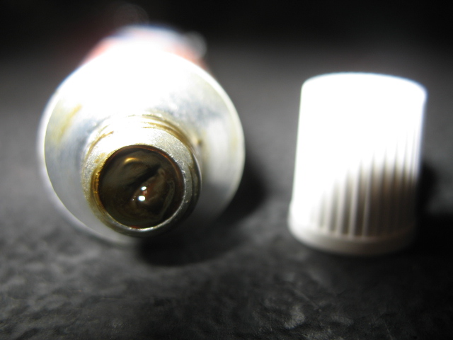
I should have been expecting this stuff to be DARK color, keep it away from your wife's kitchen towels : )
two guys mostly work at my local napa, a nice guy about 55, and a young tobacco chewing, slow moving, could give a shit, punk. yesterday I got the older guy and I asked him about the stuff vs permatex's thread sealant. he said he used Teflon tape for years with no problems. just like internet threads say when you search what to use on npt threads with fuel. the form-a gasket was a buck cheaper, so I went with it.
Attached image(s)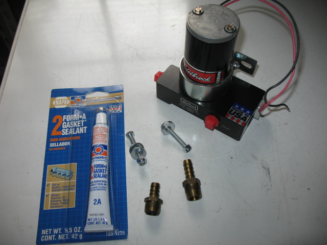
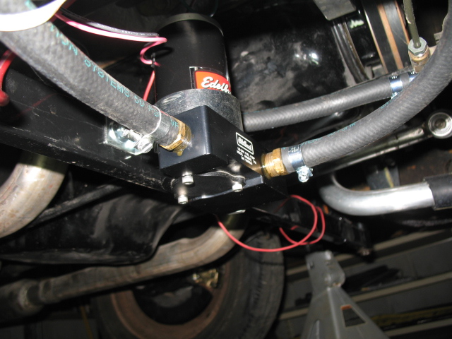
Posted by: jimkelly Nov 7 2013, 11:26 AM
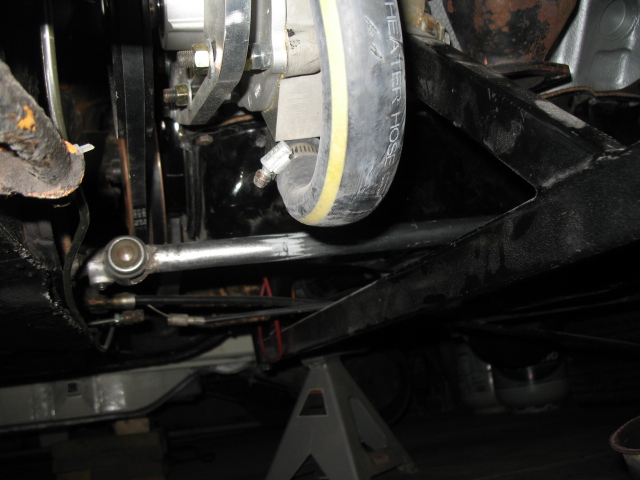
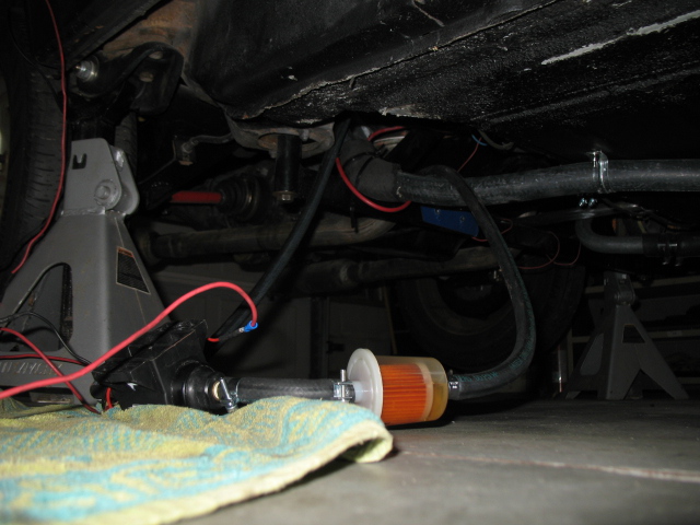
pump in but will probably relocate fuel filter further down, away from header, later on.
is it ok for fuel filter to be horizontal, like I have it, or should it be vertical?
the fuel pump inlet is a good 2+ inches below the fuel line coming out of the firewall but the pump bottom is 1 inch below the engine bar, I will probably need to raise it to at least flush with bottom of engine bar.
Attached image(s)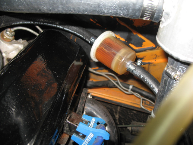
Posted by: rhodyguy Nov 7 2013, 11:28 AM
filter pior to the pump?
Posted by: jimkelly Nov 7 2013, 11:36 AM
its after pump. when I had pump higher, I had it before pump.
I could put before if it is ok to have horizontal, as I have it now, ironically.
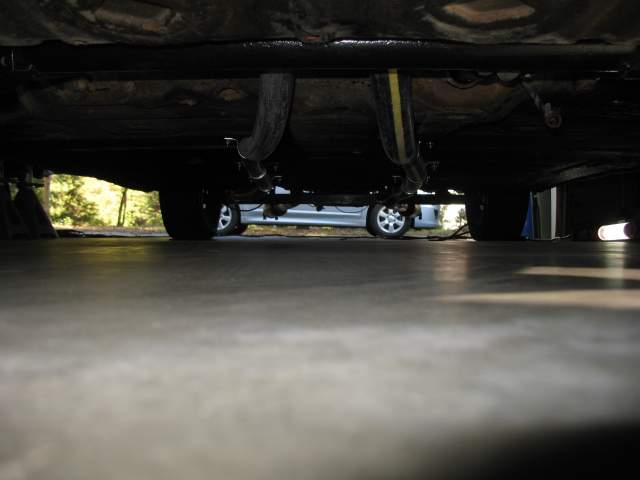
and how I plan to change up my exhaust, to get it quieter and to get it higher off the ground at the tailpipe, too noisey for neighbors and I scrap my tail pipes too much.
gonna keep it dual, for the annoying drone, and it may be helpful when I get it tuned as both sides of engine can be checked independently with a sniffer.
Attached thumbnail(s)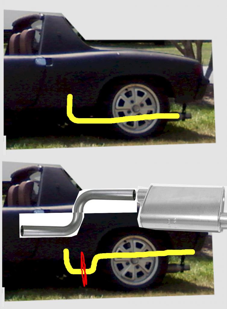
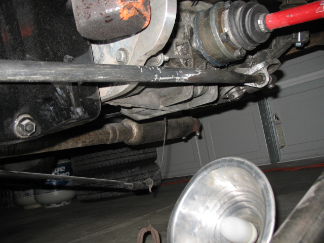
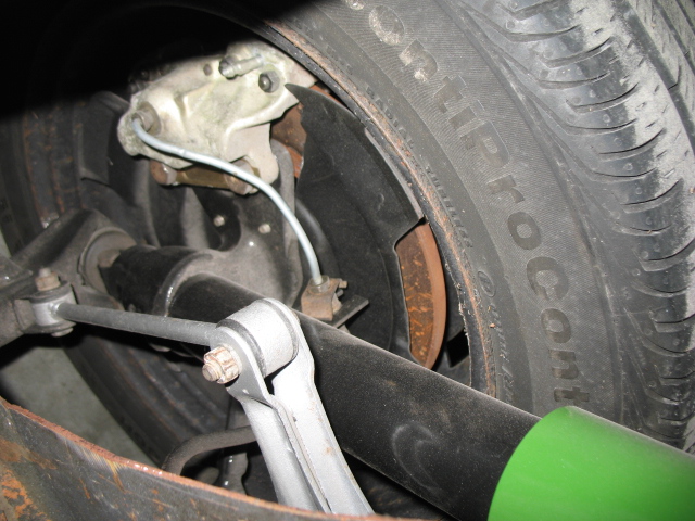
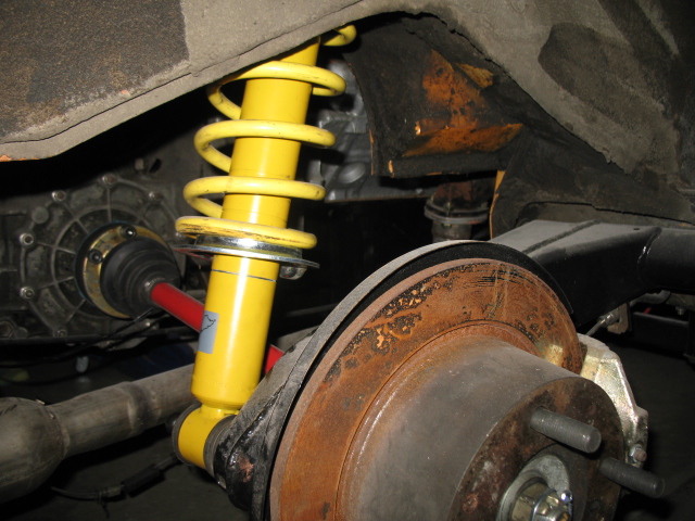
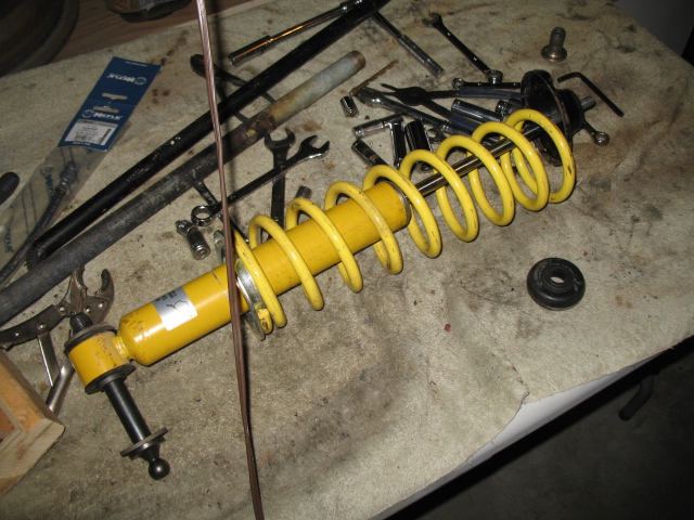
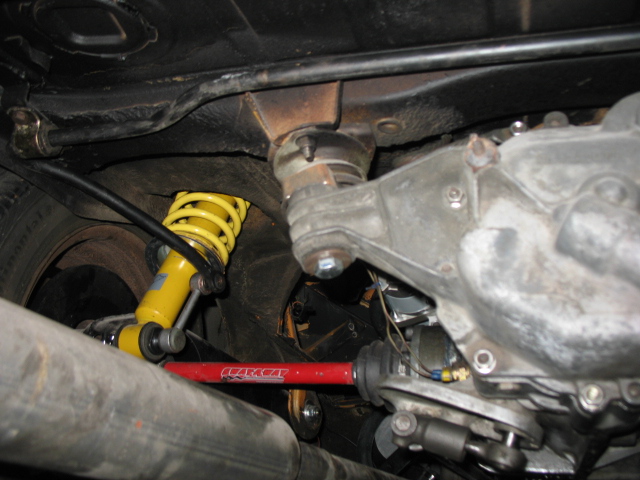
Posted by: jimkelly Nov 8 2013, 12:18 PM
i had temporarily removed my rear sway bar so I can mess with my rear shocks.
a c clamp got the bushings back on the bar with ease but it took a scissor jack between trans and shock bolt to get them back together, with ease also.
Attached image(s)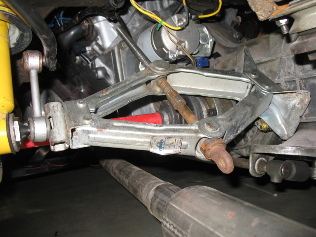
Posted by: Mike Bellis Nov 8 2013, 08:29 PM
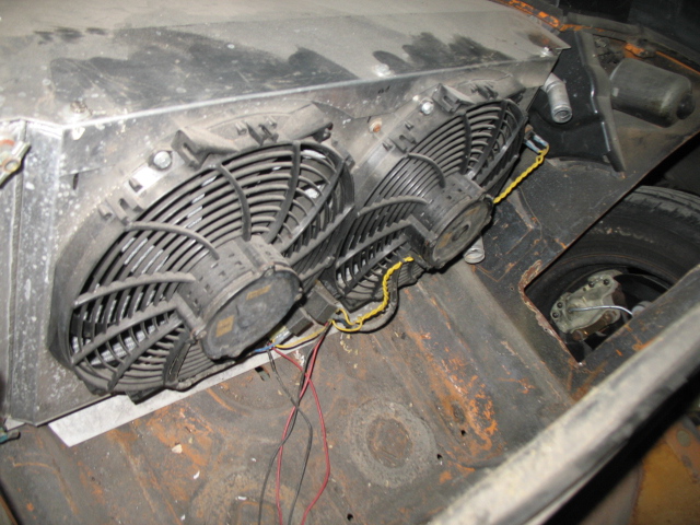
From the pics, that looks like a very bad pump location. I have scraped my engine bar on various bumps and humps. I also scrape my radiator hoses ALL THE TIME. I make it a point to un-crush the straps every couple months...
I also think it should be located up front to avoid vapor lock. I run mine in the front trunk for easy access. If you intend to keep it back there, you should change to a return fuel regulator system to mitigate vapor lock.
Posted by: jimkelly Nov 8 2013, 08:40 PM
I too have smashed my share of hose straps but did not know that some have bottomed out their engine bars, thought the renegade bar I have now sits closer to the road than my old bar did.
my pump is definitely too low and I will reevaluate mounting it upfront. I will need power for it and power for my radiator fans too.
thanks for the input!
Posted by: cwpeden Nov 8 2013, 09:06 PM
Is that sway bar upside down? See pic near the bottom of this post for the right way:
http://www.914world.com/bbs2/index.php?s=&showtopic=123957&view=findpost&p=1829158
Posted by: jimkelly Nov 8 2013, 09:30 PM
I think you are right
I looked for pics and AA;s diagrams before I committed to the orientation but obviously looked at them wrong. i'll flip it tomorrow. why is it when there is a 50/50 chance of getting it wrong, I do
Attached image(s)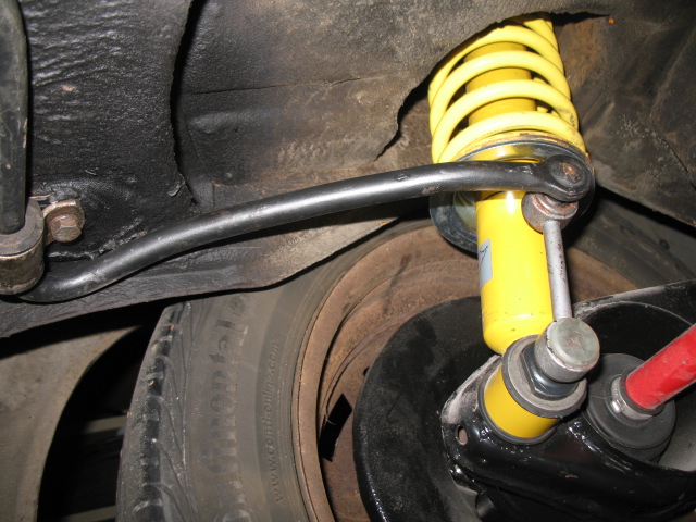
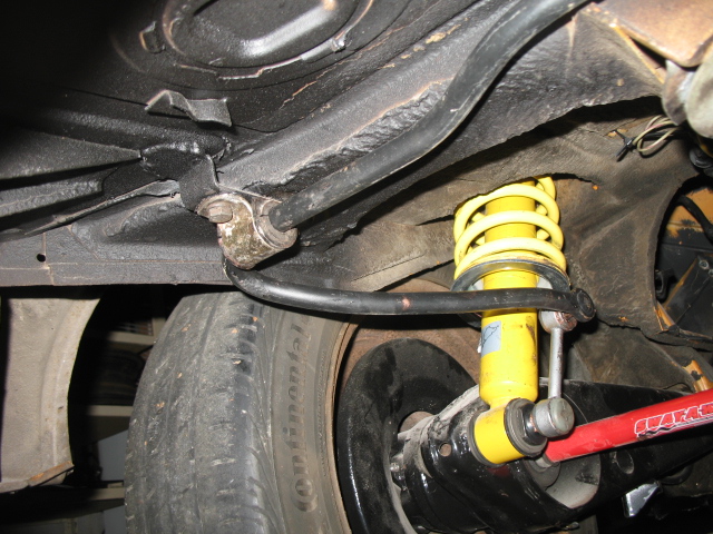
Posted by: jimkelly Nov 8 2013, 10:04 PM
why put off till tomorrow what you can to at 11pm?
corrected.
thanks again!
Attached image(s)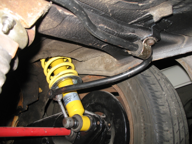
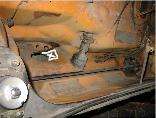
Posted by: jimkelly Nov 9 2013, 10:09 AM
I guess peddle board mounts to tunnel via fixed not on access plate?
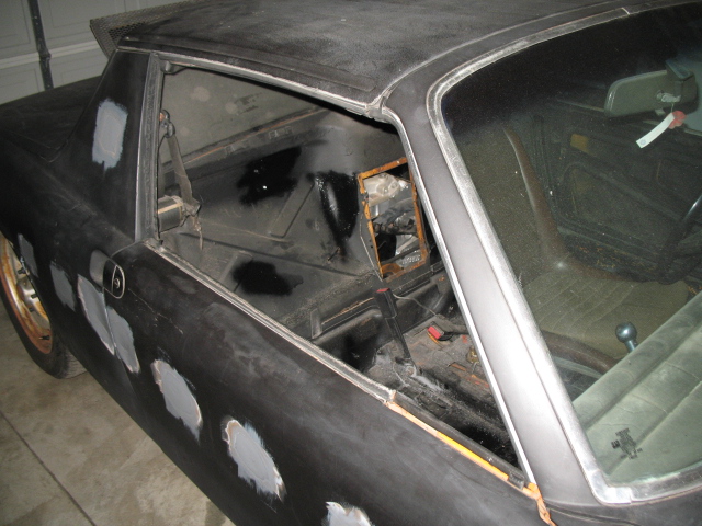
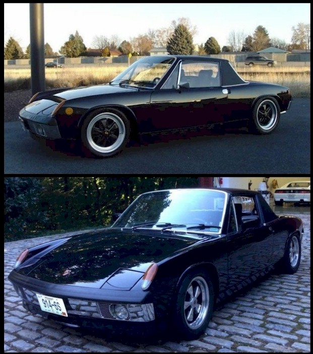
and 2 narrow body gloss black cars
Attached image(s)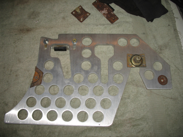
Posted by: jimkelly Nov 16 2013, 08:42 PM
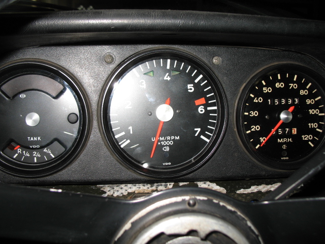
just rcvd a full set of led illuminated gauges from timothy_nd28.
http://www.914world.com/bbs2/index.php?showtopic=217100
they are going to be sweet.
I can now also implement spoke's directional indicator light improvement that will have them both flash properly.
poor dash lighting, wacky directional indicator lights, and a sloppy drivers door mirror were some pet peeves I had with my car.
more pics and video to come once gages are installed.
Attached image(s)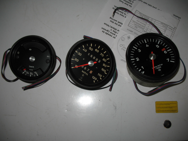
Posted by: timothy_nd28 Nov 16 2013, 10:28 PM
Can't wait to see this modified tach work with your V8, fingers crossed. ![popcorn[1].gif](style_emoticons/default/popcorn[1].gif)
Posted by: jimkelly Nov 17 2013, 05:08 AM
here is a little graphic I came up with to prepare for install.
click on image to ENLARGE.
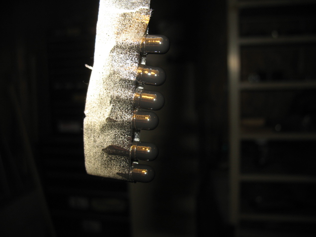
1- most incandescent bulbs get reinstalled. all BACK LIGHT incandescent bulbs get painted with black nail polish first. note that 3 BACK LIGHT incandescents can't get reinstalled because their sockets are being occupied by the RGBblk 4 wire ribbons, thus 3 incandescent bulbs will have to hang loose behind the gage cluster.
2- the indicator bulbs don't get painted black, as they are still needed.
ok, so it is now the afternoon, and I buttoned up my wiring. I now have a wire for my parking lights indicator, my high beam indicator, I made 3 sets of pictails to fed the box's purple and black wires, and I labeled my left and right directional indicators. I painted the back light bulbs with gloss black rustoleum I had laying around. I plan to pop the gages in tomorrow and get a video of them in action.
Attached thumbnail(s)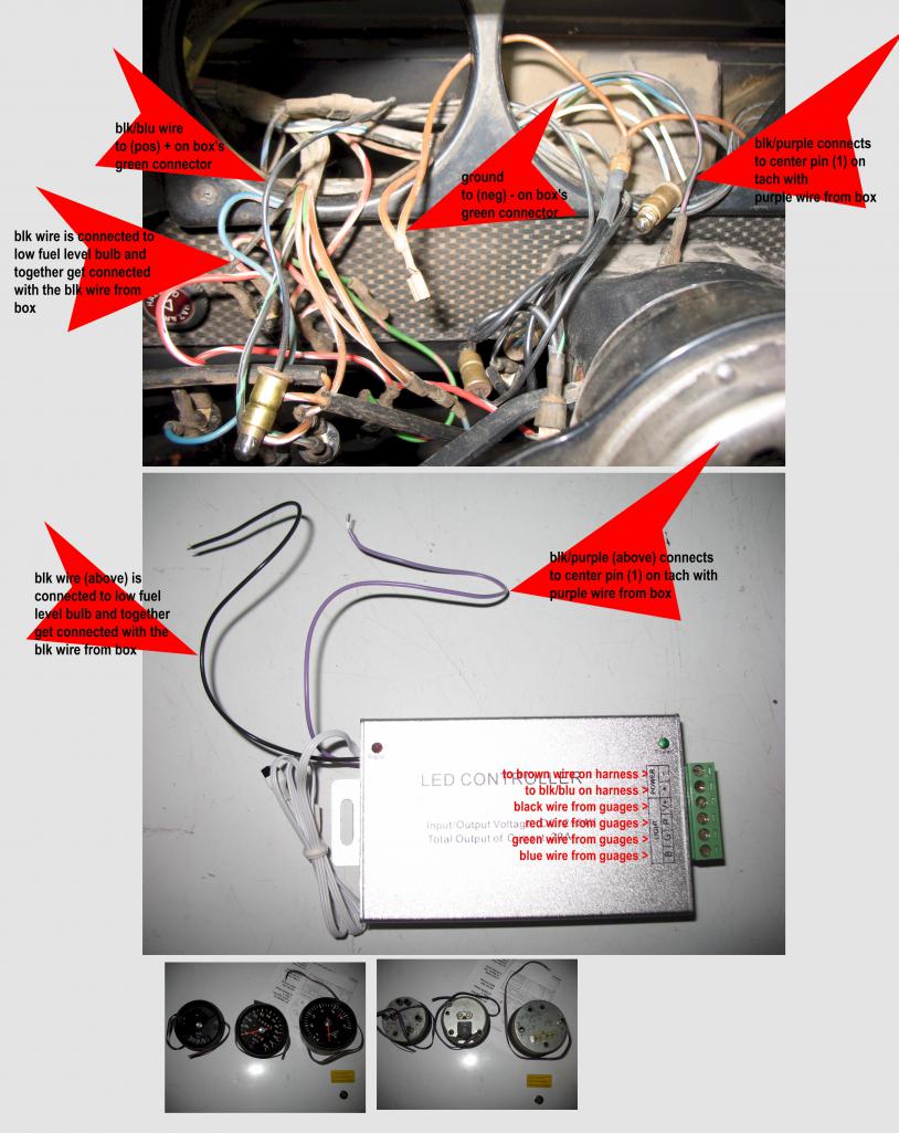
Attached image(s)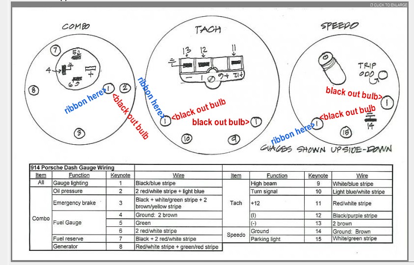
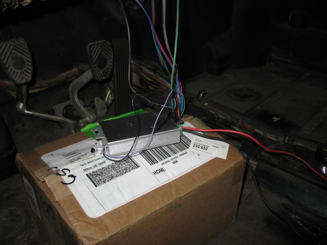
Posted by: jimkelly Nov 23 2013, 12:24 PM
got my lights from timothy in and wired for testing.
it is so nice to finally have every light in good working order, except for oil dummy light. need to hook up a sender for that.
and real nice to be able to retain my stock tach with the V8.
it is going to be great to be able to see my gauges at night in any color is want : )
for now, I have controller wire tied to just under the steering column. I need to give final position of it and routing of wires a little more thought.
http://www.914world.com/bbs2/index.php?showtopic=217100
video...
https://www.youtube.com/watch?v=cwDCp5jcSfI
Attached image(s)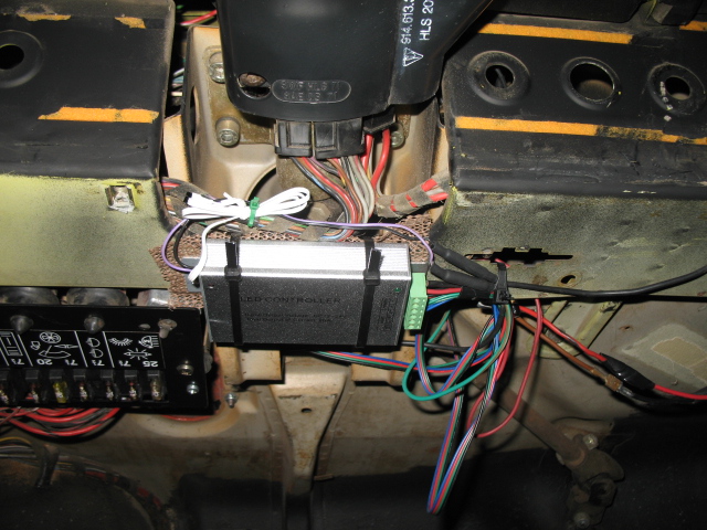
Posted by: jimkelly Dec 5 2013, 10:33 AM
a feature I forgot to check with my new gage lighting from tim.
high rpm warning set at 4000.
https://www.youtube.com/watch?v=h7-u_CQv0jo
Posted by: chads74 Dec 5 2013, 12:26 PM
I love how you did the gauge lights for your "shift light"
Posted by: messix Dec 5 2013, 12:32 PM
do the lights have to be on for the shilt light feature to work and is it noticeable during the day in daylight?
Posted by: saigon71 Dec 5 2013, 01:01 PM
Great looking gauge set up Jim.
I look forward to seeing this car in Hershey in the Spring.
Posted by: jimkelly Dec 5 2013, 01:32 PM
the shifter glowing is merely a result of reflection
my shift knob is solid polished aluminum and bought from http://nirvanamotorsports.blogspot.com/p/porsche-shift-knobs.html
Posted by: timothy_nd28 Dec 5 2013, 03:56 PM
Jim, it looks great. You can take this one step further though. By integrating a temp gauge to your combo gauge will not only look better, but that gauge becomes much brighter.
Also, the controller is set for red warn only at 4k RPM. There is also a yellow warn light that can be enabled if you wish.
Posted by: 76-914 Jan 21 2014, 10:38 AM
Thought I'd throw this back up front. Where are you on this? Are you a candidate for my "Slacker's" thread?
Powered by Invision Power Board (http://www.invisionboard.com)
© Invision Power Services (http://www.invisionpower.com)