Printable Version of Topic
Click here to view this topic in its original format
914World.com _ 914World Garage _ Water Cooled Question
Posted by: 76-914 Dec 6 2013, 11:18 AM
For my Suby 6 conversion I've installed a twin fan system (from a Dodge) on my radiator. One is single speed (3 wire) and the other is 2 speed (4 wire). Which one of these 2 fans comes on first? Do they both run at times? Will I use the 2nd speed of the 2 speed motor?
Posted by: mikesmith Dec 6 2013, 11:29 AM

For my Suby 6 conversion I've installed a twin fan system (from a Dodge) on my radiator. One is single speed (3 wire) and the other is 2 speed (4 wire). Which one of these 2 fans comes on first? Do they both run at times? Will I use the 2nd speed of the 2 speed motor?
It will depend on what you're using to drive the fans...
The Renegade SBC setup, for example, is either all off, or all on.
Posted by: 76-914 Dec 6 2013, 12:30 PM
I'm using the stock OEM Suby ECU.
Posted by: mikesmith Dec 6 2013, 02:40 PM
Based on a quick Google search, it looks like there are two fan control outputs from the Subaru ECU. One is marked "Only for A/C vehicles", so it's quite likely that it won't be switched unless the ECU thinks that the A/C is on.
To start with, I'd wire both fans to a suitably beefy relay and run both at full speed when the ECU asks. You could try to finesse it later (e.g. using a SPAL PWM controller with the ECU fan wire connected to the A/C input on the SPAL controller).
Posted by: BIGKAT_83 Dec 6 2013, 04:58 PM
I would turn the two speed on first at low speed and then when the temp increased switch it to high speed with the second fan.
On my car I turn on both fans at half speed at 190 degrees and if the temp gets to 200 degrees both fans go to full speed.
This is easy to do using 3 relays. Slow speed is the fans wired in series and then put them in parallel for full speed.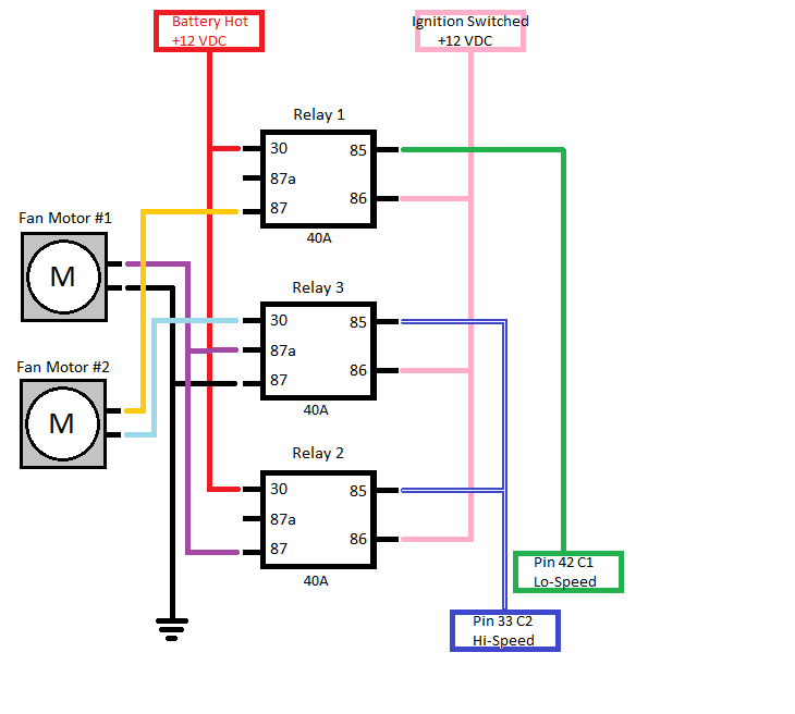
Posted by: mgp4591 Dec 6 2013, 06:28 PM
I would turn the two speed on first at low speed and then when the temp increased switch it to high speed with the second fan.
On my car I turn on both fans at half speed at 190 degrees and if the temp gets to 200 degrees both fans go to full speed.
This is easy to do using 3 relays. Slow speed is the fans wired in series and then put them in parallel for full speed.
Sorry to temporarily hijack this thread, but BigKat- do you have a build thread for your 3.3 build? I haven't seen it and I'm doing the same, just planning stage now but I've got my donor and other pieces. I like your results!
Posted by: BIGKAT_83 Dec 6 2013, 06:34 PM
Started with a EG 3.3 and have since changed to a EZ30D.


Bob
Posted by: mgp4591 Dec 6 2013, 06:50 PM
Started with a EG 3.3 and have since changed to a EZ30D.
Bob
Any particular reason besides weight and size? I thought it was tuff to beat seven main bearings and a flat-plane crank?!
Posted by: Tom Dec 6 2013, 07:17 PM
Old engineering principle , KISS. The more complicated you make it, the more apt a problem will occur.
Tom
Posted by: mgp4591 Dec 6 2013, 09:06 PM
Old engineering principle , KISS. The more complicated you make it, the more apt a problem will occur.
Tom
Is the EZ30 really a simpler engine than the EG33, or was the comment about the fan problem?
Posted by: Mike Bellis Dec 6 2013, 09:33 PM
I have mine on a dual thermostatic relays. They almost never run due to the sealed shroud and proper air flow. Occasionally in the summer while moving slow they will kick on. I found that my electric water pump flows perfectly allowing great heat transfer. While moving my car never gets above 180° at the engine.
Posted by: 76-914 Dec 7 2013, 08:41 PM
I would turn the two speed on first at low speed and then when the temp increased switch it to high speed with the second fan.
On my car I turn on both fans at half speed at 190 degrees and if the temp gets to 200 degrees both fans go to full speed.
This is easy to do using 3 relays. Slow speed is the fans wired in series and then put them in parallel for full speed.
Bob, a million thank you's. Clue me in. I'm lost on those pin numbers. And, I don't know what I've got now; single or dual speed? I cut the harness' from one another because the plug wasn't something I could adapt to. Each fan has 1G, 1B & 1Y wire + one smaller blue wire that went between two plugs. I'm pretty sure it was probably wired so that it could have a high and low speed but I butchered that when I cut that harness apart. Black is ground, but when pos is applied to the Y or G wire, the fan will run. Doesn't matter which one, same speed
 Nor is it polarity sensitive. Cross + & - and fans still spin the correct way. So it appears that I have two single speed fans, now. They do pull well though.
  Thanks Kent
Posted by: 76-914 Dec 7 2013, 08:43 PM
I have mine on a dual thermostatic relays. They almost never run due to the sealed shroud and proper air flow. Occasionally in the summer while moving slow they will kick on. I found that my electric water pump flows perfectly allowing great heat transfer. While moving my car never gets above 180° at the engine.
I may have to go that route but I want to see if the ECU will control it before I do. If I do I will get with you for details. Thanks Mike
Posted by: 76-914 Dec 8 2013, 08:41 PM
Help  I'm trying to figure this schematic out. I see how low works. Relay #1 throws voltage to Fan #2 then back to relay#3 out pin #87a to Fan #1 and on to ground to power both fans on low. Right so far?? High is where I get confused. When pin33 (or Hi Speed) is grounded then relay #2 sends voltage to Fan #1 as well as 87a on relay #3 where it stops and does nothing because relay #3 is now energized breaking contact between 87a & 30. I'm assuming that pin #42 & #33 are not grounded simultaneously . What am I missing? I don't see Fan #2 getting voltage when hi circuit is energized??? am I missing?
Posted by: Mike Bellis Dec 8 2013, 09:22 PM
Help
I'm trying to figure this schematic out. I see how low works. Relay #1 throws voltage to Fan #2 then back to relay#3 out pin #87a to Fan #1 and on to ground to power both fans on low. Right so far?? High is where I get confused. When pin33 (or Hi Speed) is grounded then relay #2 sends voltage to Fan #1 as well as 87a on relay #3 where it stops and does nothing because relay #3 is now energized breaking contact between 87a & 30. I'm assuming that pin #42 & #33 are not grounded simultaneously . What am I missing? I don't see Fan #2 getting voltage when hi circuit is energized??? am I missing? The schematic above takes 2 "same speed" fans and creates a hi/lo fan circuit.
At low speed, Fan 2 gets power from the top relay. The ground path goes through fan 1. This gives each fan 6V or low speed. (Kirchoff's law)
At high speed, both fans have 12V or high speed.
Kirchoff's Law
http://en.wikipedia.org/wiki/Kirchhoff's_circuit_laws
Posted by: Tom Dec 9 2013, 02:16 AM
Kent,
It looks like both pins 33 and 42 would need to be grounded at the point where high speed is needed. You understand the low speed circuit correctly. It is acting like a voltage divider circuit. Each fan has the same resistance, therefore the same value of circuit voltage is dropped across each one, in this case 6v, or half speed for each fan.
I would guess that pins 33 and 42 are controlled by an input from separate temp sensor inputs into the ECU. One temp sensor would close at say 195 degrees and cause the two fans to operate at slow speed, when the temp increased, the other sensor closes, causing the high speed circuit to work. The first temp sensor will still indicate closed until the temp lowers enough for the second sensor to open and then the first one to open as the temp falls even lower.
Tom
Posted by: Chris H. Dec 9 2013, 09:48 AM
Kent,
Don't want to throw a wrench into things but do you happen to still have the stock fans setup laying around? I was able to graft the SVX fans to the Celica radiator with just a little trimming. This way you plug them in...and they work just like they did in the Legacy. You might have is all figured out but in case you want to look at this JUST AS AN OPTION... 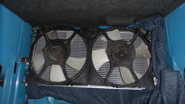
Your rad might be a little smaller...think Ruby914 used a scirocco style as well. He did a great job with a smaller rad in his clubnarp build thread. One fan on one side, one on the other and he reversed the motion on one. Unfortunately you also have to look at that work-of-art air ducting system that he made effortlessly...(insert jealous smiley here)
Link to the site:
http://clubnarp.com/
If you're set on the way you're headed that's great, just thought I'd throw this at ya...
EDIT: Also on the fan relays, you should still have the fuse box that you pulled from the engine bay of your Subie. It has the stock fan relays in it (mine were labeled FAN and there are 3-4 of them). Use that whole box if you can to make it easy on yourself. Need to run power to it and connect it back up the way it was.
Posted by: BIGKAT_83 Dec 9 2013, 10:24 AM
You can cool these subarus with almost anything. This is a 11" x27" fluidyne double pass radiatior. I run right at the thermostat 180 degress and driving the car the fans never come on at all until you are stopped in traffic. Even then they only run at half speed.
Posted by: Chris H. Dec 9 2013, 10:31 AM
What the... Bob you have one of every motorized thing in the world. 
Posted by: CptTripps Dec 9 2013, 12:29 PM
That is an awesome setup! Lots less intrusive than some of the radiator setups I've seen. The one in my Renegade conversion right now takes up 2/3 of that trunk.
I've got one "Fan Relay" coming out of my Hydra EMS ecu, so perhaps only one switch is good enough for my use.
I'd really like having a spare tire like that available if I need it.
Posted by: andys Dec 9 2013, 01:21 PM
I would turn the two speed on first at low speed and then when the temp increased switch it to high speed with the second fan.
On my car I turn on both fans at half speed at 190 degrees and if the temp gets to 200 degrees both fans go to full speed.
This is easy to do using 3 relays. Slow speed is the fans wired in series and then put them in parallel for full speed.
Bob,
I've got three different schematics of this setup, but this is the best I've seen. Yeah, I love the low/high speed function, but oddly enough, it stopped working. My manual fan low/high over ride switches work, so the PCM signal is somehow not getting sent. Time to do some troubleshooting! I'm thinking GM coolant temp sensor failure? I'd like to test it; would you happen to know the resistance values to look for? (slight hijack)
Thanks,
Andys
Posted by: BIGKAT_83 Dec 9 2013, 01:45 PM
I would turn the two speed on first at low speed and then when the temp increased switch it to high speed with the second fan.
On my car I turn on both fans at half speed at 190 degrees and if the temp gets to 200 degrees both fans go to full speed.
This is easy to do using 3 relays. Slow speed is the fans wired in series and then put them in parallel for full speed.
Bob,
I've got three different schematics of this setup, but this is the best I've seen. Yeah, I love the low/high speed function, but oddly enough, it stopped working. My manual fan low/high over ride switches work, so the PCM signal is somehow not getting sent. Time to do some troubleshooting! I'm thinking GM coolant temp sensor failure? I'd like to test it; would you happen to know the resistance values to look for? (slight hijack)
Thanks,
Andys
The GM LS1 sensor (thermistor) is 29k ohms at -20 degress C and 180 ohms at 100 degress C.
Posted by: CptTripps Dec 9 2013, 07:12 PM
I'm having one hell of a time locating a radiator anything close to the one you have. I started thinking about a compact sized radiator, and that took me to looking at two smaller radiators. I think the Boxster does something like that too.
What do people think about using two smaller motorcycle or quad radiators.
I could mount two of these, and put the Intercooler radiator in between them...all up front without taking up too much room.
Attached image(s)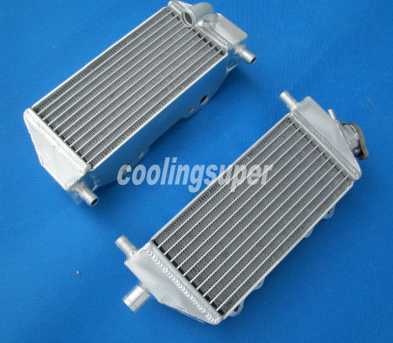
Posted by: 76-914 Dec 9 2013, 07:27 PM
Mike & Tom, Thanks for explaining things to me. Now I get it. Bob tried to tell me but I was too damn stupid to get it.  He must think that I know what I'm doing.
  Bob, if your still following, were those MegaSquirt pin numbers that you show in that print?
Posted by: BIGKAT_83 Dec 9 2013, 07:34 PM
Mike & Tom, Thanks for explaining things to me. Now I get it. Bob tried to tell me but I was too damn stupid to get it.
He must think that I know what I'm doing. Bob, if your still following, were those MegaSquirt pin numbers that you show in that print?Didn't mean to confuse you those are LS1 ecu pin numbers. I have two radiators set up like this one in the subaru car. Using two outputs out of the megasquirt to control the fans. The other one is the LS1 car and they are controlled with the stock ECU.
 Bob
Bob
Posted by: 76-914 Dec 9 2013, 07:44 PM
Spoke too soon. I see relay 2 powering Fan #1 @ high speed. I don't understand the "path" it takes to run Fan #2 on high. Sorry I'm so thick about this.
EDIT: Nevermind. I went back and read where Tom confirmed that both circuits are energized at the same time. God I hope I remember this tomorrow after I've slept.
Posted by: Mike Bellis Dec 9 2013, 08:02 PM
I'm having one hell of a time locating a radiator anything close to the one you have. I started thinking about a compact sized radiator, and that took me to looking at two smaller radiators. I think the Boxster does something like that too.
What do people think about using two smaller motorcycle or quad radiators.
I could mount two of these, and put the Intercooler radiator in between them...all up front without taking up too much room.
Horse Power equals heat. You need to be able to dissipate the heat. Most motorcycles make less than 100hp, so you would in theory need 4 radiators rated for 100hp to cool 400hp. It doesn't really work that way since it's not a linear equation.
Things to consider:
1) Surface area - larger surface area will have better heat transfer. Small radiators look cool but may not be cool.
2) Water flow - too much or too little water flow will reduce heat transfer.
3) Air flow - radiator must be sealed with a shroud to prevent air flow around the radiator. Air will follow the path of least resistance.
4) Confection - To create a low pressure area behind the radiator to promote air flow. Most of us accomplish this by having a larger outlet for air and a smaller inlet in the bumper. This creates a high pressure zone in front of the radiator.
5) Fans - fans must pull air through the radiator. Never push through.
6) Surface tension - Increasing the surface tension of the water can promote better heat transfer. This is accomplished by using a product like "Water Wetter" or "Purple Ice"
7) Tuning - an improperly tuned engine can create additional heat.
Posted by: BIGKAT_83 Dec 10 2013, 05:49 AM
I'm having one hell of a time locating a radiator anything close to the one you have. I started thinking about a compact sized radiator, and that took me to looking at two smaller radiators. I think the Boxster does something like that too.
What do people think about using two smaller motorcycle or quad radiators.
I could mount two of these, and put the Intercooler radiator in between them...all up front without taking up too much room.
Here's a couple for you. These are used on a 993 LS1 conversion.
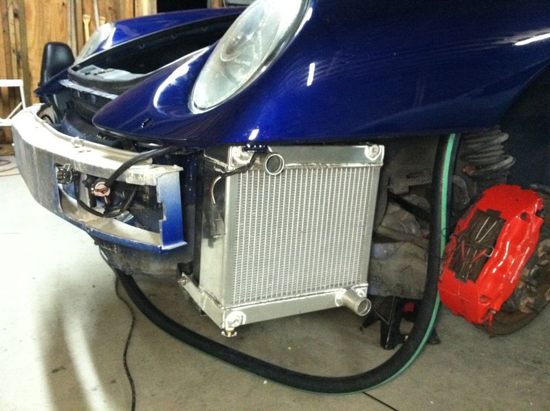
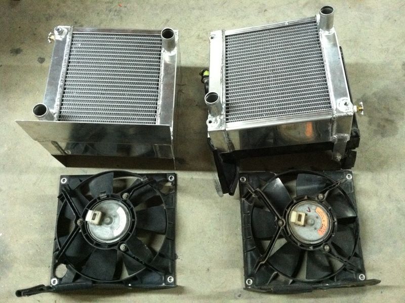
Bob
Posted by: CptTripps Dec 10 2013, 10:07 AM
That got me thinking...what about the front radiator for a Boxster instead of the side radiators? (It has 3, right?)
something like this one.
http://www.pelicanparts.com/cgi-bin/smart/more_info.cgi?pn=997-106-037-02-M6
Looks like it's small enough to fit down low. With 2 fans exhausting out the wheel-wells in a fiberglass/aluminium tunnel?
Posted by: Mike Bellis Dec 10 2013, 10:27 AM
That got me thinking...what about the front radiator for a Boxster instead of the side radiators? (It has 3, right?)
something like this one.
http://www.pelicanparts.com/cgi-bin/smart/more_info.cgi?pn=997-106-037-02-M6
Looks like it's small enough to fit down low. With 2 fans exhausting out the wheel-wells in a fiberglass/aluminium tunnel?
The center radiator was added to supplement the side radiators. I doubt if it has enough Delta T to be used by itself.
Posted by: CptTripps Dec 10 2013, 12:35 PM
YeH, that's what I'm thinking too. Looks a little small for what I'd need it for.
Back to the drawing board.
Posted by: skeates Dec 10 2013, 01:08 PM
I'm having one hell of a time locating a radiator anything close to the one you have. I started thinking about a compact sized radiator, and that took me to looking at two smaller radiators. I think the Boxster does something like that too.
What do people think about using two smaller motorcycle or quad radiators.
I could mount two of these, and put the Intercooler radiator in between them...all up front without taking up too much room.
Horse Power equals heat. You need to be able to dissipate the heat. Most motorcycles make less than 100hp, so you would in theory need 4 radiators rated for 100hp to cool 400hp. It doesn't really work that way since it's not a linear equation.
Things to consider:
1) Surface area - larger surface area will have better heat transfer. Small radiators look cool but may not be cool.
2) Water flow - too much or too little water flow will reduce heat transfer.
3) Air flow - radiator must be sealed with a shroud to prevent air flow around the radiator. Air will follow the path of least resistance.
4) Confection - To create a low pressure area behind the radiator to promote air flow. Most of us accomplish this by having a larger outlet for air and a smaller inlet in the bumper. This creates a high pressure zone in front of the radiator.
5) Fans - fans must pull air through the radiator. Never push through.
6) Surface tension - Increasing the surface tension of the water can promote better heat transfer. This is accomplished by using a product like "Water Wetter" or "Purple Ice"
7) Tuning - an improperly tuned engine can create additional heat.
A little "confection" goes a long way in many baking recipes, but I'm pretty sure that it's "convection" that facilitates the heat transfer between the radiator and the air

As long as you are matching HP figures on the radiators you will be safe (and in my opinion fairly conservative). One thing to keep in mind is that in our radiator set-ups we don't have a massive mass of metal inches behind the radiators. In fact, we have fairly un-obstructed paths for the air flow (particularly if you are ducting or venting through the hood) which dramatically increases the air flow rates and therefore capacity of the radiators.
Posted by: Mike Bellis Dec 10 2013, 07:39 PM
A little "confection" goes a long way in many baking recipes, but I'm pretty sure that it's "convection" that facilitates the heat transfer between the radiator and the air
Stupid spell check...

Posted by: 76-914 Dec 12 2013, 10:12 PM
Got my fans & relays wired in tonite  I'm happier than a 3 petered Billy Goat. It works great
  Thanks for all the help from everyone and thanks for that most excellent schematic, Bob.
Posted by: Chris H. Aug 25 2014, 11:22 AM
Gotta bump this great thread...Just a quick question...
Just ordered my 5 pin relays (the SVX stock ones are 4 pin), just trying to understand this diagram. I decided not to use the SVX fans since they are huge and when I started my car and let it run for 10 minutes and it didn't even come up to temp so I'm thinking that's overkill.
My new fans only have two wires (stock ones had 4). Assuming one is power and one is ground. On the diagram it's showing that I only ground ONE of the fans directly and then ground relay 3, which the second fan is connected to. Is that correct?
reposting the diagram:
Posted by: 76-914 Aug 25 2014, 05:20 PM
Es verdad, Christo. Looks funny but think of stacking 2 D cell batts. 6v or 12v depending upon whether the are in series or parallel.
Posted by: Chris H. Aug 25 2014, 05:22 PM
Cool thanks Kent! Just seemed weird not grounding the second fan directly.
Posted by: 76-914 Sep 1 2014, 10:06 AM
Thought I'd add this bit of info re: this style system. Last week I noticed that my fans were working on low but when switched to high (yeah, I was chasing a cooling issue) it dropped to Fan #2, only. Following the chart I was able to determine that relay F, in my case, (relay 3 in the diagram) was at fault. I was quite proud of my diagnostic abilities and proceeded to remove said relay to bench test and verify what I knew to be the problem. But the relay tested good. If it had been a snake it would have bitten me. And it's not like I didn't know it was there; I built the damned thing. I just forgot they were there. The fuses are now labeled for my benefit in case I blow another one. So if this one blows I get the above described scenario, however if the other one blew I think none of the fans would operate but you might want to double check me on that one. 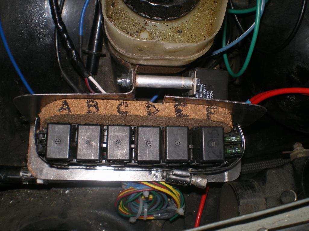
Posted by: messix Sep 1 2014, 10:54 AM
Thought I'd add this bit of info re: this style system. Last week I noticed that my fans were working on low but when switched to high (yeah, I was chasing a cooling issue) it dropped to Fan #2, only. Following the chart I was able to determine that relay F, in my case, (relay 3 in the diagram) was at fault. I was quite proud of my diagnostic abilities and proceeded to remove said relay to bench test and verify what I knew to be the problem. But the relay tested good.
If it had been a snake it would have bitten me. And it's not like I didn't know it was there; I built the damned thing. I just forgot they were there. The fuses are now labeled for my benefit in case I blow another one. So if this one blows I get the above described scenario, however if the other one blew I think none of the fans would operate but you might want to double check me on that one. you are correct.
I think if I built that circuit I would have activated the high speed on relay #2 from the 87 pole on relay #3. if the relay switching speed is not the same it would "buck" power.
so to do so you would run 2 wires off the 87 pole on relay #3, one to the fan and the other to the relay#2 at pole #85. only one high speed wire from the harness.
Powered by Invision Power Board (http://www.invisionboard.com)
© Invision Power Services (http://www.invisionpower.com)