Printable Version of Topic
Click here to view this topic in its original format
914World.com _ 914World Garage _ 9590 Valve Train Setup
Posted by: Highland Dec 17 2013, 12:26 PM
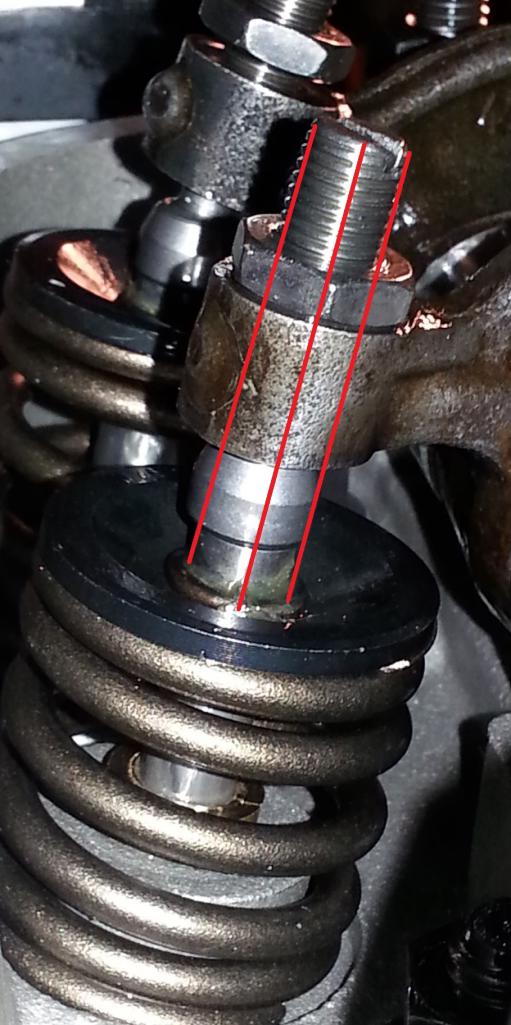
I started setting up the valve train for a 9590 cam with 0.426" lift for both exhaust and intake. I took some pictures at half lift and like to get some verification on this is what it's suppose to look like. I know the drawn in lines are not completely valid cause the picture is not perfectly square form the side.
Also RAT specifies to be within +/-5% of cam lift. Is within 5% cylinder to cylinder also okay? If not, what is a good target?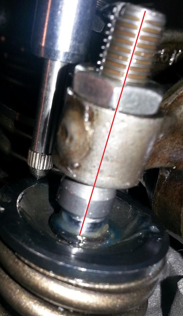
Posted by: nathansnathan Dec 17 2013, 12:34 PM
It looks like the adjuster isn't out enough. If it binds on the rocker, it's bad. Actually looks like the rockers aren't decked enough to run those adjusters.
I've always tried to get them the same as each other as it will affect adjusting them/synching them.
Posted by: Highland Dec 17 2013, 04:23 PM
Thanks for the input. I've got at least one turn before the adjusters bottom out against the rocker. Is that enough? A mill is not readily available, but of course I'll take down more if I have too. Took down .060 when I had them done.
Any opinions on how the geometry looks at 1/2 lift?
Also RAT specifies <0.006" play along the rocker shaft and to sand down the solid spacer to specification. Would replacing the provided washers with shims (instead of sanding the spacer) be okay or are those washers special?
Posted by: Mark Henry Dec 17 2013, 05:26 PM
If you removed .060 from the bottom of the adjuster screw hole now radius (grind, countersink) the hole so the foot swivels freely.
Posted by: Jake Raby Dec 17 2013, 07:03 PM

If you removed .060 from the bottom of the adjuster screw hole now radius (grind, countersink) the hole so the foot swivels freely.
Yep.
And it looks like the geometry is pretty close in these pics.
Posted by: gothspeed Dec 17 2013, 08:10 PM
Looks good 
Powered by Invision Power Board (http://www.invisionboard.com)
© Invision Power Services (http://www.invisionpower.com)