Printable Version of Topic
Click here to view this topic in its original format
914World.com _ 914World Garage _ Build #2
Posted by: jd74914 Dec 24 2013, 11:09 PM
Hello all.
I figured I’d throw up a progress thread for my car’s second rebuild. For those who don’t know me my name is James and I’ve been a 914 addict since age 13 (now 26) and used to hang around here a bunch more. It seems like a good start to this thread would be some background information. Its first build took place when I was in high school (age 13) and ended as a freshman in college. When I originally purchased the car it didn’t run and had some pretty serious external rust problems. I rebuilt the motor, fixed tons of electrical issues, replaced all of the rotten metal with new (all hand-formed since I didn’t have the money to pay for reproduction pieces), and repainted. Everything was done in my garage with the exception of turning/balancing the flywheel and I learned how to MIG weld and paint from my dad, some books, and through a lot of practice.
After reassembly, it was my daily driver for 3.5 years during my undergrad degree. I pretty much drove it hard and put it away wet for the entirety of these years and it never saw a garage. Something about getting a mechanical engineering degree, dating a few girls, working throughout the year as a design engineering intern, and finding FSAE cars really limited the amount of time I spend on my own car. By the end of my undergrad degree there were some pretty rough spots, mostly in terms of the suspension/brakes and a pesky ignition switch (replaced 3 or 4 times and it kept failing), which pushed me to taking it off the road and fixing everything correctly. I thought it might take about a year-that was 3.5 years ago! 
Just like after the first rebuild, life got in the way and the car sat as I went through a master’s degree, worked full time, continued to play with FSAE cars, and starting working on friend’s real racecars. Now I’ve finally finished my MS (and know way too much about fluid dynamics and heat transfer  ), am applying to schools for a Ph.D., still haven’t stopped [advising] FSAE design, and really want to drive her! The play was to start and finish rebuilding the suspension last summer (I saw Chris Foley-Racer Chris in the grocery store one day and told him this), but I got carried away and a bit behind. This thread is to chronicle the build back to the road.
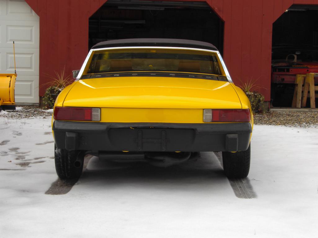
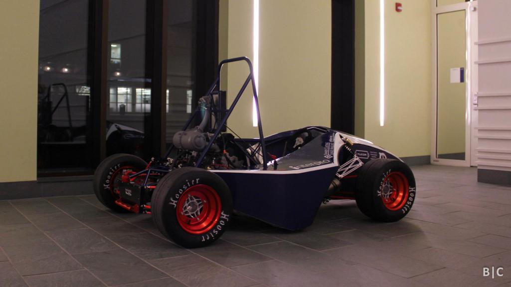
We’ll start with a few pictures from when it was originally completed in 2006/7 (well, it's missing the plates and still has the original windshield but...).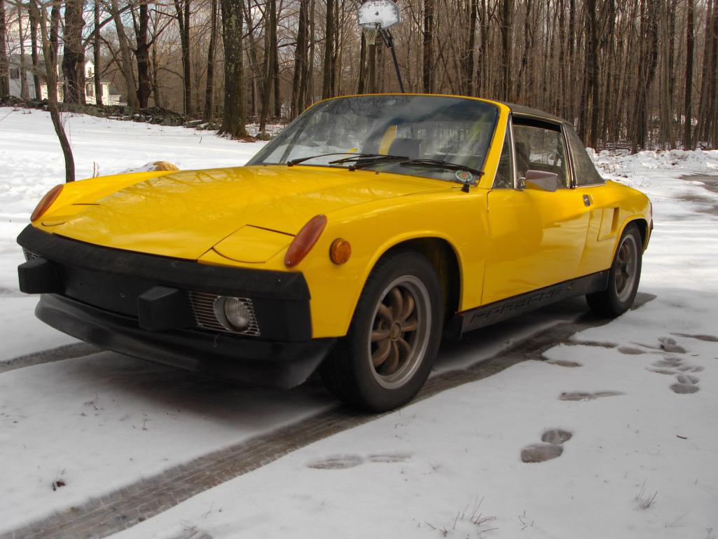
Posted by: jd74914 Dec 24 2013, 11:41 PM
***** Hijack Start *****
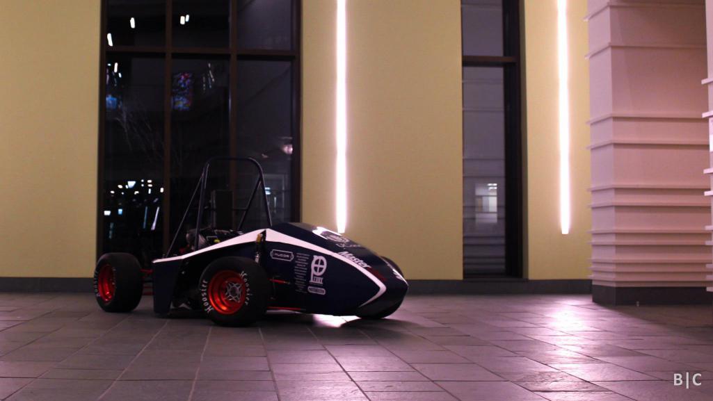
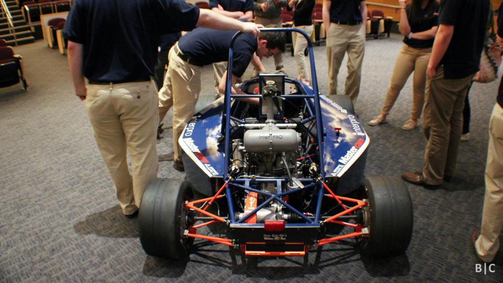
Since it’s been my main non-academic/vocational distraction for the last 7 years, a few OT FSAE pictures are probably warranted. For those who don’t know, FSAE is a college competition in which teams design and build a formula-style racecar for international competition. The cars are new every year, and the teams cycle members about every 3-4 years since they are academically-linked. I personally think it is the best learning experience for future engineers. And now for the sale’s plug: If anyone is interested in donating funds, components, or machining/RPing time, the guys would love to talk to you.
2013 UCONN FSAE Quick Spec. Notes
Suspension
10" wheels, 18.5x7.5" tires
Cast magnesium uprights
75 and 85 mm deep groove ball bearings
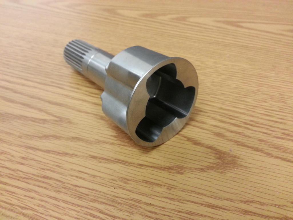
Custom "hindle" - Integrated hub, spindle, wheel center(6061-T6) with 4340 RC50 tripod inserts
Symmetric hindle design (same for all 4 corners)
LSA suspension, push-rod actuated dampers, front ARB
100% Ackermann
30 deg max steering angle
Kaz Tech/Cane Creek double-adjustable dampers
Brakes
Wilwood PS-1
Titon rear-pivot masters
Remote-mount bias adjust
Drivetrain
Semi-custom salisbury differential (built using BMW E30 LSD clutches and ramps)
Cast magnesium case, aluminum end caps
15.9# overall weight (including mounting pillow blocks, bearings, sprocket, stub axles, etc.)
Custom 4340 tripod stub axles
3 speed transmission, max speed 77.9 mph @ 12 krpm (which has problems eating gears...now drive 2nd and driven 2nd and 6th are cryo'd and shot-peened)
Chassis
4130, TIG welded, normalized
1800 ft-lb/degree twist
65# base frame weight, 70# fully loaded (not incl. stressed panels)
CFRP stressed floor, firewall, rear bulkhead
435# assembled weight goal (haven't weighed yet)
Engine/Controls
2001-2003 GSX-R600 motor
13:1 compression
Est. 85 hp @ 9.5 krpm, 45 ft-lb @ 8 krpm
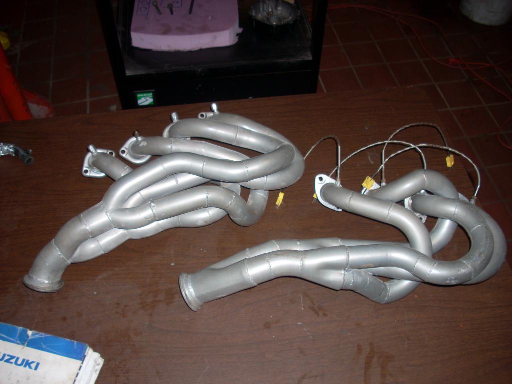
Eq. length 4-2-1 headers tuned for 2nd resonant freq. @ 7.5 krpm, 18 ga mild steel, ceramic coated
Ti Akropovic muffler
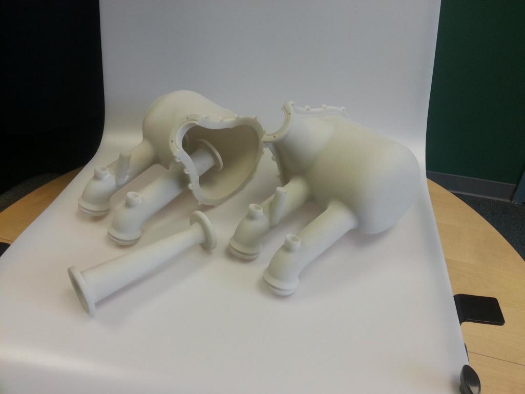
Intake tuned for 2nd resonant freq. @ 8.5 krpm, 40% glass-filled nylon SLS
28mm SLS throttle body
Performance Electronics PE-3 ECU
Texense shift cut (programmed ignition cut in ECU for clutchless shifting)
Manual shifter/hand clutch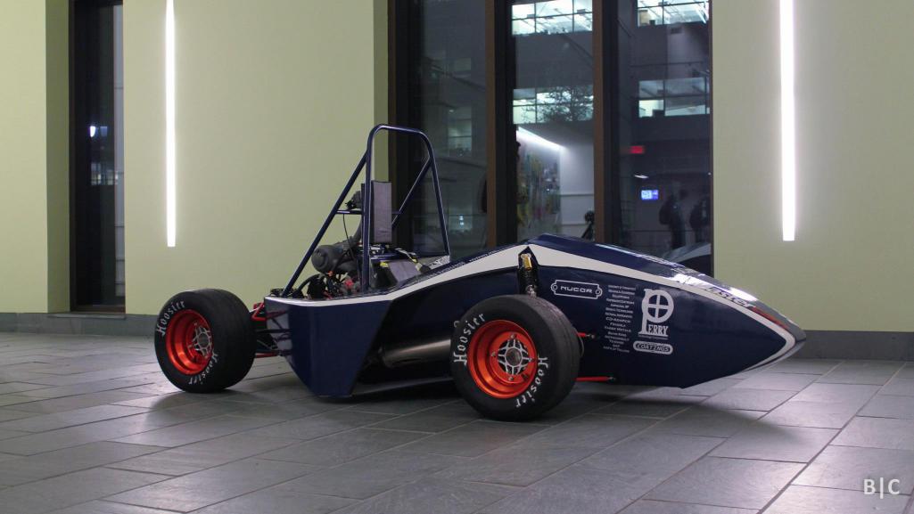
Posted by: jd74914 Dec 24 2013, 11:46 PM
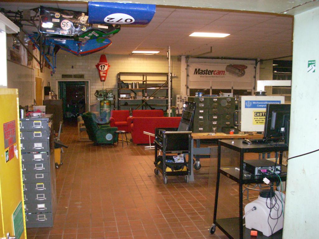
And a few shop pics just because...There is a nice Stuska dyno, manual lathe, and pretty OK design room with computers as well (always looking for more CFD/FEA machines ).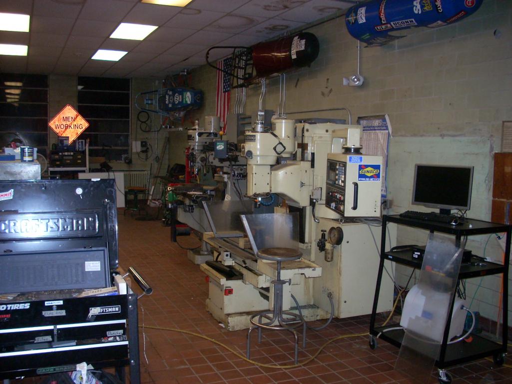
***** Hijack over - Back to normal programming *****
Posted by: RobW Dec 25 2013, 07:31 AM
Good luck with your build(s)....
Posted by: r_towle Dec 25 2013, 10:40 PM
Good to see you back at it again, now stop getting distracted and get her going again.
You may want to research the option of a push button starter switch like some race cars use, along with the reliable power function of the ignition switch.
Rich
Posted by: jd74914 Dec 25 2013, 11:55 PM
Thanks Rich and Rob...I'm definitely trying to get her going...albeit somewhat slowly as I'm pretty easily distracted.
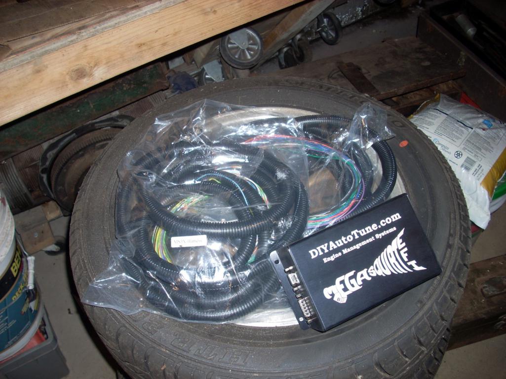
My initial plan (May 2013) was to replace the stock EFI with a MegaSquirt3. When I was actually driving the car, I had been having problems with intermittent failures and random broken wires. Figuring that these problems were mostly related to the 40 year old wires, the easiest solution seemed like remaking the FI harness. After thinking about it a little more, it seemed like a waste to remake an entire wire harness and still be handicapped by an antiquated controller. I’ve had experience building harnesses and tuning with a few aftermarket engine management systems [Performance Electronics PE1 and PE3, Adaptronic e420c, MicroSquirt] through FSAE and some other modified car builds so I picked the MS3 mostly for the cost and fact that I haven’t had the opportunity to play with any newer MS stuff.
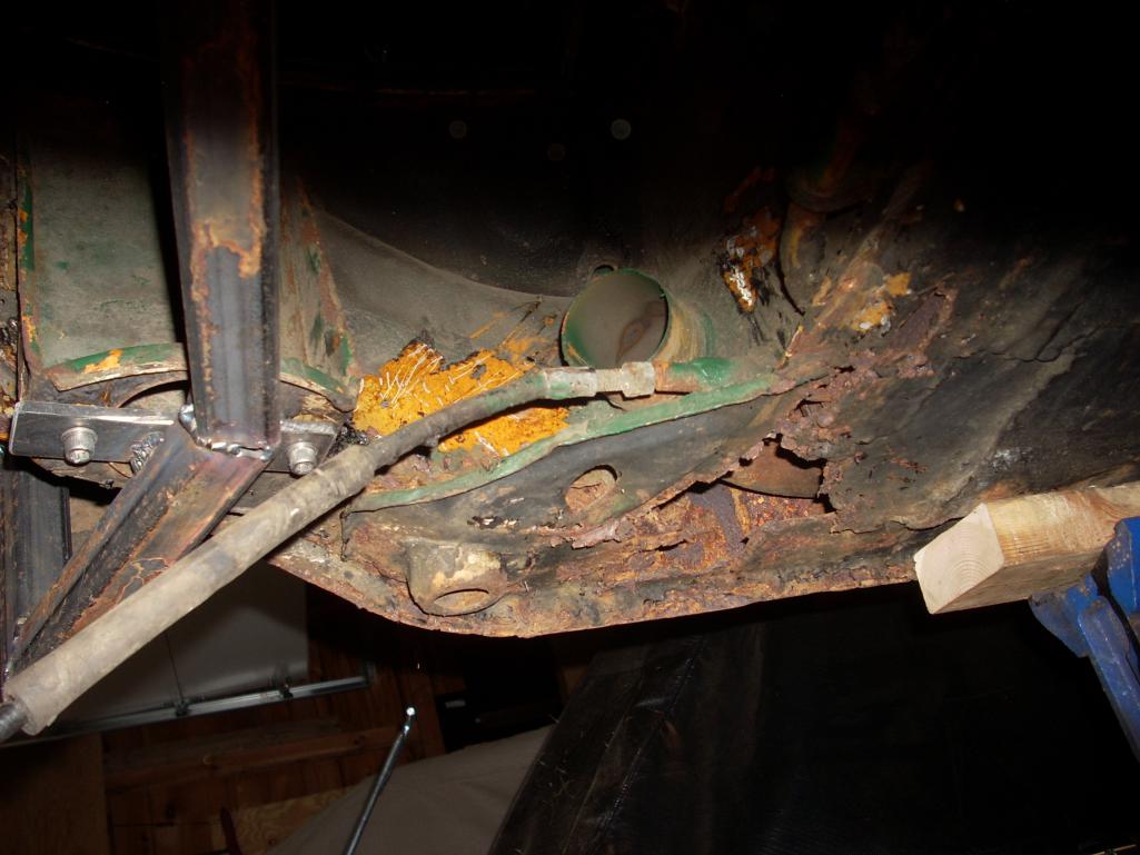
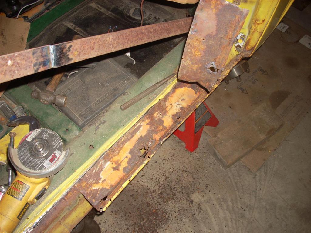
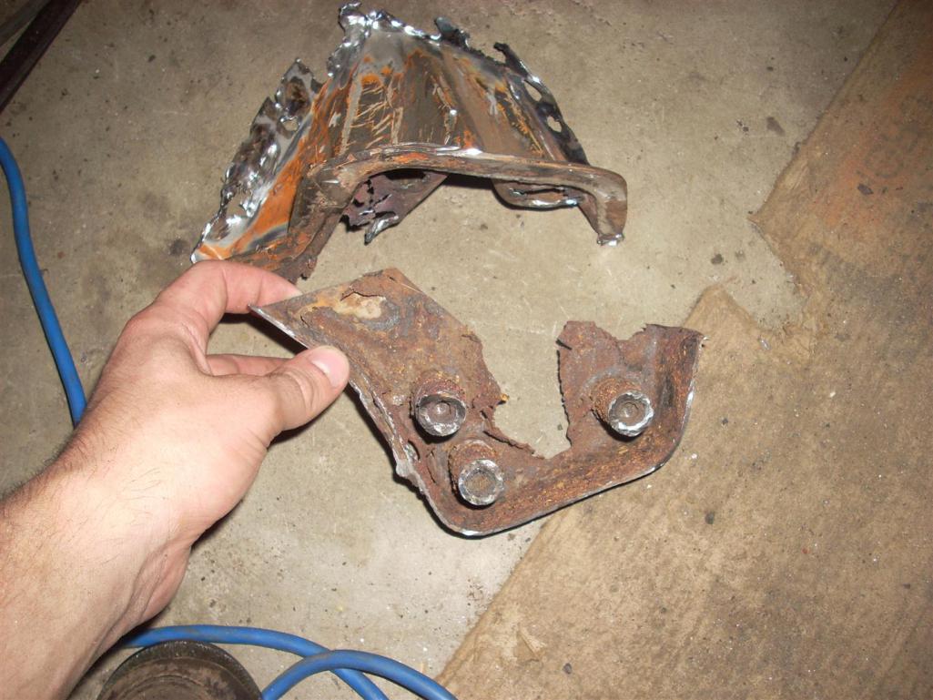
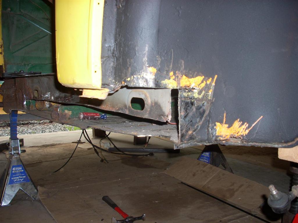
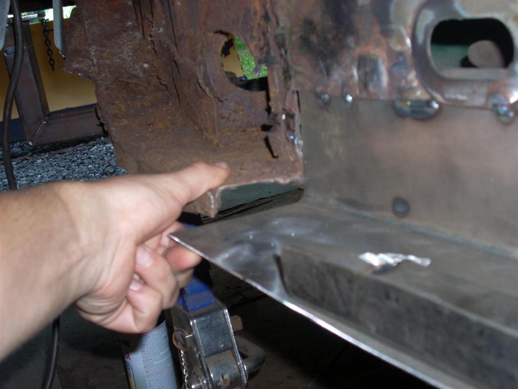
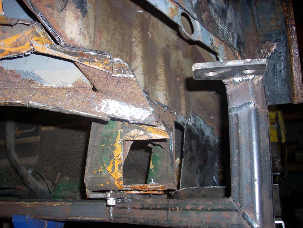
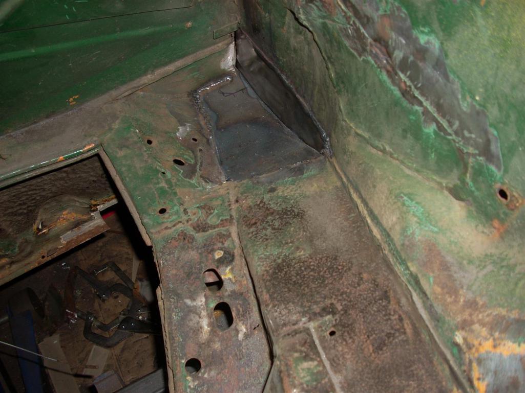
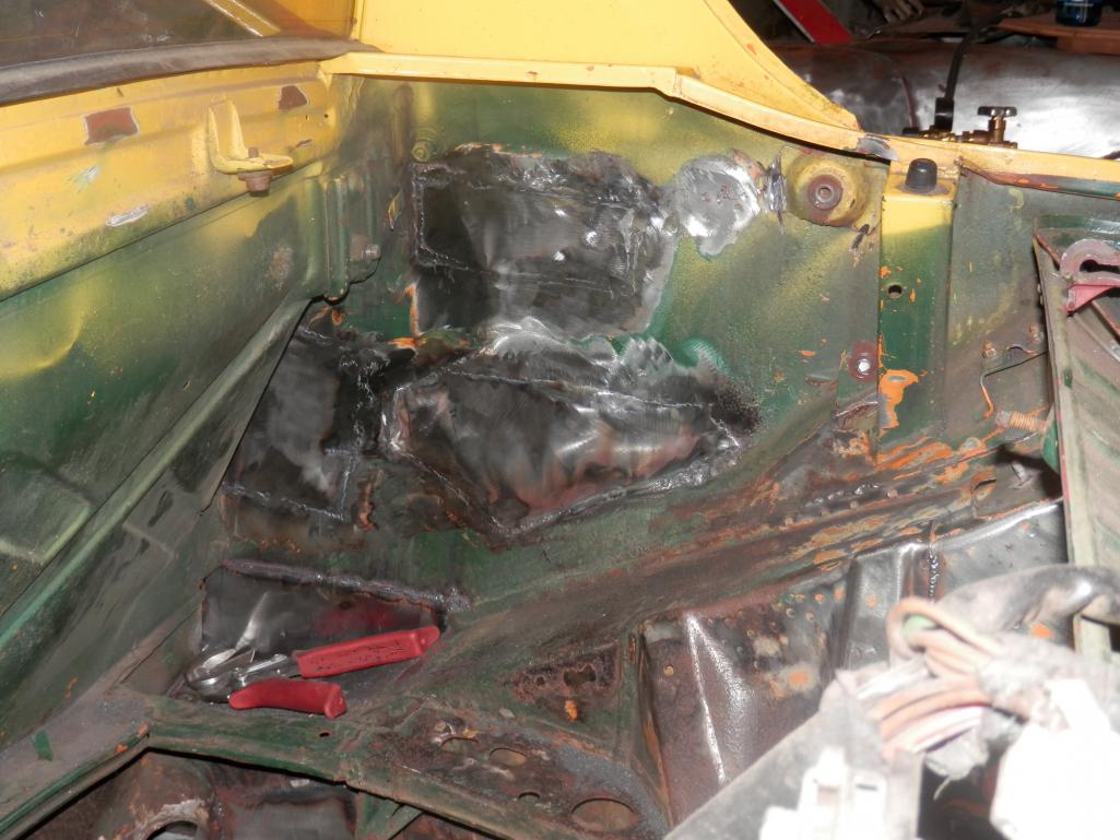
The first step in any harness build is measuring out the harness end locations, so I pulled the motor to measure wire lengths, add cam/crank position sensors, reseal the oil cooler, and repaint the tin. As I was doing this I noticed some rust on “jacking” donuts and rear right trailing arm mounts so out they came. While in there I started poking at the frame rails and noticed some rot so out they came as well.
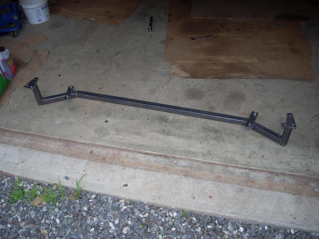
The first few pictures show some of the damage and then the quick suspension jig made to keep everything aligned after cutting. The door jams are also braced with angle welded from the upper seat belt bolt mounts to lower door jambs.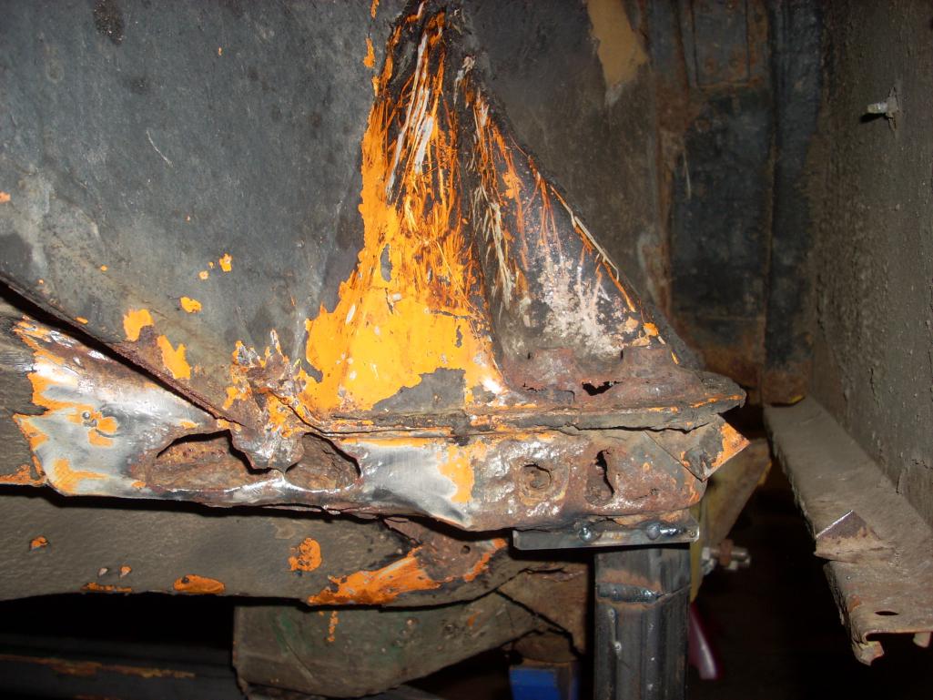
Posted by: jd74914 Dec 26 2013, 12:04 AM
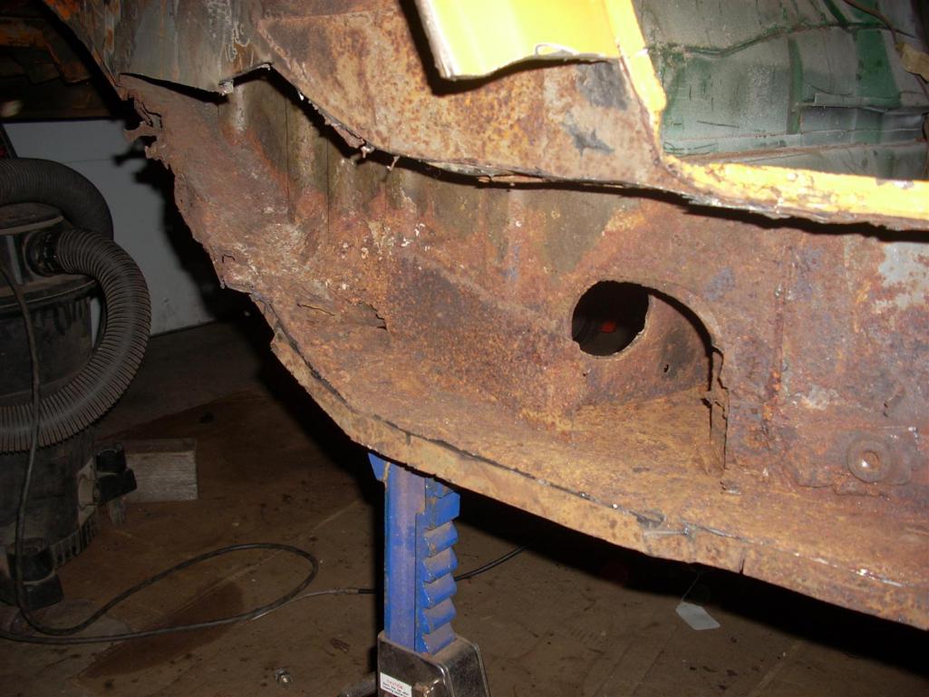
Off came the fender for easy cutting into the longs. That's only a little rust, right?
Note the old patch (80's perhaps) on the bottom left part of the image.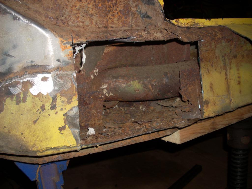
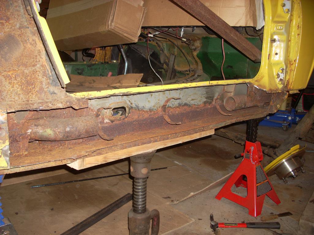
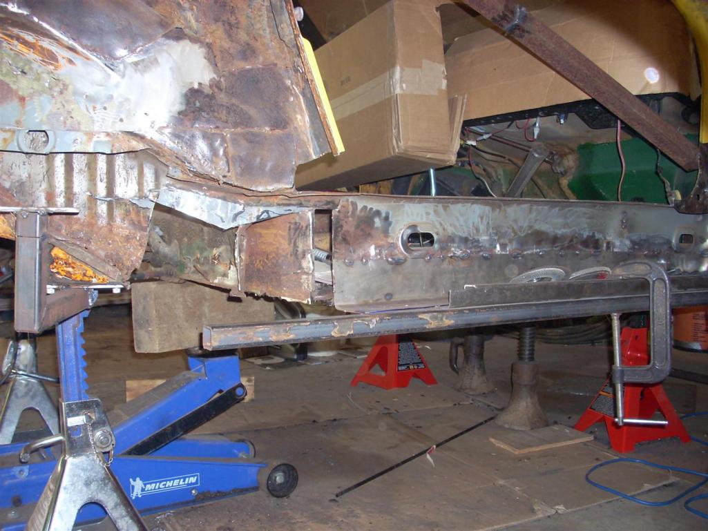
A view from the back (read: I hate jack posts).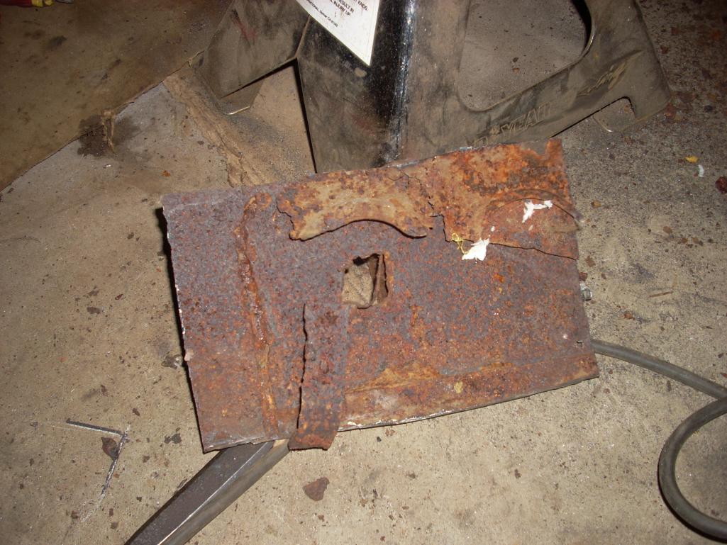
Don't you love thresholds covering old rusty thresholds? 
Posted by: jd74914 Dec 26 2013, 12:15 AM
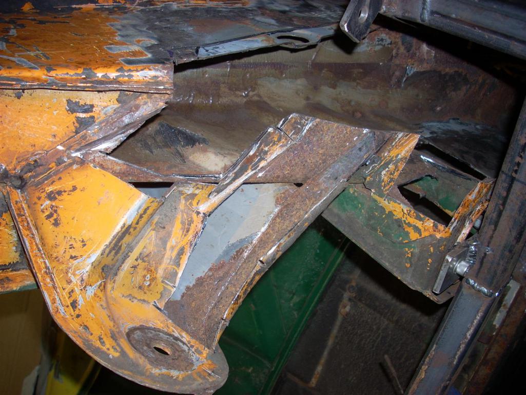
Once the cutting started, I had a really hard time stopping...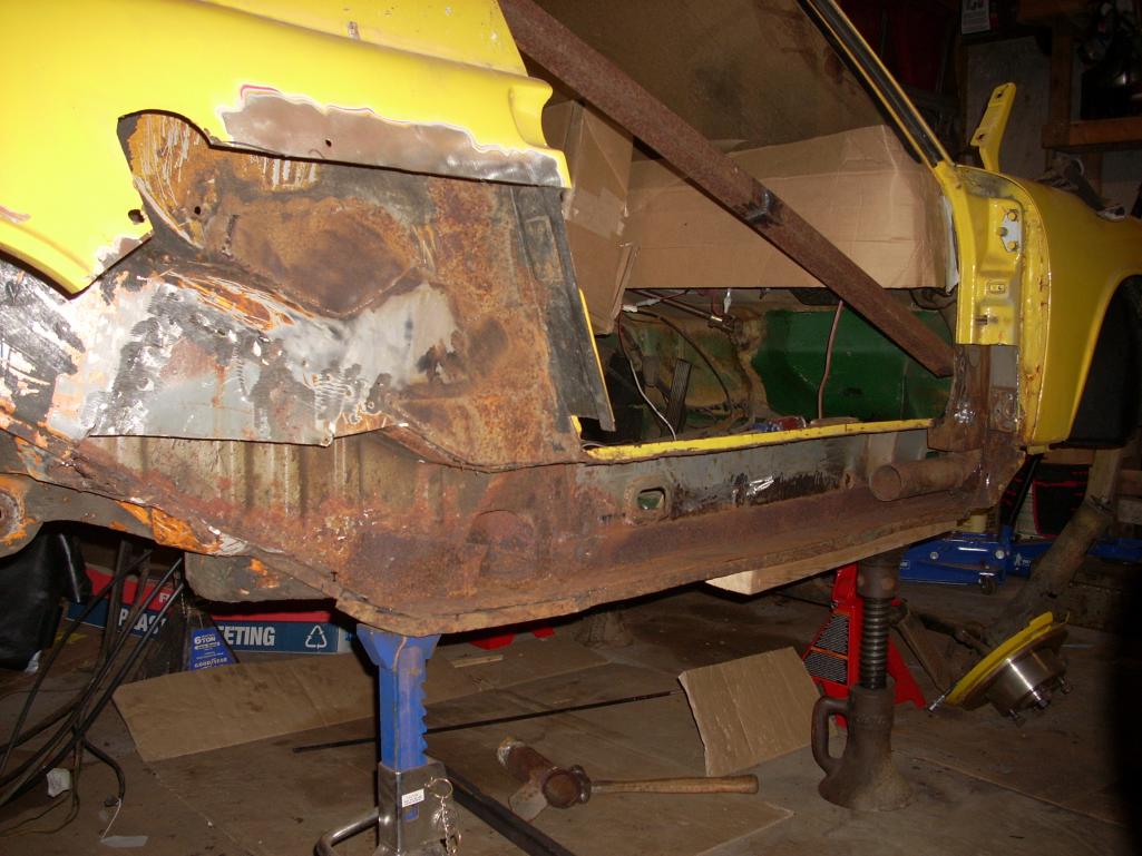
Posted by: jd74914 Dec 26 2013, 12:38 AM
A few more pictures of the suspension console and long. deconstruction.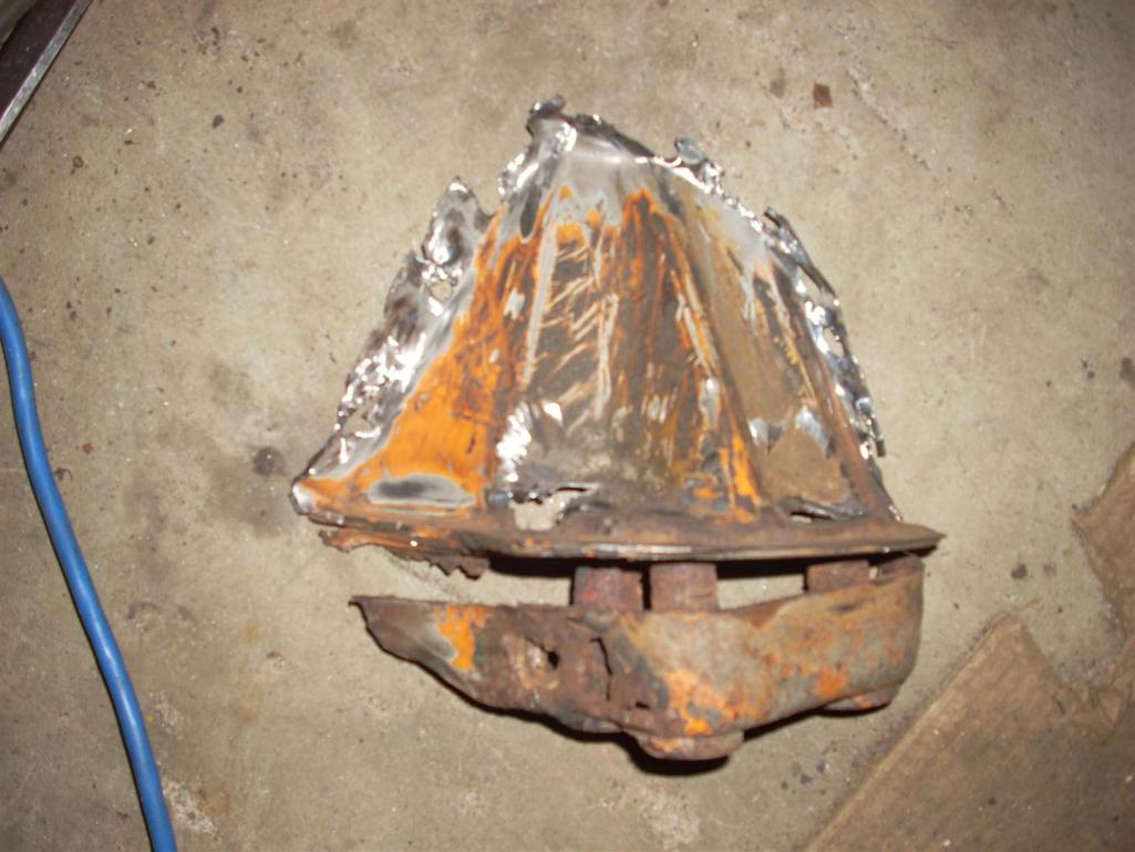
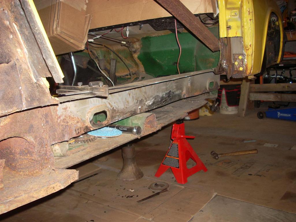
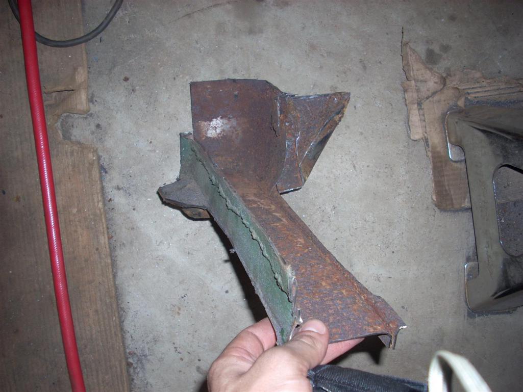
I'm on the quest to get everything up-to-date so more to come tomorrow.
Posted by: Cairo94507 Dec 26 2013, 09:17 AM
Terrific story and glad to see you are working towards your Ph.D - single biggest factor in being able to continue playing with our cars. I love seeing these cars go under the knife to repair their rusting bones. Best wishes and have fun restoring your lifetime friend.
Posted by: jd74914 Dec 27 2013, 01:59 AM

Terrific story and glad to see you are working towards your Ph.D - single biggest factor in being able to continue playing with our cars. I love seeing these cars go under the knife to repair their rusting bones. Best wishes and have fun restoring your lifetime friend.
Thanks!

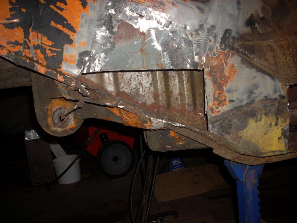
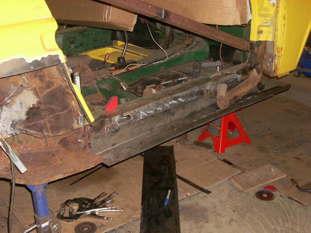
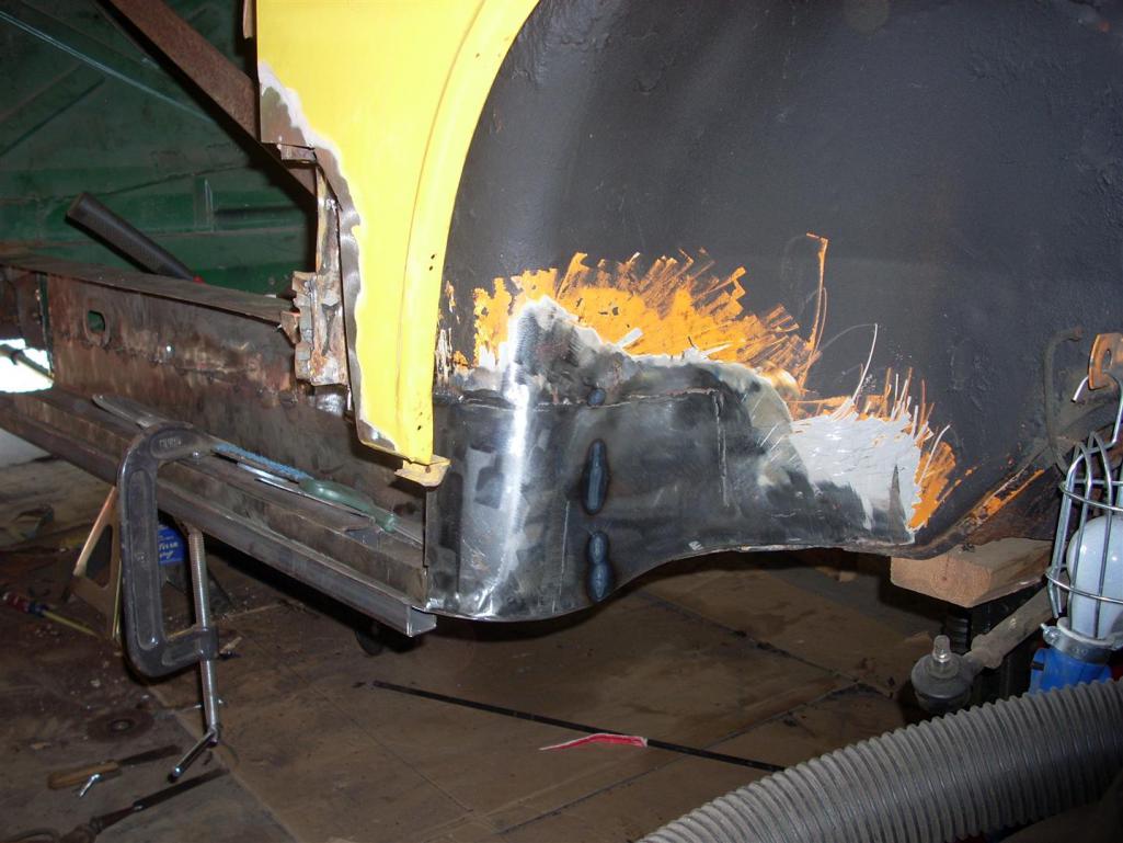
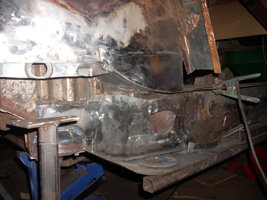
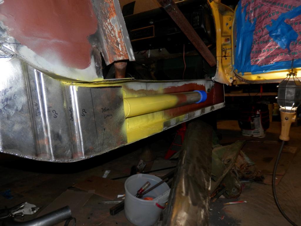
The last pictures ended with about 60% of the right long pulled off and a whole bunch more metal cut out. Since the car was dimensionally-unstable at this point, the immediate need was to fix most of the structure. The next pictures show the first portion of the inner long fix.
You'll notice that I'm not remaking the metal in exactly the same fashion as it was removed, it's actually about 12mm taller than the original cross-section and will have extra stiffening plates installed on the top and bottom faces. This modification increases stiffness more than an Engman kit (I'm tired now, but I'll write in the moment of inertial calculations later) without adding much additional weight (it's stiffness-to-weight efficiency is actually much better than Engman's and slightly better than the factory). It also has the added benefit of being essentially free since I'm making all of the pieces from sheet anyways. The oddly placed channel is for this buildup. When I get to posting the math details I'll also post a sketch of the new metal so everyone who wants can see how I'm adding it.
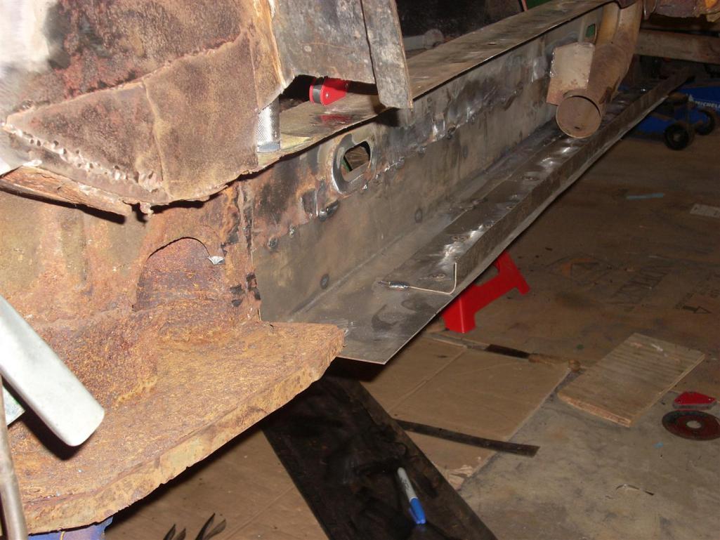
The inner fender well repair panel needed to have a slightly odd end finish to match the frame rail end, but I think it came out pretty nicely.
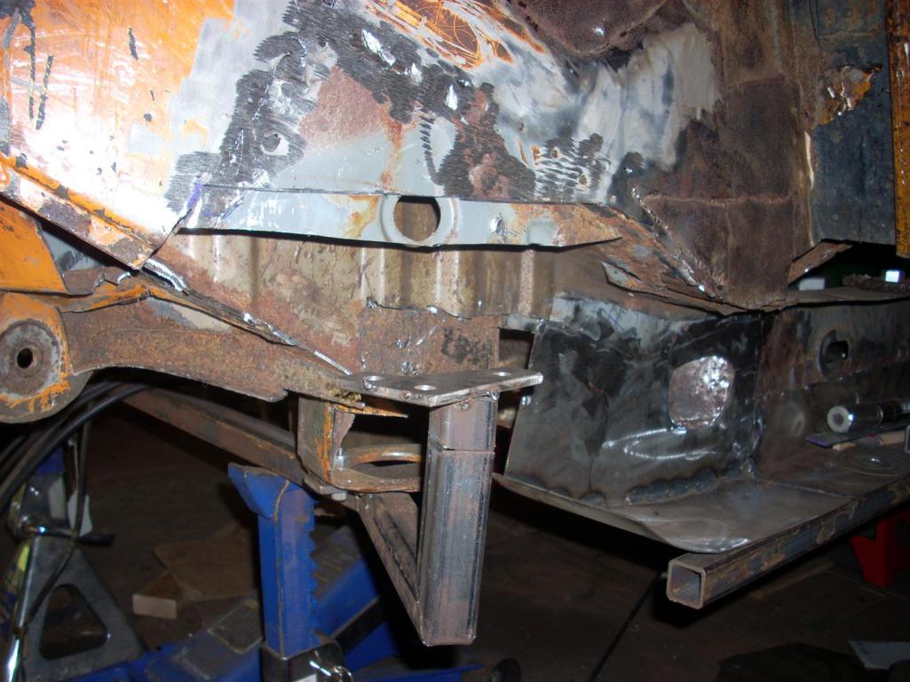
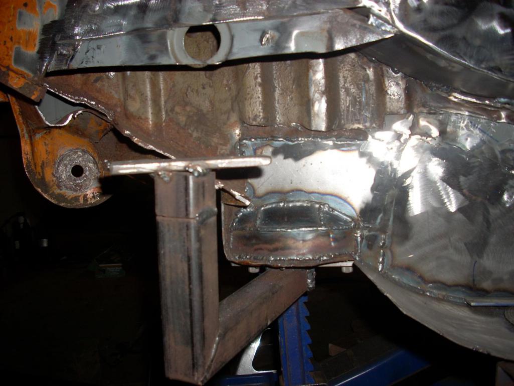
The rest of the pictures show some additional metal replacement at the engine mounts and hot air inlet duct section. Chances are these heater ducts will not come back in as originally intended and will instead become wire chase-ways for the ECU. The duct cutout in the new metal at duct inlet is funny looking (weird non-oval shape) since it has yet cut to the exact opening. The hell hole bottom wasn't too bad, but while in there seemed like a prudent replacement.
That's all for now...so enjoy some pictures.
Posted by: Racer Chris Dec 27 2013, 07:59 AM
Wow, a little bit of project creep there. Better now than later though.
Looks like a good time to install a raised suspension pickup kit while you're at it.
We have a chassis here which needs much of the same repair work.
Ed's busy bolting it down to our Slutty bench right now.
Posted by: r_towle Dec 27 2013, 06:38 PM
When the heck did you do that? Last week?
And Chris, I must have missed the slutty bench last time I was there, it's on my must see list how.
Posted by: jd74914 Dec 27 2013, 11:52 PM
Wow, a little bit of project creep there. Better now than later though.
Looks like a good time to install a raised suspension pickup kit while you're at it.
Yes, just a little scope creep. I figured it'd be nice to build what I [think I] want the first time around. I just raised the front spindles and have been thinking about the rear.
Ed's busy bolting it down to our Slutty bench right now.

When the heck did you do that? Last week?
Hahaha A few weeks ago...I'm trying to get everything up to date now.
--------------------------
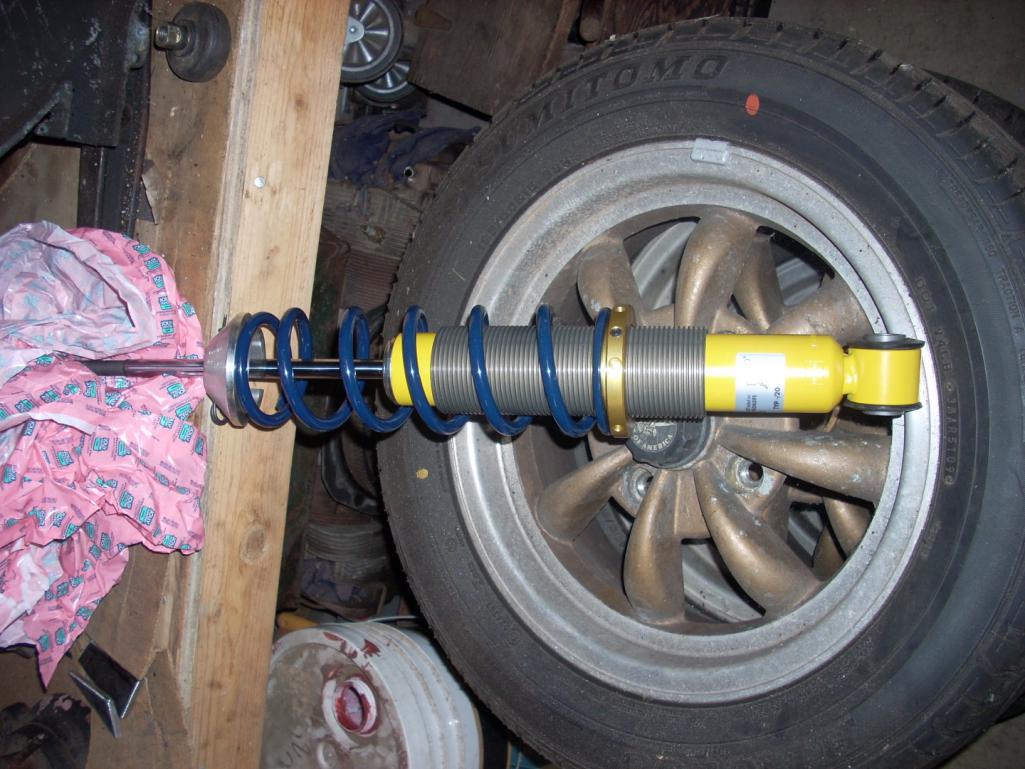
As a change of pace I raised my front spindles 18mm (slightly under the fit limit of a 15 inch wheel). Since I started with tapered Boge struts, raising required a little sectioning rather than a simple weld cut, press, and new weld. I sectioned a length from the strut top, cut the strut bottom, and then TIG'd the spool in. Note that the sectioned piece needed to be tacked and then shaved length-wise to fit the strut bottom's smaller dimensions. Unfortunately, I didn't take pictures of the process, only the "final" product.
Note that I'm going to put a RSR-style double shear tie rod mount onto the strut, machine a tapered bolt to fit the existing tie rod end, and a few spacers to play with the bumpsteer.
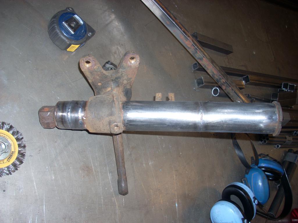
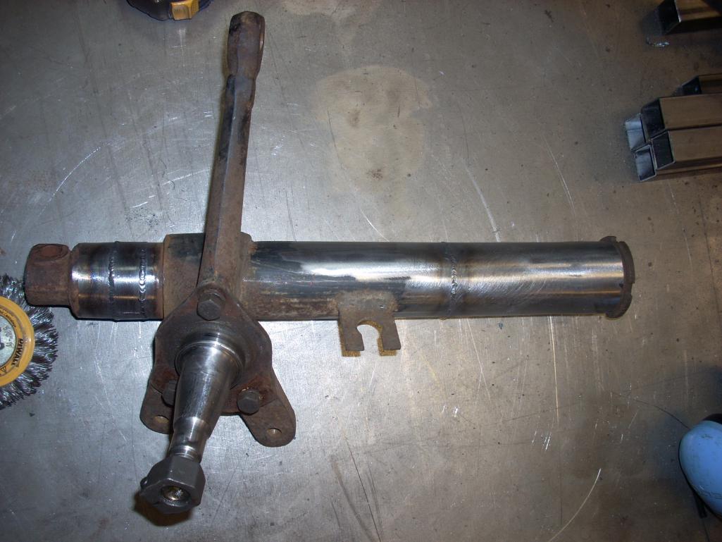
*The strut housings are straight despite ho they might look in pictures.
Posted by: saigon71 Dec 28 2013, 08:45 AM
Looking good...especially the jig to insure the suspension console is in the right spot.
In my experience, project creep just happens with these cars.

Posted by: jd74914 Dec 29 2014, 03:09 PM
A late thanks Bob!
I was going through my camera and found some pictures of the next steps of this project (only a year after the last post haha).
In the past year I've jet-set all over the place for work, lost my job due to company bankruptcy, signed up for full time doctoral research in laser diagnostics, started an engineering consulting gig, had the opportunity to play with LeMans-grade engine control hardware (see Life Racing F88) and way too much more so my 914 progress has been super slooooooooooooooooooow.  Hopefully life will let me get a little more done this year!
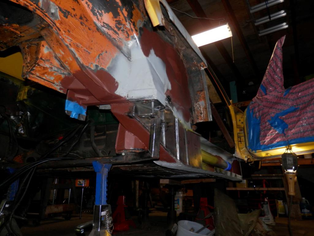
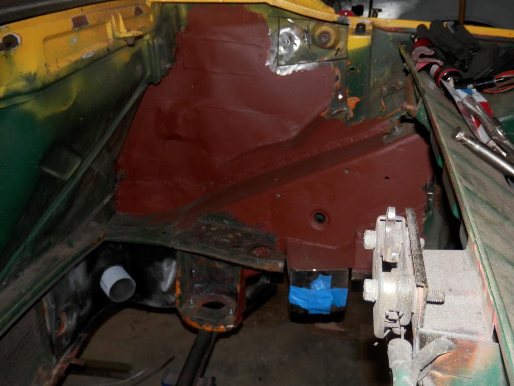
The first pictures show fixes to the general inner fender structure where the metal was either soft or had been poorly replaced the first time around. 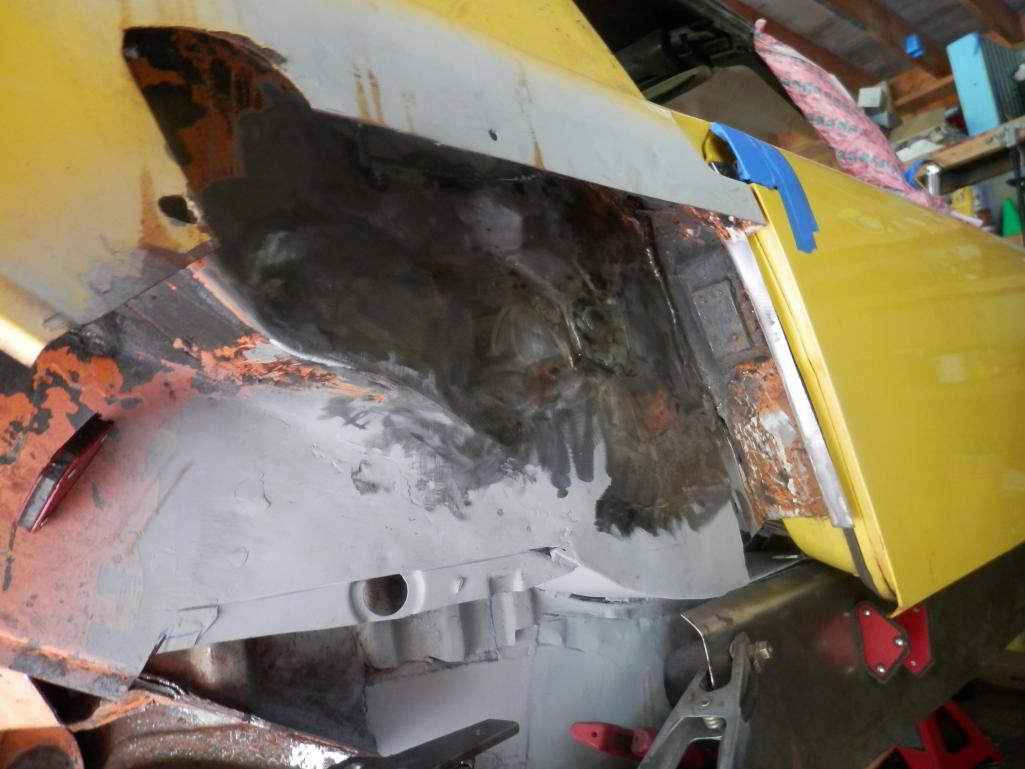
Posted by: jd74914 Dec 29 2014, 03:10 PM
Posted by: Racer Chris Dec 29 2014, 03:15 PM
...
, lost my job due to company bankruptcy,
...
How convenient for the new company to run out of money so quickly. Previous owner seemed to make it work for the long term.
I wondered how you made out when that happened but figured you would land on your feet either way.
Posted by: r_towle Dec 29 2014, 03:23 PM
is the car originally green, orange, or yellow?
Posted by: jd74914 Dec 29 2014, 03:43 PM
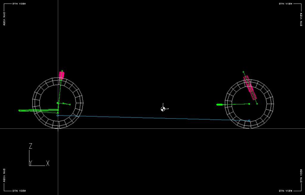
Over the course of last winter, I couldn't stop thinking about lowering the rear of the car. Unfortunately, I wasn't comfortable dropping the roll center super low just by cranking down on a set of threaded spring perches without making any kinematic changes. I actually drew up both the front and rear suspension in a kinematic software I have access to and looked into modifying the pivot points, etc. Through this modeling I decided to raise the rear trailing arm mounts (just as a note changing from trailing arm to multi-link suspension was considered, but in the end I decided to stay semi-trailing arm since an suspension genre switch is really easier in a full custom car).
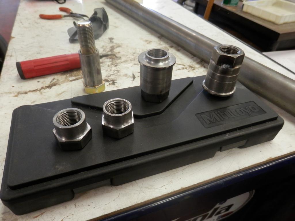
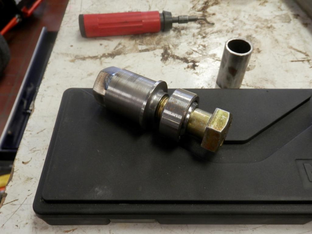
Additionally the car needed new bushings. As this project was moving more into the realm of questionably street-able I decided to try something different and switch to spherical bearings in the rear pivots. I'm still a little worried about how they are going to work, but my rationale was that in the worst case I would just throw away my modified arms and cut the inner pivot out of the car for replacement with something a different. The cost to change is pretty low so I'm not too worried; the most disappointing part would be throwing away the machining necessary to make the new "pivot shafts."
Just for size reference, the sphericals have a 3/4" bore. I went with this size because it most closely matched the size of the existing pivots. I don't remember the exact numbers, by the factor of safety for the spherical (radially-loaded) is something like 8 if the car experiences a 3g bump, 2g brake, and 2g lateral load all at the same time with the entire weight of the car on a rear wheel.
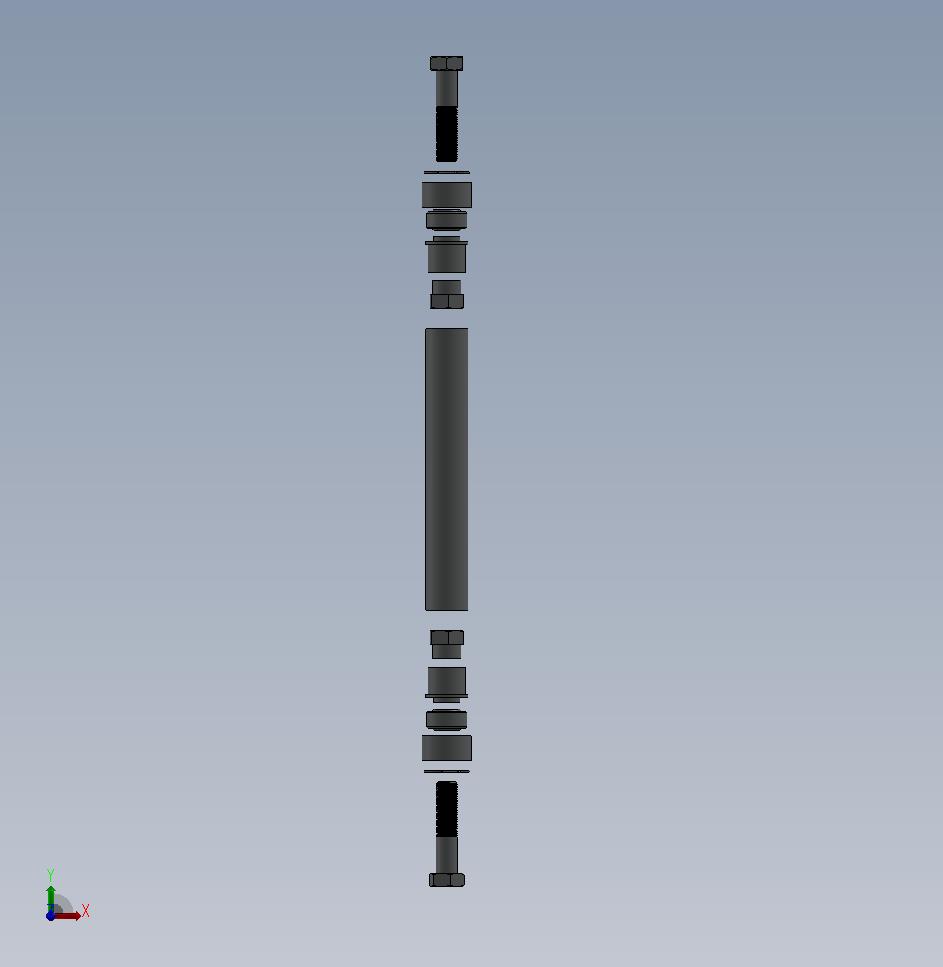
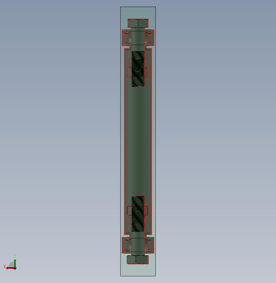
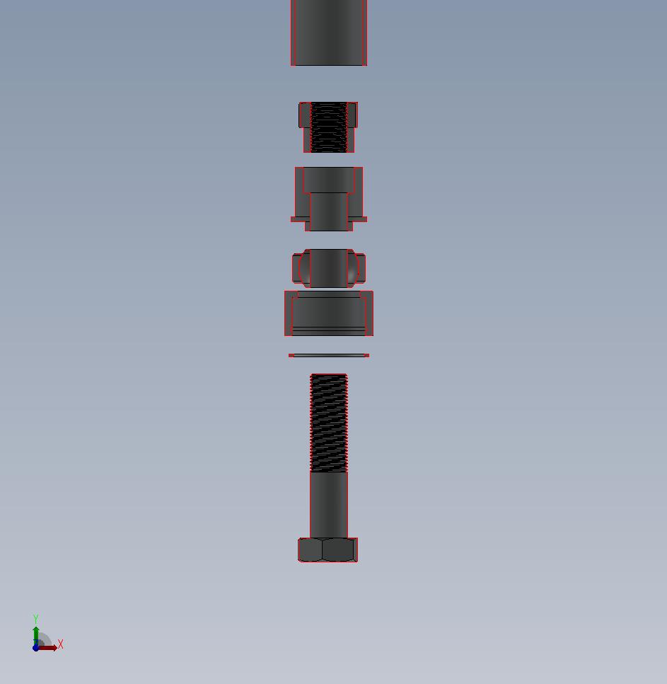
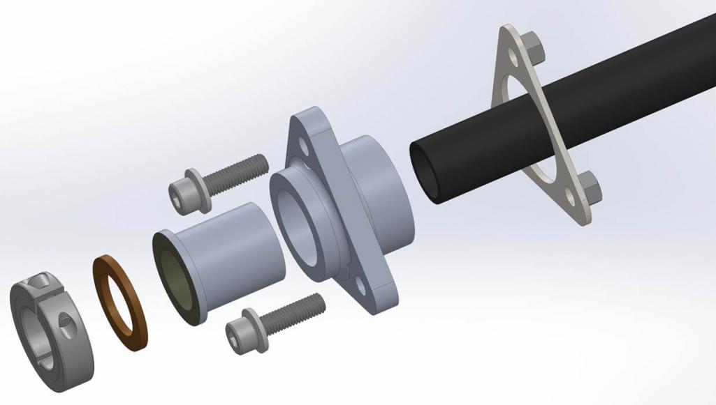
Anyways, the next pictures show a little suspension modeling (no real kinematics unless some really wants to see plots) and then the trailing arm inserts. They were machined as such because I did not want a stress concentration for the bolt at the trailing arm/spherical interface. As designed, the bolt shank goes through the spherical and into a flat in the trailing arm and the the threaded portion starts. The tube everything is combined in gets pressed into the trailing arms and the edges welded. I don't have pictures of the part but it all went pretty smoothly.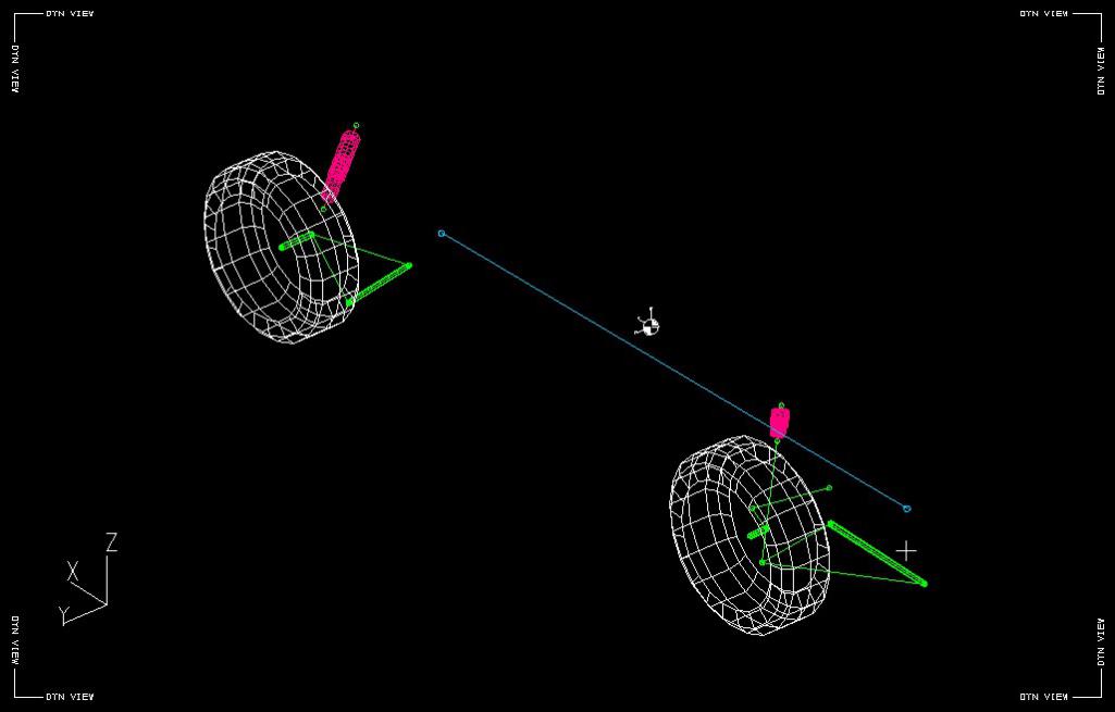
Posted by: jd74914 Dec 29 2014, 03:46 PM
...
, lost my job due to company bankruptcy,
...
How convenient for the new company to run out of money so quickly. Previous owner seemed to make it work for the long term.
I wondered how you made out when that happened but figured you would land on your feet either way.
Yup, there was definitely some funny business there. It's not owned by a Korean company who seems to be in it more for the long run which is good since, while expensive, the product does work well.
is the car originally green, orange, or yellow?
Hahahaha Original color is orange. I thought I wanted a green car so the innards are green and then after seeing it I decided I actually wanted a yellow car. It's slowly getting back to more yellow. Once it's finished this time around everything should be yellow.
Posted by: jd74914 Dec 29 2014, 03:59 PM
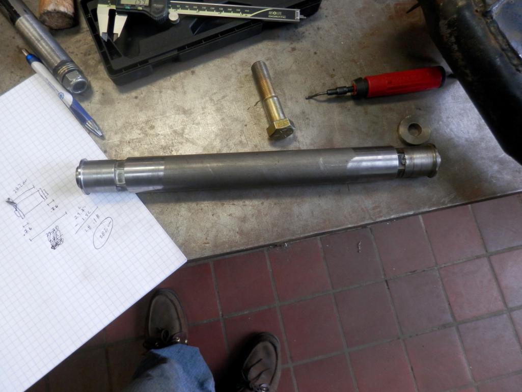
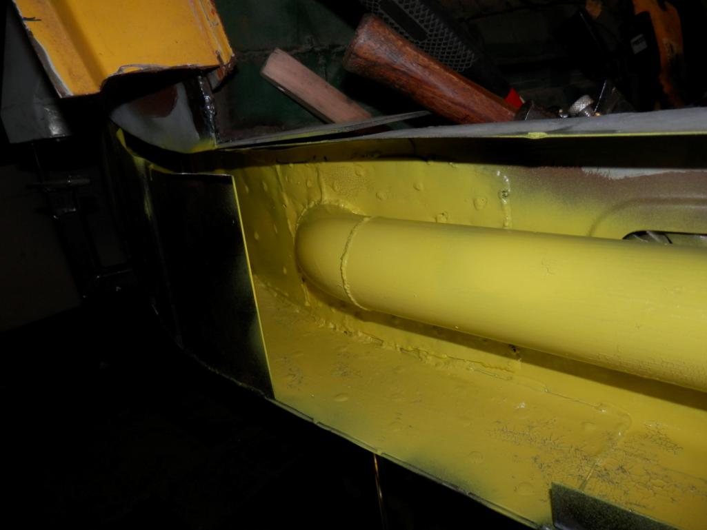
The trailing arm mounts were moved up by about 1.8 inches and completely remade. When I took out the old outer mounts 4/6 bolts snapped so remaking them was altogether easier than drilling out the bolts and retapping. At the same time I remade the longitudinal structure.
The longs themselves were redesigned and made taller with slightly different metal thicknesses/layering. This was done to increase the vertical moment of inertial and improve the car's bending stiffness in this area. From a design perspective, the new geometry (more or less 0.5" taller with some strategically sized metal thicknesses) results in a 246% bending stiffness improvement over stock with a stiffness/weight efficiency (in terms of moment of inertia/cross-sectional area) of 4.927e3 mm^4/mm^2 vs the stock efficiency of 4.042e3 mm^4/mm^2. Overall weight increase is about 27 pounds. For reference the Engman kit (best as I can tell since I haven't held one) weights 18 pounds and increases stiffness by 168% assuming an OEM long to start with.
You'll note that it will still be double layered with the corrugated inner. The insulated heater tube was removed and a solid tube put in its place. This might get used as a wire tray later. Anywhere there are butted seams there is also a backer lap joint.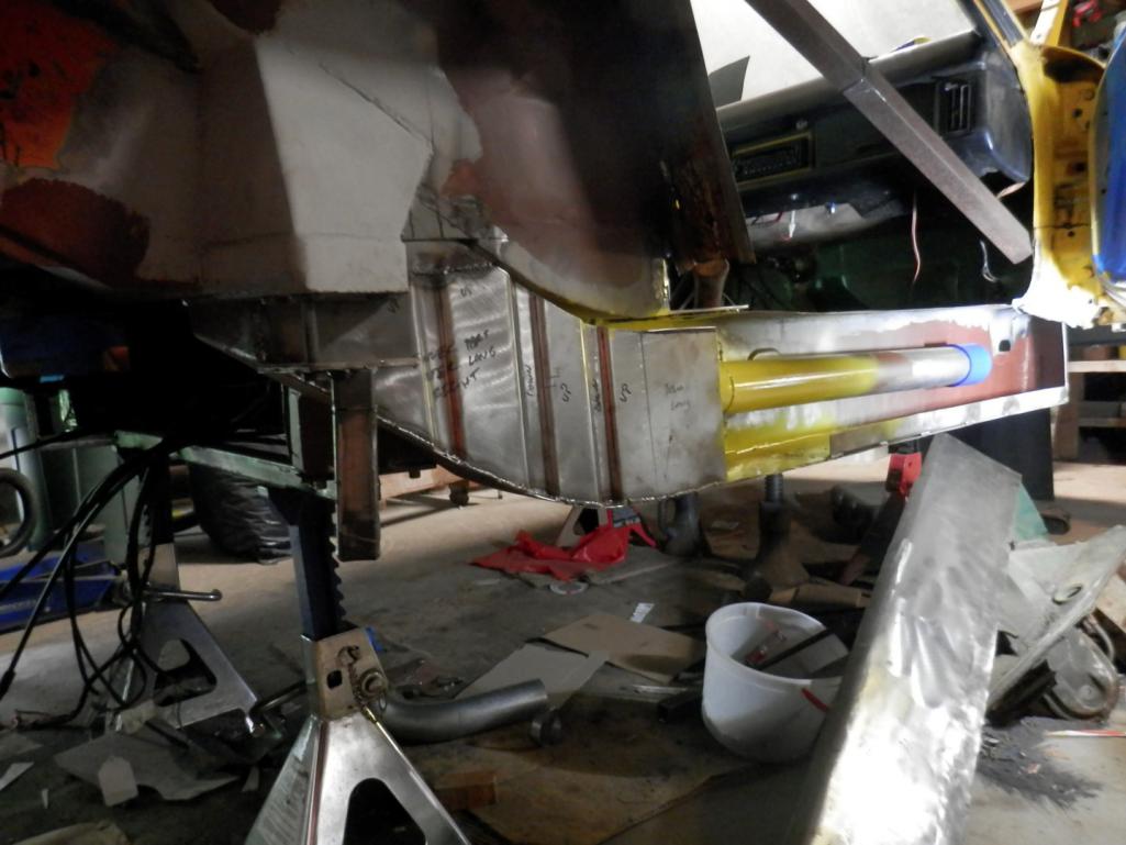
Attached thumbnail(s)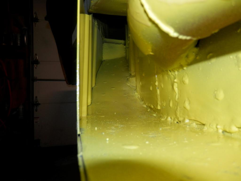
Posted by: jd74914 Dec 29 2014, 04:08 PM
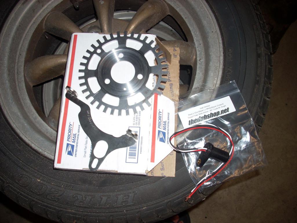
And just for fun some new stuff...
The trigger wheel is from Mario at The Dub Shop and I do need some tender springs. 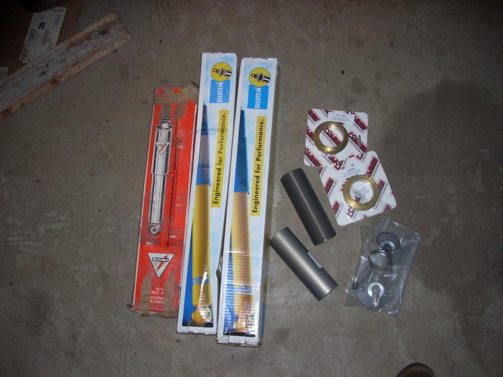
Posted by: jd74914 Dec 29 2014, 04:14 PM
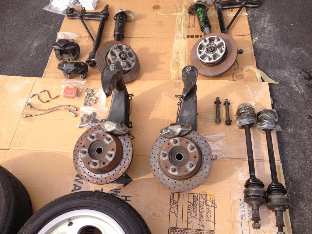
Then chuckc here had a great deal on some phonedials and the suspension to go with them so I just had to go 5-lug. Now the next trick will be raising the spindles on the Bilstein struts and selling the 4-lug raised spindle struts.
That's all I've got! Hopefully the next update will be in far less than a year! 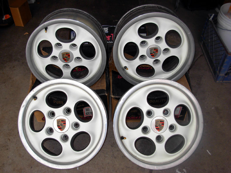
Posted by: Phoenix914 Dec 29 2014, 04:36 PM
That's all I've got! Hopefully the next update will be in far less than a year!
]I certainly hope so. This is just getting good!
![popcorn[1].gif](style_emoticons/default/popcorn[1].gif)
Posted by: jd74914 Dec 30 2014, 02:53 PM
I certainly hope so. This is just getting good!
I'll try!
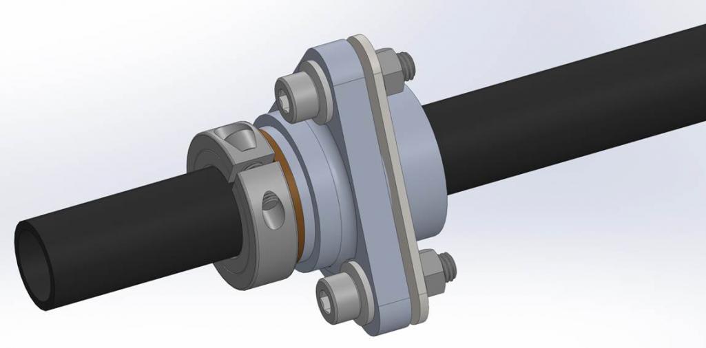
Quick exploded view of the new trailing arm inner features so they might make more sense (couldn't find the models yesterday night).
Posted by: Chris Pincetich Dec 30 2014, 03:35 PM
Curious about that trailing arm inner and your strategy for the end bolts. Are they torqued down super tight? Did you keep them "loose" and use locktite on the threads?
The reason I ask I my set-up, and it's propensity to get loose. I have an aftermarket roller bearing trailing arm pivot and it is secured on both ends by bolts like yours. They get a little loose, so I just re-tighten them....but soon will get in there to re-grease and rehab and likely coat the threads w some sort of locktite.
Great work and impressive math
Posted by: jd74914 Dec 31 2014, 11:36 AM
Curious about that trailing arm inner and your strategy for the end bolts. Are they torqued down super tight? Did you keep them "loose" and use locktite on the threads?
The reason I ask I my set-up, and it's propensity to get loose. I have an aftermarket roller bearing trailing arm pivot and it is secured on both ends by bolts like yours. They get a little loose, so I just re-tighten them....but soon will get in there to re-grease and rehab and likely coat the threads w some sort of locktite.
I'm planning on torquing them down normally and possibly using just a little loctite tape on the threads (and lot of anti-seize on the shank). I'd be a little afraid of using too much loctite because any corrosion also adds to the locking effect and it would be a shame to have to drill out big bolts.
One of the reasons I didn't like the needle bearing kits is that I couldn't see any way for them to allow misalignment on the inside ear. When you bolt the outer side to the piece that lets you adjust toe the bearing lines up nicely and won't cause any loosening if there is a little bit of bind. The ear is fixed however, and at least the kits I've seen didn't seem to have anything in there to allow for misalignment. I might be wrong, but I've always figured that the misalignment where wouldn't allow the bolts to stay tight or promote even thrust bearing wear. In my setup, the bolting point in the ear can pivot as it's a spherical bearing, so you're always bolting exactly perpendicular to the bearing if that makes sense.
I could be totally wrong, so take that with a grain of salt, but that was my rationale for going this way and not building with needle bearings. If this doesn't work I've been thinking I'll put a needle nearing setup together with misalignment washers to allow bolting perfectly normal to the thrust surface.
Posted by: FourBlades Dec 31 2014, 11:45 AM
Awesome job rebuilding the long! 
Lets see more soon.
John
Posted by: Mueller Dec 31 2014, 01:39 PM
Great progress.....
Have you considered using misalignment washers on the bolts?
http://www.jergensinc.com/site/product_detail.aspx?group_no=888
If you want to play with and experiment with a needle bearing for cheap, pay shipping and I'll send you an old unused Nadella bearing that was left over from when I used to make the kits.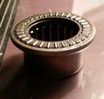
Posted by: yeahmag Dec 31 2014, 03:25 PM
Andy and I talked about this a bit. The problem is the misalignment washers are really quite thick. Would need to rengineer the kit to accommodate them.
Posted by: Jeff Hail Dec 31 2014, 06:58 PM
The inner ear will bend/deflect a little bit when adjusting toe. Trust me.
I like those pivot shafts!
Posted by: jeff Dec 31 2014, 10:52 PM
This setup should eliminate the bind when adjusting rear toe...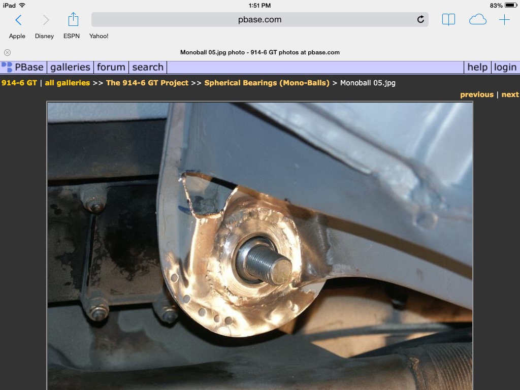
Posted by: jd74914 Jan 1 2015, 01:09 PM
Awesome job rebuilding the long!
Thanks!
If you want to play with and experiment with a needle bearing for cheap, pay shipping and I'll send you an old unused Nadella bearing that was left over from when I used to make the kits.
That would be awesome! PM sent!
Andy and I talked about this a bit. The problem is the misalignment washers are really quite thick. Would need to rengineer the kit to accommodate them.
Looking at it there really isn't much room in there unless you grind off part of the control arm not a bid deal, or recess the shafts into the arm.
I went this way mostly for cost since everything is new anyways. Even good spherical bearings are pretty cheap compared to the Nadella rollers.
The inner ear will bend/deflect a little bit when adjusting toe. Trust me.
I like those pivot shafts!
Interesting...I wish I had looked more closely when pulling everything off. Thanks Jeff! I'm hoping I can pull this off with a level of quality near your car's!
This setup should eliminate the bind when adjusting rear toe...
Yep, mine is quite similar to that on the frame side. used bearing cups from UB Machine because I didn't really feel like machining customs ones. The main difference between that setup and mine is that I didn't weld threaded bushings straight into the trailing arm and instead pressed in an assembly to ensure co-linearity.
Posted by: jd74914 Jan 9 2015, 07:05 PM
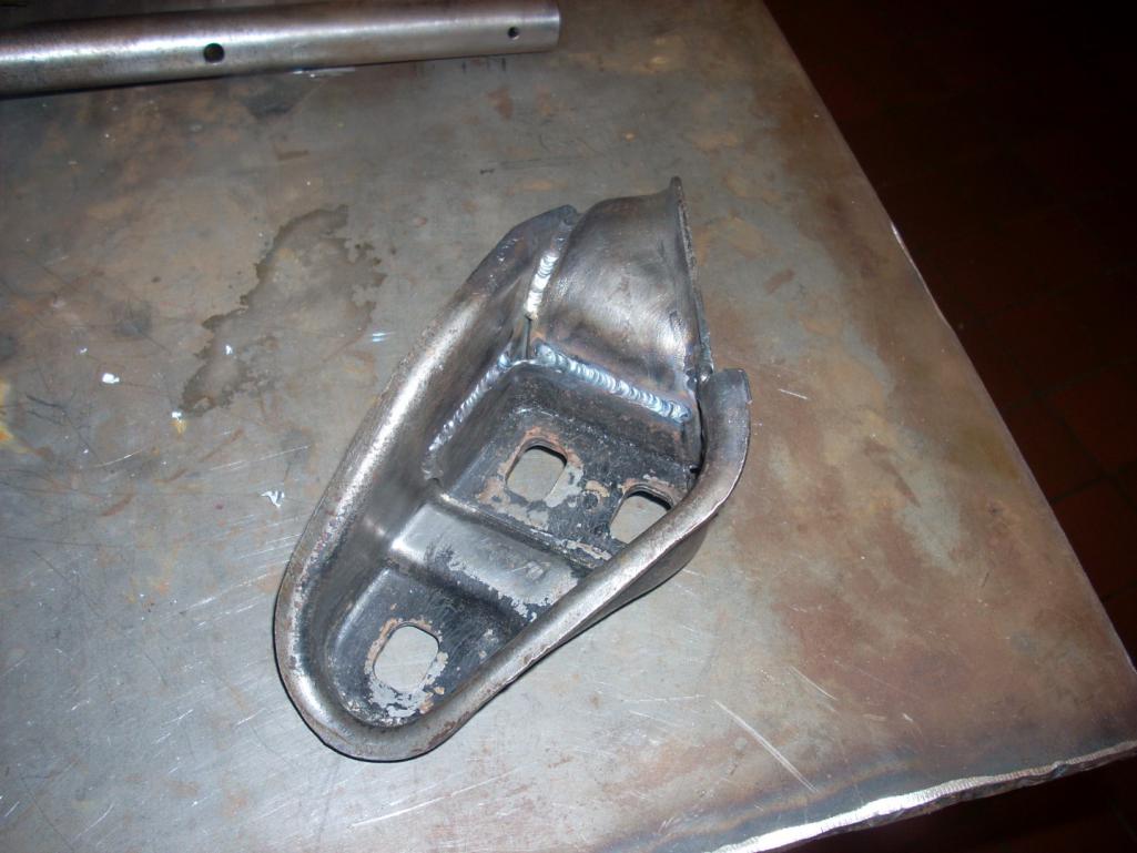
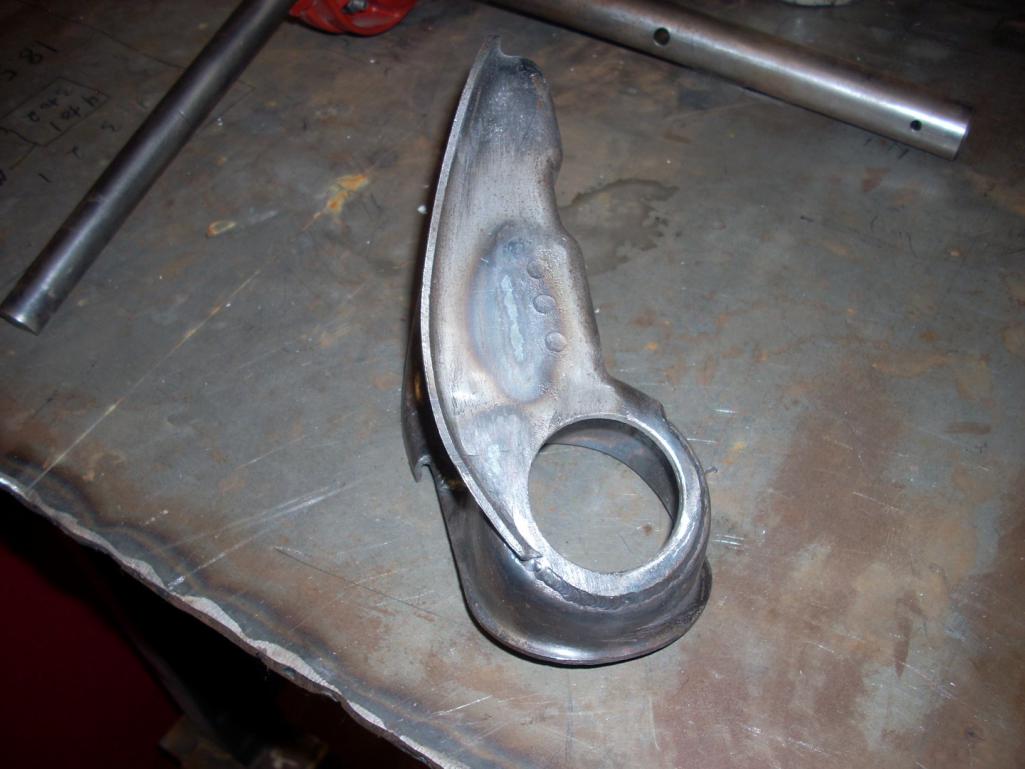
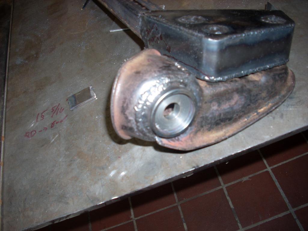
A few more pieces. I seam welded the trailing arm mounts and then machined 1.75" holes in them for my spherical bearing housings. I screwed up on the first one by not machining an insert to help it hold shape with all of the heat and warped it a bit which required a little honing. After making that mistake I turned an aluminum piece to pull heat out of the housing which seemed to work well. We'll see how the slightly out-of-round housing works out. The bearing pressed in OK, but I think I might make another one since we don't have a shortage of suspension mounts.
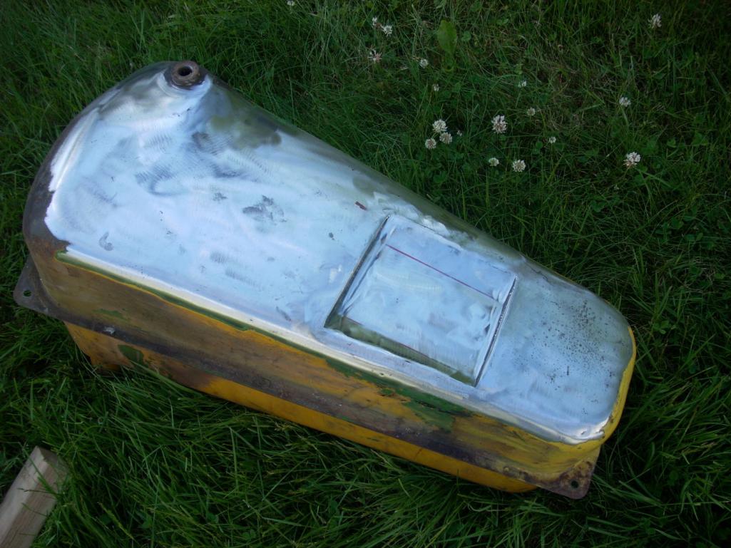
Unfortunately the final product picture is blurry, but I think you can get the idea. I just found the last picture and thought it was cool so I added it. It's of the bottom of the gas tank in a '58 John Deere 420C bulldozer which I clearanced to fit a taller battery for Father's Day. 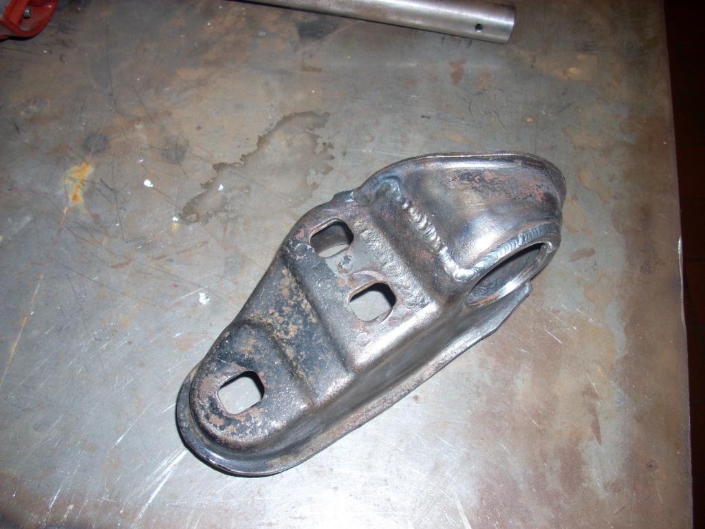
Posted by: jd74914 Jan 9 2015, 08:17 PM
Forgot to add this in the last post...
Those trailing arm brackets are really tough stuff. I'm guessing they are made of 41xx series steel since I tried cutting one pretty slowly with a hole saw and wasted the hole saw even using lots of oil. Mild steel parts don't tend to do that. A carbide cutter on the mill worked much better. For anyone thinking of seam welding them they also weld really nicely (definitely cold rolled)!
Posted by: veekry9 Jan 9 2015, 08:46 PM
I missed this thread last year as I was off on other pursuits and have just now discovered this build.
We were/are using the sls technique to create lost foam patterns for small production runs of exotic metal castings.
The FormulaSAE racer is a jewel,well done. The pertinent specification of interest to me was the torsional stiffness of the chassis.
Now the arduous journey begins,the sheetmetal repair of the 914 and the skilled application of lightweight reinforcement.
Q
The longs themselves were redesigned and made taller with slightly different metal thicknesses/layering. This was done to increase the vertical moment of inertial and improve the car's bending stiffness in this area. From a design perspective, the new geometry (more or less 0.5" taller with some strategically sized metal thicknesses) results in a 246% bending stiffness improvement over stock with a stiffness/weight efficiency (in terms of moment of inertia/cross-sectional area) of 4.927e3 mm^4/mm^2 vs the stock efficiency of 4.042e3 mm^4/mm^2. Overall weight increase is about 27 pounds. For reference the Engman kit (best as I can tell since I haven't held one) weights 18 pounds and increases stiffness by 168% assuming an OEM long to start with.
You'll note that it will still be double layered with the corrugated inner. The insulated heater tube was removed and a solid tube put in its place. This might get used as a wire tray later. Anywhere there are butted seams there is also a backer lap joint.
Q
Yeah,this is what I like,the deepening of the cross section of the longs,the use of corrugated rather than flat sheetmetal panels.
That you are placing them internally is brilliant and never occurred to me,looking from the outside of my pristine longs.
I'm going to use that idea as it's a great solution to the flexi flyer characteristics of the floorpan.
A stiff perimeter monocoque ala 904,not outside the box,inside.Terrific.
Some of this may be of interest to you as no doubt you're proficient in the use of cae software.
https://www.rhino3d.com/
http://www.cimsystem.com/
http://www.mastercam.com/en-us/
http://www.caelinux.com/CMS/
Posted by: jd74914 Sep 14 2015, 07:46 AM
Finally did a little more work this weekend after a long hiatus with a lot of work, an almost move to KY, and a bunch of other people's projects in between.
I've been spoiled by working on cars that don't require welding or painting upside down and decided to build a rotisserie to reduce the amount of overhead welding on all of the suspension mounts. This time around the whole bottom will be stripped, repainted, and undercoated which will also be nicer to do on a side. My goal is to make a quick and dirty one to not take much time away from the overall car build so I'm modifying 2 cheap engine stands to do the job. They don't have pivot bearings so hopefully the car won't be too hard to turn, but I guess I'll cross that bridge in a few weeks when loading it on.
To try and avoid having the longest car build ever I'm trying to spend at least half a weekend day per week working just to make a little progress.
--------
First step was to cut apart the vertical leg, add about a foot of metal. This results in a pivot-to-bottom brace height of 38", giving about 3" of safety factor from the widest point of the car to brace. The pivot also needed to be made parallel to the bracing as the engine stand was tilted non-parallel. Next was to repeat the modifications on the second engine stand leg. After a whole bunch of hack fixture and a bit of welding the second stand was done too. Note that (2) pieces of 1.375" square x 0.1875 wall steel were used since I didn't have any of the correct 1.5x3x0.100" box beam. It should be plenty strong enough for a light car though. 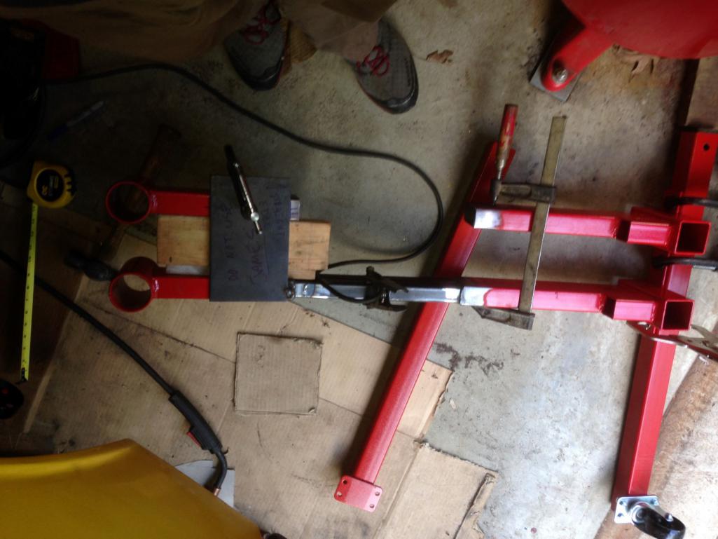
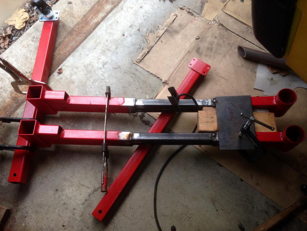
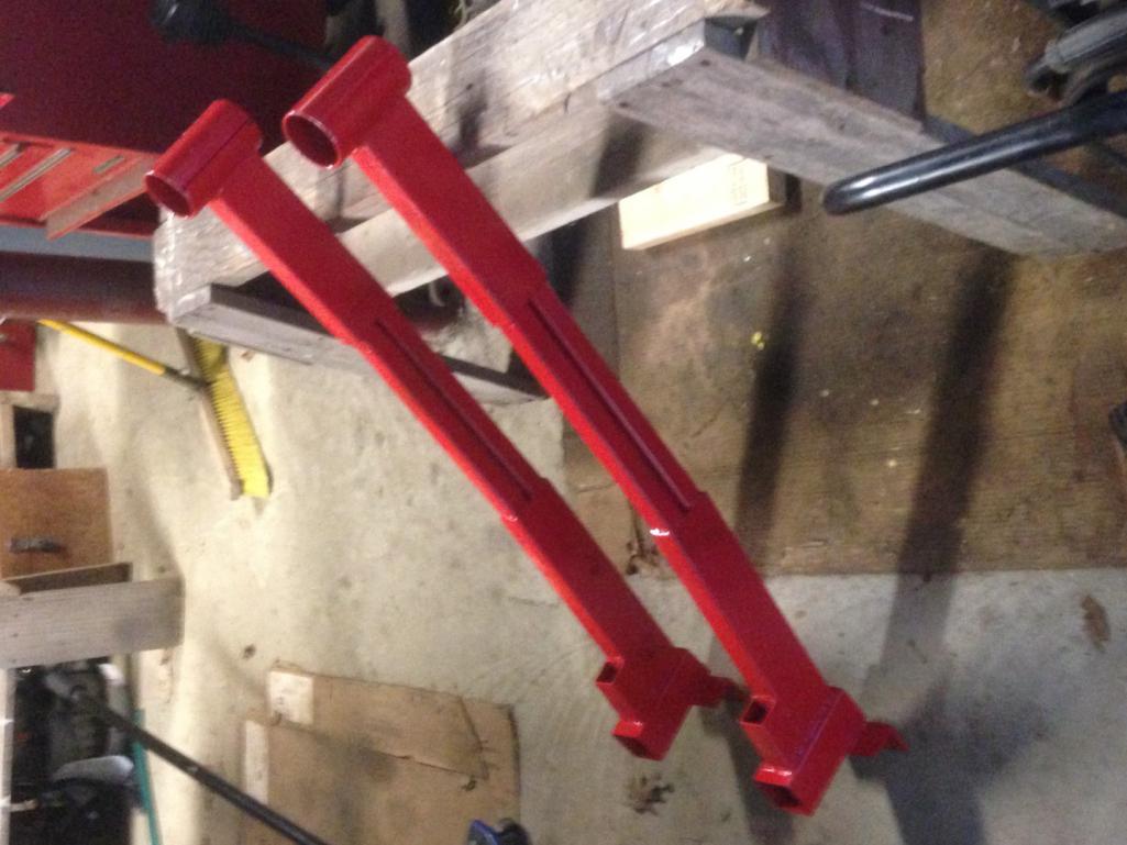
Next week's goal is to get metal to make the arms to attach to the bumper mounts, some cross bracing, and connect the 2 stands under the car.
Posted by: jd74914 Oct 31 2016, 06:37 PM
October 2016 Update:
Not much got done this month due to school commitments. I did get time to clean off the car and start organizing parts. Yesterday I also got the intake manifold assembly off of the LGT motor, removed the TGVs and started removing all of their parts in preparation for gutting them. I'm going to be removing the throttling valves and welding up the throttle shaft ports in the coming weeks. Pictures coming soon.
This picture is stolen off the web, but essentially the end goal of the TGV delete.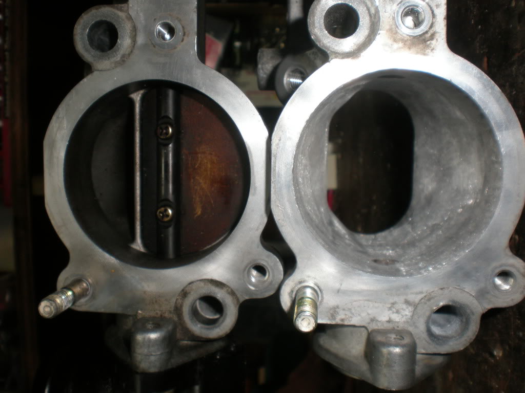
Additionally, I started designing the mounts and arms for the new sway bar. It's a NASCAR bar from HRP. Before deciding on the final arm length, I wanted to check the effective installed motion ratio to understand at what point further adjustment is useless. Some initial basic calculations indicate that an 8" arm length is enough, but the actual travel math is relatively complicated since the control and bar arms move in different planes. To solve this I added the bar into my suspension kinematics model, but unfortunately the effective motion ratio is a bit harder to pull out than I thought it would be. Results TBD. 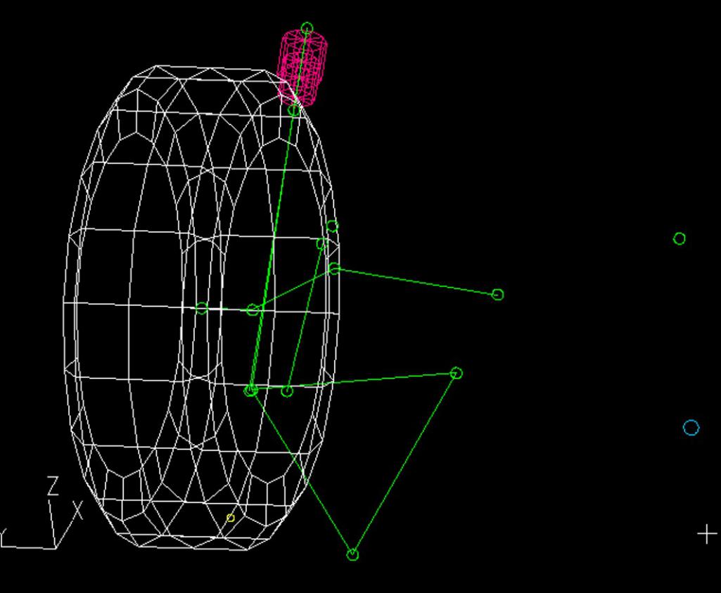
Posted by: jd74914 Nov 12 2016, 05:18 PM
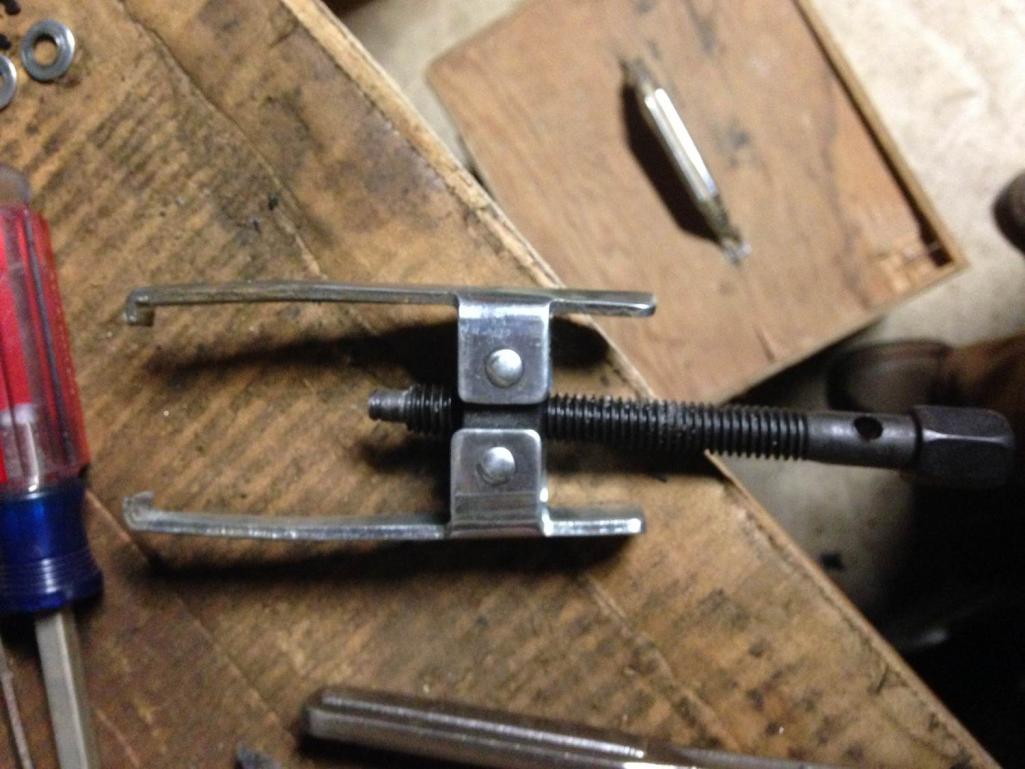
I picked up a gearbox off Craigslist this week. It's out of a 2012 WRX and has ~30k miles (the car was wrecked). It bench shifts smoothly and is super clean so I'm hoping that it isn't messed up inside, but I guess we'll see when the center diff comes out. 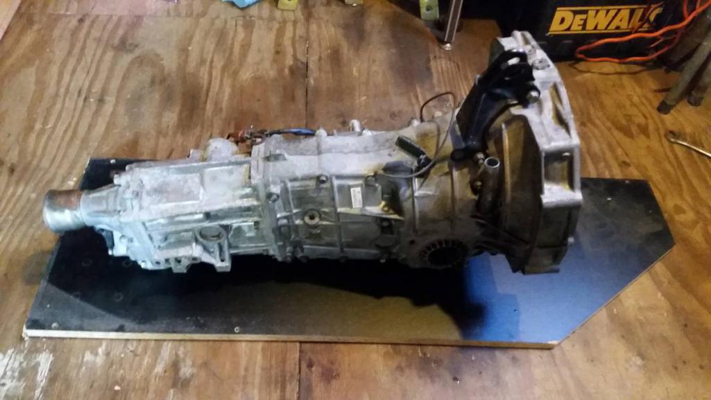
I've got feelers out now for a broken central diff in the local area so I don't have to ruin this one making a locker if it's in good shape. Good ones seem to go for $200-350 on NASIOC so selling this one would go pretty far in offset the overall transmission cost. Anyone here have a broken diff they'd be willing to let go for cheap? 
The 2008-2014 WRX transmissions seem to be pretty stout units. Some threads on the Subie forums show their gear widths are greater than the early WRX transmissions and the case castings seem to be a little beefier too. Unfortunately, around here at least they are a bit more expensive than the older push-clutch Legacy, Impreza, etc. stuff. Right out of the box the gear ratios appear pretty well matched, though even with the 3.900 front diff first gear seems a little bit low. Ideal 1st gear is from an STi RA but those gears/main-shafts are super rare and priced accordingly.
The plot below shows tractice force, or the actual power put through the tires into the ground, vs. vehicle speed for the 08-14 WRX transmission. It assumes a perfectly stock '05 Legacy GT power output (shown in the second plot). In terms of pure acceleration and drive efficiency, you want this curve to have a parabolic shape. The parabolic shape means that power to the ground is constant and at its maximum. As mentioned before, 1st is a little bit low, but it's going to stay that way forever probably. The easiest way to make the in-gear traction numbers fit the overall traction parabola better is to shift the engine powerband up slightly and increase torque in the 4100-4600 rpm range. With some AVCS and boost tuning this shouldn't be too difficult. 
One other thing to note is the red "max tractive force" line. This line is the most force the tires can handle and still retain traction. It's a pretty simplistic calculation just using CG, wheelbase, and an assumed single tire coefficient of friction which then calculates dynamic driving wheel weight and from that max sustainable tractive force. The number isn't correct since I'm just guessing CG, weight, etc. The tire friction coefficient is pretty questionable since I've never seen one for street tires (only slicks) and the fact that it's not taking into rotation speed or any lateral forces added by the suspension kinematics. It is useful to basically know first gear and the start of second are really just for burnouts!
The spreadsheet used for these calculations is attached is anyone wants to play with it. No guarantees on accuracy, though I believe everything is correct. The format was borrowed from something posted a long time ago on Pelican Parts by B. Smith (IIRC, unfortunately I never wrote down the source), but has been modified extensively. You can add different gear ratios in, I just only put in some common stuff. Check out the last page for some Subaru transmission information if you want to play around with different gears not listed in the list or personalize it to your transmission. 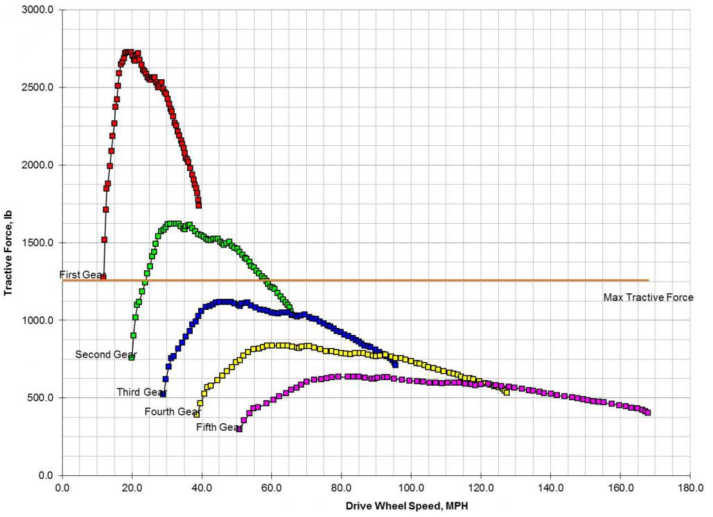
Stock dyno plot (not mine, just from a local eddy current dyno)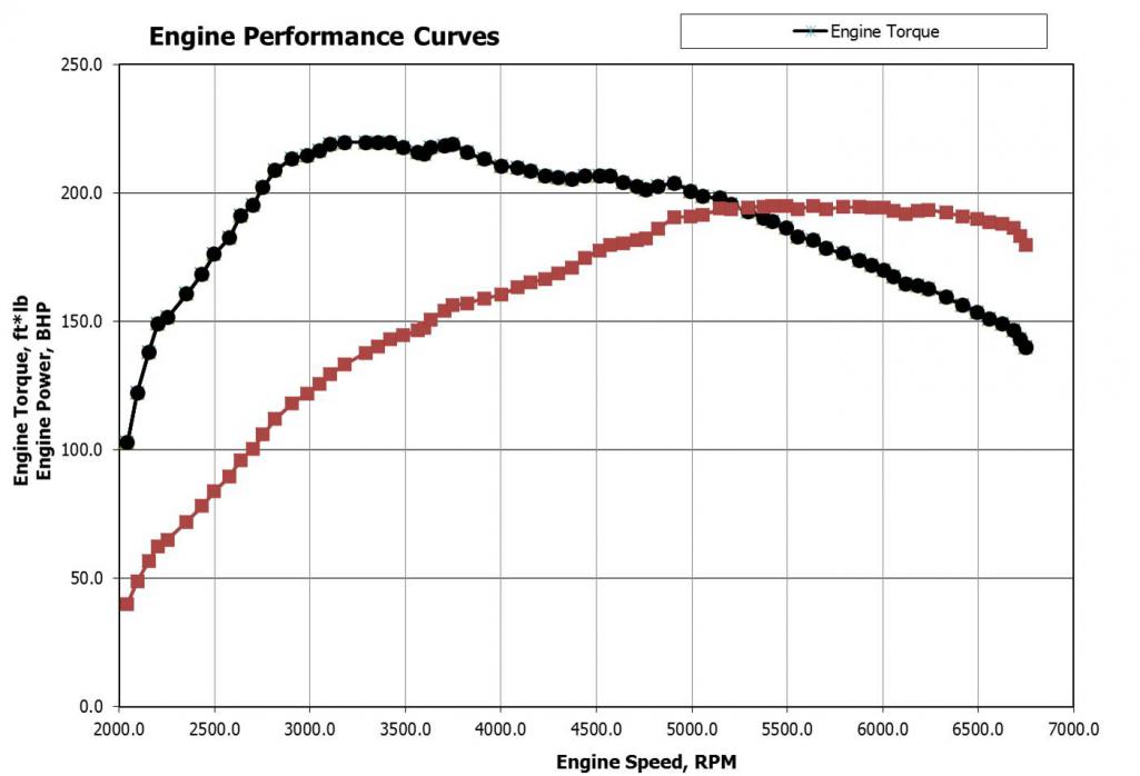
Posted by: jd74914 Nov 12 2016, 05:22 PM
Ok, I guess the spreadsheet add doesn't work for .xlsm
It's attached in a .zip format so anyone who wants to try it will have to unzip it before using.
Attached File(s) PORSCHE_914_SUBARU_DRIVETRAIN_CALC_A.zip ( 1.32mb )
Number of downloads: 43
PORSCHE_914_SUBARU_DRIVETRAIN_CALC_A.zip ( 1.32mb )
Number of downloads: 43
Posted by: 914forme Nov 13 2016, 06:21 PM
Additionally, I started designing the mounts and arms for the new sway bar. It's a NASCAR bar from HRP. Before deciding on the final arm length, I wanted to check the effective installed motion ratio to understand at what point further adjustment is useless. Some initial basic calculations indicate that an 8" arm length is enough, but the actual travel math is relatively complicated since the control and bar arms move in different planes. To solve this I added the bar into my suspension kinematics model, but unfortunately the effective motion ratio is a bit harder to pull out than I thought it would be. Results TBD.
really love what your doing but over complicating it a bit. The distance front the bar center to the center above the A-Arm is your ideal location since th pivots move in multiple plains. Then you are "stuck" with the number of degrees the amounts will allow your bars to travel with out binding over the range of the suspension. two points in a cad drawing will not tell you that, real world will. This of course is based on the factory U tab on the arms, and a double sheer tab up top running a set of rod ends for the drop links. If you are using a spherical bearing on the arm, or a different high angle mount, then your movement can be greater.
Looking forward to seeing your solution to the Nascar bar mounts. I know I gave lots of thought to mine before I said
 and just did it! Best solution
  I do know they do not bind with bar rotation.
Posted by: jd74914 Dec 20 2016, 10:46 AM
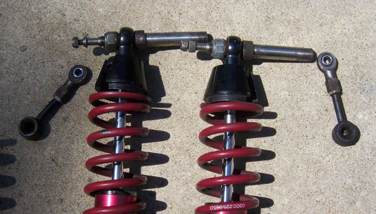
I got a sweet set of single adjustable JRZ shocks for the rear from Stephen (914forme).
They take 2.25" springs-my old shocks took 2.5" so I'll need to get some new springs. The rod-end spring perches are pretty nice in that they fit to the eyelet. The trailing arm attachment bolt is a pretty nice piece as well. These should work well with the raised "stock" shock console I'm planning.
Notes for later: Perch thread dimension is said to be M52x1.5. That is incorrect because the major diameter of the threads is ~2.1565 vs 2.046" (51.97 mm) it should be for that thread. 
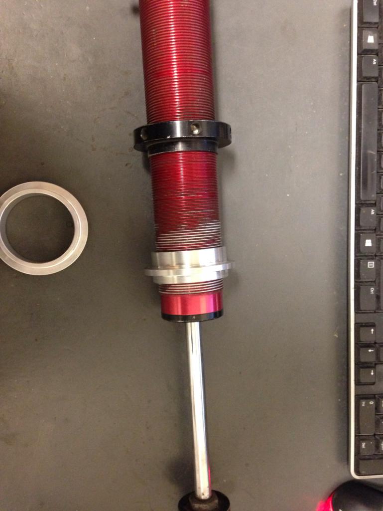
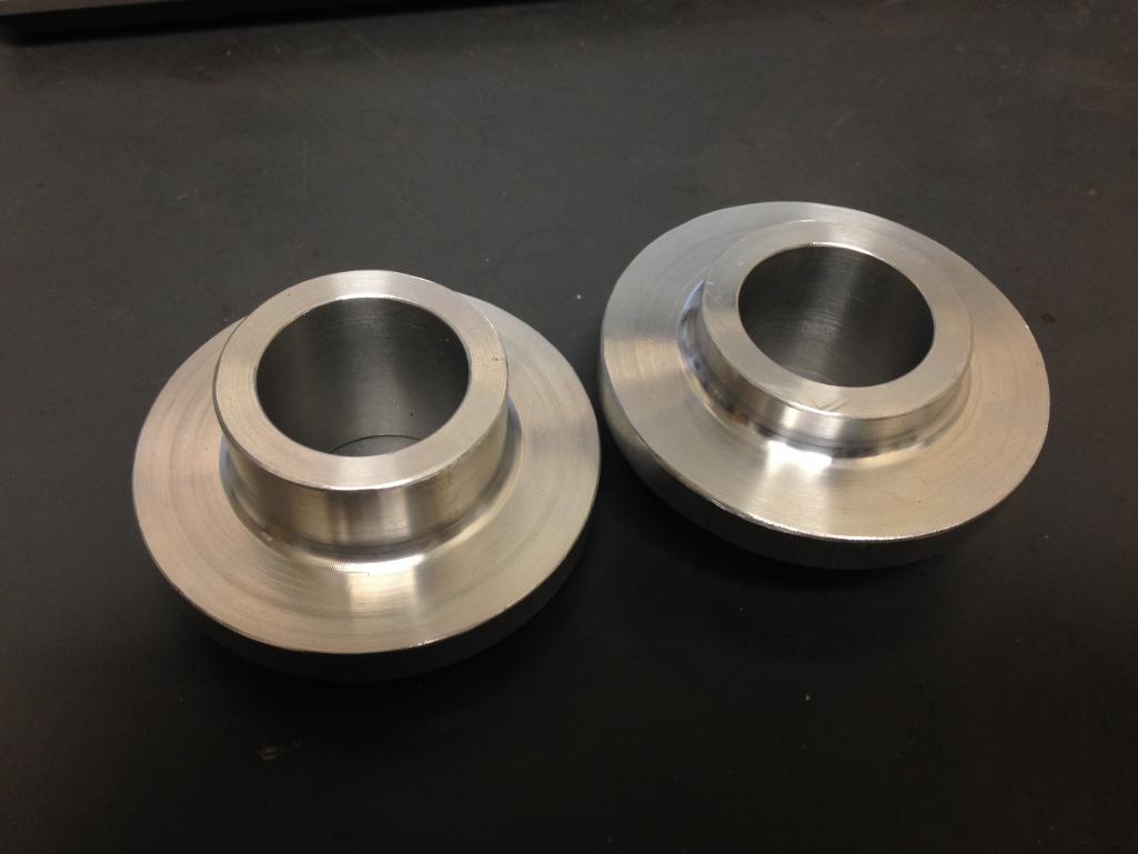
This morning I turned down some 6061 spring spacers so I can run a zero-weight helper spring and avoid having the main spring come off the perches when the car gets jacked up. The smaller lip is for the helper spring and larger for the main coil. These are going into the pile for anodizing now.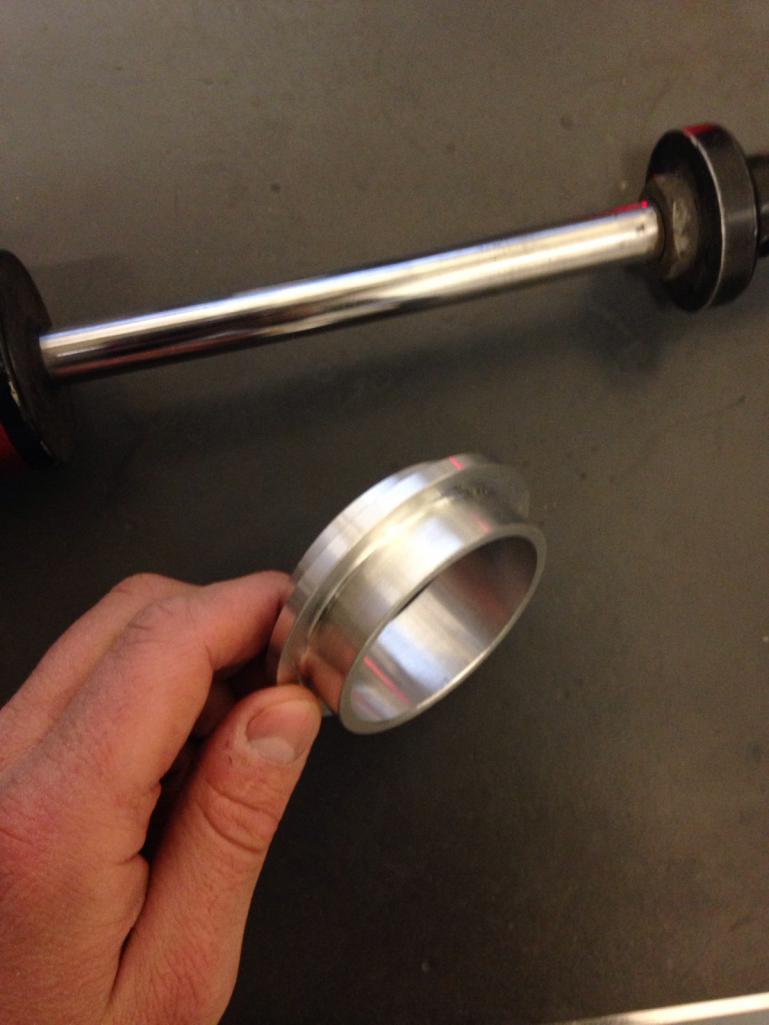
Posted by: jd74914 Dec 20 2016, 11:10 AM
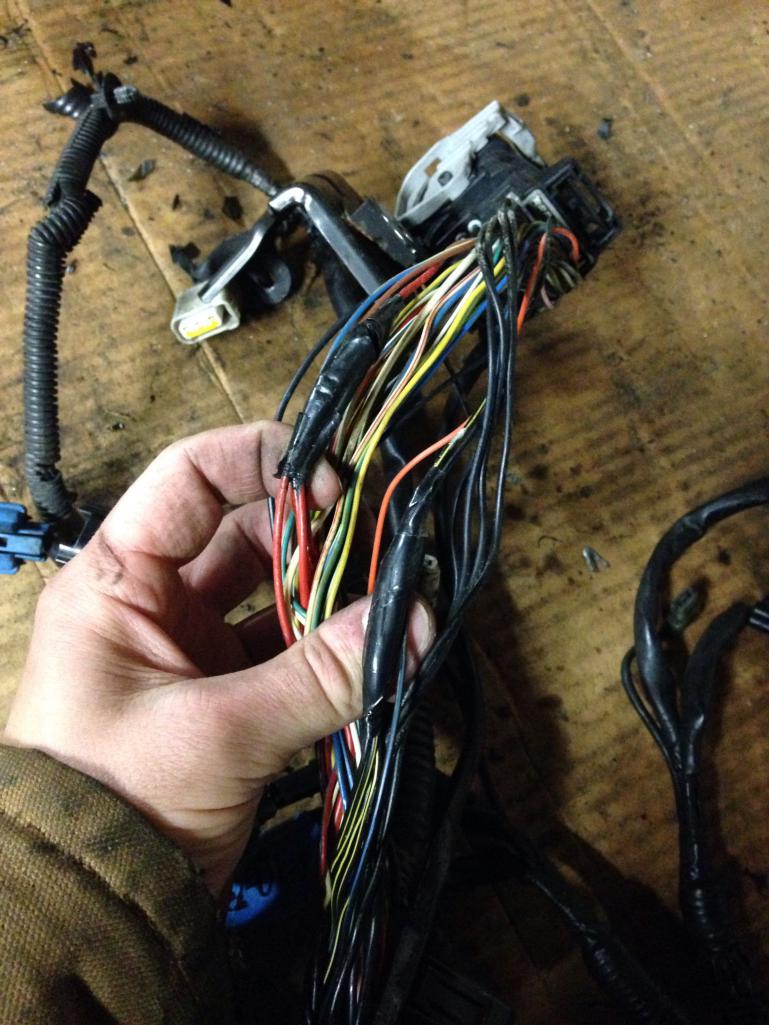
Also pulled the intake wiring harness off. With all of the zip ties and hard to get to connectors, it was a bit of a pain. I didn't take a picture, but this car doesn't have a MAF installed (thought all of these did...need to do some more reading there), but did have the associated connector and a pretty slick sealing blank on the loom.
It contains most everything (engine-wise) besides the camshaft phasing controls (AVCS), crank position sensor, and coil driver wires. I was expecting the harness to be perfect given it came off a motor only 11 years old , but it had some issues. It looks like someone has been into it before and cut/spliced some wires. Its a little strange since they didn't make any changes; perhaps they were trying to do some troubleshooting and didn't have the correct probes.
Next step is to identify all of the connectors and reverse engineer the harness to start building a new one. The plan is to build a separate intake and engine block harnesses with firewall bulkhead connectors for fast engine removal. We'll see how that works out! 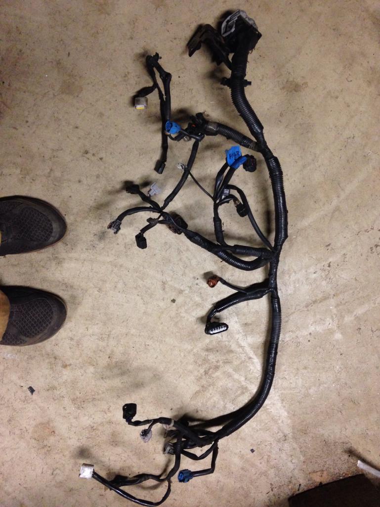
My cheap NASCAR expansion tank arrived. Buying a used tank was cheaper than buying the nice almost-but-not-quite hemispherical tube caps, so I went for it. It'll go nicely with the NASCAR bar. I'm pretty stoked to weld on some mounts, loose the lower wiggins fitting, and go to town with it. 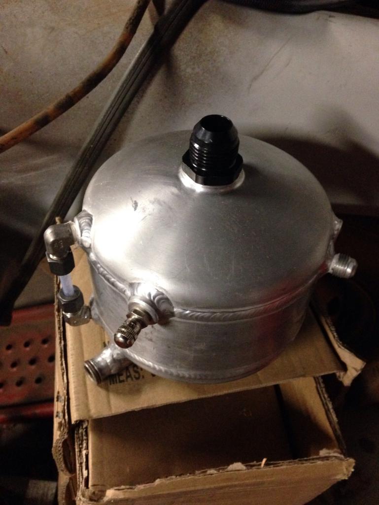
Posted by: 914forme Dec 20 2016, 12:24 PM
I got a sweet set of single adjustable JRZ shocks for the rear from Stephen (914forme).
This morning I turned down some 6061 spring spacers so I can run a zero-weight helper spring and avoid having the main spring come off the perches when the car gets jacked up. The smaller lip is for the helper spring and larger for the main coil. These are going into the pile for anodizing now.
Nice job on the spacers.
Posted by: jd74914 Dec 22 2016, 04:59 PM
Nice job on the spacers.
Thanks! Spending lunch turning spacers to save $50 for other stuff seemed worth it.
Posted by: jd74914 Dec 22 2016, 05:22 PM
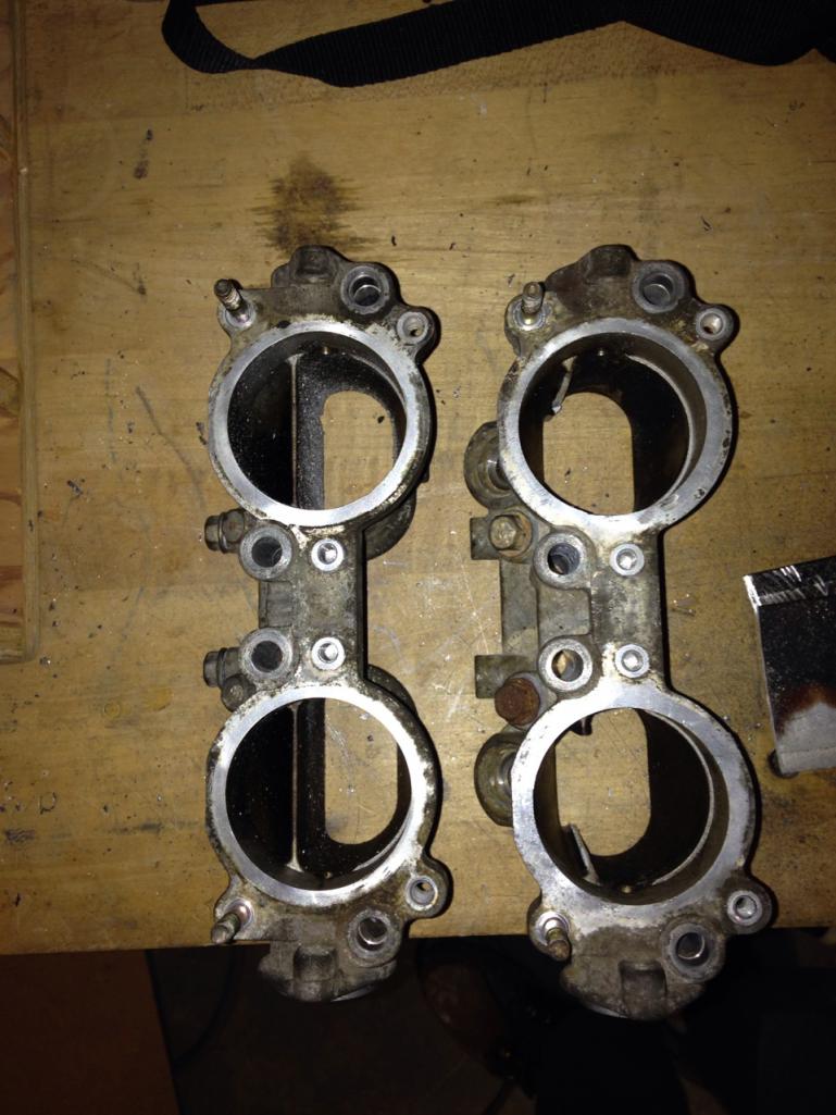
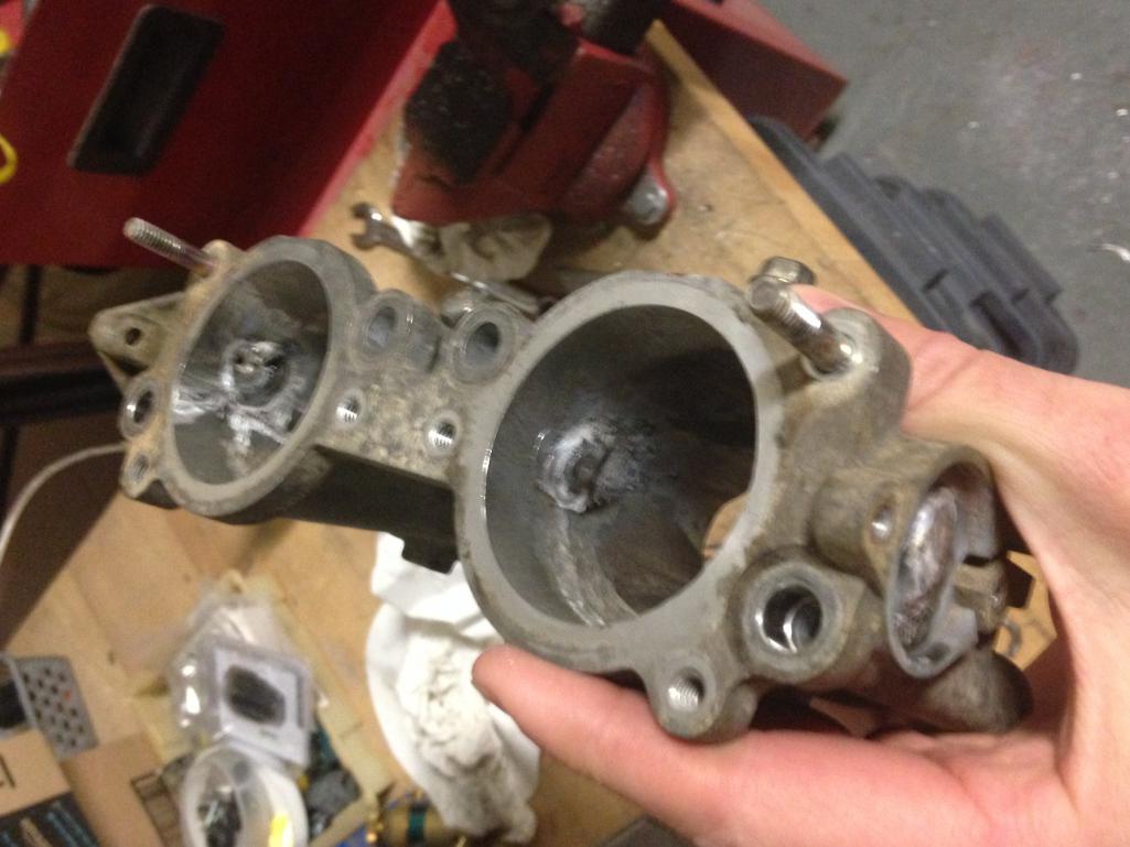
Next up are some TGV deletes. I really just started going through these so I could reduce the I/O on my ECU, not so much for any huge power gains. A bunch of companies sell nice milled versions for not too much money considering the machining complexity (IAG ~$300), but I'm way to cheap to buy them so I decided to do them myself. A lot of people just remove the butterfly valves like in the first pictures below, but given the difficultly to remove it seemed worth it to tally delete the crossbars and smooth the lip the butterfly sits on when closed.
Note: theoretically, the engine probably won't run as well at low revs (especially while cold) with these deleted. When closed they basically reduce the size of the runner dramatically to increase the velocity of flow hitting the injection stream. The increase in velocity would result in increased droplet entrainment, or better mixing. The fuel jet is essentially a jet in crossflow so increasing crossflow (runner) velocity decreases the momentum ratio of the injector stream and should cause it to bend over and not hit the back wall as hard.
To delete you basically just:
1) Remove the TGV assemblies-easiest if you first remove the fuel rail
2) Remove the butterflies. Easiest way is to drill out the peened back side of the screws and then use an impact screwdriver on the front. Otherwise you can also just drill out the screws all together.
3) Remove all of the hardware (actuator, position sensor, etc.)
4) Tap out the shaft
5) Use a hacksaw to cut the "cross brace" as close to the inside surface as possible
6) Pick up your favorite die grinder and flame burr and go to town on the remaining brace. While you're at it you might as well smooth the butterfly plate lip. It's easiest if you mount in a vice and then use some beeswax, cutting oil, or machine coolant on your burr so it doesn't gum up.
7) Weld up the shaft holes.
8) Grind welds down smooth and go over whole interior with sanding wheel.
9) Clean up whole TGV body and reinstall (or whatever)
I'm only up to step 6 so far-didn't have time to borrow the TIG during lunch today. Hopefully I'll get there next week.
Disassembled on the bench (4):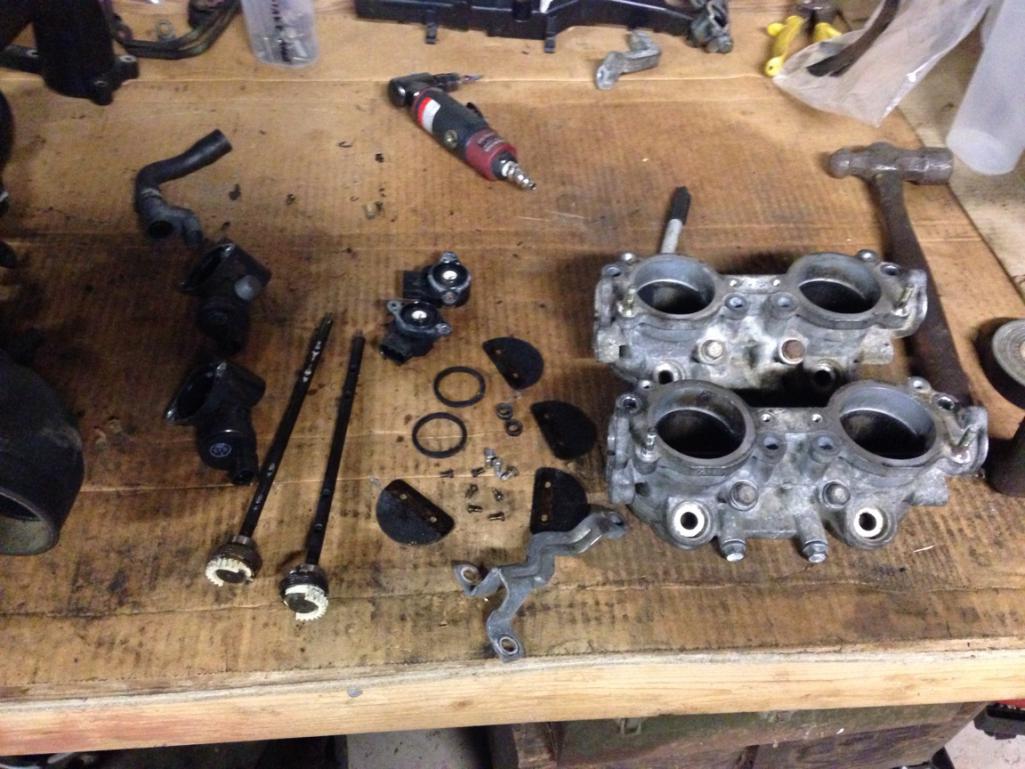
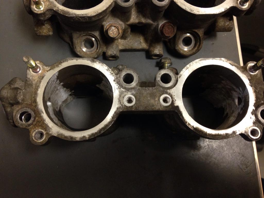
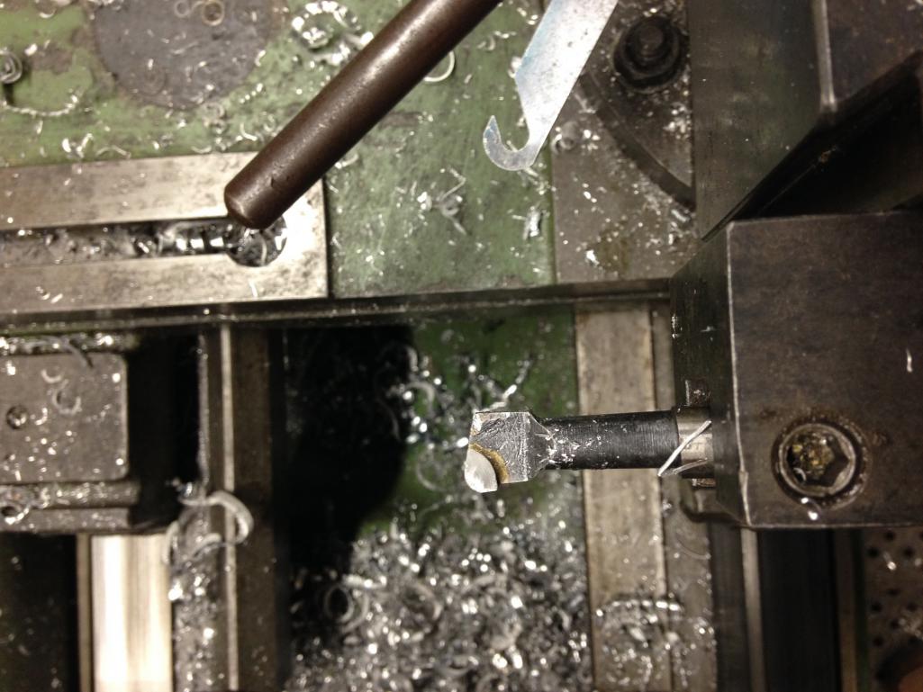
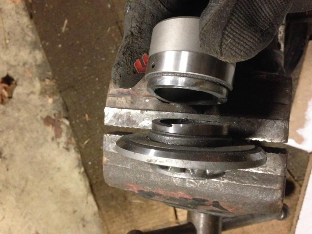
Shot of the cross brace inside before cutting and comparison after cutting (5).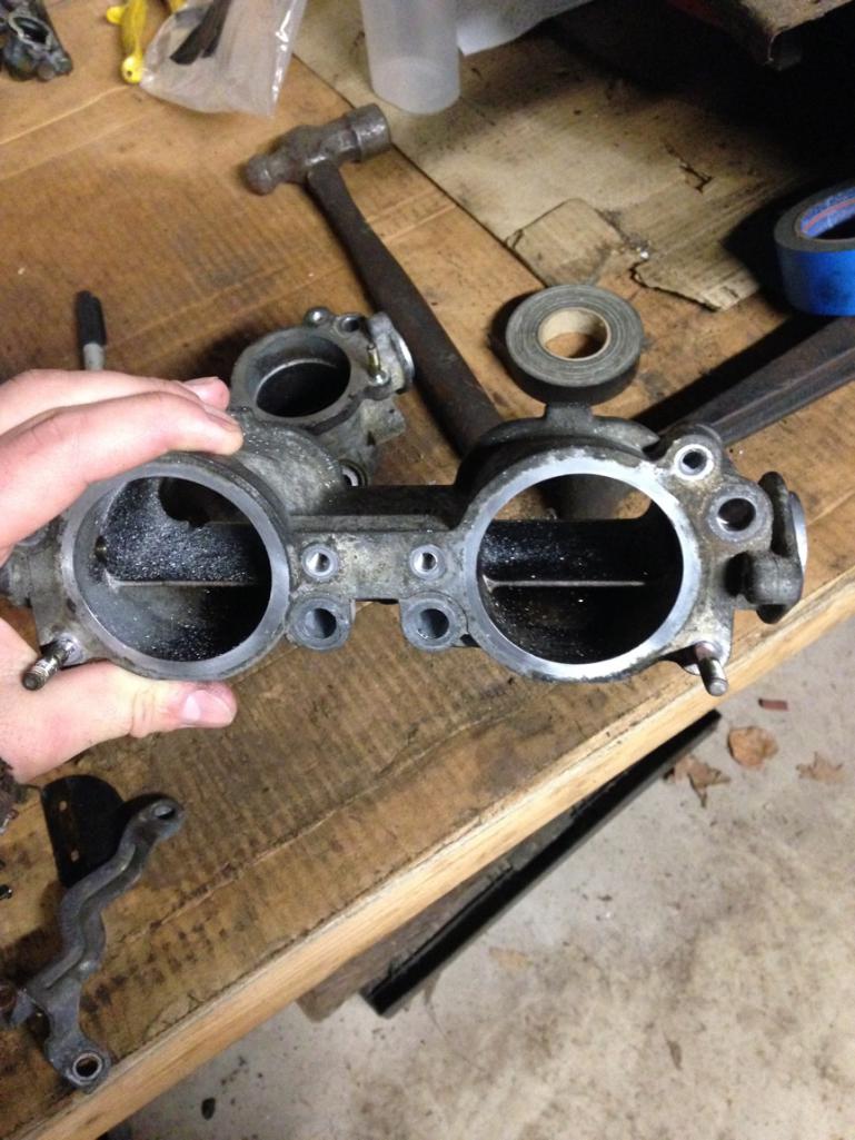
You can see the little lip mentioned in (6) on the opposite side of the TGV interior as the cross brace.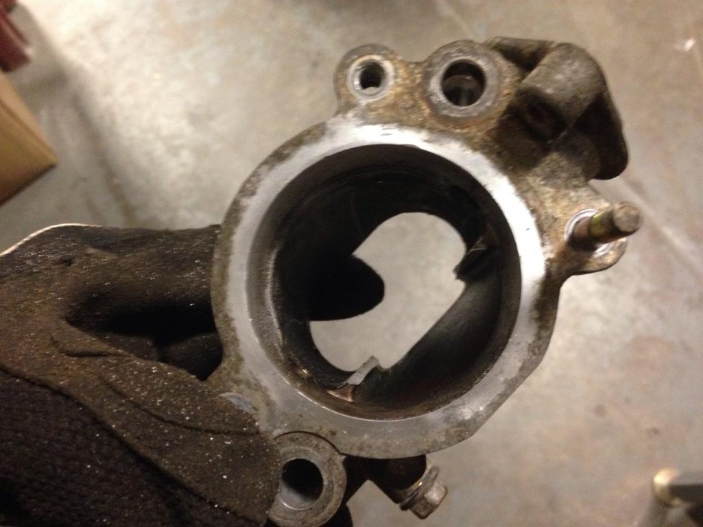
Mounted in the vice after some grinding (6).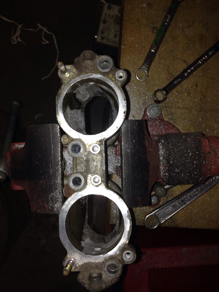
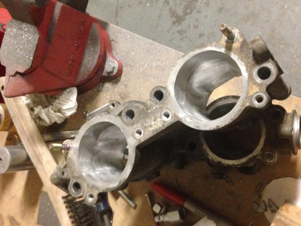
Posted by: jd74914 Dec 22 2016, 05:26 PM
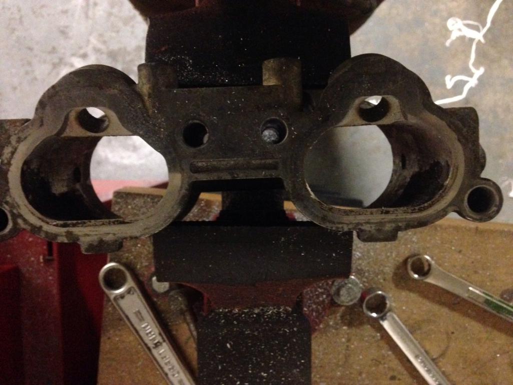
Another view of the material taken out with slightly better lighting.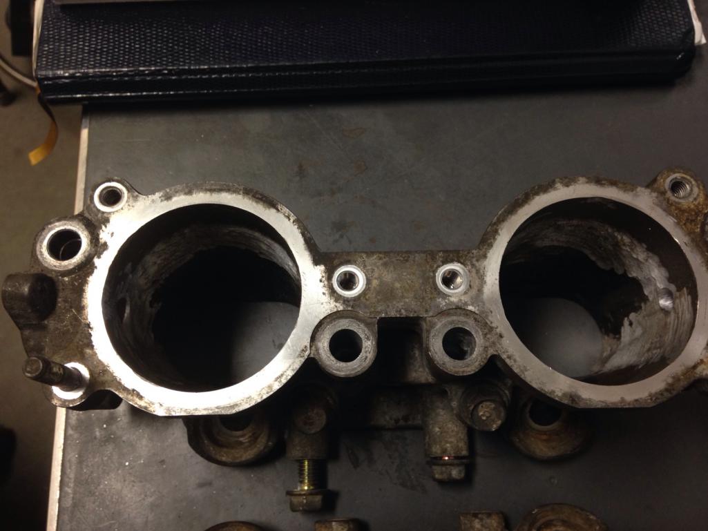
The last step is to weld up the shaft holes and do a bit of sanding to remove any small gouges left from the die grinder. The shafts do ride on plastic bushing which are pretty easy to grind out with the grinder (I couldn't get them out by hand, not sure if that's typical or not). I'm probably going to blast these too to try and get rid of some of the oxidation and then paint or something to keep them nice. 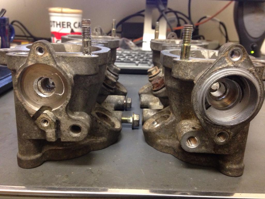
Posted by: jd74914 Dec 29 2016, 11:53 AM
really love what your doing but over complicating it a bit. The distance front the bar center to the center above the A-Arm is your ideal location since th pivots move in multiple plains. Then you are "stuck" with the number of degrees the amounts will allow your bars to travel with out binding over the range of the suspension. two points in a cad drawing will not tell you that, real world will. This of course is based on the factory U tab on the arms, and a double sheer tab up top running a set of rod ends for the drop links. If you are using a spherical bearing on the arm, or a different high angle mount, then your movement can be greater.
Looking forward to seeing your solution to the Nascar bar mounts. I know I gave lots of thought to mine before I said
and just did it! Best solution I do know they do not bind with bar rotation.I'm planning on running a high misalignment rod end on the arm-side to gain a bit more travel. That said, as angle increases the force applied to the arm increases tremendously, so buckling can become a concern. I still haven't gotten a change to measure everything yet so we'll see.
The mounts will look similar to OEM mounts. I wanted to keep the mounting geometry the same so I'd be easy to align and let me use the stiffening plates from MADDOG. The big difference is that instead of the OEM bushing, I'm going to use a Frelon-lined flanged sleeve bearing. These are self-lubricating and are supposed to last well in dirty environments but that's something driving will need to validate. The bar certainly spins well in them!
The CAD views are below (drew it up to check some clearances before making chips and buying fasteners). I'm going to machine first thing next week when my metal comes in (6061-T6). They are a bit beefy, but I really didn't want to risk HCF cracking after a few years of use and exposure to sand/salt. The gap you see between the bushing mount and backing plate is ~0.110 to account for inner fender and stiffener thickness.
Posted by: 914forme Dec 29 2016, 12:32 PM
Nice design
Posted by: jd74914 Dec 29 2016, 04:18 PM
Nice design
Thanks! Hopefully it works ok...
The bushing is nearly centered on inner fender to try and minimize any cantilever action (like the stock setup) from slight misalignment across the car. Not sure if it'll do anything, especially given the addition of the inner fender doubler, but it seemed like it couldn't hurt.
Posted by: 914_teener Dec 29 2016, 04:34 PM
Interesting...gosh I wish I had the toys and tools at my work....and the time.
I put the split ring retainer on the inside of the fenderwell....quess I could have put it on the outside....don.t see why that wouldn.t work.
Posted by: jd74914 Dec 29 2016, 05:44 PM
Interesting...gosh I wish I had the toys and tools at my work....and the time.
I put the split ring retainer on the inside of the fenderwell....quess I could have put it on the outside....don.t see why that wouldn.t work.
Yeah, I'm pretty lucky.
By virtue of being in grad school, I effectively have all 60++ hr work weeks, but I've been trying to use small downtime to make stuff lately to get this thing done. The really nice thing is that in addition to having access to a lot of machinery we have two really skilled machinists who enjoy teaching. I'm only putting the collar on the outside so the bar and bushings can be pulled without tank removal. Inside would certainly make for a cleaner install.

Posted by: 914forme Dec 29 2016, 06:33 PM
Collar on the outside it is a functional piece not aesthetics.
BTW, Mine using a standard spherical bearing and mounts found on ag equipment. They are dirt cheap and handle misalignments very well.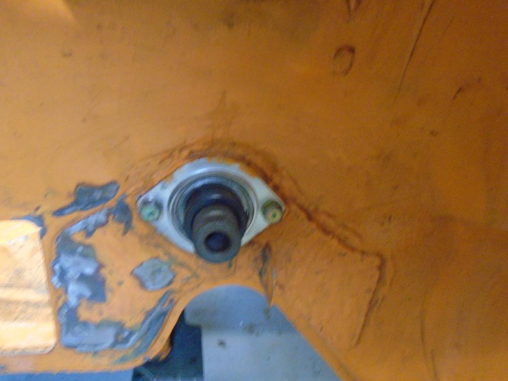
Collars lock them in place on the outside.
I changed the arms to be double shear this year, will see how it works.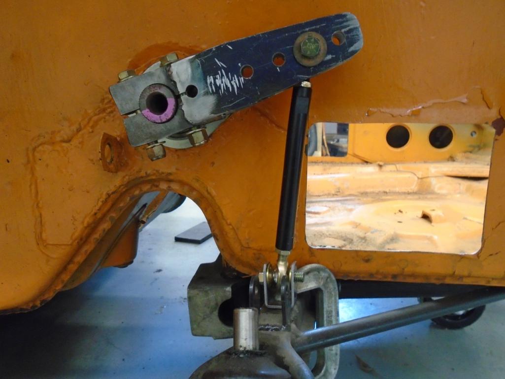
Great idea, soaking up all the machining knowledge you can. Always good to know how stuff is built.
Posted by: jd74914 Dec 29 2016, 07:19 PM
BTW, Mine using a standard spherical bearing and mounts found on ag equipment. They are dirt cheap and handle misalignments very well.
I changed the arms to be double shear this year, will see how it works.
Thanks for the pictures! Yeah, those flanged sphericals are pretty nice. If these don't work well I'll go that route. It's easy enough to swap.
The double shear arms are much better than single shear. I have a set of aluminum arms from Speedway (like 18 inches long now
) that will be cut down. I'm trying to figure out how to put them in double shear. It seems preferable even if it requires an additional piece and fastener. Are you using 5/16" or 3/8" rod ends?
Great idea, soaking up all the machining knowledge you can. Always good to know how stuff is built.
Yep-just shooting for a more holistic education, especially since it's likely that I'll never have access to the same resources in any future jobs. The unfortunate part is that after graduation the garage is definately going to at least need a knee mill with TRAK controller and lathe.
Posted by: 914forme Dec 30 2016, 07:44 AM
Jim
3/8" due to me having a huge number of 3/8" hardware on hand. The speedway stuff is super nice, you can make it double sheer by cutting it down to the area needed for bar engagement and then welding on so sides. Since it is AL, you will need thicker pieces than mine. Which where over kill at 3/16" I could have done it with 1/8" but the bar I am using is huge compared to the one I modeled it after.
I understand the holistic education keep it up. As for the need for machine tools in the garage, I waited 30 years before I got a Metal Lathe and Mill. They are small units, yet now I think why did I never have the Lathe before. IT is the most used item in the shop even surpassed the welders. Mill gets used about 1/16th as much. I now need a bigger Lathe, and well I would love to have an larger mill but they take up a lot of space, for the little usage it would get.
Posted by: jd74914 Jan 4 2017, 04:38 PM
3/8" due to me having a huge number of 3/8" hardware on hand. The speedway stuff is super nice, you can make it double sheer by cutting it down to the area needed for bar engagement and then welding on so sides. Since it is AL, you will need thicker pieces than mine. Which where over kill at 3/16" I could have done it with 1/8" but the bar I am using is huge compared to the one I modeled it after.
Ok, gotcha. From a load standpoint 5/16" seems ok so I'm thinking about going that way since I have a ton of 5/16" stuff from another project.
Yeah, I'm not sure about welding yet. I'm comfortable welding steel ends, but the post-weld non-heat treated aluminum scares me a little bit. Got another idea but need to do some more thinking.
I waited 30 years before I got a Metal Lathe and Mill. They are small units, yet now I think why did I never have the Lathe before. IT is the most used item in the shop even surpassed the welders.
Mill gets used about 1/16th as much.Interesting. In car fab like this I guess you do tend to need lots of pieces turned and there isn't really any other machine that can do it. Lathe first then!

Posted by: jd74914 Jan 4 2017, 04:54 PM
Finished the TGV removal finally! One more part down-perhaps not super necessary but...
Some more pictures just in case anyone needs them for reference in the future.
Welded up throttle shaft holes. Some people on NAISOC, etc. JB weld them up or press rods in there and others even leave the centers connected, but welding seems the most robust solution. It would suck to get a piece of something down into the intake valves. I don't have a hot tank or ultrasonic cleaners so I only was able to grind down the surface oxidation and degrease by hand with a wire brush. The casting is pretty porous and has a lot of embedded oil/fuel so it is a little rough to weld. The easiest way to get a decent weld is to 1) pass the TIG torch over the hole's edge to burn off some of the impurities, 2) clean the tungsten, 3) wire brush/acetone the surface again, and then 4) weld. Having a fume hood is nice too given the amount of smoking.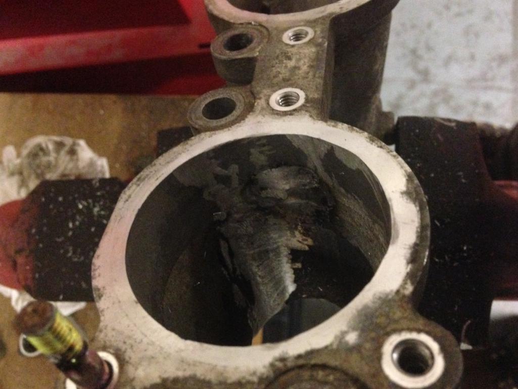
Cut down as much of the proud welds as possible with a carbide burr (saves flap wheels).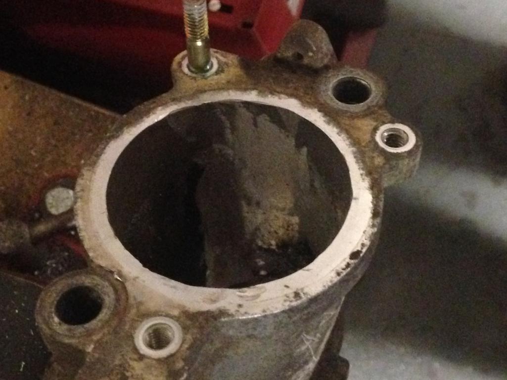
Posted by: jd74914 Jan 4 2017, 04:56 PM
The final product after hitting it with a 60-grit flap wheel. It's a bit tough to judge the surface from the poorly lit pictures, but it's pretty smooth. I'm reasonably happy with how they turned out for a few hours of work.
Thinking of blasting these and sending out for powder coating with a batch of stuff later on.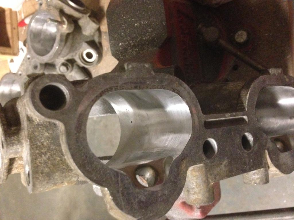
Posted by: jd74914 Jan 4 2017, 04:58 PM
Also unpacked the left rear inner fender wheel Chris (Tygaboy) cut out for me. This should be perfect for filling the huge hole in my left side!
I should have taken a picture of the packing...this sounds dumb but it was the best packed piece of sheet metal I've ever gotten. I wouldn't hesitate to buy from Chris again!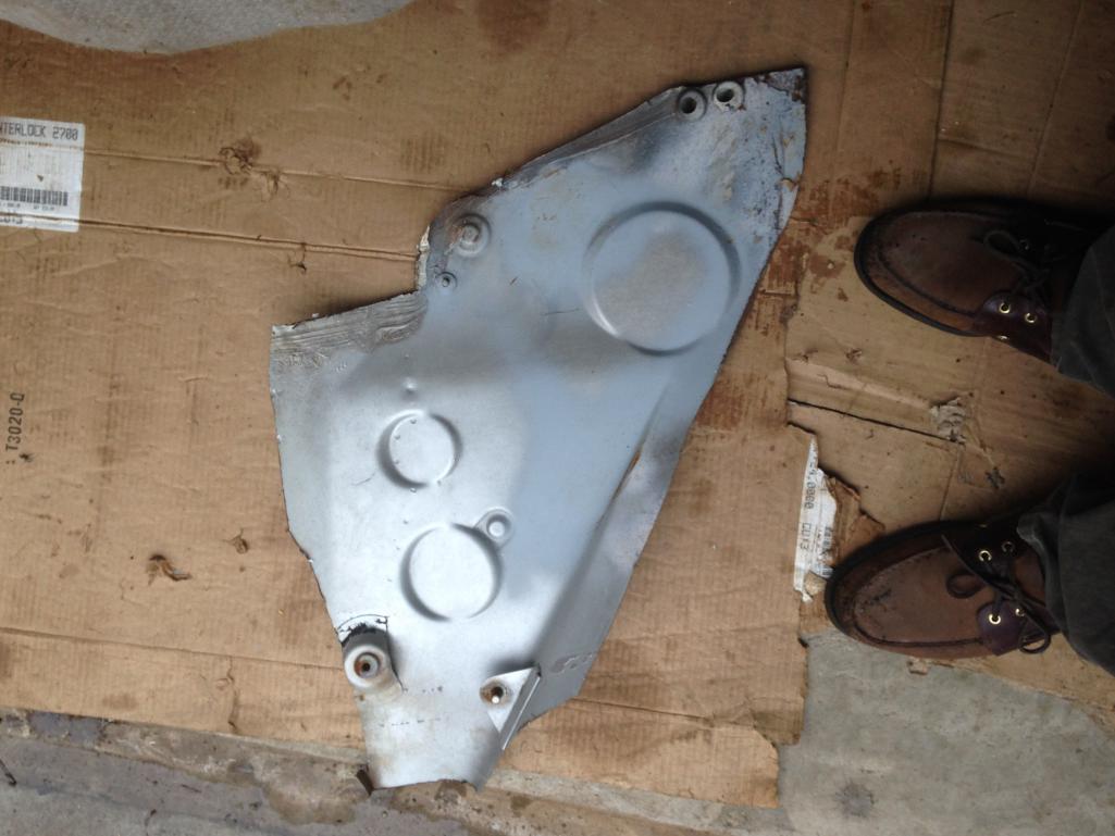
Posted by: jd74914 Jan 9 2017, 04:30 PM
Changing the sway bar mounts slightly to accommodate some well priced metal (free). Will put up a new model/final pics later this week.
At lunch I had a bit of time to turn the sway bar bearing mounts down. I'm pretty happy how they turned out-press fit is good to 0.0005" per telescoping gauge/mic (right in the middle of manufacturer requirements) and machined surface finish is pretty good. Didn't have any radius cutters, so a trashed old one got ground down. It actually worked pretty well besides a little chatter-a little thicker neck would have been nice.
Getting better with this whole turning thing. Ran out of time to drill the mounting holes and cut the backer plate. Another day...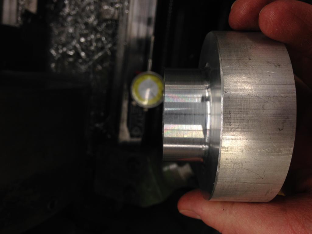
Posted by: tygaboy Jan 9 2017, 06:22 PM
Also unpacked the left rear inner fender wheel Chris (Tygaboy) cut out for me. This should be perfect for filling the huge hole in my left side!
I should have taken a picture of the packing...this sounds dumb but it was the best packed piece of sheet metal I've ever gotten. I wouldn't hesitate to buy from Chris again!
It's true, I really do rule...
Really happy to hear the piece will work for you. Now let's see some pics of you installing it. I have to repair the right side of my compartment and would love to watch you go first! Keep up the great work!
Chris
Posted by: jd74914 Jan 9 2017, 06:31 PM
It's true, I really do rule...
Really happy to hear the piece will work for you. Now let's see some pics of you installing it. I have to repair the right side of my compartment and would love to watch you go first! Keep up the great work!
Chris

Gotta wait for it to get a little warmer! Car thermometer said -4F on Sunday morning.
So for now it's doing inside stuff. Thanks!
Posted by: jd74914 Jan 11 2017, 03:01 PM
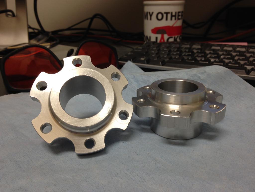
Finished up the sway bar bearing mounts over lunch today. Decided to go to a smaller outer diameter 6-bolt flange using M6 bolts vs. the OEM triple M8 bolt setup. The reliefs cut into the sides are really just there to look cool-they save ~20g (each part weights ~130g) which doesn't really do anything for a 900kg car.
Now just need to make some quick nuts plates and redrill/bore the through hold bigger on the inner fender stiffener and all of the vehicle attachment stuff will be done. 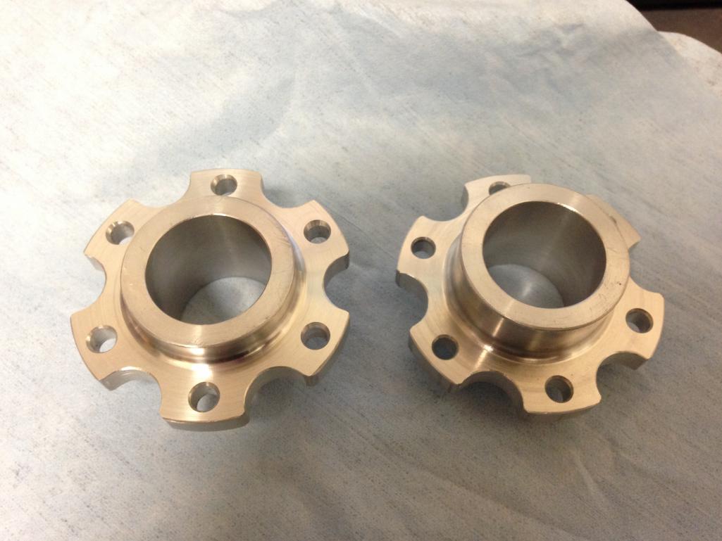
Posted by: tygaboy Jan 11 2017, 03:31 PM
LOVE those sway bar bearing mounts! Just beautiful. Nice work. 
Posted by: jd74914 Jan 11 2017, 05:09 PM
LOVE those sway bar bearing mounts! Just beautiful. Nice work.
Thanks!!
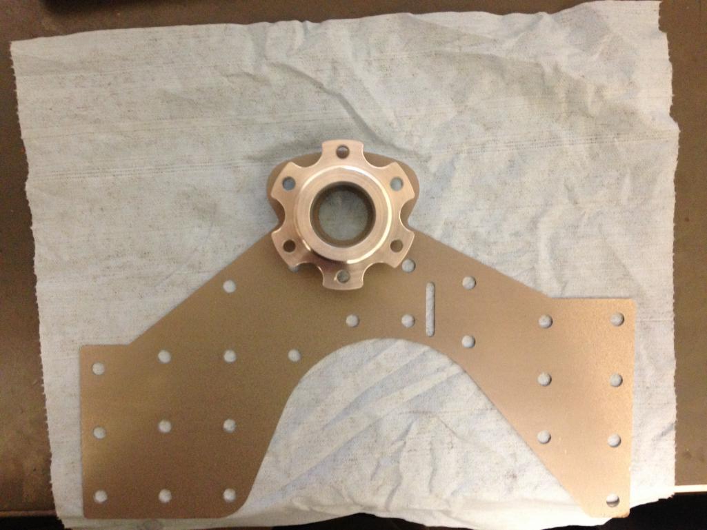
Forgot to add this picture before...its tough to see with the iPhone image warping, but with the reliefs it fits just perfectly into the recess and avoids the stiffener edge welds (save ~3/4" portion on top). Totally accidental but the smaller attachment bolts let it retain the stock hole spacing too which is awesome.
Attached thumbnail(s)
Posted by: Curbandgutter Jan 17 2017, 11:00 PM
Jim, your tractive force spreadsheet proves that if you shift at max torque you will drop the tractive force substantially. It proves that shifting is better near max horsepower. I just did a spreadsheet for my car. Very interesting information. Thanks for illuminating me.
Posted by: jd74914 Jan 30 2017, 05:20 PM
Haven't gotten too much done in the last few weeks on the car at least-real work-wise 2017 conference #1 paper/presentation #1 finished and #2 in progress. 
Yesterday I eked out some time and pulled the tail cone off the transmission and removed the center differential. It looks good and the transmission seemed to turn nicely so hopefully someone on Craigslist or NASIOC can use it. The locker will be build out of a broken center differential I picked up locally a few weeks ago. No pictures as of yet.
Today over lunch I turned some ABS "bushings" down for trial fitting the front sway bar. I was to test the install before having the mounts anodised, so I figured it'd be better to make a faux bushing to avoid ruining a good one on the uninstall.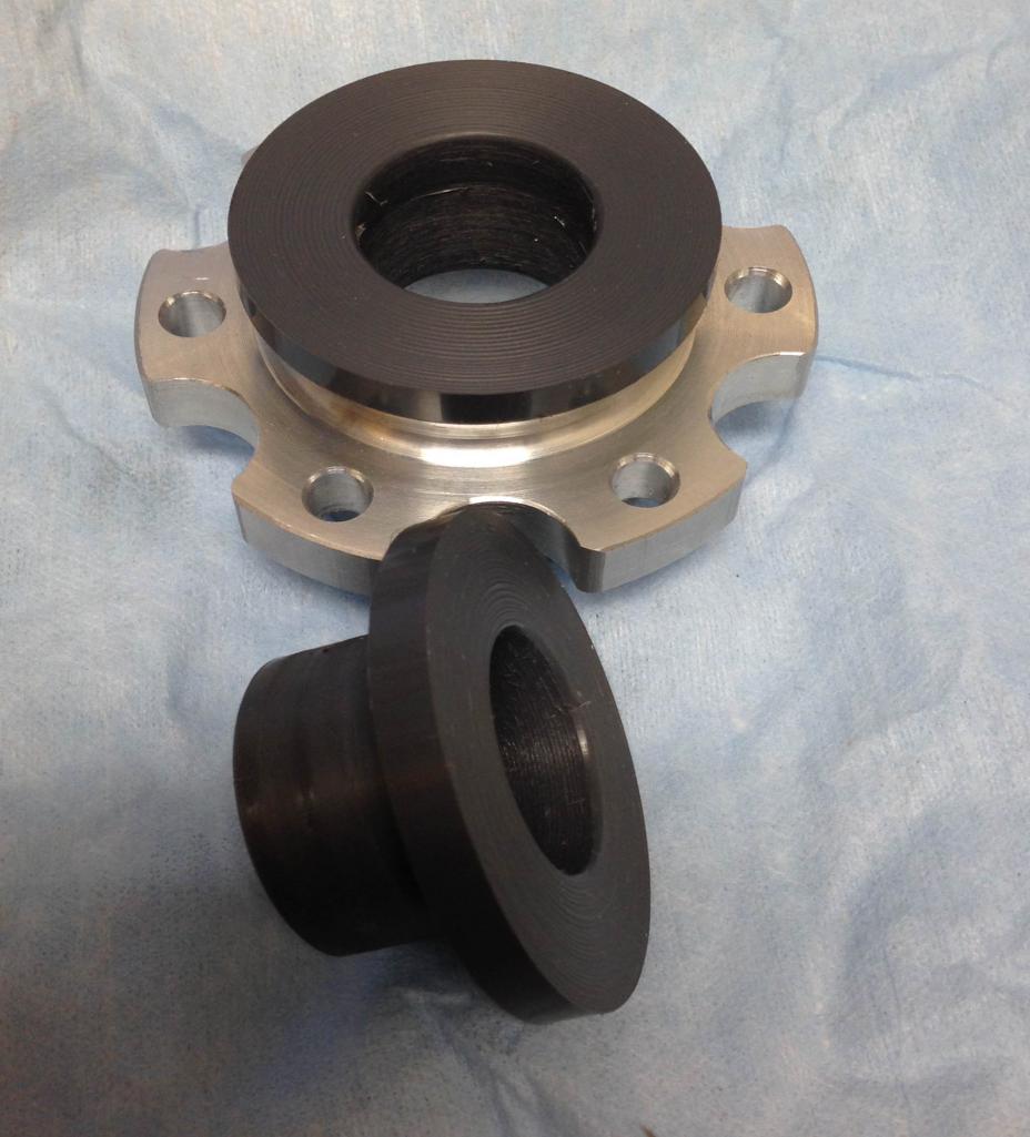
The aluminum plate came in to make the "fixture" for machining the front sway bar arms. Almost done with the arm and fixture design-hopefully some CAD drawings later this week. Need to cut down this beast! ~18 inches is just a little too long! 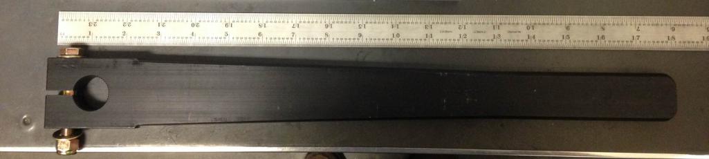
Semi-unrelated, but I've been gathering measurement equipment for blueprinting the engine when it gets rebuilt and I just got an awesome eBay deal on a sweet vernier mic...and just had to show off! This morning I adjusted it to within 0.0001" on a gage block. 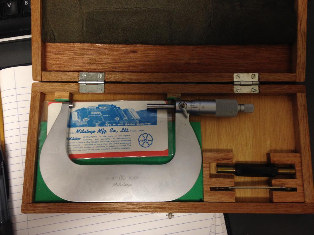
Posted by: jd74914 Jan 31 2017, 05:25 PM
Framed out the necessary larger holes in the sway bar stiffeners this afternoon. They look just a little ridiculous. Now they're ready for welding onto the car.
It was interesting, I noticed while indicating the original bar hole on the mill that the holes don't seem to be quite round. There must be some bearing slop or something in one of the axes of the laser that cut these since they're oval by a bit over 5 mils IIRC. Doesn't make any difference at all in performance and the pieces are really nice, just thought it was funny.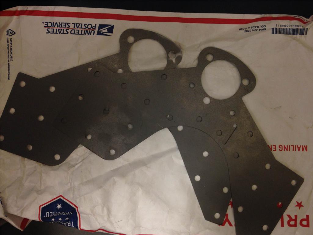
Posted by: jd74914 Jan 31 2017, 06:44 PM
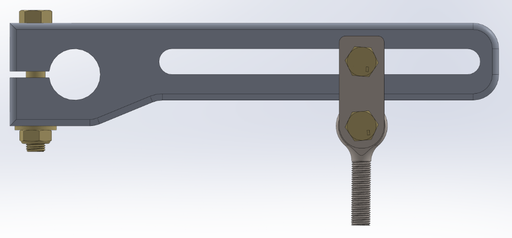
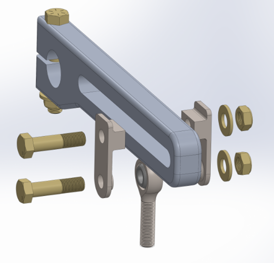
Threw together the first iteration of the front sway bar arms yesterday night and tonight. The original arms are machined aluminum blanks pre-made by Schroder (1"x48 spline to match the sway bar ends). They needed to be cut down significantly to even fit within the fenders. Most companies seem to just drill holes in the arms and have a single-shear fastener attaching the heim joint on the drop-link. That's really not great engineering and frankly scares me a bit, even though with a properly sized fastener it's perfectly safe. In retrospect, I wish I had bought the steel arms like Stephen (914forme) did since it's pretty easy to cut off the ends and weld on some steel double shear plates. I could do the same with these aluminum arms, but that's also a little worrisome since they would need post-weld heat treat.
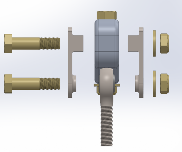
Given those facts, the easiest way I can come up with to put the whole assembly in double shear is to machine some blocks which fit into a groove in the arm. This will make the actual load bearing part of the block on the arm a long surface (bolts not only for clamping force). On the drop link side, the block will be machined into a spacer to allow some extra heim misalignment.
The fasteners are NAS AN6-14A meaning that they are 3/8"-24 with a 1-19/32" overall length and 15/16" grip length. They are a bit more expensive than generic bolts at McMaster Carr (best NAS prices are at Aircraft Spruce) but the extended grip length means that the threads are never held in shear which is nice for peace of mind.
Thinking about it now the 3/8" hardware might be a little overkill-5/16" might be better. Gotta do some math. Overall weight of the assembly as shown is ~1.4# per side.
Anyone have any thoughts?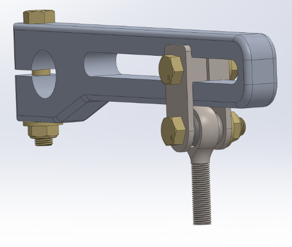
Posted by: Andyrew Feb 1 2017, 01:19 AM
Very cool design on the sway bar arms.
Let me know if you want to make a second set, I have the same basic sway bar in my car and have had it in there for 11 years with no arms . Just havent had the time to fab up some arms. (Mine are 1 1/4 x 48 spline)
PS I took the simple crude route for the bar mount.
http://www.914world.com/bbs2/index.php?showtopic=50483&hl=nascar
Posted by: Curbandgutter Feb 1 2017, 08:42 AM
Wow we have talent on this forum yalll!!
Posted by: jd74914 Feb 1 2017, 03:55 PM
Very cool design on the sway bar arms.
Let me know if you want to make a second set, I have the same basic sway bar in my car and have had it in there for 11 years with no arms
. Just havent had the time to fab up some arms. (Mine are 1 1/4 x 48 spline)Thanks!
I know the feeling-these arms have been in my possession for maybe 5 years just sitting in a box. If I like the way they turn out I might be up for making a few more; just have to make sure I'm happy with these first.
Wow we have talent on this forum yalll!!
Hahahahahaha Thanks Rudy! I'm drooling over yours and the other builds more than mine! Especially you and Chris who move at a super fast pace.
Posted by: Racer Chris Feb 1 2017, 04:10 PM
Anyone have any thoughts?
I think I like your machined blocks better than the welded "H" shaped bracket that I use in my kits.
Like you, I prefer not to use the single shear attachment method.
Posted by: jd74914 Mar 1 2017, 12:54 PM
Working really slowly this month...too much other life going on!
In real life I just booked plane tickets (and got a really awesome deal) to fly into Rome and out of Palermo, Sicily 12 days later in June. Pretty stoked
Otherwise I really didn't get anything done. Sold the center differential from the WRX transmission on NASIOC and have almost broken even on it. Hopefully someone will bite on the transfer gears/extension housing soon.
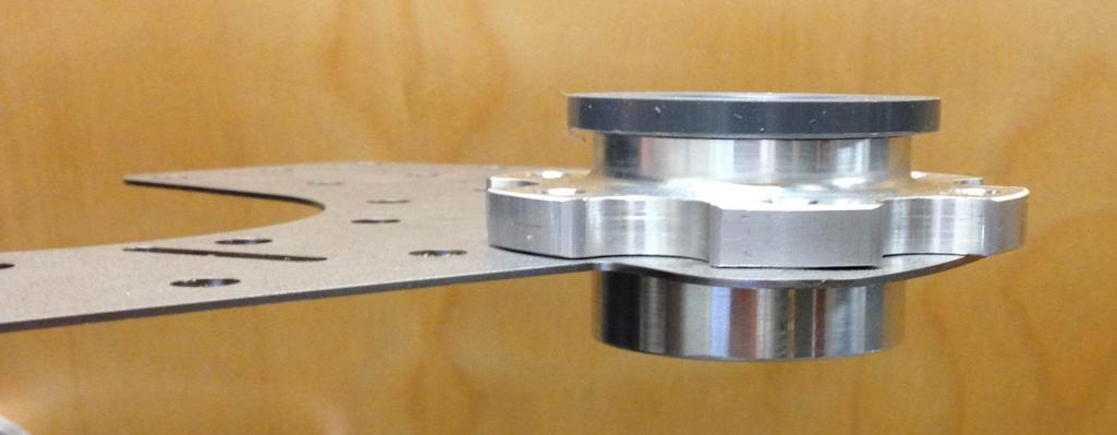
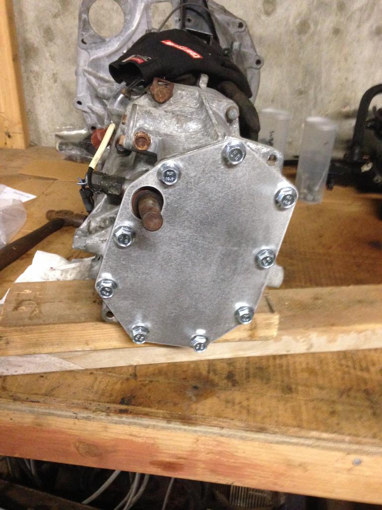
Pictures of Ross's blockoff plate and the removed pieces. I found a bad center diff locally and bought it to cut apart. Its now taken apart and the plan is to get it cut this week and then pull the nut off the gear stack and do some measuring. Before welding I'm going to turn some alignment pins to keep everything concentric. 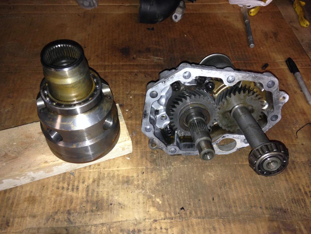
Posted by: jd74914 Mar 1 2017, 12:54 PM
Pulled apart bad center diff ready for cutting.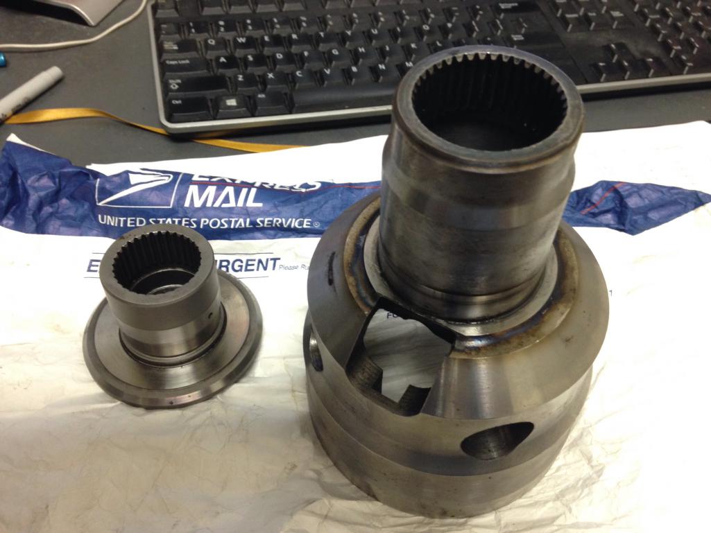
Posted by: jd74914 Mar 10 2017, 09:53 AM
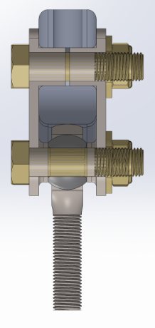
Cut up the differential last night and test fit in the transmission. I'm making the 2WD lockout in the same way that 914pipe and jpnovak did by welding the input/output splines on the center differential together.
jpnovak: http://www.914world.com/bbs2/index.php?showtopic=104513
914pipe: http://www.914world.com/bbs2/index.php?showtopic=298248&st=0&p=2419604&#entry2419604
My splined pieces look are identical to those of 914pipe; jpnovak had a second, smaller splined section in the middle of his spider section.
The guy who owned this thing before me removed the big carrier bearing before selling it to me. I didn't notice at that time (or even really until I tried to slide the thing into my transmission), but he used a BFH to remove the bearing rather than a press and damaged the front edges of a bunch of splines on one side. It took about 30 minutes with some thread files to fix the leading edges and get it slid into the diff.
First step is to cut the splines off of the outer casing and spider gear. I cut a bit long on the spider since I wanted to protect the nut/transmission from spatter while tack welding.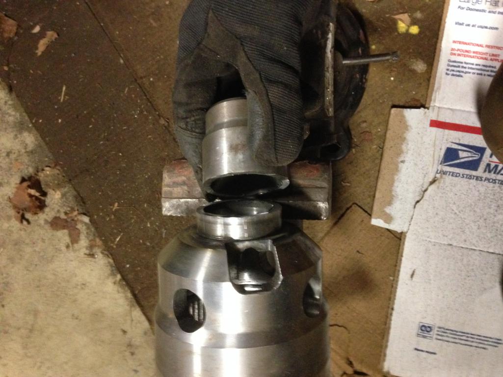
Posted by: jd74914 Mar 10 2017, 09:57 AM
Crudely filed housing splines. You can see where it was hit with a hammer. 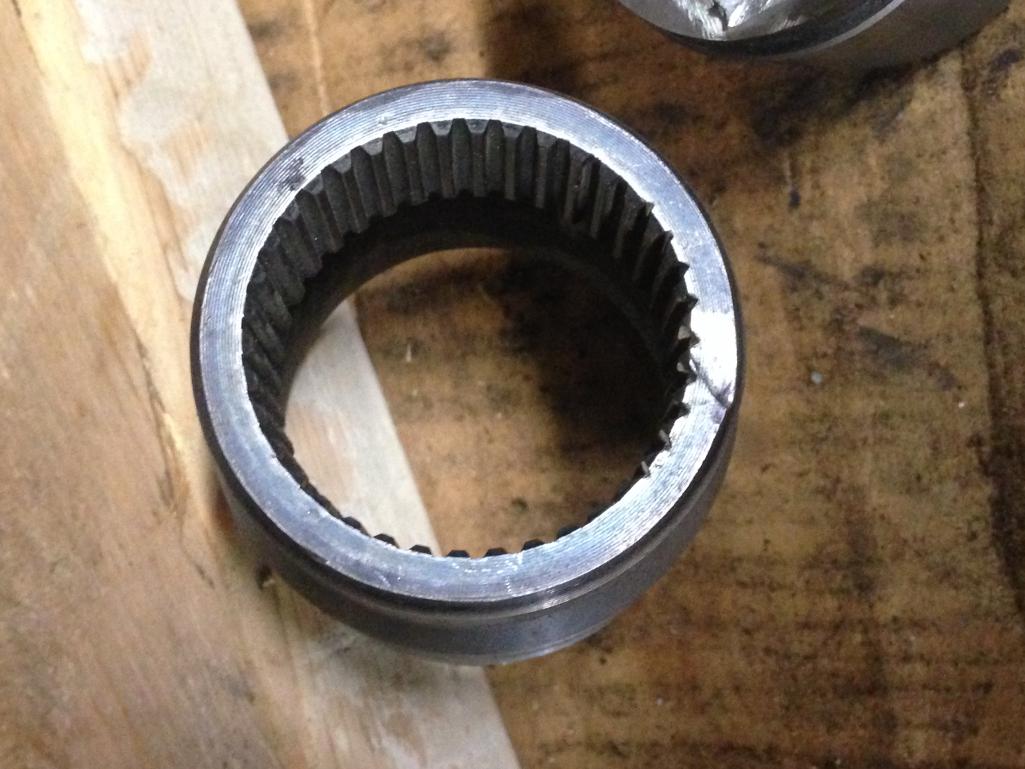
Next the two pieces were deburred and fit into the transmission. After making sure they were seated I threw on a few tacks with the MIG to hold everything in place. The structural welds will be TIG.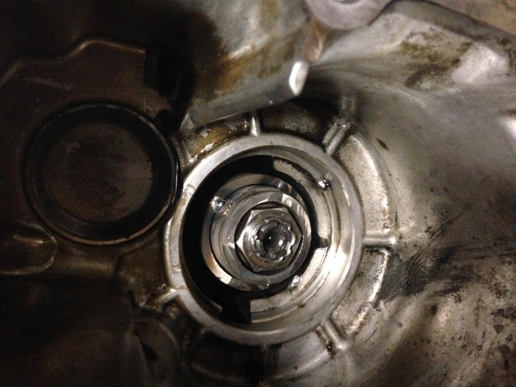
Posted by: jd74914 Mar 10 2017, 10:04 AM
Of course it wouldn't slide out of the differential nicely by hand or even with some picks. Conveniently, Subaru left some access slots for a narrow puller. It turned out to be just enough room for a cheap generic valve spring compressor to fit. I just had to sand about 0.050" off one of the puller edges and remove the spring centering piece and it fit in like a charm.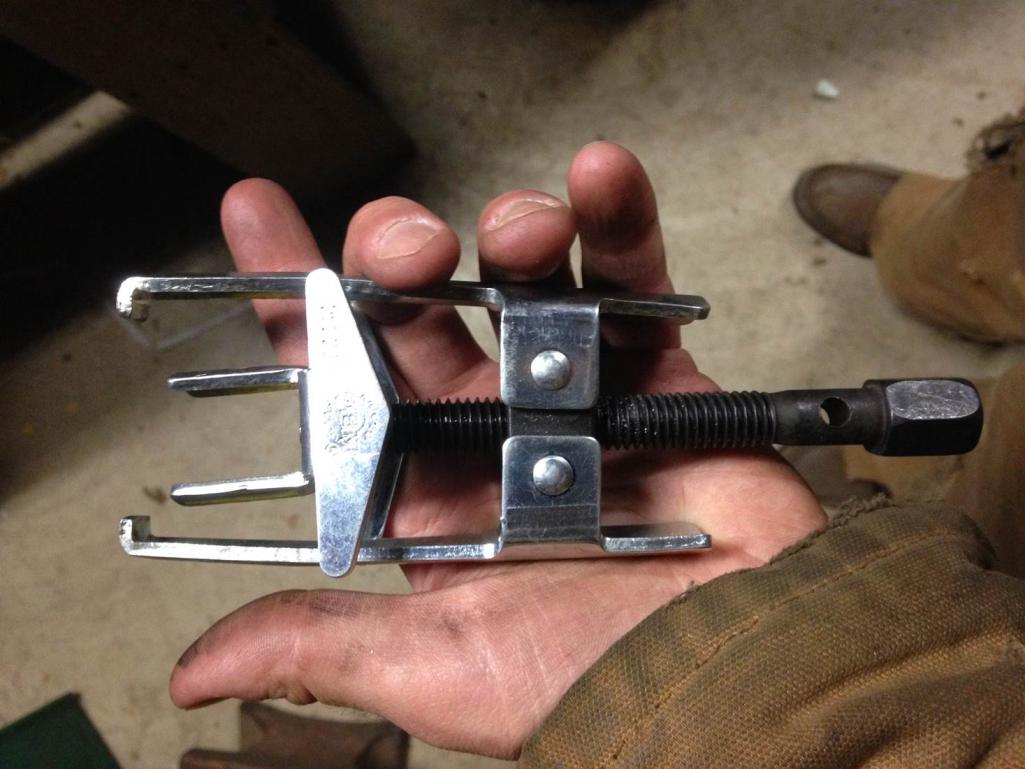
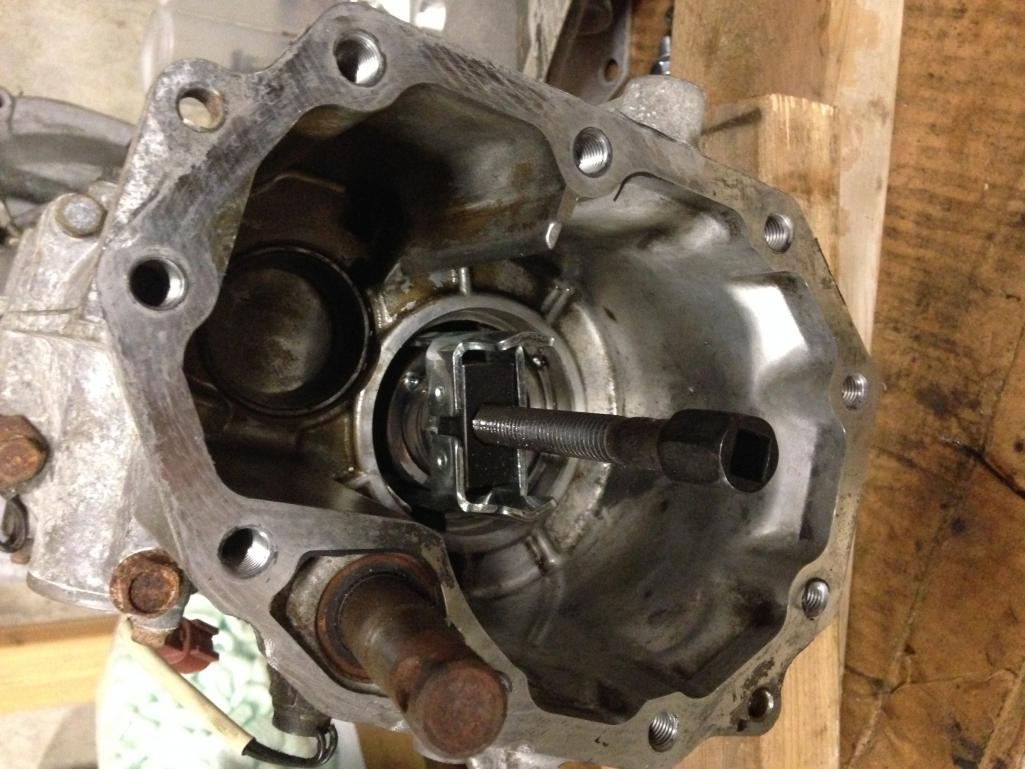
Locker pulled out. I'm going to put a few more solid tacks on the outside after turning a quick insert to keep everything concentric. After the outside is a bit stronger the plan is to TIG up the inside, turn it to the correct length to fit the nut and washer on (about the currently length of the outer piece), and full weld the outside with the insert in place to keep everything straight. Then hopefully it all fits together! That would complete the internal transmission stuff for now. 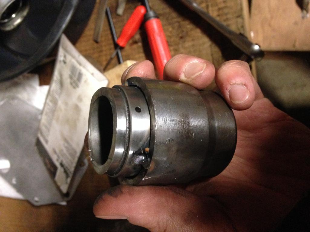
Posted by: jd74914 Nov 11 2017, 02:45 PM
No real car progress to report. My crazy school schedule hasn't really been conducive to getting anything done outside of the lab. I've basically only finished the welding on the adapter in the last post.
Once my degree is finished I'll have much more restricted access to machinery, so I've been watching CL and other places for equipment for the garage. Some of you may have seen my mini horizontal mill thread in the Sandbox.
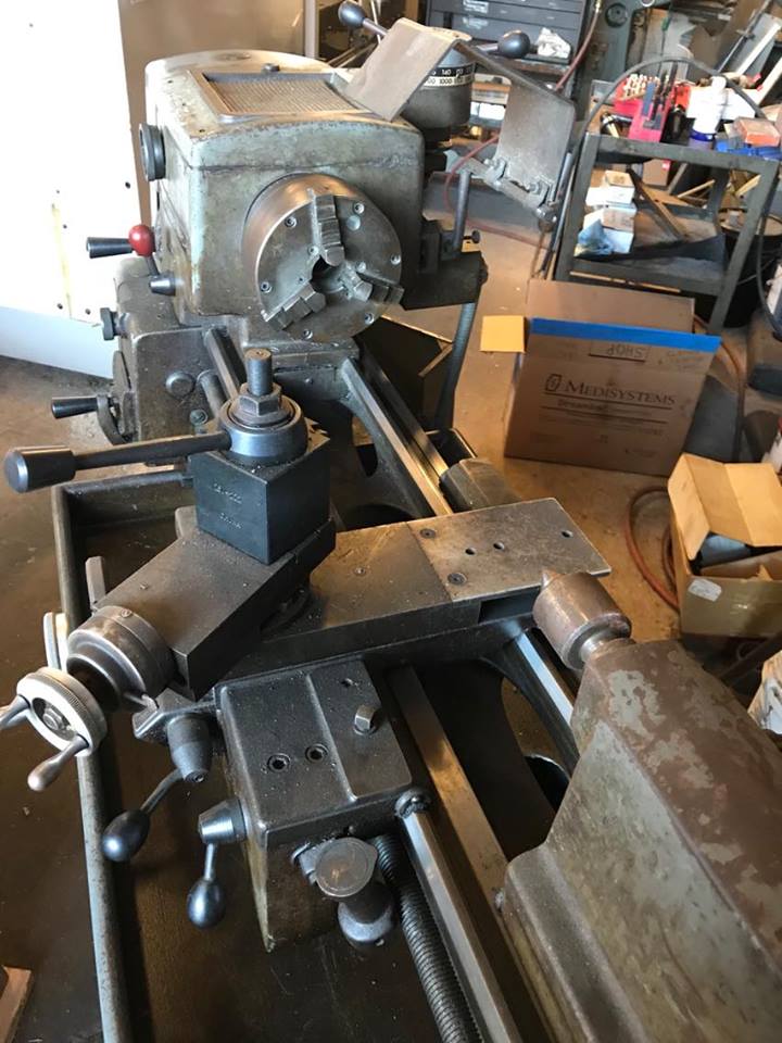
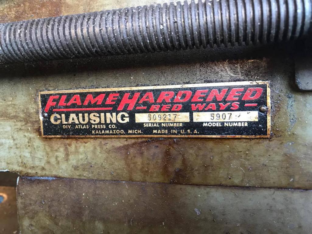
My newest score is the Clausing 5907 lathe. It's a 12" swing with hydraulic Reeve drive for continuously variable speed control from 52-2000 rpm (including back gear). It weighs ~1200# so it was a little tough getting off the truck. Everything seems to work quite well and there is very little wear in the ways thanks to the hardening. The cross-slide doesn't have too much back lash and the Reeves drive works well. We'll see if the drive keeps working nicely, if not it'll get removed and replaced with fixed drive. The only real issue at this point is excessive lash in the carriage feed which I believe is caused by a worn bushing singe the rack gear and pinion look good. Looks pretty easy to fix after removing the apron and some people have added a second bearing in the rear part of the casting to kill this problem dead.
The owner needed space ASAP in his shop so I got lucky and basically stole it-asking price was less than the value of the new boring bar and insert tool holder. It came with a bunch of new [knockoff] Aloris tool holders, insert tools with spare inserts, and the original lamp post and tool holders. Next parts to find are a nice drill chuck and the MT4-1/2 to 5C adapter to run some collets for smaller jobs. And maybe an independent adjust 4 jaw chuck too. Tough part is finding economical L-00 parts so if anyone has anything... 
It's a 3-phase motor so the next step after doing some cleaning is either finding a 1PH-input/3-PH output VFD or building a converter. Small project and well worth it for the price. 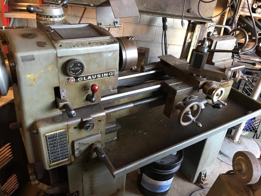
Posted by: Racer Chris Nov 12 2017, 06:41 AM
Jim, I have a really big rotary phase converter at the shop which I would like to sell.
Posted by: 914forme Sep 14 2018, 05:32 PM
Updates? 
Powered by Invision Power Board (http://www.invisionboard.com)
© Invision Power Services (http://www.invisionpower.com)