Printable Version of Topic
Click here to view this topic in its original format
914World.com _ 914World Garage _ Terminals
Posted by: martinef1963 Jan 5 2005, 01:26 PM
Yes I am a rookie (newbie) and am constantly perplexed by the "jargon, terminology" of the 914 world. 
Can someone esplain to this rookie what is meant when manuals say: You can test it by measuring the resistance between terminal # whatever and # whatever......... 
thanks - another question from the ranks of a newbie...... 
Posted by: SLITS Jan 5 2005, 01:31 PM
terminal = connection or did you mean the movie  ?
?
Which item are you trying to test?
Posted by: lapuwali Jan 5 2005, 01:41 PM
You take an ohmmeter, which today will usually be found in the form of a multimeter (available at most places that sell tools for $20 or so). The meter will measure resistance (in ohms), voltage, and current, plus probably a few other things.
If the manual spells out you need to measure resistance, you use the ohms setting on the meter, and touch the probes to the two places mentioned. If one of those places mentioned is "ground", you attach it to someplace on the body, or the - terminal of the battery, if it's nearby. The meter will display the resistance, in ohms, which needs to be compared against whatever the manual says it should be. If you don't get the required number, try fooling with the probes and exactly where they contact a bit. You may need to clean the places the probes touch (which, in fact, may be the cause of the very problem you're trying to diagnose). Electrons don't like to cross old, corrodded connections. If one of the connections is ground, a painted part of the body may not work. You'll probably find an unpainted part, like the case of the gearbox or engine, or a bolt that connects directly to the body, will work. Any brown wire on the car will, eventually, connect to ground. A cluster of brown wires attached to a bolt on the body is a ground point.
If the manual says to measure voltage, there'll be a DC voltage setting on the meter you need to use instead. You won't use the AC voltage setting on the meter. You're also less likely to use the current (amps) setting in most procedures.
None of this is 914 specific, or even car specific, but is basic electricity. There are a few sites out there that explain basic electricity and electronics. It's not the easiest subject to understand for many people, so don't be discouraged if it all seems unfathomable to you at first.
Posted by: Mueller Jan 5 2005, 01:43 PM
there are male and female terminals....hope you can figure out the differance 
Attached image(s)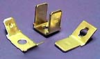
Posted by: martinef1963 Jan 5 2005, 02:22 PM
Thanks for the direction, however, still am wondering were these terminals are - for example:
"The coils can be tested by measuring the resistance between terminals #7 & #15 (should be about 90 ohms) and between #8 & #10 (should be about 350 ohms)."
This particular item is the pressure sensor: the real question is were are these "terminals" located?
thanks - the rookie.
Posted by: restore2seater Jan 5 2005, 02:27 PM
What manual are you useing? There should be a wireing diagram somewhere in the book that labels everything.
Posted by: Mueller Jan 5 2005, 02:38 PM
almost every item that the wiring harness plugs into has a terminal number assigned to it....the MPS has 4 terminals....the d-jet trigger points on the distributor have 3, numbers 12, 21 and 22...if you look at the Haynes wiring diagram it should help some to understand
Posted by: Demick Jan 5 2005, 02:43 PM
| QUOTE (martinef1963 @ Jan 5 2005, 12:22 PM) |
| Thanks for the direction, however, still am wondering were these terminals are - for example: |
A terminal is simply an electrical connection. Usually easy to find because connectors are plugged into or onto them.
Posted by: SLITS Jan 5 2005, 02:45 PM
| QUOTE (martinef1963 @ Jan 5 2005, 01:22 PM) |
| Thanks for the direction, however, still am wondering were these terminals are - for example: "The coils can be tested by measuring the resistance between terminals #7 & #15 (should be about 90 ohms) and between #8 & #10 (should be about 350 ohms)." This particular item is the pressure sensor: the real question is were are these "terminals" located? thanks - the rookie. |
Where the wiring harness plug plugs into the Manifold Pressure Sensor and they are labeled on the plastic housing on the MPS. They are the little metal thingys sticking out at you from the black plastic housing.
Posted by: Mueller Jan 5 2005, 02:50 PM
the yellow arrows point to the terminals on the component....some of these will go to the ECU, some might go to another component or the fuse block via the wiring harness.............
Attached image(s)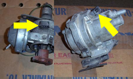
Posted by: Dave_Darling Jan 5 2005, 05:44 PM
Most of the electrical parts have raised numbers molded into the plastic right by where the plug goes. Look at the numbers, and compare them to the numbers that the manual is calling for. Chances are pretty good (sadly not 100%!) that you'll find the same numbers on the part that are in the instructions. I know that you do on the MPS, for instance. It can take a little work to see the numbers, though. Look on the one side and then the other of the plastic surrounding where the plug goes. Hunt around for the numbers; they should be near wherever the plug goes.
--DD
Posted by: Porsche Rescue Jan 5 2005, 05:49 PM
Many of the fuel injection checks are done by unplugging the harness from the control unit and using the terminals in the large plug (not the control unit). A wiring diagram will show the terminal numbers (Haynes may have it). I think the pressure sensor test you are referring to is done that way.
Powered by Invision Power Board (http://www.invisionboard.com)
© Invision Power Services (http://www.invisionpower.com)