Printable Version of Topic
Click here to view this topic in its original format
914World.com _ 914World Garage _ LEDs For Front Turnsignal Bucket
Posted by: Spoke Mar 30 2014, 09:35 PM
On the radar are LED boards for the front turnsignal bucket. LEDs would be pointing directly to the front of the car to focus optical energy forward.
There are 3 versions I can think of:
1) US lens: All amber LEDs; all on low for running lights; on high for turnsignals.
2) Euro lens: White LEDs on the lower section; on for running lights; amber for turnsignals. White LEDs would turn off when turnsignals are on.
3) Clear lens: White running LEDs on the outside of the lens; Amber LEDs in the center for turnsignals. White LEDs would turn off when turnsignals are on.
Which versions would folks want? I think I would like the clear lens. The oval running lights would be unique.
Mock up of turnsignal LED PCB.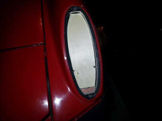
PCB for clear lens.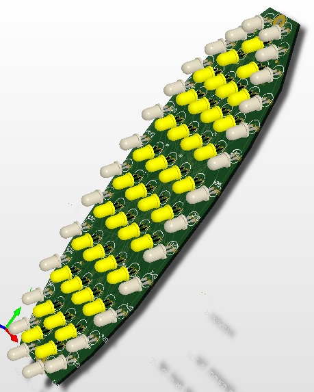
PCB for Euro lens.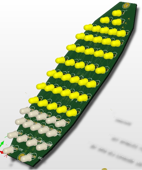
Posted by: R8CERX Mar 30 2014, 11:47 PM

On the radar are LED boards for the front turnsignal bucket. LEDs would be pointing directly to the front of the car to focus optical energy forward.
There are 3 versions I can think of:
1) US lens: All amber LEDs; all on low for running lights; on high for turnsignals.
2) Euro lens: White LEDs on the lower section; on for running lights; amber for turnsignals. White LEDs would turn off when turnsignals are on.
3) Clear lens: White running LEDs on the outside of the lens; Amber LEDs in the center for turnsignals. White LEDs would turn off when turnsignals are on.
Which versions would folks want? I think I would like the clear lens. The oval running lights would be unique.
Mock up of turnsignal LED PCB.
PCB for clear lens.
PCB for Euro lens.
NICE!
very handy with them circuits!!

Posted by: Cairo94507 Mar 31 2014, 05:56 AM
Outstanding!!!!
Posted by: Chris H. Mar 31 2014, 06:19 AM
Update...I want the US version (#1).
Posted by: Harpo Mar 31 2014, 06:22 AM
Awesome can't wait
David
Posted by: CptTripps Mar 31 2014, 07:33 AM
So is this right for #3?
Attached image(s)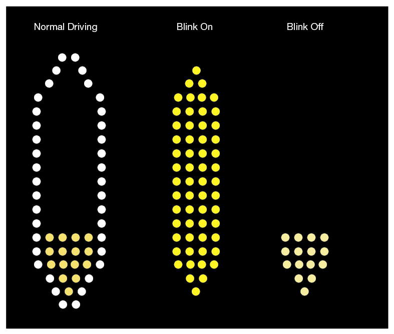
Posted by: Chris H. Mar 31 2014, 07:45 AM
That looks cool! Reverse euro lens. You could also make the entire center section slightly lit in amber for driving. I'm sure you could have it either way.
Posted by: JmuRiz Mar 31 2014, 07:59 AM
Very cool, "PCB for clear lens" would look great on my italian lens car.
Posted by: Zimms Mar 31 2014, 08:22 AM
I am in for Euro lights
Posted by: Spoke Mar 31 2014, 11:51 AM
So is this right for #3?
I was thinking just the outer ring of white LEDs for driving, then center pic for turnsignals blink-ON, then no LEDs at all for turnsignals blink-OFF. But I'm not married to this.
I want to find out what suites folks best. There's too many good ideas amongst the 914world for me to say how it will be.

Posted by: CptTripps Mar 31 2014, 11:55 AM
I was thinking just the outer ring of white LEDs for driving, then center pic for turnsignals blink-ON, then no LEDs at all for turnsignals blink-OFF. But I'm not married to this.
You'll want SOMETHING illuminated on the light when it's blinking. If not, then you run the risk of someone not seeing that corner of your car. My mind went to someone cutting a left-hand turn too close and clipping me. I could be wrong though...who knows. I just thought that it'd be nice to have something lit there when it's in "blink mode".
Rock on man. Can't wait to see this all done! Put me on the "tester" list.

Posted by: JmuRiz Mar 31 2014, 12:40 PM
The white daylight running light ring going off when the yellow turn signals are flashing is similar to what the Audis do with their OE DRLs.
Posted by: Spoke Mar 31 2014, 03:03 PM
The white daylight running light ring going off when the yellow turn signals are flashing is similar to what the Audis do with their OE DRLs.
This is why I thought about shutting off the running light when the turnsignal is on. I've seen this on several new cars with LED running lights. It allows that side to emphasize the turnsignal light w/o drowning it out with the running light.
Posted by: Cairo94507 Mar 31 2014, 03:36 PM
My 997.2 has the front LED running lights and when you turn on the turn signal the running light remains illuminated and an orange LED bar illuminates and flashes. I think it looks good. I always thought the Audi looked funny stopped at a light with a turn signal on and that running light off and the other on. Just my 2 cents.
Posted by: mrholland2 Mar 31 2014, 03:57 PM
The white daylight running light ring going off when the yellow turn signals are flashing is similar to what the Audis do with their OE DRLs.
This is why I thought about shutting off the running light when the turnsignal is on. I've seen this on several new cars with LED running lights. It allows that side to emphasize the turnsignal light w/o drowning it out with the running light.
I really like the version in the drawing. Can the DRL halos be REALLY obnoxiously bright? I want the people that wanna hit me to be in PAIN when they see me!!!!
Posted by: mrholland2 Mar 31 2014, 04:25 PM
The white daylight running light ring going off when the yellow turn signals are flashing is similar to what the Audis do with their OE DRLs.
This is why I thought about shutting off the running light when the turnsignal is on. I've seen this on several new cars with LED running lights. It allows that side to emphasize the turnsignal light w/o drowning it out with the running light.
I really like the version in the drawing. Can the DRL halos be REALLY obnoxiously bright? I want the people that wanna hit me to be in PAIN when they see me!!!!
You could use it with American lenses too, yes?
Posted by: mrholland2 Apr 2 2014, 11:40 PM
Soooooo do we have a final answer on this? I love this idea!! 
Posted by: Spoke Apr 2 2014, 11:59 PM
Soooooo do we have a final answer on this? I love this idea!!
I'm targeting 3 versions:
US (all amber lens): All amber LEDs. All on softly for running lights; bright for turnsignals
Euro (clear bottom; amber top lens): White LEDs on the bottom, on bright when running lights on; top amber LEDs blink bright for turnsignals (the amber could be on softly or off for running lights for running lights)
Clear lens: White LEDs around perimeter, on bright when running lights on; center amber LEDs blink bright for turnsignals (the amber could be on softly or off for running lights)
After conversation with CptTripps, I don't think I will blank out the white LEDs when the turnsignal is blinking. More light = better.
Posted by: 69telecaster Apr 3 2014, 06:56 AM
Aren't original bulbs white on US models?
Wouldn't white LED's behind the amber lenses be better?

cm
Posted by: CptTripps Apr 3 2014, 07:22 AM
Wouldn't white LED's behind the amber lenses be better?
Amber light through amber lenses will give more/better light. The wavelengths match, so you'll get more color.
::: someone correct me if I'm wrong, I just remember reading an article about that :::
Posted by: chads74 Apr 3 2014, 07:47 AM
I would love a set. I am keeping my fingers crossed I made the list for the rear set.
Posted by: Spoke Apr 3 2014, 09:37 AM
Wouldn't white LED's behind the amber lenses be better?
Amber light through amber lenses will give more/better light. The wavelengths match, so you'll get more color.
::: someone correct me if I'm wrong, I just remember reading an article about that :::
This was posted in my LED brake thread. One picture says a lot.
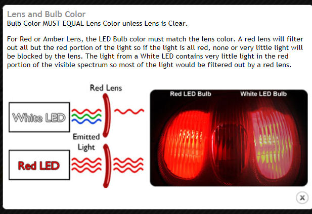
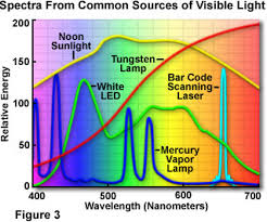
Here's the spectrum of a white LED compared with other light sources including a tungsten lamp. Notice how the LED, vapor lamp, and bar code scanner have high peaks at certain frequencies.
Much of the white LED's power is filtered out by the amber lens.
Posted by: mrholland2 Apr 3 2014, 01:59 PM
Sooooo. . what if I want to use the Euro version with an American lens? Will it be crappy or decent?
Sean
Soooooo do we have a final answer on this? I love this idea!!
I'm targeting 3 versions:
US (all amber lens): All amber LEDs. All on softly for running lights; bright for turnsignals
Euro (clear bottom; amber top lens): White LEDs on the bottom, on bright when running lights on; top amber LEDs blink bright for turnsignals (the amber could be on softly or off for running lights for running lights)
Clear lens: White LEDs around perimeter, on bright when running lights on; center amber LEDs blink bright for turnsignals (the amber could be on softly or off for running lights)
After conversation with CptTripps, I don't think I will blank out the white LEDs when the turnsignal is blinking. More light = better.
Posted by: morgan_harwell Apr 3 2014, 03:39 PM
I like #2 for my 914:
2) Euro lens: White LEDs on the lower section; on for running lights; amber for turnsignals.
Posted by: Spoke Apr 3 2014, 04:11 PM
Sooooo. . what if I want to use the Euro version with an American lens? Will it be crappy or decent?
Sean
Should work ok. White LEDs may look a little less bright.
Will have to test this out. I am ordering some white LEDs to do some testing. I need to see how bright the white LEDs are plus I need to measure the on voltage to determine the bias circuit.
Posted by: ConeDodger Apr 3 2014, 04:14 PM
EURO
please... 
Posted by: john77 Apr 3 2014, 04:48 PM
I'm in for a set, just not sure which one. I have euro lenses but are the US/euro housings different? I opened mine up expecting to find a bulb top and bottom but there was only one up in the top. Yes, I'm new to 914s...
Posted by: StratPlayer Apr 3 2014, 06:12 PM
I'd be in for a set of the Euro's
Posted by: scottb Apr 3 2014, 06:25 PM
in for euro pair
Posted by: zambezi Apr 3 2014, 08:37 PM
I would be in for one set as well. I have the clear Italian lenses so option 3 would be for me.
Jim
Posted by: cconcepcion Apr 5 2014, 05:04 PM
euro por favor! 1 pair with blanking feature...
Posted by: Zimms Apr 5 2014, 10:23 PM
I am in for 1 pair of euros
Posted by: monkeyboy Apr 6 2014, 12:45 AM
1 set of Euros when they are ready. Thank you.
Posted by: Rleog Apr 8 2014, 10:21 AM
Add me to the Euro lens list.
Posted by: McMark Apr 8 2014, 11:35 AM
It would add to build cost, of course, but a selector switch to change configuration and a universal board?
But there probably isn't space for that either.
Posted by: zymurgist Apr 8 2014, 11:43 AM
I like the Euro idea. May want to run with amber lenses for now though, since that is what I have.
Posted by: IanS Apr 8 2014, 11:56 AM
I would like an amber set please Mr. Spoke
Posted by: Harpo Jun 14 2014, 10:12 AM
Good morning Jerry,
Any update on the Front turn signal buckets.
Thanks
David
Posted by: 75-914 Jun 14 2014, 11:14 AM
Euro for me too!
Posted by: tomeric914 Jun 14 2014, 08:31 PM
Jerry, you suck. Now I HAVE to buy these too. 
I like the Euro setup that you're working on especially if it plugs right into a standard US setup and only requires a lens change.
Put me down for a pair.
Posted by: sportlicherFahrer Jun 15 2014, 02:49 AM
+1 for front Euro as well please! REALLY like the way the full Euro/Brake set up looks on the rear.
Posted by: jacksun Jun 15 2014, 06:12 AM
just and idea to be used or not.
why not tie in the turn signals with the side marker light..
it blinks with the turn signal.
Posted by: orthobiz Jun 15 2014, 06:45 AM
US lens for me. Especially after my rear kit arrives and is installed!
Paul
Posted by: Spoke Jun 15 2014, 07:10 AM
Haven't made too much progress on the fronts. 
There are 2 issues to work out with the mounting of the LEDs on this board. Given that the LEDs will be mounted such that they are at 45 (or so) degree angle from the board, I've been in consultation with the guys at work on how to mount the LEDs about 3/16 to 1/4 of an inch above the board, then bend all the leads so the LEDs all point in the same direction (toward the front of the car).
The second issue is how to secure the LEDs to the board as to take the stress of vibration off of the solder on the long leads. We're thinking the LED body will need to be glued, caulked, or conformal coated to the board.
Posted by: 75-914 Jun 19 2014, 08:09 PM
sent PM
Posted by: Spoke Jun 26 2014, 09:16 PM
Had some down time on the rear LED boards while my buddy's 3d printer was repaired and the flow of plastic clips dried up so I worked the layout of the front LED boards.
Seems more interest in the Euro front bucket so I'm starting with that version.
It would be ideal to make a universal board do US and Euro format unfortunately the white running light LEDs have a higher voltage drop than the amber thus 3 white LEDs are in series versus 4 amber LEDs per string. Therefore it's difficult to make a Euro board into a US board.
Here's some 3d drawings of the board so far.
The board has 48 amber turnsignal LEDs and 21 white running light LEDs.
There will be a configuration option with the Euro lights: The amber turnsignal LEDs can be configured to be dimly on for running lights or off for running lights.
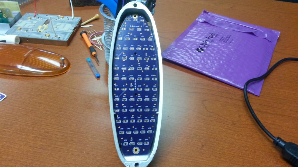
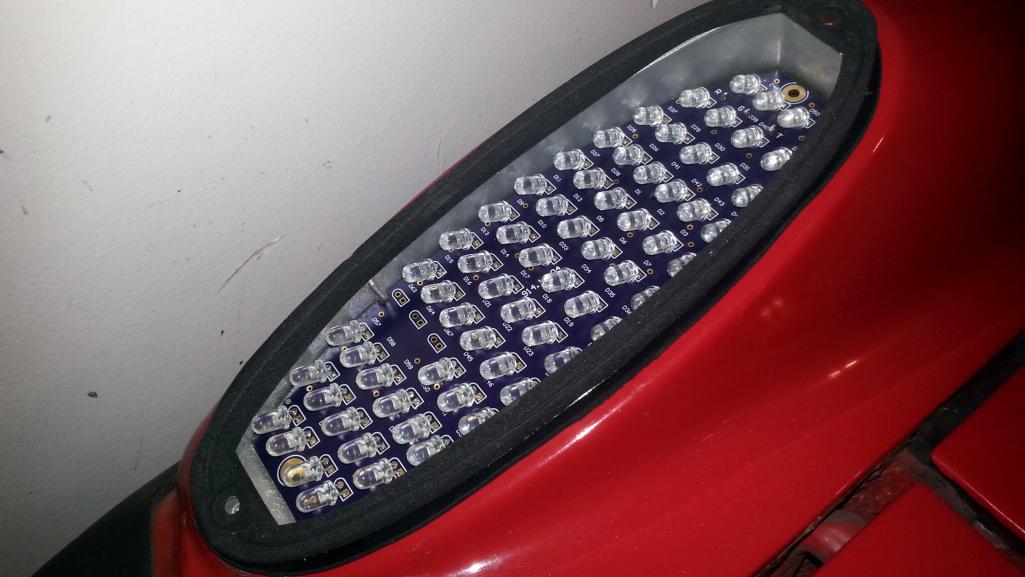
Here's what the board looks like now when viewed from the front of the 914.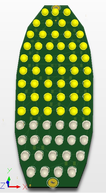
Here's a side view of the board. As SirAndy pointed out with the rear lights, the dispersion angle is tight with these LEDs so they must be pointing in the direction that light is intended; that is directly in front of the car. Mounting them perpendicular to the board will not do as the light will be pointed into the sky at about a 45 degree angle.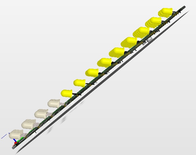
This pic shows a close-up of the one difficulty with the LED angle that I'm trying to solve. Unlike this pic of the board, the leads will be bent and perpendicular though the board. Somehow the LED has to be soldered about 3/16 of an inch off the board then leads bent so the LED is at about a 45 degree angle.
That's one issue. The second is once the leads are bent, how to take the stress of securing the LED off of the soft solder on the leads. Eventually the vehicle vibration through the LED bodies will wear out the solder and the solder will fail. Somehow the body of the LED must be secured to the board by other mechanical means. Right now I'm thinking about conformal coating or caulking of some sort.
Any ideas on soldering the LEDs 3/16" off the board or securing the body to the board are welcome.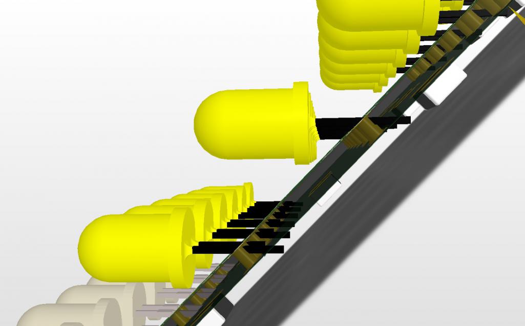
Posted by: swooshdave Jun 26 2014, 09:40 PM
Drill the holes at an angle?
Posted by: sportlicherFahrer Jun 26 2014, 09:48 PM
Rubber support strips under each row, or clear plastic epoxy on either the whole board or a bead on each individual LED?
Depending on how deep these are mounted in the bucket the housing may help reflection, and the lenses are fluted to help direct light. Not sure if anyone has played with the configuration yet to see.
Posted by: tomeric914 Jun 26 2014, 10:12 PM
Build a jig to prebend LED leads at a 45 degree angle and solder through the board normally?
http://www.kingbrightusa.com/ApplicationNotes/ApplicationNotesFor_Through-Hole_LEDs.pdf
Posted by: Spoke Jul 20 2014, 06:55 AM
Just about ready to fab the first prototypes of the front marker lights.
The board will have 3 options:
1) Euro: Cool white LEDs on the bottom on brightly with running lights; top amber LEDs on brightly with turnsignal, off with running lights.
2) Euro: Same as 1 except the amber LEDs on dimly with running lights.
3) US: All LEDs are amber; all on dimly with running lights, brightly with turnsignal.
Here's how the board looks now. There are a total of 69 LEDs. In Euro trim, 21 are cool white and 48 are amber. In US trim, all 69 are amber.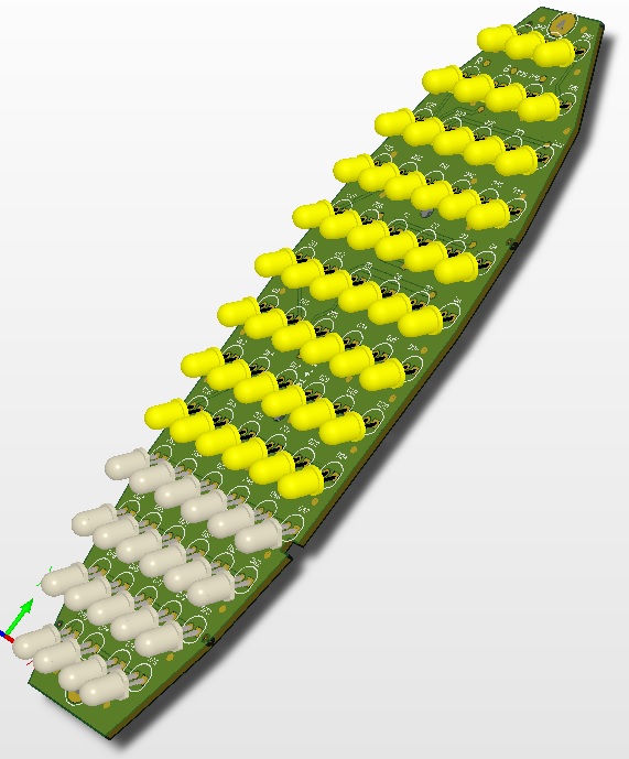
On the back of the board, notice how few resistors are behind the white running LEDs. This is done to spread out the heat emitting components for the running lights to keep the temperatures a low as possible.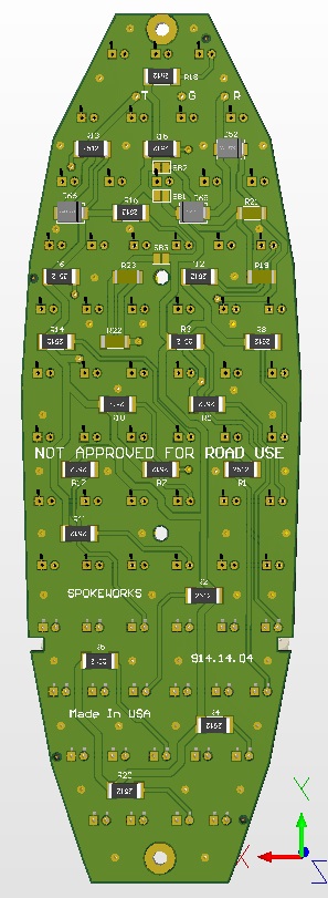
I did a mock-up with a piece of wood with a couple of LEDs mounted. This is about where the board will sit. At this time I'm leaning towards metal clips on each end of the board which will slide under the lens gasket and be held on by the lens screws.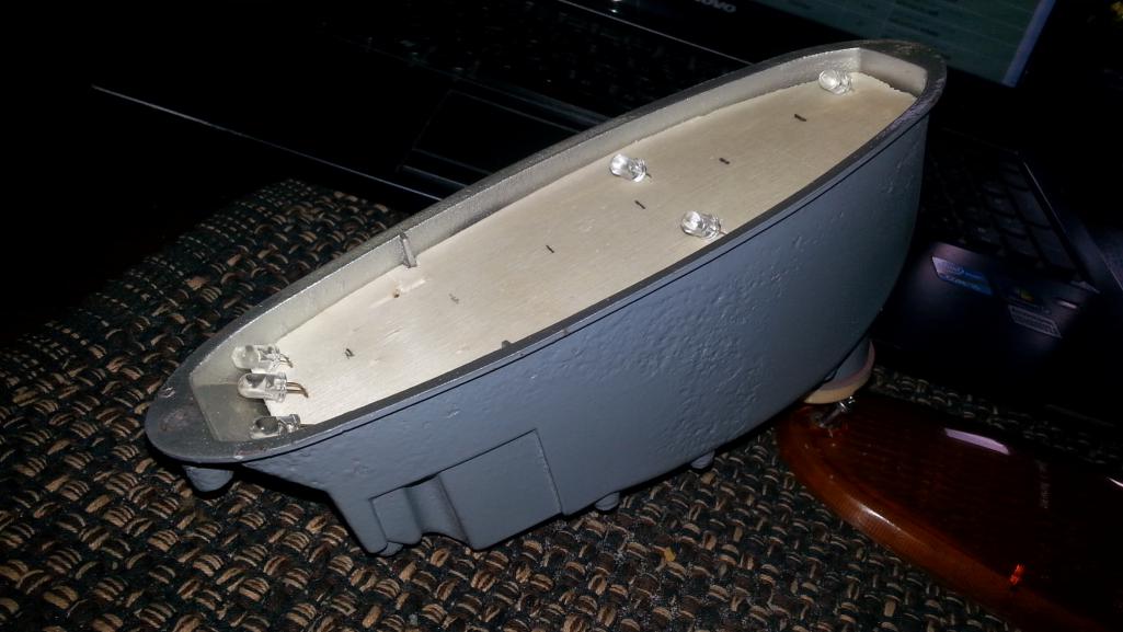
Posted by: cary Jul 20 2014, 07:44 AM
I'm in for a US version pair. Changed my mind, I'll take a Euro set. Way to cool.I'd like the blanking version. White off when flasher/turn signal is on.
Can we get them with amber and clear/white on when in the running/headlight mode?
Posted by: Zimms Jul 20 2014, 08:20 AM
I am in for option 2
Posted by: sportlicherFahrer Jul 20 2014, 08:24 AM
Still in for one set of option 1 please.
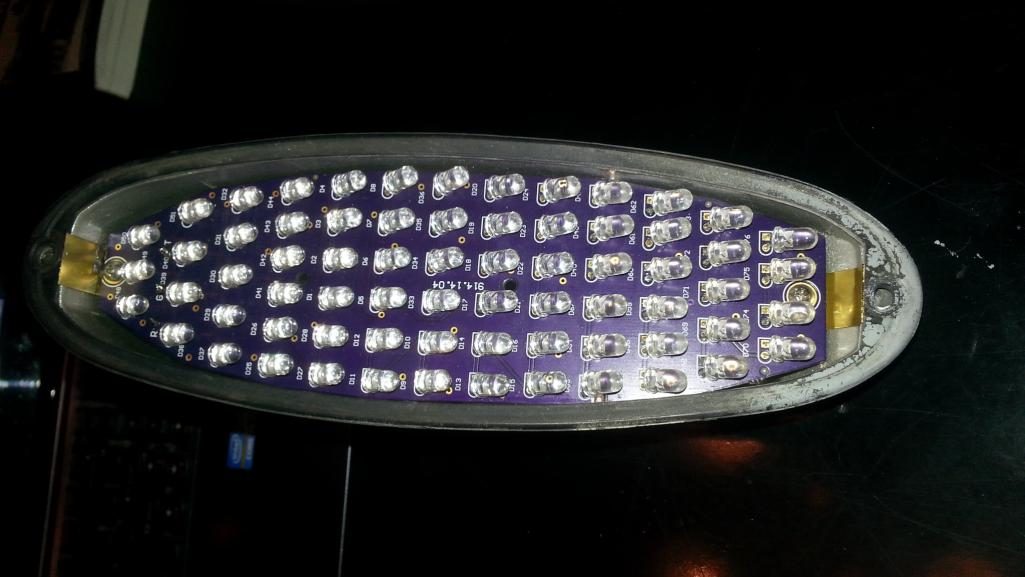
Posted by: Spoke Aug 4 2014, 10:03 AM
The first prototype boards arrived today. The fit is ok but will need some tweaks.
I'll build up the first units this weekend and see how they look.
Because the LED turnsignals may cause some interaction with the stock turnsignal flasher unit, I was thinking about adding an optional power resistor on a pigtail which then would sit in the base of the front bucket. The power resistor would make the flasher unit happy and eliminate any interaction with the LED lights.
Attached thumbnail(s)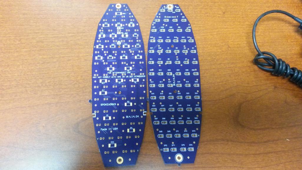
Posted by: JmuRiz Aug 4 2014, 10:14 AM
Very cool stuff, are you going to do one like in post #6...those would be great daytime running lights for clear lenses!
I'll keep watching this thread...once front is figured out I'll order some rears and fronts.
Posted by: 914Mike Aug 4 2014, 11:18 AM
This was posted in my LED brake thread. One picture says a lot.
While that may be true, matching the color is not always the desired outcome.
Case in point, rear Euro lenses on US housings. Most people just slap them on, not realizing that their rear tail lights and side markers have turned to amber, which is not exactly legal. I solved that on my '71 by putting red LEDs in those sockets, which color the amber lenses red until the amber turn signal LEDs flash.
Loss of brightness from the red LEDs was actually what I needed to balance the tail light and side marker against the turn signals. And it looks pretty cool too, all red in back like it's supposed to be, then the amber just completely washes out the red when blinking.
Posted by: Cairo94507 Aug 4 2014, 01:04 PM
Hi Spoke:
I am hoping that when Scotty is ready for lights in my car we will be able to buy one complete set, front/rear and side markers in LED.
Posted by: Harpo Aug 4 2014, 04:17 PM
Thanks for the update. Looks good
David
Posted by: GermermanCarGuy Aug 4 2014, 06:46 PM
Haven't made too much progress on the fronts.
There are 2 issues to work out with the mounting of the LEDs on this board. Given that the LEDs will be mounted such that they are at 45 (or so) degree angle from the board, I've been in consultation with the guys at work on how to mount the LEDs about 3/16 to 1/4 of an inch above the board, then bend all the leads so the LEDs all point in the same direction (toward the front of the car).
The second issue is how to secure the LEDs to the board as to take the stress of vibration off of the solder on the long leads. We're thinking the LED body will need to be glued, caulked, or conformal coated to the board.
 Referring to your "how to secure" issue... how about mounting the bulbs straight in to provide secure solder contacts, bend bulbs to 45 degrees for proper alignment, then add (front and/or back) a soft gel coat sealant similar to what AMC used on early 70's Jeep power control modules. With bulb tips protruding, the whole unit would be secured against excessive vibration and have a level of water-proofing. Drawback -- thickness.
Any thoughts of bundling fronts and rears (w/side markers as a 2-wire plug-in upgrade option) together. I'd be game for a complete set, Euro style please. I'd really like to add this upgrade to my build. Thanks
Posted by: mobymutt Aug 4 2014, 08:14 PM
That's one issue. The second is once the leads are bent, how to take the stress of securing the LED off of the soft solder on the leads. Eventually the vehicle vibration through the LED bodies will wear out the solder and the solder will fail. Somehow the body of the LED must be secured to the board by other mechanical means. Right now I'm thinking about conformal coating or caulking of some sort.
Any ideas on soldering the LEDs 3/16" off the board or securing the body to the board are welcome.
I know nothing about circuit board design, but that won't stop me from chiming in on this. BTW, I think both these lights and the LED tail lights are awesome, they are on my Christmas list.
First, I am not convinced that the vibrational stress on the soldered connections will really be all that different on the long bent leads vs the standard ones. That being said, I understand your concern, better to be safe than sorry!
What if you make a 3D printed support that follows the profile of the circuit board, but is stair-shaped in cross section -- this support piece would go between the LEDs and the circuit board, and provide secure support for the bulbs. Perhaps you could integrate the bucket mounting features into it as well. I can model something up if you think this idea has any merit, just PM me.
Posted by: mikesmith Aug 4 2014, 11:21 PM
Rather than bend the leads, just increase the drill size so that the LED sits naturally in the hole at the right angle. Build a jig to hold the board tilted so the LEDs flop over.
This would be a nuisance to set up if you were wave soldering (you'd want a different jig that secured the LEDs at the correct angle), but assuming you're still assembling these by hand (you masochist) it should be simple.
With this layout, the low side of the LED should be touching the board, so a generous coating of conformal will bind the LEDs to the board, giving you the mechanical strength you wanted.
Also, +1 for a set of the Euros.
Posted by: Steve Aug 4 2014, 11:34 PM
Depending on cost, I will take a set of Euro LED's.
Posted by: euro911 Aug 4 2014, 11:57 PM
please...

Nice
![popcorn[1].gif](style_emoticons/default/popcorn[1].gif)
Wouldn't it be more like this though, Rob ?
E
U
R
O

... and I'm in for a pair of EURO units of course
Posted by: CptTripps Aug 5 2014, 07:20 AM
If you're worried about vibration, you could always use a rubber grommet at the mount points.
These look awesome, and I'd love a set to match my tail lights too.
Posted by: Spoke Aug 5 2014, 11:31 AM
Thanks all for ideas on mounting the LEDs. We've been discussing this at work for a while and have come up with several solutions.
Here's one that we've kicked around. This would have a spacer jig to keep the LEDs a uniform distance off the board when soldering. The production jig would encompass all the LEDs at once.
This test piece is simply 2 layers of protoboard glued together. I did one LED row and it worked well. Just bent the LEDs until they contact the board.
Attached thumbnail(s)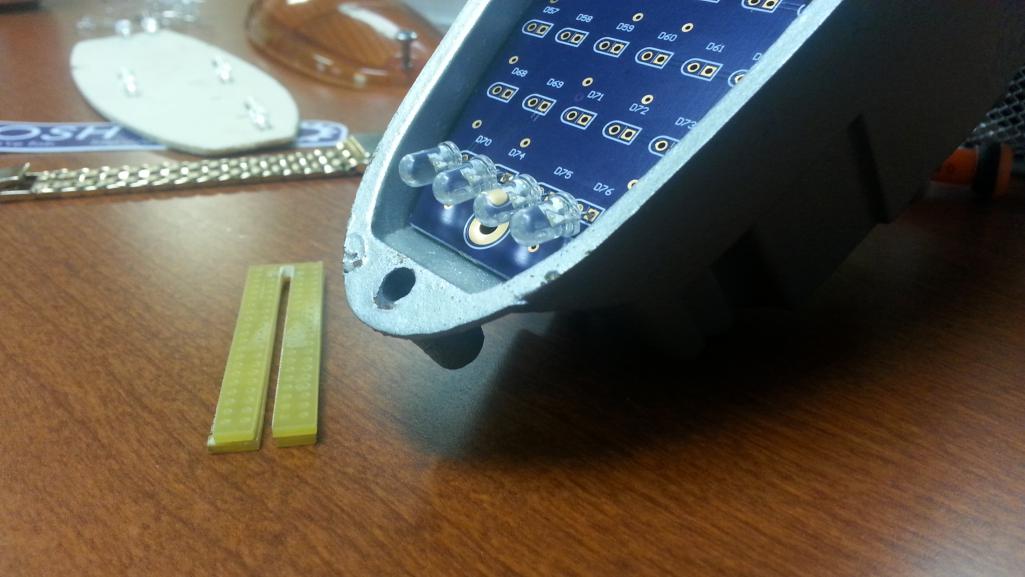
Posted by: kid914 Aug 5 2014, 02:33 PM
in for a US set. I still have to order the rears. 
Posted by: john77 Aug 5 2014, 02:35 PM
In for a set to go with my rears.
Posted by: eric9144 Aug 5 2014, 05:02 PM
In for a US set...
Posted by: Spoke Aug 8 2014, 10:01 AM
Built up the first prototype; except for 3 white LEDs; need to order more.
The jig to bend leads worked well although the angle was slightly too great so the top of the board needs to be deeper than the bottom. Need to adjust the jig so the board can sit flush in the bucket.
Attached thumbnail(s)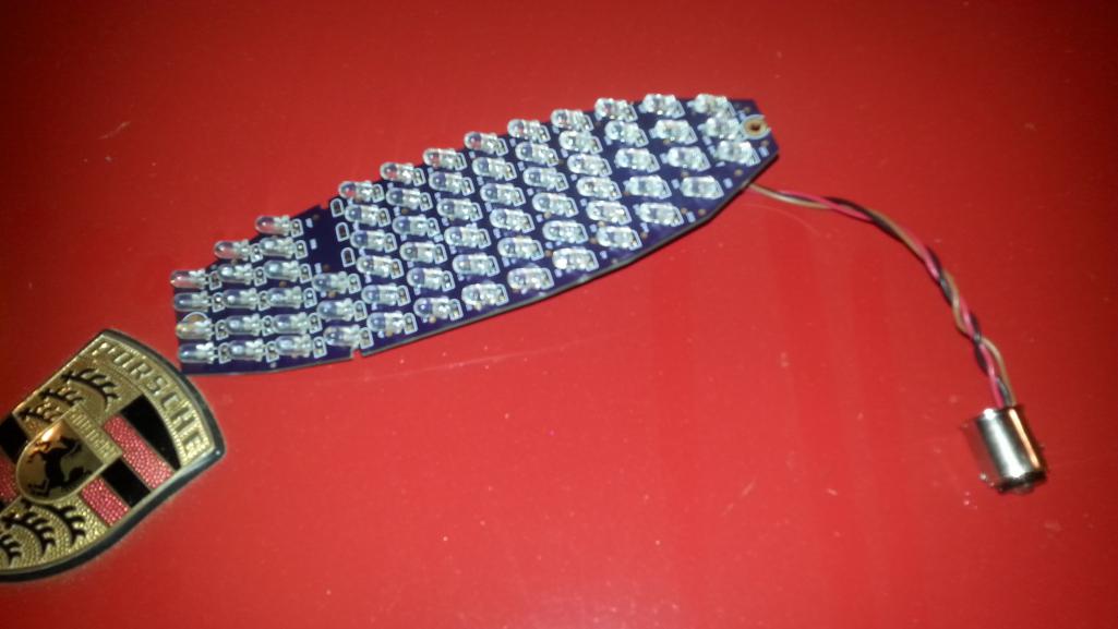
Posted by: euro911 Aug 8 2014, 05:25 PM
Jerry, if the upper end of the board sits further down in the bucket, why not just supply a stand-off and a long screw for the upper end? ... or am I missing something ?
Posted by: Harpo Aug 8 2014, 06:21 PM
Looks awesome Jerry +1 euro
David
Posted by: speed metal army Aug 8 2014, 10:38 PM
Yep! In for a set of fronts and rears as soon as the fronts are sorted. (euro fronts,rears)
Nice work. You have wayyy more patience than I do.
Posted by: Spoke Aug 10 2014, 09:06 PM
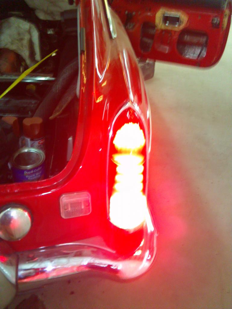
Took a couple of videos of the front LEDs. This is the Euro version.
First the turnsignals; then just the running light. For the turnsignal, the US lens is on. For the running light, the lens is removed.
https://www.youtube.com/watch?v=-Go4DQY5T3U
Now both the running light and the turnsignal with the US lens off.
https://www.youtube.com/watch?v=4y2HTTtBjG8
Posted by: JmuRiz Aug 11 2014, 11:51 AM
Is there anyway to turn the running light off when the turn signal is flashing?
The Audis do that, and it makes it easier to notice the flashing signal.
Either way, great progress.
Posted by: euro911 Aug 11 2014, 03:15 PM
In both video clips, are the driver side lamps the stock incandescent bulbs?
I notice a lag to full illumination, whereas the passenger side are a lot quicker and precise
As far as I'm concerned, the same safety factor applies to the fronts. If they are brighter and easier to see by opposing traffic, they are definitively worth the $ 
Posted by: Chris H. Aug 11 2014, 06:41 PM
Yep that's what it looks like. I just updated my original post...going US spec. When do you think these will be ready?
Posted by: IanS Aug 12 2014, 09:38 AM
Those look amazing! I think I already replied in this thread but if not I definitely want a set. I have a US amber front light and no side markers so I guess I would want the non-euro light but I really like the running lights feature.
Posted by: CptTripps Aug 12 2014, 10:06 AM
You know me...I'm in.
Posted by: Spoke Aug 12 2014, 03:33 PM
Jerry, if the upper end of the board sits further down in the bucket, why not just supply a stand-off and a long screw for the upper end? ... or am I missing something ?
I'm planning to mount these with brass sheet material like I started on the rear lights. I want to use the existing 2 screws for the lens cover to secure the board. As with the rears, the goal is to make no modifications, drilling, or wire changes to the bucket or lens.
I wanted the board to be flush with the bucket angle. This first pair will sit lower in the rear but will work just fine. Just doesn't look as nice as I would like it to. I need to make a jig that is slightly thinner than the one I used for the first board.
Posted by: Spoke Aug 12 2014, 03:36 PM
In both video clips, are the driver side lamps the stock incandescent bulbs?
I notice a lag to full illumination, whereas the passenger side are a lot quicker and precise
As far as I'm concerned, the same safety factor applies to the fronts. If they are brighter and easier to see by opposing traffic, they are definitively worth the $
Yes, the driver side bulb is a standard 1157 bulb. When looking at the flashing of the bulb, when the bulb turns off, its illumination dies quite slowly such that it is almost off by the time the flasher turns back on. The LED is just ON-OFF, no slow turn on or lagging illumination.
Posted by: Spoke Aug 12 2014, 03:41 PM
Is there anyway to turn the running light off when the turn signal is flashing?
The Audis do that, and it makes it easier to notice the flashing signal.
Either way, great progress.
I thought about adding the blanking feature but some folks mentioned they didn't like it so I left it off. It does simplify the circuit but it could be added if folks thought it is important to blank the running lights when the turn signal is on.
Posted by: db9146 Aug 13 2014, 12:21 PM
I'm in for a pair of Euros. Nice.
Posted by: mikesmith Aug 14 2014, 09:58 AM
I thought about adding the blanking feature but some folks mentioned they didn't like it so I left it off. It does simplify the circuit but it could be added if folks thought it is important to blank the running lights when the turn signal is on.
For folks that want it, there are a number of modules like this one:
http://modifry.com/products/smm/index.htm
that can easily be added if you want the functionality...
Posted by: Spoke Aug 15 2014, 02:09 PM
Couple more videos of the front LEDs. This is the Euro version.
First the turnsignals; then just the running light. For the turnsignal, the US lens is on. For the running light, the lens is removed.
I wanted to observe the angle of incidence on the LEDs. These LEDs have 15 degree 1/2 power angle. So for the turnsignals and running lights, I varied the angle of viewing from about +/- 45 degrees from the front of the car. I was about 30 feet away.
https://www.youtube.com/watch?v=KEIcKTeHoa0
Now the running light with the US lens off.
https://www.youtube.com/watch?v=1xe09_u_dSg
Posted by: Cairo94507 Aug 16 2014, 07:40 AM
WOW!  Those front LED's are terrific. If people can't see those lights they need a cane.
Posted by: Firstcar Aug 16 2014, 08:22 AM
Euro version with the white running lights looks great and is a good safety measure
(and I could stop running with the fogs on all the time). I think the blanking feature makes the turn signal more visible. Now how about an LED for the side marker wart that flashes with the turn signal!
Posted by: kid914 Aug 16 2014, 09:42 AM
First off, Spoke, you do awesome work at keeping US and our cars safe. Thank you.
It might still be too early, but would you have an idea on price?
or did I miss it. 
Posted by: siverson Aug 16 2014, 10:13 AM
Very nice. I'll be in for a set when ready.
And... are there already rears available? Did I miss that?
-Steve
Posted by: clapeza Aug 16 2014, 10:25 AM
I'm in for a Euro set, when available. Awesome work!
Chester
Posted by: rnellums Aug 17 2014, 10:30 PM
Not sure if I posted yet, but I love my rear LED's and would love a stock front set to match!
Posted by: CptTripps Aug 18 2014, 06:47 AM
As always....they look perfect.
I'm in for Euros when you have them ready. I'll gladly scrap the thing that I built already in favor of these.
Posted by: euro911 Aug 21 2014, 02:41 AM
First the turnsignals; then just the running light. For the turnsignal, the US lens is on. For the running light, the lens is removed.
I wanted to observe the angle of incidence on the LEDs. These LEDs have 15 degree 1/2 power angle. So for the turnsignals and running lights, I varied the angle of viewing from about +/- 45 degrees from the front of the car. I was about 30 feet away.
Now the running light with the US lens off.
Posted by: BuddyV Aug 21 2014, 08:12 AM
914 people are friggin awesome..... thank you for this.
I am in for two when you are ready.
BITCHIN!!!!!!!!
Posted by: Spoke Aug 21 2014, 09:12 PM
I'd like to ask a favor of anyone interested in the front LED turnsignals: Try this test: Remove one of the front turnsignal bulbs and see if the flasher still works. Also check the dash indicator. Let me know what you find.
A little background; with the rear LED turnsignals some folks have had issues with the flasher either not flashing or the dash indicator not working correctly.
The interaction issues with classic flasher units and the light loads of LED lights is well known in the automotive industry. 2 ways to solve this are replacing the flasher with LED-compatible flasher or adding load resistors in parallel with the LED lights. I would like to find a nice compromise which would require minimum rewiring.
Thanks!
Posted by: mikesmith Aug 21 2014, 11:06 PM
+1 for a LED-compatible flasher.
Posted by: Spoke Aug 23 2014, 05:56 PM
+1 for a LED-compatible flasher.
I only wish it were a simple change. The 914 uses the flasher for the turnsignals as well as the ebrake and MC warning flasher. It also has an output for the dash indicator(s) so they won't flash if the ebrake or MC is flashing.
If changing the flasher, one would have to replace the flasher, then rewire the dash indicator(s).
For the early tachs with L and R indicators, this as simple as grounding the wire going to the K output of the original flasher.
For late tachs with a single indicator, one would have to connect the indicator to both turnsignal wires (on the hazard switch) through a pair of diodes. The diodes would allow the indicator to light whether the R or L turnsignal is on.
If anyone has implemented an LED-compatible flasher, please share your work.
Posted by: mikesmith Aug 29 2014, 09:58 PM
If anyone has implemented an LED-compatible flasher, please share your work.
I have a no-name Chinese LED-capable EP26 flasher in a '72. It's a plug-and-play install, no wiring changes required.
I can't speak with authority about the 74+ cars, but the wiring looks comparable.
Posted by: lawnvett Aug 29 2014, 11:18 PM
If anyone has implemented an LED-compatible flasher, please share your work.
I have a no-name Chinese LED-capable EP26 flasher in a '72. It's a plug-and-play install, no wiring changes required.
I can't speak with authority about the 74+ cars, but the wiring looks comparable.
My wife and I are new here but please put us down on the list for LED UPGRADES front and back, these look good, the 914 is hers, I drive a MGBGT with a 3.4 V6 and I use LED boards in the MG, really helps our little cars to be seen!
Posted by: montoya 73 2.0 Aug 29 2014, 11:59 PM
Put me down for euro fronts and possibly a 2nd pair for clear lens.
Posted by: Spoke Aug 30 2014, 06:56 AM
I have a no-name Chinese LED-capable EP26 flasher in a '72. It's a plug-and-play install, no wiring changes required.
I can't speak with authority about the 74+ cars, but the wiring looks comparable.
Thanks Mike. Looks like AutoZone stocks this flasher. I'm going to pick one up and do some tests.
http://www.autozone.com/autozone/parts/Novita-Hazard-Warning-Flasher/_/N-5yc1s?itemIdentifier=247230
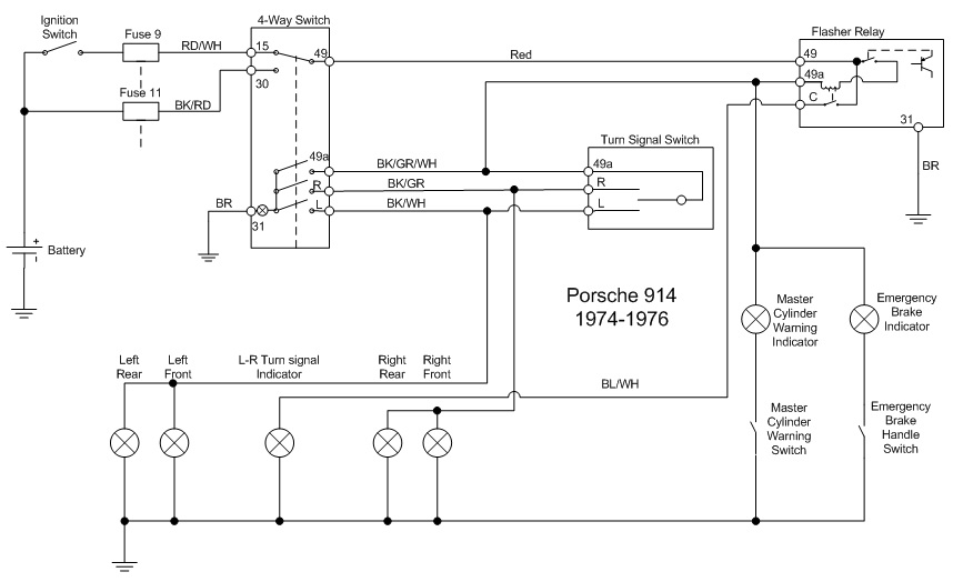
Good point about the 74+ cars. See the diagram below. The flasher is used to flash the brake warning light for the MC or ebrake. The light load of the brake indicator keeps the turnsignal indicator from flashing. With the EP26 on 74+ cars it would seem the turnsignal indicator would flash with the MC or ebrake indicator.
Attached image(s)
Posted by: Spoke Aug 30 2014, 10:26 PM
I picked up an EP26 flasher today at my FLAPS. It is rated for LEDs and 2-6 lamps.
I found it would not blink with just one of my front bucket LEDs on it. When open circuited (no load), 49A which goes to the turnsignal bulbs was sitting at about 7.5V with 12.6V applied to the flasher.
At 7.5V, the LED board does not have any current draw. The LEDs need about 8.4V to start turning on.
I did find that with a load of at least 4k ohms, the flasher would flash normally. This is about only 3ma load. Still need to study this a bit more.
Posted by: orthobiz Aug 31 2014, 09:45 PM
A long thread. So the final product is not ready to purchase yet, right??
Paul
Posted by: Spoke Sep 1 2014, 06:26 PM
A long thread. So the final product is not ready to purchase yet, right??
Paul
Still working out some issues.
At this point, 2 items need to be ironed out:
1) Blanking: several folks had shown interest in a blanking circuit for Euro lenses such that the white running light turns off when the turnsignal is activated. This is done with many late model vehicles with running lights near the turnsignals.
I have a circuit to do this so I will run a couple more boards with this circuit to test it out.
2) Compatible flasher: For those with front and rear LED turnsignals, it is most likely that the standard flasher will either hyperflash (flash real fast), not flash at all, or not flash the dash indicator. Front LEDs aren't too useful if the flasher doesn't flash.
I've tested one flasher (EP26) and it works well only a minimum 4k ohm resistor is across the LED turnsignal.
Posted by: Spoke Sep 17 2014, 12:19 PM
I'm still testing flashers. Found an EP36 LED-compatible flasher at AutoZone.
http://www.autozone.com/autozone/parts/Novita-Hazard-Warning-Flasher/_/N-5yc1s?itemIdentifier=6417
This one works well with the front LED board without any load resistors. It does not have the K or C spade for the dash indicator light. It has 49 (Battery), 49a (lights), and 31 (ground).
As far as the blanking is concerned, I have a circuit designed and the board laid out. I will run a couple more of these boards to test the blanking.
Still working on the clips for the front buckets. should be just like the rear lights and require no mechanical changes to the bucket.
Attached thumbnail(s)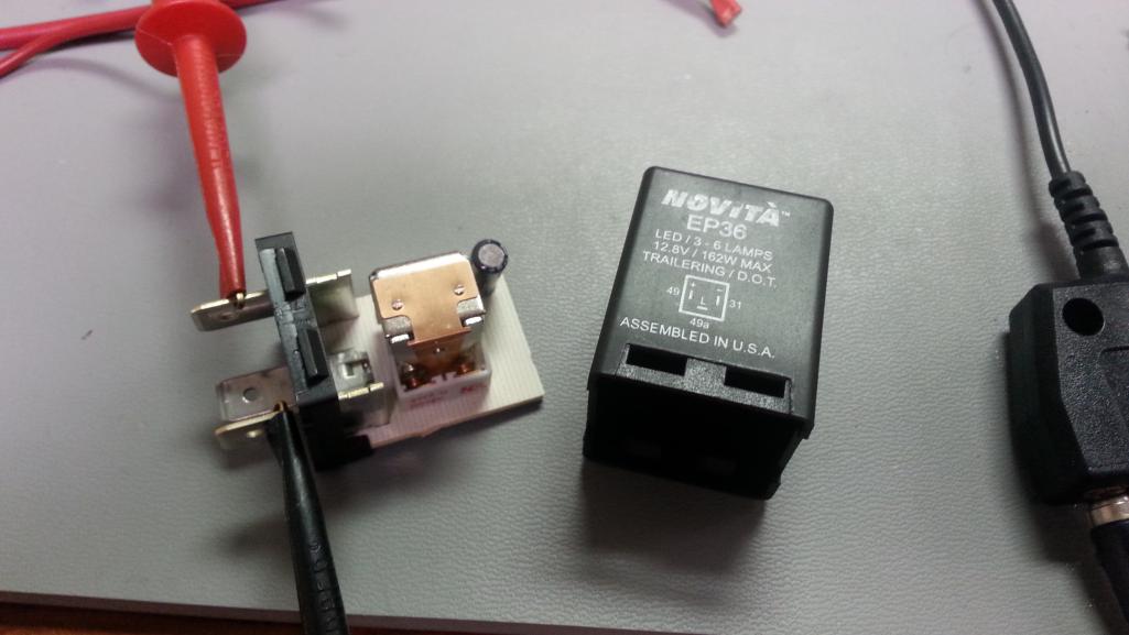
Posted by: Spoke Sep 17 2014, 12:47 PM
Double Post; Post whore.
Posted by: Spoke Sep 17 2014, 12:48 PM
About the flasher, I haven't found any flashers with the K/C spade for the dash light. The workaround for this is different for early and late gauges.
For early gauges with L & R indicators, the common wire will be taken off of K and tied to ground. For the later gauges with one indicator, that wire will be connected to the 49a lead.
Posted by: Gary Sep 18 2014, 07:21 PM
About the flasher, I haven't found any flashers with the K/C spade for the dash light. The workaround for this is different for early and late gauges.
For early gauges with L & R indicators, the common wire will be taken off of K and tied to ground. For the later gauges with one indicator, that wire will be connected to the 49a lead.
Would the CF18-08 on https://www.superbrightleds.com/search/led-products/flasher/ help? It has a turn signal spade.
Posted by: Spoke Sep 22 2014, 08:37 PM
Would the CF18-08 on https://www.superbrightleds.com/search/led-products/flasher/ help? It has a turn signal spade.
Thanks. Looks like that one may work but it does not have the same spade connectors as in the 914. I'm trying to make this as easy as possible to change out the relay with a replacement that could connect to the existing connectors.
Posted by: Spoke Sep 22 2014, 08:50 PM
Yet another update.
I've added a circuit to blank out the running lights for Euro lens configuration. Here's the circuitry added to do the blanking. Not seen in this view are the 2 TVS (Transient Voltage Suppression diodes) needed to protect this circuitry.
I'm running a couple more prototypes to make sure the circuit works as designed.
The circuit works like this: a comparator senses the turnsignal voltage and turns off the running lights. An RC discharge circuit keeps the running lights off between the blinking of the turnsignals.
The timing of the RC circuit keeps the running lights off for about 1 second after the last turnsignal blink. This is slightly different from modern autos since they have overall control of the lights and can turn on the running lights as soon as the turnsignal arm is released. This application will have about a 1 second delay till the running lights come back on.
The comparator makes the on/off transition of the running LEDs instantaneously. The comparator controls a FET which does the actual LED current switching. 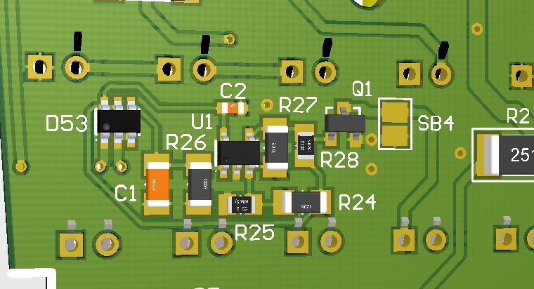
Posted by: Firstcar Sep 22 2014, 09:04 PM
Yet another update.
I've added a circuit to blank out the running lights for Euro lens configuration. Here's the circuitry added to do the blanking. Not seen in this view are the 2 TVS (Transient Voltage Suppression diodes) needed to protect this circuitry.
I'm running a couple more prototypes to make sure the circuit works as designed.
The circuit works like this: a comparator senses the turnsignal voltage and turns off the running lights. An RC discharge circuit keeps the running lights off between the blinking of the turnsignals.
The timing of the RC circuit keeps the running lights off for about 1 second after the last turnsignal blink. This is slightly different from modern autos since they have overall control of the lights and can turn on the running lights as soon as the turnsignal arm is released. This application will have about a 1 second delay till the running lights come back on.
The comparator makes the on/off transition of the running LEDs instantaneously. The comparator controls a FET which does the actual LED current switching.
Can't wait to see your video of the finished board with a Euro lense! Really great design. I'm looking forward to going all LED.
Posted by: Spoke Sep 22 2014, 09:11 PM
I've located 2 LED-compatible flasher relays that work with the front/rear LEDs.
When some folks replaced their rear turnsignal bulbs with LEDs, they experienced some flasher issues from not blinking at all to the dash indicator lamps not flashing. This incompatibility of older flasher relays with LED replacement bulbs is well known in the automotive arena.
When the front turnsignal bulbs are replaced with LEDs, the 914 flasher may or may not work. The 914 flasher may have to be changed to use the front LEDs especially if there are LEDs on the rear turnsignals.
The goal to changing the flasher is to make it as simple as possible. No wire cutting or splicing, simply pull the old flasher and install the new flasher. This will still be a pain in the ass as the flasher sits above the fuse panel and the fuse panel will need to be lowered to do the swap.
Because early/late tachs have different indicator bulbs (early has L & R; late has a single bulb), different flasher functions are necessary.
The EP36 is available at AutoZone and AdvanceAuto and would be used for early tachs. This one has power (49), turnsignal lamp (49a), and ground (31). There will be a wire change although because the EP36 does not have a K/C output like the 914 flasher. Thus the common wire from the dash indicators would be attached to ground on the flasher. A 3-way adapter will allow the normal ground and dash indicator common to both connect to the 31 lug.
The FL3-RED is available online at superbrightleds.com and would be used for late tachs with a single dash indicator. This flasher has a "P" connection which is for the "Pilot" or dash indicator. Interestingly this flasher does not have a ground connection. I tested this flasher with my front LED board and it does work.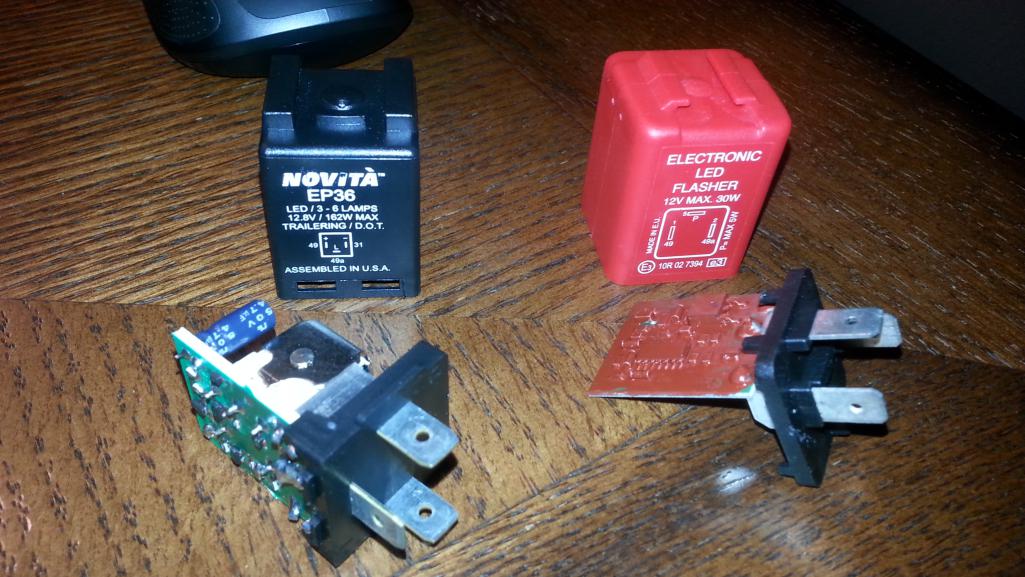
Posted by: StratPlayer Sep 23 2014, 04:33 PM
So the late model cars need to purchase the red flasher in order to get the front lights to work properly correct?
Posted by: Vacca Rabite Sep 23 2014, 06:46 PM
This is way cool. When my car is closer to being done and I order my rears, I'm going to want a set of fronts as well.
Zach
Posted by: mepstein Sep 23 2014, 07:40 PM
Another cool thing to add to the build list. Sigh....
Posted by: Spoke Sep 23 2014, 08:13 PM
So the late model cars need to purchase the red flasher in order to get the front lights to work properly correct?
I'm not sure what will happen when front and rear are LEDs. If someone installs the LEDs, I need to make sure they will work properly. One can pre-test the functionality of their flasher by removing any bulbs that will be replaced by LEDs. This will simulate a very light load. If everything flashes correctly, then no changes need to be made.
The 914 flasher relay doesn't flash the dash indicator under light load which is what happens when the ebrake is pulled or MC warning switch is active.
Posted by: Spoke Sep 23 2014, 08:15 PM
This is way cool. When my car is closer to being done and I order my rears, I'm going to want a set of fronts as well.
Zach
Let me know when I can start holding my breath on this one.

BTW, I will be offering the rear LED boards as well as the front LEDs.
Posted by: chads74 Sep 24 2014, 07:36 AM
I am excited to add the front LED's with the rear that are already installed. Rear are working great, I love driving at night and seeing the road lit up behind me.
Posted by: Spoke Oct 4 2014, 04:01 PM
I think I finally have a clip design that should work well for the front LEDs. This prototype is made out of brass but the production clip will be plastic.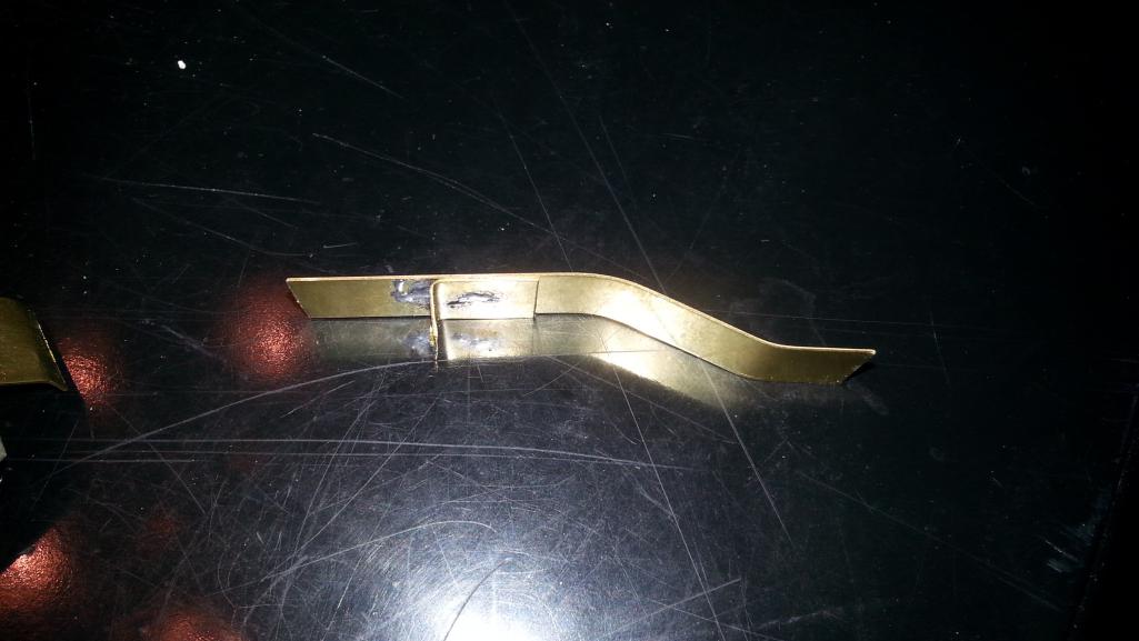
The idea of this clip is to have the clip span the entire depth of the bucket and be held in place with the lens cover. The board will screw onto the shoulder.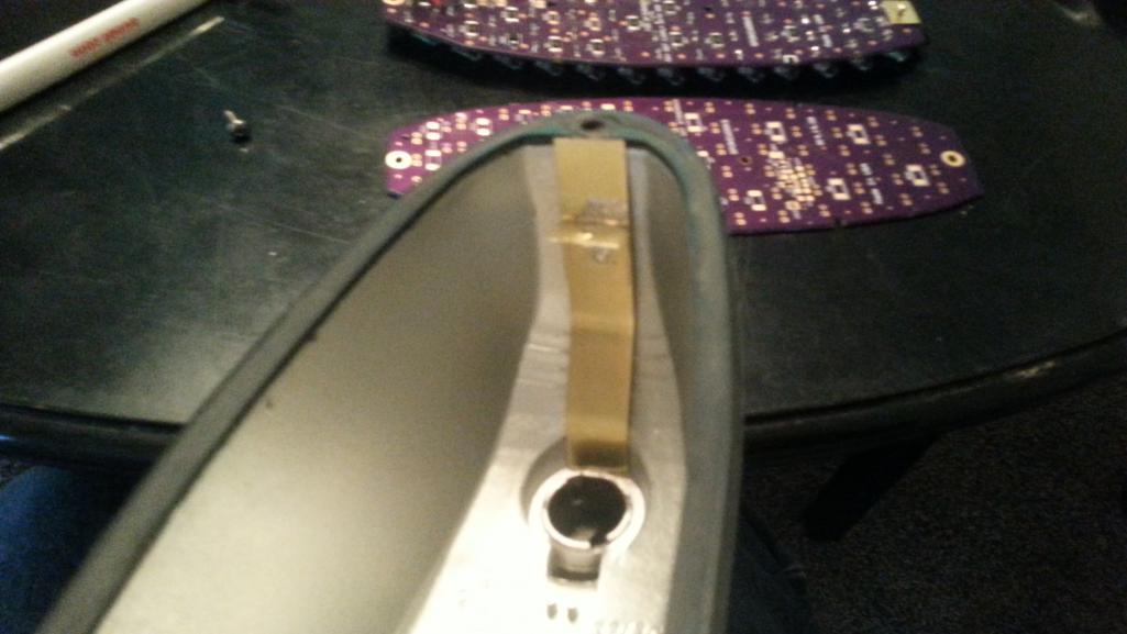
Like the rear LED boards, this one you will screw the clips to the board then insert the board in the enclosure.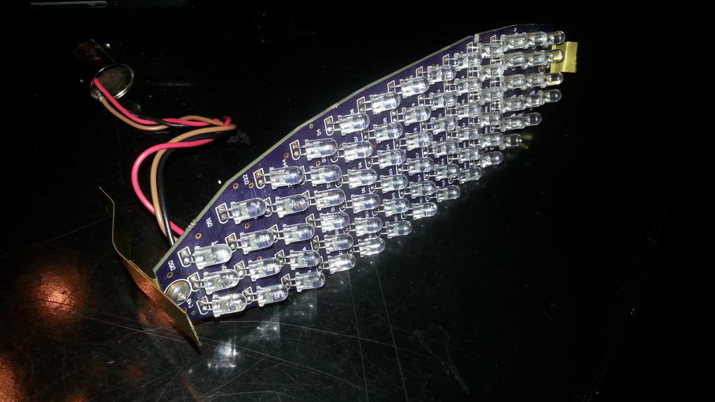
Posted by: Spoke Oct 4 2014, 04:04 PM
I've got the 2nd prototype board with the blanking circuitry. The blanking circuitry is the jumble of pads that can be seen on the bottom board between the notches in the board.
I'm getting the components next week from Digikey and will build up and test the boards.
Attached thumbnail(s)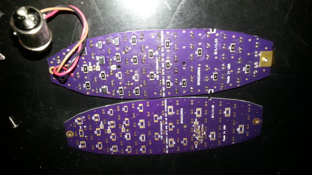
Posted by: Spoke Oct 4 2014, 04:08 PM
I was following this Nissan (with LED taillights) the other day and I noticed one of the LEDs was out.
So much for the propaganda we hear about 50k + hours of lifetime for LEDs. I kinda doubt that you could change just one LED in the array. I could be wrong though.
Attached thumbnail(s)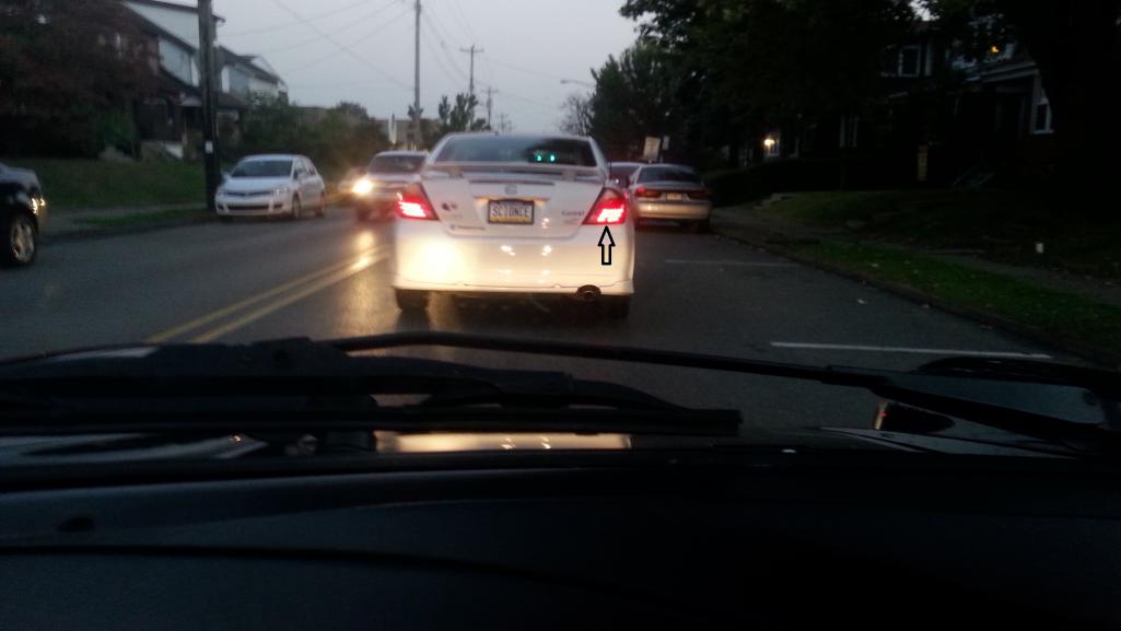
Posted by: mikesmith Oct 4 2014, 09:59 PM
The LEDs last forever. Solder joints, not always so long. 8)
Posted by: euro911 Oct 6 2014, 12:31 AM
With some of the asshole [anything for revenue] cops around here, I'd be worried that they'd write me up for having one burned-out LED out of the whole array
Posted by: Spoke Oct 9 2014, 11:01 PM
Built one of the front LEDs with running light blanking. Pretty much works as designed. The running lights cut out immediately when the turnsignals light and stay off about 1 second after the turnsignals turn off.
Here's a close up of the blanking circuitry.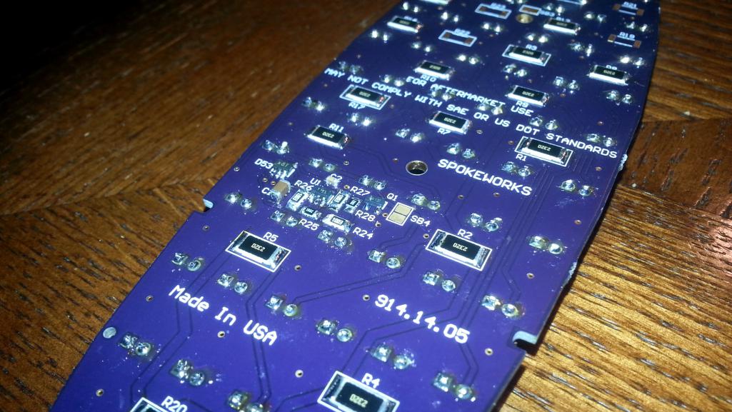
https://www.youtube.com/watch?v=RRBFT2LwVhc
Posted by: abnrdo Oct 9 2014, 11:06 PM
When your ready, I want a front set just like that! That rocks!!

Posted by: Spoke Oct 9 2014, 11:36 PM
This board fits much better in the bucket than the first protos.
Been working on a price for these boards. Looks like the price for a pair of the Euro LEDs will be $140 and the US version will be $120.
I tried to keep the price as low as possible but these boards are much more difficult to assemble than the taillights, have more LEDs than the tails, and a larger PCB. The biggest difference in price between the Euro and US is the cost of the white LEDs. The white LEDs are double the price of the amber or red LEDs. The blanking circuit adds a bit but not much.
Once we get some plastic clips made and tested, then the height of the board can be verified since the clips will have some thickness to contend with. Hope to do that within the month.
When we're ready to make the front LEDs, we'll also offer the taillight LEDs as well again. The price for those will remain at $90/pair for brake and turnsignal.
Attached thumbnail(s)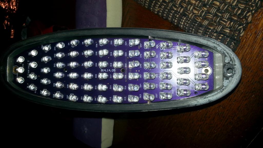
Posted by: Sleepin Oct 9 2014, 11:41 PM
Very nice! I am looking forward to these!
Posted by: euro911 Oct 10 2014, 01:53 AM
Cool
You're powering it from an 'N' gauge train track
Posted by: Cairo94507 Oct 10 2014, 05:06 AM
I definitely will want a set of the fronts like that and the rears. Will you make an LED side marker? These rock and will really be a nice modification to our cars to help make them safer.
Posted by: RobW Oct 10 2014, 07:39 AM
I'm in for F&R. Probably 2 sets. Whichever one is cooler between US and Euro.
Thanks for doing this!
Posted by: siverson Oct 10 2014, 12:05 PM
Ship it already! I want one set!
-Steve
Posted by: madmax914 Oct 10 2014, 02:12 PM
I want a set of US fronts and a set of rears. Will you be taking orders off of this thread or will you offer them in Classifieds? Possibly start a website?
Posted by: Harpo Oct 10 2014, 02:56 PM
Awesome sign me up for a set of euro's
DAvid
Posted by: Spoke Oct 10 2014, 10:59 PM
Will you make an LED side marker?
I haven't considered the side marker. I'm working on brake lights for my 911 right now.
Will you be taking orders off of this thread or will you offer them in Classifieds? Possibly start a website?
I'll start a group buy thread when we're ready. Haven't considered a website. We make these one at a time by hand so we can't do too many at one time so it's first come first served. I consider folks who respond to this thread with interest as first in line.
You're powering it from an 'N' gauge train track
It's HO gauge. My uncle started this layout in the '60's at his home in West Mifflin outside of Pittsburgh. He passed away in '87 and willed the layout to me. I moved it from his house to my house in Reading, PA; then to my house in Allentown.
The power supply for the rails is perfect for testing the LEDs. It outputs up to 20Vdc at 1.5A.

Posted by: euro911 Oct 11 2014, 12:50 AM
Nice layout! I used to work with 'N' gauge, but nothing that elaborate.
I bought some 'Z' gauge stuff and still want to do a small layout (under a glass coffee table top) ... project # 2,877 ...
Posted by: Firstcar Oct 11 2014, 07:13 AM
Spoke, Definitely interested in a set of the front Euros w/ blanking. Great job!
Posted by: Nutter965 Oct 23 2014, 04:38 AM
Spoke, i'd like to use the US red rear lenses but with a euro lighting colors etc, any idea how well the amber shows up through the red ?
Posted by: cary Oct 23 2014, 09:08 PM
Finally installed my rear LEDs.
Flasher works perfect.
Posted by: rdauenhauer Oct 23 2014, 09:40 PM
Enough lurking! Consider me down for front & rears!
Posted by: Spoke Oct 30 2014, 09:02 PM
Spoke, i'd like to use the US red rear lenses but with a euro lighting colors etc, any idea how well the amber shows up through the red ?
The amber comes through the red lens ok but there is some loss of intensity. I did a little video to show the difference. Not sure if it's helpful. What's the reason for running amber LEDs behind a red lens?
https://www.youtube.com/watch?v=ZwUs5VGk28U
Posted by: Spoke Oct 30 2014, 09:42 PM
Quick update:
The front LED board with blanking works fine. We're trying out plastic clips now. Once the clips work with the boards, we should be ready to run.
The LEDs will have to be secured to the boards with RTV. They are way too easy to bend out of shape without some securing material.
We should be ready to start in a couple of weeks.
Posted by: StratPlayer Oct 31 2014, 08:11 PM
Cool
Posted by: Spoke Oct 31 2014, 09:24 PM
I'm done with the first and only set of prototype Euro LEDs w/o blanking.
The running lights on this set stays on all the time that parking/head lights are on regardless of the turnsignals. No running light blanking.
I'll sell this one and only Euro w/o blanking prototype set for $85 + $10 shipping (CONUS). Respond to this thread if you're interested and I'll PM you with details.
Posted by: Harpo Nov 1 2014, 11:09 AM
I will take them
David
Posted by: Nutter965 Nov 1 2014, 11:11 AM
Spoke, i'd like to use the US red rear lenses but with a euro lighting colors etc, any idea how well the amber shows up through the red ?
The amber comes through the red lens ok but there is some loss of intensity. I did a little video to show the difference. Not sure if it's helpful. What's the reason for running amber LEDs behind a red lens?
https://www.youtube.com/watch?v=ZwUs5VGk28U
It would tie in nicely with my 965 it has (as they all do) full red rear lenses but the indicators show through amber as per normal, I do have a set of both lenses on for the road and one for the MOT over here, the better the amber shows the less I'll attract attention from the police
Posted by: Spoke Nov 4 2014, 12:42 PM
Made some plastic clips for the front LEDs.
These will work different than the rear LEDs as the lens will hold the clips in place. There is virtually nothing to clip onto in the front buckets so these will rely on gravity and the lens in place.
Also in the background is a board with RTV applied to hold the LEDs in place. The RTV isn't as solid as I would like but I haven't found anything else better to use.
Attached thumbnail(s)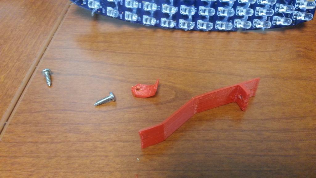
Posted by: Spoke Nov 4 2014, 12:49 PM
Installation should be easy.
The long clip goes in the back and the small clip goes in the front.
Notice the small clip mounts to the top of the board and its screw comes up from the bottom. The reason for this is twofold; one so the board itself will contact the beveled part of the housing and help keep the board straight, and the screw, if screwed in from the top, would hit the beveled part of the housing.
Both clips should be secured before installing the board.
Posted by: Spoke Nov 4 2014, 01:02 PM
Once the clips are attached, the board is ready for installation.
First is to plug the board in to the existing socket. Push in the bulb base with the tip of your finger and twist until seated. The bulb base should go in easily. It might be worthwhile to practice with the existing bulb.
These sockets are 40+ years old and may have a buildup of crud and oxidation. Clean the socket if necessary and use a small amount of lubricant like petroleum jelly to make sure the bulb installs easily.
Posted by: Spoke Nov 4 2014, 01:08 PM
Once the board is plugged in, make sure the wire stays out of the way of the rear clip when installing.
Position the front of the board first. There are slots in the board that fit into the ribs of the bucket.
Make sure the board is flush with the front and lower the rear of the board until the clip seats. Try not to push on the LEDs. Push on the clips if some force is necessary to seat the board. If you have to remove the board to reposition, do not grab the LEDs. Use a paper clip and get behind the board to remove it.
Install the lens.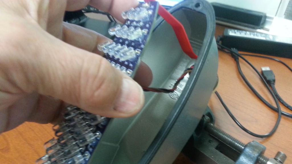
Posted by: montoya 73 2.0 Nov 4 2014, 01:52 PM

Posted by: Kansas 914 Nov 4 2014, 01:54 PM
I am in when these are ready - I have clear lenses up front but these should be fine.
Love the DRL!
Posted by: Cairo94507 Nov 4 2014, 02:25 PM
That is really nice. I hope you work your way around the whole car so we can replace all the exterior lighting with LED's.
Posted by: euro911 Nov 4 2014, 03:06 PM
Jerry, are you still going to produce the non-blanking style?
Posted by: Spoke Nov 5 2014, 11:16 AM
Jerry, are you still going to produce the non-blanking style?
Yes, the board is set up to bypass the blanking circuit. Price will be $130 ($10 less than blanking boards)
Posted by: euro911 Nov 5 2014, 01:29 PM
Cool 
Ready when you are
Posted by: charliew Nov 6 2014, 01:13 PM
I will take a US non-blanking set.
Posted by: CptTripps Nov 6 2014, 01:14 PM
I'm in too...
Posted by: Spoke Nov 21 2014, 12:19 AM
Bought a light meter to better analyze the output of the lights. Seems to work pretty well.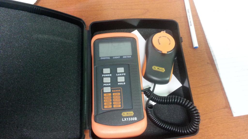
The first lights I looked at where these ones for my 930. They are similar to the 914 brake lights but with 48 LEDs vs 56 LEDs on the 914 brake.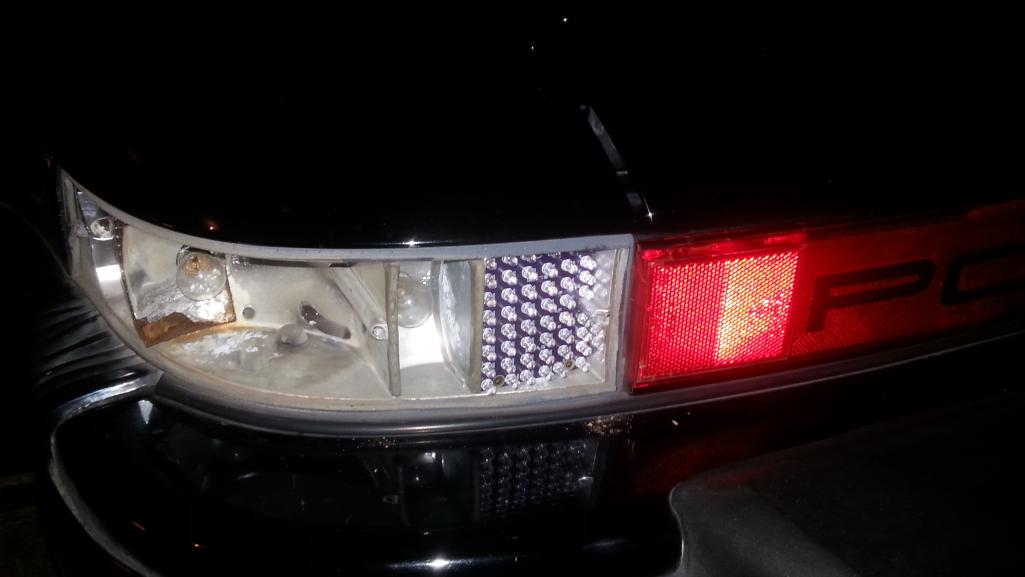
I measured the light output in LUX on the standard bulb and the LED board from about 4 ft away in the garage at night. The opposite light, the center brake light, and the license plate lights were covered up. I measured at 3 angles: 0, 15, and 30 degrees.
Here is the comparison of the 930 taillights. The LED drops off pretty quickly from center but starts at a much higher intensity. This focused intensity of the LEDs was pointed out by some folks.
However, the center relative intensity of the LEDs (directly behind vehicle) for the taillights is over 6x that of the bulb.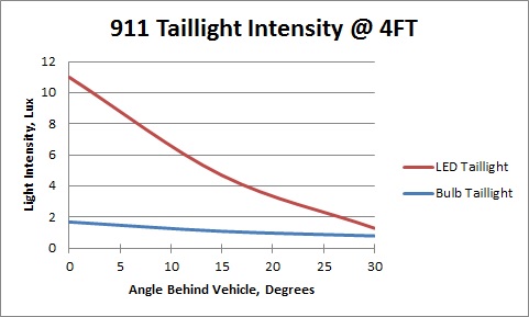
This is a comparison of the brake lights on the 930. Here the same profile is evident. Directly behind the vehicle the relative intensity of the LEDs is 3.5x that of the bulb.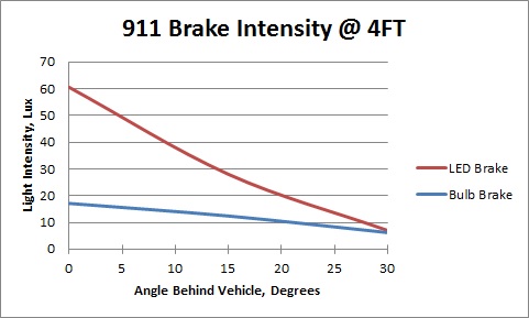
I tried to put this information into a format which would directly relate to the light pattern behind the vehicle. This graph shows the brake light pattern as viewed from above the vehicle. The intensities are 1x, 2x, and 3x of the standard bulb.
The driver directly behind the vehicle would see 3x intensity of the bulb.
A driver in the next lane at 10FT left or right from the vehicle about 25FT behind the vehicle would see an intensity about 2x of the standard bulb. This assumes the driving lane is 10ft wide.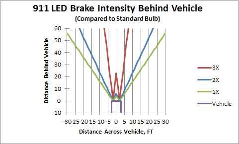
Posted by: Kansas 914 Nov 21 2014, 08:53 AM
Bought a light meter to better analyze the output of the lights. Seems to work pretty well.
That is great data. The key is even with a more drastic drop off the output of LEDs stay above that of the bulb at all times (if I read you right).
Well done.
Posted by: peteyd Nov 21 2014, 09:50 AM
Can I get a set of US blanking please.
Pete
Posted by: monkeyboy Nov 21 2014, 09:54 AM
I will take a set of US with the blanking please.
Posted by: aharder Nov 21 2014, 04:33 PM
I'm in for a set of US Blanking
Posted by: euro911 Nov 21 2014, 06:06 PM

Posted by: griffindoug Dec 1 2014, 08:33 PM
I will take a set of US with the blanking please.
I would like to get my grubby little hands on set of F&R LEDS. SPOKE, the work you have done here is appreciate by so many. I have been following this thread for a long time and am finally ready to buy up a set when you have them for sale. Please PM me with details to purchase.
Thanks
Posted by: monkeyboy Dec 2 2014, 10:04 AM
Marginally better than blacking out.


Posted by: Spoke Dec 18 2014, 11:47 PM
An update: It is finally on! 
Front and rear boards have been ordered with expected delivery 1st week of Jan. Will be ordering parts next week and should start building 2nd week in Jan.
As before, we'll work through PM's and a group buy thread to be created. I won't do a website or other mass purchase procedure as these boards are assembled one by one and we can't handle more than a couple folks at a time. No funds will be requested/accepted until we can build your boards. To speed up the process, I have a colleague lined up to build boards with me.
The only thing that is "group buy" about this process is the boards have to be purchased in quantity. Assembled boards take a lot of time and I try to keep the time between payment and shipping to a minimum. Even then it's still about 2 weeks between payment/shipping.
Purchase/building will be done first come-first served. I'll start with folks who PM'ed me before and/or responded to this thread first. We just can't build quantities of these boards fast so please be patient.
Posted by: Spoke Dec 18 2014, 11:55 PM
3 pairs of the prototype front LEDs have been install in 914's so far. This includes mine and 2 others.
Here's some pics from mikesmith's install. He has the euro lens and his boards do blanking of the running lights when the turnsignals are on.
All that is needed for install are a screwdriver (here a large phillips head for the lens and small one for the board screws) and maybe a or 2.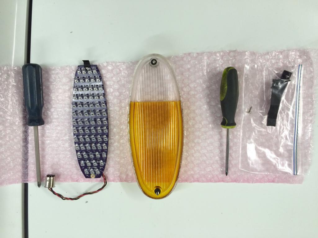
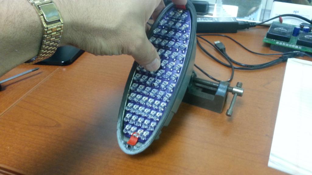
The board with both clips attached. The attachment of the front board was more complex than the rears. This PCB won't actually clip in but be held in position by the clips.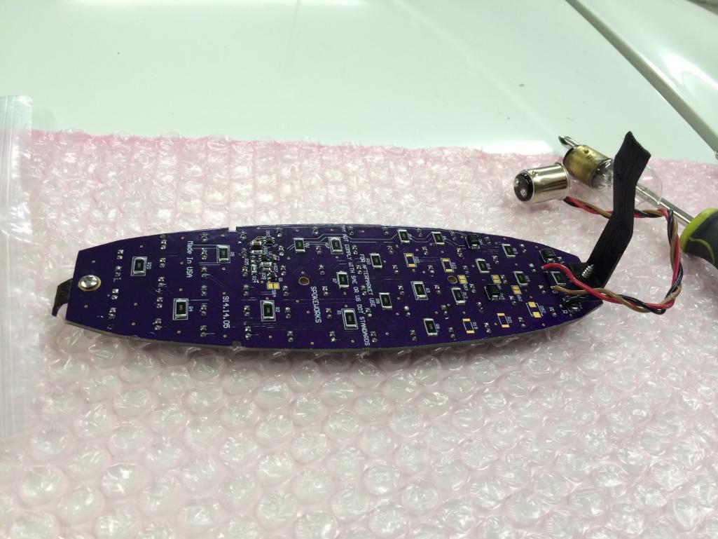
The bulb base is installed to the original bulb location. One thing we'll try to resolve is the difficulty installing the bulb base to the socket. These sockets tend to get really oxidized with a lot of crud build-up making the install difficult. A couple of folks had issues with the rear bulb bases.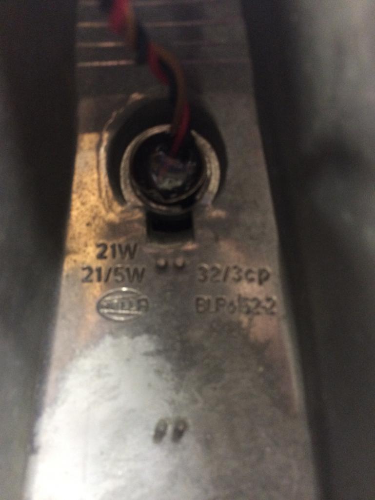
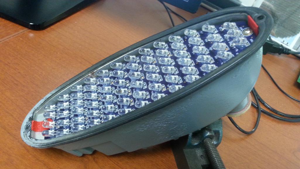
The board is installed. The top clip basically holds the board at the correct height and the bottom clip helps keep the board level by exerting pressure on the board to the bucket when the lens is attached.
Notice the RTV applied to each LED to absorb some of the vibration and to keep the LEDs in place during shipping and installation.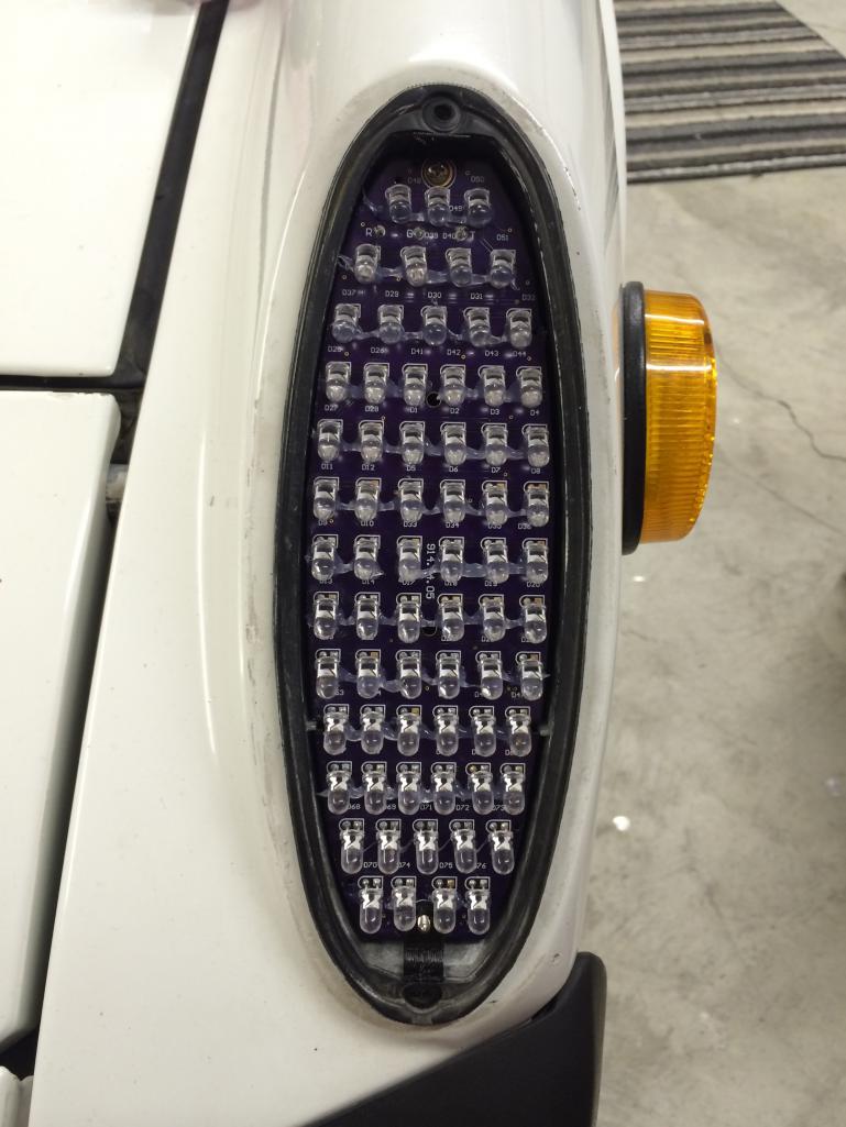
Posted by: Spoke Dec 19 2014, 12:08 AM
A comparison of the original bulb and the LED board. Light comparisons are difficult to convey with pics since cameras tend to auto-balance the shutter speed based on the light received and the light output of LED are extremely directional.
The original bulb in running light setting: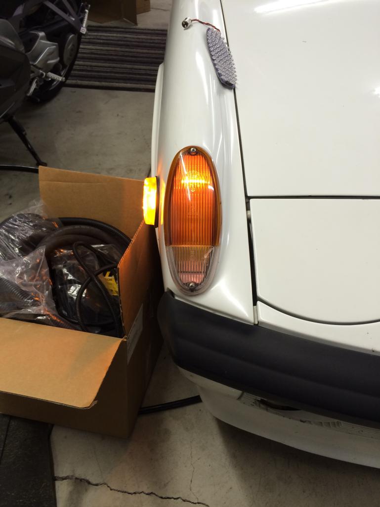
The LED running lights: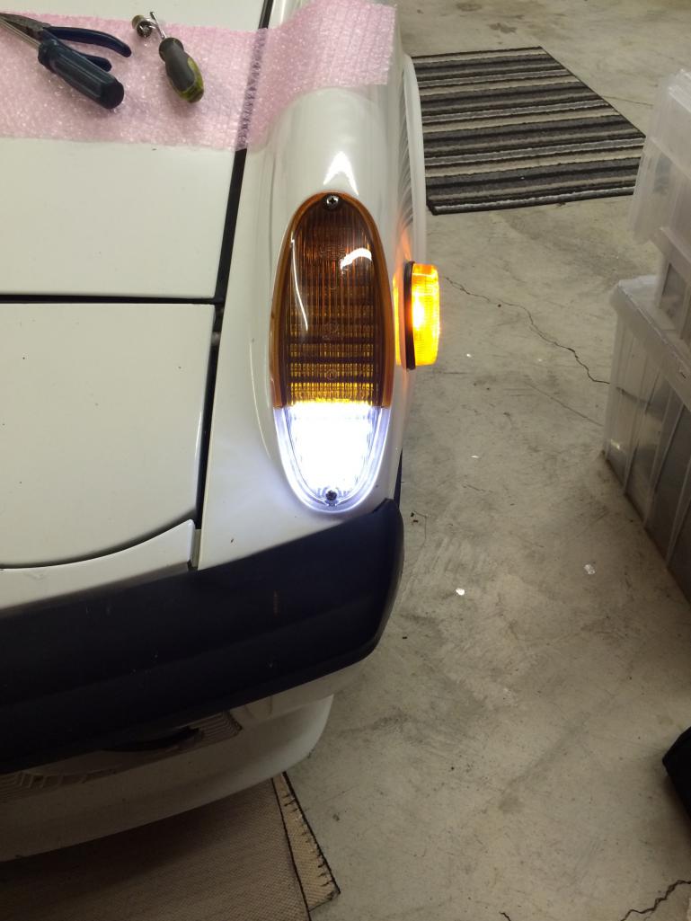
The LED turnsignal: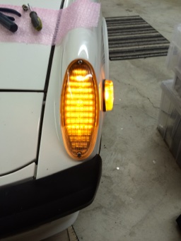
Posted by: siverson Dec 19 2014, 01:05 AM
Looks great!
http://www.reactiongifs.com/r/2012/11/take-my-money.gif
Posted by: euro911 Dec 19 2014, 02:42 AM
Looking good, Jerry
I'm ready for a pair of non-blanking ones when you're ready to start shipping
Question: I currently have a pair of Craig's parking light kits that have a plastic separator between the turn signal and parking light segments in the bucket. Do we need to install some sort of separator to keep illumination from the LEDs from bleeding over?
Posted by: Cairo94507 Dec 19 2014, 08:31 AM
Those look very nice. Can you post a video of the blanking and non blanking operation please.
Posted by: eric9144 Dec 19 2014, 10:14 AM
Still in for US front's and rears, this is exiting!
Posted by: JmuRiz Dec 19 2014, 10:28 AM
GREAT news, I'll start saving my pennies for the front and rear sets.
Posted by: rdauenhauer Dec 19 2014, 01:43 PM


Posted by: Spoke Dec 19 2014, 01:57 PM
Looking good, Jerry
I'm ready for a pair of non-blanking ones when you're ready to start shipping
Question: I currently have a pair of Craig's parking light kits that have a plastic separator between the turn signal and parking light segments in the bucket. Do we need to install some sort of separator to keep illumination from the LEDs from bleeding over?
The separator will not be necessary and may interfere with the PCB. The light output of the LEDs is very directional. For this reason, the LEDs are mounted at an angle on the board to point directly in front of the vehicle.
Posted by: Spoke Dec 19 2014, 05:16 PM
Those look very nice. Can you post a video of the blanking and non blanking operation please.
Here's the blanking version during bench testing. You'll notice the running lights blank immediately when the turnsignal comes on and remains off about 1 second after the last turnsignal blink.
On today's cars the running light comes on immediately after the turnsignal is released. They can do that as everything now is controlled by processors. There is no such signal on the 914 so I wait about a second after each turnsignal blink before turning on.
Sorry I don't have a non-blanking board to show.
https://www.youtube.com/watch?v=RRBFT2LwVhc
Posted by: StratPlayer Dec 19 2014, 06:03 PM
So when do you think you'll be shipping these baby's out?
Posted by: Cairo94507 Dec 19 2014, 06:39 PM
OK, I see how it works now. Thanks for posting that. I can't wait until it is time for me to buy these, front and rear for my car. I hope by then you have an LED side marker setup too.
Posted by: Spoke Dec 19 2014, 10:00 PM
So when do you think you'll be shipping these baby's out?
The boards will arrive just after the new year. I will order parts next week so we will be able to start assembling boards in the 2nd week of Jan.
I did have a clip of the non-blanking front turnsignal. The clip also compares the LED turnsignal on the passenger side to the standard bulb on the driver side.
https://www.youtube.com/watch?v=4y2HTTtBjG8
Posted by: RobW Dec 19 2014, 10:22 PM
I have a couple refurbed signal buckets I can donate to the cause if you need them. Just send me a PM with your address.
Posted by: RickS Dec 20 2014, 10:37 PM
In for a set of the Euro non-blanking (Euro option 2). If I could only run the the white DRLs when the ignition is switched on. Guess I could jump the whites to the ignition, or rig a switch. Or just run with my tail lights on all the time. Hmmm Any way, very well done!
Posted by: chads74 Dec 21 2014, 01:55 PM
I am in for one set of option 2) Euro lens blanking to add to the rear LED lights I already have.
Posted by: GermermanCarGuy Dec 21 2014, 03:22 PM
Still in for Euro-blanking fronts. And, if you're still making rears, I'm still in for a set of those, too.
These are way cool. Any chance you'll add the required flasher and turn this into a complete package deal? If so, I'd be in for a '74 mod with dual dash indicators.
Many thanks in advance. You da man! A true award winning contributor.
Rob
Posted by: Cairo94507 Dec 21 2014, 03:41 PM
I would love to see a package deal that included front turn sigs (I want to go with the blanking euro lens fronts), rear turn signals (USA lenses version), and side marker lights.
I like that the blanking euro-fronts really make the turn signal stand out by turning off the running light lower before the turn signal activates.
What can you do for the side marker light? I wish someone could/would make a side marker replacement lens that was much closer to the body instead of being like 1.5" in depth. Assuming that is a pipe dream, I still want the side markers to be LED and function as running lights and turn signals. A guy can dream.....
Spoke- You have made an outstanding product for our cars that enhances their visibility, improves safety and reduces the electrical draw to power these lights. Your modification also updates the lighting to make the cars look nicer too when the lights function. I fully plan on converting to LED headlights to further that improved electrical safety and reduce the electrical draw to make the headlights bright. Thanks again for all of your time and effort- truly a great contribution to the 914 community.
Posted by: mikesmith Dec 24 2014, 04:15 PM
What can you do for the side marker light? I wish someone could/would make a side marker replacement lens that was much closer to the body instead of being like 1.5" in depth. Assuming that is a pipe dream, I still want the side markers to be LED and function as running lights and turn signals. A guy can dream.....
I used two of these - you can see them in the shots that Spoke posted:
http://www.dx.com/p/g4-3w-110lm-led-yellow-light-car-reading-lamp-dc-8-30v-156534
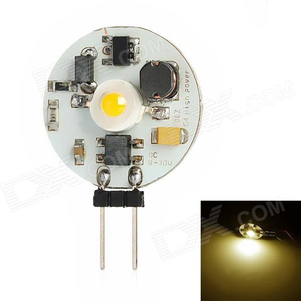
Remove the pins, solder some small wires from the pads to the contacts, then a little RTV to hold the module in place.
If you want to make the markers flash with the turn signals, you can use the Modifry modules:
http://www.modifry.com/index.php?route=product/product&path=18_66&product_id=75
I would not mount these "under the fender" on a 914; the screw terminals really need to be protected from moisture and dirt. Inside the front bucket is probably a good location if you don't mind fiddling the wiring on the back of the bucket (you need a get a wire out for the sidemarker).
You could also use something like these:
http://www.ebay.com/itm/2-x-Amber-LED-Eagle-Eye-Bulbs-Backup-LED-Daytime-Light-license-plate-light-3W-/261533408711?pt=Motors_Car_Truck_Parts_Accessories&hash=item3ce49b1dc7&vxp=mtr
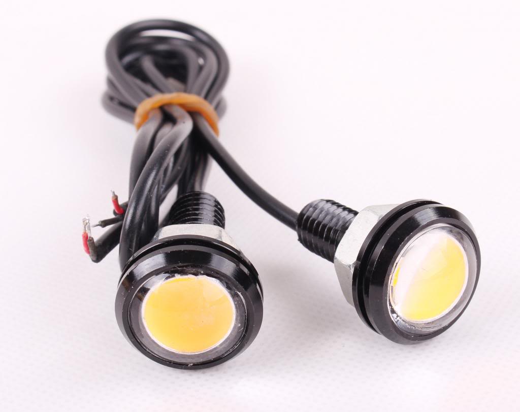
after removing the contacts from the stock housing.
Posted by: euro911 Dec 24 2014, 07:37 PM
The top one looks like a fried egg 
I like the second choice ... I may just order some
Thanks for posting
Posted by: mikesmith Dec 24 2014, 10:15 PM
The top one looks like a fried egg
I like the second choice ... I may just order some
Please post pictures if you do; they look like they could be a very simple drop-in to the existing housing.
Posted by: Spoke Jan 7 2015, 12:35 PM
Ordering parts now. Should have everything by next week to start building.
Let the fun begin.
Attached thumbnail(s)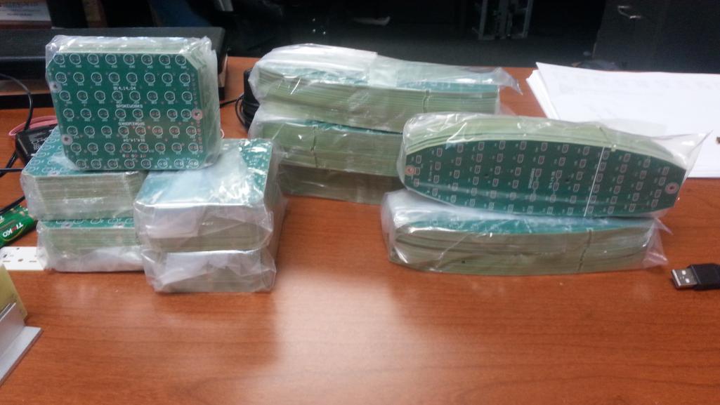
Posted by: chads74 Jan 7 2015, 01:23 PM
I am excited!
Posted by: eric9144 Jan 7 2015, 02:06 PM
Posted by: GermermanCarGuy Jan 7 2015, 03:13 PM
The top one looks like a fried egg
I like the second choice ... I may just order some
Me too. Not quite ready for the install just yet; too much rust to take care of first.
It's the little things like this that keeps me going. Great hindsight. Many thanks in advance.
Posted by: siverson Jan 7 2015, 04:28 PM
Great!
Posted by: ConeDodger Jan 7 2015, 04:40 PM
please...
Nice
Wouldn't it be more like this though, Rob ?
E
U
R
O
:poke
Welcome to the asshat club Mark!
Depends on which side of the car your standing on.
... and I'm in for a pair of EURO units of course
Posted by: Mueller Jan 7 2015, 04:58 PM
Just finished reading this entire thread, great product!
Too broke right to commit, hopefully in 6 months or so you'll be doing another batch for both ends of the car!
Posted by: Spoke Jan 14 2015, 08:46 PM
Measured the output of the US front LED board compared with the standard bulb. The meter reads out in LUX.
Here's the setup used. The power to the LED board and bulb is 14V. Both were measured with running lights and turnsignal.
With running lights on, the bulb burned 8W (0.6A) while the LED burned 1W (0.07A).
With turnsignal on, the bulb burned 26W (1.9A) while the LED burned 5.5W (0.4A)
I took light measurements at eye level being 0, 10, 20, 30, and 45 degrees off of the front of the bucket; each measurement 4 feet away from the bucket.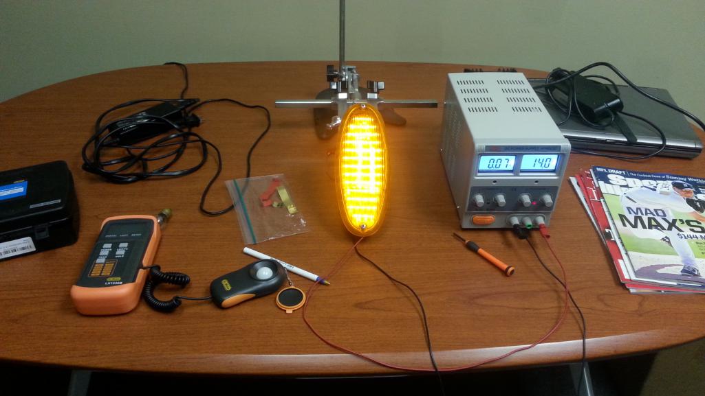
These LEDs are 23 degree devices. All boards made will have 30 degree LEDs to further widen the intensity in front of the car.
Here's a comparison of the running lights. The LEDs are a bit over 8x more intense in front of the vehicle and remain brighter even 45 degrees off center.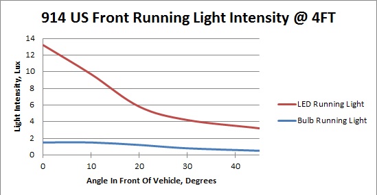
The LED turnsignal intensity is over 6x as intense as the bulb at 0 degrees. The LEDs have a nice wide angular intensity profile which is good as the turnsignals in the front will be bright for cars off the road waiting to enter in front of a 914 or when changing lanes. 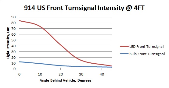
This graph is an attempt to show the light pattern in front of the car. The lines indicate where the LEDs are 6x, 3x, and 1x the intensity of the bulb.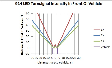
Posted by: Cairo94507 Jan 15 2015, 07:22 AM
That's exactly the kind of brightness these little cars need to be seen. Excellent work. I can't wait to buy a complete set for my car. Scotty is working away and hopefully soon I will be able to buy a set.
Posted by: cary Jan 15 2015, 07:24 AM
Switching to the EP36 flasher. After driving the car a bit. The flasher indicator only flashes left or right once. Then goes to a slow dim blip on both. Rear LEDs seem to still run fine.
I assume the ground wire arrangement will manifest itself when I get there. The special lug will go on the incoming wire harness for the flasher socket?
Posted by: Spoke Jan 15 2015, 11:42 AM
Switching to the EP36 flasher. After driving the car a bit. The flasher indicator only flashes left or right once. Then goes to a slow dim blip on both. Rear LEDs seem to still run fine.
I assume the ground wire arrangement will manifest itself when I get there. The special lug will go on the incoming wire harness for the flasher socket?
What did you do with the wire that was on the K/C lug on the original flasher? This is the one that goes to the common connection of the indicators. This is the one that must be grounded with the EP36.
PM me if you want me to send you one of the piggyback adapters for this wire. Without grounding the wire from K/C, the indicators will not work properly.
Posted by: euro911 Jan 15 2015, 03:08 PM
Thanks for posting the results, Jerry.
Now, stop typing and get back to soldering 
Posted by: cary Jan 16 2015, 08:44 PM
Trying to figure out where you want us to attach the common to the ground.
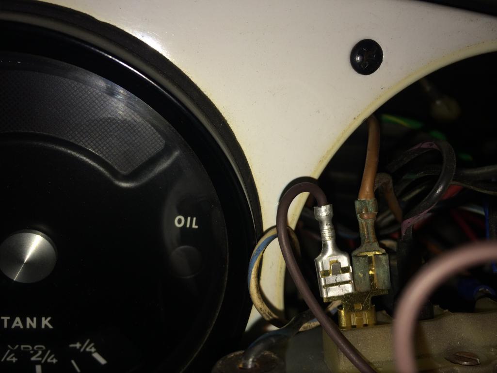
1973.
EP36 with piggyback terminal.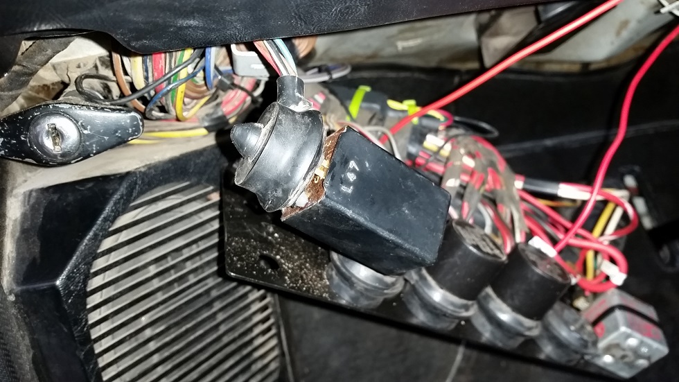
Here's the flasher relay arrangement.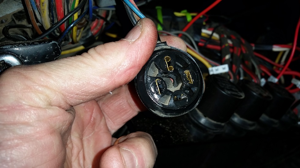
Here's socket for the relay. How do I get to the ground wire with the
relay seated in the socket?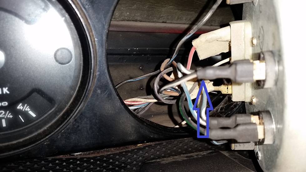
Here's the common wire on the back of the tach.
Posted by: Spoke Jan 17 2015, 12:13 AM
This is the first time I've seen the connection of the flasher relay. The piggyback connectors will not work unless the connector is cut apart to reveal the individual wires.
So what would be better here is one of those crimp-on jumpers to connect the 2 wires together.
Posted by: Spoke Jan 17 2015, 12:17 AM
I think this is the crimp part to use. Your local FLAPS should also have it.
http://www.radioshack.com/wire-tap-in-squeeze-connectors-10-pack/6403052.html#start=11
Determine the 31 wire (ground; should be brown) and the K wire and crimp them together.
Attached image(s)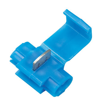
Posted by: cary Jan 17 2015, 01:01 AM
Ok that makes me feel better. I was beginning to feel like a dumb ass.
On the 73 schematic the ground is brown and the common is BLUE/white.
Posted by: Spoke Jan 17 2015, 10:13 AM
Ok that makes me feel better. I was beginning to feel like a dumb ass.
On the 73 schematic the ground is brown and the common is black/white.
That was my fault. I had never seen or replaced the flasher and thought the piggyback spade would work but not with the single connector for all 4 wires. Thanks for the pics.
I will include one of the crimp connectors with front or rear LED turnsignal boards.
Cheers
Posted by: Spoke Jan 17 2015, 10:21 AM
I think this is the crimp part to use. Your local FLAPS should also have it.
http://www.radioshack.com/wire-tap-in-squeeze-connectors-10-pack/6403052.html#start=11
Determine the 31 wire (ground; should be brown) and the K wire and crimp them together.
Upon further review, I'm not sure this crimp connector will work because it takes one existing wire and may require the second wire to be cut and inserted into the other slot. I'd like to see a solution where neither wire is cut.
This article shows better pics of some of the wire-tap connectors on the market.
http://tech.bareasschoppers.com/resources/the-problem-with-wire-tap-connectors/
Posted by: Spoke Jan 17 2015, 10:27 AM
mikesmith solved this dash indicator issue by making a pigtail to ground both the dash indicators to the existing ground lug on the tach.
Attached thumbnail(s)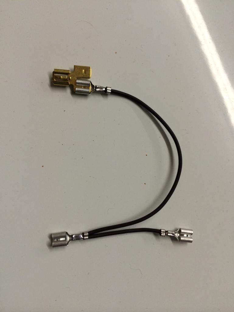
Posted by: euro911 Jan 17 2015, 12:39 PM
Upon further review, I'm not sure this crimp connector will work because it takes one existing wire and may require the second wire to be cut and inserted into the other slot. I'd like to see a solution where neither wire is cut.
This article shows better pics of some of the wire-tap connectors on the market.
http://tech.bareasschoppers.com/resources/the-problem-with-wire-tap-connectors/
Posted by: cary Jan 17 2015, 01:30 PM
Does the indicator common just need to go ground.
Or does it need some sort of top secret ground
signal from the flasher ground.
Posted by: Spoke Jan 17 2015, 01:45 PM
Does the indicator common just need to go ground.
Or does it need some sort of top secret ground
signal from the flasher ground.
The dash indicator common just goes to ground; any ground. It behaves then like any of the front or rear turnsignal lamps.
Posted by: cary Jan 23 2015, 12:20 AM
Pulled the tach out.
Looks like I mis-read the wiring diagram. The common is blue/white.
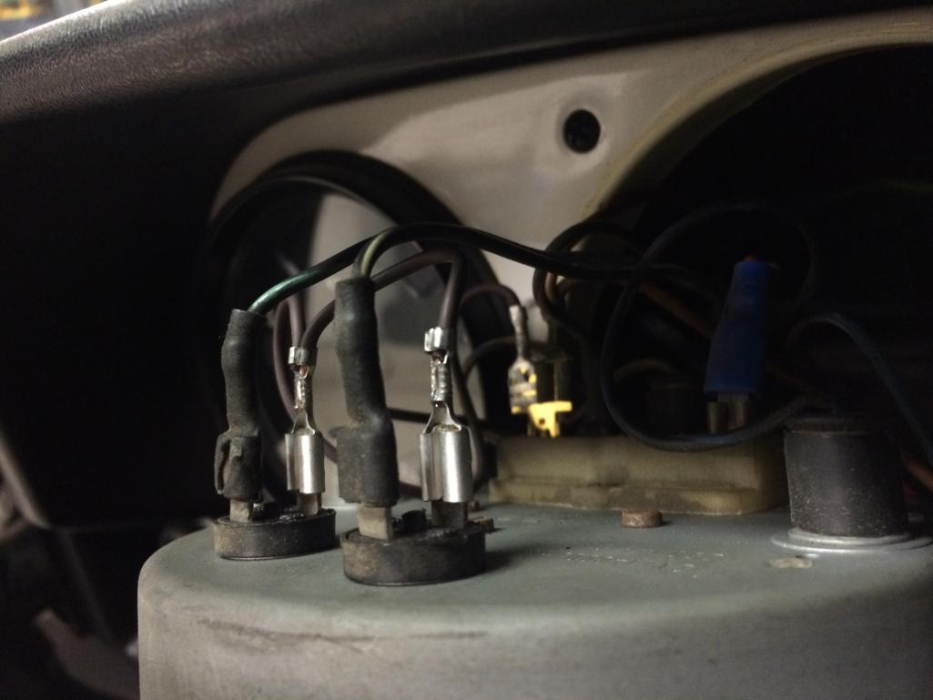
So looking at mikesmith's work. I'll remove the blue/white wires and zip tie them out of the way. Then replace them with the 3 wire jumper.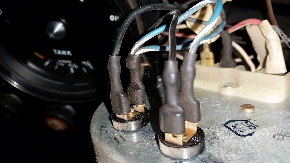
Posted by: mikesmith Jan 23 2015, 02:26 AM
Pulled the tach out.
Looks like I mis-read the wiring diagram. The common is blue/white.
So looking at mikesmith's work. I'll remove the blue/white wires and zip tie them out of the way. Then replace them with the 3 wire jumper.
That's what I did. Make sure you insulate the ends of the blue/white wires so that they can't short to ground.
Sorry about the bad lighting in the shot I sent to Spoke.
Posted by: cary Jan 23 2015, 07:13 AM
I think I'll pull them back to the flasher socket and zip tie them to the harness below it.
That way they're out of the way and obvious as to what they are.
Thanks for the engineering.
Posted by: cary Jan 24 2015, 09:32 PM
Got home early and worked on the indicator grounds.
Works like a champ. Couldn't pull the common back the socket. Harness taped up in a couple different spots. Thanks from all the help.
Patiently waiting for the front LED lights.
I also installed my new Euro front lenses from Camp914.
https://www.youtube.com/watch?v=NlUfLRn8eA0
Powered by Invision Power Board (http://www.invisionboard.com)
© Invision Power Services (http://www.invisionpower.com)