Printable Version of Topic
Click here to view this topic in its original format
914World.com _ 914World Garage _ Electrical Question #15 Need Help Please
Posted by: 76-914 Apr 6 2014, 06:33 PM
I'm going to have several electrical questions. 1st, Is pin #8, on the 14 pin plug at the relay board, the only switched 12v+ source in the engine compartment? TIA, Kent
Posted by: Mike Bellis Apr 6 2014, 07:38 PM

I'm going to have several electrical questions. 1st, Is pin #8, on the 14 pin plug at the relay board, the only switched 12v+ source in the engine compartment? TIA, Kent
Yes, Can be used as a coil power wire when switching to carbs as well.
Black wire
Posted by: Jeff Bowlsby Apr 6 2014, 09:48 PM
Careful, not all model years are the same. Check the schematic for your car.
Posted by: Tom Apr 7 2014, 03:04 AM
I checked all of the schematics I can find and all have the black wires at pin #8 as switched hot from the key switch. To be safe, put a meter on it and verify that it is hot when switched on at the key switch. Battery isn't necessary to check that it would be hot. Just use one meter lead on the 4 red wires, the other on pin #8. With the key to on, you should have continuity. Key to off, open. What year car?
Tom
Posted by: 76-914 Apr 7 2014, 06:29 AM
I checked all of the schematics I can find and all have the black wires at pin #8 as switched hot from the key switch. To be safe, put a meter on it and verify that it is hot when switched on at the key switch. Battery isn't necessary to check that it would be hot. Just use one meter lead on the 4 red wires, the other on pin #8. With the key to on, you should have continuity. Key to off, open. What year car?
Tom
It's my '73 Tom, which was a 1.7 originally with your fused adapter in place. My plan is to use this wire to activate a new power relay. Glad you and Mike are here to oversee this part.
Posted by: 76-914 Apr 7 2014, 06:37 AM
Question #2 - Do I need to use a N/C relay off the starter circuit to kill the radiator fans when cranking/starting. I'm hoping the answer is no but thought I'd better ask now. TIA, Kent
Posted by: Tom Apr 7 2014, 11:37 AM
Kent,
Don't know why as they don't draw that much. Is the Subie ECU controlling them? If so, that feature may already be in place inside the ECU because Subaru found it to be an issue, but I don't know for sure. If you found it to be a problem, it wouldn't be that hard to remedy. A 30 amp relay wired for the starter circuit to open the fan circuit. Basically the fan power to 30, ground to 85, fan energized to 87A (NC contact), and starter power from the key switch to 86. Whenever the starter circuit is energized, the relay opens and fans have no power. Stop starting, power to fans is back.
I think this would mostly depend on how much current the fans draw if the engine is hot and both are running to cool it. Say you drive 15 miles to the store and are inside 5 min and come back out. Would the fans still be running? This would also be determined on the battery condition and CCA. A battery with 500CCA will give 30 seconds of cranking at a big amperage without falling below a certain percentage of battery voltage. So if the starter is drawing 120 amps and fans 30 amps, that should not be a problem unless the battery is on the way out.
Tom
EDIT: Cold cranking amperes (CCA) is the amount of current a battery can provide at 0 °F (−18 °C). The rating is defined as the current a lead-acid battery at that temperature can deliver for 30 seconds and maintain at least 1.2 volts per cell (7.2 volts for a 12-volt battery). It is a more demanding test than those at higher temperatures. This is the most widely used cranking measurement for comparison purposes.
Posted by: 76-914 Apr 7 2014, 02:33 PM
Damn,  I didn't consider that the ECU would have that covered.
Posted by: 76-914 Apr 28 2014, 10:28 AM
#3 - What is the difference between a 5AG 30A fuse vs. a AGU 30A fuse. Are they interchangeable? TIA, Kent
Posted by: Tom Apr 28 2014, 12:18 PM
Kent,
The designations before the Amperage is for applications such as voltage, current flash over, and several other factors. Also designates glass enclosed or ceramic enclosed, what type of coating on the ends, etc. You would need to look each one up to determine which fuses these are meant for. This is why I stayed with ATC for my fuse blocks. It prevents someone from putting a clear glass fuse that "looks" the same in a circuit and the fuse is not rated at what the person thought. I don't know how many times I have worked on electronic equipment that some one replaced the fuse with one that looked identical until you read the inscription on the fuse that indicated it was for a 28 volt use and it was placed in a 125 volt circuit. Not good, as the fuse was no longer protecting the circuit as the proper fuse would. If you are interested in expanding your knowledge, look up "FUSEOLOGY". Very enlightening.
Tom
Edit: some research discovered. AG = auto glass
AGU = Fast-Acting Glass Tube Midget Fuses
Posted by: 76-914 Apr 28 2014, 06:56 PM
Had to read thru some heavy stuff for my pea brain but I was able to learn this much. The 5 denotes it's physical size. In my case 13/32" x 1.5". That car fuses are slow blow to handle the large surges and are usually the 32V group. Now I need to take a nap. 
Posted by: Dtjaden Apr 29 2014, 08:39 AM
The easiest location for switched 12v on the relay board is pin 1 on the 4 pin spade lug connector on the relay board. The location on the board is toward the rear on the drivers side.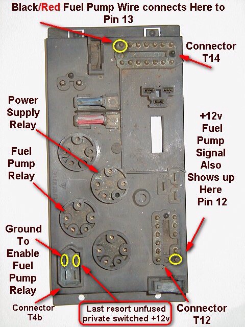
Posted by: 76-914 Apr 29 2014, 08:59 AM
That could be useful info for someone that is using the relay board. I 86'd mine during the Suby conversion, however. 
Posted by: 76-914 May 2 2014, 08:33 PM
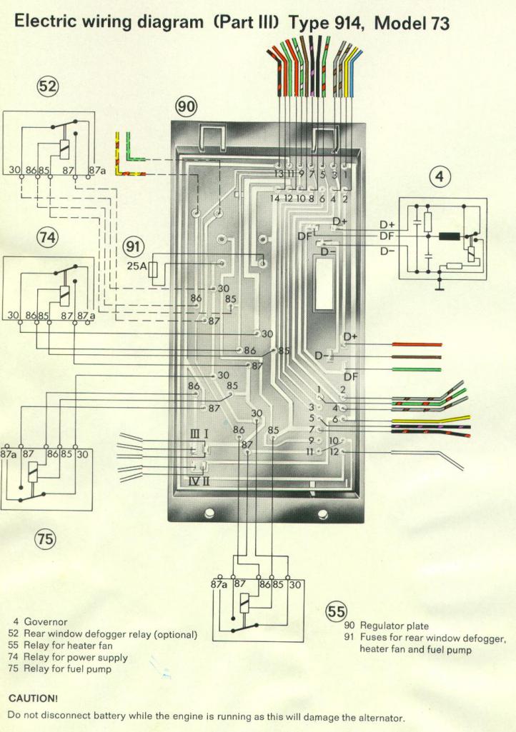
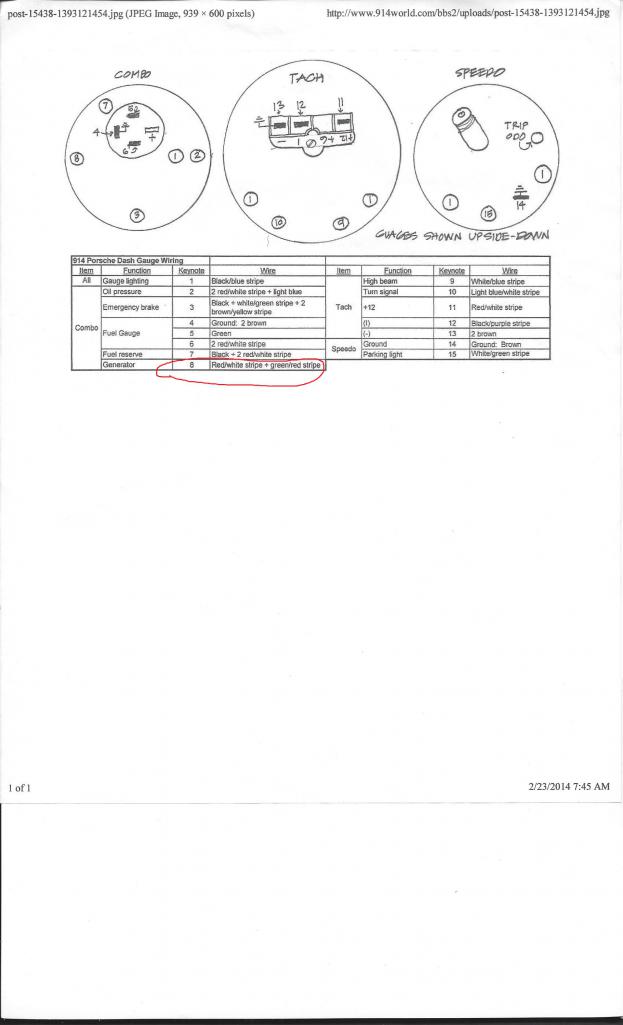
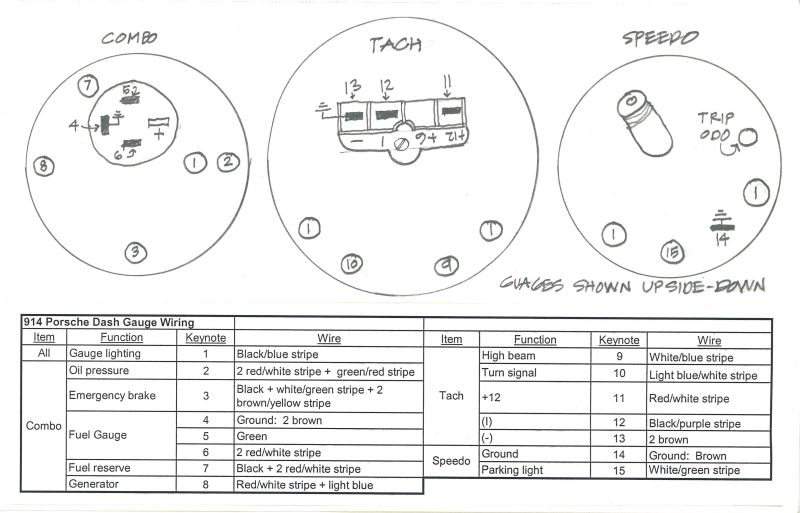
#4- I need to tie in my alt light with the suby engine. I have a single wire from the Suby to connect to the GEN light but don't know where to tie it in. I looked at Jeff B's info (thx Jeff) and found which bulb it is and there are 2 wires. A R/W and a G/R wire. The R/W goes to fuse 9 and to other gage bulbs so I can rule that one out. Maybe a switched + for bulb power? That leaves me with the G/R which goes to the relay board #5 on the 14 pin plug then out the 12 pin #1 to the OIL pressure switch. I don't understand this.
Posted by: Dave_Darling May 2 2014, 10:07 PM
Green/red would be the oil pressure light, not the alternator light.
That one has a blue wire and a red/white wire. The red/white supplies +12V, while the blue wire connects to the D+ wire coming from the alternator to the voltage regulator.
--DD
Posted by: Mike Bellis May 2 2014, 11:40 PM
The alternator lamp work with 2 positive leads. One is switched from the key, through a fuse and to the lamp. The other is the D+ from the alternator. When the alternator spins and creates voltage (2nd positive) the dash lamp turns off. When the engine is not running, the D+ turns "less positive" and the lamp lights up.
Posted by: Tom May 3 2014, 01:32 AM
That red/white that goes to fuse #9 on the fused side is the correct wire for one side of the alt bulb. The other side is a blue wire that goes to the alternator at D+.
Tom
Posted by: 76-914 May 3 2014, 10:10 AM
Odd. I have one sch showing GR yet today I find the one you mention w/ Blue on another print out in Jeff material. Are there two and I have the wrong one?? Many TY's for the assistance, guy's. 
Posted by: Jeff Bowlsby May 3 2014, 11:05 AM
Odd. I have one sch showing GR yet today I find the one you mention w/ Blue on another print out in Jeff material. Are there two and I have the wrong one?? Many TY's for the assistance, guy's.
That diagram was superseded., it was not correct. I try to keep the website materials correct, and I replaced that former diagram on the website in May 2013 with this corrected one. Keep in mind that this diagram is only for the 1974 model years, other years are different:
Attached image(s)
Posted by: 76-914 Jun 4 2014, 01:54 PM
#5 - If you own a 914 you know the importance of a good ground. As I went through the Subaru harness I counted over 20 grounding points so Suby has a good idea, also.
My question is this. Are there rules that govern grounds? If so, can a layman understand them? Can a ground junction become ineffective if too many grounds converge at one point? Does a ground need to be sized? Should it be the same gauge as the positive circuit it completes? If adding ground points does the material type matter? e.g. brass, steel. As always, TIA, Kent
Posted by: stugray Jun 4 2014, 02:04 PM
Cut & paste from my response to another forum where someone was troubleshooting an AFR gauge, but most of it still applies:
""Grounding" is a science all to itself.
Cars typically use chassis as a "Ground reference" and a "Current return path".
For sensitive electronics (O2 sensors) they need a proper "ground reference" that tells the circuitry what voltage is "Zero volts" as far as the system is concerned.
When you use car chassis as this ground reference, then it is not always at "zero volts" with respect to the rest of the car because the voltage of any particular point in the chassis is dependent on how much current is flowing through chassis and where the current is flowing.
So if you "reference" the O2 sensor to car chassis close to the sensor, then the ground can move up or down depending on if (for example) the radiator fans are on or off. This is because current flowing through the chassis causes voltage drops in this reference.
For the more sensitive sensors, you should run a dedicated "ground reference" from the sensor to the unit reading the sensor.
If you use chassis for this, then the "zero volts" reference is not always at "true zero".
If anyone cares and is confused by this, I could make a diagram..... "
"This is where "grounding" gets a little confusing.
The meter/O2 gauge needs +12V power so it needs a ground (called a 'return' in my business because it intentionally carries the return current to the power source).
This would go to the battery negative.
The part of the system performing the voltage measurements within the O2 sensor needs a ground 'reference'.
This ground does not carry any significant current so it does not experience voltage drop during operation.
That ground 'reference' should go from the Measuring unit (gauge or ECU) all the way to the sensor.
Some older sensors (VDO oil pressure for instance) did not provide a dedicated ground to wire to and depended on the car chassis to provide the path.
Newer sensors typically have dedicated reference 'grounds'.
Theoretically, you could hook the reference wire to car chassis at the sensor end and at the gauge end and in most cases it will work.
Is it accurate? Each installation could be different and give different results."
So to answer your questions: "Pickles" :-)
In all seriousness: If the "Ground" actually carries current, then the wire needs to be the same gauge as the "positive" wire or larger.
In a perfect world we would connect all "grounds" to one point, know as the "Single point ground" but we dont usually have that luxury, so the entire car chassis is the "SPG" (we call it 'SPUG' at work).
Material does not usually matter except for long term corrosion problems or highly sensitive signals that could be upset by galvanic voltages being induced.
Did I completely confuse you yet?
Posted by: 76-914 Jun 4 2014, 02:39 PM
Not completely confused, yet. You state that the ground should be the same size "if" it is carrying the same amount of current. How is this determined? Let's say I have a circuit that requires a 12 gage wire. Does the ground carry that same force or has that amount now dropped because it has passed through the device it supplies? Does a lamp circuit that may require 5 amps require a ground the same size or can it be smaller because the lamp has consumed most of the flow?
These reference grounds that you speak of; are they best routed back to the BAT? TOM suggested (and I did this) to loop or connect all my grounds in the engine compartment via a large ga wire. And yes, my 02 sensors do have a separate ground wire. That's a reference ground, right? Thx Kent
Posted by: Dave_Darling Jun 4 2014, 03:30 PM
The short answer, which is close enough for our purposes:
- Always make the ground wire at least as big as the power wire. If it requires a 12ga wire to power it, it needs a 12ga wire for the ground wire.
Note that the body of the car is about a negative fifteen-hundred gauge wire for most of our purposes... 
--DD
Posted by: jrrhdmust Jun 4 2014, 03:33 PM
Thank you, thank you, thank you!! I needed that!
Posted by: IGTARD Jun 4 2014, 04:34 PM
 Jumping in. Iigniting would die. 914 fixed that. Battery dead. Charger started car. Cigarette plug dead. 914 fixed that. Car caught on fire (dash wiring). 914 fixed that. Still a draw somewhere on battery. 914 installed a guillotine kill switch. Found (?) draw right headlinght stays illuminated after being turned off and dropping.
  Help Shalom, IGTARD
Posted by: Tom Jun 4 2014, 05:54 PM
Kent,
Answer for your question about wire size for ground. The current through the complete circuit is the same at all points of the circuit. So 12 Ga. supply into equipment, 12 Ga. ground out.
Tom 
Posted by: 76-914 Jun 5 2014, 09:07 AM
Kent,
Answer for your question about wire size for ground. The current through the complete circuit is the same at all points of the circuit. So 12 Ga. supply into equipment, 12 Ga. ground out.
Tom
Thx Tom, that's what my gut was telling me but this is one of those areas where I prefer professional knowledge over my common sense.
**NOTE** FWIW, I believe I ran into one of those "reference ground" issues, yesterday. There is a small harness that goes from my fuel pump controller to the pump. One of those wires is a ground. If left open the pump runs continuously but when connected the pump senses pressure.
Posted by: 76-914 Sep 18 2014, 07:26 PM
OK, another stupid electrical question. I have not been able to get a detectable ground signal from my ECU to control my radiator fans. I decided it would be just as easy to install 2 thermal senders with different set points to control the Hi n Low fan features. I noticed that many people slammed these senders but upon further reading I found that many were not using relays and put too much of a load on them. That's not a problem for me as I am using relays. But this got me to thinking. If I use the single pole style, which requires the metal block for a ground, will I end up dumping a lot of stray current into my coolant? TIA, Kent
Posted by: Mike Bellis Sep 18 2014, 09:30 PM
Your steel chassis should still be a better ground conductor than radiator coolant. If your engine and chassis are bonded, the path of least resistance will not be the coolant. Even if there were stray current, it would possibly be from the spark plugs that every engine has. I son't see any risk unless you have dissimilar metals contacting each other.
Posted by: Spoke Sep 19 2014, 05:20 AM
If I use the single pole style, which requires the metal block for a ground, will I end up dumping a lot of stray current into my coolant? TIA, Kent
Where are you mounting these switches? I've seen them in the radiator before. If you are using a grounding type switch on the radiator, you should ground the radiator with a ground strap to provide a dedicated ground.
If the switch is on the engine block, the block should have a ground either on the block itself or on the transmission.
Posted by: 76-914 Sep 19 2014, 08:44 AM
I have one chassis to tranny ground, 2 chassis to engine block grounds, 2 chassis to intake manifold grounds, 10ga ground on the fans and I've chained the engine compartment chassis ground points back to the battery itself. Is that proper or did I overlook something? TIA.
Posted by: 76-914 Nov 7 2014, 08:30 PM
#7 - I need to connect my stock '73 back up lights and will use a relay to power the lights because the old Porsche harness was 86'd . My question is this; should I use the switch on the Suby trans to connect the circuit on the -neg or +pos side? My thought is why run 12v in that area if a ground does the trick and wouldn't be a problem if road elements were to take out a wire. Thoughts? Advise?
Posted by: Spoke Nov 7 2014, 09:35 PM
Use the negative side to switch the backup lights on and off.
It is usually safer to run 12V to the coil of the relay, then the negative of the coil to the switch on the trans.
One way to look at it is if the contacts of the switch were to be accidentally grounded, you won't blow a fuse; the light will just turn on. If it were 12V, then a fuse would blow.
Posted by: stugray Nov 7 2014, 11:52 PM
For my stock trans w/ custom harness, I just took a wire with inline fuse-holder from the starter to the backup switch, then from the switch to the rev lights.
That would be bad with a stock harness if you left it in reverse as that terminal on the starter is hot all the time.
Posted by: 76-914 Nov 8 2014, 06:41 PM
Use the negative side to switch the backup lights on and off.
It is usually safer to run 12V to the coil of the relay, then the negative of the coil to the switch on the trans.
One way to look at it is if the contacts of the switch were to be accidentally grounded, you won't blow a fuse; the light will just turn on. If it were 12V, then a fuse would blow.
That was exactly my thinking as well. Right down to the backup short circuit displaying a CEL thru the back up lights.
 When cannibalizing that Subaru I noticed neg switching was the way.
 For my stock trans w/ custom harness, I just took a wire with inline fuse-holder from the starter to the backup switch, then from the switch to the rev lights.
That would be bad with a stock harness if you left it in reverse as that terminal on the starter is hot all the time.
True. And a fuse holder would be prone to corrosion in that area as well.
Posted by: 76-914 Nov 22 2014, 02:36 PM
Will one of our electrical wizards help me out with this please. I want to employee the neutral switch on my Suby transmission. Oddly enough the switch is OPEN in neutral and CLOSED in gear. Life would be simpler if vice verse.  My existing system is as shown in the first pic. BTW, the neutral switch is not going to ground at present or in this first pic.
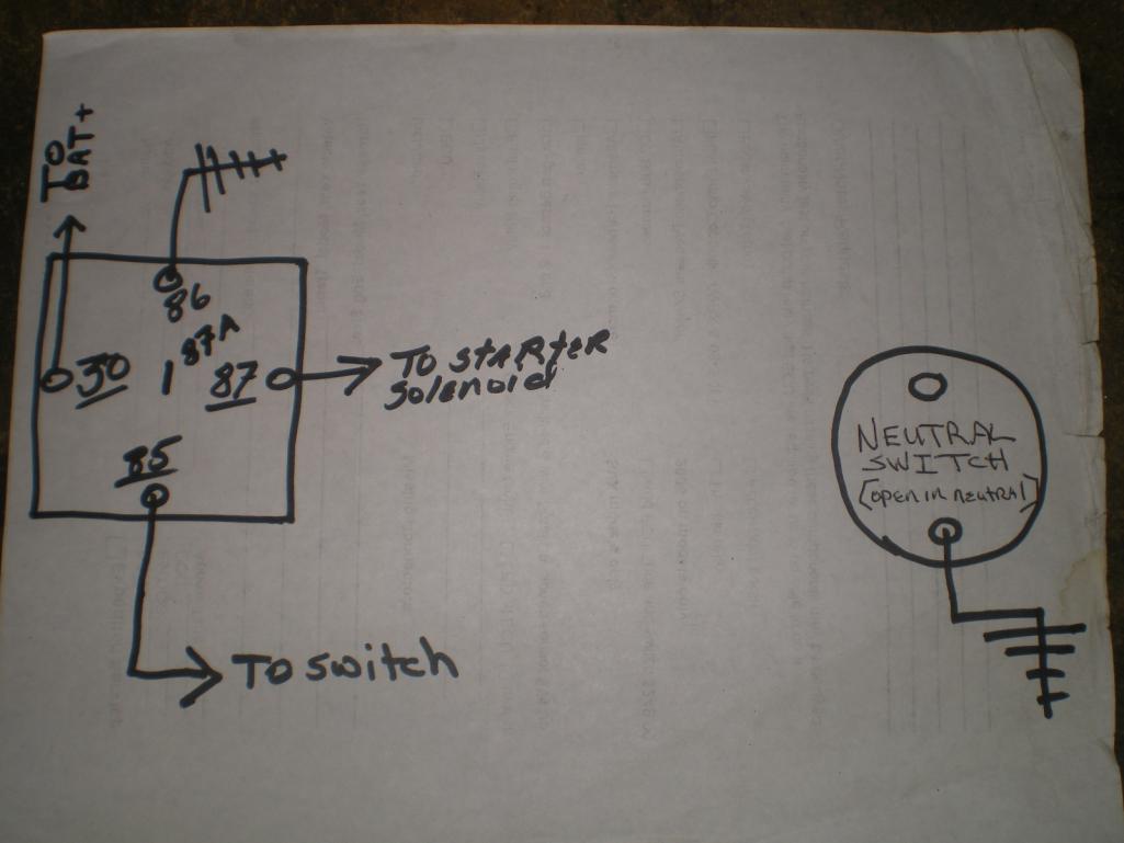
After scratching my watch and winding my ass for the past hour this 2nd pic is my solution. Question: Did I miss something obvious and could I achieve the same result by re-wiring the existing 5 pole relay? And will this work? TIA, kent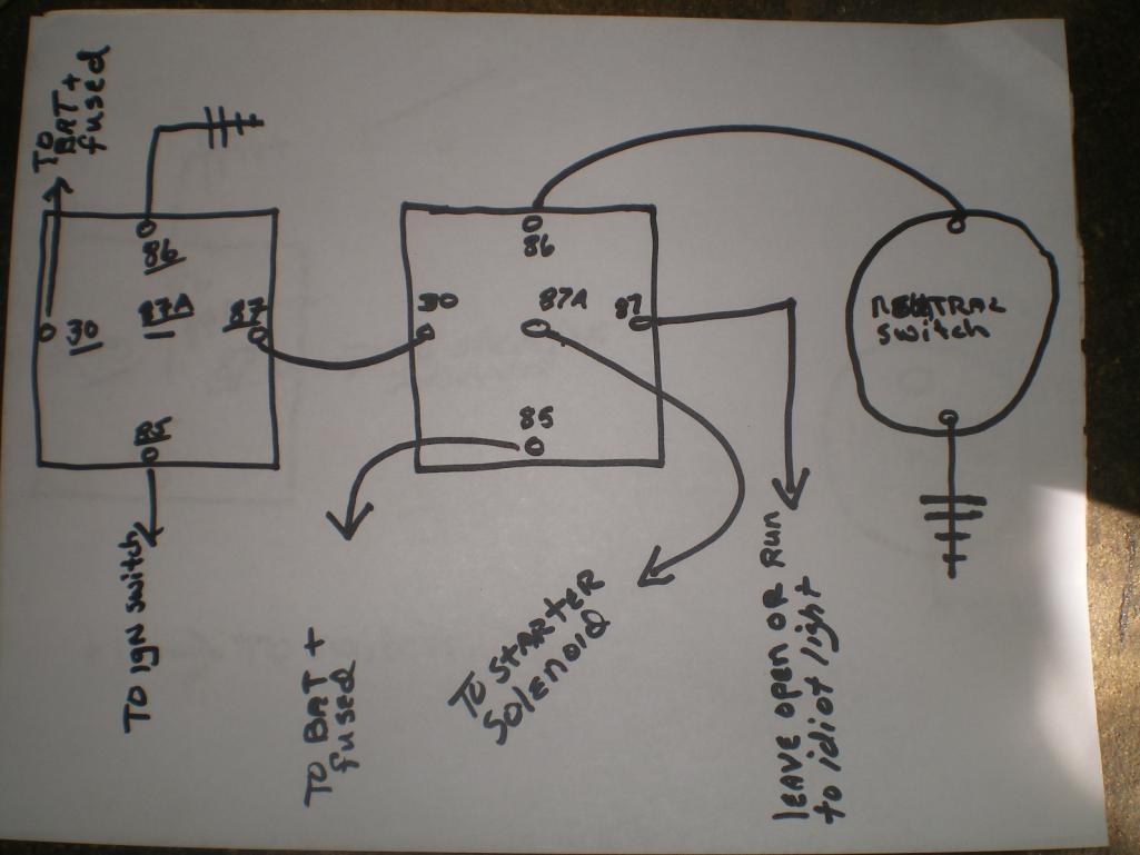
Posted by: Tom Nov 22 2014, 03:54 PM
Kent,
What are you using the neutral switch for? Starter solenoid? Safety switch so it won't start in gear ??? If that is the case, then your second schematic is correct!! You learning lectricity!
Tom
Posted by: 76-914 Nov 22 2014, 07:39 PM
Kent,
What are you using the neutral switch for? Starter solenoid? Safety switch so it won't start in gear ??? If that is the case, then your second schematic is correct!! You learning lectricity!
Tom
Exactly Tom. I almost took out my bench one day.
Thanks for the confirmation. I'm not so sure about that learning part though. To tell the truth I learned a lot from that "2 speed 3 relay" fan set up that Bob posted. After that I began to see how you could use those switches in different ways. Now, how quickly I figure out the correct path; that is another matter.
Posted by: Spoke Nov 23 2014, 10:57 AM
Nice circuit.
I redrew it to better follow the flow.
Attached image(s)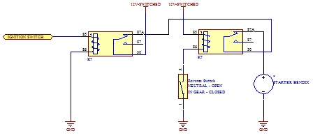
Posted by: 76-914 Nov 23 2014, 08:44 PM
Well guess what. The Suby Computer didn't like it one bit. It idled up n down between 500-1200rpm every 1.5-2 seconds. Disconnected that relay from the circuit and it idles normal again. I'll have to think about this one. It's very easy to reconnect that relay later if needed.
FWIW, it worked as intended as far as not starting in gear.
EDIT: I just had a thought. I'm pretty sure it was in reverse when the idle began to oscillate wildly. I shut it down immediately and removed the relay before confirming that it would do the same thing in forward or neutral! What if my backup lights let some voltage back thru the backup switch, which shares the same ground post and is located within 3" of the neutral switch.
Posted by: Mike Bellis Nov 24 2014, 08:48 AM
I have found on my Audi conversion the ECU likes to see an exact impedance from a relay. As an example, the stock main relay is 30 Ohms. A Bosch relay is 15 Ohms. I have to run 2 relays in series to match the impedance (30 Ohms). If not the ECU will see a fault. If your neutral switch is connected to the ECU in any way, the same could be happening. It would be unusual for this switch to directly connect to the ECU but it may be the case.
Using an Ohm meter you should verify the switch is completely isolated from any other circuit. If it is isolated, the effect you describe should not happen. So you may have a wiring fault.
Posted by: Spoke Nov 24 2014, 09:55 AM
Well guess what. The Suby Computer didn't like it one bit. It idled up n down between 500-1200rpm every 1.5-2 seconds. Disconnected that relay from the circuit and it idles normal again. I'll have to think about this one. It's very easy to reconnect that relay later if needed.
FWIW, it worked as intended as far as not starting in gear.
EDIT: I just had a thought. I'm pretty sure it was in reverse when the idle began to oscillate wildly. I shut it down immediately and removed the relay before confirming that it would do the same thing in forward or neutral! What if my backup lights let some voltage back thru the backup switch, which shares the same ground post and is located within 3" of the neutral switch.
I'm confused on why the ECU would sense what you've done with the neutral switch. Are there connections from the neutral switch to the ECU that you didn't show in your diagrams?
If there are ECU connections, measure the voltage across the switch in neutral or in gear. You would be able to use a pre-biased transistor to interface the switch.
Posted by: 76-914 Nov 24 2014, 09:02 PM
Spoke, no direct connections between the ECU and relays. Both the relays share the same switched ign source. The starter relay is grounded on a dedicated ss ground stud at the firewall. The neutral switch is grounded at the stock tranny ground stud along with the tranny grd and back up switch grd. I remember hearing that ECU's can suffer from ground problems and thought maybe a stray current to a nearby ground might influence the ECU. I guess not, huh? I freaked as ECU's are Voodoo to me so I wanted to disconnect the relay quickly to see if it would return to normal. It did so I will go back and explore further as Mike suggested.
Mike, your probably onto something re: a wiring fault. I re-used a "4 fuse" block that has spade fittings on the bottom.  I'm going to 86 it and install a 6 fuse block with the screw terminals on the side. There are 3 circuits on the existing 4 fuse block. Backup lights/bat fused to ECU/switched fused to ECU. Sounds like I'm in the right neighborhood to begin my search. I appreciate all of you guys holding my hand while I tackle this.
Posted by: Tom Nov 25 2014, 03:22 AM
Kent,
If the gear selector is in neutral, with neither relay energized, what happens? You said it hunted up and down when the gear was in reverse. next step I would do is put everything back as before when it hunted and put the gear in neutral. If it hunts, pull the power ( fuse ) for the relays and see what happens then. Oh, are any ECU sensor wires running near the relay?
Tom
Posted by: 76-914 Nov 25 2014, 09:11 AM
That is exactly what I plan to do plus check it with the tranny in reverse as well. I hadn't thought about the ECU's sensor wires. I'll double check those.
Posted by: 76-914 Jul 5 2015, 09:36 PM
I wanted an "in use" indicator light in the cockpit for the radiator fans. The fans are negatively switched and their ground wires pass thru the tunnel back to the ECU. I wondered if  I could cut in a small lamp in that ground circuit so rather than ask I thought I would try to figure it out. I used a 12v halogen flood lamp for load, a 12v test light and 12v Batt. Pos+ to the flood lamp+ / flood lamp - to test light / test light to Batt -. And yes the test lamp did light but the flood lamp did nothing; nada! Thinking it might be location along the path I flipped them. Batt+ to test light / test light to flood lamp + / flood lamp- to Batt -. Same result. So now I wonder if this it is a demand or load thing? What is happening? Why won't the flood lamp work with the small test lamp in line? Doesn't it complete the circuit?? And what is the best way to wire in an "in use" indicator lamp? TIA, Kent
Posted by: Tom Jul 6 2015, 03:01 AM
Kent,
If you have a meter, check the resistance of the test lamp. I'm thinking it may have a high resistance, therefore limiting current for the halogen lamp when you run them in series. Any idea what the current is for the halogen.
The least load for your "on" indicator light would be an LED. Very low current, so you can use small gage wires to wire it in. As a test, put an LED across the radiator fans right up by the radiator fans, in parallel - not series. See if it works ok, then pull the wires in to the cockpit to where you want the indicator lamp.
If you prefer the halogen lamp and the current is high, you can use a relay in place of the LED in the above idea, then run power for the relay from a nearby source in the cockpit. As above, test the way the relay works up by the fans first.
Tom
Posted by: Spoke Jul 6 2015, 05:59 AM
Kent,
If you have a meter, check the resistance of the test lamp. I'm thinking it may have a high resistance, therefore limiting current for the halogen lamp when you run them in series. Any idea what the current is for the halogen.
The least load for your "on" indicator light would be an LED. Very low current, so you can use small gage wires to wire it in. As a test, put an LED across the radiator fans right up by the radiator fans, in parallel - not series. See if it works ok, then pull the wires in to the cockpit to where you want the indicator lamp.
If you prefer the halogen lamp and the current is high, you can use a relay in place of the LED in the above idea, then run power for the relay from a nearby source in the cockpit. As above, test the way the relay works up by the fans first.
Tom

As mentioned, the LED indicator (actually LED + series resistor) goes in parallel with the radiators fans.
Use the series resistor to limit current in the LED. Allow 5ma, 10ma of LED current. Supply voltage is 14V; LED ON voltage is about 2V. So a resistor of (14V - 2V)/5ma = 2.4k ohms or (14V - 2V)/10ma = 1.2k ohms. Choose a current where the indicator is bright enough to be seen but not too bright.
Power in the resistors is I*I*R = 5ma x 5ma x 2400 = 0.06W; 10ma x 10ma x 1200 = 0.12W. So choose a resistor with at least 1/4W rating.
Posted by: 76-914 Jul 6 2015, 08:53 AM
Over my head. What is "I" in the equation? Any chance you could throw a hand drawn schematic at me? 
Posted by: Spoke Jul 6 2015, 10:41 AM
I is current in the LED and resistor. Here's a drawing of the circuit. +12V switched can just be the positive voltage at the fan or from the fuse panel.
Attached image(s)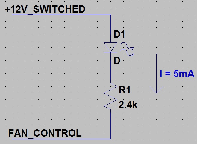
Posted by: 76-914 Jul 6 2015, 02:30 PM
A million thank you's.
Posted by: 76-914 Oct 19 2015, 10:56 PM
Question #10 - After someone posted a question re: the diode behind the light cluster it dawned on me that they also work on the neg path. I have 3 ground wires coming from the ECU that control the fan relays. I never knew which did what so they've all been tied together before connecting to a single relay. I want to tap into each ground so I can see when or what activates each one. What diodes do I need and hopefully a link to a place that sells them. TIA, Kent
Posted by: 76-914 Oct 21 2015, 08:26 AM
![]() back to pg 1.
back to pg 1.
Posted by: 76-914 Jul 13 2016, 06:05 PM
Question #11 - I want to lower my AC fan speeds about 50%. Can I use a 12v to 6v step down transformer to do this? What are your recommendations on how this can be accomplished. TIA
Question #12 - I can read (or so I say) schematics and flow charts but damned if I can draw one.  I want to create a schematic that shows my new conversion wiring and where it ties into the OEM wiring. Has anyone here done that? If I saw how someone else did theirs I'm sure I could extrapolate the info I need from your schematics. Or if not, a link to on "how to" draw schematics would help.
Posted by: 914forme Jul 13 2016, 06:19 PM
https://www.youtube.com/watch?v=hDPEenhFtmg
Question 11 question. Is this the internal A/C fan, or is it the electric fan on the radiator / condenser.
Posted by: 76-914 Jul 13 2016, 06:51 PM
https://www.youtube.com/watch?v=hDPEenhFtmg
Question 11 question. Is this the internal A/C fan, or is it the electric fan on the radiator / condenser.
AC fan. It's a little too much unless I want to ride around with the windows rolled down.
 And thx for the link.
EDIT: OK, I watched the video and I already knew this stuff but boy did I find out something I didn't know. I had incorrectly believed that the energy of a battery flowed out the + side and returned via the - side. Shit, I had that backwards all of these years! The video says it flows out the neg side and returns on the pos side. Who knew?
Posted by: stugray Jul 13 2016, 10:34 PM
EDIT: OK, I watched the video and I already knew this stuff but boy did I find out something I didn't know. I had incorrectly believed that the energy of a battery flowed out the + side and returned via the - side. Shit, I had that backwards all of these years! The video says it flows out the neg side and returns on the pos side. Who knew?
Current is standardized to flow out the positive terminal on a source (battery) through the load and in through the negative terminal.
The electrons are now known to flow out from the negative terminal through the load and in through the positive terminal.
Benjamin Franklin had a 50/50 chance when he guessed and made the standard.
He just got it wrong

If you really want your mind blown consider that in semiconductors current is modeled as consisting of negative electrons flowing one way and positive "holes" flowing in the opposite direction.
The direction of the flow of "holes" in a circuit matches Franklin's standard for current.
As for circuit schematics, check out:
http://www.123dapp.com/circuits
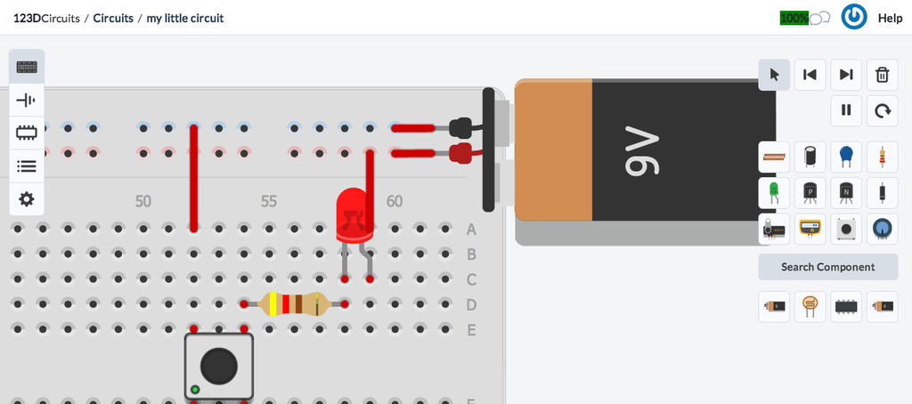
Make an account and you can build basic circuits from a box of virtual parts and a breadboard OR start in schematic editor and add components from there.
You can then run a simulation of the circuit even including an arduino microcontroller complete with code.
If you decide you want a circuit board made, the software can even route the lines to generate the artwork and you can order it online.
It is actually amazing for free.
Posted by: Spoke Jul 13 2016, 11:22 PM
Question #11 - I want to lower my AC fan speeds about 50%. Can I use a 12v to 6v step down transformer to do this? What are your recommendations on how this can be accomplished. TIA
The simplest way to slow the fan for AC is to add a power resistor in series with the fan. My '97 Audi A6 used a power resistor to provide a slower fan speed for the first level of radiator cooling.
To properly size the resistor, one has to know the current draw of the fan at the reduced voltage. Did the fan come with any specifications like current draw or power rating in watts?
For a starting point, let's say the current draw at 6V across the fan is 2A. (a guess)
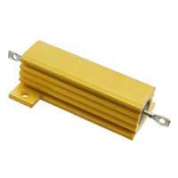
Thus the resistor has to drop 14V - 6V = 8V with 2A flowing. The resistor value needed would be 8V/2A = 4 ohm. The power dissipation of the resistor would be V x I = 8V x 2A = 16W.
In this example, it would be safe to use a 50W resistor like the one below available at Digikey for less than $4. Shipping will cost more than the part. The part below is 4.7 ohm and is just an example. Adjust the numbers above as needed for actual specs or measurements.
http://www.digikey.com/product-detail/en/te-connectivity-amp-connectors/HSA504R7J/A102171-ND/2056014
Posted by: stugray Jul 14 2016, 07:08 AM
The resistor would work, but for about the same amount of $$ you could use a fan speed controller for a computer:
http://www.coolerguys.com/840556089537.html?productid=840556089537&channelid=FROOG& amp;gclid=CjwKEAjw8Jy8BRCE0pOC9qzRhkMSJABC1pvJlGWuXi588f41qE5EjsEPFTUoBAHWzbrvoG
bOjPwizhoCiIjw_wcB
$6 ,but you would just have to find one that can handle the current.
Posted by: 76-914 Jul 14 2016, 07:31 AM
Stu and Jerry; thx a million. I can't wait to play with that link tonite Stu. And Jerry, I need to find that info, digest what you've provided and probably come up with 5 more questions. To quote Arnold S., "I'll be back".
Posted by: 76-914 Jul 27 2017, 01:57 PM
Post #13. I'm at a Baker's Dozen so I'd better start off with thanking everyone of you guys for all of your help. I've learned a lot with your help but once again I'm stumped and need to run this by you genuis'.
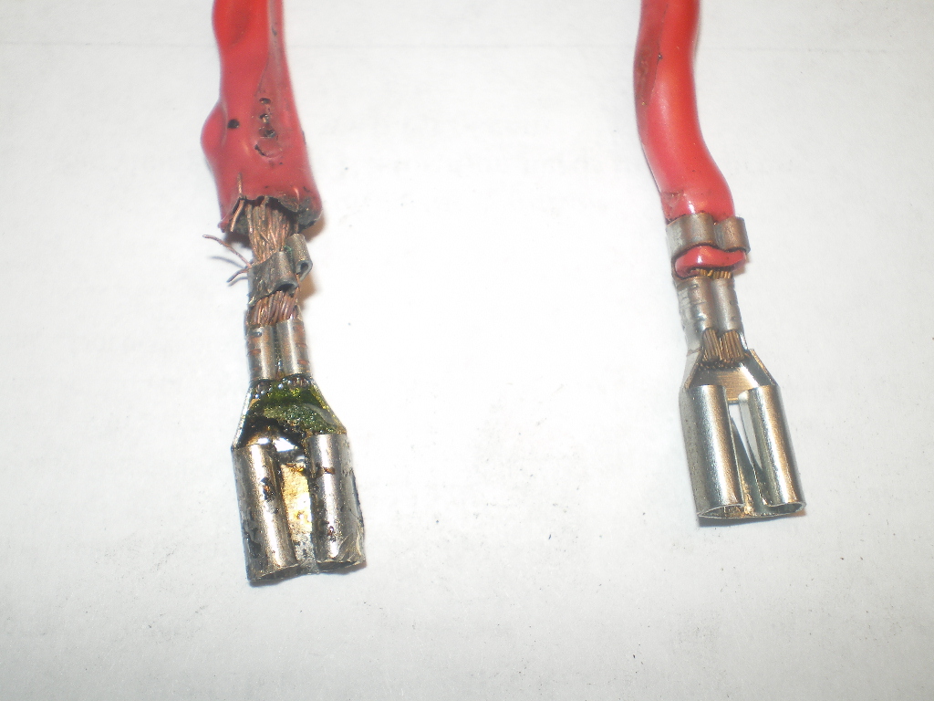
When I turned the ignition switch to "on" yesterday I heard a faint squealing noise from the frunk that continued after starting. My first thought was the fuel pump but after flipping the "fan override switch" the noise stopped as the fans came on. This time my first, or should I say second, thought was that one of the fans had been in a bind after adding the duct work and now cleared. Yea right. So later in the afternoon when charging the AC I flipped the fan override and nothing! Checked the fuse and it was fried. No, I mean fried as in melted and sticking to the plastic fuse holder. Needle nose pliers and a pocket knife later I am treated to this: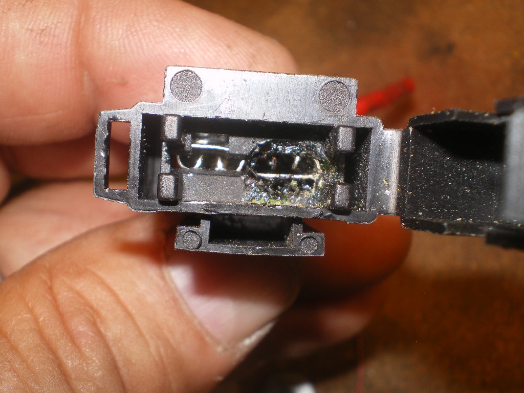
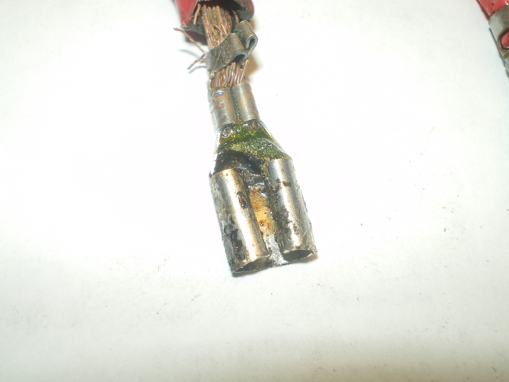
Oddly enough it is on one terminal only and that terminal is the Battery side. As you see in the next pic the wire melted/distorted the insulation a few inches back but the other side is OK. Might be worth mentioning that the plastic holder became hot enough that the spade terminals float in that case and can touch one another bypassing the fuse. Might not matter in this case. 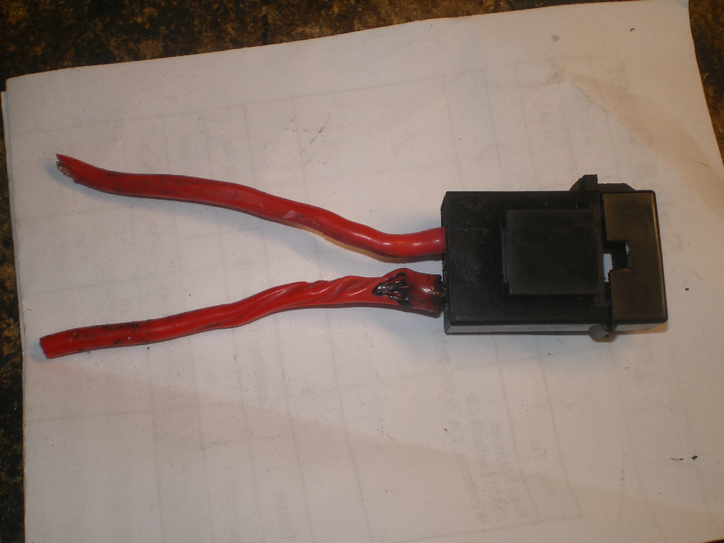
I remember chasing a short last summer that turned out to be this New distribution box. POS. I only mention this because it was a loose connection that eventually separated because of the melting/bubbling of the plastic. This happened because I did not check the tightness of the screws on the back before installing. Anyway, the milky area was the problem area and guess what? That was on the battery side also! 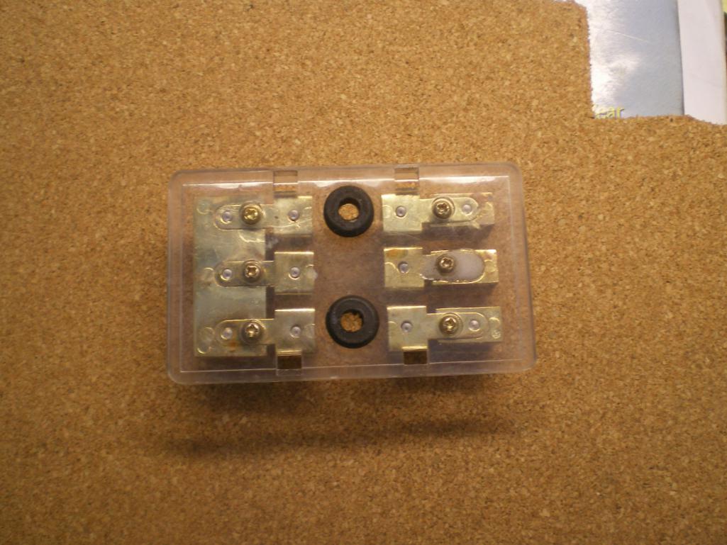
Am I seeing a pattern here? Did I have a bad factory crimp at the spade which caused resistance eventually melting that insulation and shorting out? I'm pulling 9.7A with both fans on, 10ga dedicated circuit, 20A fuse per Derale controller. Another tidbit: the fan controller uses negative switching. I just supplied 12v & ground to it. Relay, fuse and control board are all factory. One last piece of info. The fan controller is mounted on the driver wheel well about 8" from the gas tank. Until I ducted the radiators last week the gas tank would become very hot from the radiator exhaust resulting in vapor lock. Could that have damaged the board? This I ask because of the squealing noise I mentioned earlier. Why did the controller or it's relay squeal? The fan override switch was not on and it was a cold start so it should not have called for them to come on either. I failed to mention that when I first discovered the melt down I replaced the fuse, taped the bare spots and all was normal. However, when I turned the switch to on that evening the squeal returned. I'm replacing that fuse link but it won't be here for a few days so I thought I would run this up the pole for opinions in the meantime. TIA, Kent
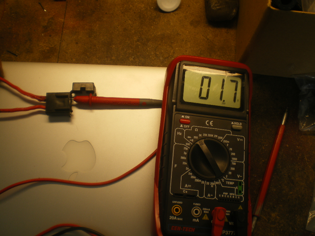
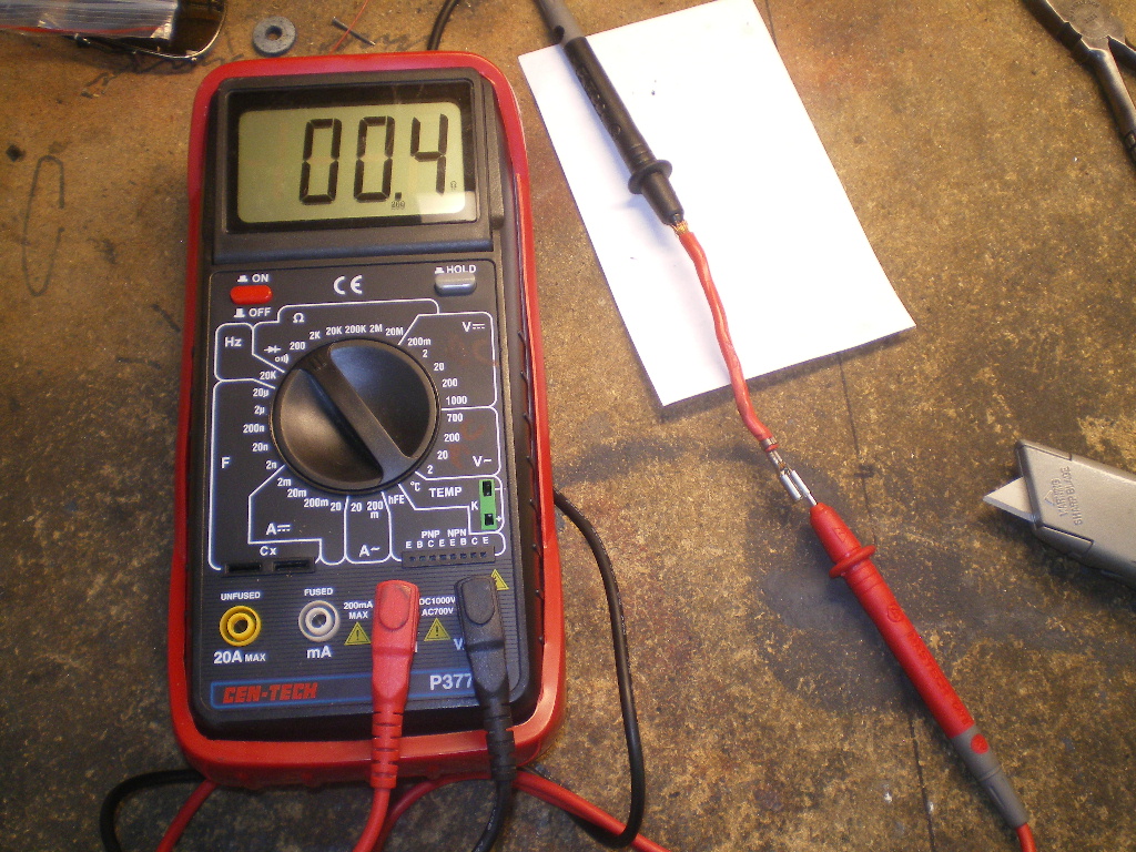
Posted by: 76-914 Jul 27 2017, 10:08 PM
Never mind. Nailed it. I ohmed out the fuse holder since it was removed. Both leads are about 4" long. The fried side was 2.7 ohms the first read but improved to 1.7 ohms after some jostling. The good side was .4 ohms. So at one point that lead had at least 7 times the resistance. And this is the factory's crimp, not mine. There are a few pics showing the readings but look closely at the spade terminals. I roughed up the burned one when I removed it but that mangled ring only clamped the insulation so there was no electrical contact there previous to my horsing it out. When I compared the length of the bare wire in the good spade then held it alongside the bad side it was apparent the wire was only 1/2 way into the crimp ring. You can't see it protruding past the crimp ring as it should. What I do see is some hard green stuff. Maybe residue from the old holder after cooking. I'll break down the crimp on the spade tomorrow to see how far the wire actually went in. Damn it's nice when I figure one out myself. 
Posted by: Spoke Jul 27 2017, 11:39 PM
Good find. That looks like a cheap QC connector. The melted one looks to be a bit bend top to bottom. You can replace the fuse carrier with a high quality fuse carrier like this one from Jegs:
http://www.jegs.com/i/JEGS-Performance-Products/555/10520/10002/-1
Your resistance numbers look a bit high. Did you zero your meter by touching the 2 leads together and noting the resistance? Subtract the shorted-leads resistance from your measurement. Accurately measuring resistance in the sub 1 ohm region is difficult. Lots of times you'll have up to 1 ohm in the leads.
Posted by: 76-914 Jul 28 2017, 08:31 AM
Good find. That looks like a cheap QC connector. The melted one looks to be a bit bend top to bottom. You can replace the fuse carrier with a high quality fuse carrier like this one from Jegs:
http://www.jegs.com/i/JEGS-Performance-Products/555/10520/10002/-1
Your resistance numbers look a bit high. Did you zero your meter by touching the 2 leads together and noting the resistance? Subtract the shorted-leads resistance from your measurement. Accurately measuring resistance in the sub 1 ohm region is difficult. Lots of times you'll have up to 1 ohm in the leads.
I did not touch the two together prior to testing but I will next time. Did not know about that. Thx. Could have been the Chinese VOM, as well. I had it out because it's my only meter that measures DC amp. I'll get my Fluke out to check ohms next time. You know, this electrical stuff is getting interesting! Thx Spoke.
Posted by: 76-914 Nov 20 2017, 07:38 PM
This is one of those subjects that the more I read about it the less I understand so let me state it as simple as my mind works.  The '70 V8 conversion I'm completing has a single wire (internal VR) alternator. The relay board isn't being used so should I delete the "blue" wire connection on the 14 pin connector? I'm using a '73 harness if it makes any difference and will be using a volt meter as well. If it is deleted what else will be required? TIA, Kent
Posted by: 76-914 Nov 22 2017, 09:58 AM
![]()
Posted by: Spoke Nov 22 2017, 07:59 PM
This is one of those subjects that the more I read about it the less I understand so let me state it as simple as my mind works.
The '70 V8 conversion I'm completing has a single wire (internal VR) alternator. The relay board isn't being used so should I delete the "blue" wire connection on the 14 pin connector? I'm using a '73 harness if it makes any difference and will be using a volt meter as well. If it is deleted what else will be required? TIA, KentWhich blue wire on the 14 pin connector are you referring to? Which pin number is it?
If the new alternator with VR only has one wire, that should go to the battery.
Posted by: 76-914 Nov 23 2017, 10:25 AM
Thanks for answering. Electrical issues remind me of how little I know. The blue wire enters as pin #2 on the 14 pin connector which goes to D+ and exits the relay board as a red wire presumably part of the alt harness. I wondered if I should ignore the blue lead or does it need to be connected to complete some ubiquitous circuit I'm unaware of. I do know the single lead goes to the battery but that's about all.
And now another issue. Last night I powered up the 2 main circuits which go to the fuse #11 & #27 steering column. One thing has me baffled. At first the turn signals worked all around. In fact all of the lights work including the pop up headlights. I noticed I had crossed a back up lite with a tail lite and corrected that. A few minutes later I was going thru the various components again and noticed the turn signals weren't working. No illumination at front or rear bulbs when the stalk was moved L&R. No flashing either. The PARK feature does work for the L & R sides and the flasher unit #47 works when the Hazard switch is pulled. So this new question is twofold. Does the power go thru the flasher switch and/or turn signal assm first and then to the flasher unit OR the flasher unit first? 2nd; can the flasher unit work on the Hazard switch but not the turn signal? If I need to test the turn signal assm is there a procedure to follow? TIA, Kent
Posted by: Spoke Nov 23 2017, 11:13 AM
Thanks for answering. Electrical issues remind me of how little I know. The blue wire enters as pin #2 on the 14 pin connector which goes to D+ and exits the relay board as a red wire presumably part of the alt harness. I wondered if I should ignore the blue lead or does it need to be connected to complete some ubiquitous circuit I'm unaware of. I do know the single lead goes to the battery but that's about all.
Ok. All the wiring to/from the 914 alternator and VR will not be used including the GEN light. You really don't need to do anything with them if you don't want to. I hesitate cleaning up wiring unless absolutely necessary as you never know what else uses that wiring.
And now another issue. Last night I powered up the 2 main circuits which go to the fuse #11 & #27 steering column. One thing has me baffled. At first the turn signals worked all around. In fact all of the lights work including the pop up headlights. I noticed I had crossed a back up lite with a tail lite and corrected that. A few minutes later I was going thru the various components again and noticed the turn signals weren't working. No illumination at front or rear bulbs when the stalk was moved L&R. No flashing either. The PARK feature does work for the L & R sides and the flasher unit #47 works when the Hazard switch is pulled.
So this new question is twofold. Does the power go thru the flasher switch and/or turn signal assm first and then to the flasher unit OR the flasher unit first? 2nd; can the flasher unit work on the Hazard switch but not the turn signal? If I need to test the turn signal assm is there a procedure to follow? TIA, Kent2nd question first, the flasher can work with either the 4-ways or turnsignal stalk. They are in parallel. I believe all the wires end up at the 4-way flasher.
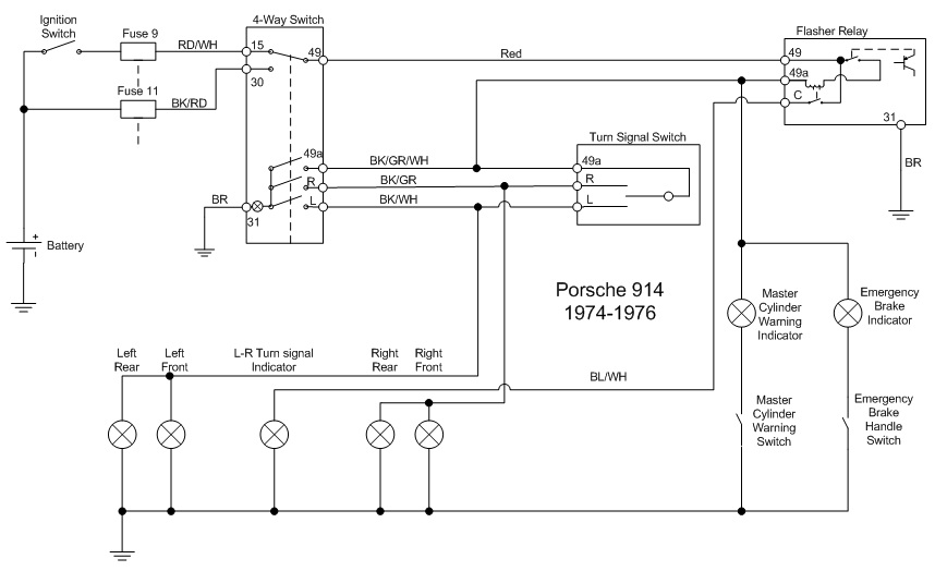
1st question. See the schematic below. Power comes to the flasher first. The red wire from the 4-way switch is just so the 4-way switch can power the flashers with the key off.
I don't think the back up light fix should affect the turnsignals working. Sounds like something else in and around the steering wheel and turnsignal stalk is at issue. If both the L and R turnsignals quit working, it sounds like a connector between the steering wheel and the flasher has come loose.
Attached image(s)
Posted by: 76-914 Nov 23 2017, 01:29 PM
Went back thru it and no power from the black lead which goes to #9 from ignition switch. Could have sworn it had power but none when I checked it this AM. It does have 12v coming to the ignition switch. So apparently I have a starter switch issue to address. Thx for the big pic Spoke. That really helps. I'll report back once I get a new switch installed.
Posted by: 76-914 Nov 24 2017, 02:36 PM
Hey Spoke, the switch was definitely the problem. This AM I went out and jumped #10 (always hot) to #9. Got a snappy spark because I didn't remove the Bk lead from it first. That told me the switch has a dead ground. Pulled the Bk lead from #9 and jumped it again. No spark and the blinkers are functioning again. Thx for the input.
Posted by: 76-914 Aug 8 2021, 05:28 PM
Electrical Problem #15
As stated - I'm totally stumped this time. My '70 914 - which came to me as a V8 - was updated with a 73 steering column and wiring harness. Since I brought it to life - both with the V8 & the current Subaru drivetrain - I haven't been able to get the Fog Lights working and I wonder if I've overlooked something. I'm hoping someone will be able to review this and make some sense of this.
I dropped the Headlight, Emergency and Fog Lamp switches then confirmed that each was wired according to the diagram shown at the bottom - Fig 9.78 of the Haynes Manual. I found the Br wire and the Bk/Bl wires on the Fog Lamp switch were reversed and reinstalled them in their correct positions i.e. Br to post #31 & Bk/Bl to post #15. And sure enough the Fog Lamps came to life when the Headlight switch was on and Hi-beams selected. Satisfied that I'd found the problem I reinstalled all three switches, re-connected the negative battery post only to find that when I tested the Fog Lamps I blew a fuse. Thinking I had been careless and shorted on of the switches or fuse panel upon reinstallation I dropped everything again, replaced the fuse and just like magic everything worked once again. On a whim I checked the Fog Lamp switch with the voltmeter and was surprised to find that the case was live with 12v. And when mounted to the dash it naturally shorted and would blow the fuse.
So it works great as long as it isn't mounted and I guess if I insulated it from the dash it would continue to work but..............that's insane.
After a quick test here are my findings and hopefully this problem will be self evident to someone smart than me. All 3 switches are not mounted and hanging freely during this test :
TEST A
Ign key - On
Headlight switch - On
Fog Light switch removed from circuit.
Gy/R wire from #53 relay - 12v
Bk/Bl wire from post #56 of Headlight switch - 12v
Br wire from post #31 of Emerg flasher switch - 0v but it does have continuity to ground
TEST B
Ign key - On
Headlight switch - on
Fog light switch connected - on
Fog Lights work but as mentioned above the fuse will blow as soon as the switch is mounted as the case is energized with 12v.
My understanding is that the switch only provides a ground to the relay thus completing the circuit. But if that is correct then why am I getting 12v @ the Gy/R wire coming from the relay. TIA for your help.
Posted by: Spoke Aug 8 2021, 06:41 PM
Seems confusing as the foglight switch should not have 12V on the case. There are 3 wires on the foglight switch.
Foglight:
pin 15: goes to the headlight switch and brings 12V power to the switch.
pin K: Is the switched 12V to the foglight relay. Switch in: 15 to K is open circuit; Switch out: 15 to K is shorted.
pin 31: This is ground mainly to light up the switch lamp.
Does the foglight switch lamp light up?
If you think the foglight switch is shorting 12V to the case, remove all wires from the switch and remove the switch. Check the resistance from 15, K, and 31 to the case of the switch. 15 and K should be open circuits WRT the case.
A simplified circuit of the headlights and foglights is attached. Notice that the foglight relay is grounded through pin 86 to the high beam headlights. This way when the high beams are on the foglights should turn off.
Attached thumbnail(s)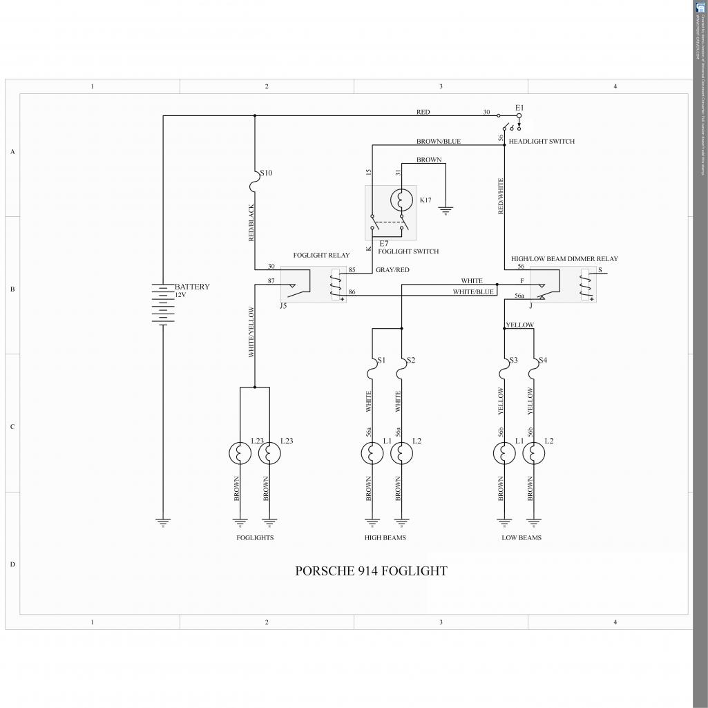
Posted by: 76-914 Aug 9 2021, 01:33 PM
Jerry, With the switch pulled out - on position - I have continuity from all 3 pins to the case. With the switch pushed in - off - I have continuity between pin 31 and the case. Also, when I energized pin 31 with a 9v battery with the switch pulled out - on - I am getting 9v from pins K to the case & from pin 15 to the case. The switch lights up whenever it is pulled out, as it should.
The Wt/Bl that goes to pin 85 on the relay comes from fuse #1. Shouldn't it go to ground? Otherwise the relay has 2 - 12v sources feeding the magnet of the relay.
EDIT: Now I'm wondering if the switch must be bad since the Fog Lamps works as long as the switch isn't mounted and grounded to the panel???
Posted by: ClayPerrine Aug 9 2021, 01:38 PM
#5 - If you own a 914 you know the importance of a good ground. As I went through the Subaru harness I counted over 20 grounding points so Suby has a good idea, also.
My question is this. Are there rules that govern grounds? If so, can a layman understand them? Can a ground junction become ineffective if too many grounds converge at one point? Does a ground need to be sized? Should it be the same gauge as the positive circuit it completes? If adding ground points does the material type matter? e.g. brass, steel. As always, TIA, Kent
You really can't have too many wires going to a ground point. Because it runs through the chassis, you have a huge wire (i.e. the chassis) to run back to the battery ground cable.
The ground wire to the body should be the same gauge as the hot side of the circuit.
Brass is a better connector, but steel is fine. For either of them, make sure you have it clean and shiny before you make the connections.
Clay
Posted by: 76-914 Aug 9 2021, 02:29 PM
#5 - If you own a 914 you know the importance of a good ground. As I went through the Subaru harness I counted over 20 grounding points so Suby has a good idea, also.
My question is this. Are there rules that govern grounds? If so, can a layman understand them? Can a ground junction become ineffective if too many grounds converge at one point? Does a ground need to be sized? Should it be the same gauge as the positive circuit it completes? If adding ground points does the material type matter? e.g. brass, steel. As always, TIA, Kent
You really can't have too many wires going to a ground point. Because it runs through the chassis, you have a huge wire (i.e. the chassis) to run back to the battery ground cable.
The ground wire to the body should be the same gauge as the hot side of the circuit.
Brass is a better connector, but steel is fine. For either of them, make sure you have it clean and shiny before you make the connections.
Clay
Well thx for that info
 Clay but the current question, no pun intended, regards the Fog Lamp circuit.
 Posted by: Spoke Aug 10 2021, 11:34 AM
Jerry, With the switch pulled out - on position - I have continuity from all 3 pins to the case. With the switch pushed in - off - I have continuity between pin 31 and the case. Also, when I energized pin 31 with a 9v battery with the switch pulled out - on - I am getting 9v from pins K to the case & from pin 15 to the case. The switch lights up whenever it is pulled out, as it should.
The Wt/Bl that goes to pin 85 on the relay comes from fuse #1. Shouldn't it go to ground? Otherwise the relay has 2 - 12v sources feeding the magnet of the relay.
EDIT: Now I'm wondering if the switch must be bad since the Fog Lamps works as long as the switch isn't mounted and grounded to the panel???
Not sure what is going on with your switch. What resistance do you measure when you state "I have continuity between..."? I assume you're using a VOM.
Try this test with your 9V battery. Configure your VOM for amps and put the battery POS through the VOM (to measure current) and the other lead of the VOM to pin K and the NEG of the battery to the case. What current do you read?
Do the same with pin 15.
Posted by: 76-914 Aug 10 2021, 04:15 PM
Jerry, With the switch pulled out - on position - I have continuity from all 3 pins to the case. With the switch pushed in - off - I have continuity between pin 31 and the case. Also, when I energized pin 31 with a 9v battery with the switch pulled out - on - I am getting 9v from pins K to the case & from pin 15 to the case. The switch lights up whenever it is pulled out, as it should.
The Wt/Bl that goes to pin 85 on the relay comes from fuse #1. Shouldn't it go to ground? Otherwise the relay has 2 - 12v sources feeding the magnet of the relay.
EDIT: Now I'm wondering if the switch must be bad since the Fog Lamps works as long as the switch isn't mounted and grounded to the panel???
Not sure what is going on with your switch. What resistance do you measure when you state "I have continuity between..."? I assume you're using a VOM.
Try this test with your 9V battery. Configure your VOM for amps and put the battery POS through the VOM (to measure current) and the other lead of the VOM to pin K and the NEG of the battery to the case. What current do you read?
Do the same with pin 15.
Jerry, I had an extra switch so I opened it up to see how it worked. What I found was that when the switch is in pushed in 31 & 15 are connected. When the switch is pulled out K joins the crowd & makes a connection to 15 & 30. And of course the body is connected to these as well. So once the switch is pulled out they all connect to one another. I don't understand how this could possibly work unless it has something to do with one of those diodes behind the Tach. I was sure that I'd find the 12v pin isolated from the ground pin next to it and that the switch would make contact between the 2 grounds when pulled out but it didn't work that way.
Either way this is above my pay grade and noting made any sense to me. When I checked resistance to the case I had the VOM set on 200 and if I read it correctly it was 1.46. I checked this with 2 different digital VOM's. I also checked it with the audible setting which is what I referred to as continuity between the pins and/or case. I eliminated the 12v Bk/Bl from the circuit and just switch between the Br & Gy/R which activates the relay and energizes the Fog Lamps. I'll post up some pics of the switch internals so you can see what I trying to say. BTW, what should I have set the ohm scale to when checking resistance? TIA, KentEDIT: I'll check the current with the 9v battery tomorrow and get back to you with the results. Thx again.
Powered by Invision Power Board (http://www.invisionboard.com)
© Invision Power Services (http://www.invisionpower.com)