Printable Version of Topic
Click here to view this topic in its original format
914World.com _ 914World Garage _ 72 Vacuum hose diagram, Heat exchanger torque spec
Posted by: 914bub Jun 26 2014, 10:52 PM
So I've searched and searched online and I can't find an engine vacuum hose diagram for my 72 914, (1.7). If anybody can help me out I would greatly appreciate it.
I am also looking for a torque spec for the nuts that attach the heat exchangers to the heads.
Thanks in advance! Bub
Posted by: type47 Jun 27 2014, 04:39 AM

... torque spec for the nuts that attach the heat exchangers to the heads.
18 ft-lbs (number I read from Jake awhile ago)
Posted by: cary Jun 27 2014, 06:56 AM
Hose diagram.
http://www.pelicanparts.com/914/technical_specs/914_17FI_diag.htm
Posted by: 914bub Jun 27 2014, 01:19 PM
Hose diagram.
http://www.pelicanparts.com/914/technical_specs/914_17FI_diag.htm
Thanks. I've got a copy of that particular diagram printed out already but I thought there was a hose or two going to a fuel pressure regulator or ??? that is mounted near the MPS?
Posted by: cwpeden Jun 27 2014, 01:44 PM
Hose diagram.
http://www.pelicanparts.com/914/technical_specs/914_17FI_diag.htm
Thanks. I've got a copy of that particular diagram printed out already but I thought there was a hose or two going to a fuel pressure regulator or ??? that is mounted near the MPS?
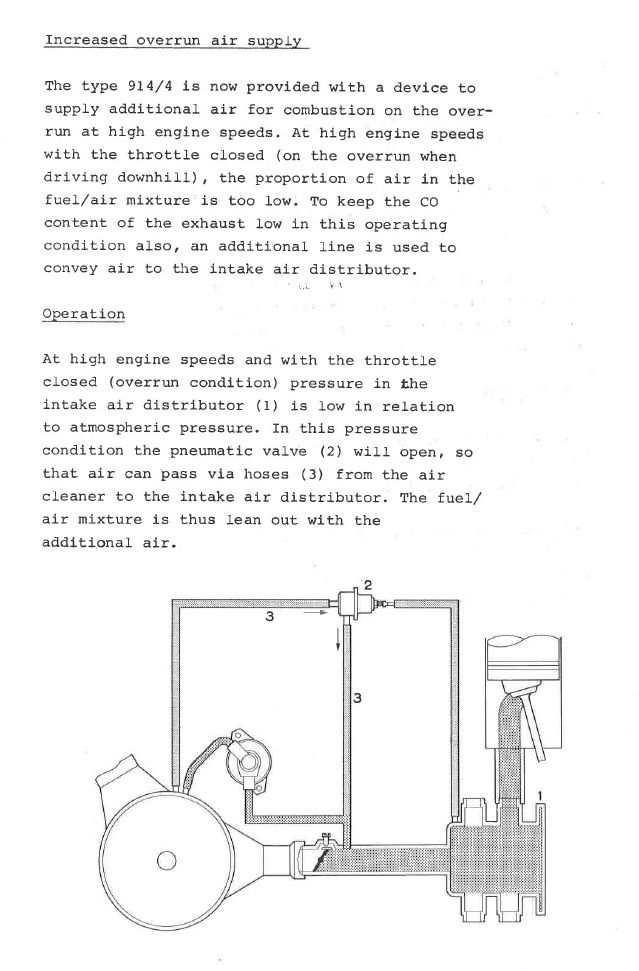
Sounds like the decel valve. See here in 2.0L format. http://www.pelicanparts.com/914/technical_specs/914_20FI_diag.htm
Posted by: Dave_Darling Jun 27 2014, 03:14 PM
The two large hoses to the decel valve may be swapped in that diagram, BTW...
--DD
Posted by: Cap'n Krusty Jun 27 2014, 03:25 PM
Those 2 hoses are of different diameters, IIRC, so there shouldn't be any confusion. Did the '72s even have a decel valve? If so, where was the tap for the small hose? The '72 was a one year only version and had a temperature controlled vacuum switch in the air cleaner for the heat riser. That tap was in the rubber hose between the AAR and the intake plenum.
The Cap'n
Posted by: Jeff Bowlsby Jun 28 2014, 08:09 AM
The 1972 Service and Training Manual clearly depicts the decel valve as new for 1972.
Posted by: rhodyguy Jun 28 2014, 08:23 AM
agreed on the 18#. torque them down in a few stages, increasing the value, in an X type pattern as to not bind and build in a leak.
Posted by: Cap'n Krusty Jun 28 2014, 09:43 AM
The 1972 Service and Training Manual clearly depicts the decel valve as new for 1972.
OK. The manual has a better memory than I do after 42 years. Where's the vacuum tap for the 3.5 mm hose?
The Cap'n
Posted by: Jeff Bowlsby Jun 28 2014, 10:06 AM
The 1972 Service and Training Manual clearly depicts the decel valve as new for 1972.
OK. The manual has a better memory than I do after 42 years. Where's the vacuum tap for the 3.5 mm hose?
The Cap'n
This is the page from the '72 S&T manual...its probably more diagrammatic than anything.
Attached image(s)
Posted by: Cap'n Krusty Jun 28 2014, 10:50 AM
AHA! That's NOT for a '72, at least the ones sold in CA (and probably the US, too). Note the lack of vacuum plumbing for the thermostatic air cleaner, which was installed ONLY on the '72s. There's a date on the S&T manual. What is it?
The Cap'n
Posted by: Jeff Bowlsby Jun 28 2014, 10:58 AM
AHA! That's NOT for a '72, at least the ones sold in CA (and probably the US, too). Note the lack of vacuum plumbing for the thermostatic air cleaner, which was installed ONLY on the '72s. There's a date on the S&T manual. What is it?
The Cap'n
Here is the whole manual...it has that funky thermostatic thingy in it too...
Attached File(s)
 1972_ServiceInformation.pdf ( 912.63k )
Number of downloads: 25
1972_ServiceInformation.pdf ( 912.63k )
Number of downloads: 25Posted by: Cap'n Krusty Jun 28 2014, 03:07 PM
It's interesting the diagram for the TAC is the one used for a Type 1. We still don't know where that pesky tap goes. Thinking about it, perhaps the tee is the tap for that, and there's an extra tap in the plenum. Maybe Bruce Stone has one to look at.
The Cap'n
Powered by Invision Power Board (http://www.invisionboard.com)
© Invision Power Services (http://www.invisionpower.com)