Printable Version of Topic
Click here to view this topic in its original format
914World.com _ 914World Garage _ Magnetic fired ignition
Posted by: -JR- Jan 20 2005, 01:27 AM
I've been putting together my new 2+ litre engine and have been looking into flywheel fired magnetic ignition. The crank fired ignition won't work too well I guess since the front of the engine is buried in air ducting.
I am contemplating installing two of http://www.msdignition.com/mag_6.htm into my flywheel to run a MSD 6AL system.
There is a nice inspection hole on one half of the case that would be perfect to mount a pickup in.
Anyone tried this beofre and if so any pics or suggestions?
Thanks!
-JR-
Posted by: Jake Raby Jan 20 2005, 01:39 AM
I have incorporated BMW parts to make it work... No real benefits.
I use the Electromotive HPV 3 system to do my direct fire duties. I make the adaptors and crank wheels for a TIV for those.. It has totally adjustable advance curves and rev limiting from the dash..
Posted by: -JR- Jan 20 2005, 01:53 AM
What sort of BMW parts did you incorporate? (Year's / model)
Any shots of that pickup assembly available?
Thanks!
Posted by: TimT Jan 20 2005, 02:11 AM
You could put the 4 magnets (4 magnets is you need a "home" signal 3 if you just need the firing interval) in the flywheel, and then use any number of pickups for the trigger.
The 3.2 and later /6's use a toothed wheel on the flywheel for the ignition/timing signal. No reason you cant use magnets in this case
Posted by: -JR- Jan 20 2005, 02:23 AM
Thanks for the note.
Four sensors are required for a V8, 3 for a 6 and 2 for a 4 banger. One at TDC and another at 180 from that. At least that's what the MSD system requires to make it all happen.
I understand that Porsche started the breakless ignition with the 3.0 engine.
-JR-
Posted by: Jake Raby Jan 20 2005, 02:34 AM
I did it like 8 years ago..
I think it was 320 parts..
Posted by: TimT Jan 20 2005, 02:42 AM
Yes the breakerless ignition did start earlier than the 3.2, but the 3.2 and later engines used motronic engine management, and the spark was controlled by the brain. the distributor only sent the spark to the appropriate cylinder. The brain controlled advance etc. The signal to the brain was taken from the teeth cut into the edge of the flywheel, (60 minus 2 teeth) the missing two teeth told the computer when to start the firing events.. the gap was "home" and that cylinder 1 was approaching TDC
I dont know if the msd needs a home signal, it appears not to. but if a home signal is needed, so the engine will know when the first spark event should occur, then an extra magnet is needed.
ie 5 for an 8 cylinder, 4 for a 6, 3 for a 4 cylinder etc.
if no home signal then 4 for an 8, 3 for a 6 etc..
Posted by: Mark Henry Jan 20 2005, 06:10 AM
I have it on my SDS system....it was a total PITA to do.
My way is a bit hacky but it works fine...when I do my big four I'm going to build a better mount and use a modified 911 pully for the trigger wheel.
Attached image(s)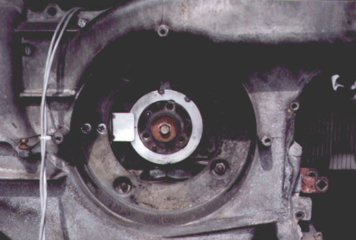
Posted by: Mark Henry Jan 20 2005, 06:13 AM
back
Attached image(s)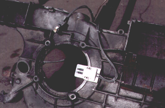
Posted by: Mark Henry Jan 20 2005, 06:16 AM
back installed
Attached image(s)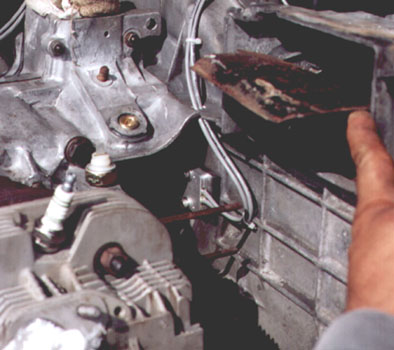
Posted by: Mark Henry Jan 20 2005, 06:22 AM
I know it doesn't look that bad but to adjust the pick-up you have to take the shroud apart. Once set it's no big deal.
On my new set-up I want to fab a heavier sensor mount and make the whole thing bullet proof. I've had no problems with it, but I like to go on all day 300+ mile road trips and the last thing I want is to be stuck on the side of the road.
Posted by: -JR- Jan 20 2005, 01:49 PM
Thanks very much Mark!
The parts you are using, are they "borrowed" from something else or did you put them together yourself?
-JR-
Posted by: Mueller Jan 20 2005, 02:23 PM
Ben M. has mounted 2 or 4 magnets on his fan for his ignition.
As you saw in Marks post he has mounted his behind the fan.
Dave Hunt has his trigger wheel behind the fan....the picture is of my install on a spare motor. Daves setup is up and running (both are for using the Ford EDIS parts)
Marks system is an http://www.sdsefi.com/ unit.
You can still mount the magnetics on the flywheel, but what system are you going to run? Someone else on the board adapted a Chevy ignition into his car, and just about anything can be adapted, the question is can you tweak the advance/retard to match your engine if you need to?
Attached image(s)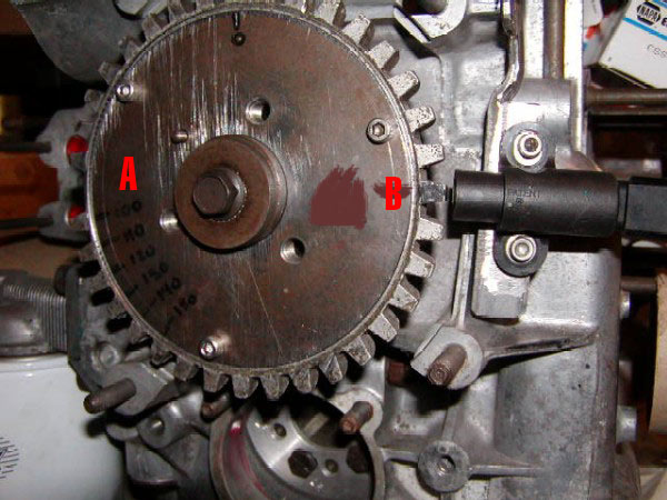
Posted by: lapuwali Jan 20 2005, 03:20 PM
I wonder if a suitable setup would be to mount magnets on the fan, and point the sensors down through a plug machined to fit the timing hole in the shroud. Two sensors, one "south pole" sensitive, the other "north pole" sensitive. One could arrange a system where "north" was 1/4, and "south" was 2/3, with the magnets about 40-50d BTDC. This would give enough data for wasted spark and bank-fire injection. Wouldn't work with EDIS or SDS, and probably not with any other off-the-shelf system, but some custom code for the MS hardware would work with this. A modification with three magnets could accomodate SDS. The two magnet setup would be REALLY easy to generate the D-Jet trigger points signal from, so one could make distributorless ignition for D-Jet.
Hmm...
Adjusting the sensors would require machining a new plug, but as long as the sensors and magnets aren't off by more than a few degrees, adjustment could be made in software.
Big question is (don't have a car handy): can you get the sensors close enough to the back rim of the fan from the timing hole to sense the magnets accurately? You probably don't want to mount a magnet to a fan blade, and the thick "pillars" aren't conveniently located.
I'm turning into Mueller. I'm considering going Soob, but still thinking about Type IV EFI systems...
Posted by: Mark Henry Jan 20 2005, 04:38 PM
Believe me I thought about almost every way to mount my sensor.
The opening in the shroud for the fan is smaller than the fan itself.
To mount it to the fan you would have to cut out a slot on the rim of the fan opening (the shiny part were my sensor is mounted) on the shroud. You have to set an air gap, making most other areas on the shroud/fan pretty well imposable to get at for this. The flywheel has the same problem...you can do it (not with SDS) but it's damn near imposable to set your air gap.
The trigger disc set-up was the only way I could over come this problem.
Like I said next time I'll use a 911 pulley for the trigger disc. It bolts right on, but you would have to cut the back of the fan hub mating surface down something like .050
Posted by: airsix Jan 20 2005, 10:58 PM
Well if Mark thinks his is a hack he'd crap if he saw mine! Yep, as Mueller said, I mounted my magnets in the lip of the fan pulley and put my sensor on the outside of the cast aluminum fan shroud (dead center bottom). It's real easy to adjust from under the car. Hacky as it is it works great. Engine idles much more smoothly than when I was using an optical in the distributor and I have more confidence in the timing accuracy at redline because the bounce and wander is gone.
-Ben M.
Posted by: -JR- Jan 21 2005, 12:11 AM
That's all pretty good feedback. Seems like everyone wants to mount the pickup on the fan assembly side of the engine.
My idea, I think, is much more simple and adjustable.
I want to mount the two magnets in the flywheel with the correct advance for "normal" ignition. I will line up the magnets with the sight hole in the case, where you can see the flywheel. The sensor will be on a simple mechanically adjustable base, to advance or retard the ignition point.
I plan on using a MSD 6AL ignition unit, which is designed for a magnetic pickup. I don't believe you can adjust the timing with the 6AL unit though, so the simple mechanical adjustment should be sufficient.
SDS, on their website that black Porsche race car (the second picture down) is a local guy who introduced me to it. I plan on some day running that on the 3.2 upgrade I want to do next year. But it will run with the stock ECU's first I think.
With the fan mounted ignition, there doesn’t seem anyways to adjust the pickup physically.
Thanks!
-JR-
Posted by: scott thacher Jan 21 2005, 12:39 AM
| QUOTE (lapuwali @ Jan 20 2005, 01:20 PM) |
| I'm considering going Soob |
come to the dark side
 175 hp no valves to adjust, better gas milage, a porsche and vw design ( or so i have heard ) and 150 k miles with no rebuild for 2500 or less
Posted by: Mueller Jan 21 2005, 12:50 AM
| QUOTE |
| With the fan mounted ignition, there doesn’t seem anyways to adjust the pickup physically. |
once setup, you should never have to adjust it...the only thing you might have to do is replace a sensor if it failed, but there is not too much to go wrong with them.
what FI are you running?
Posted by: -JR- Jan 21 2005, 01:27 AM
No FI, just dual webbers! But I want to port the system over to a stock 3.2 setup when I install that in 2006.
As per the adjustment it will undoubtedly require "tweaking" for max power. So that's the real purpose for the adjustment. It would be very hard to adjust the pickup if it's mounted in the fan assembly.
-JR-
Posted by: lapuwali Jan 21 2005, 10:56 AM
| QUOTE (-JR- @ Jan 20 2005, 11:27 PM) |
| No FI, just dual webbers! But I want to port the system over to a stock 3.2 setup when I install that in 2006. As per the adjustment it will undoubtedly require "tweaking" for max power. So that's the real purpose for the adjustment. It would be very hard to adjust the pickup if it's mounted in the fan assembly. -JR- |
The MSD 6AL box has, by itself, NO provision for an advance curve. With it and their crank trigger, you get a fixed advance ignition. This is fine for a drag racer (which is what they advertise it for), but would completely suck on the street. It would be difficult to start, esp. when cold, and would run poorly at low revs. Driving it in stop-and-go traffic would be maddening. On a Type IV, you'd probably end up with a dead engine in short order.
To get an ignition curve, they offer yet another box (actually several variations on it) that can give you anything from a fixed-at-the-factory curve to one you can program yourself.
In the end, you're looking at about $500 to get an adjustable, crank-fired ignition with a distributor to, er, distribute the spark. No vacuum advance. With the "programmable timing computer", you won't have to adjust the sensor once it's in place and the air gap has been set (which is a one-time, engine-off deal). The programmer allows you to adjust the timing completely w/o touching the sensor.
I thought all of this was way overpriced until I started looking at how much the competing setups were. I had no idea an Electromotive HPV was $900 these days. That's insane. No wonder MS is so popular.
If you want a much cheaper ignition only setup that does require soldering and more work to make, look at http://picasso.org/mjlj/index.jsp, which is a distributorless, completely programmable DIY box based on EDIS. Total cost will be under $300, and the end result is a superior system to the MSD thing. No distributor, vacuum advance, and you set the advance curve to anything you want in software.
Powered by Invision Power Board (http://www.invisionboard.com)
© Invision Power Services (http://www.invisionpower.com)