Printable Version of Topic
Click here to view this topic in its original format
914World.com _ 914World Garage _ anyone played with boxster gauge cluster?
Posted by: skeates Jul 29 2014, 09:57 PM
Hey guys - I'm not sure if this is a subject that has been beaten to death before (I certainly wasn't able to find any threads on it), but has anyone here ever attempted to make use of the boxster or cousin 996 gauge clusters in a conversion? I was able to find a pin-out diagram for the boxster cluster which makes it look doable. Just curious if there was any fancy shmancy communications between the cluster and the ECU that would need to be worked around?
Posted by: Dave_Darling Jul 29 2014, 10:14 PM
Depending on the year of Boxster/996, the answer about the fancy schmancy comm protocols is either "probably" or "oh heck yes!"
--DD
Posted by: jd74914 Jul 30 2014, 06:02 AM
I would be highly surprised if the newer stuff didn't communicate with the engine and possibly transmission or any body control units via CANBUS. That said, if you are a software guy, CAN converters do exist and it's my understanding that reverse engineering CAN protocols isn't too bad.
Does your pinout have a CAN+ and CAN- wire?
Posted by: stugray Jul 30 2014, 07:16 AM
If you have the pinouts, please post them.
I have some knowledge about CAN bus and modifying interfaces.
Is this for a conversion of some type, or just a stock 914.
Posted by: Mike Bellis Jul 30 2014, 07:45 AM
I'm running a 2000 VW cluster and it does communicate with the ECU via can bus.
I guess the Boxster can be hacked. Chip Foose did it on a Lotus build.
Please post the pin out for reference.
Posted by: skeates Jul 30 2014, 02:45 PM
@ Dave_Darling: I figured anything 2004 or newer would be strait-up CANBUS, but I'm holding out hope for the first gen clusters.
So, below I've attached the pin-out diagram for a first gen boxter ('97 986). I also managed to locate some pdfs of what I assume is the factory service manual with additional info on diagnosis/troubleshooting of the instrument cluster.
I know going into this that the speed and odometer functions and their derivatives all use an input signal from the ABS system that would need to be replicated. Pretty sure that's just gonna be some sort of PWM. Aside from that many of the remaining pins seem to be binary (hi/low) inputs? Right now I'm thinking these pins are the possible "problem" pins with signals to be dealt with:
- ASR/ABO info (Plug I, pin 3)
- ASR/ABO-SILA (Plug I, pin 4)
- Speedometer A (Plug I, pin 13) ??? <- this may just be for the speed warning indicator?
- K diagnosis (Plug I, pin 21) <- could be for output?
- KVA DME (Plug II, pin 13)
- TN Signal speed (Plug II, pin 15)
- Information system in (Plug III, pin 6)
- Idle period (Plug III, pin 26)
I suppose I'd also need to figure out which pins need a signal for the cluster to operate at all vs. which ones can be left blank (albiet at a loss of some functionality). Anyone versed in Boxster electrical wiring?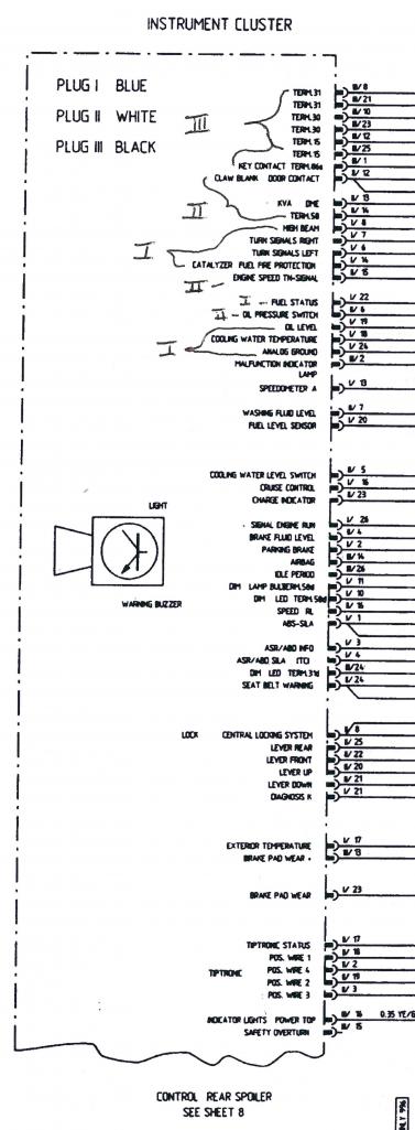
Posted by: skeates Jul 30 2014, 02:48 PM

If you have the pinouts, please post them.
I have some knowledge about CAN bus and modifying interfaces.
Is this for a conversion of some type, or just a stock 914.
This will be for my suby conversion. I'll be running a stand-alone ECU from AEM Electronics (http://www.aemelectronics.com/?q=products/programmable-engine-management-systems/infinity-ecu/infinity-6-8h). The engine is a normally aspirated EZ36 H-6.
Posted by: jd74914 Jul 31 2014, 07:41 AM
You are running an Infinity? Which one?
We looked at those for use on a racecar because of their extreme power, but were somewhat turned off by the lack of sophistication of traction control and lack of gearbox control (sequential tranny). I'm very interested to see how your install works out!!
Posted by: CptTripps Jul 31 2014, 09:14 AM
Looking forward to seeing progress. Those clusters aren't much $, so if this could get worked out, it would be huge for Subie conversions and 6 conversions alike.
Posted by: skeates Jul 31 2014, 10:19 AM
You are running an Infinity? Which one?
We looked at those for use on a racecar because of their extreme power, but were somewhat turned off by the lack of sophistication of traction control and lack of gearbox control (sequential tranny). I'm very interested to see how your install works out!!
I'm planning on using the Infinity-6 that came out earlier this year. Since I'm not building a track-car the traction control bits didn't play into my decision making. When you look at it, these are pretty awesome engine management systems for the price tag!
Posted by: jd74914 Jul 31 2014, 11:23 AM
You are running an Infinity? Which one?
We looked at those for use on a racecar because of their extreme power, but were somewhat turned off by the lack of sophistication of traction control and lack of gearbox control (sequential tranny). I'm very interested to see how your install works out!!
I'm planning on using the Infinity-6 that came out earlier this year. Since I'm not building a track-car the traction control bits didn't play into my decision making. When you look at it, these are pretty awesome engine management systems for the price tag!
Nice! Yeah, my decision was admittedly very biased by the track bits. They do look very, very nice, and are certainly attractively priced!
Posted by: skeates Sep 3 2014, 05:44 PM
Ok, I bit the bullet and purchased a boxster gauge cluster off of evil-bay and for the last week or so I've been fiddling with it. The cluster (and surround) came out of a '97 Boxster, though anything up to the first part of '99 should be the same (has blue, white, and black plugs on the back).
First impressions is that the electrical aspect "should" be a cinch. After a few hours of fiddling with the cluster and a bread-board I was able to get it to turn on and start sorting out the signals. Even sort-of got the tach and speedo going. I say "sort-of" because all I have right now to generate a signal is an arduino board which can only produce a 5 V pulse-width signal. From what I can gather the cluster is expecting a 10 V signal, so the speedo only ever registered 48 MPH and the tach was a bit erratic. Next step is to swing by an electronics store to pick up an op-amp and some potentiometers so that I can simulate the different senders and test the fuel and coolant temp gauges. Also, this thing has an integrated outside air temp gauge that I'd like to get working (I'll provide some pics and video once things are set-up).
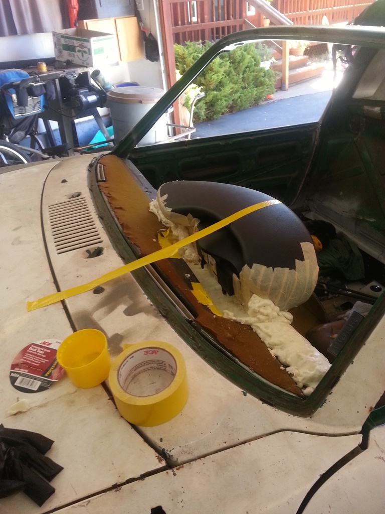
In the mean time I've been tackling fitment. Looking at the cluster, I'm not sure that it would fit without a custom dash-top. Since I was planning to get a bit crazy with my interior anyways I went ahead and made sure that my cluster came with the original surround and I'm experimenting with how to incorporate it into the dash. Here is some of my preliminary progress: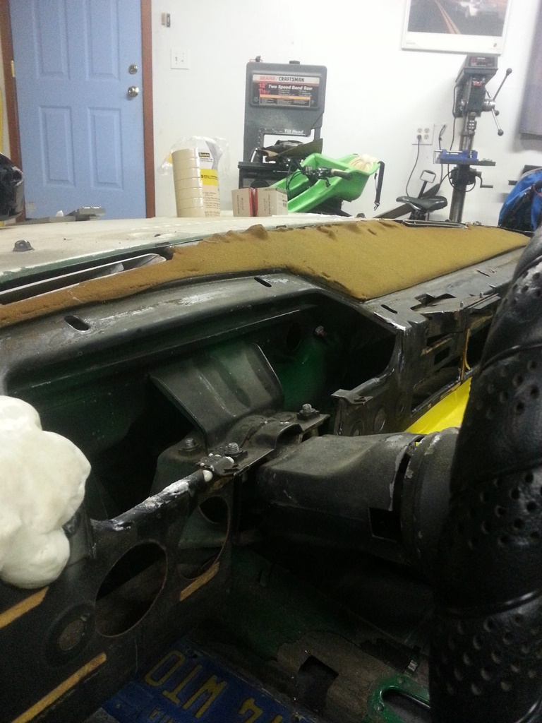
Posted by: skeates Sep 3 2014, 05:52 PM
The local hardware store was having a sale on the spray-foam insulation stuff, so I bought a bunch of it to use for shaping my new dash. This is my first time doing this, so I'm hoping things turn out, but so far it's been pretty easy to work with - just got to remember that it's sticky as hell (hench why I lined every nook and cranny of the cluster with masking tape before setting in the goo). The plan is to make a center console a-la Carrera GT style. So I fashioned a fancy pancy cardboard version to taste and then filled it with the spray foam as well for final shaping. Still a lot more shaping and whatnot to do before anything is ready for fiberglass, but the big picture is starting to become clearer now.
Will post more as I make progress (provided folks are interested).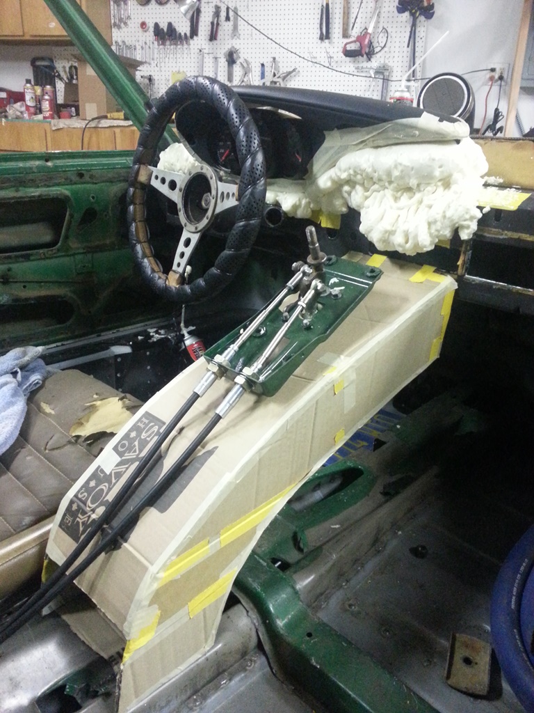
Posted by: Dave_Darling Sep 3 2014, 06:14 PM
One thing I have heard that is important here, if it's true: The expanding foam will continue to expand, slowly, for weeks.
--DD
Posted by: skeates Sep 3 2014, 06:26 PM
One thing I have heard that is important here, if it's true: The expanding foam will continue to expand, slowly, for weeks.
--DD
Thanks for the heads-up Dave - I'll have to keep an eye on things. The can indicates that it takes 8 hours to cure so I've been spraying and then letting it sit over night before doing any shaping. I haven't noticed any movement with the stuff I've already shaped, but maybe it just hasn't been long enough yet.
Posted by: skeates Sep 15 2014, 01:07 PM
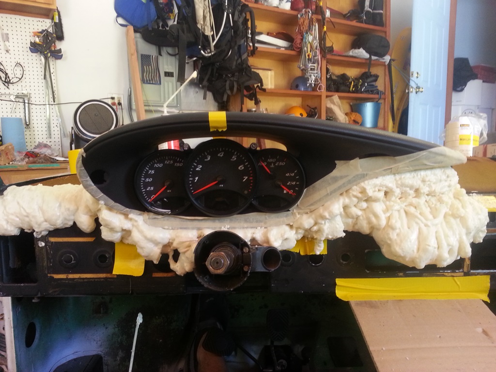
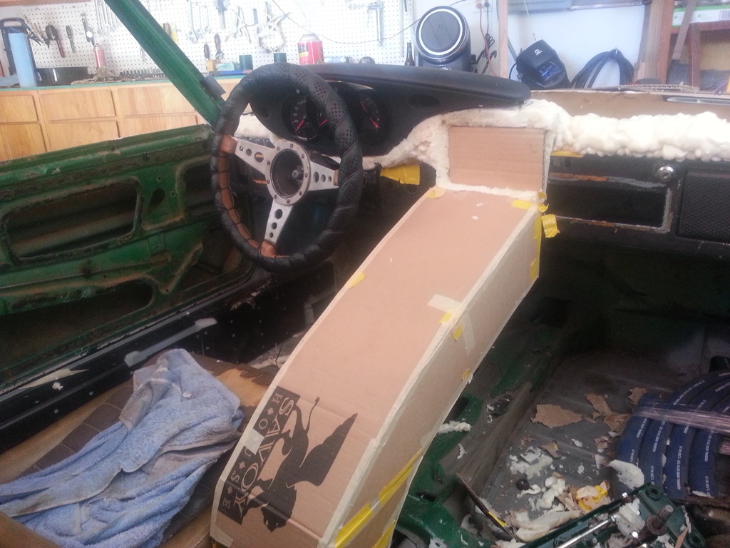
So, until someone tells me this is cluttering up the web I'm going to keep posting my progress  . Made a bit more progress on the boxster gauge cluster this weekend. First things first; even though I'm making a custom dash cap I figured I'd check to see how close this thing fits within the stock set-up. I figured if it fits that would open up a world of opportunities to those wanting to update their gauges, and stick with the Porsche feel without having to make a custom dash. So...I dug out the mounting plate for the stock gauges just to see how close the fit was (see first pic). It's hard to see in the picture, but there are two issues as I can tell which would make it difficult (though not necessarily impossible) to use this with the stock dash cap.
1) The toggles on the top of the cluster (for setting the clock, adjusting brightness, etc.) line up just about perfectly with the two top mounting screw holes. This wouldn't be too hard to work around since you'd be fabricating a custom surround to mount the gauges. At that time just move/make new tabs on the dash frame that line up. Done.
2) The second issue may be somewhat more difficult to work around. Looking at the bottom of the picture you can see that the pod housing the warning lights sticks out slightly below the bottom of the mounting plate. The boxster cluster is just a little bit too tall from what I can tell to fit within the stock dash cap - but it's such a close fit! So close that without an actual dash cap to play with I can't make any final conclusions on the possibility of making this thing fit with the stock dash cap. (if anyone wants to head up to Truckee, Ca with a stock cap to test this out with feel free to swing by  )
)
So, onto the fun stuff - electricity! I've spent more time then I care to think about tracing the boxster wiring diagrams and trying to piece together what's needed and what's not. There are several power inputs, (2) which are constant +12V and (3) more which are powered when the key is in the ACC/Drive position in the ignition. Also, there are (2) grounds for the cluster and an additional "ground" for the sender units (fuel, coolant temp, etc). In order to keep strait the mess of wires I manually pinned out and labeled each wire through the connectors. While doing so I found that many of the expected wires/inputs were "missing" from my pins. Some of these are for inputs from the tiptroic transmission which I expect to be missing on a manual cluster. Others though I think are related to the on-board computer option. At this point I'm just worried about basic functionality, so I'm not paying a whole lot of attention to the missing inputs, but they may become important later if the cluster is expecting an input that I'm not delivering. Note my pig-tails are out of a different '97 manual boxster than the gauge cluster, so there could be some miss-match happening if the options on the cars were different. Below there's a picture of my test-rig (basically just a bread board to facilitate quick & easy circuits and and arduino board that I'm using as a signal generator to simulate speedo and tach signals.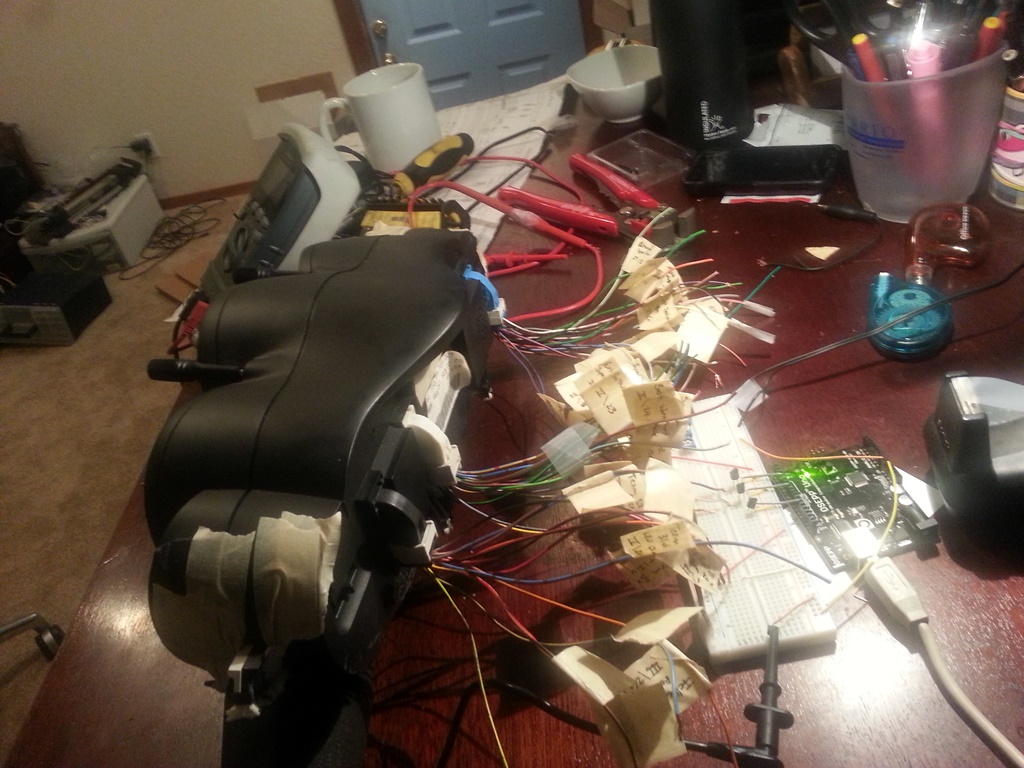
With the gauge cluster powered I then went through at tested the voltage at each (well most anyways) wire to see if any were powered. After doing this I found out something very interesting - most of the indicator lights, the speedo signal, and the tach signal are all powered and expect a ground as their "input". In the case of the speedo and tach they need to be pulled down to ground at a certain frequency, like a flickering light switch, which corresponds to the speed of the car/engine. I'm not sure whether or not this is "normal" for these types of signals, but I was expecting to have to produce a +12V signal to each, not a ground. It actually made it easier in a sense since all I needed to do was use a general purpose transistor as a switch and feed it a PWM signal from the arduino. I addition to those signals, I also got some potentiometers out to simulate the coolant temp and fuel senders. The pic below shows everything running...sort of...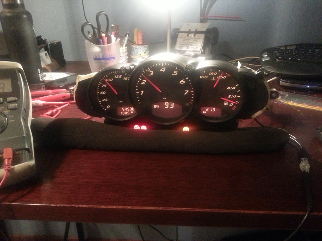
So, the moral of this story is that I've been able to get all the basic functionality working! I've got an Excel spreadsheet I use to calculate at what frequency the PWM signal needs to operate to simulate a specific MPH or RPM. I've also got the coolant temp gauge sender resistance values figured out, the gauge back-lighting/dimming is working, indicator lights are all functional, as well as the turn-signals/high beam indicators, etc.. But....and so far it's been a big pain in the butt....the damn fuel gauge is only sort-of working and represents the final piece to this puzzle.
The top 3/4 of the fuel gauge range works flawlessly with a 0 - 400 Ohm potentiomter. However, as soon as you get to ~ 400 Ohms (just less than 1/4 tank) the fuel gauge drops to empty and the low fuel indicator light starts flashing. Doing some reading I found that on the 996 C4's the gas tanks were designed such that a sender wouldn't fit all the way down and then the gauge had to switch over to some sort of internal calculation approach using fuel consumption data from the ECU to estimate fuel tank levels below 12 litres. I didn't get the sense though that this was true of the C2's or the Boxters. Something definitely happens at the 1/4 tank mark where the gauge stops listening to the sender signal. In fact, once it hits that mark I can no longer get the needle to move at all by changing the resistance values. I have to do a full reset on the cluster (un-plug and plug back in) to get it to listen again. I figure it has to be looking for a signal that I'm not giving it right now, and I think I've isolated it to one or two wires:
1) There is a fuel tank status wire going to the DME (ECU) which I thought was an output, but now I'm wondering if it's an input. It has no voltage when the cluster is powered.
2) There is a wire labeled "KVA DME" on the cluster diagrams, but on the DME wiring diagram it's labeled "fuel consumption indicator". I think this one may be the missing piece, but I have no idea what signal it's sending. On the cluster this wire measures +10 V (same as the speedo and tach wires) which makes me think its looking for a similar signal to ground. My current guess it that it will somehow correspond to the fuel injector pulse signal.
If anyone has any ideas (or information) on how to get the last quarter of the fuel gauge working I'd LOVE the input. It's the last 10% that takes 90% of the time/effort!
Posted by: SirAndy Sep 15 2014, 01:22 PM
 That looks better than i thought it would!
Groupbuy?
Posted by: Dr Evil Sep 17 2014, 07:36 AM
Wow, very nice work 
Posted by: Sleepin Sep 17 2014, 08:49 AM
Sweet!
![popcorn[1].gif](style_emoticons/default/popcorn[1].gif)
Posted by: boxsterfan Sep 17 2014, 09:05 AM
Fuchin' awesome!!
Posted by: Dr Evil Sep 17 2014, 09:22 AM
Question, just say you have to rely on the engines EFI and other things talking to each other to get the final 1/4 tank, and those parts are not used on the conversion, would it be feasible to put gauge guts from a different gauge into the pod? As in, use the needle and face of the Boxter pod, but drive the needle with a gauge with a known range and value set.
Posted by: skeates Sep 17 2014, 06:34 PM
Question, just say you have to rely on the engines EFI and other things talking to each other to get the final 1/4 tank, and those parts are not used on the conversion, would it be feasible to put gauge guts from a different gauge into the pod? As in, use the needle and face of the Boxter pod, but drive the needle with a gauge with a known range and value set.
That's an interesting idea. Not sure what things look like inside the cluster, but so long as it isn't one big circuit board that would be a good way around the problem. This weekend I should have some more time to work on this and take a gander inside. I was also wondering if there was a way to separate the pod housing the indicator lights from the rest of the cluster since that would allow this thing to be used with the stock dash.
Posted by: timothy_nd28 Sep 17 2014, 09:35 PM
It would be difficult to defeat the ECU communication for the 1/4-0 tank status. The gas gauge should be a standard air core motor. By opening up the gauge cluster, it would easy to sever the tracks on the circuit board to the air core motor, then wire up the aircore wire directly, like a 1967 Camaro. What do you think?
Posted by: CptTripps Sep 18 2014, 08:45 AM
 with Andy. This looks a TON better than I was expecting.
You gave me a few ideas about mocking up my center console too.
Posted by: skeates Sep 19 2014, 03:43 PM
It would be difficult to defeat the ECU communication for the 1/4-0 tank status. The gas gauge should be a standard air core motor. By opening up the gauge cluster, it would easy to sever the tracks on the circuit board to the air core motor, then wire up the aircore wire directly, like a 1967 Camaro. What do you think?
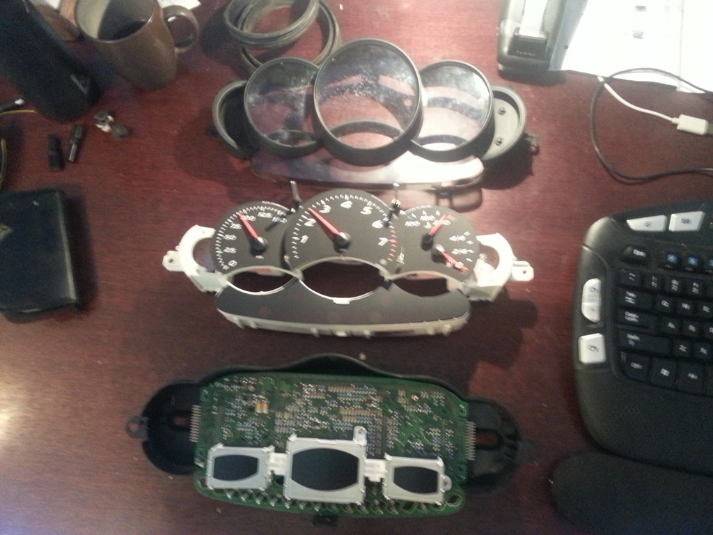
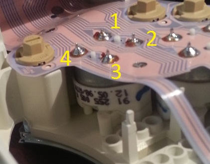
I had some time this afternoon to tear into the gauge cluster and look at it's internals. The first pic shows each piece of the assembly: 1) The lens covers, 2) The air-core motors and gauge lights, and 3) the circuit board driving it all. (Sorry for the blurry pic)
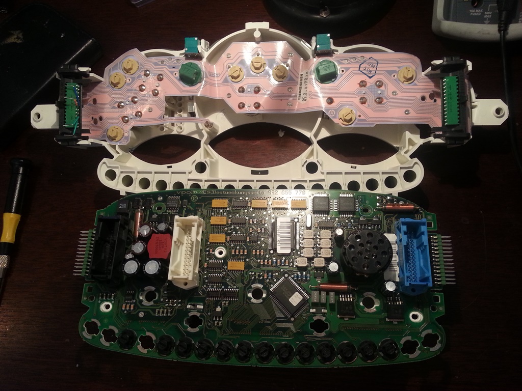
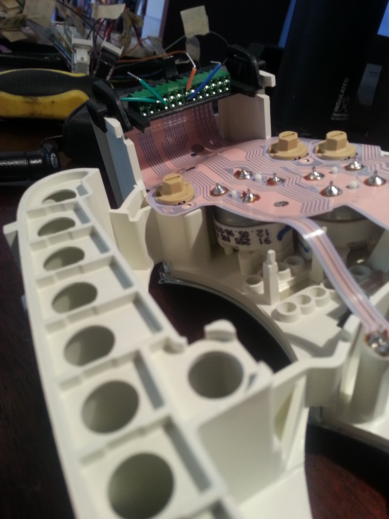
Looking at the connections, it's next to impossible (for me anyways) to try and trace the circuits driving the fuel gauge air-core motor, however; they've made it pretty easy to tap into the circuit through some header pins on the edge of the circuit board. Pics 2 and three show this connection, and I've already traced out which pins go to the two coils on the fuel gauge motor. My next question is: what's the best way to generate this signal? From what I understand it takes two PWM signals shifted by 90 degrees? This is my first time playing with air-core motors.
Posted by: Dr Evil Sep 19 2014, 03:47 PM
Oooooo
I like the splicing into the OE motor method mentioned. I hope it works.
Posted by: timothy_nd28 Sep 19 2014, 04:07 PM
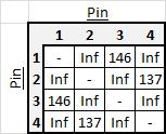
To see how this air core motor is wired internally, we need resistances from each leg to each other leg, a total of 12 numbers, tabulated and identified to which connections are being measured (should be 4 terminals).
Posted by: skeates Sep 19 2014, 04:45 PM
To see how this air core motor is wired internally, we need resistances from each leg to each other leg, a total of 12 numbers, tabulated and identified to which connections are being measured (should be 4 terminals).
Here are the measurements you spoke of (See pic below for pin ID). Looks to me like the coils are:
Coil 1: Pin1 to Pin3
Coil 2: Pin2 to Pin4
Is there any way to figure out which is the Sin coil and which is the Cos?
Posted by: worn Sep 19 2014, 07:13 PM
It would be difficult to defeat the ECU communication for the 1/4-0 tank status. The gas gauge should be a standard air core motor. By opening up the gauge cluster, it would easy to sever the tracks on the circuit board to the air core motor, then wire up the aircore wire directly, like a 1967 Camaro. What do you think?
Looking at the connections, it's next to impossible (for me anyways) to try and trace the circuits driving the fuel gauge air-core motor, however; they've made it pretty easy to tap into the circuit through some header pins on the edge of the circuit board. Pics 2 and three show this connection, and I've already traced out which pins go to the two coils on the fuel gauge motor. My next question is: what's the best way to generate this signal? From what I understand it takes two PWM signals shifted by 90 degrees? This is my first time p
I don't think we are in Kansas anymore. Ohm isn't gonna help me with this one, is he?
Posted by: timothy_nd28 Sep 19 2014, 07:53 PM
Ok. If you reset the board and have the fuel gauge reading full, measure the voltage across 1 (red lead) and 3 (black lead) and then across 2 (red lead) and 4 (black Lead). Then set the fuel level to half full and repeat the measurements. This will tell us max voltage on the coils, which one is sine and which is cosine, and the polarity of the terminals. We then will have all the information required to make the modification.
Posted by: 904svo Sep 19 2014, 08:14 PM
From the reading you have a stepper motor gas gauge, you could try to set your
pot to give a full reading on one set of the windings and another pot with reversed
battery and ground to give a empty reading ( gas gauge sender ).
Posted by: skeates Sep 19 2014, 11:28 PM
Just finished taking some voltage readings on the terminals. Looks like they each oscillate between negative 5 volts and positive 5 volts, but at a very slow rate (probably takes about a full minute to go through a cycle. Seems like I might need an oscilloscope to figure out what this signal is looking like.
Posted by: timothy_nd28 Sep 19 2014, 11:35 PM
Is the needle fixed at full level but the voltages are still changing from -5 to +5 volts?
The voltages should be stable when the needle stops moving.
Posted by: skeates Sep 20 2014, 12:03 AM
Is the needle fixed at full level but the voltages are still changing from -5 to +5 volts?
The voltages should be stable when the needle stops moving.
It's hard to say whether or not the needle was indeed in it's full position since I cannot take the measurements while it is hooked up to the motor (The components get in the way of a measurement since two of the pins are buried on the bottom). I did give it a good chunk of time though to see if it would stabilize. That said - given my (limited) understanding of air-core motors, wouldn't we expect for the voltage to vary? I was under the impression that they expected inputs in the form of current oscillating in sin/cos wave fashion?
Looks like I'm going to have to pick up some parts to build a motor driver tomorrow
Posted by: Dr Evil Sep 20 2014, 08:04 AM
While I dig the scholastic effort in figuring out the step frequency and such, I must wonder if the modification of a stock 914 fuel gauge into the panel would not be loads simpler as you can then use the stock sender, and tank, and..... However, I in no way wish to dissuade you from the path you have chosen as it is very interesting
Is the sweep angle the same or similar between the 914 and boxter units?
Posted by: timothy_nd28 Sep 20 2014, 08:08 AM
No, the voltages do not oscillate as in a motor, but rather each coil generates a magnetic field, and being at 90 degrees of each other, generate a magnetic field at an angle of atan(I coil1/I coil2). So you can achieve deflection of +/-45 degrees with a current level from 0 to max in coil1 (simultaneously changing current in coil2 from max to 0). There is a bar magnet on the needle which aligns with this field, causing the needle to move.
Try to solder wires on the motor pins and re-assemble to run the test and take measurements.
Posted by: Dr Evil Sep 20 2014, 08:15 AM
Fascinating. I have never heard of aircore gauges. More explanation here:
http://en.wikipedia.org/wiki/Air_core_gauge
Pretty cool. I am used to the old school type of single coil.
Posted by: timothy_nd28 Sep 20 2014, 08:57 AM
In my signature, i did a write up on how to do a tach conversion with a air core motor.
Posted by: Dr Evil Sep 20 2014, 11:27 AM
Looked at it, bumped it Good stuff.
Would the stock gas tank sender be able to be made to work with the aircore? Would an interface be needed that would change the signal from the sensor into a signal that they aircore could use?
Posted by: timothy_nd28 Sep 20 2014, 11:48 AM
Absolutely using the original sender, everything will be plug and play after the modification
Posted by: timothy_nd28 Sep 20 2014, 11:49 AM
Absolutely using the original sender, everything will be plug and play after the modification
Posted by: Dr Evil Sep 20 2014, 12:20 PM
Badass!
Posted by: skeates Sep 20 2014, 03:55 PM
While I dig the scholastic effort in figuring out the step frequency and such, I must wonder if the modification of a stock 914 fuel gauge into the panel would not be loads simpler as you can then use the stock sender, and tank, and..... However, I in no way wish to dissuade you from the path you have chosen as it is very interesting
Thanks for the suggestions! I do happen to have my old fuel gauge hanging out in the garage. I've just hesitated to take it apart since it's a perfectly functional stock gauge that someone might want. If my own attempts to build this circuit fail, I'll likely use that as my fall back.
No, the voltages do not oscillate as in a motor, but rather each coil generates a magnetic field, and being at 90 degrees of each other, generate a magnetic field at an angle of atan(I coil1/I coil2). So you can achieve deflection of +/-45 degrees with a current level from 0 to max in coil1 (simultaneously changing current in coil2 from max to 0). There is a bar magnet on the needle which aligns with this field, causing the needle to move.
Try to solder wires on the motor pins and re-assemble to run the test and take measurements.
Interesting. I'll see what I can do about getting some wires soldered on. We just moved and I no longer have a 240V outlet for my soldering iron (was "junk" being thrown away from an INTEL factory overseas). It's perfect for this stuff, but I need to get a power supply or install an outlet for it. In the mean time it looks like I have some reading up to do on driving air-core motors. Thanks for the link!
Should have some progress to report later tonight!
Posted by: timothy_nd28 Sep 20 2014, 04:49 PM
We will help you with the calculations needed for the resistors needed to drive this air core motor with the stock fuel gauge sender, don't worry about that.
Posted by: Dr Evil Sep 20 2014, 05:20 PM
The link on wiki has some suggestions for driver chips, too I have faith that you will be able to get the stuff you have to work. I likely have the guts from a stock fuel gauge if you end up going that route. No need to destroy a good one.
Posted by: skeates Sep 21 2014, 04:09 PM
From the reading you have a stepper motor gas gauge, you could try to set your
pot to give a full reading on one set of the windings and another pot with reversed
battery and ground to give a empty reading ( gas gauge sender ).
Yup! Was banging my head quite a bit yesterday trying to interpret my measurements when I finally decided to challenge the assumption that this was indeed an air-core motor. Switched up the code and tried driving it like a stepper motor....and....success! This explains the transient voltage measurements I was getting while the gauge was moving. I need to play with the code a bit to see if I can get it to step in 1/2 increments since right now it's a pretty rough movement, but here's a video of it sweeping from empty to full:
https://www.youtube.com/watch?v=V8I68EIvCgI
Posted by: stugray Sep 21 2014, 04:36 PM
Great work!
On a slightly related note:
Just today I got my arduino datalogger working.
It can read 8 analog voltage inputs, rpm (from a standard points setup or MSD 12V tach signal), and serial data from an innovate system.
It then logs data to microSD, and outputs it over USB to be displayed by a droid phone.
It also can control one "alarm light" and a shift light.
So with what you have reverse engineered here, you could easily plug that instrument cluster onto my arduino DL and drive all of the interfaces on the cluster while logging data...
hmmm.... 
Posted by: skeates Sep 22 2014, 12:37 AM
The link on wiki has some suggestions for driver chips, too
I have faith that you will be able to get the stuff you have to work. I likely have the guts from a stock fuel gauge if you end up going that route. No need to destroy a good one.Thanks for the encouragement (and the parts)! Not sure anymore if the stock fuel gauge guts can be made to work since it's a stepper motor? I'm sure that there's got to be a pretty snazzy hardware solution to this.
Great work!
On a slightly related note:
Just today I got my arduino datalogger working.
It can read 8 analog voltage inputs, rpm (from a standard points setup or MSD 12V tach signal), and serial data from an innovate system.
It then logs data to microSD, and outputs it over USB to be displayed by a droid phone.
It also can control one "alarm light" and a shift light.
So with what you have reverse engineered here, you could easily plug that instrument cluster onto my arduino DL and drive all of the interfaces on the cluster while logging data...
hmmm....
That sounds way cool - and totally doable! The gauges/motors are all mounted on a separate plastic frame which can be separated very cleanly from the circuit board. The only thing you'll loose are the LCD displays if you chuck the board. That said, the other gauges were really easy to make work without any ECU trickery (just standard signals). The fuel gauge is the only "problem" piece to this whole puzzle. So - you might be better off keeping the Boxster cluster electronics in there and just isolating the pins on the fuel gauge. That way you can keep the digital speedo, clock, and odometer.
And, on that note, I had a breakthrough this evening and now have things worked out to control the fuel level using a potentiometer! The motor itself is still controlled by an arduino which takes as an input the voltage across the potentiometer. Added a rudimentary smoothing function to try and smooth out the signal, but as you can see in the video there are still some bugs in the software. One thing I'd like to figure out is whether or not there is a way to" zero" the motor without bumping it off its bottom stop. I the long run I can live with it, but It would be nice to not have it do a bouncy jig at the bottom of the gauge every time I turn the ignition on. Anyways - concept is there, now comes the fun bit of converting the concept into a practical application.
https://www.youtube.com/watch?v=QfSpp4YkERY
Posted by: CptTripps Sep 22 2014, 07:59 AM
That's just bad ass....
Posted by: timothy_nd28 Sep 22 2014, 11:20 AM
Awesome! Sorry for sending you down a wrong path, it makes perfect sense now
Posted by: Scott S Sep 22 2014, 12:01 PM
Wow. I have never felt dumber. There are some smart folks on this site!
Cool stuff!!

Posted by: skeates Sep 22 2014, 12:05 PM
Awesome! Sorry for sending you down a wrong path, it makes perfect sense now
No worries - all of the feedback was helpful! Even learned a ton about air-core motors in the process. It's great having the support and experience of this community while tackling things that are just a bit (sometimes more than a "bit") over my head!

Posted by: Dr Evil Sep 23 2014, 07:15 AM
Not that it matters now, since you have been experiencing success with your interface using the Arduino, but what I was referring to with the use of the OE gauge guts was to place the guts behind the gauge face in place of the original, put the Boxter needle on the shaft of the OE unit, and then use the original tank sender. I see this as simple, but not nearly as much fun, nor elegant  The problems I foresee doing this are possible length of shaft of OE too short, needle wont work on shaft, sweep ark of OE not same as Boxter and thus gauge face will not be correct measurement/needle deflection will be incorrect, OE guts will not fit.
With your initial start up causing needle bounce, is it possible to have a value programmed in to make the needle hold a value consistent with the E at start up? How bout Full and then is drops to actual? Is this bounce of the needle stop due to poor or no signal? Does the stock setup in a Boxter do this, or is this just due to your interface? How about a delay in the interface that allows it to power up before sending a signal to the gauge so that there is no "seizure" on start up?
Posted by: Philip W. Sep 23 2014, 07:31 AM
Wow. I have never felt dumber. There are some smart folks on this site!
Cool stuff!!
LOL for sure- i was thinking the same thing, now i wish i had taken more electrical classes!! some think "ohm" is what you say when meditating --- i guess my brain has too much "resistance" to learning this type of stuff -
 but i get the big picture, - very interested to how this all pans out!!
Posted by: ruby914 Sep 23 2014, 10:02 AM
Nice work Skeates!
The Boxter cluster up against the OE bezel looks great. The cluster looks nice and small, the biggest problem may be the depth. I don't recall how much room you have to work with, the Boxter looks small but deep.
For the bottom you could trim some off the lower dash sub frame and remove or remake the top loop. I removed my top loop and the cluster mounts to the bottom of the dash.
It seems like, with a custom bezel, it would look great in the OE dash.
What motor is going in this car?
Attached image(s)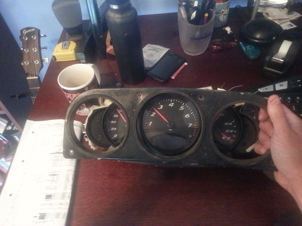
Posted by: skeates Sep 23 2014, 10:57 AM
Not that it matters now, since you have been experiencing success with your interface using the Arduino, but what I was referring to with the use of the OE gauge guts was to place the guts behind the gauge face in place of the original, put the Boxter needle on the shaft of the OE unit, and then use the original tank sender. I see this as simple, but not nearly as much fun, nor elegant
The problems I foresee doing this are possible length of shaft of OE too short, needle wont work on shaft, sweep ark of OE not same as Boxter and thus gauge face will not be correct measurement/needle deflection will be incorrect, OE guts will not fit. With your initial start up causing needle bounce, is it possible to have a value programmed in to make the needle hold a value consistent with the E at start up? How bout Full and then is drops to actual? Is this bounce of the needle stop due to poor or no signal? Does the stock setup in a Boxter do this, or is this just due to your interface? How about a delay in the interface that allows it to power up before sending a signal to the gauge so that there is no "seizure" on start up?
That's a good suggestion as it sidesteps the need to get elbow deep in electronics and coding. Since I followed this route I'm not sure about how well OE motor would fit into the Boxster cluster's frame. It's pretty tight in there and the whole assembly would need to fit neatly sandwiched between the face and the electronics board. If I can get those spare internals from you (and folks are interested), I can mock it up to see how well things fit - I imagine it'll be pretty obvious once one puts them next to each other.
On the needle bounce - from what I gather it's somewhat of an evil necessity for an open loop stepper motor system. I believe that the boxster cluster has some pretty sophisticated electronics that can keep better track of the needle position, but it still has to zero the needle - though it doesn't seem to bounce the way mine does. I think it has to do with the fact that the OEM electronics are able to drive the motor in mircro-steps rather than in the half-steps that I am limited to. Last night I did a bit of research on stepper motor integrated circuits as I'd like to fashion a better hardware solution than what I currently have. If I can get that working it should be pretty easy to reproduce for interested folks. Obviously I would also post all the info hear for anyone wanting to DIY.
Nice work Skeates!
The Boxter cluster up against the OE bezel looks great. The cluster looks nice and small, the biggest problem may be the depth. I don't recall how much room you have to work with, the Boxter looks small but deep.
For the bottom you could trim some off the lower dash sub frame and remove or remake the top loop. I removed my top loop and the cluster mounts to the bottom of the dash.
It seems like, with a custom bezel, it would look great in the OE dash.
What motor is going in this car?
I wish I had my OEM dash cap up here to check the fit of this cluster in the stock dash. I don't think depth will be an issue as it's not that much different than the stock gauges. Plus, the plugs have a much lower profile so one get's a little more room because of that. I think the difficult part is height. The indicator lights on the Boxster cluster stick out just below the OEM mounting face and I think the clearance issue would be with the top of the steering column rather than the dash subframe. But, if there is some wiggle room on top one might just need to build a custom bezel and be done! BTW, the car has a suby EZ36 in it - though I still have to fab exhaust and get it a computer before I can turn it on. http://www.914world.com/bbs2/index.php?showtopic=88085&hl=.
Posted by: Dr Evil Sep 23 2014, 05:52 PM
All of my shit is in boxes in the back of a truck heading to OH. If you decide you want to try my method, I will dig for and send you the guts
Looking forward to more electronic hi jinx
Why not just remove the stop pin for the fuel gauge?
Posted by: Chris914n6 Sep 25 2014, 02:27 AM
Cluster fit doesn't look too far off. The loop will have to be cut off but the top pad will flex a bit. There is room to trim the dash before you hit chassis.
The 914 fuel sender is a pretty common 0-90 ohm. GM standard, and my 90's Nissan cluster work with it, so there are options for a donor motor.
Posted by: purple505uk Oct 26 2015, 02:07 PM
So, until someone tells me this is cluttering up the web I'm going to keep posting my progress
. Made a bit more progress on the boxster gauge cluster this weekend. First things first; even though I'm making a custom dash cap I figured I'd check to see how close this thing fits within the stock set-up. I figured if it fits that would open up a world of opportunities to those wanting to update their gauges, and stick with the Porsche feel without having to make a custom dash. So...I dug out the mounting plate for the stock gauges just to see how close the fit was (see first pic). It's hard to see in the picture, but there are two issues as I can tell which would make it difficult (though not necessarily impossible) to use this with the stock dash cap. 1) The toggles on the top of the cluster (for setting the clock, adjusting brightness, etc.) line up just about perfectly with the two top mounting screw holes. This wouldn't be too hard to work around since you'd be fabricating a custom surround to mount the gauges. At that time just move/make new tabs on the dash frame that line up. Done.
2) The second issue may be somewhat more difficult to work around. Looking at the bottom of the picture you can see that the pod housing the warning lights sticks out slightly below the bottom of the mounting plate. The boxster cluster is just a little bit too tall from what I can tell to fit within the stock dash cap - but it's such a close fit! So close that without an actual dash cap to play with I can't make any final conclusions on the possibility of making this thing fit with the stock dash cap. (if anyone wants to head up to Truckee, Ca with a stock cap to test this out with feel free to swing by
)So, onto the fun stuff - electricity! I've spent more time then I care to think about tracing the boxster wiring diagrams and trying to piece together what's needed and what's not. There are several power inputs, (2) which are constant +12V and (3) more which are powered when the key is in the ACC/Drive position in the ignition. Also, there are (2) grounds for the cluster and an additional "ground" for the sender units (fuel, coolant temp, etc). In order to keep strait the mess of wires I manually pinned out and labeled each wire through the connectors. While doing so I found that many of the expected wires/inputs were "missing" from my pins. Some of these are for inputs from the tiptroic transmission which I expect to be missing on a manual cluster. Others though I think are related to the on-board computer option. At this point I'm just worried about basic functionality, so I'm not paying a whole lot of attention to the missing inputs, but they may become important later if the cluster is expecting an input that I'm not delivering. Note my pig-tails are out of a different '97 manual boxster than the gauge cluster, so there could be some miss-match happening if the options on the cars were different. Below there's a picture of my test-rig (basically just a bread board to facilitate quick & easy circuits and and arduino board that I'm using as a signal generator to simulate speedo and tach signals.
With the gauge cluster powered I then went through at tested the voltage at each (well most anyways) wire to see if any were powered. After doing this I found out something very interesting - most of the indicator lights, the speedo signal, and the tach signal are all powered and expect a ground as their "input". In the case of the speedo and tach they need to be pulled down to ground at a certain frequency, like a flickering light switch, which corresponds to the speed of the car/engine. I'm not sure whether or not this is "normal" for these types of signals, but I was expecting to have to produce a +12V signal to each, not a ground. It actually made it easier in a sense since all I needed to do was use a general purpose transistor as a switch and feed it a PWM signal from the arduino. I addition to those signals, I also got some potentiometers out to simulate the coolant temp and fuel senders. The pic below shows everything running...sort of...
So, the moral of this story is that I've been able to get all the basic functionality working! I've got an Excel spreadsheet I use to calculate at what frequency the PWM signal needs to operate to simulate a specific MPH or RPM. I've also got the coolant temp gauge sender resistance values figured out, the gauge back-lighting/dimming is working, indicator lights are all functional, as well as the turn-signals/high beam indicators, etc.. But....and so far it's been a big pain in the butt....the damn fuel gauge is only sort-of working and represents the final piece to this puzzle.
The top 3/4 of the fuel gauge range works flawlessly with a 0 - 400 Ohm potentiomter. However, as soon as you get to ~ 400 Ohms (just less than 1/4 tank) the fuel gauge drops to empty and the low fuel indicator light starts flashing. Doing some reading I found that on the 996 C4's the gas tanks were designed such that a sender wouldn't fit all the way down and then the gauge had to switch over to some sort of internal calculation approach using fuel consumption data from the ECU to estimate fuel tank levels below 12 litres. I didn't get the sense though that this was true of the C2's or the Boxters. Something definitely happens at the 1/4 tank mark where the gauge stops listening to the sender signal. In fact, once it hits that mark I can no longer get the needle to move at all by changing the resistance values. I have to do a full reset on the cluster (un-plug and plug back in) to get it to listen again. I figure it has to be looking for a signal that I'm not giving it right now, and I think I've isolated it to one or two wires:
1) There is a fuel tank status wire going to the DME (ECU) which I thought was an output, but now I'm wondering if it's an input. It has no voltage when the cluster is powered.
2) There is a wire labeled "KVA DME" on the cluster diagrams, but on the DME wiring diagram it's labeled "fuel consumption indicator". I think this one may be the missing piece, but I have no idea what signal it's sending. On the cluster this wire measures +10 V (same as the speedo and tach wires) which makes me think its looking for a similar signal to ground. My current guess it that it will somehow correspond to the fuel injector pulse signal.
If anyone has any ideas (or information) on how to get the last quarter of the fuel gauge working I'd LOVE the input. It's the last 10% that takes 90% of the time/effort!
Great work! Im not the best at electronics and need to power up the lower lcd screens on the same 986 dash can you tell me what voltage i need 12v DC or Ac? , and which colour plugs and which pins do I need to supply this voltage too? Also which ones do i need to ground? Ive tried to work it out from you pic , I cannot tell very well from there, your help is massively appreciated sorry to be a noob!!
Powered by Invision Power Board (http://www.invisionboard.com)
© Invision Power Services (http://www.invisionpower.com)