Printable Version of Topic
Click here to view this topic in its original format
914World.com _ 914World Garage _ Turn signal switch
Posted by: HalfMoon Aug 4 2014, 09:44 PM
How do we statically test (ohn meter or continuity tester) a column turn signal switch un-installed?
TY
David
Posted by: Mike Bellis Aug 4 2014, 10:03 PM
3 wires
Black w/green & white stripe (common)
Black w/ green stripe
Black w/ white stripe
Test continuity between the common to one of the other two while the switch is turned.
EDIT: you may have to disconnect all three from the circuit to get an accurate reading.
Posted by: HalfMoon Aug 4 2014, 10:17 PM

3 wires
Black w/green & white stripe (common)
Black w/ green stripe
Black w/ white stripe
Test continuity between the common to one of the other two while the switch is turned.
EDIT: you may have to disconnect all three from the circuit to get an accurate reading.
Great stuff! I have continuity on those pins

Do you happen to know whitch pin should have continuity when tested against common for the high beam?
Posted by: Mike Bellis Aug 4 2014, 10:32 PM
3 wires
Black w/green & white stripe (common)
Black w/ green stripe
Black w/ white stripe
Test continuity between the common to one of the other two while the switch is turned.
EDIT: you may have to disconnect all three from the circuit to get an accurate reading.
Great stuff! I have continuity on those pins
Do you happen to know whitch pin should have continuity when tested against common for the high beam?
High beam does not go through the turn signal switch. There is a brown/white or brown/yellow from the switch that is a momentary ground when the switch is pulled. This ground triggers the relay which is electro-mechnaical. There is a toggle cam inside that is designed to switch directions each time the switch is pulled. There is a spring that can wear and prevent the Hi/Lo relay from working correctly.
Posted by: HalfMoon Aug 4 2014, 10:37 PM
3 wires
Black w/green & white stripe (common)
Black w/ green stripe
Black w/ white stripe
Test continuity between the common to one of the other two while the switch is turned.
EDIT: you may have to disconnect all three from the circuit to get an accurate reading.
Great stuff! I have continuity on those pins
Do you happen to know whitch pin should have continuity when tested against common for the high beam?
High beam does not go through the turn signal switch. There is a brown/white or brown/yellow from the switch that is a momentary ground when the switch is pulled. This ground triggers the relay which is electro-mechnaical. There is a toggle cam inside that is designed to switch directions each time the switch is pulled. There is a spring that can wear and prevent the Hi/Lo relay from working correctly.
Hmmm. Would that mean I could test using my continuity tester by attaching to the common then either the brown/white or brown/yellow and make my test light go on and off using the pull function of the switch? Would that not test the circuit?
Posted by: Mike Bellis Aug 4 2014, 10:44 PM
3 wires
Black w/green & white stripe (common)
Black w/ green stripe
Black w/ white stripe
Test continuity between the common to one of the other two while the switch is turned.
EDIT: you may have to disconnect all three from the circuit to get an accurate reading.
Great stuff! I have continuity on those pins
Do you happen to know whitch pin should have continuity when tested against common for the high beam?
High beam does not go through the turn signal switch. There is a brown/white or brown/yellow from the switch that is a momentary ground when the switch is pulled. This ground triggers the relay which is electro-mechnaical. There is a toggle cam inside that is designed to switch directions each time the switch is pulled. There is a spring that can wear and prevent the Hi/Lo relay from working correctly.
Hmmm. Would that mean I could test using my continuity tester by attaching to the common then either the brown/white or brown/yellow and make my test light go on and off using the pull function of the switch? Would that not test the circuit?
If it is working correctly, clip the test light to the brown striped wire and the tip of the light on a power source. Pull the switch and the test light should illuminate.
Posted by: HalfMoon Aug 4 2014, 11:02 PM
3 wires
Black w/green & white stripe (common)
Black w/ green stripe
Black w/ white stripe
Test continuity between the common to one of the other two while the switch is turned.
EDIT: you may have to disconnect all three from the circuit to get an accurate reading.
Great stuff! I have continuity on those pins
Do you happen to know whitch pin should have continuity when tested against common for the high beam?
High beam does not go through the turn signal switch. There is a brown/white or brown/yellow from the switch that is a momentary ground when the switch is pulled. This ground triggers the relay which is electro-mechnaical. There is a toggle cam inside that is designed to switch directions each time the switch is pulled. There is a spring that can wear and prevent the Hi/Lo relay from working correctly.
Hmmm. Would that mean I could test using my continuity tester by attaching to the common then either the brown/white or brown/yellow and make my test light go on and off using the pull function of the switch? Would that not test the circuit?
If it is working correctly, clip the test light to the brown striped wire and the tip of the light on a power source. Pull the switch and the test light should illuminate.
I tried that test but no love

However, when I use a continuity tester between brwn/wht and brwn/blue (pin 1 and 2), I can get continuity when I activate the switch....
Posted by: HalfMoon Aug 5 2014, 10:21 AM
Took my old switch out this morning and it tested ok.
Is there a test for the hazard circuit that I'm missing?
TY
David
Posted by: Mike Bellis Aug 5 2014, 07:43 PM
Someone on this site provided this. Please take credit!
This is a great drawing that shows the entire circuit. Trace out all these wires and check your lamps. Make sure you have European dual element lamps where needed and not the US ones.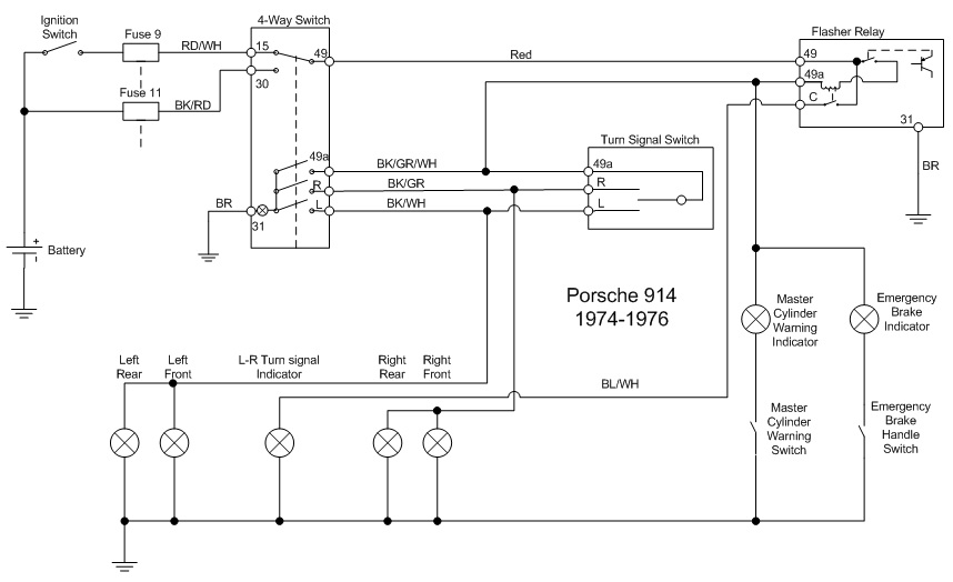
Posted by: HalfMoon Aug 5 2014, 08:17 PM
Someone on this site provided this. Please take credit!
This is a great drawing that shows the entire circuit. Trace out all these wires and check your lamps. Make sure you have European dual element lamps where needed and not the US ones.
Awesome find Mike!
I see fuse 9 and 11 are involved. Can't help wonder if the rotation of fuse trick like what we did to solve the right side highbeam problem might get em working again? Seems pretty easy to try, right?
As an aside, they were working before I replaced all my fuses (and yes I emory clothed everything), so mebbe, eh?
Any other suggestions?
Thanks again!
David
Posted by: HalfMoon Aug 6 2014, 02:06 PM
Mike!
You win the prize again!
The diagram showed me what to look for and I've solved the problem. Flashers now work!
Powered by Invision Power Board (http://www.invisionboard.com)
© Invision Power Services (http://www.invisionpower.com)