Printable Version of Topic
Click here to view this topic in its original format
914World.com _ 914World Garage _ Problem with wiring from Relay Board to Coil etc.
Posted by: 91422.7 Apr 6 2015, 12:15 PM
Something isn't adding up! I have a 1970 Porsche 914 which I've upgraded with a 2.0L engine out of a 1975 914 along with the 1975 Ignition Wiring Harness. The engine has had the distributor upgraded to an electronic ignition from the original points setup. The two wires coming from the bottom of the distributor (Red goes to Positive terminal on Coil) and (Black goes to negative on Coil). Reference attached picture or diagram I've drawn of the Engine Relay Board, right rear plug in on board! With key on, I'm getting 2 hot wires from the terminals, (One) is the 4th Pin down on left (Solid Black Wire) and the other is the top right pin (Grey with Red Stripe)! The other wires/pins are not hot! Green/Red, Black/Purple, Green Jumper Wire, 2nd Grey/Red Wire, Large Yellow Wire, Black/Red Wire. From diagrams I've pulled from on line, it appears the following wires should go to the following locations from the Engine Relay Board/plug in above mentioned:
* Black/Red Wire goes to (+) Positive on Coil
* Black/Purple Wire (Tach Signal Wire) goes to (-) Negative on Coil
* Large Yellow Wire goes to Starter
* Small Yellow Wire goes to ?
* Green/Red Wire goes to Oil Pressure/Sending Unit next to Distributor
* Solid Black Wire goes ?
* 2 Grey/Red wires go to sending unit on side of transmission
......My question is why are those two wires hot (Solid Black Wire and the One Grey/Red Stripe Wire)?
......Shouldn't instead the Black/Red Wire should be the hot one going to the Coil?
......OR is the problem I have the wrong Wiring Harness and if thats the case why cain't I just change the pin locations on the plug in on the relay?
...Thanks for any help!
Attached image(s)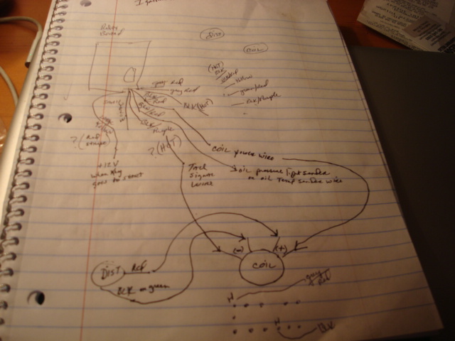
Posted by: SirAndy Apr 6 2015, 12:28 PM
The '70 relay board is different than the '75 relay board. I think the change happened in '73?
Anyways, the connector for the engine harness on the relay board needs to have some wires shuffled since the layout there has changed.
Pelican Parts has color diagrams of both relay board types showing the differences in the pin layout.
http://www.pelicanparts.com/914/914_electrical_diagrams.htm
Early: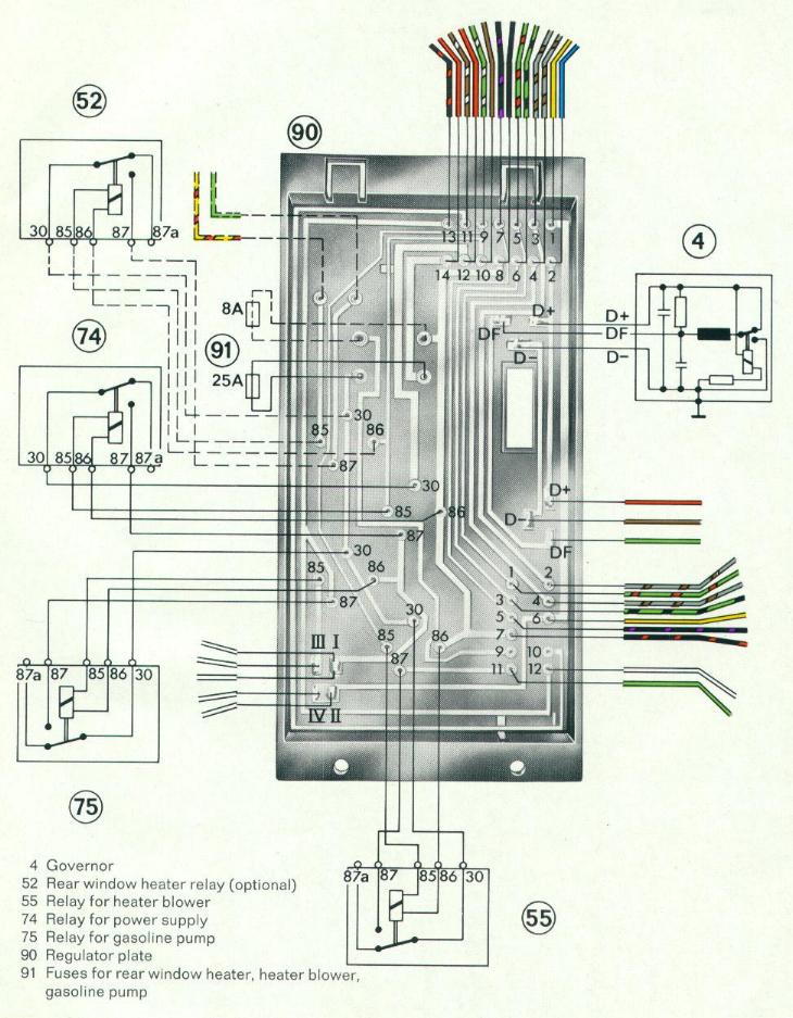
Late: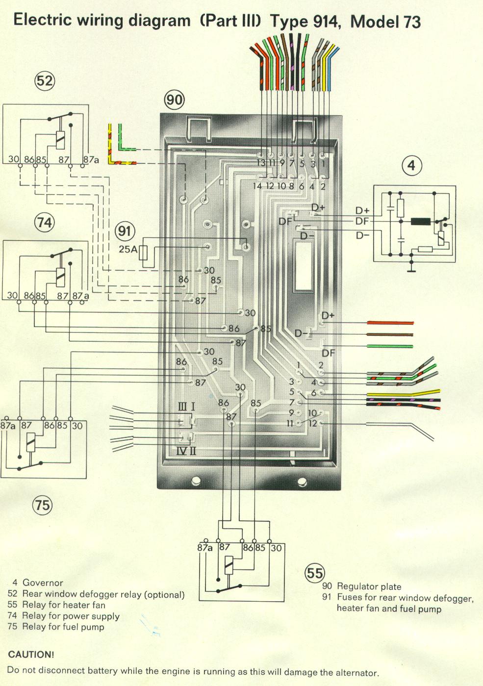

Posted by: 91422.7 Apr 6 2015, 08:43 PM
I changed the wiring pins up in the 12 pin plug on the relay board as follows:
* 1 = green/red
* 2 = grey/red
* 3 = blank
* 4 = grey/red
* 5 = blk/purple
* 6 = yellow
* 7 = blk/red
* 11/10 = jumper wire green
On the Coil:
* I have on the Positive terminal N15: Blk/Red (Hot)
Red Wire from Distributor (Electronic)
* I have on the Negative terminal N1: Black/Purple (Tach)
Black wire from Coil
.....As soon as I hook the Blk/Red Wire to N15 all terminals (+ and -) post go hot! Why?
...Have I got the Coil wired wrong? Thanks
Posted by: worn Apr 6 2015, 08:59 PM

I changed the wiring pins up in the 12 pin plug on the relay board as follows:
* 1 = green/red
* 2 = grey/red
* 3 = blank
* 4 = grey/red
* 5 = blk/purple
* 6 = yellow
* 7 = blk/red
* 11/10 = jumper wire green
On the Coil:
* I have on the Positive terminal N15: Blk/Red (Hot)
Red Wire from Distributor (Electronic)
* I have on the Negative terminal N1: Black/Purple (Tach)
Black wire from Coil
.....As soon as I hook the Blk/Red Wire to N15 all terminals (+ and -) post go hot! Why?
...Have I got the Coil wired wrong? Thanks
What do you mean by all terminals? If i understand correctly the minus lead from the coil will not be minus until either grounded by the points or the electronics. Ime the electronics are harder to sus out unless the engine is running and then they are impossible. But then i am easily confused. Still i might expect the reading of the minus side of the coil primary to vary from 12v to ground, depending on the situation. Forgive me if i have found a grove of wrong tres to bark at.
Posted by: Jeff Bowlsby Apr 6 2015, 09:02 PM
A couple of things:
914/4 relay boards are all identical, they did not change year to year...the wiring connections changed from the chassis harnesses and ignition harnesses, but the relay boards are not changed. 914;6 relay boards are different from the 914/4 relay boards.
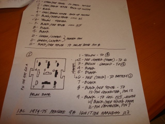
What you refer to as Grey/red is Grey brown, they are for the transaxle mounted rear back-up lights. One wire should be hot, the circuit just completes though the switch.
What y9ou think is solid black is actually black/red, the red is just very light, dirty or worn off. It connects with pin 7 of the 12 pin connector.
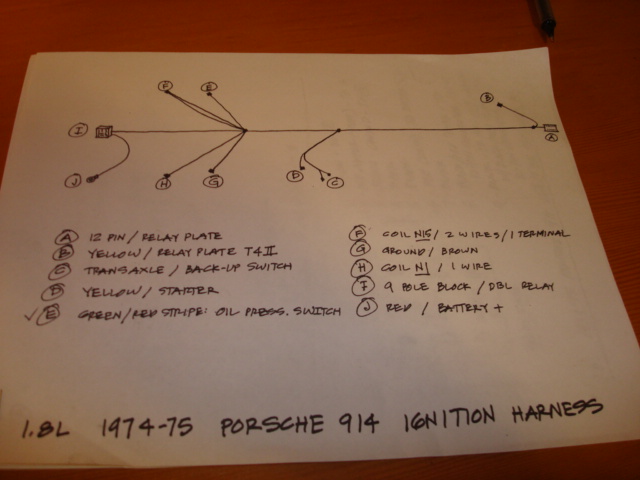
You have an LJet ignition harness diagram...that's not correct for a 2.0L. Do you have the 1.8L FI system mounted to the engine also? DJet and LJet hardware and harnesses are not interchangeable.
Posted by: 91422.7 Apr 6 2015, 09:07 PM
I have a Fuel Injection System off of a 1975 914 2.0L.
Posted by: 91422.7 Apr 6 2015, 09:13 PM
When I mentioned All Terminals, I was referring to the 4 terminals on the coil, 2 (-) and 2 (+).
Posted by: worn Apr 6 2015, 09:26 PM
When I mentioned All Terminals, I was referring to the 4 terminals on the coil, 2 (-) and 2 (+).
Could it not be that the e ignition has not decided to ground and collapse the magnetic field at the time you made the measurement? Just askin here.
Posted by: SirAndy Apr 6 2015, 09:31 PM
There are some small differences over the years but you are correct, the boards have the same tracing for all /4 models and by itself are interchangeable.
The differences are in what wires connect to what pins on both of the large connectors.
Also note that the 85/86 pins for all relays are flipped between early and late cars.

Posted by: 91422.7 Apr 6 2015, 09:31 PM
When I mentioned All Terminals, I was referring to the 4 terminals on the coil, 2 (-) and 2 (+).
Could it not be that the e ignition has not decided to ground and collapse the magnetic field at the time you made the measurement? Just askin here.
...That's possible! I don't believe I mentioned earlier but I also have no spark out of the plug wires!
Posted by: Jeff Bowlsby Apr 6 2015, 09:34 PM
I have a Fuel Injection System off of a 1975 914 2.0L.
Then why are your referencing a 1.8L ignition harness diagram? The 1.8L and 2.0L Fi systems and components are not compatible.
Posted by: 91422.7 Apr 6 2015, 09:37 PM
Ok, assuming I have the wrong Ignition Harness on the 12 pin connector, all one would need to do is change up the location of the Pins to match the FI System your using, etc? If that's is correct, that's what I did as described above. Based on what you guys have said, what would you suggest I do to make it correct on the connections both at the 12 pin connection and the Coil. Thanks again for all your help.
Posted by: 91422.7 Apr 6 2015, 09:40 PM
....That was a mistake on my part, shouldn't of been referencing a 1.8L ignition harness diagram! Sorry
Posted by: Jeff Bowlsby Apr 6 2015, 09:55 PM
You can modify the 1.8L LJet ignition harness to be similar to the 2.0L harness. Compare the diagrams of the two off my harness website and you can figure it out.
You will need a 2.0L FI harness as well, a 1.8L FI harness will not work with the D-Jet hardware.
Posted by: 91422.7 Apr 6 2015, 10:13 PM
...Ok Jeff, thanks again, I will work on it!
Posted by: Tom Apr 7 2015, 01:41 PM
When you are taking voltmeter readings at the coil, they will all be 12 volts unless the points or electronic module is grounding the negative side. This assumes that the coil and wiring, etc. are all good.
If you are not getting spark, place the meter on the negative side, you should be able to see 12v, then ground, then 12v, as you slowly turn over the engine. If this doesn't happen and you have an electronic module ( and it does sound if you have one from the color of wires hooked up to the coil), then you have a bad electronic module. Remember, some of these do not like the key switch left to ON for very long without the engine running.
Tom
Powered by Invision Power Board (http://www.invisionboard.com)
© Invision Power Services (http://www.invisionpower.com)