Printable Version of Topic
Click here to view this topic in its original format
914World.com _ 914World Garage _ 914-6 engine harness questions
Posted by: vintage914racer May 21 2015, 06:57 PM
I'm finally getting the engine back into my 914-6 after a couple years off of the road and there are a few wires that I can't determine where they go.
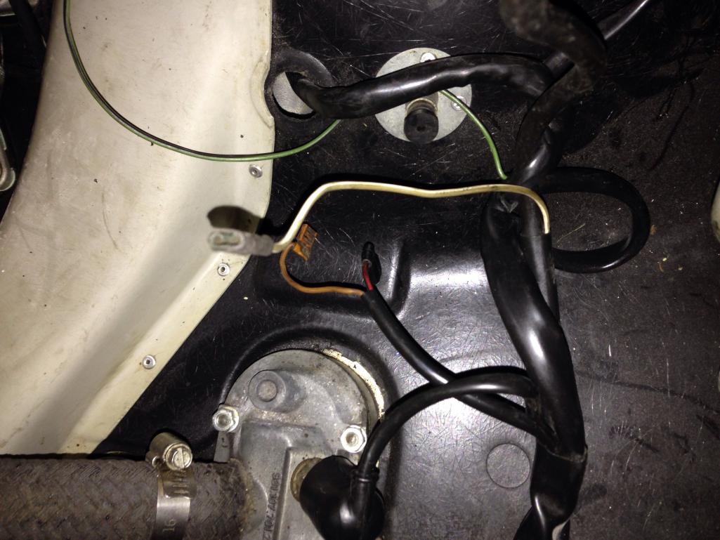
In the first photo one wite is brown and the other is red and black. The wire in the second photo is white and what looks like light green. 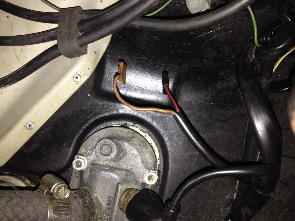
Posted by: johnhora May 21 2015, 09:41 PM
I can't remember the colors....but the cold start valve and the over run dash pot connection wires are some of the ones usually loose and laying around when those two have been removed or are missing
Posted by: johnhora May 21 2015, 09:51 PM
yep...red and brown for the dash pot....see pic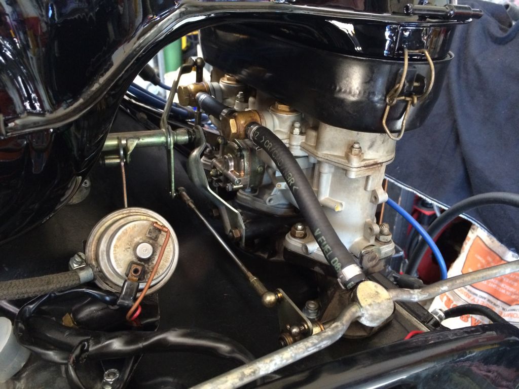
Posted by: johnhora May 21 2015, 09:55 PM
if the green is a long one...it's for the temp sender below the right of the fan....at the oil line....
Posted by: vintage914racer May 21 2015, 10:06 PM

if the green is a long one...it's for the temp sender below the right of the fan....at the oil line....
This is a different green one. I have the long green one hooked up to the temp sender. After tinkering around a bit I realized the white and light green one in the second picture is coming out of part of the harness that connects to te positive battery terminal.
Posted by: johnhora May 22 2015, 09:02 AM
does it have +12v battery on it....if battery connected
Posted by: vintage914racer May 22 2015, 11:50 AM
does it have +12v battery on it....if battery connected
It has a 12v battery.
Posted by: 6freak May 22 2015, 12:24 PM
I can't remember the colors....but the cold start valve and the over run dash pot connection wires are some of the ones usually loose and laying around when those two have been removed or are missing
....correct ..part of the cold start system...remember no choke on the webers...the long one is temp sensor
MikeC
Posted by: johnhora May 22 2015, 03:58 PM
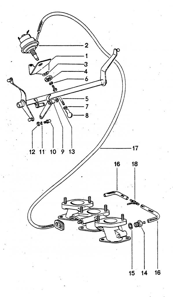
here is a diagram of the parts...
these were early basic "smog gear" used on the 914-6 and 911T with webers of the same period
the diaphragm part #2 kept the throttle WOT open during deceleration to add more air to the fuel mixture for leaner burn(= less pollution)....vacuum to activate it was pulled from the two lines #16 on the intake manifold.....then a relay(pn 901.615.113.00 RPM transducer)on the fuse/relay panel in the engine compartment provided RPM signal to release....
Posted by: johnhora May 22 2015, 04:09 PM
the big problem with this set up is the relay usually goes bad over time and are NLA....
when they fail the engine will backfire during over run (decel)....that's why most of this stuff was disconnected or removed many years ago on most 914-6 and 911T...
you don't need it connected to have the car run properly....
Posted by: vintage914racer May 22 2015, 08:38 PM
Thanks all for the help. The diaphragm was removed from my car long ago because I e never seen it. Therefore it makes sense that the wires are there with nothing to connect to.
With a little luck I should have the car back on the road by the end of the weekend.
Posted by: 6freak May 23 2015, 12:47 PM
cover them and tuck them away....DONT cut them off
Posted by: johnhora May 23 2015, 02:58 PM
cover them and tuck them away....DONT cut them off

Posted by: rgalla9146 May 23 2015, 06:46 PM
The third wire (white / green or is it green / white ?) is for the cold start enrichment valve.
There was a 'manifold' in the original air filter housings.
An electrically controlled valve in the fuel line opened on cold star and fed fuel directly down the carburetor throats.
It was the cause of many a carb fires.
Most often this assembly is missing.
Mine is there, but not plumbed for fuel. Or connected electrically.
Attached thumbnail(s)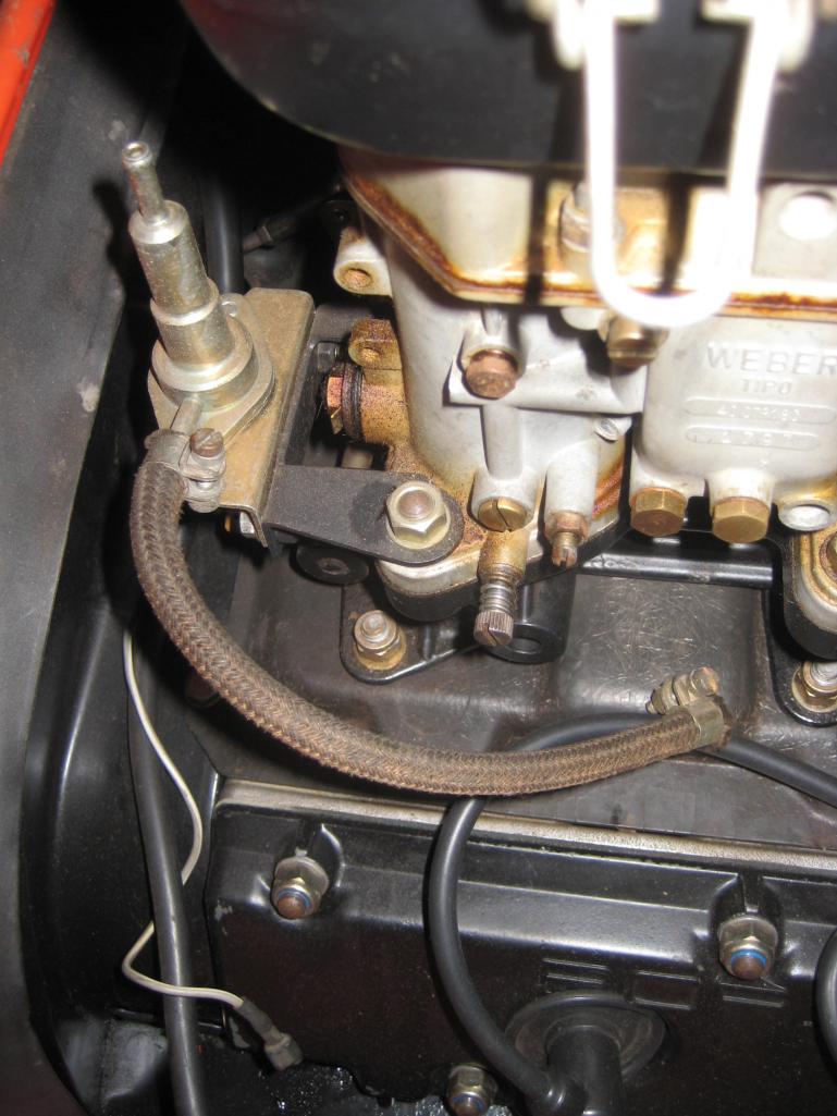
Posted by: 6freak May 23 2015, 08:23 PM
That`s what that is! SOB glad I didnt pitch it while sorting parts the other day

Posted by: rgalla9146 May 24 2015, 07:16 AM
That`s what that is! SOB glad I didnt pitch it while sorting parts the other day
Keep your eyes open for a small white plastic ' T' for fuel delivery to this valve.
It could be in your boxes.
For a complete restoration this part is very difficult to find.
Always discarded or broken.
Posted by: rgalla9146 May 24 2015, 08:37 AM
here is a diagram of the parts...
these were early basic "smog gear" used on the 914-6 and 911T with webers of the same period
the diaphragm part #2 kept the throttle WOT open during deceleration to add more air to the fuel mixture for leaner burn(= less pollution)....vacuum to activate it was pulled from the two lines #16 on the intake manifold.....then a relay(pn 901.615.113.00 RPM transducer)on the fuse/relay panel in the engine compartment provided RPM signal to release....
Not too sure about WOT , more like controlled return to closed throttle.
Posted by: Perry Kiehl Clone May 24 2015, 10:21 AM
It was an idle pull down system. It has a RPM transducer that senses engine RPM, and when it drops below the specific engine speed the transducer tells the dashpot to pull the linkage to the idle position.
FWIW this system in the 914-6 engine relay board allowed easy conversion to MFI. The 914-6 RPM transducer is recommended for retro-fitting in the MFI cars in a Porsche TSB
Powered by Invision Power Board (http://www.invisionboard.com)
© Invision Power Services (http://www.invisionpower.com)