Printable Version of Topic
Click here to view this topic in its original format
914World.com _ 914World Garage _ BUILD-OFF CHALLENGE: Eisberg rustoration
Posted by: mbseto Aug 16 2015, 07:32 PM
Funny, I am as nervous starting this thread as I was to start cutting into my car.
I resolved to start a rustoration thread when I made my first cuts, so here it is. I'm hoping the community will pipe in periodically with any, "Don't do that!", "Do it this other way!", "Do this first!", or "Don't forget this!" comments that are appropriate. Any and all guidance will be appreciated.
So here's the car as I got it, not quite a year ago: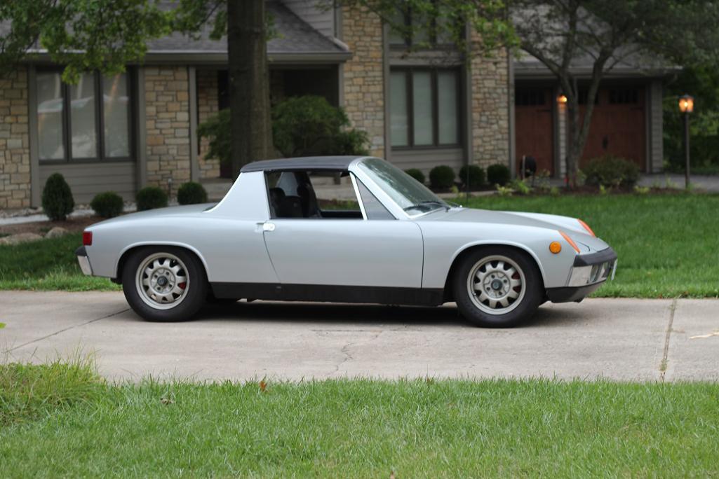
Started out doing a little engine work to get it running, then drove it around a little bit before starting to take it apart. Took the engine out, put it up on a dolly, took out much of the interior and suspension, and this is how it sits now: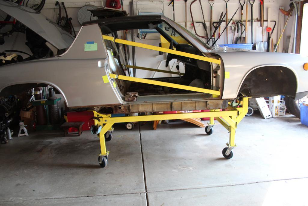
After cleaning out the inside and seeing the rust, it was hard to believe we were driving it at all. These are the first cuts, just straightening out the edges of the rust holes really.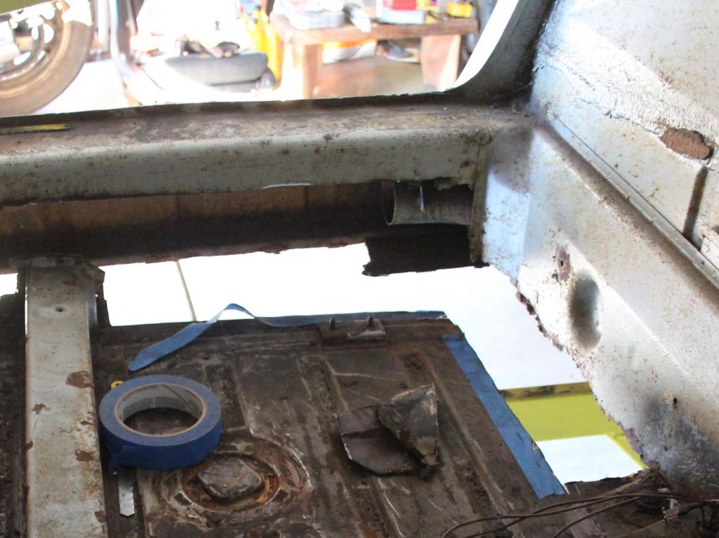
More pics coming soon, I'll be documenting the extent of the damage and forming a battle plan.
Posted by: TargaToy Aug 16 2015, 07:35 PM
Love your dolly setup. Keep the progress reports coming. I'll look forward to following your repairs.
Amazing how much bad crud can lurk below an otherwise really pretty paint job, eh?
Posted by: rick 918-S Aug 16 2015, 08:44 PM
Good bracing. If you end up needing to weld higher than you can reach on the longitudinal I would suggest cutting the door jamb like this. I often see guys cut off the lower quarter panel. I personally don't care to do it that way and don't think it is necessary.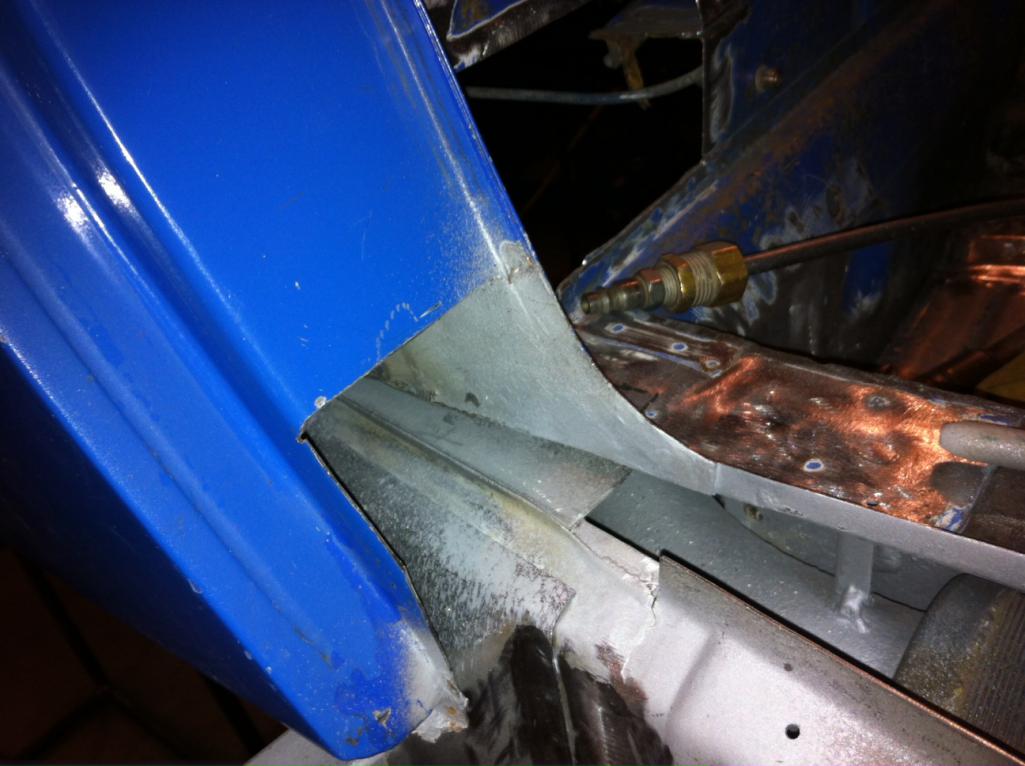
Posted by: mgp4591 Aug 16 2015, 09:01 PM
Thanks for posting your pics- now I don't feel that bad about my rust situation! How's your center tunnel- is it rusted up the sides an inch or two? That's the only piece I could find that RD doesn't sell as their inventory is excellent ... has anyone seen those for sale on any vendor site?
Posted by: Zimms Aug 17 2015, 02:46 AM

Love your dolly setup.
 Nice work
Posted by: thieuster Aug 17 2015, 04:27 AM
Nice! Don't be tempted to start working on the engine too soon. A restored engine sitting idle in the corner of the workshop for a long period will start deteriorating.
BTW, I love the wheels on your car. What are these?
Menno
Posted by: rgalla9146 Aug 17 2015, 08:32 AM
Nice! Don't be tempted to start working on the engine too soon. A restored engine sitting idle in the corner of the workshop for a long period will start deteriorating.
BTW, I love the wheels on your car. What are these?
Menno
VW Super Beetle .... '78-'79 ?
Posted by: Claus Graf Aug 17 2015, 09:03 AM
Nice dolly. Good Luck with the 914!
I would support the front and rear end by adding more beams to the dolly (and maybe a couple of casters).
I would work on one side at a time while leaving the door installed (on the side you're not working).
Regards
Claus
Posted by: blackmoon Aug 17 2015, 09:17 AM
nice work, good luck with the restoration, it's all about the journey
Posted by: jmitro Aug 17 2015, 09:50 AM
love that color.
good luck with your rustoration; I'm just a few hours of work behind you. Removing the engine this week, then start cutting out the rusty parts
Posted by: sfrenck Aug 17 2015, 09:58 AM
Shouldn't the door braces form an "X" or a "Z"?
Not saying that the car is going to move since it's bolted to that beefy support frame, but I don't see how a "four-bar brace" keeps the jambs fixed relative to each other (think sagging fence gate without the diagonal brace).
Posted by: rdauenhauer Aug 17 2015, 10:24 AM
 I do.
I do. 
Posted by: mbseto Aug 17 2015, 06:28 PM
Thanks all for the kind words.
...I would suggest cutting the door jamb like this. I often see guys cut off the lower quarter panel. I personally don't care to do it that way and don't think it is necessary.
Rick;
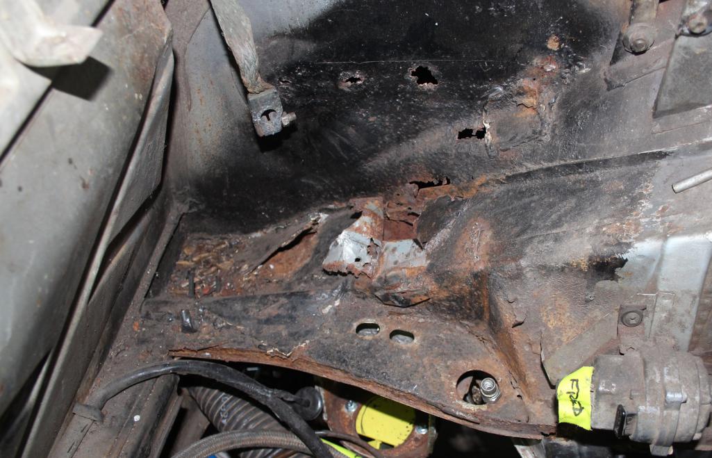
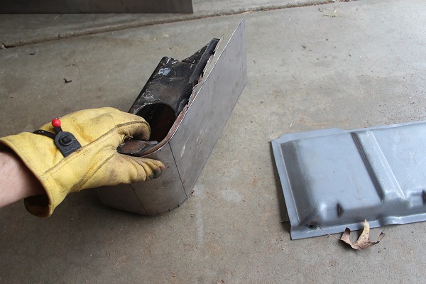
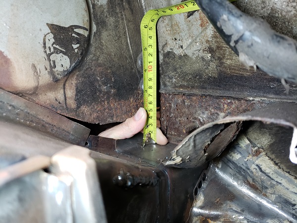
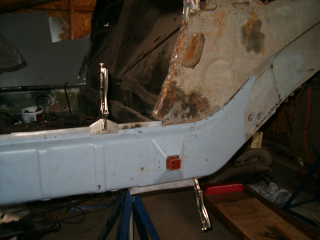
I was hoping to get away with something like that. But the suspension pylon needs to be removed, and so far as I've seen in searching this site, I'll have to cut the quarter panel. Please correct me if I'm wrong on this because I would really rather not. But look at this:
When I poked at this, the hole just kept getting bigger and bigger. Rust and sunflower hulls were pouring out of it. Got a whole bag full.
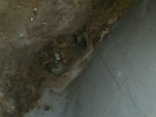
While the outer pylon seems solid, the metal of the long around it is cheese. Cut the long open and this is looking aft and up, inside the long from just aft of the jack point (it looks backwards because it's looking in a mirror). You can see the entrance to the wee beastie's nest.
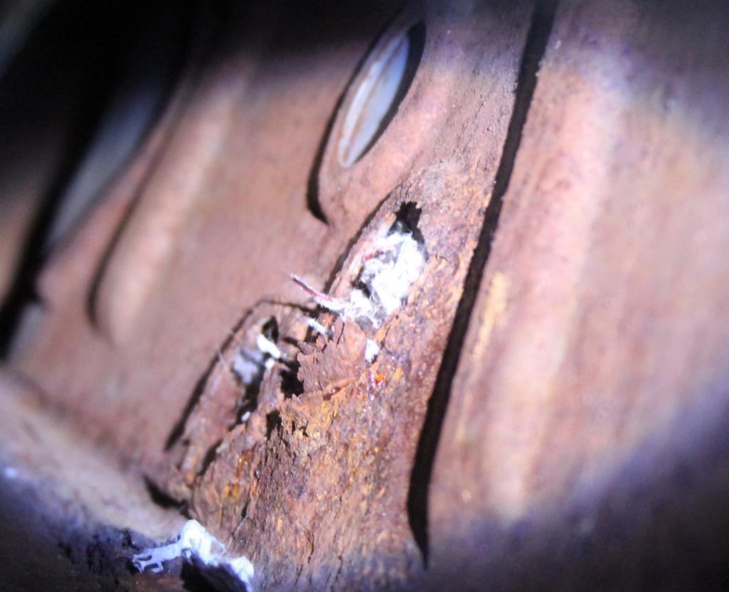
I'm betting his little skeleton might still be inside the pylon.
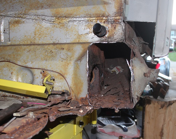
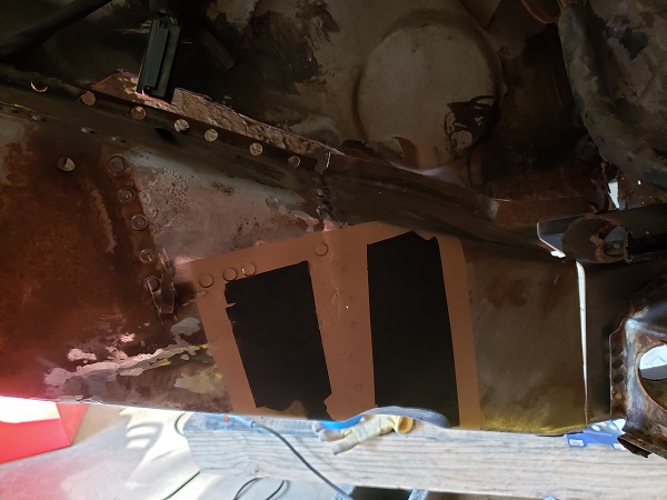
Just for good measure, here's a top down view of my properly hellish hell hole:
Posted by: mbseto Aug 17 2015, 06:34 PM
BTW, I love the wheels on your car. What are these?
VW Super Beetle .... '78-'79 ?
Lemmerz Baja Champion, and yes- Super Beetle, but I think only available in '72-'73? They've really grown on me, but they are narrow. Car's going to be a drifter whether I want to or not.
Posted by: mbseto Aug 17 2015, 06:44 PM
Shouldn't the door braces form an "X" or a "Z"?
Not saying that the car is going to move since it's bolted to that beefy support frame, but I don't see how a "four-bar brace" keeps the jambs fixed relative to each other (think sagging fence gate without the diagonal brace).
I intended the dolly and the braces to all work together- they will all remain attached so far as possible. Both braces on each side are adjustable to set door gaps.
The plan is to measure frequently and if anything sags during the cutting, I will add bracing before welding.
Posted by: DirtyCossack Aug 17 2015, 08:29 PM
I'll be learning in the near future whether you can replace the inner suspension console without cutting the fender (out with the old and the inner long this coming weekend), but in my prep for the job I have assessed that cutting the outer wheelhouse any higher than the outer suspension console would require cutting the fender. I thanked God when I realized that mine was somehow only rusted on the inner side and down low in the curve.
Posted by: mbseto Oct 3 2015, 07:49 PM
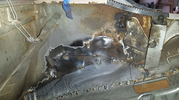
Guess I better update you guys... Some PO welded in some random patches, have to dig them out and find out where the original metal starts. This is the underside of the hell hole: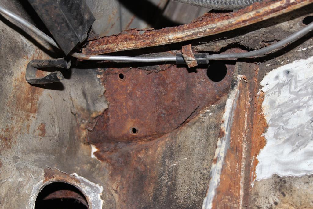
And from above... Looks like grandma's quilt: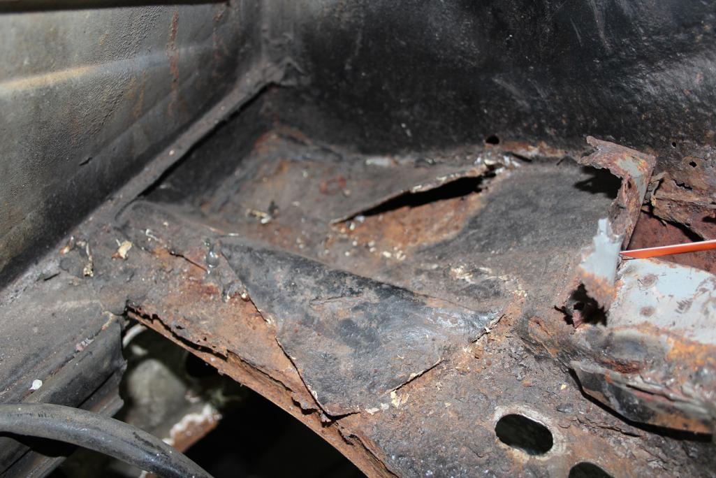
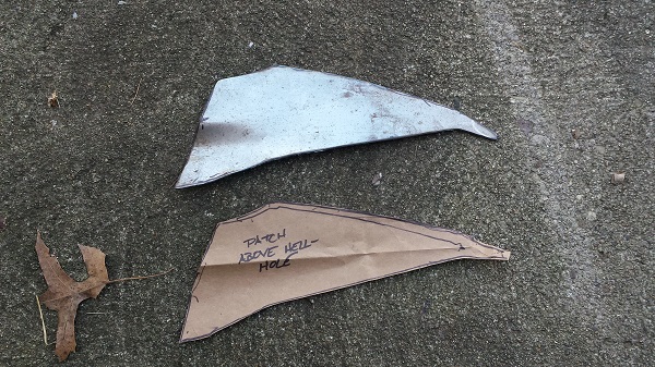
Pulled it all out. This is the PO's "hell hole repair kit"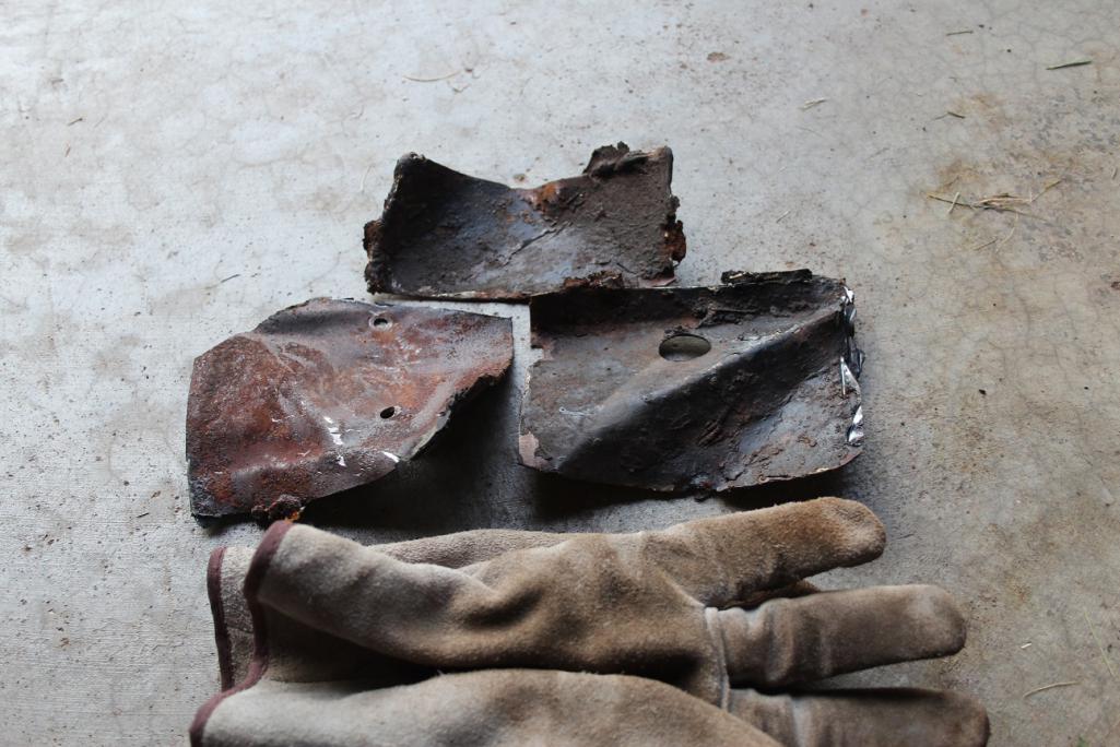
Posted by: mbseto Oct 3 2015, 07:57 PM
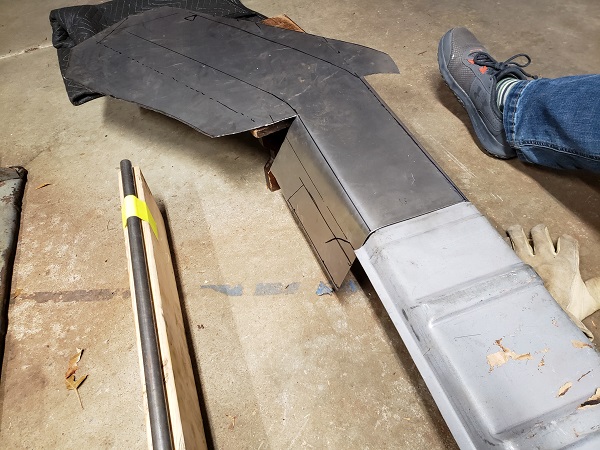
I'm planning on buying a bunch of sheet metal from RD. But to help stay within budget, I made a bending brake- this will be the source of my new inner longs. I've got a pile of 18g, but I have a piece of 12g to test the limits of this thing. If it can handle it, I may just make the inner longs from 12g. No additional stiffening kit required!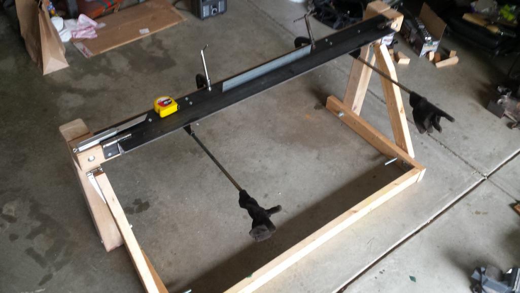
Using test strips to get set up: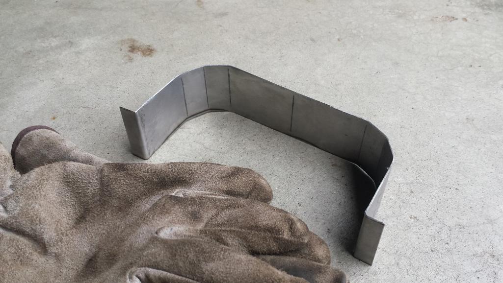
Breakfast of champions: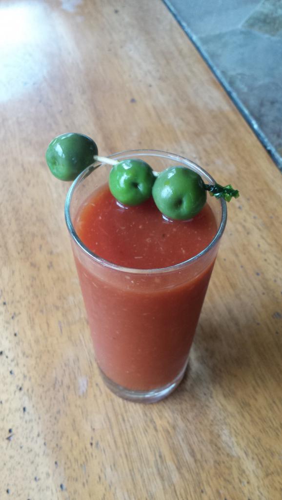
Posted by: DirtyCossack Oct 3 2015, 07:57 PM
So far in my rustoration I'm not finding a need to cut out the fender. Some stuff may require contortionism, but it seems possible.
Posted by: mbseto Oct 3 2015, 08:09 PM
I'm going to try to weld everything from the inside. I'll go as long as I can without cutting the fender. If I get to a point where I have to, I'll take the whole quarter panel off intact.
Posted by: 914forme Oct 3 2015, 08:13 PM
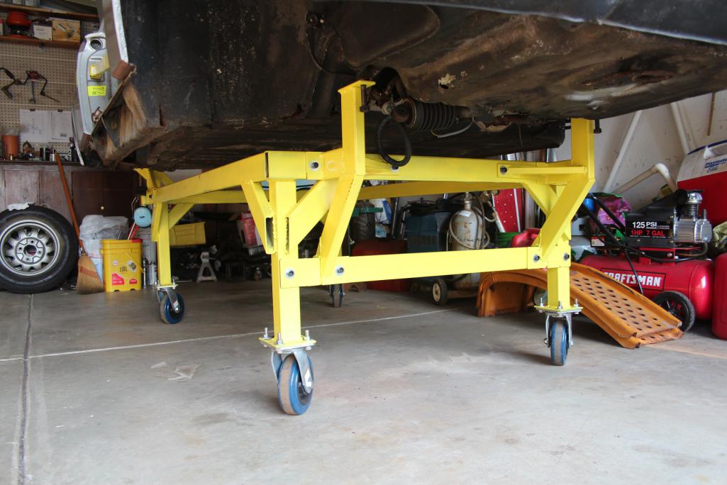
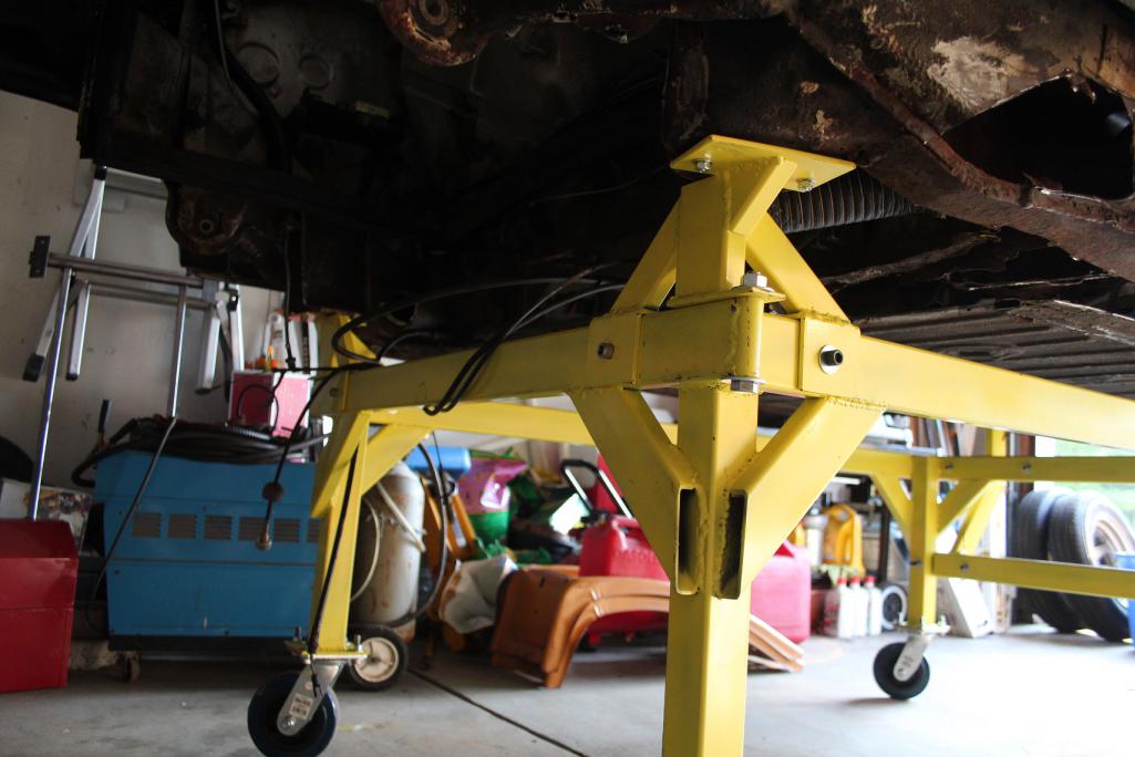
Matthew, I really like the dolly. I will be liberating some of your ideas for the dolly to build my.
Posted by: Vysoc Oct 4 2015, 10:09 AM
Nice Dolly, I will bet that Brake can bend 16g but 12g may be too stout?
Enjoy the build and hang in there!
Vysoc 
Posted by: turk22 Oct 4 2015, 10:29 AM
I'm planning on buying a bunch of sheet metal from RD. But to help stay within budget, I made a bending brake- this will be the source of my new inner longs. I've got a pile of 18g, but I have a piece of 12g to test the limits of this thing. If it can handle it, I may just make the inner longs from 12g. No additional stiffening kit required!
Using test strips to get set up:
Breakfast of champions:
I really like your Bloody Mary setup! I will be liberating that idea before I help my son with his rotor and pad replacement!

Posted by: Andyrew Oct 4 2015, 11:40 AM
Killer dolly setup!!
Posted by: mbseto Oct 5 2015, 08:04 AM
Matthew, I really like the dolly. I will be liberating some of your ideas for the dolly to build my.
Thank you. That's exactly what I did... Combed the site for dolly pics and stole every good idea I saw. That said, there's some things I would do different next time around, just to make life easier on myself.
Posted by: mbseto Oct 5 2015, 08:08 AM
Breakfast of champions:
I really like your Bloody Mary setup! I will be liberating that idea before I help my son with his rotor and pad replacement!
Thanks! Pro-tip: put half your batch in the fridge for a couple days and let that horseradish marinate. Gives it a nice kick, will be good on these upcoming winter mornings in the garage.
Posted by: jmitro Oct 5 2015, 08:44 AM
ha; timely update. I was just ruminating over how to make my own sheetmetal brake.
Can you show a pic of how it works?
Posted by: mbseto Oct 6 2015, 09:51 PM
ha; timely update. I was just ruminating over how to make my own sheetmetal brake.
Can you show a pic of how it works?
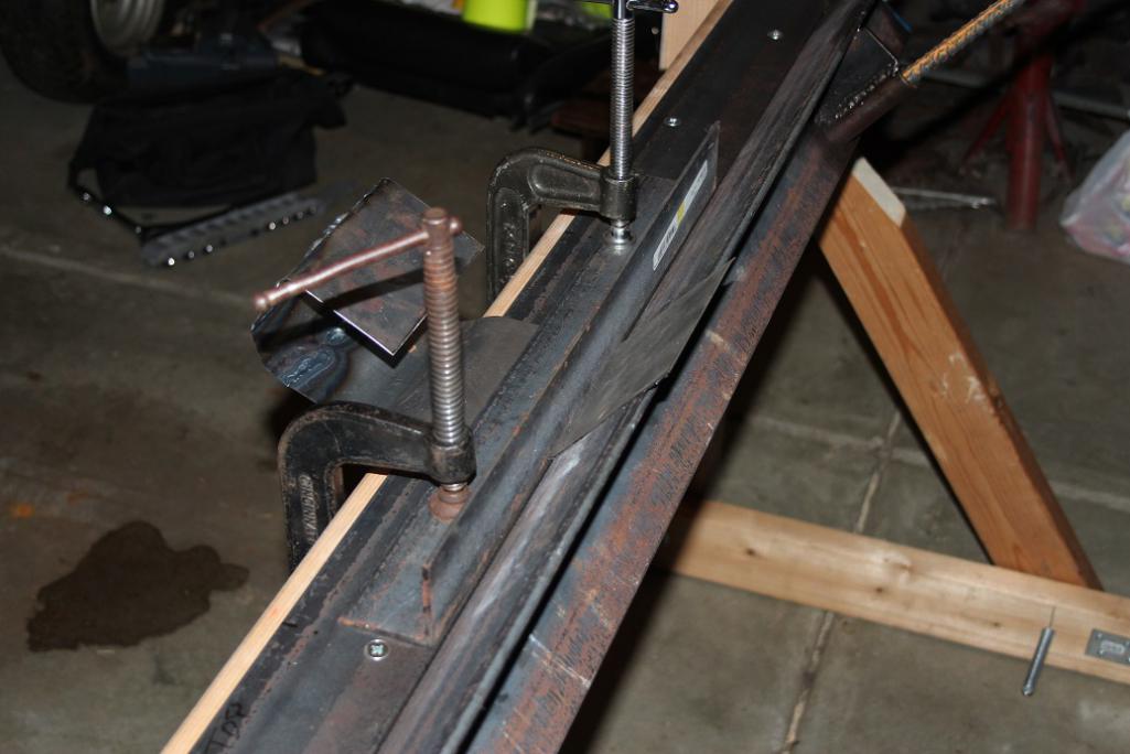
Took these after dark, hope they show it well enough. The brake is just three pieces of angle iron. Two are hinged together and bolted to the stand, the third is used as a clamp. This is what it looks like set up with a small test strip:
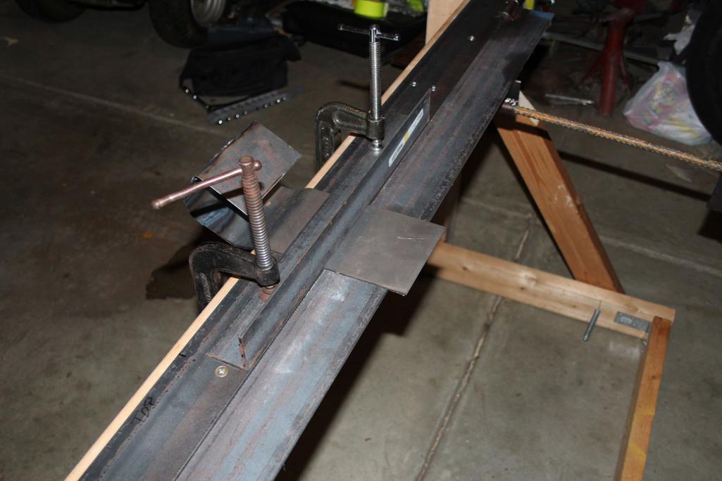
Once the sheet is clamped in place, you just lift up on the handles like so:
Of course it's going to spring back some. You can find tables that tell you how far to bend it so that it springs back to the angle you want. You can also muscle it after the fact.
Here's a close shot of the hinge. It's very simple.
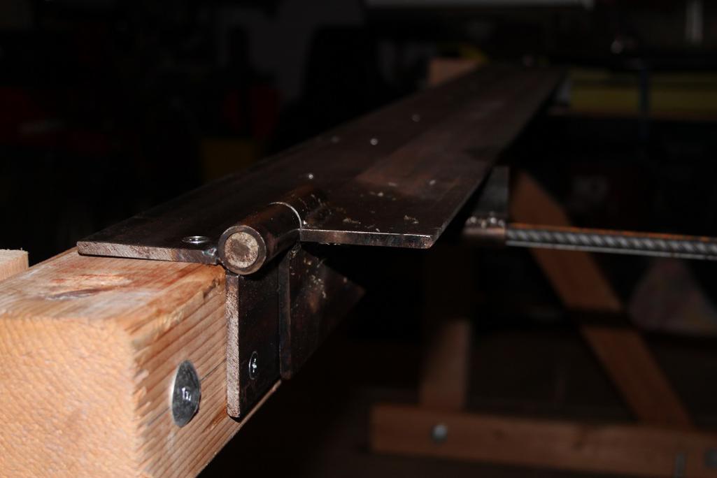
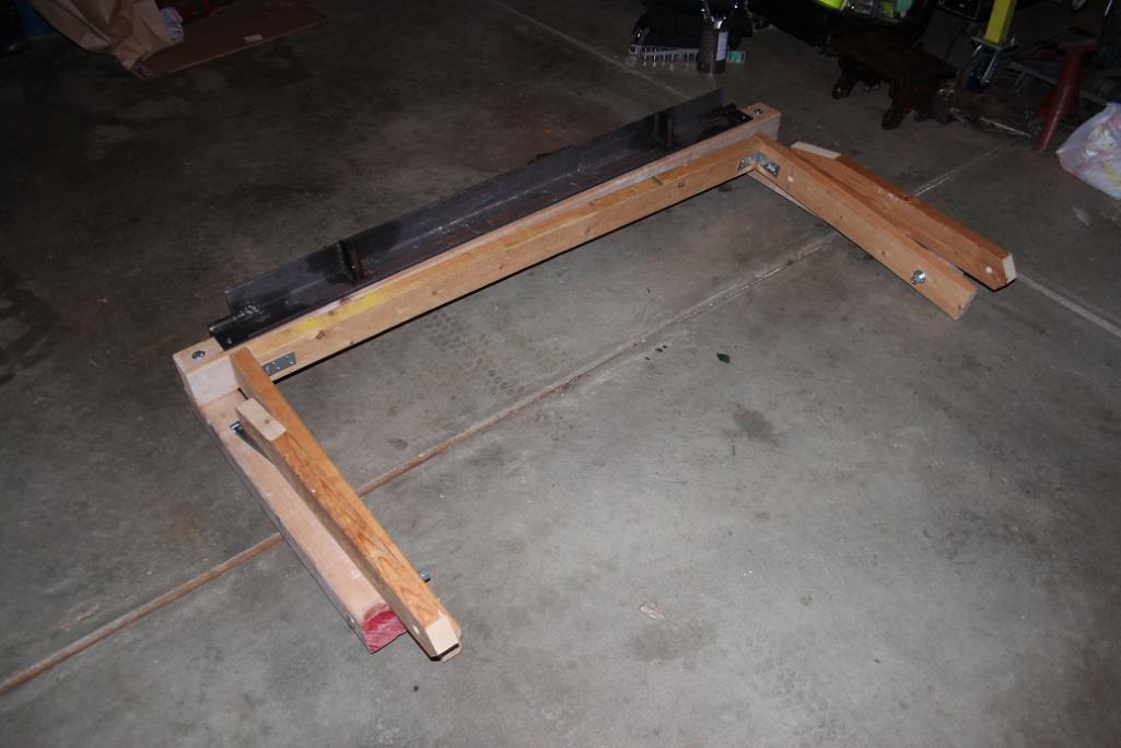
And the best part is, it folds up!
Posted by: Andyrew Oct 6 2015, 09:58 PM
That is awesome... Its so simple!
Posted by: mbseto Oct 9 2015, 08:46 PM
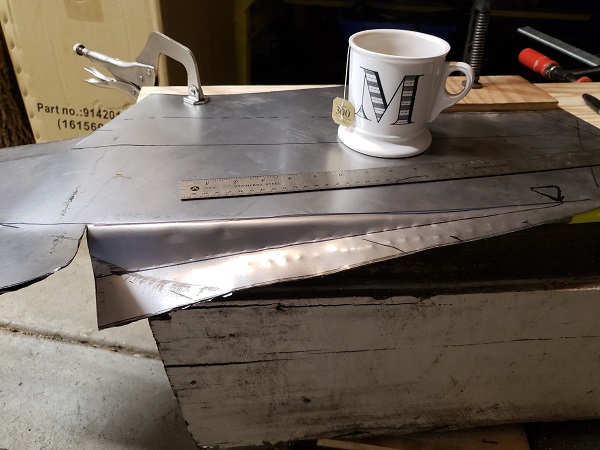
Hammer forming patch for the back part of the forward wheel well where the long attaches. Got to make it healthy before the new long goes in. Three tries, first 2 in 20 gauge for practice, third in 18 gauge.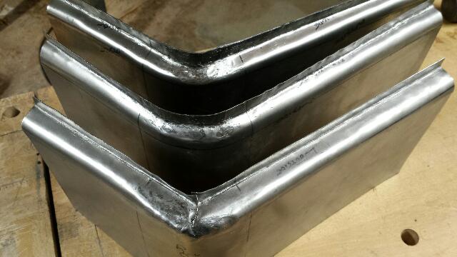
Posted by: mbseto Dec 21 2015, 06:40 PM
You can probably guess where this little monkey is going to go: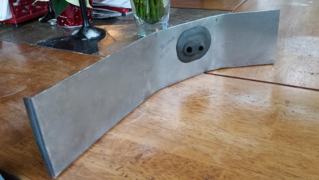
Adjacent layer of the onion/ogre: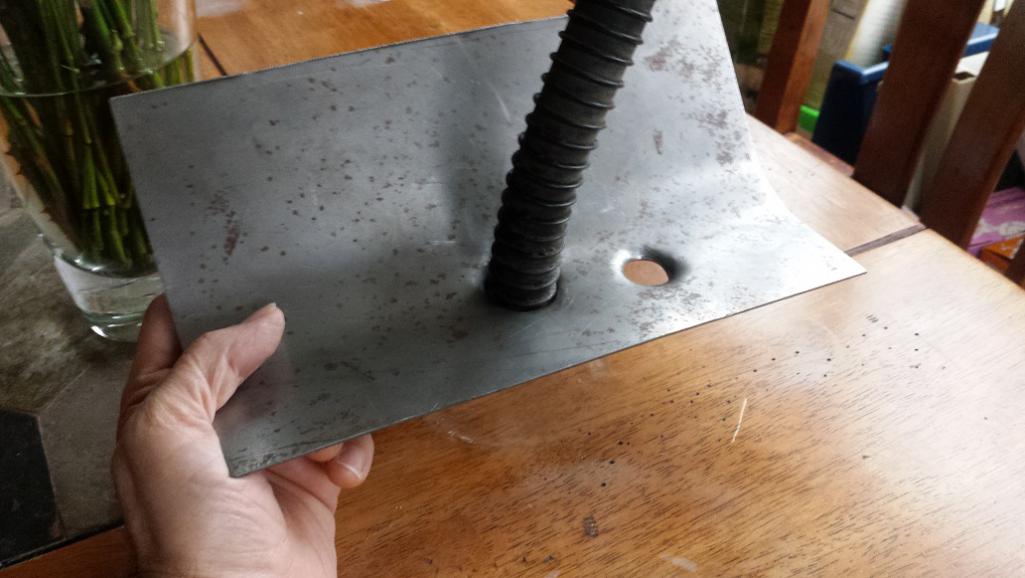
While it's open, here's a picture of the dirty tunnel. Guess I should clean it out before welding it up again...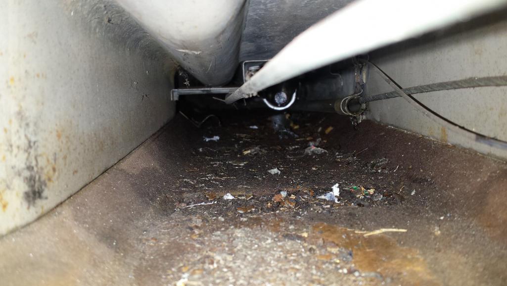
Posted by: tygaboy Jan 18 2016, 03:01 PM
Back at you on the fab skills! And I'll add to the "Awesome dolly!" comments.
Keep up the great work.
Chris
Posted by: injunmort Jan 18 2016, 03:50 PM
awesome work, that tunnel shot looks like a surgical theater compared to mine
Posted by: mbseto Jan 20 2016, 10:11 PM
Time to catch you guys up... Spending some cold January Saturdays with my butt planted on the concrete floor. Love the welding, agnostic on the grinding.
I had a pile of patches that I made in December, all ready to weld in.
Started the month with a big part of the wheel-well/steering-tunnel cut away. 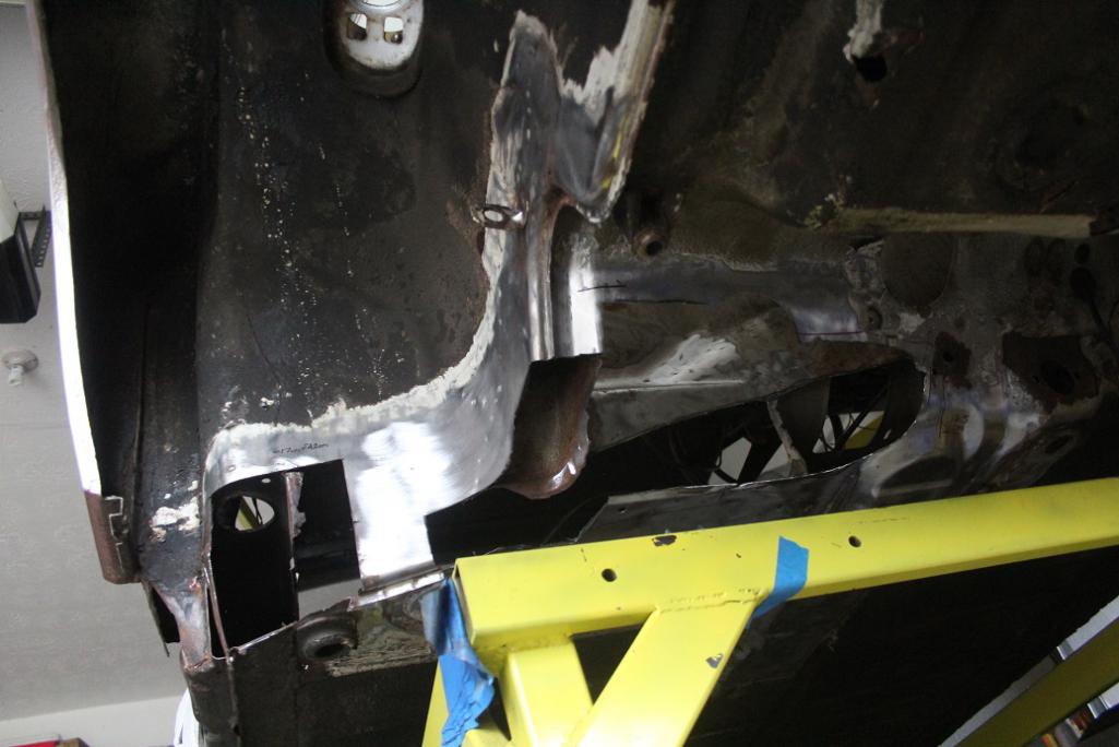
Here's the first patch in the firewall, from the outside and from the inside: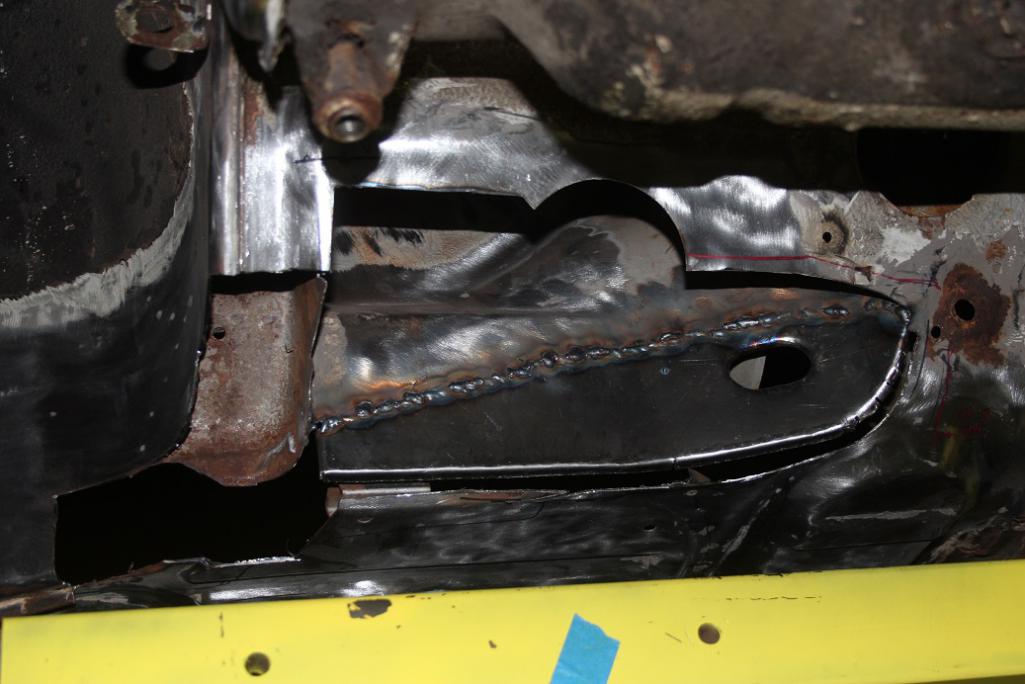
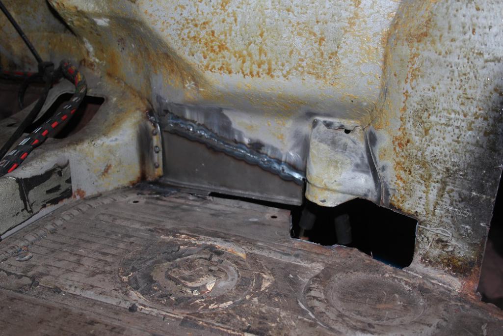
Second patch in the tunnel: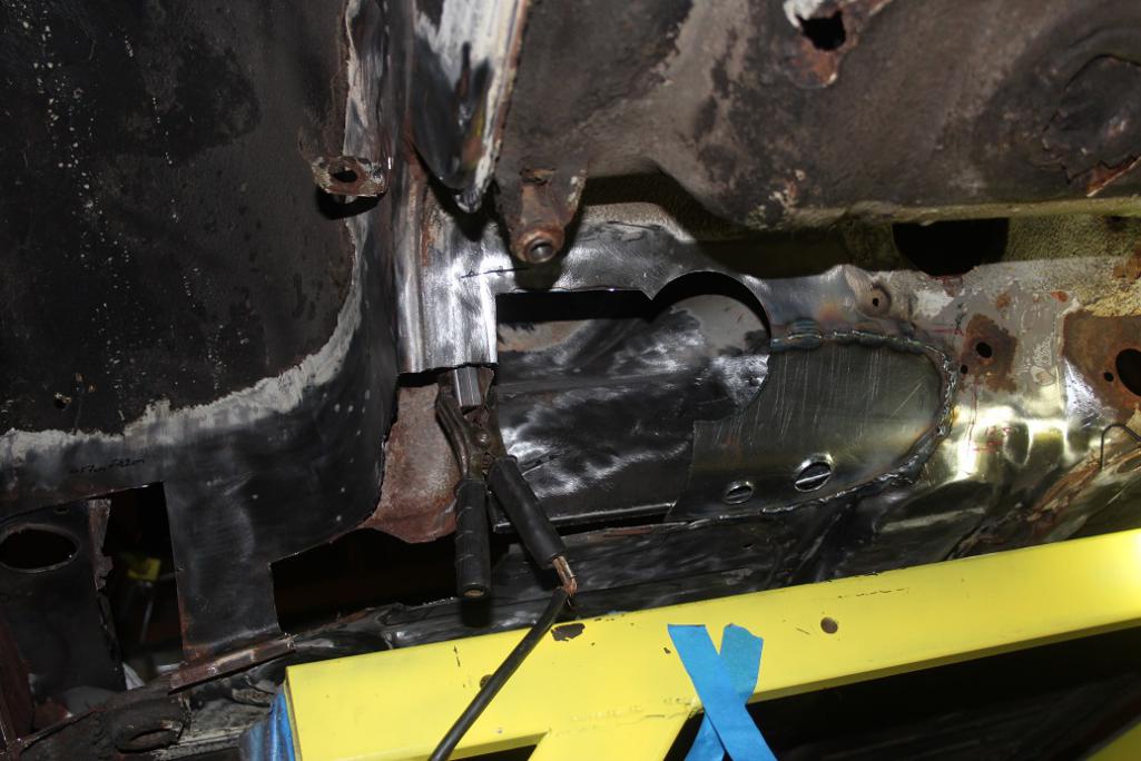
Third patch completes the box section that reinforces the area where the tunnel meets the wheel well: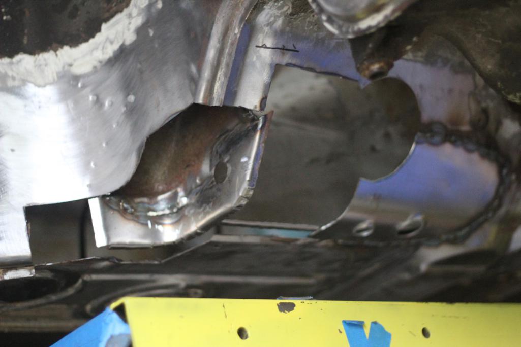
Fourth patch to complete the steering tunnel: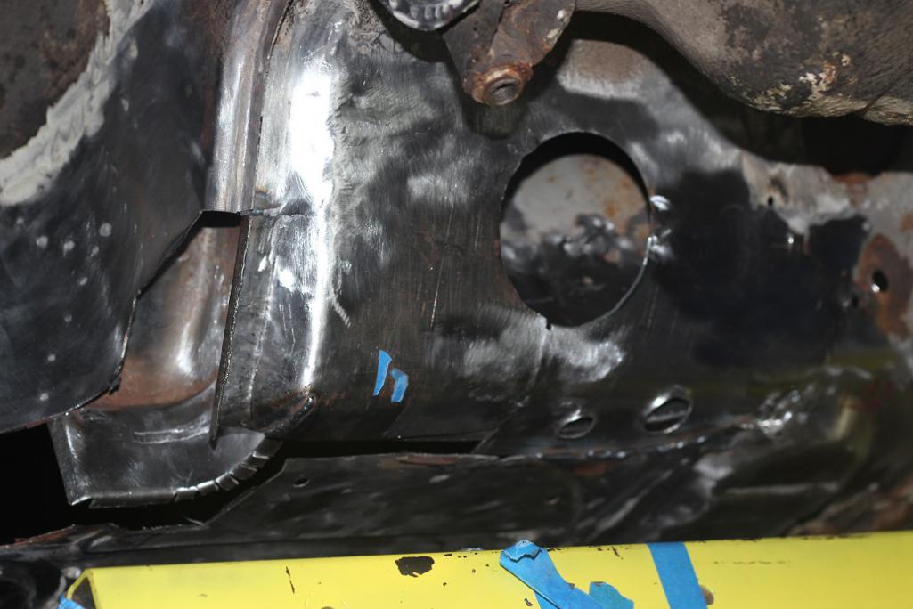
Posted by: mbseto Jan 20 2016, 10:17 PM
Some strategy: Was puzzling over the best way to clean out the center tunnel. I realized that at some point in the process, every edge of the floor would get cut and re-welded. In fact, there's only a few inches of any edge that is not rusted through. So I figure I'll repair the longs and firewall but hold off on welding the floor back, then I'll drop the whole floor, clean out the tunnel and rust-proof, then repair the edges and weld it back in.
Posted by: ssuperflyoldguy Jan 23 2016, 01:10 PM
Just a suggestion, when I do sheetmetal fab on rusty cars, I weld back in galvanized sheet metal. You can find at sheetmetal fabrication shops or order through metal distributors. At the very minimum, clean n prep metal n spray with weld through/cold galvanizing spray. Welding in untreated metal is just putting in new tin worm food.
Posted by: mbseto Jan 31 2016, 10:45 PM
Just a suggestion, when I do sheetmetal fab on rusty cars, I weld back in galvanized sheet metal. You can find at sheetmetal fabrication shops or order through metal distributors. At the very minimum, clean n prep metal n spray with weld through/cold galvanizing spray. Welding in untreated metal is just putting in new tin worm food.
Thanks for the input. I'm a little leery about welding galvanized steel. I don't have a professional-level shop, my ventilation is just a fan. Planning to have the whole thing grit blasted, rustproofed, and painted.
Posted by: mbseto Jan 31 2016, 10:47 PM
Man, the voting is quite a job. Fun to see where everyone is at, I thought I was doing a good job keeping up on all the challenge builds, but there's quite a few I've tagged for a closer look.
Posted by: rick 918-S Jan 31 2016, 10:53 PM
Lots of hand fab work. nice.
Posted by: mbseto Feb 29 2016, 09:46 PM
Slow month. But started working on the tank. Dumped all the rust out: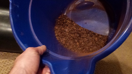
Filled it full of electrolyte and plugged it in. What could go wrong?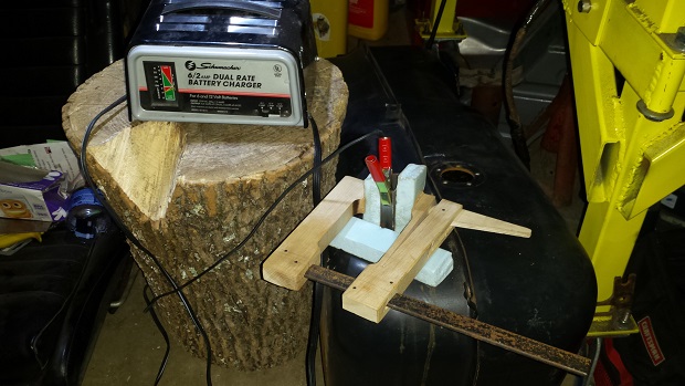
Posted by: mbseto Mar 6 2016, 09:42 PM
Results of electrolysis on the tank. I would turn on the battery charger and let it run overnight. The sacrificial electrode would get covered in rust and slowly the current would drop until it was too rusty to conduct. Each morning I shut it off and pulled the electrode out. After work, I would clean it up and stick it back in and do it all over again. This is the result after 4 or 5 sessions... before and after: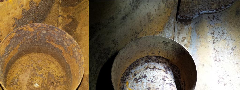
On a side note, my HF grinder spindle lock got really loose a while back and has been having trouble holding the spindle while I change discs. Took a few minutes and took the head off. Thought I'd take a look, although even 30 minutes is too much to spend fixing a 14 dollar tool. Turns out the casting broke away where it supports that little lock pin. Going to put up with it for now, if I get bored at some point I make get mix some JBWeld and fix it.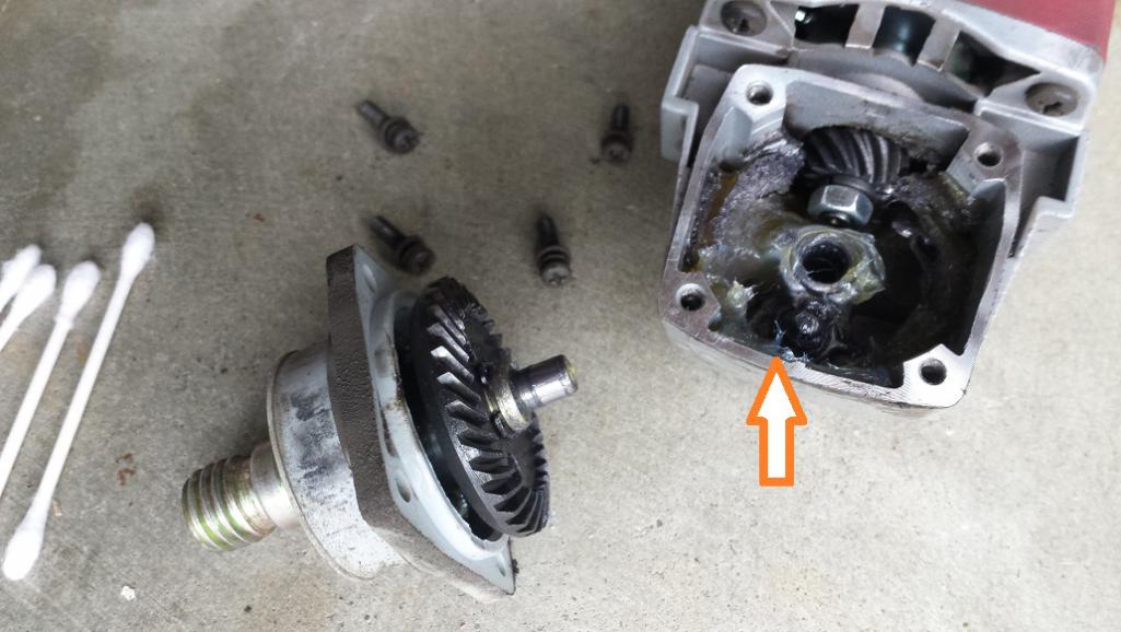
Posted by: mbseto Jul 6 2016, 09:42 PM
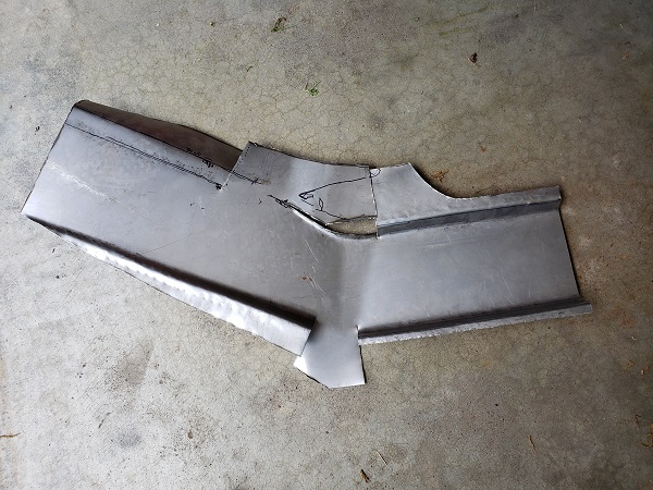
Front passenger corner is pretty much rebuilt and strong, ready to support the front end of a brand new long.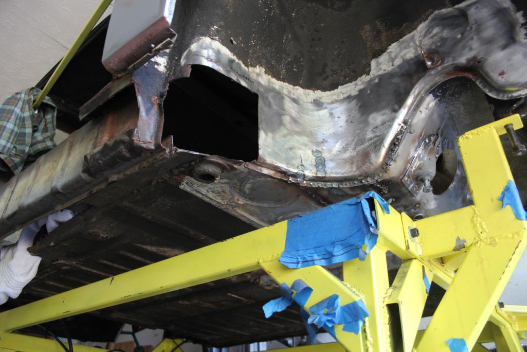
That gaping hole that's left needs to have a piece that wraps around the corner and then extends into the long. I.e., it will be sandwiched between the two halves of the long. Here's the piece with the two halves: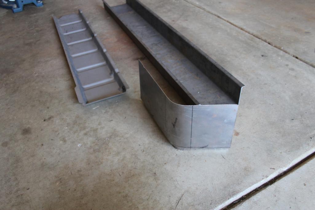
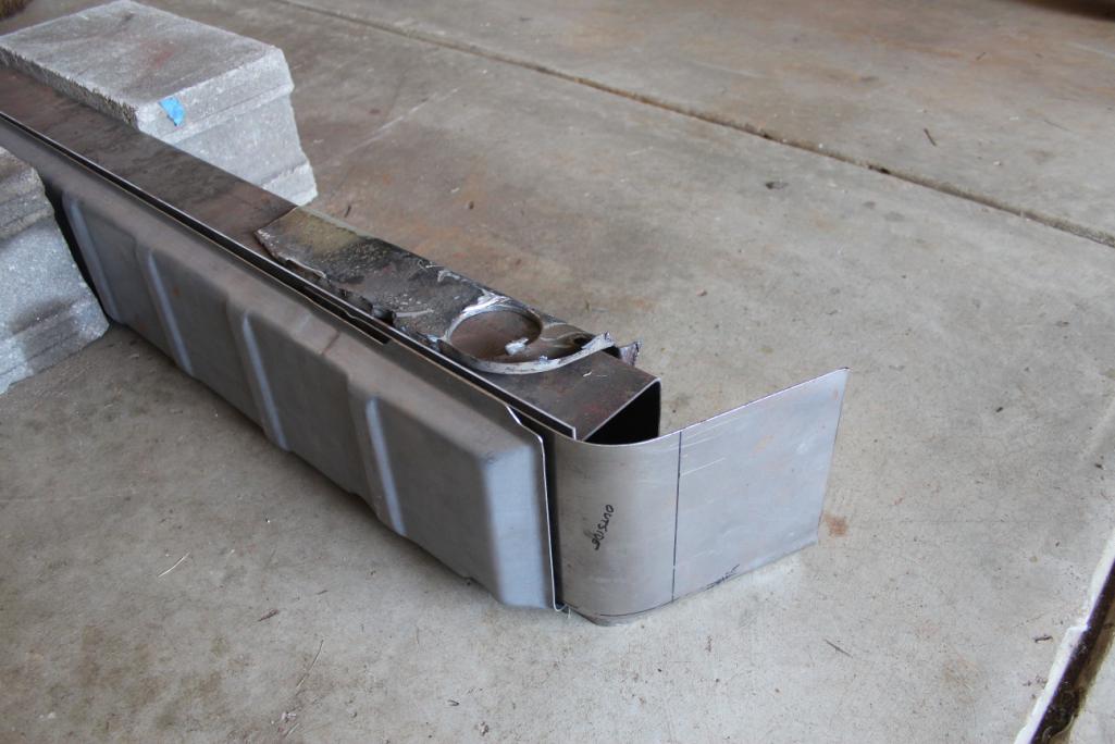
More on this later. The next step is to get the old long out of the way so this piece can be added in first.
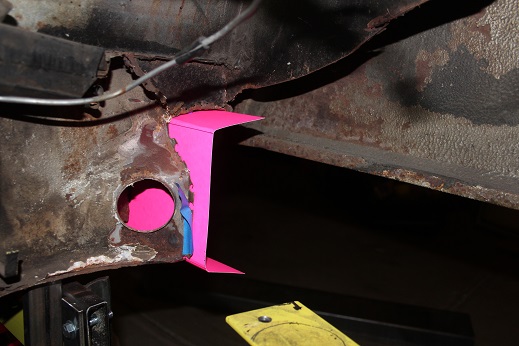
Posted by: mbseto Jul 6 2016, 09:47 PM
Now you see it, now you don't...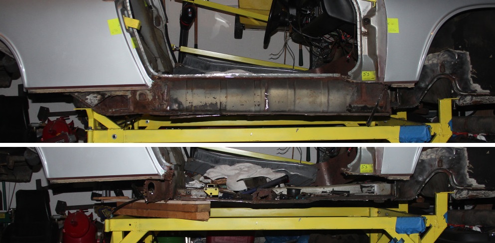
Final corner piece in, ready to fit the long: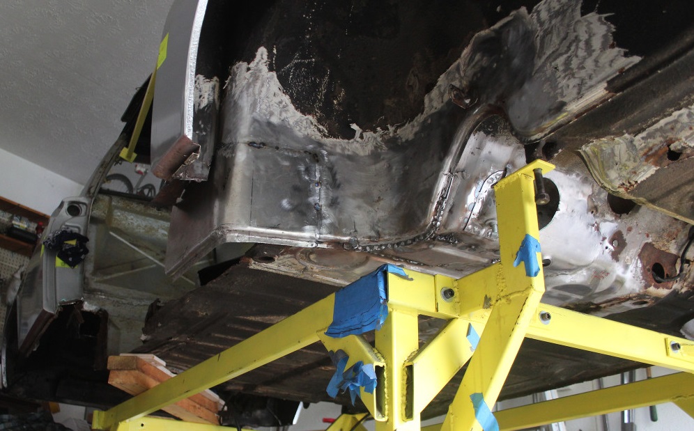
Posted by: mbseto Jul 6 2016, 10:11 PM
Anatomy Autopsy of a long...
Here's the whole thing as it came out. You see a lot of it missing with straight edges as if it were cut away. In reality, this was mostly rusted away and the jagged rusty edges were just trimmed off.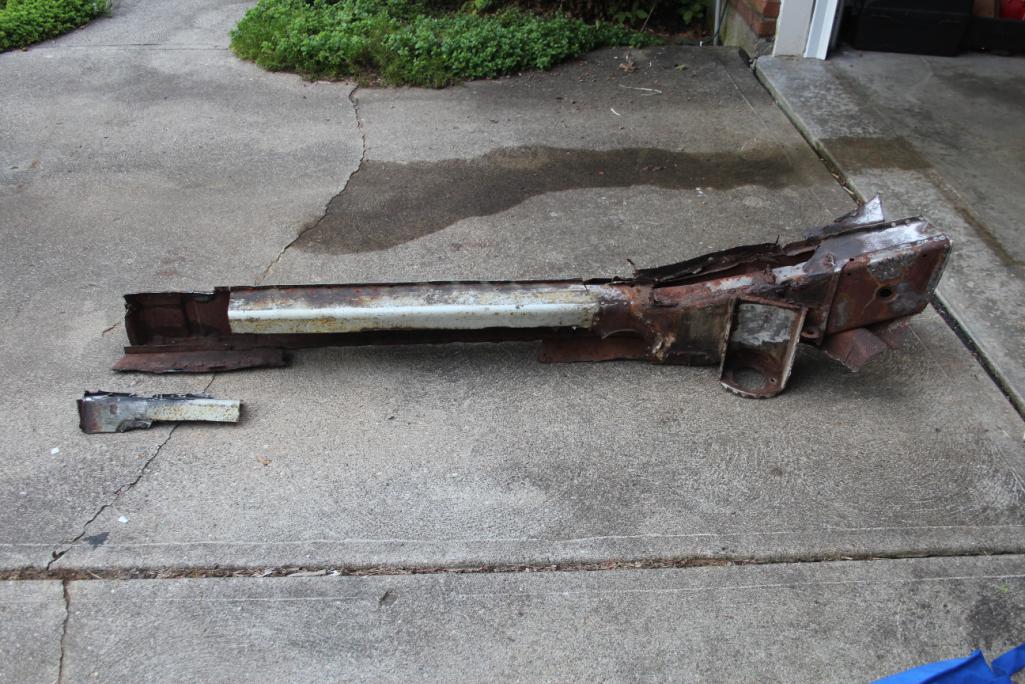
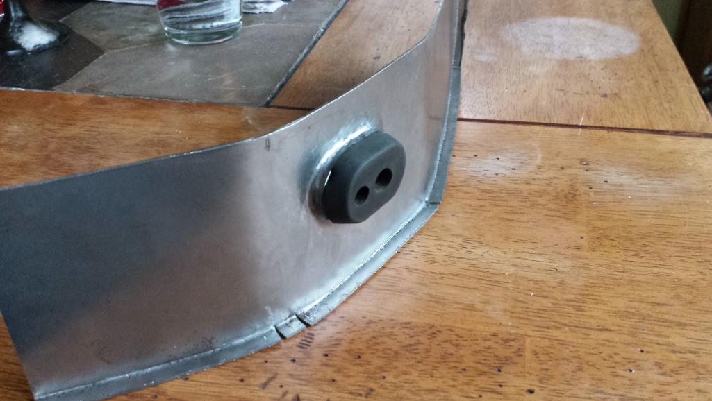
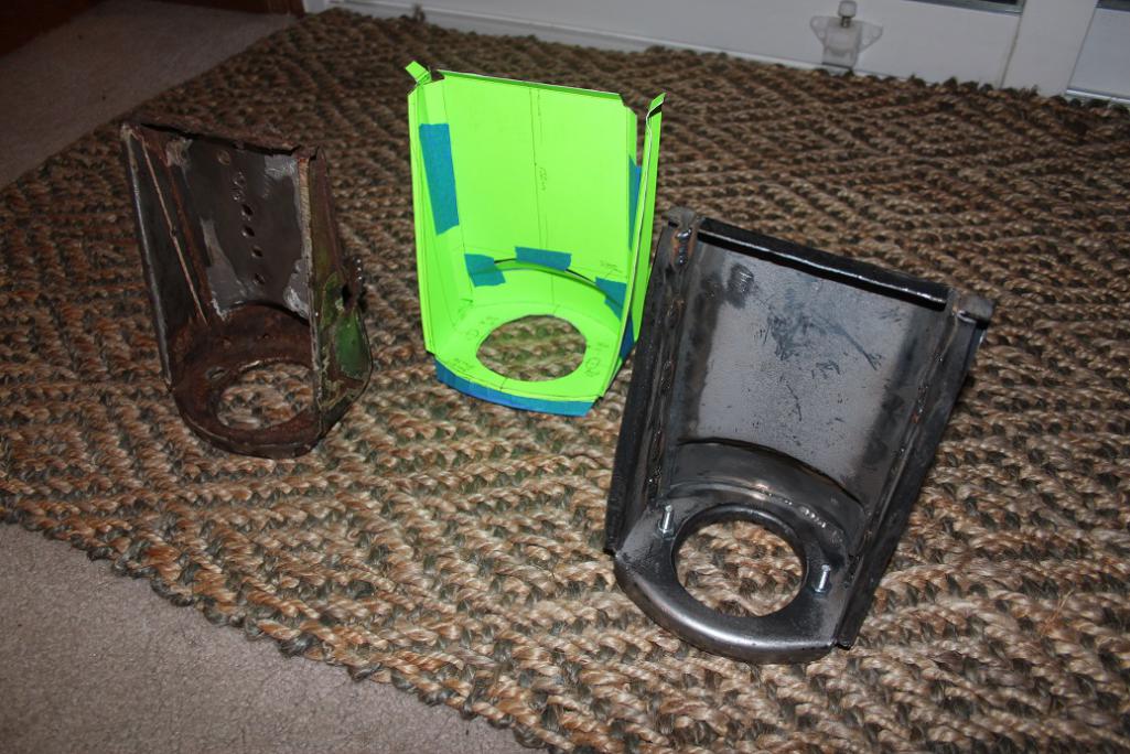
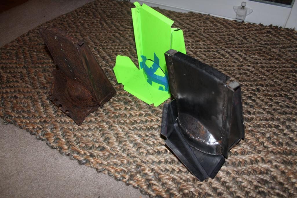
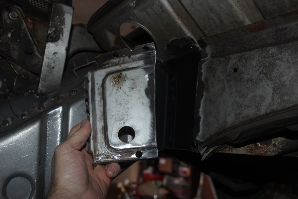
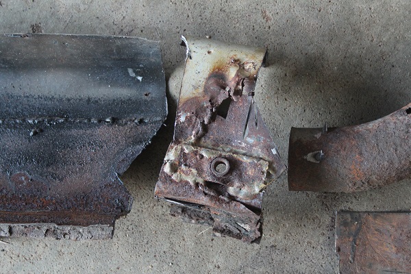
Condition of the motor mount. Going to remove this and clean it up, see if it can be saved. The hole on top was covered by a couple rectangular patches that looked like the were hammered in place and welded on- I think I posted pics earlier. Took them off when I cut out the engine shelf.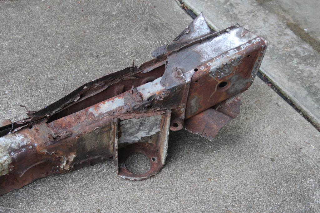
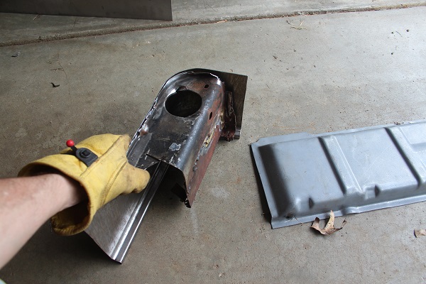
Condition of the pylon. Don't think this can be saved. There's a nest inside it, I'm afraid it is corroded from the inside beyond help. Have a little wager whether I'm going to find a little mouse skeleton inside.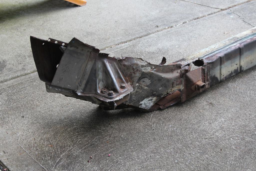
Patchwork around the jack point. I was more critical of the previous work on this until I start welding my own patches in. 
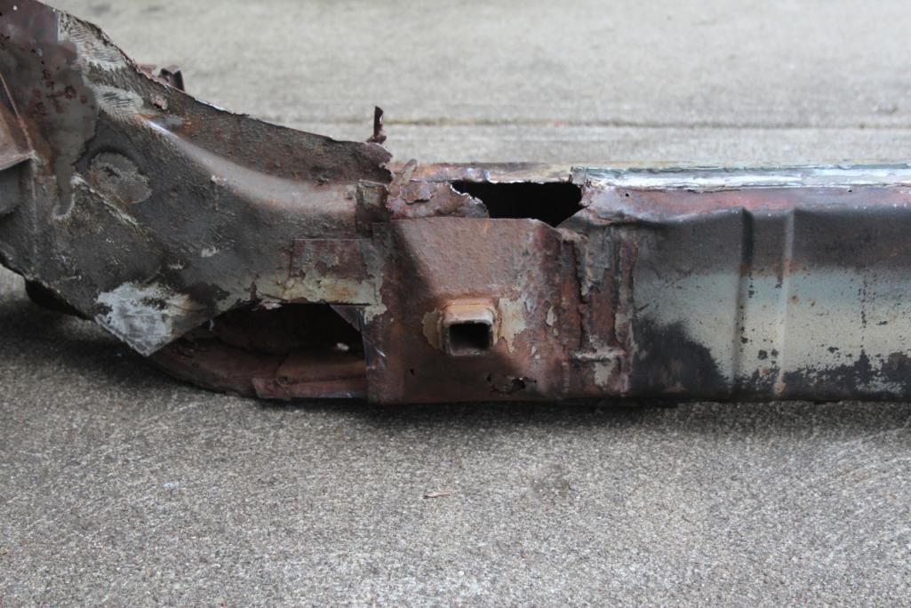
More patch work...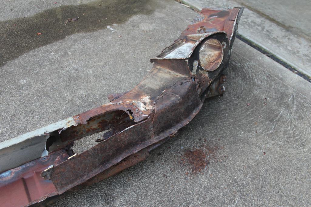
And the forward section...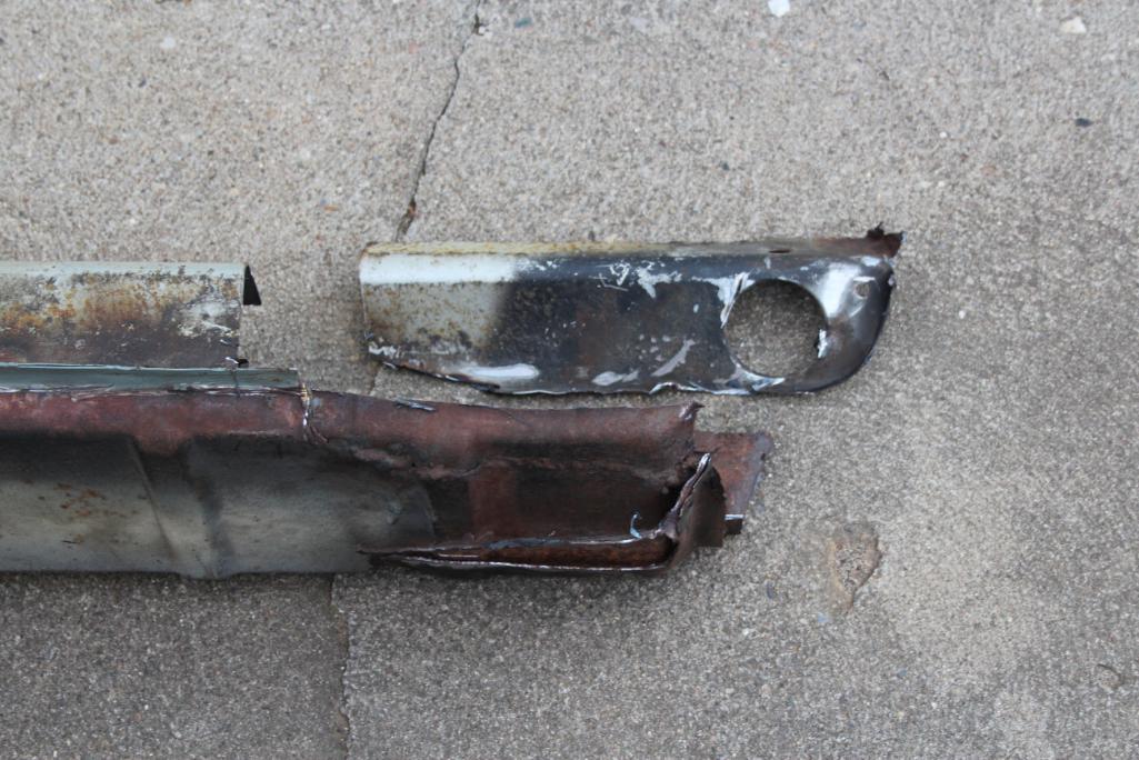
So in the end, hoped to have an educational experience in seeing how the frame is put together. I did learn a lot, but feel a little like a doctor that learned anatomy by dissecting a zombie. I hope I'm building a better Frankenstein.
Posted by: 914forme Jul 7 2016, 11:44 AM
Cool, I love dissections.
Posted by: mbseto Jul 18 2016, 07:10 PM
Had a shop bend channel sections in 12g. Did the rest myself.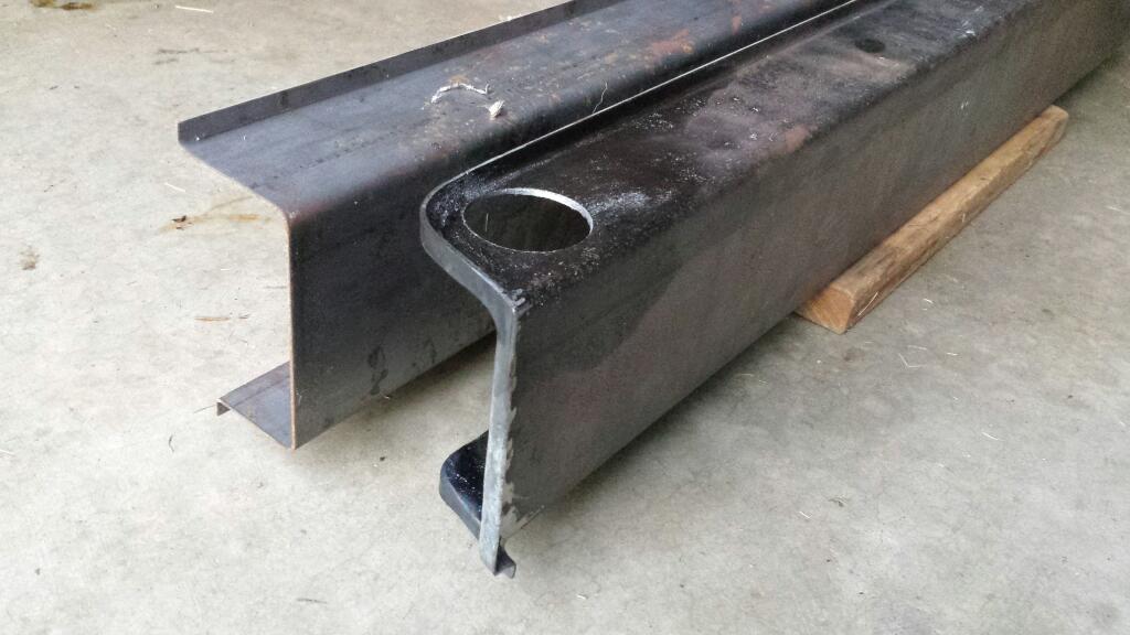
Posted by: Andyrew Jul 18 2016, 08:45 PM
12ga? Holy crap...
Posted by: mbseto Jul 19 2016, 09:37 AM
12ga? Holy crap...
That's the standard gauge plus the stiffener kit.
Posted by: DirtyCossack Jul 19 2016, 09:40 AM
That's awesome right there.
Posted by: buck toenges Jul 19 2016, 09:53 AM
How are you going to refinish your fuel tank on the inside?
Posted by: mbseto Jul 19 2016, 10:00 AM
Thinking of getting the POR15 kit. I'm planning to boroscope the inside to make sure it looks OK all the way to the back, I'll post that once I do it.
Posted by: jd74914 Jul 19 2016, 02:28 PM
Thinking of getting the POR15 kit. I'm planning to boroscope the inside to make sure it looks OK all the way to the back, I'll post that once I do it.
I'd recommend the Caswell Platings kit instead if you haven't already gotten the POR15 kit. I've used it on a few tanks and been very happy.

Would you mind sharing the cost of getting those longs bent? No pressure, just curious.
Posted by: DirtyCossack Jul 19 2016, 04:10 PM
When I move back to CVG next year we're going to have to meet up at the Hoffbrau Haus to tell war on rust stories. Or at our workshops if we don't have these cars done...
Posted by: 914forme Jul 19 2016, 05:43 PM
When I move back to CVG next year we're going to have to meet up at the Hoffbrau Haus to tell war on rust stories. Or at our workshops if we don't have these cars done...
Oh wow, I doubt I'll be done
That is crazy having your own logs bent up, but not a bad idea. You did great work on them.
Posted by: trojanhorsepower Jul 19 2016, 06:05 PM
Wow! A complete longectomy.
The replacement looks great.
Posted by: mbseto Jul 19 2016, 09:10 PM
Would you mind sharing the cost of getting those longs bent? No pressure, just curious.
$210 for both.
Posted by: mbseto Jul 19 2016, 09:13 PM
When I move back to CVG next year we're going to have to meet up at the Hoffbrau Haus to tell war on rust stories. Or at our workshops if we don't have these cars done...
Oh wow, I doubt I'll be done
That is crazy having your own logs bent up, but not a bad idea. You did great work on them.
Absolutely- done or not, it looks like we've all got enough stories to get us through a couple rounds.
Posted by: jmitro Jul 20 2016, 08:26 AM
That's really nice work you're doing. once the longs are welded in and together, you should spray the inside with the Eastwood internal frame coating or something similar.
Posted by: mbseto Jul 25 2016, 08:33 PM
More dissection... Cut the suspension pylon and motor mount out to see if it could be salvaged though I was pretty sure they were a lost cause. I think I was right, here's the result...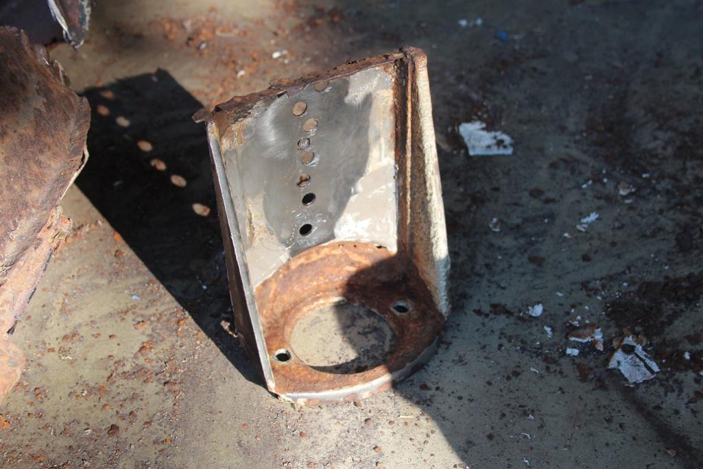
Hydrogen hydroxide: if it can do this to car parts, imagine what it does to your insides!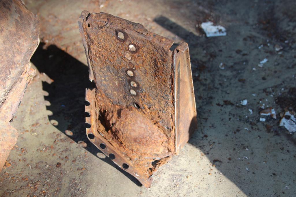
Nobody makes these do they?
Got the mouse nest- no mice left, I guess they figured the old house was no longer structurally sound. Little mouse inspector probably condemned it...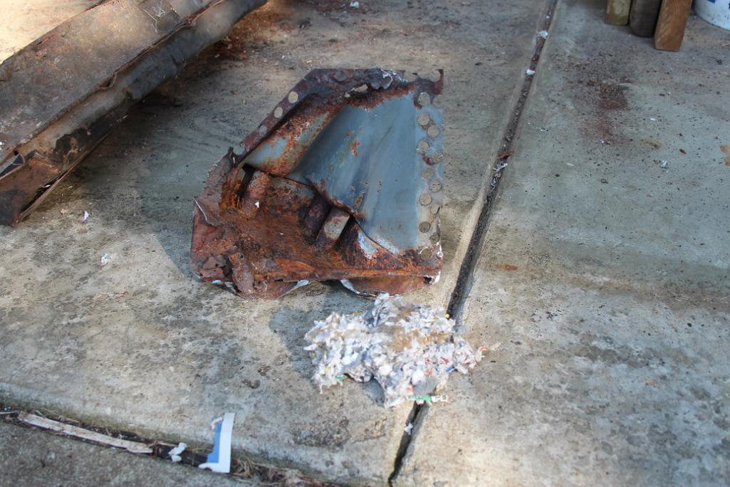
Posted by: mbseto Aug 21 2016, 10:11 AM
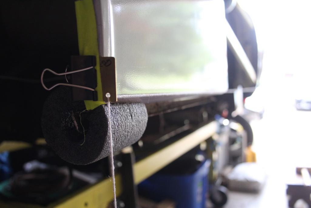
With that long completely cut out, it is pretty floppy and I no longer have a place in the rear corner to grab it. The two hurdles I'm looking at now are, how to level it and how to know when it's level. First, I need a way to support that loose corner, and ideally something that is adjustable. Had an old broken c-clamp laying around...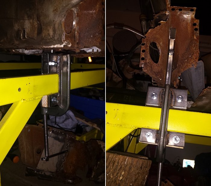
One of the problems with having the whole long out is that there is no motor mount and no suspension mounts- nothing to hold on to and no reference. However, the lower section of the rear firewall has a level flange- it can serve as both a reference and a support.
This clamp adjuster is two pieces: a T welded from stock which slides up between the layers of the lower FW and registers against that horizontal flange, and the clamp with some brackets welded on to affix it to my dolly. I can turn the screw to raise or lower that corner. It all sits inside where the long would be so it will not interfere with my welding.
Posted by: mbseto Aug 21 2016, 10:23 AM
Now the car is mounted on 4 points again and I can adjust to get those points level. But the two halves are tilted away from each other. I can adjust the door braces to fix that, but I need to know how much.
I made a couple little metal tabs with a hole, and clamped them to the corners of the wheel wells, front and back.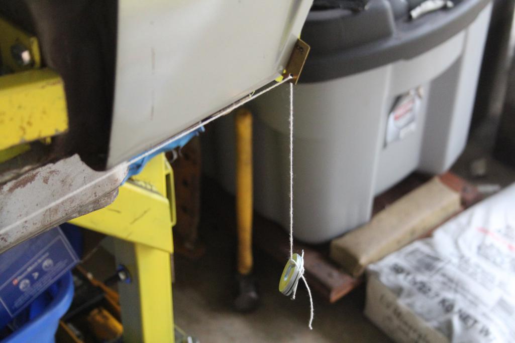
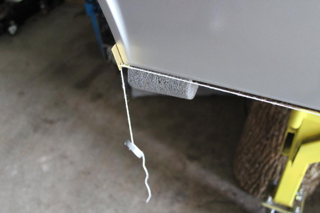
Now I can see if the bottom edges of the quarter panels line up or not...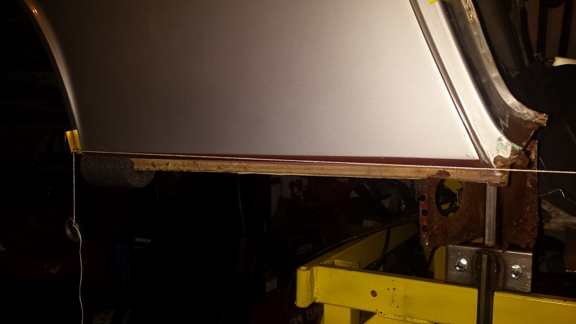
Then I can crank on the door braces to tilt the halves until they line up...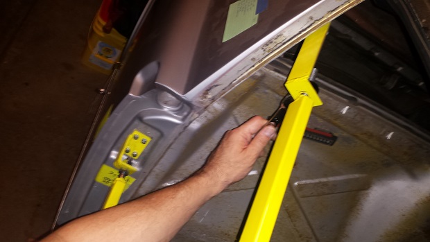
Looks better: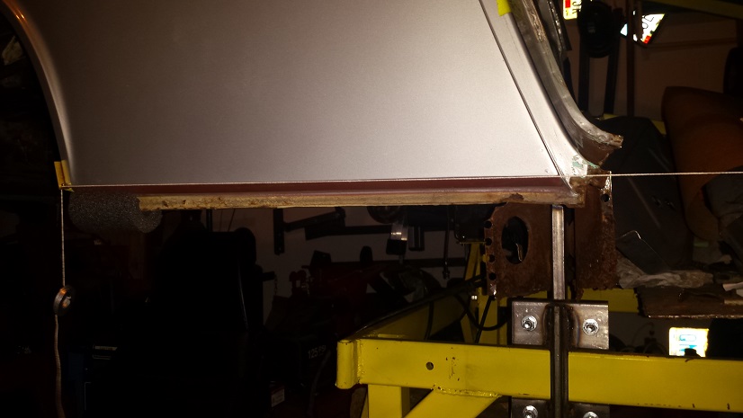
Now I'm sure someone is thinking, what about door gaps? I haven't forgotten...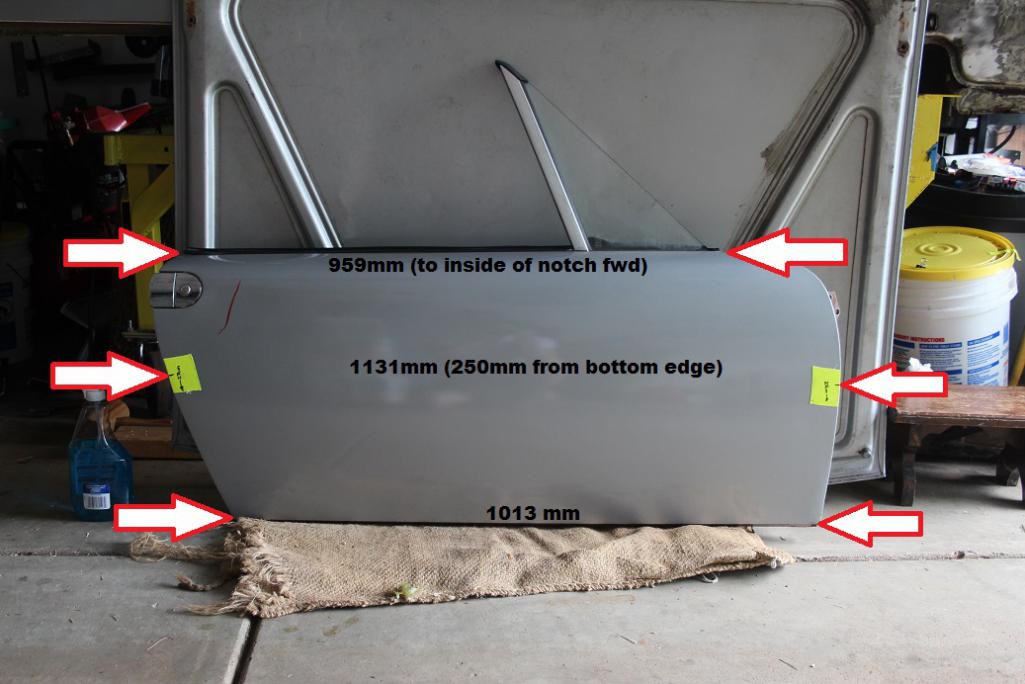
The door braces have to be adjusted in tandem to get the gaps right and also the alignment. That said, getting this right is probably the thing I am most worried about.
And a little postscript... Took a hint from Jeff Hail's thread and got myself one of these little monkeys. I've seen them for as much as $30 at industrial and car places... Home Dep has them for $8 and change.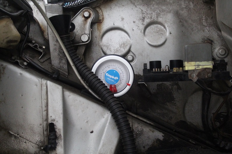
-
Posted by: jmitro Aug 29 2016, 11:10 AM
Very nice work. i'm impressed with your forethought and creativity.
Reading this is making me think I need to redo my longitudinal restoration.
Posted by: mbseto Aug 29 2016, 09:21 PM
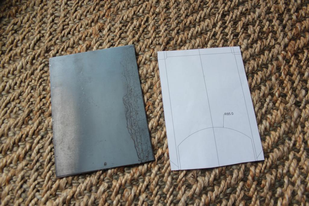
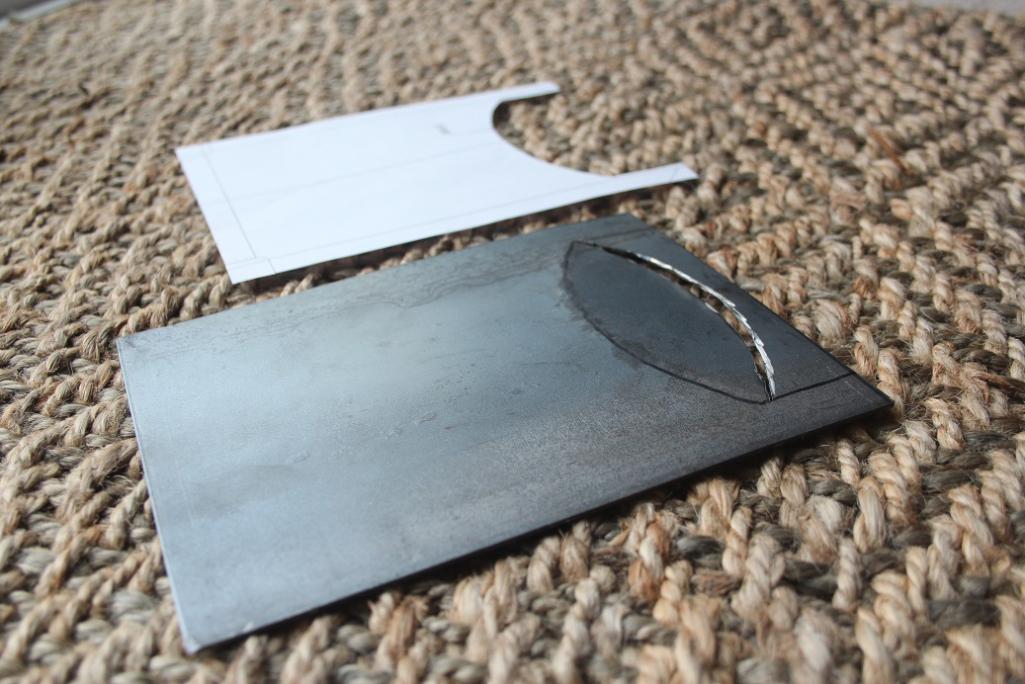
Continuing work on fabricating the inner long. Need to cut the aft hole for the heater tube. Made some templates..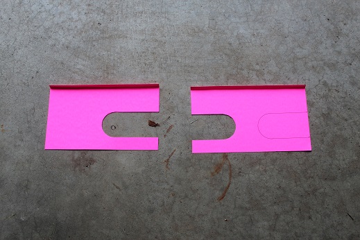
Put the heater tube in position and slid the templates together and taped them.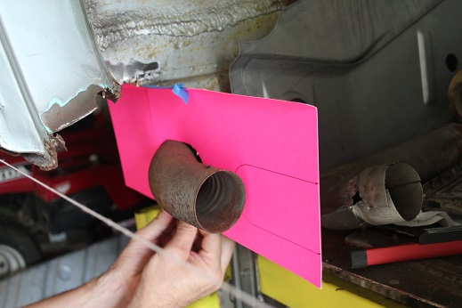
Removed the heater tube, leaving the templates in place...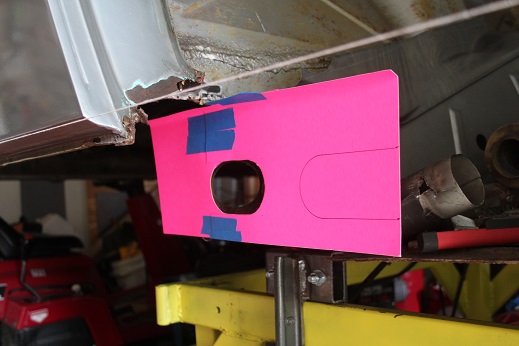
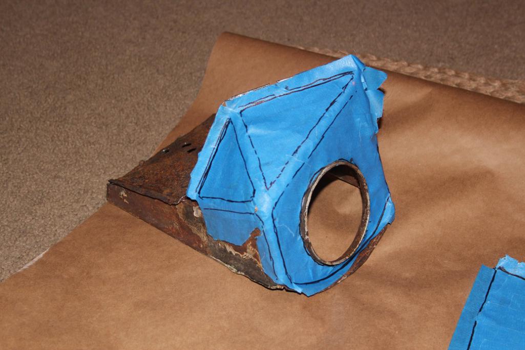
...put the long in place and taped the templates to the long.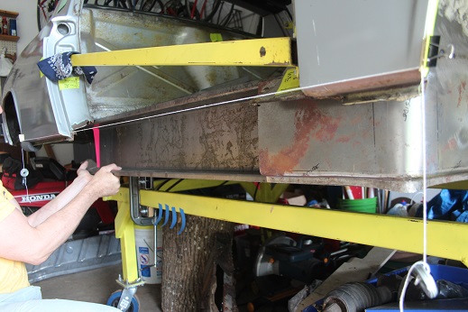
Trace out the hole and cut.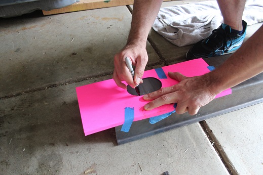
Et voila.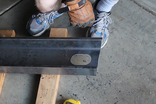
Posted by: mbseto Aug 29 2016, 09:33 PM
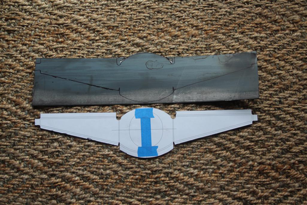
Puzzled over how to match up the inner long to the wheelhouse long, decided on a similar process. What you will not see in this series is me levelling the car across the little ledge in the firewall and constantly measuring the door gaps. I'm checking these at intervals as I go.
Made a template to represent the inner long. It's taped to the body. I've mode some witness marks on it so that I can remove it and then put it back in the same place.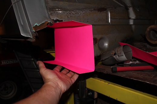
Put the wheelhouse long in place...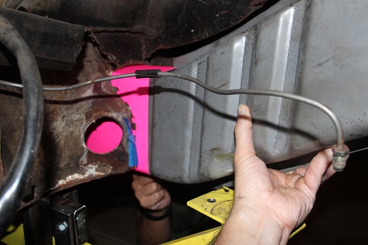
...and traced the edge on the template.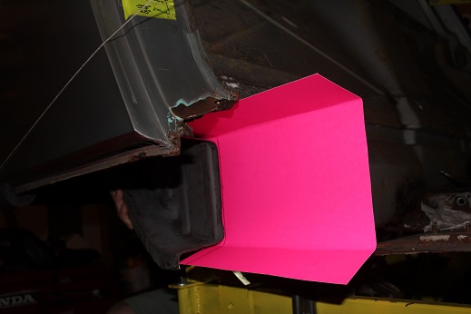
Removed the wheelhouse long.
The template is then removed, cut on the traced line, and then replaced using the witness marks.
Then I put the inner long in place over the template.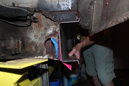
Taped the template to the inner long.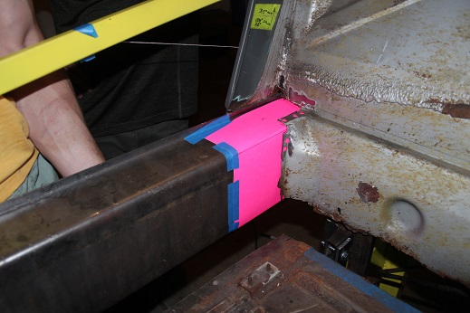
Traced it and cut. Cut outside the line a bit so I have a little room for adjustment.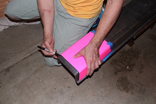
Posted by: mbseto Aug 29 2016, 09:40 PM
Test fitting the heater tube.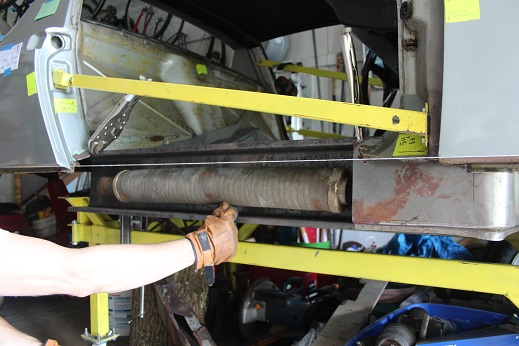
Going to need a little adjustment work to get all this fitting together.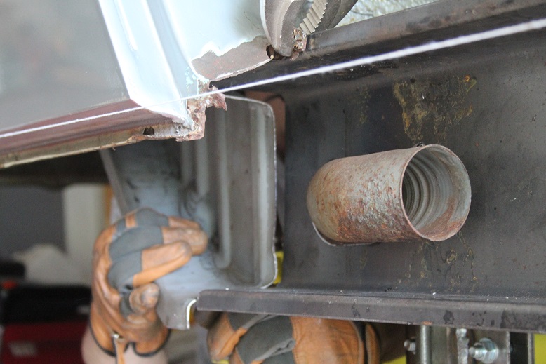
I just like this picture.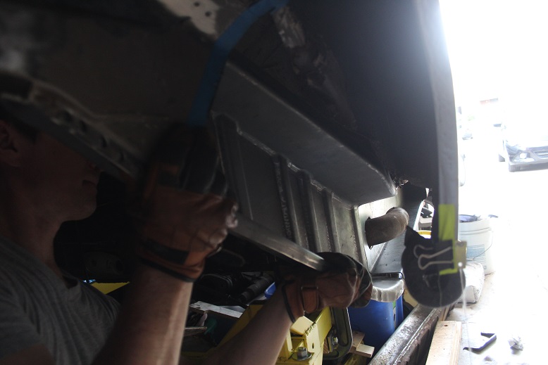
I'd be lying if I said I wasn't a little excited to see all this healthy metal so close to being in the car. A good strong backbone again.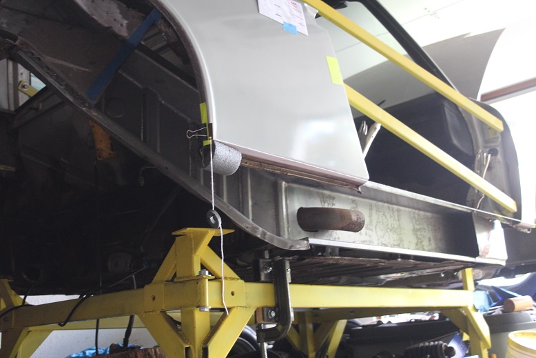
Posted by: 914forme Aug 30 2016, 06:00 AM
 Loving the work, We all know how frustrating this stuff can be. Your doing a great job. And the attention to detail is phenomenal.
If I could make a suggestion. I would get my pieces aligned, then add a scab plate to the inside over the joints. Jeff shows this in his thread also. larger the plate the better. Just remember to coat it between the plates.
Posted by: mbseto Aug 30 2016, 11:43 AM
Thank you!
I definitely plan to sleeve that joint. Truth is I'm still a ways from welding this all together- that wheelhouse long looks like it was made to attach to whatever is left of the long that was cut out, not extend to the trunk wall. Well, I cut mine out completely so I need to make some tabs to bridge that gap. I'll post photos of that process. Then get that butt joint lined up which will require squeezing the one side so the walls are at right angles and tapering the other to match the height of the section. Then I'll make a sleeve. Finally some primer, and I think I'll be close to welding.
Posted by: mbseto Aug 31 2016, 10:43 AM
Acquired a mascot: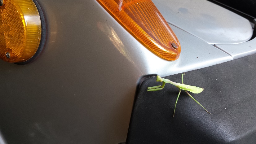
Posted by: mbseto Jan 2 2017, 05:00 PM
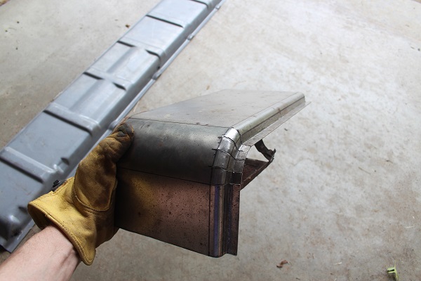
Getting behind on my updates. Got the long sleeved before Christmas...
Made it in three pieces from 12g steel (because the long was already fabricated in 12g...) EDIT: sleeve is 14g: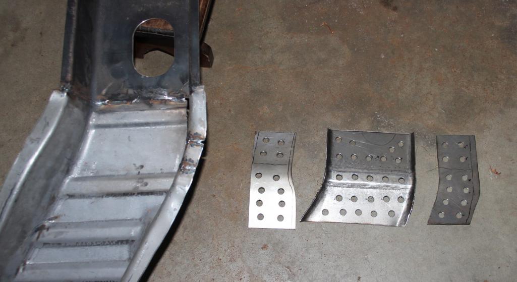
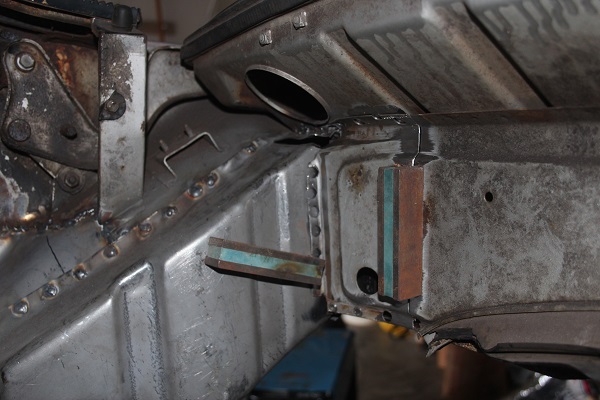
Checking the fit: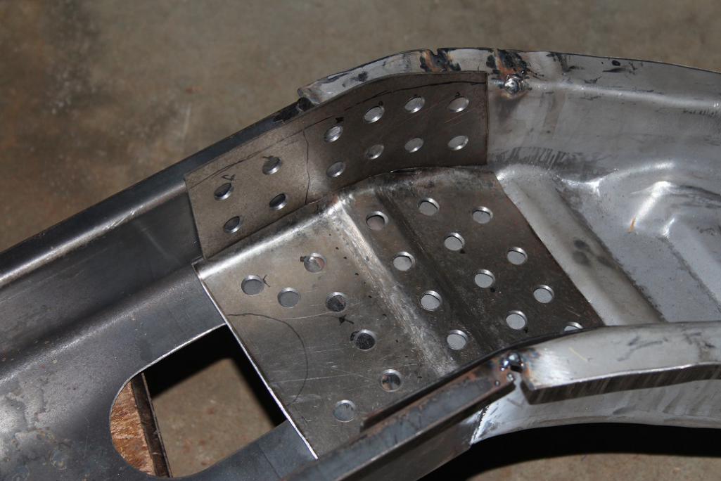
Clamped in place to tack together: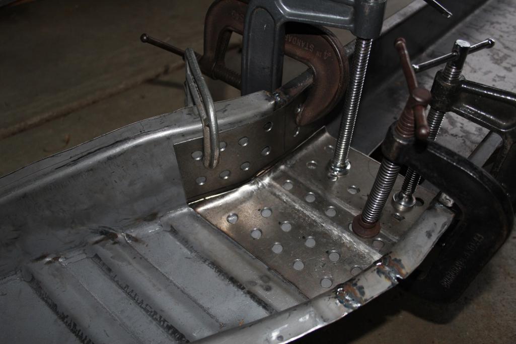
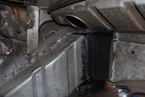
All tacked up: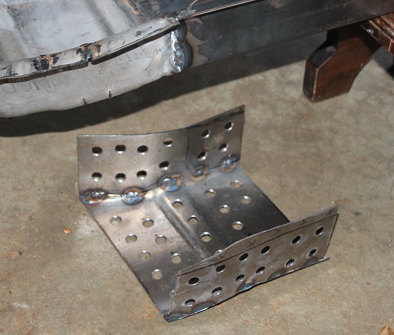
Welded those seams up solid. Did a little trimming, also sprayed on some weld-thru primer to both pieces before the final weld up.
In situ: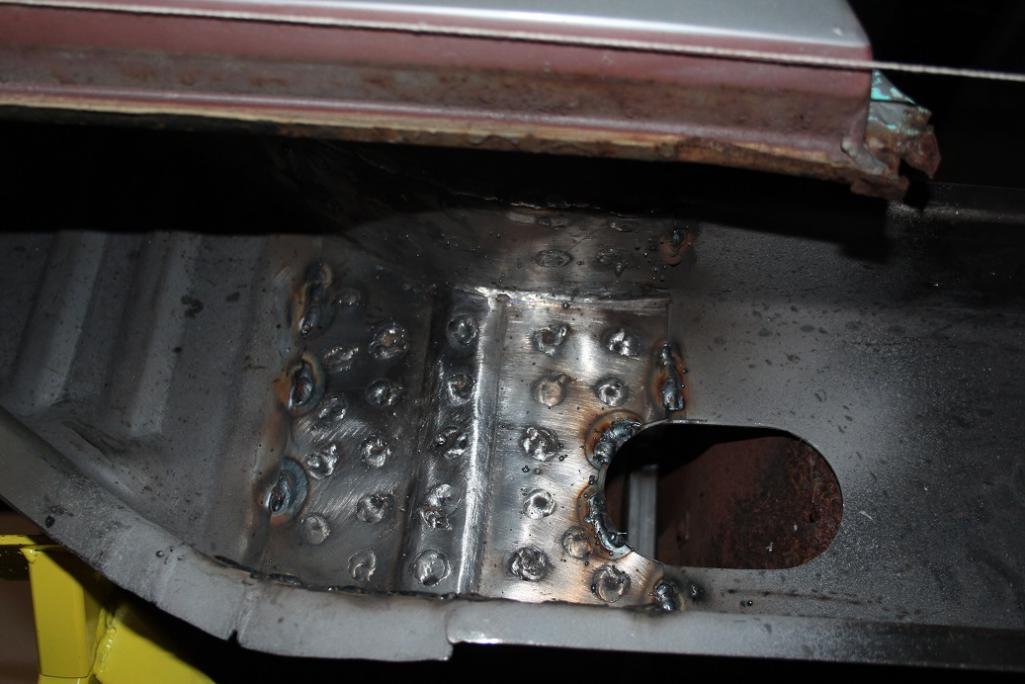
Posted by: 914forme Jan 2 2017, 07:00 PM
Matthew, working it 12 ga. is a little  I like crazy so keep up the great work.
Posted by: SixerJ Jan 4 2017, 02:03 AM
How did I miss this great thread before now, subscribed! ![popcorn[1].gif](style_emoticons/default/popcorn[1].gif)
Posted by: amfab Jan 4 2017, 10:18 PM
I am about a month behind you...
http://www.914world.com/bbs2/index.php?showtopic=301894
I hope my fabrications look this good.
Subscribed
-Andrew
Posted by: mbseto Jan 5 2017, 05:06 PM
Matthew, working it 12 ga. is a little
I like crazy so keep up the great work. Well, that got me thinking... Had to go back and measure. The sleeve is 14 gauge, as is the upper long from RD- only the inner long is 12, bent by a local shop.
Posted by: mbseto Jan 5 2017, 05:14 PM
Building a motor mount.
Making a pattern...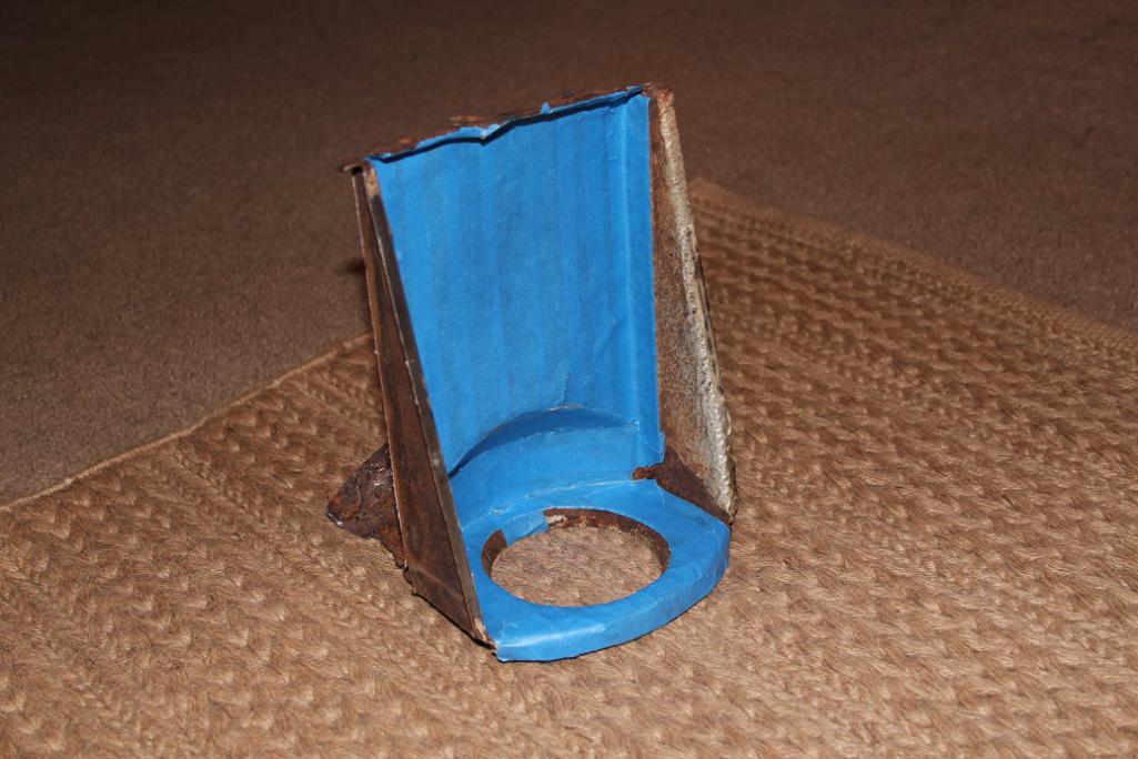
Cutting out the pieces...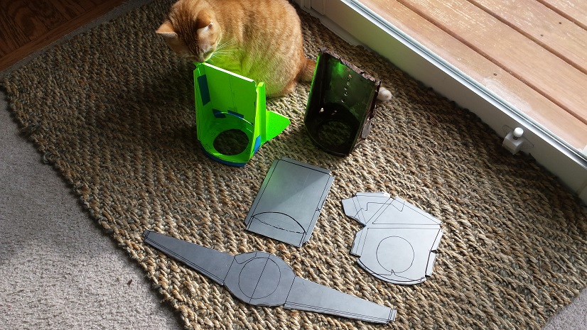
Hammer time...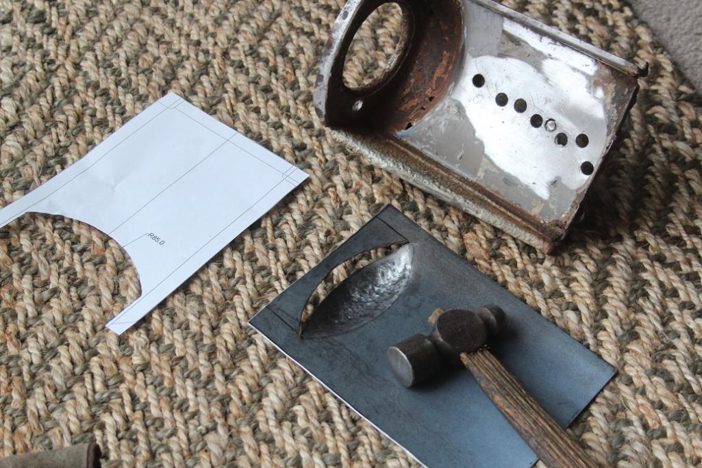
Posted by: mbseto Jan 5 2017, 05:22 PM
All the bits... These are actually the bits from the light gauge practice piece I made. Can't find a picture of the 14g stuff. Anyway, on to welding...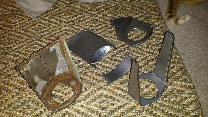
Welded together. I used weld through primer where there are flanges here. The bottom piece is just bolted to the main part of the bracket, I need to fit it to the long and to my dolly/jig and some bends may need a little tweaking. 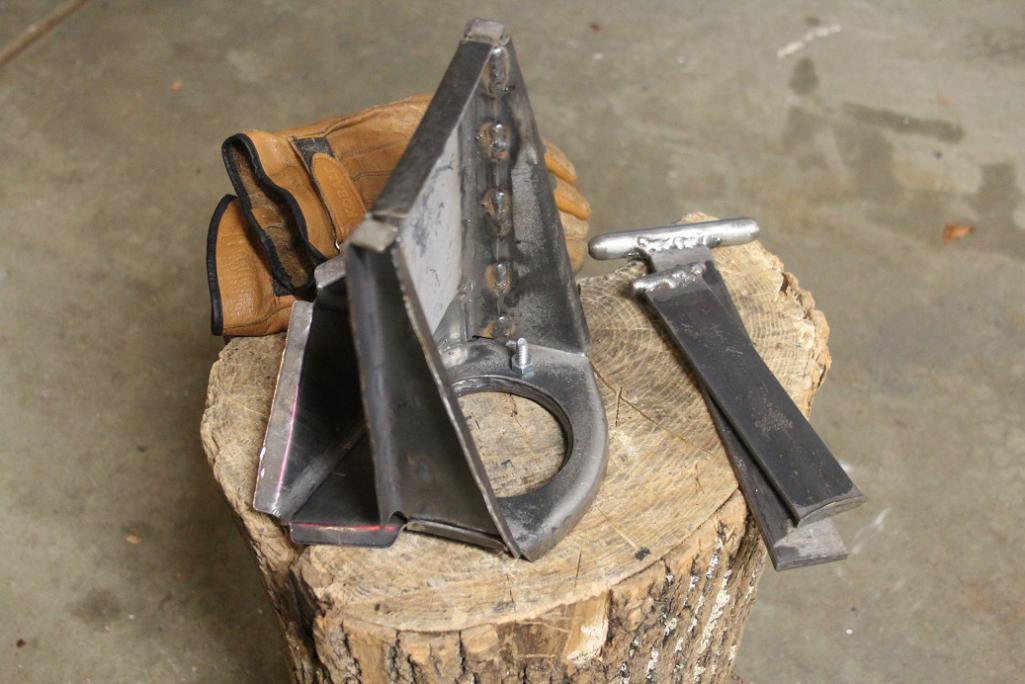
Posted by: 914forme Jan 5 2017, 05:40 PM
Nice work there 
Posted by: JoeDees Jan 5 2017, 06:10 PM
That...is...awesome!!!!
Posted by: amfab Jan 5 2017, 10:12 PM
Man, that is great
Matthew you have similar spots that I uncovered.
Having this thread has helped my anxiety about taking on too big a project.
Are you learning as you go or have you worked in sheetmetal before?
Posted by: mbseto Jan 6 2017, 08:00 AM
Are you learning as you go or have you worked in sheetmetal before?
Before I started on this car I would have said, oh yeah I've worked with sheet metal before. What I knew then feels pretty small compared to what I've been learning. So, yes, I am absolutely learning as I go. It's fun for me, and it's why I took on this project.
I often make a piece in a lighter gauge first, just to see how the metal is going to behave when I try to make that shape. I also spend some time on sheet metal forums, where they tend to show more about the actual making of a piece, whereas here most people just show the finished piece and then how it is patched in to the car.
Posted by: Cairo94507 Jan 6 2017, 08:19 AM
Wow! 
Posted by: amfab Jan 6 2017, 06:47 PM
Can you recommend a good Sheetmetal forum?
Posted by: tygaboy Jan 6 2017, 09:23 PM
Can you recommend a good Sheetmetal forum?
Some cool stuff here:
http://www.allmetalshaping.com/forumdisplay.php?f=20
Posted by: 914forme Jan 7 2017, 08:17 AM
Can you recommend a good Sheetmetal forum?
Not a Forum but this will lead you to things way deeper than you ever wanted
http://www.garagejournal.com/forum/showthread.php?t=182565 And it is relevant to work on our cars. Just wish he did not have so many large tools at his disposal. Robert does such a good job.
Posted by: mbseto Jan 7 2017, 10:41 AM
metalmeet.com is about my speed, there's guys there that know hammer-forming- I don't have any big sheet metal tools, have to make it work with hammers and dollys.
Posted by: Cupomeat Jan 7 2017, 11:23 AM
Wow, been a little lax on the 914world lately due to other life events, but this kind of thread really gets me excited!
Fantastic work here and I love that another 914 is getting a much longer life!

Posted by: cary Jan 23 2017, 05:40 AM
I am about a month behind you...
http://www.914world.com/bbs2/index.php?showtopic=301894
I hope my fabrications look this good.
Subscribed
-Andrew
I've been so busy with my projects that I haven't been keeping up with any other build/restoration threads. Both of you guys are doing some impressive work. I can feel the passion all way up here in PDX.
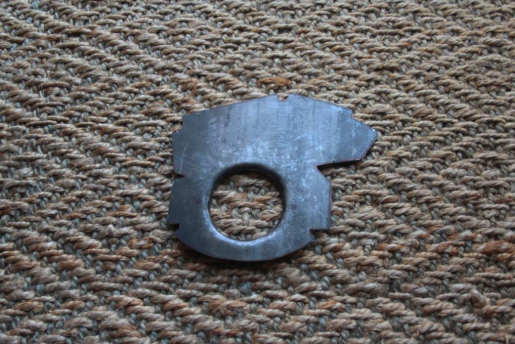
mbseto, love the motor mount creation. Did you have the big hole die cut ? Looks like it was made with a dimple die.
Posted by: Curbandgutter Feb 13 2017, 01:43 PM
MBSETO Man you are awesome. Love your work. 
Posted by: mbseto Jun 25 2017, 09:16 AM
Thanks for the encouragement, guys...
mbseto, love the motor mount creation. Did you have the big hole die cut ? Looks like it was made with a dimple die.
I roughed-sawed the hole, then turned the lip down with a hammer and T-dolly, then ground the edge flat. I was sitting over my dolly with a hammer in one hand and the rubber motor mount piece in the other to get that hole to a good fit. I scrapped one piece trying to get it right...
Posted by: mbseto Jun 25 2017, 09:52 AM
Need an update, Spring got away from me- work, etc. Got some garage work done, but it just didn't feel like enough and I put off posting. Here's a little catch up...
These dang spring clips... Someone suggested that I cut the ones out of my bad long and just weld them into the new long. Problem being that two of them were completely gone, rusted away entirely- just sad little stumps.
They look like they would be easy to make, but as I'm checking out the one remaining one, I see it is spring tempered. I have a buddy with a forge and talked to him about making these... cave-man garage work.
Made the pieces out of basic cold-rolled, there's the one remaining clip from what's left of the original long: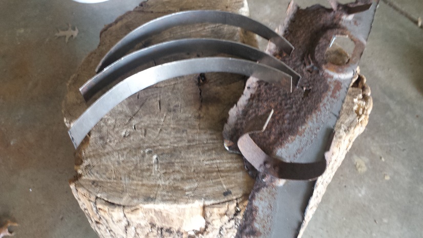
Here's the clips, cut and shaped but not yet tempered. If you squeeze them a little, they just stay bent, they are not springy at all.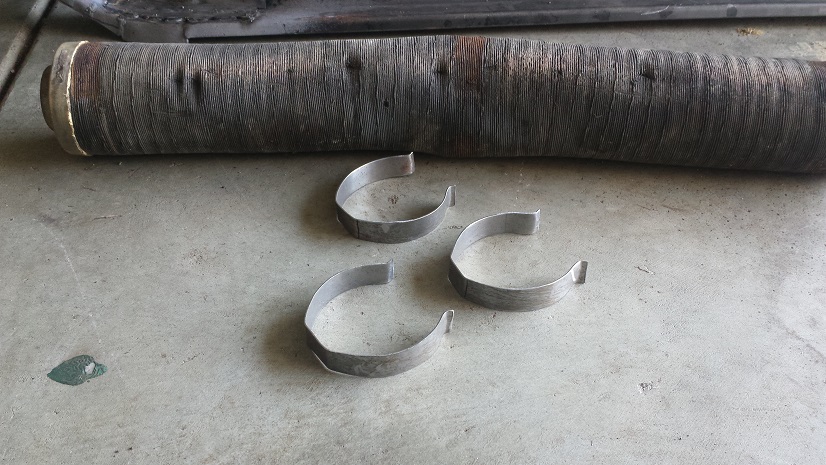
Into the forge they go. Heated to cherry, quenched in old motor oil: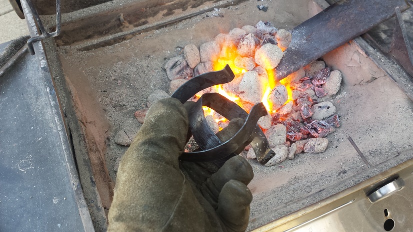
The annealing process, per an old book I have, says burn off the oil, then dip in oil again and burn it off again, then do that one more time and you have a spring temper.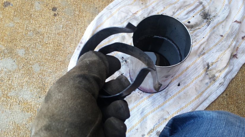
Worked like a charm, you can snap them and they vibrate like a tuning fork. Test fit everything with the tube, the long, and the elbows on either end. Hit them with a little weld-through primer and tacked them on.
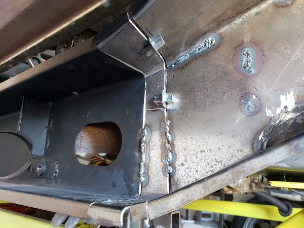
Posted by: mbseto Jun 25 2017, 10:03 AM
The new long is tacked in place. I keep measuring the door gaps over and over, I feel like a nervous mom. I'd be lying if I said I wasn't more than a little excited about this, it feels like a pretty big step forward. The next couple pieces from RD to close it up will go quick I think. Then we'll flip it around and do the other side. Less to do over there, but then it will have good bones again.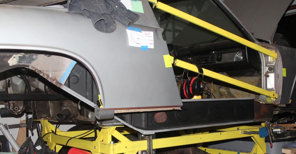
Posted by: amfab Jun 25 2017, 12:21 PM
The new long is tacked in place. I keep measuring the door gaps over and over, I feel like a nervous mom. I'd be lying if I said I wasn't more than a little excited about this, it feels like a pretty big step forward. The next couple pieces from RD to close it up will go quick I think. Then we'll flip it around and do the other side. Less to do over there, but then it will have good bones again.
Sweet, They look great,
Im about* to rivet mine on one side, maybe I will just tack them like that.
*"about" in 914 time means 2weeks—6 Months
Posted by: Garland Jun 25 2017, 01:57 PM
I was not sure how this build was going to go in the very begining.
Now I know for sure. Great workmanship.
Posted by: mbseto Oct 26 2017, 11:25 AM
Thank you for the encouragement. Being a part of the community really inspires my to up my game and try to maintain a quality of work...
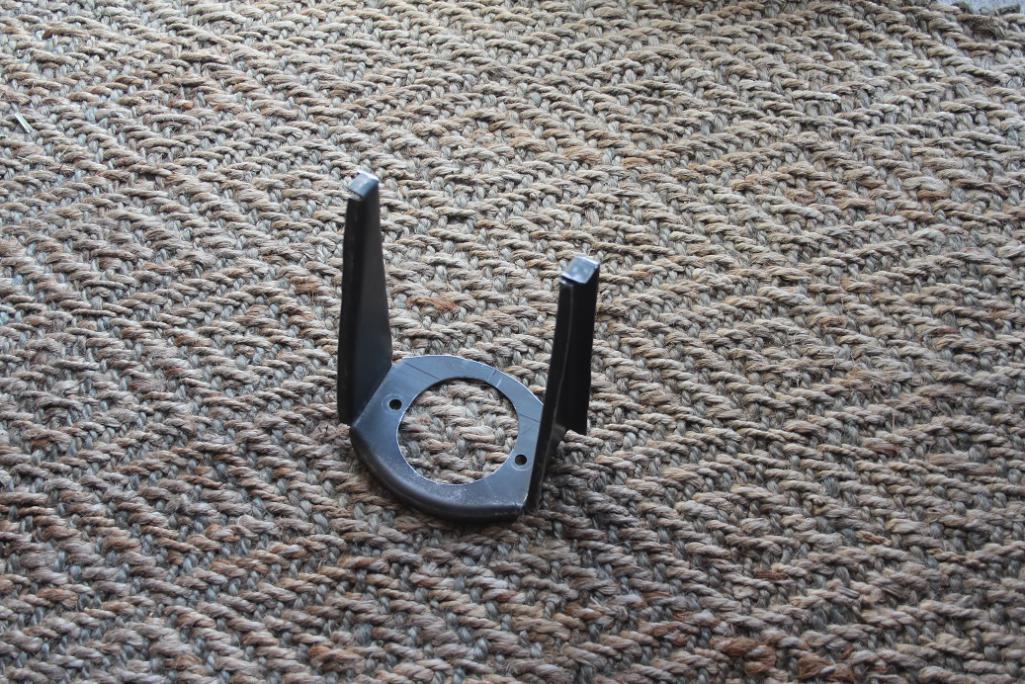
OK, so need some brackets to hold the heater pipes in place. Made a pattern and clipped them out: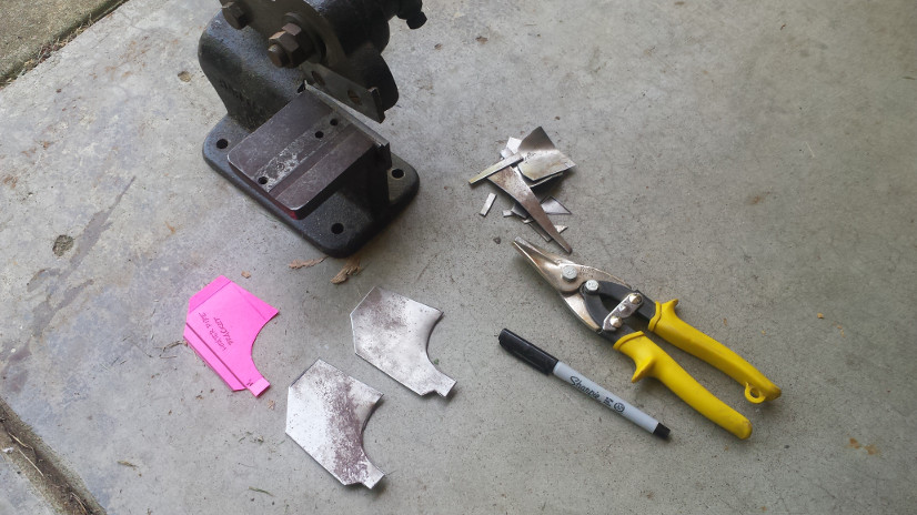
And here they are folded up: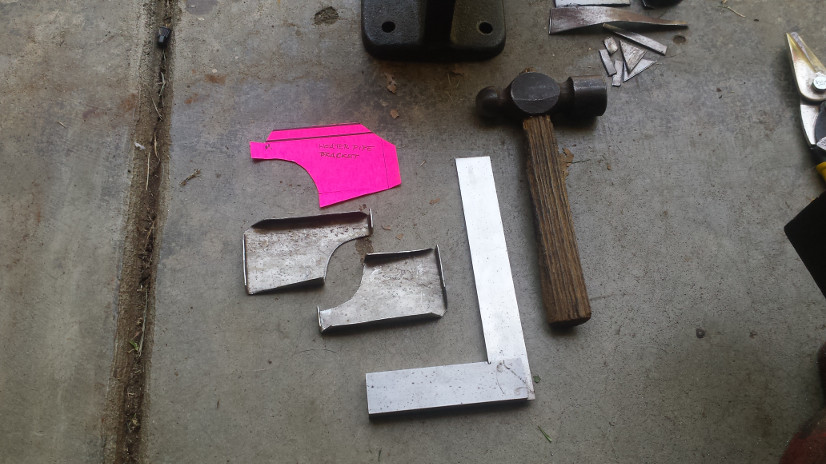
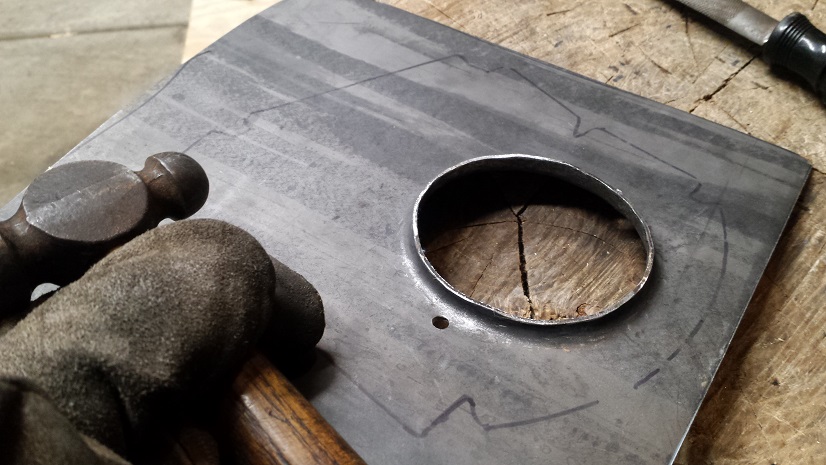
You know I got that extra-thick long welded in and then I was reading a thread about seat-belt bosses. Luckily it's not too late!! Ordered it from 914Rubber... It needs a fairly large hole in some 12g sheet to mount that thing; drill bit needs a 1/2" chuck. Can't use my hand drill, can't fit the 914 on the drill press. Called my vintage-tool-enthusiast buddy, he loaned me this wrist-breaker: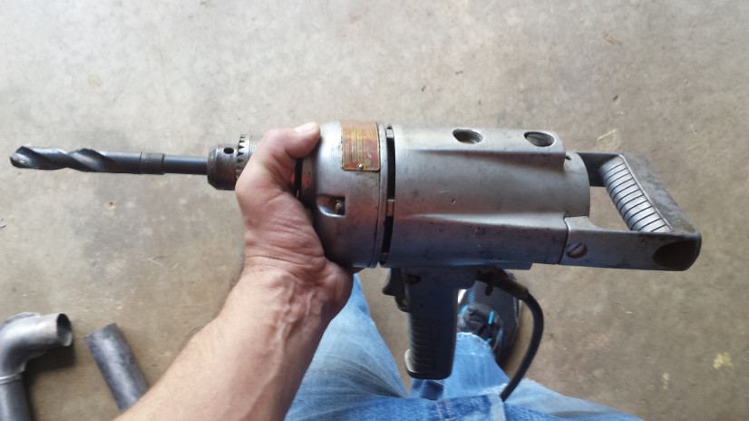
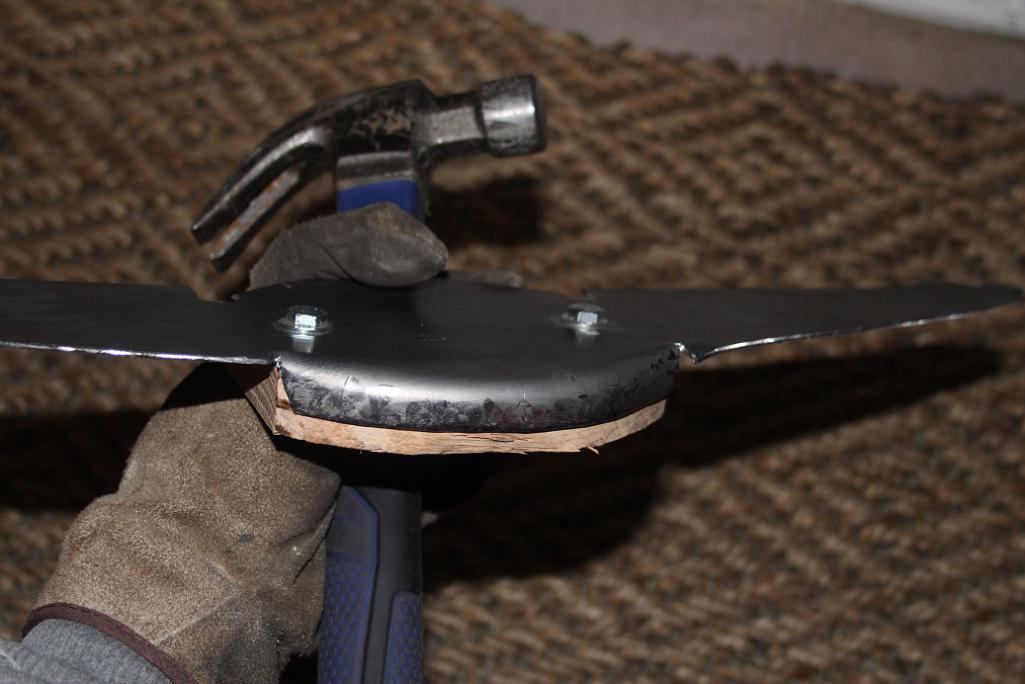
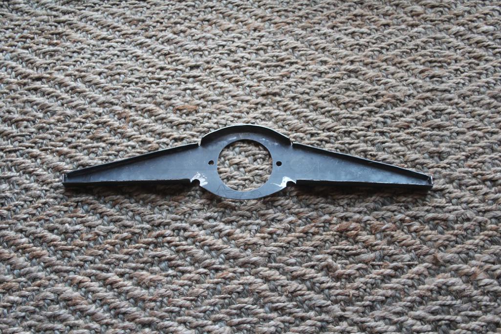
Posted by: mbseto Oct 26 2017, 11:36 AM
Another thread I was reading was talking about how much additional strength comes from the jack post. I was planning on leaving that off, and since my longs are well reinforced I thought it still might be OK. But in the end, I figured I'll take more strength wherever I can get it and since I still have the stock jack, might as well rebuild the jack posts.
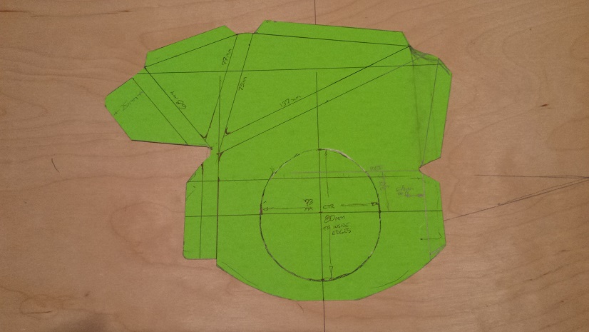
Made a pattern from the old one, snipped out the metal: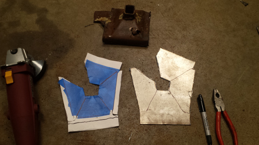
Hammer time: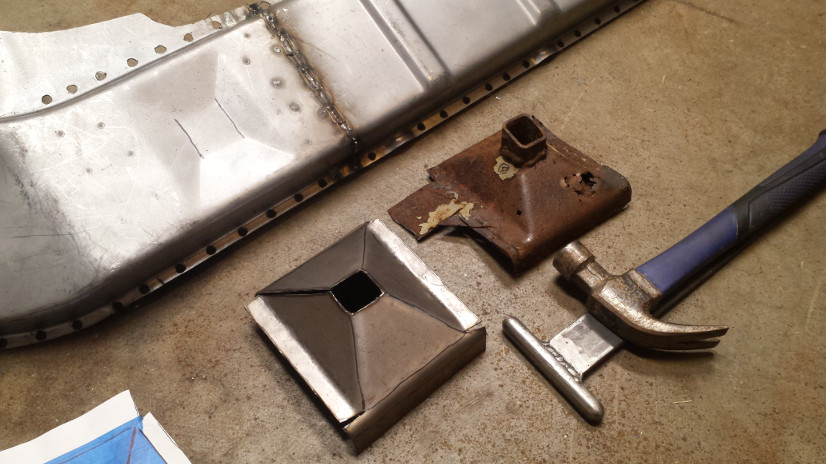
Got some square tube from the local metal supplier, kit needed some adjustment when all was said and done: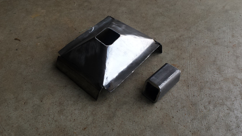
You don't see it here but I used the valance to position this guy: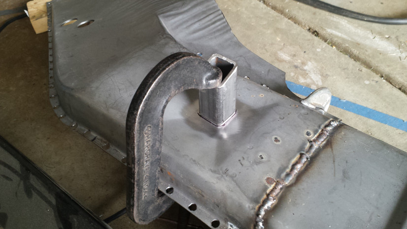
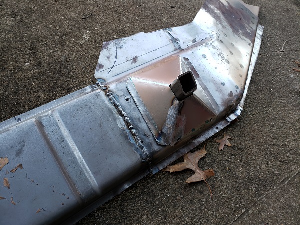
Needed to make some adjustments to the hole in the middle, ultimately a tiny bit of patch metal has to go in. I'll adjust the pattern before doing the other side. Some tapping with the hammer to get the flanges to conform to the long, then drilled for the rosette welds and primed- switched to the copper based weld-through, it does seem to weld easier: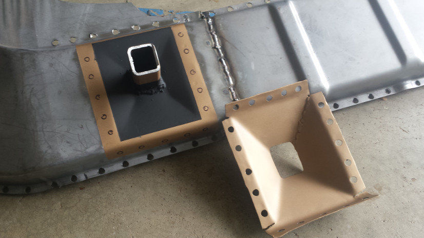
Posted by: bbrock Oct 26 2017, 11:47 AM
Man you do pretty work! 
Posted by: mbseto Feb 25 2018, 11:43 PM
These pics should have gone in with the last post, playing a little catch up here...
This is the heater tube in place: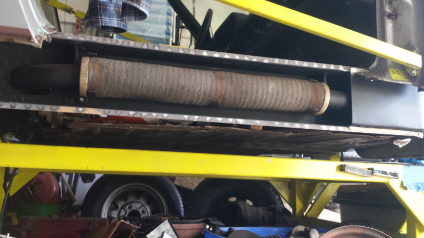
And the outer section of the long ready to go in: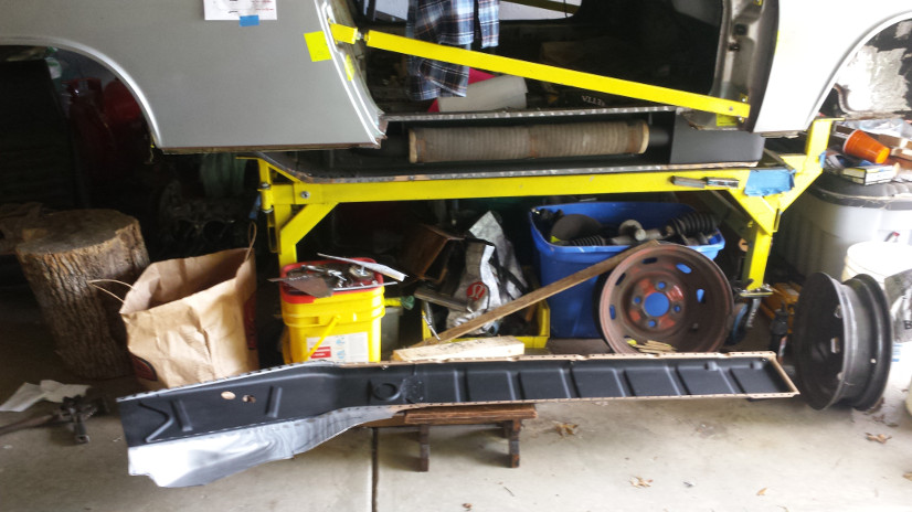
Posted by: defianty Feb 26 2018, 02:42 AM
Nice work you're doing there.
Posted by: mbseto Feb 26 2018, 10:46 PM
Nice work you're doing there.
Thank you, I am having a ball doing it. But my desire to be able to drive it is getting stronger and stronger...
Still doing a little retro posting... The wheelhouse had a rusty section above the long. Cut it out and fabricated a patch. Lots of tippy-taps with the hammer to get the edges matched up.
Here it is tacked in:
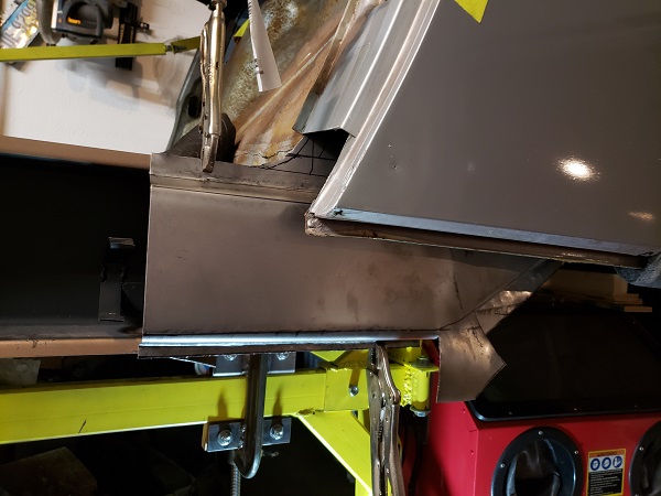
I should have detailed this part a little better, fitting the wheelhouse long at the back end. I cut out a layer of the "third" fire wall to get the long all the way up against the rear-most layer.
Made some tabs to connect the aft end of the long, then put the original piece back in place. There was a lot of head scratching here, a little bit of grinding off the welds and re-adjusting. Wasn't thinking much about taking pictures, but looking back on it, the thoughts in my head were a lot more complicated than what actually ended up happening.
Attached image(s)
Posted by: mbseto Feb 26 2018, 11:15 PM
Took out a little of the door frame to get those rosettes in there. Wasn't really sure until this point whether I could get the long replaced without cutting the fender. Glad I took Rick's advice.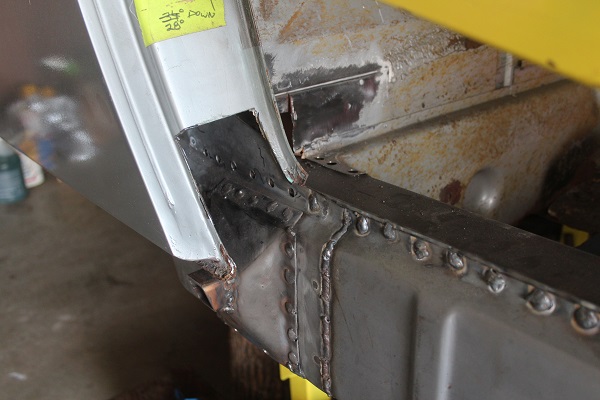
Need to replace the bottom of the door post. The PO just slapped a plate on there. I looked through several threads for this, everyone has a different name for it: door post, torque box, hinge post base... Whatever it is, cut a pattern: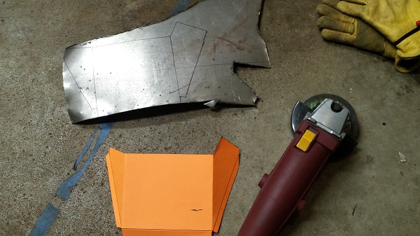
Here's another little piece that was cut away to access the rosettes at the front of the long: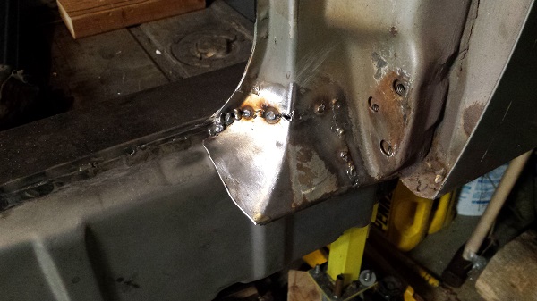
Bent the hinge post base to shape and trimmed to fit: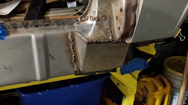
Blew some holes trying to mate the original metal to the new metal. Didn't really want to post this pic but sometimes your purpose is to serve as a warning to others I guess.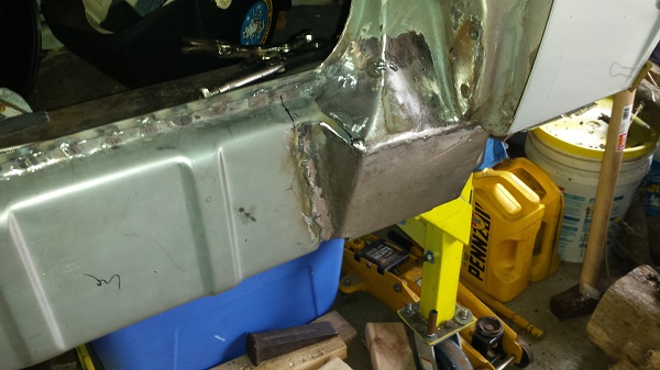
Pondered over that for a bit and decided that putting in a single piece with a little overhead welding is better than two tiny patches.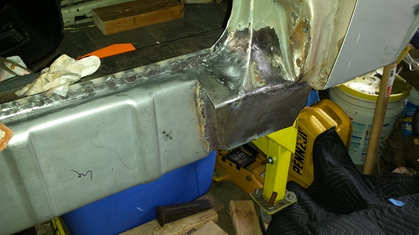
And finally the sill is tacked in place. This gets me up to today and I was surprised at how good it felt just to get the sill back on. You may notice the door braces are gone from this side. After getting the long completely welded in place, but before starting on the door port and sill, I took them up and brought the door up from the basement and held it in place. It looked about like I had hoped, no gross errors anyway. I know the car will settle once it is back on its feet, hopefully the gaps stay good.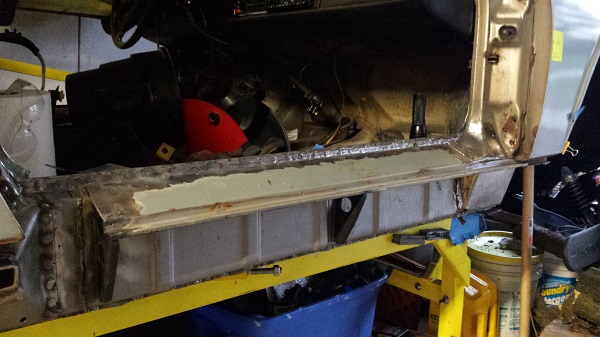
Posted by: bbrock Feb 27 2018, 09:07 AM
I'm really impressed with your work. Keep 'em coming!
Nice work rebuilding that post bottom from scratch. Can't quite tell, but did you leave drainage holes at the bottom?
Posted by: Mueller Feb 27 2018, 09:27 AM
Bookmarking thread, great visual tutorial on some repairs I need to do.
Posted by: mbseto Feb 27 2018, 12:46 PM
I'm really impressed with your work. Keep 'em coming!
Nice work rebuilding that post bottom from scratch. Can't quite tell, but did you leave drainage holes at the bottom?
Thank you! Yes, the long had indentations for drain holes already and the piece I added runs straight over them to leave a hole. I scalloped it a little at those points as well.
Posted by: mbseto May 19 2018, 09:09 PM
Just to finish up the last post, this is the sill tacked, welded and ground down.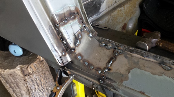
Not perfect, but glad to get it back on. I may go back and try to touch it up a little later. Sometimes I mess with it too much when I should leave it alone.
Posted by: mbseto May 19 2018, 09:18 PM
This brings me to a milestone... The passenger long is completely replaced. Still need to get the suspension pylons and install them and also the engine tray, but I'll be flipping her around to get the driver's long done.
Glad I followed Rick's advice and did not cut the fender. Wasn't sure it would work, but it did.
Pulled all the parts boxes out of the way and rolled her out of the garage. Swept the floor and flipped her around and back in.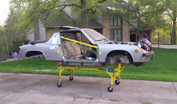
Posted by: mbseto May 19 2018, 11:10 PM
Shifting back into destructo-mode to remove the old long. Here's the before: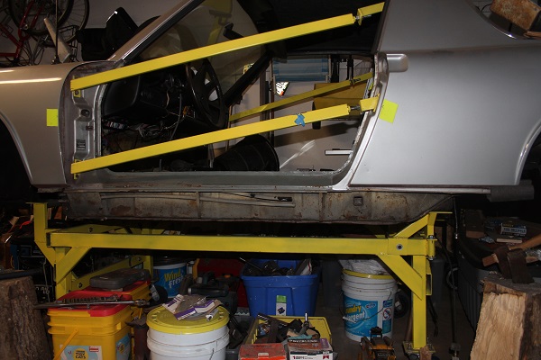
Here's the carnage. Good view of all the previous repair work.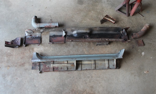
Looks like the hole for the seatbelt boss was made with a .45: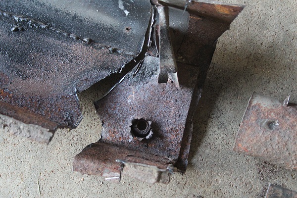
E-brake bosses: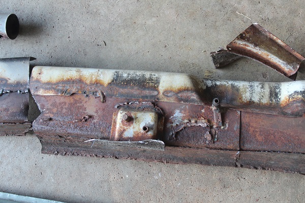
Saving the heater tube. A lot of this looks like it was brazed together: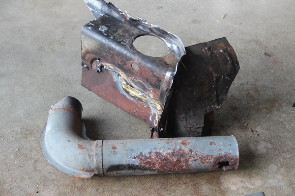
After the experience of the passenger side long, I cut this side with a hack saw because it has a very narrow kerf, and cut high up on the ends. I should be able to get this sill back on in one piece. 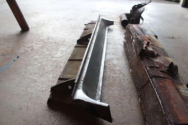
Cut ends, forward and aft.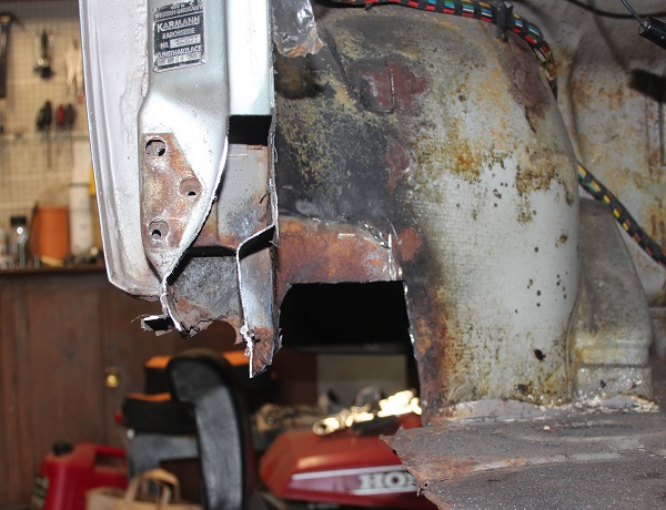
That little bit of newspaper up there came from another mouse nest in the driver's side suspension console. Must be an ideal spot. Maybe this is where they put the mother-in-law. I guess that console is going to be filled with sunflower seeds, too.
Posted by: jmitro May 20 2018, 07:06 AM
LOL
man that is some serious surgery! nice work
Posted by: mbseto Jun 4 2018, 09:55 PM
man that is some serious surgery! nice work
Thank you. Dealing with the passenger side made me bold...
Posted by: mbseto Jun 8 2018, 07:05 AM
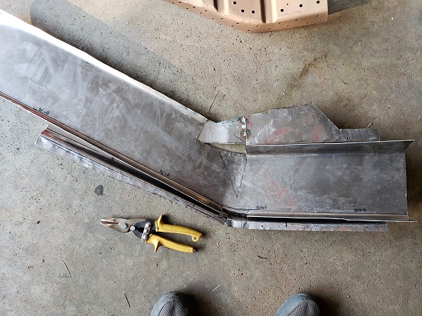
Temporarily switched from destructo-mode to fab mode to gin up the rear corner of the wheel well that extends back under the door post and between the halves of the long.
Cut a rectangle and bent the edge profile: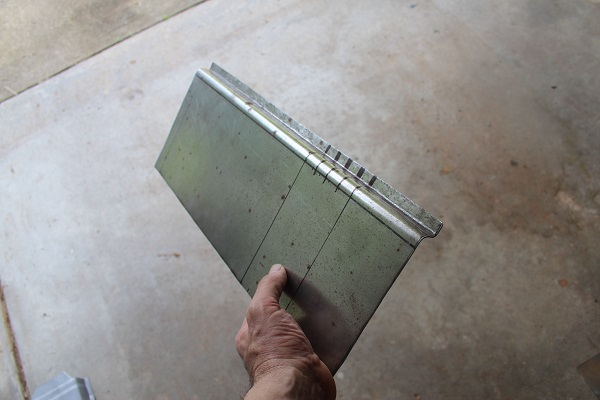
Checking the profile against the outer long piece: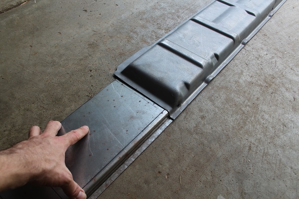
Bending the contour around the inner long piece: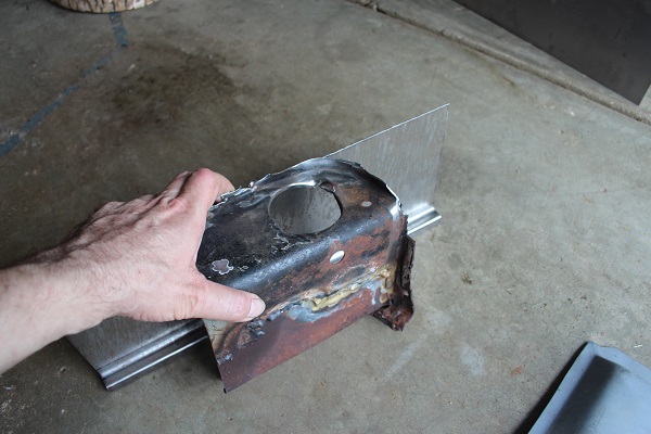
Mise en place: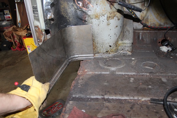
Posted by: bbrock Jun 8 2018, 07:12 AM
That there is some fine work! I know how difficult getting that bend around the front of the inner is to accomplish. 
Posted by: Dion Jun 8 2018, 02:59 PM
Brilliant stuff here Matthew. I’ll certainly be borrowing your ideas on the heater tube hole in the long when I do my drivers side. Really like the templates you made.
Keep it coming!
Posted by: mbseto Jun 19 2018, 10:56 PM
I suppose this guy's best laid schemes went agley many years ago...
https://www.youtube.com/watch?v=fnEi0LrQ-WQ
Shop vac'd him out with a custom attachment: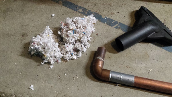
Posted by: mbseto Jun 19 2018, 11:06 PM
I posted a question in its own thread looking for opinions on whether any of the long can be saved. I'll not belabor it here, but with the help of a few others here, convinced myself to cut the whole thing out and replace with RD metal.
Looking into the upper driver's side long: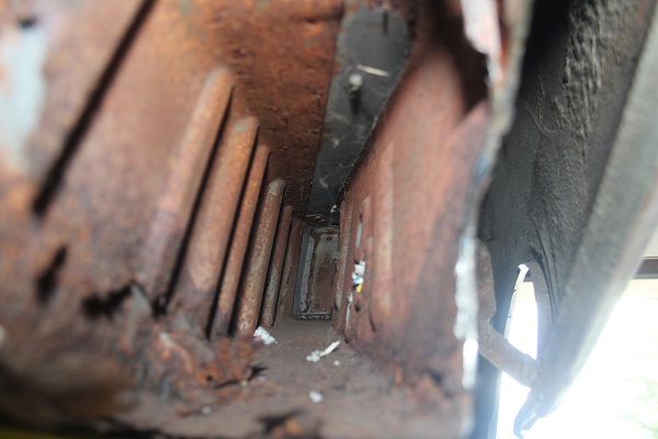
Level of the rot. It almost looks like this car was sitting in water at one point. The common saw is "rots from the inside out", but this seems to be from the bottom up: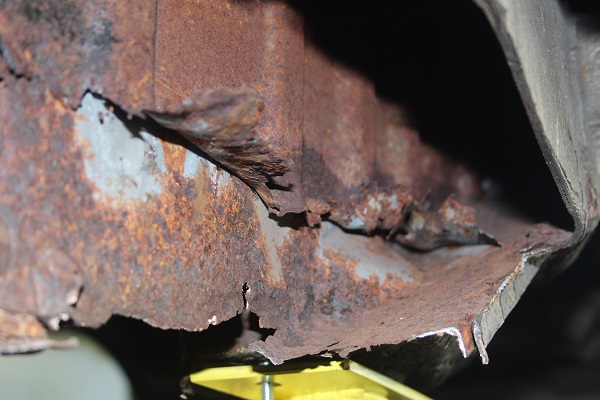
Took of the engine mount to get access a little further up and also just wanted to see behind it. The mount on the left is the driver's side, the right is the pass side for comparison. Pass side is scrap, but I think the driver's side will clean up OK.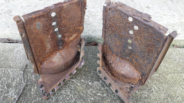
Posted by: bbrock Jun 19 2018, 11:12 PM
That nest looks so well preserved I kept expecting to see a mouse head pop into view.
Looking forward to watching the long replacement. 
Posted by: mbseto Jun 19 2018, 11:21 PM
Here's some borescope pics. Not the greatest quality, but if you want to see what you can get from a $20 borescope attached to a smartphone, here you go. First, the suspension consoles after a little cleanup work. Nowhere near as bad as the passenger side, but the streak of rust is a little concerning...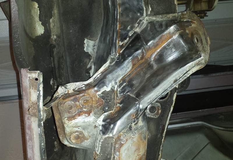
This is inside the outer console looking at the bolt tubes, this is where the mouse nest used to be: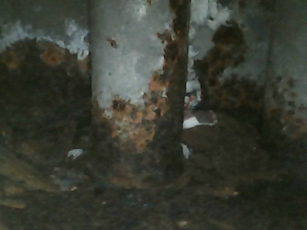
And another. Large flaked-off rust visible here.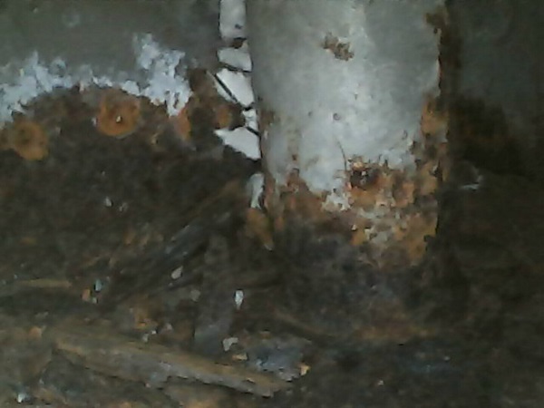
This is inside the inner console, looking straight down into the grooves formed by the thick reinforcement pieces: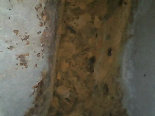
I could probably convince myself that these are structurally sound, but in the end I think I want both sides to be at the same level of restoration, if that makes any sense.
Posted by: mbseto Mar 24 2019, 09:18 PM
Can't believe it's been so long since my last post. Busy fall and winter, got work on the car done incrementally. Time to catch y'all up... I guess I knew this at one point, but after cutting all the rust out of the driver's side long, I realized I was going to be fabbing more than I did on the other side. I suppose that's why I started this project in the first place.
So after removing the engine support and suspension pylon, then peeling back the rusted layers, I figured I would build a buck and hammer form the "elbow" shape where the long comes out of the wheel well and turns horizontal...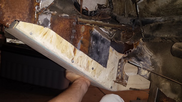
I thought I would impress everyone with a gif of me forming this part. The gif turned out good, but the part is no bueno. 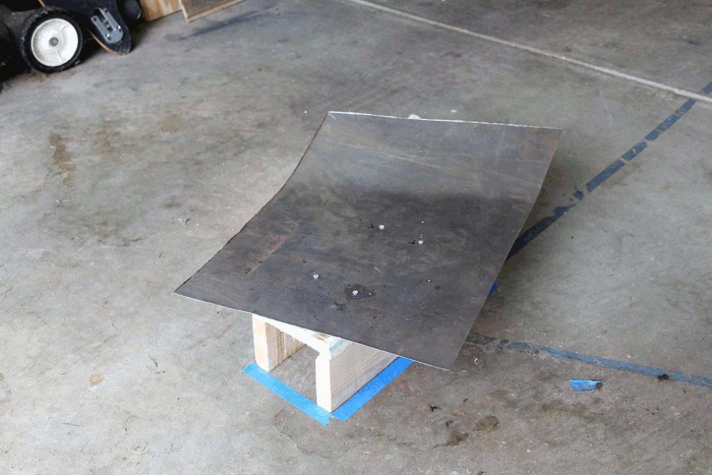
Here's the final - not usable. In the end, I just made the part as a straight channel section, then slitted it and bent as needed. Slits get welded shut. A couple transition pieces will be cut to fit and added for the final attachment to the horizontal part of the long.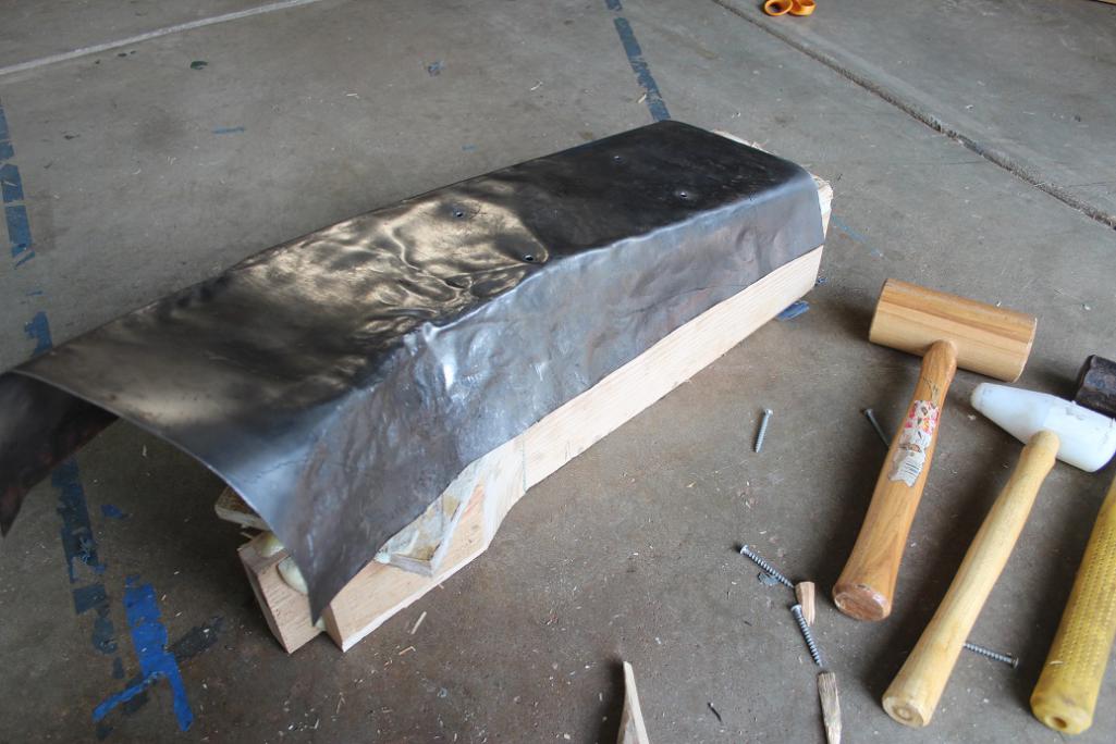
Posted by: mbseto Mar 24 2019, 09:27 PM
Made a buck to form the inner corrugated layer. This is going to be a weld-up of three pieces. Trying to strategize here so that the welds on the inner layer go one direction and the welds on the outer layer go the other direction. I.e. they are never parallel.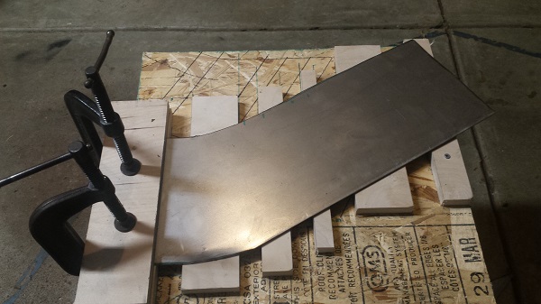
So here's the inner piece. If you want inner piece, you have to make it yourself. Wisdom for our time.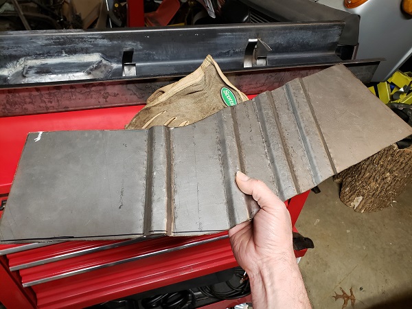
We'll come back to this, I'll be making the sides of it to fit - after the outer layer is all welded up.
Posted by: mbseto Mar 24 2019, 09:49 PM
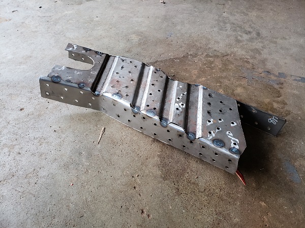
You might remember from way back, I had a couple long blanks made up from 12 gauge, so they would have the combined thickness of the stock piece plus the stiffening kit in a single layer. So one additional task for the driver's side is to create the e-brake pocket.
Marking the position next to the original: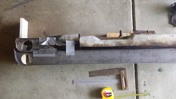
Marked out the shape of the pocket and started cutting...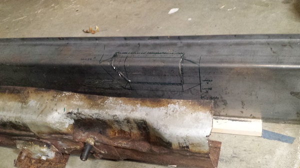
Trimmed the cut piece down and then tacked it back on. Just trying to be efficient here. Layed masking tape over the gap to make a pattern.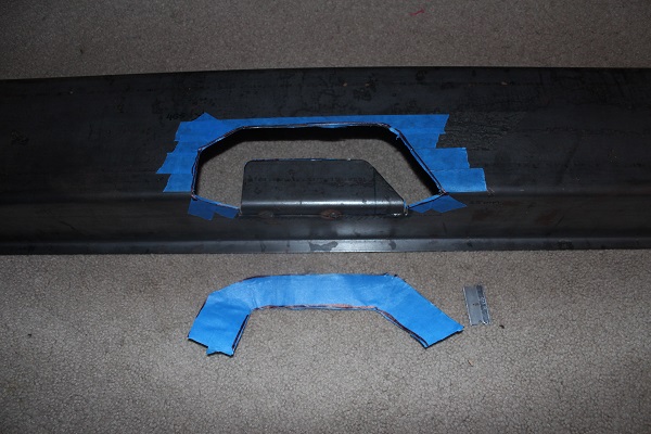
Made the patch piece from the pattern and bent it. Little fine tuning with the grinding wheel to match it up and bevel the edges to weld.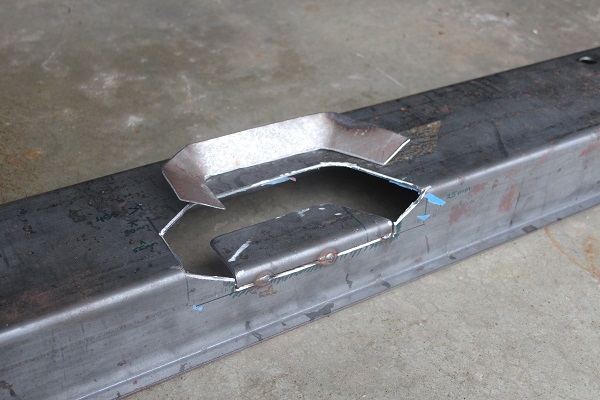
Final pocket, dressed up a little.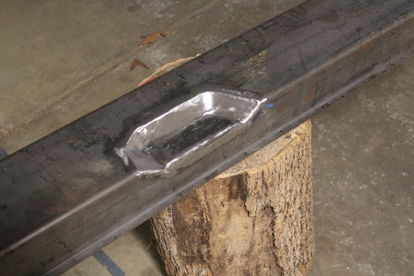
Posted by: mbseto Mar 24 2019, 09:56 PM
So here's the driver's side long, all kitted up. I made all of it except the obvious Restoration Design piece and the tubes. You can see my final version of the inner long on the right - after rejecting my hammer-form attempt.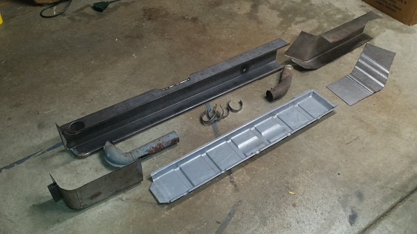
That should do for some Monday morning reading. Still have a couple posts before it's all caught up. I'll try to get to it in the next day or two.
Posted by: bbrock Mar 24 2019, 10:03 PM
I thought I would impress everyone with a gif of me forming this part. The gif turned out good, but the part is no bueno.
Thanks for the update! I went through a similar exercise on that elbow piece and wound up doing the same. I think you made a better run at it though with that buck.
We'll come back to this, I'll be making the sides of it to fit - after the outer layer is all welded up.
That sir, is impressive!
Posted by: tygaboy Mar 25 2019, 07:56 AM
It's Hammer time! Way to go on making your own parts. Damn impressive.
You look like you're really enjoying yourself with all the fab work.
It's very motivational so please keep the pics coming!
Posted by: amfab Mar 25 2019, 09:17 AM
It's Hammer time! Way to go on making your own parts. Damn impressive.
You look like you're really enjoying yourself with all the fab work.
It's very motivational so please keep the pics coming!
I tried to make a patch for that piece so I can attest to how difficult it is to get it right. I gave up and bought the outer/inner. You are a better man than I sir!
-Andrew
Posted by: mbseto Apr 16 2020, 08:00 PM
Good grief, it's been a year since I posted on my build thread. Last post was the eve of my 49th birthday. What happened? My wife and I decided to try to expand her business a while back. Four years of effort came to fruition and we began building last winter. It required all of my attention and it was quite a roller coaster. New location was opened in September of 2019. Of course that ended up being another tidal wave of activity. Friends kept asking, hey now you're open, nice to sit back and rest finally, eh? Glrb. Got an augmented staff trained up, and well my wife is a force of nature, and slowly I started sneaking back into the garage. Just in time for a global pandemic. Spent this birthday quarantined on a cold concrete floor with a welding gun in one hand and a whiskey bottle in the other. Not half bad, really. Here come the pics...
Posted by: mbseto Apr 16 2020, 08:08 PM
So where the heck did we leave off? Prepping the driver's side long... Looks like I can salvage a heater tube, just need to patch the end of it.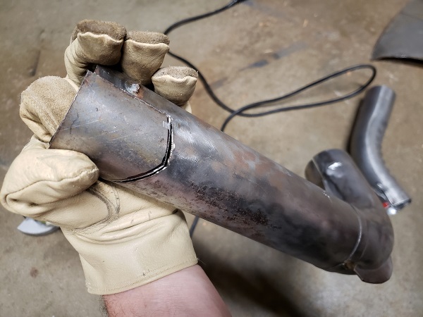
This is the new long with all the little bits welded in. Same drill as the passenger side, so I didn't take many pics, but to recap, made new brackets for the heater tube, made new spring clips for the heater tube (once again, my buddy with the forge helped my heat treat them to a springy consistency), welded it all in place. New seat belt boss is in there, too.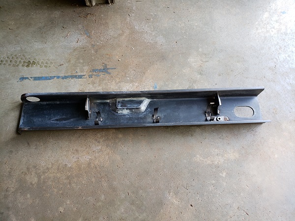
Here it is with a coat of primer and weld-thru on the flanges.
Posted by: mbseto Apr 16 2020, 08:20 PM
A little more blood and gore. The crime scene from the outer long is above, here's the inner. Had to dig into these layers, find out where the rust ends and fair metal begins.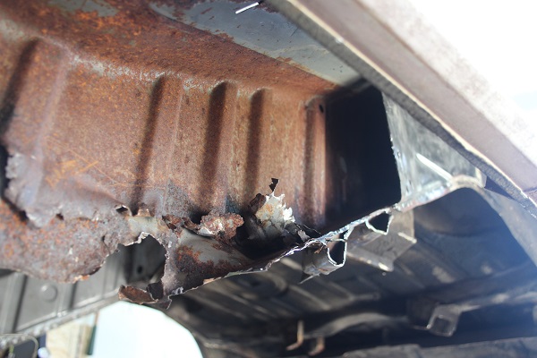
Worked in to where I was happy and tried to pick cut lines where I'b be OK welding. Not shown here is peeling back and extra couple inches of the inner layer so that the welds of the two layers would not be right over each other. There will be a decent pic of that later.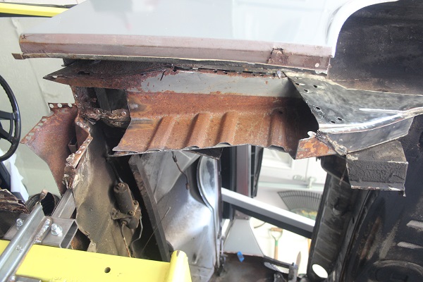
Looking up into the long, no other surprises. We'll spray something up in there before we seal it up. Ospho, then some primer.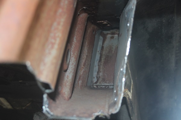
Out with the old...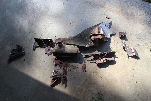
This is a nasty looking long. I'll stand this up against anything in anyone's hall of shame. Good riddance.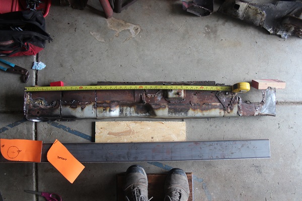
Posted by: mbseto Apr 16 2020, 08:29 PM
Agonized a bit over whether the old engine mount was still good or if I should fab this side. Cleaned it up good - some pitting in there - decided to run with it.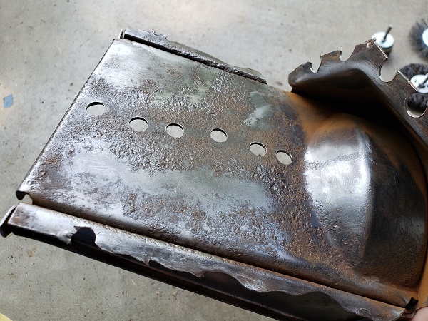
Primer and weld-thru on the mount and also on the long.
I tacked it in place and don't have any pics. I do hope I remember at some point it is only tacked... Also notice this last pic shows my fabbed piece in place and I don't have any pics of that going in. You get the idea, though.
Posted by: Dion Apr 16 2020, 08:30 PM
Just brilliant work! Way to go Matthew.
Attached image(s)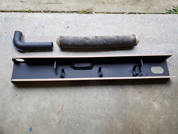
Posted by: mbseto Apr 16 2020, 08:44 PM
Tacked the inner long in place and scratched my head over how to deal with this gap. I made a couple attempts to try to make these two meet nicely. One of my guiding principles in fabricating is to try to make a thing as one piece if I can with as little welding as possible. As this project draws out, I have another little voice asking me, do you ever want to drive this thing? Yes, I do.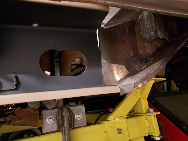
Here's working out the solution. I am posting pictures from months ago and now I find it does not itch my brain so much as it did at the time. 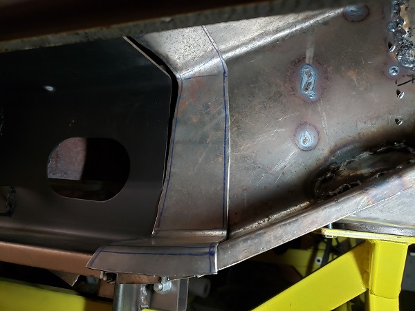
Posted by: mbseto Apr 16 2020, 08:57 PM
Need to pattern up a sleeve to join the sections of the long. I actually fabricated the ribbed piece a few posts back (last year!! ) so this pattern just guides how to trim it and how to make the sides.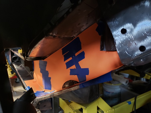
Cut the pieces up, pushed them around a little and pre-drilled the rosettes. 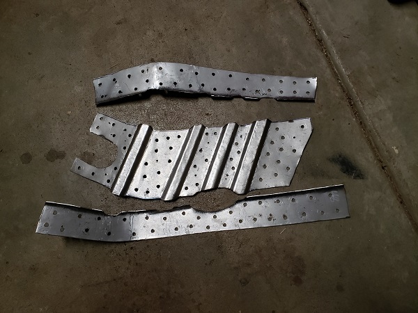
What you don't see is the constant test fitting and grinding edges to get them to fit nicely. Aside from it being much easier to drill the holes before it is welded up, I was also able to see how close the sleeve layers lay against the outer layer and mach sure it is line-to-line. This is final fit and tacking them together.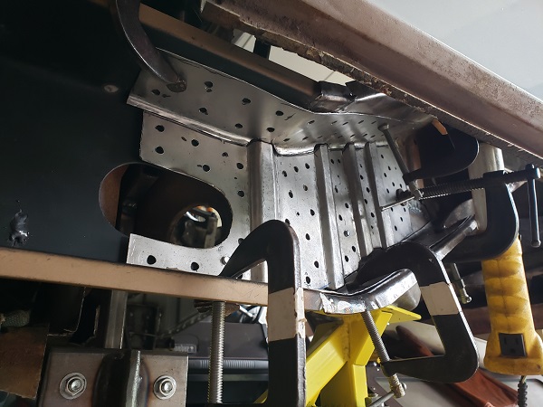
Nice to weld this together sitting in the middle of the garage floor instead of hunkered up in the wheel well or something. Added a little corner in there with the last rib in the line, also a piece to cover the bulge of the engine mount.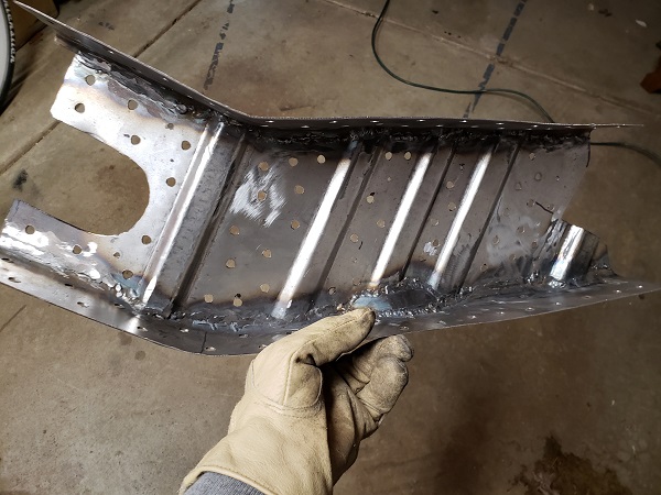
Posted by: tygaboy Apr 16 2020, 09:58 PM
That is great looking work. Very. Nice. Fit. And I know what a pain it is to get things to that point! Again, great, great work.
Posted by: jaredmcginness Apr 27 2020, 01:21 PM
Holy smokes.
I just found this thread from your signature. (Same year and motor as me, so I was intrigued.)
How I wish i had seen this before I started my long replacement. Goes to show if you really put the patience into this, it turns out beautifully.
Seriously top notch work.
Posted by: Mueller Apr 27 2020, 01:54 PM
Very inspirational and tons of great fab work and ideas.
Posted by: dereknlee May 26 2020, 06:12 PM
Matthew,
Holy crap! Your fabrication skills are amazing.  That home made sheet metal brake is clever, bookmarked.
Inspiring stuff, keep it up!
-Derek
Posted by: Krieger May 26 2020, 06:46 PM
Wow! That's a lot of really good work!
Posted by: mbseto Aug 1 2020, 01:43 PM
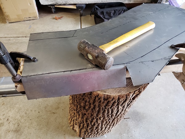
Sometimes it feels like everything is a jury-rig. Guess what this is going to be? Making it out of 12-gauge so I will not need to weld the stiffening kit over it. Was worried that my hammer-forming abilities would not be up to it, but the whole "bigger hammer" thing seems to be working.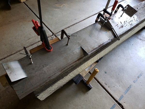
More updates coming - had a piece that was giving me trouble but I think I've worked through it. Stay tuned.
Posted by: mbseto Aug 18 2020, 10:27 PM
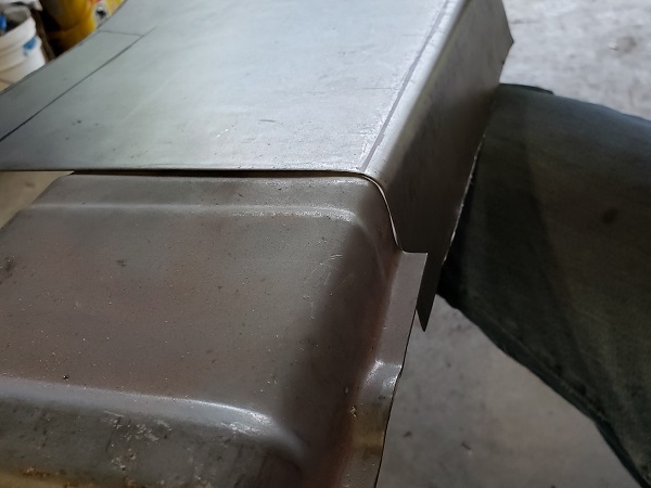
Photo assault to get the thread caught up a little. Driver's side outer long, if you're following along, fabbing the piece that no one makes aft of the door.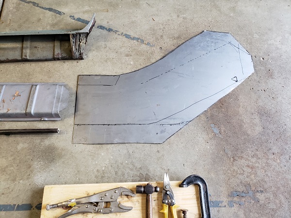
Posted by: mbseto Aug 18 2020, 10:30 PM
Posted by: mbseto Aug 18 2020, 10:33 PM
Got to this point and wasn't really happy with the fit. Cut a blank for attempt number 2...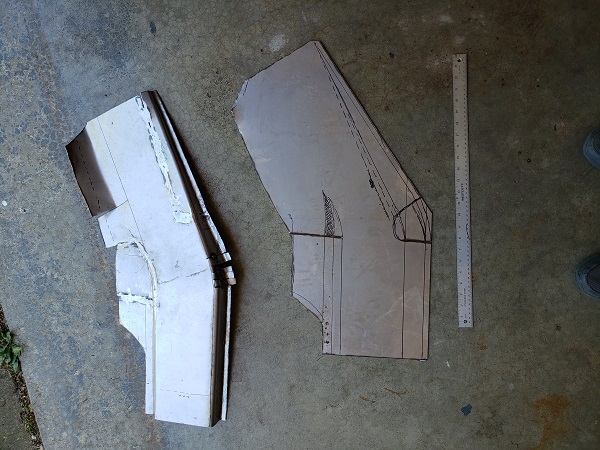
Here's the final fit I was OK with. See the #3 written on there?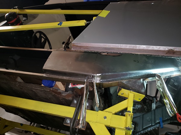
On deck: The inner layer for this piece...
Posted by: djway Aug 19 2020, 12:28 AM
Beautiful fab skills.
Does the stump have auto shrink?
Posted by: porschetub Aug 19 2020, 02:44 AM
Beautiful fab skills.
Does the stump have auto shrink?
 ,my first rustaration was a fairly rare one year only 66 Beetle,used pieces of hardwood to form parts and could custom fit parts shape with any common woodworking tools ,new floors and repaired rotten tunnel came out nice.
But you have to look @ what mbseto has hand formed ....
 excellent work.
Posted by: bbrock Aug 19 2020, 08:16 AM
Your fab skills continue to impress. Such nice work. It's a shame nobody is making that part though. Seems about half of these serious rustorations need it.
Posted by: Superhawk996 Aug 19 2020, 09:53 AM
I continue to be amazed at how nice some of these cars look at 20ft as shown on page 1 but how rotted they really are.
Mine was exactly the same.
Great fab work
Posted by: mbseto Aug 19 2020, 10:58 PM
@http://www.914world.com/bbs2/index.php?showuser=22428 - I was specifically looking for one where the welding would all be inside and not visible. I got that, and I got it in spades!
Posted by: mbseto Aug 19 2020, 11:14 PM
Does the stump have auto shrink?
@http://www.914world.com/bbs2/index.php?showuser=19266 , funny you should ask...
This is the inner layer, nested in the outer layer that I made above. You can see the angle isn't quite right. These pieces that angle both upward and inward - I tend to underestimate it in the layout. Of course I probably shouldn't rely on estimation at all... Anyway, a little shrinking might save it...
Grabbed the tucking fork and put one good tuck in the bottom of the elbow. Threw it on the stump and hammered it out.
Just about right - a better man might've chased out the wrinkles with a good planishing. This is buried so many layers deep in the long that I am not worried about it.
These are the two layers side-by-side. Cut a little piece to make that inside corner.
Posted by: Superhawk996 Aug 20 2020, 07:36 AM
Always love seeing a shrinking stump.
These are so effective it’s stupid! Someday I hope to have an Oak Stump about 4 foot diameter with various radius bowls within it!
No room right now . . . Someday!
Posted by: RAB914 Aug 20 2020, 09:48 AM
i have use a clam shell for make this part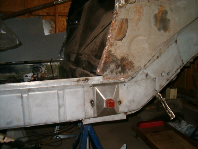
Posted by: djway Aug 20 2020, 06:44 PM
Does the stump have auto shrink?
@http://www.914world.com/bbs2/index.php?showuser=19266 , funny you should ask...
This is the inner layer, nested in the outer layer that I made above. You can see the angle isn't quite right. These pieces that angle both upward and inward - I tend to underestimate it in the layout. Of course I probably shouldn't rely on estimation at all... Anyway, a little shrinking might save it...
Grabbed the tucking fork and put one good tuck in the bottom of the elbow. Threw it on the stump and hammered it out.
Just about right - a better man might've chased out the wrinkles with a good planishing. This is buried so many layers deep in the long that I am not worried about it.
These are the two layers side-by-side. Cut a little piece to make that inside corner.
Cool. Ever since I saw my first Stump Shrink video I have really wanted one, and some hammers and some..........
Great work
Posted by: bbrock Aug 20 2020, 06:50 PM
If I'm not mistaken, that's a fine piece of ash you have there.

Posted by: mbseto Dec 14 2020, 11:59 AM
If I'm not mistaken, that's a fine piece of ash you have there.
@http://www.914world.com/bbs2/index.php?showuser=20845 exactly right and mum's the word!
Since the emerald ash borer appeared around here some years ago, people will pay you to haul it away. 2nd best type of firewood you can get.
Posted by: mbseto Dec 14 2020, 12:02 PM
Finished inner long: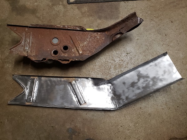
Posted by: mbseto Dec 14 2020, 12:05 PM
Here's the jack point. This is just fitment - I'm playing catchup here and I don't think I got pics of these primed on the insides for welding, but you know the drill. Rest assured, I am trying my best to protect this baby from the inside.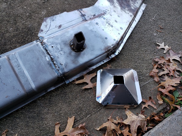
Posted by: mbseto Dec 14 2020, 12:26 PM
After doing the passenger side I thought I'd take some additional care on the driver's side to cut carefully and strategically to make the reassembly go easier. However, after carefully cutting out the driver's side sill, it turned out to be quite a patchwork of PO reconstruction just like the rest of this long. Sort of a quiltwork of rectangular bits over rusted out areas and lots of brazing along the top.
This is one end, the other end looks similar.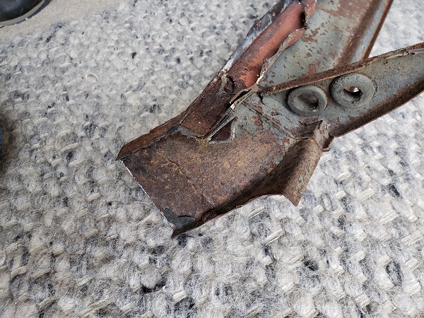
After a little soul searching, decided to refab the whole thing. Making a pattern: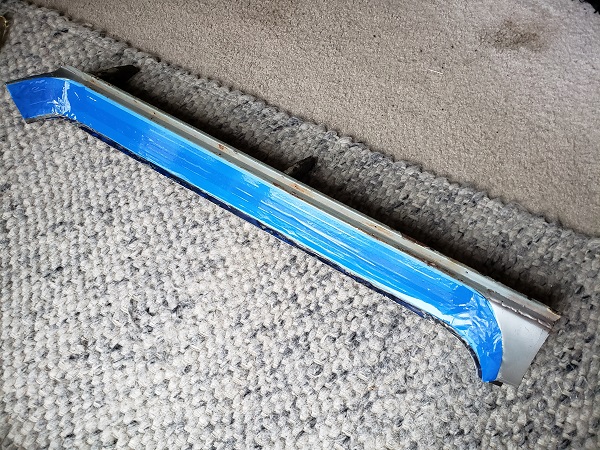
Transferred over to new metal: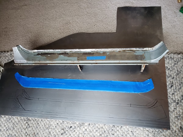
Bending to shape: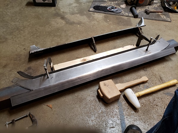
This is about 80% there - at that point I decided it may be best to get the long buttoned up and put the door back on and do the final fit of this guy with the door in place. I'll set this piece aside as it is and come back to it later.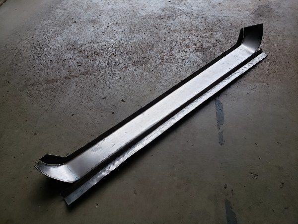
Posted by: 914forme Dec 14 2020, 12:36 PM
Matthew your work always amazes me.
Posted by: bigkensteele Dec 14 2020, 06:08 PM
How has the welder been working out?
Posted by: mbseto Dec 14 2020, 11:52 PM
How has the welder been working out?
Man, it is so much easier. My welds look better - still not professional level, but having a smooth feed and not having to worry about it hesitating makes the whole experience more stress free. I really appreciate the loan, thank you again. I'm waiting on a part before closing up the long. All the prep work has been done so as soon as it arrives I will have pics of the latest welds.
Posted by: bigkensteele Dec 15 2020, 04:42 PM
How has the welder been working out?
Man, it is so much easier. My welds look better - still not professional level, but having a smooth feed and not having to worry about it hesitating makes the whole experience more stress free. I really appreciate the loan, thank you again. I'm waiting on a part before closing up the long. All the prep work has been done so as soon as it arrives I will have pics of the latest welds.
Glad it's working out! I need to get up there and check out your project.
Posted by: mbseto Jan 8 2021, 11:34 PM
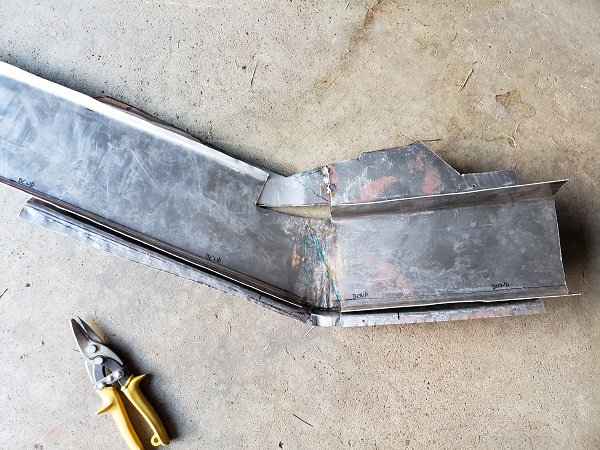
OK, things have taken a left turn, just going to throw some text in here to set the stage. Since the last set of pics, I tacked on the outer part of the long - it was put together as a single piece that goes from the front wheel well to the rear arch, made up of the piece you can buy from RD, a piece I made to extend that piece up the arch, and an inner layer that joins the two. The jack point is also on there.
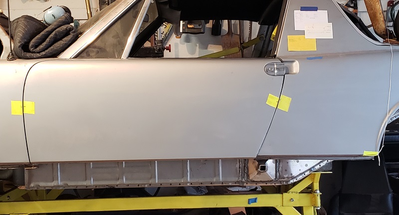
So I tacked that in place and bolted the door back on to check alignment and to use a a reference to final form the new sill. But after putting the door on, I got a bad sinking feeling. The alignment is way off.
I've had door braces in place and I've been measuring every step of the way and was pretty confident it was fine before bolting the door on, but clearly it is not. After thinking it over a while, I think I know what happened, but I can talk about that later. I need a plan.
I'm asking for advice.
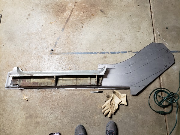
So here's what it look like now...
Posted by: mbseto Jan 8 2021, 11:47 PM
Since this pic was taken, I removed the outer layer of the long. It was only tacked in place. The floor pans are functionally gone - all edges are rusted out or cut except for literally a couple linear inches.
The inner part of the long is welded solid to the good metal in the rear, but is only tacked in the front at the wheel well. The front and rear pieces of it are sleeved solid. The engine mount is tacked in place and would not be hard to remove.
So what I'm thinking right now is-- the whole rear quarter needs to be lowered and rotated a couple degrees CCW. These two movements can be accomplished by
1) repositioning the engine mount to lower the rear quarter and
2) cutting the top and side of the inner long, pulling the gap closed and welding, which will rotate the rear quarter a bit
OK guys, what do you think?
Posted by: tygaboy Jan 10 2021, 12:38 PM
Really sorry to see/hear this. And making any recommendations via pics is a bit dicey. That said: Based on that pic and your description, I'd agree that it sure looks like the back of the car needs to move and rotate.
What about the other side? Does it measure out correctly and do you have good door gaps there? If so, at least you have some points of reference.
When I did my chassis work, I swapped back and forth between two different driver's doors - and yes, they fit differently from one another.
I also found that by barely opening the door, I could lift up/push down on it and tweak the hinge mount area to get the rear edge to better align at the rear.
So maybe try another door? Worst case, it verifies the situation.
And have you fit the roof? That may help confirm where the rear of the car is.
So about all I can offer is before you do any more cutting and welding, try swapping doors and fitting any other parts that will highlight what's where.
Also important: take a deep breath, don't panic. You'll get through this. Remember, it's only metal.
Posted by: 930cabman Jan 11 2021, 06:26 AM
Since this pic was taken, I removed the outer layer of the long. It was only tacked in place. The floor pans are functionally gone - all edges are rusted out or cut except for literally a couple linear inches.
The inner part of the long is welded solid to the good metal in the rear, but is only tacked in the front at the wheel well. The front and rear pieces of it are sleeved solid. The engine mount is tacked in place and would not be hard to remove.
So what I'm thinking right now is-- the whole rear quarter needs to be lowered and rotated a couple degrees CCW. These two movements can be accomplished by
1) repositioning the engine mount to lower the rear quarter and
2) cutting the top and side of the inner long, pulling the gap closed and welding, which will rotate the rear quarter a bit
OK guys, what do you think?
Were the doors ever properly fitting since you owned the car? If so, that is a good baseline to work to getting things aligned properly. Us backyard guys do not have the luxury of a chassis jig/bench so we need to make due. The Egyptians did it. I would be careful moving engine mounts, ....
My guess would be straighten things out in the mid section, longs, floor, ...
Generally the front section is rigid to itself and the rear section rigid to itself, connecting the dots is our work.
The floors on our project were mostly intact, I added a couple spreaders at the front strut mounts to the windscreen frame to the targa bar to the rear strut mounts to keep things together using a spirit level at several locations to keep an eye on things. So far so good.
Do you have 25 1/8" from the windscreen frame to the targa bar?
Posted by: bbrock Jan 11 2021, 08:50 AM
I've been wracking my brain over this much of the weekend and can only agree with what has already been said. Considering the careful and skillful quality of your work, I would be slow to second guess yourself and start moving mounts until you are absolutely sure you have figured out where the sag is coming from first.
As has been said, you can easily take that much sag out of a door simply by banging out bulge/stretch at the top hinge by banging the hinge landing on the post back in place. Unfortunately, it looks like the front gaps of your door is good so would question if that is the problem. Another thing to think about that the windshield frame is easily bent so maybe some careful checking there to make sure you can trust the measurement across the top.
It looks like you have to remove your door brace to install the door. It might be worth rigging an adjustable brace you can use with the door on. I found it really helpful to be able to adjust the brace to understand how the chassis reacts as a whole as measurements change. If it were me, I'd be thinking hard about the inner long alignment as you already are. It's just too hard to say much more from pics. Hopefully some of the guys with Cellete experience can weigh in as they may have insight us garage cobblers don't.
Posted by: 930cabman Jan 11 2021, 10:24 AM
I've been wracking my brain over this much of the weekend and can only agree with what has already been said. Considering the careful and skillful quality of your work, I would be slow to second guess yourself and start moving mounts until you are absolutely sure you have figured out where the sag is coming from first.
As has been said, you can easily take that much sag out of a door simply by banging out bulge/stretch at the top hinge by banging the hinge landing on the post back in place. Unfortunately, it looks like the front gaps of your door is good so would question if that is the problem. Another thing to think about that the windshield frame is easily bent so maybe some careful checking there to make sure you can trust the measurement across the top.
It looks like you have to remove your door brace to install the door. It might be worth rigging an adjustable brace you can use with the door on. I found it really helpful to be able to adjust the brace to understand how the chassis reacts as a whole as measurements change. If it were me, I'd be thinking hard about the inner long alignment as you already are. It's just too hard to say much more from pics. Hopefully some of the guys with Cellete experience can weigh in as they may have insight us garage cobblers don't.
+1 Garage or maybe garbage cobblers could be appropriate
Posted by: mbseto Jan 12 2021, 03:52 PM
First, guys, thanks for the responses, I appreciate the advice and encouragement.
@http://www.914world.com/bbs2/index.php?showuser=19241
What about the other side? Does it measure out correctly and do you have good door gaps there? If so, at least you have some points of reference.
I checked back when I wrapped up that side, but that's been a while. I think I am going to put the door on over there, too. If it's in a similar state, I'd like to take care of it all at once.
And have you fit the roof? That may help confirm where the rear of the car is.
The roof has been in place from the start, I never take it off. My thought was that it would act as an additional brace. I hope that was the right decision.
@http://www.914world.com/bbs2/index.php?showuser=24877
Were the doors ever properly fitting since you owned the car?
Yes, they fit well, but due to the rusted longs, the gaps closed up when jacking the car.
I would be careful moving engine mounts, ....
They were completely removed to replaced the longs. They were repositioned using the dolly as a jig - the mounts sit on plates in the corners of the dolly and those plates were drilled to match when I first mounted the car. I think I may need to un-tack it, let the long down a little bit, then re-tack it.
Generally the front section is rigid to itself and the rear section rigid to itself, connecting the dots is our work.
I suspect the adjustable door braces put a little twist in the rear section.
Do you have 25 1/8" from the windscreen frame to the targa bar?
I'll check that...
@http://www.914world.com/bbs2/index.php?showuser=20845
I've been wracking my brain over this much of the weekend ...
You and me both!! :-)
Another thing to think about that the windshield frame is easily bent so maybe some careful checking there to make sure you can trust the measurement across the top.
The little triangular part of the door window is laying perfectly in its seal.
It might be worth rigging an adjustable brace you can use with the door on.
This is wise advice, I am wishing I had started out that way.
Posted by: Superhawk996 Jan 12 2021, 04:23 PM
And have you fit the roof? That may help confirm where the rear of the car is.
The roof has been in place from the start, I never take it off. My thought was that it would act as an additional brace. I hope that was the right decision.
Sorry to see this latest development.
As other have said don't panic. Dont do anyting rash in a hurry. I think the main point you missed from Chris was to use the roof to gauge whether the rear has twisted. The roof should have approximately the same length of overhang on each side of the sail panel. The roof provides no real bracing. The attachments are simply to weak to do anything meaningful. It is useful as a gauge though. If it is twisted, you should have quite a bit of asymetry in the targa overhand to the sail and/or differnt for/aft fit along the width of the targa.
You can have quite a bit of twist and it wouldn't affect the 25 1/8" dimension from targa bar to windshield frame.
I'd second the approach of creating door braces that can be used with the doors installed. That is what I've done and haven't regretted the time spent to fabricate them for a moment. As Brent said, you'd be surprised how little adjustment on the braces is needed to affect gaps in a big way.
For what it's worth, I've found the transition from the horizontal long to the angled engine compartment area to be very sensitive. My chassis was completly fine until I decided to weld in a joint doubler. After that my outer suspension console moved in Z-height by 4-6mm. Nothing else moved in X or Y dimension. I still have not resolved this on my car since I can offset it with trailing arm shims. But I'll tell you it bothers me and I may still fix it but will only do so once the inner suspension console and the engine mount are installed.
If you think about that transition, being sort of a hockey stick shape, a little twist in the long and/or that transition area will affect the things aft of it.
You might want to take a close look at whether your welds in that transition area have twisted the rear. I'm pretty sure if you can hone in on where the twist originated, you can cut some welds and resolve it without resorting to using the engine mount to pull it.
You know this from metal shaping - especially shrinking. You can chase things with the part deforming in ways you don't want. Then you find just the right spot to shrink and BOOM it all pops into place, is what you wanted from the get-go and is dimensionally stable after that.
Posted by: 930cabman Jan 12 2021, 05:28 PM
And have you fit the roof? That may help confirm where the rear of the car is.
The roof has been in place from the start, I never take it off. My thought was that it would act as an additional brace. I hope that was the right decision.
Sorry to see this latest development.
As other have said don't panic. Dont do anyting rash in a hurry. I think the main point you missed from Chris was to use the roof to gauge whether the rear has twisted. The roof should have approximately the same length of overhang on each side of the sail panel. The roof provides no real bracing. The attachments are simply to weak to do anything meaningful. It is useful as a gauge though. If it is twisted, you should have quite a bit of asymetry in the targa overhand to the sail and/or differnt for/aft fit along the width of the targa.
You can have quite a bit of twist and it wouldn't affect the 25 1/8" dimension from targa bar to windshield frame. THINK PARALLELOGRAM , FITTING THE ROOF PANEL SHOULD PROVE/DISPROVE THIS
I'd second the approach of creating door braces that can be used with the doors installed. That is what I've done and haven't regretted the time spent to fabricate them for a moment. As Brent said, you'd be surprised how little adjustment on the braces is needed to affect gaps in a big way. YES AGREED
For what it's worth, I've found the transition from the horizontal long to the angled engine compartment area to be very sensitive. My chassis was completly fine until I decided to weld in a joint doubler. After that my outer suspension console moved in Z-height by 4-6mm. Nothing else moved in X or Y dimension. I still have not resolved this on my car since I can offset it with trailing arm shims. But I'll tell you it bothers me and I may still fix it but will only do so once the inner suspension console and the engine mount are installed. INTRODUCING EXTREME HEAT (WELDING) DOES WEIRD THINGS TO EVEN HEAVY GAUGE METAL, MORE SO ON THIN GAUGE
If you think about that transition, being sort of a hockey stick shape, a little twist in the long and/or that transition area will affect the things aft of it.
You might want to take a close look at whether your welds in that transition area have twisted the rear. I'm pretty sure if you can hone in on where the twist originated, you can cut some welds and resolve it without resorting to using the engine mount to pull it.
You know this from metal shaping - especially shrinking. You can chase things with the part deforming in ways you don't want. Then you find just the right spot to shrink and BOOM it all pops into place, is what you wanted from the get-go and is dimensionally stable after that.
BEST OF LUCK, THINK IT THROUGH BEFORE TAKING ACTION
Posted by: mbseto Jan 16 2021, 03:25 PM
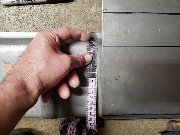
Since the last set of posts, I put the passenger side door back on, just to make sure that side still looks OK. Thankfully, it does. Also per the suggestions you guys had, I inspected the roof overhang and measured to window-frame-to-targa-bar. The roof overhang was even across the back. I took the targa off and the frame to bar was dead on 25-1/8" on the passenger side, but about 25-1/2" on the driver's side. Which of course matches the twisted door gaps on that side.
I checked the cockpit for square by running strings diagonally across. The string just touch in the center, so wherever this problem starts, it is behind the firewall.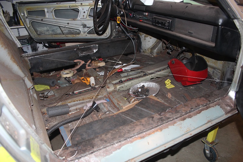
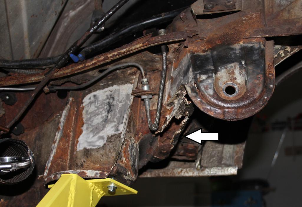
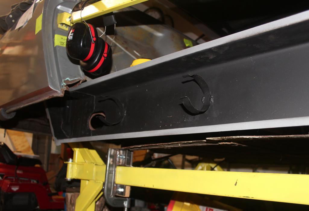
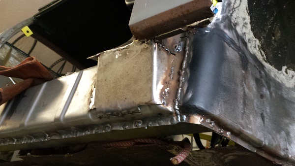
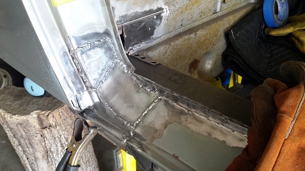
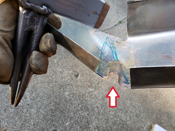
So I spent a couple sessions just sitting on the couch with a glass of bourbon and pondering the overall structure. I think the problem starts with the joint I made between the horizontal section of the long and the angled section. Right where the arrow is below, you can see a strip of metal about an inch wide that joins the two.
And here is what killed me... My dolly is on the short side - it goes from the front axle to the engine mounts. So the whole back section is cantilevered. I was counting on the door braces to hold everything in place, but they acted like the wishbones on a double wishbone suspension. Like the parallelogram that @http://www.914world.com/bbs2/index.php?showuser=22428 mentioned, all the linear measurements are held, but the angles can change. So when I measured the door opening at the bottom, it was correct, but it was no longer dead horizontal.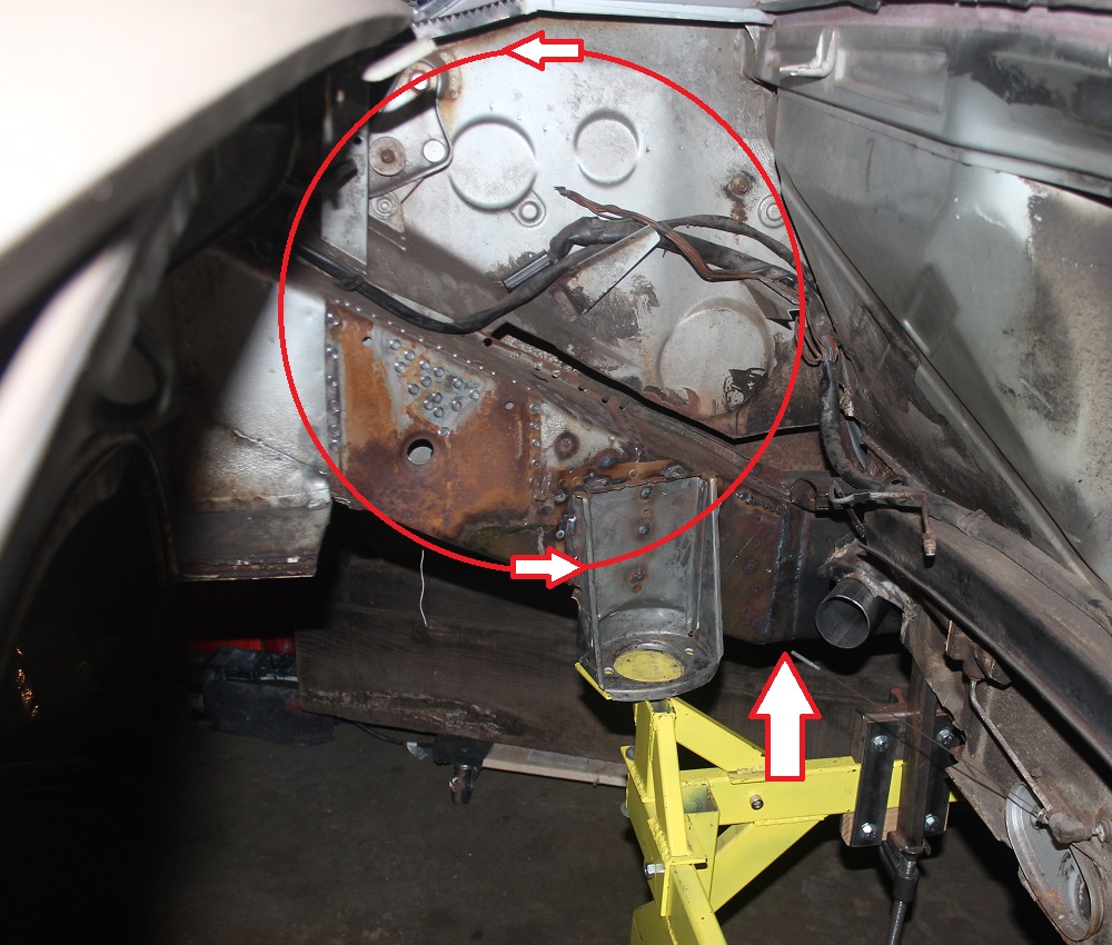
So I put that circle right about where I think the whole thing rotated. To fix this, I need to cut the long at the arrow and open that gap up about a centimeter. I'll need the brace to pull back at the shoulder belt point to straighten it all up, then re-weld. As suggested, I'll whip up a brace that can go on with the door in place.
The engine mount will have to come off... I won't use it to try to pull anything into place, but it will have to be repositioned because the whole rear is going to move and it needs to stay where it is relative to the rest of the car.
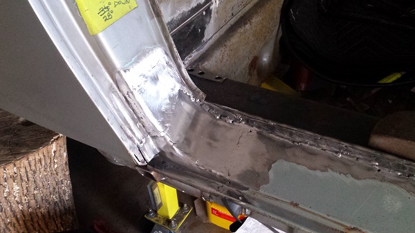
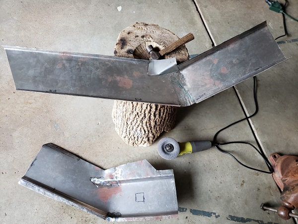
Right now the only thing that bothers me about fixing this is the inner layer. Here's the reverse angle below. That sleeve was made so that no welds on the outer would coincide with welds on the inner. They aren't even in the same direction, all the outer welds are vertical and all the inner welds are horizontal. It's going to be tough to cut through the long and then put it back together without the outer and inner both having a weld in the same place, right on top of each other. That inner layer is rosette welded solid in there. It's going to be tough to remove any part of it to get the welds where I want them...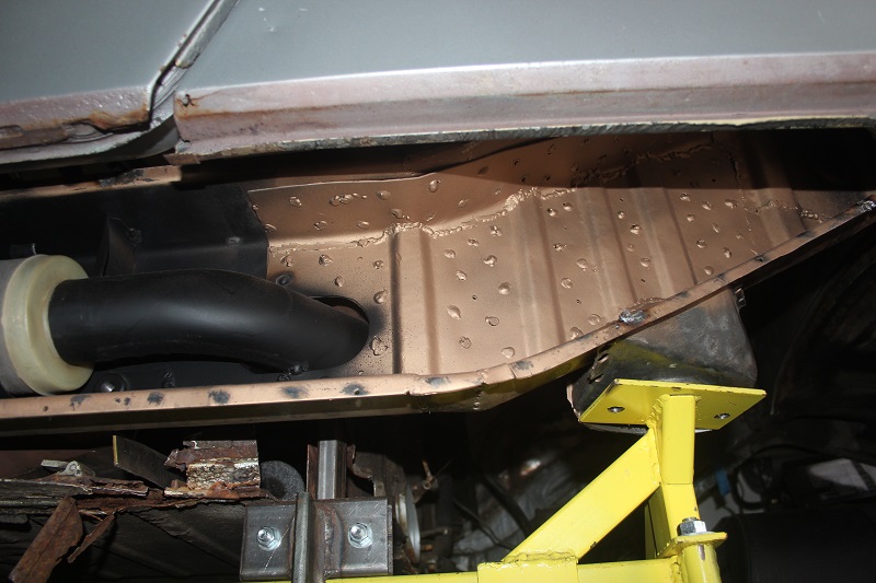
Posted by: Superhawk996 Jan 16 2021, 03:41 PM
Nice work tracking it down. Sounds like you're developing a plausible plan.
This is where copying Jeff Hail's cart may have saved me and made my life easier. My chassis is held at the rear trans mounts and the front axle. Prevents that type of cantilever and tendency for things to sag at the rear when welding.
It's not like I thought that through in advance but now that you mention your issue, I think I got lucky just copying Jeff's cart! Sometimes I'd rather be lucky than good!
That place where your single red arrow is . . . it's exactly the same spot where I welded my doubler that caused by outer suspension console to lift in Z. Sensitive area. Take your time, go slow, and keep it cool when you weld it back up.
Posted by: 930cabman Jan 16 2021, 04:22 PM
Introducing heat to our thin gauge frames can (and often does) wreak havoc. I am a carpenter by trade but have done quite a bit of steel fabrication along the way. I can recall a project many years ago with 4" schedule 40 pipe. I chased the bending for quite some time, but finally got it right. I have had some challenges with our 914, hopefully on the right road. I have had to cut some work apart, reposition the pieces and reweld.
A double/triple check would be to place a spirit level on the front strut mountings and compare it with placing the level on the rear strut mountings
Think it out thoroughly before you cut.
Best of luck
Posted by: mbseto Feb 6 2021, 10:01 PM
So there's been a lot of thinking going on, and a lot of poking and prodding to try to figure out how this thing move when I put pressure in different places. Went ahead and made a brace that she could wear with the door installed, that part was a no-brainer. I've seen some other guys make these, but didn't really have the search terms to find the parts I need. Looked familiar, just didn't know what it is called. Spent a Sunday out at my buddies farm to help with some chainsaw work in exchange for some firewood, and as we were hitching up the trailer, I realized where I've seen this part a thousand times. "What's that?" I asked my buddy, pointing to the part as we are dropping the bush hog to hitch up the trailer. "That? That's the top link." Off to Tractor Supply to buy a top link and cut it up.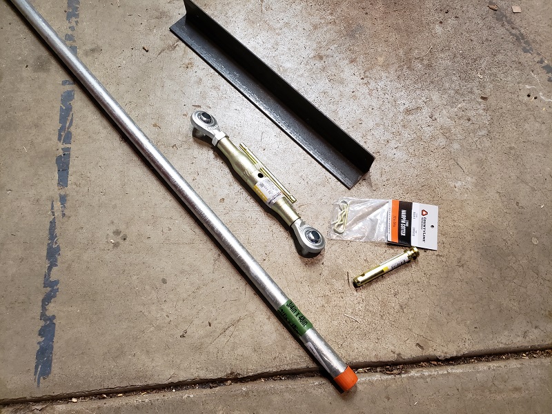
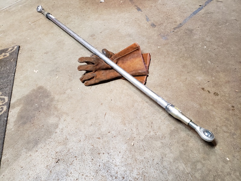
The top link was about $27 as I remember and with the other bits it was probably under forty-five total. I was trying to control costs pretty strictly with the first set of braces, but after playing with this one a little bit and the ease with which I can adjust it, I think this is the way to go.
Just a twist, and the frame moves: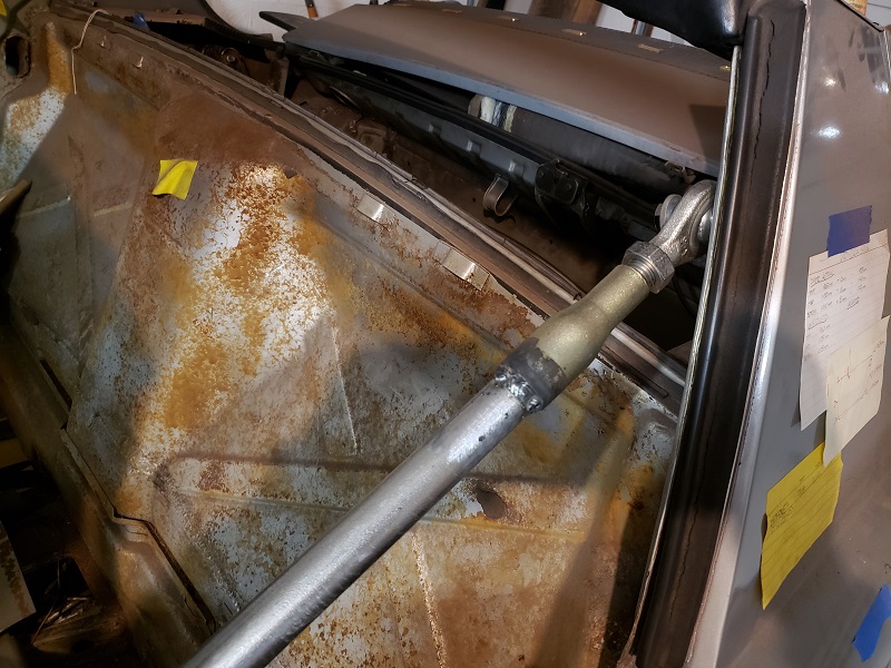
So here's the before pic of the gaps. It looks worse in real life, the pic actually does not show how bad it is.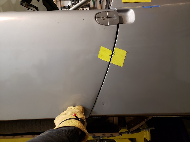
Here's an actual measurement at the top.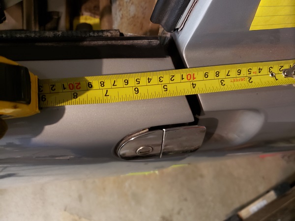
Posted by: mbseto Feb 6 2021, 10:17 PM
So I installed the new brace, cut through the long just aft of the horizontal section, and also removed the engine mount. Now I'm trying to figure out what needs to happen to line everything up again. If I tighten that brace, the whole quarter moves forward and back. So the gap at the top closes to the right size, but the gap at the bottom, which is already completely closed, closes even more. I was expecting thinking wishfully that it would pull the top in and rotate the bottom back and everything would magically come together. No such luck.
Another thing I tried was throwing my stump under the rear of the car and putting a scissor jack on it, and gently lifting it at the trans mount. With the whole rear cantilevered off the engine mounts, I figured letting that weight off might let the whole rear quarter rotate, closing the top gap and opening the bottom. Nope, it just lifted the whole car up. Even with the long and firewall severed, the frame is surprisingly rigid.
Seemed like I needed to push the long apart where I had made the cut, but I have no sort of tool to do that. So I made this little pushme-pullya: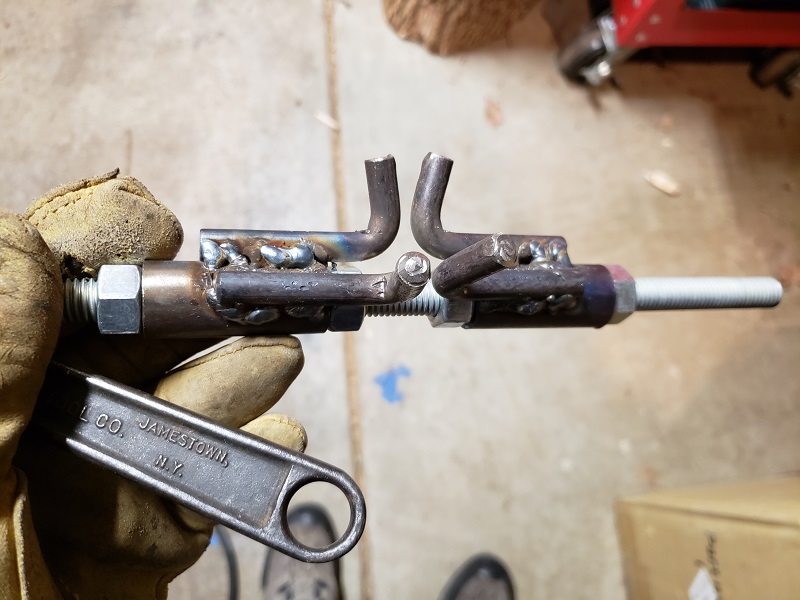
Stuck him in the gap and started twisting. That started to open up that lower gap. Now we're getting somewhere... Something to note in this photo - my dolly is designed to hold the frame by the engine mount. With the mount removed, I need something in that corner to support the frame. The solution is that thing you see clamped to the dolly rail. It is a repurposed C-clamp that supported a strut that slides up between the two walls of the firewall. I can adjust it up and down to get everything level before reattaching the engine mount.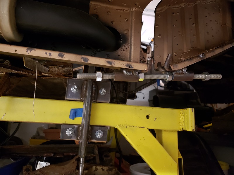
Posted by: mbseto Feb 6 2021, 10:46 PM
With this additional adjustment that I can make, I started with the door brace and tightened it until I had a window-frame-to-targa-bar measurement of 25-1/8". The door gap at the top looked about right too.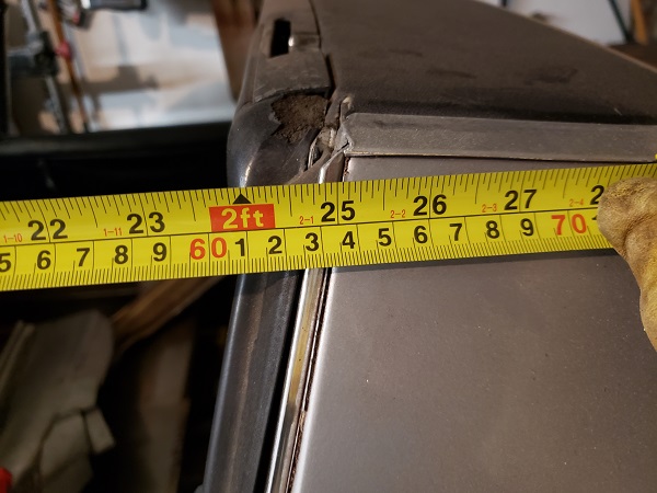
Next, I cranked on the pushme-pullya and it slowly opened up the lower gap until it also looked much better. I was able to improve the horizontal alignment by clamping the long to the flange on the firewall (where it will eventually be welded). I feel like it is about 95% better: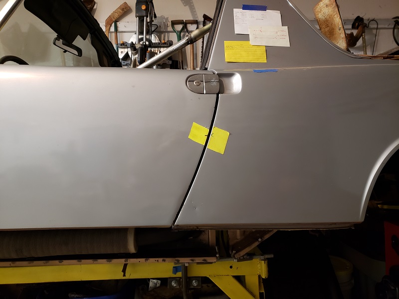
So I feel like there is a way out of the woods now. Once again, thanks guys for the advice and encouragement. I surely welcome any comments on what you see above. I'm anxious to get some tacks in place and see this straightened out for good.
Posted by: Cairo94507 Feb 7 2021, 08:56 AM
That is way, way better than what it was. Nice job identifying the issue so you can remedy it for a very nice fit.
Posted by: tygaboy Feb 7 2021, 09:35 AM
You just earned the "Perseverance Award" in my book. Staring down that sort of do-over would likely have done me in. BIG kudos to you!
And great job engineering those correction tools. Really impressive.
The only thing I'd add at this point it is that when I did my chassis work, I'd do as little welding as was needed to hold things in place, then I'd back off all the support rods, bracing, pushme-pullya stuff and see if things still measured out.
I found that it worked best for me to "over set" that 25 1/8" measurement to a bit wider during welding since I assumed shrinkage would pull things at least some. YMMV, but given what we're seeing, I'd say "You got this!"
Thanks for sharing this. It's going to help others. Again, really, really great recovery.
Posted by: Amenson Feb 7 2021, 03:15 PM
It was clear from your earlier posts that you were adventurous and had the skills to pull it off. This is downright fearless.
Keep it up, this is awesome.
Posted by: 930cabman Feb 7 2021, 03:57 PM
It was clear from your earlier posts that you were adventurous and had the skills to pull it off. This is downright fearless.
Keep it up, this is awesome.
Perseverance is almost always a good thing. I am sure a glass or two of bourbon helped the process along. First fix the issue in your brain, then carry it out in practice. "Sir Issac Newton" basic philosophy when asked how he came upon gravity, calculus, ...
Glad to see you have made progress after a small setback
Posted by: bkrantz Feb 7 2021, 08:24 PM
Outstanding work! You deserve an award for staying optimistic and clever in the face of severe adversity. Lesser people would have "fixed" that mis-alignment with a big hammer and some bondo (lots and lots of bondo).
Posted by: timothy_nd28 Feb 7 2021, 11:11 PM
Thanks for sharing and being very detailed with your repairs. I made a huge huge huge dumb mistake when working on my 914. I had my tub on a rotisserie, and the tub was upside down on this rotisserie. I didn't have the doors or anything braced when I welded in new floor panels. That gap on your driver door looks extremely similar to what I have. I will definitely be referring back to this thread when it comes time to make my repairs. Thank you and keep them pictures coming!
Posted by: mbseto Mar 22 2021, 10:23 PM
Nothing informs the quality of your welds quite like a hammer and cold chisel.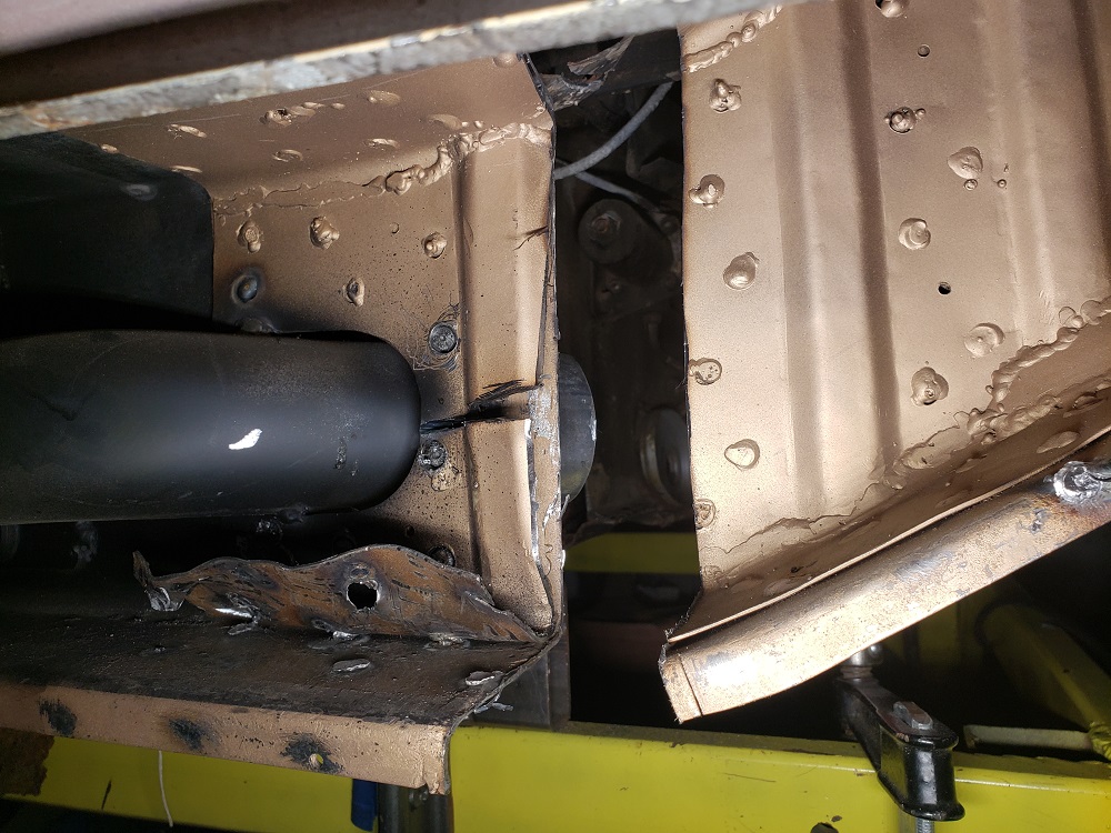
Posted by: Arno914 Mar 23 2021, 01:33 AM
Before final assembly, is there any possibility of getting the car on a "Celette" to make sure? Maybe your door gaps are fine now, but what if the alignment is out of spec.? I think it would be a wise investment considered all the tremendous work you have done so far. The section behind the firewall is very sensitive for that matter.
Powered by Invision Power Board (http://www.invisionboard.com)
© Invision Power Services (http://www.invisionpower.com)