Printable Version of Topic
Click here to view this topic in its original format
914World.com _ 914World Garage _ 911 oil temp/pressure guage
Posted by: trekkor Mar 2 2005, 11:47 AM
I have the guage in the car and the temp side is wired.
It's the pressure and idjit light that I need help with.
New wires are run from the senders to the guage.
What wire goes where?
I have four wires. One off the idiot sender and three off the pressure sender.
Help me help myself. 
Attached image(s)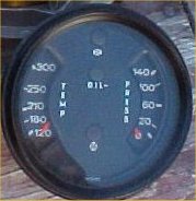
Posted by: Aaron Cox Mar 2 2005, 12:15 PM
ok...all the gauges are labeled. they need 3 things. A switched + (i jumpered the existing one for the fuel gauge) and a Ground (once again jump/split the grounds taht are there) and the wire from the sender.
your green wire from the console tempgauge can be extended.....that goes to the remaining terminal on the temp gauge. now the other wire you magically ran from your oil press sender goes to the remaining terminal on that gauge.
They are labeled you know
+ / sender symbol and G
Posted by: lapuwali Mar 2 2005, 12:22 PM
Three off the pressure sender?
There should be no more than two wires off the pressure sender, one for the idiot light, one for the pressure signal. The gauge also needs +12 and ground. The ground wire will be brown, so that's one. The two pressure sender wires should have the same color as they do at the sender (unless there's been mass hackage), that's three. The fourth wire will be the +12.
Posted by: Aaron Cox Mar 2 2005, 12:29 PM
| QUOTE (lapuwali @ Mar 2 2005, 11:22 AM) |
| Three off the pressure sender? There should be no more than two wires off the pressure sender, one for the idiot light, one for the pressure signal. The gauge also needs +12 and ground. The ground wire will be brown, so that's one. The two pressure sender wires should have the same color as they do at the sender (unless there's been mass hackage), that's three. The fourth wire will be the +12. |
ayup... the sender (presure) has only 2 terminals.... one for the idjit light, and one that goes to the pressure gauge (i think it is labeled G)
Posted by: trekkor Mar 2 2005, 12:31 PM
The temp side is already dialed
It's the three wires on the pressure sender that trouble me.
And the idiot... 
KT
Attached image(s)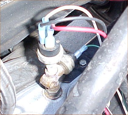
Posted by: trekkor Mar 2 2005, 12:33 PM
oh, and the wire colors shown mean nothing. Just four different colors for easy ID in the dash.
KT
Posted by: lapuwali Mar 2 2005, 12:44 PM
I've never seen a pressure sender that looked like that. I'd speculate that one of the wires is ground for the sender itself (as it it doesn't ground through the connection to the block, as usual). Where did you get that sender? Do you know if it will match the 911 gauge?
If you can't find any information on that sender, you would probably do yourself a favor by just buying the correct VDO sender for that gauge, which is a traditional 'can' type sender with two terminals on it. It's only $20-30.
Posted by: trekkor Mar 2 2005, 12:45 PM
Soooo, in my pic, let's say the white is ground and the red is 12+ jumpered from the dash and the black is sender signal?
May not be that way in the pic but that's the idea?
Green is obviously attatched to the idiot sender. Does it wire to the indicator light on the guage with the other side 12+?
Posted by: ! Mar 2 2005, 12:47 PM
The gauge I had did not work with the sender on the engine....I had to get the two wire VDO one....make sure you get a sender that matches the scale on the gauge. GPR was where I got mine....
Posted by: ArtechnikA Mar 2 2005, 12:58 PM
need more data...
what year is your combo gauge? ideally, what's the part number? i have those same instruments but a different combo gauge (no oil idiot light in 1971...)
what is the part number of the sender? (hint: if it's not the sender from the Porsche that donated the gauge, it's probably not going to work right...)
(not that it matters much, because that whole thing is likely to crack from the vibration and fall off, at which time the oil pressure is zero and the temp is not important...)
if i had to guess, it's be that the sender is some kind of combination gauge driver (variable resistance) and pressure switch (for the light).
Posted by: lapuwali Mar 2 2005, 01:07 PM
| QUOTE (trekkor @ Mar 2 2005, 10:45 AM) |
| Soooo, in my pic, let's say the white is ground and the red is 12+ jumpered from the dash and the black is sender signal? May not be that way in the pic but that's the idea? Green is obviously attatched to the idiot sender. Does it wire to the indicator light on the guage with the other side 12+? |
The idea is that the idiot light has +12 on one side of the bulb, and the other side is grounded through the sender. The sender here is just a switch that OPENS above some set pressure, and closes below that. The gauge is similar, except the ground is through a variable resistor that changes resistance (to ground) based on the pressure. The gauge needs a separate "real" ground to act as a reference so it knows how far the pressure sender "ground" is from the "real" ground. The difference is displayed on the gauge.
In the two-post VDO sender, one terminal is for the light, one for the gauge, and the ground is through the threads in the sender into the engine block.
This oddball sender COULD have a separate ground wire, rather than grounding through the threads. If that's the cause, then one post will be light, one will be gauge, and the third you just ground somewhere. It also COULD ground through the threads and the third wire is +12, which is used by some active device inside the sender. As I said, I've not seen one of those senders, so all I can do is guess.
You could try measuring this sender to see what's what. See what the resistance is between pairs of wires (three ways to do this). If one wire is a ground wire, then you'll probably get 0 ohms between two wires and something above 0 between two others and infinite between the last pair. The pair with 0 ohms are the ground and the light switch. The pair with something above 0 are the ground wire and the pressure sender, and the last are between the light switch and the pressure sender. If you think you've got a handle on that, try starting the engine and see how the resistances change. The light/ground wire pair should now show infinite (switch open), the pressure/ground wire pair should show something other than what you measured with the engine off, but it shouldn't be 0 or infinite. The last pair should still be infinite.
Posted by: Dave_Darling Mar 2 2005, 01:11 PM
This is from a six-cylinder engine, right?
As I recall, the 911 engines had separate senders for the oil pressure warning light and oil pressure gauge. It is possible that I'm only remembering info that applies to some years and yours is a different year...
OK, the 71, 73, and 82 wiring diagrams on Pelican all say separate senders for light and gauge, and one wire plugged into each sender. So I'm out of ideas.
Try asking on some 911 forums.
--DD
Posted by: Aaron Cox Mar 2 2005, 01:13 PM
the hot tip is to get the vdo dual post sender. one does the idiot light...one does the gauge. get grounds and switched hots in the area behind the gauge....
THREAD HIJACK-
how do the dual post /6 senders differ from the dual post /4 senders??? IE 911 gauge on a type 4
Posted by: ArtechnikA Mar 2 2005, 01:18 PM
| QUOTE (Dave_Darling @ Mar 2 2005, 02:11 PM) |
| OK, the 71, 73, and 82 wiring diagrams on Pelican all say separate senders for light and gauge, and one wire plugged into each sender. |
as standard, '71 T has a light and no gauge.
'71 E and S have gauge and no light.
temp and pressure gauge senders have exactly one wire attached.
if it were me, i'd dump that whole cobbled assemblage and just get new matched senders, but that's just me...
Posted by: trekkor Mar 2 2005, 11:45 PM
![]()
Anymore Ideas?
KT
Posted by: ArtechnikA Mar 3 2005, 05:48 AM
| QUOTE (trekkor @ Mar 3 2005, 12:45 AM) |
| Anymore Ideas? |
since you don't want to tell us where the gauge or the senders came from, i'm staying with the original suggestions:
1) shitcan the senders you've got and put in senders known to match the gauges.
2) shitcan the gages you've got and put in gages known to match the senders.
3) spend several/many hours with an ohmmeter measuring between each pair of contacts while varying pressure over the operating range.
the problem with #3 is that at the end of many tedious hours of sender characterisation, you may know conclusively that the senders are not compatible with your gages and you'll wind up doing #1 or #2 anyway. or, once you've got the characterisation curves, you can send the senders, the gages, and a grocery bag of Benjie's off to PA Speedo and get them calibrated to match.
Posted by: lapuwali Mar 3 2005, 10:37 AM
| QUOTE (trekkor @ Mar 2 2005, 09:45 PM) |
| Anymore Ideas? KT |
Sure, spin aroung three times, spit on a rock, then bonk yourself in the head with a baseball bat.
Otherwise, follow Rick's advice. Like I said, a new sender is all of $30.
Posted by: trekkor Mar 3 2005, 10:51 AM

It was late and was confused...
Thanks for the advice.
Sender hunt.
KT
Posted by: ! Mar 3 2005, 10:57 AM
Call Dave at GPR....800-321-5432 ext 502
Posted by: type47fan Mar 3 2005, 08:19 PM
| QUOTE (trekkor @ Mar 2 2005, 10:31 AM) |
| The temp side is already dialed It's the three wires on the pressure sender that trouble me. And the idiot... KT |
You can always replace your rear brake proportioning valve with the brake line tee that's supporting all of the senders when you upgrade to larger front calipers!
Powered by Invision Power Board (http://www.invisionboard.com)
© Invision Power Services (http://www.invisionpower.com)