Printable Version of Topic
Click here to view this topic in its original format
914World.com _ 914World Garage _ Just another 2056 build
Posted by: sdoolin Jan 13 2016, 04:29 PM
Yep, I am building a 2056. Have ordered very nearly a complete 2056 engine kit from Type IV Store (LN Engineering). Some questions (I have searched and read MANY threads)...
I have a "spare" 1976 VW Bus short block (no cyl. heads). Assume this will work for a starting point? Issues with oil dipstick? The bus was an automatic so I assume once I remove the "flex plate" that the flywheel from by 914 engine (in car) will bolt up to the crank without issues? Any issues with engine carrier? The bus used a "moustache bar" for mounting to the frame and I am hoping that the cases from the bus/914 are the same for engine mounting?
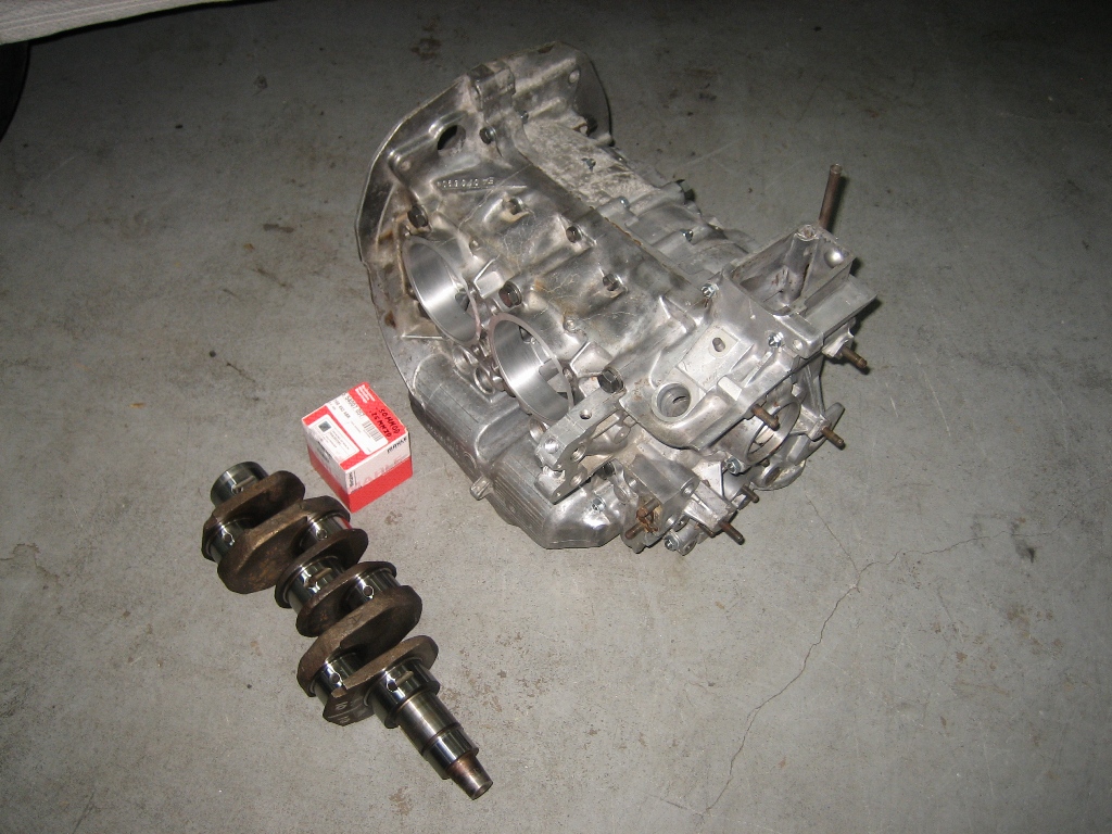
Will re-use existing Crank/rods
New crank/rod bearings
Will re-use existing cylinders (overbored)
KB 96 mm flat topped pistons with Hastings rings
Webcam cam (9130 kit from Type IV Store)
Type IV Store pushrods, pushrod ends, parkerized lifters, rocker shafts
Type IV Store cam bearings
Re-use rockers from bus engine? Not sure about this...
HAM (Len Hoffman) RS+ spec cylinder heads
New Oil pump from Type IV Store
New clutch & pressure plate.
Re-use flywheel from 914 engine (in the car)
Dellorto Dual 40mm carbs, CB Perf manifolds & linkage
SSI heat exchangers & Bursch exhaust
New fuel pump - will run return lines (have CFR SS Lines in car now and will re-use)
Not sure what dizzy to run?
I believe I need to check/verify deck height and valve clearance (I know how, just not positive this is required for a 2056 build).
I have read a few threads about "setting" compression ration, but do not understand it yet? Anyone have a compression ratio for dummies guide?
Anything else I'm missing?
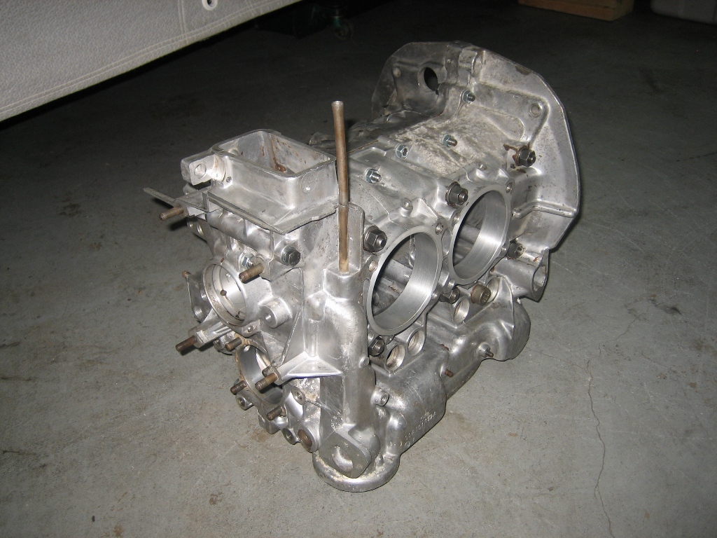
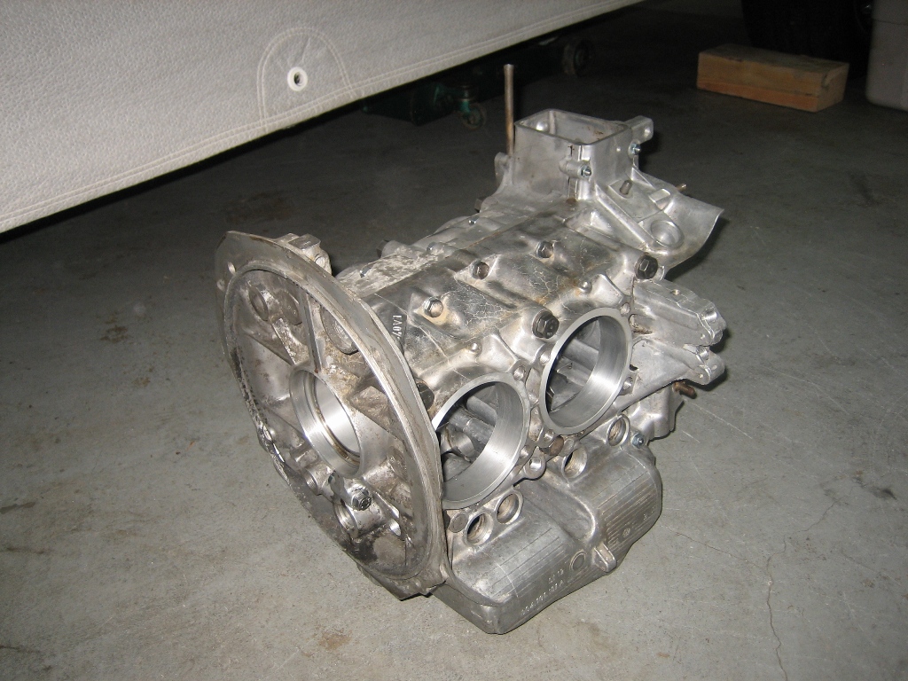
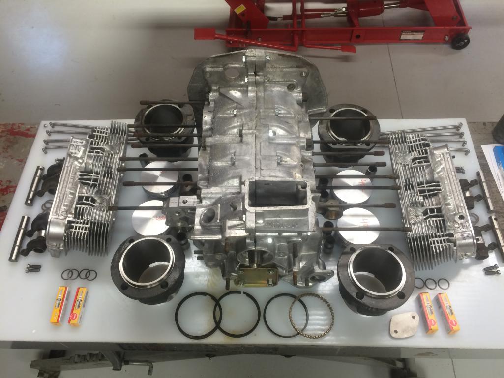
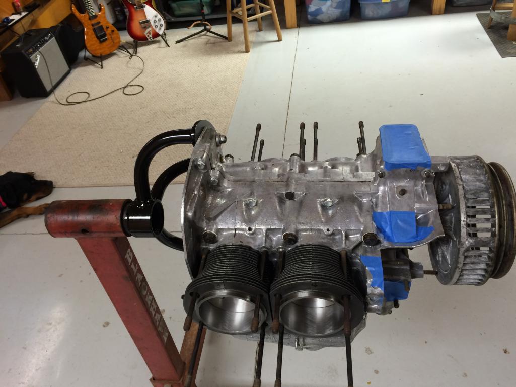
Progress so far...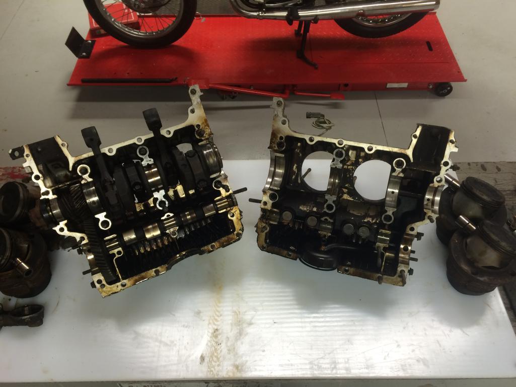
Posted by: Valy Jan 13 2016, 04:52 PM
Block off the bus oil dipstick hookup and install a 914 dipstick.
See my signature for the gaskets you need on the block-off plate.
Posted by: Dave_Darling Jan 13 2016, 06:30 PM

You set the compression ratio by moving the cylinder heads outward (lowers compression) or inward (raises compression). Moving the heads out can be done by adding spacers under the cylinders. Moving them inward is usually done by fly-cutting the heads, though machining the cylinders probably can work too.
The simple version is that the compression ratio is the ratio of volume of the whole chamber plus cylinder at BDC to the volume of the same stuff at TDC. You can calculate that in a few ways, the most common is:
(swept_volume + fixed_volume) / (fixed_volume)
The swept volume is determined by the bore and stroke of one cylinder, with a 2056cc that would be (96/2)*(96/2) * 71 * 3.14159 / 1000 ~= 514cc. (Or 2056cc / 4.)
The fixed volume is measured in several parts that are added together. The combustion chamber volume is measured using your cylinder heads and your spark plugs and your valves and such. The height of the cylinder above the piston is measured, and used to calculate the volume of the space left above the piston. Dished or domed pistons get measured for volume (how depends on the piston) and that volume gets added to (dished) or subtracted from (domed) the fixed volume.
Then you plug the numbers in and see what your compression ratio is. Then see how much you need to add to the fixed volume to lower the number to where you want it, or how much you need to remove from the fixed volume to raise the number.
... Or you take the whole shebang to a good machine shop and tell them you want X for the compression ratio and they do it all for you...

--DD
Posted by: sdoolin Jan 14 2016, 06:05 AM
Valy - thanks for the info. The case I am hoping to use does not have a hole for a dipstick. I suppose I can drill one?
See pic...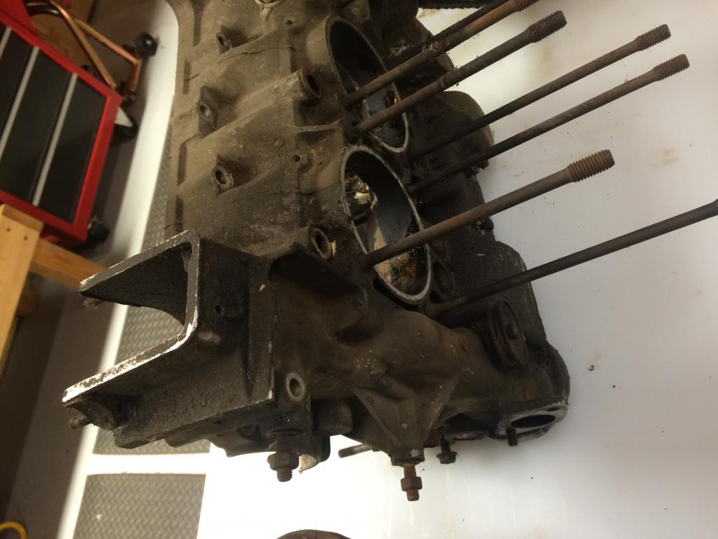
DD - thanks for the "compression ratio for dummies" guide. That is quite helpful.
Posted by: The Cabinetmaker Jan 14 2016, 07:14 AM
Why not source a 914 case?
Posted by: sdoolin Jan 14 2016, 07:47 AM
Why not source a 914 case?
Good question. I had this laying around and hoped to use it (free and all). I may have to buy cases...
Posted by: r_towle Jan 14 2016, 07:33 PM
Check to make sure it's straight, the crank journals are straight and the deck (where the cylinders sit) is one flat plane.
Most machine shops will tell you to line bore the case without bothering to measure it.
You can measure everything I said above on your own with a good set of tools.
Posted by: McMark Jan 15 2016, 08:47 AM
Yup, check condition of the case before you put more work into it. You can drill a new dipstick hole if the case is good.
Posted by: malcolm2 Jan 15 2016, 12:31 PM
Sorry I did not read thru the whole post and all comments.... maybe I won't cover something mentioned. But my 2 cents:
I have read that if you have a choice,
1. start with a 1.7 case. Clearance is required to build over a 1.8 with it, but I believe they are beefier all 'round.
2. You will hear it all the time... Bus engines push heavy buses, you might be starting with a more worn case mile for mile.
3. Study up on the benefits of using 911 rockers with swivel feet, not a big expense, but you should decide.
4. buy the kit and pull the pressed in oil galley plugs with screw in type. once I put a drill bit on the big ones, they FELL out. Imagine what would happen with oil pressure.... 
5. I re-used the PP, FW and resurfaced the clutch in my daily driver. Took them all to a shop that specializes in clutches and they made them like new for about $150.
6. on your CR question, Len will be able to tell you the volume of the combustion area in the head. If he is supplying. IIRC mine was something like 55cc?  He wrote it with a sharpie on the head.
7. find a copy of Jake's video to go with all the books you should have also purchased... 
Posted by: Sedonut Jan 15 2016, 02:39 PM
You should be able to buy a 914 case cheap. Like maybe $50.
The other factor if if you take a little bit of time to find the right case for your car, I will make your car a little more valuable. If it were me, and I did , find a GA case so you have a 2.0 case as you are building a 2.0 engine. You can put "correct 2.0 case" in your sales ad, it all gets sold eventually.
To give you an idea if what I have paid over the past year, a fresh long block 2.0 case, 1.8 heads for $1600, a 2.0 case and crank from a generous 914 world member for $380, and a 2.0 case I picked up with some parts from another 914 world member for $50.
Posted by: sdoolin Jan 15 2016, 06:13 PM
You should be able to buy a 914 case cheap. Like maybe $50.
The other factor if if you take a little bit of time to find the right case for your car, I will make your car a little more valuable. If it were me, and I did , find a GA case so you have a 2.0 case as you are building a 2.0 engine. You can put "correct 2.0 case" in your sales ad, it all gets sold eventually.
To give you an idea if what I have paid over the past year, a fresh long block 2.0 case, 1.8 heads for $1600, a 2.0 case and crank from a generous 914 world member for $380, and a 2.0 case I picked up with some parts from another 914 world member for $50.
My car has a running (numbers matching and original) 2.0l in it, all stock FI and all. So I will keep that engine in house should I ever decide to go full concourse with this car (which will NEVER happen). The 2056 I'm building is just for "fun" and I am hoping to use this set of bus cases.
Thanks for the suggestions, I agree correct and numbers matching engine increases value.
Posted by: sdoolin Jan 15 2016, 06:26 PM
Sorry I did not read thru the whole post and all comments.... maybe I won't cover something mentioned. But my 2 cents:
I have read that if you have a choice,
1. start with a 1.7 case. Clearance is required to build over a 1.8 with it, but I believe they are beefier all 'round.
2. You will hear it all the time... Bus engines push heavy buses, you might be starting with a more worn case mile for mile.
3. Study up on the benefits of using 911 rockers with swivel feet, not a big expense, but you should decide.
4. buy the kit and pull the pressed in oil galley plugs with screw in type. once I put a drill bit on the big ones, they FELL out. Imagine what would happen with oil pressure....
5. I re-used the PP, FW and resurfaced the clutch in my daily driver. Took them all to a shop that specializes in clutches and they made them like new for about $150.
6. on your CR question, Len will be able to tell you the volume of the combustion area in the head. If he is supplying. IIRC mine was something like 55cc?
He wrote it with a sharpie on the head.7. find a copy of Jake's video to go with all the books you should have also purchased...
Thanks for suggestions.
I am starting with a known 2.0l case (from a bus).
Agree on your number 2, cases will get measured before any new parts installed.
Will certainly study the 911 swivel feet rockers, my Cam kit came from Type IV Store does include ball-ends for the pushrods.
Oil galley plugs will be removed/replaced
I have new clutch, PP, and will re-use existing FW (assuming it will bolt to crank - witch I gotta believe it does_
I will speak with Len on CC volume, he and I have already exchanged several messages.
I have Raby's video - it is gospel I belive.
Thanks again.
Posted by: Dave_Darling Jan 15 2016, 09:19 PM
The 914 flywheel will bolt to the Bus crank. There is a difference about where the pilot bearing lives, but on the 914 it lives in the flywheel so it just goes in the 914 flywheel. I don't remember if you need to plug the hole in the Bus crank or not.
The oil galleries may be slightly different on a Bus case, particularly if it was a hydro-lifter case. But even if they are different, they're still useable.
--DD
Posted by: ericoneal Jan 15 2016, 09:42 PM
I also have a 2.0 engine and am in the process of purchasing a spare engine to learn to rebuild and make into a 2056 to use a spare. Strange thing is that we live in the same town too....
You should be able to buy a 914 case cheap. Like maybe $50.
The other factor if if you take a little bit of time to find the right case for your car, I will make your car a little more valuable. If it were me, and I did , find a GA case so you have a 2.0 case as you are building a 2.0 engine. You can put "correct 2.0 case" in your sales ad, it all gets sold eventually.
To give you an idea if what I have paid over the past year, a fresh long block 2.0 case, 1.8 heads for $1600, a 2.0 case and crank from a generous 914 world member for $380, and a 2.0 case I picked up with some parts from another 914 world member for $50.
My car has a running (numbers matching and original) 2.0l in it, all stock FI and all. So I will keep that engine in house should I ever decide to go full concourse with this car (which will NEVER happen). The 2056 I'm building is just for "fun" and I am hoping to use this set of bus cases.
Thanks for the suggestions, I agree correct and numbers matching engine increases value.
Posted by: Jake Raby Jan 15 2016, 11:05 PM
Thats a solid combo. Put it at 9:1 and it'll be sweet! Thats a 135HP combo on most days, it'll optimize with a 140 main, and 60 idles with the 40 Dells with 34mm ventures. It'll love 14* initial advance, with a 28* full advance.
BTW_ that video is now 16 years old, and I am 45 pounds heavier... :-)
Posted by: Jesco Reient Jan 15 2016, 11:25 PM
To be sure you want to make sure that before you do anything else the Bores for the crankshaft bearings are round AND in line with each other. I don't see anything that is "just fine go ahead and run it" We do a lot of line bore on Type IV cases and we are having to to clean the cylinder spigots about 0.010 to make them flat and match side to side on average. A precision straight edge will tell you what is going on with #1, #2, and #3, but you'll need a little more to see how #4 lines up. We invested a lot of time and money making better tooling.
Good luck let me know if I can be of help.
John
Posted by: sdoolin Jan 16 2016, 09:38 AM
OK then. Lots of good/useful info - thanks everyone.
I will have my local shop measure all that has been suggested, he is capable.
ericoneal - we are very close - I am just north and east of LaGrange off Hwy 42.
I will be taking the bus cases to the machine shop early next week for cleaning, inspecting & measuring. I'm sure that will take a couple of weeks (one man show). Then if they check out I will begin building.
The beauty of this plan is that I still get to the drive the car while I am building.
Stay tuned...
Posted by: Jesco Reient Jan 16 2016, 11:32 AM
Yup, check condition of the case before you put more work into it. You can drill a new dipstick hole if the case is good.
sdoolin,
Here is a link to the quick and easy dipstick tube fix. It's super easy and very good quality. I've done several. Best part is you can do it locally.
Good luck on your build. It is post #18 down at the bottom of the thread.
http://www.914world.com/bbs2/index.php?showtopic=235157&hl=dip+stick+tube+fix#
Posted by: ThePaintedMan Jan 16 2016, 11:41 AM
I believe the gentleman that just posted, Jesco Reinent also has several cases that are align-bored and decked, ready to go. He does great work, perhaps he'll share his pictures in this thread.
Posted by: stugray Jan 16 2016, 02:22 PM
I believe the gentleman that just posted, Jesco Reinent also has several cases that are align-bored and decked, ready to go. He does great work, perhaps he'll share his pictures in this thread.
In fact when I build a new engine in the near future, I WILL be contacting Jesco_Reient for a case/crank combo (even though I have a case).
For what he charges for a case, crank, and bearings with the specialty machining already done, you cannot beat that price.
Posted by: sdoolin Jan 16 2016, 03:01 PM
OK OK OK OK y'all are scaring me!
I don't believe my local shop can perform the align-bore. He can measure the thing, but he didn't seem comfortable align-boring it if it is out. And from what the experts here say this thing WILL need align-bored.
I will either send it out for that work, or source (maybe?) a set of cases & crank already done.
It's just money after all - and I can't take it with me when I depart this reality/dimension...
Posted by: sdoolin Jan 16 2016, 03:04 PM
I believe the gentleman that just posted, Jesco Reinent also has several cases that are align-bored and decked, ready to go. He does great work, perhaps he'll share his pictures in this thread.
Jesco R. - if this is true, I'd like to talk. I saw your dipstick tube fix (thanks) and if I end up using these cases I can do that work in-house.
Posted by: The Cabinetmaker Jan 16 2016, 03:35 PM
Sorry I did not read thru the whole post and all comments.... maybe I won't cover something mentioned. But my 2 cents:
I have read that if you have a choice,
1. start with a 1.7 case. Clearance is required to build over a 1.8 with it, but I believe they are beefier all 'round.
2. You will hear it all the time... Bus engines push heavy buses, you might be starting with a more worn case mile for mile.
3. Study up on the benefits of using 911 rockers with swivel feet, not a big expense, but you should decide.
4. buy the kit and pull the pressed in oil galley plugs with screw in type. once I put a drill bit on the big ones, they FELL out. Imagine what would happen with oil pressure....
5. I re-used the PP, FW and resurfaced the clutch
my daily driver. Took them all to a shop that specializes in clutches and they made them like new for about $150.
6. on your CR question, Len will be able to tell you the volume of the combustion area in the head. If he is supplying. IIRC mine was something like 55cc?
He wrote it with a sharpie on the head.7. find a copy of Jake's video to go with all the books you should have also purchased...
In reference to item one. I was thoroughly chastised by the late Capn when I posted that the 1.7 case registers needed to be opened to accept the 2.0 cylinders. They do not!
Item 3. 911 rockers will not work in a type 4. You can use 911 swivel feet adjusters on 1.7 rockers with a small modification. Well worth the effort.
I agree about the bus engines. They've been rode hard and put away wet.
Posted by: r_towle Jan 16 2016, 03:48 PM
To be sure you want to make sure that before you do anything else the Bores for the crankshaft bearings are round AND in line with each other. I don't see anything that is "just fine go ahead and run it" We do a lot of line bore on Type IV cases and we are having to to clean the cylinder spigots about 0.010 to make them flat and match side to side on average. A precision straight edge will tell you what is going on with #1, #2, and #3, but you'll need a little more to see how #4 lines up. We invested a lot of time and money making better tooling.
Good luck let me know if I can be of help.
John
Could you post a link to your website?
A ready to go case and crank is certainly a tempting way to start a build.
Posted by: G e o r g e Jan 16 2016, 05:12 PM
To be sure you want to make sure that before you do anything else the Bores for the crankshaft bearings are round AND in line with each other. I don't see anything that is "just fine go ahead and run it" We do a lot of line bore on Type IV cases and we are having to to clean the cylinder spigots about 0.010 to make them flat and match side to side on average. A precision straight edge will tell you what is going on with #1, #2, and #3, but you'll need a little more to see how #4 lines up. We invested a lot of time and money making better tooling.
Good luck let me know if I can be of help.
John
Could you post a link to your website?
A ready to go case and crank is certainly a tempting way to start a build.
Rich your getting http://www.914world.com/bbs2/index.php?showtopic=236879&hl=

Posted by: Jesco Reient Jan 16 2016, 05:33 PM
I believe the gentleman that just posted, Jesco Reinent also has several cases that are align-bored and decked, ready to go. He does great work, perhaps he'll share his pictures in this thread.
Jesco R. - if this is true, I'd like to talk. I saw your dipstick tube fix (thanks) and if I end up using these cases I can do that work in-house.
I'll send you a PM, give me a call I'd be glad to talk about your crankcase.
John
Posted by: Jesco Reient Jan 16 2016, 05:39 PM
To be sure you want to make sure that before you do anything else the Bores for the crankshaft bearings are round AND in line with each other. I don't see anything that is "just fine go ahead and run it" We do a lot of line bore on Type IV cases and we are having to to clean the cylinder spigots about 0.010 to make them flat and match side to side on average. A precision straight edge will tell you what is going on with #1, #2, and #3, but you'll need a little more to see how #4 lines up. We invested a lot of time and money making better tooling.
Good luck let me know if I can be of help.
John
Could you post a link to your website?
A ready to go case and crank is certainly a tempting way to start a build.
I keep getting asked about a website, and have yet to make a website. I'll find a link to the cases I had ready to go, I'm getting ready to run some more through the process. However they will be ready to go,except for balancing, With bearings, crankshaft, and line bored.
Here are pictures of one of the past cases I had ready to go.
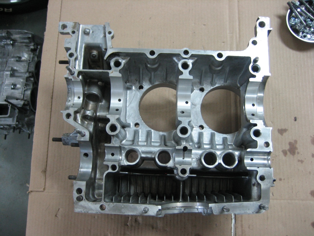
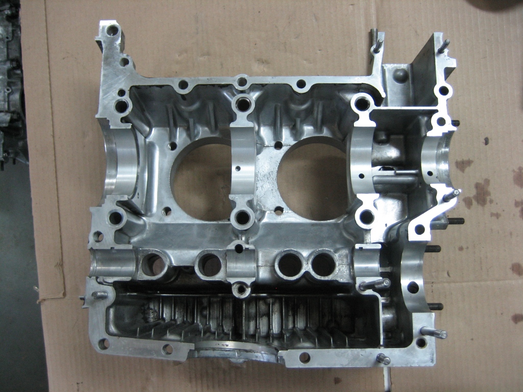
Before semi-retirement I built Rolls Royce Merlin V-12 engines and large Curtiss Wright 18 Cylinder radial engines for unlimited airplane racing. The tooling available that I was looking at was in my opinion substandard for the result I wanted. Even well known Type IV builders regarding line boring the Type IV case suggested finding one that did not need to be line bored. So as I did with the aircraft engines when a challenge came along, I studied the process, looked at what was being done and what it was going to take to get the result I wanted to achieve. So I made a new boring bar out of very stable linear way tool steel I made it as large as possible allowing the best available 90 degree cutting plane, Hard chromed the wear areas, used the highest quality indexable carbide boring tooling available and built a new bar with tapered expandable colletts on each end to locate the bar accurately. The total run-out on each of the expandable colletts was less than .0001 thousandths of an inch. I have done several cases up to this point with excellent results. I thought possibly it was time to explain this, and perhaps you will all understand the reason for the pricing. I also made the tooling for cutting the cylinder registers while torqued to a plate so the torque stresses are correct for those areas also.
The tooling laid into a case to show it's fitment.
John
Posted by: Cairo94507 Jan 17 2016, 08:30 AM
Wow. That's the way to do it. 
Posted by: sdoolin Jan 17 2016, 06:15 PM
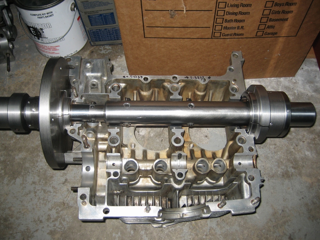
Today's progress. Cleaned case halves (to the best of my abilities)...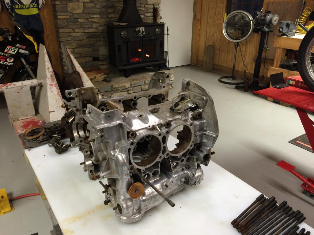
Crank doesn't look too bad...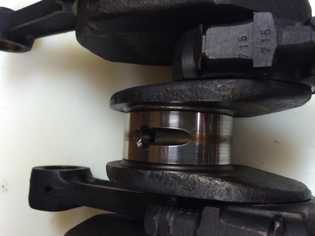
Next step is to send these case halves out to a pro for measuring and align-boring and decking (if needed)...
Posted by: sdoolin Jan 17 2016, 06:19 PM
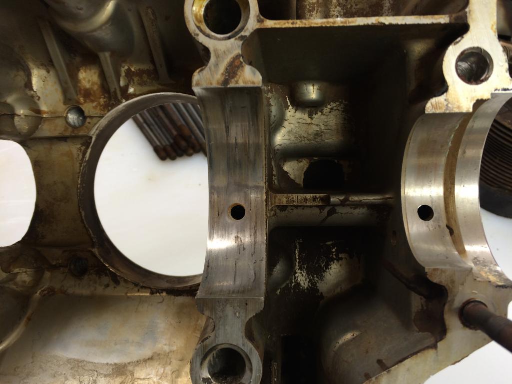
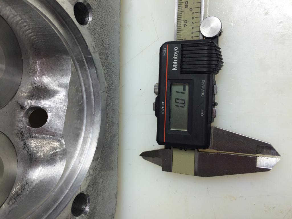
Unusual damage to #4 cylinder deck. I must not be the first one in here which is a little strange because this engine came from a single owner bus that I purchased 30 some years ago...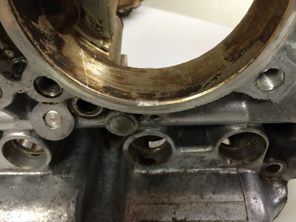
Posted by: sdoolin Jan 17 2016, 06:23 PM
Case halves don't look too too bad...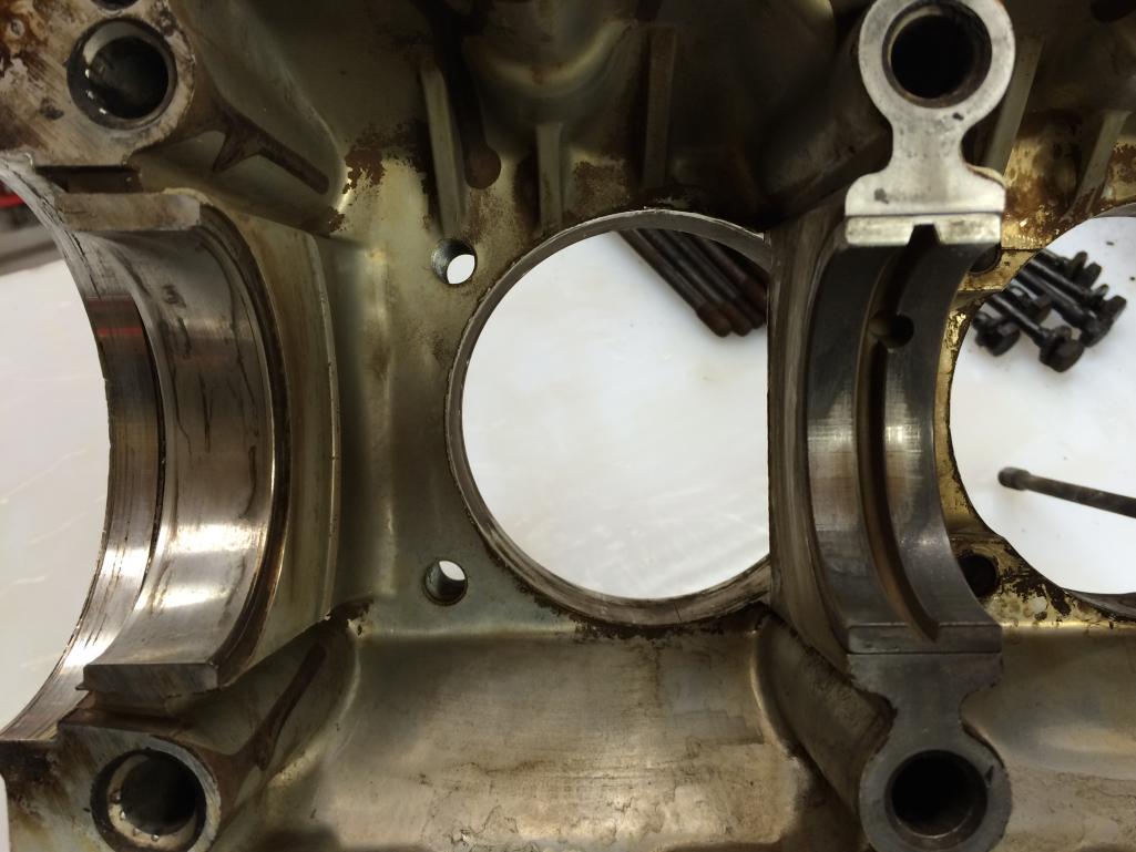
Posted by: sdoolin Jan 24 2016, 08:45 AM
Still looking for an East coast/local shop to measure and machine my cases, looks like I may have to send them out West (Jesco Reient).
In the mean time I have been researching valvetrain set up. Have read all that I can on 914world (searches on "valvetrain geometry" yield 4 - 5 decent results) and these threads generally reference Raby's article(s) on this subject. Which I can't seem to find. Which I am SURE I need to read.
Anyone have a link to that information?
Posted by: stugray Jan 24 2016, 11:35 AM
Anyone have a link to that information?
PM sent
Posted by: wndsrfr Jan 24 2016, 07:00 PM
Still looking for an East coast/local shop to measure and machine my cases, looks like I may have to send them out West (Jesco Reient).
Len Hoffman......here's a link: http://www.hamincgroup.com/services.php
Posted by: sdoolin Jan 25 2016, 06:56 AM
Still looking for an East coast/local shop to measure and machine my cases, looks like I may have to send them out West (Jesco Reient).
Len Hoffman......here's a link: http://www.hamincgroup.com/services.php
Thanks for the tip. I emailed Len about a week ago and have not heard back from him. So - still looking...
Posted by: sdoolin Jan 27 2016, 09:07 AM
Update - cases are out being measured (crank bore & cylinder decks). Jugs are also in shop for boring to accept 96mm peestons.
Reading - reading - reading...
My "kit" from Type IV Store includes the 911 swivel feet valve adjusters/nuts along with rocker shafts/studs. I did not order an adjustable pushrod from them - but will do so before I get to that stage of the build.
To use the swivel feet adjusters I believe (OK - I KNOW) I will need 1.7 rockers (and they will need to be modified). Best place for these? Just place a WTB in classifieds?
Posted by: Java2570 Jan 27 2016, 11:13 AM
You might check with Brad Mayeur at 914 LTD about the 1.7 rockers....I got a set from him. http://914ltd.com
Posted by: sdoolin Jan 27 2016, 02:36 PM
You might check with Brad Mayeur at 914 LTD about the 1.7 rockers....I got a set from him. http://914ltd.com
Thank you - sent them an email.
Posted by: sdoolin Feb 3 2016, 08:57 PM
So the news is in...
My local guy says that these cases do NOT need align bored or decked. I imagine this is hard to believe?
Posted by: sdoolin Mar 4 2016, 04:57 PM
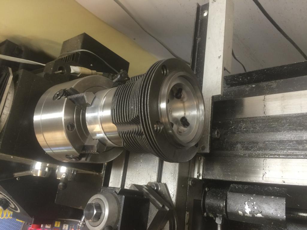
Just received a pair of HAM RS+ Spec Cyl. Heads. Those of you that have observed these beautiful pieces know how sweet they are, and how well they work. Cases are ready for me from local machine shop and I will pick-up Monday. So I can begin (again) the build.
2 Beautiful new heads...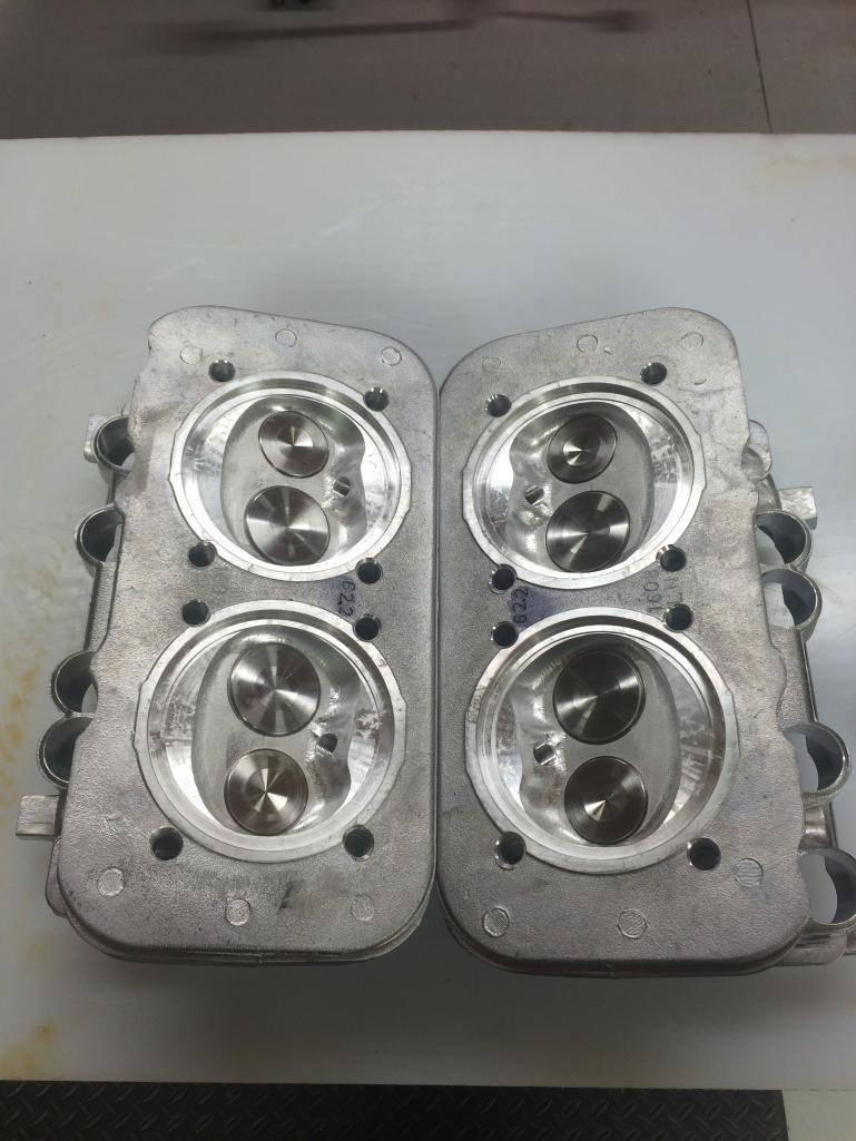
Old/Stock head vs HAM RS+ note the squish/quench area differences, plug hole has been re-angled for chamber shape...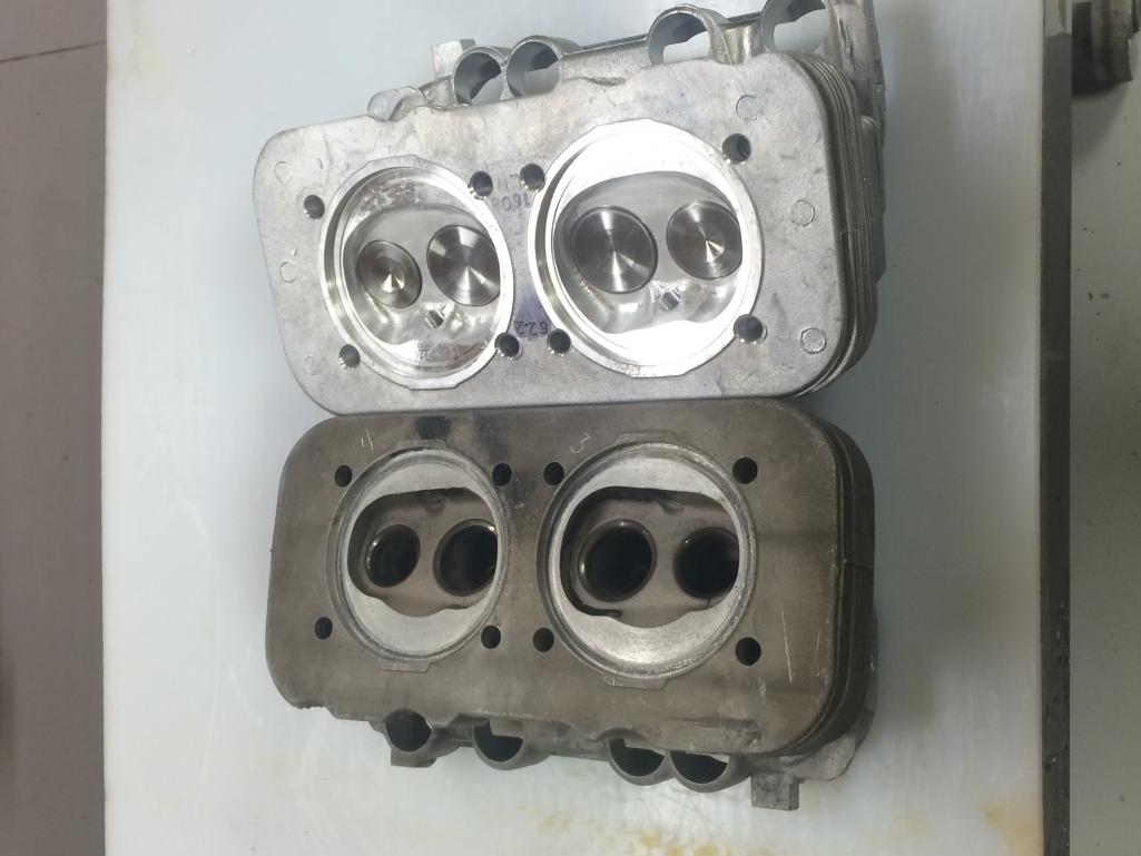
Posted by: sdoolin Mar 4 2016, 05:04 PM
More RS+ Porn...
Notice the machinng/work done at the intake manifold surface...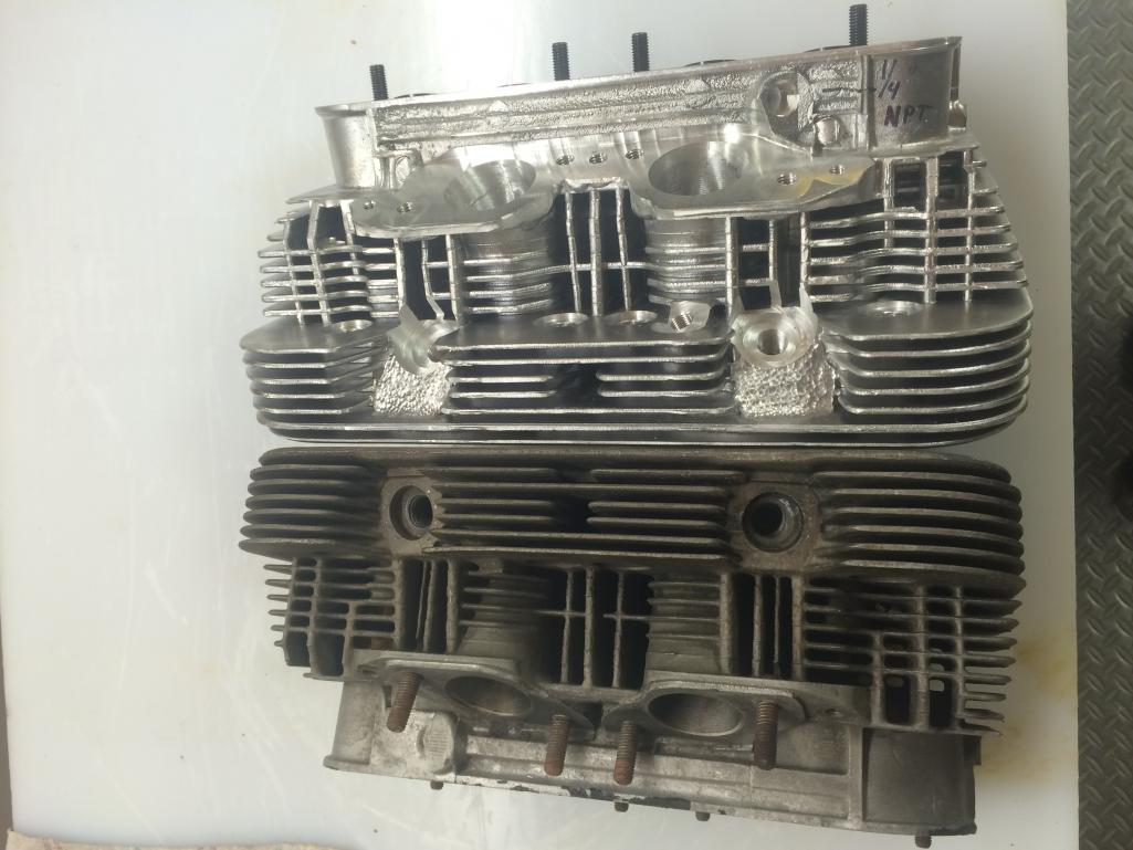
Work done to re-angle spark plugs...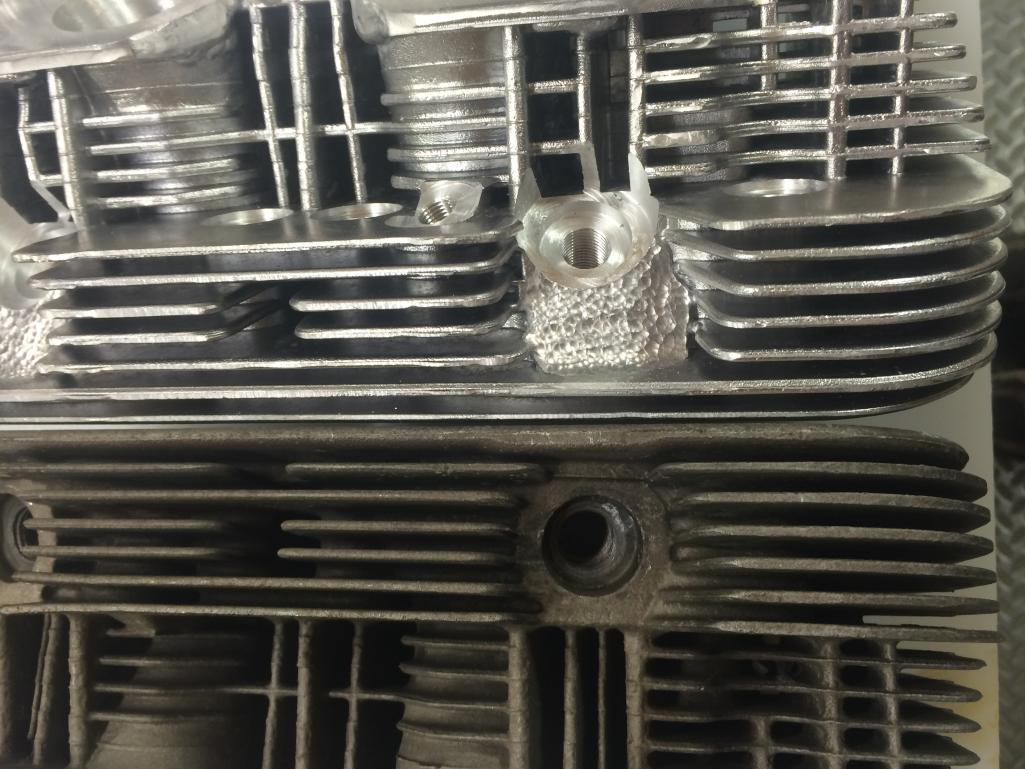
Posted by: Dave_Darling Mar 4 2016, 07:06 PM
Does he mean your specific case, or all Type IVs in general?
Conventional wisdom used to be that they didn't need align-boring. They are, after all, built tougher than the magnesium Type I case, which is pretty much always align-bored out of hand--because just about all of them need it. So we got used to saying, "These don't usually need it, check before you cut, OK?"
That was a couple decades ago, though. Now they've run more miles and have more heat cycles and seen more wear. More than a few do need align-boring. It is best to have the case checked.
--DD
Posted by: sdoolin Mar 4 2016, 07:35 PM
He means my specific case. He measured the crank bore and the cylinder decks and he says all OK. He is balancing all moving parts (crank/rods/pistons), verifying all cylinder/head bolt threads are good (it came apart well), installing new threaded galley plugs and generally cleaning the cases up. I get it all beck next week.
Then the real fun begins...
Posted by: sdoolin Mar 4 2016, 07:41 PM
Also, this set of cases hasn't seen a crankshaft turn in them for at least 20 years (closer to 30), so do not have the wear and tear or heat cycles that would've been associated with those years of operation.
Posted by: sdoolin Mar 11 2016, 06:51 PM
So I finally picked up my cleaned/measured cases/crank and rods. Doing pre-assembly tonight. What is the conventional wisdom on re-installing the cylinder/head studs into the cases? Threadlock (Loctite) or no threadlock?
I have built 3 bus engines and have never used threadlock on the cylinder/head studs, but then I've never removed them in those builds. My thought has always been less threadlock is better, but I want to build this engine the best I can.
Is there a torques spec for installing the cylinder/head studs?
All opinions appreciated (I think)...
Posted by: stugray Mar 11 2016, 07:08 PM
Right off the top of my head:
You will almost certainly take the case halves apart many times, so dont use any sealant on the mating halves till youre sure.
The #1 mistake made is letting the bearings come unseated from the dowel pins that hold the bearings. This results in brand new, ruined bearings.
As you torque the sides together rotate the crank & cam they should turn like butter even at full case torque.
Once you have the rods attached, be careful when you rotate the assembly and dont let the rods slap on the case.
Once you have the jugs on you will be measuring your deck height.
I have an old thread where I struggled with this for a long time before getting it right. I'll see if I can dig it up.
There are some tools provided by a member on this site (yeahmag) that makes the measurement 'almost' idiot-proof.
Here it is:
http://www.914world.com/bbs2/index.php?showtopic=196177
Posted by: sdoolin Mar 11 2016, 08:39 PM
Yes, thanks for all of that (no disrespect intended). I have built a few of these engines for buses, so am familiar with the basics of crankshaft build-up and case mating. Definitely want things to spin free.
My specific question has to do with the long studs for the cylinders/heads. I removed them from the case halves before I sent them (the case halves) for measurement. Now, on re-assembly, is there a torque spec to re-install them to the cases, and, do we all think that threadlock is required for these? The cases have excellent threads and no helicoils were needed (as is often the case with type I engines).
I generally avoid threadlock where possible, but not sure if these should be "loctited" or not. They have very nice "bite" into the threads/cases.
Posted by: sdoolin Mar 12 2016, 08:53 AM
Hope to have the cases all assembled by the end of this weekend. Crankshaft was balanced, rods were balanced (big-ends and small-ends), and new KB 96mm pistons were weight matched.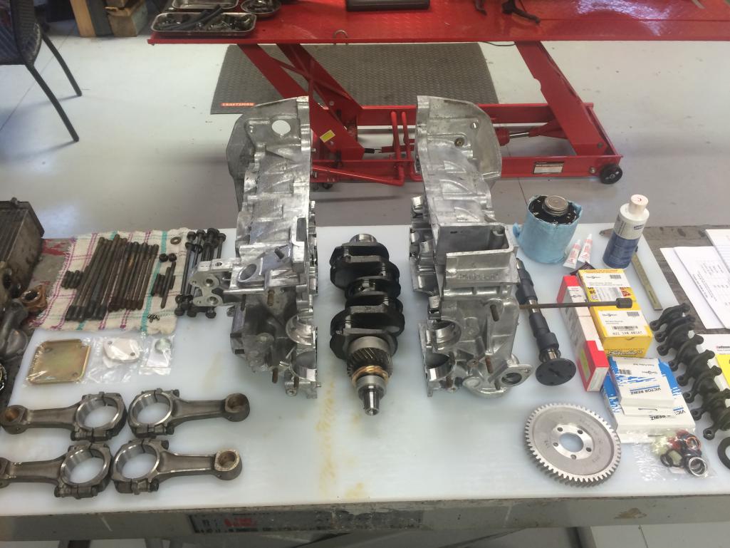
Then working out of town for a week, then next weekend hope to work on deck height and compression ratio...
Posted by: sdoolin Mar 12 2016, 12:11 PM
Oil Dipstick Tube fitment. Bus engine cases need to be drilled. I am using 5/16" hydraulic brake line press fit into a 5/16" hole in the case. Will secure with some JB Weld (or other) when complete.
Anyone know exact height of dipstick tube from top of case to top of tube?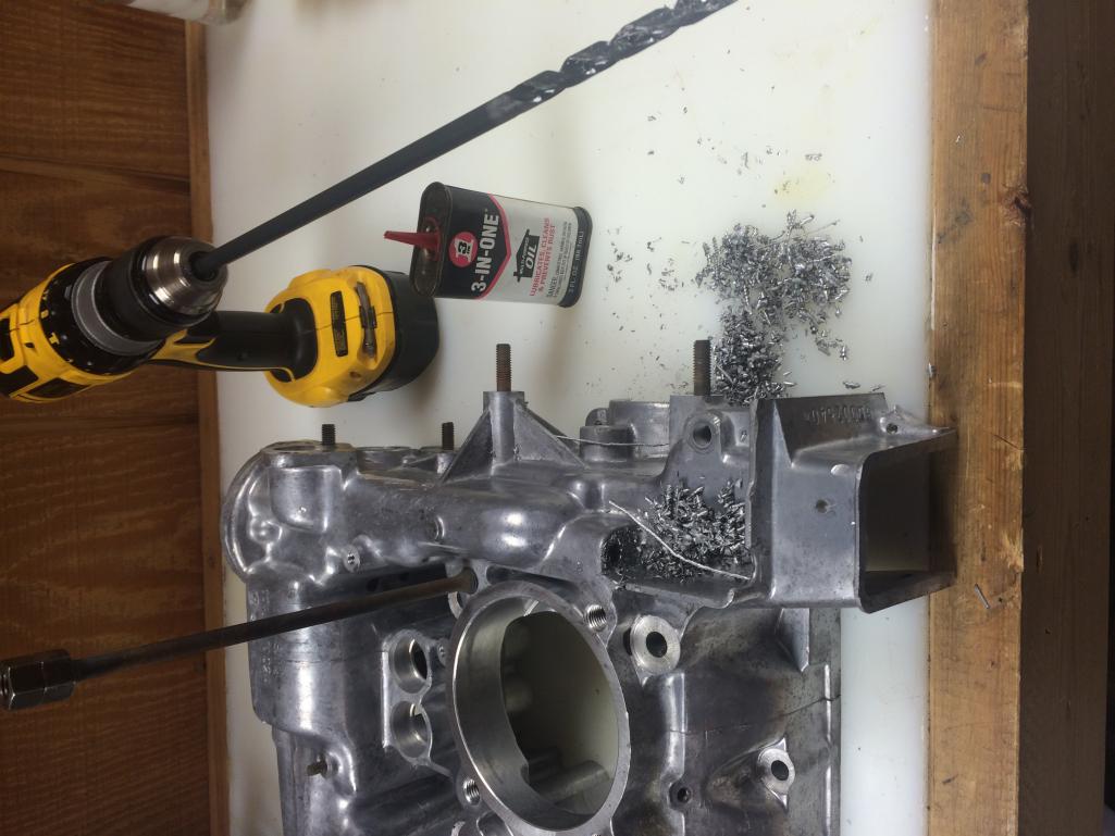
Accomplished on the crude side of the shop, but I am comfortable with the solution...
Posted by: wndsrfr Mar 12 2016, 01:05 PM
Oil Dipstick Tube fitment. Bus engine cases need to be drilled. I am using 5/16" hydraulic brake line press fit into a 5/16" hole in the case. Will secure with some JB Weld (or other) when complete.
Anyone know exact height of dipstick tube from top of case to top of tube?
I'm seeing 85 mm on a known stock case....3 & 3/8" .....
Posted by: sdoolin Mar 12 2016, 04:23 PM
Thanks for that, but that measurement appears too small. On my cases 3 & 3/8 will not clear the oil fill/breather box and on the engine in my car the dipstick tube def clears that breather (the metal box bit, not the plastic filler neck).
I am at a full stop unfortunately as both of my new double thrust cam bearings (from Type IV Store) have locating tangs, and my case does not have a locating tang space on the right hand case (cyl 3 & 4). Very strange.
I had hoped to get it all bolted together this weekend, but no love.
Posted by: Valy Mar 12 2016, 09:11 PM
One more thing you MAY want to change on that case:
If you're going to fit an oil temp sensor in the taco plate (original sensor), then check that it fits now. Some cases, and this includes some bus cases, have a lip there that needs to be removed for the long sensor to fit. Some are ok. I don't know when the change happened.
I don't have a picture right now but please check and you'll see what I'm talking about.
Posted by: Valy Mar 12 2016, 09:14 PM
One more thing you MAY want to change on that case:
If you're going to fit an oil temp sensor in the taco plate (original sensor), then check that it fits now. Some cases, and this includes some bus cases, have a lip there that needs to be removed for the long sensor to fit. Some are ok. I don't know when the change happened.
I don't have a picture right now but please check and you'll see what I'm talking about.
Here it is:
http://www.914world.com/bbs2/index.php?s=&showtopic=142833&view=findpost&p=1558181
Posted by: sdoolin Mar 13 2016, 08:44 AM
One more thing you MAY want to change on that case:
If you're going to fit an oil temp sensor in the taco plate (original sensor), then check that it fits now. Some cases, and this includes some bus cases, have a lip there that needs to be removed for the long sensor to fit. Some are ok. I don't know when the change happened.
I don't have a picture right now but please check and you'll see what I'm talking about.
Checked the taco plate location on these cases. All good, long sensor oil temp will fit. Thanks for the heads-up on that.
Posted by: sdoolin Mar 25 2016, 11:03 AM
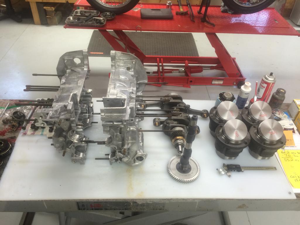
Finally ready to assemble cases. Don't think I'll get Ps & Cs done today, just the crank, cam, oil pump, etc.
Posted by: sdoolin Mar 25 2016, 06:28 PM
Cases reunited. Hardest bit was the oil pickup because, well, I left it out first attempt. Realized it when I had a single M10 thoughbolt snugged up. Tried again and tightened 2 of the M10s until I remembered to "locate" the pickup with its own through bolt.
Finally all together. All bolts torqued nicely, oil pump went in without an argument and I'm not bleeding anywhere. I call this a success.
I consider this the easy bit with the rest getting more complicated. Deck height and CR must be checked and set, and then valvetrain geometry fun after that. 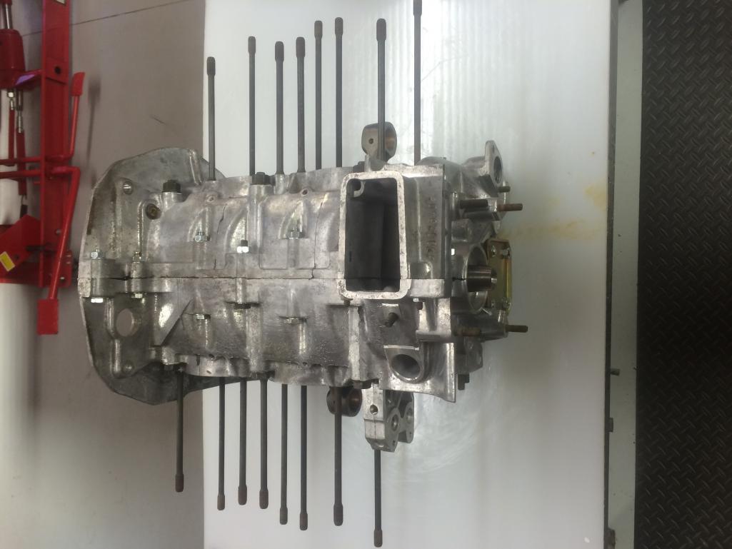
Posted by: Bleyseng Mar 26 2016, 10:58 AM
Why are you using a bus case?
Posted by: sdoolin Mar 27 2016, 07:51 AM
Why are you using a bus case?
Because it was there?
Posted by: cgnj Mar 27 2016, 08:49 PM
Why are you using a bus case?
Because it was there?
It's in his hands. If I had a dime for every dollar I spent doing the "right thing" for my teeners, I'd have a 911 in the garage, next to the 928s and 914s (none of these are a "real" Porsche. Keep the recipts and pics and source a case later. The longer a project sits, the more likely it is a barn find. Get it back on the road.
Back in the Stone Age Mallory Unilite, grey/grey springs. Apparently sold. Now made in China. You can get one from Tangerine Racing ready to go. Otherwise call john @ aircooled.net amd get his recurved svda distributor.
Posted by: Tbrown4x4 Mar 30 2016, 06:16 PM
Loving this thread! I have some 2.0 bus parts at the machine shop now for a 2056 build.
I was under my '73 the other day and noticed how close the engine bar comes to the 1.7 case where the bus oil fill would be. My bus engine came out of a '71, so the engine bar is smaller. I'm worried the block-off plate and studs in the bas case are going to hit the '73 engine bar, so I'm going to countersink the cover and use countersunk machine screws to hold the cover in place to try to get some clearance. Thought I'd give you a heads up about it. I saw the block-off plate in your pictures and the "1973 914" in your sig. Sounds like we're doing the same swap! 
Posted by: 76-914 Mar 31 2016, 08:14 AM
![]()
Posted by: sdoolin Mar 31 2016, 10:16 AM
Loving this thread! I have some 2.0 bus parts at the machine shop now for a 2056 build.
I was under my '73 the other day and noticed how close the engine bar comes to the 1.7 case where the bus oil fill would be. My bus engine came out of a '71, so the engine bar is smaller. I'm worried the block-off plate and studs in the bas case are going to hit the '73 engine bar, so I'm going to countersink the cover and use countersunk machine screws to hold the cover in place to try to get some clearance. Thought I'd give you a heads up about it. I saw the block-off plate in your pictures and the "1973 914" in your sig. Sounds like we're doing the same swap!
Thanks for the heads-up. If you get around to this before I do - post some pics please. My car has a running engine in it (I am still driving it) so I won't be sure if the engine mounting hardware will all bolt up until I am ready to install this thing.
Posted by: sdoolin Mar 31 2016, 10:48 AM
Getting ready to measure Deck Height, and then set CR. Using a tool for Deck Height measurement made for Type I's. I will weld on an additional steel plate so that I will get even/appropriate clamping forces on all four studs/corners.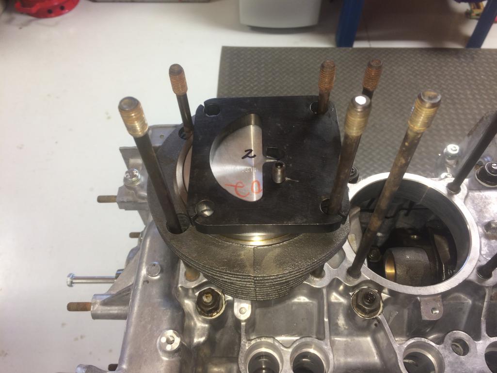
The screw in center(ish) of this plate is calibrated such that 1 full turn = 1mm. So with this tool I can use the calibrated screw to take a number, I can use feeler gauges to take a number, and I can also use a dial indicator (once I weld on the additional plate) to take a number.
I just hope (pray actually) that all the numbers are the same (or very very close).
That calibrated screw is not directly over the wrist-pin I know, but I am comfortable with this approach. No shim/gasket between jug and case, and a single piston ring installed.
Posted by: sdoolin Apr 4 2016, 06:41 AM
Having measured deck-height over the weekend I (naturally) have questions. I used the tool pictured previously with the calibrated screw. The directions indicate 1 full turn = 1mm (which I measured and verified).
On cyls 1 & 2 I get a deck height measurement of 1mm using the calibrated screw, and some stacked up feeler gauges yield the same measurement. Did not measure the other side yet. I can tell that actual deck height is just a bit less since that calibrated screw (and feeler gauges) rock the piston ever so slightly. But - I am comfortable (for now) with a repeatable measurement of 1.0 mm (.039).
Plugging bore (96mm), stroke (71mm), deck height (.039) and chamber volume (55.2) into the CB Perf. engine calculator it yields a CR of 9.3 - 1. Is that too much?
When I first began this project a couple of months ago Jake posted a quick reply that I'm using pretty much all the right bits and pieces and I should se the CR at 9.0 - 1. I tend to believe that guy.
Without starting a flame war (if you are just going to bash JR, or this build don't bother posting) - how do we feel about a CR just a tad higher than 9.0 - 1? I'd love to bolt up the short block without any shims under the jugs and leave this CR alone, but am interested in experienced opinions from those who have done this (or a similar) build.
All meaningful replies much appreciated.
Posted by: wndsrfr Apr 4 2016, 07:22 PM
Oil Dipstick Tube fitment. Bus engine cases need to be drilled. I am using 5/16" hydraulic brake line press fit into a 5/16" hole in the case. Will secure with some JB Weld (or other) when complete.
Anyone know exact height of dipstick tube from top of case to top of tube?
I'm seeing 85 mm on a known stock case....3 & 3/8" .....
Whoops....that 85mm is from the flange that the tin mounts against....from the case top it's 6 inches.....152mm. That's what I used on my 2316....
Posted by: Bleyseng Apr 5 2016, 09:54 AM
Toss the VR rear main oil seal and get the Sabo seal from GoWesty as it actually seals the flywheel vs the VR seal which leaks.
Posted by: sdoolin Apr 9 2016, 10:26 AM
More deck height and compression ratio questions (really the same one but I never got a response(?)).
I have measured and re-measured deck height on all 4 cylinders. All come up with 1mm deck height in the jug. I got sage advice from HAM that there is 1mm of step (deck height) in my cylinder heads. This gives me a total deck height of 2mm.
I am targeting 9:1 Compression ratio. Plugging the numbers into CB's engine calculator and solving for deck height it yields 1.28mm for a CR of 9:1.
So I need to remove 2.00mm - 1.28mm = 0.72mm.
I'm pretty comfortable with my measurements and with this math.
My question (finally) - can I remove 0.72mm from the jug, or do I need to remove it from the head?[i] It'd be much easier for me to remove it from the jug, so I'd prefer that, but if the conventional wisdom is against that, then I'll send the heads out.
If it is OK to remove this material from the jugs I could get it done this weekend and complete the short block...
As always - thanks in advance for all assistance.
Posted by: stugray Apr 9 2016, 11:29 AM
I got sage advice from HAM that there is 1mm of step (deck height) in my cylinder heads. This gives me a total deck height of 2mm.
I am targeting 9:1 Compression ratio. Plugging the numbers into CB's engine calculator and solving for deck height it yields 1.28mm for a CR of 9:1.
If the heads have a 1mm lip, did you account for that in your combustion chamber number?
Or did you measure the comb. chamber volume?
You comb chamber number seems smaller than a stock head.
I had to shave my heads down significantly to get below 55 cc.
Stock is almost exactly 60 cc.
Posted by: sdoolin Apr 9 2016, 11:43 AM
I got sage advice from HAM that there is 1mm of step (deck height) in my cylinder heads. This gives me a total deck height of 2mm.
I am targeting 9:1 Compression ratio. Plugging the numbers into CB's engine calculator and solving for deck height it yields 1.28mm for a CR of 9:1.
If the heads have a 1mm lip, did you account for that in your combustion chamber number?
Or did you measure the comb. chamber volume?
You comb chamber number seems smaller than a stock head.
I had to shave my heads down significantly to get below 55 cc.
Stock is almost exactly 60 cc.
I did account for the 1mm step in the heads in my combustion chamber number, or rather Len did at HAM. I did not CC the heads myself, that was done by Len at HAM. The spec sheet that came with the heads says the chambers are 55.2 CC. I am pretty sure Len's number is accurate. Much more so than mine.
Posted by: sdoolin Apr 10 2016, 07:59 AM
I am taking .72mm off the top of the jugs today. Should be a good time.
Posted by: sdoolin Apr 11 2016, 06:14 AM
Toss the VR rear main oil seal and get the Sabo seal from GoWesty as it actually seals the flywheel vs the VR seal which leaks.
Ordered Sabo seal from GoWesty last night - appreciate the heads up.
Posted by: MarkV Apr 11 2016, 08:40 AM
Are you sure about the size of your chambers? When I did mine they were in the 59cc range. Did you do the whole clear plastic disc and burette thing. It's been a while since I did mine but I had to use spacers that I ordered from aircooled.net under the cylinders. I ended up with 9.5 : 1 compression and it runs fine on regular fuel.
Posted by: sdoolin Apr 11 2016, 08:58 AM
Are you sure about the size of your chambers? When I did mine they were in the 59cc range. Did you do the whole clear plastic disc and burette thing. It's been a while since I did mine but I had to use spacers that I ordered from aircooled.net under the cylinders. I ended up with 9.5 : 1 compression and it runs fine on regular fuel.
I did not CC the heads myself - but have been through the process for other engines. These heads are the RS+ specification heads from HAM (Len Hoffman). They came with a spec sheet that includes the combustion chamber volume. I trust the numbers from Len.
Posted by: MarkV Apr 11 2016, 09:10 AM
Len did my heads too. I measured them to make sure everything matched on all 4 cylinders. My finished deck height with spacers was .014 with a combustion chamber of 59cc my exact compression ratio is 9.3 to 1.
Posted by: stugray Apr 11 2016, 01:29 PM
So I did the calcs myself and got 8.37CR with a 2mm deck height which agrees pretty well with the CB calculator.
on the CBPerf website, When I plug in 96 bore, 71 stroke, comb chamber 55.2, compression ratio 9.1, and click solve for deck height I get 1.17mm.
So your target of 1.28mm will get you to 9.0:1 CR.
And sorry if I missed it, I assume you will run with no head gaskets?
Posted by: stugray Apr 11 2016, 01:36 PM
Len did my heads too. I measured them to make sure everything matched on all 4 cylinders. My finished deck height with spacers was .014 with a combustion chamber of 59cc my exact compression ratio is 9.3 to 1.
Are you certain your final deck height was .014?
From what I recall from research is that you should not have a deck height of less than .025 (.65 mm Min) to allow for piston expansion.
I am sure it depends on the specific piston material, but that was a rule of thumb that you supposedly should not cross without knowing what you were doing.
I was trying to get maximum CR on my build and had the engine assembled with .024 DH, and chickened out and tore the engine back down and increased to more like .030.
Posted by: sdoolin Apr 11 2016, 01:39 PM
No head gaskets...
Posted by: MarkV Apr 11 2016, 03:11 PM
The deck height of .014 was before I added a .020 spacer. And my 59cc was before I decided to send my heads to Len to have them rebuilt. He welded up the spark plug holes and changed them to 12mm. I can find my notes for the finished head combustion chamber after Len rebuilt them. I know my compression ratio is a little more than 9:3 and I was worried about it being to high at the time.
Posted by: sdoolin Apr 11 2016, 05:35 PM
I decided I always need to know where my crank is - I mean - that's just a good idea...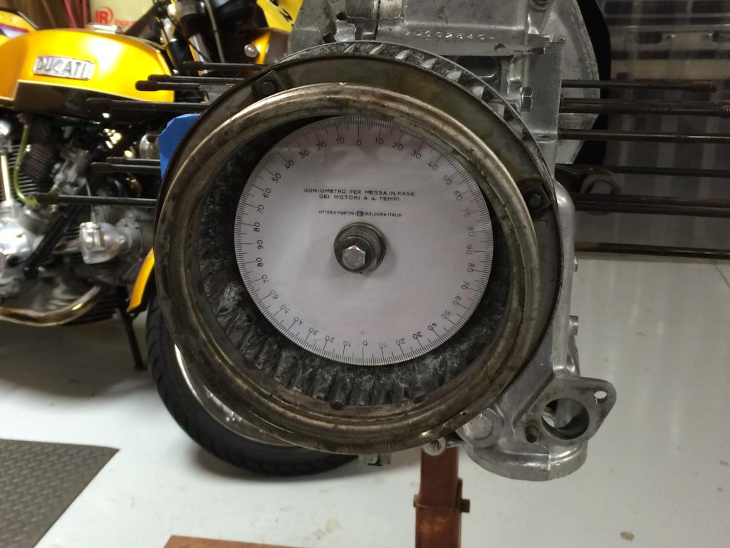
Degree wheel is an old Ducati piece. Where we say "degree wheel" the Italians turn it into a song and say "goniometro per messa in fase dei motori a 4 tempi". I mean, it says it right on there. Rough translation = "goniometer for commissioning phase of the 4-stroke engines".
"Commissioning phase" - I like that...
Posted by: MarkV Apr 11 2016, 05:39 PM
So disregard pretty much everything I said. I found a photo of my heads after I got them back from Len. When he finished I had a 60cc combustion chamber. Jake bored my factory jugs to 96mm and with KB flat top 96mm pistons the deck was .014 and with a .020 spacer and no head gasket that put my compression ratio at 8.8:1. My OEM cylinders must be shorter than what you are using. I used short peices of tubing and snugged the head bolts to hold the cylinders in place before I took measurements. I had to swap cylinders around and clean some minute gasket material off the registers until I got both banks to have equal pre and post spacer deck height. I also had to sand the spacers with oil and wet/dry sand paper. Both banks weren't the same but both pairs matched when I finished.
Attached image(s)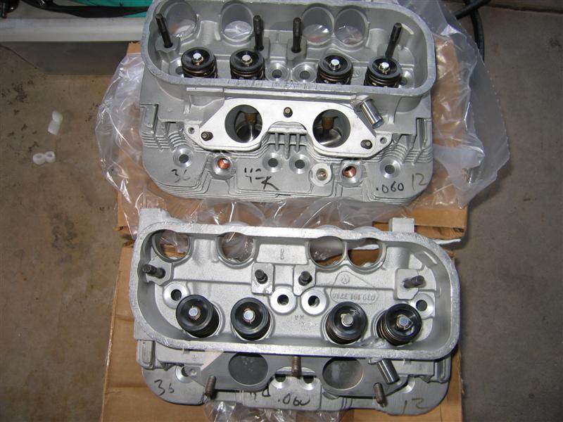
Posted by: sdoolin Apr 11 2016, 05:43 PM
More fun finding TDC on #1. This fan from a bus (of course) so no marks on the fan itself, just a single mark on the pulley. That mark lines up at about 32 BTDC - which I think makes sense for a bus. You can barely see that mark (white dot) in the second image. Of course my pics will be rotated to appear as if I may have been standing on my head when I snapped them...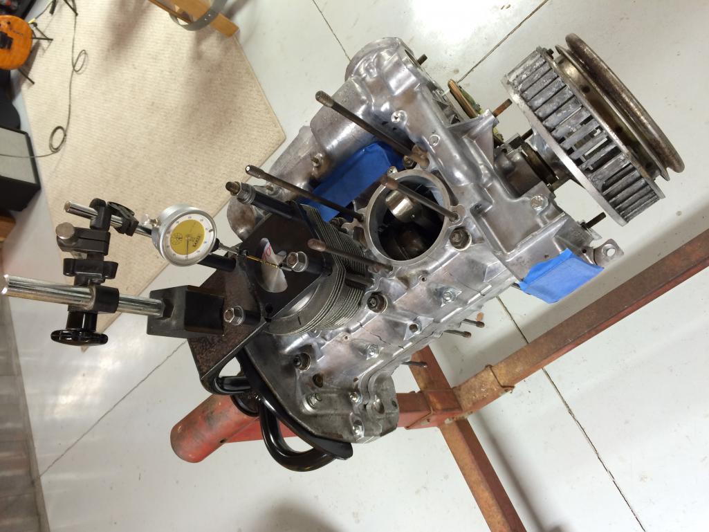
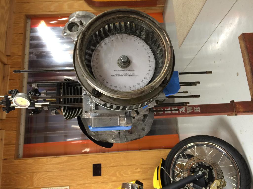
I suppose I need to make some marks so I can time this thing from the top through the timing sight in the fan shroud....
Posted by: stugray Apr 11 2016, 07:43 PM
I suppose I need to make some marks so I can time this thing from the top through the timing sight in the fan shroud....
I time my engine from the rear using the flywheel marks.
There is (should be) a machined notch with white paint at TDC #1.
I made a yellow mark 180 degrees from that.
I can time my engine with the white mark thru the hole in the top front of the trans case, and I can set my valves from underneath using the white & yellow marks alternating as I rotate for each set of valves.
You can see the white mark here:
https://www.youtube.com/watch?v=QtPd5qzyTk8
I dont use the marks on the fan for anything anymore.
Posted by: Dave_Darling Apr 11 2016, 08:49 PM
First: I would try to quantify the effect on deck height measurement of rocking the piston in the bore. You might find it is significant, or you might find it is not so.
Second: Removing material from one or both ends of the cylinder will raise the compression, not reduce it.
Third: If Jake, who designed the cam profile and had input on the chamber shape and porting, says you should target 9:1, I would do what I can to get as close as possible to 9.000:1.
--DD
Posted by: sdoolin Apr 12 2016, 06:15 AM
First: I would try to quantify the effect on deck height measurement of rocking the piston in the bore. You might find it is significant, or you might find it is not so.
Second: Removing material from one or both ends of the cylinder will raise the compression, not reduce it.
Third: If Jake, who designed the cam profile and had input on the chamber shape and porting, says you should target 9:1, I would do what I can to get as close as possible to 9.000:1.
--DD
First - I did attempt to quantify piston movement during deck height measurement. I would raise the piston in the bore until it just kissed my calibrated screw, not enough to move/rock the piston. Then lower piston, turn screw 1/4 turn (.25mm) then raise piston again. In all instances the 1/4 turn was too far, essentially using up all available piston "rock" and stopping the piston before it reached TDC (engine would not turn any farther). So - piston rock less than .25mm and my deck height (in the jug) of 1.0mm seems accurate.
Second - agree, I am removing .72mm in an attempt to raise the compression ratio to 9.0:1.
Third - COMPLETELY agree.
Thanks for the input DD.
Posted by: sdoolin Apr 28 2016, 06:42 AM
More progress. Have spent the better part of a week fabricating a fixture to take material (.72mm) off the top of the jugs in order to get the CR desired.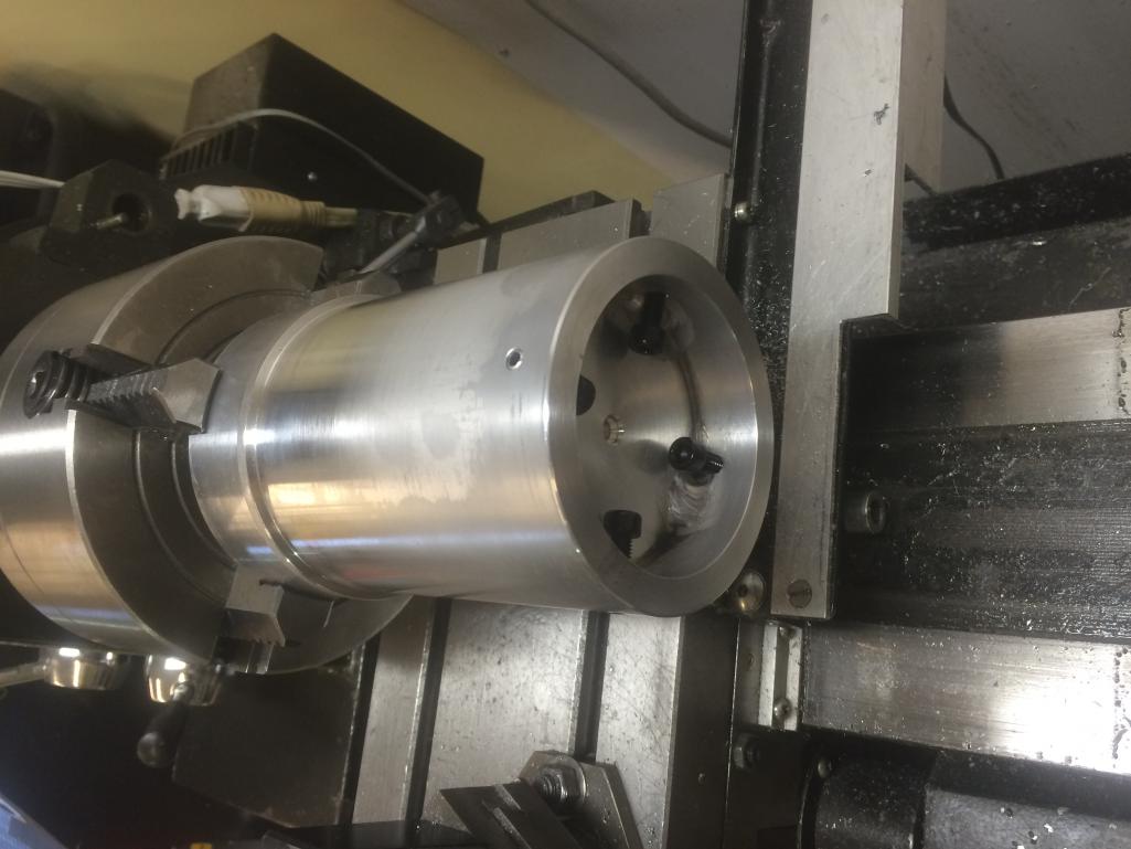
The jugs is very nearly an interference fit onto the fixture, and slides down to a shoulder to ensure all is true. Will use the tailstock on the lathe to make things even more secure/stabil when making the cut to the jugs. There are 4 aluminum set screws on the inside of the fixture to secure the jug. Is this overkill - YES. But all will be very true, and very much the same once completed.
Posted by: sdoolin Apr 30 2016, 10:41 AM
Never drop a brand new cylinder (or any other cylinder you might want to use). I turned down 3 of 4 cylinders using my wayoverthetop fixture, then tripped slightly on a dogs leash in my buddy's shop allowing the fourth cylinder to escape my grasp.
Damaged the skirt ever so slightly and it will not slip over my wayoverthetop fixture.
Anyone have a single 96mm cylinder laying around that they feel the need to part with?
Posted by: wndsrfr Apr 30 2016, 07:25 PM
Never drop a brand new cylinder (or any other cylinder you might want to use).
Anyone have a single 96mm cylinder laying around that they feel the need to part with?
Yep, got a box with 4 of them that may work for you just gathering dust....I'll ship them to you & you can decide to pay whatever is fair IF you can use one & you hang on to the rest for the next unlucky dude. PM me your address--
Posted by: sdoolin May 1 2016, 07:38 AM
Never drop a brand new cylinder (or any other cylinder you might want to use).
Anyone have a single 96mm cylinder laying around that they feel the need to part with?
Yep, got a box with 4 of them that may work for you just gathering dust....I'll ship them to you & you can decide to pay whatever is fair IF you can use one & you hang on to the rest for the next unlucky dude. PM me your address--
I love this place. PM sent wndsrfr.
Posted by: stugray May 1 2016, 10:43 AM
Nice setup for trimming. I wish I had a machine shop at my disposal.
One thing keeps nagging me. Why have I NEVER seen someone else ever trim the jugs like this?
This is the first time I have ever heard mention of it.
I have 9.5:1 and didn't have to trim my jugs.
I think that lip on the heads is what killed you.
Posted by: sdoolin May 2 2016, 06:27 AM
Stugray - I agree about trimming the jugs. I asked quite a few times about it in this thread, got no real response. In all of my reading/research, material was removed from the heads to raise compression, never the jug(s) - which is why I asked so many times.
I bolted the heads up and measured clearance before deciding to go this route. Head - Jug clearance with everything torqued to spec was 1.25mm, so removing .72mm from the top of the jugs should not (I pray) create an issue there. Perhaps the 1mm step in the heads is the reason, not sure.
All clearances will get very carefully measured as it goes together.
I just gotta try not to drop anything else important...
Posted by: wndsrfr May 2 2016, 06:56 PM
Never drop a brand new cylinder (or any other cylinder you might want to use).
Anyone have a single 96mm cylinder laying around that they feel the need to part with?
Yep, got a box with 4 of them that may work for you just gathering dust....I'll ship them to you & you can decide to pay whatever is fair IF you can use one & you hang on to the rest for the next unlucky dude. PM me your address--
I love this place. PM sent wndsrfr.
OK....jugs went out via Priority Mail today, prolly be there Wed....
Posted by: sdoolin May 4 2016, 10:11 AM
Thanks wndsrfr. Let me know what the shipping was.
Is there an official opinion on cylinder - piston clearance? I am measuring .002 and well, that seems very tight. I have already gapped my ringset (.020 top, .015 second), but if I need to hone the jugs for more clearance I will source another set (of rings).
And I thought I'd have this thing built by now.... 
Posted by: wndsrfr May 5 2016, 10:20 AM
Thanks wndsrfr. Let me know what the shipping was.
Is there an official opinion on cylinder - piston clearance? I am measuring .002 and well, that seems very tight. I have already gapped my ringset (.020 top, .015 second), but if I need to hone the jugs for more clearance I will source another set (of rings).
And I thought I'd have this thing built by now....
Was there a sheet that came with the pistons telling about p/c clearance? Are you using KB hypereutectic or J&B forged?
Here's a link to clearances--I used the "Baja aircooled" recommendation on my build.
http://www.hughesengines.com/TechArticles/2clearancerequirementsforhypereutecticpistons.php
Don't sweat shipping til you know if the jugs are useable...
Posted by: sdoolin May 29 2016, 09:37 AM
OK - so I had to take a break from this for a few weeks - other life priorities got in the way. I'm still not sure what I will do about the damaged jug - but should know this week. That means I will be able to finish the long block this week and then onto valve train geometry (yes, I said that back in February also).
Still no adjustable pushrod from Type IV Store, so I need to sort that out.
Some questions...
Can I set crank thrust (end play) with the long block all bolted up or do I need to do that before I get pistons, cylinders and heads installed? Crank moves very freely for/aft before everything bolted up.
For ignition timing - I have been told by someone I trust to set initial advance at 14*, and full advance at 28*. But not sure if this is BTDC or ATDC. Does this mean I should make marks on my fan at those degrees of crank rotation (I have a degree wheel on the fan/crank) for use in timing later? I think yes, but would like other opinions.
I need a distributor. Curious about opinions on what to use and where to get.
Posted by: stugray May 29 2016, 10:32 AM
OK - so I had to take a break from this for a few weeks - other life priorities got in the way. I'm still not sure what I will do about the damaged jug - but should know this week. That means I will be able to finish the long block this week and then onto valve train geometry (yes, I said that back in February also).
Still no adjustable pushrod from Type IV Store, so I need to sort that out.
Some questions...
Can I set crank thrust (end play) with the long block all bolted up or do I need to do that before I get pistons, cylinders and heads installed? Crank moves very freely for/aft before everything bolted up.
For ignition timing - I have been told by someone I trust to set initial advance at 14*, and full advance at 28*. But not sure if this is BTDC or ATDC. Does this mean I should make marks on my fan at those degrees of crank rotation (I have a degree wheel on the fan/crank) for use in timing later? I think yes, but would like other opinions.
I need a distributor. Curious about opinions on what to use and where to get.
You can set the endplay with the engine finished and just before you bolt on the FW for the last time.
Timing is usually set to 5deg BTDC 'static' before you fire up the engine for cam breakin.
You wont be able to set it properly until after breakin.
I use the mark on the FW through the access hole on the top of the tranny and a variable timing light. For me it is much easier to see than through the fan housing hole.
https://www.youtube.com/watch?v=QtPd5qzyTk8
for dizzy, I use the mallory unilite, but they have been discontinued and are hard to find.
Posted by: Steve Pratel May 29 2016, 11:53 AM
Not sure anyone else responded yet, but removing material or reducing deck height will increase your CR. If you are at 9.3 and want to go to 9.1 you need to increase deck height (meaning top of cyls). I added a .60 mm spacer under the jug to increase deck height and used NO cyl head gaskets or paper base, and with my Hoffman Rebuilt Heads am running about an 8.6:1 compression ratio. So a .55 or .50 should put you in the ballpark, but you can do the math if you want to be exact.
from Removing
More deck height and compression ratio questions (really the same one but I never got a response(?)).
I have measured and re-measured deck height on all 4 cylinders. All come up with 1mm deck height in the jug. I got sage advice from HAM that there is 1mm of step (deck height) in my cylinder heads. This gives me a total deck height of 2mm.
I am targeting 9:1 Compression ratio. Plugging the numbers into CB's engine calculator and solving for deck height it yields 1.28mm for a CR of 9:1.
So I need to remove 2.00mm - 1.28mm = 0.72mm.
I'm pretty comfortable with my measurements and with this math.
My question (finally) - can I remove 0.72mm from the jug, or do I need to remove it from the head?[i] It'd be much easier for me to remove it from the jug, so I'd prefer that, but if the conventional wisdom is against that, then I'll send the heads out.
If it is OK to remove this material from the jugs I could get it done this weekend and complete the short block...
As always - thanks in advance for all assistance.
Posted by: sdoolin May 29 2016, 07:53 PM
Having read a little more about timing today and given this a little more thought, the 14* initial and 28* full advance numbers I was asking about must be BTDC (hence why they are referred to as "advance"). So I plan to mark my fan at 0* (true TDC), at 5* BTDC (for break in), and then also at 14* and 28* BTDC for final tuning.
Stugray - thanks for the info on crank endplay - much appreciated. I really do need to find a dizzy.
Steve Pratel - I have moved on from the CR thing, have removed .72mm from the tops of the jugs targeting a 9:1 CR.
Posted by: sdoolin May 30 2016, 06:49 PM
Finally made a little more progress. My dropped cylinder was able to be repaired (don't ask - but I am comfortable with what was done). So I was able to jig it up into the lathe and remove material from the top of it. Now that all 4 cylinders are the same height, I can move forward.
WNDSRFR - I did not use any of the jugs that you gifted me. I will PayPal you the $15 shipping this week, and will store those jugs in my barn either until the end of time, or until I can pay it forward for someone else to use. You are a scholar and a gentleman (I think).
Checking ring end gap ...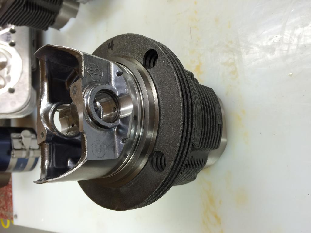
I think I mentioned earlier I set top ring at .020, second ring at .015. Piston to cylinder clearance left at .002.
Installing pistons into jugs...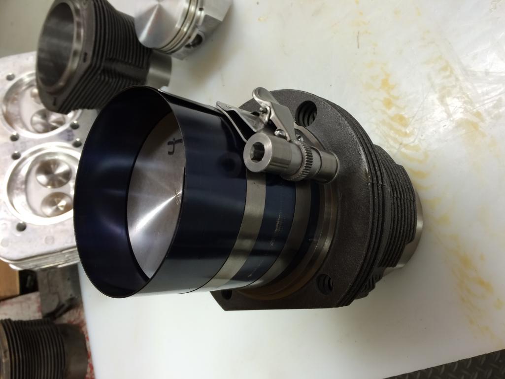
I hate (HATE) these new (to me) spiral-in wrist pin retainers. I hate them I say!
Posted by: sdoolin May 30 2016, 06:58 PM
And finally on side goes together (sort of still). I mangled one of the oil scraper rails so need to make an order before I do the other side. For now this is loosely bolted up with spacers and I will return to it when I get back from a week's worth of travel for work.
I still hate the spiral-in wrist pin retainers. No one can change my mind on that.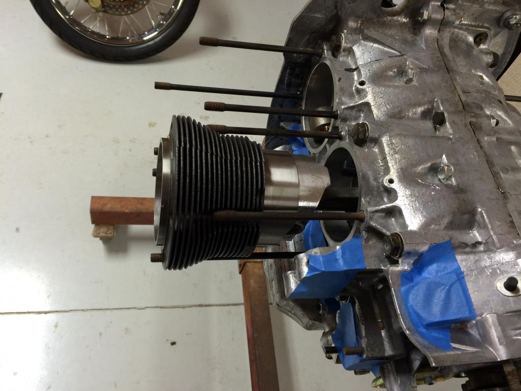
Have I mentioned that I hate the new spiral-in wrist pin retainers?
Posted by: stugray May 31 2016, 06:31 AM
Have I mentioned that I hate the new spiral-in wrist pin retainers?
I saw a youtube vid where the person stretched the springs out so they looked more like a spring than a washer when sitting on the table.
Then they can go in with one finger.
You just start one end then compress the spring and they snap right in.
For getting them out, I took a tiny screwdriver and bent the tip to form a tiny hook to grab the end.
Like this one:
https://www.youtube.com/watch?v=vOYH_WICGYM
Posted by: sdoolin May 31 2016, 11:45 AM
Have I mentioned that I hate the new spiral-in wrist pin retainers?
I saw a youtube vid where the person stretched the springs out so they looked more like a spring than a washer when sitting on the table.
Then they can go in with one finger.
You just start one end then compress the spring and they snap right in.
For getting them out, I took a tiny screwdriver and bent the tip to form a tiny hook to grab the end.
Like this one:
https://www.youtube.com/watch?v=vOYH_WICGYM
Thanks for the linky - I hope it helps me overcome my disdain for the things.
Posted by: Steve Pratel Jun 3 2016, 07:03 PM
This is exactly the way to do it. Stretched them about 3/4 to 1" then twist/rotate it in to place till it is tight and a long pic or thin screwdriver to slowly work it in. I wouldn't call it easy, but it wasn't bad.
Have I mentioned that I hate the new spiral-in wrist pin retainers?
I saw a youtube vid where the person stretched the springs out so they looked more like a spring than a washer when sitting on the table.
Then they can go in with one finger.
You just start one end then compress the spring and they snap right in.
For getting them out, I took a tiny screwdriver and bent the tip to form a tiny hook to grab the end.
Like this one:
https://www.youtube.com/watch?v=vOYH_WICGYM
Posted by: Steve Pratel Jun 4 2016, 10:11 AM
Steve Pratel - I have moved on from the CR thing, have removed .72mm from the tops of the jugs targeting a 9:1 CR.
So I imagine that your earlier measurements/assumptions were off? In an earlier post you said "Plugging bore (96mm), stroke (71mm), deck height (.039) and chamber volume (55.2) into the CB Perf. engine calculator it yields a CR of 9.3 - 1. Is that too much?"
If those number were correct, removing material from the jug will INCREASE your CR not reduce it. If you wanted to go from 9.3 to 9.1 you should have added to the cyl height with a spacer under the jug thus increasing cyl height not reducing. In other words when you reduce height you reduce the chamber size with same bore and stroke, this increases CR. Unless your initial measurements were off or you are doing new math. Either way its your engine man, do what you want.
Posted by: sdoolin Jun 5 2016, 08:05 AM
Steve Pratel - I have moved on from the CR thing, have removed .72mm from the tops of the jugs targeting a 9:1 CR.
So I imagine that your earlier measurements/assumptions were off? In an earlier post you said "Plugging bore (96mm), stroke (71mm), deck height (.039) and chamber volume (55.2) into the CB Perf. engine calculator it yields a CR of 9.3 - 1. Is that too much?"
If those number were correct, removing material from the jug will INCREASE your CR not reduce it. If you wanted to go from 9.3 to 9.1 you should have added to the cyl height with a spacer under the jug thus increasing cyl height not reducing. In other words when you reduce height you reduce the chamber size with same bore and stroke, this increases CR. Unless your initial measurements were off or you are doing new math. Either way its your engine man, do what you want.
Nope, my earlier measurements/assumptions were spot on. There is a 1mm step in the head which essentially adds to the deck height, and I was not including that in my original measurement (my posts actually describe this in great detail - maybe you could read more carefully).
I have now removed .72mm from the top of each jug and have re-measured deck height. Deck height in the jug is .33mm. Add that to the 1mm in the head for a total deck height of 1.33mm. Plug the numbers into the calculator and it returns CR of 9.00:1
Exactly what I was looking for. Not new math and yes - it is my engine and I shall proceed as I see fit. Thanks for your help...
Posted by: MarkV Jun 5 2016, 09:08 AM
Just seems odd that the entire 914 world has to add shims to get their CR set and you are having to build a special jig to remove material from the tops of the cylinders. Did you ask Len about the step in the head? I looked at the photos and can't tell if the step is a recess or if it is proud of the combustion chamber. If it's proud of the head then I guess I can see why you are doing what you are doing. Why do the heads have a step are they some kind of ultra low compression bus heads or something?
Posted by: stugray Jun 5 2016, 09:18 AM
I got sage advice from HAM that there is 1mm of step (deck height) in my cylinder heads. This gives me a total deck height of 2mm.
I am targeting 9:1 Compression ratio. Plugging the numbers into CB's engine calculator and solving for deck height it yields 1.28mm for a CR of 9:1.
If the heads have a 1mm lip, did you account for that in your combustion chamber number?
Or did you measure the comb. chamber volume?
You comb chamber number seems smaller than a stock head.
I had to shave my heads down significantly to get below 55 cc.
Stock is almost exactly 60 cc.
I did account for the 1mm step in the heads in my combustion chamber number, or rather Len did at HAM. I did not CC the heads myself, that was done by Len at HAM. The spec sheet that came with the heads says the chambers are 55.2 CC. I am pretty sure Len's number is accurate. Much more so than mine.
I still find this conclusion suspicious.
I had my heads machined significantly and barely made it to 55 cc without the 1mm step.
If the step is designed to add to deck height, then it is not obvious if the 1mm contributes to combustion chamber volume OR deck height.
I fear that you might be double booking that value in your calculations.
The only way to be sure is to measure them yourself or call Len and ask.
If you measured the comb chamber volume with the clear acrylic disk sitting on top of the 1mm lip vs sitting down flush with the comb chamber, you would get a difference of 2.3 CC
There has to be a simple answer to: "WHY is there a 1mm step in the heads?"
I have never seen or heard of that as that is an automatic deck height of .039 assuming that the pistons are flush with the top of the cylinders.
Maybe that step is for pistons with a non standard wrist pin height?
Posted by: sdoolin Jun 5 2016, 09:24 AM
Just seems odd that the entire 914 world has to add shims to get their CR set and you are having to build a special jig to remove material from the tops of the cylinders. Did you ask Len about the step in the head? I looked at the photos and can't tell if the step is a recess or if it is proud of the combustion chamber. If it's proud of the head then I guess I can see why you are doing what you are doing. Why do the heads have a step are they some kind of ultra low compression bus heads or something?
I agree it seems odd that I am seemingly the only guy on the planet (in the "world") to go down this road.
Len is the individual that informed me of the 1mm "step" in the heads. It is proud of the roof of the combustion chamber proper. I don't know if the heads are anything other than "standard" RS spec heads from HAM.
Len has weighed in on my build a few times by PM, which leads me to believe he is reading this thread occasionally. The fact that he has not weighed in negatively with respect to the removal of material from the jugs leads me to believe I am OK.
I test fit everything yesterday (a few times) and I measured .33mm (1/3 of a turn) of deck height in the jug with my calibrated screw/plate measuring device. The measurement is very repeatable, and is very (very) nearly identical across all cylinders.
The heads bolt up, with a small gap between bottom of head and top fin of the jug (no gasket at base of jug, or in the head). I did not measure this gap (yet) but since there is space there with everything torqued to spec, I believe I am OK.
Posted by: sdoolin Jun 5 2016, 09:32 AM
I got sage advice from HAM that there is 1mm of step (deck height) in my cylinder heads. This gives me a total deck height of 2mm.
I am targeting 9:1 Compression ratio. Plugging the numbers into CB's engine calculator and solving for deck height it yields 1.28mm for a CR of 9:1.
If the heads have a 1mm lip, did you account for that in your combustion chamber number?
Or did you measure the comb. chamber volume?
You comb chamber number seems smaller than a stock head.
I had to shave my heads down significantly to get below 55 cc.
Stock is almost exactly 60 cc.
I did account for the 1mm step in the heads in my combustion chamber number, or rather Len did at HAM. I did not CC the heads myself, that was done by Len at HAM. The spec sheet that came with the heads says the chambers are 55.2 CC. I am pretty sure Len's number is accurate. Much more so than mine.
I still find this conclusion suspicious.
I had my heads machined significantly and barely made it to 55 cc without the 1mm step.
If the step is designed to add to deck height, then it is not obvious if the 1mm contributes to combustion chamber volume OR deck height.
I fear that you might be double booking that value in your calculations.
The only way to be sure is to measure them yourself or call Len and ask.
If you measured the comb chamber volume with the clear acrylic disk sitting on top of the 1mm lip vs sitting down flush with the comb chamber, you would get a difference of 2.3 CC
There has to be a simple answer to: "WHY is there a 1mm step in the heads?"
I have never seen or heard of that as that is an automatic deck height of .039 assuming that the pistons are flush with the top of the cylinders.
Maybe that step is for pistons with a non standard wrist pin height?
The heads are brand new from HAM and the spec sheet that came with them (hand written - probably by Len) indicates that specific combustion chamber volume. I have not CC'd them myself as I (still) trust Len's number much more than I would mine. Len has communicated this 1mm step to my via PM, and he indicated I needed to add it to my overall deck height. I believe his words to me were "you'll have plenty of room". I choose to believe the guy.
I guess we'd need Len to weigh in on the reason for the 1MM step. It is there, I can see it and I even measured it (it is 1mm). I'll try to snap a picture of it today.
Thanks for the thoughts Stugray.
Posted by: sdoolin Jun 5 2016, 10:01 AM
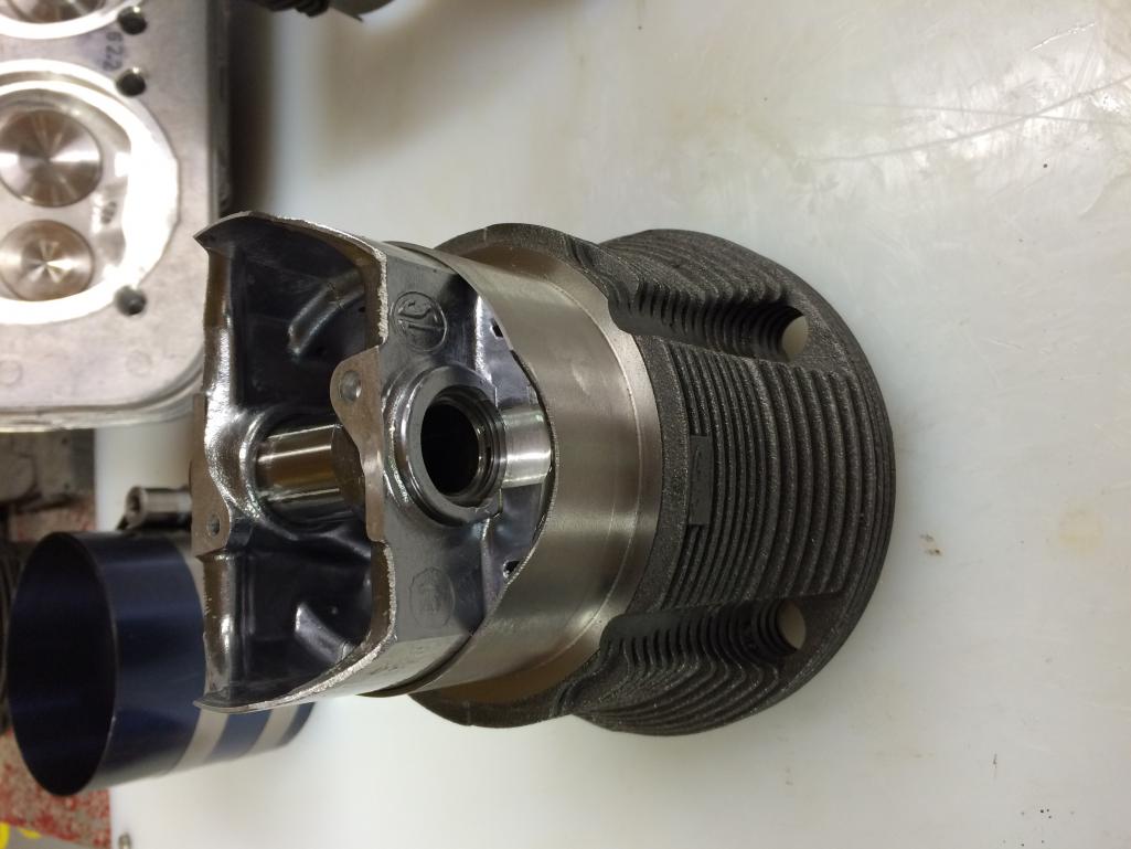
The mysterious 1mm "step" really does exist folks, pic below...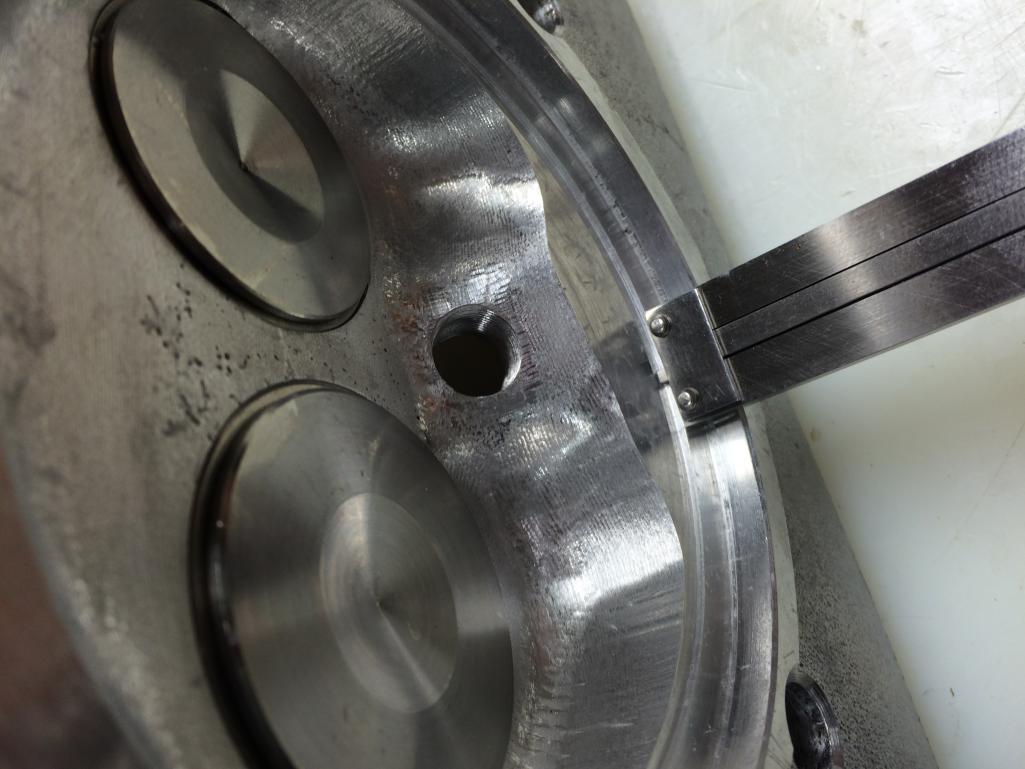
Posted by: sdoolin Jun 5 2016, 10:09 AM
Posted by: sdoolin Jun 5 2016, 10:12 AM
Combustion chamber volume as measured by HAM...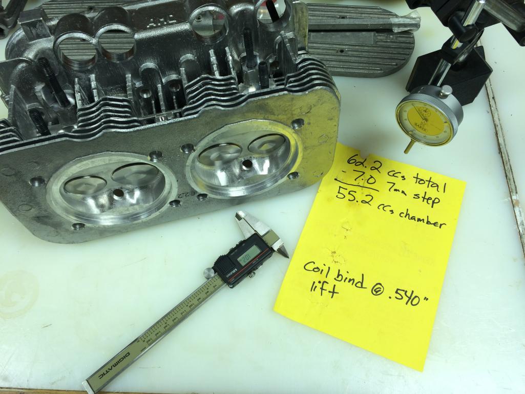
Posted by: MarkV Jun 5 2016, 10:29 AM
You would think that if Len saw this thread he would chime in. There must be some kind of explanation. Hopefully you aren't subtracting for a step that has already been subtracted.
I would probably mock up a pair of lifters, push rods and rockers and do the clay test to verify that you aren't going to have valves getting too close to pistons.
Posted by: sdoolin Jun 5 2016, 10:34 AM
You would think that if Len saw this thread he would chime in. There must be some kind of explanation. Hopefully you aren't subtracting for a step that has already been subtracted.
I would probably mock up a pair of lifters, push rods and rockers and do the clay test to verify that you aren't going to have valves getting too close to pistons.
I have reached out to Len, and yes - I do intend to clay the heads. I will manufacture an adjustable pushrod this week such that I can use the exact ball ends that came with my pushrods.
Posted by: HAM Inc Jun 5 2016, 11:39 AM
The initial reasons we started putting a step in the new heads over 15 years ago was for head strength, and to simulate the thickness of the factory head gasket, which is ~.75mm.
Of course back in the '70's VW issued a bulletin calling for the removal of the head gasket, and restoring the lost deck ht by putting a spacer under the jugs. The 1mm step eliminates the spacer compensation requirement.
Over time we grew the step from .75mm to 1mm for a couple of reasons: it's a safe deck ht spec, and since most (every one I've ever seen, and I've decked over a hundred of them) cases need the spigots decked to correct sagging and warpage the increased step ht allows the cases to be decked to either allow zero deck in the jugs, or to at least compensate for the lost deck ht from a minimal spigot decking, which is generally in the ball park of .005", though bus cases can be quite bad and I've had to deck some of them as much .5mm to correct the sag/warpage.
I have no idea why Steve had so much deck in his jugs, but having decked as many cases as I have I know that these things do vary quite a bit, and I have seen some that were way off from typical factory specs. It happens.
Posted by: MarkV Jun 5 2016, 12:19 PM
The initial reasons we started putting a step in the new heads over 15 years ago was for head strength, and to simulate the thickness of the factory head gasket, which is ~.75mm.
Of course back in the '70's VW issued a bulletin calling for the removal of the head gasket, and restoring the lost deck ht by putting a spacer under the jugs. The 1mm step eliminates the spacer compensation requirement.
Over time we grew the step from .75mm to 1mm for a couple of reasons: it's a safe deck ht spec, and since most (every one I've ever seen, and I've decked over a hundred of them) cases need the spigots decked to correct sagging and warpage the increased step ht allows the cases to be decked to either allow zero deck in the jugs, or to at least compensate for the lost deck ht from a minimal spigot decking, which is generally in the ball park of .005", though bus cases can be quite bad and I've had to deck some of them as much .5mm to correct the sag/warpage.
I have no idea why Steve had so much deck in his jugs, but having decked as many cases as I have I know that these things do vary quite a bit, and I have seen some that were way off from typical factory specs. It happens.
The question is whether he should have used the 62.2 cc figure that you provided or whether he should have subtracted for the step and used 55.2 as his combustion chamber size. I vaguely remember that when you did my heads 9 years ago they came back with a step but I used the cc number that you calculated. It seems like if he subtracts for the step the compression ratio is going to be calculated wrong.
Posted by: DaveO90s4 Jun 5 2016, 05:16 PM
Assume the 62.2 chamber volume is inclusive of the 1.01 mm step (not an unreasonable assumption). Assume also flat top pistons.
Swept volume is 514.12 cc
Chamber vol is 62.2 cc minus 0.72x48x48x pi equals minus 5.2 cc yield chamber vol 57.0 cc
Add stated 0.039" (1 mm) deck height equals 7.2 cc
Total volume at bdc equals 514.12+ 57.0 + 7.2 = 578.32 cc
vol at tdc equals 57.0 + 7.2 = 64.2
Static cr = 578.32 / 64.2 = 9.008.
That's my maths anyway.
Looks spot on. Subject to the initial two assumptions
Dave
Posted by: HAM Inc Jun 5 2016, 05:54 PM
If you read the yellow spec sheet, which we prepare with every pair of our new heads, you'll see the following:
Chamber volume = 55.2cc's
1mm Step volume = 7.0cc's.
Total head related volume = 62.2cc's
Add 62.2cc's to the volume in the jugs @ TDC and you have total unswept volume.
Seems pretty straight forward to me, but if you guys have a suggestion of how to make this any clearer, I'm all ears.
Posted by: stugray Jun 5 2016, 06:25 PM
Dave090s4's calcs are correct.
They match mine:
96mm X 71mm swept volume:
48X48X3.14159 X 71 = 513,914 / 1000 = 513.914cc
Head comb chamber (including 1mm step) = 62.2cc
Volume of step = 48X48X3.14159 X1 = 7.2cc
Comb chamber (minus step) = 62.2 – 7.2 = 55cc
Measured deck height before trim = 1mm
Cyl. Deck height after trimming of .72mm = 1.0 - .72 = .28mm
Deck height = 1mm (in head) + .28mm (in cyl) = 1.28 mm
Deck height volume = 48X48X3.14159 X 1.28 = 9.26 cc
Total volume = Swept volume + deck height volume + comb chamber volume
TV = 513.914 + 9.26 + 55 = 578.174
Compressed volume = deck height volume + comb chamber volume
CV = 64.26
CR = Total Volume / Compressed volume
CR = 578.174 / 64.26 = 8.997
So I think the answer is: this works just fine.
However if the OP had ordered the heads without the 1mm step, he could have shimmed the cyls UP to reach target CR instead of machining the cyls DOWN.
That is exactly how mine is setup, but I had heads with 56cc comb vol (no step), cyls shimmed for a total deck of .89mm for a final CR of 9.2.
My spigots HAD been decked so my cyl only deck was less than 1mm to start with.
If I had wanted to adjust down to CR = 9.0, I would only have had to add more shims.
Posted by: sdoolin Jun 5 2016, 06:55 PM
Y'all are killing me. I think we are in violent agreement that my CR is very nearly 9.0:1?

Posted by: DaveO90s4 Jun 5 2016, 07:31 PM
Seems that way!!
Maybe revised spec wording along the lines "Total combustion chamber volume per chamber is 62.2 cc. This volume is measured from the cylinder head compression mating surface so includes the volume created by the 1.00 mm lip."
Just a suggestion.
DaveO
Posted by: stugray Jun 5 2016, 08:47 PM
I even agreed a while back that it seemed right
At least all of my confusion/interest has been due to the trimming of the cylinders and the existence of that lip.
Sdoolin's method will work out fine, its just somewhat non-standard (unorthodox? :-).
Almost, but not quite, entirely Un-like tea?
It's all the same until he needs a replacement cylinder .... or head.
Posted by: sdoolin Jun 6 2016, 05:32 PM
Waiting for some more parts to come in and waiting for my buddie's lathe to become available to manufacture an adjustable pushrod. Can't bring myself to bolt the heads on until I have the adj. pushrod in hand - they are just to pretty...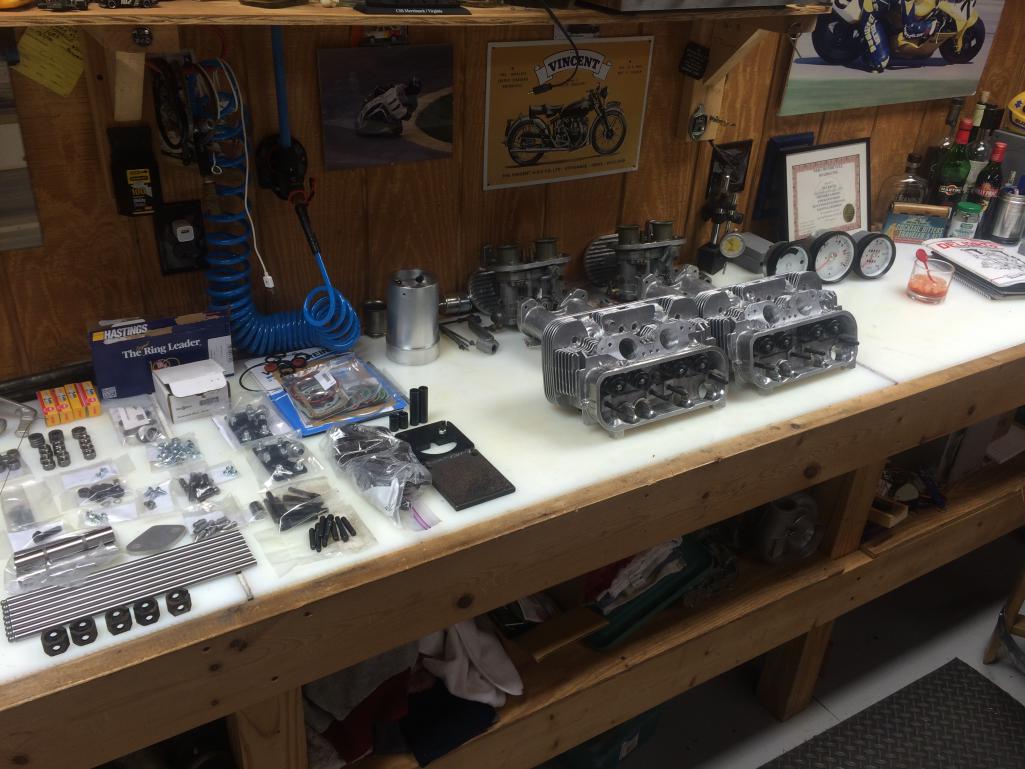
So many parts still to go...
Dual Dells need to be completely gone through (and I purchased a second set) - I am comfortable rebuilding them - done it plenty with my old bus. Still need to find a dizzy and all engine tin and fan housing still being prepped for paint and/or powder coat.
I munged up (slightly) one exhaust manifold stud whilst installing into head. Really (really) pisses me off.
Posted by: Steve Pratel Jun 6 2016, 11:13 PM
Y'all are killing me. I think we are in violent agreement that my CR is very nearly 9.0:1?
LOL, I feel your pain......... I am little better than an assembly monkey, and all the fancy pants math makes me head hurt....
You can check your attitude.... My only weighing in was my concern over the issue of how reducing deck height would increase your CR, but I'm just an Army grunt.... Looking at my HAM remanufactured heads (as in the original heads being remanufactured) I dont see the step.
In my 2056 build I used the HAM Remanufactured Stock Heads, Stock Crank, Stock Con Rods, 96mm Keith Black Pistons and EMW Jugs with a .060 spacer to get an 8.6 +/- CR. Why did I use a .060 spacer? Jorge at EMW recommended it
 No science involved. My goal was to stay as stock as possible and when I set up the pushrods, came out with measurements within .001 to stock pushrods, so I am guessing my deck height at least as it relates to valve train was pretty close to stock.
 I'd hate to see you with a super high CR or to have unauthorized valve/position contact.....
This has been a great learning experience.
Attached thumbnail(s)
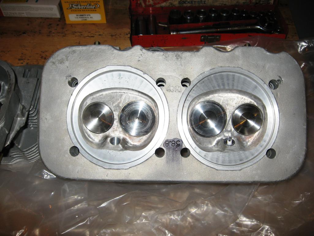
Posted by: stugray Jun 7 2016, 06:43 AM
I'd hate to see you with a super high CR or to have unauthorized valve/position contact.....
I have:
~9.2 CR
heads that were cut to give me a 56cc comb chamber
.035 Deck Height
~.500 Valve lift with stock valve sizes
And I have sufficient room to avoid valves hitting pistons.
he should be fine, but the clay test is in his plans to be sure.
Posted by: sdoolin Jun 8 2016, 08:23 AM
Completed machine work on 1.7 rockers last night. Set the lathe up with a single rocker shaft and its mounts so that I could more or leass assembly line this procedure. Take material off, remove rocker, leave shaft in the "erector set jig", slide another rocker on shaft, repeat.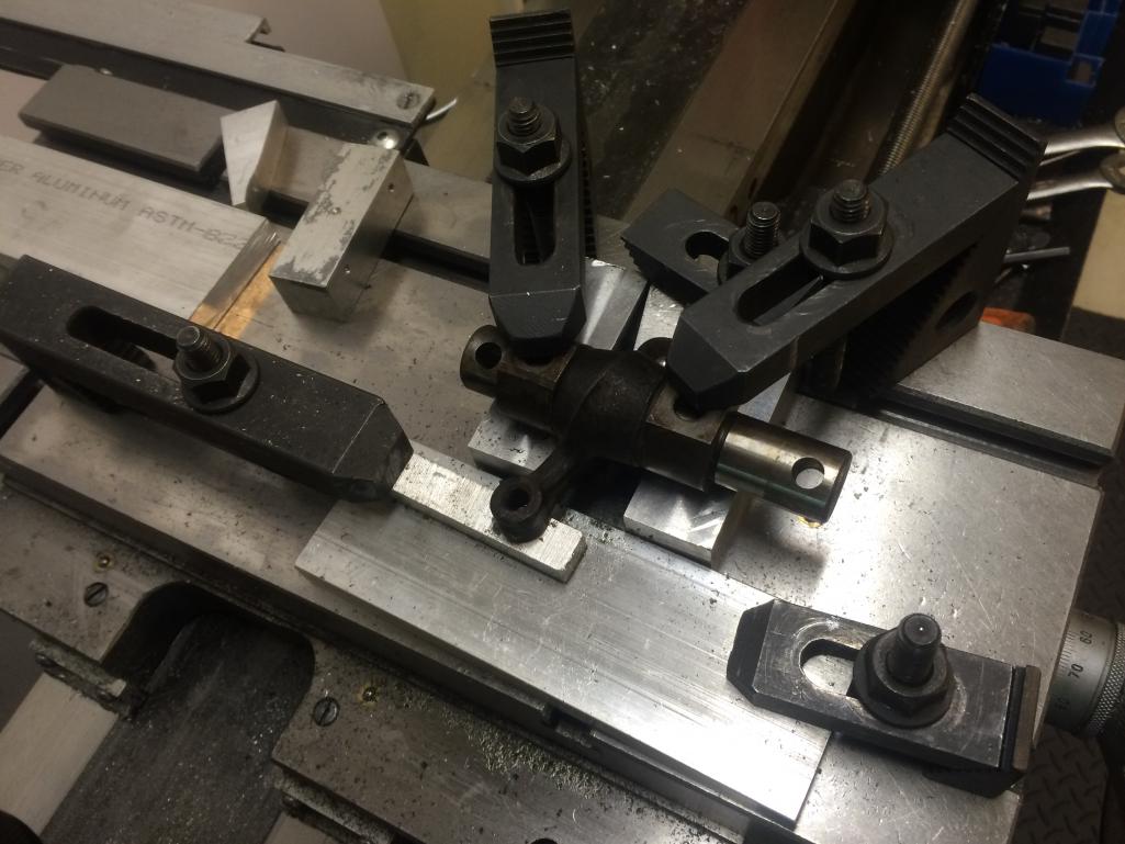
Now - strangely I seem to have misplaced a single rocker shaft mount. This stuff has been bouncing around my garage and barn for like 20 years. So now on a search for a single item in order to bolt up the rockers...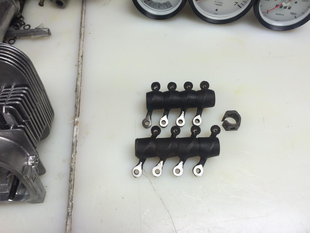
Posted by: stugray Jun 8 2016, 08:50 AM
with all of the jigs and measuring capability you have, is there any way for you to measure the rocker ratio?
Posted by: sdoolin Jun 8 2016, 08:57 AM
with all of the jigs and measuring capability you have, is there any way for you to measure the rocker ratio?
Good question, I'm not sure how to approach that? Amount of movement on the pushrod side of the rocker vs amount of movement on the valve side?
Posted by: sdoolin Jun 8 2016, 11:22 AM
Not to highjack my own thread - but shouldn't rocker arm ratio for these rockers be known (I haven't googled it yet)? They are like 40 years old (probably older) and I'd think the spec would be published somewhere.
While I had not intended to measure this - in fact it never crossed my mind (ever), now I continue to mull it over... 
Posted by: sdoolin Jun 12 2016, 06:55 PM
Adjustable pushrod finally complete. It isn't pretty, but I believe it will work. Used a scrap piece of chromoly tubing with same OD as pushrods from T IV Store (Manton), squared up the ends on the lathe, welded in a nut on one side and a bolt on the other and off we go. Happily the ball ends are the _exact_ same ones that will go in the finished engine and my reading indicates that to be important.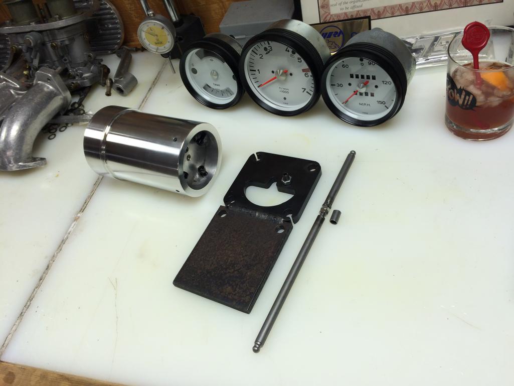
So in the picture we have all of the stuff I had to fabricate for this build (so far). The adjustable pushrod, the deck height measuring apparatus, and the much maligned fixture to deck the jugs. I put a high polish on the jug fixture since I am the only guy in the world to ever have to go down this road and I figure it'll never get used again. But - it will live proudly on a shelf in my shop.
Don't tell my lovely wife about the white faced gauges please...
Posted by: Steve Pratel Jun 12 2016, 07:07 PM
Adjustable pushrod finally complete. It isn't pretty, but I believe it will work. Used a scrap piece of chromoly tubing with same OD as pushrods from T IV Store (Manton), squared up the ends on the lathe, welded in a nut on one side and a bolt on the other and off we go. Happily the ball ends are the _exact_ same ones that will go in the finished engine and my reading indicates that to be important.
So in the picture we have all of the stuff I had to fabricate for this build (so far). The adjustable pushrod, the deck height measuring apparatus, and the much maligned fixture to deck the heads. I put a high polish on the jug fixture since I am the only guy in the world to ever have to go down this road and I figure it'll never get used again. But - it will live proudly on a shelf in my shop.
Don't tell my lovely wife about the white faced gauges please...
What gauges? I'm eying that Whiskey Sour........ Or in my case Irish Mist/Drambuie & Lemon
Great looking shop and machining capability you have. Looking forward to seeing your project come together.
Posted by: sdoolin Jun 16 2016, 08:13 AM
As the younger crowd says these days - "epic fail". 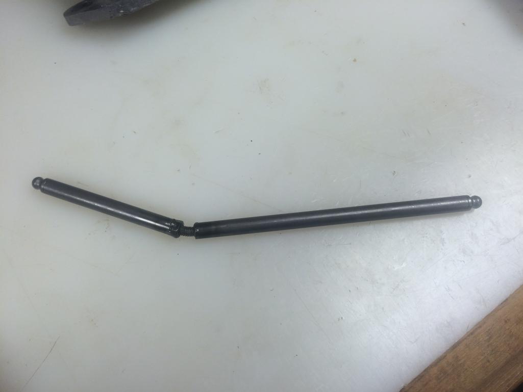
Maybe I need less valve spring for this operation?
I really (really) wish Type IV Store would sell me their re-engineered adjustable pushrod (from Manton) that uses the exact same ball ends that they supply with their pushrods (again from Manton). This item is "with Jake's engine builder" for evaluation currently. Hopefully he will bless it (soon) and I can move on...
Posted by: 2mAn Jun 16 2016, 04:10 PM
I cant help with your calculations but I can say Im quite amused with your attention to detail. Shold be a fun runner when you finish
Posted by: Java2570 Jun 16 2016, 05:01 PM
As the younger crowd says these days - "epic fail".
Maybe I need less valve spring for this operation?
I really (really) wish Type IV Store would sell me their re-engineered adjustable pushrod (from Manton) that uses the exact same ball ends that they supply with their pushrods (again from Manton). This item is "with Jake's engine builder" for evaluation currently. Hopefully he will bless it (soon) and I can move on...
I'm thinking I remember Len Hoffman saying that you should use the lighter valve springs to do the valve geometry measurements.....if your heads have the double springs. Since my RS+ heads just had the single spring, I didn't worry about it.
Perhaps Len will chime in here, or someone else with more knowledge than I!
Posted by: porschetub Jun 18 2016, 12:36 AM
I cant help with your calculations but I can say Im quite amused with your attention to detail. Shold be a fun runner when you finish
Been following this one and what the OP is doing is a full blueprint motor,reason that Jake and others charge what they do,all about going past basic specs and doing it right,differance between average and top spec.
Posted by: stugray Jun 18 2016, 08:39 AM
For my first iteration of checking my valve geometry I used some "surrogate" springs that I found at Ace that fit, but had far less strength than even my single spring setup.
If you cant solve your problem with the adjustable pushrod, I might consider loaning you mine.
Posted by: McMark Jun 18 2016, 09:28 AM
I use full valve spring pressure. But I tapped the pushrod tube directly, so I'm using a thicker stud in between the rod halves.
Posted by: sdoolin Jul 4 2016, 06:04 AM
Since the adjustable pushrod a manufactured was a failure, I thought I'd order one from Manton. Seemed easy enough, but you can see that what they sent me is not useful for a type IV build. This is becoming infuriating. I'll try aircooled.net next...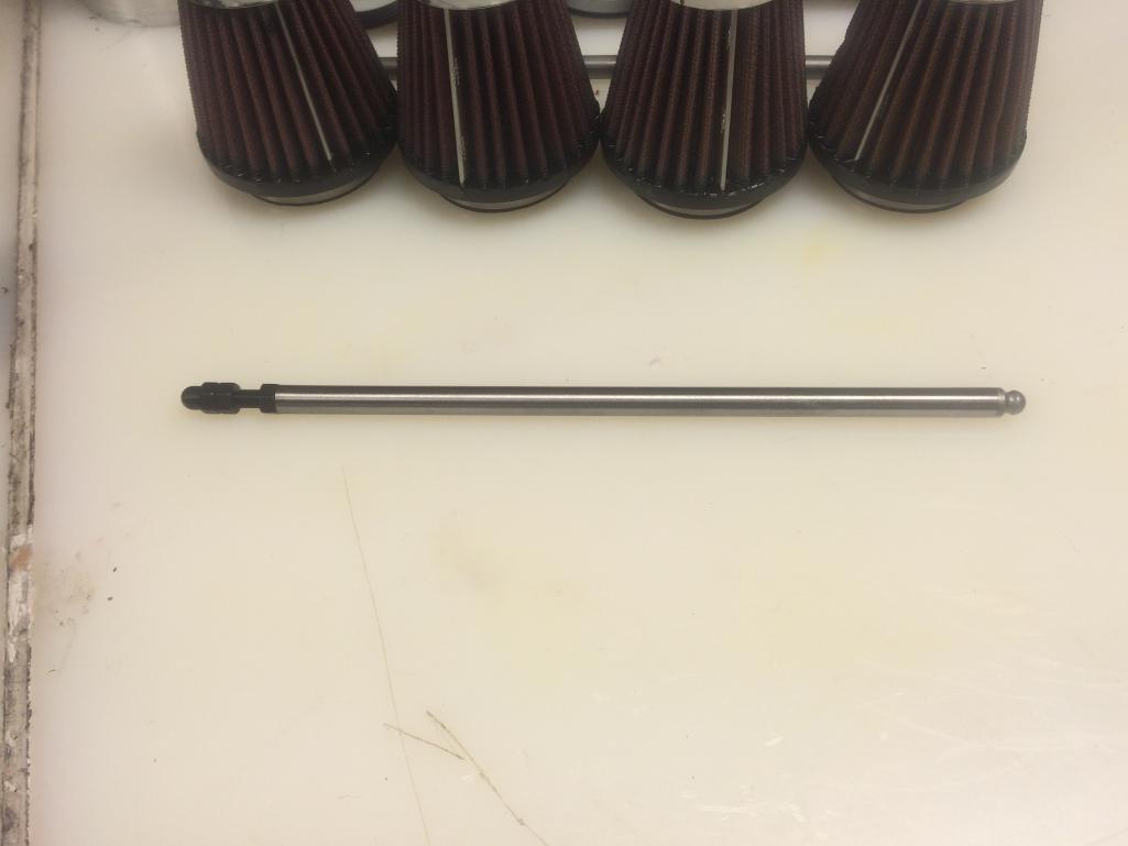
Posted by: sdoolin Jul 5 2016, 03:46 PM
OK so I couldn't take it any longer and I thought I'd give this Manton adj. pushrod a shot. Can't really use the locking nut on it due to its location, but I think I got it to work. Pics of my setup, (and as is the norm now my pics are rotated by 914world to ensure confusion of reader)...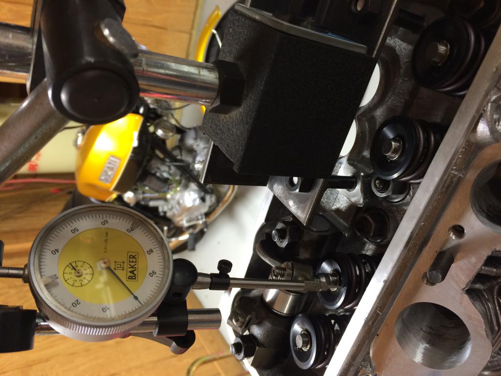
I used a piece of angle and drilled it to fit the rocker shaft studs. It is mounted very securely and the dial indicator is affixed to that. I ensured that the dial indicator returns to zero (the same zero) after turning the engine and even just from jiggling the engine stand. It is quite solid.
Some math (I'm not a math teacher but I did go to engineering school - but please feel free to double check my numbers if you are hugely bored):
Advertised cam lift = .435"
5% of advertised lift (.435 *.05) = .0218" (rounded to .022 below)
Max measured lift can be .435+.022 = .457"
Min measured lift can be .435-.022 = .413"
I managed to get a measured lift of 11.55mm = .454" after just a few adjustments to the pushrod. That number is very repeatable and is just under max measured lift value from above. So it seems I got this right?
This is all on the intake valve on #1.
With that measured lift, and with one spacer under the rocker shaft mounts (not measured yet), I get the following geometry at half measured lift (again pic rotated by 914world for some inane reason):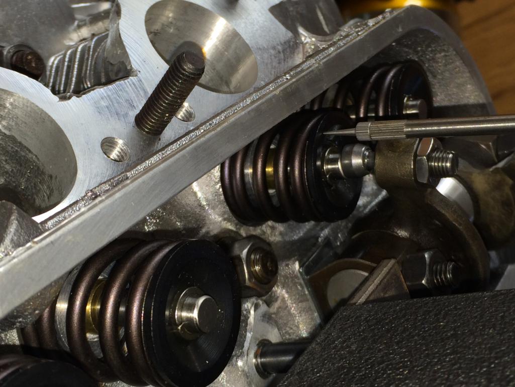
That geometry looks pretty good to me. I think I could get the adjuster only slightly better lined up with the valve, but I would lose some lift. A very - very small amount of lift.
Wondering if I should do this measurement and setup for all valves individually? Would love someone that has actually been down this road to chime in if possible.
Posted by: The Cabinetmaker Jul 5 2016, 04:16 PM
I checked each one so I could measure for each rod and cut them to exact length individually.
Posted by: sdoolin Jul 5 2016, 04:19 PM
I checked each one so I could measure for each rod and cut them to exact length individually.
I think I am going to do the same.
Posted by: stugray Jul 5 2016, 07:04 PM
I checked each one so I could measure for each rod and cut them to exact length individually.
I measured them all and found the average and cut them all to that length.
I didnt want to have to keep rods with certain valves.
And regarding the rocker ratio: If you know the cam lobe lift and now measure the valve lift, you can calculate the ratio.
If you felt like measuring it now, measure how much vertical motion you have on the pushrod with a second dial indicator while measuring the valve lift:
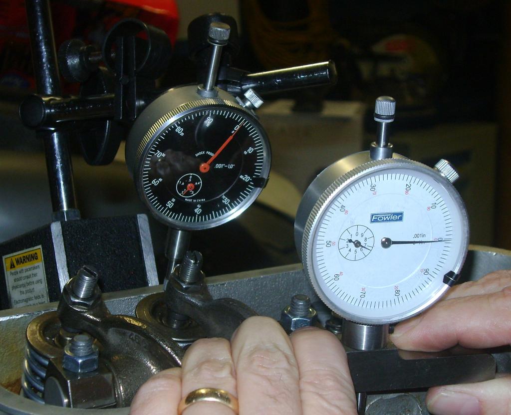
I used a tiny clamp on the pushrod
When I did this the first time I was given the lift at the cam and had to determine that the valve lift was within the 5% of predicted, but then you need to know the rocker ratio to at least two decimal places....
Posted by: sdoolin Jul 7 2016, 10:43 AM
So while I am waiting on my 12" Vernier Calipers to arrive (so's I can accurately measure for pushrod length) I decided to go all creative on the oil fill tube block off plate with some custom engraving...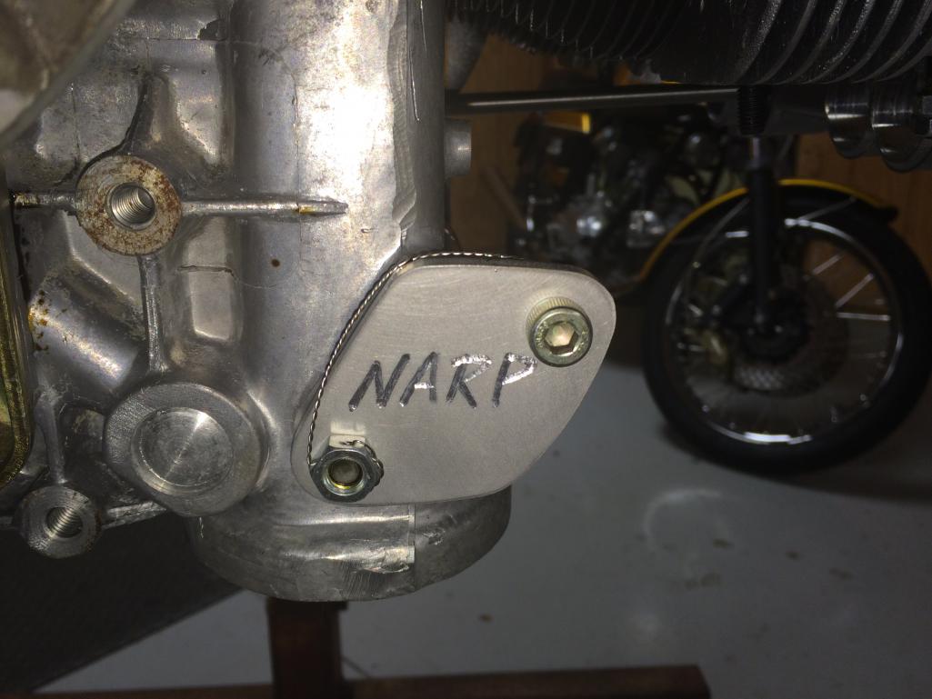
This engine is officially "one of one".
Posted by: sdoolin Jul 10 2016, 08:11 AM
I've gone over the top again. I didn't like the way the swivel foot adjusters were lining up on the valve stems. First pic shows how the #1 intake swivel foot is not even covering the entire valve stem...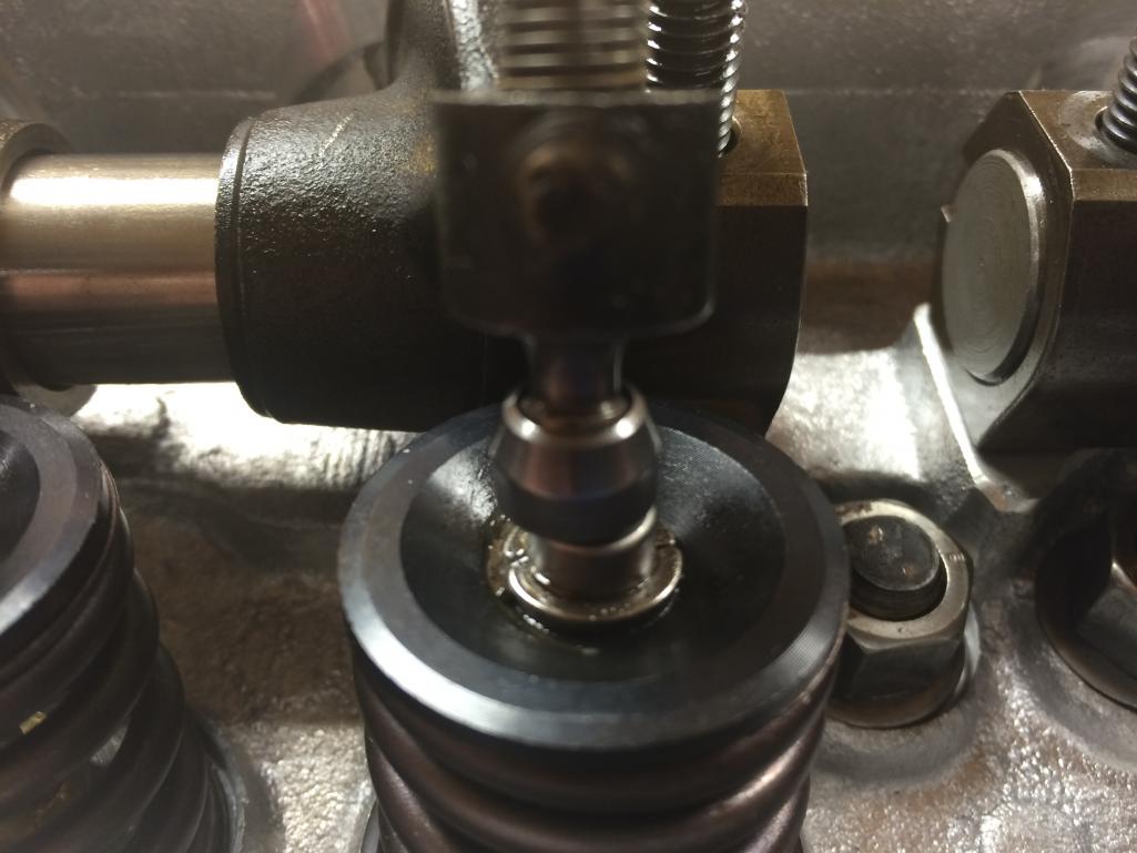
Pretty much all of the valves were like this, with the intakes being farther "off" than the exhausts. Back to the lathe to make each of the rocker shaft clamps slightly oval allowing them to move the rocker(s) over on the shaft...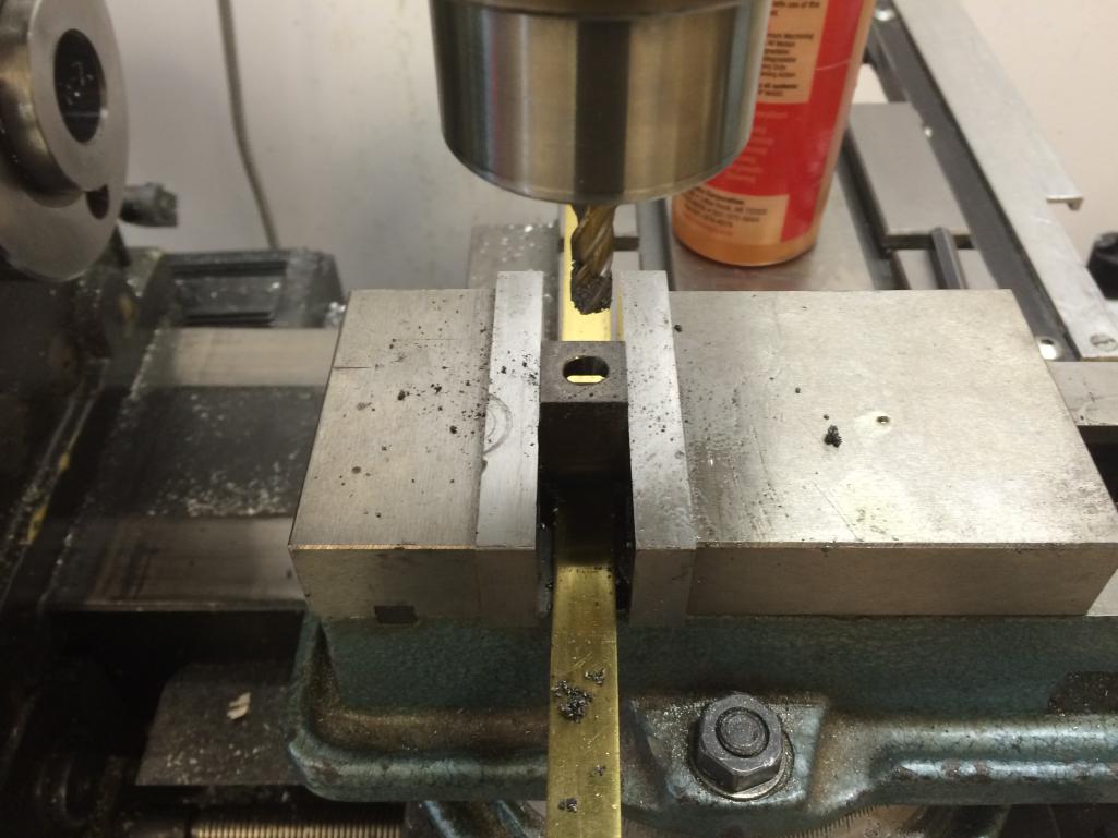
Each clamp was cut in the neighborhood of .5mm, one set was cut .75mm. This got the swivel foot adjusters nicely aligned with the valve stems (picture in next post). Note they are still slightly off center which may allow for the swivel foot to spin the valve, but I'm not sure that spinning the valve even happens with the swivel foot adjusters?
Posted by: sdoolin Jul 10 2016, 08:13 AM
After the clamps were "ovaled"...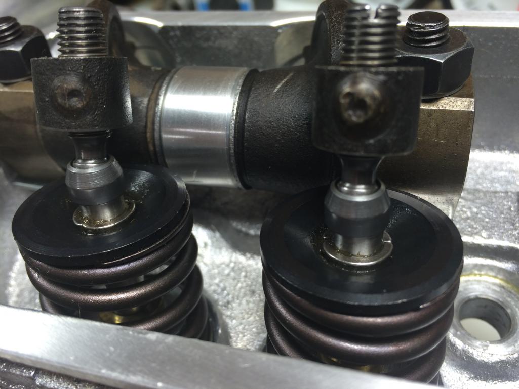
Posted by: Montreal914 Jul 10 2016, 11:39 AM
Isn't that mis alignment there so that the valve is actually rotated over time as it is being opened?
Posted by: sdoolin Jul 11 2016, 12:59 PM
Isn't that mis alignment there so that the valve is actually rotated over time as it is being opened?
Yes I believe that is the reason for the "mis-alignment", and why I left them somewhat mis-aligned. Though I don't see how the swivel foot adjuster is going to be successful rotating the valve. Maybe it does, I just don't know...
Posted by: jcd914 Jul 11 2016, 05:32 PM
Isn't that mis alignment there so that the valve is actually rotated over time as it is being opened?
Yes I believe that is the reason for the "mis-alignment", and why I left them somewhat mis-aligned. Though I don't see how the swivel foot adjuster is going to be successful rotating the valve. Maybe it does, I just don't know...
Yes the off set of the rocker is by design not a manufacturing error.
The rocker pushing off center causes the valve to rotate slightly each time it is opened, this helps keep the valve and valve seat clean.
Jim
Posted by: sdoolin Jul 28 2016, 06:41 AM
Life has gotten in the way of this project for a few weeks, traveling for work and all. I believe I have finally arrived at a happy place with respect to pushrod length.
Cyl IN Lift EX Lift
1 0.449 0.427
2 0.451 0.426
3 0.452 0.416
4 0.450 0.423
Note 1: All with thickest rocker shaft spacer
Note 2: All with 10.754" pushrod
All of those lift numbers are within the +- 5% range suggested by Raby. Also all adjusters nicely aligned with the valve stem at half of measured lift. I still plan to measure valve - piston clearance before final assembly.
It does seem like the swivel foot adjusters may contact the valve covers, I still need to measure that.
Posted by: sdoolin Aug 8 2016, 11:29 AM
Clayed the heads this weekend to ensure no piston/cylinder contact. Looks like I will be fine. Measures right around 2mm...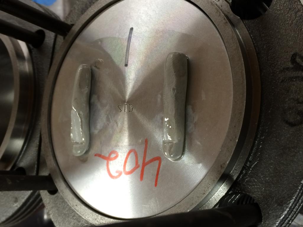
Posted by: Dave_Darling Aug 8 2016, 12:33 PM
How about with the valves opening? Or am I jumping ahead too far?
--DD
Posted by: sdoolin Aug 8 2016, 12:39 PM
How about with the valves opening? Or am I jumping ahead too far?
--DD
That _is_ with the valves opening. You can see indentations from the valves in each of the clay strips. Why would one clay the heads except with valves operating?
Posted by: stugray Aug 8 2016, 12:55 PM
Did you measure cam lobe lift before you installed the cam?
Just curious.
And the valve clearance seems a little close @ 2mm.
That is ~.080.
I seem to recall someone telling me they liked no less than .120, but I would have to check my notes, so don't quote me yet.
And my final length on pushrods was 269.5mm (10.61 in.)
Posted by: draganc Aug 12 2016, 06:54 PM
sorry for the OT request: can you post a pic of your Ducati frontend setup. i'm curious what you did to the caliper mount(s). I tried to zoom into the pics but it's either covered or blurry.
Posted by: barefoot Aug 13 2016, 05:58 AM
Did you measure cam lobe lift before you installed the cam?
Just curious.
And the valve clearance seems a little close @ 2mm.
That is ~.080.
I seem to recall someone telling me they liked no less than .120, but I would have to check my notes, so don't quote me yet.
And my final length on pushrods was 269.5mm (10.61 in.)
Just got my WebCam #494 and measured lobe lift at .345".
WEB card says valve lift is .465" so they assume a rocker ratio of 1.347
Posted by: HAM Inc Aug 13 2016, 06:28 AM
In most of my experiences degreeing T4 cams and setting geometry the intake ratio came in around 1.33 and the exhaust around 1.29.
For years most cam manufacturer used a factor of 1.3 for intake and exhaust.
When we prep heads we set valve spring coil bind limits for any given cam based on my findings.
Posted by: stugray Aug 13 2016, 01:08 PM
In most of my experiences degreeing T4 cams and setting geometry the intake ratio came in around 1.33 and the exhaust around 1.29.
For years most cam manufacturer used a factor of 1.3 for intake and exhaust.
When we prep heads we set valve spring coil bind limits for any given cam based on my findings.
Thank you!
You might recall my thread about rocker ratios.
I got my ass chewed by people telling me "Just use 1.3 like everyone else!"

They must not understand that to get within the 5% valve lift that Jake advertises that you MUST achieve (that is 0.05) you need more than TWO significant figures!
So there is a big difference between 1.29 & 1.33 when trying to calculate valve lift to THREE significant figures.
And my webcam 86b has an advertised valve lift of 0.500/0.500
I measured the cam lobe lift before installation and got 0.365/0.365
So for them to make a cam with 0.365 lobe lift and advertise 0.500 valve lift (.500/.365 = 1.37) they used 1.37 for their rocker ratio.
I installed the cam and measured .504/.475 so the rocker ratio in my engine is closer to 1.38 I/1.30 E.
Posted by: sdoolin Aug 15 2016, 07:21 PM
sorry for the OT request: can you post a pic of your Ducati frontend setup. i'm curious what you did to the caliper mount(s). I tried to zoom into the pics but it's either covered or blurry.
Happy to post Duc pics. I made the Brembo mounts such that I could go back to the APs if ever needed, keeps value in the bike. The forks were not modified at all. I think they are kinda fugly, but they sure do work. Note that the pads don't sweep the entire rotor so there is some rust that develops on the inside "ring" of the rotor. Scotchbrite was invented to fix that. Pic...
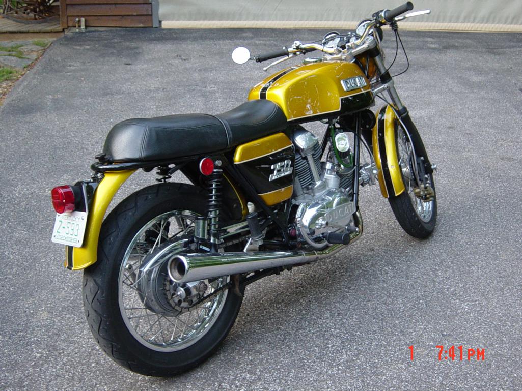
Posted by: sdoolin Aug 15 2016, 07:31 PM
Powder coating finally done. I think it all turned out pretty nicely. Still gonna be awhile till it runs. I still need a dizzy, going to ceramic coat the header/muffler (Bursch), and the dual Dells need to have the CB update kits installed along with complete rebuild.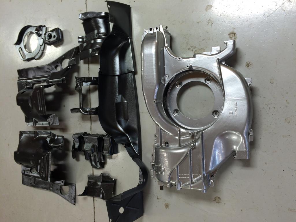
Posted by: RoadGlue Aug 15 2016, 07:32 PM
Dear God, that's one awesome bike!

Posted by: sdoolin Aug 15 2016, 07:36 PM
More PC pics...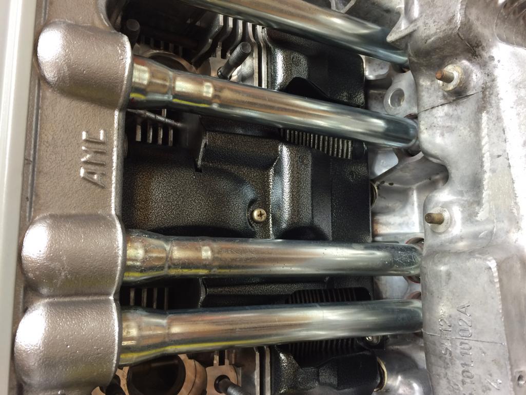
Posted by: sdoolin Aug 15 2016, 07:38 PM
Dear God, that's one awesome bike!
She is a beauty, thanks. And good lord you should hear it run with the Conti pipes.
Posted by: RoadGlue Aug 15 2016, 07:45 PM
She is a beauty, thanks. And good lord you should hear it run with the Conti pipes.
There's your punishment for subjecting my eyes to that eyesore. Please (please) post a video of it running (please).
My Triumph 955i Daytona has the factory carbon high pipe and factory race tune, which sounds great. But in terms of class, it doesn't come close to your old Duc.
Posted by: echocanyons Aug 15 2016, 07:52 PM
Coating looks good. Did you disassemble the two halves of the shroud or have it coated as one piece?
Posted by: sdoolin Aug 16 2016, 04:36 AM
Fan shroud was completely disassembled, cleaned and blasted, then reassembled for powder coat. It was coated all as a single piece with sacrificial hardware (screws) holding it together. It'll get disassembled again, all threaded holes will be chased with a tap, and then stainless allen heads will be used for final assembly. The stainless hardware is not stock, but this aint no concourse build...
Posted by: draganc Aug 20 2016, 09:16 PM
Dear God, that's one awesome bike!
She is a beauty, thanks. And good lord you should hear it run with the Conti pipes.
Yes she is and thank you for the pics! I have been on Ducs for +20 years but never on a bevel. Building and riding custom bikes keeps me unfortunately from finishing my teener.

And now back on track with your awesome build!
Posted by: billh1963 Aug 21 2016, 05:10 AM
Powder coating finally done. I think it all turned out pretty nicely. Still gonna be awhile till it runs. I still need a dizzy, going to ceramic coat the header/muffler (Bursch), and the dual Dells need to have the CB update kits installed along with complete rebuild.
Are you missing some tin?
Posted by: sdoolin Aug 21 2016, 03:36 PM
Powder coating finally done. I think it all turned out pretty nicely. Still gonna be awhile till it runs. I still need a dizzy, going to ceramic coat the header/muffler (Bursch), and the dual Dells need to have the CB update kits installed along with complete rebuild.
Are you missing some tin?
Don't believe so. I just did a complete mock-install with it all today, and all is accounted for. The rear plate is not in the picture but I have it. Now if I could just find all of the rubber bits I need (Alt cooling elbow and a half dozen grommets for wiring harness(es)...
Posted by: billh1963 Aug 21 2016, 03:39 PM
Powder coating finally done. I think it all turned out pretty nicely. Still gonna be awhile till it runs. I still need a dizzy, going to ceramic coat the header/muffler (Bursch), and the dual Dells need to have the CB update kits installed along with complete rebuild.
Are you missing some tin?
Don't believe so. I just did a complete mock-install with it all today, and all is accounted for. The rear plate is not in the picture but I have it. Now if I could just find all of the rubber bits I need (Alt cooling elbow and a half dozen grommets for wiring harness(es)...
Looked like you were missing one of the under cylinder head pieces. Maybe I just didn't see it.
Posted by: sdoolin Aug 21 2016, 03:42 PM
Powder coating finally done. I think it all turned out pretty nicely. Still gonna be awhile till it runs. I still need a dizzy, going to ceramic coat the header/muffler (Bursch), and the dual Dells need to have the CB update kits installed along with complete rebuild.
Are you missing some tin?
Don't believe so. I just did a complete mock-install with it all today, and all is accounted for. The rear plate is not in the picture but I have it. Now if I could just find all of the rubber bits I need (Alt cooling elbow and a half dozen grommets for wiring harness(es)...
Looked like you were missing one of the under cylinder head pieces. Maybe I just didn't see it.
I have them both, they are sandwiched together in the pic. Good eyes...
Posted by: sdoolin Aug 21 2016, 09:20 PM
Lots of work completed today. Fan shroud assembled, all engine tins test fit. I am really happy with the powder coat on the tins. Using anti-seize on everything. I think I spent more then an hour on the oil dipstick tube, recall these cases are from a bus I used to own so the oil dipstick needed to be relocated.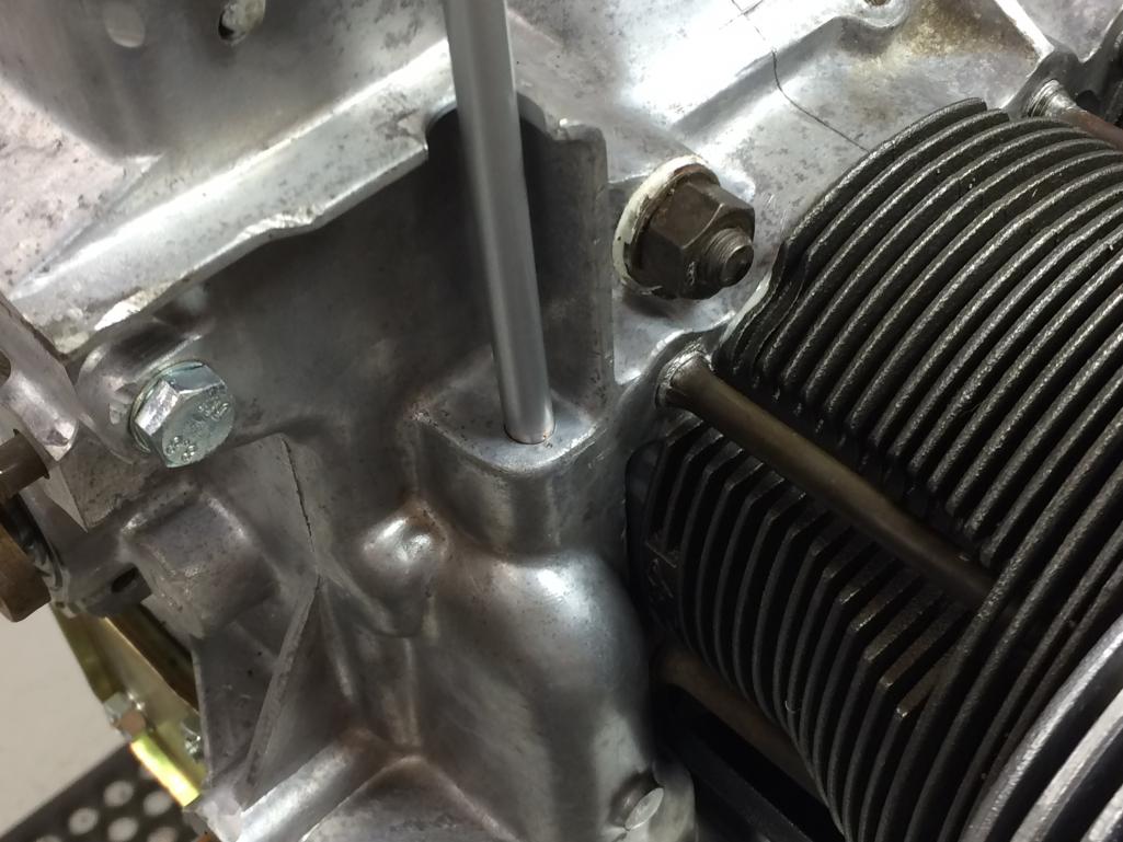
Peened the case and the tube in the neighborhood of where they come together...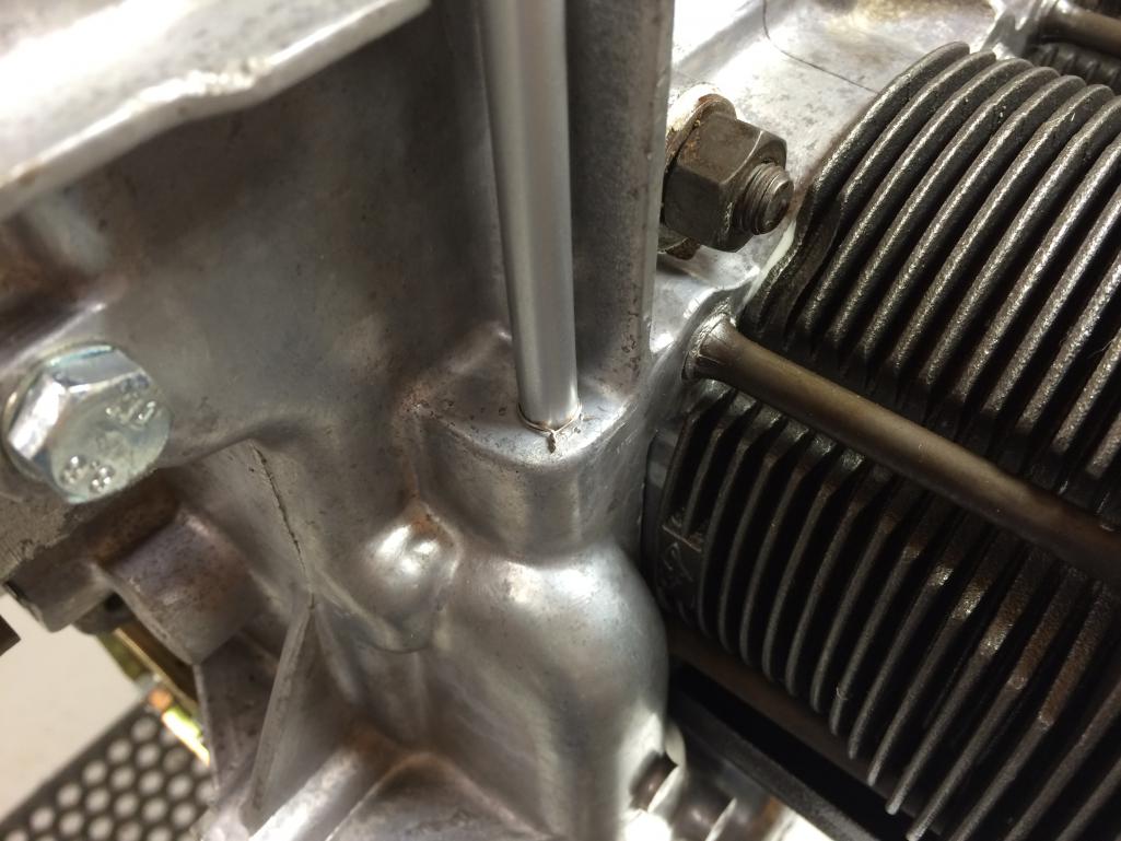
Slotted the tube and safety wired it to limit movement (I love safety wire).
Then (next post), used some JB weld to give it some glue.
Posted by: sdoolin Aug 21 2016, 09:25 PM
And here's the final solution. Kind of crude side of the shop but I have had these cases since my college days (a very long time ago) so keeping them going in this 914 is just cool. Plus, no one can see this crude solution unless they follow this thread. No concourse here..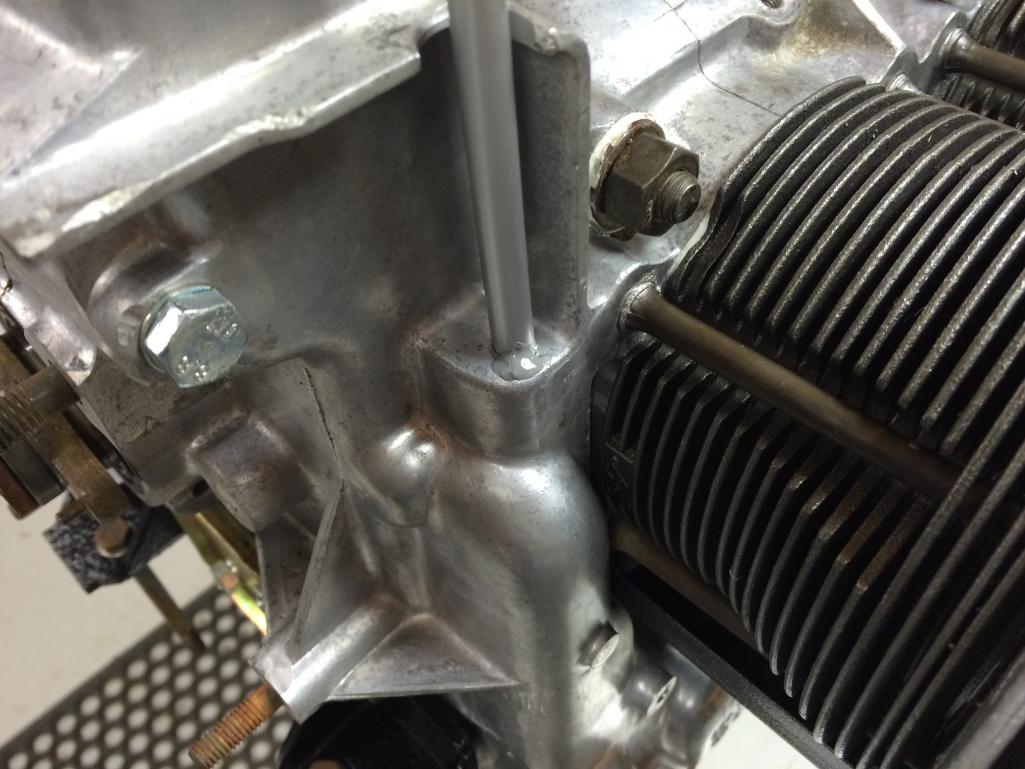
Posted by: sdoolin Aug 21 2016, 09:30 PM
More pics because I am bored and this thing is coming together nicely...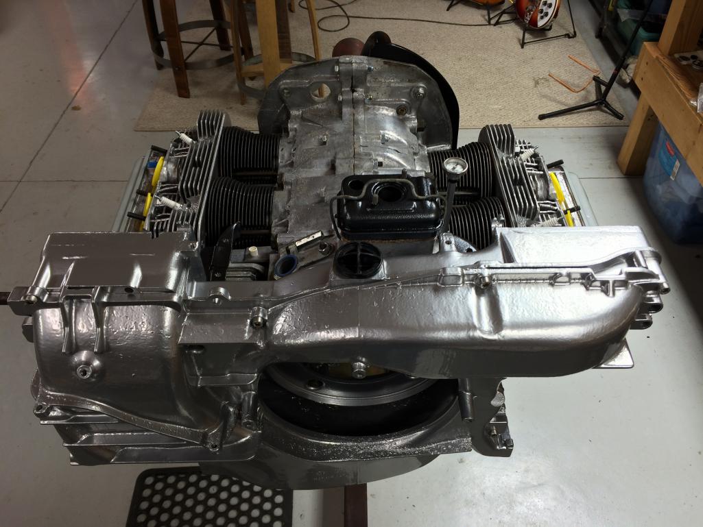
Posted by: sdoolin Aug 21 2016, 09:34 PM
And another...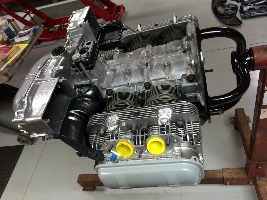
Posted by: sdoolin Aug 21 2016, 09:40 PM
One more before I go finish a bottle of Old Forrester.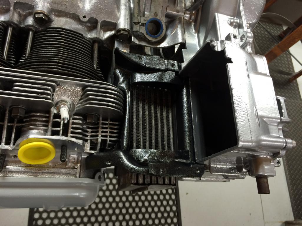
I won't get much more done this month because dag gone it I have tickets to the Italian F1 GP at Monza in a week and a half. That will take some time for sure.
Right now I hope this thing runs either late (late) fall, or maybe not till next spring. No reason to rush...
Posted by: sdoolin Aug 22 2016, 11:49 AM
Cooling flaps going back in. It doesn't seem to me like the flap on the left (cyls 1 & 2) opens far enough? At full open (travel limited by other flap bottoming on oil cooler vent/tin), it still seems kinda closed to me...
Pic below is full open (thanks 914world for rotating my pics)...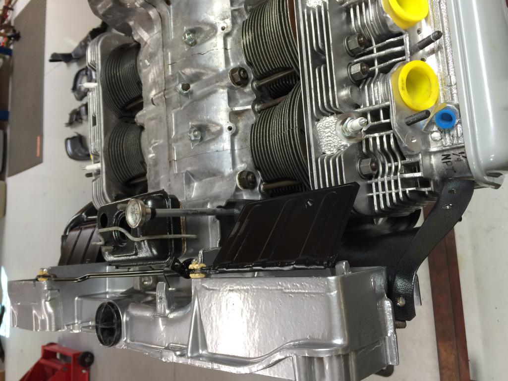
Posted by: draganc Aug 22 2016, 09:00 PM
And another...
Finally something to complain about - your engine stand is filthy!
aren't you ashamed to but that thing on your super clean floor?

Posted by: sdoolin Aug 23 2016, 06:54 AM
Engine stand is filthy - yes. Good eyes. It bugs me continuously. I very nearly had it powder coated before I began this build, but the build was ready before I pulled the trigger.
It will get powder coated before my next build (the engine that came out of the car (dropped #3 exhaust valve) will get built to a ~2.3L). Then when that build is complete this engine will become permanent barn art with a special stand and a glass top (for Bourbon drinks).
Posted by: sdoolin Aug 26 2016, 01:40 PM
Engine tins all installed -just as a mock-up. It'll all come back off for some tweaking on the fitment. Fan along with alternator brackets and alternator back cover plate come back from powder coat today but may not get installed until I get back from - wait for it - the Formula 1 GP at Monza next week.
Muffler is out for ceramic coating, I still need a dizzy (someone pls sell me one), and I still need to rebuild the carbs. Then, maybe it will run.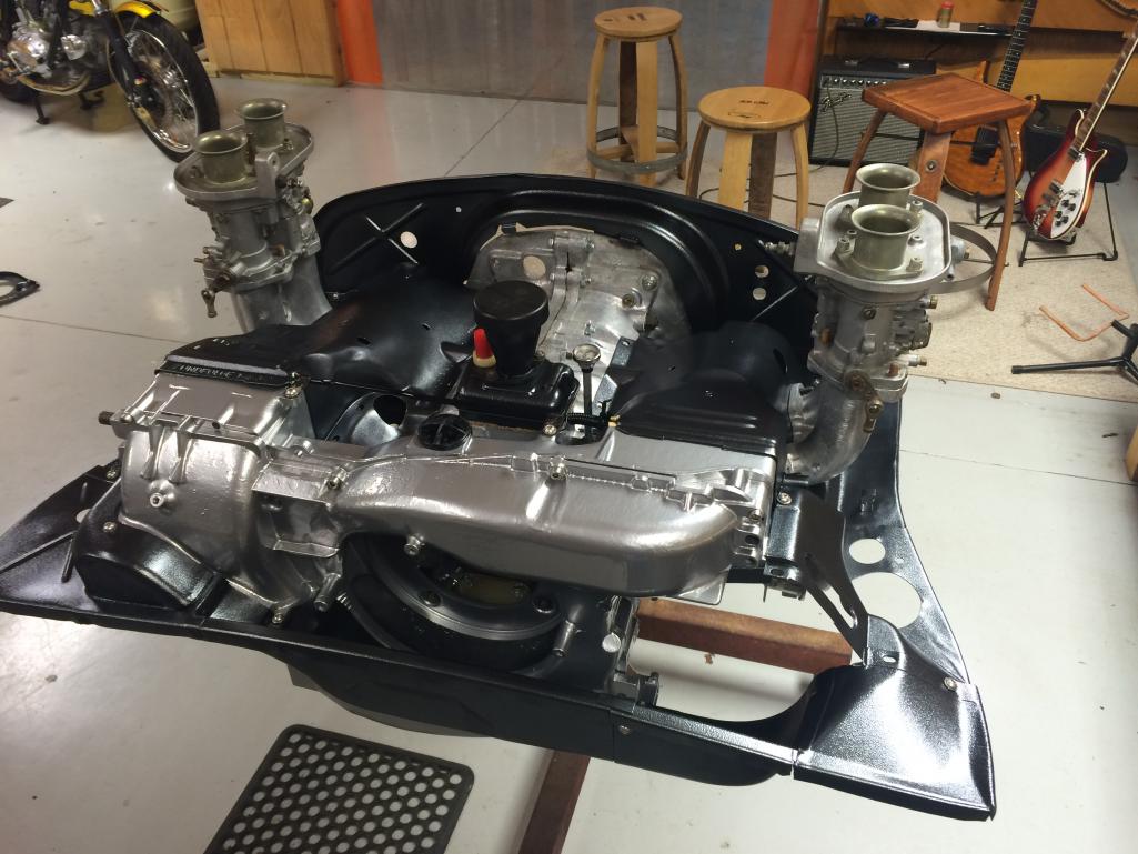
Posted by: sdoolin Aug 27 2016, 03:30 PM
Alternator installed, more tin work fitment, removal, tweaking, re-fitment. Thermostat bracket and alternator cover plate powder coated. Thermostat not hooked up (yet).
Driver side detail pic...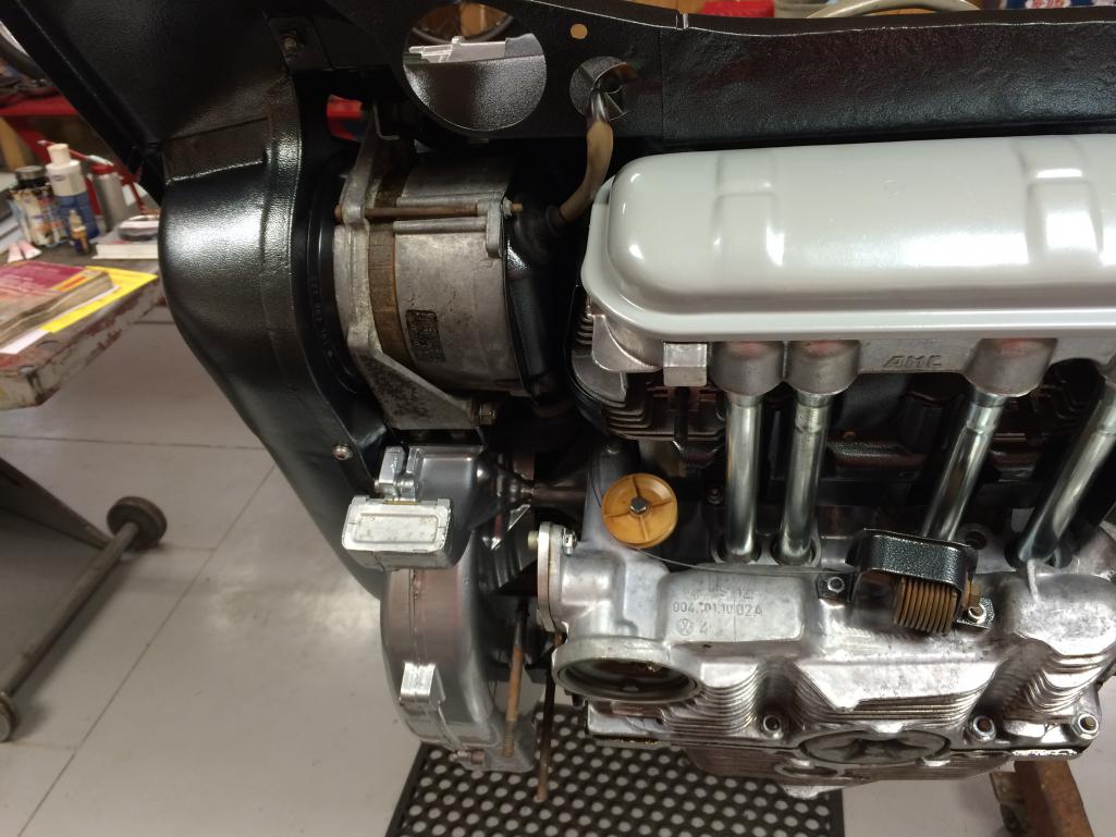
Does anyone make stainless valve cover bales for these engines? Seriously I'd buy 2 pair.
Posted by: sdoolin Sep 18 2016, 08:30 AM
Finally back from my Italian vacation. Took in the F1 race at Monza and decided that F1 drivers are sissies and Porsche Super Cup drivers are real men. I wish they televised the Super Cup races on this side of the pond.
Anyway, more work on engine tin fitment. I have installed and un-installed the tins maybe a dozen times. Tweaking it each time for details that I have always hated. Removed some metal on the tins around the Thermo cable so no rubbing. Removed some metal around intake manifolds to ease gasket & manifold placement.
Also work on mocking up the heat exchangers and various heating system bits. The OE rust on the heater tubes was replaced with powder coat in the color "Porsche Silver". What appears what/grey in the pics actually has a leeeetle metal flake in it, and my powder coat guy clear coated them. Will have to sand away some of the PC for perfect fitment, but I am OK with that. Going with all stainless hardware on this side of the engine as well.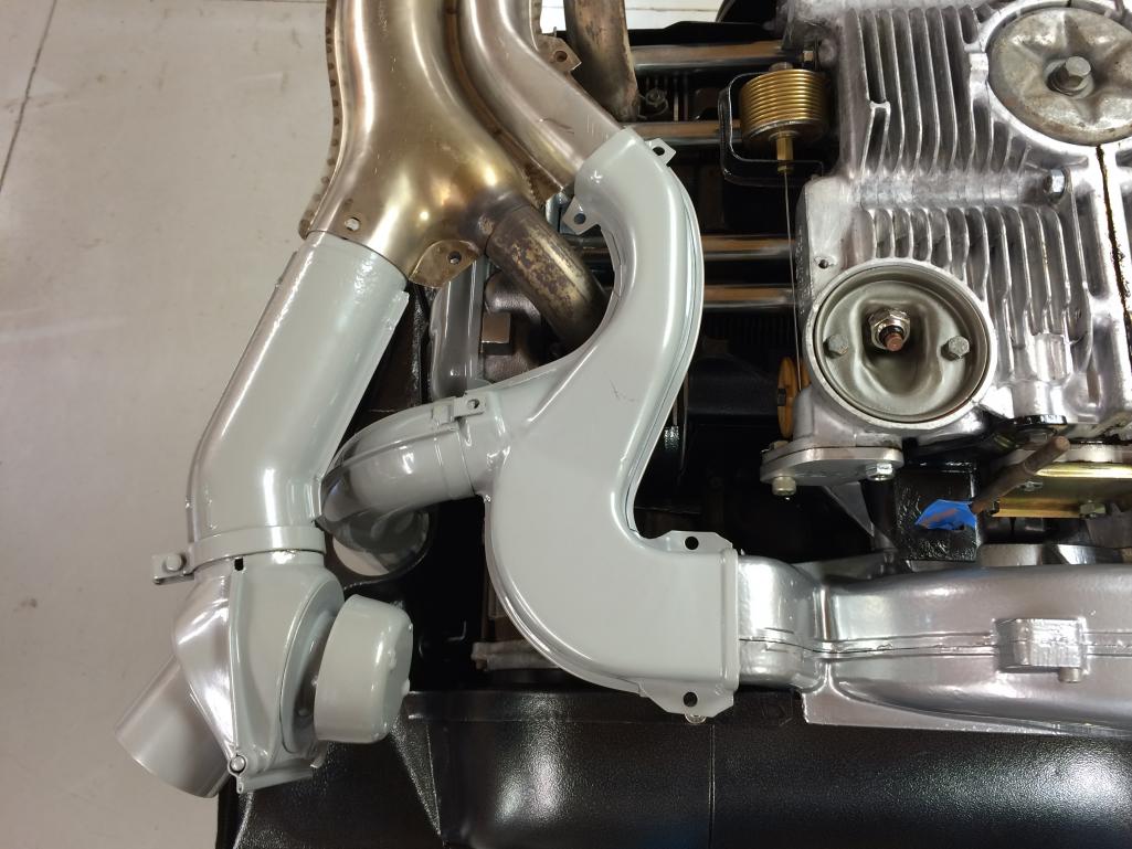
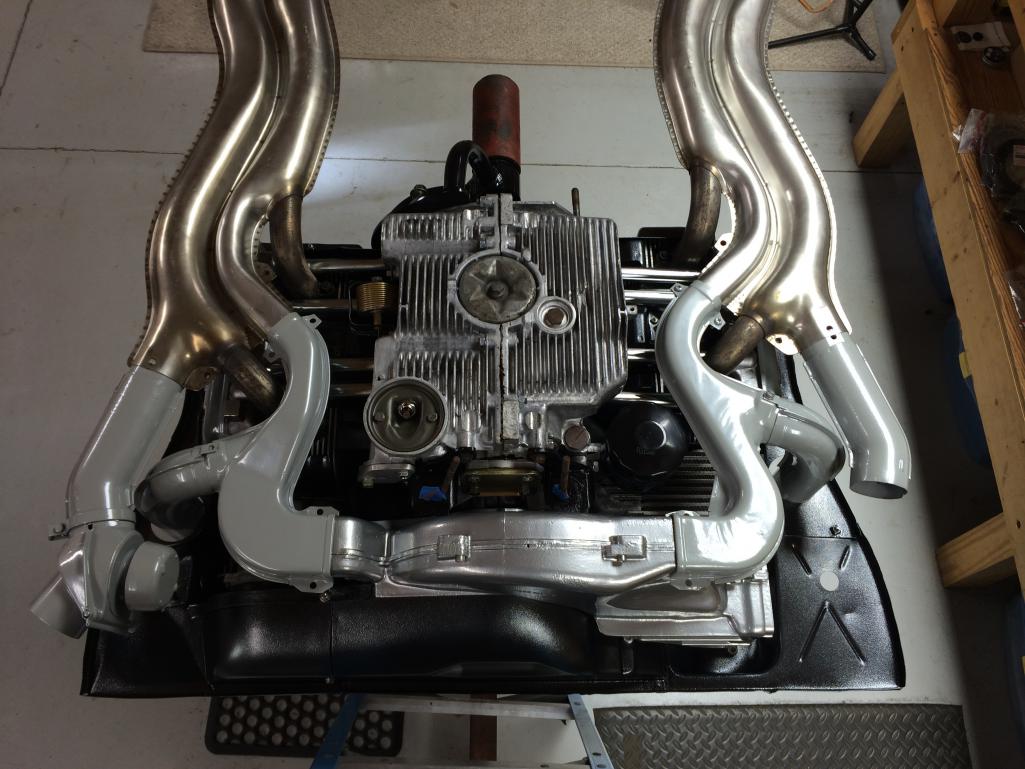
New thermostat & cable from Awesome Powder Coating.
Does anyone know what gasket material was used as OE on the surfaces where the fan housing meets the heat exchanger tube(s)? The two more or less "S" shaped tubes that take forced air from the fan and directs it down the HE? Appeared to me that there was some 40+ year old cork there when I took things apart. Would like to replace it.
Posted by: sdoolin Sep 18 2016, 10:03 AM
Fan, belt, and alternator pulley fitted. I fit a fan guard as was used in the buses. Not sure I will leave it there.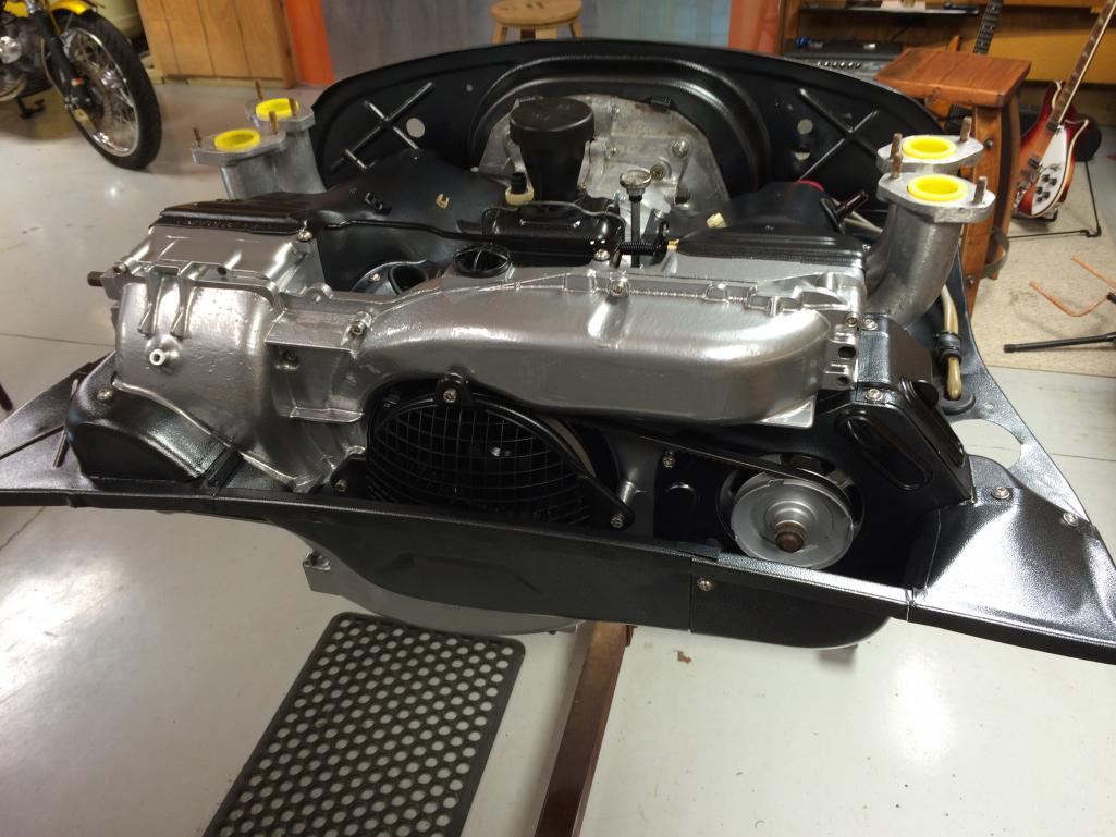
Posted by: sdoolin Sep 18 2016, 10:06 AM
Close up of thermo cable & cooling flaps. I indexed the bar for the flaps, the two white dots mark the cold position when lined up. When warm they will (hopefully) become un-aligned and I'll know the flaps are operating at a glance.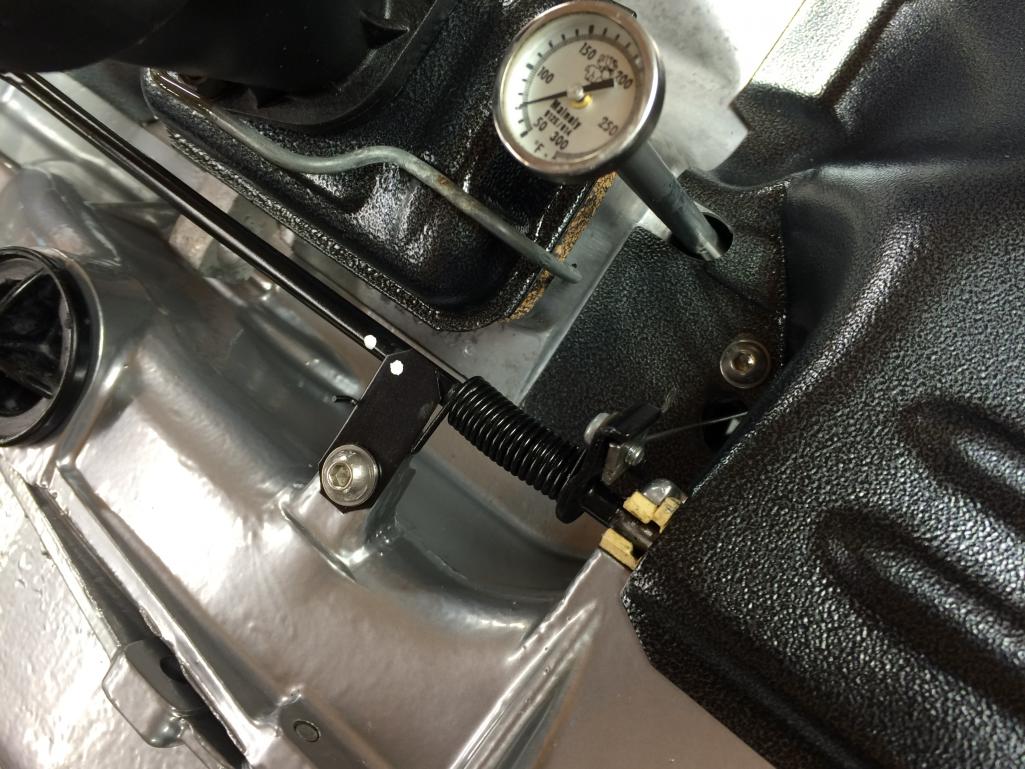
Posted by: Gearhead1432 Sep 18 2016, 03:12 PM
Cork seems like the right gasket material between the fan shroud and heat ducts. Here's a look at what's left of an original gasket.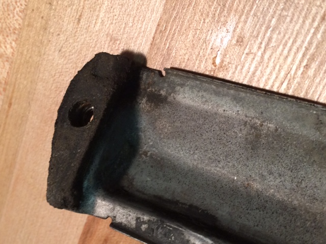
Posted by: Garland Sep 18 2016, 11:30 PM
Cork is correct!
Posted by: sdoolin Sep 19 2016, 06:34 AM
Cork it is then! Thanks gentlemen(?)...
Posted by: sdoolin Sep 22 2016, 12:21 PM
How does the "world" feel about the Bosch 009 dizzy? I had one on my bus engine (all stock except for dual Dells) and while it worked OK, I always attributed a small and annoying flat spot right off idle to that dizzy.
I believe for a street ride some amount of vacuum advance is desirable? The 009 is purely mechanical advance.
As always any/all advice appreciated.
Posted by: sdoolin Oct 23 2016, 09:59 AM
OT - if you ever (EVER) have the chance to turn laps at the Porsche Experience Center in Atlanta, DO IT!
Our local PCA Chapter was gifted 4 tickets to the PEC by our dealer and one of them landed in my pocket. I chose to drive the Macan GTS as I am likely going to buy one in the next few years. They gave me 90 mins. on track with a coach. I was allowed to drive as hard as I felt I could, and I pretty much shredded an expensive set of tires (I have done quite a few DEs in my 993, so going somewhat fast at the racetrack not entirely new to me). No complaints from my coach, no complaints from me. They have several "modules" at the facility including a "handling track (sorta high speed), 2 skid pads (one is wet), a low grip handling circuit, launch control and slalom straight, and a "kick-plate". All very much fun. They do have an off-road track but they would not let me drive the Macan on it, apparently there's a water crossing that is too deep. There is an on-site restaurant, bar, museum and Porsche Classic workshop. They are building a hotel on-site as well.
The Macan and my ugly mug...
Posted by: sdoolin Oct 23 2016, 10:09 AM
So now back on-topic. My 2056 build is nearly complete. I just need to finish a throttle cable bracket, pre-tune the carbs, double and triple check everything, and then I think I can install it back in the car and run it.
And yet I have a conundrum...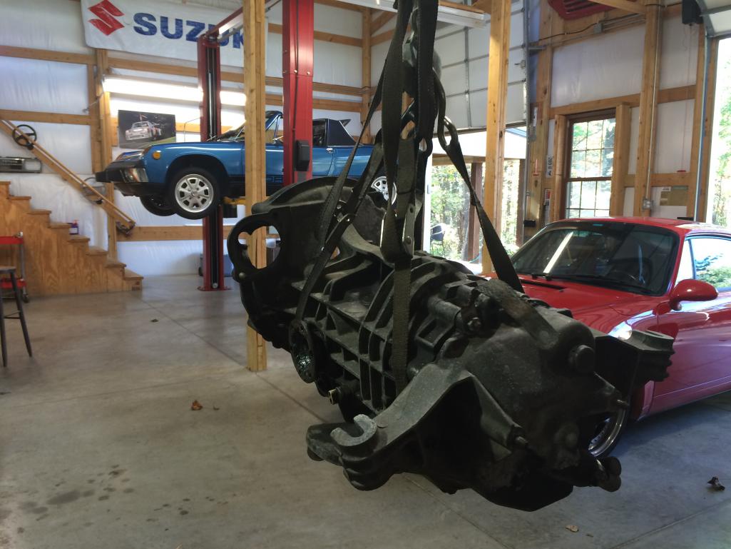
You can see that my transaxle is filthy, and I cannot bring myself to bolt it to the engine (which is spotless) in this condition. So, do I simply clean-up the exterior of it (which will be a painfull process with contact cleaner, simple green and toothbrushes), or do I rip it apart and make any needed repairs (it was working fine) and send the case(s) out to be beadblasted? I kinda hate to tear it apart just to clean it up.
As seen here I have already spent more than an hour doing a rough cleaning, and I am discouraged by the results...
Posted by: HAM Inc Oct 23 2016, 10:38 AM
Steve, one of my customers with a large ultrasonic parts washer, like the one I use, recently sealed the vent on his own tranny and ran it through his large ultrasonic parts washer. It won't hurt the seals or gaskets, and if any fluid did get inside it won't hurt the internals, so why not.
It worked well for him.
If you find a shop with one large enough, be sure to drain the lube before taking it in.
Posted by: sdoolin Oct 23 2016, 11:14 AM
Steve, one of my customers with a large ultrasonic parts washer, like the one I use, recently sealed the vent on his own tranny and ran it through his large ultrasonic parts washer. It won't hurt the seals or gaskets, and if any fluid did get inside it won't hurt the internals, so why not.
It worked well for him.
If you find a shop with one large enough, be sure to drain the lube before taking it in.
Large ultrasonic parts washer. I will search locally for a shop. Thanks for the tip.
Posted by: sdoolin Nov 4 2016, 06:20 AM
Getting very close to being able to install the engine back into the car (just in time for winter of course).
Have distributor installed and timed at 5(ish) degrees BTDC for initial run and cam break in. Carbs are pre-tuned and synched by hand/ear. Am working on a throttle cable bracket that affixes to the right side engine tin (pic below).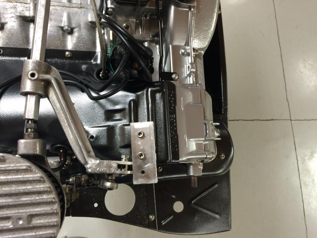
The plate bolts to an existing nut that was used for the coil mount and I added a rivnut next to that for additional stability. The throttle cable will affix to the outermost hole in the bracket. I welded a couple of extensions onto one of the throttle linkage arms to accept the barrel nut. I'm not finished dressing it up yet, but you get the idea. Very clean install, and when I'm done dressing it up it should look pretty much like a factory bit.
Question for those with carbs - do you install carbs before engine in car or do you wait until engine in place and then install? I ask because the carbs are just incrementally wider than the engine tins and it appears that they may hinder installation.
Posted by: sdoolin Dec 11 2016, 04:47 PM
Life keeps getting in the way of me completing this. Plus as soon as I put it back in the car I won't be able to look at it as much...
Throttle cable bracket slotted to match carb tops, linkage lever-arm modified to accept throttle cable. All bits bead blasted to look as if they came together.
I am trying hard to get the engine back in the car this week. Might even hear it run.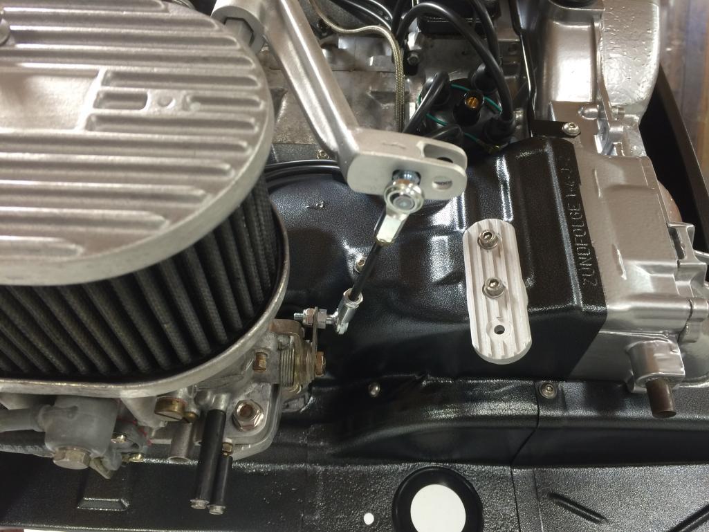
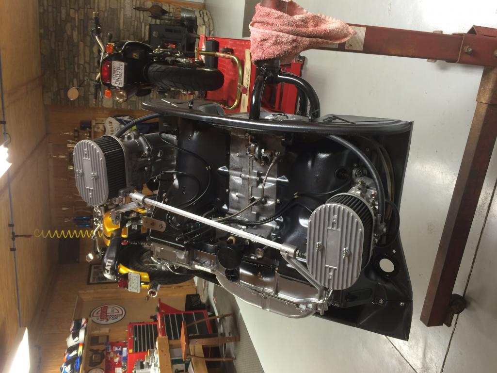
This picture rotated by "the World" for unknown reasons...
I think I saw a thread here on "the World" about a wiring harness "fix" wherein there is a jumper to ground from the relay board. I think I have that handled. I have a low PSI pump to install and I will run return fuel from carbs to tank.
Ignition timing set to (about) 5 degrees BTDC for initial running, cam break-in and first heat-cycle.
BradPenn break in oil ready to go.
Anymore "gotchas" I need to know about before firing her up?
Posted by: sdoolin Dec 20 2016, 10:52 AM
I am getting really close now. These cases haven't seen a transmission in nearly 30 years, so this is a big step.
It is quite aggrevating to me that the "world" rotates pics on a whim. This is a cool pic (in my opinion), but the "world" screws it all up. Stupid.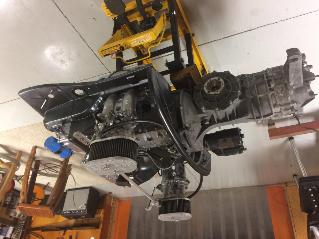
For all you carb experts, is this an acceptable way to block off the vacuum ports? I won't use vacuum signal for anything. I do realize that the mixture screws are missing, they are on the bench.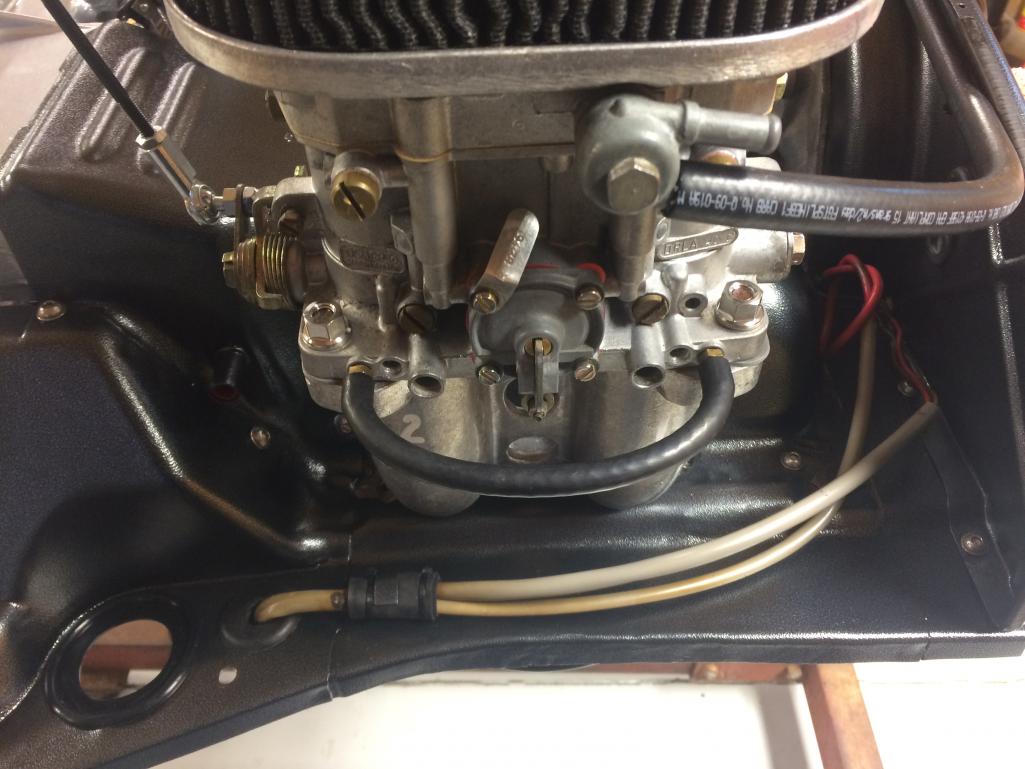
Also wondering about transaxle lube and what is recommended? I'll do a search for it but in the meantime if you happen upon this post and know an answer, feel free to shout it out.
Mounting low pressure fuel pump tonight, re-installing engine bay rubber gaskets, repairing a broken rear trunk hinge, and then I think I can install the engine and transaxle.
Posted by: barefoot Dec 20 2016, 11:27 AM
[And yet I have a conundrum...
You can see that my transaxle is filthy, and I cannot bring myself to bolt it to the engine (which is spotless) in this condition. So, do I simply clean-up the exterior of it (which will be a painfull process with contact cleaner, simple green and toothbrushes), or do I rip it apart and make any needed repairs (it was working fine) and send the case(s) out to be beadblasted? I kinda hate to tear it apart just to clean it up.
As seen here I have already spent more than an hour doing a rough cleaning, and I am discouraged by the results...
[/quote]
I cleaned my tranny case without dipping the whole thing, used a plastic tub and just sprayed simple green type cleaners around and scrubbed & scrubbed till all the grease was gone, then painted it with hi temp aluminum paint, it's still staying clean.
i also put a length of plastic tubing stuck into the top breather fitting and ducted it down to just below the tranny case. Will save future gunk build-up
Posted by: sdoolin Dec 20 2016, 08:38 PM
I ask questions, but don't get many answers. I'm trying not to get a complex over it...
Posted by: cuddyk Dec 20 2016, 09:18 PM
\
Question for those with carbs - do you install carbs before engine in car or do you wait until engine in place and then install? I ask because the carbs are just incrementally wider than the engine tins and it appears that they may hinder installation.
Also wondering about transaxle lube and what is recommended? I'll do a search for it but in the meantime if you happen upon this post and know an answer, feel free to shout it out.
Between the width and height of the carbs, I find it's easier to leave them bolted to the manifolds, and just unbolt the manifolds for installation.
And, as for the transmission lube, I go with Dr. Evil's recommendation for plain ole 90 wt dino.
I need to clean and paint my transmission as well. Any more tips on that? What kind of brush did you use and what did you cover/plug/protect?
Posted by: snakemain Dec 20 2016, 09:54 PM
First time seeing your thread bc I'm not on much, but yeah I'd get a complex too!
All the times I've pulled/installed the engine, I removed carbs/manifolds together. Gets rid of the extra height and seems just simpler for me.
Tranny, I think the way you did is probably what most people end up doing.
My wife and I both super enjoy our Macan S! After 2 years and 35K miles, it's been flawless and is a great combination of super fun to drive, nice on long trips, and fits our 2 kids and stuff in the back if we need to travel. And it'll tow a 914 without protest.
Posted by: sdoolin Dec 21 2016, 06:54 AM
Got it on the carbs, I'll pull the manifolds with carbs intact before installation. I did see the info about old school dino oil for transaxle (80W/90 or straight 90W).
Cleaning transaxle - what a chore. I spent the national debt on contact cleaner and started with that and a couple of very stiff bristle brushes (Kroger). The only thing I covered was the vent. That got the really heavy grimy stuff off. Next step was a toothbrush(es) with more contact cleaner. Finally I went after it with simple green. Using a spray bottle I soaked it for an hour or so - repeatedly spraying it down and finished up with more toothbrush work. Took the better part of a day on again off again. It came out about as well as I could've expected.
Good also to know about the Macan S. I have heard nothing but good things about them and in the next year or 2 I'll pick up a lightly used one.
Posted by: sdoolin Dec 21 2016, 12:43 PM
Any advice or tips on installing new engine compartment rubber seals? I have reconnoitered this briefly and seems like it will be quite painful. Not sure if better to start the rubber bit into the channel and slide along, or just start the upper bit of the rubber all along the channel and press fit the lower lip of the rubber. Kind of hard to explain.
I searched, didn't find anything specific.
Posted by: BeatNavy Dec 21 2016, 02:13 PM
Any advice or tips on installing new engine compartment rubber seals? I have reconnoitered this briefly and seems like it will be quite painful. Not sure if better to start the rubber bit into the channel and slide along, or just start the upper bit of the rubber all along the channel and press fit the lower lip of the rubber. Kind of hard to explain.
I searched, didn't find anything specific.
Don't try to slide the seal. Place the lower lip in the channel and press upper lip in with a blunt tool (preferably something that WON'T puncture the seal). It takes a little time but it is only a minor PITA.
Posted by: sdoolin Dec 21 2016, 03:29 PM
Any advice or tips on installing new engine compartment rubber seals? I have reconnoitered this briefly and seems like it will be quite painful. Not sure if better to start the rubber bit into the channel and slide along, or just start the upper bit of the rubber all along the channel and press fit the lower lip of the rubber. Kind of hard to explain.
I searched, didn't find anything specific.
Don't try to slide the seal. Place the lower lip in the channel and press upper lip in with a blunt tool (preferably something that WON'T puncture the seal). It takes a little time but it is only a minor PITA.
Thanks, I'll give that a shot tonight.
Posted by: sdoolin Dec 24 2016, 04:13 PM
Engine is in. Bottom side is all buttoned up (heat exchangers, ductwork for heat, muffler, cables and shift rod. All good. I'll post pics a little later. Right now I have a question about wiring. There is a small in-enginebay wiring loom that connects to the rear of the relay board with a multi-pin connector. Off of this loom comes the reverse light wires, starter wires, and (I believe) oil pressure switch and coil wires.
My question is specific to the coil wires. There are two. One I assume for each "side" of the coil. The coil is numbered 1 on one side and 15 on the other (I think). Both wires are either black, or so dirty no amount of contact cleaner will reveal their original color.
Does it matter which of these wires goes to which side of the coil?[i] Yes, electrical stuff is my weak point. If I can get this sorted out, I'll start the car tonight or tomorrow.
Posted by: dlee6204 Dec 24 2016, 04:22 PM
Engine is in. Bottom side is all buttoned up (heat exchangers, ductwork for heat, muffler, cables and shift rod. All good. I'll post pics a little later. Right now I have a question about wiring. There is a small in-enginebay wiring loom that connects to the rear of the relay board with a multi-pin connector. Off of this loom comes the reverse light wires, starter wires, and (I believe) oil pressure switch and coil wires.
My question is specific to the coil wires. There are two. One I assume for each "side" of the coil. The coil is numbered 1 on one side and 15 on the other (I think). Both wires are either black, or so dirty no amount of contact cleaner will reveal their original color.
Does it matter which of these wires goes to which side of the coil?[i] Yes, electrical stuff is my weak point. If I can get this sorted out, I'll start the car tonight or tomorrow.
One of the wires should be black/purple stripe. This goes to the negative side of the coil.
Posted by: sdoolin Dec 24 2016, 04:25 PM
Engine is in. Bottom side is all buttoned up (heat exchangers, ductwork for heat, muffler, cables and shift rod. All good. I'll post pics a little later. Right now I have a question about wiring. There is a small in-enginebay wiring loom that connects to the rear of the relay board with a multi-pin connector. Off of this loom comes the reverse light wires, starter wires, and (I believe) oil pressure switch and coil wires.
My question is specific to the coil wires. There are two. One I assume for each "side" of the coil. The coil is numbered 1 on one side and 15 on the other (I think). Both wires are either black, or so dirty no amount of contact cleaner will reveal their original color.
Does it matter which of these wires goes to which side of the coil?[i] Yes, electrical stuff is my weak point. If I can get this sorted out, I'll start the car tonight or tomorrow.
One of the wires should be black/purple stripe. This goes to the negative side of the coil.
Thanks, which is the negative side? If it is obvious I am missing it.
Posted by: BeatNavy Dec 24 2016, 04:33 PM
Black/Purple is the tach wire and goes to negative (-) side, terminal 1 on coil.
Black is hot (+) and goes to terminal 15 on coil.
Posted by: cuddyk Dec 24 2016, 04:34 PM
Look for the "-" symbol near the posts on the coil.
Posted by: sdoolin Dec 24 2016, 04:36 PM
Black/Purple is the tach wire and goes to negative (-) side, terminal 1 on coil.
Black is hot (+) and goes to terminal 15 on coil.
Sweet. Now I just got to see if I can identify black/purple. Thanks VERY much for the assist. Dizzy wire goes to 1 or 15?
Posted by: BeatNavy Dec 24 2016, 04:40 PM
Black/Purple is the tach wire and goes to negative (-) side, terminal 1 on coil.
Black is hot (+) and goes to terminal 15 on coil.
Sweet. Now I just got to see if I can identify black/purple. Thanks VERY much for the assist. Dizzy wire goes to 1 or 15?
It connects to the same spade as on terminal 1 (negative).
Here's a reference: http://www.pelicanparts.com/914/parts/Electrical/914_electric_73C.jpg
Coil is #6 in the diagram, dizzy is #5.
Posted by: sdoolin Dec 24 2016, 04:48 PM
Black/Purple is the tach wire and goes to negative (-) side, terminal 1 on coil.
Black is hot (+) and goes to terminal 15 on coil.
Sweet. Now I just got to see if I can identify black/purple. Thanks VERY much for the assist. Dizzy wire goes to 1 or 15?
It connects to the same spade as on terminal 1 (negative).
Here's a reference: http://www.pelicanparts.com/914/parts/Electrical/914_electric_73C.jpg
Coil is #6 in the diagram, dizzy is #5.
Perfect, thanks so much.
Posted by: BeatNavy Dec 24 2016, 05:10 PM
Good luck with the initial start  Look forward to hearing how it goes...
Posted by: sdoolin Dec 24 2016, 06:28 PM
It RUNS! Took it awhile to sputter to life, and it missed quite a bit for the first few minutes, but it ran at a little over 2k RPM for 15 mins. The idle speed on the carbs was set very high, so I just let it run at high idle for cam break in. I turned the idle speed down from side to side and got it to idle nicely at just about 1k RPM. Takes throttle reasonably well, revs out nicely and returns quickly to low idle. So initial carb setting is in the ball park. Ignition timing also in the ballpark since it ran, but I need to advance that when I have put a few more heat cycles on it.
One small fuel leak (I have installed serviceable glass fuel filters on each side of the carbs, and one has a small leak). No oil leaks that I can find. But man is it noisy at the rocker covers. So I need to investigate that. I suspect that my valve adjusters are contacting the rocker covers which is going to be a bummer. This build has chromoly pushrods so (I think) the spec for valve clearance is 0. I will obviously double check.
For now it runs. Merry Christmas to me and thanks to everyone here that has offered advice and assistance.
I'll post a few pics later, right now I think I am gonna celebrate with some tasty adult beverages.
Posted by: sdoolin Dec 24 2016, 08:19 PM
few pics of the install from the underside...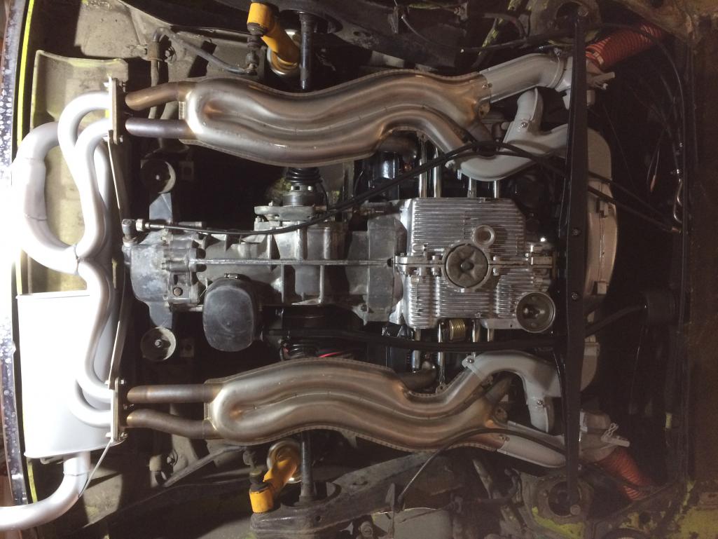
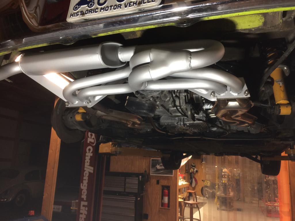
Posted by: sdoolin Dec 27 2016, 12:25 PM
Noise from the left side rocker cover investigated. Seems one of my valve adjusting lock nuts wasn't locked, allowing for a tad too much clearance between valve and adjuster on the exhaust valve on #2. Since I ran it this way for the better part of 10 - 15 mins, I removed that rocker shaft with rockers and inspected. Also inspected the pushrod. All seems OK thankfully.
I have probably 5 good heat cycles on it now. Drove it today for 10 miles and I am (I hate to say) underwhelmed so far. But, the timing is only set by feel/eyeball and I am running an 009 dizzy. Which I hate. At small throttle openings it stumbles and bogs, then clears out and pulls (sorta hard). It is driveable, but not all that it can be I don't think.
All of the oil appears to stay inside the engine, no fuel leaks, and the carbs feel very close to dead-on.
Someone sell me a proper dizzy? Please? Friends don't let friends drive around with Bosch 009s in their cars...
Posted by: porschetub Dec 27 2016, 02:03 PM
Really nice work,you have a truly handbuilt blueprinted engine which sets it aside from "just an average" rebuild.
The 009 is ok but just,these were made for industrial engines that run @ constant RPM around 3600,I did read that people in the know can get them to work by slowing the full advance which comes in too quickly for a street driven engine.
You could try increasing the spring tension on one of the internal counterweights to get the advance "all in" @ higher RPM,I did that years ago with some success on a 010 which is basically the old version of the 009.
Failing any improvement with the 009 you could run a vacuum assisted distributor but you then have the hassle of finding vacuum points on both your carbs,my Dellorto's have them but I'am not sure about the Webers cause I've never run them on a T4.
If you buy a vacuum dizzy look for the Bosch one with a 205 end number (from memory),I have one converted to Hotspark pointless ignition that will go on my 1800 as I have a 009 on there now.
The cheap Chinese made SVDA (?) is used with good results on the T1 motors but I don't know about the T4 perhaps some on here can chime in.
Posted by: RoadGlue Dec 27 2016, 02:31 PM
Failing any improvement with the 009 you could run a vacuum assisted distributor but you then have the hassle of finding vacuum points on both your carbs,my Dellorto's have them but I'am not sure about the Webers cause I've never run them on a T4.
I've always had good luck running FI dizzies with vacuum advance on my 40 IDFs. I just take vacuum off one side. I don't think it needs to be taken off both, but I could be wrong! :-)
Posted by: sdoolin Dec 27 2016, 04:22 PM
Failing any improvement with the 009 you could run a vacuum assisted distributor but you then have the hassle of finding vacuum points on both your carbs,my Dellorto's have them but I'am not sure about the Webers cause I've never run them on a T4.
I've always had good luck running FI dizzies with vacuum advance on my 40 IDFs. I just take vacuum off one side. I don't think it needs to be taken off both, but I could be wrong! :-)
So - RoadGlue - you are saying you run the OE FI dizzy? I have duel Dellorto 40 DRLAs. They each have 2 vacuum ports at the base just below the throttle plates. It is worth a shot then to re-install the dizzy I took off the engine (nicely running FI 2.0), plug one vacuum port on it and connect the other to a single vacuum port on one of the carbs? Is this a pretty common solution?
I have been tuning carbs and ignition timing all day. The 009 flat-spot will not go away. I can't see having invested this much time and energy into this build just to sacrifice driveability because of the stinking distributor.
Posted by: RoadGlue Dec 27 2016, 04:27 PM
So - RoadGlue - you are saying you run the OE FI dizzy? I have duel Dellorto 40 DRLAs. They each have 2 vacuum ports at the base just below the throttle plates. It is worth a shot then to re-install the dizzy I took off the engine (nicely running FI 2.0), plug one vacuum port on it and connect the other to a single vacuum port on one of the carbs? Is this a pretty common solution?
I have been tuning carbs and ignition timing all day. The 009 flat-spot will not go away. I can't see having invested this much time and energy into this build just to sacrifice driveability because of the stinking distributor.
I'd absolutely give it a try! My previous carb cars all ran stock FI distributors, but I can't remember which models.
I'm sure you can find an advance curve chart somewhere, but I'm at work and can't really dig around right now.
I'm also not familiar with Dellorto's enough to say which ports you should be using (perhaps they're all the same...).
Great build. Been following since the beginning.
Posted by: sdoolin Dec 27 2016, 04:35 PM
So - RoadGlue - you are saying you run the OE FI dizzy? I have duel Dellorto 40 DRLAs. They each have 2 vacuum ports at the base just below the throttle plates. It is worth a shot then to re-install the dizzy I took off the engine (nicely running FI 2.0), plug one vacuum port on it and connect the other to a single vacuum port on one of the carbs? Is this a pretty common solution?
I have been tuning carbs and ignition timing all day. The 009 flat-spot will not go away. I can't see having invested this much time and energy into this build just to sacrifice driveability because of the stinking distributor.
I'd absolutely give it a try! My previous carb cars all ran stock FI distributors, but I can't remember which models.
I'm sure you can find an advance curve chart somewhere, but I'm at work and can't really dig around right now.
I'm also not familiar with Dellorto's enough to say which ports you should be using (perhaps they're all the same...).
Great build. Been following since the beginning.
Thanks so much. I'm going to give it a shot this week. If you (or if anyone) has any more info please share.
Posted by: maf914 Dec 28 2016, 07:04 AM
Very nice work. Good luck with your distributor efforts.
May I ask how you refinished your Bursch exhaust? Looks good! Thanks
Posted by: sdoolin Dec 28 2016, 07:23 AM
Very nice work. Good luck with your distributor efforts.
May I ask how you refinished your Bursch exhaust? Looks good! Thanks
Thanks for the compliment. The Bursch was high temp ceramic coated by the same guy that does my powder coat work. I can get the exact brand/color of the coating if interested.
Posted by: sdoolin Dec 28 2016, 12:02 PM
I found this on a shelf with 4 - 5 derelict Solex carbs for beetles (or something). I suspect it is either off this exact engine (1976 bus cases used in this thread), or my other bus engine (1979). When I first built the '79 (in 1986), I removed whatever dizzy was on it 'cause I was convinced that the 009 was the way to go. I spent years and years driving around a flat spot in that bus.
This likely needs some love, and I can send it out for service but wondering if it is more desirable (for driveability) than re-using the OE FI dizzy?
So my options now are:
1) re-use OE FI Dizzy
2) service this one (in the pics) and use it
3) run the 009 (not really an option).
As always all assistance appreciated...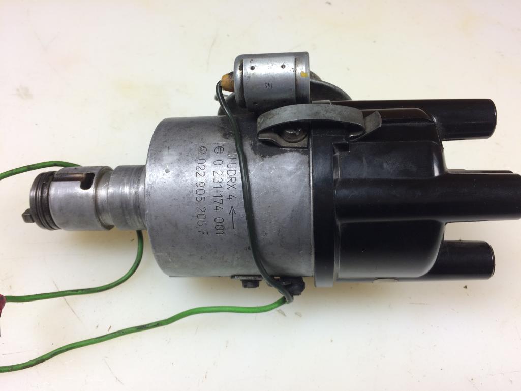
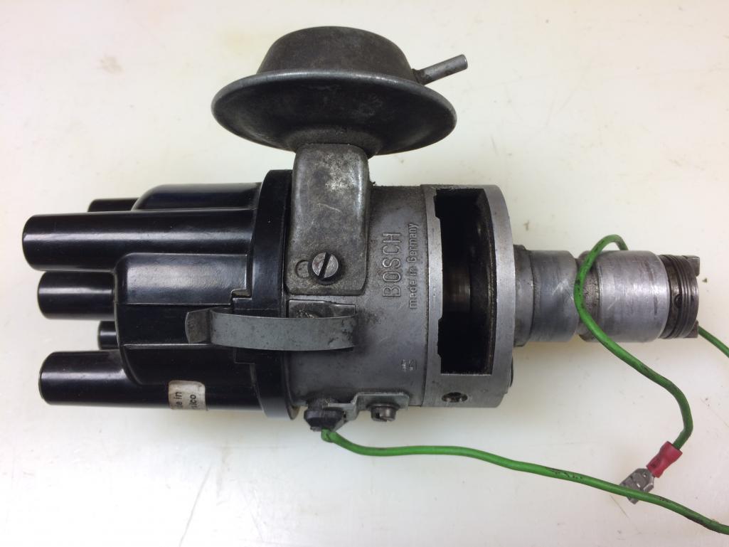
Posted by: MarkV Dec 28 2016, 12:43 PM
I have DRLA 40's and have never been able to see a vacuum signal from those 4 ports on the sides of the carbs. I have vacuum plugs on them.
The biggest improvement I ever got in drivability and performance was to get rid of my Bosch distributor and weak ignition coil. I was running a 050 with a blue coil. It had a flat spot off idle and it took a while to warm up and hold an idle. I switched to a Mallory dual point because they quit making the electronic version. I set it up with the gray springs and converted it to a Pertronix II with a Pertronix low impedance coil. No more flat spot and it will hold an idle sooner and it accelerates better than it did with the 050.
Posted by: sdoolin Dec 28 2016, 01:23 PM
I have DRLA 40's and have never been able to see a vacuum signal from those 4 ports on the sides of the carbs. I have vacuum plugs on them.
The biggest improvement I ever got in drivability and performance was to get rid of my Bosch distributor and weak ignition coil. I was running a 050 with a blue coil. It had a flat spot off idle and it took a while to warm up and hold an idle. I switched to a Mallory dual point because they quit making the electronic version. I set it up with the gray springs and converted it to a Pertronix II with a Pertronix low impedance coil. No more flat spot and it will hold an idle sooner and it accelerates better than it did with the 050.
Strange about no vacuum from those 4 ports. There is also a 5th port on what I generally consider the right side carb. It has a rubber plug over it.
I don't think the Mallory as available any longer? I have been hoping someone has one on a shelf somewhere and would be ready to sell it to me...
Posted by: MarkV Dec 28 2016, 05:03 PM
Strange about no vacuum from those 4 ports. There is also a 5th port on what I generally consider the right side carb. It has a rubber plug over it.
I don't think the Mallory as available any longer? I have been hoping someone has one on a shelf somewhere and would be ready to sell it to me...
[/quote]
The Mallory wasn't available when I bought mine either. The dual point is the same distributor only not electronic. They still sell a kit to convert a Mallory dual point to a Pertronix. The Mallory Unilite works on an LED which I have heard is more prone to failure than the Pertronix. The Mallory has a bigger cap with more distance between the leads and more robust bearings...It also has a built in adjuster for the range of advance that makes it easy to set up.
Posted by: sdoolin Dec 28 2016, 08:01 PM
Pic of the engine installed from the top side. Pay no attention to the Brad Penn oil bottle crankcase breather apparatus. It is temporary (and it works). I will fabricate a proper crankcase breather box in the coming weeks.
Custom throttle cable bracket and linkage arm work great. Carbs are nicely synched and she idles very smooth from side to side and takes throttle smoothly also. Engine and transaxle have solid mounts from PO, I may change that. Even with solid mounts vibration not too bad with carbs synched well.
For now, she runs. Pretty well. Pulls stronger almost each time I drive her and if it weren't for the freak'n 009 dizzy I'd call this done! Heat works well and I will drive her all winter - in between salting and brining.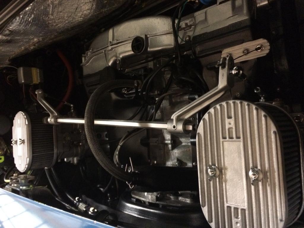
Oh, and my trunk light works. Never knew until tonight...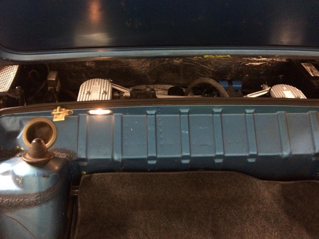
Posted by: sdoolin Dec 29 2016, 09:54 AM
Going for another test/tune sortie...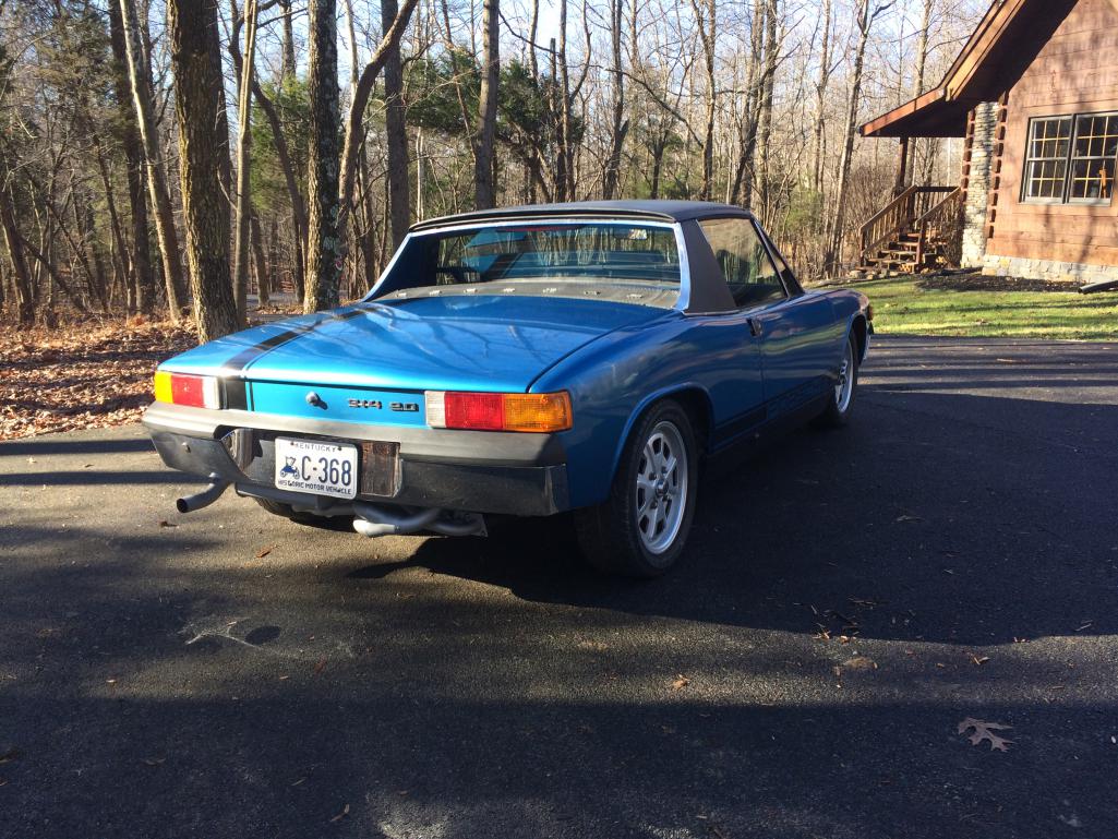
Posted by: RoadGlue Dec 29 2016, 12:04 PM
If the vacuum canister is working on the FI dizzy then you might as well just give it a light cleaning and see how it works before you spend time refurbishing it.
I thought for sure you'd get more input on this. The board must be in hibernation for the holidays.
Posted by: sdoolin Dec 29 2016, 12:52 PM
Yes RoadGlue, I had thought that asking about which dizzy to use might attract us much attention as my "1mm step in the cylinder heads" bit from months ago. My plan is to re-use the FI dizzy with a light cleaning. I know it was functioning well on that engine.
My real desire is to understand if the dizzy pictured a few posts ago with the last digits of "205" stamped on it is a contender, if it might be better suited than the FI dizzy (2 vacuum posts), and if yes (it is a contender and better suited), I'll have it fully serviced - which is kinda pricey.
I will fit the FI dizzy soon and do some driving...
Posted by: sdoolin Dec 29 2016, 04:14 PM
Removed 009 dizzy, installed OE FI dizzy. Timed to just about 32 BTDC at 3500 RPM. Better. Pronounced flat spot gone, but still a slight hesitation or flat spot at small throttle openings. I have 100 miles on it since the engine went back in. It keeps getting better with every outing.
Have discovered 2 small oil leaks, both of them on the cylinder head side at push rod tube seals. Very small to be sure. Disappointing. Somewhat expected, but still disappointing.
Have checked and re-checked snugness of all exhaust nuts/bolts (head and muffler side). All good.
For now I am going to just drive it. I filled up the gas tank and am going to burn through that this weekend (if the weather permits). At 500 miles I will drain the break-in oil, change the filter and pour in some Brad Penn 20W50.
Note that dual Dellortos running at WOT just about a foot behind your head are LOUD. Music to my ears, but LOUD. Many of you know this already...
Posted by: RoadGlue Dec 29 2016, 04:53 PM

Okay, that's a good start! Until you get an AF meter on the exhaust you're going to be fighting unknown demons.
Have your rings seated yet? Are you running a head temp gauge?
Love the sound of four throttle bodies wide open inches from the back of your head.
Keep us updated!
Cheers,
Randy
Posted by: ericoneal Dec 30 2016, 06:23 PM
Did I see you out on HWY 22 in Crestwood toda?. Startled me to see a 914 pass by me...
Posted by: sdoolin Dec 31 2016, 08:30 AM
Did I see you out on HWY 22 in Crestwood toda?. Startled me to see a 914 pass by me...
Probably me. I put about 100 miles on the car today, all local and close to home (LaGrange, Buckner, Crestwood). I have the HP now to pass other cars at will.

Posted by: sdoolin Jan 19 2017, 09:17 AM
On a short night drive last night and as I pulled up the driveway I lost all lights. Pulled into shop and switched it off, then tried to re-start. No luck, battery dead.
I have a sneaking suspicion that the super cool powder coating that I had applied to the alternator (generator(?)) bracket means that i am not charging while driving (or ever).
So, alternator (generator(?)) has to come out. This seems like it'll be a pain without removing the engine, I'll reconnoiter it over the weekend...
Posted by: RoadGlue Jan 19 2017, 10:58 AM
Interesting. I don't think that the alternator is grounded through the bracket. Powdercoating them is common.
Did you install a new alternator? There's an issue wherein one of the binding posts inside newer alternators can touch and ground out on the stator cover. Might be that.
Posted by: sdoolin Jan 19 2017, 11:20 AM
Interesting. I don't think that the alternator is grounded through the bracket. Powdercoating them is common.
Did you install a new alternator? There's an issue wherein one of the binding posts inside newer alternators can touch and ground out on the stator cover. Might be that.
I wouldn't have thought the PC would be an issue either. Did not use new alternator. Had one on the shelf, had it tested (positive) and used it. I'll start to troubleshoot over the weekend (I hope). Unfortunately while I am comfortable building an engine up from all of its component parts/pieces, the electrical systems baffle and frustrate me. I do own a reasonably good quality multi-meter so I guess I will break it out.
Posted by: BeatNavy Jan 19 2017, 11:20 AM
From what I've read the alternators are normally grounded through the bracket and that this can be a problem unless you fashion a separate grounding path with a cable tied to somewhere else (e.g., fan housing).
It's a pretty simple check with a voltmeter to see if you're charging. Do some testing before fighting with the alternator. I had a battery that kept running down a few months ago that had me wondering if my charging system was working or not. Turns out alternator was fine. It was a bad parasitic drain from radio. Just a few checks with a multimeter helped isolate.
Posted by: RoadGlue Jan 19 2017, 11:36 AM
From what I've read the alternators are normally grounded through the bracket and that this can be a problem unless you fashion a separate grounding path with a cable tied to somewhere else (e.g., fan housing).
Then I stand corrected.
You can probably snake a grounding cable through the tension adjustment panels to just see if grounding the alternator chassis starts the charging process. If it works, then route it stealthily underneath the car. Shouldn't require pulling the motor (thankfully).
Posted by: sdoolin Feb 8 2017, 09:05 AM
Update on charging issue. Definitely was not charging, voltmeter across battery was 12V with engine running. Keep in mind that I powder coated the fan housing and both the alt. brackets. So just removing PC from the bracket(s) was not going to get it done.
I added a ground wire from one of the Alt cover plate bolts up the grounding stud located above the relay board. Charging again! What is strange is that I get more than 14V across the battery with my voltmeter, but the gauge in the car reads about 2V lower.
Now I am seeing a small oil leak from the rear of the engine. I hope it stays small or goes away (right....).
Posted by: Keith914 Feb 8 2017, 09:58 AM
What if any "gasket" solution did you use on the pushrod tube O rings? I am about to replace old pushrods with new Vicon O rings (recently carefully installed with engine oil lubrication only -- leaking!), with new pushrods and Vicon O rings. Much advice from engine builders who use Yamabond or similar vs. experts here who say just smeer with engine oil!!
Posted by: sdoolin Feb 8 2017, 10:51 AM
What if any "gasket" solution did you use on the pushrod tube O rings? I am about to replace old pushrods with new Vicon O rings (recently carefully installed with engine oil lubrication only -- leaking!), with new pushrods and Vicon O rings. Much advice from engine builders who use Yamabond or similar vs. experts here who say just smeer with engine oil!!
I simply used the O-Rings that came with my gasket set (VR set). No Yamabond or RTV in my build(s). I smear a little grease on them for installation and make sure to use the wire pushrod tube "keepers" inside the rocker box. I am experiencing very small (and hugely disappointing) leaks from several of them.
Posted by: Keith914 Feb 8 2017, 11:02 AM
What if any "gasket" solution did you use on the pushrod tube O rings? I am about to replace old pushrods with new Vicon O rings (recently carefully installed with engine oil lubrication only -- leaking!), with new pushrods and Vicon O rings. Much advice from engine builders who use Yamabond or similar vs. experts here who say just smeer with engine oil!!
I simply used the O-Rings that came with my gasket set (VR set). No Yamabond or RTV in my build(s). I smear a little grease on them for installation and make sure to use the wire pushrod tube "keepers" inside the rocker box. I am experiencing very small (and hugely disappointing) leaks from several of them.
Forrest recently used a sealant on one side and just oil on the other side. Oil only side is leaking! I will use sealant this time and report back.
Posted by: sdoolin Apr 25 2017, 04:53 PM
An update (and a question of course). I have 1200(ish) miles on the engine now. It has been doing quite well. Changed oil from Brad Penn break in oil to Brad Penn 20w50 at 500 miles. Leaned out the idle and the main jets on the Dells recently as weather warmed up and it lost a little of its "edge". Running quite well. Now instead of wondering if I can pas cars ahead, I simply downshift and go. Very liberating.
Anywho, last night during a spirited drive wherein I may have (possibly, maybe) caught a little air (rear wheels maybe an inch off the ground), she started running on 3.
Cylinder number 1 acting poorly. Checked spark - good bright blue spark at the plug. Checked plug - looks good (perhaps even a little lean). Checked fuel, throttle plate is wet, accel pump is working. Placing hand over velocity stack yields no results (it should kill the engine), and turning the mixture adjuster all the way in on that cylinder does not change behavior. There is an occasional backfire (sometimes even with an exciting/scary flame) through the carb at open throttle positions, none at closed throttle.
Now, getting a little air and the subsequent running only on three are quite possibly, and hopefully not related, but I'm curious as to what you guys think may be the problem here. I will check compression next. Running chromoly pushrods so valve lash should be 0, will check that also. No strange/abnormal noises (like something broken) before, during, or after getting air.
This is what I get for saying to myself "I should post a follow-up to "the world" about how great my car is running"....
Posted by: RoadGlue Apr 25 2017, 05:01 PM
Now that IS a strange one indeed. Maybe pull off the rocker cover and poke around and make sure there isn't a stuck valve. Perhaps something came loose in the bump and squished a push rod tube... That's a long shot of a guess though.
Even though the accelerator pump is working, maybe a jet got clogged with debris during the "landing."
Crossing my fingers for you that it's nothing too serious.
Posted by: sdoolin Apr 26 2017, 05:53 AM
Did some more troubleshooting last night. Removed all main jet stacks and idle jets. Cleaned all of them. Changed idle jets back to 60s (from 55s). Re-installed all. Now the thing wont idle. Runs on all 4 now, and takes throttle well, just won't hold an idle. Note that for the first 800 miles it idled quite nicely with 60s. So, I will dig deeper.
Never (ever) proclaim to oneself that your antique aircooled German car is "running flawlessly". This is what happens....
Posted by: ottox914 Apr 26 2017, 07:10 PM
Check compression. Or first, pull valve cover off and check the rockers. Not to be the death fairy, but could be a bent or damaged valve or seat. Eliminate as many possible failure points as you can. If it's really running on 4 now, might not be valve related. But nice to cross that off the list of possible problems. Perhaps cheaper answers remain to be found.
Posted by: stugray Apr 27 2017, 11:18 AM
sdoolin -
Are you running gas with ethanol?
Posted by: sdoolin Apr 27 2017, 12:28 PM
Almost certainly running gas with ethanol, I don't shop anywhere specific for gasoline. I put 93 octane in it, but I'm not sure that means no ethanol? It sure ran well for like, 1100 miles...
Car was back to running on 3 at idle, so I took carbs off last night and thoroughly cleaned and inspected. Re-installed them and only running worse.
This is feeling more and more like a compression issue. So I checked compression on cyls 1 & 2. Both 0. Then I remembered my compression guage is a piece of crap/broken. So time to buy a new cool one. I am thinking more and more that my valve lash is set wrong and one or more valves not closing completely. But I need to (obviously) get into the rocker covers to sort that out.
Anyone have a fav. compression guage?
Posted by: Dave_Darling Apr 27 2017, 04:59 PM
Does the starter crank unevenly? If you get a sound from it like "RR-RR-RR-..-RR-RR-RR-.." you have a cylinder with zero compression.
(Don't ask how I know.)
--DD
Posted by: stugray Apr 28 2017, 10:42 AM
Almost certainly running gas with ethanol, I don't shop anywhere specific for gasoline. I put 93 octane in it, but I'm not sure that means no ethanol? It sure ran well for like, 1100 miles...
If you run ethanol in carb engines you are almost certain to get clogged jets.
This can happen in less than one tank.
The alcohol absorbs water, then the gas in the float bowls evaporates leaving behind the water.
Water corrodes aluminum in carb bowls leaving behind a white residue.
White residue clogs jets.
Fuel filters dont help.
Posted by: sdoolin Apr 28 2017, 01:37 PM
Stugray - thanks for the 'splanation. This may come down to clogged jets, or something in the fuel system and to be sure, I hope it is that small of an issue.
To DDs point - the car cranks and starts evenly, and quickly, no strange noises there.
Having failed at determining compression in any cylinder due to lack of proper tools, I went ahead and inspected all rockers, swivel feet, pushrods, etc. I had somewhat hoped to find an overly tight valve clearance that would effectively hold a valve open and a loss of compression. No luck. All swivel feet spin nicely on the their valves, and all pushrods spin nicely in the rockers. Chromoly pushrods.
She still runs on only 3. All the time. Will not hold an idle.
Interestingly there is a very odd noise when she dies (won't idle). There's a "squishing" or "squeezing" noise from somewhere behind the engine tins, as if fluid is being forced through some small orifice. Goes away after a few seconds.
Sooooo, until I acquire a proper compression tester I am somewhat shooting in the dark and only guessing. I have cleaned the carbs thoroughly, but may attempt that again. A compression tester ordered from Amazon will take a few days to arrive, so the car is down for awhile.
I will re-iterate, never ever proclaim to oneself (or anyone else) that your antique german aircooled car runs flawlessly. There is a price to be paid...
Posted by: sdoolin Apr 30 2017, 02:14 PM
Compression numbers:
#1 = 71
#2 = 81
#3 = 86
#4 = 94
Engine cold, throttles closed. Not sure I want to warm the thing up as it runs pretty poorly, and I have seen other posts where these sort of "cold" numbers have been in the ballpark. Valves properly adjusted.
I think I am going to re-re-re-investigate fuel and spark systems...
Posted by: MarkV Apr 30 2017, 05:48 PM
I have a 2056 w/ Dellortos.
I run 60 idle jets down from 65's, main jets are 132, air 180, vents 34
I had a problem once where a cylinder didn't respond to idle screw adjustment. It turned out to be a vacuum leak at the head. You might pull the left side manifold and take a look at it. I always smear a thin coat of grease on those gaskets when I install the manifold now. The gaskets that are attached to the plastic/phenolic spacer are paper thin..
Posted by: sdoolin May 2 2017, 04:30 PM
Carbs cleaned (again). All jets and jet holders blown out and inspected for clogs. None found. Pressurized air through carb bodies at the idle jet and main jet orifices (not super high pressure). Manifolds and manifold gaskets inspected. No (obvious) leaks. Gasoline completely drained from car. New gas added.
All plug wires inspected, dizzy cap, rotor points inspected. All good.
Nothing. Cranks and will not fire. Arghhhhh, it just gets worse the more I try to fix it. I am going to start calling it bad names very soon.
For now I am going to search for the bottom of a bottle of Bourbon and let this thing sit for awhile. Frustrating as all crap. 
Posted by: RoadGlue May 2 2017, 05:34 PM
Actually, it might be a good thing that it's stopped all together. Perhaps there was something on the brink of failure before and all your fussing pushed it over the edge.
Time to get back to basics. Air? Check. Fuel? Sounds like it! Spark???
I'm sure you'll come at it with a fresh perspective and it'll be obvious.
Keep us posted and good luck!
Posted by: Valy May 3 2017, 09:32 AM
Have you tried to replace or cross the spark plug?
I've seen spark plugs that worked good outside the engine but failed in the cylinder.
Posted by: sdoolin May 3 2017, 06:15 PM
Well, its the raintray. I had been running without the raintray since I installed the engine, all good. I wasn't sure that the raintray would clear the carbs so left it off the car. I Installed the raintray shortly before I took the ill-fated drive (since the car was running so well, and since I had determined it would not interfere with the carbs) where I got a little air and thing s started going wrong. So, tonight I took the raintray back out of the car to make a little more room to work. On a hunch I tried starting her and she ran. Almost perfectly.
Sheesh. Now, I 'm very sure that there is still work to do, and also sure that the raintray is not the real problem here, but I may never re-install it. Just when I was going to have it finished in faux carbon fiber via water transfer coating...
Posted by: sdoolin May 15 2017, 01:45 PM
OK, so I was joking (mostly) about the rain tray. I took a break from working on the car for a bit, was just pissed at it and I have several motorcycle projects going also. Yesterday I replaced the points, condenser, and rotor. Fired right up and ran. I put 60 miles on it right away.
Not running as smoothly as before this all happened. She idles a little rough (carb synch), and power seems slightly down (ignition timing), but I can deal with those items.
Nothing to see here...
Posted by: 72hardtop Nov 2 2018, 08:31 PM
I have a 2056 w/ Dellortos.
I run 60 idle jets down from 65's, main jets are 132, air 180, vents 34
I had a problem once where a cylinder didn't respond to idle screw adjustment. It turned out to be a vacuum leak at the head. You might pull the left side manifold and take a look at it. I always smear a thin coat of grease on those gaskets when I install the manifold now. The gaskets that are attached to the plastic/phenolic spacer are paper thin..
The phenolic spacer/gaskets are meant for an FI set up. The best gaskets to get for a carb set up are:
http://vwparts.aircooled.net/HP-Type-4-Intake-Manifold-Gasket-p/type-4-intake-manifold-gasket.htm
Powered by Invision Power Board (http://www.invisionboard.com)
© Invision Power Services (http://www.invisionpower.com)