Printable Version of Topic
Click here to view this topic in its original format
914World.com _ 914World Garage _ 1970 porsche 914 ignition switch wiring
Posted by: radobard Feb 3 2016, 10:19 AM
I just replaced my ignition switch on my 1970 porsche 914 4. The replacement switches have four wires connected , red, red/white, black, and grey. My original switch had five wires, red, red/black, black, grey, and a copper see through wire. First question, does the red/ white wire on the original replace the red/black wire on the new? Second question, what is the function of the copper see through wire? If I don't have it in the replacement switch, will something not work? Here is a photo of an original switch with the five wires. The see through copper looking wire is at the top.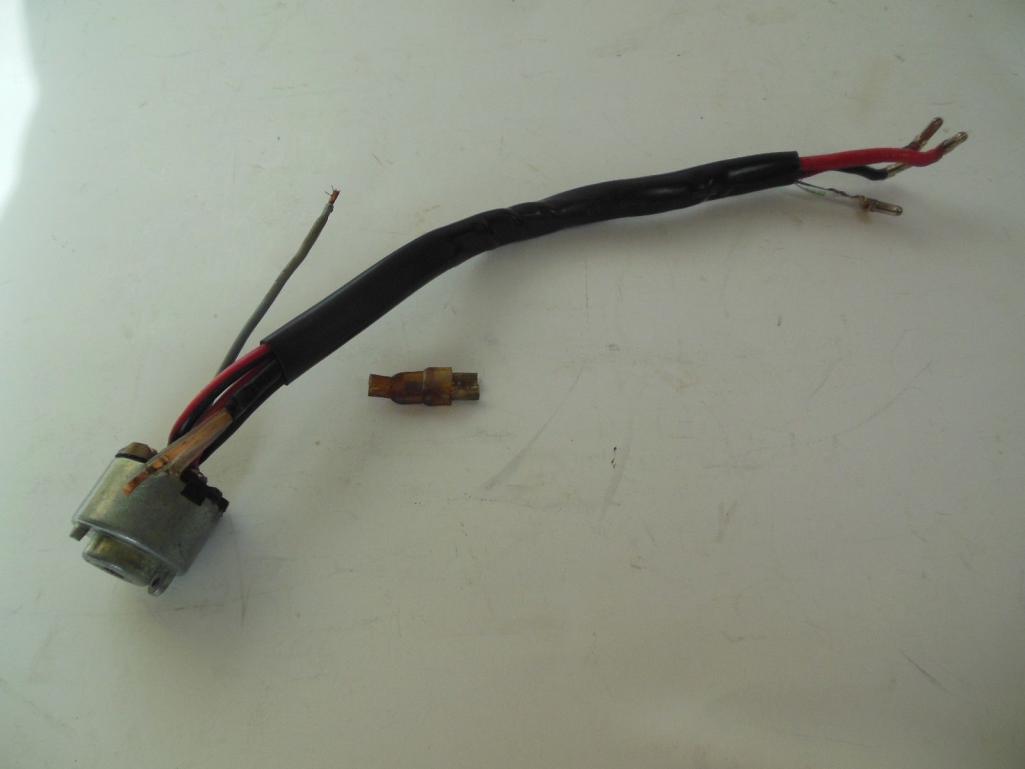
Posted by: 3d914 Feb 3 2016, 09:08 PM
The image below shows the switch (26) on the schematic.
Red wire (#30 at connection #12) goes to the fuse box (Fuse 11), the main light switch, and battery positive. This should be a thick wire.
White wire (#34) appears to go to the adjacent signal switch in the column.
Red/White wire (#35 at connection 13) also goes to the light switch.
Black wire (#15 at connection 8) goes to fuse box (Fuse 8) and to the rear relay board in the large connector at pin 8.
Yellow wire (#36 at connection 10) also goes to the rear relay board in the large connector at pin 1.
Doesn't look like you can do without any of these. Haynes has a good manual for the 914 with all the schematics. May prove helpful.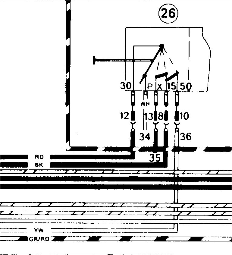
Posted by: pdlightning Feb 3 2016, 10:47 PM

The image below shows the switch (26) on the schematic.
Red wire (#30 at connection #12) goes to the fuse box (Fuse 11), the main light switch, and battery positive. This should be a thick wire.
White wire (#34) appears to go to the adjacent signal switch in the column.
Red/White wire (#35 at connection 13) also goes to the light switch.
Black wire (#15 at connection 8) goes to fuse box (Fuse 8) and to the rear relay board in the large connector at pin 8.
Yellow wire (#36 at connection 10) also goes to the rear relay board in the large connector at pin 1.
Doesn't look like you can do without any of these. Haynes has a good manual for the 914 with all the schematics. May prove helpful.
Does that mean the replacement switch doesn't have enough wires? All of the replacement switches I have seen for the 70-71 4 cyls have only four wires. The 6 cyls have a reg 911 multi pin replacement switch.
Posted by: McMark Feb 4 2016, 09:00 AM
The see-thru wire looks like a ground. I'd use an ohmmeter to confirm all the wire functions before I installed it.
Posted by: mark04usa Feb 4 2016, 12:04 PM
The see-thru wire looks like a ground. I'd use an ohmmeter to confirm all the wire functions before I installed it.
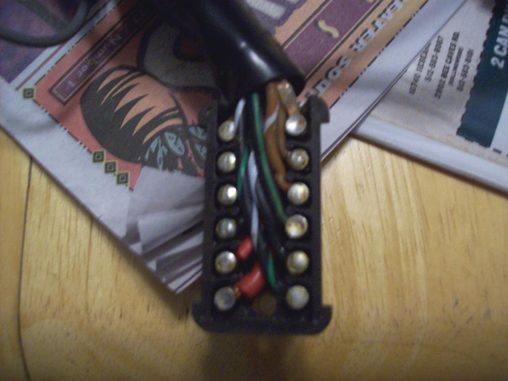
I replace the ignition swith on my '70 914 recently. You'll need to unsolder the connectors and reuse them to fit the wiring back into the connector as shown. Be sure to cut the wires to precise length needed. The copper "see-through" wire is a ground.
Posted by: radobard Feb 11 2016, 11:19 PM
Where does this ground wire connect within the ignition switch housing?
Roland
Posted by: McMark Feb 12 2016, 09:54 AM
According to the picture posted above, the clear grounding wire just soldered to the outside of the housing.
Posted by: porsche913b_sp Feb 26 2016, 06:28 PM
I would like to know also where the see thru ground terminates in the column/igntion or ?? 
Posted by: Jeff Bowlsby Feb 28 2016, 12:05 AM
That clear jacketed solid flat copper conductor goes up into the mechanical section of the keyed ignition lock mechanism, it is not part of the electrical ignition switch. I ohmed out the circuits and it appears to be the ground for the buzzer because it grounds at the first click of the key switch, is off otherwise.
Posted by: 914Mike Feb 28 2016, 12:49 PM
That clear jacketed solid flat copper conductor goes up into the mechanical section of the keyed ignition lock mechanism, it is not part of the electrical ignition switch. I ohmed out the circuits and it appears to be the ground for the buzzer because it grounds at the first click of the key switch, is off otherwise.
I seem to remember that wire was grounded by the key itself when it was inserted all the way on my '71, maybe that's different on '70?
Makes sense that the buzzer only sounds if the door is open with the key still in...
Posted by: mark04usa Feb 29 2016, 02:08 AM
That clear jacketed solid flat copper conductor goes up into the mechanical section of the keyed ignition lock mechanism, it is not part of the electrical ignition switch. I ohmed out the circuits and it appears to be the ground for the buzzer because it grounds at the first click of the key switch, is off otherwise.
 Yes, the end of the flat copper ground gets squashed in an interference fit between the tumbler body and the column housing. When it doesn't ground well, my warning buzzer doesn't work. I left it that way for years just to get rid of annoying buzzer
Posted by: Jeff Bowlsby Mar 2 2016, 11:47 AM

Attached thumbnail(s)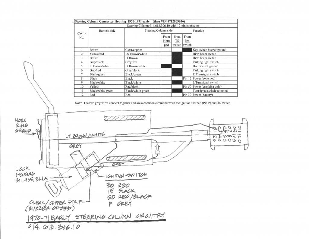
Posted by: porsche913b_sp Mar 2 2016, 09:06 PM
Wow that's great information. I appreciate it. Thank you Jeff.

 since it's still apart I might try to chase that buzzer wire in the column
Posted by: raynekat May 12 2017, 01:56 PM
Just to resurrect an old thread and question.
The new replacement ignition switches do not have the clear jacketed ground wire.
This wire is only used to activate a buzzer when you leave key in the car with the door open?
If I don't care about the buzzer, that cavity (no. 1) can be left empty on the ignition side of that connector?
Thx in advance....
Powered by Invision Power Board (http://www.invisionboard.com)
© Invision Power Services (http://www.invisionpower.com)