Printable Version of Topic
Click here to view this topic in its original format
914World.com _ 914World Garage _ Fuel pressure and spark but won't run
Posted by: Groosh Jun 5 2016, 01:24 PM
Hi. I recently bought a '74 1.8 and am looking for help to get it running. It has the original fuel injection and ran late last year according the previous owner.
Here's what I know after reading many posts in the forum and working on it. Thanks to everybody who contributes, I couldn't have gotten this far without your help.
- The dual relay is bad I believe. After wiring it all back up, there is power from the ignition to both the start wire and run wire but no power to the fuel pump. I'm jumping the pump currently to test
- All relays in the board work
- Fuel pressure gauge shows 35psi on startup. I didn't install this gauge but seems to work ok
- Will fire with starting fluid
I'm thinking I must be pretty close and suspect the car isn't getting fuel but the gauge shows pressure?
Posted by: The Cabinetmaker Jun 5 2016, 01:28 PM
An inline pressure gauge will show pressure in the system, but that doesn't mean fuel is getting past the injectors.
Posted by: Groosh Jun 5 2016, 01:30 PM

An inline pressure gauge will show pressure in the system, but that doesn't mean fuel is getting past the injectors.
Thanks. So if it firing on fluid the injectors are working but somehow I need to figure out if they are getting fuel. The fuel pressure gauge is off the right side rail. Any ideas on what to try next?
Posted by: r_towle Jun 5 2016, 01:35 PM
Stick a pencil in the round intake end of the air-fuel meter.
Open the flapper door
You use the pencil to hold the door open, not to run the car, just to test
Turn on key to run
Do you hear the fuel pump?
Posted by: Groosh Jun 5 2016, 01:42 PM
Stick a pencil in the round intake end of the air-fuel meter.
Open the flapper door
You use the pencil to hold the door open, not to run the car, just to test
Turn on key to run
Do you hear the fuel pump?
Can there be pressure in the fuel system but no fuel? Maybe the filter or something is clogged before the gauge?
- Fuel pump works
Posted by: timothy_nd28 Jun 5 2016, 01:59 PM
Rich's test is a good one, it's testing if your fuel pump turns on and it's also testing if part of the dual relay is working.
Posted by: jim_hoyland Jun 5 2016, 02:08 PM
And the 6 pin connector is plugged into the AFM ?
Posted by: Groosh Jun 5 2016, 02:10 PM
Rich's test is a good one, it's testing if your fuel pump turns on and it's also testing if part of the dual relay is working.
The relay isn't working as far as I know but I'm jumping the fuel pump right now. Power is getting to the relay properly from the ignition but not turning on the pump. Will that alter something else?
So if it fires under starting fluid, has fuel pressure but apparently no fuel, maybe it's as simple as a clogged filter?
Posted by: timothy_nd28 Jun 5 2016, 02:16 PM
Hi. I recently bought a '74 1.8 and am looking for help to get it running. It has the original fuel injection and ran late last year according the previous owner.
Here's what I know after reading many posts in the forum and working on it. Thanks to everybody who contributes, I couldn't have gotten this far without your help.
- The dual relay is bad I believe. After wiring it all back up, there is power from the ignition to both the start wire and run wire but no power to the fuel pump. I'm jumping the pump currently to test
- All relays in the board work
- Fuel pressure gauge shows 35psi on startup. I didn't install this gauge but seems to work ok
- Will fire with starting fluid
I'm thinking I must be pretty close and suspect the car isn't getting fuel but the gauge shows pressure?
This comment has me concerned, what was de-wired? The dual relay does many things, one being the fuel pump but more importantly it turns on the Ljet computer.
Posted by: emoze Jun 5 2016, 05:16 PM
NO - if it fires on start fluid but won't run
- the injectors are either stuck or not pulsing - put a NOID Light on the injector plugs to narrow it down
if it firing on fluid the injectors are working but somehow I need to figure out if they are getting fuel. The fuel pressure gauge is off the right side rail. Any ideas on what to try next?
Posted by: Groosh Jun 5 2016, 05:23 PM
Hi. I recently bought a '74 1.8 and am looking for help to get it running. It has the original fuel injection and ran late last year according the previous owner.
Here's what I know after reading many posts in the forum and working on it. Thanks to everybody who contributes, I couldn't have gotten this far without your help.
- The dual relay is bad I believe. After wiring it all back up, there is power from the ignition to both the start wire and run wire but no power to the fuel pump. I'm jumping the pump currently to test
- All relays in the board work
- Fuel pressure gauge shows 35psi on startup. I didn't install this gauge but seems to work ok
- Will fire with starting fluid
I'm thinking I must be pretty close and suspect the car isn't getting fuel but the gauge shows pressure?
This comment has me concerned, what was de-wired? The dual relay does many things, one being the fuel pump but more importantly it turns on the Ljet computer.
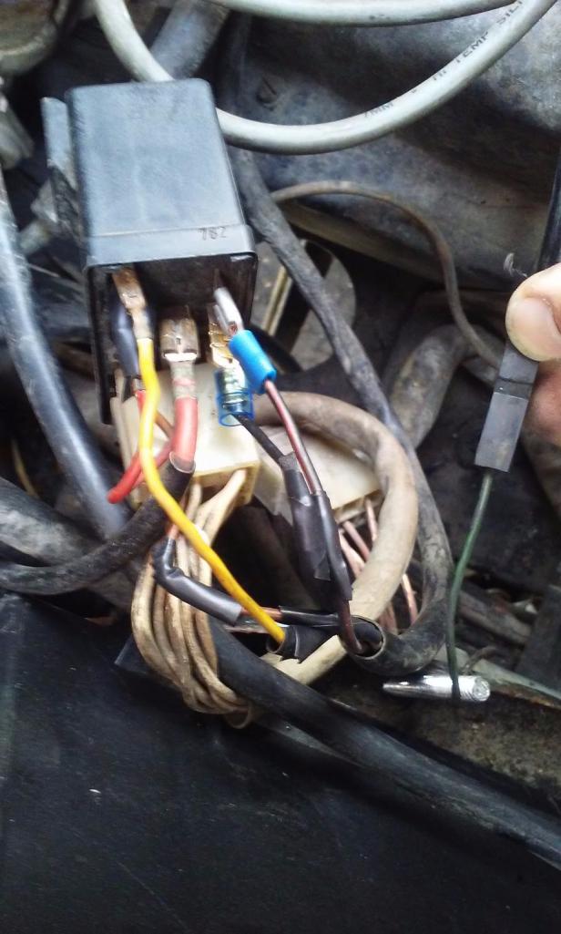
The owner pulled apart the dual relay - fuel pump/injector side - which I had to wire back together because he said there was a "fuel pump issue" which I think is the relay. Everything else seems to be intact relating to the engine and the other half of the dual relay. The lights, radio and gauges are another story.
Oh. There is one black with green stripe wire that is not connected. Not sure where that goes? Please don't judge the wire connectors. I'm just getting it together so it runs and will clean this up later.
Attached thumbnail(s)
Posted by: ejm Jun 5 2016, 05:44 PM
- Will fire with starting fluid
Oh. There is one black with green stripe wire that is not connected. Not sure where that goes?
The wire is for an oil temp gauge if your car has one. Did you drain the tank and put some fresh fuel in?
Posted by: timothy_nd28 Jun 5 2016, 06:24 PM
I'm not sure if I can see the jumper from 88Y to 88Z, other than that it looks wired correctly.
With the ignition set to on and the ECU connector unplugged, do you get 12vdc at pin 10 to ground?
What was the results with Rich's test with the pencil in the AFM?
Posted by: Twonicks001 Jun 5 2016, 07:34 PM
I know this sounds overly simplistic but it had me going for a week or so. Do you have 12v at the fuel pump plug? My plug was bad. When I cut it off and spliced in my own clips to the pump, I was in business. Just a thought.
Good luck.
Posted by: motorvated Jun 6 2016, 06:33 AM
If the injectors are not firing, you might want to confirm that the ground wire from the fuel injection harness is connected to a good clean spot on the engine block (not on the fan housing), and be sure the injector resistor pack is installed and the connector is clean. If it's there, carefully pull the connector apart a few times for a better connection. Injectors don't get any power without the resistor pack installed and therefore won't fire. Wires can break off of the resistor pack too, so be careful with it.
Posted by: Groosh Jun 9 2016, 12:45 PM
Stick a pencil in the round intake end of the air-fuel meter.
Open the flapper door
You use the pencil to hold the door open, not to run the car, just to test
Turn on key to run
Do you hear the fuel pump?
So I put a pencil in the door and did not hear the pump run. Not sure if I'm doing things right. I'm still jumping the fuel pump to run it but not getting injectors to fire.
Posted by: Groosh Jun 9 2016, 12:46 PM
If the injectors are not firing, you might want to confirm that the ground wire from the fuel injection harness is connected to a good clean spot on the engine block (not on the fan housing), and be sure the injector resistor pack is installed and the connector is clean. If it's there, carefully pull the connector apart a few times for a better connection. Injectors don't get any power without the resistor pack installed and therefore won't fire. Wires can break off of the resistor pack too, so be careful with it.
The ground looks clean and the resistor pack looks good. The wires are not frayed and took it apart several times to hopefully get a clean connection.
Posted by: Groosh Jun 9 2016, 12:48 PM
I'm not sure if I can see the jumper from 88Y to 88Z, other than that it looks wired correctly.
With the ignition set to on and the ECU connector unplugged, do you get 12vdc at pin 10 to ground?
What was the results with Rich's test with the pencil in the AFM?
The jump is there. I tried to unplug the ECU and test for 12vdc from any pin and did not seem to get any.
I also bought a new relay which came today. It didn't help. I did notice that the fuel ground from the relay is hot. I traced it to the motor where it is grounded and get a volts from it.
Posted by: r_towle Jun 9 2016, 12:53 PM
Without more accurate testing I would strongly suggest your AFM may need to be replaced, and your wiring needs to be redone properly.
Posted by: timothy_nd28 Jun 9 2016, 01:01 PM
Adding new parts just confounds the problem. Remove the fuel pump jumper and re-install the old dual relay.
When you tested for voltage on pin 10 of the ECU connector, was the ignition switch to on?
If so, let's do one thing before continuing with further tests. On the ignition coil, there should be a single wire on the (+) side terminal. Remove this wire, and tape it off. It's bad for the ignition coil and points when doing tests with the ignition key set for on, but the engine not running.
After the wire has been removed, we need to measure some voltages at the dual relay. With the meter set to DC, put the black lead on the negative battery post. Now with the red meter lead, probe pin 88z, then 88a and 88b. Report back what you see. This above test is done with the ignition key set to the "on or run" position.
Posted by: timothy_nd28 Jun 9 2016, 01:23 PM
Also if you don't already own these, run to RadioShack and pick this up
Posted by: Groosh Jun 10 2016, 01:05 PM
Adding new parts just confounds the problem. Remove the fuel pump jumper and re-install the old dual relay.
When you tested for voltage on pin 10 of the ECU connector, was the ignition switch to on?
If so, let's do one thing before continuing with further tests. On the ignition coil, there should be a single wire on the (+) side terminal. Remove this wire, and tape it off. It's bad for the ignition coil and points when doing tests with the ignition key set for on, but the engine not running.
After the wire has been removed, we need to measure some voltages at the dual relay. With the meter set to DC, put the black lead on the negative battery post. Now with the red meter lead, probe pin 88z, then 88a and 88b. Report back what you see. This above test is done with the ignition key set to the "on or run" position.
Ok. I tried pin 10 again with the switch on but did not read any volts.
After taping off the positive lead to the coil, I tested the following with the ignition switch on:
88z - 12 volts
88a - nothing
88b - nothing
Posted by: timothy_nd28 Jun 10 2016, 04:05 PM
Okay, use one of the jumper wires you just bought from Radio Shack and jump pin 86C on the dual relay to the positive battery terminal. Then recheck for voltages as I described in the earlier step.
Posted by: Groosh Jun 11 2016, 06:53 AM
Okay, use one of the jumper wires you just bought from Radio Shack and jump pin 86C on the dual relay to the positive battery terminal. Then recheck for voltages as I described in the earlier step.
86c was already getting proper volts from the ignition switch in the "on" position so I didn't jump it. However I still get no other readings on 88a or 88b.
Posted by: timothy_nd28 Jun 11 2016, 07:15 AM
Okay, jump pin 85 at the dual relay to the negative battery post. Redo same test as above.
Posted by: Groosh Jun 11 2016, 10:08 AM
Okay, jump pin 85 at the dual relay to the negative battery post. Redo same test as above.
Heard the relay click for the first time and got 12 volts on 88a and 88b.
Posted by: timothy_nd28 Jun 11 2016, 11:54 AM
What about pin 10 at the ECU?
Posted by: Groosh Jun 11 2016, 12:14 PM
What about pin 10 at the ECU?
I'm not getting any power off of the ECU at pin 10.
Posted by: timothy_nd28 Jun 11 2016, 01:30 PM
We need to make sure that you are indeed probing pin 10 of the ECU connector. So, put your meter on a low resistance setting. Then put one meter lead on the negative (-) terminal of the ignition coil, put the other lead on what you think is pin 1 of the ECU connector, you should get 0 ohms
Posted by: Groosh Jun 11 2016, 02:02 PM
We need to make sure that you are indeed probing pin 10 of the ECU connector. So, put your meter on a low resistance setting. Then put one meter lead on the negative (-) terminal of the ignition coil, put the other lead on what you think is pin 1 of the ECU connector, you should get 0 ohms
Well, I did get 0 ohms. As far as me doing it right? I hope so.
Posted by: timothy_nd28 Jun 11 2016, 02:22 PM
We might as well check some other wires, I'm starting to doubt your wiring harness.
Key on, wire still off (and taped) the ignition coil, jumper wire still on pin 85 (dual relay) to negative battery terminal, meter set for DC volts, put one meter lead on the negative battery post. Now, make sure you still have 12vdc on pins 88a and 88b of the dual relay, if so you can continue.
Leave one meter lead on the negative battery post. Put the other meter lead on pin 14 of the ECU connector, you should get 12vdc. If so, move the meter lead from pin 14 and place it on pin 15, again you should see 12vdc. Move the meter lead from pin 15, and place it on pin 32, you should see 12vdc. Finally, move the meter lead from pin 32 and move it to pin 33, you should see 12vdc.
This tests the continuity of the wiring to the fuel injector, continuity of the injector itself, continuity of the wires leaving the injector to the resistor pack, continuity of the resistors. This is a good test, kinda checks everything.
After all that, put one meter lead on the positive battery post. With the other meter lead, probe pins: 5,16, and 17 on the ecu connector. You should have 12volts on each pin.
If all that passes, recheck pin 10 on the ecu connector for 12vdc. Pin 10 is a very important pin. This pin supplies power to the ECU, no power to this pin will keep the computer off.
Posted by: Groosh Jun 12 2016, 11:24 AM
We might as well check some other wires, I'm starting to doubt your wiring harness.
Key on, wire still off (and taped) the ignition coil, jumper wire still on pin 85 (dual relay) to negative battery terminal, meter set for DC volts, put one meter lead on the negative battery post. Now, make sure you still have 12vdc on pins 88a and 88b of the dual relay, if so you can continue.
Leave one meter lead on the negative battery post. Put the other meter lead on pin 14 of the ECU connector, you should get 12vdc. If so, move the meter lead from pin 14 and place it on pin 15, again you should see 12vdc. Move the meter lead from pin 15, and place it on pin 32, you should see 12vdc. Finally, move the meter lead from pin 32 and move it to pin 33, you should see 12vdc.
This tests the continuity of the wiring to the fuel injector, continuity of the injector itself, continuity of the wires leaving the injector to the resistor pack, continuity of the resistors. This is a good test, kinda checks everything.
After all that, put one meter lead on the positive battery post. With the other meter lead, probe pins: 5,16, and 17 on the ecu connector. You should have 12volts on each pin.
If all that passes, recheck pin 10 on the ecu connector for 12vdc. Pin 10 is a very important pin. This pin supplies power to the ECU, no power to this pin will keep the computer off.
Shoot. I was doing it wrong before and now have myself straightened out. Here is where I'm getting 12vdc with the key "on"
- 10 pin
- 15 pin
- 32 pin
- 5, 16, 17
Not getting volts on:
- 14, 33
Posted by: timothy_nd28 Jun 12 2016, 07:25 PM
Pin 14 and 33 are two of the four injectors. Disconnect the resistor pack and post a picture
Posted by: timothy_nd28 Jun 12 2016, 07:43 PM
The resistor pack should look similar to this: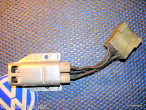
Once you disconnect the connector to this device, set your meter for resistance and put one meter lead at the center pin (on the connector leading to the resistor pack). Probe the outside pins with the other meter lead. You should get a pretty low resistance on those four pins.
These wires are frail and tend to break. It would be nice to rule this out before diving into a more complicated test procedure.
Posted by: Groosh Jun 13 2016, 07:02 AM
The resistor pack should look similar to this:
Once you disconnect the connector to this device, set your meter for resistance and put one meter lead at the center pin (on the connector leading to the resistor pack). Probe the outside pins with the other meter lead. You should get a pretty low resistance on those four pins.
These wires are frail and tend to break. It would be nice to rule this out before diving into a more complicated test procedure.
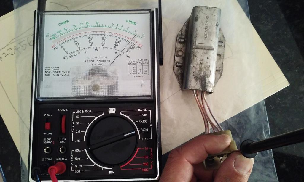
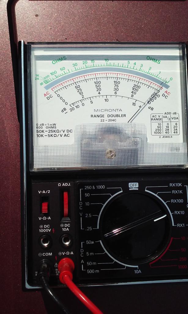
The wires look good. The resistance is even across all four pins. Yes, I kick it old school with my father's old meter.
Attached thumbnail(s)
Posted by: timothy_nd28 Jun 13 2016, 10:13 AM
Old meters like that are awesome! Go ahead and reinstall the resistor pack, then try re-seating each fuel injector connector. So, remove the 2 pin electrical connector from a fuel injector, then push it back on. Do this 13 times for each fuel injectors' connector. After all this is done, and assuming that jumper is still on pin 85 of the dual relay and the ignition key is on,,put one meter lead on the negative battery post. With the other meter lead, probe pins 14,15,32,33 to see if they have 12volts, more importantly does pin 14 and 33 now have voltage after reseating the fuel injector connectors?
If the above instructions fail to remedy pins 14 and 33 then lets continue.
We need to know what injectors correlate to pins 14 and 33. To find this out, we can use the injectors that do work, pins 15 and 32. Put your meter lead on pin 15 and with the same test conditions as the paragraph above, you should get 12volts. Start by unplugging one fuel injector at a time while watching your meter. If the 12volts drops out when unplugging, then that injector matches up with pin 15. If 12volts is still present after unplugging one fuel injector, simply plug that connector back in and move onto the next fuel injector connector. Rinse and repeat till you find that one injector that makes pin 15 go dead. Repeat the same test but put the meter lead in pin 32, find that other good injector.
Once you find the two good injectors, we now know the two problem injectors.
With the offending fuel injectors, go ahead and remove the connectors for those two. It will be hard to probe these pins with your meter, you may need to fashion a paperclip at the end of your meter lead.
Ok, with the ignition switch set to on and your jumper still on the dual relay, put one meter lead on the negative battery post. We are measuring for 12volts. Probe both pins of each injector harness connector. Of the two pins, only one will show 12volts while the other pin will read nothing, do this for both bad injectors.
Posted by: Groosh Jun 20 2016, 07:17 AM
Old meters like that are awesome! Go ahead and reinstall the resistor pack, then try re-seating each fuel injector connector. So, remove the 2 pin electrical connector from a fuel injector, then push it back on. Do this 13 times for each fuel injectors' connector. After all this is done, and assuming that jumper is still on pin 85 of the dual relay and the ignition key is on,,put one meter lead on the negative battery post. With the other meter lead, probe pins 14,15,32,33 to see if they have 12volts, more importantly does pin 14 and 33 now have voltage after reseating the fuel injector connectors?
If the above instructions fail to remedy pins 14 and 33 then lets continue.
We need to know what injectors correlate to pins 14 and 33. To find this out, we can use the injectors that do work, pins 15 and 32. Put your meter lead on pin 15 and with the same test conditions as the paragraph above, you should get 12volts. Start by unplugging one fuel injector at a time while watching your meter. If the 12volts drops out when unplugging, then that injector matches up with pin 15. If 12volts is still present after unplugging one fuel injector, simply plug that connector back in and move onto the next fuel injector connector. Rinse and repeat till you find that one injector that makes pin 15 go dead. Repeat the same test but put the meter lead in pin 32, find that other good injector.
Once you find the two good injectors, we now know the two problem injectors.
With the offending fuel injectors, go ahead and remove the connectors for those two. It will be hard to probe these pins with your meter, you may need to fashion a paperclip at the end of your meter lead.
Ok, with the ignition switch set to on and your jumper still on the dual relay, put one meter lead on the negative battery post. We are measuring for 12volts. Probe both pins of each injector harness connector. Of the two pins, only one will show 12volts while the other pin will read nothing, do this for both bad injectors.
Well go figure. After the car sat for almost a week things tested out differently. I did the pull reset 13x on the fuel injectors:
- 32 is cylinder 2 and gets volts at the 32 pin
- 33 is cylinder 3 and gets volts at the 33 pin
- 14 no volts at pin - injector harness gets 12 volts
- 15 no volts at pin - injector harness gets 12 volts
Posted by: timothy_nd28 Jun 20 2016, 08:18 AM
For injectors 4 and 1, is this 12volts at the fuel injector connector? If so, test the resistance across the two pins on the fuel injector itself.
Posted by: Groosh Jun 20 2016, 09:13 AM
For injectors 4 and 1, is this 12volts at the fuel injector connector? If so, test the resistance across the two pins on the fuel injector itself.
Yes. Injectors 1 and 4 get 12 volts at the injector connector.
The resistance across all four injectos tests even.
Attached thumbnail(s)
Posted by: timothy_nd28 Jun 20 2016, 09:54 AM
Since the injectors all have continuity, the problem lies in a short wire run from the injector's connector to the ECU connector. I highlighted a red box that illustrates the problem area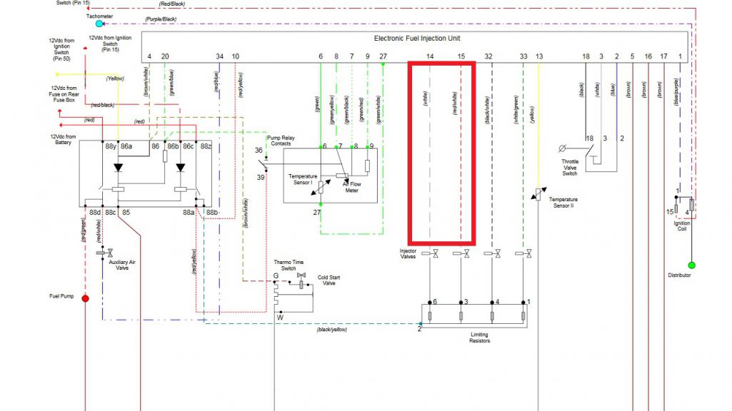
Since you already tested the FI connector of the two failed injectors, and confirmed that you have 12 volts sitting at one of the two pins, confirms that the dual relay is sending voltage thru the resistor pack and is making its way to the fuel injector. Missing voltage at the ECU pins 14 and 15 tells me that there is a break in a wire or a bad connection at one of the connectors.
You can remove the fuel injector connector and reconfirm that you do indeed have 12 volts present on one of the two pins. The other dead pin, you can check the resistance of that pin to the ECU connector, which will be either pin 14 or 15. You should read 0 ohms, but since you are not getting voltage on pins 14 or 15, you may read a high resistance. I bet if you were to jiggle the harness while measuring resistance, you may see things change with your meter.
Be extra observant at the two failed injectors, look at the wires and pins at the injector connector. Same thing for pins 14 and 15 at the ECU connector.
After all that, you have 3 options.
Send your injection harness off to Jeff Bowlsby for repair, or buy a known good used one, or if you are up for it; get a razor blade and split the outer casing of the injection harness and find pin 14/15 wires and repair it yourself.
Posted by: Groosh Jun 23 2016, 08:17 AM
Since the injectors all have continuity, the problem lies in a short wire run from the injector's connector to the ECU connector. I highlighted a red box that illustrates the problem area
Since you already tested the FI connector of the two failed injectors, and confirmed that you have 12 volts sitting at one of the two pins, confirms that the dual relay is sending voltage thru the resistor pack and is making its way to the fuel injector. Missing voltage at the ECU pins 14 and 15 tells me that there is a break in a wire or a bad connection at one of the connectors.
You can remove the fuel injector connector and reconfirm that you do indeed have 12 volts present on one of the two pins. The other dead pin, you can check the resistance of that pin to the ECU connector, which will be either pin 14 or 15. You should read 0 ohms, but since you are not getting voltage on pins 14 or 15, you may read a high resistance. I bet if you were to jiggle the harness while measuring resistance, you may see things change with your meter.
Be extra observant at the two failed injectors, look at the wires and pins at the injector connector. Same thing for pins 14 and 15 at the ECU connector.
After all that, you have 3 options.
Send your injection harness off to Jeff Bowlsby for repair, or buy a known good used one, or if you are up for it; get a razor blade and split the outer casing of the injection harness and find pin 14/15 wires and repair it yourself.
Hmmmm... I have the injector harness off. I notice a pin on one injector pushed in but all the injector wiring tests good when I connect from the injector plug back to the ECU connector. I also test good from the restistor pack plug to the injector plug.
That being said, there are bad wires. But I'm not sure what to make of it all before I go slicing and dicing.
Posted by: timothy_nd28 Jun 23 2016, 03:38 PM
So you have 12volts on pins 14,15,32&33?
Posted by: Groosh Oct 5 2016, 05:26 PM
Thanks to all of Tim's work, I have a repaired fuel injector harness back in the car. Thanks Tim!
The last we left it, I was at the following trying to test the ground.
Okay, jump pin 85 at the dual relay to the negative battery post. Redo same test as above.
Heard the relay click for the first time and got 12 volts on 88a and 88b.
Posted by: Groosh Oct 18 2016, 02:35 PM
Well, I started back at the beginning of our testing.
After taping off the positive lead to the coil, I tested as follows:
- Ignition switch on
- Negative lead from multi meter on battery
- Positive lead touching the following:
88z - 12 volts
88a - 12 volts
88b - 12 volts
88d - will run fuel pump with 12 volts jump wire from positive terminal
86c - will get 12 volts with jump wire from negative battery terminal
Posted by: timothy_nd28 Oct 18 2016, 03:59 PM
Try deflecting the air flow meter flap with the ignition switch on, does the fuel pump engage?
Also, measure pins 14,15,32 and 33 by having the ignition switch on, and the meter set for DC volts. Put one meter lead on the negative battery post, and the other meter lead in the ECU sockets 14,15,32,33.
Posted by: Groosh Oct 19 2016, 02:02 PM
Try deflecting the air flow meter flap with the ignition switch on, does the fuel pump engage?
Also, measure pins 14,15,32 and 33 by having the ignition switch on, and the meter set for DC volts. Put one meter lead on the negative battery post, and the other meter lead in the ECU sockets 14,15,32,33.
Yes, fuel pump engages with deflected air flow meter and key switched on.
With the meter set to DC 50 and key on, I'm reading 12 volts at ECU sockets 14,15,32,33.
Posted by: timothy_nd28 Oct 19 2016, 07:58 PM
Cool, much better results than last time.
Posted by: timothy_nd28 Oct 19 2016, 10:48 PM
Car is almost ready to run. I would do one more test to verify the injectors do still work and are spraying fuel. Unclamp all injectors from the manifold, leave the fuel lines attached and electrical connectors plugged in. Find a way to put mason jars under each fuel injector. Set the ignition switch to on and temporarily open the airflow meter flap or jamb a screwdriver inside to keep the flap open.
With a wire, attach one side to the negative battery post. Take the other side of this wire and probe pins 14,15,32,33 at the ecu connector. Watch the fuel injectors as you do this. It should be a mist of fuel spraying, make sure all spray patterns look the same.
Next, take your voltmeter and set it for resistance. Probe pin 13 at the ecu connector while the other lead is on the negative battery post.
Finally, reassemble and prepare the car to start. Make sure you reattach the power wire back on the ignition coil and you remove the screw driver from the airflow meter.
Posted by: Groosh Oct 22 2016, 07:35 AM
Car is almost ready to run. I would do one more test to verify the injectors do still work and are spraying fuel. Unclamp all injectors from the manifold, leave the fuel lines attached and electrical connectors plugged in. Find a way to put mason jars under each fuel injector. Set the ignition switch to on and temporarily open the airflow meter flap or jamb a screwdriver inside to keep the flap open.
With a wire, attach one side to the negative battery post. Take the other side of this wire and probe pins 14,15,32,33 at the ecu connector. Watch the fuel injectors as you do this. It should be a mist of fuel spraying, make sure all spray patterns look the same.
Next, take your voltmeter and set it for resistance. Probe pin 13 at the ecu connector while the other lead is on the negative battery post.
Finally, reassemble and prepare the car to start. Make sure you reattach the power wire back on the ignition coil and you remove the screw driver from the airflow meter.
Well, I'm not seeing any fuel come out at all. I first tested this by cranking the car over with little jars under each injector. Only cylinder #2 had a little fuel mist and then it didn't do it again. I tried again by jumping the negative battery post and probing the pins and did not hear or see any sign of fuel coming from the injectors. The fuel pump was running.
Posted by: timothy_nd28 Oct 22 2016, 10:09 AM
Ok, I'm very glad that you did this test. First, we must rule out the simple, do you have fuel? What is the fuel pressure at the fuel rail?
A few tests ago you measured 12 volts from pins 14,15,32 and 33 to battery ground. This test proves that you have continuity from the ECU connector thru the wiring harness, the fuel injector itself has continuity, the wiring harness to the dropping resistors has continuity, and finally, the harness to the dual relay has continuity. All of this is a very good thing.
Even though each fuel injector show's continuity, this does not prove that they will work. Mechanically, these injectors could be seized or plugged full of  . Let's do one more test just to prove that these injectors are working electrically.
These injectors are low impedance, I'm pretty sure they are around 2.5 ohms (correct me if I'm wrong). You also have a 6 ohm dropping resistor in series of each fuel injector (resistor pack). Using a simple equation I=E/R, we can solve for current on each injector circuit. Total resistance is around 8.5 ohms, voltage is 13, so we should see something around 1.5 amps.
Many meters will measure amperage's for DC circuits. The meter will usually have something that will say DC A, and they typically measure up to 10 amps. Make sure you don't have your meter set to DC milliamps, as this will blow the meter's internal fuse. Make sure the red meter lead is plugged into the correct port on the meter, DC amp setting usually has its own port.
Now, same test as before. Remove the power wire from the ignition coil, set the ignition switch to on, temporarily deflect the air flow meter flap or jump pin 88d at the dual relay to the positive battery post. Next, insert the red meter lead into socket 14 of the ECU connector, while the black meter lead is touching the negative battery post. You should hear a click at the fuel injector, should also see fuel spraying too. As all of this is going on, observe what your meter is saying, should be somewhere of 1.5 amps.
Repeat this for pins 15, 32 and 33.
If you are seeing 1.5 amps at each injector, and you have verified fuel pressure at the fuel rail, then you send off your injectors to WitchHunters for cleaning.
Posted by: Groosh Oct 22 2016, 11:53 AM
Ok, I'm very glad that you did this test. First, we must rule out the simple, do you have fuel? What is the fuel pressure at the fuel rail?
A few tests ago you measured 12 volts from pins 14,15,32 and 33 to battery ground. This test proves that you have continuity from the ECU connector thru the wiring harness, the fuel injector itself has continuity, the wiring harness to the dropping resistors has continuity, and finally, the harness to the dual relay has continuity. All of this is a very good thing.
Even though each fuel injector show's continuity, this does not prove that they will work. Mechanically, these injectors could be seized or plugged full of
. Let's do one more test just to prove that these injectors are working electrically.These injectors are low impedance, I'm pretty sure they are around 2.5 ohms (correct me if I'm wrong). You also have a 6 ohm dropping resistor in series of each fuel injector (resistor pack). Using a simple equation I=E/R, we can solve for current on each injector circuit. Total resistance is around 8.5 ohms, voltage is 13, so we should see something around 1.5 amps.
Many meters will measure amperage's for DC circuits. The meter will usually have something that will say DC A, and they typically measure up to 10 amps. Make sure you don't have your meter set to DC milliamps, as this will blow the meter's internal fuse. Make sure the red meter lead is plugged into the correct port on the meter, DC amp setting usually has its own port.
Now, same test as before. Remove the power wire from the ignition coil, set the ignition switch to on, temporarily deflect the air flow meter flap or jump pin 88d at the dual relay to the positive battery post. Next, insert the red meter lead into socket 14 of the ECU connector, while the black meter lead is touching the negative battery post. You should hear a click at the fuel injector, should also see fuel spraying too. As all of this is going on, observe what your meter is saying, should be somewhere of 1.5 amps.
Repeat this for pins 15, 32 and 33.
If you are seeing 1.5 amps at each injector, and you have verified fuel pressure at the fuel rail, then you send off your injectors to WitchHunters for cleaning.
There is a fuel pressure meter on the rail. It reads about 50 psi but I have no idea if it is accurate. It does go up and down but I have never seen it settle at zero.
I tested all the injectors as described and they all fire a beautiful stream of fuel with about 1.5 amps on the meter set to DC A 10A.
Posted by: timothy_nd28 Oct 22 2016, 04:18 PM
Cool, not sure what your issue was with the previous test. Button the injectors back up and verify you still have spark. Try starting the car
Posted by: Groosh Oct 23 2016, 12:09 PM
Cool, not sure what your issue was with the previous test. Button the injectors back up and verify you still have spark. Try starting the car
I think we are missing something. The injectors do not fire when plugged into the ECU. They only fire when we jumped them. Could my ECU be bad? I tried pulling an injector and no fuel comes out when everything is put together. Additionally, I don't think I have spark anymore. The car did run on starter fluid in the being. But now it doesn't and looking for spark from a pulled plug reveals no spark.
Posted by: timothy_nd28 Oct 23 2016, 12:34 PM
The ECU uses the spark signal to fire the injectors. When doing the previous tests, I had you remove the power wire off the ignition coil. This was done to protect either your ignition points or your pointless module. It's bad to leave the ignition on with the car not running, as it will ruin the points.
We need to address your no spark condition. Do you have mechanical points inside the distributor or is it a electronic module?
Posted by: Groosh Oct 23 2016, 12:37 PM
The ECU uses the spark signal to fire the injectors. When doing the previous tests, I had you remove the power wire off the ignition coil. This was done to protect either your ignition points or your pointless module. It's bad to leave the ignition on with the car not running, as it will ruin the points.
We need to address your no spark condition. Do you have mechanical points inside the distributor or is it a electronic module?
I love how much you know Tim! The points are mechanical.
Posted by: timothy_nd28 Oct 23 2016, 12:39 PM
Verify you do have 12 volts present at the positive terminal of the ignition coil when the ignition switch is set to on. Measure this by probing the + terminal of the ignition coil and probing the negative battery post
Posted by: Groosh Oct 23 2016, 12:44 PM
Verify you do have 12 volts present at the positive terminal of the ignition coil when the ignition switch is set to on. Measure this by probing the + terminal of the ignition coil and probing the negative battery post
We have 12 volts at the coil.
Posted by: timothy_nd28 Oct 23 2016, 12:47 PM
Remove the distributor cap and rotor, and manually spring open the points while trying to take a picture. Post the picture if you can, I'm wondering if the points are burnt
Posted by: Groosh Oct 23 2016, 03:08 PM
Remove the distributor cap and rotor, and manually spring open the points while trying to take a picture. Post the picture if you can, I'm wondering if the points are burnt
Attached thumbnail(s)

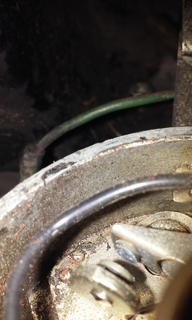
Posted by: timothy_nd28 Oct 23 2016, 03:11 PM
Yah, time to replace them.
Posted by: Groosh Oct 23 2016, 03:50 PM
Yah, time to replace them.
Happened to have a set at home. So I replaced and set the gap. I tried turning it over but still no love.
Posted by: timothy_nd28 Oct 23 2016, 06:12 PM
On the ignition coil, you should have 3 wires on the negative terminal and one wire on the positive terminal. After confirming that, remove all wires from the ignition coil and check the resistance between the positive and negative terminal of the ignition coil. Next, leave one meter lead probed to the negative terminal and probe the other meter lead to the spark plug socket of the ignition coil.
Posted by: Groosh Oct 24 2016, 03:05 PM
On the ignition coil, you should have 3 wires on the negative terminal and one wire on the positive terminal. After confirming that, remove all wires from the ignition coil and check the resistance between the positive and negative terminal of the ignition coil. Next, leave one meter lead probed to the negative terminal and probe the other meter lead to the spark plug socket of the ignition coil.
Yes, three wires on the negative. The postive has two wires tied together on it.
Probed the coil negative and positive and got 0 ohms resistance.
Probed the negative and positive at the spark plug socket and got 100 ohms resistance with meter set at RX100.
Posted by: timothy_nd28 Oct 24 2016, 04:58 PM
Just to make sure, did you pull all the wires off before testing? Positive to negative terminals should be around 4 ohms. Spark plug terminal to either terminal should be around 10,000 ohms.
Posted by: Groosh Oct 24 2016, 05:12 PM
Just to make sure, did you pull all the wires off before testing? Positive to negative terminals should be around 4 ohms. Spark plug terminal to either terminal should be around 10,000 ohms.
Yes, the wires were pulled. However I retested. This time I used a digital meter and found 4 ohms and about 9,470 ohms from the spark plug terminal.
Posted by: timothy_nd28 Oct 24 2016, 08:07 PM
That indicates that the coil is good. So, you have 12 volts on the + ignition coil terminal when the key is on, and a new set of points, but no spark.
Sounds like a grounding issue. Check the transmission ground strap
Posted by: timothy_nd28 Oct 24 2016, 10:55 PM
After checking the ground strap, take your voltmeter and check the resistance between the negative battery post and the thing I have circled in red, you should have 0 ohms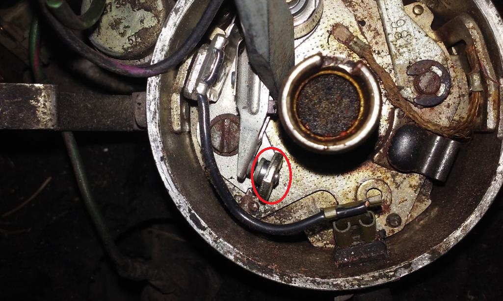
Posted by: Groosh Oct 25 2016, 02:00 PM
After checking the ground strap, take your voltmeter and check the resistance between the negative battery post and the thing I have circled in red, you should have 0 ohms
The ground strap from tranny to car looks good. Quite clean. There is also an extra ground cable from the negative battery terminal to the transmission.
The volt meter at the points think circled in red reads 0 ohms.
Posted by: timothy_nd28 Oct 25 2016, 02:17 PM
Reattach wires to the ignition coil. Turn the engine so that the ignition points are in the closed position. Check the resistance from the negative terminal of the ignition coil to the negative battery post. You should again see 0 ohms.
If you see 0 ohms, switch the meter to measure DC volts. Briefly turn the key to on and measure the voltage between the + and - terminals of the ignition coil. You should see 12 volts. Turn off the ignition as soon as you get your measurement.
Posted by: Groosh Oct 25 2016, 02:48 PM
Reattach wires to the ignition coil. Turn the engine so that the ignition points are in the closed position. Check the resistance from the negative terminal of the ignition coil to the negative battery post. You should again see 0 ohms.
If you see 0 ohms, switch the meter to measure DC volts. Briefly turn the key to on and measure the voltage between the + and - terminals of the ignition coil. You should see 12 volts. Turn off the ignition as soon as you get your measurement.
On this, my ohms meter did not go to 0.
I tried this measure too and did not get 12 volts. I did get any volts reading.
The key is off.
Posted by: timothy_nd28 Oct 25 2016, 02:52 PM
Silly question, but are the points in the closed position (touching each other) when you measured?
Posted by: Groosh Oct 25 2016, 03:24 PM
Silly question, but are the points in the closed position (touching each other) when you measured?
Yes. Were they supposed to be?
Posted by: timothy_nd28 Oct 25 2016, 04:10 PM
Yes. Now check the resistance between the negative terminal of the ignition coil to the points that I circled in red.
Posted by: Groosh Oct 25 2016, 04:32 PM
Yes. Now check the resistance between the negative terminal of the ignition coil to the points that I circled in red.
Key off, points closed. 0 ohms.
I noticed I kicked off a wire accidentally from the negative coil. I redid the test of resistance from negative coil to negative battery and got 0 ohms.
I tried the test from neg coil to pos coil for DC V and did not get anything. I think...
Posted by: timothy_nd28 Oct 25 2016, 04:57 PM
That's fine, thanks for telling me. Repeat the test from post# 56.
You have a solid ground at the negative terminal at the ignition coil, and if the results from post 56 gives you a green light, by definition you should have 12 volts between the positive and negative terminal at the ignition coil.
Posted by: Groosh Oct 25 2016, 05:01 PM
That's fine, thanks for telling me. Repeat the test from post# 56.
You have a solid ground at the negative terminal at the ignition coil, and if the results from post 56 gives you a green light, by definition you should have 12 volts between the positive and negative terminal at the ignition coil.
Yes. There are 12 volts at the positive coil metered to negative battery terminal.
Posted by: timothy_nd28 Oct 25 2016, 06:19 PM
Redo the test from the 2nd paragraph from post #69
Posted by: Groosh Oct 26 2016, 04:29 PM
So I've been working with Tim and he has been absolutely invaluable in helping me to diagnose and repair this wiring train wreck. Thank you to Tim and the 914World forum!
To help close the loop for others reading this post we, and by we I mean Tim, finally figured out that the condensor was shorting out. By cutting the wire to it we returned spark to the engine and it fired. The engine doesn't quite run but we are getting closer.
Posted by: Frankvw Oct 26 2016, 11:18 PM
That is good to hear. Thanks for the update. Interesting post for sure!
good luck with the final steps and keep us updated. I understand the issue is a pita for you, but by posting this others learn from it.
thanks Groosh and Tim.
Posted by: Groosh Feb 24 2017, 11:17 AM
Since it's 60 degrees in Michigan, I've attempted some updating on the car. I went to electronic ignition by Hot Spark and the car fired up. But as I was adjusting the timing and revving it, the car died.
It looks like the fuel pump stopped working. There was no pressure to the rail when I cranked. But then I tried to jumped the relay to get the fuel pump going and still the car doesn't run.
Harumph. I thought I had this thing ready.
Posted by: Groosh Mar 24 2017, 12:32 PM
Another warm day and another attempt. This time it is fixed!
It turns out the ground wire from the dual relay was attached to the fan shroud as pictured. This is a poor ground. I moved it over to the three prong engine ground (on the advice of Tim) and it fired right up. I drove it around the block after bleeding the brakes and it runs. 
Attached thumbnail(s)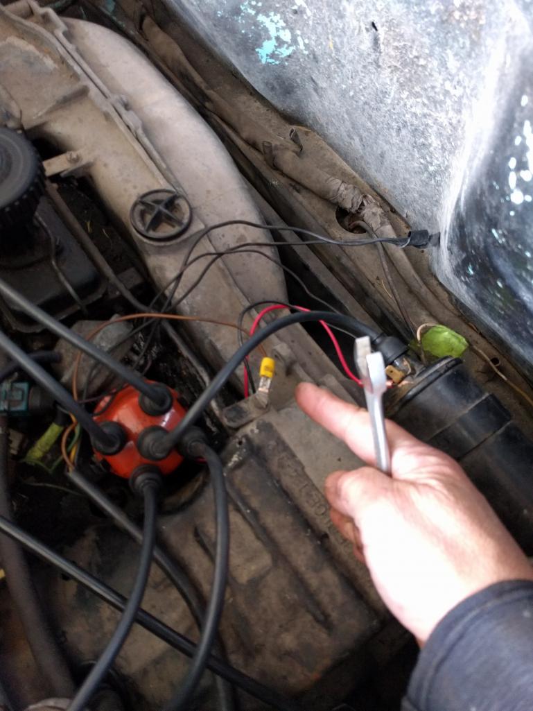
Posted by: mark04usa Mar 24 2017, 01:30 PM
 Glad to hear that you've had sucess. Thank you for posting the fix.
Posted by: timothy_nd28 Mar 24 2017, 02:13 PM
I love happy endings. It's been awhile since you worked on this, I had to re-read what was done. I'm still amazed you had a shorted condenser on the dizzy.
Powered by Invision Power Board (http://www.invisionboard.com)
© Invision Power Services (http://www.invisionpower.com)