Printable Version of Topic
Click here to view this topic in its original format
914World.com _ 914World Garage _ Minor Relay Plate Mods
Posted by: GregAmy Aug 20 2016, 09:26 AM
So I got hit by a dreaded http://www.914world.com/bbs2/index.php?showtopic=291477&hl= a couple weeks ago, eventually traced down to either a bad relay or bad relay board. Yay. Everything seemed to check out so I nailed it down to a possible bad relay board.
I'm seeing a lot of posts about relay board these days. Fortunately it seems there's a lot of them hanging out in garages, but unfortunately no one is apparently rebuilding them. Pelican shows to have http://www.pelicanparts.com/catalog/SuperCat/0978/POR_0978_ELSWCH_pg1.htm#item2, and one of our own here has a http://www.914world.com/bbs2/index.php?showtopic=259295&hl=, but it's not really in production and his last price was $500 (any way we can get that built in China to get the price down...?)
So at this point it looks like the community is burning through its good spares with no reasonable re-supply in sight.
In conversations with Chris Foley on this subject, he pointed out to me that these things tend to fail due to overheating, the packing underneath failing and cracking, water getting inside, corrosion, and even soldered joints coming apart. I do notice that my non-solid-state voltage regulator gets damned hot, and I see photos here of failure in that area. Plus, Chris said another area of failure is heat under the fuses that are on the plate.
VW had a problem with their fuse boards in the mid- to late-70s. When they went to fuel injection they mounted the fuel pump relay on the board itself. Problem was, there was so much current going through that board - and they may have used wiring that was slightly under-rated for that current - that it was melting the plastic relay board and causing failures. There was a big campaign (don't recall if it was a TSB or a recall) to remove the fuel pump relays from that board and mount them off to the side.
In light of that, after getting a good replacement from Chris I decided to make some minor adjustments to the board to try to stave off the inevitable killer heat.
Clean connections and dielectric grease
All of these connections are 40 years old. Any loose or dirty connection causes heat from resistance. I removed all plugs, cleaned all terminals, used pipe cleaners on plugs harnesses, and used dielectric grease on everything.
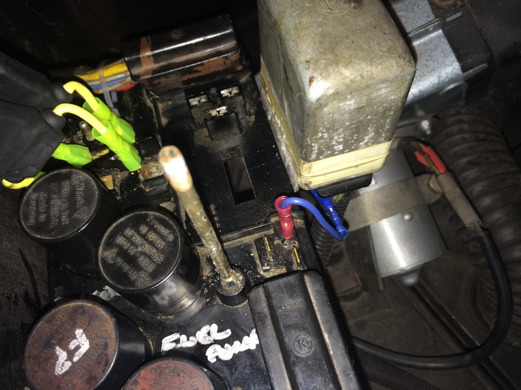
Remote Locate Voltage Regulator
I moved relocated the voltage regulator. Given the harness plug is exactly the same and plugs right into the VR, I don't know why Porsche decided to run that current through the relay plate. Maybe just ease of production and mounting? Regardless, mine is no longer mounted in the stock location; easiest way was to flip it around so it was off the board and plugging the harness straight into the VR itself. You can tie-wrap it if you think the harness might vibrate off.
A solid state relay is in my near future, too.
Relocate fuses
I've never been a fan of those old ceramic (now plastic) fuses. Many a time in this car and its VW air-cooled predecessors I've had to spin the fuses to get them to re-engage with the rest of reality. That resistance is, no doubt, causing heat. So I bought a couple of ATC fuse holders from NAPA and used some female push-on connectors to replace those old fuses.
I had to trim the fuse holder blades slightly with shears to fit inside the standard female connector, just a touch each side, and those old fuses can still be installed.
Better yet, it still fits within the standard relay plate cover.
Ignore the double 30A fuses in there, it's for the photo only. I'll get the right ones for installation (8A and 25A, right?)
Let's see if we can make this guy last a bit longer.
Greg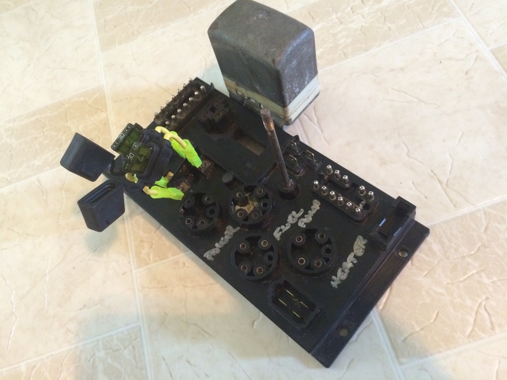
Posted by: BillC Aug 20 2016, 10:09 AM
Nice job!
Just so you know, they do make 3/8" wide female spade connectors. Here's a link to https://www.amazon.com/Calterm-Piece-Disconnect-Female-12-10/dp/B007TPD4ZC/ref=sr_1_cc_1?s=aps&ie=UTF8&qid=1471709184&sr=1-1-catcorr&keywords=.370+female I have also found them at the local FLAPS.
Also, Brad Mayeur sells rebuilt relay boards. He's out of stock right now, but expects more in soon.
Posted by: GregAmy Aug 20 2016, 10:48 AM
Thanks, Yeah that ^^^ would have been good to know, then no mods necessary.
Below is a photo of mine after the swap; not so surprisingly, failures below the VR and fuel pump fuse.
Still fighting an intermittent connection from T14-14 to the fuel pump fuse, the power for the fuel pump. I don't think the problem was there before, because the blower uses the same power source and I did not have a problem with it (I used the blower motor as a test for power, and it always worked). So I either have a bad replacement board, or there's just a gimpy connection or terminal in the wiring harness. It's running now, so I'll get it sorted.
Thanks!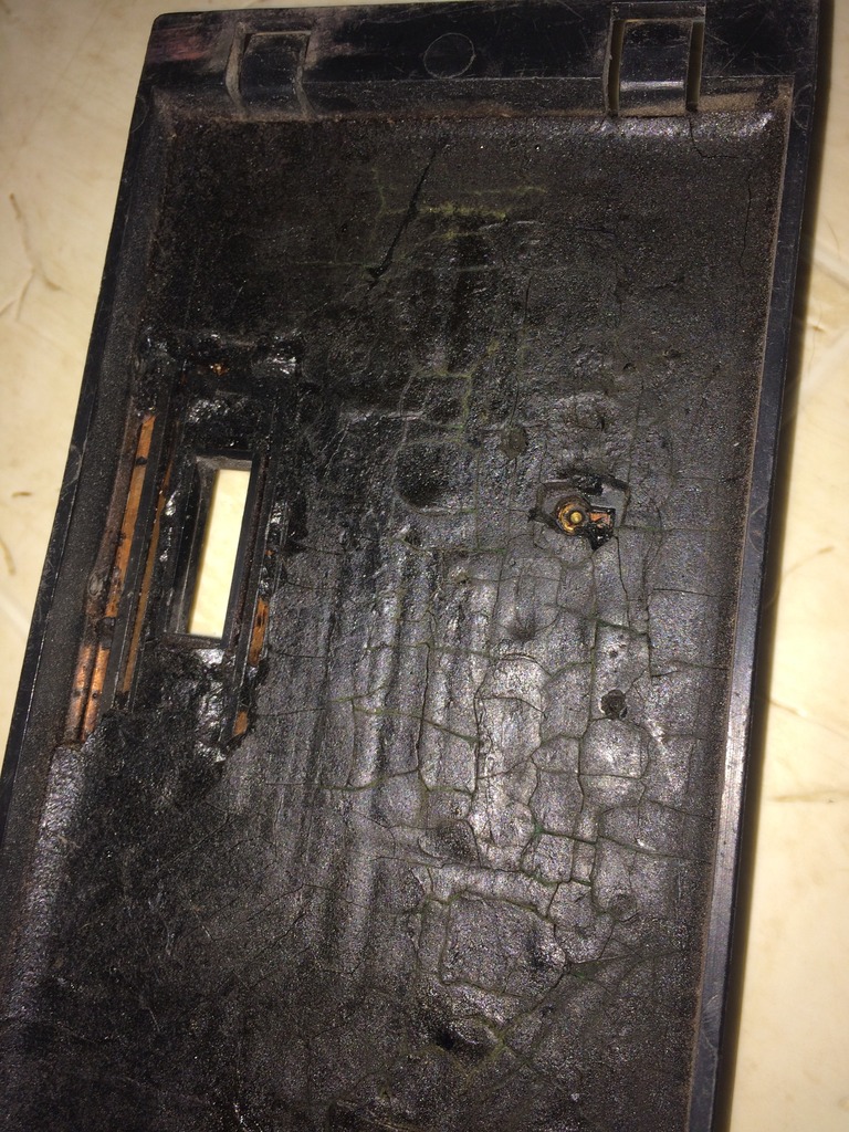
Posted by: GregAmy Aug 20 2016, 12:16 PM
Another note: I chose ATC fuses because I replaced my fusebox up front with one from JWest, and I'm using the Pelican "hot start relay"; both use ATC fuses. If that wasn't the case I'd have used ATO mini fuses for this instead.
I did find one other issue. The T14 wiring harness plug, the 14-pin one next to the VR, has the left end of the plastic busted out, partially exposing pins 13 and 14. Looks like a prior owner may have levered it off sideways, breaking that hind end of the plastic pin holder. Pin 14 is the power source to the fuse that supplies the fuel pump, blower motor, and rear defroster; pin 13 is the output to the fuel pump. Either one of those could have potentially been a core problem. Both have been tweaked to ensure better security of reality flow between the harness and relay board.
Posted by: ejm Aug 20 2016, 12:32 PM

I moved relocated the voltage regulator. Given the harness plug is exactly the same and plugs right into the VR, I don't know why Porsche decided to run that current through the relay plate.
Don't forget the connection to the warning light is thru the relay board
Posted by: GregAmy Aug 20 2016, 12:59 PM
Ok, that's something I hadn't realized. I see it now on the wiring diagrams: T14-2 goes to one side of the light.
I'm running a voltmeter in the center console and the GEN light fails off, so I'm OK. But for others that aren't you can piggyback a jumper from the red wire on the harness to the D+ pin on either board plug, the one on the upper right of the triangle (where the red wire plugged in). That will connect through the trace to the T14 wiring harness and your GEN light will continue to work.
EDIT: A bit inelegant, but GEN light is working again.
Powered by Invision Power Board (http://www.invisionboard.com)
© Invision Power Services (http://www.invisionpower.com)