Printable Version of Topic
Click here to view this topic in its original format
914World.com _ 914World Garage _ MicroSquit Conversion
Posted by: Mblizzard Oct 3 2016, 07:18 AM
I am pretty happy with my stock FI. But after seeing some of the setups at Okteenerfest, I thought this might be worth trying.
The stock system is not easy to modify and get things running correctly. I spent a lot of time making minor adjustments by trial and error. While I am not looking for huge HP gains or anything, it is pretty clear that the mods I have could potentially benefit from a bit more precise control.
Going to start with fuel only at this point to get things going and see where it leads me. Any help or suggestions for set up would be appreciated.
Posted by: 76-914 Oct 3 2016, 07:35 AM
![popcorn[1].gif](style_emoticons/default/popcorn[1].gif)
Posted by: GregAmy Oct 3 2016, 08:01 AM
I've been giving this a lot of thought. I'm a big fan of Mega/Microsquirt and once installed it's a breeze to tune.
My thoughts were along the line of:
- Use stock injectors, fuel lines, manifold, throttle body
- Use stock dizzy signal for inferred crank position sensor
- Install temp sensor in manifold hole for IAT
- Use MS internal MAP
- Design up a TPS replacement (either mounted directly to TB or a string potentiometer mounted remotely)
- Wideband O2 input for closed loop tuning
- Contract Bowlsby to manufacture a replacement harness
It won't be particularly difficult, but will require time and funds to initially setup.
Subscribing...
Posted by: McMark Oct 3 2016, 08:03 AM
I have all the pieces I used on my car. Working on a new injector setup right now.
Posted by: Mblizzard Oct 3 2016, 08:05 AM

I have all the pieces I used on my car. Working on a new injector setup right now.
Yep you owe me the TPS bracket and TPS! Well owe is a little strong. You said you would get me a cost.
Posted by: McMark Oct 3 2016, 08:07 AM
 Done!
Done!
Posted by: Mblizzard Oct 3 2016, 08:08 AM
I've been giving this a lot of thought. I'm a big fan of Mega/Microsquirt and once installed it's a breeze to tune.
My thoughts were along the line of:
- Use stock injectors, fuel lines, manifold, throttle body
- Use stock dizzy signal for inferred
- Install temp sensor in manifold hole for IAT
- Use MS internal MAP
- Design up a TPS replacement (either mounted directly to TB or a string potentiometer mounted remotely)
- Wideband O2 input for closed loop tuning
- Contract Bowlsby to manufacture a replacement harness
It won't be particularly difficult, but will require time and funds to initially setup.
Subscribing...
Pretty much what I am looking at but I am not so sure how to use stock Dizzy for variable timing/crank position sensor.
Looking at the simplicity of the wiring (of course this is without having done a single thing but order parts) it seems that this will be relatively easy to "self" wire.
Posted by: GregAmy Oct 3 2016, 08:18 AM
It will be easy to self wire. However, if you want to make it available to the community - or want to market a kit to help recover costs - then it's even easier to tell them to "go there" for the harness, and "there" for the MS, and "there" for the TPS, etc and "here's how to install it" and "here's the thread where the community posts our tunes for the varying setups". Soup.
Posted by: Mblizzard Oct 3 2016, 08:38 AM
It will be easy to self wire. However, if you want to make it available to the community - or want to market a kit to help recover costs - then it's even easier to tell them to "go there" for the harness, and "there" for the MS, and "there" for the TPS, etc and "here's how to install it" and "here's the thread where the community posts our tunes for the varying setups". Soup.
True. But given my level of expertise in this area I am not sure how many will want to follow my lead!
The one thing that I can say is that from a cost view point, this conversion seems to represent a very interesting break point between repairing a stock system and converting. Looking at just over $500 for the parts makes this very interesting.
To be clear, my stock system is going on the shelf to be used again at some point.
Posted by: plays with cars Oct 3 2016, 09:34 AM
Mike, I think you're concern is justified about using the stock dizzy as an inferred crank position sensor. I would not do it. Particularly if you have vision to expand and ultimately use MS for ignition control as well. You would ultimately be installing a crank trigger wheel and sensor anyway.
There is huge potential for improved drivability, performance, and economy if you have 3D mapping capability for both fuel and ignition. I believe that the factory FI system has a 3D map already for fuel (using points in the dizzy for engine speed and manifold pressure for load sensing) but the distributor really only knows engine rpm. The vacuum canister does not do a good job reacting to load; it's primarily an emission device.
You're right to step into it one system at a time, but I would definitely plan to include ignition in your project. FYI I'm currently in the process of adapting a MegaJolt system, which is an ignition only variant of MS, onto the 2.4 MFI engine in my car. I tried tuning the ignition and the MFI at the same time but kept running into situations where i didn't know which system was at fault for running problems. I've now gone back to a distributor until I get the MFI tuned, then I'll start on the ignition again.
Posted by: Mblizzard Oct 3 2016, 11:15 AM
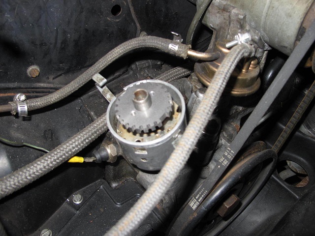
Still asking questions. A number of people have confirmed that the stock CHT will work with this system. Because this system is a bit more sensate to noise it is designed to have the grounds loop back to the unit or essentially use a 2 wire sender. Of course the stock CHT is a single wire that is grounded directly to the engine.
Most of the modern 2-wire units are 3/8 NPT and the stock CHT is 10 mm x 1. Very close I know but has anyone ever seen a 10mm x 1 to 3/8 NPT adaptor?
Posted by: JamesM Oct 3 2016, 11:53 AM
All sorts of cool stuff
http://www.thedubshop.net/products-c17av
Posted by: jcd914 Oct 3 2016, 04:50 PM
Still asking questions. A number of people have confirmed that the stock CHT will work with this system. Because this system is a bit more sensate to noise it is designed to have the grounds loop back to the unit or essentially use a 2 wire sender. Of course the stock CHT is a single wire that is grounded directly to the engine.
Most of the modern 2-wire units are 3/8 NPT and the stock CHT is 10 mm x 1. Very close I know but has anyone ever seen a 10mm x 1 to 3/8 NPT adaptor?
I believe the 911 3.2 CHT is 10mm x 1.0mm and the later one "(1988 on? ) were 2 wire harnesses, including a ground wire.
Jim
Posted by: cgnj Oct 4 2016, 04:30 AM
Hi,
I thought about about all of these issues while I was planning how to execute my MS conversion. Just replacing or repairing the stock MPS will cover most of the cost of the conversion.
If I were going to do a motor up to 2056, this is what I would do.
Microsquirt so all the controls can be in the engine bay and it will be easier to revert back to stock.
Crank position sensor and trigger wheel.
Cam position sensor
Coil on plug
1.8 plenum or a vanagon 2.1 plenum. (I measured the volume of these. There was a negligible difference). Vanagon plenum will allow a larger throttle body without as much work. I will have to check, but I think the vanagon throttle body is marginally bigger than the stock 2.0. I had a discussion with a member regarding these style plenums vs. 2.0 plenum. The theory is that the intake charge loses less velocity since it doesn't hit the floor before entering the runner.
I think this ends up being the cleanest installation.
My two cents, feel free to flame me.
Carlos
Posted by: Mblizzard Oct 4 2016, 06:05 AM
Hi,
I thought about about all of these issues while I was planning how to execute my MS conversion. Just replacing or repairing the stock MPS will cover most of the cost of the conversion.
If I were going to do a motor up to 2056, this is what I would do.
Microsquirt so all the controls can be in the engine bay and it will be easier to revert back to stock.
Crank position sensor and trigger wheel.
Cam position sensor
Coil on plug
1.8 plenum or a vanagon 2.1 plenum. (I measured the volume of these. There was a negligible difference). Vanagon plenum will allow a larger throttle body without as much work. I will have to check, but I think the vanagon throttle body is marginally bigger than the stock 2.0. I had a discussion with a member regarding these style plenums vs. 2.0 plenum. The theory is that the intake charge loses less velocity since it doesn't hit the floor before entering the runner.
I think this ends up being the cleanest installation.
My two cents, feel free to flame me.
Carlos
I hope there are no flames! In the thread or the car!
I have been looking at this a while and I initially want a dependable and adjustable fuel management system. My current set up runs well but the variables are just too hard to control.
So I am doing fuel first with stock intake. I have a very good 123 electronic dizzy so I am going to ride that for a while.
What I am looking at now is how to set it up to use the temp range in the CHT and possibly look at adding my Dakota CHT gauge as an input.
Posted by: jd74914 Oct 4 2016, 06:19 AM
Does the Dakota CHT gauge have any analog (voltage) outputs? The actual CHT sensor is a type K thermocouple, so you'll need an amplifier to read it into the ECU. I've used some of the cheap amplifiers on eBay for small projects and been pretty happy with them.
Mario @ TheDubShop has a pretty slick crank trigger setup which isn't too expensive. If you're going for simple to start you can go wasted spark/injection with just that crank trigger.
I would do some looking into controlling ignition too (I know you have the cool A123 dizzy) because once you start modifying injection you're probably going to want to jump right into modifying ignition too. 
Posted by: McMark Oct 4 2016, 07:16 AM
http://www.914world.com/bbs2/index.php?showtopic=294539&hl=
Never had a ground loop problem with that sensor.
Posted by: Mblizzard Oct 4 2016, 08:18 AM
http://www.914world.com/bbs2/index.php?showtopic=294539&hl=
Never had a ground loop problem with that sensor.
Agree on use of this sensor. But I was looking to use the actual temp generated by the Dakota sensor to tell the ECU to enrich on certain conditions like climbing hills where the CHT may increase quickly.
Now I don't know enough about the ECU yet and this might be a moot point after everything is tuned. But after seeing how quickly the cylinder temps can change I thought if this was possible it would just be an added layer of protection.
I am checking on how the Dakota operates but I think it is a temp resistance set up.
Posted by: Mblizzard Oct 4 2016, 11:01 AM
Does the Dakota CHT gauge have any analog (voltage) outputs? The actual CHT sensor is a type K thermocouple, so you'll need an amplifier to read it into the ECU. I've used some of the cheap amplifiers on eBay for small projects and been pretty happy with them.
Mario @ TheDubShop has a pretty slick crank trigger setup which isn't too expensive. If you're going for simple to start you can go wasted spark/injection with just that crank trigger.
I would do some looking into controlling ignition too (I know you have the cool A123 dizzy) because once you start modifying injection you're probably going to want to jump right into modifying ignition too.
Correct on the Type K and the voltage output is in the mV range so not very useful as is. Contacted Dakota and they don't have an way to output the voltage. So nice thought, difficult to implement.
Posted by: Mark Henry Oct 4 2016, 03:20 PM
If you use the stock 914 injectors (low impedance) you have to use the resistor pack or you will fry your board.
I doubt if you see any real improvement over the stock FI on a bone stock engine. But like said if your MPS is shot or if you plan on future bigger engine/cam then it will pay off then.
I first ran my SDS on my stock 1.8, no power or MPG improvement, but it was a good engine to learn how to use the system.
Posted by: Mblizzard Oct 4 2016, 05:36 PM
If you use the stock 914 injectors (low impedance) you have to use the resistor pack or you will fry your board.
I doubt if you see any real improvement over the stock FI on a bone stock engine. But like said if your MPS is shot or if you plan on future bigger engine/cam then it will pay off then.
I first ran my SDS on my stock 1.8, no power or MPG improvement, but it was a good engine to learn how to use the system.
Yep resistors on way! But I have a 2056 with big valve heads. I am expecting one-million HP!
Expect to take the engine down and split the case next time to add a cam at some point. Then even more HP!
Really just looking for a way to tune what I have well and move into other HP areas.
Posted by: Dtjaden Oct 4 2016, 05:44 PM
Some comments on my 2 year journey with Megasquirt:
1. Install a crank trigger while you have the engine out of the car. Mario at the DubShop sells the one I used at a very reasonable price. I believe McMark also sells one.
While injection control could possibly work with less than a 36-1 trigger, ignition control would never be accurate enough. I am also concerned that a distributor based control would have too much trigger float because of the backlash in the distributor gears.
2. You can definitely use the existing injectors (2 liter), but have them rebuilt and flow tested. I used WitchHunter for this. You can also drive the injectors without resistor packs (which slow their response) by using a peak and hold driver board form JBPerf or DIYAutotune. You will need the flow rate of the injectors at the fuel pressure you decide on and the injector dead-time. I can give you those for my setup but yours may differ. They are not hard to calculate.
3. Once you decide to add ignition control it is almost trivial to get started with this. I used individual GM LS3 ignition coils which can be directly driven by the Megasquirt system. For a start at timing you can duplicate the the timing of the 914 advance curve and then go from there.
4. I tried using the stock CHT sensor - I went through 2 - and finally settled on the one sold by the DubShop. Its based of a GM sensor and is much more consistent. I had a lot of drift with the stock sensors. By the way, once the engine reaches normal operating temperature the CHT has little effect.
5. My throttle position sensor is a lightly used Bosch TPS that I adapted to the stock throttle body using a low tech aluminum plate. You can find this on numerous BMWs at your local junk yard or on ebay for around $30.
6. If you want reliable startup under varying temperatures you will need an idle control valve. I am again using a used Bosch ICV and as with the TPS this can be found on BMWs and others or ebay for $30 - 40. This is a PWM valve, not a stepper based valve.
7. To start tuning you can use the map that TunerStudio generates. You need to set the baseline tune with all TunerStudio Startup/Idle settings off and the engine fully warmed up. Set the idle using the idle adjustment screw on the throttle body. After that you can use the Startup/Idle settings to get a reliable cold start. If you don't do it this way you will chase your tale for weeks (ask me how I know).
8. If you want to do accurate tuning you will need a wide-band AFR meter. I use the Innovate Motorsports MTX-L for this.
9. I mounted the Megasquirt (not Microsquirt) in the rear trunk and have used WeatherPack connectors for all of the wiring. This includes two 22 pin bulkhead connectors into the engine compartment. I built my own mounting plate for the Megasquirt which includes a fuse panel, relays and breakout terminals for much of the wiring. I can build a 914 engine bay wiring harness for you using the Megasquirt standard wiring colors if you make a definite decision on the location of the Microsquirt/Megasquirt and the rest of the components that you will use.
That's a quick summary. If you have questions let me know.
By the way, on the drive to Medford and back I got near 40 MPG driving at 75 plus MPH.
Darryl
Posted by: porsche913b_sp Oct 4 2016, 06:18 PM
Posted by: Porschef Oct 4 2016, 07:13 PM
By the way, on the drive to Medford and back I got near 40 MPG driving at 75 plus MPH.
Darryl
BOOYAH!! Awesome. And there ain't a plug n' play for dummies like myself? BTW, how were your head temps?
Posted by: Dtjaden Oct 4 2016, 08:38 PM
I think you could contact Mario at the DubShop or Mark at Origional Customs. I believe both would provide turnkey systems for the type 4. But without controlling most of the engine parameters it's not easy. The 1.7, 1.8 and 2.0L engines are each different. Then add the variations of differing cams, ignition, intakes, extended engine sizes and 40+ year old parts. If you try to minimize variations by providing all of the components and parts that eliminate commercial risk I'm not sure that many 914 owners would pay for the system.
On a do it yourself basis I probably spent about $2,500 (maybe more). The packaging of the various components would add many hours of labor and support of customers many more so I can't see selling a turnkey system that would include FI and ignition control for under $4,500.
On the Medford drive my CHT gauge was not working so I'm not sure of the head temps on that trip. My oil temps stayed in the range of 180 - 220 with the upper end during the drive through the passes on I5 between Redlands, CA and Ashland, OR.
I can run on the lean side when not under load. For example light load in the 15's. Under load more like 13 - 13.5.
P.S. - my engine is 2056 cc with about 9.2 cr and a Webcam #86
By the way, on the drive to Medford and back I got near 40 MPG driving at 75 plus MPH.
Darryl
BOOYAH!! Awesome. And there ain't a plug n' play for dummies like myself? BTW, how were your head temps?
Posted by: Mblizzard Oct 5 2016, 07:48 AM
Some comments on my 2 year journey with Megasquirt:
1. Install a crank trigger while you have the engine out of the car. Mario at the DubShop sells the one I used at a very reasonable price. I believe McMark also sells one.
While injection control could possibly work with less than a 36-1 trigger, ignition control would never be accurate enough. I am also concerned that a distributor based control would have too much trigger float because of the backlash in the distributor gears.
2. You can definitely use the existing injectors (2 liter), but have them rebuilt and flow tested. I used WitchHunter for this. You can also drive the injectors without resistor packs (which slow their response) by using a peak and hold driver board form JBPerf or DIYAutotune. You will need the flow rate of the injectors at the fuel pressure you decide on and the injector dead-time. I can give you those for my setup but yours may differ. They are not hard to calculate.
3. Once you decide to add ignition control it is almost trivial to get started with this. I used individual GM LS3 ignition coils which can be directly driven by the Megasquirt system. For a start at timing you can duplicate the the timing of the 914 advance curve and then go from there.
4. I tried using the stock CHT sensor - I went through 2 - and finally settled on the one sold by the DubShop. Its based of a GM sensor and is much more consistent. I had a lot of drift with the stock sensors. By the way, once the engine reaches normal operating temperature the CHT has little effect.
5. My throttle position sensor is a lightly used Bosch TPS that I adapted to the stock throttle body using a low tech aluminum plate. You can find this on numerous BMWs at your local junk yard or on ebay for around $30.
6. If you want reliable startup under varying temperatures you will need an idle control valve. I am again using a used Bosch ICV and as with the TPS this can be found on BMWs and others or ebay for $30 - 40. This is a PWM valve, not a stepper based valve.
7. To start tuning you can use the map that TunerStudio generates. You need to set the baseline tune with all TunerStudio Startup/Idle settings off and the engine fully warmed up. Set the idle using the idle adjustment screw on the throttle body. After that you can use the Startup/Idle settings to get a reliable cold start. If you don't do it this way you will chase your tale for weeks (ask me how I know).
8. If you want to do accurate tuning you will need a wide-band AFR meter. I use the Innovate Motorsports MTX-L for this.
9. I mounted the Megasquirt (not Microsquirt) in the rear trunk and have used WeatherPack connectors for all of the wiring. This includes two 22 pin bulkhead connectors into the engine compartment. I built my own mounting plate for the Megasquirt which includes a fuse panel, relays and breakout terminals for much of the wiring. I can build a 914 engine bay wiring harness for you using the Megasquirt standard wiring colors if you make a definite decision on the location of the Microsquirt/Megasquirt and the rest of the components that you will use.
That's a quick summary. If you have questions let me know.
By the way, on the drive to Medford and back I got near 40 MPG driving at 75 plus MPH.
Darryl
Got TPS coming from McMark.
Hoping to not go the crank trigger rout because I have AV. Looking at the Min Can Sync as an option.
I have heard good and bad about use of the Stock CHT. Checking with Mario on the options. The GM NPT threading is not the same as the 10mm x1 stock threading so would you not need an adaptor for that?
Like the idea of the peak and hold but I don't have the abilities to build the electronics and the prebuilt ones seem expensive.
Had not considered idle control valve. I hoped that the warm up programing in the MicroSquirt would address those issues Seem like that was a wrong guess?
Have wideband O2 already installed.
As this will be a build in stages I am not sure I cam plan out the locations of everything in advance. But I would love to see some photos of your install for some ideas.
Lots more questions to follow! Should be receiving my first batch of parts today.
Posted by: Dtjaden Oct 5 2016, 09:10 AM
The DubShop CHT sensor is installed under one of the engine tin screws. It uses the GM sensor element in deferent housing.
If you are going to continue to use the 914 ignition you can't use the DubShop mini cam sync since it replaces the distributor. If you don't want to use a crank trigger wheel (which I strongly reccommend) your only option is using coil/points triggering.
Without using an ICV it will be difficult if not impossible to get hands off (really foot off) start up. You will need to use the accelerator for the first few minutes to keep the engine running until it reaches operating temperature.
Some comments on my 2 year journey with Megasquirt:
1. Install a crank trigger while you have the engine out of the car. Mario at the DubShop sells the one I used at a very reasonable price. I believe McMark also sells one.
While injection control could possibly work with less than a 36-1 trigger, ignition control would never be accurate enough. I am also concerned that a distributor based control would have too much trigger float because of the backlash in the distributor gears.
2. You can definitely use the existing injectors (2 liter), but have them rebuilt and flow tested. I used WitchHunter for this. You can also drive the injectors without resistor packs (which slow their response) by using a peak and hold driver board form JBPerf or DIYAutotune. You will need the flow rate of the injectors at the fuel pressure you decide on and the injector dead-time. I can give you those for my setup but yours may differ. They are not hard to calculate.
3. Once you decide to add ignition control it is almost trivial to get started with this. I used individual GM LS3 ignition coils which can be directly driven by the Megasquirt system. For a start at timing you can duplicate the the timing of the 914 advance curve and then go from there.
4. I tried using the stock CHT sensor - I went through 2 - and finally settled on the one sold by the DubShop. Its based of a GM sensor and is much more consistent. I had a lot of drift with the stock sensors. By the way, once the engine reaches normal operating temperature the CHT has little effect.
5. My throttle position sensor is a lightly used Bosch TPS that I adapted to the stock throttle body using a low tech aluminum plate. You can find this on numerous BMWs at your local junk yard or on ebay for around $30.
6. If you want reliable startup under varying temperatures you will need an idle control valve. I am again using a used Bosch ICV and as with the TPS this can be found on BMWs and others or ebay for $30 - 40. This is a PWM valve, not a stepper based valve.
7. To start tuning you can use the map that TunerStudio generates. You need to set the baseline tune with all TunerStudio Startup/Idle settings off and the engine fully warmed up. Set the idle using the idle adjustment screw on the throttle body. After that you can use the Startup/Idle settings to get a reliable cold start. If you don't do it this way you will chase your tale for weeks (ask me how I know).
8. If you want to do accurate tuning you will need a wide-band AFR meter. I use the Innovate Motorsports MTX-L for this.
9. I mounted the Megasquirt (not Microsquirt) in the rear trunk and have used WeatherPack connectors for all of the wiring. This includes two 22 pin bulkhead connectors into the engine compartment. I built my own mounting plate for the Megasquirt which includes a fuse panel, relays and breakout terminals for much of the wiring. I can build a 914 engine bay wiring harness for you using the Megasquirt standard wiring colors if you make a definite decision on the location of the Microsquirt/Megasquirt and the rest of the components that you will use.
That's a quick summary. If you have questions let me know.
By the way, on the drive to Medford and back I got near 40 MPG driving at 75 plus MPH.
Darryl
Got TPS coming from McMark.
Hoping to not go the crank trigger rout because I have AV. Looking at the Min Can Sync as an option.
I have heard good and bad about use of the Stock CHT. Checking with Mario on the options. The GM NPT threading is not the same as the 10mm x1 stock threading so would you not need an adaptor for that?
Like the idea of the peak and hold but I don't have the abilities to build the electronics and the prebuilt ones seem expensive.
Had not considered idle control valve. I hoped that the warm up programing in the MicroSquirt would address those issues Seem like that was a wrong guess?
Have wideband O2 already installed.
As this will be a build in stages I am not sure I cam plan out the locations of everything in advance. But I would love to see some photos of your install for some ideas.
Lots more questions to follow! Should be receiving my first batch of parts today.
Posted by: Mblizzard Oct 5 2016, 09:40 AM
The DubShop CHT sensor is installed under one of the engine tin screws. It uses the GM sensor element in deferent housing.
If you are going to continue to use the 914 ignition you can't use the DubShop mini cam sync since it replaces the distributor. If you don't want to use a crank trigger wheel (which I strongly reccommend) your only option is using coil/points triggering.
Without using an ICV it will be difficult if not impossible to get hands off (really foot off) start up. You will need to use the accelerator for the first few minutes to keep the engine running until it reaches operating temperature.
The mini cam is the next stage. Starting with the coil for the tac signal for the fuel only stage.
I understand that there might be some variance in the use of the dizzy timing approach but I guess I just don't know enough about the crank trigger to determine why it would be better.
My goals are a low cost, dependable, and drivable system. Not trying to see great HP gains just a reliable system.
Can you point me to an ICV?
Posted by: jd74914 Oct 5 2016, 10:21 AM
Hoping to not go the crank trigger rout because I have AV. Looking at the Min Can Sync as an option.
What is AV?
The Mini Cam Sync only gives you one pulse for determining engine phasing; for injection you really need to have more resolution. I guess you could technically use it (if the software allows), but you'd only get one trigger every 2 revolutions.
Something like this is much better. Just like the mini sync it can be installed without removing the engine. The difference is that it has multiple teeth so you could use it as a replacement crank trigger. I have one and Jarred really did a nice job making it.
http://www.914world.com/bbs2/index.php?showtopic=247915&hl=
Posted by: jd74914 Oct 5 2016, 10:30 AM
Oops, just read your more recent post and saw that you want to use the coil for timing. Having increased resolution on the crank allows you better engine positioning accuracy so you can tune injection/ignition times better. Different applications, but generally better engine position accuracy results in a crisper tune.
With a T4 engine, the dizzy is driven right off of the motor so timing accuracy is very good compared to most engines. On engines with a belt/chain timing drive, there can be 2-5 degrees (or more) of error depending on engine speed, etc.
Posted by: Mblizzard Oct 5 2016, 10:58 AM
Hoping to not go the crank trigger rout because I have AV. Looking at the Min Can Sync as an option.
What is AV?
The Mini Cam Sync only gives you one pulse for determining engine phasing; for injection you really need to have more resolution. I guess you could technically use it (if the software allows), but you'd only get one trigger every 2 revolutions.
Something like this is much better. Just like the mini sync it can be installed without removing the engine. The difference is that it has multiple teeth so you could use it as a replacement crank trigger. I have one and Jarred really did a nice job making it.
http://www.914world.com/bbs2/index.php?showtopic=247915&hl=
Sorry AC = Air conditioning pulley is in the space the trigger would need to go.
Posted by: Mblizzard Oct 5 2016, 11:01 AM
Hoping to not go the crank trigger rout because I have AV. Looking at the Min Can Sync as an option.
What is AV?
The Mini Cam Sync only gives you one pulse for determining engine phasing; for injection you really need to have more resolution. I guess you could technically use it (if the software allows), but you'd only get one trigger every 2 revolutions.
Something like this is much better. Just like the mini sync it can be installed without removing the engine. The difference is that it has multiple teeth so you could use it as a replacement crank trigger. I have one and Jarred really did a nice job making it.
http://www.914world.com/bbs2/index.php?showtopic=247915&hl=
That looks like what I would want. and the coil packs are not expensive.
Posted by: cgnj Oct 5 2016, 11:35 AM
Hoping to not go the crank trigger rout because I have AV. Looking at the Min Can Sync as an option.
What is AV?
The Mini Cam Sync only gives you one pulse for determining engine phasing; for injection you really need to have more resolution. I guess you could technically use it (if the software allows), but you'd only get one trigger every 2 revolutions.
Something like this is much better. Just like the mini sync it can be installed without removing the engine. The difference is that it has multiple teeth so you could use it as a replacement crank trigger. I have one and Jarred really did a nice job making it.
http://www.914world.com/bbs2/index.php?showtopic=247915&hl=
Sorry AC = Air conditioning pulley is in the space the trigger would need to go.
Hi,
Member dlee has made a adaptor setup that will allow you to use a 36-1 crank trigger.
I just touched it last night. I will grab it and mock it up on the engine stand this evening. Crank position sensor in distributor will take away sequential fire option. It does reduce the number of cuts in the engine also.
I'm old, I need my AC.
Carlos
Posted by: cgnj Oct 5 2016, 11:44 AM
9. I mounted the Megasquirt (not Microsquirt) in the rear trunk and have used WeatherPack connectors for all of the wiring. This includes two 22 pin bulkhead connectors into the engine compartment. I built my own mounting plate for the Megasquirt which includes a fuse panel, relays and breakout terminals for much of the wiring. I can build a 914 engine bay wiring harness for you using the Megasquirt standard wiring colors if you make a definite decision on the location of the Microsquirt/Megasquirt and the rest of the components that you will use.
That's a quick summary. If you have questions let me know.
By the way, on the drive to Medford and back I got near 40 MPG driving at 75 plus MPH.
Darryl
Megasquirt in the trunk never crossed my mind. This was timely, saves me from putting a hole through the firewall.
40 MPG? What motor?
Carlos
Posted by: N_Jay Oct 5 2016, 12:11 PM
. . . .Crank position sensor in distributor will take away sequential fire option. . . .
Why is that?
Posted by: Mark Henry Oct 5 2016, 12:48 PM
Oops, just read your more recent post and saw that you want to use the coil for timing. Having increased resolution on the crank allows you better engine positioning accuracy so you can tune injection/ignition times better. Different applications, but generally better engine position accuracy results in a crisper tune.
With a T4 engine, the dizzy is driven right off of the motor so timing accuracy is very good compared to most engines. On engines with a belt/chain timing drive, there can be 2-5 degrees (or more) of error depending on engine speed, etc.
Well debateable ...crankfire is still not as accurate as many believe, a 2-4 degree variance would still be the acceptable norm. As far as the dizzy drive goes it only becomes less accurate when you decelerate, and that doesn't really matter. The performance gain that most are seeing comes from the advance curve and higher voltages of modern coils.
Same debate as far as sequential and batch fired injectors. The only real advantage of sequential fuel injection is an emissions and maybe slightly better MPG. And this is at lower RPM's, over say 4000 RPM most of this becomes a moot point.
BTW I've been running EFI and crankfire since 2003.
Posted by: Mblizzard Oct 5 2016, 01:13 PM
Oops, just read your more recent post and saw that you want to use the coil for timing. Having increased resolution on the crank allows you better engine positioning accuracy so you can tune injection/ignition times better. Different applications, but generally better engine position accuracy results in a crisper tune.
With a T4 engine, the dizzy is driven right off of the motor so timing accuracy is very good compared to most engines. On engines with a belt/chain timing drive, there can be 2-5 degrees (or more) of error depending on engine speed, etc.
Well debateable ...crankfire is still not as accurate as many believe, a 2-4 degree variance would still be the acceptable norm. As far as the dizzy drive goes it only becomes less accurate when you decelerate, and that doesn't really matter. The performance gain that most are seeing comes from the advance curve and higher voltages of modern coils.
Same debate as far as sequential and batch fired injectors. The only real advantage of sequential fuel injection is an emissions and maybe slightly better MPG. And this is at lower RPM's, over say 4000 RPM most of this becomes a moot point.
BTW I've been running EFI and crankfire since 2003.
As I tend to be, I am so far ahead of myself it is not even funny. Just got email that my MicroSquirt was delivered and was left on the front porch. So I am all ready looking at jumping to the ignition and sequential injection timing and I have not even opened the first box yet!
For my engine I think I will be spending most of my time below the 4K mark so the sequential fuel injection is desirable to me but obviously not a requirement.
But I would like to go to a more modern coil set up and have the ability to control my timing. If there is a dizzy based option to control the timing I would be good with that and let the sequential go.
Something like this seems perfect but not sure where to find.
Posted by: Mark Henry Oct 5 2016, 01:20 PM
Yep, I'm just saying don't get hung up on it.
MS/micro squirt can be run on batch fire, you could worry about sequential later. Just might be easier during the learning curve.
I'm sure you can fire the ignition off of pertronix's, etc. even points, just lock out the dizzy advance and you have programmable ignition through the MS.
Posted by: cgnj Oct 5 2016, 02:04 PM
This is the Dubshop cam position sensor $155.00 http://thedubshop.goodsie.com/ignition
Can do batch or sequential. It is pre-order now. I have it installed and my engine is on the stand. I'll add that to my picture list.
Have we hijacked this thread yet? If so, I'm sorry.
Carlos
Posted by: Mblizzard Oct 5 2016, 02:27 PM
This is the Dubshop cam position sensor $155.00 http://thedubshop.goodsie.com/ignition
Can do batch or sequential. It is pre-order now. I have it installed and my engine is on the stand. I'll add that to my picture list.
Have we hijacked this thread yet? If so, I'm sorry.
Carlos
Nope on the hijack. Lots of good information.
Would like to see if this could be done initially for fuel only for around $600. So far that seems possible assuming our time is free.
Posted by: Dtjaden Oct 5 2016, 03:52 PM
This is the Dubshop cam position sensor $155.00 http://thedubshop.goodsie.com/ignition
Can do batch or sequential. It is pre-order now. I have it installed and my engine is on the stand. I'll add that to my picture list.
Have we hijacked this thread yet? If so, I'm sorry.
Carlos
Nope on the hijack. Lots of good information.
Would like to see if this could be done initially for fuel only for around $600. So far that seems possible assuming our time is free.
Any RPM signal device that installs in the distributor or replaces the distributor immediately requires MS be used for both FI and ignition.
Posted by: Mblizzard Oct 5 2016, 04:49 PM
First box of goodies!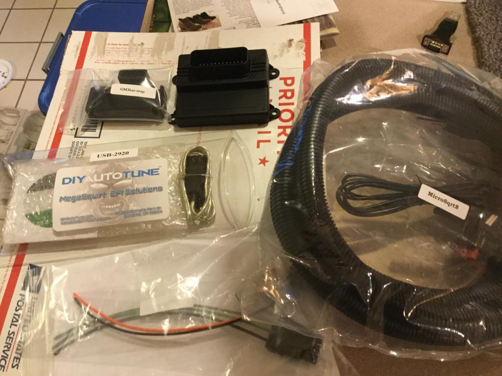
Posted by: Dtjaden Oct 5 2016, 11:33 PM
For anyone looking for a packaged solution for under $1,000 here is why it can't be done (even if you DIY). Here is what you need:
- Throttle body modify for the TPS - exchange price - $50
- Fuel injectors rebuilt and flow tested - exchange price $200
- Cylinder head temp sensor - $40
- RPM signal sensor $200
- Intake air temp sensor $20
- GM LS2 ignition coils, 4 required $100
- Throttle position sensor $30
- FI fuel pump and filters $150
- Fuel pressure regulator $100
- Microsquirt with harness - $370
- Injector driver board $100
- Fuel pump relay and wiring $15
- Power relay & wiring $20
- mounting board $10
- Fuse panel & fuses $20
- Various connectors - $50
- Package labor $500
-----------
Total. $1,975
Can it be done for less than this? Sure but not as a commercial product. And this price does not really equate to a commercial product because there is no profit margin. A minimal margin of 30% would equate to a selling price of $2,575.
Could you reduce the cost of or eliminate some of the line items? Sure, but again, not as a commercial product. You could source used LS 2 ignition coils, use the existing fuel pump and pressure regulator, skip the rebuild and testing of the fuel injectors or even do FI only. But you can't rely on used parts on a product for resale.
FI only, using the coil signal as the RPM trigger would cut about $300 from the cost but you would still have a margined selling price of $2,000.
Finally, you would need to take into account the engine configuration. 1.7, 1.8, 2.0L engines would each have unique tuning requirements. And beyond standard engine configurations such as increased displacement, compression ratio, camshaft, etc each adds a new tuning requirement. Packaged solutions are difficult if the installation environment is not controlled.
This is why the DubShop and Origional Customs sell their products at the prices they have set.
So, if 10 914 owners with stock 2.0L engines wanted to step up the plate (go SF Giants)
I would be happy to package a solution at the prices outlined above. Support past an initial period of 5 hours would be at $75 per hour. Or contact Mario at the DubShop or Mark at Origional Customs.
Posted by: McMark Oct 6 2016, 07:37 AM
I don't think MicroSquirt does sequential injection. Just batch. Pair the cylinders like the factory did for the injection harness 1/4 and 3/2. This is better for injectors, but WRONG for ignition.
I tried using a signal from a distributor a long time ago and never got it to trigger reliably. When I would crank, the RPM readout on the laptop would jump all over, varying wildly, and illustrating how hard of a time MS was having reading the coil signal. When I installed a crank trigger setup, it was rock solid, even under just cranking. So much better. The distributor based wheel may work well. It's not ideal, and I haven't used one, but I can't think of any reason it wouldn't work well enough.
Posted by: Mblizzard Oct 6 2016, 10:38 AM
I don't think MicroSquirt does sequential injection. Just batch. Pair the cylinders like the factory did for the injection harness 1/4 and 3/2. This is better for injectors, but WRONG for ignition.
I tried using a signal from a distributor a long time ago and never got it to trigger reliably. When I would crank, the RPM readout on the laptop would jump all over, varying wildly, and illustrating how hard of a time MS was having reading the coil signal. When I installed a crank trigger setup, it was rock solid, even under just cranking. So much better. The distributor based wheel may work well. It's not ideal, and I haven't used one, but I can't think of any reason it wouldn't work well enough.
Mark I am curious on the paring of the injectors. I have not read everything yet but I thought it was all batch fire meaning that all of the injectors fired at once. What you present seems to suggest the is some way to time each bank?
Posted by: Mueller Oct 6 2016, 10:51 AM
Hoping to not go the crank trigger rout because I have AV. Looking at the Min Can Sync as an option.
What is AV?
The Mini Cam Sync only gives you one pulse for determining engine phasing; for injection you really need to have more resolution. I guess you could technically use it (if the software allows), but you'd only get one trigger every 2 revolutions.
Something like this is much better. Just like the mini sync it can be installed without removing the engine. The difference is that it has multiple teeth so you could use it as a replacement crank trigger. I have one and Jarred really did a nice job making it.
http://www.914world.com/bbs2/index.php?showtopic=247915&hl=
Wow, that thread brings back some memories!
http://www.914world.com/bbs2/index.php?showtopic=24043&hl=
If Jarred doesn't have anymore and has no interest in making more , i could whip a few out for you.
Posted by: Mblizzard Oct 6 2016, 11:25 AM
Hoping to not go the crank trigger rout because I have AV. Looking at the Min Can Sync as an option.
What is AV?
The Mini Cam Sync only gives you one pulse for determining engine phasing; for injection you really need to have more resolution. I guess you could technically use it (if the software allows), but you'd only get one trigger every 2 revolutions.
Something like this is much better. Just like the mini sync it can be installed without removing the engine. The difference is that it has multiple teeth so you could use it as a replacement crank trigger. I have one and Jarred really did a nice job making it.
http://www.914world.com/bbs2/index.php?showtopic=247915&hl=
Wow, that thread brings back some memories!
http://www.914world.com/bbs2/index.php?showtopic=24043&hl=
If Jarred doesn't have anymore and has no interest in making more , i could whip a few out for you.
Not there yet but this does hold interest for me.
Posted by: aircooledtechguy Oct 6 2016, 10:40 PM
I own, run and have installed virtually every product Mario offers at thedubshop. His products are the best I've used and his after sale service is second to none.
The mini cam sensor enables full sequential injection and/or spark. For most folks, it's not really necessary. Sequential injection can on the right motor get a couple more hp and slightly better mpgs, but where it really helps is on motors with high lift & high overlap/long duration cams. It greatly smooths the idle and low rpms. I'm using one with LS2 coils on my race motor that has a pretty wild cam and it idles like stock @ 8-900 rpms. It would never do that in batch mode.
IMHO I would go with one of Mario's own ECUs. It can be used to run sequential or batch injection/spark. It comes with 2 map sensors as well as several other features. It also includes an on-board WBO2 controller!! When I convert my bus to MS, it'll have a Dubshop ECU.
I would highly recommend using a 36-1 trigger wheels rather than a bosch dizzy for triggering spark. The only dizzy I have ever used that comes close to the accuracy of his kit is a Mallory Unlite. A factory Bosch dizzy is all over the place with timing. They can vary by as much as 5-7 degrees depending on the wear on the shaft. Bosch dizzys suck IMHO. There's way better out there these days, so why bother with them to control everything??
Posted by: Dtjaden Oct 6 2016, 10:53 PM
I own, run and have installed virtually every product Mario offers at thedubshop. His products are the best I've used and his after sale service is second to none.
The mini cam sensor enables full sequential injection and/or spark. For most folks, it's not really necessary. Sequential injection can on the right motor get a couple more hp and slightly better mpgs, but where it really helps is on motors with high lift & high overlap/long duration cams. It greatly smooths the idle and low rpms. I'm using one with LS2 coils on my race motor that has a pretty wild cam and it idles like stock @ 8-900 rpms. It would never do that in batch mode.
IMHO I would go with one of Mario's own ECUs. It can be used to run sequential or batch injection/spark. It comes with 2 map sensors as well as several other features. It also includes an on-board WBO2 controller!! When I convert my bus to MS, it'll have a Dubshop ECU.
I would highly recommend using a 36-1 trigger wheels rather than a bosch dizzy for triggering spark. The only dizzy I have ever used that comes close to the accuracy of his kit is a Mallory Unlite. A factory Bosch dizzy is all over the place with timing. They can vary by as much as 5-7 degrees depending on the wear on the shaft. Bosch dizzys suck IMHO. There's way better out there these days, so why bother with them to control everything??

Posted by: Java2570 Oct 7 2016, 07:44 AM
I've been talking to Mario @ Dubshop about doing a MS setup for my 2056 build and my list of items will be around $1700. I was contemplating going fuel only but after reading a lot and emailing with Mario, I've gotten on board with doing ignition as well. Nate's threads (and others) have been a good inspiration to do this kind of setup. Hopefully, I'll get it all bought this winter.
Posted by: Mblizzard Oct 7 2016, 08:43 AM
I own, run and have installed virtually every product Mario offers at thedubshop. His products are the best I've used and his after sale service is second to none.
The mini cam sensor enables full sequential injection and/or spark. For most folks, it's not really necessary. Sequential injection can on the right motor get a couple more hp and slightly better mpgs, but where it really helps is on motors with high lift & high overlap/long duration cams. It greatly smooths the idle and low rpms. I'm using one with LS2 coils on my race motor that has a pretty wild cam and it idles like stock @ 8-900 rpms. It would never do that in batch mode.
IMHO I would go with one of Mario's own ECUs. It can be used to run sequential or batch injection/spark. It comes with 2 map sensors as well as several other features. It also includes an on-board WBO2 controller!! When I convert my bus to MS, it'll have a Dubshop ECU.
I would highly recommend using a 36-1 trigger wheels rather than a bosch dizzy for triggering spark. The only dizzy I have ever used that comes close to the accuracy of his kit is a Mallory Unlite. A factory Bosch dizzy is all over the place with timing. They can vary by as much as 5-7 degrees depending on the wear on the shaft. Bosch dizzys suck IMHO. There's way better out there these days, so why bother with them to control everything??
I think the crank trigger would be better as well. But with my car having AC I don't think I have the space to insert the trigger. So while it may not be perfect, the dizzy options seem to be what's available to me at this point.
Posted by: N_Jay Oct 7 2016, 08:57 AM
I think the crank trigger would be better as well. But with my car having AC I don't think I have the space to insert the trigger. So while it may not be perfect, the dizzy options seem to be what's available to me at this point.
I don't understand why a Dist (with all advance locked out) and a pick up wheel installed would not be just as good as a crank fire set up?
Posted by: Mblizzard Oct 7 2016, 09:10 AM
I think the crank trigger would be better as well. But with my car having AC I don't think I have the space to insert the trigger. So while it may not be perfect, the dizzy options seem to be what's available to me at this point.
I don't understand why a Dist (with all advance locked out) and a pick up wheel installed would not be just as good as a crank fire set up?
As Mark Henry stated, there is some potential "slop" in the dizzy on Decel. But I think the crank may provide more options and potential with the sensors being more standard there are greater options. But while I am still doing research, the dizzy option seems very valid. If it was not an option, then things like the Mini Cam Sync would not exist.
I am waiting to get the details on the mini cam from Mario.
Posted by: Mblizzard Oct 7 2016, 09:59 AM
Ok let’s be clear. I am not no wiring expert! But as I understand things the micro squirt controls the injectors by providing ground. Meaning the controller switches ground on an off as needed to fire the injectors. Because I have low impedance injectors I have to use resistors. Below is the guidance from the manual on how to wire.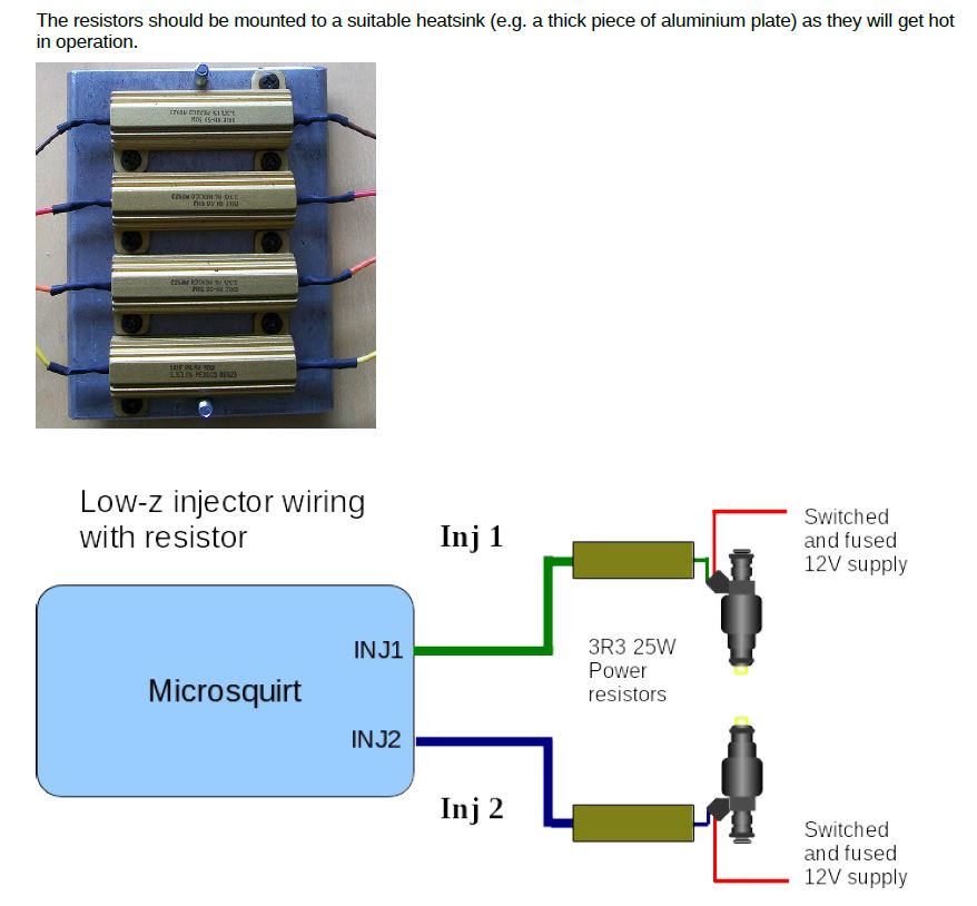
Based on this it shows the resistors on the controller side which is ground. 
This can’t be correct can it? Especially when it stats than an individual resistor is required for each injector.
The resistors have to go on the 12v wire don't they?
Posted by: N_Jay Oct 7 2016, 10:03 AM
Ok let’s be clear. I am not no wiring expert! But as I understand things the micro squirt controls the injectors by providing ground. Meaning the controller switches ground on an off as needed to fire the injectors. Because I have low impedance injectors I have to use resistors. Below is the guidance from the manual on how to wire.
Based on this it shows the resistors on the controller side which is ground.
This can’t be correct can it? Especially when it stats than an individual resistor is required for each injector.
The resistors have to go on the 12v wire don't they?
The order of devices in series is immaterial.
Question, how much voltage and current at are the injectors designed for?
What is the current the MS is designed to sink?
Posted by: cgnj Oct 7 2016, 10:03 AM
I think the crank trigger would be better as well. But with my car having AC I don't think I have the space to insert the trigger. So while it may not be perfect, the dizzy options seem to be what's available to me at this point.
I don't understand why a Dist (with all advance locked out) and a pick up wheel installed would not be just as good as a crank fire set up?
As Mark Henry stated, there is some potential "slop" in the dizzy on Decel. But I think the crank may provide more options and potential with the sensors being more standard there are greater options. But while I am still doing research, the dizzy option seems very valid. If it was not an option, then things like the Mini Cam Sync would not exist.
I am waiting to get the details on the mini cam from Mario.
Hi,
This problem is a distributor issue. I guess if you go thru the trouble of locking it down, it would be less of an issue. It isn't likely that you will see a problem with a cam position sensor.
When you look at the time, effort and money to implement a imperfect mechanical solution, it doesn't make sense. It's applying yesterdays technology today. It would be different if you already had these parts in hand.
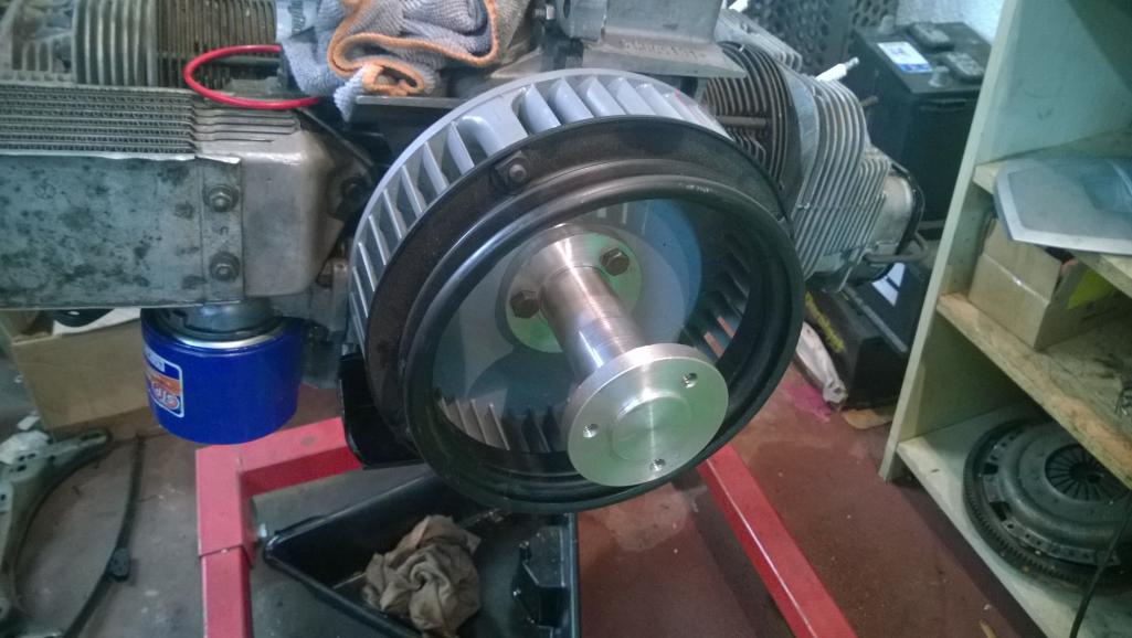
I think you started down this distributor road because of AC. I am 99.9 % certain that the stock AC pulley is not an issue with Original Customs trigger wheel setup. I either gleaned that here or discussed it directly with Mark.
I attached a pic of the AC adaptor that I will be using.
Posted by: cgnj Oct 7 2016, 10:13 AM
I think the crank trigger would be better as well. But with my car having AC I don't think I have the space to insert the trigger. So while it may not be perfect, the dizzy options seem to be what's available to me at this point.
I don't understand why a Dist (with all advance locked out) and a pick up wheel installed would not be just as good as a crank fire set up?
Hi,
It's a part looking for a market. There is no way you could get more resolution than being on the crank, plus you are only going to sense the missing tooth 50% of the time required.
Carlos
Posted by: Dtjaden Oct 7 2016, 11:13 AM
The crankshaft trigger wheel, either the DubShop's or Original Customs', goes between the crankshaft and the fan. It does not space the fan out farther so I don't believe it would have any impact on an A/C fan pulley.
Using the crank sensor wheel does give you the opportunity to implement FI first and add ignition later. A cam (distributor) based RPM sensor forces you to do both FI and ignition at the same time.
Posted by: N_Jay Oct 7 2016, 11:20 AM
Maybe I am not picturing it correctly, but how does it go between the crank and fan and NOT space the fat out further?
It would seem a Dist trigger wheel could easily have two missing teeth and give you the same trigger as a crank wheel, but could also give you came timing should you ever want sequential FI and/or not run wasted spark.
P.S. Not arguing, just asking to learn.
Posted by: jd74914 Oct 7 2016, 11:26 AM
Maybe I am not picturing it correctly, but how does it go between the crank and fan and NOT space the fat out further?
There is a thick washer under the fan that gets replaced.
Posted by: Mblizzard Oct 7 2016, 11:31 AM
Maybe I am not picturing it correctly, but how does it go between the crank and fan and NOT space the fat out further?
There is a thick washer under the fan that gets replaced.
And that is my issue. That washer has already been replaced by the existing pulley for the AC. So I am not sure that I can get everything in there and have it aligned correctly.
Posted by: Mblizzard Oct 7 2016, 11:32 AM
Ok let’s be clear. I am not no wiring expert! But as I understand things the micro squirt controls the injectors by providing ground. Meaning the controller switches ground on an off as needed to fire the injectors. Because I have low impedance injectors I have to use resistors. Below is the guidance from the manual on how to wire.
Based on this it shows the resistors on the controller side which is ground.
This can’t be correct can it? Especially when it stats than an individual resistor is required for each injector.
The resistors have to go on the 12v wire don't they?
The order of devices in series is immaterial.
Question, how much voltage and current at are the injectors designed for?
What is the current the MS is designed to sink?
Lets say the injector resistance is around 2.5 Ohms and I am adding another 3 Ohms so that would be about 2 amps based on 12V.
Posted by: N_Jay Oct 7 2016, 11:46 AM
Ok let’s be clear. I am not no wiring expert! But as I understand things the micro squirt controls the injectors by providing ground. Meaning the controller switches ground on an off as needed to fire the injectors. Because I have low impedance injectors I have to use resistors. Below is the guidance from the manual on how to wire.
Based on this it shows the resistors on the controller side which is ground.
This can’t be correct can it? Especially when it stats than an individual resistor is required for each injector.
The resistors have to go on the 12v wire don't they?
The order of devices in series is immaterial.
Question, how much voltage and current at are the injectors designed for?
What is the current the MS is designed to sink?
Lets say the injector resistance is around 2.5 Ohms and I am adding another 3 Ohms so that would be about 2 amps based on 12V.
So are they looking for 2A at about 6V?
Does anyone have the actual specs?
Posted by: cgnj Oct 7 2016, 11:59 AM
[quote name='N_Jay' date='Oct 7 2016, 10:20 AM' post='2408530']
Maybe I am not picturing it correctly, but how does it go between the crank and fan and NOT space the fat out further?[/quote]
I'm certain that it doesn't.
[/quote]
It would seem a Dist trigger wheel could easily have two missing teeth and give you the same trigger as a crank wheel, but could also give you came timing should you ever want sequential FI and/or not run wasted spark.[/quote]
P.S. Not arguing, just asking to learn.
[/quote]
Why would you want to do this? There is a part that already does this. How is the controller going to tell the difference between one missing tooth and another? Is the part your asking about widely available? No. Does it have and acceptable configuration as pictured to repace a crank trigger? No. Let it die. This is what makes barn finds. C.O.T.S is the way to go. (Commercial of the shelf).
Carlos
Posted by: N_Jay Oct 7 2016, 11:59 AM
Maybe I am not picturing it correctly, but how does it go between the crank and fan and NOT space the fat out further?
There is a thick washer under the fan that gets replaced.
I don't recall, but have not built a Type4 in over 20 years.
I was looking for an easy way with minimum engine rework.
Posted by: Dtjaden Oct 7 2016, 12:28 PM
Ok let’s be clear. I am not no wiring expert! But as I understand things the micro squirt controls the injectors by providing ground. Meaning the controller switches ground on an off as needed to fire the injectors. Because I have low impedance injectors I have to use resistors. Below is the guidance from the manual on how to wire.
Based on this it shows the resistors on the controller side which is ground.
This can’t be correct can it? Especially when it stats than an individual resistor is required for each injector.
The resistors have to go on the 12v wire don't they?
The order of devices in series is immaterial.
Question, how much voltage and current at are the injectors designed for?
What is the current the MS is designed to sink?
Lets say the injector resistance is around 2.5 Ohms and I am adding another 3 Ohms so that would be about 2 amps based on 12V.
So are they looking for 2A at about 6V?
Does anyone have the actual specs?
The specs are clearly stated in the appropriate Megasquirt manual, MS2V3 Hardware Manual.
http://www.msextra.com/doc/pdf/MS2V30_Hardware-3.4.pdf
While the specification is 7 amps at 12V (6 volts does not come into this at all) per channel for the output transistors they don't want to drive them at full rating. The manual clearly states the resistor values (both resistance and wattage) and has a wiring pictogram.
As was stated earlier the resistor could be on either side of the injector although their diagram shows the resister installed between the injector and the MS controller. The controller does pull the injector lines to ground. With the resistor values suggested by the Megasquirt manual the current is kept under 2 amps.
Microsquirt is electrically a Megasquirt II version 3
Posted by: N_Jay Oct 7 2016, 01:19 PM
Ok let’s be clear. I am not no wiring expert! But as I understand things the micro squirt controls the injectors by providing ground. Meaning the controller switches ground on an off as needed to fire the injectors. Because I have low impedance injectors I have to use resistors. Below is the guidance from the manual on how to wire.
Based on this it shows the resistors on the controller side which is ground.
This can’t be correct can it? Especially when it stats than an individual resistor is required for each injector.
The resistors have to go on the 12v wire don't they?
The order of devices in series is immaterial.
Question, how much voltage and current at are the injectors designed for?
What is the current the MS is designed to sink?
Lets say the injector resistance is around 2.5 Ohms and I am adding another 3 Ohms so that would be about 2 amps based on 12V.
So are they looking for 2A at about 6V?
Does anyone have the actual specs?
The specs are clearly stated in the appropriate Megasquirt manual, MS2V3 Hardware Manual.
http://www.msextra.com/doc/pdf/MS2V30_Hardware-3.4.pdf
While the specification is 7 amps at 12V (6 volts does not come into this at all) per channel for the output transistors they don't want to drive them at full rating. The manual clearly states the resistor values (both resistance and wattage) and has a wiring pictogram.
As was stated earlier the resistor could be on either side of the injector although their diagram shows the resister installed between the injector and the MS controller. The controller does pull the injector lines to ground. With the resistor values suggested by the Megasquirt manual the current is kept under 2 amps.
Microsquirt is electrically a Megasquirt II version 3
I was wondering about the specs on the injectors not the MS.
If you put 13.8v across a 3 ohm resistor in series with a 2.5 ohm injector (we really need the impedance not resistance here) the injector will see about 6.25 V and about 2.5 A
Posted by: jcd914 Oct 7 2016, 01:24 PM
From a MegaSquirt manual:
"Injectors are either high impedance or low impedance. High impedance injectors (usually about 12-16 ohms) can take a 12 supply directly, without a form of current control. Low impedance injectors (generally below 3 ohms) require some form of current limiting."
From the MicroSquirt manual:
"The fuel injector drives will max out at 5 amps each, enough to drive one low-impedance (or 4 high-impedance) injector per bank. To get everything to fit without lots of heat sinking, MicroSquirt® uses the ST VND5N07 from STMicroelectronics to drive the injectors. This is not a 'peak and hold' driver, but it does clamp the current at 5 amps, so it can be used with one low-impedance injector per bank, however the close time may be a tad higher (or you can use resistors). For up to 4 high-impedance injectors per bank, it should work fine."
So you need to keep the injector amperage below 5 amps per driver.
You can add resistors to the circuits for your original low impedance injectors. The resistors can be added either before of after the injectors it does not matter electrically, they just have to be between the power source and the MicroSquirt control unit.
The 1.8 L-jet 914s used a resistor pack with a single power supply wire connected to all 4 resistors which then supplied a reduced voltage to the injectors. There are other EFI cars (older cars) that also used resistor packs for 4 injectors but whether you could find a resistor pack with the correct resistance, who knows.
MicroSquirt has 2 injector drivers so you can wire and run the injectors in 2 batches just like the OE injectors were paired.
There are calculators online to figure out how much resistance you need to add based on injector resistance and the amperage limit you are after.
Jim
Posted by: Dtjaden Oct 7 2016, 02:12 PM
I appreciate all of the intelectual comments. I am afraid they will most likely confuse the OP. If he simply find follows the recommendation in the Megasquirt/Microsquirt manuals all will be good.
By the way 2.0 injectors check out at slightly less than 2.5 ohms when cold.
Posted by: JamesM Oct 7 2016, 02:17 PM
The DubShop CHT sensor is installed under one of the engine tin screws. It uses the GM sensor element in deferent housing.
If you are going to continue to use the 914 ignition you can't use the DubShop mini cam sync since it replaces the distributor. If you don't want to use a crank trigger wheel (which I strongly reccommend) your only option is using coil/points triggering.
Without using an ICV it will be difficult if not impossible to get hands off (really foot off) start up. You will need to use the accelerator for the first few minutes to keep the engine running until it reaches operating temperature.
The mini cam is the next stage. Starting with the coil for the tac signal for the fuel only stage.
I understand that there might be some variance in the use of the dizzy timing approach but I guess I just don't know enough about the crank trigger to determine why it would be better.
My goals are a low cost, dependable, and drivable system. Not trying to see great HP gains just a reliable system.
Can you point me to an ICV?
I trigger using a Pertronix unit inside a distributor with a locked out advance mechanism. a 36 tooth wheel would be more accurate but I have had no problem triggering timing from the dizzy. Output is to a Mallory highfire 6-al.
I also run a stock CHT. The biggest downside is that the stock CHT grounds through the engine rather than back through the ECU common ground. It adds an extra step in that you need to set the curve in the MS tune to match the sensor. Two wire sensor should in theory have less chance of interference.
ICVs are not mandatory, especially if you only drive in warm climates. I am using a stock 1.8 CSV which is not tuneable via the MS but provides the same function of allowing more air in when cold. If you want to go with a full stepper motor ICV I believe (dont quote me on this one) the ICV from a water-cooled vanagon will work.
It runs pretty good https://youtu.be/kk9_5ewkIOU
Posted by: N_Jay Oct 7 2016, 02:57 PM
I appreciate all of the intelectual comments. I am afraid they will most likely confuse the OP. If he simply find follows the recommendation in the Megasquirt/Microsquirt manuals all will be good.
By the way 2.0 injectors check out at slightly less than 2.5 ohms when cold.
I see where the manual talks about the resistors slowing down the opening.
I am not sure the peak and hold would be as good as building a constant current driver (or is the engineer in me over designing?)
Maybe just put a capacitor across the resistor?
Posted by: Mark Henry Oct 7 2016, 03:57 PM
I appreciate all of the intelectual comments. I am afraid they will most likely confuse the OP. If he simply find follows the recommendation in the Megasquirt/Microsquirt manuals all will be good.
By the way 2.0 injectors check out at slightly less than 2.5 ohms when cold.
I see where the manual talks about the resistors slowing down the opening.
I am not sure the peak and hold would be as good as building a constant current driver (or is the engineer in me over designing?)
Maybe just put a capacitor across the resistor?
I have a hard time believing that one, the resistor limits current but slowing it down? That's like putting a throttle on light.
I've run 2.0 D-jet injectors with no issues, my engine now has Siemens deka 55 lbs low impedance injectors. BTW stock 2.0 injectors can handle 200 hp easy, stock engine you won't be seeing any more than 35% duty cycle.
The only issue I see with low impedance is the resistor pack gets hot and needs to be away from things that could melt. If you are making your own resistor pack mount them on a aluminum plate for a heat sink.
Posted by: Mblizzard Oct 7 2016, 04:12 PM
From a MegaSquirt manual:
"Injectors are either high impedance or low impedance. High impedance injectors (usually about 12-16 ohms) can take a 12 supply directly, without a form of current control. Low impedance injectors (generally below 3 ohms) require some form of current limiting."
From the MicroSquirt manual:
"The fuel injector drives will max out at 5 amps each, enough to drive one low-impedance (or 4 high-impedance) injector per bank. To get everything to fit without lots of heat sinking, MicroSquirt® uses the ST VND5N07 from STMicroelectronics to drive the injectors. This is not a 'peak and hold' driver, but it does clamp the current at 5 amps, so it can be used with one low-impedance injector per bank, however the close time may be a tad higher (or you can use resistors). For up to 4 high-impedance injectors per bank, it should work fine."
So you need to keep the injector amperage below 5 amps per driver.
You can add resistors to the circuits for your original low impedance injectors. The resistors can be added either before of after the injectors it does not matter electrically, they just have to be between the power source and the MicroSquirt control unit.
The 1.8 L-jet 914s used a resistor pack with a single power supply wire connected to all 4 resistors which then supplied a reduced voltage to the injectors. There are other EFI cars (older cars) that also used resistor packs for 4 injectors but whether you could find a resistor pack with the correct resistance, who knows.
MicroSquirt has 2 injector drivers so you can wire and run the injectors in 2 batches just like the OE injectors were paired.
There are calculators online to figure out how much resistance you need to add based on injector resistance and the amperage limit you are after.
Jim
Thank you sir. That is most helpful! First of many questions solved.
Posted by: Mblizzard Oct 7 2016, 04:54 PM
I appreciate all of the intelectual comments. I am afraid they will most likely confuse the OP. If he simply find follows the recommendation in the Megasquirt/Microsquirt manuals all will be good.
By the way 2.0 injectors check out at slightly less than 2.5 ohms when cold.
Spot on. measure 4 tonight. All between 2.5 and 2.6.
Posted by: Dtjaden Oct 7 2016, 05:10 PM
I appreciate all of the intelectual comments. I am afraid they will most likely confuse the OP. If he simply find follows the recommendation in the Megasquirt/Microsquirt manuals all will be good.
By the way 2.0 injectors check out at slightly less than 2.5 ohms when cold.
I see where the manual talks about the resistors slowing down the opening.
I am not sure the peak and hold would be as good as building a constant current driver (or is the engineer in me over designing?)
Maybe just put a capacitor across the resistor?
The reason for a peak and hold driver is that it provides a burst of current to open the injector and then drops the current to a lesser level that keeps the injector open. You get the best of both worlds - fast opening and lower average current.
A capacitor across the resistor would do the opposite of what is needed, it would slow both the opening and closing.
Posted by: Dtjaden Oct 7 2016, 05:11 PM
I appreciate all of the intelectual comments. I am afraid they will most likely confuse the OP. If he simply find follows the recommendation in the Megasquirt/Microsquirt manuals all will be good.
By the way 2.0 injectors check out at slightly less than 2.5 ohms when cold.
Spot on. measure 4 tonight. All between 2.5 and 2.6.
So all you need to do is use 4.7 ohm resistors as specified in the Megasquirt/Microsquirt documentation.
Posted by: Dtjaden Oct 7 2016, 05:13 PM
Blizzard - what are you doing for A/C on your car. I am interested.
Posted by: Mblizzard Oct 7 2016, 05:25 PM
I appreciate all of the intelectual comments. I am afraid they will most likely confuse the OP. If he simply find follows the recommendation in the Megasquirt/Microsquirt manuals all will be good.
By the way 2.0 injectors check out at slightly less than 2.5 ohms when cold.
Spot on. measure 4 tonight. All between 2.5 and 2.6.
So all you need to do is use 4.7 ohm resistors as specified in the Megasquirt/Microsquirt documentation.
Glad I just got in a set of 3 ohm resistors! Guess I will be buyin more!
Posted by: Mblizzard Oct 7 2016, 05:28 PM
Blizzard - what are you doing for A/C on your car. I am interested.
Not clear on this question. Granted I am on my second glass of wine. Or is that second bottle? Who's counting?

I have a dealer installed DPD system. On the next engine drop I am replacing the York compressor with a Sanden. But other than that I am just running the deal installed set up.
Posted by: Mblizzard Oct 8 2016, 06:41 AM
I appreciate all of the intelectual comments. I am afraid they will most likely confuse the OP. If he simply find follows the recommendation in the Megasquirt/Microsquirt manuals all will be good.
By the way 2.0 injectors check out at slightly less than 2.5 ohms when cold.
Spot on. measure 4 tonight. All between 2.5 and 2.6.
So all you need to do is use 4.7 ohm resistors as specified in the Megasquirt/Microsquirt documentation.
Glad I just got in a set of 3 ohm resistors! Guess I will be buyin more!
Ok still thinking about the placement of the resistors. Because the ground is common to both the injectors and they essentially fire at the same time would there not be another 2.5 Ohms of resistance in the circuit?
If so, placing the resistor in the location shown would make more sense as the 3 Ohm recommend by the DIYautotune would give the needed resistance.
Posted by: N_Jay Oct 8 2016, 07:13 AM
I see where the manual talks about the resistors slowing down the opening.
I am not sure the peak and hold would be as good as building a constant current driver (or is the engineer in me over designing?)
Maybe just put a capacitor across the resistor?
I have a hard time believing that one, the resistor limits current but slowing it down? That's like putting a throttle on light.
I've run 2.0 D-jet injectors with no issues, my engine now has Siemens deka 55 lbs low impedance injectors. BTW stock 2.0 injectors can handle 200 hp easy, stock engine you won't be seeing any more than 35% duty cycle.
The only issue I see with low impedance is the resistor pack gets hot and needs to be away from things that could melt. If you are making your own resistor pack mount them on a aluminum plate for a heat sink.
The difference between resistance and inductance.
The injector is a coil, so the resistance is when you measure steady-state (DC) with an Ohm meter.
The inductance will be significantly higher, because the coil will resist inrush of current.
The greater the impedance of the power supply (The internal resistance of the battery and all resistance prior to the coil), the slower this ramp up of current (and hence the opening of the injector) is.
But as I said, probably over engineering.
Posted by: N_Jay Oct 8 2016, 07:20 AM
I appreciate all of the intelectual comments. I am afraid they will most likely confuse the OP. If he simply find follows the recommendation in the Megasquirt/Microsquirt manuals all will be good.
By the way 2.0 injectors check out at slightly less than 2.5 ohms when cold.
I see where the manual talks about the resistors slowing down the opening.
I am not sure the peak and hold would be as good as building a constant current driver (or is the engineer in me over designing?)
Maybe just put a capacitor across the resistor?
The reason for a peak and hold driver is that it provides a burst of current to open the injector and then drops the current to a lesser level that keeps the injector open. You get the best of both worlds - fast opening and lower average current.
A capacitor across the resistor would do the opposite of what is needed, it would slow both the opening and closing.
The Peak and Hold gets high owning current and low average holding current by PWM the signal. Not a bad solution as long as the PWM does not let the injector start to close.
I don't see how a capacitor across the resistor would slow the opening or closing?
Sized correctly, it would bypass the resistor for the initial inrush, and then as it charged the resistor would be the primary current limit. As for closing, I would have to give it some more thought. (Been a while since I did any circuit design work)
Posted by: N_Jay Oct 8 2016, 07:30 AM
Ok still thinking about the placement of the resistors. Because the ground is common to both the injectors and they essentially fire at the same time would there not be another 2.5 Ohms of resistance in the circuit?
If so, placing the resistor in the location shown would make more sense as the 3 Ohm recommend by the DIYautotune would give the needed resistance.
The order of the resistor and the injector in the flow of current between the source (the battery switched by the "Fuel Pump" relay) and the return path (Provided by the injector "output" of the MS unit) does not matter.
The resistor limits the current flow to an amount that the injector can handle given the highest duty cycle expected. (Plus some margin)
Thinking of one side as "Grounded" rather then just a return connection can add confusion.
Posted by: Phoenix914 Oct 8 2016, 08:37 AM
Since my engine is out, I'm thinking it would be a good idea to mount a 36 tooth trigger wheel in case I want to add a new injection/ignition system later.
Although I can't add to the discussion about how the injection and ignition systems work, I can comment on resistors in the system. If you place resistors in series in a circuit, they don't add linearly. They add like 1/R = (1/R1) + (1/R2).
So if you have a 2.5 and a 3 ohm in series, the total resistance will be 1.36 ohms.
Just sayin'
Posted by: stugray Oct 8 2016, 09:15 AM
Since my engine is out, I'm thinking it would be a good idea to mount a 36 tooth trigger wheel in case I want to add a new injection/ignition system later.
Although I can't add to the discussion about how the injection and ignition systems work, I can comment on resistors in the system. If you place resistors in series in a circuit, they don't add linearly. They add like 1/R = (1/R1) + (1/R2).
So if you have a 2.5 and a 3 ohm in series, the total resistance will be 1.36 ohms.
Just sayin'
Actually you have that backwards. Resistors in series DO add.
Resistors in parallel use the equation you posted above.
And having a capacitor installed across the coil will cause it to open slower because some of the current that would have gone into the solenoid (inductor) will go into the Cap instead.
And when the drive circuit removes the drive current (PWM or otherwise), the CAP will begin discharging into the inductor providing extra current which would cause the total current to drop less abruptly causing the solenoid to close more slowly.
Posted by: Mark Henry Oct 8 2016, 09:19 AM
You guys are really over thinking this stuff....
Posted by: Dtjaden Oct 8 2016, 09:29 AM
Good Job. I used to take my 914 on long trips regularly. I was doing 20K in the summer months alone. This is the way these cars should be used. I really loved it. I think next year I will start this again
Sounds like a great trip. The east coast is fantastic!!
Mike
The Megasquirt Hardware manual, page 53, the last section on the page explains ALL that you need to know. Just follow their recommendation and all will be good!
From the manual:
4.10.2.4 Low impedance injectors - Injector Resistors
This method has been used by many OEMs as a simple approach to driving low-z injectors. The installer has the option of installing a power resistor (typically with a 20 to 25 watt rating) in series with each injector (in effect converting them to high impedance.)
The series resistors will slow down the opening of the injector slightly, so it is suggested that the resistance of the resistors be kept to a minimum but staying within the 14A limit of each injector channel. One resistor must be used for each injector - do not try to share resistors.
For typical 2.5ohm low impedance injectors, the following resistances can be used
2 Injectors per channel - 4.7 ohm resisters per injector
Following this recommendation is a photo and a wiring pictorial. Follow this and you will not go wrong.
In the 914 World we may think that Megasquirt is new technology t has been around for over 15 years. The Megasquirt developers DO know what they are doing.
Posted by: Dtjaden Oct 8 2016, 09:31 AM
Since my engine is out, I'm thinking it would be a good idea to mount a 36 tooth trigger wheel in case I want to add a new injection/ignition system later.
Although I can't add to the discussion about how the injection and ignition systems work, I can comment on resistors in the system. If you place resistors in series in a circuit, they don't add linearly. They add like 1/R = (1/R1) + (1/R2).
So if you have a 2.5 and a 3 ohm in series, the total resistance will be 1.36 ohms.
Just sayin'
Actually you have that backwards. Resistors in series DO add.
Resistors in parallel use the equation you posted above.
And having a capacitor installed across the coil will cause it to open slower because some of the current that would have gone into the solenoid (inductor) will go into the Cap instead.
And when the drive circuit removes the drive current (PWM or otherwise), the CAP will begin discharging into the inductor providing extra current which would cause the total current to drop less abruptly causing the solenoid to close more slowly.
Posted by: stugray Oct 8 2016, 09:31 AM
You guys are really over thinking this stuff....
That's why I was trying to stay out of it but:

It's like when my teenager asks; Dad can you help me with my math? And I realize 40 minutes in that I probably should have tried to explain it without the Calculus....
Posted by: McMark Oct 8 2016, 10:56 AM
Seriously. Low impedance injectors need a resistor pack. 1.8 engine had them. Use one of those. Done.
Posted by: Mblizzard Oct 8 2016, 01:10 PM
Seriously. Low impedance injectors need a resistor pack. 1.8 engine had them. Use one of those. Done.
Never seen one of those. Anyone have photo?
Posted by: Mblizzard Oct 8 2016, 01:10 PM
I know some of the discussion may seem trivial to some but this is how we learn.
Agree or disagree. Not really relevant. This will be a long process for me and I will always welcome input. Some of us may learn a few things along the way. Thanks to everyone for helping out.
Posted by: N_Jay Oct 8 2016, 01:12 PM
And having a capacitor installed across the coil will cause it to open slower because some of the current that would have gone into the solenoid (inductor) will go into the Cap instead.
I did not say across the coil, I said across the RESISTOR.
Posted by: Phoenix914 Oct 8 2016, 01:17 PM
Since my engine is out, I'm thinking it would be a good idea to mount a 36 tooth trigger wheel in case I want to add a new injection/ignition system later.
Although I can't add to the discussion about how the injection and ignition systems work, I can comment on resistors in the system. If you place resistors in series in a circuit, they don't add linearly. They add like 1/R = (1/R1) + (1/R2).
So if you have a 2.5 and a 3 ohm in series, the total resistance will be 1.36 ohms.
Just sayin'
Actually you have that backwards. Resistors in series DO add.
Resistors in parallel use the equation you posted above.
And having a capacitor installed across the coil will cause it to open slower because some of the current that would have gone into the solenoid (inductor) will go into the Cap instead.
And when the drive circuit removes the drive current (PWM or otherwise), the CAP will begin discharging into the inductor providing extra current which would cause the total current to drop less abruptly causing the solenoid to close more slowly.
Thank you sir, may I have another!

Brain not wired right this morning.
Posted by: jcd914 Oct 8 2016, 03:08 PM
I know some of the discussion may seem trivial to some but this is how we learn.
Agree or disagree. Not really relevant. This will be a long process for me and I will always welcome input. Some of us may learn a few things along the way. Thanks to everyone for helping out.
A couple points to bear in mind as you are soaking in all the info you can and as you decide what and how you are going to proceed.
Low impedance injectors with resistor packs have been used by several manufacturers and yest this slows the injector opening but it is insignificant, especially if you start think about the speed of the analog D-jet/L-jet systems compared to the speed of a digital Mega/Micro Squirt system.
Keep it simple, there are a lot of people that have set up Mega/Micro Squirt systems that are not engineers or techo wizards. Don't over complicate a setup, it is not necessary.
If you are going with MicroSquirt rather that MegaSquirt, be sure to reference the MicroSquirt manual for specifications. There have been a few thing referenced in this thread that were from the MegaSquirt manual. The 2 systems are very similar and many thing apply to both but some things do not.
The specific reference that I know is different is the amperage rating for the injector drives. MegaSquirt has a high amperage rating on the injector drivers than does MicroSquirt.
The MicroSquirt drivers/heatsinks are smaller to fit in the smaller ECU housing and can only handle 5 amps (per the MicroSquirt manual)
I don't know how or what other differences exist and my focus has been on learning about MegaSquirt, since the car I bought had a MegaSquirt equipped engine. It is not up and running yet, so I am just studying the system for future tinkering.
Good luck
Jim
Posted by: cgnj Oct 10 2016, 11:50 AM
Hi,
waited till I had something of value to add.Grabbed a few ac pulleys and I don't see any cranktrigget that uses the locating pin will not support the stock ac pulley.
So your AC choices are trigger wheel in distributor, Mark or thedubshop trigger wheel, plus this from dlee http://www.914world.com/bbs2/index.php?showtopic=192917&hl=
Carlos
Posted by: Mblizzard Oct 10 2016, 12:23 PM
Hi,
waited till I had something of value to add.Grabbed a few ac pulleys and I don't see any cranktrigget that uses the locating pin will not support the stock ac pulley.
So your AC choices are trigger wheel in distributor, Mark or thedubshop trigger wheel, plus this from dlee http://www.914world.com/bbs2/index.php?showtopic=192917&hl=
Carlos
Just heard from Mario. No go on the mini cam. it uses a crank trigger.
Will likely use my stock dizzy, locked out on advance, with Petronix to get signal to ECU.
Made some progress. Wired in MAP sensor yesterday.
Posted by: N_Jay Oct 10 2016, 04:54 PM
Is anyone using a MAF sensor or an O2 sensor with there MS setup?
If so, which ones, mounted how?
Posted by: Mueller Oct 10 2016, 10:04 PM
Is anyone using a MAF sensor or an O2 sensor with there MS setup?
If so, which ones, mounted how?
No need for a MAF, you use the map sensor.
Pretty much any newer WB02 sensor, the manuals should have the recommended and proven units. (buy a new one, don't cheap out on used)
http://www.megamanual.com/PWC/
RTFM
Posted by: jd74914 Oct 11 2016, 05:57 AM
Is anyone using a MAF sensor or an O2 sensor with there MS setup?
If so, which ones, mounted how?
No need for a MAF, you use the map sensor.
Pretty much any newer WB02 sensor, the manuals should have the recommended and proven units. (buy a new one, don't cheap out on used)
http://www.megamanual.com/PWC/
RTFM
14point7 makes some very reliable, low cost O2 sensor controllers. I've had better luck with them than Innovate products over the last few years and they are much cheaper to boot!
I would recommend getting a Spartan 2 over an Innovate LC/LM/1/2/etc. or any of the AEM products.
http://www.14point7.com/products/spartan-lambda-controller-2
Posted by: Mblizzard Oct 11 2016, 07:39 AM
Is anyone using a MAF sensor or an O2 sensor with there MS setup?
If so, which ones, mounted how?
No need for a MAF, you use the map sensor.
Pretty much any newer WB02 sensor, the manuals should have the recommended and proven units. (buy a new one, don't cheap out on used)
http://www.megamanual.com/PWC/
RTFM
14point7 makes some very reliable, low cost O2 sensor controllers. I've had better luck with them than Innovate products over the last few years and they are much cheaper to boot!
I would recommend getting a Spartan 2 over an Innovate LC/LM/1/2/etc. or any of the AEM products.
http://www.14point7.com/products/spartan-lambda-controller-2
To be clear I am asking to build my knowledge base not to question your recommendation. But what makes the Spartan better? I think all of them are based on the Bosch LSU 4.9 O2 sensor. So I am not sure what the advantage of one over the other is.
Posted by: jd74914 Oct 11 2016, 09:08 AM
To be clear I am asking to build my knowledge base not to question your recommendation. But what makes the Spartan better? I think all of them are based on the Bosch LSU 4.9 O2 sensor. So I am not sure what the advantage of one over the other is.
No worries! I've been lucky enough to have experience with a bunch of different engine management systems and components and just like to share.

You're correct; they all do use the same Bosch sensor (some do use the older LSU4.2, but that's being phased out). The difference is in the signal processing and element heater control electronics. My personal experience has been that Innovate units are very sensitive to both wiring issues (especially on the ground side) and temperature on both the sensor and controller. They also tend to drift if you do not free-air calibrate them on a regular basis which is a pain. I've seen errors of ~0.5 AFR (gasoline engine) after the sensors have been in service for a bit without a recalibration.
Most of the O2 sensors I've used have been in pretty demanding [hot] racecar applications and the Innovates have experienced far more faults. So many in fact that we stopped using them altogether. Innovate and most other controller companies (including Bosch) use the same chip to control their sensors; 14point7 designed their own micro-controller. They claim better sensor temperature stability and faster thermal response.
Innovate
-- Requires free air calibration
-- Extremely sensitive to environment temperature (operating environment temp range is 0° to 140° F)
-- More expensive
-- 1 year warranty
++ Better packaging
++ Serial communication to PC for logging (not usually too useful)
Spartan
++ Lower cost
++ Higher ambient operating temperature range (-40° to 250° F)
++ Factory calibration
++ 2 year warranty
-- Packaging not as robust
-- Longer lead time (ships from Canada)
Some of the issues I have with Innovate sensors do definitely stem from the applications where I've used them-I'm sure tons of other people have had much better luck.
Since the price point is so much lower and myself and others have had good experiences I just always like to recommend looking at the 14point7 products too.This is a off a small tangent from the above, but the NTK O2 sensors seem to be of higher quality than the Bosch sensors so if anyone happens to have an ecu which can natively control them and you can afford the $200+ per sensor you should go that route.
Posted by: Dtjaden Oct 11 2016, 09:50 AM
I've used the Innovate MTX-L for the past couple of years without any problems. I particularly like the integrated gauge. Granted my use in not in a race car environment.
Posted by: Mblizzard Oct 11 2016, 10:23 AM
Does anyone have recommendations for high impedance injectors that work in the stock mountings?
Posted by: McMark Oct 11 2016, 10:42 AM
I found a setup that are stock style injectors that are high-impedance. I'm swapping my turbo car to a newer, better injectors but will require more design time to complete. But the point is that I won't need the injector set off my turbo car if you want to get those. They'll drop in and are sized correctly for our engines.
Posted by: Mueller Oct 11 2016, 10:52 AM
Does anyone have recommendations for high impedance injectors that work in the stock mountings?
I used these below when I converted my L-jet to MS:
https://www.fiveomotorsport.com/bosch-yellow-top-19lb-fuel-injector
Posted by: Mueller Oct 11 2016, 11:04 AM
I found a setup that are stock style injectors that are high-impedance. I'm swapping my turbo car to a newer, better injectors but will require more design time to complete. But the point is that I won't need the injector set off my turbo car if you want to get those. They'll drop in and are sized correctly for our engines.
Slight hijack...going with the Delphi injectors? Co-worker gave me a set along with the required adapters.
Posted by: Mblizzard Oct 11 2016, 11:11 AM
Does anyone have recommendations for high impedance injectors that work in the stock mountings?
I used these below when I converted my L-jet to MS:
https://www.fiveomotorsport.com/bosch-yellow-top-19lb-fuel-injector
These seem to have a different way of connecting rather than the stock arrangement?
Posted by: Mark Henry Oct 11 2016, 12:48 PM
Old style have a barbed fitting and take the stock hose, newer styles all use fuel rails with o-rings.
The fuel rail bolts onto the manifold capturing the the injector into place.
Really if you already have 2.0 D-jet injectors use them, they are good injectors and will simplify things if you are using the stock manifolds.
Posted by: Mblizzard Oct 11 2016, 12:50 PM
Old style have a barbed fitting and take the stock hose, newer styles all use fuel rails with o-rings.
The fuel rail bolts onto the manifold capturing the the injector into place.
Any known to work on stock 914 manifold mounts?
Just looking at all of the options before installing the system.
Posted by: Mark Henry Oct 11 2016, 04:04 PM
Old style have a barbed fitting and take the stock hose, newer styles all use fuel rails with o-rings.
The fuel rail bolts onto the manifold capturing the the injector into place.
Any known to work on stock 914 manifold mounts?
Just looking at all of the options before installing the system.
That's why I said to use the 2.0 injectors for stock manifolds and fuel lines, your options are limited for injectors with barbed fittings.
You need barbed ends to clamp hose to, don't even think about clamping hose on an O-ring style injector. No bolt on solution short of fabricating/welding something up for injectors that mount on a fuel rail (O-ring).
You can buy blank fuel rail and drill it for the correct placement, the custom fab part would be how to mount it, the rail has to be secure and straight. It doesn't clamp down on the injector, the injector sort of floats on the O-rings just captured between the rail and manifold.
Pump is pushing 30-40lbs of pressure, fuel rail or hose it's not something you want to do half-assed.
For a stock mounting (hose) my first choice would be 2.0 injectors, which are actually pretty good, even for high performance applications.
2nd would be 1.7 injectors, I'd have to look at spec, but if memory serves me I think they were OK up to about 140 HP.
Do not use 1.8 L-jet injectors for anything but up to a stock 2.0, they have the least flow and are not really adaptable to higher duty cycles.
VW bus and bug are even smaller L-jet injectors.
Not sure what Mark's barbed high impedance injectors are off of, but he knows what works and I bet he'd give you a good deal on them.

Posted by: Dtjaden Oct 11 2016, 09:19 PM
The stock 2.0 injectors have enough flow for virtually any 4 cylinder 914 you can build. Just be sure to have them rebuilt and flow tested.
Posted by: McMark Oct 12 2016, 08:01 AM
They're custom built by some company for Datsun engines, but they're basically identical to stock. Stock barb fittings to stock fuel rails. You could even use stock elbow fuel lines.
Posted by: Mblizzard Oct 12 2016, 08:05 AM
They're custom built by some company for Datsun engines, but they're basically identical to stock. Stock barb fittings to stock fuel rails. You could even use stock elbow fuel lines.
Mark - As you know I am still gathering parts. But I would be interested in looking at the cost of these. I have the resistors for my stock injectors but thought I would look at all of the option before I committed to wiring everything up.
Posted by: aircooledtechguy Oct 12 2016, 04:13 PM
Old style have a barbed fitting and take the stock hose, newer styles all use fuel rails with o-rings.
The fuel rail bolts onto the manifold capturing the the injector into place.
Really if you already have 2.0 D-jet injectors use them, they are good injectors and will simplify things if you are using the stock manifolds.
Even though I'm not a huge fan of the stock d-jet electrical connectors used by the old injectors, those injectors flow well enough to run all but a large turbo engine. I ran my 2056cc for years on a set of VW type3 yellow-top injectors @ 40psi and had gobs of power and they flow almost 10# less than a 2.0L injector.
As far as impedance goes, this is why everyone should consider ditching Microsquirt as a plan and step up to either MS3 or one of ECUs from thedubshop.net (I'm talking the one that Mario recently began offering). MicroS is NOT able to be modified, so you're stuck with whatever they offered it with 7-8 years ago or more. Time had marched on and high impedance injectors are the way to go for most, but if you want to run your old injectors, this leaves you having to re-invent the wheel.
If you use one of Mario's new "The Dubshop ECUs", they will run whatever injector you plug into it. It's also weatherproof with a modern harness connector. There's also an on-board O2 sensor controller that saves you $$$ and having to wire it in. . . All the features 99% of folks need without the fuss & muss. Just saying'
It's really easy to get lost in all the obscure details and overthink this stuff, making it over-complicated. Don't. Lots of people give advice on these systems with nothing but second-hand anecdotal experience actually doing them. While pontification is "fun", driving your car is "funner."


Posted by: falcor75 Oct 13 2016, 01:13 AM
Old style have a barbed fitting and take the stock hose, newer styles all use fuel rails with o-rings.
The fuel rail bolts onto the manifold capturing the the injector into place.
Really if you already have 2.0 D-jet injectors use them, they are good injectors and will simplify things if you are using the stock manifolds.
Even though I'm not a huge fan of the stock d-jet electrical connectors used by the old injectors, those injectors flow well enough to run all but a large turbo engine. I ran my 2056cc for years on a set of VW type3 yellow-top injectors @ 40psi and had gobs of power and they flow almost 10# less than a 2.0L injector.
As far as impedance goes, this is why everyone should consider ditching Microsquirt as a plan and step up to either MS3 or one of ECUs from thedubshop.net (I'm talking the one that Mario recently began offering). MicroS is NOT able to be modified, so you're stuck with whatever they offered it with 7-8 years ago or more. Time had marched on and high impedance injectors are the way to go for most, but if you want to run your old injectors, this leaves you having to re-invent the wheel.
If you use one of Mario's new "The Dubshop ECUs", they will run whatever injector you plug into it. It's also weatherproof with a modern harness connector. There's also an on-board O2 sensor controller that saves you $$$ and having to wire it in. . . All the features 99% of folks need without the fuss & muss. Just saying'
It's really easy to get lost in all the obscure details and overthink this stuff, making it over-complicated. Don't. Lots of people give advice on these systems with nothing but second-hand anecdotal experience actually doing them. While pontification is "fun", driving your car is "funner."
I've done the eftermarket fuel injection with another system and if I was to do it all over again I would easily go with the dubshop ecu. It has all you need for a basic four cylinder, Mario can sell you all the senders and parts you need and answer all your questions and help you get it running.
This would be the fastest way to get your car running on EFI. If you want to take the long road to learn yourself thats doable too but its alot more involved process.
Posted by: Mark Henry Oct 13 2016, 06:58 AM
Dude enough with the adverts, If you shill his stuff enough do you get a free T-shirt or something?
The OP already has an ECU.
Posted by: McMark Oct 13 2016, 07:31 AM
WHAT!??!?
 Everyone should ditch MicroSquirt so they can run stock low-impedance injectors? This is advice?
 MicroSquirt has SO MANY advantages in terms of simplicity for people who just want a simple D-Jet replacement. If you can't see those advantages, you're keeping yourself intentionally blind. Yes, an MS3 has way more advanced features than MicroSquirt. But as you said, "It's really easy to get lost in all the obscure details and overthink this stuff, making it over-complicated." So it seems to me that a small, weatherproof and fully functional ECU would be a step toward simplicity. You're pontificating on the benefits of MS3 because it can be modified and in the next breath promoting simplicity. Those are diametrically opposite. You can't promote both. YOU are letting your DubShop promotion job get in the way of actually helping people.
I have firsthand experience. MicroSquirt works. It does everything most people need for half the price. Please, take the challenge and explain to me how a normally aspirated 2056 needs a fucking MS3!
Posted by: Mblizzard Oct 13 2016, 07:54 AM
Dude enough with the adverts, If you shill his stuff enough do you get a free T-shirt or something?
The OP already has an ECU.
May just drive it up to you for the install!
Well not really. Looking to learn all I can during the process. I just don't want to develop target fixation on a single solution. Took a while to get to this point. While there are some really good ready to go options. I am just looking to implement a system, for a reasonable cost, that is tunable for the modifications I have. There is so much more that can be done with any of the systems but I am trying to avoid choosing a path way that blocks off options.
So at this point. Starting with a stock FI system that has new injectors and few mods. I have $600 invested. While it is very true that $600 is not running anything yet, I think that I should be able to get it going for very little more.
To be clear, I am spending some money on fixing certain things that are not essential to just getting the car running on the MicroSquirt that I am not adding into the cost. I got new injector wire boot covers from 914 Rubber. Could have used the old ones but they did not look so nice. It is also hard to account for the parts we all have on the shelf that we dive into at times so I won't even try.
I hope to get the TPS done this weekend and start setting up the parameters on the bench for the system.
Posted by: Mark Henry Oct 13 2016, 10:54 AM
As much as I like getting work, the biggest kick I get is seeing members do it themselves. 
To me that's what this site and this hobby is all about.
But at the same time this info does help the business types, when a member realizes for whatever reason that the job is best left to a pro.
Programmable EFI falls into two categories, you better learn to DIY or have deep pockets to get a pro to do it for you.
I agree if someone just wants a simple system to get'r done, you shouldn't be pushing something with all the bells and whistles.
I have no problem with someone making a shop/product recommendation, but please just once in a thread.
PLEASE!

Posted by: aircooledtechguy Oct 13 2016, 12:07 PM
WHAT!??!?
Everyone should ditch MicroSquirt so they can run stock low-impedance injectors? This is advice? MicroSquirt has SO MANY advantages in terms of simplicity for people who just want a simple D-Jet replacement. If you can't see those advantages, you're keeping yourself intentionally blind. Yes, an MS3 has way more advanced features than MicroSquirt. But as you said, "It's really easy to get lost in all the obscure details and overthink this stuff, making it over-complicated." So it seems to me that a small, weatherproof and fully functional ECU would be a step toward simplicity. You're pontificating on the benefits of MS3 because it can be modified and in the next breath promoting simplicity. Those are diametrically opposite. You can't promote both. YOU are letting your DubShop promotion job get in the way of actually helping people.
I have firsthand experience. MicroSquirt works. It does everything most people need for half the price. Please, take the challenge and explain to me how a normally aspirated 2056 needs a fucking MS3!
I was not clear in my response; sorry. The above response was actually meant for those who have yet to purchase an ECU. You can order it from wherever you buy it with the features you want so there's no need to mod it yourself.
The main advantage to MS3 is the resolution in tuning over any of the previous versions. Everything is pretty much built in already so the user just uses what they want and not what they don't.
MS3 for a 2056 is likely more than what most would need, however how many people stay with a 2056 over the life of their cars?? Many people I know tend to want to step up to a larger motor later on. That's where a system capable of more things like sequential fuel & spark become rather important. I run my system on a small street motor and on my race motor. Yes I don't need sequential fuel & spark on a 2056 with the cam that has, but it is important on the other motor I run in this car with the exact same system.
Over the last 5-7 years I have watched and read many threads from folks on this board who have problems getting their Microsquirt systems driving on the street and performing like they should. It's a perfectly capable system, but there are a lot less users of it and therefore less of a pool of knowledgeable people with successful conversions with which to draw experience from when problems arise. That's just not the case with MS2 or MS3.
Say what you will about myself being a "shill" for my friend. I really don't care what you all say about that. His systems/products work and work well and his after sale support is second to none, no matter who you are or where you live. Why would I not mention ANYONE with that reputation?? I don't give anyone any crap about pimping your services. Should I be??


Posted by: Mark Henry Oct 13 2016, 10:31 PM
I was not clear in my response; sorry. The above response was actually meant for those who have yet to purchase an ECU. You can order it from wherever you buy it with the features you want so there's no need to mod it yourself.
So basically you're saying you are hijacking the OP's thread.
The OP has already bought his system and you are coming damn close to saying he's an idiot for not buying a MS3 and off of your buddy.
I don't give anyone any crap about pimping your services. Should I be??
As far as anyone recommending Mark. I never hear it over and over again in the same thread. You hear it once and the odd time a single person might concur...but that's it.
This thread has several direct "you need to buy from this guy", twice from you and both of those times after Mike had already bought his system from DIY Autotune. It also has a few more what I'll call indirect references.
Yes not all from you and you can't control what others say, but damn it gets annoying.
The main advantage to MS3 is the resolution in tuning over any of the previous versions. Everything is pretty much built in already so the user just uses what they want and not what they don't.
MS3 for a 2056 is likely more than what most would need, however how many people stay with a 2056 over the life of their cars?? Many people I know tend to want to step up to a larger motor later on. That's where a system capable of more things like sequential fuel & spark become rather important. I run my system on a small street motor and on my race motor. Yes I don't need sequential fuel & spark on a 2056 with the cam that has, but it is important on the other motor I run in this car with the exact same system.
So what?
I'm running my 2.6L T4 nickies engine on my 13 year old SDS....oh my god! It's batch fired!
Sure it has the latest V16 chip...but batch fired! The horror!
My bug runs smooth as silk, pretty solid AFR readings, the wife even drives it. She gets good gas milage..I don't.
I've built two 930 engines that run on SDS, one engine and trans is north of $60K and makes 550hp dynoed...and it's batch fired? OMG the ignition is batch fired too!!!!!
Oh the huge manatee!! the dyno must be wrong!!!! It's NOT sequential!!!!!
It's a fucking electronic carburetor and distributor.... not a futuristic fembot with full "sequential" auto suck capabilities.

Sorry Mike, hopefully we can now get this back on track for your project.
Posted by: Mblizzard Oct 14 2016, 08:21 AM
Loving this thread!
Looks like the TPS was delivered today. So I have to really start thinking about how I am going to lay this out in the car.
The MicroSquirt is more weather resistant than other boxes so I was considering mounting it in the engine bay.
Because I already have the wideband installed I think I will only need a single relay for the fuel pump and injectors. Would love to see any photos of any in engine bay wiring that people have done.
Posted by: Mark Henry Oct 14 2016, 08:30 AM
Injectors don't need a relay, just make sure you use an in-line fuse.
Every powered component should have an in-line fuse.
Posted by: Mblizzard Oct 14 2016, 08:48 AM
Injectors don't need a relay, just make sure you use an in-line fuse.
Every powered component should have an in-line fuse.
Was just going to pull the power off the relay to run to the inline fuses!
Posted by: Mark Henry Oct 14 2016, 09:01 AM
I know my system isn't the same, but the only relay I have is for the fuel pump.
The ECU will shut off the pump (relay) if it doesn't see a tach signal.
Posted by: porsche913b_sp Oct 14 2016, 09:06 AM
Loving this thread!
Looks like the TPS was delivered today. So I have to really start thinking about how I am going to lay this out in the car.
The MicroSquirt is more weather resistant than other boxes so I was considering mounting it in the engine bay.
Because I already have the wideband installed I think I will only need a single relay for the fuel pump and injectors. Would love to see any photos of any in engine bay wiring that people have done.
If you don't mind sharing what TPS did you buy and what throttle body are you putting it on
Posted by: Dtjaden Oct 14 2016, 09:58 AM
I urge you to follow the suggested Microsquirt wiring diagram(s). The best practice for wiring the power to the Microsquirt ECU, injectors and ignition coils s through a relay. The relay should be switched by the ignition switch so that the ECU etc is only powered when the car's ignition is switched on.
Two unrelated comments:
I have been running a Megasquirt MS3X for over two years now. I chose the MS3X as a kit, which is at the top of the Megasquirt line, because I waned to be able to experiment with various options and because the ECU is only small portion of the cost of the complete system. That said a Microsquirt ECU could have worked very effectively for me for all of the basics.
And slight rant: Most of the problems people have had implementing Megasquirt systems result from being cheap (of course this would never apply to 914 owners). People try to cut corners, use untested components, not verifying basic parameters such as adaquite fuel supply and pressure and using sloppy wiring. Please people, do it right. The Megasquirt / Microsquirt manuals (which were completely rewritten in the past year) lay out all of the best practices you need to have a successful implementation.
Posted by: Mblizzard Oct 14 2016, 10:16 AM
Loving this thread!
Looks like the TPS was delivered today. So I have to really start thinking about how I am going to lay this out in the car.
The MicroSquirt is more weather resistant than other boxes so I was considering mounting it in the engine bay.
Because I already have the wideband installed I think I will only need a single relay for the fuel pump and injectors. Would love to see any photos of any in engine bay wiring that people have done.
If you don't mind sharing what TPS did you buy and what throttle body are you putting it on
I got The TPS and adaptor plate from Mark at Original Customs. Not sure on the make but Mark has it nailed down pretty much. I will post the info when I open the package.
Mounting the TPS on the stock 2.0 throttle body. I am sure there are a lot of other options as I saw something about a Vanwagon throttle body being slightly larger than the stock 2.0.
Posted by: Mblizzard Oct 14 2016, 10:21 AM
I urge you to follow the suggested Microsquirt wiring diagram(s). The best practice for wiring the power to the Microsquirt ECU, injectors and ignition coils s through a relay. The relay should be switched by the ignition switch so that the ECU etc is only powered when the car's ignition is switched on.
Two unrelated comments:
I have been running a Megasquirt MS3X for over two years now. I chose the MS3X as a kit, which is at the top of the Megasquirt line, because I waned to be able to experiment with various options and because the ECU is only small portion of the cost of the complete system. That said a Microsquirt ECU could have worked very effectively for me for all of the basics.
And slight rant: Most of the problems people have had implementing Megasquirt systems result from being cheap (of course this would never apply to 914 owners). People try to cut corners, use untested components, not verifying basic parameters such as adaquite fuel supply and pressure and using sloppy wiring. Please people, do it right. The Megasquirt / Microsquirt manuals (which were completely rewritten in the past year) lay out all of the best practices you need to have a successful implementation.
That is what happening. Just in my case I already have relay controlled power for the ECU. I just happen to have the need to add one additional relay to power the fuel portions. I just did not provide all of the details. My bad.
Posted by: Mark Henry Oct 14 2016, 10:22 AM
[
Mounting the TPS on the stock 2.0 throttle body. I am sure there are a lot of other options as I saw something about a Vanwagon throttle body being slightly larger than the stock 2.0.
The vanagon TB mod you're thinking of is for the L-jet plenum.
Posted by: 914forme Oct 14 2016, 10:49 AM
Oh the huge manatee!! the dyno must be wrong!!!! It's NOT sequential!!!!!

You can spend a lot of time overthinking this stuff, and falling for the sales line of  for what your doing and your first time at doing it keep it simple.
SIMPLICITY in the system is worth much more that a .01% improvement of HP on a low raving type-4 and will not be pushed anywhere near a limit that would require precise spark and fuel. going to a degree wheel and a pickup besides points all ready gave you a huge improvement. Batch firing two coils or 4 depending on your setup makes no difference at 5,600 RPM. And your resolution on fuel is all ready much greater than your D-Jet had.
Keep it Simple, thank your self latter that you did.
Carry On.
Posted by: Mblizzard Oct 16 2016, 03:40 PM
Got a small bit done. Put together the TPS from McMark. Now I need to find some of those really small connector pins.
Attached thumbnail(s)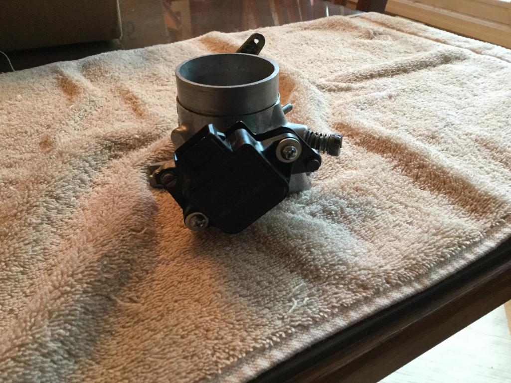
Posted by: Mblizzard Oct 16 2016, 03:42 PM
Also mounted the MicroSquirt and the relays to get ready for the actual wiring to start.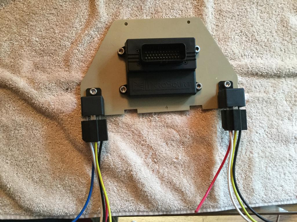
Posted by: McMark Oct 16 2016, 09:36 PM
My wiring harness connects to and uses the stock relay panel. It's got the two relays you need and access to them via the four pin FI connection. You can use standard spade connections, or the stock style four pin connector is available. I like your mounting board though.
Looks like you got it sorted out, but I forgot to mention the TPS can be spaced off the adapter plate (which is looks like you did), or you can trim the throttle shaft so everything sits flush.
Posted by: Mblizzard Oct 17 2016, 08:15 AM
My wiring harness connects to and uses the stock relay panel. It's got the two relays you need and access to them via the four pin FI connection. You can use standard spade connections, or the stock style four pin connector is available. I like your mounting board though.
Looks like you got it sorted out, but I forgot to mention the TPS can be spaced off the adapter plate (which is looks like you did), or you can trim the throttle shaft so everything sits flush.
McMark as others might want to look at a premade arrangement for the harness, could you post a picture of yours?
Posted by: McMark Oct 17 2016, 09:08 AM
Apparently I've never taken a picture of a completed harness...
I need to make another one anyway, so I'll do some documentation this time.
Posted by: Mblizzard Oct 17 2016, 09:15 AM
Apparently I've never taken a picture of a completed harness...
I need to make another one anyway, so I'll do some documentation this time.
Well there you go. After all of the help you have provided me (and many others) finally a good suggestion from the cheap seats.
Posted by: cgnj Oct 17 2016, 03:39 PM
As far as anyone recommending Mark. I never hear it over and over again in the same thread. You hear it once and the odd time a single person might concur...but that's it.
This thread has several direct "you need to buy from this guy", twice from you and both of those times after Mike had already bought his system from DIY Autotune. It also has a few more what I'll call indirect references.
Yes not all from you and you can't control what others say, but damn it gets annoying.
Ok I'm guilty, but that was for a cam position sensor only. I only know of a single source.
I like Mark, I have bought many things from him in the past. I don't promote him because I think it's called "guilding the lily".

I confirmed that you can't use 36-1 crank wheel mounted behind the fan with a stock AC pulley. Have you decided what to do about this issue?
Posted by: Mark Henry Oct 17 2016, 03:55 PM
Ok I'm guilty, but that was for a cam position sensor only. I only know of a single source.
No, you are not guilty, yours was pertinent information.
I have nothing against the Dub Shop, I was getting annoyed that others were going on and on even after the OP had already bought his system.
Posted by: Mblizzard Oct 17 2016, 04:13 PM
I confirmed that you can't use 36-1 crank wheel mounted behind the fan with a stock AC pulley. Have you decided what to do about this issue?
Thanks for the confirmation. It seemed that way. Not sure where to go. The dizzy should be the best option but I have to work it out a bit more.
Need to get the fuel part sorted first.
Posted by: crash914 Oct 17 2016, 05:19 PM
Damn, I was in Anacortes last Tuesday/Wednesday! would have bought you a beer..
WHAT!??!?
Everyone should ditch MicroSquirt so they can run stock low-impedance injectors? This is advice? MicroSquirt has SO MANY advantages in terms of simplicity for people who just want a simple D-Jet replacement. If you can't see those advantages, you're keeping yourself intentionally blind. Yes, an MS3 has way more advanced features than MicroSquirt. But as you said, "It's really easy to get lost in all the obscure details and overthink this stuff, making it over-complicated." So it seems to me that a small, weatherproof and fully functional ECU would be a step toward simplicity. You're pontificating on the benefits of MS3 because it can be modified and in the next breath promoting simplicity. Those are diametrically opposite. You can't promote both. YOU are letting your DubShop promotion job get in the way of actually helping people.
I have firsthand experience. MicroSquirt works. It does everything most people need for half the price. Please, take the challenge and explain to me how a normally aspirated 2056 needs a fucking MS3!
I was not clear in my response; sorry. The above response was actually meant for those who have yet to purchase an ECU. You can order it from wherever you buy it with the features you want so there's no need to mod it yourself.
The main advantage to MS3 is the resolution in tuning over any of the previous versions. Everything is pretty much built in already so the user just uses what they want and not what they don't.
MS3 for a 2056 is likely more than what most would need, however how many people stay with a 2056 over the life of their cars?? Many people I know tend to want to step up to a larger motor later on. That's where a system capable of more things like sequential fuel & spark become rather important. I run my system on a small street motor and on my race motor. Yes I don't need sequential fuel & spark on a 2056 with the cam that has, but it is important on the other motor I run in this car with the exact same system.
Over the last 5-7 years I have watched and read many threads from folks on this board who have problems getting their Microsquirt systems driving on the street and performing like they should. It's a perfectly capable system, but there are a lot less users of it and therefore less of a pool of knowledgeable people with successful conversions with which to draw experience from when problems arise. That's just not the case with MS2 or MS3.
Say what you will about myself being a "shill" for my friend. I really don't care what you all say about that. His systems/products work and work well and his after sale support is second to none, no matter who you are or where you live. Why would I not mention ANYONE with that reputation?? I don't give anyone any crap about pimping your services. Should I be??
Posted by: McMark Oct 17 2016, 05:52 PM
I have an AC pulley with magnets in it for a hall pickup. You could use this setup. Not as accurate as a VR sensor, but it works. It's what SDS uses on their setup. I build this pickup mount for an SDS install.
Attached image(s)
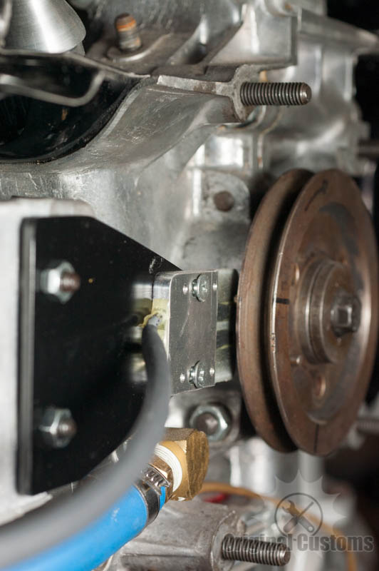
Posted by: Mblizzard Oct 18 2016, 06:21 AM
I have an AC pulley with magnets in it for a hall pickup. You could use this setup. Not as accurate as a VR sensor, but it works. It's what SDS uses on their setup. I build this pickup mount for an SDS install.
I like that.
Ok to be clear, I have learned just enough about all of this to be really dangerous so bear with me!
Would it not be just as easy to install something like this on the impeller?
Posted by: McMark Oct 18 2016, 07:06 AM
You could do that. 
Posted by: Mark Henry Oct 18 2016, 07:57 AM
Impeller would be a PITA because you have to be able to set the gap between the sensor and magnets.
My first SDS I just drew up some circles on sheet of aluminum, cut it out with a jigsaw, drilled it to bolt to the stock fan spacer washer. The sensor just bolted to the fan housing with a small mount I made.
Here's the link to my first install and it shows how I did the crank mount.
Yes I have been running programmable FI for a long time, longer than anyone on this board.
http://www.914world.com/bbs2/index.php?act=ST&f=2&t=5396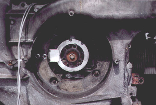
Posted by: Mblizzard Oct 18 2016, 08:21 AM
Impeller would be a PITA because you have to be able to set the gap between the sensor and magnets.
My first SDS I just drew up some circles on sheet of aluminum, cut it out with a jigsaw, drilled it to bolt to the stock fan spacer washer. The sensor just bolted to the fan housing with a small mount I made.
Here's the link to my first install and it shows how I did the crank mount.
Yes I have been running programmable FI for a long time, longer than anyone on this board.
http://www.914world.com/bbs2/index.php?act=ST&f=2&t=5396
I would think with the hole in the top of the impeller housing it would be easy to thread in the sensor and set it at the correct distance. Pretty much not going to need to set the timing from there after the install.
But I am just sitting here thinking not actually doing.
Posted by: Mark Henry Oct 18 2016, 01:58 PM
I would think with the hole in the top of the impeller housing it would be easy to thread in the sensor and set it at the correct distance. Pretty much not going to need to set the timing from there after the install.
But I am just sitting here thinking not actually doing.
I just mounted the fan shroud and checked the gap. Gap is not super critical, it's something like .025 to .060", the big one is you never want the magnets to hit the sensor. Once you are happy you red locktite all the screws (blue on the adjuster screws), install the fan and button it up. You should never have to adjust it again.
It took some time but it wasn't that hard to do. If I could find the mount I'd send it to you, but I changed it out several years ago.
Posted by: N_Jay Oct 18 2016, 02:27 PM
I would think with the hole in the top of the impeller housing it would be easy to thread in the sensor and set it at the correct distance. Pretty much not going to need to set the timing from there after the install.
But I am just sitting here thinking not actually doing.
That was my first thought. Looked like a easy win.
Guessing other know better.
Posted by: Mark Henry Oct 18 2016, 03:21 PM
I would think with the hole in the top of the impeller housing it would be easy to thread in the sensor and set it at the correct distance. Pretty much not going to need to set the timing from there after the install.
But I am just sitting here thinking not actually doing.
That was my first thought. Looked like a easy win.
Guessing other know better.
Nope...you need the timing hole, you have to set the initial timing with a strobe.
The ecu is good, but it can't guess where the timing is set the first time.
Once you enter/adjust the timing value, so that both the ECU and strobe is seeing say 10 degrees BTDC idle at the same time, then you never have to break out the strobe again.
Posted by: Mblizzard Oct 23 2016, 05:38 PM
Well some minor progress was made.
Finished the TPS wiring.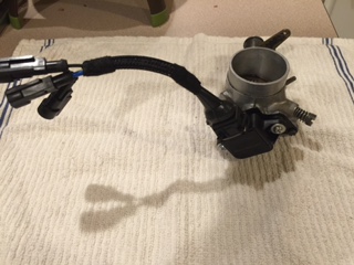
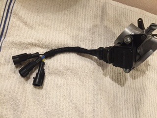
Came up with a pretty cool way to install the air temp sensor using the cold start valve.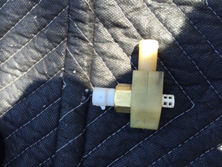
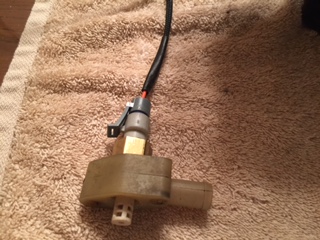
And made the injector harness.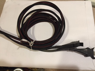
And made the resistor pack for the injectors.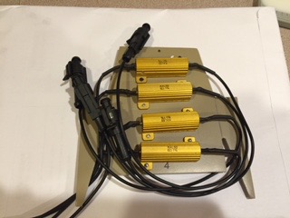
Attached image(s)
Posted by: Mblizzard Oct 31 2016, 09:06 AM
I was a complete slacker this weekend! Weather was great and my wife said lets enjoy the weekend together so I got nothing done!
Heading to Ukraine next weekend so the progress will be slowed considerable.
Posted by: McMark Nov 16 2016, 01:04 PM
My wiring harness connects to and uses the stock relay panel. It's got the two relays you need and access to them via the four pin FI connection. You can use standard spade connections, or the stock style four pin connector is available. I like your mounting board though.
Looks like you got it sorted out, but I forgot to mention the TPS can be spaced off the adapter plate (which is looks like you did), or you can trim the throttle shaft so everything sits flush.
McMark as others might want to look at a premade arrangement for the harness, could you post a picture of yours?
Found a picture Zach took of my harness and remembered this thread.
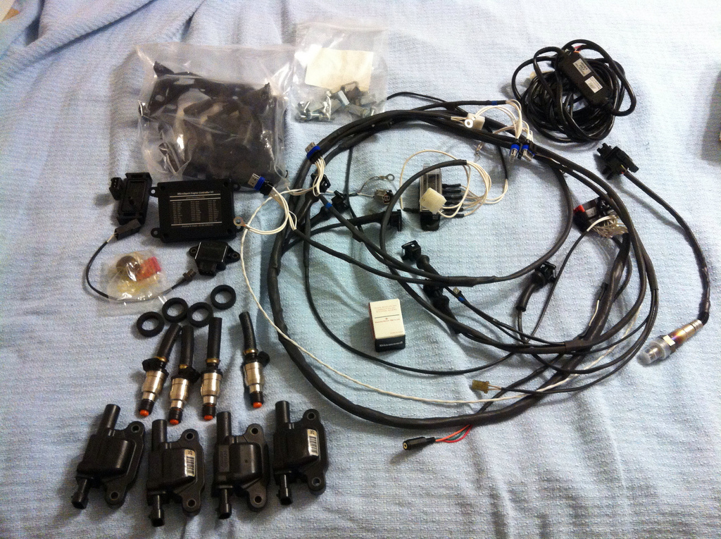
Posted by: Montreal914 Feb 5 2017, 11:03 PM
This was an interesting thread, any progress? Thank you.

Posted by: Mblizzard Feb 6 2017, 07:36 PM
A bit stalled due to time and work crunches. But will be turning back to it soon.
Posted by: Mblizzard May 7 2017, 05:05 PM
Ok so a few things have moved on so i am now returning to this!
Seems like I have all of my parts now as i just picked up a Idle Air control valve.
After rethinking a few things i decided to get rid of the low impeadance injectors and buy new high impeadance ones. Kind of blows my low dollar approach but it seems that if i was really going for a modern system then i might as well go all in.
Gone through some bench testing of the components and it seems like everything is measuring as it should. Temp gauges, TPS, MAP all seem to be working.
Wish I could easily use a sequential injector fire approach but seems like i will be using batch fire. Maybe with the modern feed back controls it wont be an issue.
Should have a free weekend next week and start the swap then.
As a question what is the best way to deal with the wires that are not being used for a fuel only appliacation?
Posted by: McMark May 8 2017, 05:40 AM
You'll never notice the difference between sequential injection an batch injection.
Posted by: Mblizzard May 8 2017, 01:24 PM
I am sure there are other places to get the high impedance injectors that will work with the stock injector hold downs but I happened to find them https://www.fiveomotorsport.com/a280-a380-high-impedance-hose-type-fuel-injectorif anyone else is looking for them.
Posted by: Mblizzard May 9 2017, 06:13 PM
You'll never notice the difference between sequential injection an batch injection.
At the risk of proving to the world just how big an idiot i am, what is the process for removing wires from the harness?
Posted by: Vacca Rabite May 9 2017, 07:14 PM
You'll never notice the difference between sequential injection an batch injection.
At the risk of proving to the world just how big an idiot i am, what is the process for removing wires from the harness?
gently cut off the shrink wrap around the wire harness.
isolate the wires that you want to remove.
the AmpSeal block unlocks at the front and rear. do some you tube research on how to seat and unseat wires in the Ampseal. It is easy to break the block at the locking tabs. Pull the wires out of the Ampseal. Rewrap the harness in heat shrink tube or wire harness wrap.
Zach
Posted by: Mblizzard May 14 2017, 07:07 PM
So but sure! Got done with the bench testing and strarted the install.
Removed old FI stuff. Installed air temperature sensor. 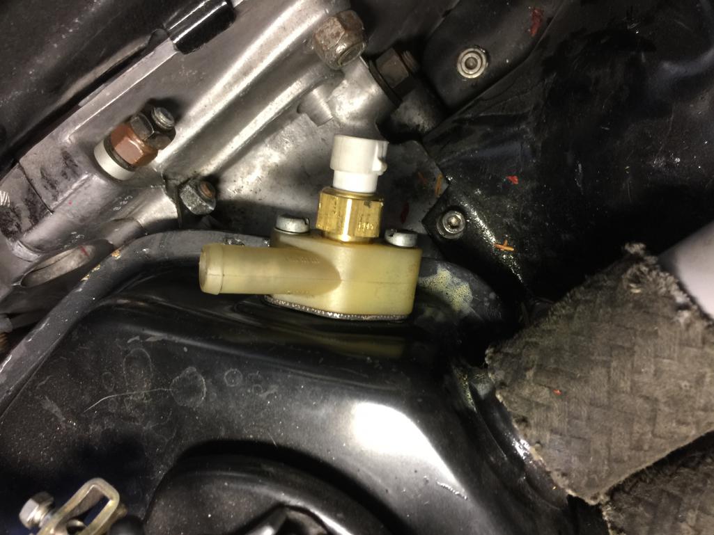
Got the new throttle body installed. 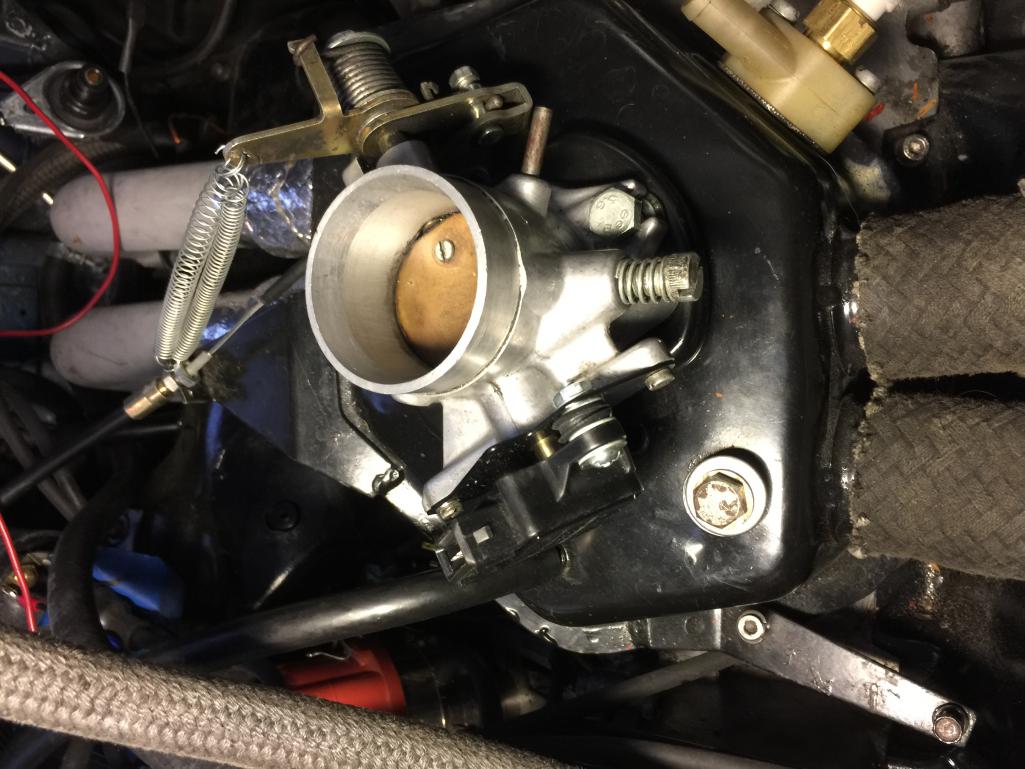
Not there yet. But will keep working. Also decided to add Bluetooth to the system so that I can run EFI Analytics Shadow Dash.
Posted by: Mblizzard May 15 2017, 06:02 PM
Got the Bluetooth connection working with Shadowdash. Using cheap $90 Android tablet with EFI Bluetooth connector. Flawless so far. 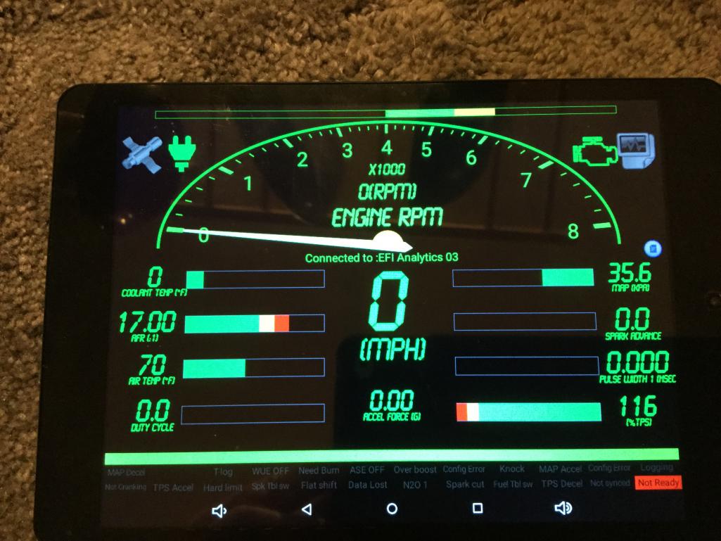
Posted by: Mblizzard May 15 2017, 06:27 PM
Oh yea got new high impeadance injectors in today. Injectors, new seals, and connectors $75 each. Not too bad. 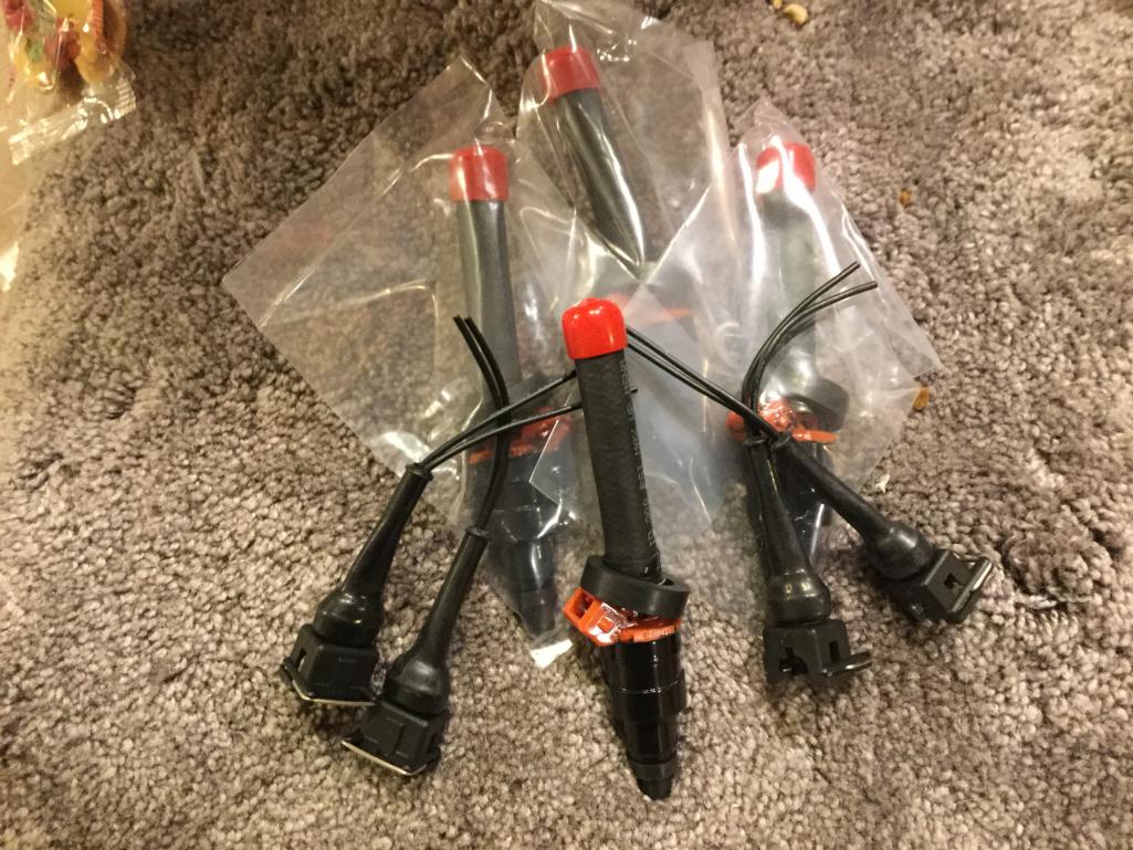
Posted by: Vacca Rabite May 15 2017, 07:16 PM
Got the Bluetooth connection working with Shadowdash. Using cheap $90 Android tablet with EFI Bluetooth connector. Flawless so far.
What bluetooth connector did you use?
How are you powering it?
Pics please!
Zach
Posted by: Mblizzard May 16 2017, 08:26 AM
Got the Bluetooth connection working with Shadowdash. Using cheap $90 Android tablet with EFI Bluetooth connector. Flawless so far.
What bluetooth connector did you use?
How are you powering it?
Pics please!
Zach
Using the EFI Battery Powered RS232 Bluetooth Adapter (MicroSquirt). It has a battery option and can be run on standard 5V from a mini USB connector or its internal battery.
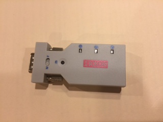
Planning on adding a cheap USB voltage converter and hardwiring it to switched power.
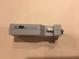
Has switch to let it run on battery or external power. Pretty neat since the Microsquirt does not provide power.
Posted by: Philip W. May 16 2017, 08:35 AM
Mike,
id be curious to see what the whole process of conversion ends up costing. I know you are doingmost of this work. With all the issues we have with maintaining out d-jet systems due to MPS issues etc, I'm surprised no one has ever put together a plug and play system, ecu with harness, connectors to the relay board etc.
Posted by: Mblizzard May 16 2017, 09:03 AM
Mike,
id be curious to see what the whole process of conversion ends up costing. I know you are doing most of this work. With all the issues we have with maintaining out d-jet systems due to MPS issues etc, I'm surprised no one has ever put together a plug and play system, ecu with harness, connectors to the relay board etc.
I believe http://www.914world.com/bbs2/index.php?showtopic=295825&st=120# of Original Customs has the closest set up that is out there. I am not sure if the ECU is already programed or not on his version.
But I think a Fuel only options that works could be purchased as well.
Before I let things get away from me I had everything ready to go for just over $650. This used a number of the stock components like injectors, CHT, AAR, and other things I cant remember.
After the $650, new injectors, Bluetooth, Android tablet, GPS, modern idle air control valve, and such pushed it to $1000 range. But these are toys not a must for the conversion.
I don't have it running yet but with the Auto Tune feature of Tuner Studio I am hopping I don't have to spend too much time programing settings
Posted by: Philip W. May 16 2017, 09:35 AM
cool, thanks for info- looking forward to seeing this in September- I have an occasional buck I cant explain that comes when driving only , not under heavy load , usually cruising or slight acceleration- not the same as one I had due to the tps before I replaced it.- and it bugs me enough that I will try one or two more thinks before deciding to go this route myself, so that's why I ask, trying to get an idea for what I would be into if I went this route too. I do have a local shop, Bob Woodman tires that has lots of experience with these in the 911 community so if I need help I know its available but im a glutton for punishment and would attempt to do it myself first
Posted by: Racer Chris May 16 2017, 09:43 AM
I have an occasional buck I cant explain that comes when driving only , not under heavy load , usually cruising or slight acceleration-
Slightly too lean will do this. A small adjustment to the MPS to richen the mixture might eliminate your light throttle hesitation.
Posted by: Mblizzard May 16 2017, 09:51 AM
I have an occasional buck I cant explain that comes when driving only , not under heavy load , usually cruising or slight acceleration-
Slightly too lean will do this. A small adjustment to the MPS to richen the mixture might eliminate your light throttle hesitation.
If you don't have an AFR gauge installed yet that can help confirm what Chris was saying.
I had that for a while and eventually was able to get it smoothed out. But as I adjusted fro one thing it always seemed that something else got out of whack so I decided to quit chasing.
Posted by: Mblizzard May 16 2017, 07:37 PM
Slow,but just a little bit each day. New high impeadance injectors prepped for install. 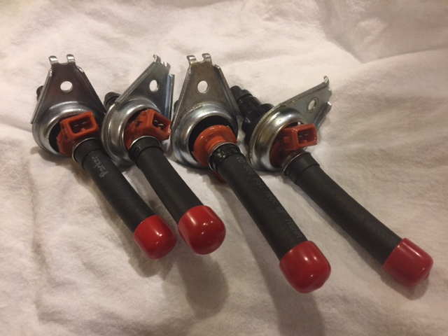
Posted by: Montreal914 May 16 2017, 09:33 PM
I like it!
Posted by: Mblizzard May 17 2017, 04:12 AM
VW Passat idle air control valve for cold starts. Hopefully better than the 40 year old Auxiliary air valve. At this one can be controlled. 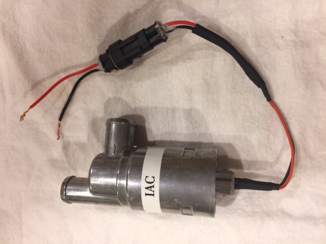
Posted by: Philip W. May 17 2017, 06:54 AM
VW Passat idle air control valve for cold starts. Hopefully better than the 40 year old Auxiliary air valve. At this one can be controlled.
interesting!, I have not seen this discussed before- could this be used with a d-jet application as well??
Posted by: Philip W. May 17 2017, 07:03 AM
I have an occasional buck I cant explain that comes when driving only , not under heavy load , usually cruising or slight acceleration-
Slightly too lean will do this. A small adjustment to the MPS to richen the mixture might eliminate your light throttle hesitation.
If you don't have an AFR gauge installed yet that can help confirm what Chris was saying.
I had that for a while and eventually was able to get it smoothed out. But as I adjusted fro one thing it always seemed that something else got out of whack so I decided to quit chasing.
thanks for input- sorry for the highjack-
yes I have a AF meter installed, and I have been playing around with it for some time, I have now tuned 2 MPS that are pretty dialed in- here is what I have observed, just this week since weather has been perfect ive been driving the car to work which is a 25 mile , 30 minute commute- the AFR reads about 12.7-13.4 on cruising now, but when the hesitation hits the A/F meter reads suddenly more rich, like a drop in the gauge reading to a 9.5-10, and its just for a split second. my first thought was TPS but this board is new(once replaced it got rid of the bucking on acceleration at 3000rpm that is common with a bad board- I have zero issue on hard acceleration) so then my next thought was grounding but that would cut out the injector firing and lean it not make it more rich right?? I defer to those with more experience playing around with this.
like I said , sorry for the highjack but I know you played around with yours for a long time before going to this system,- but I am watching close to your progress and very interested in seeing how the system comes together- I think you are going to really like the ability to program on the go with a system like this!!!
so please keep updating us with all the exciting and boring details! LOTS OF PICS!
Posted by: Mblizzard May 17 2017, 07:44 AM
VW Passat idle air control valve for cold starts. Hopefully better than the 40 year old Auxiliary air valve. At this one can be controlled.
interesting!, I have not seen this discussed before- could this be used with a d-jet application as well??
No way to control it on D-Jet. It uses pulse width modulation to control the opening something that the D-Jet just cant do. I did play with using a normally close electrically controlled valve and a thermal switch to replace the AAV. worked pretty well but it was and off or on approach so there was no gradual transition between open and closed.
Posted by: Vacca Rabite May 21 2017, 05:27 PM
VW Passat idle air control valve for cold starts. Hopefully better than the 40 year old Auxiliary air valve. At this one can be controlled.
This is exactly what I need to add for my car.
Zach
Posted by: Mblizzard May 21 2017, 06:49 PM
Big day! More wires in the car now than on the bench!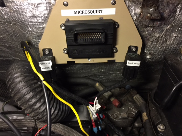
New injectors installed and wired!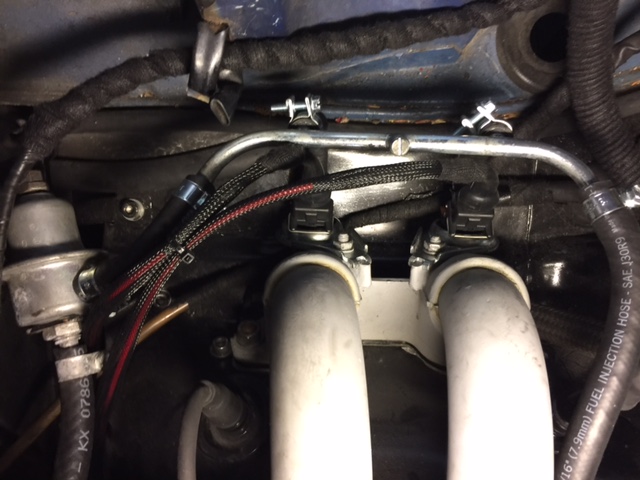
Placed idle air valve in an out of the way but close location.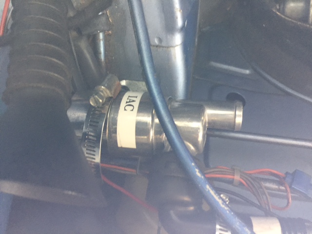
Getting closer. A few more days of working and should be ready to start it!
Attached image(s)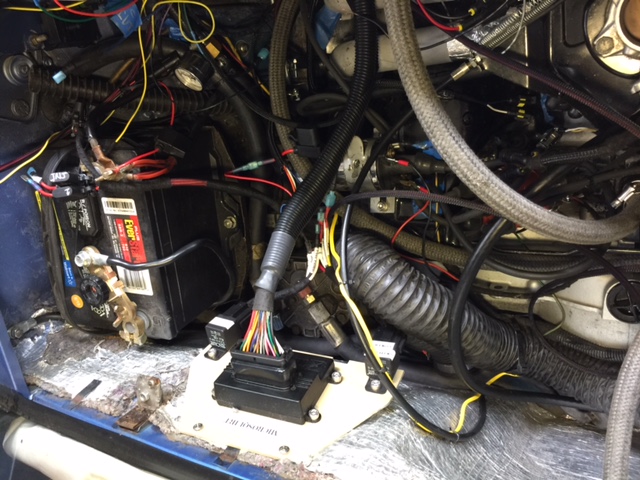
Posted by: Mblizzard May 21 2017, 07:00 PM
VW Passat idle air control valve for cold starts. Hopefully better than the 40 year old Auxiliary air valve. At this one can be controlled.
This is exactly what I need to add for my car.
Zach
Got it for $28 off evil bay. I can get you the link.
Posted by: Mblizzard May 21 2017, 07:42 PM
I had a question about changing to new high impeadance injectors. I never checked the old ones but I am sure of my flow rates and that the injectors are matched. May not make ny difference but i a;ways felt i had one injector that caused a cylinder to run rich. Made it hard to work with the D-jet limitations.
Working from a matched set now. 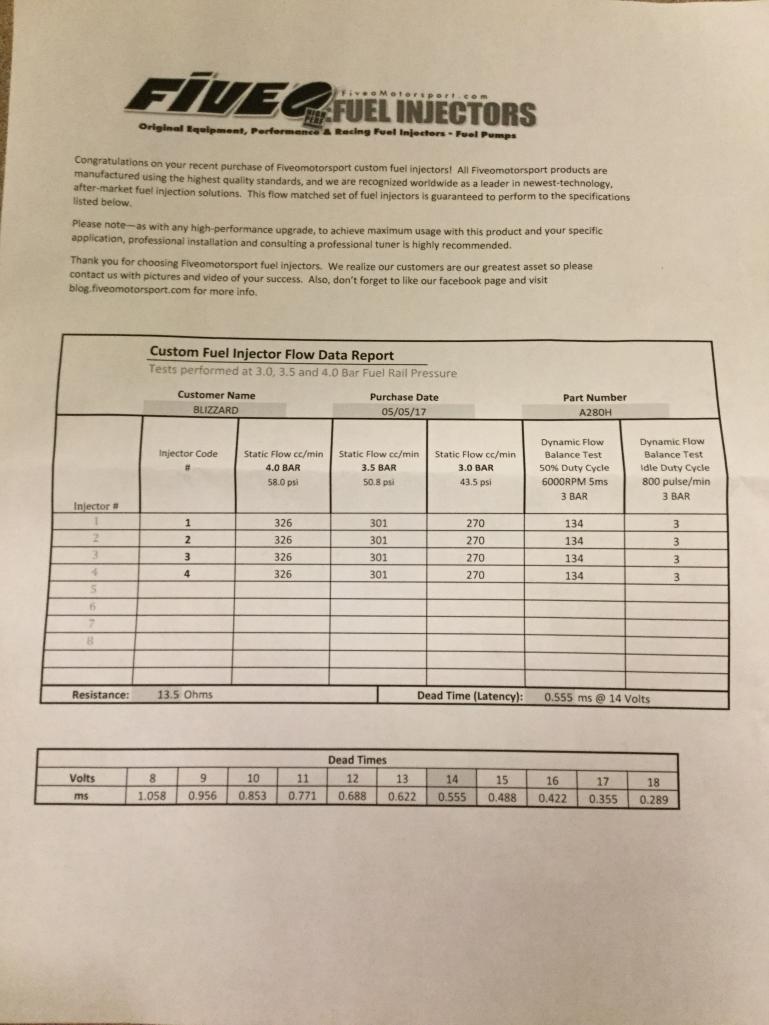
Posted by: crash914 May 22 2017, 04:01 AM
You most likely will need to adjust your fuel pressure. Stock D-jet systems used 2 bar fuel pressure. If you look at your flow sheet, minimum flow was 3 bar. This might not make any difference, except for the flow pattern of the spray at 2 bar. (Volume however, is completely different and will require tuning after any change)
Posted by: Mblizzard May 22 2017, 06:17 AM
You most likely will need to adjust your fuel pressure. Stock D-jet systems used 2 bar fuel pressure. If you look at your flow sheet, minimum flow was 3 bar. This might not make any difference, except for the flow pattern of the spray at 2 bar. (Volume however, is completely different and will require tuning after any change)
Yep already adjusted. It seems like the stock fuel pressure regulator tops out at about 50 lbs. I am at about 43 lbs. now so I will used that as the starting point.
Also you get some good info for programing the fuel set up regarding
dead times. Not sure how much difference it makes but the software suggested a dead time of 0.9 ms at 13.2 volts. Looks like I have 0.622 ms.
Posted by: Mblizzard May 22 2017, 01:52 PM
VW Passat idle air control valve for cold starts. Hopefully better than the 40 year old Auxiliary air valve. At this one can be controlled.
This is exactly what I need to add for my car.
Zach
Got it for $28 off evil bay. I can get you the link.
Here is the http://www.ebay.com/itm/322349484033?_trksid=p2057872.m2749.l2649&ssPageName=STRK%3AMEBIDX%3AIT.
Posted by: Vacca Rabite May 25 2017, 10:53 AM
VW Passat idle air control valve for cold starts. Hopefully better than the 40 year old Auxiliary air valve. At this one can be controlled.
This is exactly what I need to add for my car.
Zach
Got it for $28 off evil bay. I can get you the link.
Thanks!
Zach
Posted by: Mblizzard May 25 2017, 07:45 PM
Not a lot of progress. Checking wires and settings. Hope tô Starr this weekend.
Posted by: Vacca Rabite May 26 2017, 07:04 AM
VW Passat idle air control valve for cold starts. Hopefully better than the 40 year old Auxiliary air valve. At this one can be controlled.
This is exactly what I need to add for my car.
Zach
Got it for $28 off evil bay. I can get you the link.
Thanks
Zach
Does the connector on your IAC have only 2 prongs and 2 wires or 3 prongs and you only used 2 wires?
Zach
Posted by: Mblizzard May 26 2017, 09:00 AM
VW Passat idle air control valve for cold starts. Hopefully better than the 40 year old Auxiliary air valve. At this one can be controlled.
This is exactly what I need to add for my car.
Zach
Got it for $28 off evil bay. I can get you the link.
Thanks
Zach
Does the connector on your IAC have only 2 prongs and 2 wires or 3 prongs and you only used 2 wires?
Zach
It is a 2 wire. Forgot to buy the connector so I had to make one. Seems to work well using the PWM method. I have just verified the operation and have not verified the settings required to keep the car running.
Posted by: Mblizzard May 27 2017, 07:22 PM
Well so close yet nothing. Seems like I have about everything wired up but can't get it to run. Seems like somehow I am failing to be able to trigger the injectors off the coil. No fuel!
Stumped at this point.
Posted by: McMark May 28 2017, 07:21 AM
Triggering off the coil sucks. 
Posted by: Mblizzard May 28 2017, 08:19 PM
Ok had is give up on the coil trigger. 
But I have a 123 electronic dizzy with electronic trigger points. So I thought why not pull a signal off of the electronic points. So I removed all of the coil set up and used the VR channel to pick up a tach signal. And it worked. So it is not perfect as I just used the basic trigger method and I think I have some adjustments to do to smooth it out. But it started and runs. 
Running rich and erratic on the tach signal but running.
Any thoughts on the tigger angle offset! I thin that the tach is reading high as it may be seeing double the pluses at the dizzy as it would see at the crank.
Posted by: McMark May 29 2017, 06:04 AM
The offset angle won't really matter while you're not controlling ignition with the MS. Injector spray timing isn't anywhere close to critical. If it's a few milliseconds off the fuel will essentially just wait in the port for the valve to open.
So the electronic points is essentially a TDC trigger, but it doesn't matter if TDC in reality is sync'd with TDC in the computer. That's what offset angle is for, to fine tune (or sync) the computer and the engine. When you're controlling ignition from the MS, it's crititcally important that TDC be in sync, so when the computer is trying to provide 12degrees of advance, that's actually happening at 12 degrees BTDC.
Fuel doesn't really care.
But if you ever try to run ignition, none of this will work.
Posted by: Mblizzard May 29 2017, 10:34 AM
The offset angle won't really matter while you're not controlling ignition with the MS. Injector spray timing isn't anywhere close to critical. If it's a few milliseconds off the fuel will essentially just wait in the port for the valve to open.
So the electronic points is essentially a TDC trigger, but it doesn't matter if TDC in reality is sync'd with TDC in the computer. That's what offset angle is for, to fine tune (or sync) the computer and the engine. When you're controlling ignition from the MS, it's crititcally important that TDC be in sync, so when the computer is trying to provide 12degrees of advance, that's actually happening at 12 degrees BTDC.
Fuel doesn't really care.
But if you ever try to run ignition, none of this will work.
Seem to be getting double,tach signal out of trigger points. Any way tom1/2 that in the software.
Posted by: McMark May 29 2017, 01:50 PM
Check the dual/multi spark options under ignition. You might have luck setting it to Single Cam Wheel Input.
Attached image(s)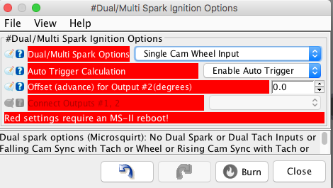
Posted by: Mblizzard May 29 2017, 06:10 PM
Check the dual/multi spark options under ignition. You might have luck setting it to Single Cam Wheel Input.
I am using Tunner Studios and don't see this option.
As a back up get me a quote for a trigger wheel and sensor as I am tired of screwing with this.
Posted by: Vacca Rabite May 29 2017, 09:53 PM
Did you ever hardwire the bluetooth adapter in? How are you powering it, since the Microsquirt serial cable does not send power?
Zach
Posted by: McMark May 30 2017, 06:53 AM
It's under the Ignition Setup -> Dual/Multi Spark Options. You are running the MicroSquirt firmware, right? MSII firmware has different menus.
http://www.914world.com/bbs2/index.php?showtopic=97550
Posted by: Mblizzard May 30 2017, 08:29 AM
Did you ever hardwire the bluetooth adapter in? How are you powering it, since the Microsquirt serial cable does not send power?
Zach
Pretty straight forward. Used a cheap 12V to 5V Power Supply with Mini USB Interface. About $8 Amazon.
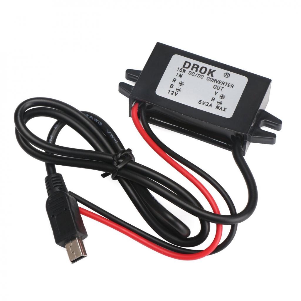
Ran the standard cable to center consul and ready to go.
Posted by: Mblizzard May 30 2017, 08:34 AM
It's under the Ignition Setup -> Dual/Multi Spark Options. You are running the MicroSquirt firmware, right? MSII firmware has different menus.
http://www.914world.com/bbs2/index.php?showtopic=97550
Well taking this approach will require an engine drop
Not what I want to do. There has to be some way to make this coil approach work. Going to work with the coil a bit more to see if I can get something working.
What I really need is a way to get the trigger point signal into the ECU.
Posted by: McMark May 30 2017, 09:25 AM
That would be 1/4 engine speed.
Posted by: Mblizzard May 30 2017, 09:31 AM
That would be 1/4 engine speed.
I am thinking 1/2. The signal is separated into 2 banks and I only will use one of them since it is batch fire.
Posted by: McMark May 30 2017, 09:41 AM
Yeah, you're right. If you were trying to count 4-trigger events, it would be 1/4 speed. But really you just care about 1 single TDC marker. You could get a bare hall effect sensor and mount that on one side of the trigger point plate. It would take some trial and error, but it should be doable. The cam for the trigger points (on the dist. shaft) is not the ideal shape because the ramps are smooth.
Attached image(s)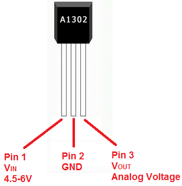
Posted by: McMark May 30 2017, 09:44 AM
Actually, you may be able to trigger it off on one side of the trigger points.
Posted by: timothy_nd28 May 30 2017, 10:27 AM
I'm not familiar with the 123 distributor or the megasquirt setup so I can be totally wrong with any advice. It's possible that the your microsquirt isn't hearing the signal from your dizzy. You could try a 10k ohm pull up resistor to see if that helps.
Posted by: Mblizzard May 30 2017, 12:07 PM
In which configuration are you talking about? Firing from the coil or the trigger points? Attached is some info I have on dizzy. 123PORSCHE4.pdf ( 317.59k )
Number of downloads: 53
123PORSCHE4.pdf ( 317.59k )
Number of downloads: 53
It is clear that the signal I get off the trigger point is very noisy and the rpm are erratic. I tried a variable resistor to 5K with no noticeable difference. Got some resistors coming to try other values.
I think I found a way in the software to tell the ECU more about the system. Going to see if it will allow the a Non missing tooth on cam set up with a Single tooth on
crank or two opposite teeth on cam the 2 opposite teeth should mimic the trigger points pretty well.
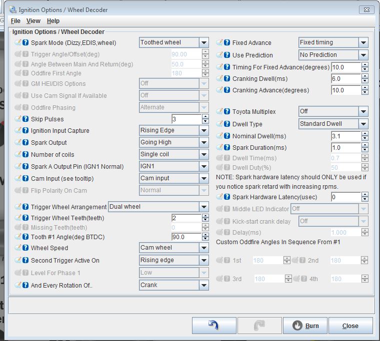
Attached File(s)
123PORSCHE4.pdf ( 317.59k )
Number of downloads: 78
Posted by: timothy_nd28 May 30 2017, 12:20 PM
Trigger points
Posted by: Mblizzard May 30 2017, 01:05 PM
Trigger points
Did try the variable resistor but only went to 5K. Also not sure if this should be pull up or pull down.
Posted by: Mblizzard May 30 2017, 01:07 PM
Yeah, you're right. If you were trying to count 4-trigger events, it would be 1/4 speed. But really you just care about 1 single TDC marker. You could get a bare hall effect sensor and mount that on one side of the trigger point plate. It would take some trial and error, but it should be doable. The cam for the trigger points (on the dist. shaft) is not the ideal shape because the ramps are smooth.
No cam in the dizzy. Trigger points replaced with electronic out put. I think I am getting the analog voltage out signal from the trigger points but I am not sure how to tell the EWCU what it is seeing.
Posted by: timothy_nd28 May 30 2017, 02:25 PM
Looks like this 123 dizzy is a drop in replacement for the Djet as it has 2 wires for the fuel trigger points. The two wires seem to go to each fuel injector bank respectively at the ECU. The manual says to connect to pins 1 and 3 at the bosch FI trigger connector, since it's missing the third wire, I assume that this module is supplying its own ground.
With the above said, I'm assuming that this dizzy has an internal optoisolator that is triggering a switch which is independent from the rest of the ignition. I think these two wires are pulling to ground in a wig wag pattern because the OEM setup had 2 cam lobes that would fire a set of injectors independently from each other.
If you wired these two wires coming from the dizzy together as part of the whole circuit, the circuit would never complete because one contact would pull to ground as the other contact would open to infinity, thus a open circuit that the microsquirt would never see.
On a napkin, draw a sketch on how you had this wired previously. This is a good break from the biochem studying
Posted by: McMark May 30 2017, 02:44 PM
Yeah, that's MS2Extra Firmware.
Another point on the MS learning curve. Each firmware makes TunerStudio look completely different. So unless you're running the same firmware, comparing notes is useless. I haven't played with MS2E much, so I'm not familiar with all the settings.
Posted by: Mblizzard May 30 2017, 02:56 PM
Looks like this 123 dizzy is a drop in replacement for the Djet as it has 2 wires for the fuel trigger points. The two wires seem to go to each fuel injector bank respectively at the ECU. The manual says to connect to pins 1 and 3 at the bosch FI trigger connector, since it's missing the third wire, I assume that this module is supplying its own ground.
With the above said, I'm assuming that this dizzy has an internal optoisolator that is triggering a switch which is independent from the rest of the ignition. I think these two wires are pulling to ground in a wig wag pattern because the OEM setup had 2 cam lobes that would fire a set of injectors independently from each other.
If you wired these two wires coming from the dizzy together as part of the whole circuit, the circuit would never complete because one contact would pull to ground as the other contact would open to infinity, thus a open circuit that the microsquirt would never see.
On a napkin, draw a sketch on how you had this wired previously. This is a good break from the biochem studying
Yep nothing more boring than double-reciprocal plots (Lineweaver-Burk) for enzyme kinetics.
As you noted there is only one out wire from the Dizzy. I assumed the power coming in was the 12V being supplied to the dizzy from the + side of coil. So I put in the initial 1K pull up as shown with out any impact and it did not change going to 5K.
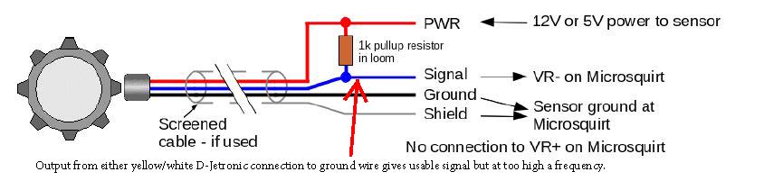
The ground shown in the figure is not there from the dizzy. The ECU wants all of the sensors to use a common sensor ground which is isolated from the other common ground to reduce noise. No way to tap that so this circuit is bound to have some noise.
The attached graph shows the RPM going from 3K to 0 in just few ms. The dash showed only about 1.5K so it seems doubled.
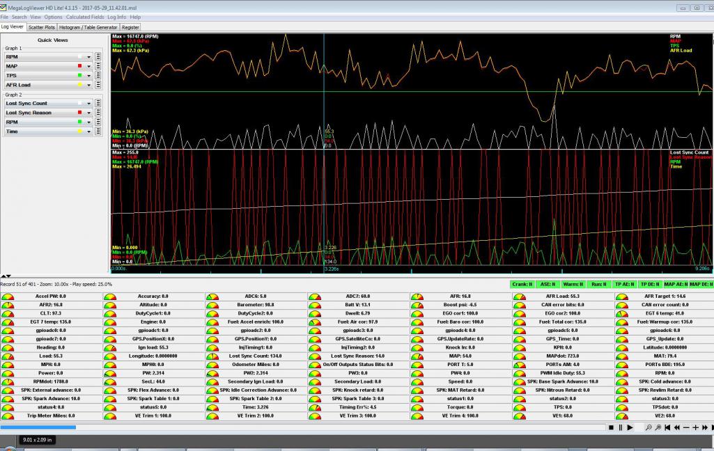
Posted by: McMark May 30 2017, 03:10 PM
It does NOT like that. See all those red Lost Sync peaks? That's your ECU resetting -- 255 times during your datalog! 
Posted by: timothy_nd28 May 30 2017, 03:20 PM
Engine ground would be a problem. If you wired the pull up resistor as shown, then all should be good but 1K ohm seems pretty low. Which color wire did you choose, yellow or white?
I'm sure you could dial this in with time and patience, but I think a VR with a good shielded cable is the better way to go. And if you go that route, might as well ditch the dizzy and do the coil pack dealy.
Posted by: Mblizzard May 30 2017, 03:42 PM
Engine ground would be a problem. If you wired the pull up resistor as shown, then all should be good but 1K ohm seems pretty low. Which color wire did you choose, yellow or white?
I'm sure you could dial this in with time and patience, but I think a VR with a good shielded cable is the better way to go. And if you go that route, might as well ditch the dizzy and do the coil pack dealy.
The VR is in the future but I wanted to do this some what low cost to prove it was possible.
Tried both. Yellow first
Posted by: Dtjaden May 30 2017, 09:29 PM
Engine ground would be a problem. If you wired the pull up resistor as shown, then all should be good but 1K ohm seems pretty low. Which color wire did you choose, yellow or white?
I'm sure you could dial this in with time and patience, but I think a VR with a good shielded cable is the better way to go. And if you go that route, might as well ditch the dizzy and do the coil pack dealy.
The VR is in the future but I wanted to do this some what low cost to prove it was possible.
Tried both. Yellow first
This is a kind of off-the-wall option. You could try using a Tach-Adapt box to regenerate a reliable square wave signal.
http://www.ashlocktech.com/
The Tach-Adapt is usually used to generate a coil like signal from systems that no longer use distributor/coil systems it it also has the option to do the opposite create low voltage square wave signal that should make the MS somewhat happy.
That being said, in one day, if you have someone to help, you can drop the engine, install a 36-1 crank wheel and hall or vr sensor and reinstall the engine. This would be the right way to solve the problem.
Posted by: timothy_nd28 May 30 2017, 10:23 PM
I'm totally with you, it's neat to try things outside the box. Triggering the MS from the ignition coil is extremely noisy, lots of ringing going on. I'm sure the MS is perfectly fine with inputs of the Hall or VR signals, but does it have built in filters to shape signals straight from the - terminal of the ignition coil?
Something is funky with the signal from 123 dizzy FI trigger outputs. Consider this as a not so quick test. Reinstall the original distributor and with 2 jumper wires, wire the MS to the distributors old school FI points. You may even have a setting for a reed style switch somewhere in the setup. If so, you wouldn't need any pull up resistors. It would be interesting to see the signal from the old school FI points vs the 123 electronic trigger points.
Posted by: Mblizzard May 31 2017, 02:16 AM
I'm totally with you, it's neat to try things outside the box. Triggering the MS from the ignition coil is extremely noisy, lots of ringing going on. I'm sure the MS is perfectly fine with inputs of the Hall or VR signals, but does it have built in filters to shape signals straight from the - terminal of the ignition coil?
Something is funky with the signal from 123 dizzy FI trigger outputs. Consider this as a not so quick test. Reinstall the original distributor and with 2 jumper wires, wire the MS to the distributors old school FI points. You may even have a setting for a reed style switch somewhere in the setup. If so, you wouldn't need any pull up resistors. It would be interesting to see the signal from the old school FI points vs the 123 electronic trigger points.
Don't have the old one anymore? Got this from Dizzy manufacturer
We produce very strange signal on the white and yellow wires.
Just good enough for the D-Jetronic system, but not suitable for anything else.
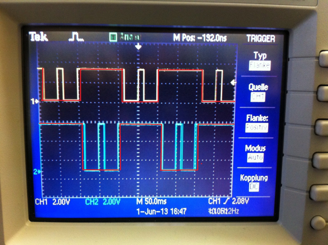
This seems to be what I see in the data logging. And account for the extra pulses. Any thoughts on conditioning? It seems if we could remove the second pulse inside the Square wave it would be perfect.
Posted by: timothy_nd28 May 31 2017, 09:08 AM
Strange but a very cool waveform. As the dizzy pulls each bank to ground it releases then hits it again, kinda like a double tap. I wonder why they are doing that for.
Shaping that odd waveform is indeed possible but not very practical. It would be far easier to use the signal from the old distributors FI triggers or buying the VR and trigger wheel kit. Alternatively, my circuit for your LED controller does condition the signal from the ignition coil. I could modify your controller so it has a 5 volt pulse output?
Posted by: Vacca Rabite May 31 2017, 01:21 PM
I highly suggest getting the crank toothed wheel.
You can take the doghouse off with the engine still in the car - I've done it. It isn't a ton of fun, but I have done it.
I got the VW air valve, and am looking forward to wiring it in on my car.
How are you getting the ECU to control it?
Zach
Posted by: Mblizzard May 31 2017, 03:48 PM
I highly suggest getting the crank toothed wheel.
You can take the doghouse off with the engine still in the car - I've done it. It isn't a ton of fun, but I have done it.
I got the VW air valve, and am looking forward to wiring it in on my car.
How are you getting the ECU to control it?
Zach
FIDLE using PWM was able to do the testing in the test part of tuner studio.
Will have to pull engine I have AC.
Posted by: Mblizzard May 31 2017, 03:54 PM
Going to still work the coil option but ordered the Orginal Customs trigger wheel just to be sure.
Just wish it came with free installation. I will buy the beer McMark!
Posted by: McMark Jun 1 2017, 06:25 AM
Sure, when will you be here and what kinda beer are you bringing?

Posted by: Mblizzard Jun 1 2017, 01:24 PM
Sure, when will you be here and what kinda beer are you bringing?
Love your free offer but the transportation might be a bit steep!
I essentially think I will just drop everything down and do the switch quickly. But I told my self that I would get a new AC compressor installed on the next drop $$$$$.
Have to find a York to Sanden adaptor plate. I am sure you have that as well?
Posted by: poorsche914 Jun 1 2017, 04:13 PM
If you would like to borrow my stock Djet distributor, let me know.
Posted by: Mblizzard Jun 5 2017, 08:17 AM
Well kind of in a holding pattern.
Waiting to see if DIY Auto Tune can offer any guidance on the coil trigger method but I am not sure it will work. Not sure why not but the ECU just wont see the signal from the coil and fire the injectors. While it is likely operator error, it is disappointing that this does not work smoothly. Seems like a very simple method but I get nothing.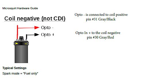
Ordered trigger wheel from McMark. Was planning on going to this at some point but the reality is that an engine drop will be required. But I am not sure how much room I will have for the sensor mounting with my current AC bracket. 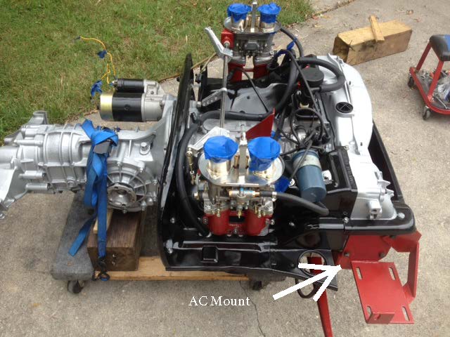
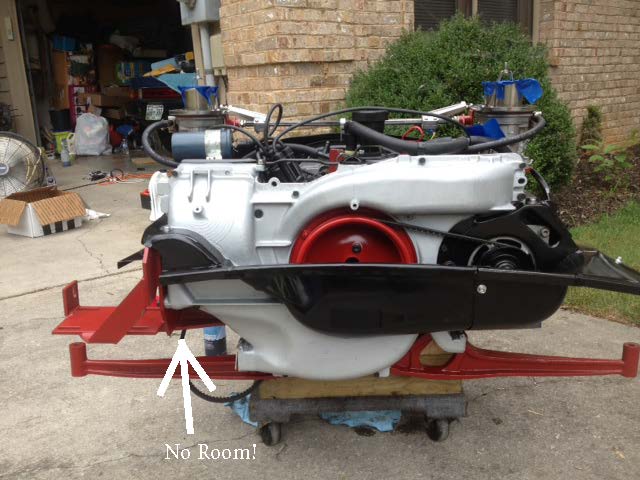
Also going to have to se if I can work out the trigger wheel/ AC pulley conflict.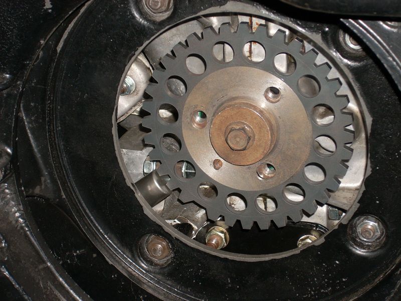
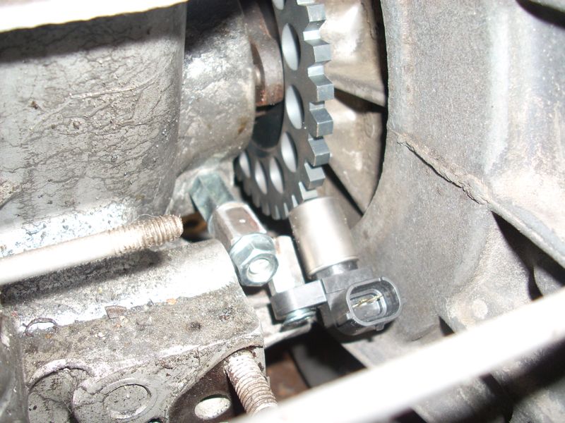
Little room left for the AC pulley. 
Posted by: timothy_nd28 Jun 6 2017, 06:10 PM
Doug (dlee6204) makes a neat bracket that mounts the sanden compressor on top. I bought his pulley adapter for this conversion but have decided to go a different route, it's all yours if you want it.
Posted by: Dave_Darling Jun 6 2017, 06:31 PM
For a York-Sanden adapter plate, the folks that make the Kuehl Air conversion for he 911 have something that works in that application. Heavy duty stuff.
--DD
Posted by: Vacca Rabite Jun 8 2017, 07:08 AM
My air valve came in today. What style connectors did you use to connect the wiring?
Zach
Posted by: McMark Jun 8 2017, 07:18 AM
Zach
If it's the 'bosch' style, I have connectors and pins.
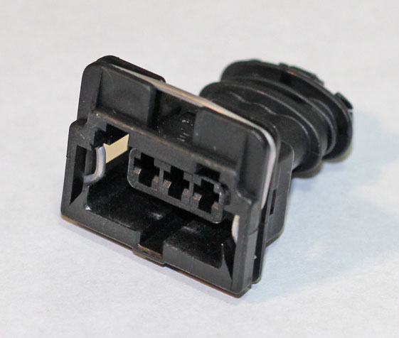
Posted by: Mblizzard Jun 8 2017, 09:01 AM
My air valve came in today. What style connectors did you use to connect the wiring?
Zach
I did not have the connector but I used just the small 2.8 mm https://smile.amazon.com/gp/product/B00OKCEANM/ref=oh_aui_detailpage_o07_s00?ie=UTF8&psc=1 from Amazon. .
Posted by: McMark Jun 8 2017, 11:31 AM
Ahh, the 2pin Bosch connector. I'll throw one in with your VR sensor, Mike. (Shipping today...  )
)
Zach, I'll send one your way too, with a couple AMP35 pins.
Posted by: Mblizzard Jun 8 2017, 06:10 PM
Ok so after working with DIY AutoTune it seems I may have an issue with my ECU. This could be causing my ECU to not pick up the signal from the Coil. So an engine drop may not be looming.
But I am still expecting that I will have to drop the engine just because.
Posted by: Mblizzard Jun 8 2017, 06:11 PM
Ahh, the 2pin Bosch connector. I'll throw one in with your VR sensor, Mike. (Shipping today...
)Zach, I'll send one your way too, with a couple AMP35 pins.
This is why I love the World and the great vendors we have.
Posted by: Mblizzard Jun 9 2017, 12:04 PM
Houston we have a problem!
After working with the guys at DIY Autotune, it seems like I may have a hardware problem on the board.
Resistor R20 should measure about 680 ohms. Actually has 681 printed on it.
Measured resistance? 0 ohms!
Of course this makes sense as R20 is in the Option +/- circuit which should give me a tach signal which I never saw out of the system once. 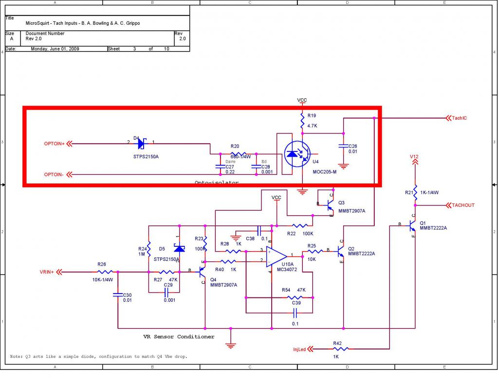
Waiting on feedback to see how to address.
Feel pretty good that I did the wiring correctly. The diode should have protected the circuit if it was reversed. But I am not a circuit guy.
Not sure this is a "user replaceable part." At least for this user.
Posted by: timothy_nd28 Jun 9 2017, 01:43 PM
That circuit is weak for filtering the noisy flyback high voltage from the ignition coil. You will have dropped signals at higher RPMs. I strongly recommend aborting on the OPTOIN - and OPTOIN + nonsense circuit and going with the safer trigger wheel route and don't look back.
If you insist on making this work, you should replaced that resistor with a higher wattage and either buy or make a circuit to better shape and condition that noisy incoming signal. Or, have a spare microsquirt handy because if this fails again, it will leave you stranded somewhere, but what do I know
Posted by: Mblizzard Jun 9 2017, 02:05 PM
That circuit is weak for filtering the noisy flyback high voltage from the ignition coil. You will have dropped signals at higher RPMs. I strongly recommend aborting on the OPTOIN - and OPTOIN + nonsense circuit and going with the safer trigger wheel route and don't look back.
If you insist on making this work, you should replaced that resistor with a higher wattage and either buy or make a circuit to better shape and condition that noisy incoming signal. Or, have a spare microsquirt handy because if this fails again, it will leave you stranded somewhere, but what do I know
Tim. I really wish you would state your opinion clearly. I find it difficult to decipher your real feelings on this issue!
McMark has the trigger wheel on the way. But I wanted to prove the concept that it I could make it work for the $600 range.
I would like to think I could add the resistor but given the scale I don't think I can do it without causing more concerns.
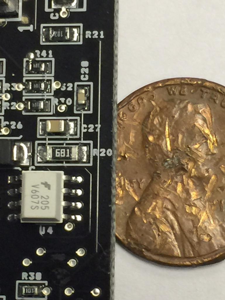
I will start the engine removal this weekend.
Posted by: Mblizzard Jun 14 2017, 09:34 AM
That circuit is weak for filtering the noisy flyback high voltage from the ignition coil. You will have dropped signals at higher RPMs. I strongly recommend aborting on the OPTOIN - and OPTOIN + nonsense circuit and going with the safer trigger wheel route and don't look back.
If you insist on making this work, you should replaced that resistor with a higher wattage and either buy or make a circuit to better shape and condition that noisy incoming signal. Or, have a spare microsquirt handy because if this fails again, it will leave you stranded somewhere, but what do I know
Got a reply back from DIY and they suggested a 1/2 watt resistor mounted off the board?
They offered to complete the repair no problem. But as Tim said this still has limits. But I think I will send it in for the repair as a back up operation mode.
Posted by: Mblizzard Jun 14 2017, 09:51 AM
Received the trigger wheel and goodies from McMark!
OK so I have not completely read the instructions provided but I thought I would ask if someone had the correct settings for this in regards to teeth and correct angle? 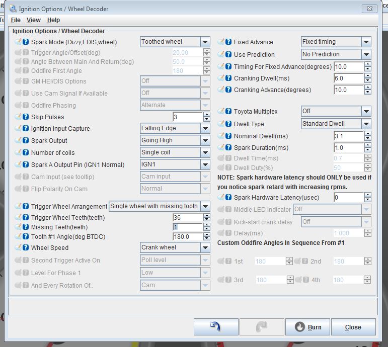
Should start the install this weekend.
Posted by: McMark Jun 14 2017, 11:18 AM
I usually start with an Offset Angle of 290°. From your screen grab it looks like the MS2E software call that Tooth #1 Angle.
If nothing happens when you first start with the crank trigger, try swapping the Ignition Input Capture from Falling Edge to Rising Edge. With the MicroSquirt firmware and running ignition, the engine won't start with that setting backwards. So it's pretty easy to tell. You can also figure it out definitively by loading the Tooth Analyzer firmware and looking at the waveform it spits out.
Posted by: Vacca Rabite Jun 15 2017, 07:17 AM
Ahh, the 2pin Bosch connector. I'll throw one in with your VR sensor, Mike. (Shipping today...
)Zach, I'll send one your way too, with a couple AMP35 pins.
I had not seen this post and got your package in the mail on my birthday earlier this week. THANKS! I was totally surprised.
Zach
Posted by: McMark Jun 15 2017, 07:24 AM
Ahh, the 2pin Bosch connector. I'll throw one in with your VR sensor, Mike. (Shipping today...
)Zach, I'll send one your way too, with a couple AMP35 pins.
I had not seen this post and got your package in the mail on my birthday earlier this week. THANKS! I was totally surprised.
Zach


Posted by: Mblizzard Jun 15 2017, 07:52 AM
I usually start with an Offset Angle of 290°. From your screen grab it looks like the MS2E software call that Tooth #1 Angle.
If nothing happens when you first start with the crank trigger, try swapping the Ignition Input Capture from Falling Edge to Rising Edge. With the MicroSquirt firmware and running ignition, the engine won't start with that setting backwards. So it's pretty easy to tell. You can also figure it out definitively by loading the Tooth Analyzer firmware and looking at the waveform it spits out.
I guess the question I have is relative to TDC what angle is the missing tooth?
The information in the manual is not very clear.
From the manual:
Trigger Angle/Offset (deg)
In 'Toothed Wheel' this should always be set to zero – use tooth #1 angle instead.
Maybe it is that I read things too literal but if it should always be set to 0 and you are to use the #1 angle does that mean tooth #1 has to be at TDC? Or is the missing tooth TDC?
Tooth #1 Angle (deg BTDC)
Generally (with a missing tooth crank wheel) tooth #1 is the first tooth to pass the sensor after the missing tooth gap.
This would seem to follow McMark (290) and suggests that missing tooth should be TDC.
Posted by: McMark Jun 15 2017, 08:24 AM
The missing tooth can be anywhere.
The sensor location can be anywhere.
The setting is there to tell the ECU how many degrees between TDC and when it senses the missing tooth. In the case of my trigger wheel, the missing tooth passes the sensor 290(ish) degrees away from TDC.
Attached image(s)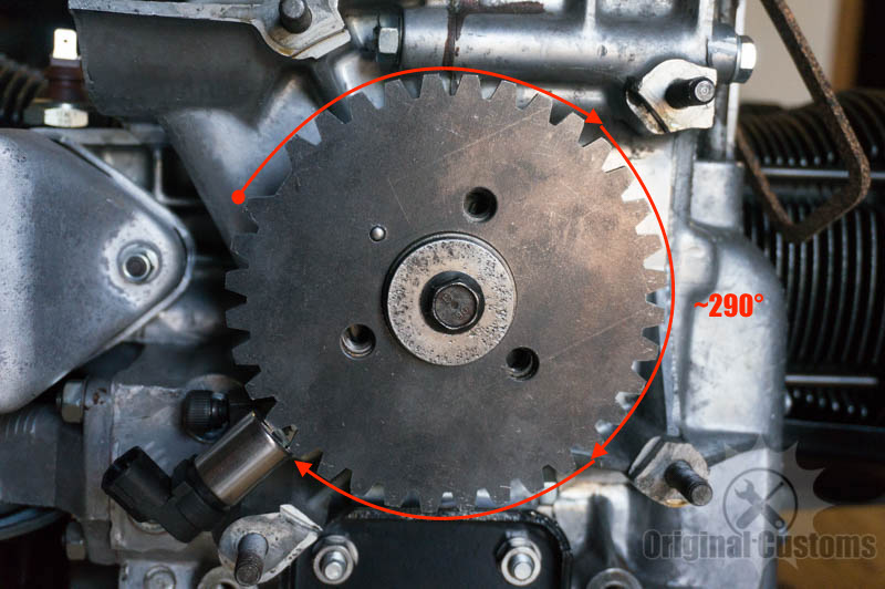
Posted by: Mblizzard Jun 15 2017, 08:45 AM
The missing tooth can be anywhere.
The sensor location can be anywhere.
The setting is there to tell the ECU how many degrees between TDC and when it senses the missing tooth. In the case of my trigger wheel, the missing tooth passes the sensor 290(ish) degrees away from TDC.
Well that picture certainly clears up a lot of useless gibberish in the manuals!

By the time we are done there will be a lot of useful information in this thread.
Posted by: LowBridge Jun 15 2017, 12:36 PM
The missing tooth can be anywhere.
The sensor location can be anywhere.
The setting is there to tell the ECU how many degrees between TDC and when it senses the missing tooth. In the case of my trigger wheel, the missing tooth passes the sensor 290(ish) degrees away from TDC.
Well that picture certainly clears up a lot of useless gibberish in the manuals!
By the time we are done there will be a lot of useful information in this thread.
I have been following this waiting to see how it ends up because I have been thinking about this very conversion to my 2.0 w/carbs
Posted by: Mblizzard Jun 15 2017, 05:19 PM
As the reality of modern business becomes more appearemt to all of us in the form of lower expectations, it is great to know we have people like McMark and Orginal Customs who make us understand that there are a few that still share our values and passion.
Just got this in and it is TOP SHELF and is on par with every item I have gotten from Orginal Customs from my complete engine to the smallest part. Well done sir!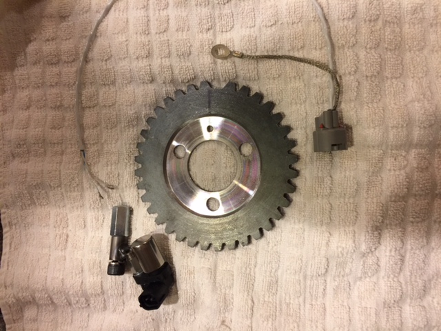
Posted by: Mblizzard Jul 9 2017, 01:06 PM
Progress made today finally. Engine dropped. Taken apart and trigger wheel,added. AC compressor out. Reassembled and ready to slip back in after some wiring and setting the valves. 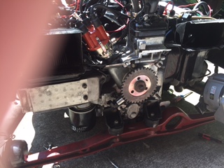
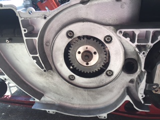
Posted by: Montreal914 Jul 9 2017, 01:32 PM
Nice 
Posted by: Mblizzard Jul 14 2017, 10:35 AM
Doug (dlee6204) makes a neat bracket that mounts the sanden compressor on top. I bought his pulley adapter for this conversion but have decided to go a different route, it's all yours if you want it.
I would be interested in that for sure.
Posted by: Mblizzard Jul 16 2017, 03:54 PM
Well! Engine back in. Most of the wiring done. All of the things I was going to do with the next engine drop (new starter, change CHT lead, change clutch pull from crap plastic to metal, add SS oil cooler lines, space out oil cooler, and others) done.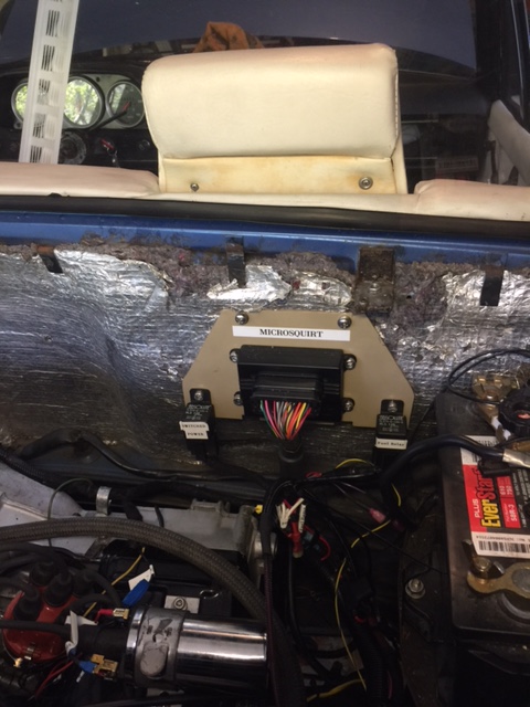
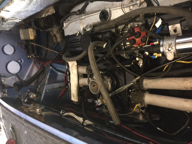
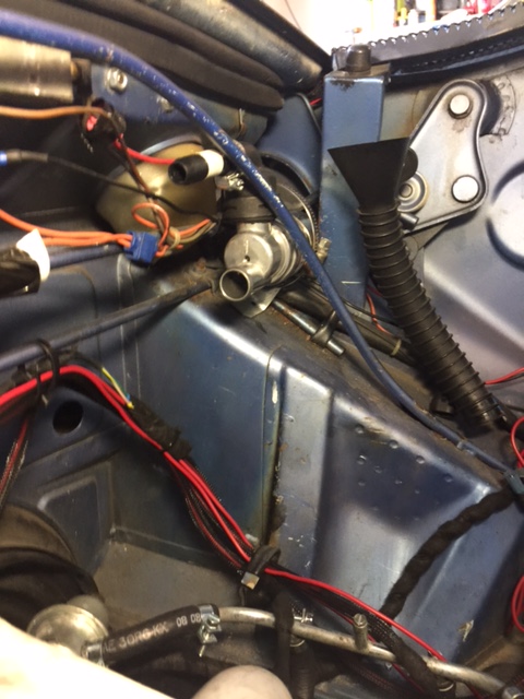
Now just have to button up the lose ends and then see if it works!
Attached image(s)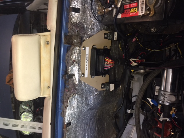
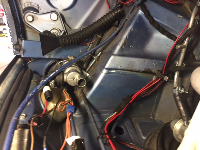
Posted by: McMark Aug 14 2017, 02:34 PM
Reviving this thread since I'm just going through configuring one of my MicroSquirt injection setups, but running the MS2Extra firmware.
It appears that the MicroSquirt firmware and the MS2Extra firmware use this 'Trigger Offset' and 'Tooth #1 Angle' differently. I had this car running on the MicroSquirt firmware with a Trigger Offset of 298.2°. Now that I've installed the MS2Extra firmware, it didn't want to start with that as the Tooth #1 Angle setting. I had to go the other direction and put in a setting of 75 to start (which started to run, but barely). Doing the math (360-298.1) gives me 61.8. I'll be tuning the Tooth #1 Angle setting tomorrow with a timing light and will update this post with my final Angle setting.
But this is just another example of how the settings between different firmwares can be drastic, and so if you're researching MegaSquirt settings it's vitally important that you know which firmware corresponds to the information your looking at. A quick web search can send you far down a wrong path if you don't pay attention. 
Posted by: Mblizzard Aug 22 2017, 10:55 AM
OK so lots of work and no more success!
Got McMarks tooth wheel installed and it seems to be putting out a fine signal. 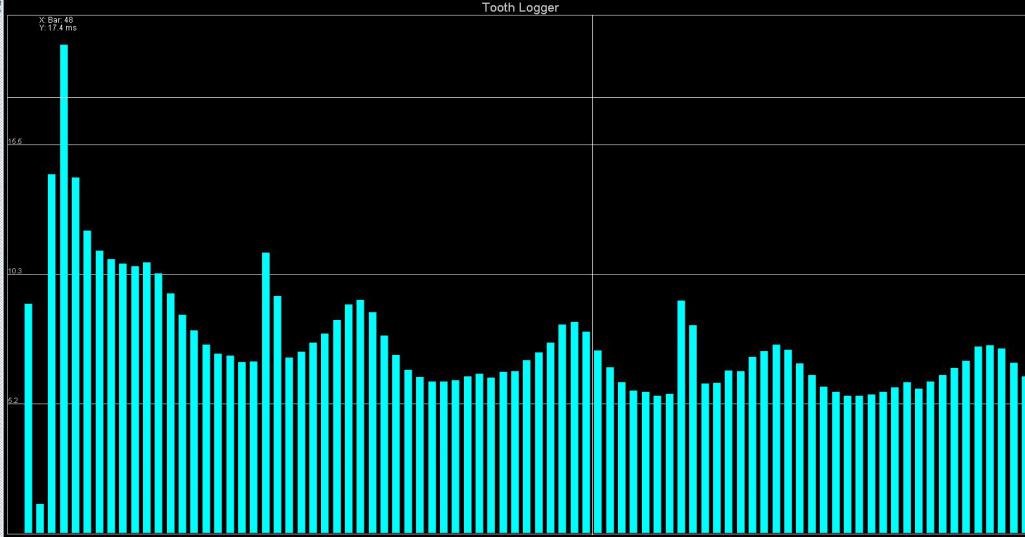
But the injectors are not firing.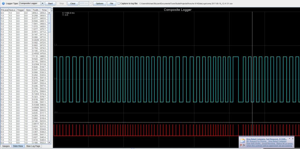
Not sure if I am missing something on the settings that tells the injectors when to fire but the data shows all "zeros" so I don't think it is getting a triggering event.
I have injection set to untimed injection which = batch fire but it never fires. Is there something else I have to change in the settings to trigger the injectors? 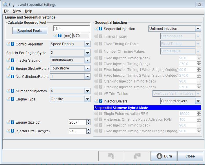
Ordered new Micro Squirt to see if the resistor problem is the cause.
Posted by: crash914 Aug 22 2017, 11:50 AM
I don't believe that the type 4 is an "odd" fire engine. that is for 5 cylinder and Harleys....etc. I think?
Posted by: Mblizzard Aug 22 2017, 12:25 PM
I don't believe that the type 4 is an "odd" fire engine. that is for 5 cylinder and Harleys....etc. I think?
I tried it both ways but still no injector trigger. I have not switched over to using the Micro squirt to control timing yet so I have no idea if this matters to the firing of the injectors.
Posted by: McMark Aug 22 2017, 12:38 PM
Odd fire relates to engines who's cyilnders don't fire 180-degrees off. Which means most every engine out there is NOT Odd fire.
Does the RPM gauge rise when cranking? If not switch the Ignition Options -> Ignition Input Capture (from Rising Edge to Falling Edge, or visa versa).
Posted by: Mblizzard Aug 22 2017, 12:54 PM
Odd fire relates to engines who's cyilnders don't fire 180-degrees off. Which means most every engine out there is NOT Odd fire.
Does the RPM gauge rise when cranking? If not switch the Ignition Options -> Ignition Input Capture (from Rising Edge to Falling Edge, or visa versa).
Humm... Just a thought. I was just reading the RMP gauge normally off the coil so I did not have the Tacho output enabled.
Looking at the wire diagram it seems like the VR circuit would like to have that signal. That may explain all of the zeros for the trigger.
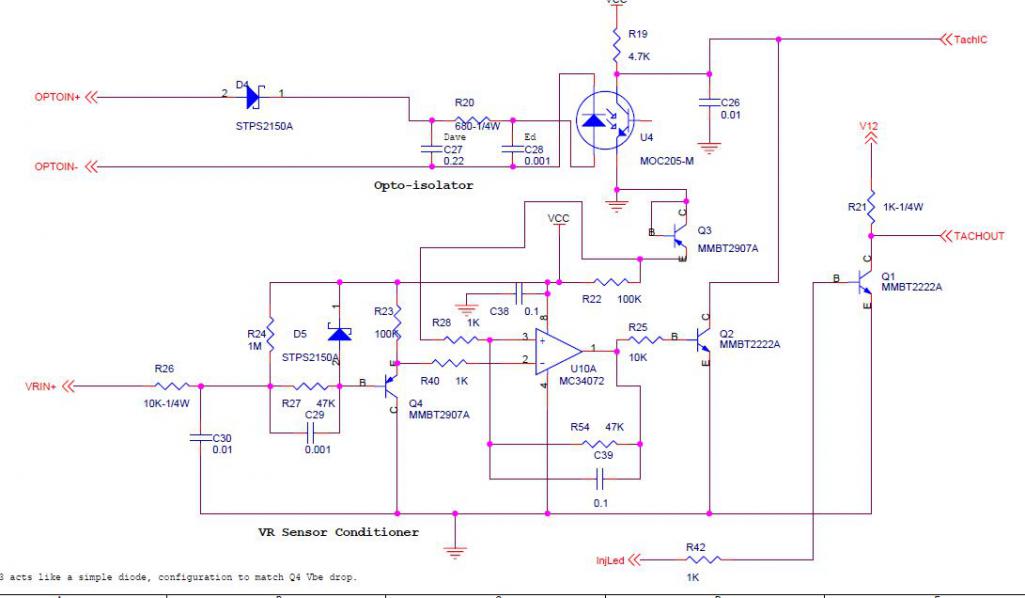
Posted by: Mblizzard Aug 22 2017, 02:34 PM
Odd fire relates to engines who's cyilnders don't fire 180-degrees off. Which means most every engine out there is NOT Odd fire.
Does the RPM gauge rise when cranking? If not switch the Ignition Options -> Ignition Input Capture (from Rising Edge to Falling Edge, or visa versa).
Just did a bit more reading and looks like your suggestion may be right. Manual says this is a pattern of a VR wired incorrectly.
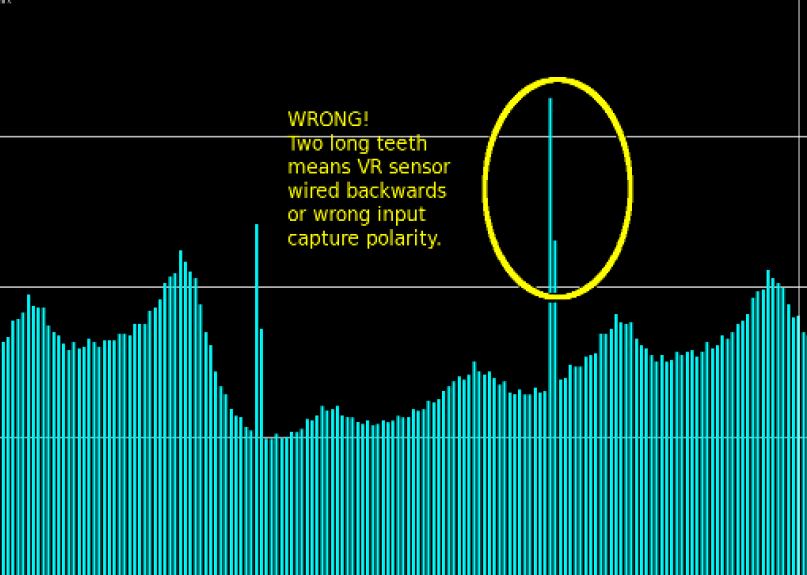
Posted by: McMark Aug 22 2017, 02:39 PM
Tachout shouldn't have anything to do with anything but your gauge.
Posted by: Mblizzard Aug 23 2017, 04:09 PM
Beyond frustrated! New controller allowed the engine to start but can't get it to even idle or remotely run.
Anyone have a tune that will allow the damn thing to run?
Need to drink gin and tonic!
Posted by: 76-914 Aug 23 2017, 04:51 PM
I'm surprised your not "knee walking" drunk already. 
Posted by: Mblizzard Aug 24 2017, 04:07 PM
Progress was made. I have a good solid idle but dies on trying to accelerate!
Time to drink more. Any suggestions on what setting i may have wrong?
Posted by: 914Tom Sep 12 2017, 04:16 AM
Posted by: poorsche914 Sep 12 2017, 08:49 AM
The journey continues in http://www.914world.com/bbs2/index.php?showtopic=315413
Posted by: Vacca Rabite Sep 12 2017, 08:59 AM
Now that it is running GET IT DYNO TUNED.
Seriously, you will be chasing your tail for a long time. Let a pro handle it now, and you will be driving your car.
Zach
Posted by: Mblizzard Sep 12 2017, 09:06 AM
Now that it is running GET IT DYNO TUNED.
Seriously, you will be chasing your tail for a long time. Let a pro handle it now, and you will be driving your car.
Zach
I will do that after I add the ignition component but I don't know of anyone local that does this.
Posted by: Mblizzard Sep 12 2017, 09:06 AM
The journey continues in http://www.914world.com/bbs2/index.php?showtopic=315413
That's my bitter thread! did not want to discourage people.
Posted by: McMark Sep 19 2017, 11:56 AM
Just went through configuring a MicroSquirt brain running MS2E firmware and the trigger offset (Trigger #1 Angle) settings are calculated differently between the two firmwares.
MicroSquirt 3.83 firmware would end up being around 290° as mentioned above.
but...
Mike is running the MS2E firmware and the angle for that is around 60°.
Attached image(s)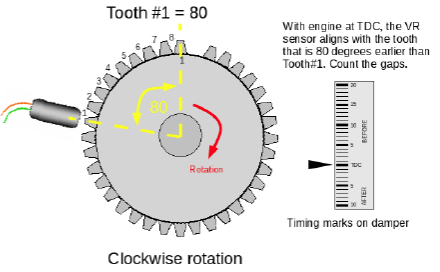
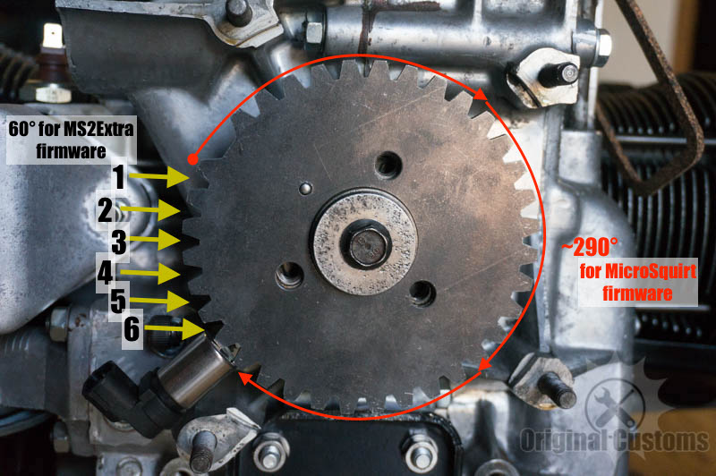
Posted by: Mblizzard Nov 8 2017, 01:21 PM
OK so now I am really confused.
I noted Marks comment about the firmware. I noticed that I was not running the latest MicroSquirt Firmware. So I decided to update.
I got a whole bunch of crap that did not seem to work anymore. 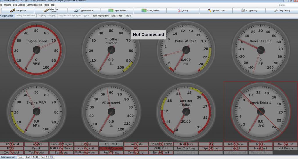
When I made a new project under the new firmware there were a lot less options available for setting things up. Like no programmable on/offs. 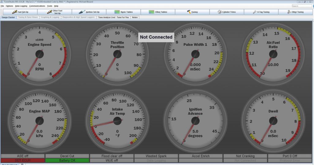
Not sure this is what I want. Any idea if I screwed something up in the firmware update or is this what it is suppose to be?
Posted by: crash914 Nov 8 2017, 01:38 PM
difference is Microsquirt firmware and MS@Extra firmware.
Both can be run on Microsquirt hardware.
Please list what you are using? unless you did before...
Posted by: Mblizzard Nov 8 2017, 01:44 PM
difference is Microsquirt firmware and MS@Extra firmware.
Both can be run on Microsquirt hardware.
Please list what you are using? unless you did before...
Was running the MS2E firmware V3.0.28 on the Microsquirt controller.
Posted by: crash914 Nov 8 2017, 01:50 PM
Might be worth it to upgrade to the 3.4.2 version.
here:http://www.msextra.com/downloads
Posted by: Mblizzard Nov 8 2017, 02:05 PM
So what I am seeing is that going to the Microsquirt code is a downgrade compared to MS-II?
Posted by: crash914 Nov 8 2017, 02:12 PM
I am not the best one to answer that, Mark would know better, however for me, I need to use the "EXTRA" code for the sequential injection mode for fuel and spark. The standard code doesn't have that option.
Posted by: Mblizzard Nov 13 2017, 02:44 PM
OK so it is clear that the MicroSquirt Code is not what I want to use! Thank goodness for back up files. All switched back to MegaSquirt.
I have been chasing some vacuum leaks for some time. I finally found a major one yesterday. Could not get a photo but on the 2.0 plenum the throttle body is mounted on there are two support tubes that run from the top to the bottom. The weld on both of these tubes is sucking air! Did a quick fix on the top side but I would think it might be leaking on the bottom as well.
Likely explains my idle issues. I think as the engine heated up the break expanded. I checked for leaks countless times but I never thought these would be the source.
Drove for a while after and let the autotune work. Will have to play with the tune a bit more.
Posted by: McMark Nov 13 2017, 04:53 PM
I wish there was a 'recommended firmware' page for the MicroSquirt. The MicroSquirt firmware seems to be stagnant at 3.83. I have the impression that MS2E firmware has become the standard. That's what DIYAutotune ships on new MicroSquirt ECUs, and it's what I'm moving everything over to. There's a lot more features.
Cracked and/or rusted plenums seem to be a more and more common issue. I sent one 2.0 plenum out for blasting and powdercoating. Came back with swiss-cheese holes on the bottom. You should pull the entire thing to fix it correctly.
Posted by: Dave_Darling Nov 13 2017, 09:22 PM
A relatively common issue. I've hit it more than once. Anyone with 2.0 manifolds should check those.
--DD
Posted by: Mblizzard Nov 14 2017, 09:51 AM
Drove to work this morning running auto tune on my laptop. Revised a number of values on the VE table. But more consistently seeing target AFR matching real-time AFR.
Getting much lower MAP at idle. But I still think I am missing some power. May be that the bottom part of the engine is tired. Wondering if I have some excessive cam wear and I am just not getting full performance. Will work with McMark on that.
I just don't get the quick throttle response from the engine when going along and have to hit it hard. Don't expect it to spin the tires in 5th gear or anything would like to see a bit more punch.
I am using 100% TPS accel enrichment. Will work a bit more on getting the VE table refined and then dial in the TPS accel a bit more. Not seeing it go lean on accel so I think it is getting enough fuel. 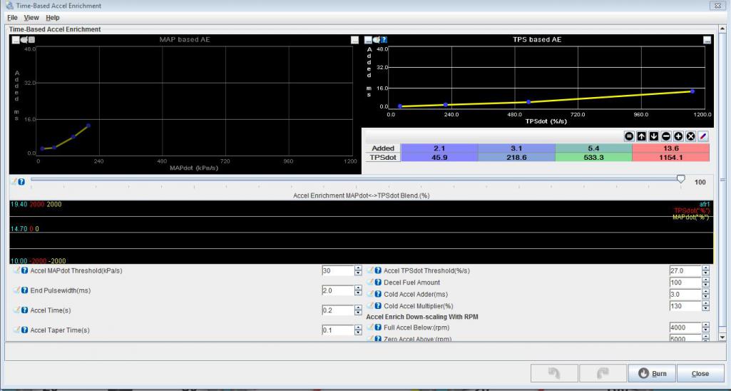
Posted by: McMark Nov 14 2017, 10:46 AM
Where's the datalog?
Posted by: Mblizzard Nov 14 2017, 11:04 AM
Where's the datalog?
Forgot to push the button! Will log on the way home tonight!
Posted by: Mblizzard Nov 29 2017, 05:09 PM
Well thanks to some good weather I have drive the car to work for several days using the auto tune.
After correcting the vacuum leaks it looks like i have a pretty good VE table and using James timing table I am getting some really respectable performance and my CHT temps have been good. Still a bit higher than I would like but even on long hill pulls they don’t go above 370.
The car is a blast to drive now and has good enough performace to keep up with my wife’s Boxster for a bit. Of course it is a base engine with auto trans so that is not as outlandish at it would seem.
Overall a long road but I would still recommend it to others. Can’t say it is light years ahead of the stock system but it does provide more tuning options that will allow you to get the most out of your car while having a very reliable system.
Posted by: McMark Nov 29 2017, 05:25 PM
Posted by: Mueller Nov 29 2017, 05:37 PM
Well thanks to some good weather I have drive the car to work for several days using the auto tune.
After correcting the vacuum leaks it looks like i have a pretty good VE table and using James timing table I am getting some really respectable performance and my CHT temps have been good. Still a bit higher than I would like but even on long hill pulls they don’t go above 370.
The car is a blast to drive now and has good enough performace to keep up with my wife’s Boxster for a bit. Of course it is a base engine with auto trans so that is not as outlandish at it would seem.
Overall a long road but I would still recommend it to others. Can’t say it is light years ahead of the stock system but it does provide more tuning options that will allow you to get the most out of your car while having a very reliable system.
Congrats!
I know it was borderline torture for you going down this path, but now you can look back and think of all the things you learned going thru this experience. In the near future you will be able to offer advice and help to someone struggling with their install.
Posted by: BeatNavy Nov 29 2017, 06:14 PM
Congrats!
I know it was borderline torture for you going down this path, but now you can look back and think of all the things you learned going thru this experience. In the near future you will be able to offer advice and help to someone struggling with their install.
Nice job, Mike. Thanks for posting your experiences online, including sharing your challenges and setbacks. I'm going this route, but I'm having someone else do most of the hard work. I hope you've got some great satisfaction after all that hard work. You deserve it
Posted by: Mblizzard Nov 29 2017, 07:15 PM
Well thanks to some good weather I have drive the car to work for several days using the auto tune.
After correcting the vacuum leaks it looks like i have a pretty good VE table and using James timing table I am getting some really respectable performance and my CHT temps have been good. Still a bit higher than I would like but even on long hill pulls they don’t go above 370.
The car is a blast to drive now and has good enough performace to keep up with my wife’s Boxster for a bit. Of course it is a base engine with auto trans so that is not as outlandish at it would seem.
Overall a long road but I would still recommend it to others. Can’t say it is light years ahead of the stock system but it does provide more tuning options that will allow you to get the most out of your car while having a very reliable system.
Congrats!
I know it was borderline torture for you going down this path, but now you can look back and think of all the things you learned going thru this experience. In the near future you will be able to offer advice and help to someone struggling with their install.
Got so much support from the world and I hope I can help out anyone else who goes down this path. There are so many others that have more experience but I will do,what I can.
Posted by: boxsterfan Nov 29 2017, 08:05 PM
Awesome to hear this worked out!!! I plan on putting this system in my 914 2270 also (someday)!!
Posted by: Montreal914 Nov 29 2017, 11:05 PM
Congrats on the great achievement. 
Like many others, it is my goal to convert my 2056 to Mega or Micro in a near future. Your shared experience has been very inspirational and will certainly help a lot.
Posted by: Mueller Dec 1 2017, 12:18 AM
Got so much support from the world and I hope I can help out anyone else who goes down this path. There are so many others that have more experience but I will do,what I can.
Did you get the 30 inch harness or the 8 foot harness?
After spending an hour in the garage tonight looking for my old Megasquirt boxes I only found one which seems fairly incomplete and some components like the drivers are mounted on the heat sink yet the leads are cut off completely. Wife said just buy a new one after seeing my displeasure and it seems Microsquirt is the way to go.
Posted by: JamesM Dec 3 2017, 01:14 AM
Got so much support from the world and I hope I can help out anyone else who goes down this path. There are so many others that have more experience but I will do,what I can.
Did you get the 30 inch harness or the 8 foot harness?
After spending an hour in the garage tonight looking for my old Megasquirt boxes I only found one which seems fairly incomplete and some components like the drivers are mounted on the heat sink yet the leads are cut off completely. Wife said just buy a new one after seeing my displeasure and it seems Microsquirt is the way to go.
Go with the 8 foot harness.
Microsquirt is preferable to a full blown Megasquirt box in a 914 for a few reasons but mainly because its components are spec'd to be installed in an engine bay whereas the standard megasquirt box should be installed in the cabin or trunk.
If you want I can send you an "easy button" preferred parts shopping list that I have supplied to people. I was thinking about doing another build this winter so maybe ill get around to finally putting together a "how to" pictorial thread start to finish. That is if this other secret project I just picked up doesn't get in the way to much.
Posted by: JamesM Dec 3 2017, 02:08 AM
Well thanks to some good weather I have drive the car to work for several days using the auto tune.
After correcting the vacuum leaks it looks like i have a pretty good VE table and using James timing table I am getting some really respectable performance and my CHT temps have been good. Still a bit higher than I would like but even on long hill pulls they don’t go above 370.
The car is a blast to drive now and has good enough performace to keep up with my wife’s Boxster for a bit. Of course it is a base engine with auto trans so that is not as outlandish at it would seem.
Overall a long road but I would still recommend it to others. Can’t say it is light years ahead of the stock system but it does provide more tuning options that will allow you to get the most out of your car while having a very reliable system.
Glad to hear, sounds like it going well. If 370 is the hottest the heads get under worst case operating conditions with a stock cam I would say you have it pretty dialed in. As far as performance goes, Megasquirt is great for extracting every possible last bit of performance and driveability from an engine but in the end the limiting factor is still how well the engine can pump air. The cool thing now though is that your fueling system can be easily tuned to virtually anything you decide you want to change on the engine itself. Even cooler (to a nerd like me anyways) is that you can then see exactly where the engine performs differently just by comparing the changes in the fuel map.
So bottom line, now you are just looking for an excuse to build a crazier motor!
Posted by: Mueller Dec 3 2017, 03:32 PM
Go with the 8 foot harness.
Microsquirt is preferable to a full blown Megasquirt box in a 914 for a few reasons but mainly because its components are spec'd to be installed in an engine bay whereas the standard megasquirt box should be installed in the cabin or trunk.
If you want I can send you an "easy button" preferred parts shopping list that I have supplied to people. I was thinking about doing another build this winter so maybe ill get around to finally putting together a "how to" pictorial thread start to finish. That is if this other secret project I just picked up doesn't get in the way to much.
Makes sense, easier to shorten than stretch a wire
What spark plug wires to use for the VW coil that plays nice with the Type IV?
Ordering parts this week.
Posted by: Mueller Dec 5 2017, 10:23 AM
Go with the 8 foot harness.
Microsquirt is preferable to a full blown Megasquirt box in a 914 for a few reasons but mainly because its components are spec'd to be installed in an engine bay whereas the standard megasquirt box should be installed in the cabin or trunk.
If you want I can send you an "easy button" preferred parts shopping list that I have supplied to people. I was thinking about doing another build this winter so maybe ill get around to finally putting together a "how to" pictorial thread start to finish. That is if this other secret project I just picked up doesn't get in the way to much.
Bump for this list
Items I have so far:
GM air temp sensor
TPS (proper potentiometer TPS) however I thought I read about a better newer style TPS?
Innovate WB02 setup
2 Bar MAP sensor (not bought yet, still in my Amazon cart) currently N/A however might follow Marks low boost turbo design down the road.
Used Ford Yellow top 19lb injectors
Posted by: jd74914 Dec 5 2017, 12:10 PM
TPS (proper potentiometer TPS) however I thought I read about a better newer style TPS?
Not sure how they fit up to the stock TB, but the latest rage in TPS sensors are the non-contact Hall effect type (Littlefuse 55250-00-00-0 for example). Compact, relatively low cost, and crazy reliable.
2 Bar MAP sensor (not bought yet, still in my Amazon cart) currently N/A however might follow Marks low boost turbo design down the road.
The're a little on the pricey side (~$40) but the Bosch TMap sensors are pretty nice. They combine the MAP/IAT sensors into one package and insert right into the manifold. You'd just need to machine a small plate with through hole and tapped hole for fastening. Then only one cable to the ECU and no vacuum lines.
https://www.bmotorsports.com/shop/index.php/cPath/129_143
Posted by: Mblizzard Dec 5 2017, 12:13 PM
Go with the 8 foot harness.
Microsquirt is preferable to a full blown Megasquirt box in a 914 for a few reasons but mainly because its components are spec'd to be installed in an engine bay whereas the standard megasquirt box should be installed in the cabin or trunk.
If you want I can send you an "easy button" preferred parts shopping list that I have supplied to people. I was thinking about doing another build this winter so maybe ill get around to finally putting together a "how to" pictorial thread start to finish. That is if this other secret project I just picked up doesn't get in the way to much.
Bump for this list
Items I have so far:
GM air temp sensor
TPS (proper potentiometer TPS) however I thought I read about a better newer style TPS?
Innovate WB02 setup
2 Bar MAP sensor (not bought yet, still in my Amazon cart) currently N/A however might follow Marks low boost turbo design down the road.
Used Ford Yellow top 19lb injectors
If you have not done it down load the current version of http://www.tunerstudio.com/index.php/tuner-studio from EFI. Good to enter some of your values ahead of the build. Can send some tunes and log files so you can see how things work.
I have a 3-bar sensor if you want it I can send it with the coil wire.
Would recommend getting the TPS set up from Original Customs it is a easy install and the bracket is done for you. The trigger wheel and VR sensor from OC is a good call as well. Takes a lot of guess work out of the effort. Installs easily but while some say they could do it with engine in, my "man hands" just couldn't even begin to get into the tight space.
You can find the IAT sensor for as little as $10 if you shop. Part Numbers GM part # 25036751 or Borg Warner WT382.
If you don't have one, I would invest in a good professional quality crimping tool and some quality connectors. The debate of solder vs crimp will rage forever but a good crimp tool will save you time and make good connections quickly.
Posted by: Mblizzard Dec 5 2017, 12:50 PM
TPS (proper potentiometer TPS) however I thought I read about a better newer style TPS?
Not sure how they fit up to the stock TB, but the latest rage in TPS sensors are the non-contact Hall effect type (Littlefuse 55250-00-00-0 for example). Compact, relatively low cost, and crazy reliable.
2 Bar MAP sensor (not bought yet, still in my Amazon cart) currently N/A however might follow Marks low boost turbo design down the road.
The're a little on the pricey side (~$40) but the Bosch TMap sensors are pretty nice. They combine the MAP/IAT sensors into one package and insert right into the manifold. You'd just need to machine a small plate with through hole and tapped hole for fastening. Then only one cable to the ECU and no vacuum lines.
https://www.bmotorsports.com/shop/index.php/cPath/129_143
WOW that is a good deal on that sensor MAP and IAT for $40. Would be a very simplified install. That may be the best approach I have seen. Assuming that the IAT and the MAP in the same location works. Seems like it should.
Posted by: jd74914 Dec 5 2017, 01:12 PM
WOW that is a good deal on that sensor MAP and IAT for $40. Would be a very simplified install. That may be the best approach I have seen. Assuming that the IAT and the MAP in the same location works. Seems like it should.
I've used them on a few builds now and been very happy. IMHO it's the cleanest setup for a car with nice central plenum. When my 2.0 goes MS3 it's going to get a TMAP.
Posted by: JamesM Dec 10 2017, 03:26 AM
Go with the 8 foot harness.
Microsquirt is preferable to a full blown Megasquirt box in a 914 for a few reasons but mainly because its components are spec'd to be installed in an engine bay whereas the standard megasquirt box should be installed in the cabin or trunk.
If you want I can send you an "easy button" preferred parts shopping list that I have supplied to people. I was thinking about doing another build this winter so maybe ill get around to finally putting together a "how to" pictorial thread start to finish. That is if this other secret project I just picked up doesn't get in the way to much.
Bump for this list
Items I have so far:
GM air temp sensor
TPS (proper potentiometer TPS) however I thought I read about a better newer style TPS?
Innovate WB02 setup
2 Bar MAP sensor (not bought yet, still in my Amazon cart) currently N/A however might follow Marks low boost turbo design down the road.
Used Ford Yellow top 19lb injectors
Sorry I haven't been on in a while, to many projects. Received multiple DMs about this but haven't had time to respond to them, given the interest ill work on putting together an end to end how to thread as soon as I can get some time. Until then here is a short list of the major components that can be used regardless of your induction method. In order to give a complete parts list I would need to know if this is for a d-jet conversion or an independent throttle body setup.
May ways this can be done but this list is focused on using a Microsquirt ECU and what I have found to be the simplest way to go while being as affordable as possible.
So here we go....
First off the ECU itself
Microsquirt with 8ft base harness. The main connector is already in place and the wires color coded so all that is needed is end connectors to be sourced and components wires up - Currently ~$390
https://www.diyautotune.com/product/microsquirt-engine-management-system-w-8-39-wiring-harness/
For Ignition Input - this is my preferred crank trigger package . Very secure mounting and uses a Hall sensor that produces a very clean square wave - Currently $149
http://thedubshop.goodsie.com/type-4-crank-trigger-package
Ignition output - VW wasted spark coil (VW part 032905106B)
Genuine VW can be pretty pricey but aftermarket can be had for $20 new. This is a logic level coil so no ignition drivers are needed, the Microsquirt gets wired directly to it with 3 wires.
https://www.amazon.com/ECCPP-032905106-610-58552-Ignition-Volkswagen/dp/B00UA2YI4W
Due to the nature of wasted spark systems they can be hard on spark plugs so i have been looking into a newer 4 channel logic level VW coil but as i haven't personally ran one yet I am not going to list it. I have used the coil above on multiple installs so that is what im listing for now. Its super easy and it works great.
MAP Sensor - Use the 1-bar Standard GM map sensor. The reason I recommend the 1 bar rather than the 2 or 3 bar is that it provides better resolution in a naturally aspirated application. Last ones I purchased at a FLAPS (every FLAPS should have them). You can find them pretty much anywhere from $15-$60
Lots of different part numbers,i don't have the exact ones I used handy but they are used on pretty much any non boosted injected GM car from the 80s and 90s. If you want to do real time barometric correction you will need 2 of these.
Identification guide
https://sites.google.com/site/sloppywiki/everything-ls/gm-map-sensor-identification
http://www.rockauto.com/en/catalog/cadillac,1985,eldorado,4.1l+250cid+v8,1026100,fuel+&+air,manifold+pressure+(map)+sensor,11207
Those are the main components. Any other components you need (Wiring connectors, throttle position sensor, air temp sensor, head temp sensor, injectors) depend on what you plan on attaching the megasquirt to (existing d-jet, ITBs or whatever). The above are a starting point for all though.
When i get some time ill put together a how to thread that dives more into the specifics, but in the mean time here a are a couple of my favorite sources for neat stuff you might use:
https://reproparts.wazala.com/
has lots of cool stuff but of specific importance are:
https://reproparts.wazala.com/products/porsche-914-relay-plug-connector/
-Useful for wiring your harness to the stock relay board location for power and fuel pump relay
https://reproparts.wazala.com/products/d-jetronic-2-pole-plug-housing/
https://reproparts.wazala.com/products/d-jetronic-2-pole-boot-grip-style/
-Usefull if you want to use d-jet injectors
https://www.fiveomotorsport.com/a280-a380-high-impedance-hose-type-fuel-injector
-Brand new High-Z injectors(so you dont need a resistor pack) that fit the d-jet and l-jet intake runners and have locking connectors.
http://www.thedubshop.net/products
Lots and lots of handy stuff depending on your application
Posted by: Mblizzard Dec 12 2017, 01:33 PM
So still enjoy driving. Running Auto Tune every so often and making minor changes but basically have a solid running system!
Up until this point I have not messed much with the idle control I have just been using a manual valve to let in more air on cold starts. I have a Bosch type 2-wire IAC valve. I have played around with it a bit and really cant see that it ever closes enough to bring the idle down into the target range.
I have verified that the valve mode is normally off at 0% duty. I have played around with the valve frequency but have not really seen a difference in the operation. Tuner Studios suggests that Bosch valves operate at 50-100 Hz.
Anyone have any experience setting up the Bosch IAC?
Posted by: McMark Dec 14 2017, 08:45 AM
Those IAC always seem SOOOO huge to me. I played with one for awhile and couldn't really get it dialed in. I didn't spend a bunch of time on it, and I'm sure it's possible. But since aesthetics are important to me as well, I didn't bother investing much time since I knew I wasn't going to find a mounting setup that made sense, the whole thing occupies too much space, and the inlet/outlet ports are so huge that it'd need ugly adapters on both sides to bring them down to 13mm to match the ports on our engine.
I guess I need to actually get my new Hyundai IAC setup bench tested and then send it out to you for functional testing.
Powered by Invision Power Board (http://www.invisionboard.com)
© Invision Power Services (http://www.invisionpower.com)