Printable Version of Topic
Click here to view this topic in its original format
914World.com _ 914World Garage _ D-Jet vacuum hose question
Posted by: Olympic 1.7 Feb 10 2017, 07:45 AM
Just finished up installing all the FI wiring harness and the vacuum hoses and now the engine compartment looks like a bowl of Spaghetti.
This engine started out as a 73 1.7 with the stock FI and I converted everything to a 2.0 system. I did use some of the original 1.7 parts as they were the same for both engines. But all the 2.0 FI parts ( throttle body, plenum, air filter housing ,etc.) where cobbled together from fleabay purchases and I am not sure what years those parts were from. Also used the original 73 1.7 FI wiring harness and ECU and had to make a couple extensions to get everything to hook up. Not much problem there, (except for trying to connect those ground wires under the plenum. )
Now to the question, I was using Bowlsby's vacuum diagram that is for a late 74 2.0 system and while hooking up the vacuum lines to the dizzy it seem that one line is no longer used.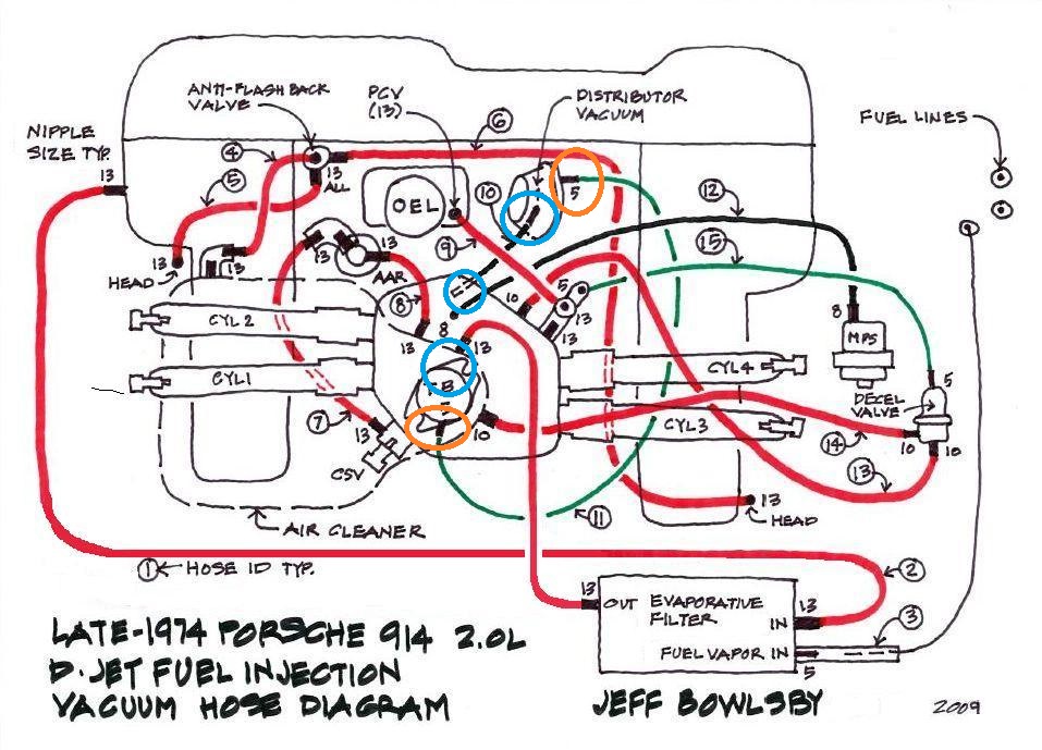
in the diagram above I have the green vacuum hose connected from the throttle body to the dizzy as shown by the Orange circles. I also have another vacuum port on my dizzy that I have connected to the second vacuum port on my throttle body shown by Blue circles.
Should I have both of these hooked up? or do I disconnect the Black vacuum line as shown in Bowlsby's diagram and just plug the second port on the throttle body.
This is what I have hooked up now.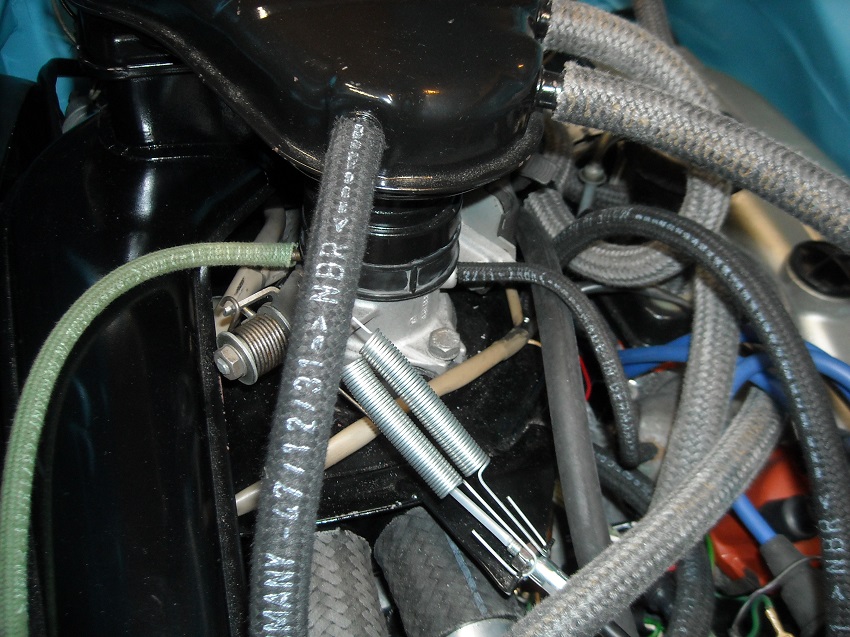
Is there a reason that the later versions did not have this second port hooked up?
What benefits are there to using the second line to the dizzy vacuum canister?
in picture below the green line from the throttle body is routed differently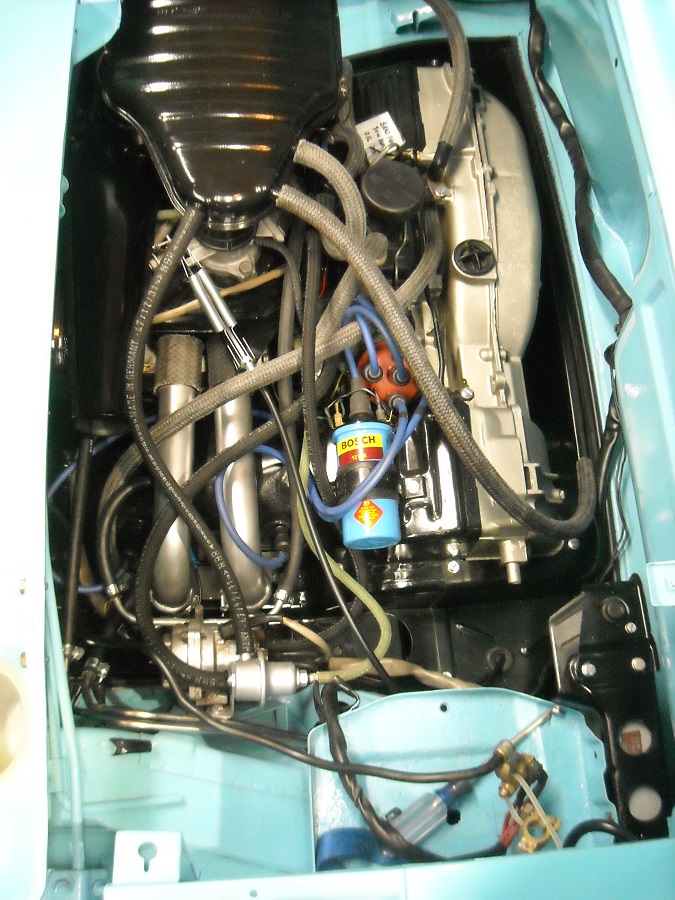
Posted by: bdstone914 Feb 10 2017, 09:00 AM
Does your distributor have one or two vacuum ports ?
And don't forget your screw driver on the battery tray.
Posted by: mgphoto Feb 10 2017, 09:32 AM
Good looking job, you will have some issues mixing and matching, dizzys, mps's and ecu's.
The ecu will determine how the vaccum lines are used.
One of the hoses is the vacuum retard and the other vacuum advance, that is the reason one of the nipples is above the diaphram and the other below.
Off the top of my head, I believe the 1.7 ecu is used with the 2.0l 73 FI, which requires the ballast resistor on the head temp sensor.
The 74 2.0l FI deletes the resistor and the vaccum retard, they cap the throttle body and leave the vacuum can unplugged.
'74 ecu and dizzy "vacuum can" are tuned. If you don't have the 2.0l dizzy your vaccum signature will not match the vaccum can response. You can either use a 2.0l dizzy or find a vaccum can that has a slotted screw with a locknut in the middle of the can, these can be adjusted to match the vacuum signature.
You will also need to turn the mps using an air / fuel ratio meter if you've increased the engine capacity.
Unless you have a concorse need, I would remove the deacceleration valve and cap the port on the plenum.
Just my 2 cents.
Good luck,
Mike
Posted by: Olympic 1.7 Feb 10 2017, 10:37 AM

Does your distributor have one or two vacuum ports ?
I have two ports on the distributor. The distributor is one of the original 73 1.7 parts.
Good looking job, you will have some issues mixing and matching, dizzys, mps's and ecu's.
The ecu will determine how the vaccum lines are used.
One of the hoses is the vacuum retard and the other vacuum advance, that is the reason one of the nipples is above the diaphram and the other below.
Off the top of my head, I believe the 1.7 ecu is used with the 2.0l 73 FI, which requires the ballast resistor on the head temp sensor.
The 74 2.0l FI deletes the resistor and the vaccum retard, they cap the throttle body and leave the vacuum can unplugged.
'74 ecu and dizzy "vacuum can" are tuned. If you don't have the 2.0l dizzy your vaccum signature will not match the vaccum can response. You can either use a 2.0l dizzy or find a vaccum can that has a slotted screw with a locknut in the middle of the can, these can be adjusted to match the vacuum signature.
You will also need to turn the mps using an air / fuel ratio meter if you've increased the engine capacity.
Unless you have a concorse need, I would remove the deacceleration valve and cap the port on the plenum.
Just my 2 cents.
Good luck,
Mike
I am using the 73 1.7 ECU (#037) and that was also used on the 73 2.0 .
I do have a variable POT that I will be using to determine the value needed for the ballast resistor inline from the CHT sensor.
Also I have a 043 MPS that was rebuilt and set to the 037 MPS specs that were used on the 73 2.0
I have tried to stay pretty true to the 73 2.0 FI setup, but I have made other changes to the engine, taking it to 2056, using HAM RS+ heads and a Raby 9590 cam.
I understand these changes may require a little fine tuning of the MPS and fuel pressure to get it to run correctly. I will be adding a Autometer Wideband AFR gauge to help in the tuning.
If both vacuum hoses were connected on the 73 2.0 setup I may just leave them hooked up. unless there is a negative effect to leaving the retard side connected.
Posted by: Jeff Bowlsby Feb 10 2017, 10:41 AM
That's pretty good advice but a couple of clarifications:
The two port throttle body is a 73 2.0L version, the 74 only has a single port - nothing to cap off on the 74 version.
It is better to keep the decel valve in place because it functions as a vacuum signal buffer to the MPS and offers no performance gain in taking it out. Removing it puts increased strain on the MPS diaphragm which is critical to the FI system.
Posted by: Olympic 1.7 Feb 10 2017, 10:42 AM
Unless you have a concorse need, I would remove the deacceleration valve and cap the port on the plenum.
Why that?
I did just clean that decal valve up and tested / adjusted it to open at about 17 in Hg
Posted by: brant Feb 10 2017, 04:09 PM
That's pretty good advice but a couple of clarifications:
The two port throttle body is a 73 2.0L version, the 74 only has a single port - nothing to cap off on the 74 version.
It is better to keep the decel valve in place because it functions as a vacuum signal buffer to the MPS and offers no performance gain in taking it out. Removing it puts increased strain on the MPS diaphragm which is critical to the FI system.
Jeff
I absolutely agree with you regarding keeping the decal valve in place on a FI car
I agree with your point about bleeding off excessive vacuum signal that could damage the MPS
and I am theorizing a 2nd reason for keeping the Decel valve in place:
that being that the excessive vacuum signal on decal, can cause the diaphragm to flex excessively, and would also change the mixture excessively. So the opening of the decal valve keeps the mixture closer to the max vacuum signal mixture that is programed into the stock settings.
1)protecting the diaphragm
2)limiting the mixture change on decal or high vacuum settings
these german engineers think of everything
brant
Posted by: poorsche914 Feb 10 2017, 09:45 PM
Have you taken a look at http://members.rennlist.com/pbanders/djetparts.htm?
Tons of information and should help you sort out what parts work best together.
Posted by: Olympic 1.7 Feb 11 2017, 01:31 PM
Concerning the Decel valve.
Just to add to the discussion / confusion is this 10 year old thread....
http://www.914world.com/bbs2/index.php?showtopic=67150&st=0
My experience when trying to set it was that if I blew into the side port it was very easy to tell when the valve opened using a mity-vac to provide vacuum to the control port.
HOWEVER.. If I blew into the end port it was not as obvious when the valve opened,
again providing vacuum to the control port using the mity-vac.
I don't understand this at all and just used the method of blowing into the side port to set the valve and then hooked it up with the side port to the air filter and the end port to the plenum.
Posted by: mgphoto Feb 11 2017, 01:35 PM
German's didn't think of everything. If the clamping device in the mps had the edge radiused the diaphrams might not crack as easily.If the German's were worried about the vaccum signal to the mps they would not have placed the ports in the plenum the way they did. This is not intended to be an argument, just some facts do what you will.
The de acel valve adds air into the mixture reducing hydrocarbons, so the engines would pass US emissions, only 2.0l euros have the valve, none of the 1.7 or 1.8 have it. This is sort of the same thing the Audi / VW engineers did to fool the emissions inspection.
You built a bitchin motor why gimp it to worry about a replacable part, I have a couple of spare mps's on my shelf ready to go if I run into a problem.
The vaccum retard is not your friend with a set up like yours, get Racer Chris's mps tuning kit and a spare diapham.
Again my 2 cents.
Mike
Posted by: Olympic 1.7 Feb 11 2017, 01:48 PM
I did rebuild my 043 MPS with one of Tangerines diaphragm kits. I used the 043 MPS to get the extra spacer below the diaphragm and then tuned it to the 037 spec in PB Anders site. Those specs were for the 73 2.0 MPS
Posted by: Bleyseng Feb 12 2017, 11:09 AM
You will have to tune the MPS even more to get it right using a 9590 cam but it should run just lean. Why are you trying to use a 037 ECU? If you find a 74 one all in all it should tune and run better as the 73 ECU has a few work arounds for the 2.0L engine
Posted by: Dave_Darling Feb 12 2017, 09:19 PM
The de acel valve adds air into the mixture reducing hydrocarbons, so the engines would pass US emissions, only 2.0l euros have the valve, none of the 1.7 or 1.8 have it.
This is incorrect. Most of the 1.7s, all US-spec 1.8s, as well as US-spec 2.0s, have decel valves. I believe the early 1.7s did not have them.
--DD
Posted by: GregAmy Mar 7 2017, 08:28 AM
Camping a relevant question onto this discussion thread...
'74 2L; no idea if it's early or late, but not germane to the question. When I got the car it wasn't running, hoses removed, ports capped off. AAR and decel valve not installed.
I'm slowly reinstalling equipment, and the decel valve is next. Fortunately I found one in the Box 'o Parts and it works, though I had to adjust it WAY out to get it to move at the 17 inHg that Anders suggests. It appears I need to get some 10mm hose, and I see that there's 10mm ports on the airbox and plenum (both of which are plugged now), so I'm good there.
However, in the Post #1 drawing the decel valve vac control line appears to go to a fitting on the right front of the plenum, and the diagram shows some kind of tee fitting there. I don't have that on my car, it's also plugged off. Does anyone know the size of that plenum fitting, and if that tee is required? Can I tee into the distributor vac line to control the decel valve?
For reference, on my car the PCV hose off the oil fill is going directly into the airbox, where the AAR goes into in the drawing. Is that correct? Do we allow the to pull air directly from the crankcase ventilation into the intake plenum? Isn't that a very big vacuum leak?
Finally, my distributor may be routed incorrectly. The inside vac line (orange circle in the drawing in Post #1) is going to one of the vac fittings on the throttle body, but the outside vac line (blue circles) is going to a vac line fitting on the opposite side of the throttle body. I can't tell in the drawing where the blue-circle line is supposed to go on the plenum?
So, TL;DR:
- What is that tee fitting where PCV and decel valve vac line go to, and if it's needed where do I get one?
- Is the fitting on the plenum where that tee goes into 10mm? Can I just go directly to that?
- Can I tee off the distributor vac line to control the decel valve?
- Where does the outer side of the distributor vac canister go to on the plenum?
Edit: to add to my grief...I just pulled the plug off the 10mm port on the plenum, and someone had trimmed the length! It's only about 1/4" long now, which explains why it was being held on with a hose clamp. Dammit, why do people do stuff like that???
Posted by: mgphoto Mar 7 2017, 02:43 PM
The de acel valve adds air into the mixture reducing hydrocarbons, so the engines would pass US emissions, only 2.0l euros have the valve, none of the 1.7 or 1.8 have it.
This is incorrect. Most of the 1.7s, all US-spec 1.8s, as well as US-spec 2.0s, have decel valves. I believe the early 1.7s did not have them.
--DD
The only euro cars to have the de acel valve was 2.0l none of the 'EURO" 1.7's and 1.8's had the valve. sorry I was not clear.
Buy the way all euro 1.8's had dual cards.
Check the parts book, lots of info there.
Posted by: Shredhead Mar 15 2017, 02:27 PM
Also jumping on this thread... I have a late '74 2.0 with Djet. The advance port on the dizzy is plugged off at the dizzy and the retard has the vacuum line on it. I'm assuming it's correct to have the advance plugged? When I go to do the timing at 3500 RPM, should I have the retard plugged also, or does that even matter?
Posted by: The Cabinetmaker Mar 15 2017, 04:25 PM
Remove and plug both hoses for timing.
Posted by: Olympic 1.7 Mar 16 2017, 04:19 PM
Camping a relevant question onto this discussion thread...
'74 2L; no idea if it's early or late, but not germane to the question. When I got the car it wasn't running, hoses removed, ports capped off. AAR and decel valve not installed.
I'm slowly reinstalling equipment, and the decel valve is next. Fortunately I found one in the Box 'o Parts and it works, though I had to adjust it WAY out to get it to move at the 17 inHg that Anders suggests. It appears I need to get some 10mm hose, and I see that there's 10mm ports on the airbox and plenum (both of which are plugged now), so I'm good there.
However, in the Post #1 drawing the decel valve vac control line appears to go to a fitting on the right front of the plenum, and the diagram shows some kind of tee fitting there. I don't have that on my car, it's also plugged off. Does anyone know the size of that plenum fitting, and if that tee is required? Can I tee into the distributor vac line to control the decel valve?
For reference, on my car the PCV hose off the oil fill is going directly into the airbox, where the AAR goes into in the drawing. Is that correct? Do we allow the to pull air directly from the crankcase ventilation into the intake plenum? Isn't that a very big vacuum leak?
Finally, my distributor may be routed incorrectly. The inside vac line (orange circle in the drawing in Post #1) is going to one of the vac fittings on the throttle body, but the outside vac line (blue circles) is going to a vac line fitting on the opposite side of the throttle body. That's how mine is set up I can't tell in the drawing where the blue-circle line is supposed to go on the plenum? In that diagram its just tucked under the plenum and not connected
So, TL;DR:
- What is that tee fitting where PCV and decel valve vac line go to, and if it's needed where do I get one? I got a plastic universal T fitting from the hardware store
- Is the fitting on the plenum where that tee goes into 10mm? Can I just go directly to that? Yes
- Can I tee off the distributor vac line to control the decel valve?
- Where does the outer side of the distributor vac canister go to on the plenum? [/color] On the 74s there was not a fitting on the throttle body for the retard side of the vacuum, the line attached to it was just tucked under the plenum and left open
Edit: to add to my grief...I just pulled the plug off the 10mm port on the plenum, and someone had trimmed the length! It's only about 1/4" long now, which explains why it was being held on with a hose clamp. Dammit, why do people do stuff like that???
This is just how mine is setup, more knowledgeable people may give you other advice on how to proceed.
Posted by: Mark Henry Jan 15 2021, 04:54 PM
What is the correct placement for the T in the fuel line for the CSV cold start valve fuel line?
I take it it's suppose to have a steel pipe T fitting, not the shiny brass hardware store T fitting that's in there right now.
Posted by: Olympic 914 Jan 16 2021, 07:26 AM
this thread was mainly about the vacuum lines.
But in my setup I have the fuel line for the CSV coming off the tap on the 1-2 fuel rail. 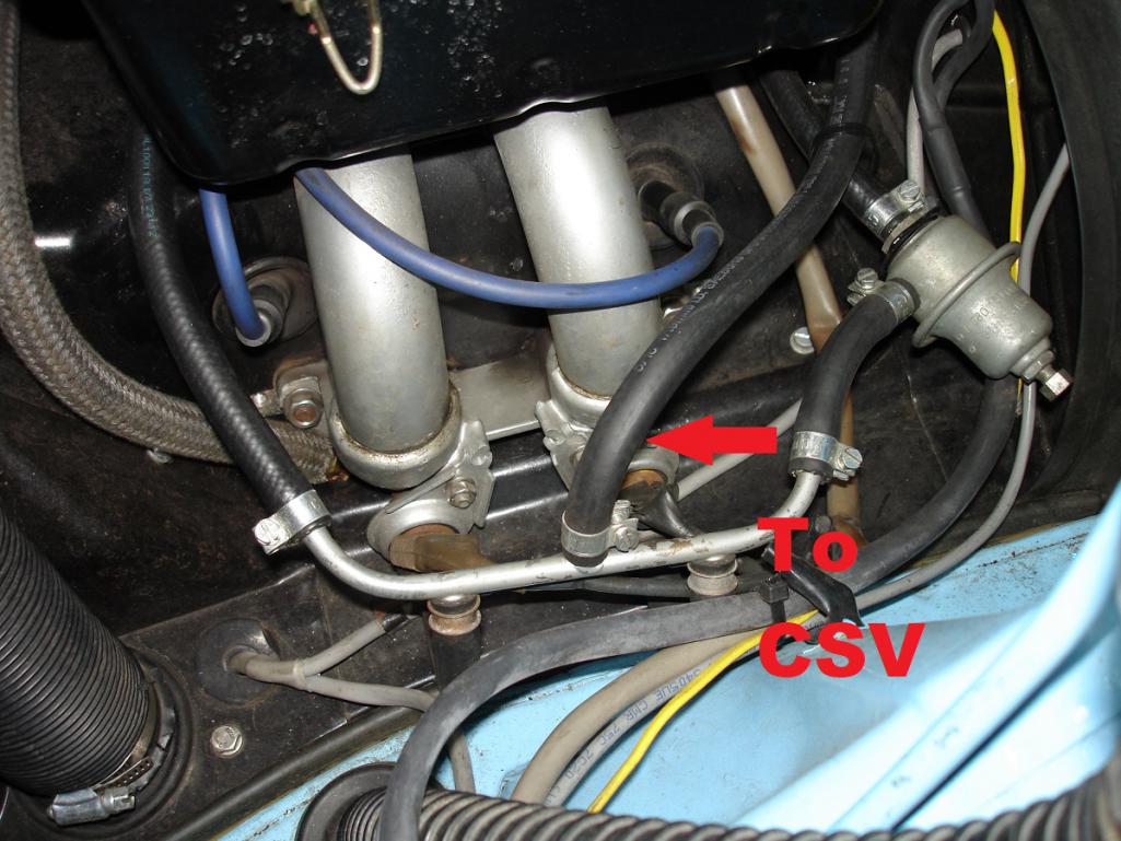
Posted by: GregAmy Jan 16 2021, 09:52 AM
Yup. CSV line comes off the left fuel rail. Right fuel rail has a little screw in it.
You drive it in freezing weather? The CSV isn't activated above ~32F/0C. I eventually removed mine entirely.
Posted by: Stratfink Dec 4 2022, 02:14 PM
Getting ready for a throttle body rebuild and planning to use a spare core, but noted a difference in my spare relative to the part installed in my 75 2.0L.
My installed throttle body has 2 vacuum ports which I understand are for the vacuum advance and retard (I actually found the advance line loose at the distribution vac can).
I am looking to confirm that the best course of action is to retain the dual ported throttle body versus rebuilding the single port body and capping the retard line at the distributor. Pretty new to this so I appreciate the feedback to confirm.
Pics of my installed and spare bodies are below.
Installed on my ‘75 2.0L: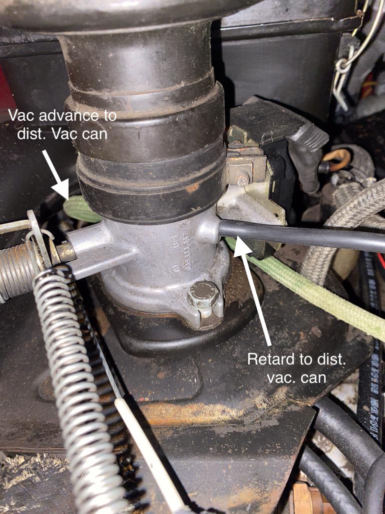
Spare throttle body: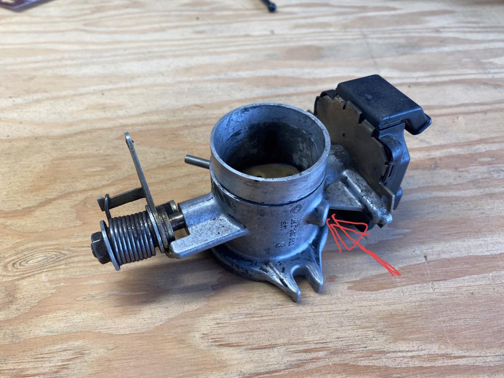
Posted by: wonkipop Dec 4 2022, 03:24 PM
@http://www.914world.com/bbs2/index.php?showuser=26198 i suspect this is a bit similar to the L jets.
D Jet experts like @http://www.914world.com/bbs2/index.php?showuser=104 will chime in - they know for sure.
74 49 state L Jet 1.8s had the dual port throttle body hooked up to both the vac advance and retard sides of dist. vac retard went to idle port on TB. vac advance went to port in front of throttle plate.
the vac retard dealt with emissions at idle basically. lowered NOX. but ran hotter at idle.
the advance gave fuel economy and cooler running at cruise. did nothing for emissions.
the 74 cali L Jet had single port throttle body (or one of the ports capped).
only the vac retard was hooked up to the throttle body. (to idle port).
this meant lowered NOX and idle and additional slightly retarded ignition timing at cruise.
lower NOX hotter running at cruise.
california had higher emission standards in 74 than 49 states.
in 75, the 49 state L Jet ran the 74 californnia set up.
and the california 1.8 hooked up the EGR to the port on throttle body in front of throttle plate. the calif set up gave lower NOX at idle via the ignition timing, the EGR restored fuel economy and cooler running at cruise despite the slightly retarded timing, which served to lower NOX.
i imagine its similar for the D Jets.
though i am not sure it was split between 49 states and california like it was for L jets.
the double vac can distributor and ignition timing played a large part in emissions control during those years.
there is a bit more detail in the 74 L Jet thread in the originality section of this website.
it took us a bit to work it all out for the L jets.
Posted by: hndyhrr Dec 4 2022, 07:43 PM
The de acel valve adds air into the mixture reducing hydrocarbons, so the engines would pass US emissions, only 2.0l euros have the valve, none of the 1.7 or 1.8 have it.
This is incorrect. Most of the 1.7s, all US-spec 1.8s, as well as US-spec 2.0s, have decel valves. I believe the early 1.7s did not have them.
--DD
I have a 70,.17 fi, build date april 70. I have decel valve
Posted by: 914sgofast2 Dec 4 2022, 08:03 PM
I have a 1970 1.7liter without the deceleration valve. The car has a December 1969 build date. Wonder when the factory added it during the early production run?
Posted by: JeffBowlsby Dec 4 2022, 10:29 PM
Decel valve was added in 1972. Could be retrofitted to earlier cars.
Posted by: JamesM Dec 4 2022, 11:57 PM
I am using the 73 1.7 ECU (#037) and that was also used on the 73 2.0 .
I do have a variable POT that I will be using to determine the value needed for the ballast resistor inline from the CHT sensor.
Also I have a 043 MPS that was rebuilt and set to the 037 MPS specs that were used on the 73 2.0
I have tried to stay pretty true to the 73 2.0 FI setup, but I have made other changes to the engine, taking it to 2056, using HAM RS+ heads and a Raby 9590 cam.
So, its more than just an inline resistor that makes the 1.7 ECU work with the early 73 2.0s, the head temp sensor itself was also unique to that application. You can futz with all the variable resistance you like to get it running good when fully warm but the entire resistance curve is different so warm up mixture is always going to be an issue unless you can find a 0 280 130 017 sensor. These days though it might be easier to just find a 74 or 75 ECU.
Posted by: wonkipop Dec 5 2022, 02:18 AM
pay attention
@http://www.914world.com/bbs2/index.php?showuser=16332
@http://www.914world.com/bbs2/index.php?showuser=15855
@http://www.914world.com/bbs2/index.php?showuser=5834
this is a very old thread, you are responding to the wrong person back in time.
@http://www.914world.com/bbs2/index.php?showuser=26198 is coming in on old thread and asking a very specific question about vac lines from the distributor to the throttle body on a D jet 2.0
@http://www.914world.com/bbs2/index.php?showuser=104 - you must know the answer to @http://www.914world.com/bbs2/index.php?showuser=26198 's question.
i know enough from searching out the very same question in relation to L jet throttle bodies linked to distributors to know that there were 4 different throttle bodies, (theorectically) for the 74 and 75 L jets according to the PET. but those part numbers do not come up as stamps on the throttle bodies. they all just have the same number sequence cast in but not the variant letters that come after the 9 digit part number.
and i've seen the same thing goes for the D jet 2.0 throttle bodies.
they D jets have the same throttle body as far as i can tell for 73 and 74 if you look at the PET. but there are two different throttle bodies for 75 on. one for calif and one for 49 states. i suspect its to do with how you hook up the vac hoses from the distributor.
the question that @http://www.914world.com/bbs2/index.php?showuser=26198 is asking. is he not?
i don't know about D jets.
but if the same question was asked of me about L jets this would be my answer.
all the L jets can be turned into any of the variants by simply plugging or unplugging the hoses, but you do need to have both ports on the throttle body.
and they all had the retard hose from the distributor hooked up to the throttle body.
it was the advance hose that was either plugged in or not plugged in.
in the case of L jets, if someone said which was the best i would not hestitate to say the 74 49 state. with the vac hoses all hooked up.
why.
because the 74s ran the same ECU. all they did was unplug the hose on the californian cars to make them run at cruise retarded slightly and run hotter, purely for emissions.
it was a dumb as that.
D jet. i don't know about. but i would suspect it was similar?
but i could be way wrong because i really don't know much about D jet.
Posted by: JeffBowlsby Dec 5 2022, 10:15 AM
I had answered this previously in this same thread:
"The two port throttle body is a 73 2.0L version, the 74 only has a single port - nothing to cap off on the 74 version"
The ignition advance was not connected to the throttle body on the 74-76 2.0L cars. From the factory, a short length of hose ran from the advance port and was routed under the air plenum not connectoed to anything, which is what my diagram depicts
Posted by: wonkipop Dec 5 2022, 05:42 PM
I had answered this previously in this same thread:
"The two port throttle body is a 73 2.0L version, the 74 only has a single port - nothing to cap off on the 74 version"
The ignition advance was not connected to the throttle body on the 74-76 2.0L cars. From the factory, a short length of hose ran from the advance port and was routed under the air plenum not connectoed to anything, which is what my diagram depicts
good stuff mr. b
interesting the D jets were just like the L jets then.
makes sense.

in that state with the retard hose only the distributor will retard the ignition whenever there is engine vacuum.
thats either with the throttle closed at idle or when the engine is part open throttle at cruise or deaccelerating with the throttle snapped shut.
when the advance hose is hooked up it can only affect the distributor when the throttle is open. you get engine vacuum at cruise that will operate that side of the can.
the total advance is a nett figure. vac can advance - vac can retard = total vac advance added to mechanical (centrifigal) advance.
thats the way it works. thats why the vac advance side of the can is larger than the retard side.
hence my view that the versions which utilise both sides of the can -
that would be a 73 2.0 (thanks mr. b) and a 74 49 states L jet - are probably better from a driveability fuel economy point of view. you would have to drive the two versions side by side to notice the difference and i'm guessing its really only detectable out on the highway at cruise. you would get better fuel mileage and probably run a little cooler.
Posted by: JeffBowlsby Dec 5 2022, 07:08 PM
In the wild and crazy portion of my mis-spent youth I once tried the 1973 2 port TB vs the stock 1-port on my 74 2.0L 'performance upgrade'
The performance difference was awfully subtle. Maybe in a lab hooked up to wires and test equipment there is a difference but not the butt dyno. Underwhelmed if not unnoticeable.
Posted by: wonkipop Dec 6 2022, 06:12 PM
In the wild and crazy portion of my mis-spent youth I once tried the 1973 2 port TB vs the stock 1-port on my 74 2.0L 'performance upgrade'
The performance difference was awfully subtle. Maybe in a lab hooked up to wires and test equipment there is a difference but not the butt dyno. Underwhelmed if not unnoticeable.
the old butt dyno would be fully trustworthy.

its easy enough to do on a L jet. i guess i should try some time. pull out the advance hose and plug the throttle body and see what happens. too lazy. car runs too nice.
might upset the apple cart. but i'm think i won't even notice the difference driving around town. not like there is any steady state cruising highways around here - even the freeways are clogged with stop and start traffic post covid.

Powered by Invision Power Board (http://www.invisionboard.com)
© Invision Power Services (http://www.invisionpower.com)