Printable Version of Topic
Click here to view this topic in its original format
914World.com _ 914World Garage _ Replacement Relay Socket Panel
Posted by: Evan0 Apr 30 2017, 10:12 AM
http://www.914world.com/bbs2/index.php?s=&showtopic=309222&view=findpost&p=2517111
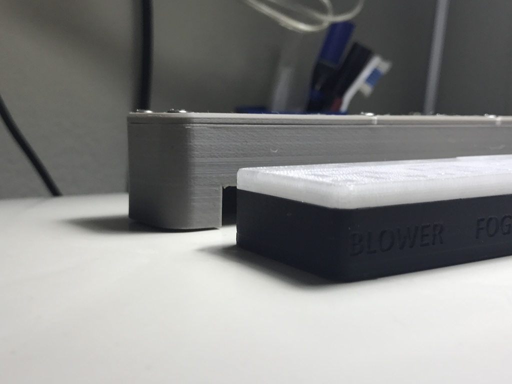
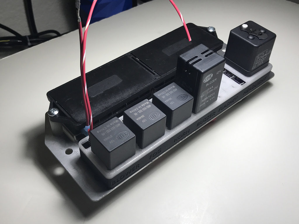
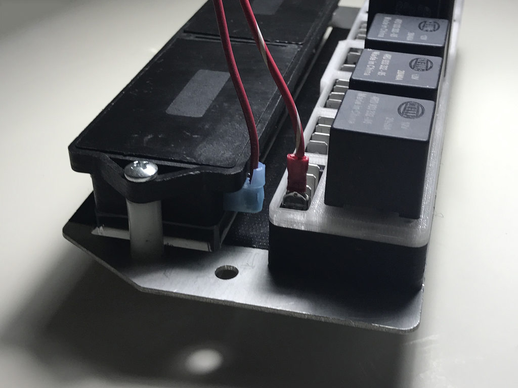
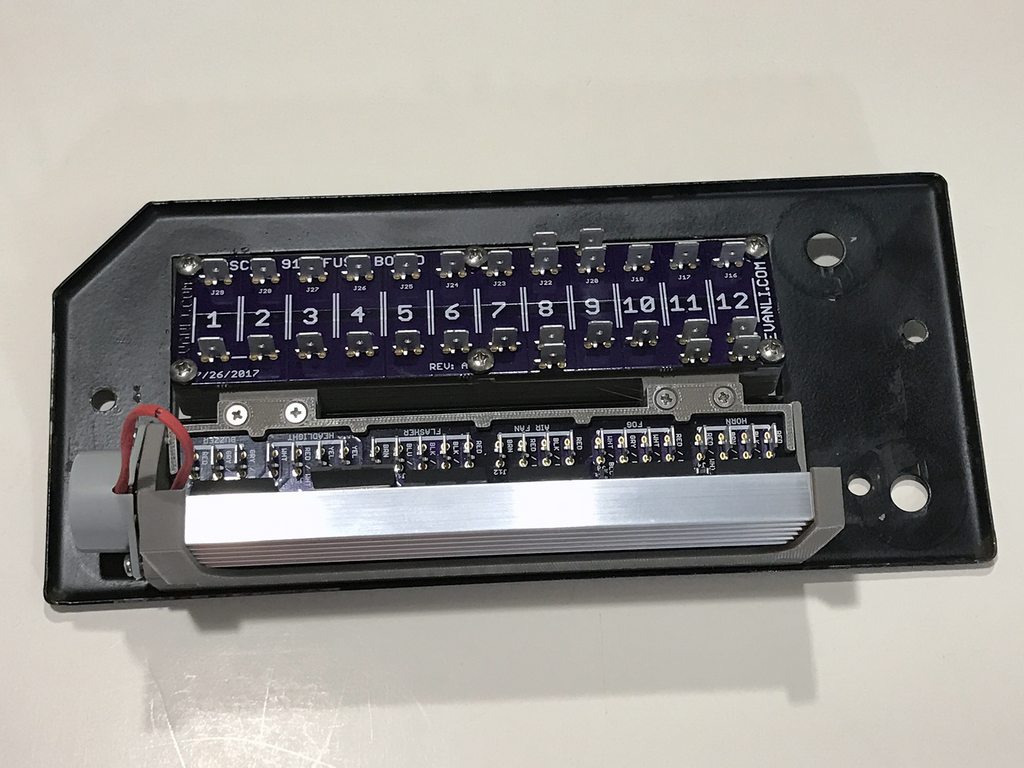
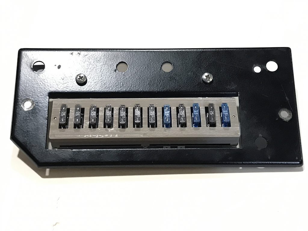
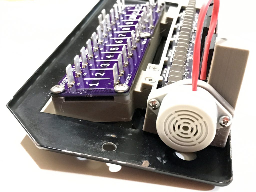
I've been rewiring my car for the last few weeks and part of that was replacing the factory fuse panel with one that uses modern fuse from JWest Engineering. I was unhappy with the existing relay sockets that I found. As a result of that, I designed and printed a monolithic fuse socket for all the relays, buzzer, and flasher unit. 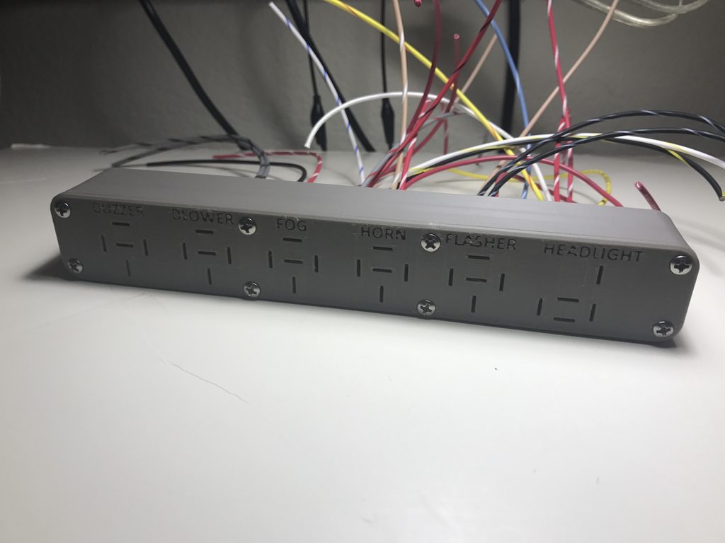
After mounting it to the fuse panel. The buzzer is a Hella H35394001. The horn, blower, and fog relays are Hella 933332051. The flasher unit is a Hella 009492101. The head light relay is a modern reproduction of the VW one. Still waiting on the flasher unit to ship. 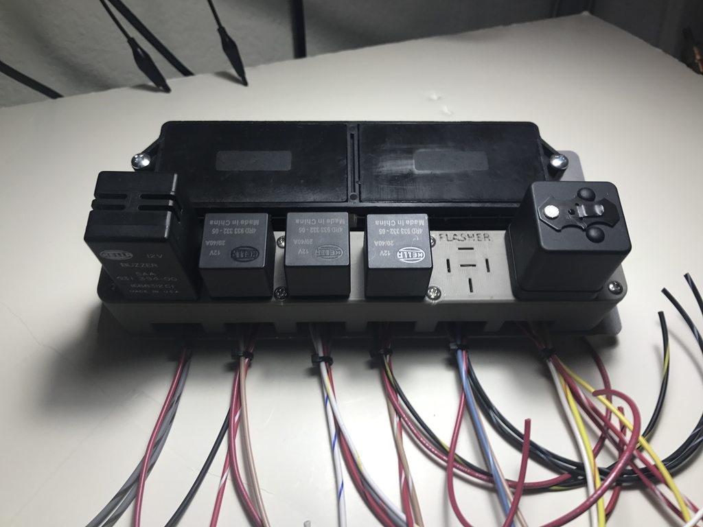
I'll be posting the STL files, Bill of Materials, and instructions after I've worked out a few kinks. I would love any feedback or suggestions on improvements.
Posted by: mepstein Apr 30 2017, 10:35 AM
That looks great! How much would you charge to make one or a couple? I would like to buy. Thanks, mark
Posted by: Evan0 May 1 2017, 09:34 AM

That looks great! How much would you charge to make one or a couple? I would like to buy. Thanks, mark
I'm working on a improved version. I wasn't happy with the clearance for wire routing underneath the dash with it installed. I'll update when new version is ready.
Posted by: mepstein May 1 2017, 09:46 AM
That looks great! How much would you charge to make one or a couple? I would like to buy. Thanks, mark
I'm working on a improved version. I wasn't happy with the clearance for wire routing underneath the dash with it installed. I'll update when new version is ready.
Awesome. Keep me in touch please.
Posted by: BillC May 1 2017, 11:29 AM
I am also interested.
Posted by: JoeD May 1 2017, 11:35 AM
Love it. I'd be down for one too. I've got the JWest fuse block and solid state relays in the engine bay... this would complete the trifecta!
Please let me know if you get to making more.
Posted by: jd74914 May 2 2017, 11:06 PM
Very cool! Great idea as well. I'm quite interested; the old relays with their worn sockets always bothered me.
If you don't mind sharing-material and printer? The surface finish is better than any SLA machine I've seen and almost every SLS. 
Posted by: euro911 May 2 2017, 11:19 PM
Nice innovation 
Posted by: plymouth37 May 2 2017, 11:47 PM
Heck yeah! Nice work!
Posted by: GeorgeRud May 3 2017, 08:09 AM
Thanks for posting! As the round relays are getting more expensive, a cheap, modern alternative would be great. I love seeing this new technology applied to older cars.
Posted by: Evan0 May 3 2017, 08:24 AM
Very cool! Great idea as well. I'm quite interested; the old relays with their worn sockets always bothered me.
If you don't mind sharing-material and printer? The surface finish is better than any SLA machine I've seen and almost every SLS.
It's Zortrax ABS printed on a Zortrax M200. Most reliable printer I've ever used.
Posted by: john77 May 3 2017, 11:50 AM
This is great. Definitely interested in one.
Posted by: NS914 May 3 2017, 12:26 PM
Hi EvenO,
As the others have noted below....I would take one in a heart beat!
I too have installed my JWest Fuse Panel in as well.....those old relays are a nightmare...I still have not figured out how to get them to fit in the panel....your set up would be fantastic. Regards, Grant
Posted by: Evan0 May 19 2017, 04:35 PM
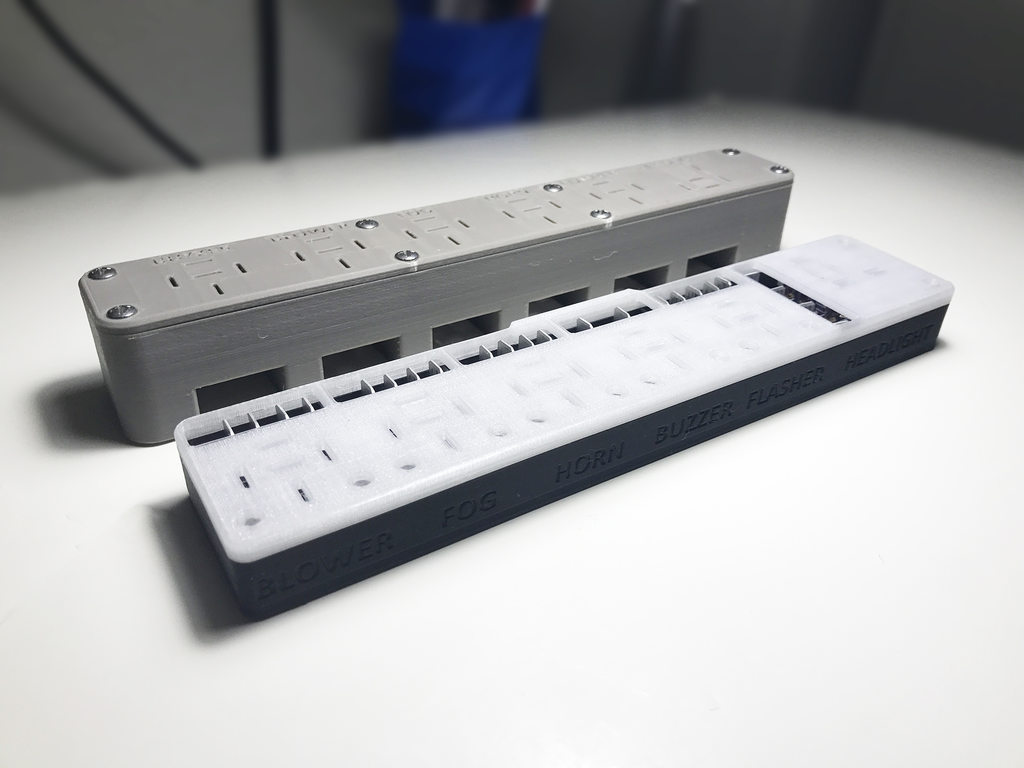
After a few weeks of redesign, I have a relay solution that i'm happy with. Not only is it more compact, it's modular so i can be reused for other applications. Not sure if I'm going to have the resource to produce these in quantity, but i'm looking into the possibility. I would love any feedback or suggestions on improvements.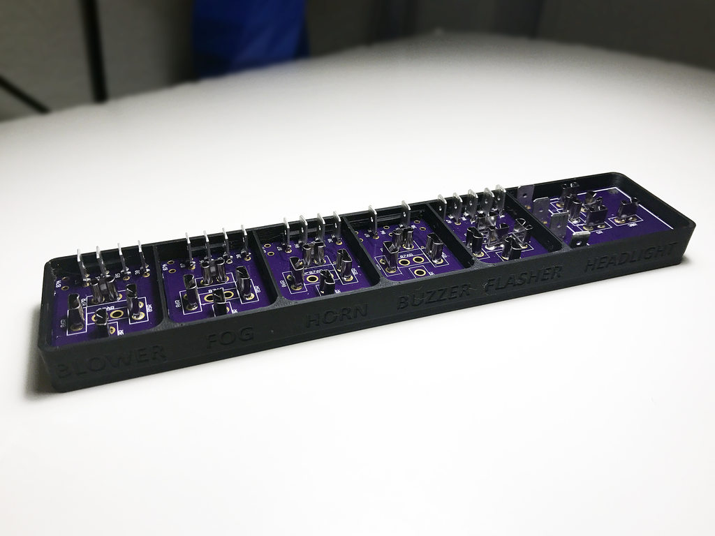
Posted by: Jeff Bowlsby May 19 2017, 05:28 PM
What does the side facing the cabin floor look like?
Posted by: Evan0 May 19 2017, 05:35 PM
What does the side facing the cabin floor look like?
Posted by: porsche913b_sp May 19 2017, 06:30 PM
That's cool, I would be interested in one too 
Posted by: clapeza May 19 2017, 07:04 PM
Beautiful and functional!
Put me on the list!
Any chance of turning your attention to the engine compartment relay board?
Chester
Posted by: Jeff Bowlsby May 19 2017, 07:38 PM
I generally have concerns about the so-called 'upgraded' panels because many have proven to be problematic discovered only after a short amount of use. This set-up seems to have some positives.
The custom relay mounting base seems well done and using the new relays and fuses is commendable.
Don't like the cheapo side mount fuseblocks because attaching the chassis harness wiring stresses the wiring- using the flag terminals may address the tight fit but that means that all the original terminals need replacement.
PLEASE do not promote using those cheesy insulated terminals. Locate some solid brass double barrel terminals in the appropriate wire gauges as needed without the plastic insulator - because they are not a good long term solution.
Posted by: bandjoey May 19 2017, 08:20 PM
If you don't want to be a manufacture then license it to 914rubber for a % This could be a several thousand unit order when promoted.
Posted by: Evan0 May 19 2017, 11:43 PM
I generally have concerns about the so-called 'upgraded' panels because many have proven to be problematic discovered only after a short amount of use. This set-up seems to have some positives.
The custom relay mounting base seems well done and using the new relays and fuses is commendable.
Don't like the cheapo side mount fuseblocks because attaching the chassis harness wiring stresses the wiring- using the flag terminals may address the tight fit but that means that all the original terminals need replacement.
PLEASE do not promote using those cheesy insulated terminals. Locate some solid brass double barrel terminals in the appropriate wire gauges as needed without the plastic insulator - because they are not a good long term solution.
Thanks for the advice regarding the terminals. I'll find the right flag terminals for final installation. Do you happen to know any of the troubles people have after replacing the panel? I would love to nip those in the bud before I run into them.
Addressing the replacement of all the terminals, my harness was mutilated by one of the previous owners, and everything under the dash had to be rewired and re-terminated. I don't have the resources to removed the entire harness and try to replace it with one in better condition. This is complicated by the fact that my car has had a LS1 swap and the electrical wiring is a bit iffy on the documentation.
This solution was designed primarily for my needs and definitely need further refinement before anyone else tries to use it. Suggestions and input like this is much appreciated.
Posted by: Jeff Bowlsby May 20 2017, 07:55 AM
The main issues I see are that:
1. The new fuse block mount on another version (not yours) had a metal strap that would short against the power terminal block on the 1970-72 cars.
2. The new stress put on the wiring to wire terminal juncture because of the side terminal locations rather than the original rear mount locations at the fusepanel. The ties organizing the wiring at the fuseblock needs to be loosened up or removed to give enough slack to connect the wires to their new side mount location. Stress on the wires over time will cause the wiring to fail at that stress point.
3. The new fuseblocks do not have the bussed together lugs that the factory fuseblocks do, so makeshift additional terminal busses are needed or the circuitry is altered to accommodate, making the factory wiring schematic useless for troubleshooting.
4. How well made are the new fuse blocks? The ones I have seen are of poor quality relative to the bakelite shell and solid brass fuse terminals of the factory original fuse blocks.
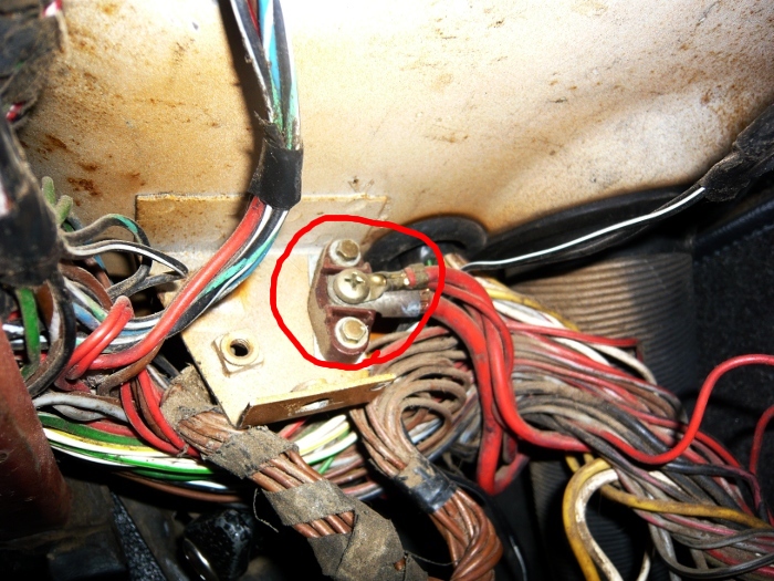
People have been replacing the original fuse blocks to use the new style fuses and because some say that they repeatedly kick out the fuses when getting in/out of the car. In 40 years of driving 914s, I have never had any issues with the original fuse blocks. I don't see any benefit to change the fuse block, personally.
Attached image(s)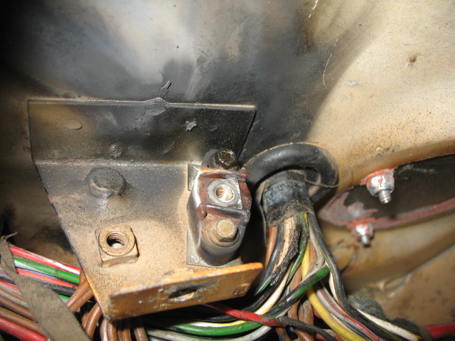
Posted by: Evan0 May 20 2017, 11:41 AM
The main issues I see are that:
1. The new fuse block mount on another version (not yours) had a metal strap that would short against the power terminal block on the 1970-72 cars.
2. The new stress put on the wiring to wire terminal juncture because of the side terminal locations rather than the original rear mount locations at the fusepanel. The ties organizing the wiring at the fuseblock needs to be loosened up or removed to give enough slack to connect the wires to their new side mount location. Stress on the wires over time will cause the wiring to fail at that stress point.
3. The new fuseblocks do not have the bussed together lugs that the factory fuseblocks do, so makeshift additional terminal busses are needed or the circuitry is altered to accommodate, making the factory wiring schematic useless for troubleshooting.
4. How well made are the new fuse blocks? The ones I have seen are of poor quality relative to the bakelite shell and solid brass fuse terminals of the factory original fuse blocks.
People have been replacing the original fuse blocks to use the new style fuses and because some say that they repeatedly kick out the fuses when getting in/out of the car. In 40 years of driving 914s, I have never had any issues with the original fuse blocks. I don't see any benefit to change the fuse block, personally.
Thanks for the info. I was wondering if that terminal block for battery power was factory or not. I will try to properly strain relief the wires as they are managed, but your right that it will eventually be an issue due to the tight spacing. The JWest blocks seems to be of good quality and it looks like the terminal blocks are properly bused together for 1-2, 3-4, and 10-12.
For the flag connectors, I'm going with the Molex Vibrakrimp series of connectors. They have a insulation grip, which will help offload some stress from the conductor itself. Again, thanks for the insight, you and your site are invaluable resources.
Posted by: mepstein Jul 15 2017, 11:28 AM
Any updates. I'm still interested. Thanks, mark
Posted by: Bartlett 914 Jul 15 2017, 11:46 AM
That is the best conversion I have seen. I hope you don't drop the project. Jeff offered some objective criticism which should help make this the perfect upgrade.
Posted by: 914Sixer Jul 15 2017, 11:55 AM
I( agree with Jeff about the flag connectors. Can you simply turn the fuse block around and face the spades to the rear? Looks like that would be straight forward move and a solution to the problem.
Posted by: Evan0 Jul 16 2017, 10:49 PM
I've just gotten my car going again this weekend, and have some changes and improvements that can be made. The board worked, but the current design had some problems during installation, and isn't suitable as a drop in replacement. I have plans for the next iteration that will hopefully be good enough to see the light of day on another 914. Thanks for the patience and constructive input, much appreciated.
Posted by: NS914 Jul 17 2017, 11:17 AM
Hey Evan, I am actually into this right now and have been having a heck of a time to get my existing relays should back into the holes in the J West panel...your engineering and initiative would be just the ticket!
I see that after going through a few iterations you continue to develop it. Please put me on your list of future "me too" people.
Regards, Grant
Posted by: raynekat Jul 19 2017, 08:30 PM
I have to agree with Jeff Bowlsby on the after market fuse panels.
I'm doing a 914-6 conversion on my 1971 914-4 and I'm using an NOS 1971 chassis wiring harness.
I've also got a JWest aftermarket fuse panel.
The way this panel works is that the wires on the "inlet" and "outlet" sides of the fuse come in on opposite sides of the panel.
Where in the factory panel, the "inlet" and "outlet" wires come in on the same side of the fuse panel.
THAT IS A BIG DIFFERENCE WHEN IT COMES TO PLUGGING ALL THESE WIRES IN.
I'm seeing that there is a lot of stress on the connectors with the JWest panel and the main harness kind of straddles the panel vs being in behind the panel with the factory setup.
So I've decided to ditch the JWest with the new style fuse in lieu of the old fashioned factory style.
I can just tell the factory will be a much better setup.
Obviously the factory knew what it was doing.
Posted by: raynekat Jul 24 2017, 05:35 PM
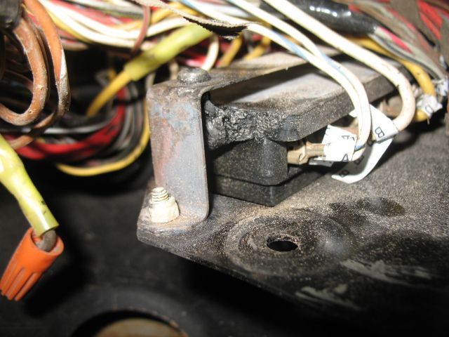
This gives you an idea.
On the factory fuse panel, both the incoming and outgoing wires come from approximately the same direction from the main wiring bundle.
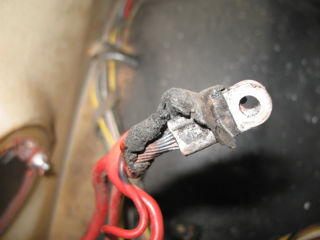
(A) On the after market panels, the incoming wires must loop around to the backside of the connection block.
It seems like this would put a lot of stress on the wire/connector on that side of connection block.
These incoming wires are just not long enough coming out of the main wiring bundle to make the journey relatively stress free.
(B) One option is to move the main wiring bundle such that it straddles the connection block, but again the direction change that both the incoming and outgoing wires make from the main wiring bundle to the connection block is not idea.
In the end, I've decided to stick with my 40 year old factory fuse block design and live with archaic fuse technology.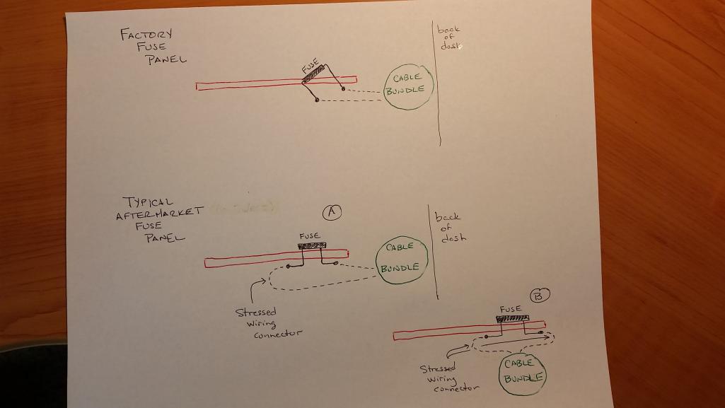
Posted by: rad23racer Jul 24 2017, 11:31 PM
I've just gotten my car going again this weekend, and have some changes and improvements that can be made. The board worked, but the current design had some problems during installation, and isn't suitable as a drop in replacement. I have plans for the next iteration that will hopefully be good enough to see the light of day on another 914. Thanks for the patience and constructive input, much appreciated.
I’m in Corona and would like to offer to help with this project. I have CNC and 3D printing available to me as well. In addition, my car is mostly disassembled so things are easy to get to.
Posted by: Evan0 Jul 25 2017, 12:38 PM
Thanks for the input everyone. I have a drastically different approach to the problem than my original design. It should end up being a much better permanent solution as well as lowering the overall cost. I'm also working on replacing the existing fuse block as well with one better suited to the cable organization. I should have a couple units ready to test in a couple weeks if anyone wants to be a guinea pig.
Posted by: Evan0 Aug 14 2017, 10:17 PM
It's been a few weeks and the first prototype for version 3 are complete. First some background on why version 3 is so drastically different. Between the combination headlight relay, buzzer and other relays, the cost for just the relays was easily over $100. The LED flasher unit from Hella took over 3 months from when I first ordered it to when it arrived. Also the sheer size of the relays and its mount weren't great for placement or installation.
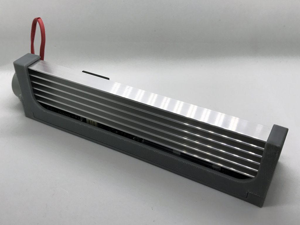
Version 3 consists of a completely custom solution for all the components needed to run a 914. The combination relay, flasher and buzzer are all replicated using discrete logic and solid state relays. The relays are rated for 60 volts and up to 40A peak and 32A continuous. Best part of the this design is that even at a single unit it only costs about $70. 
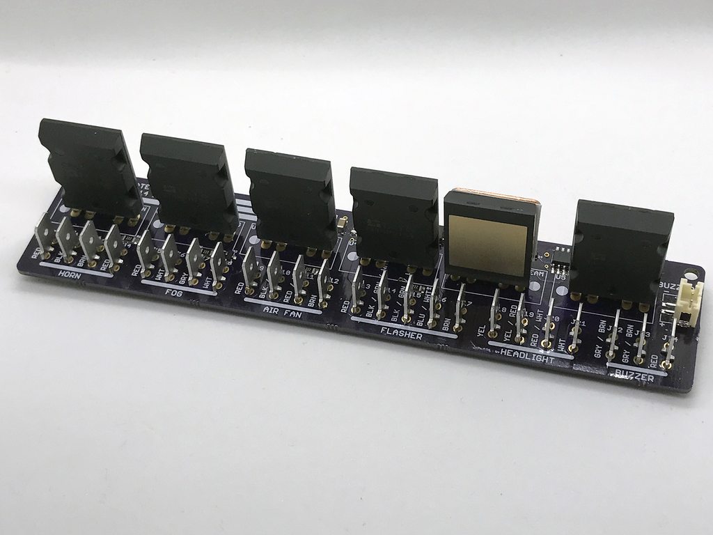
The relay board assembly is designed fit with its heatsink to the JWest fuse panel.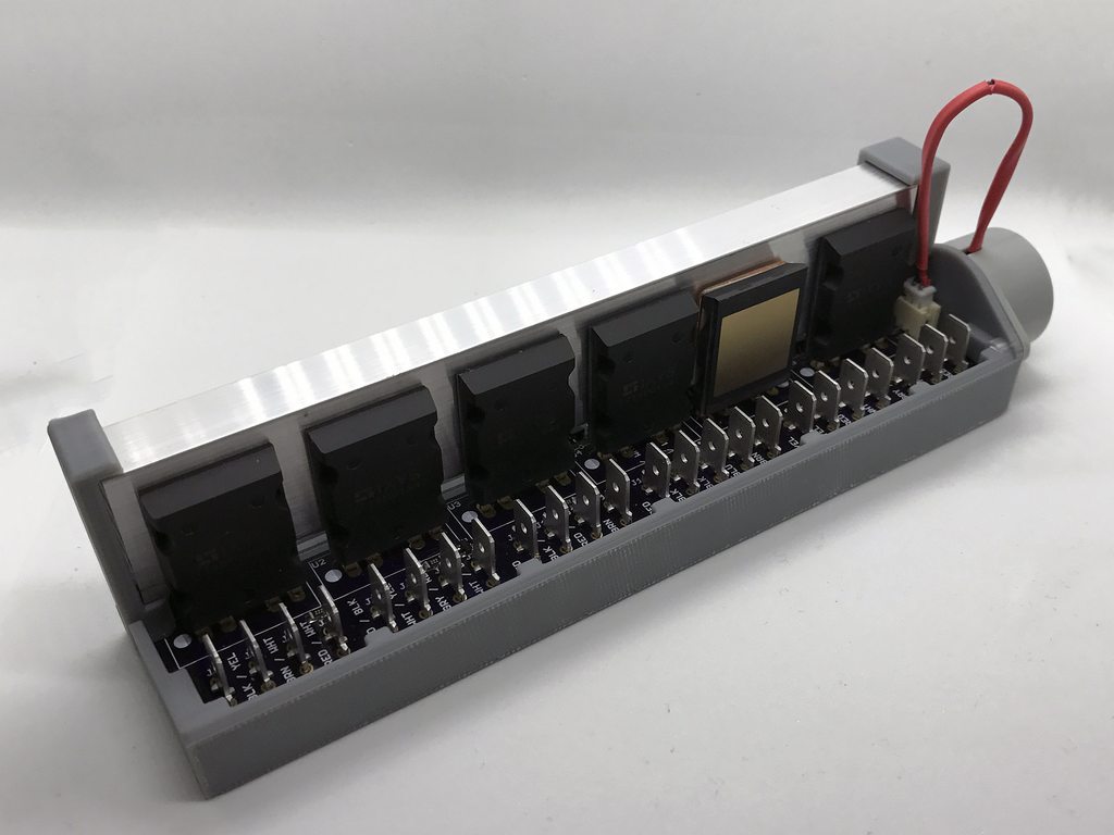
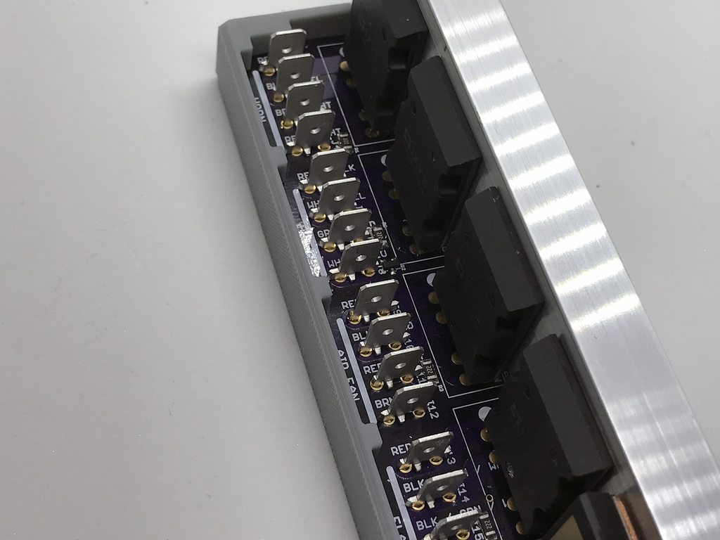
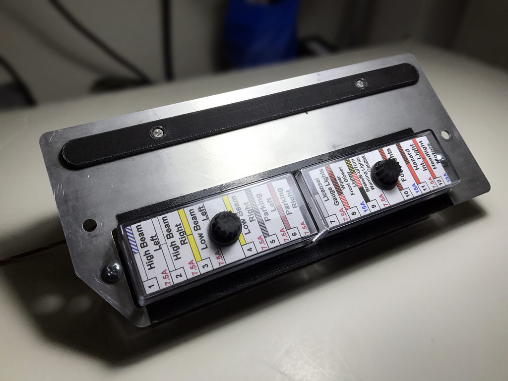
Since I heard a lot of complaints about the JWest panel, I thought I would take a stab at the problem. The terminals emulate the factory panel, with the correct terminals bused together, and it includes the tilt toward the front of the car. It uses standard ATO fuses. This piece would replace the factory fuse block and integrates my new solid state relay solution. A 1.5mm laser etched plate would sit on the front of the fuse block and provide markings and indication. I didn't get that done in time, but it's not critical. 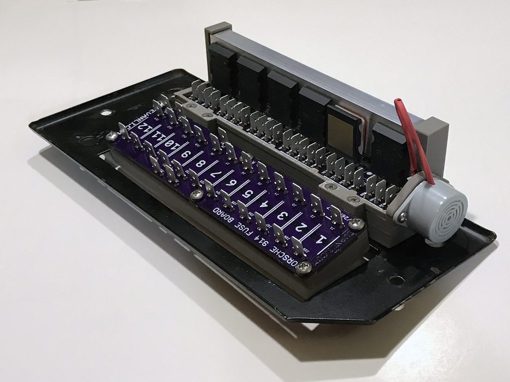
I hope this version will be the one to makes it to production. Feedback, improvements, and comments are appreciated. The first couple units are going to be stress tested over the next couple of weeks to validate the design.
Posted by: euro911 Aug 14 2017, 11:12 PM
Very nice, Evan. With the solid-state relays you've employed, will this cure the load issue when running LED turn signals?
Also, this unit is all that's needed to supplant the J-West or Engman fuse blocks and relay unit(s)?
If you're still looking for guinea pigs ... I'm your huckleberry 
Posted by: Evan0 Aug 14 2017, 11:33 PM
Very nice, Evan. With the solid-state relays you've employed, will this cure the load issue when running LED turn signals?
Also, this unit is all that's needed to supplant the J-West or Engman fuse blocks and relay unit(s)?
If you're still looking for guinea pigs ... I'm your huckleberry
It doesn't have the load issue with LEDs, but it does require that the turn signal indicator lamp be replaced with a LED bulb as well. It's a annoying limitation of the design. The integrated fuse and relay panel would be all you needed.
Posted by: McMark Aug 15 2017, 10:35 AM
That's pretty freakin' awesome.
Posted by: euro911 Aug 15 2017, 12:45 PM
With Jerry's LED lights, Timothy's LED gauges and Evan's relay panel, there's some real nifty stuff available these days 
Posted by: McMark Aug 15 2017, 01:44 PM
Thought of something...
While I love the wire color printed on the board, I thought some of the wire colors changed on different years. It may be better to simply label each connection with the original relay pin number (30, 85, 86, 87, 87a). If I were troubleshooting a car with that board installed and I wouldn't want to have to pull out and analyze the wiring diagram to translate wire colors to pin number and function.
On the fuse board, it would be prudent to add either a couple extra constant power connections and a couple switched power connections, OR add a couple extra fuses for add-ons.
Posted by: GregAmy Aug 15 2017, 02:32 PM

Posted by: mepstein Aug 15 2017, 02:34 PM
Thought of something...
On the fuse board, it would be prudent to add either a couple extra constant power connections and a couple switched power connections, OR add a couple extra fuses for add-ons.
 it would make engine conversions a lot easier to have the extra connections.
 Love what you are doing.
Posted by: JoeD Aug 15 2017, 02:39 PM
Yes please!
Posted by: 914_teener Aug 15 2017, 03:17 PM
I.m in after doing my latest "gremlin" project on my car.
Posted by: Evan0 Aug 15 2017, 03:54 PM
Thought of something...
While I love the wire color printed on the board, I thought some of the wire colors changed on different years. It may be better to simply label each connection with the original relay pin number (30, 85, 86, 87, 87a). If I were troubleshooting a car with that board installed and I wouldn't want to have to pull out and analyze the wiring diagram to translate wire colors to pin number and function.
On the fuse board, it would be prudent to add either a couple extra constant power connections and a couple switched power connections, OR add a couple extra fuses for add-ons.
It's not a big deal to add the relay pin number to the labels. But can someone confirm if the relay specific wiring connections changed color from year to year and if the relay wiring is significantly changed year to year?
Not a bad idea to add switched and straight battery power to the fuse panel, I'll add that to revision B.
Do you guys have opinions on how the fuses should be labeled? Should it indicate the amperage and a function symbol? What would be best to accommodate cars from different years?
Posted by: euro911 Aug 15 2017, 04:05 PM
... All of the above mentioned items:
Fuse position # ... 1 ~
Fuse rating for each position
Function symbol for each fuse position would be nice too
A couple extra fuse slots labeled 'AUX'
Posted by: Jeff Bowlsby Aug 15 2017, 10:05 PM
Yes different MY 914s have different fusepanel and relay circuitry. Fuse amperages and layouts changes too.
KISS. Just number the fuses 1-12 just like the factory schematics. someone else can figure out what goes where for the different years.
Posted by: Evan0 Aug 16 2017, 12:04 AM
Another question, how critical is the angle on the fuse panel in relation to the harness bundle? Would removing the tilt negatively affect strain relief on the harness? Optimizing the design for injection molding with that angle is proving to be a pain and removing that tilt would solve many issues. Thanks.
Posted by: Spoke Aug 16 2017, 06:48 AM
Beautiful design. Looks really well thought out. Lots of good feedback from the guys too.
One question on the placement of SSR U6 for the low beam: Why is it turned around WRT to the other SSRs? With it's positioning, its exposed pad is not against the heatsink. Was this done for isolation? What is the theta-JC from junction to the EP versus junction to top of case?
Posted by: Jeff Bowlsby Aug 16 2017, 08:32 AM
I amm pretty sure - not positive - that the slant is to enable a better viewing angle of the fuses where it is mounted. As long as the terminals are oriented normal to the back of fuse panel there is no unusual strain condition at each terminal
Wondering...what is intended for a fuse panel cover? The stock cover indicates the functions of each fuse.
Posted by: 914werke Aug 16 2017, 08:42 AM
Wow cant believe I missed this thread.
Extremely nice work and commend your willingness to accept & incorporate the feedback !!!
Put me on the list~
Posted by: 76-914 Aug 16 2017, 08:51 AM
Impressive!
Posted by: Vacca Rabite Aug 16 2017, 08:58 AM
Want want want want want.
Seriously. I want this.
Zach
Posted by: Evan0 Aug 16 2017, 10:33 AM
One question on the placement of SSR U6 for the low beam: Why is it turned around WRT to the other SSRs? With it's positioning, its exposed pad is not against the heatsink. Was this done for isolation? What is the theta-JC from junction to the EP versus junction to top of case?
I'm regretting the placement of U6 and it going to get flipped around for the next revision. I'll need to move a couple other components around to make that happen. I had it in that orientation originally to simplify routing. 7mm thick traces on both side are required to meet my current and temperature requirements, so routing was a bit of an issue. Thermal resistance junction to case is 0.3°C/W and junction to ambient is 33°C/W. The heatsink is approximately 28°C/W. I'm going to run a thermal test with a thermal camera with three of the relays carrying 12A, which should reflect worse case real world use. I'll incorporate anything learned from that test in the next revision.
Wondering...what is intended for a fuse panel cover? The stock cover indicates the functions of each fuse.
Thanks for answering my question. If its not critical to the connecting terminals, I think i will straighten it out to make injection molding much easier and cheaper. Is there a source for the stock cover? If reproductions are available, I would like to go with those to maintain some look of originality.
Posted by: JWest Aug 16 2017, 10:37 AM
"3. The new fuseblocks do not have the bussed together lugs that the factory fuseblocks do, so makeshift additional terminal busses are needed or the circuitry is altered to accommodate, making the factory wiring schematic useless for troubleshooting."
This statement is not true. Engman had a flaw in his process of doing it, from what I understand, but did have it. Maybe he sold some without it? Mine have always been bussed just like factory and it is the most difficult part of manufacturing these, since they have to be fully disassembled and modified internally.
But irrelevant if this makes it into production. I am all for a better design, as I am not willing to put in the time to design a fuse box from scratch and the connection positioning is not optimal for the stock harness to bend around to reach. I keep it going since there is nothing better on the market.
Let me know when this makes it to retail sale and I'll push customers to it (or resell on my site if that is of interest to you).
Posted by: 914_teener Aug 16 2017, 02:50 PM
One question on the placement of SSR U6 for the low beam: Why is it turned around WRT to the other SSRs? With it's positioning, its exposed pad is not against the heatsink. Was this done for isolation? What is the theta-JC from junction to the EP versus junction to top of case?
I'm regretting the placement of U6 and it going to get flipped around for the next revision. I'll need to move a couple other components around to make that happen. I had it in that orientation originally to simplify routing. 7mm thick traces on both side are required to meet my current and temperature requirements, so routing was a bit of an issue. Thermal resistance junction to case is 0.3°C/W and junction to ambient is 33°C/W. The heatsink is approximately 28°C/W. I'm going to run a thermal test with a thermal camera with three of the relays carrying 12A, which should reflect worse case real world use. I'll incorporate anything learned from that test in the next revision.
Wondering...what is intended for a fuse panel cover? The stock cover indicates the functions of each fuse.
Thanks for answering my question. If its not critical to the connecting terminals, I think i will straighten it out to make injection molding much easier and cheaper. Is there a source for the stock cover? If reproductions are available, I would like to go with those to maintain some look of originality.
Personally I think the stock cover is not practical. Why not a sticker or silk screen over a cover One has to pull the fuse anyway to check it. .I.m with Jeff...KISS.
Posted by: Spoke Aug 16 2017, 04:18 PM
I'm regretting the placement of U6 and it going to get flipped around for the next revision.
Very few products make it to production with Rev 1. I recently did a PCB for the people mover trains at Newark Airport where I reversed the coil leads for 6 relays.
 . Fixed it in Rev 2.
Posted by: Evan0 Aug 26 2017, 02:40 PM
Update 8/26/2017
Been on vacation for the last couple weeks so not much progress. I did get around to doing a thermal test of the relay board.
Here's a picture of the test setup. 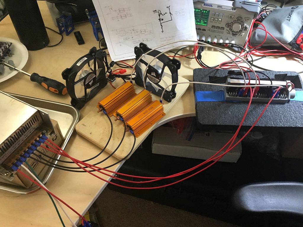
A 12V 600W power supply provides the juice to drive current through the solid state relays. Three 1Ω 200W resistors provide the load for the test. The fog, air fan, and low beam relays were chosen to as the test subjects since they are the high current draw items. The resistors actually measured about 1.2Ω so with 12V it should provide 10A through each of the relays. Left it running for about 20 minutes to reach steady state. 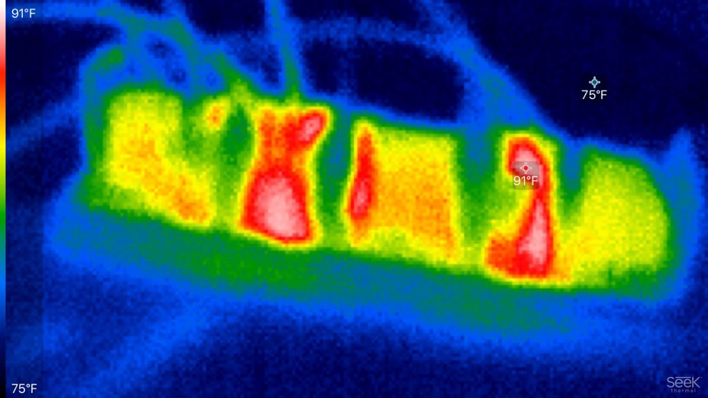
The max measured temperature was about 91°F, 15°F above ambient. Looks like the heatsink is doing its job correctly. The load resistors did get quite toasty during the test run. 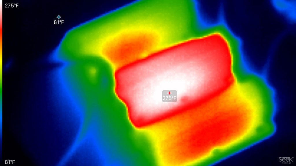
With 30A passing through the PCB and the relays, there doesn't seem to by any issues. With these results I'll get to work with Rev B and figuring out how to mass produce these at a reasonable cost.
Posted by: davehg Nov 14 2017, 05:49 PM
Any updates on this? I'm a few months away from tackling the electrical portions of my restoration and would love to commit to a fuse block solution.
Posted by: mb911 Nov 14 2017, 07:17 PM
This is a very cool project.. I would be interested.
Posted by: Larmo63 Nov 14 2017, 07:48 PM
I'm glad there are people in this world who are smart enough to know this stuff.
I have my own skill set, and I'm really good at Jeopardy, but thank you for making me feel like a complete nincompoop.
Posted by: mepstein Nov 14 2017, 08:04 PM
I'm glad there are people in this world who are smart enough to know this stuff.
I have my own skill set, and I'm really good at Jeopardy, but thank you for making me feel like a complete nincompoop.
I had a great feeling of accomplishment when I screwed the shift knob Zach had made for me, into the rennshifter lever. Righty tightly, lefty loosey.
Posted by: GermermanCarGuy Nov 14 2017, 08:08 PM
Can't believe I miss this one too.
Quick question. Will these work with Spoke's LED turn-signals?
If so, this would definitely be something I'd be interested in too.
Posted by: mobymutt Nov 14 2017, 08:26 PM
I can't say I totally followed everything that's been said on this thread, but it sounds like an awesome upgrade!
Would it be possible to add some extra connections for auxiliary items that weren't on the stock car? For example, my car has at least two extra connections (electric water pump and electric fuel pump, maybe more but I can't recall offhand), and they are just tied in via split spade connectors, which is horrible. Would love to have a proper spot on the fuse panel for them.
I'm thinking maybe 2 or 4 extra fused connections that people can use for whatever?
Does this even make sense? Keep in mind that I don't know anything about electronics...
Posted by: davehg Dec 16 2017, 11:18 PM
Bump to encourage this project again. Getting closer to wiring the car, and with no one currently offering replacement fuseblocks I may need to grab an old one - really want something modern.
Posted by: forrestkhaag Dec 17 2017, 11:32 AM
Very nice detail in the revisions along the way. I judge it to be an excellent upgrade and support the addition of multiple "unused" fuses in the offering. When will this setup be to market? I'm all in.
Attached image(s)
Posted by: Jett Dec 17 2017, 01:13 PM
Amazing and passionate work! I’m in for at least one, as long as Jeff B. is ok with me connecting his harness to it
...really great work!
Posted by: 914Toy Dec 17 2017, 01:24 PM
I am in on this one - nice work.
Posted by: GermermanCarGuy Dec 17 2017, 04:26 PM
Okay. Definitely in for one once released.
For the Subi crowd, 4 extra fused slots would be a great mod2. That would cover our electric fans, water pump, and fuel pump plus one.
Rob
Posted by: StratPlayer Dec 17 2017, 07:58 PM
Put me on the list please..
Posted by: mobymutt Nov 26 2018, 06:15 PM
Bumping an older thread. I still want this!
Powered by Invision Power Board (http://www.invisionboard.com)
© Invision Power Services (http://www.invisionpower.com)