Printable Version of Topic
Click here to view this topic in its original format
914World.com _ 914World Garage _ Tony's Subaru Conversion Thread
Posted by: TonyAKAVW May 19 2005, 11:10 AM
Well, I figured since there has been some pickup in momentum on this project that I would start a thread on my progress. Not to mention its a good way to share whatever ideas I pick up along the way.
The project started in January 2003 when I picked up the silver roller pictured below. Its a '74 and was pretty much stripped. It had a suspension and a few other parts but was missing a lot of major things like and engine, transmission, glass, hoods, gas tank, interior, wheels, etc. etc.
The story of my acquisition of this roller is in this thread:
http://www.914world.com/bbs2/index.php?act=ST&f=2&t=7991&hl=
After arriving at home:
http://www.914world.com/bbs2/index.php?act=ST&f=2&t=8963&hl=
This project got a bit of a slow start. I had to first part and chop up my first 914 and dispose of it. It was badly rusted and where itwasn't rusted it was bondo'd. This was going to be a replacement body for that car.
Then last summer I picked up the yellow '70 roller that is now my daily driver. Since then I've spent most of my 914 time fixing it up and getting it ready for WCC. Now that its in a pretty much stable state and WCC is over I can concentrate on this car.
The current plan is that it will get a Subaru 2.5L naturally aspirated engine in a conversion very similar to Scott Thacher's. The basic timeline is like this:
1. Fix up the body enough to make it roadworthy.
2. Put together the drivetrain (engine, adapter, transmission)
3. Install drivetrain and remaining parts
4. Install an exhaust system and wire up the engine, make it ready to drive
5. Install enough interior to drive it.
6. Drive it around a bit, fix whatever things don't work right
7. Flare the fenders (GT flares)
8. body and paint
9. Finish the interior
10.Performance mods - cams, etc.
I'm hoping that I get it at least roadworthy within a year, and the rest of the stuff within a year after that. Its possible I could get it done faster but we'll see. This is a big project.
Here's the car as it was when I brought it home:
Attached image(s)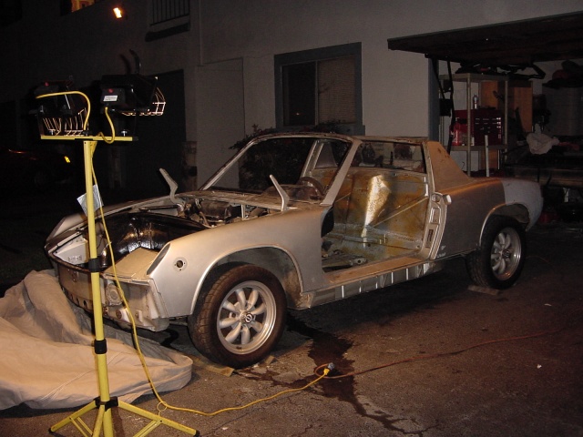
Posted by: TonyAKAVW May 19 2005, 11:12 AM
Here's a detail picture. This is the weather channel on the passenger side front fender. Something funny going on here.
Attached image(s)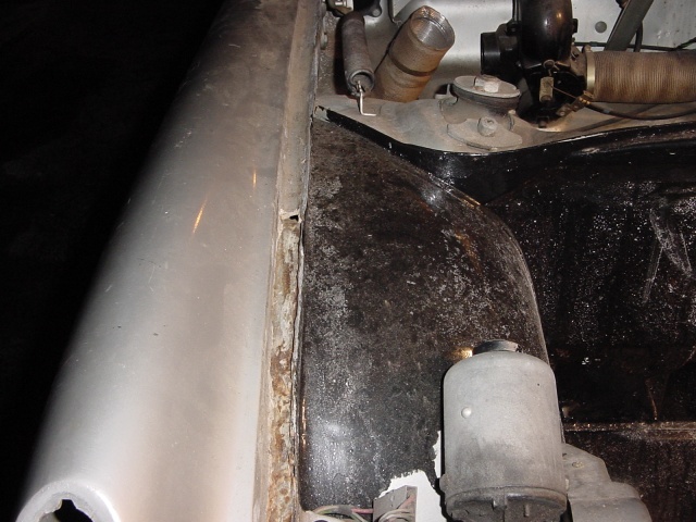
Posted by: TonyAKAVW May 19 2005, 11:13 AM
First job I decided to tackle was taking the interior down to bare metal. Work from the inside out.
Attached image(s)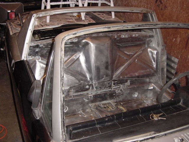
Posted by: TonyAKAVW May 19 2005, 11:14 AM
Some more ugliness on the front fender.
Attached image(s)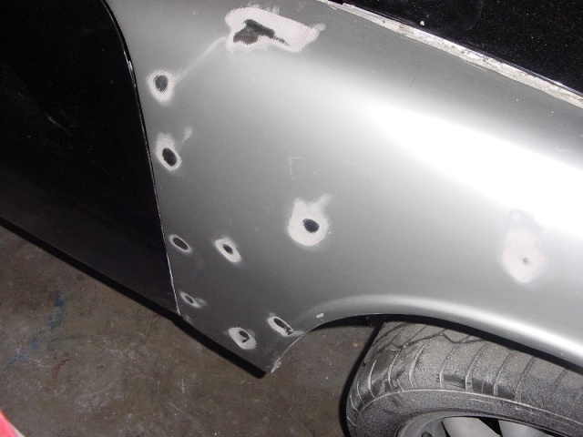
Posted by: TonyAKAVW May 19 2005, 11:15 AM
Well, the fender was junk, so I removed it.
Attached image(s)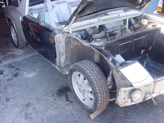
Posted by: TonyAKAVW May 19 2005, 11:23 AM
Heres the floor, stripped to metal.
Attached image(s)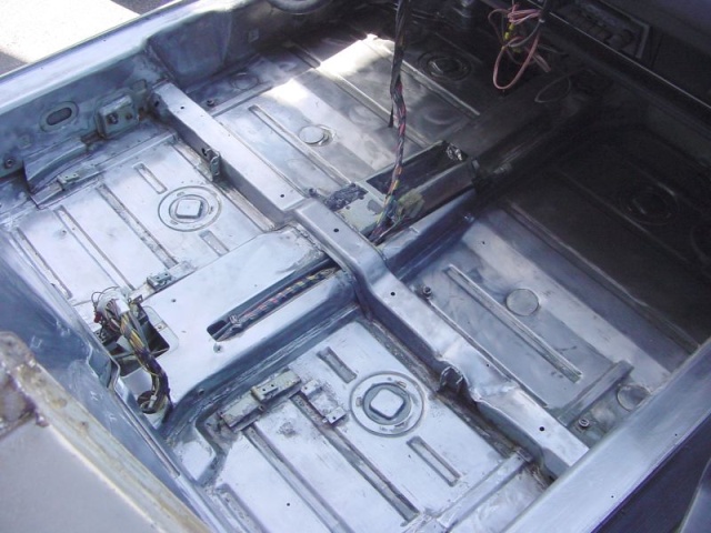
Posted by: TonyAKAVW May 19 2005, 11:24 AM
Another messed up fender. I have since found and prepared replacement fenders for both the front and rear damage.
Attached image(s)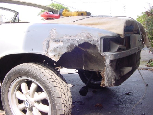
Posted by: TonyAKAVW May 19 2005, 11:27 AM
The whole interior got treated with metal etch and the POR-15.
Attached image(s)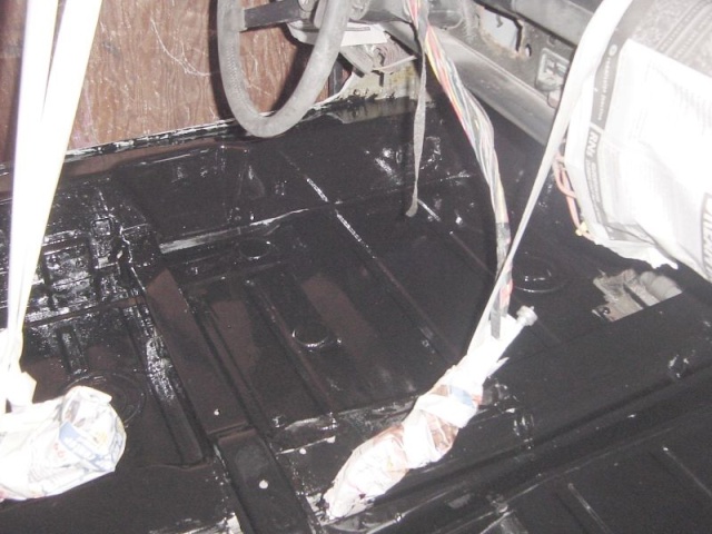
Posted by: TonyAKAVW May 19 2005, 11:31 AM
Here's the engine that is going into the car:
Attached image(s)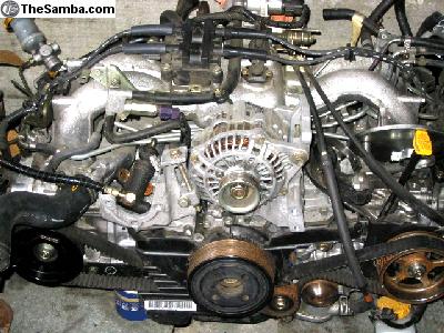
Posted by: Dr Evil May 19 2005, 11:33 AM
In the first pic your cord is lying in some fluid where the plug is 

The last pic is where I am heading right now. Nicely done.
POR-15 
Posted by: TonyAKAVW May 19 2005, 11:36 AM
The motor came with the ECU, wiring harness, and a bunch of other stuff. Its currently with Jeff up in Mountain View but will be coming down in June thanks to Jenny's kind offer to bring it down with her on a trip to Long Beach.
Its a 2001 2.5RS motor, puts out 165 HP stock and has 41,000 miles on it. Turns out that the previous owner of the engine had bought the engine from a wrecked 2.5RS. The really wierd part is that the wrecked 2.5RS belong to Jeff's roommate. So the engine started in a car in Jeff's garage, got wrecked, was sold to a guy in San Francisco, and then came back to its original garage. I wonder if this engine is cursed. Maybe its like the tape in the movie The Ring.
I'm working now on getting an engine adapter plate and flywheel to get the drivetrain put together. I have a good transmission that I bought from Glenn of D&G a while back.
-Tony
Posted by: Rotary'14 May 19 2005, 11:39 AM
Congratulations on getting off your ass Tony!! (I am having the similiar problems)

A slow start is better than a "no" start. You should get to work because it would be a shame to have all the metal (that you stripped) start to rust again.
How goes the drive train plans? While working on the body I'm sure your paying attention to the needs of your cooling system.
Post more pics soon so we can watch progress!
Good luck on your project/adventure 
Posted by: TonyAKAVW May 19 2005, 11:42 AM
| QUOTE |
| In the first pic your cord is lying in some fluid where the plug is The last pic is where I am heading right now. Nicely done. |
That fluid was runoff from a sprinkler from hours earlier. Not very deep.
Stripping the interior down to metal was a LOT of work. I live in an apartment and so I have to do things quietly. I did manage to use the angle grinder with the wire wheel for a while, but finishign it off required a ton of work with chisles and so forth to get seam sealer out of the corners.
I'm pretty happy with the results though. I should probably rough it up and put a second coat on.
-Tony
Posted by: AndyC May 19 2005, 02:58 PM
Another scooby doo conversion, I have a friend who works for a company called Prodrive building Subaru WRC rally cars here in the UK so if you need some very expensive performace parts let me know. He is still trying to convince me to scooby mine, his last argument was 500bhp from a £500 engine 
Posted by: Scott Carlberg May 19 2005, 03:32 PM
| QUOTE (AndyC @ May 19 2005, 12:58 PM) |
| Another scooby doo conversion, I have a friend who works for a company called Prodrive building Subaru WRC rally cars here in the UK so if you need some very expensive performace parts let me know. He is still trying to convince me to scooby mine, his last argument was 500bhp from a £500 engine |
Prodrive, that's cool!
Same company that ran the Ferrari 550's & now the Aston Martin's in the ALMS/IMSA series.
Posted by: Aaron Cox May 19 2005, 03:54 PM
nice ring ™ reference
very cool. you are going to have a beasty mobile.... whats a 2.5rs motor spin to safely?
and...as always. get'r done!
Posted by: lapuwali May 19 2005, 03:56 PM
| QUOTE (Scott Carlberg @ May 19 2005, 01:32 PM) | ||
Prodrive, that's cool! Same company that ran the Ferrari 550's & now the Aston Martin's in the ALMS/IMSA series. |
Believe me, the WRC stuff is WAY cooler...
Prodrive doesn't just build ANY Soob WRC cars, they build the FACTORY WRC cars, and have won several World Championships. One of their drivers is running second in points right now.
If any parts could be obtained from that place, they'd be the best available. I'd love to know the recipes they used to build engines even 5 years ago. 300hp/500ft lbs 2.0 turbos with wide, smooth powerbands, which could easily make 500hp if you removed the required intake restrictor. You'd be able to break 901s at a dizzying pace.

Posted by: scott thacher May 19 2005, 04:00 PM
one of the biggest pluses of this conversion is the radiator and cooling are in the engine bay so no cutting
tony the car look good and is you want more hp go to cobb tuning, he has the suby motors down pat
edit for aaron the suby motors have a hard redline of 7 k and the tachs ahave a redline of 6500. i have hit the rev limiter a few times, one of those was at willow i hit first at 45 or so mph opps
Posted by: scott thacher May 19 2005, 04:06 PM
arron here is the 2.5 ltier torque curve, the thing that amazes me is they have the stock intake and exhaust over 100 % ve
Attached image(s)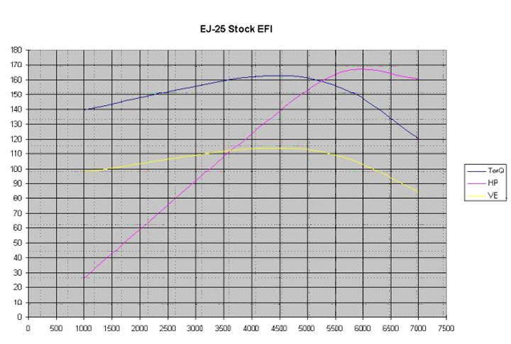
Posted by: TonyAKAVW May 19 2005, 04:06 PM
All that horsepower sound fantastic but it comes at the cost of one of the key things I like about this conversion and that is to have the radiator in the engine bay. I like having two trunks, and using the front for a radiator kinda sucks. With 500 HP I seriously doubt you could get enough cooling from an engine bay radiator. It would end up being more like a V8 conversion in many ways.
As far as rpms, I've seen people saying 8000, but more commonly I've seen 6500. I'll probably keep it conservative for a while.
Scott: I agree Cobb is the way to go. for my engine (SOHC) the cams are $500 and give you something like 15-19 HP. There's a guy on the NASIOC board who has a 225 HP naturally aspirated 2.5 engine. He's using the Cobb cams, and has bumped up the compression ratio. It seems like getting above 200 HP is going to be very doable. Oh, btw he's going to put this engine in a 914. Although he said he's going to ditch the EFI and use webers. I don't really understand why, but he claims it will give him even more horsepower. I've never heard that carbs give you more HP than a proper EFI system, but whatever.
-Tony
Posted by: Aaron Cox May 19 2005, 04:09 PM
dude. taht looks like serious fun.
that torque curve looks fantastic 
Posted by: TonyAKAVW May 19 2005, 04:09 PM
Here's a thread about the engine I just mentioned.
http://forums.nasioc.com/forums/showthread.php?t=595740&highlight=dyno+results
Posted by: lapuwali May 19 2005, 04:28 PM
It's possible the stock intake plenum and throttle body are too restrictive for a high power engine. They're made for 160ish HP, not 200+. If you used IDF-style throttle bodies and EFI, you'd see the same gains, but you'd also retain the advantages of EFI. You'd also have to fab up a linkage (unless someone makes one, or you could adapt a VW Weber linkage, and hassle with synchronizing multiple throttles.
Certainly, at some point, the stock intake will become the limiting factor. 200hp from a 2.5 is quite decent, and I'd be pretty happy with that from a street engine. As you say, you're also eventually going to hit the limits of the Thacher Cooling System™. I'd concentrate on removing weight from the car after the 200hp mark was reached.
Posted by: scott thacher May 19 2005, 04:42 PM
nope the stock fi is good to 220 hp with cobb tuning cams and heads. it just cost 2500 for that
Posted by: Aaron Cox May 19 2005, 04:47 PM
tony, how long till we see turbo(s) installed?
been for a wild ride in a 500hp turbo scooby sandrail.....
very cool indeed.
i assume your still laying power to the pavement via a 901?
or do you have plans to beef that up too? (lsd etc)
Posted by: TonyAKAVW May 19 2005, 05:01 PM
Well, for now I just want to get the thing running. That is definitely a big enough task. Turbos are not out of the question, but I probably will keep it naturally aspirated. Now if someday I run into a pile of money I would definitely be willing to put in an STI engine and crank that up to 500 HP.
The 901 will be used as is, or until something breaks. I'm trying to do this project cheaply (I'm a 914 owner of course) so putting in an LSD or high performance axles, or bigger CVs etc., is way over the budget. I'm basically trying to put in the engine and do as little other modifications as possible. I'm sure that after I've got the car running I'll find things I want to improve, but for now theres nothing extravagant in the plans except maybe for the fender flares.
-Tony
Posted by: TonyAKAVW May 20 2005, 01:32 AM
Here's the new front fender held in place with vice grips. When I got the fender it was essentially a quarter of a 914. It was a real chore to first cut off 90% of the excess metal and then drill out every single spot weld. Bondo helped out a lot by letting me use his brand new plasma cutter. I think that is perhaps one of the coolest tools around. Just the thought of vaporizing steel with electricity!
You can catch a glimpse of the new rear fender section in the front trunk.
Attached image(s)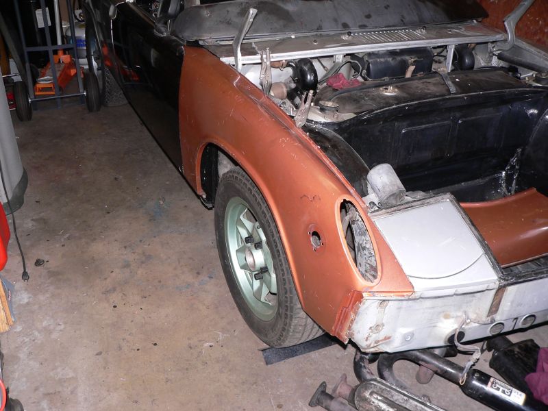
Posted by: AndyC May 20 2005, 02:16 AM
| QUOTE (lapuwali @ May 19 2005, 09:56 PM) | ||||
Believe me, the WRC stuff is WAY cooler... Prodrive doesn't just build ANY Soob WRC cars, they build the FACTORY WRC cars, and have won several World Championships. One of their drivers is running second in points right now. If any parts could be obtained from that place, they'd be the best available. I'd love to know the recipes they used to build engines even 5 years ago. 300hp/500ft lbs 2.0 turbos with wide, smooth powerbands, which could easily make 500hp if you removed the required intake restrictor. You'd be able to break 901s at a dizzying pace. |
Sorry for the Hijack
I am going for a look around their workshops when they all get back from Cyprus so I will take some recon photos for you all if they let me. As for parts check out their website www.prodrive.com and see if anything tickles your fancy, I am pretty sure he will arrange a discounted rate
Posted by: Hydra May 20 2005, 03:56 AM
Hey tony,
good to see you started working on your conversion.
As for the tranny setup, why don't you use a subaru 5 sp. manual tranny?
pros:
-it's a lot cheaper than a 901 (around 150$ for one in good condition
-it will allow you to have the engine placed about 5 inches more to the back, giving you more space for your radiator setup.
-and most importantly, you won't need the kennedy adapter kit (much less $$$)
cons:
-you will need to fabricate your own mounts for it.
-adapt a cable gear shift linkage
-adapt axles (but that is easy if you consider doing frankenaxle out of the subaru axles on the tranny end, and the 914 axles on the wheel hub end) 
my 0.02$
Best of luck
btw: i'm working on my eg33 conversion right now, and trying to figure out a way to mount the radiator in the optimal position for cooling, and it is such a major PITA.
oh and scott, i could really need those scoop pics...
Posted by: d914 May 20 2005, 07:28 AM
other issue would be you would need to find an older fwd tranny.all the newer ones are set up for awd......working on that solution right now..
Posted by: TonyAKAVW May 21 2005, 09:13 PM
Spent a few hours today cleaning out the unnecessary metal from the engine bay. The mtal I took out is the metal that surrounds the type 4 engine tin. Its unnecessary for a water cooled engine, so to make more space in the engine bay I got rid of it. I may also remove the stock engine mounts but for now I see no good reason to remove them other than aesthetics.
I have a bit of welding to do on the hell hole side of the car, but its not going to be too bad.
Attached image(s)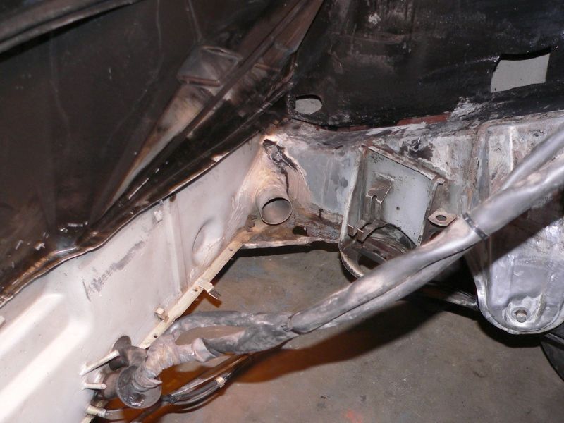
Posted by: TonyAKAVW May 21 2005, 09:14 PM
ll
Attached image(s)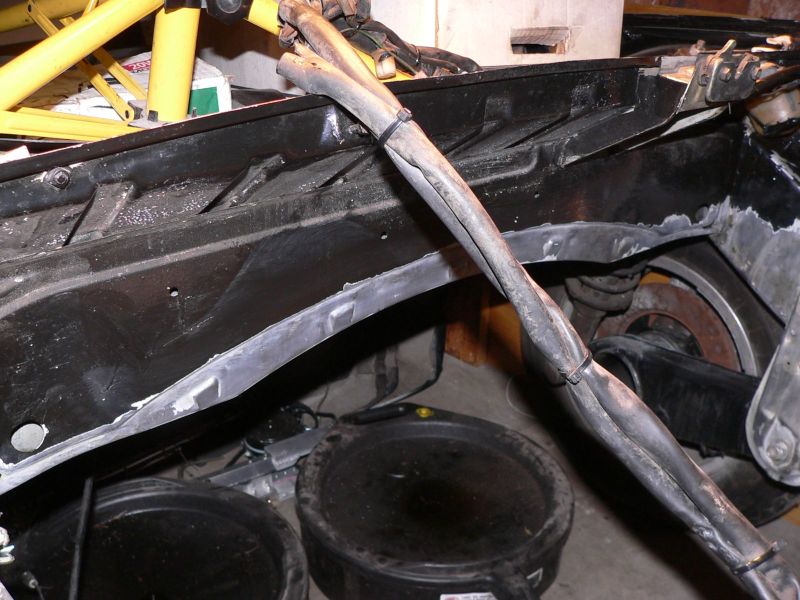
Posted by: TonyAKAVW May 21 2005, 09:14 PM
Some of the metal coming out from the firewall is still there. It comes out about an inch or less along most of the firewall. Getting rid of it alltogether is a bad idea, because the two halves of the fireawll joing together. If I need to remove more later I'll do so, but I suspect I'll be fine.
Attached image(s)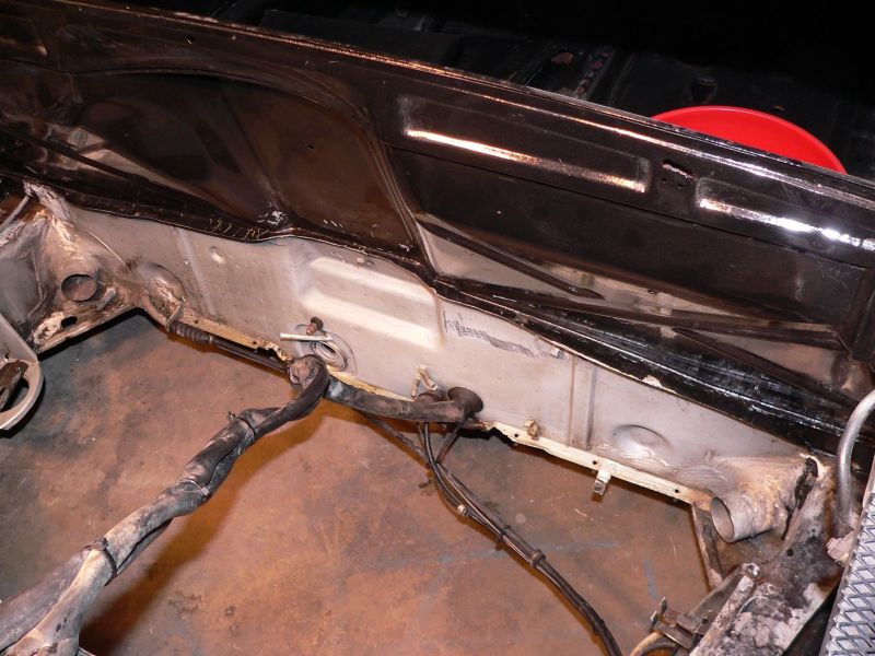
Posted by: TonyAKAVW May 21 2005, 09:15 PM
Next step is to paint over the bare metal with POR-15. I gave it a good treatment with a phosphoric acid rust converter, washed it off and dried it.
Attached image(s)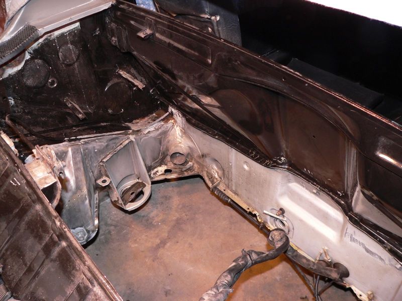
Posted by: 9144guy May 21 2005, 09:32 PM
is't that the engine off of ebay? i watched this motor looked cool, was the wiring harness extra? , i wonder how fast the car will fly, isnt it a turbo?
Posted by: redshift May 21 2005, 09:33 PM
Dood, your metal cleanup work is beautiful, way clean.
nice!
M
Posted by: TonyAKAVW May 21 2005, 09:39 PM
| QUOTE |
| Dood, your metal cleanup work is beautiful, way clean. |
Thanks!
I used a combination of cutoff wheels, grinding wheels, and a wire brush wheel.
| QUOTE |
| is't that the engine off of ebay? i watched this motor looked cool, was the wiring harness extra? , i wonder how fast the car will fly, isnt it a turbo? |
Nope, this engine was advertised on Craigslist in San Francisco and The Samba as well. $900 for the engine, harness, ECU, bunch of other crap. Not a bad deal. Its a naturally aspirated engine. I decided against the turbos due to their torque curves and complexities.
-Tony
Posted by: scott thacher May 21 2005, 09:43 PM
9144guy, i will tell ya the suby 2.5 moves out quite well.
at the wcc tony was talking with me about going turbo, it would be faster but the cooling might not work with the radiator in the engine bay. after tony got a ride in my car he decided that thou the turbo would be nice the car is plenty fast enough with out it.
tony as for the engine bay clean up what you did is perfect, the engine will fit very well. before you go any further i would recommend getting the wiring harness, fuel, and brake lines secured or set up to be. the reason i say this is the next thing you will have to work on after por 15 will be motor mounts and radiator frame. as a matter of fact you might want to start on the mount now so when you por the engine bay you can por the new mwtal as well.
edit: tony you could remove the stock motor mounts but they are really really well attached line 50 spot welds per mount
one thing i can say is i am jealous of tony, he does not need to guess as much as i did 
Posted by: 9144guy May 21 2005, 09:44 PM
kick a$$
Posted by: 9144guy May 21 2005, 09:52 PM
i wanted to turbo my 1.8 liter. we had a 930 slant nose(steel) that came into the shop with twin turbo garretts/w built in wasegates and water cooled intercoolers, my boss bought it, and went back with stock parts,turbo, and a intercooler,also had halltec injection box,,i have acess to the parts but, i decided to go with stock inj. so my wife could have fun with it instead of me wondering when it could pop. maybe some day with another engine
Posted by: TonyAKAVW May 21 2005, 10:22 PM
I have begun thinking about how to do the radiator frame. I am at this point going through many different ideas, but really until I get a radiator and see how it fits in, its all just ideas. One idea I still have is to make a frame for the radiator that attaches to the motor mount. In the end this will probably weigh a lot, be difficult to fabricate, especially around the interface to the firewall. I'll probably POR-15 the engine bay as much as possible now, then after the frame is done re-do those sections. There's a lot of bare metal...
My next project after the POR-15 will be figuring out what to do about wiring. I will be going a bit crazy with the wiring making it over-connectorized. I will probably have bulkhead conncetors at the firewall rather than having a wiring harness come through, as well as at the trunk wall. I'm going to give myself plenty of extra wiring so that I can add things in the future that I have not yet anticipated. I also want built-in engine bay lights so that its easier to work in there. When the engine lid opens, the lights will come on. Should make it easier to debug when I'm on the side of the road in the middle of nowhere.
-Tony
Posted by: scott thacher May 21 2005, 10:29 PM
here is a cheap and easy way to get engine bay light... get one of the ricer light kits and install it on the firewall with a small switch that is a nc contact that gets released when the engine lid is up. this would cost about 20 bucks or so to do.
as for a bulk head connector, if you do that make sure it is not behind the radiator, for access reasons. also a good source for a connector is an early suby firewall connector they are like 26 pins and the pins are available new
edit: i would still do the radiator mounting now, so you dont have to move it later when you see it is in they way
Posted by: redshift May 22 2005, 12:40 AM
| QUOTE (scott thacher @ May 21 2005, 11:43 PM) |
| at the wcc tony was talking with me about going turbo, it would be faster but the cooling might not work with the radiator in the engine bay. after tony got a ride in my car he decided that thou the turbo would be nice the car is plenty fast enough with out it. |
I was thinking about cooling today, the answer to all your cooling problems... ENGINE TIN.
If you could get tin back around there, you get alot more cooling, without a pooper scooper, I am pretty sure..
Even at lowish speeds, there is a massive disparity in air pressure, above and below. The ass of a teener is a kite.
M
Posted by: Michael J May 22 2005, 11:35 AM
Tony,
Keep the updates coming. I think the idea of a basically stock Suby engine will have a lot of appeal. If I could double the HP from my 1.7 and not take on a bunch of maintenance headaches I would sure give it some thought. I just want a REALLY fun driver. Don't race.
And I commend you for taking this project on in an apt. garage. I can barely turn around in my garage and I don't have to worry about pissing off the neighbors.
Good luck.
Posted by: Dr Evil May 22 2005, 12:05 PM
Michael J,
Check out Scott Thatcher's suby conversion for a done, stock, fun to drive one. He pioneered the mounting of the radiator in the engine bay infront of the engine, and proofed it buy driving it from MD to CA for the WCC05. If I had time (oh ya, and money) I would do oneof these for sure. Tony is just taking it a step further
Posted by: TonyAKAVW May 31 2005, 11:29 AM
Just a teaser. I got the engine home last night. Hopefully I'll have some pictures to post tonight.
I stopped by Jeff's place at about noon yesterday and we picked up the engine and put it into the trunk of the camry. It took a little work but it fit eventually. I had to take off the alternator, the coil pack, and the throttle body. It leaked some fluids into the trunk and scraped up the paint a bit, but it managed to survive about 350 miles.
I'm going to try and recruit some coworkers to help me lift out the engine tonight.
Pictures at 11.
-Tony
Posted by: TonyAKAVW Jun 1 2005, 01:17 AM
In order to get the engine out of the car's trunk easily I removed the alternator, brackets, and the intake manifold/injector runners/throttlebody assembly aka "baby alien."
Its stunning how much the EJ25 looks like a type 4 engine, albeit 30 years more modern.
-Tony
Attached image(s)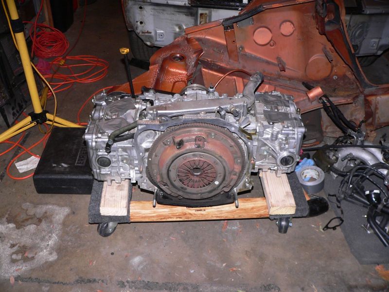
Posted by: TonyAKAVW Jun 1 2005, 01:18 AM
Baby Alien or a Four legged spider??
Attached image(s)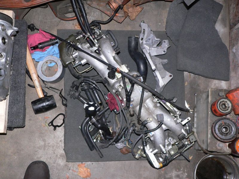
Posted by: TonyAKAVW Jun 1 2005, 01:18 AM
Bright blue powder coated rice. That must be good for like 50 HP.
Attached image(s)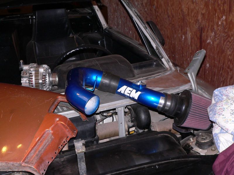
Posted by: TonyAKAVW Jun 1 2005, 01:18 AM
Needs a new timing belt cover. Probably a good opportunity to put on a new timing belt.
Attached image(s)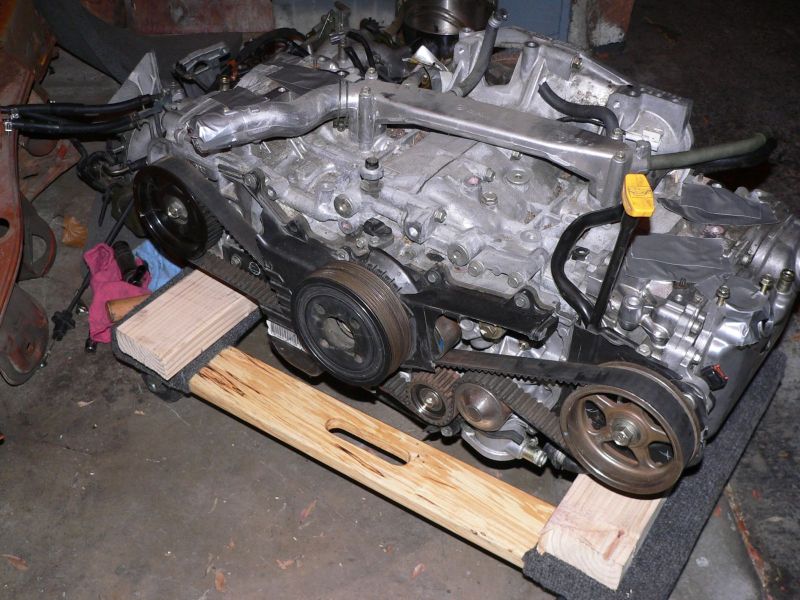
Posted by: TonyAKAVW Jun 1 2005, 01:19 AM
The Business End.
Attached image(s)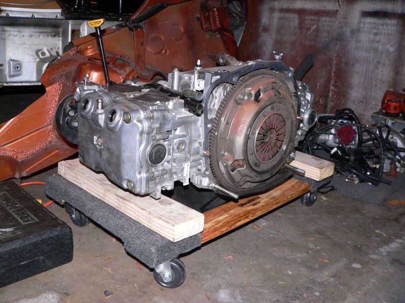
Posted by: TonyAKAVW Jun 1 2005, 05:55 PM
Intake port. Having only ever taken apart a type 4 engine it was interesting to see how the port is split into two and how the injector has two outlets at a corresponding angle as well.
-Tony
Attached image(s)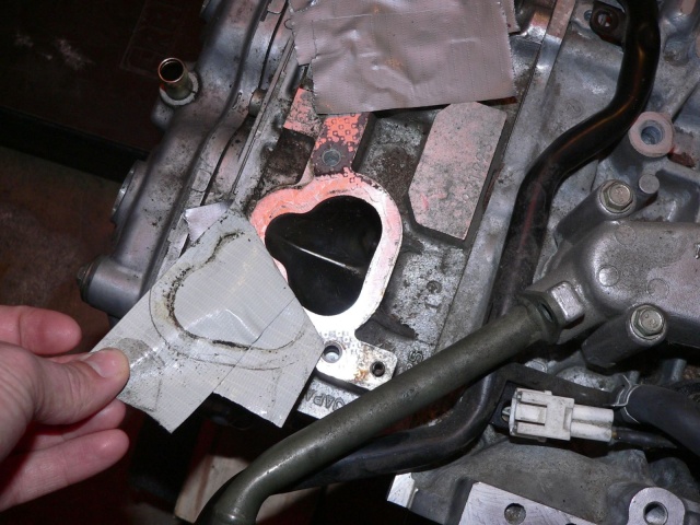
Posted by: 14Maschine Jun 1 2005, 06:55 PM
Awesome pictures man! Keep em comin!
Posted by: TonyAKAVW Jun 2 2005, 02:37 AM
I began the task of undoing the wiring harness tonight. It appears there are basically three sections to it. One that appears to be mostly within the engine bay, one for the dash area and another that I haven't yet figured out. The person who pulled the harness out was good enough to label a bunch of the conectors with what they went to. This was helpful in determining which harness does what (in general). I'm going to have to find a schematic somewhere, but this seems doable. A few conenctors will need replacing and a few wires will need splicing due to a small amount of damage during the acident that killed the car.
Its a bit premature to be doing this, but it looks like its going to be a fairly time consuming task. I believe one of the important things to do is come up with a new schematic for the electrical system of my car, as it appears it will be quite different than stock.
-Tony
Attached image(s)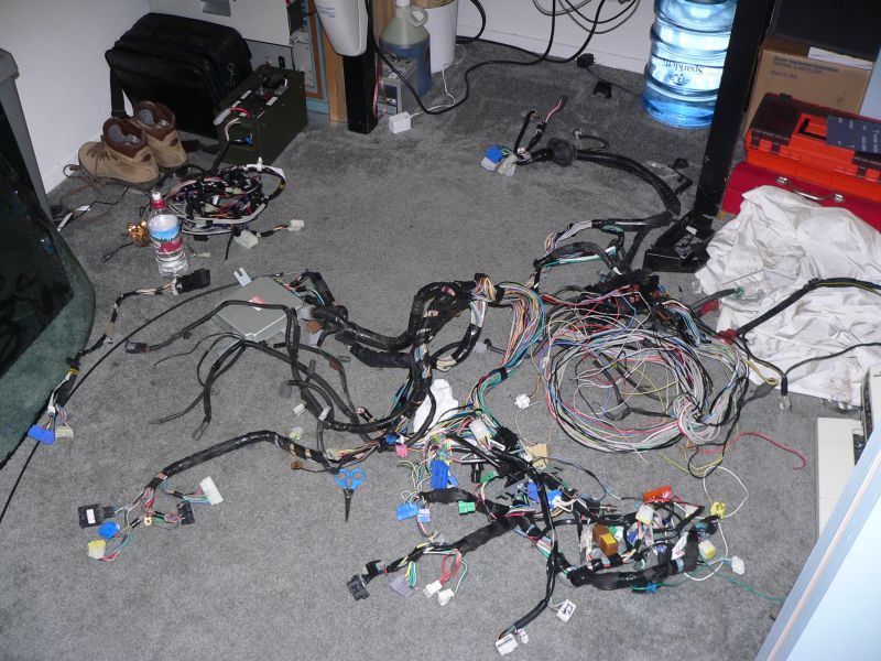
Posted by: jkeyzer Jun 2 2005, 05:39 AM
Hey tony, don't forget the timing belt is partly shredded. You definitely want to replace that before you put the engine in the car.
Posted by: Hydra Jun 2 2005, 06:27 AM
I've just noticed something strange: why does the engine have one plastic timing and the other one metal? iirc the early ej25's had dohc with plastic timing gears, but don't know much about the late sohc...
Posted by: turbo914v8 Jun 2 2005, 10:48 AM
Just a little something for youre informaiton, might give you a few ideas. Keep up the great work.
Regards,
Turbo Paul.


Posted by: maf914 Jun 2 2005, 10:59 AM
Interesting mount. Will you be able to get the shift rod through there? 
Posted by: Mueller Jun 2 2005, 11:01 AM
cannot use stock shifter linkage with TonyC's design...
The car pictured above is now going to use a single turbo with a WRX header I believe, so the front bar might be able to be modified to make room for the shift linkage....
a slight miscommunication between Jon and Tony...opps
Posted by: turbo914v8 Jun 2 2005, 11:06 AM
Glad to see that someone has information on this converstion as I dont. I just came across the pic's and thought you might be able to make use of them.
Regards,
Turbo Paul.
Posted by: Mueller Jun 2 2005, 11:10 AM
| QUOTE (turbo914v8 @ Jun 2 2005, 10:06 AM) |
| Glad to see that someone has information on this converstion as I dont. I just came across the pic's and thought you might be able to make use of them. Regards, Turbo Paul. |
I'm freinds with both Tony and Jon (not sure if they'll admit to it in public, hahahaha)
Posted by: TonyAKAVW Jun 2 2005, 11:13 AM
That engine support is nice looking, but there is a definite disadvantage to the design. Fiid has details on why the design is suboptimal here: http://www.914world.com/bbs2/index.php?act=ST&f=2&t=7882&hl=subaru%20turbo&st=140
I will be going with a bar more like Scott's which is basically a large U-shaped piece of square tubing that cradles the engine mounts and the arms stick up and bolt to the body near the shock/spring mount.
-Tony
Posted by: turbo914v8 Jun 2 2005, 11:17 AM
Mueller you have a PM
Regards,
Turbo Paul
Posted by: scott thacher Jun 2 2005, 12:22 PM
do not use the mount that goes off of the stock body mounts, i know of somebody who did this and it broke the bolt to the body mount as soon as it had the engine on it
you have to support the rear of the engine either with a mount like my mine or fiids
Posted by: TonyAKAVW Jun 2 2005, 06:41 PM
For anyone else out there who is doing a conversion I found a very valuable website.
http://www.ravensblade-impreza.com/
There's a ton of information there on the Impreza, including pinouts with desriptions for various model year ECUs, wiring diagrams, etc. Essentially all you need is the ECU pinout. From there you could make a harness from scratch if youw wanted to! I'm still planning on modifying the one I have, but this at least tells me which wires to keep and which ones to throw out.
-Tony
Posted by: plymouth37 Jun 22 2005, 10:34 AM
check this kit out. http://www.renegadehybrids.com/turbo914/914subaru.html
Posted by: TonyAKAVW Jun 22 2005, 12:20 PM
This thread is not dead... I have been working a lot on the wiring harness as well as ordering parts for the engine, and doing some conceptual drawings for the radiator bracket/shroud.
This design is very similar to Scott's radiator shroud/mount but is made entirely from aluminum and bolts on to the car rather than being a weld-in part. It is way more complex and has a lot more parts, and in the end will take about 30 times as long to build. Scott's method is simple and works great, mine is way over engineered, meaning it probably won't work 
Here's the first drawing giving an idea of what the thing looks like.
Attached image(s)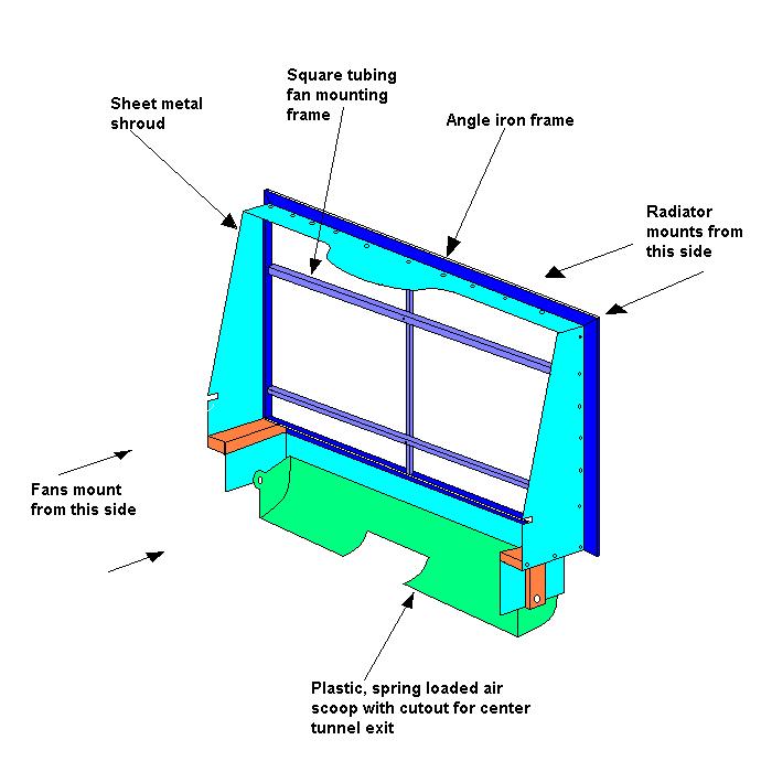
Posted by: TonyAKAVW Jun 22 2005, 12:20 PM
Another drawing to show conceptually how it fits into the engine bay.
Attached image(s)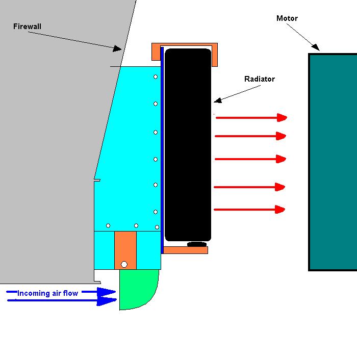
Posted by: TonyAKAVW Jun 22 2005, 12:22 PM
Here's some detail of the orange colored bars at the bottom of the shroud. These will be machined form a rectangular bar of aluminum.
Attached image(s)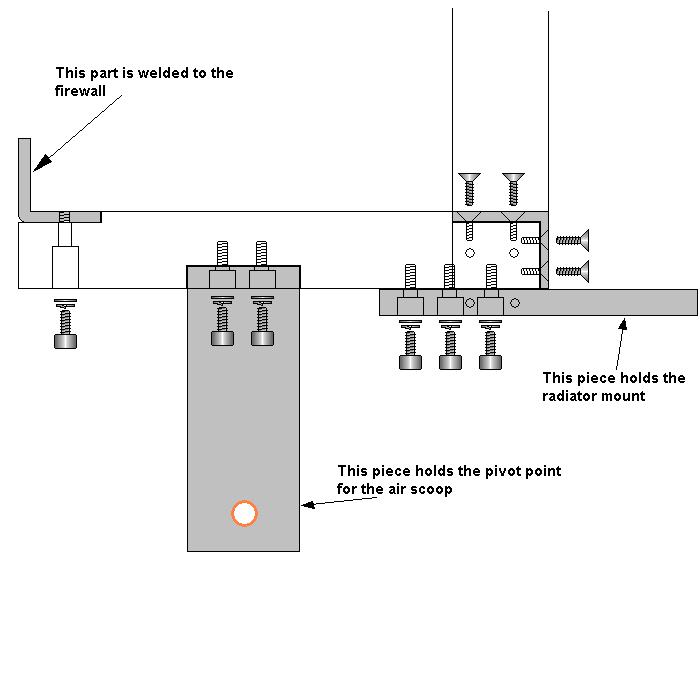
Posted by: TonyAKAVW Jun 22 2005, 12:23 PM
Here's the drawing from above with the addition of the plastic air scoop
Attached image(s)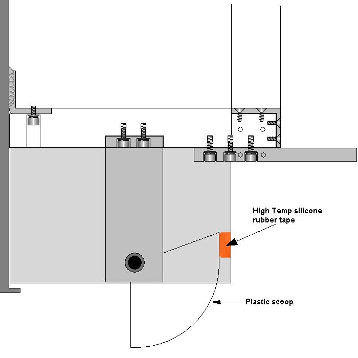
Posted by: TonyAKAVW Jun 22 2005, 12:24 PM
Some hardware detail of how the scoop is mounted...
Attached image(s)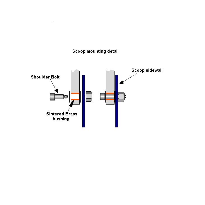
Posted by: Mueller Jun 22 2005, 12:27 PM
spring loaded so that if you hit something it rotates up to help minimize damage??
Posted by: TonyAKAVW Jun 22 2005, 12:31 PM
I have a few more drawings on paper that I did by hand, especially for the mounting of the top of the frame. Basically on each side, on the inside corner of the frame will sit a block of aluminum that will both hold the frame together and have an angled hole through which a bolt will pass, coming through the firewall. There's a standoff that will sit between the firewall and the block.
Another detail. The aluminum sheet metal shrouding will have a rubber gasket around its edge where it meets the firewall. This will be made from either a sliced piece of tubing or some standard material for the purpose.
The only welding for this is two small angle brackets on the vertical section of the firewall. These secure the bottom of the frame to the firewall, and welding is necessary because that section of the firewall is not accesible from inside since its double-walled. If you wanted to hack up the inner lower firewall you could get away without welding. It would probably just be a couple small holes.
One detail I have not yet worked out is the clamp that holds the top of the radiator. Probably won't be too tricky, but I need to wait until I have an actual radiator before doing that.
So anyone around the LA area have a milling machine I could come and use for a good part of a da?
-Tony
Posted by: phantom914 Jun 22 2005, 12:33 PM
| QUOTE (TonyAKAVW @ Jun 22 2005, 10:31 AM) |
| ..So anyone around the LA area have a milling machine I could come and use for a good part of a da? -Tony |
No.

Posted by: TonyAKAVW Jun 22 2005, 12:33 PM
| QUOTE |
| spring loaded so that if you hit something it rotates up to help minimize damage?? |
Exactly. It will be such that it can rotate up all the way so that it is flush to the floorpan. I was thinking that a spring _might_ not be necessary if the scooop is heavy enough to stay put at high speed, AND that the bearing point be smooth enough.
-Tony
Posted by: phantom914 Jun 22 2005, 12:38 PM
| QUOTE (TonyAKAVW @ Jun 22 2005, 10:33 AM) | ||
Exactly. It will be such that it can rotate up all the way so that it is flush to the floorpan. I was thinking that a spring _might_ not be necessary if the scooop is heavy enough to stay put at high speed, AND that the bearing point be smooth enough. -Tony |
Heavy means inertia which means it won't move easily when struck. I imagine it would slam pretty hard when it reaches the end of its travel also. I thought maybe using something flimsy and with flimsy mounting points so it would tear off if hit hard without damaging anything else.
Andrew
Posted by: scott thacher Jun 22 2005, 12:43 PM
tony that is basicly what i had designed, but here are 2 things for you to consider. one get rid of the fan mount and use the plastic thru core supports, you want the fans as close as you can get them to the radiator ie touching it. also the top of the radiator frame will be touching the firewall so your shrouding will be smaller.
if you want a complete fan set up that should fit perfectly but is not cheap go with http://www.prostreetonline.com/buy/fal_flexalite_fan_kits/fal-365/. from what i saw before it is almost a perfect fit on the suby radiator and it offers very good coverage so you get good flow.
Posted by: scott thacher Jun 22 2005, 12:47 PM
for heat i just found this it looks like is would fit up under the dash if you remove the stock fresh air stuff
http://www.prostreetonline.com/buy/fal_flexalite_heaters/
Posted by: TonyAKAVW Jun 22 2005, 12:51 PM
I didn't know that there were fans that mounted to the radiator itself. That definitely seems like the way to go.
As far as the radiator touching the firewall, I have to see how all this fits in the engine bay. I'm sure there will be some adjusting of the design once I have things roughly in place. This is just a first cut at it, nothing is measured. I may end up pushing the mount back towards the engine slightly to get the clearance if I need it, but I'll see when the time comes.
Andrew: I agree. But I also want this thing to be sturdy enough that when I go over speed bumps it doesn't tear it off. I'd like to be able to go over speed bumps (slowly) and have the thing stay intact, move out of the way, and then move back when the bump is over. After time this will wear down the leading edge of the scoop, but maybe I can put a strip of some really hard metal on there, like tungsten or something!!! or not.
-Tony
Posted by: Dr Evil Jun 22 2005, 01:00 PM
Put rollers in the lip of the scoop to help preserve it as it is being deflected up. Why not?
You could also pad the end stops of the scoops travel so it doesnt destroy anhting when you run over the piece of tire in the middle of the road.
Verry nice so far
Posted by: redshift Jun 22 2005, 01:03 PM
I am not sure that thing needs a grappling hook... I mean a scoop.
M
Posted by: phantom914 Jun 22 2005, 01:08 PM
If you use fans that are powerful enough and alter the scoop a little, could you use your 914 as a streetsweeper for hire to help defray the costs of the conversion?
Andrew
Posted by: TonyAKAVW Jun 22 2005, 01:31 PM
| QUOTE |
| I am not sure that thing needs a grappling hook... I mean a scoop. |
Could be. I will drive it without a scoop first and see how it goes. If it ends up getting too hot at high speed I'll put it on. in stop and go traffic, where you'd expect it to heat up the worst, the scoop won't do anything. So we'll see... I'd rather not have it...
-Tony
Posted by: redshift Jun 22 2005, 02:07 PM
I don't know if it would try to stall the fans, I'd try to get air from above.. I'd have to do a little testing.. I know the car is a wing back there.
You could sweep streets, and ROCK at autox... 
M
Posted by: Travis Neff Jun 22 2005, 02:13 PM
I'll toss this thought out.. The 73+ cars had the air deflector flaps on the floorpan, why not use these, or make one that goes the full width of the radiator.
Posted by: plymouth37 Jun 22 2005, 06:04 PM
| QUOTE (phantom914 @ Jun 22 2005, 11:08 AM) |
| If you use fans that are powerful enough and alter the scoop a little, could you use your 914 as a streetsweeper for hire to help defray the costs of the conversion? Andrew |
lol dude you are my hero. my renegade radiator cools great and will probably not be mistaken for a "street sweeper". for $1000 why not just bolt in something that you know will work?

 (best smiley ever!)
Posted by: TonyAKAVW Jun 22 2005, 06:20 PM
| QUOTE |
| lol dude you are my hero. my renegade radiator cools great and will probably not be mistaken for a "street sweeper". for $1000 why not just bolt in something that you know will work? |
Wow, I've never been a hero. I guess there's a first time for everything.
I'll give you a multitude of reasons why I'm not going to go with the renegade radiator.
1. I don't want to use my front trunk for a radiator.
2. I don't want to use my front trunk for a radiator.
3. It's exceedingly boring. For $30,000 why not just go buy a WRX STI, because I know that will work. In terms of engineering problems that have been solved in this world, I'm sure this is not up there in the top 100000, but for me it is an interesting project to work on and think about. Buying an off the shelf finished product is not really something I'm interested in.
4. I think its a poor value. I'm sure that its of exceptional quality and all, and that it will enhance the reliability of my car, but I believe it is overpriced. Thats my opinion, valid or not.
5. I can put together a perfectly good cooling system for $300 and put the remaining $700 into things like suspension, etc.
6. A renegade cooling setup is far less likely to inspire jokes.
So thats why...
Posted by: Mueller Jun 22 2005, 07:08 PM
Tony,
I say ditch the frankenstien looking bolt-together framework and make something with composites 
Find a mill yet? no problem using mine if you don't mind the drive 
Posted by: TonyAKAVW Jun 22 2005, 07:28 PM
oooooooh composites.
You know, the thought had crossed my mind in the past and it gracefully went the way of "I don't have any idea how to do that, there's a lot to learn
And here you go pushing back towards composites! A carbon fiber radiator housing would be pretty sweet, and I wouldn't even have to use the firewall as part of the shrouding. I could make a mold from wood and styrofoam or STOP!!! Geez. I have to at some point take a stand and limit my technology creep or else I'm going to be into this for 3 years and not have anything on the road. Not that there's anything wrong with that of course
I think for now I'll stick to metal. Mostly because to learn how to do composites and get the equipment necessary would take a lot of time. And then I'd want that nice shiny finish of a vacuum cured part, so I wouldn't be happy with it anyway.
If you try to convince me to go composites, I'm going to try and convince you that you should abandon your Link ECU and go with something else.  Or I'll try and get you to join the dark side of the Subaru Swappers Syndicate.
-Tony
afterthought.... This is not a structural piece, would be a great way to learn composites..... hmmm. Somone please stop me.
Posted by: scott thacher Jun 22 2005, 07:29 PM
mike can i use your mill, i have a few things that i need/want to make
and tony just weld the frame together and bolt it in, much time saved and you dont need to worry as much about bolts loosening
Posted by: redshift Jun 22 2005, 07:37 PM
Make it out of mahogany.
M
Posted by: plymouth37 Jun 23 2005, 11:02 AM
I hope that your radiator works. it is a really cool (no pun intended) idea. and the whole sleeper aspect to the thing is pretty sweet. I have been talking to scott about his radiator and it seems to be working great for him. I would be a little wary of this set up on a turbo motor though, they run pretty hot.
Posted by: scott thacher Jun 23 2005, 12:35 PM
dana FYI his is a na 2.5 as well, although i think he will do some tuner stuff to it
Posted by: TonyAKAVW Jun 23 2005, 07:07 PM
Yup, its a 2.5 N/A. I'm sure that putting in a turbo would heat things up a lot more. It would still be interesting to see if the engine bay cooling would work with a higher HP motor. No one has tried it AFAIK, but maybe with some creative ducting it could be done.
I do plan on at some point, putting in Cobb cams, and custom exhaust, etc. For now though its going to remain pretty much stock. Until I get bugs worked out, etc.
-Tony
Posted by: plymouth37 Jun 24 2005, 10:19 AM
mine is a turbo and it is amazing how fast that tiny 2.0 heats up. I blew a fuse to my cooling fans and within about 2 seconds of sitting in traffic things got pretty warmish. now I know to actually pay attention to that volt thing and to use the right fuses.
Posted by: TonyAKAVW Jun 26 2005, 12:24 PM
I met a major milestone in the wiring department this weekend. I stripped down the Subaru harness to minimum and labeled and identified every wire going into the ECU. The result is amazing. The original Subaru harness is now down to probably 5% of what it started out as!
-Tony
Attached image(s)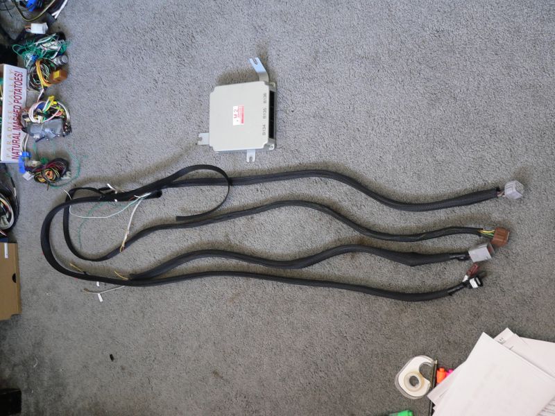
Posted by: scott thacher Jun 26 2005, 12:32 PM
that looks like you are mising a few plugs, but i cant see it all very well. dont tape it up too much you will probably have to open it up once to fix something.
all the plugs i can think of are :
brain
2 o2 plugs
3 for engine connection
fuel pump relay
main realy
ignitor
obd connector
purge and pressure switching solinoids ( 2 plugs )
connection to relay board
then loose wires are :
power
ground
speed sensor
temp sensor if you go stock
then you need wires from the alt
Posted by: Dr Evil Jun 26 2005, 12:44 PM
WTG! Very nice.
Posted by: TonyAKAVW Jun 26 2005, 12:46 PM
Yes a few things are missing form the picture... The engine harness itself is still on the engine and I believe (though I will have to double check) that the O2 sensors come off of that. The relay connections will be made inside "the box." The OBD connector as well. The ignitor is through the engine harness, as well as the purge valve. I think everything else is acoounted for....
-Tony
Heres the leftovers...
Edit: the black stuff around the wiring is just nylon expando sleeving. Its just there temporarily to keep the wires from going all over the place. I'm nto sure if I will eevn use it in the end, but it just slides off.
Attached image(s)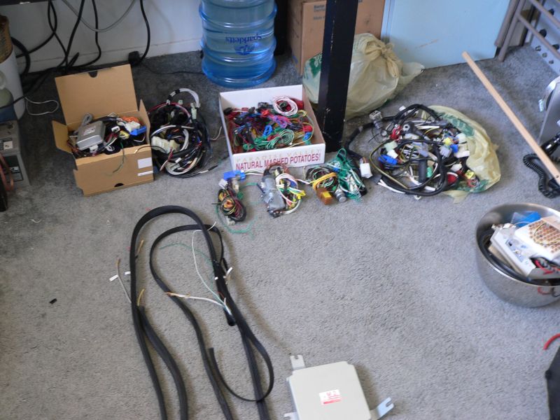
Posted by: TonyAKAVW Jun 26 2005, 12:54 PM
And now for the description of "the box." The "box" is going to be a weatherproof aluminum box that will tentatively go in the engine bay, though it could easily go in the passenger compartment if I find it gets too hot.
Anyway, the box will be the main wiring hub for the car. In essence it will replace the relay board and the 914 ECU. It will contain the Subaru ECU, and one or possibly two custom printed circuit boards (PCBs). One will act as an in-between to the engine harness and the ECU and wil contain mostly resistors and other components which simulate the function of elements I'm not using. These include the rear O2 sensor, fuel tank pressure, fuel temp, etc. etc. It will be fairly generic in that it will allow any wiring harness to be used. I will end up making 3 or so of these boards initially. If there is interest from others I can put in orders for more of them later on. The second board will hold the relays, and fuses for the rear part of the car. It too will be somewhat generic. In fact I may end up just buying one of these since there are places that make them already...
"The Box" will also have some status indicators on it for quick troubleshooting. I may also have a second OBD-II connector on the box for easier access while working in the engine bay.
-Tony
Attached image(s)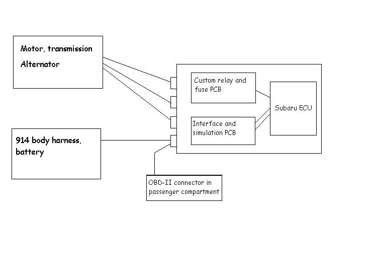
Posted by: scott thacher Jun 26 2005, 01:21 PM
the purge valve is on the engine harnes. the way it worked was the pressure sensor work thru a swotching solinoid that read intake pressure and atmosphereic pressure which were on the body harness. there where two valves on the engine one was the egr control the other is a purge valve for the tank fumes
at least this is how it si on pre 00 miles
Posted by: TonyAKAVW Jul 28 2005, 02:16 AM
Slowly but surely I've been making progress. The metal work on the car has slowed down a bit but in its place, the electrical work has progressed.
I finished the replacement for my relay board. It has a 5-position fuse block and three relays. One for system power, and two for each of the two radiator fans. There is room for a 4th relay for a heater blower, but that is an upgrade I will make when the time comes.
The new relay board is built inside of a weatherproof plastic housing with a hinged transparent lid. The box will mount to the side of the engine bay where the old relay board would sit. The box lid will open down for easy access to replace fuses or relays. I still need to drill a hole in the bottom for the wiring to go through and the large gray plastic Anderson Power conenctor will possibly be mounted on the bottom of the box. This connects to the alternator cable.
Posted by: TonyAKAVW Jul 28 2005, 02:17 AM
oops. forgot the picture...
Attached image(s)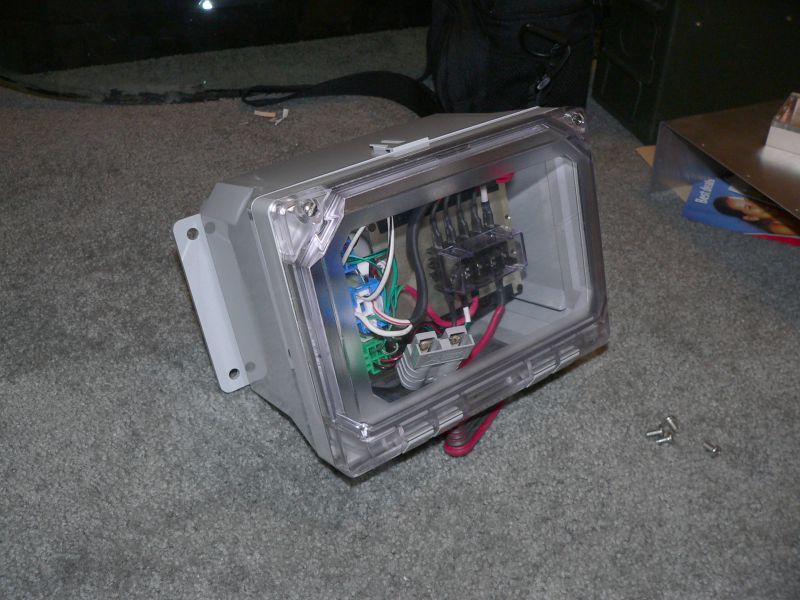
Posted by: TonyAKAVW Jul 28 2005, 02:17 AM
The guts.
Attached image(s)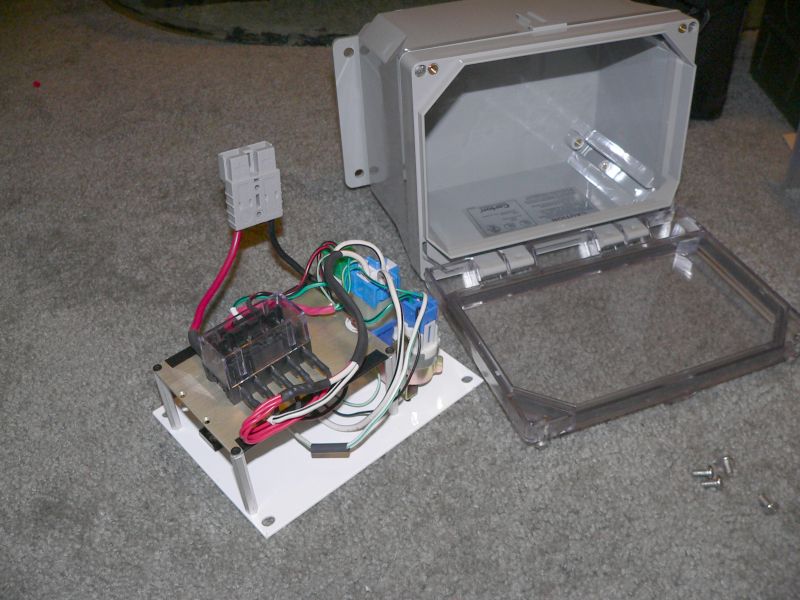
Posted by: TonyAKAVW Jul 28 2005, 02:22 AM
The next piece I have been working on isn't quite finished yet, but is close enough for some progress to be reported.
This box will sit on top of the ECU and simulate various sensors. The resistors are not in place, but the PCB is wired up and mounted to the housing. The PCB is unusual in color - white. Thats because the PCB is some scrap (expensive) ceramic/PTFE material that I had laying around. No particualr reason that its any better or worse for this application.
The housing is another piece of scrap. It once housed some kind of predistortion circuit for a microwave amplifier and probably cost more than what many of us payed for our 914s. Its a lovely chunk of hogged out and chem-filmed aluminum. The plastic lid I made myself.
There's a red LED indicator inside to show that the power supply for the sensors is active.
Attached image(s)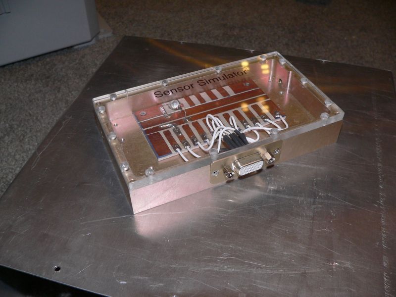
Posted by: turbo914v8 Jul 28 2005, 05:09 AM
Just curious, what sensors did you have to simulate. We are all enjoying your progress reports, Great project.
Posted by: mongrel-gs Jul 28 2005, 05:58 AM
That sure is a nice system for the relays and such!
Posted by: CptTripps Jul 28 2005, 06:08 AM
How have I been missing this thread?
Awesome work...I'm taking notes!
Posted by: TonyAKAVW Jul 28 2005, 10:21 AM
Okay, so I will be simulating the following sensors..
Fuel level sender (0.12 to 4.95 volts)
Fuel Temp sender (2.5 to 3.8 volts)
Fuel Tank Pressure sender (2.3 to 2.7 volts)
Rear O2 sensor signal (0 - 0.9 volts)
Neutral position sensor (+12 in neutral, 0 when in gear)
Rear O2 heater sensor signal (0-1.0 volts)
Power Steering oil pressure sender (open/close)
There may be one more, I'm still finalizing the wiring...
Most of these wil use small 10-turn potentiometers to set the desired signal voltage, but I may end up using real metal-film resistors in the end, as they are a bit more reliable.
-Tony
Posted by: phantom914 Jul 28 2005, 11:18 AM
| QUOTE (TonyAKAVW @ Jul 28 2005, 08:21 AM) |
| ...................., but I may end up using real metal-film resistors in the end, as they are a bit more reliable. -Tony |
Yes, please don't use the fake metal-film resistors, even though the low price may be tempting.
Andrew
Posted by: airsix Jul 28 2005, 12:54 PM
| QUOTE (TonyAKAVW @ Jul 28 2005, 12:17 AM) |
| oops. forgot the picture... |
Cool! With just a few minor tweeks you can make it look like the 'flux capacitor'. (Not making fun. I think it's great.)
-Ben M.

Posted by: TonyAKAVW Jul 28 2005, 02:24 PM
You know, Bondo mentioned that to me, that the box looks like a flux capacitor. Maybe I should put a label on it that says "Warning! Do Not Exceed 88 mph"
Making a gullwing 914 would be an interesting challenge.
-Tony
Posted by: scott thacher Jul 28 2005, 02:41 PM
the power steering pressure is not nessesary to fake it only closes when it loses pressure. but what you could do to make use of it is to connect it to a thermostat set at about 215 degrees, that way you get the extra signal ( cel ) if your temp goes high.
i also think you are going over board on the resisitor thing just intragrate them in to the harness
Posted by: TonyAKAVW Jul 28 2005, 03:20 PM
| QUOTE |
| i also think you are going over board on the resisitor thing just intragrate them in to the harness |
I am absolutely going overboard
But then I wouldn't do it any other way.
-Tony
Posted by: Kostamojen Jul 30 2005, 04:56 PM
Wow, nice work!
I'm a long time NASIOC member, and have a '95 Impreza with an MY2000 EJ25 conversion so this is a great read (Ive been looking at 914 stuff lately cause of the posts recently on NASIOC about the Renegage conversion, and the fact there is a 914 thats been forsale for like a year around the corner from my house ) That sensor simulator is a great piece, if you manage to get it to simulate both 02 sensors you can have alot of fun with the exhaust design
I was wondering if anyone has thought about using a cowel induction style intake with the N/A scoob motors on the 914's... There was a I-club member awhile back who had one using a PRM style intake filter, might be a neat idea for the swap.
As far as engine mounts go, I was curious whether you would be using the Subaru mounts or just bolting directly to your fabricated mount...
For everyone else looking into Subaru swaps, there are ALOT of very new very cheap motors (usually JDM imports) showing up now, vendors usually are selling them on the forums. Keep an eye out here if you are shopping for one: http://forums.nasioc.com/forums/forumdisplay.php?f=112 (Gruppe-S still has a brand new EZ30-R motor for ~$1500, the 250hp/215ft-lbs H6 from the new legacies, which gives me wicked ideas for a 914 conversion since it still uses the same motor mounts and such as the EJ motors... But I still think a verison 8 STI motor with its 8k redline combined with a high strung turbo would be a great motor for 914 but I dont think the tranny will take it  )
)
Posted by: TonyAKAVW Jul 31 2005, 10:40 AM
Welcome to the 914club!
Regardnig the sensor simulator, I won't be simulating the front O2 sensor. That is used by the ECU to run the enigne, whereas the second sensor is there just to verify the cat is working. Since I'm not going to be running a cat, I have to simulate the second sensor.
Don't really know what a Cowell induction is...
For the engine mount, I will be using the Subaru rubber engine mounts, which will be bolted to a roughly U-shaped bar which cradles the engine.
That EZ30 engine sounds like a great engine for a 914. I wonder if you could still fit it in the engine bay with the radiator back there. If so, that would be THE killer setup.
-Tony
Posted by: redshift Jul 31 2005, 01:37 PM
Tony... Tone... Toni... YOU ARE A NUT!
How cool is that!?
I swear, we don't even need cars to start with, we just need aluminum Chinese made copies, and the upper 2% of the club's brain trust to come up with awesome hardware to fill the holes with.
M
Posted by: Dr. Roger Jul 31 2005, 02:52 PM
 Hmmm, first time i've used that emoticon.. fun.
Miles,
I just followed your sig link Which lead me to another link.
Website dedicated to busting pervs.
Sick old pervs flirt with 14 YO girls on AOL chat, offer to pay them a visit or they visit the guys, and then nail them with the help from the cops. How cool is that?
"Want some candy?"... 
Posted by: Kostamojen Aug 4 2005, 05:28 PM
| QUOTE (TonyAKAVW @ Jul 31 2005, 08:40 AM) |
| Welcome to the 914club! Regardnig the sensor simulator, I won't be simulating the front O2 sensor. That is used by the ECU to run the enigne, whereas the second sensor is there just to verify the cat is working. Since I'm not going to be running a cat, I have to simulate the second sensor. Don't really know what a Cowell induction is... For the engine mount, I will be using the Subaru rubber engine mounts, which will be bolted to a roughly U-shaped bar which cradles the engine. That EZ30 engine sounds like a great engine for a 914. I wonder if you could still fit it in the engine bay with the radiator back there. If so, that would be THE killer setup. -Tony |
The cowel induction intake I mentioned was a little side project from a NASIOC member from a long time ago: http://forums.nasioc.com/forums/showthread.php?t=211038&highlight=intake Upon looking more at the 914 engine bay, it might not be a super great idea, but I'm curious now about what kind of intake designs people are doing with the scoobie engines...
As for the engine mounts, you might want to look into at least upgrading to STI engine mounts: http://www.rallispec.com/sub_drivemt.htm
Its not super expensive, but it may eliminate some concerns you have about engine movement. I mention this cause I saw that the other engine mount pic posted by Turbo914v8 and it looks like those might be the Group N mounts ($$$, also on that Rallispec page)
I dont think the radiator will fit in the engine bay with the EZ30, it is a tad bit longer than an EJ motor (But not THAT much longer, it fits in Impreza engine bays just fine)
Posted by: Burg Aug 7 2005, 04:26 AM
Hello, just a simple question from a newbie. If you do a suby conversion and you want to go turbo, which one would you prefer:
1. 2.0 WRX single turbo
2. 2.0 WRX STI twin turbo
3. 2.5 WRX STI single turbo
What do you think?
Burg
Posted by: TonyAKAVW Aug 7 2005, 12:17 PM
My first choice would be a US domestic market sinle turbo 2.5 liter STI engine because it puts out more power than the 2.0 single turbo and has much easier exhaust plumbing than the dual turbo. I didn't know Subaru made an STI twin turbo engine actually... I know that there is a Jpanese domestic market twin turbo (like the one fiid was trying to use) but I don't think its an "STi" engine.
The 2.5L STi engines are very expensive. From what I see/hear they go for between $5k and $8k !
For any of the turbo engines you will almost certainly need to mount the radiator up front.
-Tony
Posted by: Kostamojen Aug 7 2005, 01:55 PM
There really isnt such a thing as a WRX STI "twin turbo". The only cars that came with the twin turbos were foreign market turbo Legacies, and none of the current models use a twin turbo because of the developments in Twin Scroll Turbo technology. The JDM STI's use twins scroll turbos, as do the Legacies now. Its a much more efficient design that saves space and weight yet allows for alot of low-end torque because the twin scroll turbos spool at like 1500-2000rpms. Thats actually a good option if you want torque, even for a USDM WRX motor (IE the 2.0). There are a few folks who have run the twin scroll setup on WRX motors with great success (You can find the turbo, twin scroll piping, and oil pan all together for $1500, and use that with a WRX longblock which can be had for $1000 and you have a 300hp motor right there that spools very quickly). Although, im not sure how much torque you want in a 914 as I would think alot of low end turbo spooling would require rather large tires and a better tranny.
The other option is using a 2.5 USDM STI short block with whatever heads you want (WRX heads, JDM heads, etc.) which only costs about $1500 brand spankin new. Thats good for 30-40hp over a stock WRX motor right there, without spending the large amount of money for a full STI motor with all the goodies.
Theres another issue too with the new motors, especially the STI motor, and thats the electronic throttle. It pretty much requires you to use the proper ECU with that motor, and can make the pedal setup rather difficult. Ive also seen alot of issues with 05-06 motors now because of the Immobilizer built into the ECU's which will seems to be hard to get subaru support for, especially if you swaping it into another kind of car...
The twin turbo motors dont seem like a good idea to me for anything anymore, especially since there is ZERO support for this motor setup in North America.
I think if you arent going to do much with the tranny, a WRX motor with your choice of upgraded turbo would be ideal. Not too much torque and you can get it up to 200-300 wheel horse power if you want without too much trouble. A td05-16g or even the STI's VF39 are cheap options that I'd go with.
Posted by: mrdezyne Sep 11 2005, 09:47 PM
Just read this thread from begining to end....... I'm sold. Start looking for a donor EJ25 this week......
Great work on the details, write ups and valuable info! Please, by all means, keep it up. I'm soaking this stuff up like a sponge!
Being a mechanical engineer myself, all of your "over engineering" seems perfectly logical to me. True, you could just rush the job and wrap it all up with electrical tape but why not take the time to make it easy to work on later? Big Kudos!
And all of this with the cooling in the engine bay? Are you kidding me? Why not do the swap? This thing was made with the 914 in mind......
Posted by: TonyAKAVW Sep 12 2005, 11:36 PM
Time for an update.
I'm 95% done with my alternator bracket. I need to get a small amount of aluminum welding done, and hacksaw off an extra piece of metal and its done.
Conceptually my alternator bracket is similar to that of others who are doing/have done a Subaru conversion. Basically take the alternator and flip it over, out of the way of the intake, and build the 'adjustment' half of the bracket to hold the loose end.
The bracket was made in my father-in-law's machine shop in the outskirts of Buenos Aires. Thats right, I couldn't go for two weeks without doing some 914 related work. Lucky for me, my father-in-law is really excited about the projecct too. Last time he came up to visit he did some body work for me
Machining was done with a mix of tools, including my favorite, the vertical EDM, which we used to make precise internal right angle cuts, and the horizontal adjustment channel.
The original bracket which I took with me caused some problems at the Argentine customs. Upon X-raying my baggage the attendant asked me to pull out the offending metal piece. He held it for a moment, looked it over, asked what it was, still acted concerned, looked it over some more, and eventually gave it back to me. So if you ever want to take stuff in to Argentina, just pack a random piece of oddly shaped metal and it will distract them. Or maybe I just got lucky 
Anyway, on with the pictures..
Attached thumbnail(s)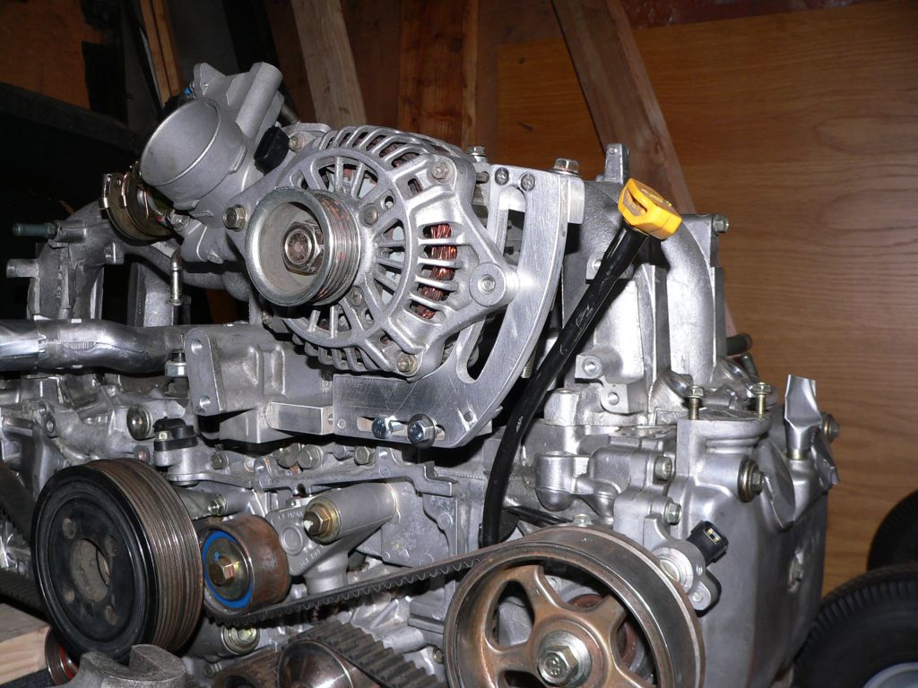
Posted by: TonyAKAVW Sep 12 2005, 11:39 PM
(referring to the above picture...)
My timing belt cover parts are in the mail... I'm replacing the belt, water pump and cover pieces before putting the engine in the car...
finally...
Attached thumbnail(s)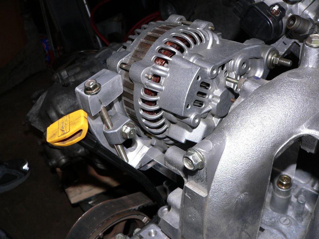
Posted by: scott thacher Sep 12 2005, 11:53 PM
toni does your engine have a iac valve and where are you putting it if it does ?
mount looks nice you should make a few
Posted by: TonyAKAVW Sep 13 2005, 12:30 AM
Yes, my motor does have an Idle Air Solenoid. Not sure where I'm going to put it, but I pretty much decided to do away with the stock tubing and hoses for air and fuel, and just start over with my own. So I'll find some place to mount it...
-Tony
I'll see if my father in law wants to do a small run of these.
Posted by: eric914 Sep 13 2005, 08:21 AM
I would be interested in one. Looks very stock.
Eric
Posted by: mongrel-gs Sep 13 2005, 09:31 AM
Wow! Thats much prettier than my version. If you ever end up making some extras you want to be rid of, let me know!
Posted by: andys Sep 13 2005, 09:50 AM
I briefly looked over Rennegade's Subie swap on display at the GAF in Ventura this past weekend. Motor fits very nicely, with nearly a foot of space between the firewall and the front of the motor. They made a sub frame that looked like it bolted to the motor mount crossbar mounting points, and the transmission mounting points. I'm not familiar with Subie motors, but his one had an intercooler so I assume turbo.
I avoided talking with Scott about it, as he's always trying to oversell everything....it's very annoying, though he's a nice guy. Anyone have any idea as to the cost of his Subie kit?
Andys
Posted by: TonyAKAVW Sep 13 2005, 10:05 AM
$2k gets you:
engine mount
rubber istolators
mount plates
mount blocks
billet adapter plate
custom flywheel
pilot bearing
throwout bearing
Kevlar clutch disc
pressure plate
hardware
Add another $1000 for the front radiator setup.
Posted by: firstknight13 Sep 14 2005, 07:16 PM
tony such a wealth of info thats what renegade wants so how much did you pay and what are the alternatives?? also i would take a bracket too!!!
Posted by: TonyAKAVW Sep 15 2005, 12:14 AM
Well, so far I'm into this for about $75 including the car, the engine, adapter, 5 lug setup, SC front end, etc. This is due to my repeatedly getting very very lucky...
But to break down the major costs so far...
Engine - $900 but needed maybe $200 in parts
Transmission adapter/flywheel - $250 used, off of Craigslist
I still have about $1000 in parts to buy before I get the car on the road, but this is more than just a conversion, I am taking a car from a rolling chassis to a fully running car.
I'm saving a lot of money by making my own engine bar and keeping the radiator in the engine bay, etc.
Regarding the brackets... I am going to draw up some plans based on my bracket, with some minor improvements and have my father-in-law figure out how to make them and get them shipped up here. I'll try and have some info soon on these.
-Tony
Posted by: TonyAKAVW Sep 27 2005, 11:25 AM
Update:
Still working on getting the timing belt installed. I made a stupid mistake of cutting off the old timing belt before aligning the timing marks. Because of this I have some uncertainty of where the timing is. So after consulting with Bondo, I decided to pull the oil pan off, rotate the crank to MDC, and then rotate the cams to their appropriate positions and then the crank to its position. The engine is an interference type, so I can't just freewheel everything into place without being careful.
Hopefully by end of tonight I'll have the timing belt on and install the cover, the crankshaft pulley, etc. I think now is probably as good a time as any to modify the oil pan and oil pickup tube.
Here's a photo of the motor's guts.
Attached image(s)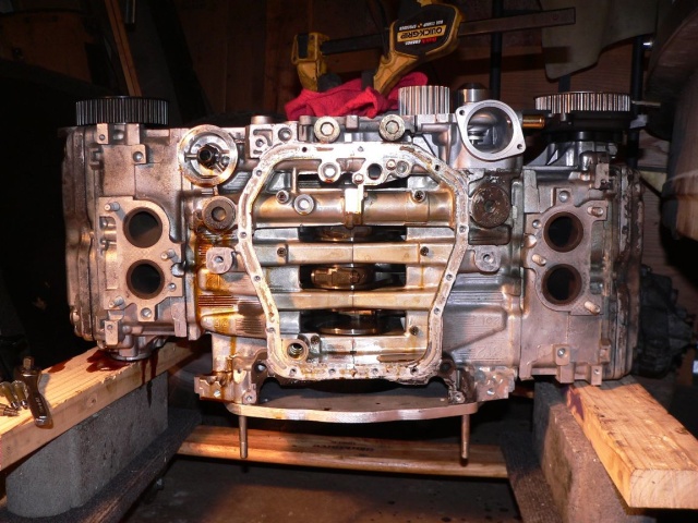
Posted by: TonyAKAVW Sep 28 2005, 04:02 PM
The timing belt is installed and the oil pan mating surface is cleaned up.
Left to do on the engine:
torque the crankshaft pulley
install the water crossover pipe
install the thermostat and water pump right angle pipe
bolt down the intake manifold
install fuel injectors and rails
do all the hoses on the engine and install misc. valves, filters, etc.
bolt down the throttle body
install oil filler neck
modify and install new oil pan and pickup tube
re-arrange the wiring to fit properly.
-Tony
Attached image(s)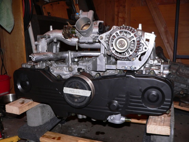
Posted by: Aaron Cox Sep 28 2005, 05:34 PM
bad ass alt bracket tony!!!
sooo over engineered!! 
Posted by: scottb Sep 28 2005, 07:12 PM
MORE MORE MORE!!!!
great pics and info tony.......
Posted by: TonyAKAVW Oct 4 2005, 11:55 PM
After working on the engine I am taking some time now to work on some other parts of the car which need attention. First up is the braking system which is essentially non existent.
I will be using A calipers on the front which came on the SC front suspension that I have. For the rears, I will be using stock 914 rear calipers but spaced to fit 911 vented rotors.
First things first though. Tonight I worked on the pedal cluster. I really need to send a couple parts to a sand blasting place. These will get powder coacted and re-assembled with new bushings. Because the brake light switch failed I am going to engineer a repalcement for it that whould be substantially cheaper than the repalcement 914 switch.
-Tony
Attached image(s)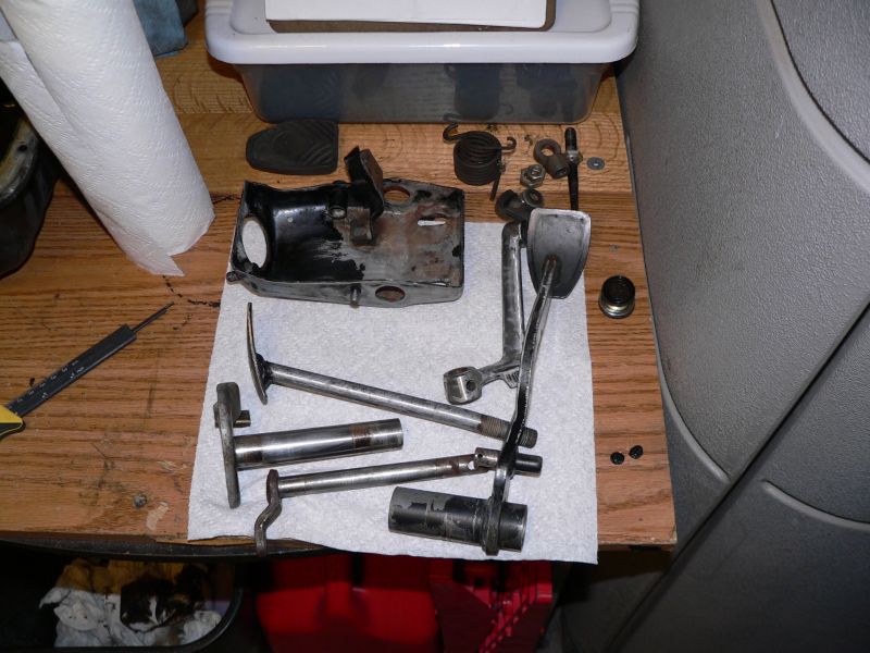
Posted by: TonyAKAVW Oct 5 2005, 12:01 AM
The last remaining arear on the interior of the car to be POR-15'd is the pedal cluster area, and tonight it got stripped down and got the usual pre-treatment. Might be able to get it painted tomorrow night.
-Tony
Attached image(s)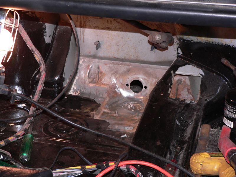
Posted by: TonyAKAVW Oct 9 2005, 11:21 PM
Got some stuff done today...
First, I met my favorite stripper. She's great. She takes EVERYTHING off.
Her name is Aircraft and she comes in a can. I used it to strip the paint off the subaru oil pan which I'm going to modify this week. Also used it to finish cleaning up the pedal cluster parts which then got a blast of phosphocrap and then POR15. I decided not to powdercoat because POR-15 is impervious to brake fluid unlike powder!
I did do some powder coating however and made a really quick and dirty oven. I took a piece of sheetmetal (rusty of course) and bent it into a U-shape and clamped it to my hand dolly, and set the propane heater in front of it. I then suspended the parts with teflon wire, (which is great for the powder coating and heat resistant for curing) and after coating baked them. I suspended an oven thermometer in the back, to ensure that I was getting to 400 degrees even at the back. Seemed to work quite well.
-Tony
Attached thumbnail(s)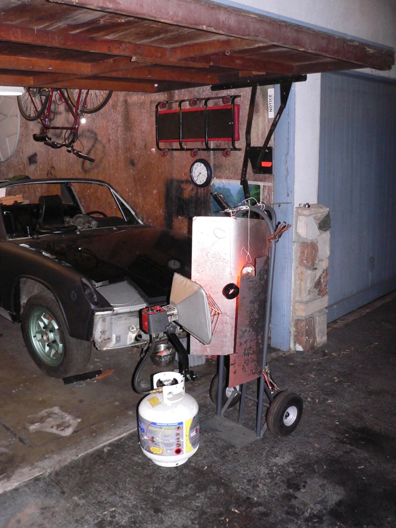
Posted by: TonyAKAVW Oct 9 2005, 11:23 PM
Inside the oven...
Attached image(s)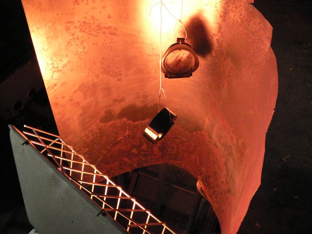
Posted by: TonyAKAVW Oct 9 2005, 11:35 PM
So here's what I was powder coating.
Andrew (Phantom914) gave me a steering wheel and a couple other pieces. One piece was a standard Momo-type adapter and the other was a spacer that he made from billet aluminum to adapt the "cheap 5 bolt Pep Boys type steering wheels" to the Momo adapter. Well the momo adapter was powder coated with some kind of black crinkle finish and had a big spot that was abraded. The spacer was plain aluminum and the bolt ring was some very dull powder.
Further, the horn button had a little "Auto Tecnica" emblem behind it. I decided this was lame, and printed up my own custom emblem. After putting it all together (powder coated the bolts to match too) it looks like this.
Clearly this is not something that is getting me closer to having my car on the road, but it was fun and will look pretty slick.
-Tony
Attached image(s)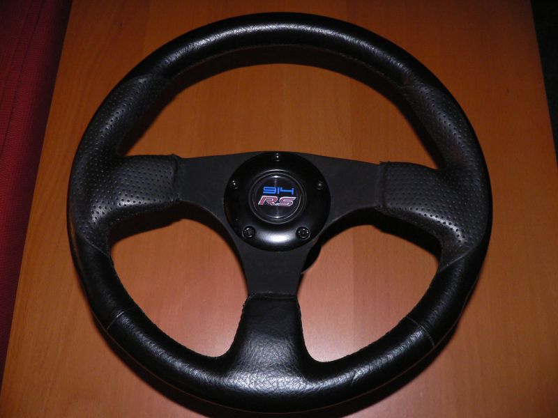
Posted by: TonyAKAVW Oct 9 2005, 11:38 PM
and the adapters...
Attached image(s)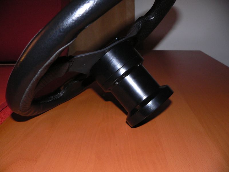
Posted by: sixnotfour Oct 9 2005, 11:50 PM
Cool Horn Button 
Posted by: TonyAKAVW Oct 21 2005, 01:27 AM
I was under the car tonight putting the engine into place and heard some weird noises. I got up and heard more noises from the shelves above me. There was some kind of animal up there but I had no idea what it was. Then all of a sudden this little bird appears and starts flying around. Because it was so bright in the garage he couldn't figure out how to escape. I eventually just shut off the lights and he flew right out.
Attached image(s)
Posted by: TonyAKAVW Oct 21 2005, 01:30 AM
So tonight I managed to get the engine and transmission into the car, aligned and ready for making measurements for the engine support bar.
I used a transmission jack that I bought for repairing my wife's car to move the transmission/engine assembly into the correct position.
Attached image(s)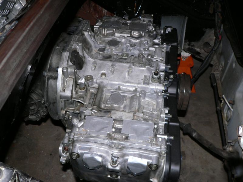
Posted by: TonyAKAVW Oct 21 2005, 01:31 AM
Here's the engine/transmission from beneath. You may notice that the oil pan is missing. That is currently undergoing a geometry adjustment. (making it shorter ro I can keep the engine low.
Attached thumbnail(s)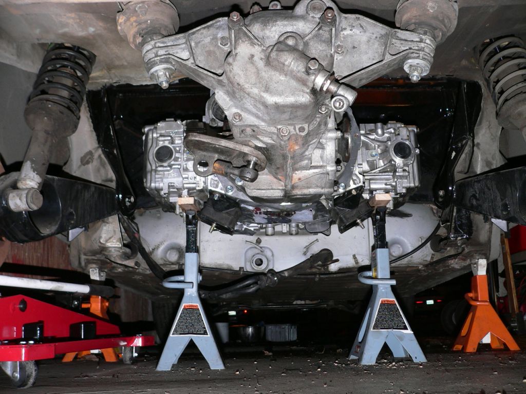
Posted by: banksyinoz Oct 23 2005, 02:17 AM
nice work tony keep up the good work
and thanks for keepin me motivated
the more i get motivated the more i fall in  with my 914
Posted by: TonyAKAVW Oct 27 2005, 02:28 PM
Okay, so I got my engine support bar back today from the welder. This engine support bar is made from 1.5 inch square steel tubing with a wall thickness of 0.075. The plates that the engine mounts bolt to are 1/2 inch thick and comprise a substantial fraction of the overall weight. However, these have a fair amount of stress on them, so I figured I'd make sure they aren't going to have problems.
I'll post measurements later, but the entire thing was made from a just under 5 foot length of tubing. I cut out 30 degree wedges at each of the bends. The 4th side of the tubing was left in place and I just bent the thing together. When I put it in the car to check out the mating, it fit very well on the first try. I held it in shape with some wooden struts that I bolted to the bar.
The welding cost $40, but I also took several other pieces, so I figure at most $30 to have this thing welded up, and another $10 or so in materials. Cutting was done with a hacksaw. I made a template for the angled cuts using some clear plastic acrylic pieces on which I scribed the angles with a knife. I used a few metal files to clean up the cuts and even them out.
-Tony
Attached image(s)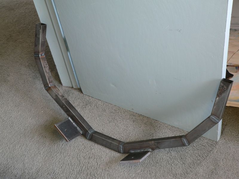
Posted by: banksyinoz Oct 29 2005, 04:24 PM
tony when you mget ur bar in can u post it as i am not quite undestanding  i guess but looks like the way that my engine was previously mounted
with the mount welded to theside of the car, where the yellow strip is in this pic,
your bar certainly looks the part though good work
Attached image(s)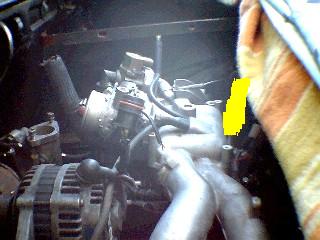
Posted by: TonyAKAVW Oct 30 2005, 09:25 PM
Hopefully the following pictures help clear it up...
Friday night I finally got the engine bolted into the car! The engine mount bar bolts into 1/4 inch thick steel plates on either side of the engine bay, at the point where the longitudinals finally reach the trunk firewall.
The following diagram shows the engine bar and the longitudinals and mounting locations. So yes, the bar mounts in the section colored yellow in your picture...
Attached image(s)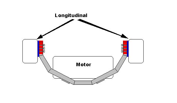
Posted by: TonyAKAVW Oct 30 2005, 09:28 PM
Okay, so the engine is now bolted into the car. At some point (hopefully) before I drive much) the plates need to be welded in and the 8 sheetmetal screws on each side removed and filled in with weld. For now though its good enough to roll the car around while I'm working on other things.
Also pictured is the super ricey AEM intake. I suppose I could just put the air filter right on the throttle body, but then there's no bright blue obnoxious tube in the engine bay
Attached thumbnail(s)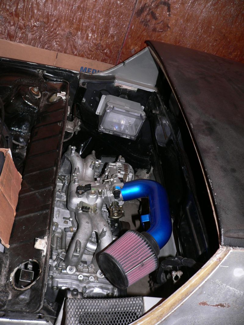
Posted by: TonyAKAVW Oct 30 2005, 09:29 PM
A view from beneath. The white stuff is excess metal ready that hasn't been cleaned off yet.
Attached image(s)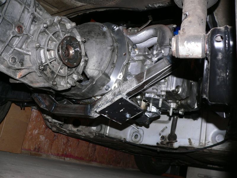
Posted by: TonyAKAVW Oct 30 2005, 09:31 PM
Detail of where the engine bar bolts to the plate. For now, the large bolts don't go all the way through. The firewall needs three large holes drilled out. Before the plates get welded on this will be done.
Attached image(s)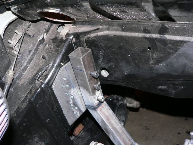
Posted by: TonyAKAVW Oct 30 2005, 09:34 PM
When I took the engine bar to the welder I held it in shape with wooden braces. Unfortunately they didn't hold perfectly, and the bar is out of alignment a little. On the driver's side its just a slight angle between the plate and the bar. On the passenger side there's a 1/2 inch gap which ahs temporarily been filled by a block of aluminum. Eventually I will get a half inch piece of steel in there and have it welded to the bar. Trying to fix the bar wouldn't be too much fun and would weaken it, so I'm going to live with it being slightly off, and the spacers that are needed.
Attached image(s)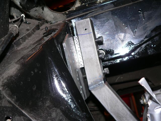
Posted by: TonyAKAVW Oct 30 2005, 09:35 PM
I also got the engine bay relay box installed. The electronics have been removed until I start wiring things up.
Attached image(s)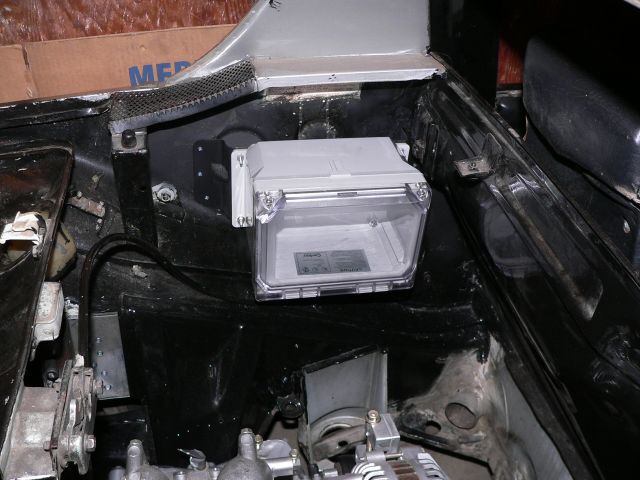
Posted by: TonyAKAVW Oct 30 2005, 09:38 PM
The last thing I got done this weekend was the oil pan lobotomy. I measured that I need the oil pan to be 4 inches tall based on the floorpan of the car and the engine support bar. This way the pan doesn't stick below the line and will be less likely to hit the ground in the event of a speed bump.
Pre-lobotomy, marked for incision.
Attached image(s)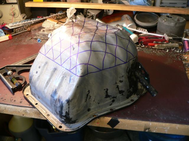
Posted by: TonyAKAVW Oct 30 2005, 09:40 PM
Post-lobotomy. Next thing to do is fill up the leftover piece with water and measure how much extra volume I need to add. I've been thinking about different ways to do it, including the use of tubes running through the new volume for screw access. I suppose this depends on how good a welder this guy is...
-Tony
Attached image(s)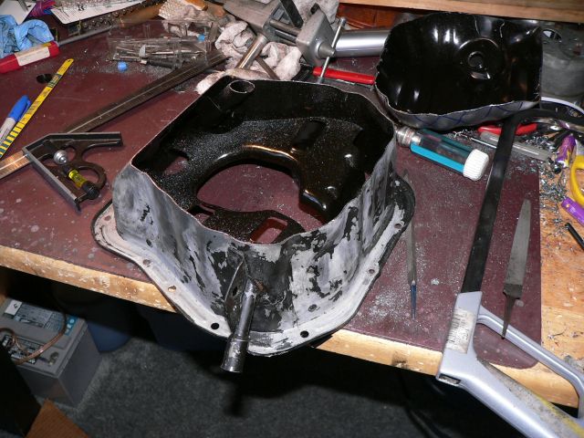
Posted by: jkeyzer Oct 31 2005, 01:30 AM
A few comments from the peanut gallery (for discussion):
1. Why make the bar a segmented U instead of a rectangular shape? Is there a strength benefit?
2. Is it really necessary to use 1/2" steel plate at the points where the bar hits the engine? If you had welded the bar forward a little, are the plates even necessary at all?
3. Is it safe to hang the engine from those tiny sheet metal screws?
4. Instead of drilling lots of holes in the longs for the thru bolts, why not weld the bar to the side plates?
5. Why use a spacer on one side when you could heat the bar up with a torch and bend it into shape?
Otherwise it looks great but you might want to consider #4 and #5 while it is easy to change things? Do it right the first time. I would rather have a weld supporting the engine than the sheer strength of a few bolts.
Posted by: banksyinoz Oct 31 2005, 01:51 AM
thanks tony its appreciated
my engine is currently mounted in a simillar fashion but i will be changing it as i have the suby box
your work looks great keep it up, could you please post the volume of the removed section of the sump just as an example of the approx ammount to be replaced, i have considered extending my sump volume forward as this will mave the turbo brain more simple for the ej20t
yes plate size good
yes bar thickness ample
welding in bar would obviously be thoughtless for engine removal
what sheet metal screws ,there not sheet metal screws officer
Attached image(s)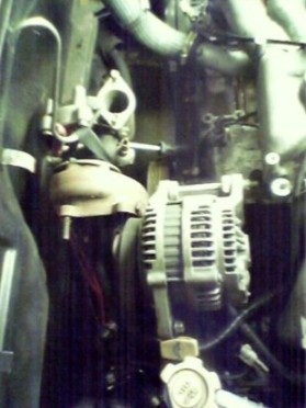
Posted by: TonyAKAVW Oct 31 2005, 11:19 AM
Okay, to answer some questions/concerns...
From Jkeyzer:
1. U-shape is stronger, and doesn't interfere with the trailing arm movement. A straight down piece would blockk the trailing arm from going where it should when going over bumps etc. Also, the engine mounts on the motor are angled down at 30 degrees so it would be more complex to mount them to a straight across bar.
2. Not sure if 1/2 inch is necessary, but 1/4 inch might be too little. The engine can't really be bolted any closer. The pictures I have shown here are of the passenger's side. The driver's side head on the engine sits back further towards the output flange, and there is maybe 1/4 to 1/2 inch of clearance on that side between the support bar and the head.
3. For now yes.
4. Welding the bar into the side plates, as banksyinoz mentioned would make for a very difficult engine removal. By welding paltes onto the longitudinals, I am effectively increasing the strenght of them in that local region. The sheetmetal of the longitudinal at that point doesn't carry the majority of the load. The plate spreads it out.
5. The spacer will be welded to the engine bar, and actually it will make the structure stronger... Since it becomes an integral piece of the bar, it allows for half an inch of material for the bolts to sit in. I'm really not sure how heating up the bar would allow me to bend it. Bending isn't going to help unless its the entire thng and that would take a TON of heat. Also, what happens to the metal after I heat it like that???
Because I'm using 3 3/8 inch bolts going through solid metal (the inside of the tubing at the tops is going to be filled with a machined aluminum billet) I can really crank the bolts down and get a huge amount of strength on each side. I'm not too worried about the conenction point, its not as if this engine has a V8s worth of torque. But I will watch it and see how it goes.
Okay.. next..
The volume of the oil pan that I removed is 1.1 liter or about 67 cubic inches. So it loses 1 quart of oil basically. I can make that up by adding roughly a 4 by 4 by 4 section, but I will probably do it on either side in a 4 by 2 by 4...
-Tony
Posted by: jsteele22 Oct 31 2005, 04:21 PM
Hey Tony,
Great to see you (& fiid) making progress. Always love to see pictures ! That's the best shot I've seen of the oil pan situation. Man was that thing deep or what ! I'm wondering if anyone has tried just closing off the pan with a flat sheet and adding the volume externally; like maybe using a remote-mounted dual oil filter. The combination of going from 1 to 2 filters, using a larger that stock size filter, and the tubing itself should probably make up the 1.1 liters.
BTW, is that the dipstick tube coming out of the pan ? Also, is there an oil pickup tube from the engine that has to get shortened ?
Keep up the good work. I'll need to hear plenty of happy stories to keep me going on my project. I'm still waiting on the engine (seller had a roof collapse which caused some delays...) and I'm gonna be pretty busy until the end of the year, at least, with other stuff.
Posted by: TonyAKAVW Oct 31 2005, 05:01 PM
| QUOTE |
| Great to see you (& fiid) making progress. Always love to see pictures ! That's the best shot I've seen of the oil pan situation. Man was that thing deep or what ! I'm wondering if anyone has tried just closing off the pan with a flat sheet and adding the volume externally; like maybe using a remote-mounted dual oil filter. The combination of going from 1 to 2 filters, using a larger that stock size filter, and the tubing itself should probably make up the 1.1 liters. |
Thats a really interesting idea... I had been thinking of just putting two fittings on the oil pan and having an extra can for the oil. It would be the least fabrication, but I'm thinking that the oil would sorta get trapped in there and not cirulate much.
I will have to look at the engine and see how I could fit two filters, etc.
| QUOTE |
| BTW, is that the dipstick tube coming out of the pan ? Also, is there an oil pickup tube from the engine that has to get shortened ? |
Yes, that is a dipstick tube coming out of the pan, and yes, the pickup tube has to be shortened a bit. Another neat trick that Outback motors does on their modified pickup tubes is to weld a little bar across the opening of the tube so that in the event of a minor oil pan denting incident, the pickup tube doesn't bottom out on the floor of the oil pan and suffocate the engine.
Good luck with your project. I has been just about 2 years now since I picked up this car and started working on it. But only in the last few months have I really built up some momentum.
-Tony
Posted by: cha914 Oct 31 2005, 05:34 PM
Looks good Tony. I thing for the oil pan I would just weld a flat piece on the pan and then add an accusump to the motor, you have plenty of space in the engine bay for it, and you could get away with a small 1 or 2 qt one easily.
Keep the pics coming!
Tony
Posted by: jsteele22 Nov 1 2005, 10:55 AM
| QUOTE (TonyAKAVW @ Oct 31 2005, 04:01 PM) |
Thats a really interesting idea... I had been thinking of just putting two fittings on the oil pan and having an extra can for the oil. It would be the least fabrication, but I'm thinking that the oil would sorta get trapped in there and not cirulate much. I will have to look at the engine and see how I could fit two filters, etc. |
I'm not sure what an accusump is, but this was the sort of thing I had in mind.
http://store.summitracing.com/default.asp?target=partdetail.asp&autofilter=1&part=SUM%2DG4986&view=1&N=4294925232+4294839075+4294817872
Posted by: banksyinoz Nov 1 2005, 03:51 PM
had the same thought on the filter as there can be a cooler added as well in the line (my ae82 twincam (4age) toyota corolla has this setup) but the main reason was for ease of the custom exhaust manifolds
this would mean larger oil volume plus water and air cooling for the oil ,which cant hurt when raping occurs 
tony will you also support your engine bar forward to the original mounting point ? i just think it would help strengthen the mount and stop it flexing forward and back? just a thought 
Posted by: TonyAKAVW Nov 1 2005, 05:00 PM
I had no idea what an accusump was either... so for those who don't here's the basic idea behind it...
An Accusump is basically an oil accumulator - a cylindrical canister with a large piston inside. On one side of the piston is a compressible gas (air) and on the other side is room for oil. When the oil system pressurizes, the pressure forces the piston back and the accumulator fills with oil. When a loss of oil pressure occurs, the air pressure pushes the piston and oil is forced out.
There are a couple uses for this. First is that with a manual valve, it can be used to pre-oil an engine. So when you stop running your car, you close the valve, and the cylinder is filled with pressurized oil. Just as you start up the car, you open the valve and the pressurized oil is forced into the engine and lubricates everything as oil pressure builds up normally.
The other main use is for conditions where the oil in the pan is sloshing around and the pump is sucking air. In this case, the pressurized oil feeds the system until pressure is regained and things go back to normal.
I do like the idea of having a relocated filter, or maybe even a pair of filters, but I'm wondering if this really fixes my problem. Bondo claims that the filters are after the oil pump. So if the pump starts suffocating, the extra volume post-pump doesn't seem as though it would help a whole lot. Is this the right way to think about it?
-Tony
Posted by: banksyinoz Nov 1 2005, 05:22 PM
when i looked at my sump yesterday there seems to be room to go forward and back with the volume as in 500ml on the front and 500ml on the back to make up for the 1lt approx on the bottom that is removed.
from your pic of your engine bar i would guess that you also have similar room to add this, then the volume is in the sump as it originally was , some extra windage may be of help in this scenario though this maybe a little more tinwork but less cost
Posted by: d914 Nov 1 2005, 05:37 PM
from outback, thought it might help:
The easiest way to do this is to chop off 1 1/2" of the pan on the bottom. Since the original design of the motor places the oil a good distance below the crank, when using our chopped oil pan the motor still accepts 5 quarts of oil with no risk of oil aeration. If using the stock dipstick, the full mark is the low mark,
The best value for a shortened oil pan is Outback's "ready to mount" pan with heavy duty 3/16" this plated bottom. This is fabricated from at standard oil pan, chopped off and welded into place the new rugged bottom. This bottom is welded into place with slight tilt so the oil will drain nicely to the drain hole. The drain plug is in the rear of the pan (flywheel side) toward the bottom. Kit's for this area available too if you want to do the work of chopping and welding yourself
Posted by: bondo Nov 1 2005, 06:13 PM
The whole point of a sump is to keep the air out of the oil system, and provide some reserve capacity. Adding filters won't do that. You could add 20 filters and you would require more oil, but it won't add the equivalent of sump capacity.
Posted by: TonyAKAVW Nov 1 2005, 08:37 PM
GRRR. I HATE UPS. I don't use UPS much, but one time a package was completely lost, and now this time it got damaged. Question is, will this still work?
Attached image(s)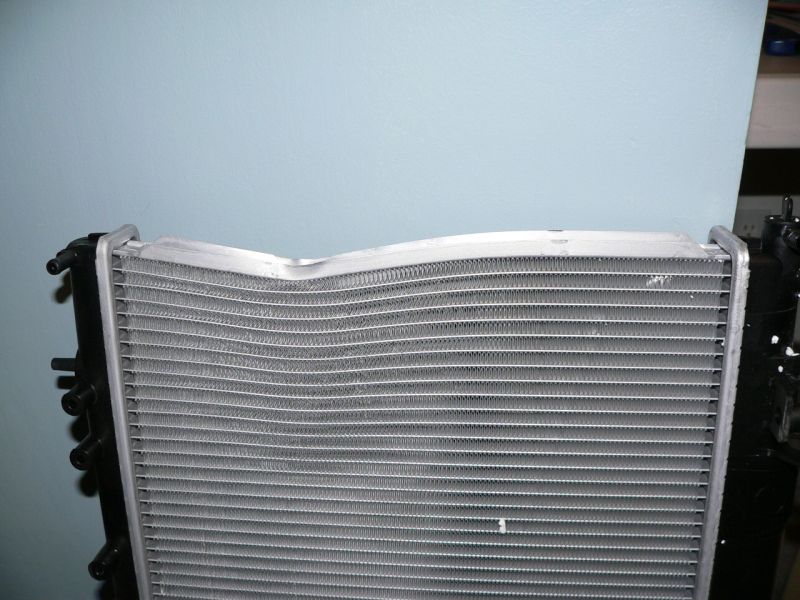
Posted by: dlo914 Nov 1 2005, 08:42 PM
i dont like UPS as well...shipping fees are like double that of USPS.
UPS=Universal Piece of SH*T
Posted by: bondo Nov 1 2005, 08:44 PM
| QUOTE (TonyAKAVW @ Nov 1 2005, 07:37 PM) |
| GRRR. I HATE UPS. I don't use UPS much, but one time a package was completely lost, and now this time it got damaged. Question is, will this still work? |
It'll work great on a stock 914, but not a subie one.
Posted by: CptTripps Nov 2 2005, 09:25 AM
I wouldn't trust it as far as my dog could throw it...
...file a claim.
Posted by: jsteele22 Nov 2 2005, 04:19 PM
| QUOTE (bondo @ Nov 1 2005, 05:13 PM) |
| The whole point of a sump is to keep the air out of the oil system, and provide some reserve capacity. Adding filters won't do that. You could add 20 filters and you would require more oil, but it won't add the equivalent of sump capacity. |
Okay, good point. I was just thinking in terms of volume. From what I've seen here, this is my understanding of the situation :
1) dual remote mount oil filter
PRO: increases the volume of oil in the system, ads a tiny amount of oil cooling, makes filter changes easier.
CON : does not keep the oil pickup tube from sucking air.
2) Accusump.
PRO : looks cool, smooths out pressure fluctuations, can be used to pre-oil engine.
CON : $$$, does not keep air out of oil circuit.
YEAH BUT : If air does get sucked in, it will be compressed and forced through the system by the reserve of pressurized oil. Isn't this good enough ?
3) Fill the oil pan to a higher level
PRO : keeps the oil pickup tube end covered, so air doesn't get sucked in.
CON : top of oil is that much closer to crank
4) Fabricate a larger volume (expanded sideways) oil pan
PRO : you get more volume
CON : hard to do, and it looks like the risk of sucking air is exactly the same as case (1) and (2).
So I've still got some questions :
* How serious is it to momentarily draw air into the system, by going over a bump, say ? Once the pickup tube gets re-submerged, the oil will eventually push the air through, but in the meantime are we talking a negligible increase in wear or a destroyed engine ?
* How serious is it for the crankshaft to (occasionaly) splash into the oil ? Sure, you'll lose a little power, but are there any other bad consequences ? Someone mentioned foaming ? I was always told that overfilling an engine's oil, which is essentially what (3) amounts to, can do (unspecified) bad things. Urban Folklore ?
Posted by: MikeP Nov 2 2005, 05:20 PM
Running the crank into the oil has the same effect as riding a bike into water. check to see if you can get a windage tray for your application as they work to "scrape" oil from the crank, prevent some of the "foaming"and provide a slight barrier to oil slosh, they bolt on to extended main studs, in a SBC they can give a rather significant HP gain as well.
Posted by: TonyAKAVW Nov 2 2005, 05:32 PM
Here's the bottom of the engine looking inside. The crank is above the top of the oil pan considerably.
Attached image(s)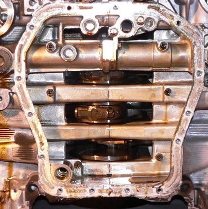
Posted by: TonyAKAVW Nov 2 2005, 05:33 PM
And here it is with the windage tray in place. I suppose that blocks some of the oil splashing.
Attached image(s)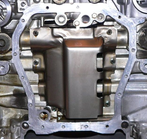
Posted by: Mueller Nov 2 2005, 05:50 PM
Tony....drysump it....you got access to machine tools correct?
Attached image(s)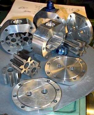
Posted by: TonyAKAVW Nov 2 2005, 05:54 PM
| QUOTE |
| Tony....drysump it....you got access to machine tools correct? |
You know that was my thought originally, but I have no idea how to make a dry sump system. And as far as machine tool access... kinda sorta, not really, maybe, depends. I suppose I should do some reading on dry sumps. Unfortunately I have several other items up my sleeves that I need to work on first... But a dry sump is definitely a cool idea...
See Mike, this is why you need to get rid of that air cooled engine and convert to Subaru. Think of all the wonderful parts you could come up with!!!
-Tony
Posted by: lapuwali Nov 2 2005, 06:01 PM
The hardest part about a dry sump is the tank, and you can buy those. The rest is simply a matter of adding a second oil pump (can be a belt-driven external unit) that pulls oil out of the much-shortened "sump" and pumps it into the tank. The drain for the tank then feeds into the pressure pump. There are external pump assemblies available that supply both the scavenge and pressure pumps in one housing, and you simply remove the stock oil pump.
Posted by: TonyAKAVW Nov 4 2005, 01:45 AM
I decided to use the messed up radiator for making measurements and building a frame.
Attached image(s)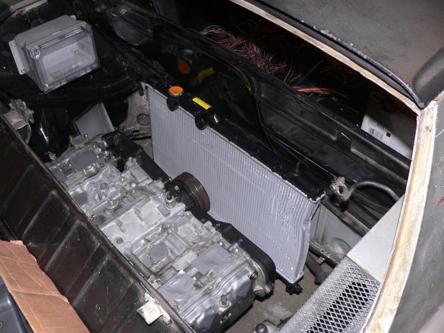
Posted by: TonyAKAVW Nov 4 2005, 01:47 AM
Here's the frame. Its made from 1 inch wide angle stock, held together for now with screws. Eventually it will be welded together.
Attached image(s)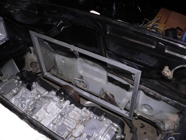
Posted by: TonyAKAVW Nov 4 2005, 01:53 AM
Here are the side pieces taped into place for fitting. The top piece is a much more challenging part and I still need to figure out a way to cut it to the correct shape.
Attached image(s)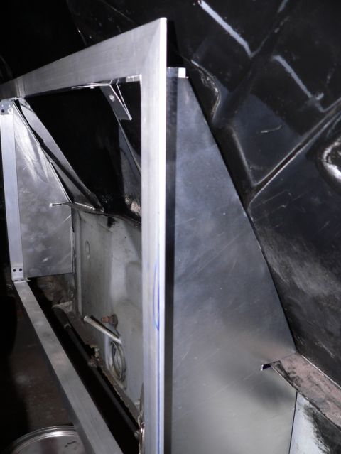
Posted by: jsteele22 Nov 4 2005, 11:22 AM
| QUOTE (TonyAKAVW @ Nov 2 2005, 04:32 PM) |
| Here's the bottom of the engine looking inside. The crank is above the top of the oil pan considerably. |
Wow, great shot. I nominate you for the 914club Annie Liebowitz prize.
I had been trying to picture what that area looked like, and I was sure that something would protrude down into the sump (besides the pickup tube.)
Tony, is that windage tray you show a stock part of the Suby engine ? (If a little piece of stamped sheet metal makes that big a difference, WTH doesn't every car come with one ?)
So, I know its crazy, but Mike's other thread has gotten me all worked up about a dry sump system. Sort of a hypochondriac's version of DWD.
Posted by: TonyAKAVW Nov 4 2005, 12:39 PM
| QUOTE |
| Wow, great shot. I nominate you for the 914club Annie Liebowitz prize. |
Thanks!
Yes, the windage tray is part of the stock Subaru engine. The type IV has a similar plate, so I don't know which engines have them and don't. Seems like a pretty inexpensive item.
And yes, that dry sump idea sounds really cool. I'm definitely interested in that, but I think for the time being I will go with a modified oil pan. If I start taking on new projects like that I'm never going to get this car on the road.
Something interesting I found out when placing the radiator is that if you mount the radiator to one side of the engine bay, there would be plenty of room on the other side for one of those large oil sump tanks!
-Tony
Posted by: Goge Nov 4 2005, 01:04 PM
Hey Tony-
I decided I'd quit lurking and finally post something...
Would that rad fit in there if the lower sheet metal weren't cut away? It doesn't really look like it but I can't quite tell. Just curious.
I'd like to do this dance eventually myself, but would like to keep cutting to a min... I don't think I could carve up my car very much and still sleep at night. But if i could get away with a few mounting holes for the motor mount and the rad, I might be able to catch a few winks without too much guilt.
Thanks for answering a couple questions via e-mail the other day, too!!
Keep up the good work there, I'm living vicariously through you!
-Todd
Posted by: airsix Nov 4 2005, 05:06 PM
| QUOTE (Goge @ Nov 4 2005, 11:04 AM) |
| but would like to keep cutting to a min... I don't think I could carve up my car very much and still sleep at night. |
Todd, I used to feel that way too, but you get numb to it eventually. I can dive in with an air-chisel or other instrument of mass destruction now without even giving it a second thought.
-Ben M.
Posted by: Goge Nov 5 2005, 12:35 AM
Ben-
You're certainly correct. I could maintain my (unperfect, underpowered) '72 in all it's debatably stock glory, and get hit by a Hyundai next week. Or, I could do a little choppin' and multiply horses by about 2 (holy crap!!!!) and work on putting in a Soob motor. And I think that would be more fun to drive (even if the Hyundai still mowed me down later on, at least I'd have had the fun).
I had better quit posting, because I'm at least a year away from undertaking this... and it's Tony's thread.
But I'm taking baby steps, fixing rusty areas over the winter. I was pleasantly surprised when I finally took off the outer rocker after owning this thing for 10 years! Not bad! This was taken just after I took it off, only a little surface rust. And a lotta dirt. And a hazelnut fell out, too (a 'filbert' if you live around here....)
Have at it, Tony. We're watching...
Attached image(s)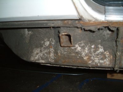
Posted by: CptTripps Nov 6 2005, 07:57 AM
I've got a Vespa to do this winter, but I'm thinking *NEXT* year I'm going to drop a Soob in mine too...
Something about 200hp, and getting to keep both trunks.
Posted by: TonyAKAVW Nov 6 2005, 10:41 PM
Made a little progress this weekend... My main project this weekend was replacing the front pads and rotors, as well as an oil change on my wife's TT.
The remaining piece of radiator shroud was cut today and installed. All that is left now for the radiator frame is some bracketry for suspending the radiator itself. This too will be made from angle-stock. Once this is all complete I should have measurements and drawings up for others to duplicate.
Another bit of good news, is that the infamous alternator bracket I made is out for reproduction, so hopefully there will be some even slicker custom alternator brackets coming out soon.
-Tony
Attached image(s)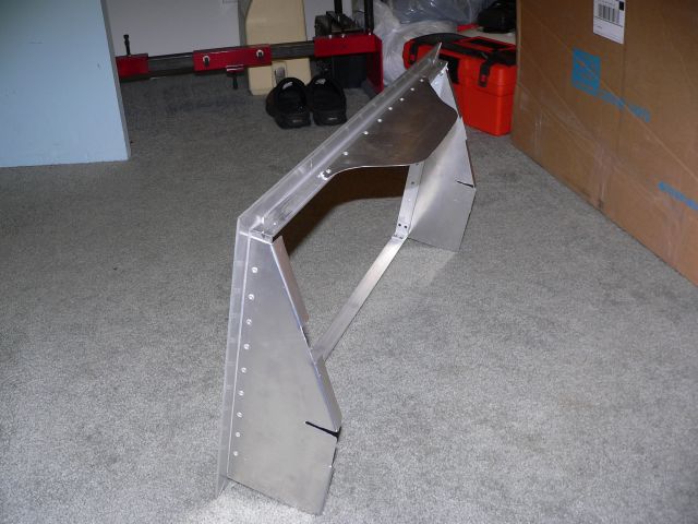
Posted by: Aaron Cox Nov 6 2005, 10:43 PM
tony. your sheet metal work rocks!
can i pay you to make an oil cooler shroud for me?
Posted by: TonyAKAVW Nov 6 2005, 10:45 PM
The top piece was made in an interesting way...I needed the shape of the tin to conform to the indent on the firewall between the two seats. I put the radiator frame in place and then applied masking tape to the wall and then sprayed some expanding foam into the gap. This provided a pretty good template for tracing out the top piece. Unfortunately it wasn't perfect and I had a bit of filing to do to get it right. Its pretty decent but there are some small gaps still.
This picture is of the foam block (ecased in masking tape) ready to trace out onto the aluminum sheet.
-Tonyi
Attached image(s)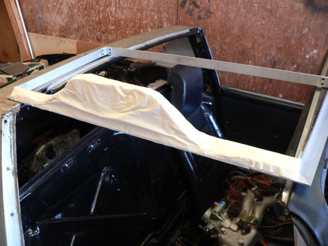
Posted by: TonyAKAVW Nov 6 2005, 10:49 PM
| QUOTE |
| tony. your sheet metal work rocks! can i pay you to make an oil cooler shroud for me? |
My sheetmetal work is only awesome in the 640 by 480 resolution
I did this with a $12 nibbling tool from Radio Shack, a pair of tin snips, and a fairly small bench vice. If you want a shroud, bring your car by some weekend and we can make one. Should be pretty easy. -Tony
Posted by: Aaron Cox Nov 6 2005, 10:59 PM
| QUOTE (TonyAKAVW @ Nov 6 2005, 09:49 PM) | ||
My sheetmetal work is only awesome in the 640 by 480 resolution I did this with a $12 nibbling tool from Radio Shack, a pair of tin snips, and a fairly small bench vice. If you want a shroud, bring your car by some weekend and we can make one. Should be pretty easy. -Tony |
you got it man.
Posted by: phantom914 Nov 6 2005, 11:01 PM
| QUOTE (Aaron Cox @ Nov 6 2005, 08:59 PM) | ||||
you got it man. |
Tony accepts only frozen pizzas as payment.
Andrew
Posted by: Aaron Cox Nov 6 2005, 11:06 PM
i thought you had to have a 914 to post here
hey andrew 
Posted by: bondo Nov 6 2005, 11:44 PM
| QUOTE (phantom914 @ Nov 6 2005, 10:01 PM) |
| Tony accepts only frozen pizzas as payment. Andrew |
Hahahaha!


Posted by: TonyAKAVW Nov 14 2005, 01:26 AM
Okay, some progress on the radiator shroud. Lots of minor improvements and little tricks to this...
Here's what it looks like now. On the sides are adjustable angle pieces that keep the air from shooting out to the side of the radiator. They are adjustable so that I can tighten them to whatever radiator goes in (the replacement for my crappy ne may be very slightly different) and I can account for any skew as well...
There are also mounts now for the top and bottom of the radiator to hold it in place.
More details below...
-Tony
Attached image(s)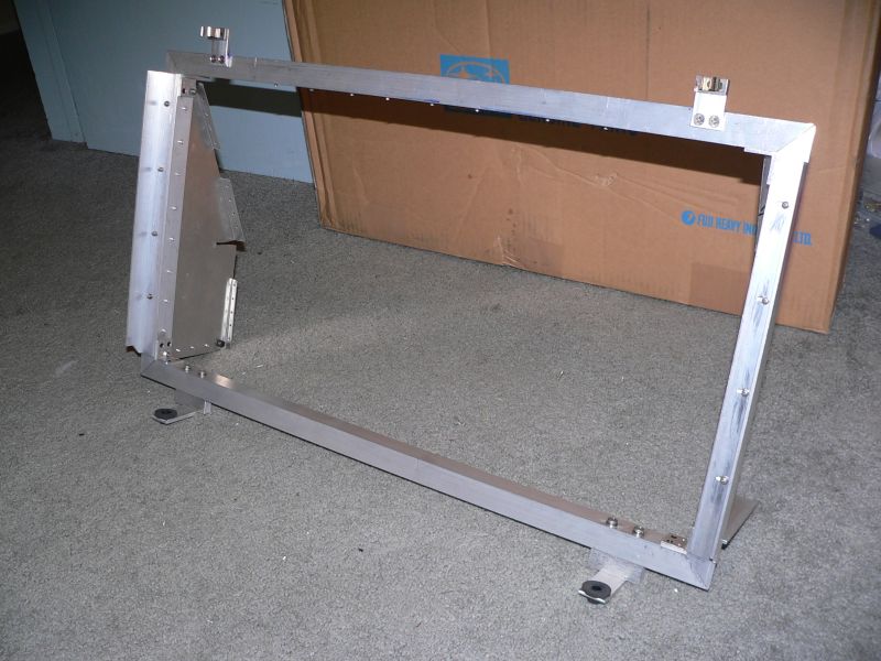
Posted by: TonyAKAVW Nov 14 2005, 01:29 AM
At the bottom of the frame are two legs that stick out, and they have holes drilled in them to accept the peg that sticks out from the bottom of the radiator. I bought some rubber grommets and some foam rubber gaskets at Industrial Liquidators for isolation dampening.
Attached image(s)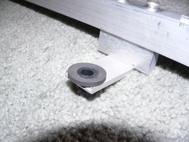
Posted by: TonyAKAVW Nov 14 2005, 01:32 AM
At the top are clips that hold the radiator in place by the pegs from the top...
Attached image(s)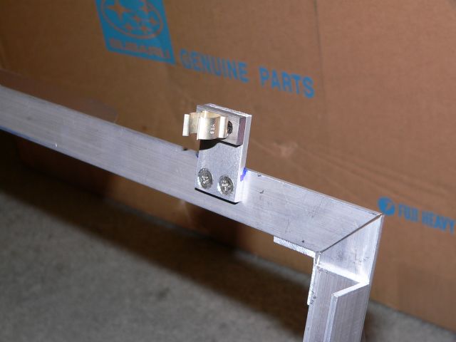
Posted by: TonyAKAVW Nov 14 2005, 01:32 AM
Now with the radiator in place...
Attached image(s)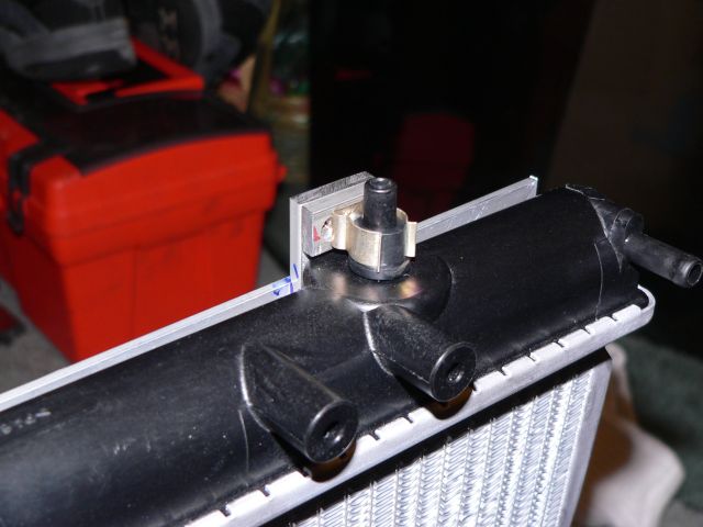
Posted by: TonyAKAVW Nov 14 2005, 01:34 AM
Some holes for rivets to hold the frame onto the firewall. At the bottom is a support piece which mounts to the firewall via a welded on angle-iron segment. (hard to explain, will show with picture when it is installed later)
Attached image(s)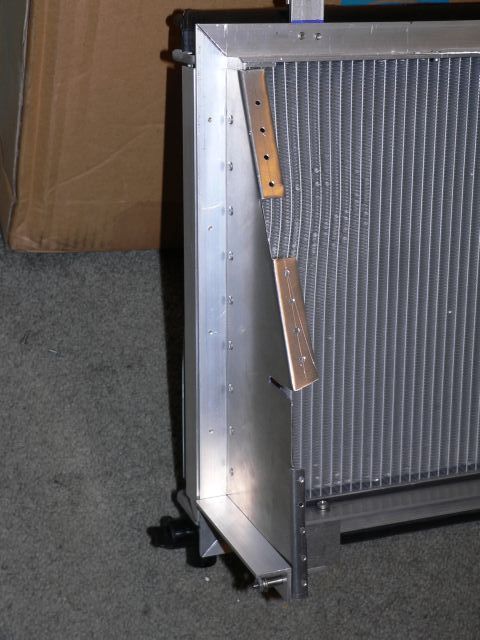
Posted by: TonyAKAVW Nov 14 2005, 01:35 AM
Last but not least, a bit more on the mounting methdo from the last picture. Use your imagination for now as to what the element on the car is going to look like.
As a final note, this whole thing is going to be welded up by a neighbor. There are a ton of screws holding pieces together. All of those will go away. The rivets howwever will stay. After that it will be powdercoated black. Or, if anyone wants to anodize it for me, that would be cool
-Tony
Attached image(s)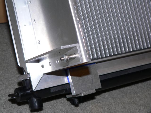
Posted by: phantom914 Nov 14 2005, 11:38 AM
Looks cute!
Andrew
Posted by: bondo Nov 14 2005, 12:07 PM
Somebody needs a TIG welder.
Posted by: TonyAKAVW Nov 16 2005, 12:42 AM
Last night I sprayed some expanding foam around the perimeter of the oil pan. The purpose of this was to figure out where to expand the oil pan to increase volume but at the same time not interfere with installing it, or other things in the vicinity like the engine mounts, oil filter, and engine support bar.
Attached image(s)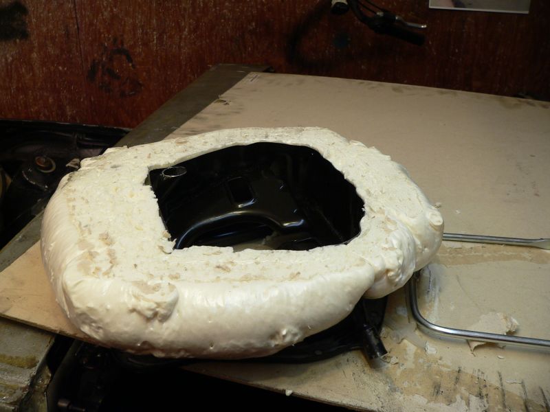
Posted by: TonyAKAVW Nov 16 2005, 12:45 AM
So I cut pieces out of the foam for a few major sections.
1. Front
2. Rear
3. Sides
I can get probalby 2/3 of a quart with the front and rear, this is _probably_ enough. When I cut off the bottom I removed 1 quart's worth.
I got crazy with the bondo tonight and covered the front and rear pieces, sanded and painted them.
-Tony
Attached image(s)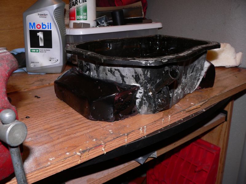
Posted by: banksyinoz Nov 16 2005, 05:37 AM
the sump, thiught that you might put the volume on the front and the back, this would suit the turbo on mine also
ie the oil drain 
Posted by: TonyAKAVW Dec 6 2005, 01:13 AM
The only new thing to report is that I have decided to abondon the conversion of the silver roller pictured in this thread. Instead, I am going to convert my '70 1.7 daily driver to Subaru. What I will continue doing though is finishing the parts for the conversion on the silver roller. On my list of things to finish soon are a lot of little things, and a few large ones such as modifying the oil pan, etc.
This will hopefully speed things up a bit, as I don't have to complete a full restoration in addition to the subaru conversion stuff.
So witihin a month or two I'll have the silver body for sale. It won't come with a suspension, it will just be a bare body in need of some work.
More updates to come very soon I HOPE!!!
-Tony
Posted by: Goge Dec 6 2005, 01:51 AM
Hey Tony-
Sounds like you've got a plan. So a couple questions...
-Are you going to cut out the sheet metal in front of the motor like on your silver car?
-And I've been wondering what fuel pump you were planning to use. Sorry if you already posted that info earlier, don't remember seeing it.
Keep up the good work,
-Todd
Posted by: TonyAKAVW Dec 6 2005, 11:28 AM
I'm pretty sure that I will remove the engine surround as I did on the silver car. I am also contemplating removing the stock engine mounts.
Once I get everything installed I may add new engine surround to the engine bay, but it will need to be made to fit the subaru engine. Its also possible that I might put in a removable piece of some kind that would fit above the engine and provide the same effect as engine tin for separating the cold and hot side of the engine bay.
As for the fuel pump, I am just going to use the stock pump from a 1975 914 and see how it works. If it doesn't work I will have to look into something else.
-Tony
Posted by: TonyAKAVW Dec 16 2005, 03:02 AM
Finally some progress! The alst two weeks I have been working a lot in the evenings on the electronics box. This box will sit between the seats in the car, and contains the Subaru ECU, "main relay," a sensor simulator (for unused sensors), and some diagnostics stuff (OBD-II connector, voltmeter, and a check engine light).
The box isn't completely done, but the wiring is essentially complete. It still needs a lid which will be hinged for easy access.
Here's the box, along with the harness.
Attached image(s)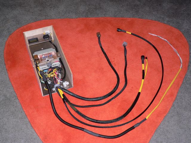
Posted by: TonyAKAVW Dec 16 2005, 03:04 AM
Closeup of the box. One of the important things I tried to do with the wiring was to isolate it mechanically. I'm using soldered connections so this is a must. We'll see how this works out long term, but with proper vibration isolation it ought to be okay.
Attached thumbnail(s)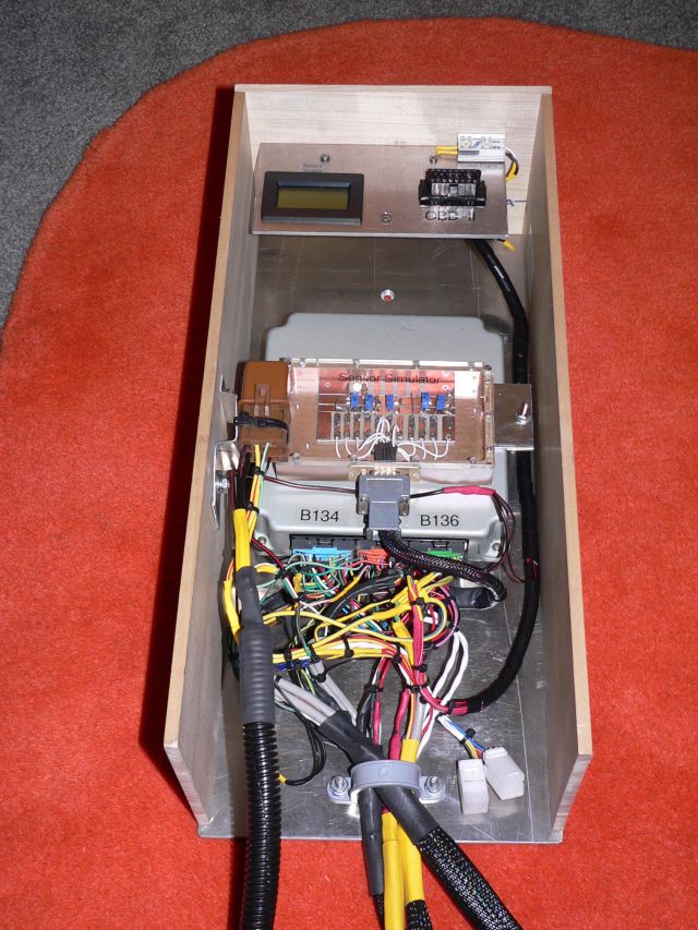
Posted by: TonyAKAVW Dec 16 2005, 03:06 AM
Diagnostics panel. The voltmeter is for battery voltage, but I may configure it so that it can be used to measure voltages with a set of probes. This would be a useful troubleshooting tool.
Attached image(s)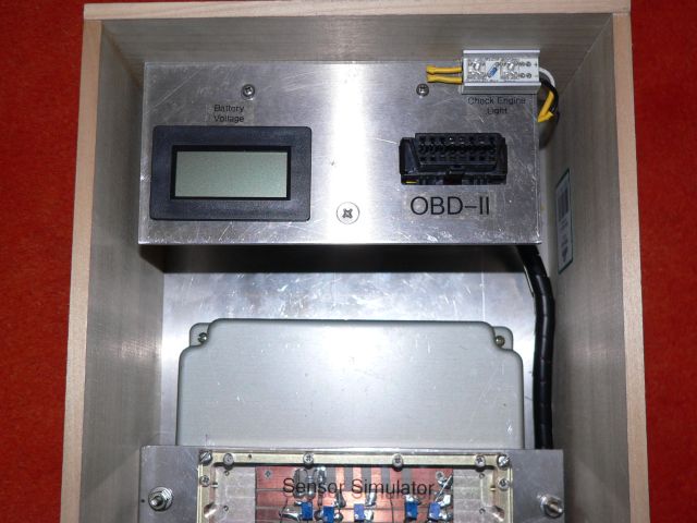
Posted by: TonyAKAVW Dec 16 2005, 03:16 AM
I mentioned that I would post schematics tonight, but my scanner isn't working... So tomorrow hopefully.
-Tony
Posted by: mrdezyne Dec 16 2005, 09:02 AM
Those schematics would be great since I am having a time sourcing manuals for a 2004 right now.
Posted by: TonyAKAVW Dec 16 2005, 11:43 AM
Okay, the manuals are available. One place is here:
techinfo.subaru.com You can download whatever you want in a 72 hour subscription for $34.95
Or...
Alldatadiy.com is a service that has service manuals online. I have a subscription for my wife's TT and its a great service. They ought to have full manuals for basically every car. I think its $25 or so a year, and $15 for each additional car.
I can't remember the place I got my manual. It was some web site that I found doing a search on google.
Chances are that the schematics for my engine and ECU are going to be very different from yours. I remember noticing that the ECUs and wiring diagrams for even one or two years off were significantly different. So when I post the schematics later today, remember that they may not be applicable, and it would be really easy to blow up an ECU or sensor if its not hooked up right. The schematics I'm going to put up are just a small fraction of the overall circuit. They are just for the power conenctions, fan relays, main relay, and fuel pump. Its the stuff in the manual that is a little harder to track down than the rest.
-Tony
Posted by: mrdezyne Dec 16 2005, 12:58 PM
Thanks,
I found the Alldata site yesterday but there was no way to check if they had my specific car until I subscribed. It looked pretty comprehensive from the samples provided however. Thanks again.
Curt
Posted by: TonyAKAVW Dec 18 2005, 03:51 AM
Well today I went to the local pick-n-pull and picked up a complete 1985 MR2 cable shifter setup. The only part I didn't bother to pull off was the fixture on the transmission. I'm planning on custom machining a bracket for the transmission to translate two cable pull/pushes into rotate and push/pull.
So I built a standoff for the new shifter. Since the lever is so much shorter, the whole shifter needed to be moved up 7 inches from the center tunnel. Luckily that happened to be above the level of my new center console ECU box. The cable shifter will make accessing the ECU a bit more tricky, but not too difficult.
The cables that came with the shifter are far too short for use in a 914, so I'm planning on ordering a set of cables from Mcmaster Carr. Damn things are like $70 each!
-Tony
Attached image(s)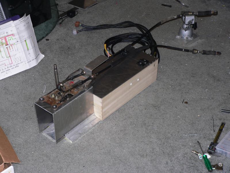
Posted by: Dr. Roger Dec 18 2005, 04:44 AM
Tony,
This has been a most impressive progress thread.
Thanks for all the pics too.
Keep up the great work.
Posted by: nsyr Dec 18 2005, 08:45 PM
http://www.autocds.ru/2004%20STI/
it says it is for the sti but it actually has the 2 liter turbo and n/a as well.
Posted by: nsyr Dec 18 2005, 08:47 PM
http://www.main.experiencetherave.com:8080/subaru_manual_scans/
has different years and models
Posted by: mrdezyne Dec 19 2005, 09:01 AM
| QUOTE (nsyr @ Dec 18 2005, 06:47 PM) |
| http://www.main.experiencetherave.com:8080/subaru_manual_scans/ has different years and models |
This one leads to-
"The 2004 STi FSM has been removed due to the amount of traffic and
the limited bandwidth. This manual can be found elsewhere on the net."
Just FYI,
But the first link is a gold mine! Thanks!
Posted by: TonyAKAVW Jan 23 2006, 01:17 AM
A couple people were asking me for dimensions of the engine support bar I made.
A word of caution. These dimensions are from a bar which doesn't quite fit exactly. Now it may be that the dimensions are fine, but I have a 1/2 inch gap on the passenger side fo the car, which I have to fix. Its probably jsut a amtter of getting the angles correct.
Angles between all pieces are 15 degrees.
This bar was made with 1.5 inch square steel tubing.
Plates are welded to the bottom edge for the actual engine mounts. I used 1/2 inch thick steel for those.
-TOny
Attached image(s)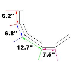
Posted by: TonyAKAVW Jan 23 2006, 01:19 AM
In another therad I talked about the idea of putting a flat bottom on the subaru conversion car and a diffusor at the back. This is not for sticking to the ground, but rather to create low pressure beneath the car for assisting in pulling air through the radiator at high speed.
Here are a couple drawings of what it might look like. Oh, I am also having my eshaust exit through holes in the bumper and a grated area around the license plate to exit the hot air beneath the trunk.
Attached image(s)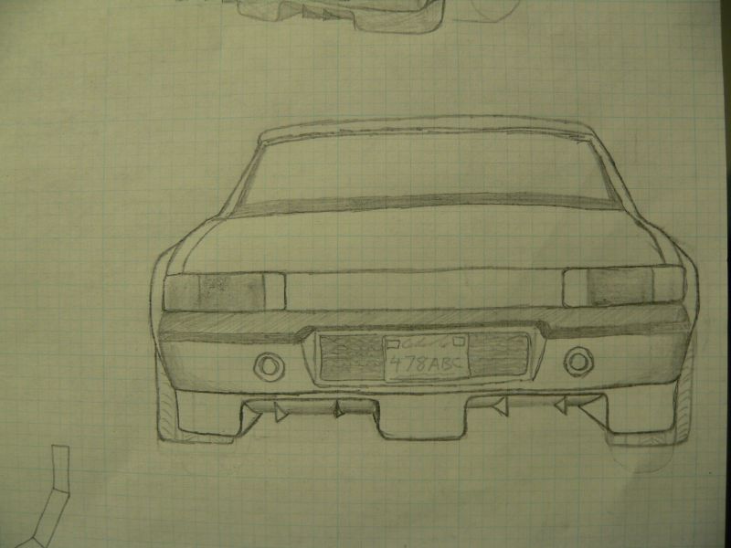
Posted by: TonyAKAVW Jan 23 2006, 01:20 AM
..
Attached image(s)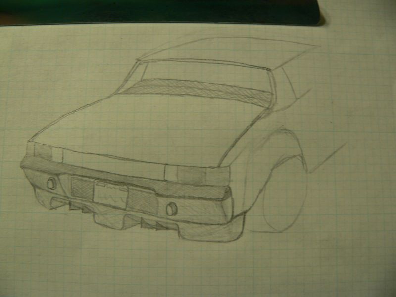
Posted by: Hydra Jan 23 2006, 05:28 AM
Tony, i find that diffuser idea pretty interesting, but from what i understand, you'll be getting the air to flow through the rad, and down under the car, right?
Do you have any sketches of what the diffuser will look like under the car, a bottom view that is?
Good luck on your converion, it's looking real good
Posted by: TonyAKAVW Jan 30 2006, 12:56 AM
I got some major stuff accomplished this weekend. Friday evening after work I drove up to Los Osos and spent the weekend at Bondo's place. I managed to get my oil pan modified! Bondo did 99% of the welding using his really nice Miller Mig welder. All the time though he kept saynig "Man I wish I had a tig."
The pan still needs a clean up and then powdercoating, which I should be able to get to this week. One thing remains to be done, and that is the shortening of the oil pickup tube. Without the engine, I couldn't determine a good length for the tube, so I'll have to do that locally.
The welds look solid, but if there are any little pinholes, the powdercoating (inside and out) should take care of it. I'm planning on putting it on fairly thick, so it should make a good seal, nto to mention look halfway decent.
Attached image(s)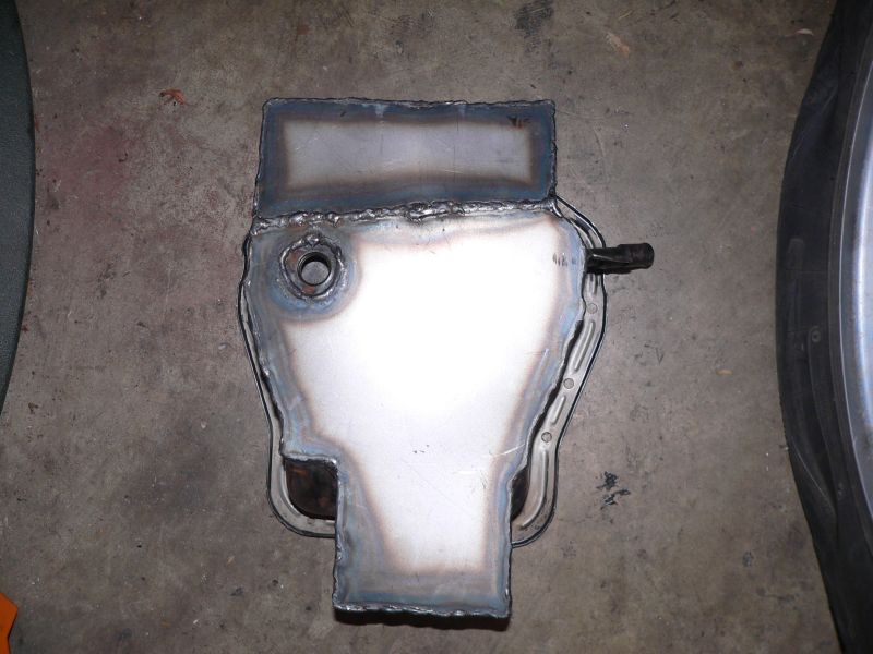
Posted by: TonyAKAVW Jan 30 2006, 12:57 AM
The extra volume might not quite bring it up to OEM capacity, but I'm sure its darn close.
Attached image(s)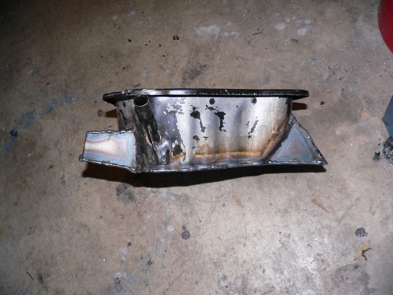
Posted by: TonyAKAVW Jan 30 2006, 01:02 AM
As if doing the oilpan wasn't enough, I also worked on the cable shifter setup. When I removed the shifter from an MR2, it came bolted to this stamped piece of metal that was probalby completely useable, especially for something which will eventually be hidden. So I replaced it with a 3/8 inch thick aluminum plate that I machined. Once I figure out how I'm going to mount it in the car, I will hog out more of the material to lighten it. The bracket on the rear (left hand side) will be the mounting point for the cables.
The third machined piece, on the right side is the lever that will replace the stock arm on the transmission. This is the arm that the linkage connects to normally. I am going to drill a bunch of holes in it for fine adjustability. This will allow me virtually any throw ratio on the shifter, from long to short.
Attached image(s)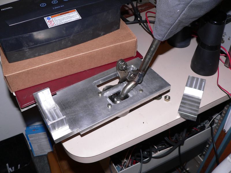
Posted by: TonyAKAVW Jan 30 2006, 01:03 AM
Lastly... Bondo gave me this cool red pushbutton switch. I'm planning on using this as my "all circuits on" switch. I'll have another pushbutton for the starter, but this will replace the first click on the ignition switch that turns on the main power to the car.
-Tony
Attached image(s)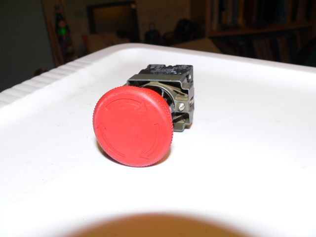
Posted by: MattR Jan 30 2006, 01:07 AM
| QUOTE (TonyAKAVW @ Jan 29 2006, 10:56 PM) |
| The welds look solid, but if there are any little pinholes, the powdercoating (inside and out) should take care of it. I'm planning on putting it on fairly thick, so it should make a good seal, nto to mention look halfway decent. |
Tony,
Looks good! But I would think about having the tank pressure tested and sealed. It doesnt cost too much and its really the right thing to do so you wont have any oil leaks from the tank IMO.
Posted by: Mueller Jan 30 2006, 01:36 AM
| QUOTE (MattR @ Jan 30 2006, 12:07 AM) | ||
Tony, Looks good! But I would think about having the tank pressure tested and sealed. It doesnt cost too much and its really the right thing to do so you wont have any oil leaks from the tank IMO. |
with a grease gun or hyd. bottle jack (w/gauge), he should be ale to build a hydro test fixtures pretty cheaply
Posted by: racerx7 Jan 30 2006, 01:40 AM
If you give me a place to upload, I have a 2002 FSM. I paid Subaru for a 24hr block of window to view
there pdf files. I spent all night/day down loading them. The downside is I just sorted them
by directories (engine, suspensions, etc..) Then there is like 50 files in each directory.
Posted by: Dr. Roger Jan 30 2006, 01:58 AM
you can put them here
ftp://www.grubbenterprises.com/incoming/
roger
Posted by: racerx7 Jan 30 2006, 02:11 AM
It says I do not have permission to upload.
Posted by: racerx7 Jan 30 2006, 02:32 AM
bump. are you still there? I would like to start this transer for you before I go to bed.
[00:19:39] 150 Opening ASCII mode data connection for /bin/ls.
[00:19:39] 628 bytes transferred. (10.2 KB/s) (60 ms)
[00:19:39] 226 Transfer complete.
[00:19:44] CWD /incoming
[00:19:44] 250 CWD command successful.
[00:19:44] PWD
[00:19:44] 257 "/incoming" is current directory.
[00:19:44] PASV
[00:19:44] 227 Entering Passive Mode (66,34,95,218,233,223)
[00:19:44] Opening data connection to 66.34.95.218 Port: 59871
[00:19:44] LIST -aL
[00:19:44] 150 Opening ASCII mode data connection for /bin/ls.
[00:19:44] 905 bytes transferred. (14.7 KB/s) (60 ms)
[00:19:44] 226 Transfer complete.
[00:20:33] MKD /incoming/Service Manuals
[00:20:34] 550 /incoming/Service Manuals: Permission denied on server. (Upload dirs)
[00:20:34] CWD /incoming/Service Manuals
[00:20:34] 550 /incoming/Service Manuals: No such file or directory.
[00:20:34] Transfer failed.
Posted by: Dr. Roger Jan 30 2006, 02:34 AM
| QUOTE (TonyAKAVW @ Jan 23 2006, 12:19 AM) |
| In another therad I talked about the idea of putting a flat bottom on the subaru conversion car and a diffusor at the back. This is not for sticking to the ground, but rather to create low pressure beneath the car for assisting in pulling air through the radiator at high speed. Here are a couple drawings of what it might look like. Oh, I am also having my eshaust exit through holes in the bumper and a grated area around the license plate to exit the hot air beneath the trunk. |
Now this is what I call a rear diffuser.

Posted by: racerx7 Jan 30 2006, 02:40 AM
I get it now. It will let me upload a single file but not directories:(
Posted by: Dr. Roger Jan 30 2006, 02:40 AM
| QUOTE (racerx7 @ Jan 30 2006, 01:32 AM) |
| bump. are you still there? I would like to start this transer for you before I go to bed. [00:19:39] 150 Opening ASCII mode data connection for /bin/ls. [00:19:39] 628 bytes transferred. (10.2 KB/s) (60 ms) [00:19:39] 226 Transfer complete. [00:19:44] CWD /incoming [00:19:44] 250 CWD command successful. [00:19:44] PWD [00:19:44] 257 "/incoming" is current directory. [00:19:44] PASV [00:19:44] 227 Entering Passive Mode (66,34,95,218,233,223) [00:19:44] Opening data connection to 66.34.95.218 Port: 59871 [00:19:44] LIST -aL [00:19:44] 150 Opening ASCII mode data connection for /bin/ls. [00:19:44] 905 bytes transferred. (14.7 KB/s) (60 ms) [00:19:44] 226 Transfer complete. [00:20:33] MKD /incoming/Service Manuals [00:20:34] 550 /incoming/Service Manuals: Permission denied on server. (Upload dirs) [00:20:34] CWD /incoming/Service Manuals [00:20:34] 550 /incoming/Service Manuals: No such file or directory. [00:20:34] Transfer failed. |
oh yea', you can't create dir's. only drop files....
note where it pooped out...
=-)
roger
Posted by: racerx7 Jan 30 2006, 02:42 AM
I need to be able to upload a 155 folders and 955 files 175mb.
Posted by: racerx7 Jan 30 2006, 02:45 AM
Is it your machine? Can you change the ftp server?
Never mind. I will try and zip it to one big file. You can just unzip when you want it.
Posted by: Dr. Roger Jan 30 2006, 02:45 AM
in all seriousness tony, i saw a jag prototype earlier today that had a great belly pan/rear diffuser combo that looked so bad-ass and i cant' find the link to it now.... grrrrrrrrrrrrrrr.
you know that setup would lower drag on our 914's big time...
keep up the great new designs. A+ on the exhaust dumping thru the bumper...
Posted by: racerx7 Jan 30 2006, 03:03 AM
Uploaded started. File is called manual.zip
Posted by: speedster356 Feb 2 2006, 01:56 AM
Re: the rear radiator setup. I have a 550 Spyder replica with the same setup (picking up air from the belly pan). I'm running non standard EJ20T turbo engine, 16psi boost with 8.5:1 comp. Mild tune gives me 248 HP at the rear wheels. I've found that the current config will not handle long on boost laps and gets to very high temps very quickly. The first setup had only approx a 70 mm gap in the pan for pickup the full width of the radiator (standrd WRX 21mm thk single row 770mm x 500mm I think).
Results were: on the track
(1) 70mm slot only, no scoop, standard 2 speed fans running on high 100%.........................overheating
(2) 50mm deflector plate along bottom of radiator and into airflow and fans..........................overheating
(3) cut out the firewall and have two 300 x 300 holes in belly pan in front of the radiator with composite ducting, fans ............................................................................................................................didn't overheat
until well heat soaked after more laps, then overheated.
(4) 700mm wide scoop with a 40 mm mouth opening from light weight aluminium sheet.........best resistence to overheating but lasted one touch of the ripple strip!
(5) spring loaded scoop, as suggested above it needs to be tensioned , ....................................started to osolate at 130MPH and self destructed.
(6) last week failed #4 forged piston due high temp.
(7) yesterday started to fab front mounted radiator.
Your engine won't be generating as much heat so you will most likely be OK with the setup. There are a few guys here running japanese engines in VWs and the NA cars have run radiators slanted above the gearbox with no problems.
Have fun
Posted by: TonyAKAVW Feb 2 2006, 12:01 PM
Thats some really good information! What sort of ground clearance does your car have? I'm curious what sort of airflow you actually get under your car.
Also, how do you exhaust the heated air?
My current plan is not to take air from under the car, but instead from above. I will have some kind of subtle scoop integrated into the trailing edge of the roof line. To exhaust the heated air I am going to suck it out the bottom of the car by means of accelerated air flow created by a flat bottom and rear diffusor. Thats the theory at least
I really want to develop something for the engine bay that can handle more than just a naturally aspirated EJ25. Someday I may want to put in a turbo motor.
-Tony
Posted by: TonyAKAVW Feb 2 2006, 12:36 PM
Here's the basic idea... I have no idea if it will work
Attached thumbnail(s)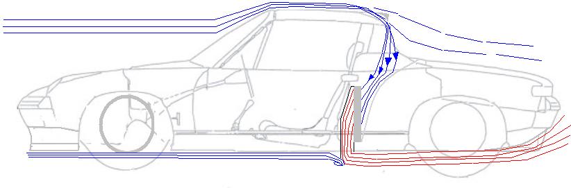
Posted by: d914 Feb 2 2006, 12:39 PM
well hurry then, my plan is for a turbo, and I don't have to be subtle with the scoop.... How about a reverse scoop like the suby hood scoop turned 180???
Posted by: tat2dphreak Feb 2 2006, 01:17 PM
IIRC the porscheru had a scoop hanging down below the car to grab more air for the radiator... also, why not vent the front firewall and use the heat tubes to carry more air back...
Posted by: speedster356 Feb 2 2006, 02:33 PM
I had quite a good air flow under the car but still a low pressure area. The cars sitting with about 80mm clearance between road and belly pan, much less under heavy braking, I think with the bigger scoop it would have been no problem for cooling. Air exit was just via the engine area in the rear, very turbulant area so not the best exit conditions. The 2 grills at the back were used for intercooler air exit. The intercooler picked up ducted air from just inside the rear wheels, in this position (above the gearbox) it was open to heat sink problems in the engine compartment . The new setup will have the interccoler mounted in the old radiator position (in the front of the engine) as I don't think it's as critical for air delivery as the radiator, all headers the turbo and exhausts ceramic coated, 2.5 STI block with 2.0l heads etc. detuned to 260 HP at the rear wheels on low boost ( not the crazy 330+ they get here with these engines). This should give me a low stress engine and the best conditions for cooling.
I like your idea of a roof scoop, air delivery was one of the hardest things I found on my car as I didn't want to have big cutouts on the topside of the body so as to retain the original look of the car. Nothing better than smoking a thumping V8 at the drags in an "old timer car"......
Posted by: TonyAKAVW Feb 5 2006, 11:59 PM
So I neded up doing a water test of the oil pan. I filled the pan with soapy water and let it sit for a few hours. The pan ended up having two small pinholes, which I fixed by filling them with braze. I bought a MAAP Gas torch and brazing rod at the hardware store which worked well. The leaks are gone and so yesterday I did some serious powder coating.
The oilpan will probably need some more powder, as I couldn't get full coverage inside. If I can't get powder to work I'll slosh around some POR-15. The bottom of the pan on the outside ended up a little thin on the powder so I'll add some more and re-bake.
The engine bar came out perfectly, and I drilled holes through the almunim blocks to finish it up. The inside of the bar still needs some POR-15 and a drain hole at the bottom, but otherwise its done.
-Tony
Attached image(s)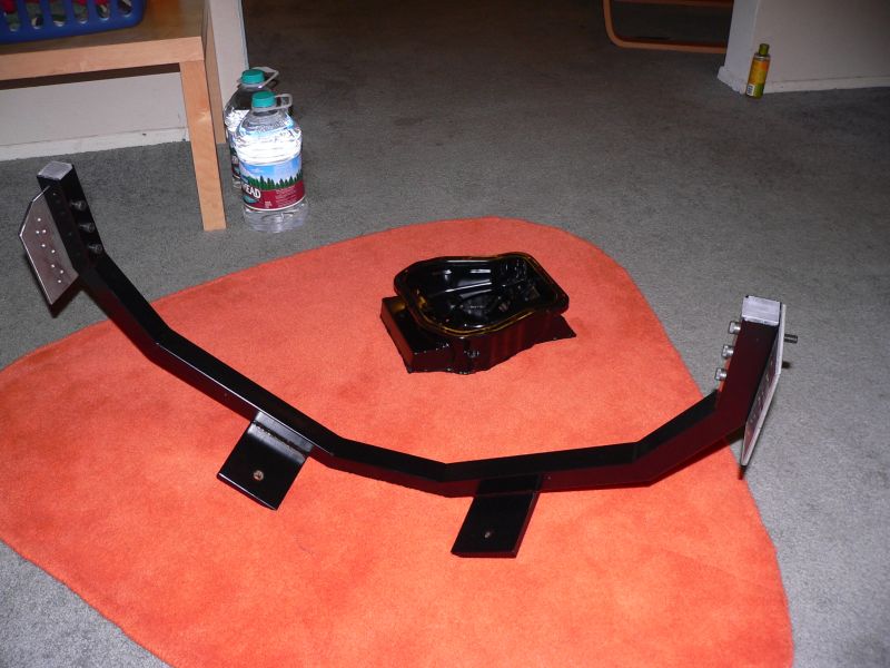
Posted by: TonyAKAVW Feb 6 2006, 12:00 AM
..
Attached image(s)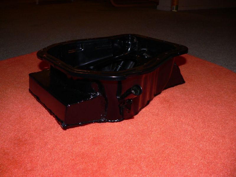
Posted by: TonyAKAVW Feb 6 2006, 12:00 AM
...
Attached image(s)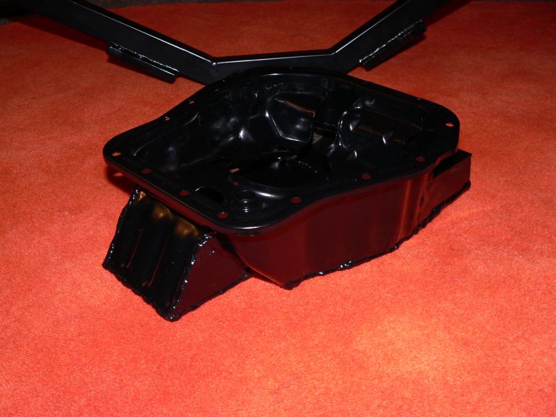
Posted by: TonyAKAVW Feb 6 2006, 12:01 AM
Those are 3/8 inch diameter bolts.
The bare steel plate get welded to the longitudinals near the trunk firewall.
Attached image(s)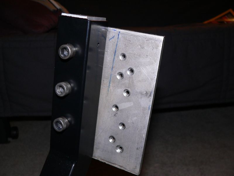
Posted by: Crazyhippy Feb 6 2006, 09:25 AM
There's a decent diffuser thread on the Subbie board..
http://forums.nasioc.com/forums/showthread.php?t=915274
BJH
Posted by: bondo Feb 6 2006, 01:35 PM
Man, I wish I had a tig.
Posted by: turbo914v8 Feb 6 2006, 03:13 PM
I have a Tig.
Man I whish I know how to use the Tig.
Posted by: Crazyhippy Feb 6 2006, 07:36 PM
Learning tig wasn't too tough for me. If you know how to Oxy Acetalene weld, it's very similar.
Find somone local and have them give you a crash course.
Posted by: TonyAKAVW Feb 10 2006, 02:51 AM
Got some work done tongiht on the engine. I'm starting to get it all put back together. I put the intake manifold and throttle body on, as well as the injectors and runners. Also, the water pipe that conencts one side of the engine to the other. The oil tank is on, as well as the shortened pickup tube. I managed to tighten all the bolts around the perimeter of the oilpan. This was based on a lesson learned from Scott's oilpan where he ran into problems getting a few of the bolts tightened. I put some effort into designing my oil tank mods such that the bolts were accesible, at least by some means...
The pulley on the front needs torqueing down but after that I can install my custom alternator bracket, and the alternator.
Anyway, here's the modified pickup tube. I basically cut out something like 1.5 inches of the tube and brazed it back together. Across the bottom of the pickup tube, Bondo welded a piece of welding rod. This is an idea I stole from Outback Motors. They do this so that if the pan gets bashed in, something keeps the intake opening somewhat clear.
Attached image(s)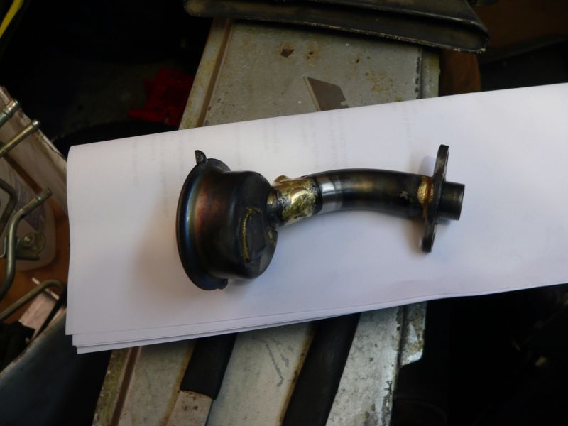
Posted by: TonyAKAVW Feb 10 2006, 02:51 AM
The engine is finally starting to look like an engine!
Attached image(s)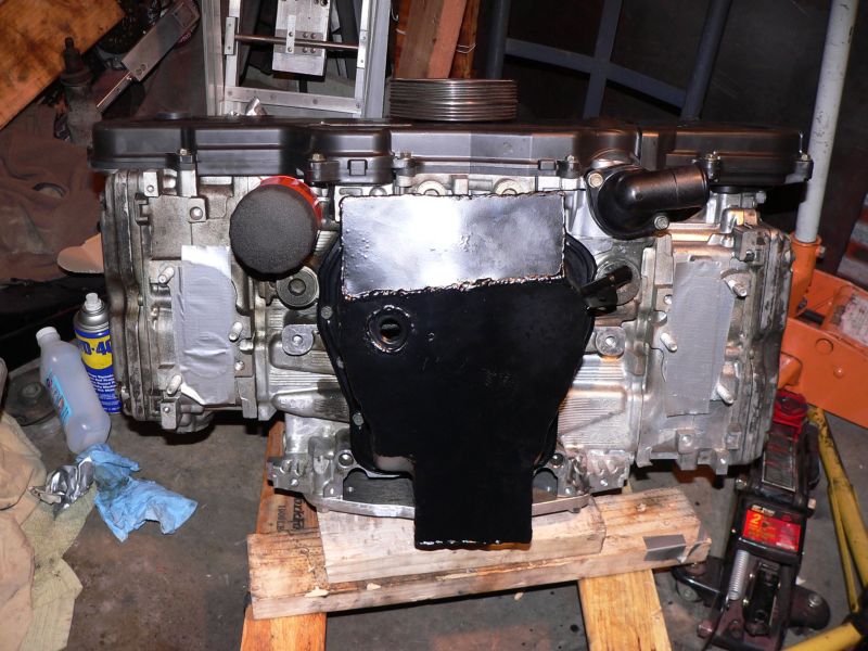
Posted by: TonyAKAVW Feb 10 2006, 02:52 AM
more engine stuff.
Attached image(s)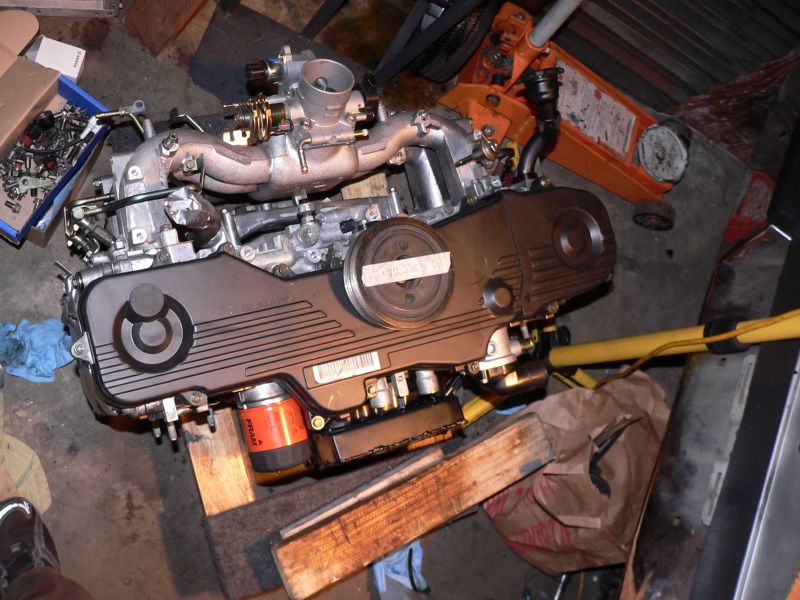
Posted by: TonyAKAVW Feb 13 2006, 01:07 AM
Got the intake installed. The intake is an AEM intake. I cut one of the tubes shorter than normal, and had to build a bracket to hold it up. Bracket is made of aluminum and steel, and powdercoated. Between the rbacket and the intake tube is a small piece of silicone rubber.
-Tony
Attached image(s)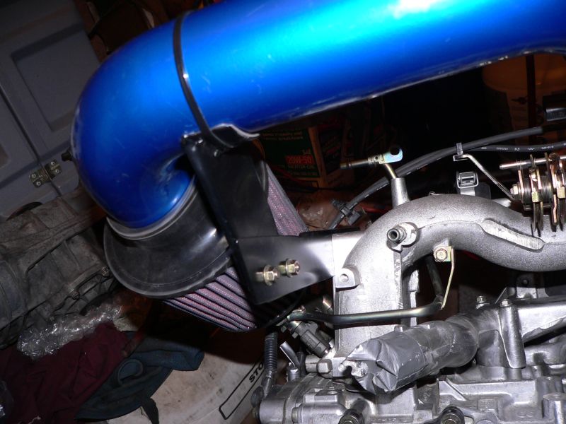
Posted by: TonyAKAVW Feb 13 2006, 01:09 AM
Engine is almost done. Left to do:
Bolt on the alternator, bracket, and belt
Fuel and air hoses
Install/adjust engine wiring harness.
-Tony
Attached image(s)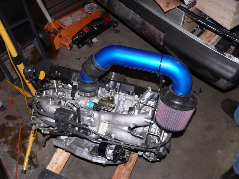
Posted by: mrdezyne Feb 13 2006, 09:23 AM
Looks familiar.... Keep up the great work!
Posted by: TonyAKAVW Mar 5 2006, 11:55 PM
Well, the engine is now basically ready for installation. The only things left are to bolt on the flywheel and fuel injection hose. Otherwise its all wired up, all the vacuum lines and sensors are installed, etc.

-Tony
Posted by: TonyAKAVW Mar 5 2006, 11:58 PM
This weekend I started working on the cable shifter, the portion that botls to the shifter console on the transmission that is.
I made ample use of my Sherline lathe, hacksaw, drill press, taps, and files. I'm not sure if its clear (probably is to some, not to others) how this whole thing will work.
Basically the threaded rods will connect to the cables and provide the two degrees of motion needed to select a gear.
I still have a bit of work left on this, but the major components are under way.
-Tony


Posted by: Dr. Roger Mar 6 2006, 12:03 AM
tony, im' sure you mentined before but what is the peak torque/HP and max RPM on this beast?
Posted by: TonyAKAVW Mar 6 2006, 12:34 AM
| QUOTE |
| what is the peak torque/HP and max RPM on this beast? |
On the first page of this thread is a dyno run plot of an EJ25 engine. It looks like the peak torque is 163 ft lbs and peak horsepower is 165 or so.
I will be running this with no cat and a better air intake, no air conditioner or power steering pump, so I figure I'll be at 170 - 175 HP.
-Tony
Posted by: bondo Mar 6 2006, 12:39 AM
What are you doing to compensate for the thickness of the plate?
Posted by: TonyAKAVW Mar 6 2006, 12:44 AM
| QUOTE |
| What are you doing to compensate for the thickness of the plate? |
Well, I'm actually going to cut away the plate so that the bit that goes on the end of the shift rod can go down as far as it needs to go. So the plate thickness won't matter at that point.
-Tony
Posted by: TonyAKAVW Apr 7 2006, 09:12 PM
First bit of progress in a month!
The silver roller is now out of the garage, so tomorrow I'm pulling the 1.7 out of the daily driver and getting it ready for the Subaru conversion.
So if anyone wants a 1.7, let me know.
Hopefully next weekend I an install the Subaru engine
-Tony
Posted by: vespasoul Apr 10 2006, 02:39 AM
why go through so much hassel? when renegade hybrids has already perfected the subie conversion
http://renegadehybrids.com/914/shortdonutcompressed.avi
Posted by: redshift Apr 10 2006, 02:48 AM
Because he rocks, and he thought of it first.
Great work, Tony! Looking good!
M
Posted by: Dr Evil Apr 10 2006, 07:34 AM
| QUOTE (vespasoul @ Apr 10 2006, 04:39 AM) |
| why go through so much hassel? when renegade hybrids has already perfected the subie conversion http://renegadehybrids.com/914/shortdonutcompressed.avi |
Designing your own set up, documenting it, and being a pioneer are all worth more than a conversion in the box. Probably even cost less.
Short answer: Same reason a dog licks himslef
Posted by: TonyAKAVW May 9 2006, 03:23 AM
Finally some progress to report. For those just re-tuning in, I have abandoned the silver car conversion and am in the process of converting my yellow '70 1.7 to an EJ25.
A month ago or so, I had an engine pull party. In the time since then, I have stripped out all unneeded metal in the engine bay (except the OEM engine mounts, which are both difficult to remove and might prove useful in the future). Additionally, I have ground down the remaining spot welds, filled in a few overzealous grinds, etc. I've spent quite a few hours sanding everything smooth. While it doesn't LOOK nice it is for the most part nice and smooth. Its not perfect, but it is good enough for me. With some luck I will be able to get the Zero Rust sprayed in this coming Saturday.
-Tony
Attached image(s)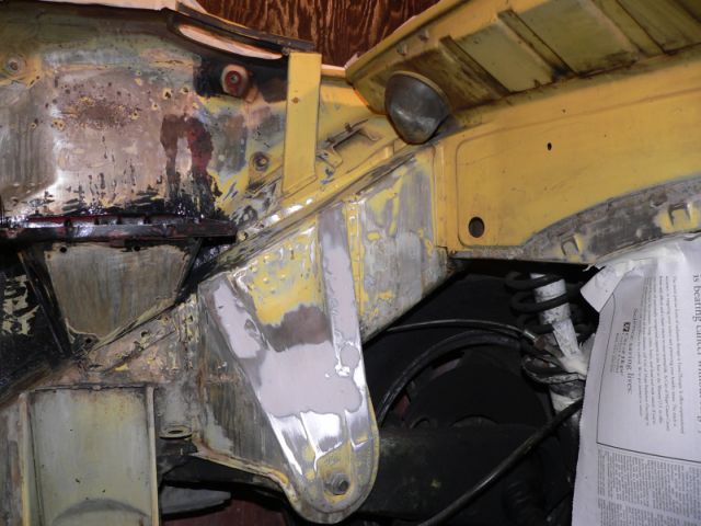
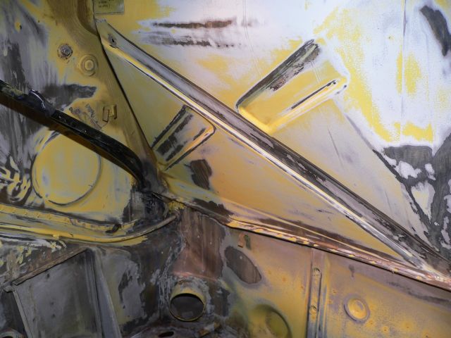
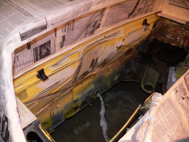
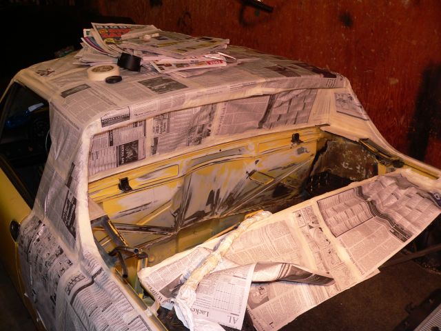
Posted by: mrdezyne May 9 2006, 08:40 AM
WOW! Very nice fire wall to start with! I could only dream of having a clean rust free engine bay to work from. One day soon it will be back in shape but you have a great head start! Can't wait to see what happens next. Keep up the great work, I'm following along with every step as are many others...
Posted by: fiid May 9 2006, 09:55 AM
There were a bunch of conversions already in progress when renegade started. Them being a full service shop with budget and full-time employees meant they finished first, and they did do a very nice job, but the other conversions that are in progress are all interesting for different reasons. In this case, the oil pan modifications and the ability to run the radiator in the engine compartment are of particular interest - especially given what an amazingly clean job Tony is doing.

why go through so much hassel? when renegade hybrids has already perfected the subie conversion
http://renegadehybrids.com/914/shortdonutcompressed.avi
Posted by: fiid May 9 2006, 09:58 AM
Tony - is that a cable shift modification to the 901 sideshifter??
Schweet - nice work!!
Posted by: jsteele22 May 9 2006, 10:07 AM
Wow, cleaning up the engine bay looks like a real PITA, and a thankless job at that. It'll be nice to see it w/ some paint (and an engine).
BTW, now that history is being written, Scott Thatcher had his EJ25 swap, with radiator in the engine bay, on the road (cross country and back ) before Renegade announced their kit.
Posted by: TonyAKAVW May 9 2006, 11:02 AM
Thanks for all the comments.
Fiid: Yes, that's the beginning of a 901 cable shifter cconversion. I've decided that I need to build the part that goes onto the transmission much stronger, so that prototype will just be for getting the dimensions right. I need to borrow some time on a milling machine to make a suitably strong cable adapter.
jsteele22: The engine bay SUCKS to prep for paint. Its a maze of tight corners, bad painting by the factory (I sanded down several runs, there were lots of little holes in the final paint too) and lots of seam sealant that cracks and traps water.
Painting it should be similarly difficult, so I need to get some practice in before I do the job.
I've already addressed much earlier on in this thread why I've chosen not to use a Renegade setup. Kind of like why people climb mountains. "Because its there."
-Tony
Posted by: TonyAKAVW May 17 2006, 10:58 AM
This progress was posted at Pelican parts during the Great 914Club Hacker Blackout. I'm posting them here to keep the thread as a record of the work.
Attached image(s)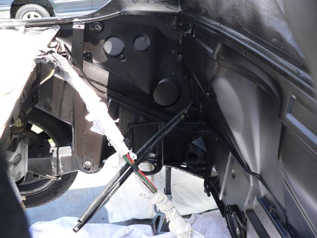
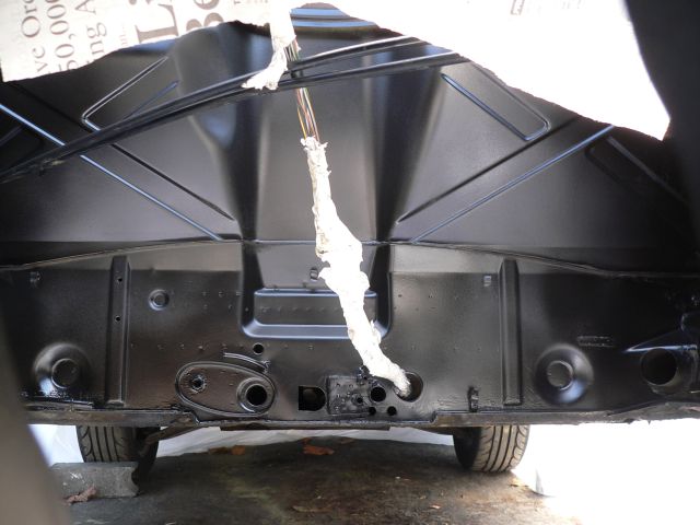
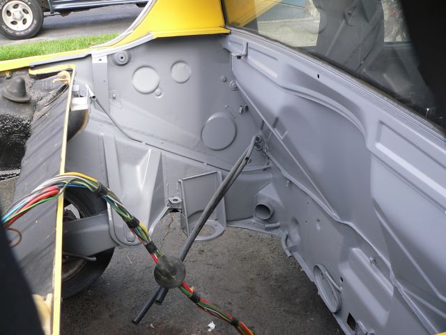
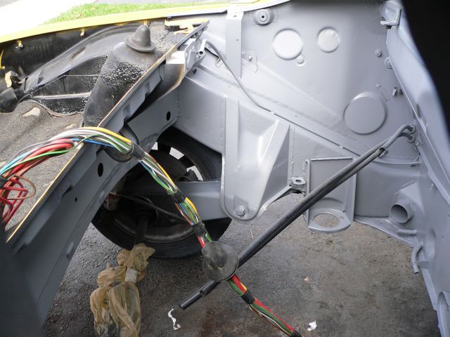
Posted by: TonyAKAVW May 29 2006, 01:56 AM
Stuff is now starting to get put into the engine bay. So far I haev put the battery back in, installed the new junction box, put back the brake proportioning valve, and brand new rigid rear brake lines. Also reconnected the parking brake tubes. The radiator frame is the next item to install. I am now thinking that I want to put some kind of rubber sheet or some sort of protection against the firewall to prevent it from being damaged by a continual spray of water laden hot air.
-Tony
Attached image(s)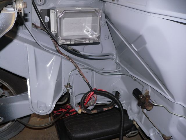
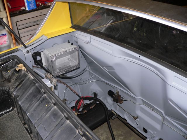
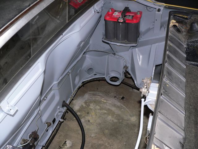
Posted by: redshift May 29 2006, 04:10 AM
WOW!I am going to have the most worthless teener in all creation! FANTASTIC LOOKING WORK TONY!
M!
Posted by: John G May 29 2006, 11:18 AM
Tony,
When I was looking at Jake Raby's car, he mentioned that he sprayed the entire engine compartment with Line-X; one of those pickup bedliner products. I'm not sure how heat resistant that stuff is, but that might be a solution for your firewall.
Your engine bay looks PRISTINE. Great work!
John
Posted by: jimkelly May 29 2006, 06:02 PM
http://forums.pelicanparts.com/showthread.php?threadid=282646
Posted by: TonyAKAVW May 29 2006, 10:14 PM
More progress! Today I installed the radiator frame, made a shroud to cover the cable outlets, and put the radiator in.
Attached image(s)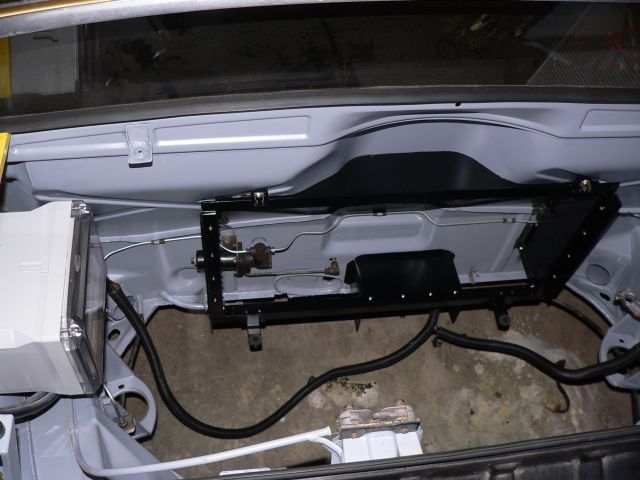
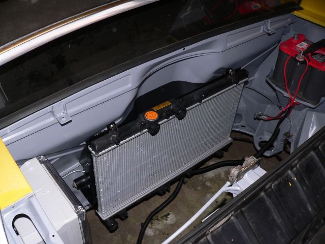
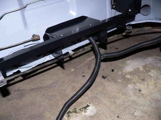
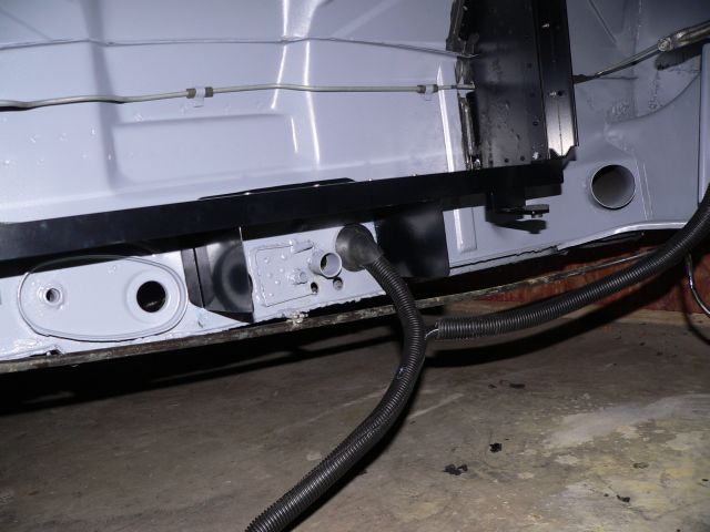
Posted by: TonyAKAVW May 29 2006, 10:15 PM
,,
Attached image(s)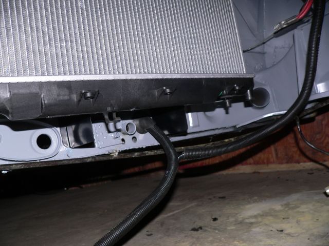
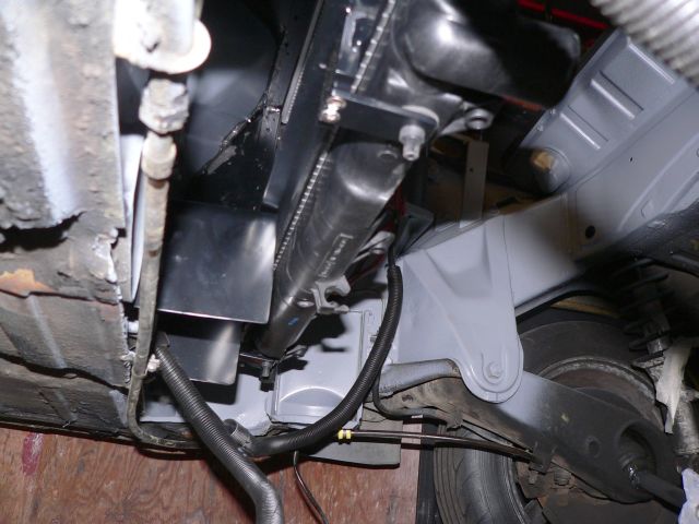
Posted by: KaptKaos May 29 2006, 10:24 PM
Looks awesome Tony!
Whats the schedule for the rest?
Posted by: TonyAKAVW May 29 2006, 10:34 PM
Well, I've got a number of things in the works right now. The one thing that will definitely take some time is that I need to order a new flywheel from KEP and apparently there is a 5 week lead time on that part. In the meantime though I need to finish wiring, install the ECU, and get some serious work done on my cable shifter. So at least two months until its ready to roll.
-Tony
Posted by: Aaron Cox May 29 2006, 10:36 PM
looks so foreign... with a radiator in the engine bay...
this aint no front engine "i get air flow" car....
looks sick. hope your cooling works 
Posted by: KaptKaos May 29 2006, 10:41 PM
Well, I've got a number of things in the works right now. The one thing that will definitely take some time is that I need to order a new flywheel from KEP and apparently there is a 5 week lead time on that part. In the meantime though I need to finish wiring, install the ECU, and get some serious work done on my cable shifter. So at least two months until its ready to roll.
-Tony
Bummer on that lead time.
Just let me know when you need a hand.
Posted by: redshift May 30 2006, 06:35 AM
Damn TONY! Your work is METICULOUS! WHAT A BLOWOUT! UNREAL!
I am.. I just can't believe it!
M
Posted by: jimkelly Jun 1 2006, 04:18 PM
Looks like the lower bracket/shifter box blocks about 33% of the potential inbound air flow? Any thoughts of cutting in some holes at the top? Ditto on the beautiful job and progress : )
Posted by: TonyAKAVW Jun 1 2006, 04:59 PM
The aperature blockage is actually the exhaust aperature. This cooling system will operate from the top down. That is, I will have a small spoiler just past the trailing edge of the roof line which upon positioning into the airstream will divert lots of air down into the engine bay. Instead of the usual engine lid grill I am going to use a series of vanes to aid in directing the air down. These vanes will extend up into the area that is normally solid. In the end it will be a super-GT-style engine bay lid.
The spoiler will attach to the car using the bolt holes for a ski rack. I still haven't quite figured out the details of it, but at some speed it will rise up into the air stream and push air into the engine bay.
As a further aide, I'm going to enclose the bottom of the car with a huge fiberglass sheet that will have an opening for the radiator exhaust, and a pair of venturi tunnels. By transitioning from a zone of high pressure (at the radiator exhaust) to a zone of low pressure (right behind the car) by means of an expanding tunnel, I ought to get a pretty decent pressure decrease under the car (in theory). Ideally this will benefit cooling by sucking air through the radiator, and at high speed may help to decrease lift.
-Tony
Attached image(s)
Posted by: Headrage Jun 1 2006, 05:28 PM
looks so foreign... with a radiator in the engine bay...
 Can't wait to see it on the PV peninsula.
Posted by: Dr Evil Jun 1 2006, 06:32 PM
Air flow proof 
Attached image(s)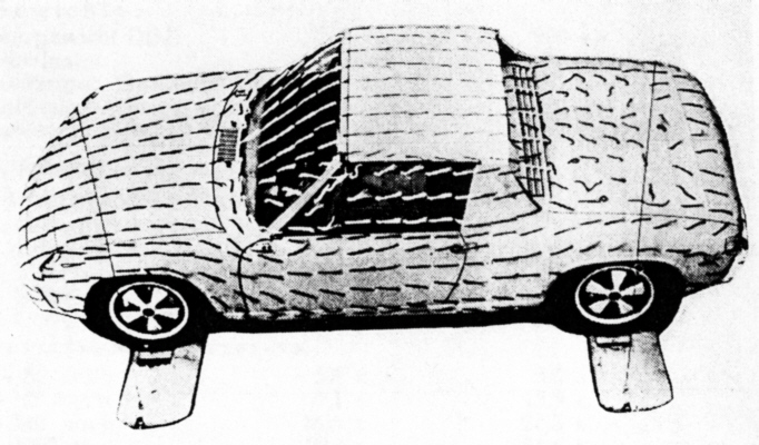
Posted by: Jes Jun 4 2006, 02:41 AM
TONY'S NEW HOME

J
Attached image(s)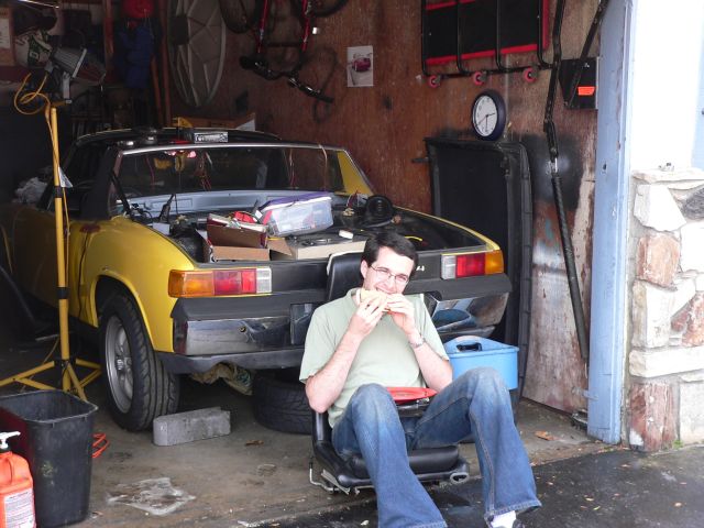
Posted by: banksyinoz Jun 4 2006, 04:01 AM
great lookin work tony hope to see video of the end result as i wll never see the car in the flesh

Posted by: TonyAKAVW Jun 11 2006, 11:05 PM
Got a few things done over the last week or two.
* Put carpet on the inside of the firewall. Doesn't look concourse, but its decent enough for me.
* Took the Subaru ECU out of that silly wooden box from several pages back. Not sure exactly what I'll do in the end, but for now I am using a plate of aluminum with rubber vibration dampeners mounted to the center tunnel. Still working on this...
* Ordered and took delivery of stainless steel lines for fuel. I bought 6 foot lengths of stainless tubing from Mcmaster Carr. Less than $20 for the two pieces and they come delivered in a cool packaging tube, useful for who knows.
* Began installation of said fuel lines. Instead of Clay's method of using a die to thread the tubing, I made a beading tool. Basically I took a vice grip and ground down the tip as show in pictures below. it works pretty well, though I might make it differently if I did it again. The bead is not as high as I would like but I think its sufficient.
* Made and installed a mount for the fuel pump and mounted the pump. I took a sheet of 1/8" aluminum plate and cut it to fit the engine mount. Used a couple Mcmaster Carr rubber isolation mounts and powder coated the whole thing. The gray doesn't match particularly well to the engine bay, but whatever.
So thats about it. I'm guessing by the end of this week i'll have the gas tank back in, connected up to the new fuel lines, and have the lines held in place with some kind of bracket, etc.
Note: cheapo tubing benders have a hard time with this tubing. Mine got bent out of shape bending the 3/8" stuff.
-Tony
Attached image(s)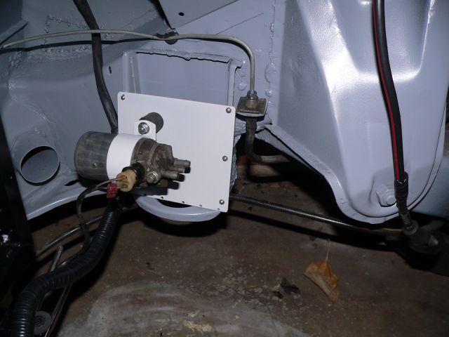
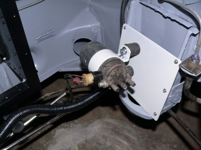
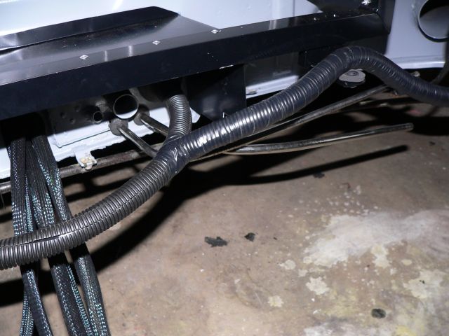
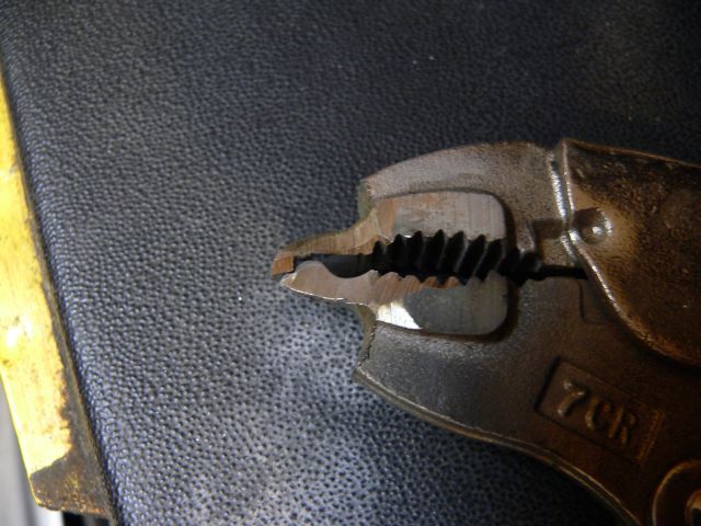
Posted by: TonyAKAVW Jun 11 2006, 11:06 PM
the rest...
Attached thumbnail(s)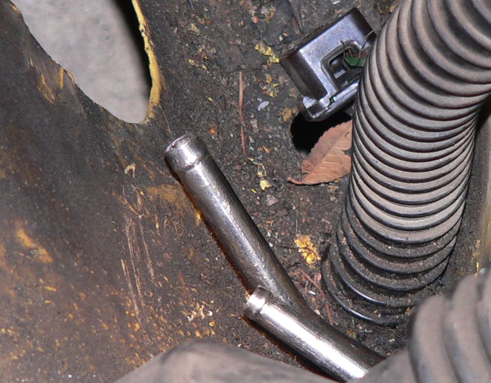
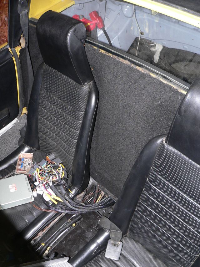
Posted by: fat73 Jun 12 2006, 12:21 AM
Hey Tony...
I'm in the middle (nearing the end) of a 914/WRX conversion myself. I'm considering changing the old fuel lines to steel lines, mainly because to make the WRX run it needs both the main fuel line and return line to feed the 928 fuel pump. A separate return line is required.. Sooooo,,,,I'm considering bypassing the existing lines in the center tunnel, teeing the two lines at the tank to 1/2" and running a 1/2" SS line back and a 5/16" return.
The lines you ordered, were they stainless? The only ones I can find on the Mcmaster Carr site that are 6' are ~ $70. The steel ones are inexpensive, but stainless is $$$. Can you give me the specs on your lines? Sure would appreciate that.
AND by the way....your work is amazing. Shows real imagination, engineering expertise, and GOBS of patience. I have really enjoyed keeping up with your progress. I took the easy way out (if there is such a thing) and bought everything Renegade had. Had my harness done at smallcar. Did all the welding/repair/stiffening/paint/rewiring/rebuilding myself. Nothing is easy when you take one of these cars COMPLETELY apart. I basically gutted my car and started with the shell. I told my helper (my daughter's boyfriend Mike) the other day, we must be putting this car back together now because we can't possibly take anything else off.
Anyway, any info you can provide on the tubing would be mavelous.
see community.webshots.com/user/fat73
Thanks a bunch.. Ed
Posted by: TonyAKAVW Jun 12 2006, 10:42 AM
fat73: Sounds like a nice conversion you have going!
Here are the part numbers for the stainless steel tubing...
8989K48 Type 304 Stainless Steel Welded Tubing 3/8" Od, .319" Id, .028" Wall, 6' Length $8.45 each
8989K46 Type 304 Stainless Steel Welded Tubing 5/16" Od, .257" Id, .028" Wall, 6' Length $7.63 each
Also, the vice grips I got for free. A few years ago, ACE hardware had a deal where you could get free vice grips with rebate. So i got 6 of them
-Tony
Posted by: TonyAKAVW Jun 21 2006, 01:11 AM
More progress to report.
Gas tank is back in, fuel lines are connected, fuel pump is conencted, ECU is mounted, shifter work progressing.
After finishing the stainless steel tubing installation, I put the gas tank back in, reconected everything including the pump in its new location. It sits below the battery tray, on the old engine mount.
The ECU is now mounted in the car. It is strapped to a 1/8 inch aluminum plate which I cut to fit between the seats. The plate is held onto the car with rubber isolation mounts, much like those used for the fuel pump. The ECU is then strapped to the plate using a compression strap I bought on the way home from work today at REI. The ECU sits on top of a 1/2 inch thick piece of foam rubber which I cut from a "sitting pad" that I also got at REI. On top of the ECU is the sensor simulator box. Sandwiched between the two is a piece of special silicone rubber made for reducing vibration on the inside of submarine bulkheads. (its really amazing what you can get shipped to you as free samples from companies).
So the ECU is now as safe as can be from vibration
Wiring to the ECU comes in through an enlarged hole to the center tunnel. The cables are then held in place with insulated wire tie-downs. Still left to do is mount the volt meter/OBDII conenctor plate, but that can wait.
The shifter should be bolted down to the center tunnel soon. As usual I used a lot of aluminum and screws to make the pedestal for the shifter.
-Tony
Attached thumbnail(s)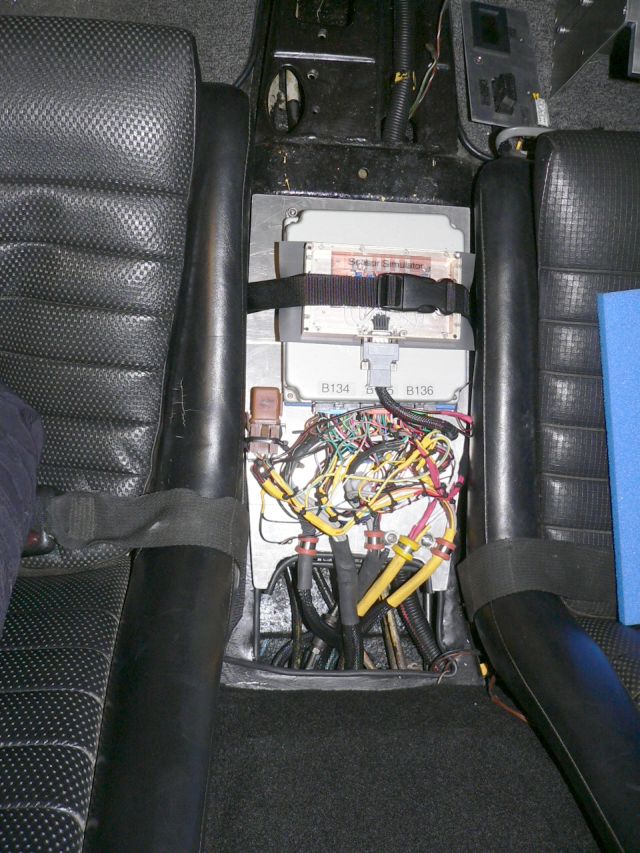
Attached image(s)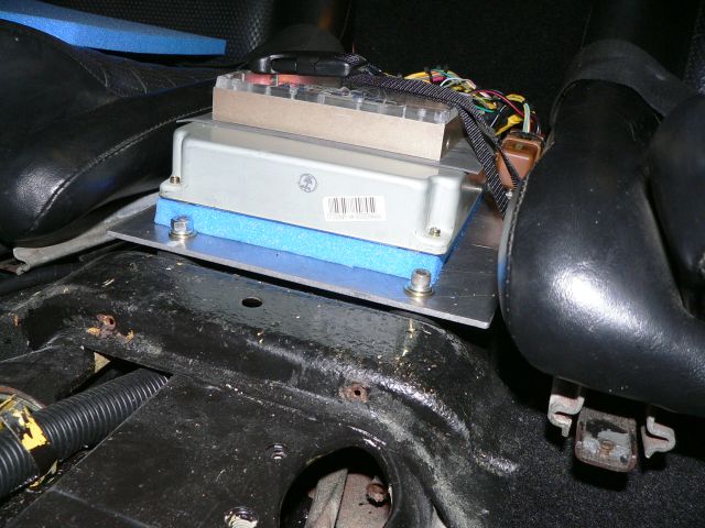
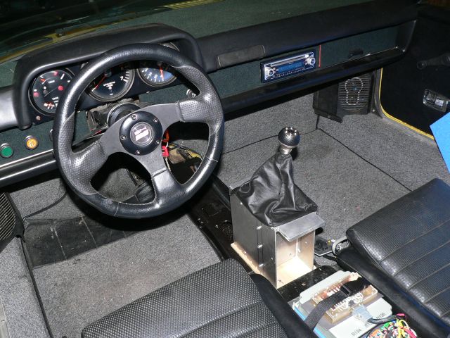
Posted by: TonyAKAVW Jun 21 2006, 01:12 AM
last one
Attached thumbnail(s)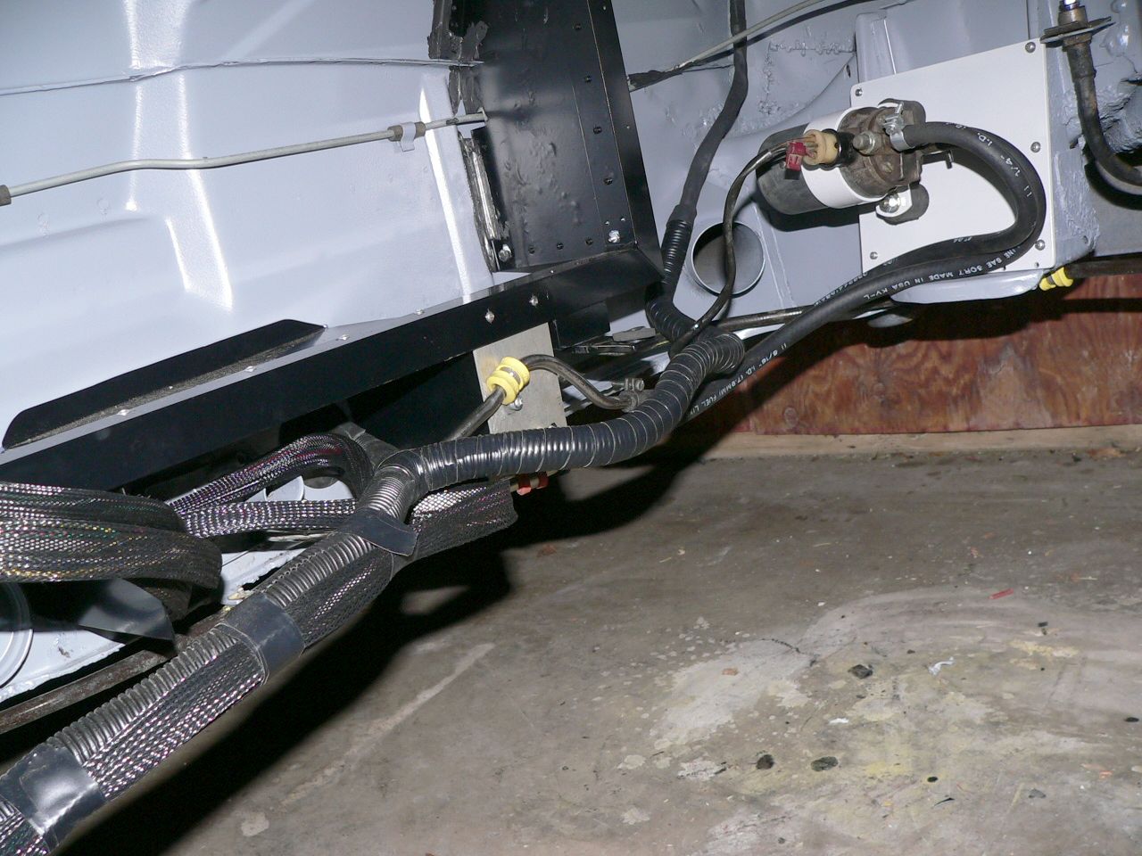
Posted by: Lou W Jun 21 2006, 05:47 AM
Tony, You're doing an awsome job, that engine compartment turned out real nice. 
Posted by: TonyAKAVW Jul 17 2006, 06:14 PM
Updates coming soon...
Today I received a new Tach (Autometer), a coolant resevoir, and radiator fans. Saturday I picked up CV bolts, pins, grease, throttle cable, and 911 sport mounts for the transmission.
I also placed an order for the exhaust primary tubes and gaskets from Outback Motors.
Also have an order into Kennedy Engineered Products for a flywheel, clutch kit, bolts, etc. 2-3 weeks lead time quoted on the flywheel.
Pretty much the last few things left to figure out are:
Exhaust - how to route tubing around, where exactly to mount mufflers.
Shifter - Need to finish machining the transmission end of things, and get push/pull cables
VSS - Probably going to make my own speed sensor using a hall sensor. not sure what to use as the rotating part though.
-Tony
Posted by: neo914-6 Jul 17 2006, 07:34 PM
That is CLEAN work Tony!
Have you fired up the engine?
Posted by: Brad Roberts Jul 17 2006, 07:45 PM
KEP always uses the 2-3 weeks shipping moto. It normally arrives within 5days.
B
Posted by: TonyAKAVW Jul 18 2006, 01:25 AM
First project this weekend while I was waiting for parts was to recover a door panel. The panel was in bad shape so I bought some new board and cut it out using the old one as a template. Took quite a while to get the board nicely cut out, but it came out decently.
Attached image(s)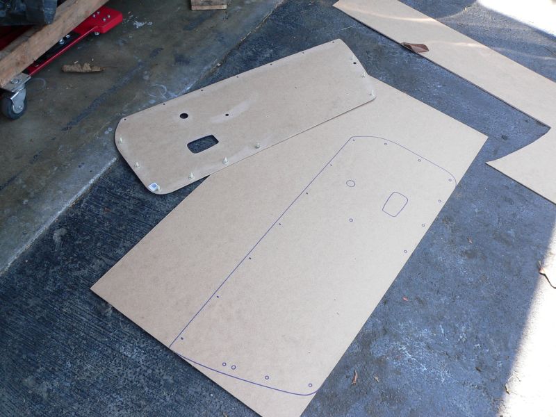
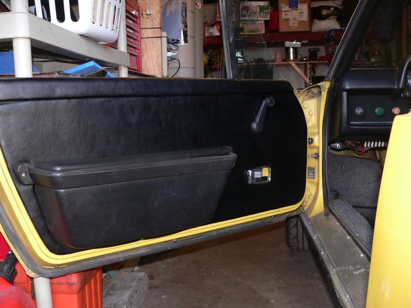
Posted by: TonyAKAVW Jul 18 2006, 01:30 AM
New tachometer sitting in place. not yet hokoed up. I guess now I need to get spunone's guage bezels for the remaining stock gauges.
Also got the radiator fans in place. Need to order some weatherpack connectors from Jeg's to wire them up, and put relays in the relay/fuse box.
It looks like I could have fit two 12 inch fans on but I didn't think it would work when I was ordering them. If I have heat problems that will be the first upgrade. I could then use this 10 inch fan on a motorcycle radiator or use it on the engine grill, etc.
-Tony
Attached image(s)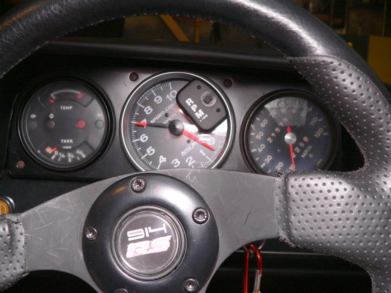
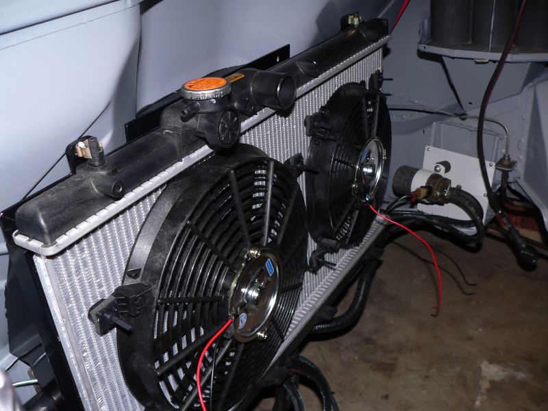
Posted by: TonyAKAVW Jul 18 2006, 01:31 AM
Last one for tonight...
Attached image(s)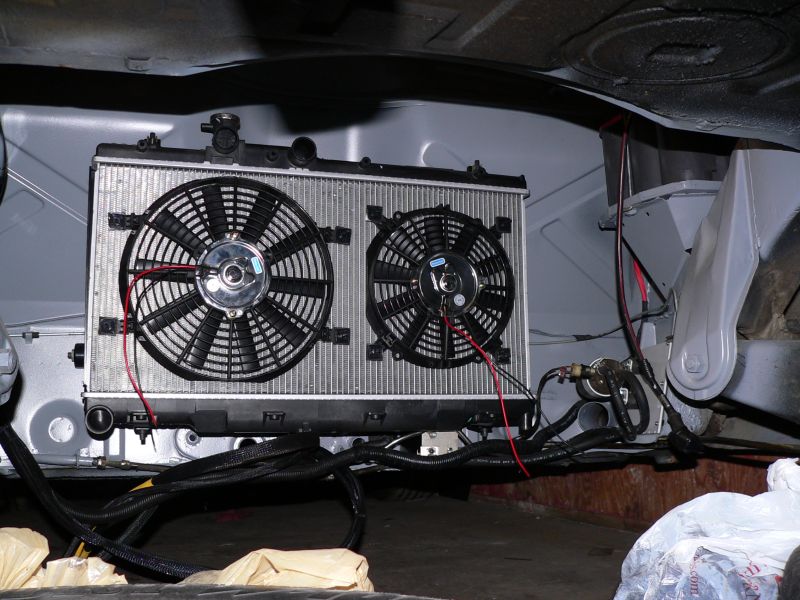
Posted by: TonyAKAVW Jul 18 2006, 01:36 AM
Neo9146: Nope, havent fired up the engine yet. I don't have a flywheel attached to it and pull starting it via the AC pulley might be kinda hard
Once I get the flywheel bolted on, clutch installed, and bolt the transmission together I could fire it up (without exhaust, which I'm sure my neighbors would LOVE). But I will probably wait until its installed in the car. That way I'm assured something will be wrong requiring me to pull the engine. Luckily I'll have no shift linkage to deal with and my trusty custom drivetrain dolley (which acts as a docking port for the transmission jack) will come in handy for those many one man engine drops.
Brad: good to hear about the KEP excessive lead time. Perhaps this thing will make it to the German Autofest after all.
-Tony
Posted by: Crazyhippy Jul 18 2006, 01:33 PM
I want to see it @ GAF... Get on it dammit
BJH
Posted by: fat73 Jul 18 2006, 02:38 PM
Last one for tonight...
Awesome work Tony...Hope that sucker cools.
Ed
Posted by: JPB Jul 18 2006, 03:39 PM
Nice work and you are inspiring us all!
Posted by: TonyAKAVW Jul 26 2006, 03:06 PM
Today I picked up a coolant expansion tank and cap from Importedcarparts.com (who happens to be down the street from me). This tank and cap are standard equipment on most Audis and VW made in the last few years. Its a really well made tank, far nicer than the ones you can get at FLAPS. Mounting may be trickier, but I'm sure I'll figure out something. The best part about it is that its high quality and cheap! $16 for the tank and $5 for the cap.
-Tony
Attached image(s)
Posted by: Aaron Cox Jul 26 2006, 03:10 PM
my passat had that tank...
albeit with a crack LOL
Posted by: JPB Jul 26 2006, 04:28 PM
Dangit bro, make it go so we can see how cool she will run!
 Go go gadget swullem member!!!
Posted by: eric914 Jul 28 2006, 07:08 AM
When wiring my EJ20 motor I found the following source for WeatherPac connectors. Good price and fast shipping.
http://koskowskimotorsports.com/kms/index.php?cPath=21_43
Posted by: TonyAKAVW Jul 28 2006, 11:09 AM
For connectors I ended up going with something other than Weatherpack connectors. I used something fairly similar made by Molex called a mate-n-lok conenctor. They are really cheap, water proof and well made.
I ordered them through Digikey, got a few spares for stuff I still need to do like the O2 sensor and VSS. Speaking of VSS, I also ordered a few Hall effect sensors from Digikey. These are made by Melexis semiconductor and are self-contained 3-pin Hall sensors, made for the automotive environment. At $1.87 each they are a bargain compared to an OEM sensor at as much as $80-$90. Even packaged hall sensors tend to be in the $30-$40 range. I'm packaging these in small glass vials potted with epoxy. Hopefully this weekend I'll finish them up and post pictures.
-Tony
Posted by: phantom914 Jul 28 2006, 11:25 AM
For connectors I ended up going with something other than Weatherpack connectors. I used something fairly similar made by Molex called a mate-n-lok conenctor. They are really cheap, water proof and well made.
I ordered them through Digikey, got a few spares for stuff I still need to do like the O2 sensor and VSS. Speaking of VSS, I also ordered a few Hall effect sensors from Digikey. These are made by Melexis semiconductor and are self-contained 3-pin Hall sensors, made for the automotive environment. At $1.87 each they are a bargain compared to an OEM sensor at as much as $80-$90. Even packaged hall sensors tend to be in the $30-$40 range. I'm packaging these in small glass vials potted with epoxy. Hopefully this weekend I'll finish them up and post pictures.
-Tony
Digikey rocks!
 Which connectors? The mate-n-locks I saw were not sealed, although they were made by AMP I believe. Did you consider the "waterproof automotive type connectors" on pg 263? Did you notice the "ASSMANN" computer cables (pg 44)
  I heard the LEGGMANN stuff is better.
Andrew
Posted by: TonyAKAVW Jul 30 2006, 11:21 PM
Weekend update:
I built a Vehicle Speed Sensor (VSS) this weekend. It uses a Hall effect sensor from Melexis Semiconductor (its a German made part!) and cost me a whole $5 to build. This compares to $80-$100 for the stock Subaru VSS. I still have to figure out where to mount magnets (requires one of polarity, the sensor is a 'latch.')
Today I decided to put the engine and transmission into the car to check for clearances and see that things fit. Well, things don't fit 
Here's a list of issues I need to take care of:
1. Alternator runs into part of the radiator. Need to lower the alternator and get a shorter belt. Easy fix.
2. Radiator fans are too close to the crank pulley and alternator. Need to put fans on the other side of the radiator. Another easy fix.
3. Intake simply doesn't fit. Need to cut some of the tubing to bring it in closer, probably need to redo the bracket I made. Not so easy fix, but not a show stopper.
So thats pretty much it for fitment issutes. I still need to find a good location for my coolant reservoir. Once I have the engine in and mounted up I'll work on making up a bracket for it.
Other things I noticed while the engine was in the bay...
The engine cover shroud will really have to cover the whole engine. I'm thinking a large sheet of thin aluminum will do the trick. This will keep rain off the engine.
Lastly, I picked up a couple more 12 inch radiator fans at an electronics swap meet yesterday for $5 a piece. These are going to go on the engine bay lid to help with cooling. Its going to be cramped, so I might only get one in.
Hopefully the new flywheel and pressure plate, clutch etc. comes in early this week. Once I get those installed, the engine/trans will go together for good (until I realize I need to adjust it). Assuming all that happens and I fix these fitment issues this week I may be ready for a fire-up next weekend. Chances are though it will be two weeks. These issues will all take some time to figure out, and I've never installed a clutch before.
-Tony
Posted by: Dr. Roger Jul 31 2006, 01:48 AM
patience of a saint.
methodical like a mo fo. LOL
great work.... again. =-)
Posted by: TonyAKAVW Aug 6 2006, 09:38 PM
Update for this weekend...
Getting closer! Yesterday I installed the new KEP flywheel, Sachs clutch disc and pressure plate. I was about to install the throwout bearing when I discovered the ball cup bushing is totally wasted (someone should make a bronze replacement) and the piece that holds the clutch arm to the ball was wasted. Additionally I found that two of the bolts I was using to hold the adapter plate on were too short, so I've got to get a couple more of those before putting this thing into the car.
The radiator fans are fixed (re-arranged them) and the alternator bracket is fixed (need new belt still). Intake and coolant tank bracket fabrication began as well.
First picture is my Vehicle Speed Sensor (VSS) that I made. As a troubleshooting aid, I have a green LED inside this thing. This way I can look to see if the sensor is working rather than trying to measure a signal. Still need to seal the thing with silicone. Also need to make a bracket to hold it onto the transmission. If I someday go with an electronic speedometer I wil get rid of the stock speedo drive cable and modify the right angle drive to work with this sensor, or maybe even fabricate a new sensor. I'm all for getting rid of mechanical cables.
-Tony
Attached image(s)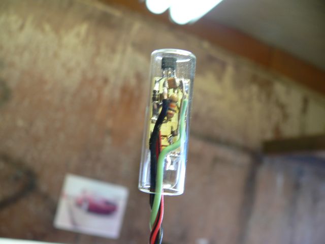
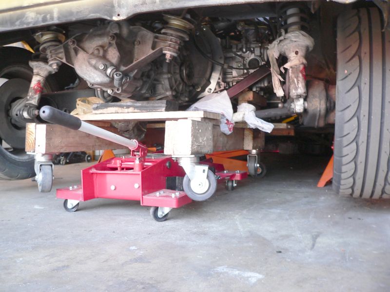
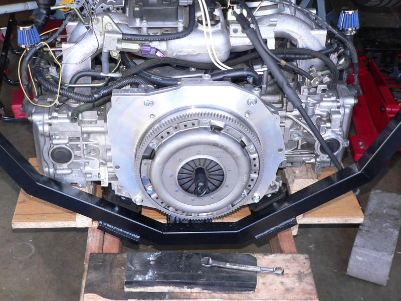
Posted by: TonyAKAVW Aug 14 2006, 01:00 AM
Got a LOT done this weekend.
Installed engine and transmission - fixed the mounting plates and installed the aluminum shim.
Installed the starter
Bolted up the CV joints to transmission - new bolts, correct lock washers, gaskets
Installed all coolant hoses except from the reservoir to the radiator.
Installed speedometer drive cable
Installed accelerator cable
Installed coolant reservoir
Connected fuel lines using high pressure fuel hose.
-------
Major things left to do:
Exhaust system - mandrel bends are on there way from Summit, need to order mufflers and O2 sensor still
Cable shifter setup - need to order cables and machine the transmission end parts.
Other than that I have a few minor things like wiring up the starter and alternator.
Question....
The Subaru engine has a fuel pressure regulator with a return to the fuel tank. The fuel pump I'm using also has a return. Should I use a TEE so that both returns can go to the tank or should I just cap off the fuel pump and use the Subaru pressure regulator?
-Tony
Attached image(s)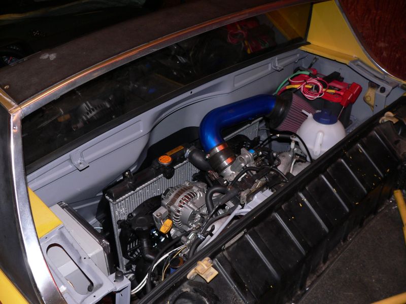
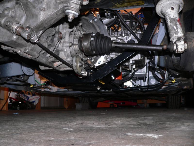
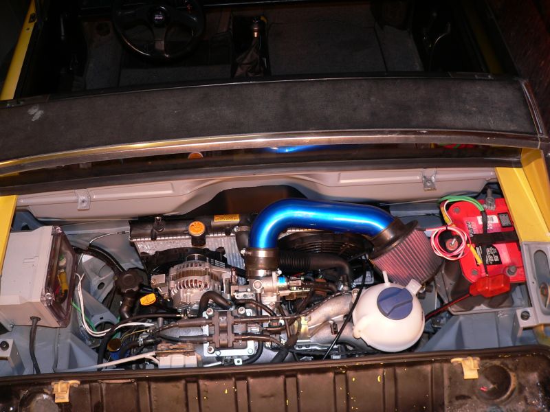
Posted by: bondo Aug 14 2006, 01:06 AM
That's looking pretty sweet!
Posted by: fat73 Aug 14 2006, 06:44 AM
Got a LOT done this weekend.
Installed engine and transmission - fixed the mounting plates and installed the aluminum shim.
Installed the starter
Bolted up the CV joints to transmission - new bolts, correct lock washers, gaskets
Installed all coolant hoses except from the reservoir to the radiator.
Installed speedometer drive cable
Installed accelerator cable
Installed coolant reservoir
Connected fuel lines using high pressure fuel hose.
-------
Major things left to do:
Exhaust system - mandrel bends are on there way from Summit, need to order mufflers and O2 sensor still
Cable shifter setup - need to order cables and machine the transmission end parts.
Other than that I have a few minor things like wiring up the starter and alternator.
Question....
The Subaru engine has a fuel pressure regulator with a return to the fuel tank. The fuel pump I'm using also has a return. Should I use a TEE so that both returns can go to the tank or should I just cap off the fuel pump and use the Subaru pressure regulator?
-Tony
Tony...I haven't hooked up my fuel pump yet (928 pump) but it doesn't have a builtin return, so I'd say use what came with the engine. You might want to ask the guys on the yahoo subaru vanagon forum. btw- some new pics on http://community.webshots.com/user/fat73
Ed
Posted by: fat73 Aug 14 2006, 07:31 AM
Got a LOT done this weekend.
Installed engine and transmission - fixed the mounting plates and installed the aluminum shim.
Installed the starter
Bolted up the CV joints to transmission - new bolts, correct lock washers, gaskets
Installed all coolant hoses except from the reservoir to the radiator.
Installed speedometer drive cable
Installed accelerator cable
Installed coolant reservoir
Connected fuel lines using high pressure fuel hose.
-------
Major things left to do:
Exhaust system - mandrel bends are on there way from Summit, need to order mufflers and O2 sensor still
Cable shifter setup - need to order cables and machine the transmission end parts.
Other than that I have a few minor things like wiring up the starter and alternator.
Question....
The Subaru engine has a fuel pressure regulator with a return to the fuel tank. The fuel pump I'm using also has a return. Should I use a TEE so that both returns can go to the tank or should I just cap off the fuel pump and use the Subaru pressure regulator?
-Tony
Tony...
Where do you get the project box mounted in your engine bay you used for your electronics?
Ed
Posted by: fiid Aug 14 2006, 09:53 AM
I don't think you can use a stock pump - because it's designed to fit IN the fuel tank. I've never seen one, so I don't know if it can be adapted or not.
As for the current situation - I think I'd try T-ing the two lines together to return to the tank... perhaps run the pump and measure your fuel pressure (I have a spare Oil Pressure guage I use for this - which you can get from FLAPS for not much $$$).
I upgraded my pump to a Walbro 255 l/hr pump. They have a universal model which mounts in a neoprene sleeve. Mine sits just below the battery (an optima). It's much quieter than the stock pump. I also changed to a subaru spec filter which is a little different from the 914 filter - I think mainly in terms of higher flow rate and longer lasting (bigger). The walbro pump just has input and output, so the return line is a direct hookup to the fuel pressure regulator.
QUESTION:
Have any of you subaru peops had problems with air getting trapped in the heater loop of the cooling circuit?
Posted by: TonyAKAVW Aug 14 2006, 11:13 AM
I bought it at a local suprlus electronics place maybe a year ago. It was the only one of the size they had. Not sure where you'd find something like that for a reasonable price. I payed maybe $10 for it (brand new).
I think a T-junction will be the way to go with the fuel pump. I bought a brass T-junction at my FLAPS yesterday, so I'll hook it up and I suppose that will work.
-Tony
Posted by: Aaron Cox Aug 14 2006, 11:19 AM
sick....
Posted by: GS Guy Aug 15 2006, 06:21 AM
Ed,
Looks like one of these:
http://www.integraenclosures.com/Cat3/PremiumHT.asp
I think McMaster Carr also sells some limited sizes of these boxes.
Jeff
Tony...
Where do you get the project box mounted in your engine bay you used for your electronics?
Ed
Posted by: fat73 Aug 15 2006, 09:31 PM
Ed,
Looks like one of these:
http://www.integraenclosures.com/Cat3/PremiumHT.asp
I think McMaster Carr also sells some limited sizes of these boxes.
Jeff
Tony...
Where do you get the project box mounted in your engine bay you used for your electronics?
Ed
thx
Posted by: Crazyhippy Aug 16 2006, 01:21 PM
Radio shack carries a few sizes of project boxes, but you need to find a electronics store to find LOTS of sizes. Went into one the other day and they had 15 different sizes at least.
They also had the 14 pin IDP connector i needed (.75 cent project stopper....)
BJH
Posted by: TonyAKAVW Aug 16 2006, 02:49 PM
There are a few cool features of the box I bought that you won't find in Radio Shack boxes. First, they tend to be fairly small. Second, this one is very heavy duty. The plastic is around 0.2 inches thick, and the front cover is a clear plastic hinged type. The screws that hold the lid shut use metal threaded inserts so the plastic of the box won't strip out from repeated opening and closing. There's also molded-in standoffs at the bottom of the box for mounting either a printed circuit board or other objects. This way you don't have to drill holes in the bottom for screws and standoffs.
I've built many many electronics projects and finding good cabinets/housings is always one of the hardest parts. I got lucky with this one.
In other news...
Went to a muffler/exhaust shop down the street from me at lunch today. Took a look at some mufflers etc. Tonight I'm going to mock them up in cardboard, place them where I want them and start figuring out how to route tubing. I received several mandrel bent tubing pieces from Summit on Monday, which I'm going to cut up to fit.
-Tony
Posted by: fat73 Aug 16 2006, 03:34 PM
There are a few cool features of the box I bought that you won't find in Radio Shack boxes. First, they tend to be fairly small. Second, this one is very heavy duty. The plastic is around 0.2 inches thick, and the front cover is a clear plastic hinged type. The screws that hold the lid shut use metal threaded inserts so the plastic of the box won't strip out from repeated opening and closing. There's also molded-in standoffs at the bottom of the box for mounting either a printed circuit board or other objects. This way you don't have to drill holes in the bottom for screws and standoffs.
I've built many many electronics projects and finding good cabinets/housings is always one of the hardest parts. I got lucky with this one.
In other news...
Went to a muffler/exhaust shop down the street from me at lunch today. Took a look at some mufflers etc. Tonight I'm going to mock them up in cardboard, place them where I want them and start figuring out how to route tubing. I received several mandrel bent tubing pieces from Summit on Monday, which I'm going to cut up to fit.
-Tony
Tony...
I haven't figured out what I'm going to do for exhausts yet either, but I only have one to deal with coming out of the turbo. However, I want to run Duals out the back, or possibly modify the back bumper to let the pipes come out F40 or GT40 style. One thing I found out you can do to mock up the exhaust was use those foam noodles kids use in the swimming pool. You can take those and put some of the thin strip aluminum through them or heavy wire and bend them around whichever way you want to figure it out and go from there.
Ed
1973 Porsche W9R1
Posted by: TonyAKAVW Aug 20 2006, 10:30 PM
At long last, the moment we (or at least I ) have been waiting for....
IT LIVES!!!! 
Its noisy but it runs great.
Only had a few wiring issues to take care of. There was a +12v line that was connected to ground, and blew a couple fuses. Found that pretty quickly and then discovered I had another short inside my sensor simulator box. Melted teflon smells funny. So I disconnected that wire, grounded the neutral position sensor, and fired it up.
Here's a video.
http://www.youtube.com/watch?v=PXv8mmqCL78
The sound isn't great, but you get an idea.
-Tony
Posted by: fat73 Aug 20 2006, 11:24 PM
At long last, the moment we (or at least I ) have been waiting for....
IT LIVES!!!!
Its noisy but it runs great.
Only had a few wiring issues to take care of. There was a +12v line that was connected to ground, and blew a couple fuses. Found that pretty quickly and then discovered I had another short inside my sensor simulator box. Melted teflon smells funny. So I disconnected that wire, grounded the neutral position sensor, and fired it up.
Here's a video.
http://www.youtube.com/watch?v=PXv8mmqCL78
The sound isn't great, but you get an idea.
-Tony
That is awesome, congratulations!
Does it have any exhausts at all yet? We spent all weekend working on getting the engine clean. I'm taking a bunch of stuff to get hi-temp coated tomorrow, and going to order a bunch of new nuts/bolts to replace the rusty stuff (Michigan engine). Hope to have the engine back together by the end of the week so we can start putting it in. When's the first test drive?
Ed
Posted by: banksyinoz Aug 21 2006, 12:47 AM


great work tony
thanks for the video im sure it will inspire many of us to remove our jackstands much sooner
Posted by: elwood-914 Aug 21 2006, 04:07 AM
Way to go Tony!! Thanks for sharing this thread though out the process. It was a big boost for the Suby conversions.
Posted by: mrdezyne Aug 21 2006, 08:17 AM
Ahhh, just hearing it run gives me new inspiration! Hopefully late this fall I can return the favor with a clip of my own.... Thanks Tony!
Posted by: Root_Werks Aug 21 2006, 09:07 AM
Posted by: fiid Aug 21 2006, 09:14 AM
Dude! Awesome! Nice work!!!
Is it running with no exhaust - or some other setup....?
This reminds me: I need to post a video of my car......
Posted by: WRX914 Aug 21 2006, 09:44 AM
Right on Tony!!!!
Sounds awesome. I am glad to see and hear that you are almost out of the woods. Can't wait to meet you and go for a hybrid drive!!!
Posted by: Rotary'14 Aug 21 2006, 10:02 AM
Woo Hoo!! Right on Tony!! 
Sounds cool. thanks for the video.
-Rob
Posted by: Aaron Cox Aug 21 2006, 10:22 AM
was way cool hearing it live. thanks for the call tony!
Posted by: TonyAKAVW Aug 21 2006, 10:51 AM
Thanks! I was pretty ecstatic yesterday. I terrorized the neighborhood by calling my friends and saying "You want to hear something cool? " and then firing up the engine.
Currently it has no mufflers or exhaust other than the Outback Motors primary collectors. It also has no O2 sensor, so its running rich. When I blip the throttle it makes funny noises on decel. Once I get everything installed I'm sure it will kick ass. It idles super smooth as it should.
I can't wait to get it on the road!
I still have a couple more weeks of work on it (finish cable shifter, install exhaust and mufflers, etc.)
-Tony
Posted by: cbenitah Aug 21 2006, 10:57 AM
Awesome job Tony!!
Posted by: Aaron Cox Aug 21 2006, 11:10 AM
get'r done by GAF
Posted by: WRX914 Aug 21 2006, 11:55 AM
Tony,
Look up crawford performance - www.crawfordperformance.com
They are located in Oceanside. I brought my teener to them on Saturday morning they can put a STI engine in our teeners no problems. They are currently getting up to 700hp with a 2.5 liter STI engine. My car is there getting dyno tuned, they should be able to increase my HP by approx 40%. If you call, ask for Quirt Crawford. He is simply awsome...
Keith
Posted by: TonyAKAVW Aug 21 2006, 11:59 AM
Cool! I'm running the stock ECU so I don't know how much tuning range there is in that. I've been told that Outback Motors can get 190 HP out of a stock EJ25 by using their maps on a Link system. I'm not really ready yet to mess with tuning the engine, but I'm sure that will come sooner than I imagine.
-Tony
Posted by: phantom914 Aug 21 2006, 12:05 PM
Allright Tony!
So you called your friends huh? I guess that's why I didn't find out about this until I read it here. 


Andrew
Posted by: WRX914 Aug 21 2006, 12:08 PM
Cool! I'm running the stock ECU so I don't know how much tuning range there is in that. I've been told that Outback Motors can get 190 HP out of a stock EJ25 by using their maps on a Link system. I'm not really ready yet to mess with tuning the engine, but I'm sure that will come sooner than I imagine.
-Tony
I am running the WRX stock ecu and they can get ALOT out of these ECU's I mean ALOT!!! If I were you, I would call them...
My ECU is getting a licensed reflash, if I ever have a problem, I call them give them the ODBII code and they email me the file to correct the problem. Also if there are any improvements to the system, they provide the updates free of charge. The ECU dyno tune starts at $1,000.00 but in my opinion, worth every penny. Within two minutes of bringing my car to them, they had it running 100% better. I simply can not wait to get it back.
Keith
Posted by: WRX914 Aug 21 2006, 12:20 PM
can you help me post a video?
tx
Ketih
Posted by: jsteele22 Aug 22 2006, 03:23 PM
Awesome video, Tony. A couple of observations :
1) Glad the thing was in neutral when you fired it up !!!
2) The video was so short ! I coulda watched/listened for a long time.
3) You don't look as much like Napoleon D. as I thought you would....
4) Sounds like you're all ready to drive to RRC; registration deadline is Friday...
Congrats on all the hard work - now, officially, you are the man.
I kinda wasted my summer not getting much done on my car; I'll prolly have a ton of questions for you next summer...
Cheers,
Jeff
Posted by: TonyAKAVW Aug 22 2006, 03:51 PM
Yes, I made sure it was in neutral! And I had the parking brakes on as well as a brick behind one of the rear wheels.
I still can't drive the car as it has no exhaust system and no gear shifter. Both of those things should see significant progress over the next couple weeks.
I'd love to do the RRC, but we'll be in Italy or Switzerland at the time.
I'll take a longer video once I get the gear shifter installed. Right now the transmission is dry and I don't want to leave it rotating for very long.
One thing I want to do though is take some really good recordings of the sound.
-Tony
Posted by: JPB Aug 22 2006, 03:57 PM
I'm curious to see how cool she runs Tony. I wonder how it will work at high speeds over a few miles. Many love the rad thing and are anxious to see it do it's thing!
Posted by: TonyAKAVW Aug 22 2006, 04:28 PM
I'm also anxious to see how it does with heat. I have several ideas in mind because I know that with just two fans, I won't have enough cooling capability. So here's my plan so far..
1. Drive the car until it gets hot. Watch the temperature and monitor it. (with engine bay lid)
2. Do the same but without engine bay lid
3. Modify engine bay lid to GT-style and add two more fans to push air into the engine bay.
4. Add a flap in front of the hot air exit under the car (like the 914 rubber flaps)
5. Build the diffuser setup as previously discussed in this thread
6. Build a retractable lip that sits behind the trailing edge of the roof to divert air into the engine bay
7. If all those things fail, reverse the flow of the fans to pull air from below and out the engine bay lid.
8. If all that STILL fails, buy a Renegade kit and sell out.
-Tony
Posted by: cbenitah Aug 22 2006, 04:43 PM
I like #8
But I know you will figure it out! If you have come this far what would stop you from not making it happen!
Believe in yourself and it will come.... (haha, I think I heard that some where)
Posted by: Dr. Roger Aug 22 2006, 06:16 PM
that's just plain HOT!
Posted by: JPB Aug 22 2006, 06:25 PM
I believe it will work but it will probably work best under way if you had some forced air ducting piped into it also.
You can do it!!!!
Posted by: Bill D Aug 22 2006, 07:54 PM
If all else fails before selling out how about moving the radiator where the stock muffler was? There is a jeep radiator 11" tall by 31" wide. I would think there would be other short radiators. Could that work?
Posted by: TonyAKAVW Aug 22 2006, 09:42 PM
If all else fails before selling out how about moving the radiator where the stock muffler was? There is a jeep radiator 11" tall by 31" wide. I would think there would be other short radiators. Could that work?
Not a bad idea. Though if I had to put the radiator on one end of the car or the other, I 'd rather have it up front to help even out the balance of mass.
There are a few other ideas I have like augmenting the single radiator with one or two motorcycle radiators, etc. I'm sure I'll figure out a good cooling setup. If I can't them I will have to turn in my License to Engineer.
-Tony
Posted by: mrdezyne Aug 23 2006, 08:36 AM
Just sharing my favorite quote, it helps me along when some "doubting Thomas" says there is no way my ideas will work...
"Creative ideas reside in people's minds but are trapped by fear of rejection.
Create a judgement-free environment and you will unleash a torrent of creativity"
Alex Osborn
NO SELLING OUT! We have followed you this far, now make it work dammit!
Posted by: Crazyhippy Aug 23 2006, 03:44 PM
Motorcycle radiators like Brant's racecar... ohhh yeah...
Would be a bit harder w/ headlights though.
Just keep the fingers crossed that it works the 1st time, and you wont have to do all the rest of that work.
BJH
Posted by: JPB Aug 23 2006, 03:56 PM
Sorry for asking the BIG QUESTION, didn't expect that many peeps to be questioning your AWSOME SETUP! There are a huge number of high power fans that will suck the hernia out of your rad bro!!! You have the dream setup we all needed to see and mimic!
The greatest form of flatery is immitation and we are all looking ta do the same thing. RUN THAT BEAST!!
Posted by: TonyAKAVW Aug 24 2006, 11:15 AM
Last night I figured out the problem with the accelerator cable. Turns out that there were two things wrong. First, the throttle cable was wrapped around the clutch cable. As Napoleon Dynamite would say 'FRICK'N IDIOT. GOSH!'
Secondly, the carpet seems to have been causing problems. So I'm going to cut out a couple small areas where it seemed to be binding up. I also lubricated the three ball/cup bushings. With those three things done the throttle works great now.
I also built a bracket for and installed the coolant temperature guage.
Today I'm picking up a part that Phantom914 machined for me (THANKS ANDREW!!!) for the cable shifter. The cables are set to arrive from McMasterCarr today as well. If all goes well I could have the cable shifter installed (meaning the car would be driveable) by Friday or Saturday.
I'll upload photos of the cable shifter as I get it built and installed. Hopefully it works well!
-Tony
Posted by: Headrage Aug 24 2006, 11:28 AM
WAY TO GO TONY!!!!!!!!!!!!!!!!!!!!!!
Get er done and drive it to the German Auto Fest next month.
BTW, you got a REEEEALY steep driveway.
Posted by: TonyAKAVW Aug 25 2006, 02:24 AM
As expected the cable shifter cables arrived today, as well as the last part I needed machined (THANKS PHANTOM914). So right after I got home from work I started getting the parts put together and the cables installed. Didn't quite finish but I got half the gear selection working. I figure another 4 hours and this thing will be fully functional.
Attached image(s)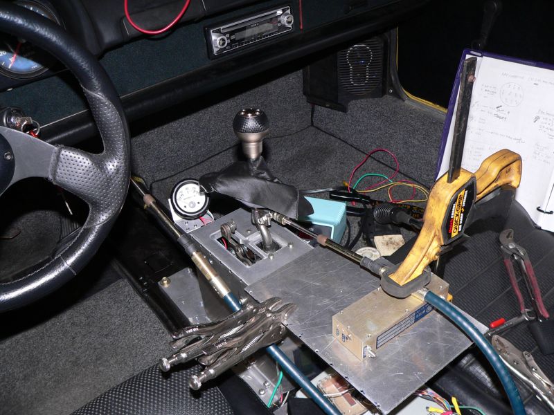
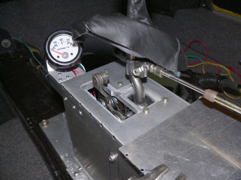
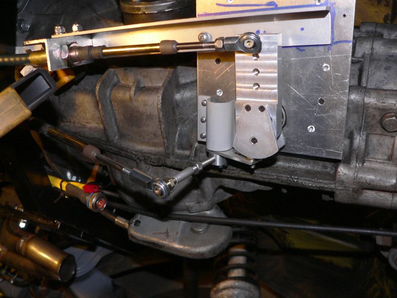
Posted by: TonyAKAVW Aug 25 2006, 02:26 AM
Couple more pictures. Also the linkage between the Subaru and 914 throttle cables.
Attached image(s)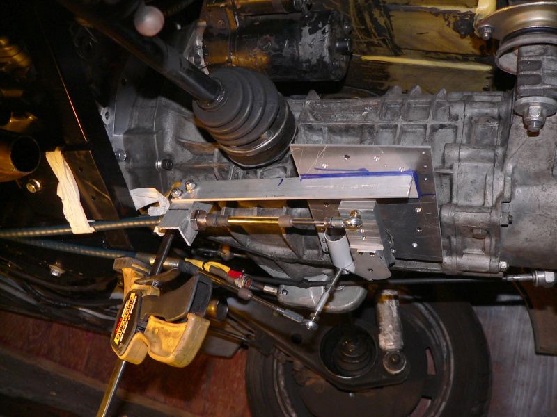
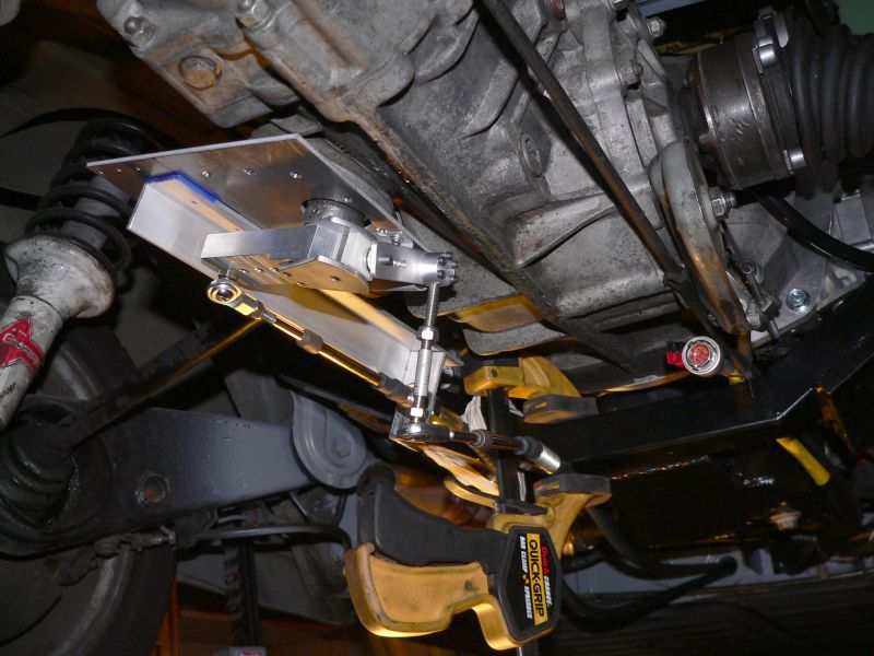
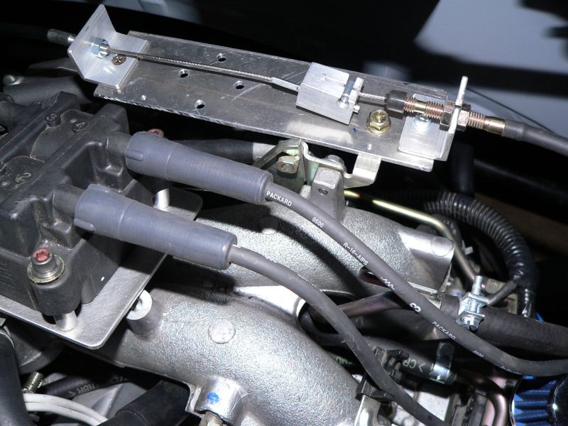
Posted by: TonyAKAVW Aug 25 2006, 02:30 AM
So far the forward-backward action on the shifter is great. The only slop is from the transmission itself. These cables are humongous. I definitely didn't expect them to be as big as they are. However they both fit through the original shift rod hole with no problem. I've still got a couple brackets to make and need to take care of the in/out movement (in the pictures its hooked up but rather poorly). So Saturday I'm expecting to try this thing out on the road. It won't have an exhaust and undoubtedly the ECU will put the engine in 'limp home' mode, but I should be able to get an idea of how the shifter works.
-Tony
Posted by: phantom914 Aug 25 2006, 08:44 AM
I would suggest smaller quick-grips on the transmission end, otherwise ground clearance may be a problem.
Also, looking at the first picture, I think the RF amp gain may be a little low for this application. Maybe you can find out which amp is included in the Renegade kit and use that one. No sense reinventing the wheel.
Otherwise, good job!
Andrew
Posted by: fat73 Aug 25 2006, 12:12 PM
I would suggest smaller quick-grips on the transmission end, otherwise ground clearance may be a problem.
Also, looking at the first picture, I think the RF amp gain may be a little low for this application. Maybe you can find out which amp is included in the Renegade kit and use that one. No sense reinventing the wheel.
Otherwise, good job!
Andrew
RF Amp gain? I have the complete Renegade kit and can't say I recognize that one..
Ed
Posted by: WRX914 Aug 25 2006, 12:16 PM
I would suggest smaller quick-grips on the transmission end, otherwise ground clearance may be a problem.
Also, looking at the first picture, I think the RF amp gain may be a little low for this application. Maybe you can find out which amp is included in the Renegade kit and use that one. No sense reinventing the wheel.
Otherwise, good job!
Andrew
RF Amp gain? I have the complete Renegade kit and can't say I recognize that one..
Ed
Agreed, there is no Amp gain with the Renegade kit...

Posted by: bondo Aug 25 2006, 12:30 PM
I would suggest smaller quick-grips on the transmission end, otherwise ground clearance may be a problem.
Also, looking at the first picture, I think the RF amp gain may be a little low for this application. Maybe you can find out which amp is included in the Renegade kit and use that one. No sense reinventing the wheel.
Otherwise, good job!
Andrew
RF Amp gain? I have the complete Renegade kit and can't say I recognize that one..
Ed
Agreed, there is no Amp gain with the Renegade kit...
In the first pic, he's using an RF amplifier under the quick clamp, as a spacer. It was a nerd joke.
Posted by: TonyAKAVW Aug 25 2006, 12:40 PM
Gosh, doesn't everyone have junk bins full of surplus electronics?
Well, its not just a function of gain Andrew. This amplifier has a particularly high IP3 and low noise figure. For my shifter I want to make sure my adjacent channel interference doesn't saturate the front end.
-Tony
Posted by: phantom914 Aug 25 2006, 01:04 PM
Gosh, doesn't everyone have junk bins full of surplus electronics?
Well, its not just a function of gain Andrew. This amplifier has a particularly high IP3 and low noise figure. For my shifter I want to make sure my adjacent channel interference doesn't saturate the front end.
-Tony
OK. I was just trying to save you some trouble, but it looks like you thought this out well enough.
Andrew
Posted by: jsteele22 Aug 25 2006, 08:01 PM
Well, its not just a function of gain Andrew. This amplifier has a particularly high IP3 and low noise figure. For my shifter I want to make sure my adjacent channel interference doesn't saturate the front end.
-Tony
Let me know how this works out for you. I've had a few saturation problems in my front end. Had been thinking of low-tech solutions, like replacing weather stripping, but I think a modular RF amp would be cheaper
Also, I disagree about the Quick Grips. I think the black handles are a nice match with the steering wheel, shift knob, and soldering iron.
It's looking awful clean, Tony. If this were the 80's, Id say it looks righteous.
Posted by: Aaron Cox Aug 25 2006, 08:30 PM
quite the tower for the shifter!
now i know why my fuch hasnt been cut into a clock yet  LOL
LOL
Posted by: Dr. Roger Aug 26 2006, 12:38 PM
it's one thing if a V8 car drags a rubber cooling hose on a speed bump but quite another thing if that rear trans linkage shoves the in/out shaft into the tranny. IMHO. =-)
i just dont want to see you on the side of the road someday with a jacked-up tranny.
i like that the shifter is high. coooool.
Posted by: JPB Aug 26 2006, 04:20 PM
Nice engineering Tony!!! I like to over engineer stuff and dosen't seem to heavy to me. Good job!
:beer1:You make me look lazy.
Posted by: TonyAKAVW Aug 26 2006, 11:03 PM
I redid the linkage setup for the side-side movement today and it looks much better, doesn't hang down as far. The other thing is that this shifter stuff sits roughly between the two wheels. Its highly unlikely that a speed bump would affect this stuff.
In other news I drove the car for the first time today!!!!! First drive was with no mufflers and was insanely loud. So I decided to clamp the mufflers on temporarily and that helped a lot. Still a lot of leaking exhaust, so its rather loud.
So initial impressions after driving.
1. LOUD - exhaust will fix this
2. Shifter is backwards! 1st is Rev. 2nd is 3rd, 4th is 5th. The pivot point for the side-side movement is on the wrong side. This is a simple fix, just relocate the bearing and flip over the linkage.
3. Side-side movement is touchy. The range of motion on the shifter is small. I think I need to lengthen or shorten a lever arm somewhere.
4. Getting into 1st is hard. I'm not sure if this is a function of the shifter mechanism or the transmission. At this point its hard to tell. The transmission has been sitting for some time and I don't know its condition other than what I was told (that it was in really good shape). There was no grinding from bad synchros etc., but this is definitely something to investigate.
5. The battery was dead. Also I'm not sure if the alternator is charging. The battery voltage doesn't go up to 13.8 when running, but that could be because the optima is sucking down amps, loading the alternator.
6. Even without an O2 sensor, and my sensor simulator box out of commision (meaning that the engine is in limp mode) the motor pulls hard. I never got to more than 1/3 or maybe 1/2 due to noise concerns. I'm excited to see how this thing will run with everything hooked up properly.
Tomorrow I'm going to try to get my muffler bracket made. First though I want to work on the shifter and see if I can get it shifting better. I don't want to hand over the car to the muffler shop without it shifting well. If all goes well I will take it in to the shop Monday or Tuesday.
-Tony
Posted by: phantom914 Aug 26 2006, 11:51 PM
Posted by: TonyAKAVW Aug 27 2006, 12:03 AM
It is cool! I hadn't thought about the shifter position in a long time ( I did intentionally put it high) and when I drove it today I realized that having the shifter up higher is really nice. For me at least its a much better position than the stock location. I'm not so sure I'm thrilled with the MR2 shifter mechanism, but it will do for now. The majority of the slop now seems to be inside the transmission.
-Tony
Posted by: fat73 Aug 27 2006, 09:54 AM
I would suggest smaller quick-grips on the transmission end, otherwise ground clearance may be a problem.
Also, looking at the first picture, I think the RF amp gain may be a little low for this application. Maybe you can find out which amp is included in the Renegade kit and use that one. No sense reinventing the wheel.
Otherwise, good job!
Andrew
RF Amp gain? I have the complete Renegade kit and can't say I recognize that one..
Ed
Agreed, there is no Amp gain with the Renegade kit...
In the first pic, he's using an RF amplifier under the quick clamp, as a spacer. It was a nerd joke.
No kiddin
 But if they had one I would have bought it by now.
Posted by: TonyAKAVW Sep 5 2006, 12:46 AM
Haven't updated this in a while and I've gotten a lot done.
In summary, I drove the car to work last week and it had several issues. The shifter fell apart, the engine overheated, and it went into limp-home mode. Also the tachometer was showing the wrong numbers, and the alternator wasn't charging.
The cooling problem was fixed by replacing my temp sensor splice with a piece of metal pipe instead of plastic that melted out of shape during the overheat event, as well as bleeding air out of the cooling circuit. I tested the cooling system and it cycles properly now.
I haven't had enough time behind the wheel to see how well it cools, but in anticipation of it not cooling enough I have begun modifying the engine bay lid for a pair of fans to bring in cool air from above.
I cut the two wires on the tachometer for the 4-cylinder engine operation, but it seems to be reading about twice as many RPMs as it should. I'm wondering if I should configure it for a 6 cyl engine. Probalby will check NASIOC or Autometer's web site for this.
The shifter has been fixed in two ways. First, the nylon plastic piece that raises or lowers the shifter bar into/out of the transmission has been lengthened to keep it from falling out. The bolts that hold the shifter arm to the shift rod came loose and I think I need to replace them with cap head scerws and loctite them in place.
The alternator is now charging properly. I ended up replacing the alternator, but when the new one didn't work, I knew I had wired up something wrong. The easy fix was to wire the remaining wire to the generator light on the combination meter.
The remaining biggest isue is the limp-home mode that its stuck in. It refuses to go above somewhere around 4000 rpms. After disconnecting the battery for a while it seems to reset the ECU and I can drive a short while until it comes back. Getting this stuff fixed is one of my priorities this week. Those last 2700 or so RPMs give a LOT of power.
I made a bunch of noise today by cutting holes in the rear bulkhead and the rear trunk for the exhaust S-bends. These S-bends will take exhaust from the mufflers to exhaust tips on either side of the bumper. After I get everything working I'll have to weld u the rear trunk to cover the exposed exhaust pipes.
Its looking like getting to the German Autofest with this car is goign to be a close call. I was hoping that this weekend I would fabricate the diffuser and really get the cooling system workign well enough for the toughest part of the trip, the ascent of the Sepulveda Pass, and back up on the back side.
And now, some pictures.
-Tony
Attached image(s)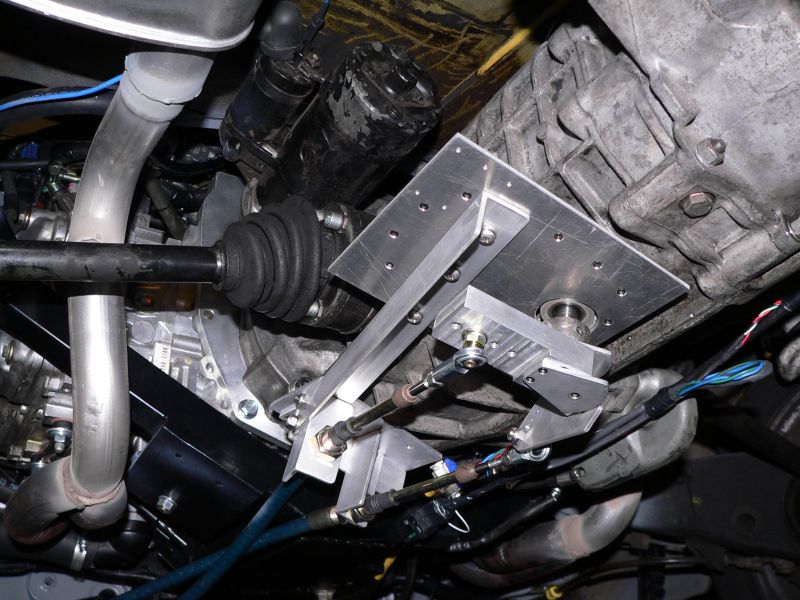
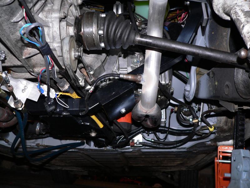
Posted by: TonyAKAVW Sep 5 2006, 12:48 AM
...
Attached thumbnail(s)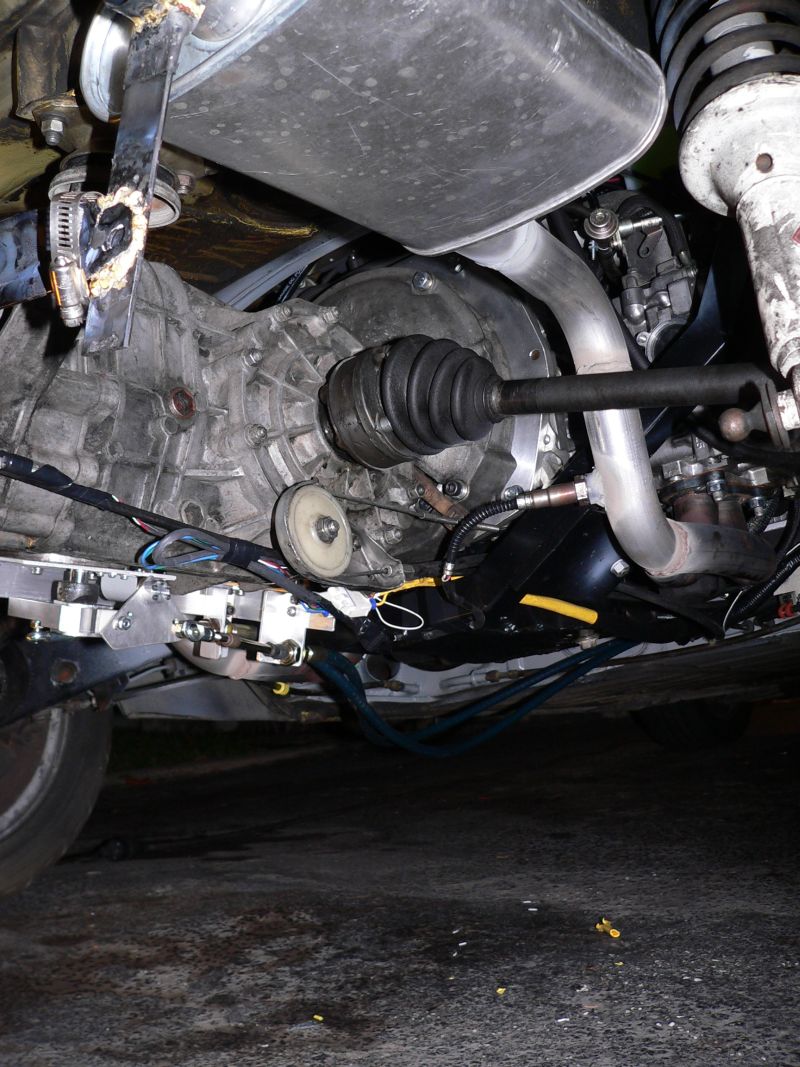
Attached image(s)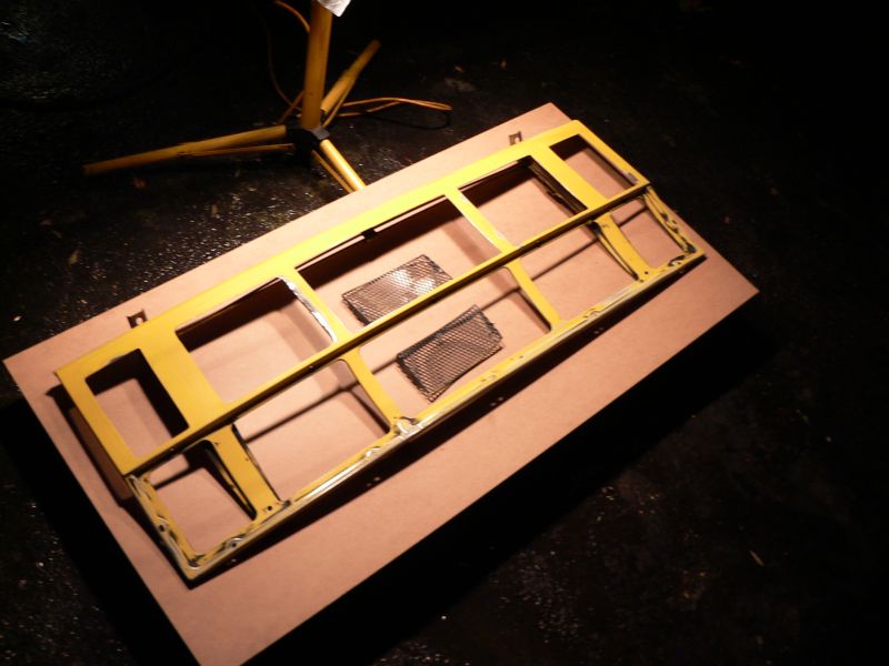
Posted by: WRX914 Sep 5 2006, 09:18 AM
Here is how I took care of my limp mode problem.
You need to take the car to someplace that can clear the RAM. If you have gone down to AutoZone and bought a ODBII scanner/reader you can only clear the cashe but not the RAM. You need to clear the "hard codes"...
I think you can also disconnect the ECU From the battery for a couple of hours as well...
Posted by: Dr Evil Sep 5 2006, 09:29 AM
I have heard that hard codes clear when you do what WRX said, AND short the power leads together to kill any internal power reservoir. This negates the hours of wait.
Posted by: jsteele22 Sep 5 2006, 10:49 AM
Hey Tony,
I'm curious about the exhaust. I know you're got the outback headers, and the pic shows the tube going over the axle (nice) and through a muffler. I was suprised that you needed to cut the trunk - was this so you could use stock bends ? I haven't poked my head "down there" for a while, but I thought that there would be room where the stock muffler is located to run to tailpipes w/ no cutting. When you get time to snap more pics, I'll be eager to see 'em.
p.s. Glad to hear that the cooling bugs are working themselves out.
Posted by: TonyAKAVW Sep 5 2006, 12:22 PM
I had to cut the trunk just at the very back because I am having the exhaust exit through the bumper, as in this modified picture...
I'm sure it will look better in real life..
-Tony
Attached image(s)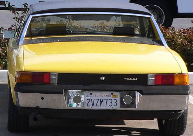
Posted by: Aaron Cox Sep 5 2006, 12:23 PM
nooooooooo not thru a chrome early bumper!!!
Posted by: TonyAKAVW Sep 5 2006, 12:40 PM
Nonono, the chrome early bumper is no longer in my posession. Thomas has it now. I'm going with fiberglass Getty bumpers. Gotta pick those up tomorrow or thursday.
-Tony
Posted by: Howard Sep 5 2006, 12:51 PM
Its looking like getting to the German Autofest with this car is goign to be a close call. I was hoping that this weekend I would fabricate the diffuser and really get the cooling system workign well enough for the toughest part of the trip, the ascent of the Sepulveda Pass, and back up on the back side.
-Tony
Looking good, Tony. Miss the Sepulveda pass (and steeper Camarillo grade) by just coming up PCH. Prettier ride, too.
Posted by: TonyAKAVW Sep 7 2006, 01:52 AM
Wednesday night, 3 more days until German Autofest. Hard to say if its going to be done in time.
I hooked up the two extra fans tonight and faked out almost all the rest of the sensors. I discovered that the vehicle speed sensor is supposed to send back a 0-5 volt signal, not 0-12. So I will probably just put a potentiometer across the input to the ECU and scale it down to 5 volts from 12. Also I need to figure out how to trick the heater sensor signal for the rear O2.
The results of tonight's test drive are that it still goes into limp home mode, and since I don't have my code scanner I can't yet tell why.
Another result is that with 4 fans going, the car vibrates a lot! Not sure that's going to be a long term solution, as its kind of annoying.
And the last result which I'm not thrilled about is that the cooling achieved by 4 fans (two on the radiator, two forcing cool air into the engine bay) doesn't seem sufficient. I drove around for probalby 15 minutes or so and got it up to temperature. It never went over 210, but being that it was 10:30 at night and probably 70 degrees out I would have hoped for better, considering that I was just going from stoplight to stoplight, and not really stomping on it that hard.
In these conditions it did reasonably well, but I highly suspect that its far from enough for any kind of spirite daytime driving. Unfortunately I won't get to really test it during the day until Saturday. Saturday I will need to come up with whatever aerodynamic aides I can. Fabricating an underbody diffusor even out of sheet aluminum on one day is going to be a huge challenge. The easier thing to try might be a small spoiler behind the targa bar's trailing edge, shooting air down into the engine bay.
This is a challenging and interesting part of this project really and unfortunately its probalby going to be too late for making it to the German Autofest. But there have been miracles in the past.
Tomorrow I get my OBDII reader back and should be able to see what is causing my troubles.
-Tony
Posted by: bondo Sep 7 2006, 12:22 PM
The technical name for the limp home mode is "Limp to GAF mode".
Posted by: Aaron Cox Sep 7 2006, 12:34 PM
Tony....
"THE EGGS ARE IN THE BASKET, AND ARE READY FOR DELIVERY"
Posted by: WRX914 Sep 7 2006, 01:43 PM
Alright, don't worry too much. Sounds like you are going through all the same crap as I did. You are at the end of the forrest, all you have to do is step out of it (so to speak). I know it is frustrating... but aside from your cooling issues, I think it is something small like a MAP or MAF sensor that is screwed up or something small like that. Your ECU will tell you all of your issues. If you simply can not get it figured out, do what I did and call Crawford and be driving it home in a week.
Bust ass on this Tony! Hopefully your cooling issues are all ironed out soon.
Keith
Posted by: andys Sep 7 2006, 01:56 PM
Tony,
Just a couple of thoughts with respect to your cooling issue. If indeed the radiator is not getting a sufficient flow of air through its' core, I would suggest you focus on the negative air pressure side of it. Generally, it is more effective to create a negative pressure side. Trying to force air through by means of an intake system is usually unsuccessful without adequate exit side negative pressure. I suspect that you'll need to do some experiments in your case.
Easiest way I found, was to get yourself some cardboard boxes, duct tape, a straight edge, and a razor knife. Start mocking up some spoilers/ducts (tape the h*ll out of it!), whatever it takes, and do a test. Tape it in place nice and solid employing gussetts, etc. It's easy with cardboard. It doesn't have to last long or be pretty. Once you establish what works, re-create it in a permanent fashion. I've used this method many times at the track for both cooling system ducting, as well as some aero dynamic device testing. It's quick and easy.
Good luck; I'd like to see your car at the GAF if possible. I'll likely be there on Sunday.
Andys
Posted by: TonyAKAVW Sep 7 2006, 02:49 PM
Aaron: THANKS!!!!!!!!!!!!!
Keith: I'm thinking that at least part of the problem is that I don't have my VSS hooked up yet. I'll do that tonight if I get a chance. Then I'll check codes.
Andys: I had been thinking about using cardboard, but thanks for reminding me about that. My focus so far with respect to cooling has been all about the negative pressure side. Having a diffusor or suction vent under the car was always in my plans. Thanks for the tips!
-Tony
Posted by: Dr. Roger Sep 7 2006, 02:58 PM
i know i'm talking about apples and oranges but this data may help....
i was having creeping temp issues and checked all the usual issues with V8 cooling systems. (no, i didn't use renegades radiator. yes, i'm a rebel)
after all my little mods to bring the temps down i tried simply removing the hood so there would be zero exhaust resistance.
the results were excellent. so i'm driving my bebe around without a hood till fall when she goes back into hibernation. when spring time comes she'll probably have some leading edged lip hood similar to our friend wbergtho with the LS6 powered white 914.
best of luck.
roger
Posted by: andys Sep 7 2006, 03:11 PM
i know i'm talking about apples and oranges but this data may help....
i was having creeping temp issues and checked all the usual issues with V8 cooling systems. (no, i didn't use renegades radiator. yes, i'm a rebel)
after all my little mods to bring the temps down i tried simply removing the hood so there would be zero exhaust resistance.
the results were excellent. so i'm driving my bebe around without a hood till fall when she goes back into hibernation. when spring time comes she'll probably have some leading edged lip hood similar to our friend wbergtho with the LS6 powered white 914.
best of luck.
roger
Here's what I'm doing on my LS1 conversion, though it's unfinished and untested.
Andys
Attached thumbnail(s)

Attached image(s)
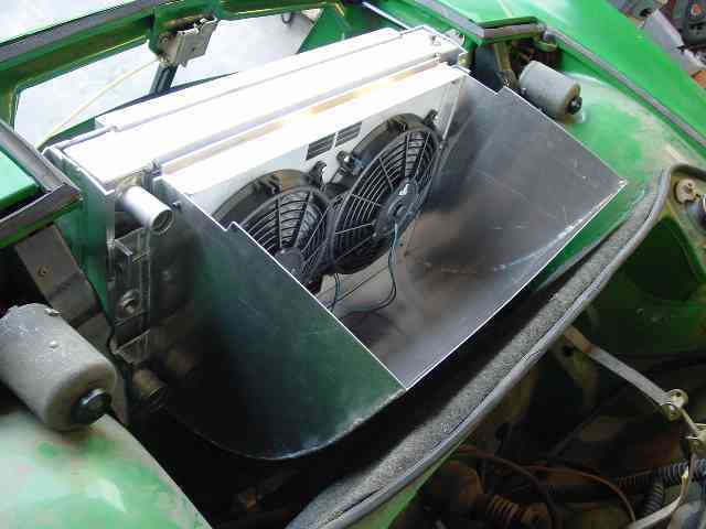
Posted by: Aaron Cox Sep 7 2006, 06:51 PM
tony, gimme a call. bumpers are in corona....
Posted by: fat73 Sep 7 2006, 08:59 PM
Alright, don't worry too much. Sounds like you are going through all the same crap as I did. You are at the end of the forrest, all you have to do is step out of it (so to speak). I know it is frustrating... but aside from your cooling issues, I think it is something small like a MAP or MAF sensor that is screwed up or something small like that. Your ECU will tell you all of your issues. If you simply can not get it figured out, do what I did and call Crawford and be driving it home in a week.
Bust ass on this Tony! Hopefully your cooling issues are all ironed out soon.
Keith
Keith...did you happen to use SmallCar's harness conversion or was it a do-it-to-youself?
Ed
Posted by: TonyAKAVW Sep 8 2006, 01:08 AM
Tonight I picked up the bumpers at Aaron's place. Got a ride in the beast, and WOW. That's a 914!!! The suspension is awesome, the engine sounds great, hauls ass, etc. The array of headlights is truly impressive. Those rally lights are like laser beams.
Got home at 11:30, so no time to try messing with the bumpers or anything else for that matter.
First off, pictures of the modified engine bay lid complete with fans. This lid and fan wiring is far from finished, but it is for the moment functional which is really the most important part as I figure out the cooling system.
For instance I haven't had time to flatten out the second grill section....
Attached image(s)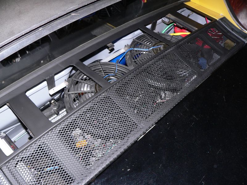
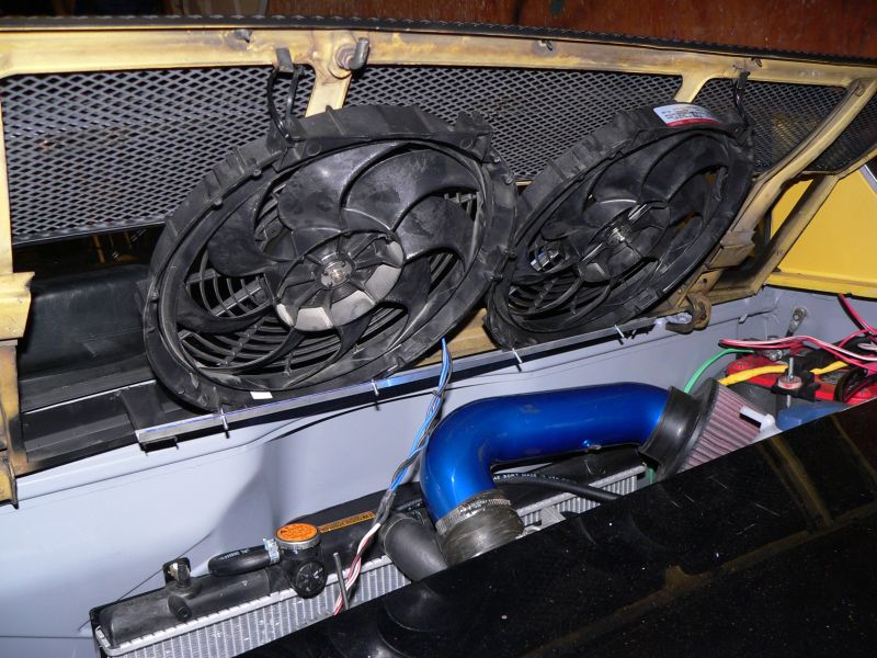
Posted by: TonyAKAVW Sep 8 2006, 01:12 AM
And now the awesome Getty bumpers. These are some fine piees of work. Haven't test fitted them yet, but they are really really well made.
One issue I need to resolve quickly is how to attach the brackets to the bumpers. The bumpers each came with a pair of fiberglass pieces made for attaching to the car, but I'm not certain how to attach these to the bumper with enough stength. Any thoughts?
Attached image(s)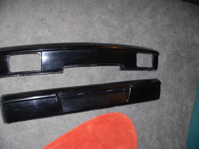
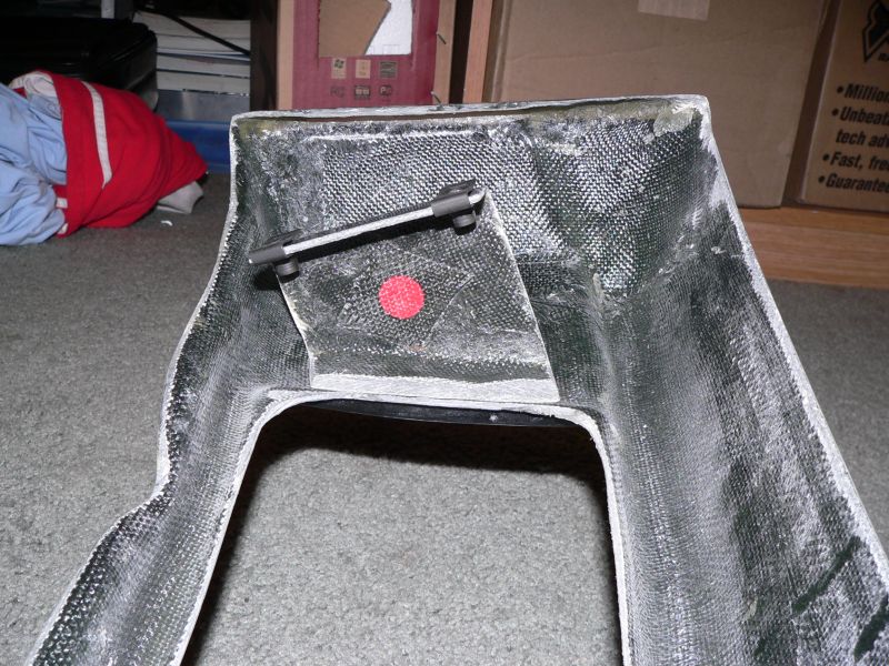
Posted by: TonyAKAVW Sep 8 2006, 01:13 AM
Lastly, more detail of the part that needs attaching to the bumper.
Attached image(s)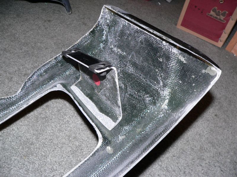
Posted by: db9146 Sep 8 2006, 10:43 PM
Here's an idea you can consider. Bolt the brackets to the car so that they are properly located. Then put some bondo (small amount) on the front of the brackets where they meet the back of the bumper and position the bumper (hold it in place with heavy tape, etc.) until the bondo sets. Then, take the brackets loose and fiberglass over the bracket/bumper joint to further strengthen it once the bondo dries.
Just a thought.
Posted by: Aaron Cox Sep 8 2006, 11:27 PM
my suggestion was do the same with JBweld and go glass it in later.....
Posted by: messix Sep 8 2006, 11:34 PM
mount the bracket, put bumper in place then drill two holes each side through bumper and bracket, put wood screws in to hold bumper and bracket, then remove bumper and bracket together, then bond the bracket and bumper together off the car, both surface between bracket and bumper and over bracket and bumper, remove screws and fill holes.
Posted by: TonyAKAVW Sep 10 2006, 02:18 AM
Big thanks to Jeff (Jkeyzer) and Royce (Bondo) who drove down today to help me finish up the car. We finished mounting the bumpers and Jeff fabricated and installed a flap in front of the radiator to attempt to create a low pressure zone at the radiator exhaust.
I gave them both noisy rides around the neighborhood and the cooling system worked fine. Jeff noted that the best part of the exhaust on this car is that at idle it purrs like any normal car, but then when you step on it, its like a racecar. Both commented that they could hear it blocks away.
Hopefully it makes it tomorrow. I need to test it on 405 first, and then I'll make a decision as to whether I drive it, or not.
-Tony
Posted by: TonyAKAVW Sep 10 2006, 07:28 PM
This morning I took the car onto the freeway for the first time. After warming up, the temperature creeped up to 225 or so and I decided to abort. It was early morning, I had gone maybe 5 miles on the freeway, and I figured it was not going to work out. So there is much work to be done yet before it it highway worthy, but think I'll be able to work it out.
Also figured out my VSS problem. First, I'm only getting 3 volts back from the sender. Second, I have two magnets on my CV joint, and this Hll sensor that I am using is a latching type, where the output goes high for one magnetic polarity, and then low when a magnetic field of opposite polarity crosses the sensor. Since I have one magnet of each polarity, I am getting just one complete pulse per revolution. Per section 2-7 of the Impreza factory service manual, the correct input to the ECU is 4 pulses per revolution of the front differential. So this means I need to unglue one of my magnets and glue on a total of eight to give me the correct number of pulses.
So the question remains... is it the low voltage or the incorrect number of pulses? If the ECU gets too few pulses, will that cause it to think something is wrong because I never go fast? Or will it just think I'm going slow and not care? For the voltage issue, it could be that the logic-high threshold on the ECU input is set above 3 volts. In all electronic systems I've run across, 3 volts should be enough to trigger a logic-high in a 5 volt logic system. However it could be that for noise immunity they keep the threshold higher. Either way, experimentation of one, then the other will tell me which it is.
For cooling, it is time to start going through the list of techniques previously posted. First up is a small lip behind the targa bar.
According to T H O M A S, (who spoke with the owner of this car), the addition of this tiny spoiler cooled his 6 cyl Porsche engine by 30 degrees!
(photo taken at 2001 German Autofest)
-Tony
Attached image(s)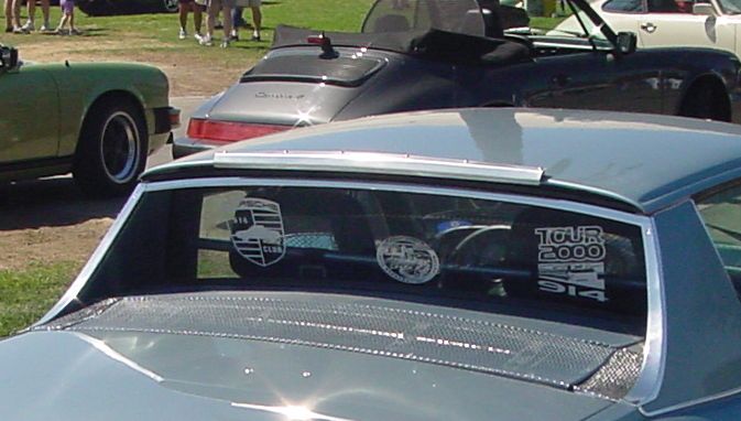
Posted by: Aaron Cox Sep 10 2006, 07:33 PM
bummer tony....
i guess just drop the G for the renegade proven system.... and go flog the crap outta it.
i musta missed you at GAF
Posted by: TonyAKAVW Sep 10 2006, 07:38 PM
I will tell you why later, but I will NEVER buy a single thing from Renegade Hybrids. Not after what happened today. Nor will I ever reccomend them to anyone else.
-Tony
Posted by: Aaron Cox Sep 10 2006, 07:41 PM
what???
PM me -
Posted by: Sideways Sep 10 2006, 07:55 PM
Torny,
Apart from the mounting brackets, how was the fit and finish on the getty bumpers?
Posted by: TonyAKAVW Sep 10 2006, 08:15 PM
The finish of the bumpers was quite good. I haven't ever bought fiberglass parts before so I don't really have anything to compare with. The gelcoat finish was really nice, almost ready to get paint.
The rear bumper required justa tiny bit of trimming to get it on. I used a copign saw, a file and some sand paper to fix it.
Royce (Bondo) shimmed the rear brackets slightly to fit, but otherwise it went together fine.
I'm very pleased with the bumpers, I think they are really a good value.
-Tony
Posted by: Aaron Cox Sep 10 2006, 08:41 PM
how did you glass the brackets on? pics? how did the boat style porthole exhaust workout?
AA
Posted by: TonyAKAVW Sep 10 2006, 08:57 PM
I didn't take any pics of the bumper process, but Royce did. He's going to post them here isn't he
To install the bumpers, we bolted the brackets to the car, sanded both mating surfaces, and used some 2-ton epoxy to hold the bumpers in place temporarily. We then taped the bumpers to the car in the correct posisiton and let the epoxy cure. After a few hours we took the bumpers off the car, and layed some pieces of fiberglass over the joints, slathered with epoxy resin. Royce noted that epoxy resin is prefered over polyester based resins, beacuse it doesn't shrink as much. Its harder to find, but one of the benefits of living in LA is that a fwe miles down the road is Plastic Depot, conveniently open on Saturday mornings. They even had carbon fiber in stock. mmmm. carbon fiber.
Anyway, after the reinforcements cured, I bolted them back up to the car. The exhaust holes haven't yet been cut. Along with the cooling and electronics tweaking, thats one of the last major things to finish.
-Tony
Posted by: Aaron Cox Sep 10 2006, 10:43 PM
badass tony. sounds like you are well on your way to being finished....
Posted by: bondo Sep 11 2006, 09:34 PM
Ok, here are some pictures!
Attached image(s)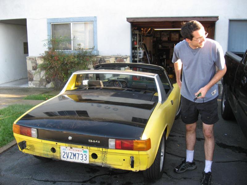
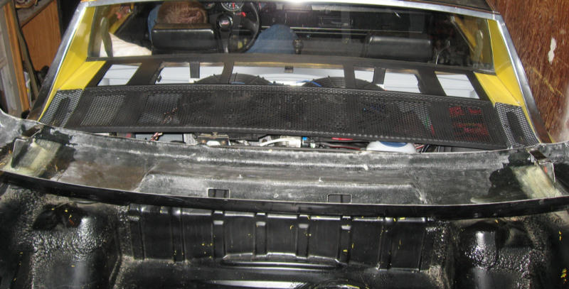
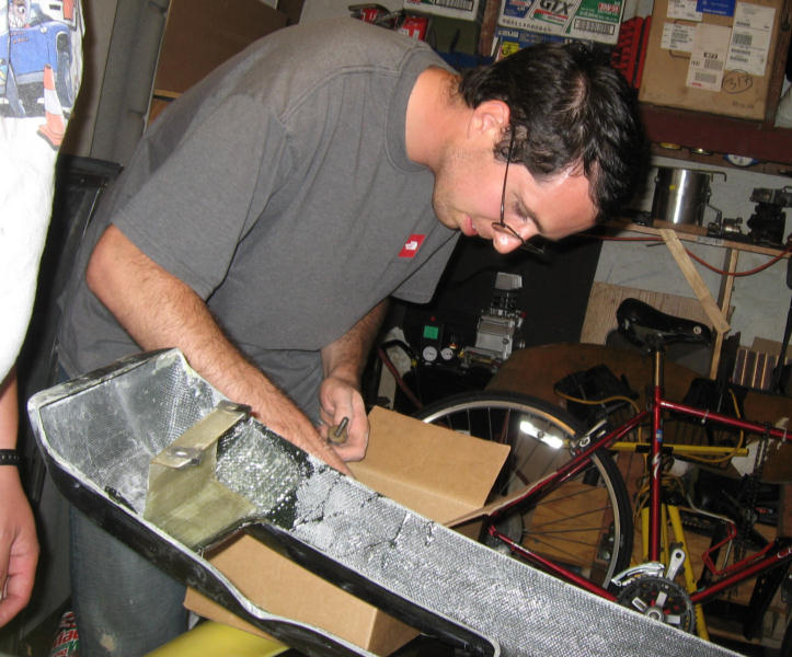
Posted by: Travis Neff Sep 11 2006, 10:15 PM
What about Scott Thacker's bottom scoop method? It sounded like he didn't have cooling issues, but I don't know if he had a temp gauge or not.
Posted by: pfierb Sep 12 2006, 04:35 AM
Tony if your avatar is a picture of you there is a picture of you in the Sunday New York Times with a story about blogs,that I didn't get a chance to read.
Paul F.
Posted by: TonyAKAVW Sep 12 2006, 11:41 AM
No, the avatar is not me... thats Napoleon Dynamite from the movie of the same name.
Regarding the direction of cooling... Scott Thatcher uses a scoop under his car and pulls the air through the radiator and up out through the engine bay lid. He made it from Massachustes (I believe) to California and back last year during spring, along with a pretty decent beating at Willow Springs and had no cooling issues.
I'm trying a different approach. I want to have as little as possible (ideally nothing) hanging below the car. To do that I have to draw the air from above the car and out under. Getting that airflow to happen is challenging because of the low pressure zone created behind the targa bar. It is however the direction of airflow that the OEM engines used. As well, it eliminates picking up hot air off the asphault. For now I have sufficient cooling for driving on streets with 4 fans (2 on the engine bay lid and two on the radiator).
However when I take it on the freeway, that low pressure zone seems to be causing me problems. To fix this I am planning on adding a small spoiler behind the targa bar that will shoot air down into the engine bay. Secondly, on the bottom of the car I'm going to fabricate a large diffuser which should help to suck air through the radiator.
I really don't know if all of this will work, but its something that hasn't been done before and if it does work would be yet another option for conversions.
-Tony
Posted by: Dr Evil Sep 12 2006, 11:44 AM
More fans, more fans! 
You remind me of the professor off of South Park, " I have created the perfect 914 with 4 asses. That 914 has only one ass, it is of no use to me.."
Posted by: project-914 Sep 13 2006, 09:40 PM
haha ^^ that's awesome
also, how about some more pics! hehe
Posted by: Crazyhippy Sep 13 2006, 09:53 PM
how about reversing the fans on the freeway?? Let the low pressure work for you when it is there, and draw cool air from above @ low speeds???
Doesn't cost anything to try it
BJH
Posted by: neo914-6 Sep 13 2006, 10:51 PM
I'm trying a different approach. I want to have as little as possible (ideally nothing) hanging below the car. To do that I have to draw the air from above the car and out under. Getting that airflow to happen is challenging because of the low pressure zone created behind the targa bar. It is however the direction of airflow that the OEM engines used. As well, it eliminates picking up hot air off the asphault. For now I have sufficient cooling for driving on streets with 4 fans (2 on the engine bay lid and two on the radiator).
-Tony
Hey Tony, I am incorporating a roof scoop to break up the flatness of the top. It works well on coupes (Exige) but a challenge on targa cars. A flap will divert the air down when needed and straight through when not...at least that's my "functional" excuse
Posted by: fat73 Sep 14 2006, 09:02 AM
Tony....
I don't if you've thought of this yet, but have you tried running any of the super coolant additive stuff in your radiator fluid. I don't remember which one it was but I know one guy I talked to at Napa a couple of weeks ago that has a turbo'd Acura that's not close to stock who say's the stuff he uses dropped the coolant temp by 28 degrees.
fyi..jacked the car WAY up and rolled the engine into the engine bay last night. Trying to mount 'er up tonight.
Ed aka fat73 and a few jacks away from W9R1
Posted by: Spoke Sep 14 2006, 09:28 AM
Tony,
Very nice job on your conversion. You'll get through the issues. Remember that technical difficulties are something that engineers purposely design into everything made in this world so we need more engineers to figure out the issues.
A question about your cooling issues. Is the overheating due to recirculating the hot air from one side of the radiator to the other? I guess this is why the air cooled engines have the tin and gaskets to keep the hot air from re-entering the cooling system.
Before my red 914 was wrecked, I was going to follow your lead on conversion. I like the placement of the radiator in the engine compartment. Now with the green 914, I'm not sure which direction to go for more power: Suby, Massive IV, or 6.
Spoke
Posted by: TonyAKAVW Sep 14 2006, 10:48 AM
BJ: I have thought about doing a reverse fan test. From the experience of the two others (Scott Thacher and Evan) with engine bay radiators, a scoop is necessary on the highway. It would be an interesting test though. A test that Bondo mentioned was to leave the engine bay fans (not the radiator fans) unplugged and put a volt meter on them to see which way the air naturally goes.
Felix: I'd like to see what kind of scoop ideas you have. I've been thinking of using some kind of scoop like racecars use (opening near the windshield, and a tunnel that goes back) or just a simple fin spanning the width of the roof, just behind it.
Ed: I think you might be talking about this stuff: http://www.evanscooling.com/main27.htm
??? Congrats on the engine-in-car. Its the first major step. Firing it up is even more satisfying. Moreso than the first drive even.
Spoke: I don't believe the problem is recirculation of hot air, but insufficient flow of cool air. I don't think that the radiator exhaust is feeding back on itself, but I think the only air getting to the radiator at high speed is warmed already by a combination of radiative engine and exhaust heat, and maybe a little blowback from the radiator exhaust. What I really need is a good pressure differential across the radiator. At speed I need positive pressure on the input side, and a vacuum on the output. A leading edge flap and diffuser are my tentative solutions for generating a low pressure zone, and a lip/air deflector above the engine bay is my idea for the positive pressure side. The diffuser will aid in isolating the air pressure from above and below the car as well. (the above is pure theory)
-Tony
Posted by: Rotary'14 Sep 14 2006, 01:36 PM
I think Ed means Redline water wetter. I've used the stuff in my conversion and I have had a similiar experieance with around a 20 degree drop in temp. It used to cost $6 but now it's more like $10 for a bottle. I have even seen it at pepboys. You should try some Tony,,,,
-Rob
Posted by: JPB Sep 14 2006, 01:48 PM
I think you can also get some air flow from the sides of the car if you scoop it. Sail panel scoops would look cool but if you want it to stay stock looking, it would compromise that. Perhaps like a Testarosa with the door skins knocked in for that purpose, there is much room in the rear fenders behind the doors for ducting.
Posted by: andys Sep 14 2006, 01:51 PM
Tony,
You being the crafty bloke you are, why don't you get yourself some vinyl tubing and make a couple of manometer columns...Two U shapes (or as many as you like) half filled with colored water zip tied to cardboard (with graduations) fastened to the dash, and run lines to areas you beilieve are the issue. This will give you an indication of where the pressure differentials are and at what speed. Duct tape and cardboard are your freinds...........You need to stop guessing. Someone needs to go through this excersize for the 914CLUB, and put to rest all the speculation. The results will surely end up in the "Classics" section.
Andys
Posted by: TonyAKAVW Oct 1 2006, 03:52 PM
I got back Thursday from Italy (gone almost two weeks) and brought with me a bad cold. Today I finally felt good enough to get some work done on the car, so I built a really cheesy spoiler to divert air from above the car to the engine bay.
Attached image(s)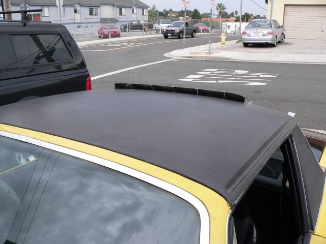
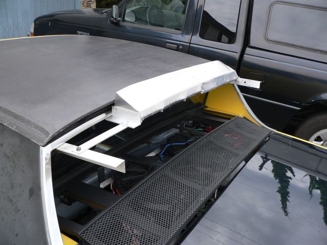
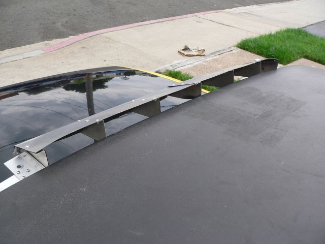
Posted by: TonyAKAVW Oct 1 2006, 04:04 PM
Testing with compressed air shows that it does effectively divert air in the correct direction. So I have some confidence that at high speeds (say above 40 mph) there is now positive pressure above the engine bay.
I took the car out for a test drive and the cooling is still not sufficient. At freeway speeds the temperature still continues to rise, very slowly, but it still rises.
My impression right now is that I am not getting a real pressure differential across the radiator other than that created by the fans, which is not enough to cool the engine. Without some kind of ducting to the radiator I will not get positive pressure on the input side. My initial design was based on creating low pressure on the output side by means of a leading edge flap (as in the rubber 914 flaps) and a diffuser/venturi. I have still not constructed these, so its possible that those two items combined with the spoiler will be enough.
However there are two other problems I have noticed.
1. The cabin of the car gets really warm. The radiator output is blowing against the firewall ad heating it up a lot. Its like a giant heater behind your back.
2. The brake lines and proportioning valve are getting heated up. This could be solved by rerouting the brake lines, but would be a bit of a pain.
So issue #1 could possibly be solved by insulation but then I'd be adding weight...
I'm beginning to think that trying to push the air from the top to the bottom just isn't going to work. There isn't enough room to put ducting on the radiator unless I move the fans to the opposite side of the radiator. If I do this I still only have a small area for ducting (maybe 2 inches of clearance before I hit the alternator or crank pulley). Then I need to get air into the ducting which could mean a huge ugly enclosed area behind the rear windshield.
So my main concern with the scoop under the car is speed bumps, but I have come up with a possbile solution...
-tony
Posted by: neo914-6 Oct 1 2006, 04:20 PM
Sorry to hear you got sick, I lost several days productivity when I was sick..
Did Jes get sick too, how was Italy?
I found a diverter online similar to your proto.
I bought a roof scoop but probably won't use it. I'd have to cut into the targa band, figure a way to duct the air into the engine compartment and make it all weatherproof. I was brainstorming with a friend the other day and a retractible snorkel sounded interesting... 
...yeah we were drinking 
Attached image(s)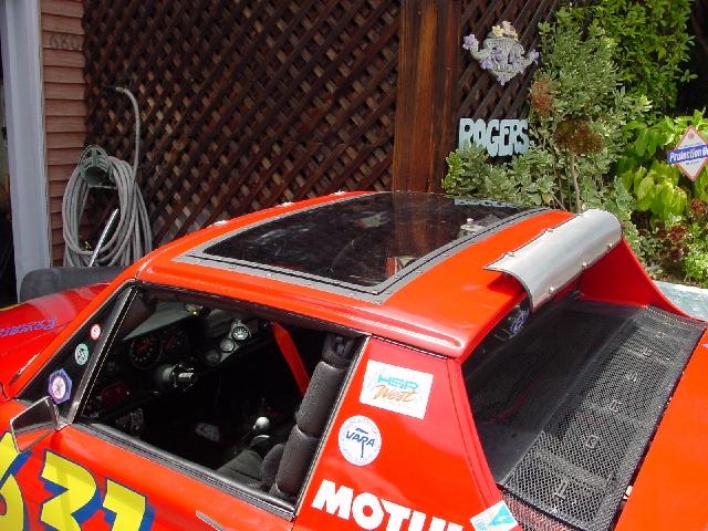
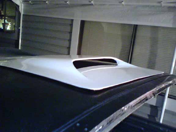
Posted by: Aaron Cox Oct 1 2006, 05:38 PM
tony... maybe bite the bullet and go front cooling (ram air = good)
not necessarily an off the shelf kit tho.... thought about maybe twin radiators like a 996 or maybe a third one in the middle like a boxster S and TT 996's?
would look just like an oil cooler (middle one) and maybe duct the 2 outer ones into the fenderwell?
could be a slick setup... and if anyone could do it... you could
food for thought

996 third rad...
Posted by: JPB Oct 1 2006, 06:59 PM
Shazzamm!
BBBBBBbeer cold.
Posted by: neo914-6 Oct 1 2006, 08:45 PM
tony... maybe bite the bullet and go front cooling (ram air = good)
not necessarily an off the shelf kit tho.... thought about maybe twin radiators like a 996 or maybe a third one in the middle like a boxster S and TT 996's?
would look just like an oil cooler (middle one) and maybe duct the 2 outer ones into the fenderwell?
could be a slick setup... and if anyone could do it... you could
DONE, and there is NO room in the fender for these
 ,
, I thinkTony will make his design work!
Attached image(s)
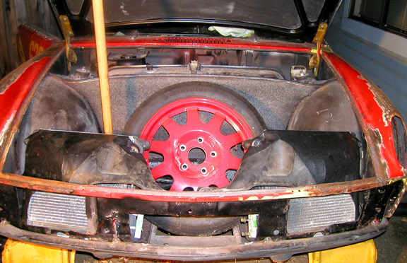
Posted by: Crazyhippy Oct 1 2006, 09:42 PM
Reverse the wires on the damned fans.... Let the cars aero help you.
It will NOT make anything worse, and will probably help alot for a whopping $0.00 investment.
BJH
Posted by: Aaron Cox Oct 1 2006, 09:52 PM
more pics felix!
Posted by: scott thacher Oct 1 2006, 10:31 PM
well tony, you have a pm.
and 1 thought might be to put a small reverse scoop under the raditaor, to get some suction going at speed, use the air flow under the car to help pull the air out
and i am still alive
scott
Posted by: neo914-6 Oct 2 2006, 12:14 PM
more pics felix!
I've high jacked Tony's thread enough.
Besides my daughter broke my camera so all I got is crappy camera pics. See it all in 30 days for the "reveal".
Posted by: jsteele22 Oct 2 2006, 05:15 PM
Glad to hear you're still alive, scott. Nobody else around here seems interested in Subaru stuff
Tony, hope you had as much fun in Italy as I envied you for. Bummer about getting sick.
About the exhaust, I think it's gonna be tough to overcome the tendency of air to want to push up from below. One way to check this, now that somebody has a tin-less driveable 914, might be to tie some (10 or so) little pieces of light thread about 4-6" long to the mesh of the engine lid. At highway speed, I'm guessing they should be waving around in circles but pointing generally up. Or you could just pour some oil on your exhaust and watch where the smoke goes.....
Posted by: ThinAir914 Oct 2 2006, 10:53 PM
Or you could just pour some oil on your exhaust and watch where the smoke goes.....
Purposely burning oil in a 914 - now there's something that's never been done before!

Posted by: TonyAKAVW Oct 3 2006, 10:35 AM
Looks liek I'm going to try reversing my airflow
Okay here's an idea for a scoop. I'm not going to implement this one right away, but eventually this might be a good way to have a scoop and avoid speedbump related death.
Basically the three blue bars slide over the speed bump and push the scoop out of the way.
-Tony
Attached image(s)
Posted by: KaptKaos Oct 3 2006, 10:51 AM
I know it's cheesy, but would an NACA duct in a location similar to this be effective? I don't know if this would be helpful or not, just throwing out ideas.
Oh, welcome back too.
Attached image(s)
Posted by: andys Oct 3 2006, 10:57 AM
Looks liek I'm going to try reversing my airflow
Okay here's an idea for a scoop. I'm not going to implement this one right away, but eventually this might be a good way to have a scoop and avoid speedbump related death.
Basically the three blue bars slide over the speed bump and push the scoop out of the way.
-Tony
Tony,
With that design you might want to remove the reverse gear in the trans
Andys
Posted by: andys Oct 3 2006, 11:56 AM
Tony,
I couldn't find the site that had a very good tech discussion regarding air flow. This one's not bad for fundamentals of cooling, but a little short on air flow:
http://www.hypertec.ws/todd_porsche/cooling/index.html
In my opinion (nag, nag, nag), you need to get that negative side establised, rather than chase the intake side. Once you get negative pressure, it will suck the air from nearly anywhere. It is far more difficult to force the air flow in a direction it doesn't want to go, as it will simply flow around it if there is any resistance.
Andys
Posted by: jsteele22 Oct 3 2006, 03:28 PM
Looks liek I'm going to try reversing my airflow
Okay here's an idea for a scoop. I'm not going to implement this one right away, but eventually this might be a good way to have a scoop and avoid speedbump related death.
Basically the three blue bars slide over the speed bump and push the scoop out of the way.
-Tony
This might be getting a bit Rube Goldberg, but that assembly could be held in the retracted position by some weak springs. At speed, it will be pushed downwards by the air flow (equal and opposite reaction...) and then if you hit a speed bump you'd have other things to worry about.
Posted by: Twystd1 Oct 3 2006, 03:37 PM
have you ever gone to davis cooling and looked at their coolant?
It works WAY BETTER than straight water and better than mix.
It may help some. This doesn't effect air flow.. I know that.
yet I am thinking it might help the system. We`used to run it on our dirt cars. We did this so we could run two row radiators( light) VS 4 row radiators. (heavy)
Worked like a charm. And the newer stuff isn't flammable.
Just a thought.
C
Posted by: Aaron Cox Oct 3 2006, 03:40 PM
how do offroad pre-runner race trucks stay cool (some are 700+hp) with a radiator in the area behind the cab...?
i know they run a monster 16" fan on em... but are they onto something?
i dont think they are ducted but could be wrong...
Posted by: TonyAKAVW Oct 9 2006, 12:18 PM
Cooling update:
Last week I took the scoop that I had made for the roof, and put it on the bottom of the car. It's not a great fit, and there are lots of cracks and holes, but its there and it does work.
I also reversed the cooling fans so they now pull air through the radiator from beneath the car. Additionally I wired the larger of the two fans to be on all the time.
The result is that Saturday I drove to Joe's BBQ (about 30 miles). The temperature slowly crept up as I drove but stabilized at about 205 degrees F. After getting off the freeway, and driving on side-streets to Joe's, it just touched 210.
I have gone over several speed bumps and curbs, including a really large speed bump in a parking lot, eith no problems. The scoop extends about 2 inches from the floor of the car.
This week I'm going to try to get the vehicle speed sensor problem fixed once and for all, and then I'll start working on a better scoop and sealing up all the holes where the cold air is getting out.
-Tony
Posted by: horizontally-opposed Oct 9 2006, 01:04 PM
Cooling update:
Last week I took the scoop that I had made for the roof, and put it on the bottom of the car. It's not a great fit, and there are lots of cracks and holes, but its there and it does work.
I also reversed the cooling fans so they now pull air through the radiator from beneath the car. Additionally I wired the larger of the two fans to be on all the time.
The result is that Saturday I drove to Joe's BBQ (about 30 miles). The temperature slowly crept up as I drove but stabilized at about 205 degrees F. After getting off the freeway, and driving on side-streets to Joe's, it just touched 210.
I have gone over several speed bumps and curbs, including a really large speed bump in a parking lot, eith no problems. The scoop extends about 2 inches from the floor of the car.
This week I'm going to try to get the vehicle speed sensor problem fixed once and for all, and then I'll start working on a better scoop and sealing up all the holes where the cold air is getting out.
-Tony
Don't know if this would be an option, but have always thought the back 1/3 of the side valance panels could have a slick scoop or NACA duct added as there is nothing behind them, or at least space for a creative duct or hoses.
This area is VERY effective — to the point that Porsche said it would have used it for the Boxster except for its one disadvantage in picking up crap from the road. Ruf uses it on their 987-based RK coupe and spyder and it provides enough intake air for 440-horsepower....
And, because the area is black anyway, it would hide the scoops. I suppose that some way of protecting the scoops from blockage would be needed, however.
Just a thought...
pete
Posted by: jsteele22 Oct 9 2006, 01:38 PM
Sounds good, Tony.
I've been toying with the idea of one of http://store.summitracing.com/partdetail.asp?autofilter=1∂=DER%2D13224&N=700+4294924500+4294839034+4294888847+4294906626+4294782793+115&autoview=sku in case I need just a little bit more cooling. It's made to cool tranny fluid; I don't know if there's a problem using it for engine oil, though. They come in various lengths, and they are small enmough that I imagine they could fit somewhere on the bottom side of a teener.
Posted by: Dr Evil Oct 9 2006, 01:46 PM
Sounds good, Tony.
I've been toying with the idea of one of http://store.summitracing.com/partdetail.asp?autofilter=1∂=DER%2D13224&N=700+4294924500+4294839034+4294888847+4294906626+4294782793+115&autoview=sku in case I need just a little bit more cooling. It's made to cool tranny fluid; I don't know if there's a problem using it for engine oil, though. They come in various lengths, and they are small enmough that I imagine they could fit somewhere on the bottom side of a teener.
A Summit racing ball cap?
Posted by: jsteele22 Oct 9 2006, 02:20 PM
Sounds good, Tony.
I've been toying with the idea of one of http://store.summitracing.com/partdetail.asp?autofilter=1∂=DER%2D13224&N=700+4294924500+4294839034+4294888847+4294906626+4294782793+115&autoview=sku in case I need just a little bit more cooling. It's made to cool tranny fluid; I don't know if there's a problem using it for engine oil, though. They come in various lengths, and they are small enmough that I imagine they could fit somewhere on the bottom side of a teener.
A Summit racing ball cap?
Yeah, ever since I got one, I've had like zero problems with overheating...
But, uh, I meant to link to item DER-13224. Dunno why it linked to that cap instead. Bet it was those damned K-Street Lobbyists...
Posted by: Dr Evil Oct 9 2006, 02:26 PM
Ah, I see. Looks good. If you consider that some of the smaller engined 911s had the trombone cooler and it worked well enough, this little gem should cool oil quite nicely. Not sure about water, though.
Posted by: spunone Oct 9 2006, 02:45 PM
Don't know about a hinge thing on bottom of car may get a little to much Grit on it and no workie...Just my .02
Posted by: Crazyhippy Oct 9 2006, 04:27 PM
how'd the car do on the drive home???
BJH
Posted by: TonyAKAVW Oct 9 2006, 04:30 PM
how'd the car do on the drive home???
BJH
Drive home was fine. Stayed below 210 the whole time. It drove a bit faster on the way home. That may have helped slightly. I could defintiely go for a taller 5th gear.
-Tony
Posted by: Crazyhippy Oct 9 2006, 04:40 PM
me too...
amazing what a little torque will do for you gearing choices
BJH
Posted by: Aaron Cox Oct 9 2006, 06:36 PM
talk to me about what ratios you want.....
a flipped H will cost ~400 ish
i can find em for ya....
Posted by: fat73 Oct 9 2006, 07:12 PM
I was at Dave White Autosports in Tampa today getting the corner balance and alignment done, and saw some pictures of a 914 that had scoops cut into the targa sails. Essentially the outside was cut in front, top and bottom, and pushed out, bent down on top and bottom to form the scoop and fabricated in, and on the inside it was cut and pushed out to meet the outside scoop. According to the guy that did it, he felt it even made the top stronger. Anyway, thinking of doing this for some intercooler flow, but so far mycar hasn't been past 190 in Tampa weather in heavy traffic (renegade w/Ron Davis front radiator). Stays around 180 most of the time.
Ed aka W9R1
Posted by: dmenche914 Oct 13 2006, 03:52 AM
Any photos of the best so far radiator/scoop arrangements to post?
i want ot redo a V6 radiator system, and would like to retain the front trunk. My thought is two smaller radiator on either side of the motor, set horizontally, with fans to help air flow up and out. Might get a bit warm however in stop and go traffic, with the exhaust pre-heated are being blown ontot he radiator from below, probably less of an issue at speed. any thought on that? The V6 is too long a motor to allow a radiator in front of the motor like the subaru motor.
Might try a raised up engine lid grill, to get the radiator higher up, which will aloow a thicker radiator.
Any thought on this?
By the way, very nice looking project so far!
Posted by: TonyAKAVW Oct 13 2006, 10:36 AM
I don't personally know what the cooling requirements are for a V6, though I encourage you to experiment. From experience I can tell you that you will need some kind of pressure-inducing element, either a scoop above or below the car, or sometihng to generatre low pressure on the output side of the radiator.
So however you orient the radiator(s), make sure you have space to duct some air to them.
No photos yet of the current cooling setup. Its a complete hack compared to the other stuff I've posted here, so until I get it working really really well, AND have it look halfway decent I'm not going to put up pictures.
However if you go back a bunch of pages I have numerous diagrams of how the undercar scoop idea works. The current setup is basically that..
-Tony
Posted by: scott thacher Oct 15 2006, 08:00 PM
well tony, i am glad you got it to cool, even if just marginally for now. it definatly need to fix the speed sensor thing, it get much more fun over 4500 rpm
and i am only doing this because i can ....." i told ya so ".... even thou i dont know if i did, sorry
Posted by: TonyAKAVW Oct 16 2006, 10:59 AM
I think I finally fixed my Vehicle Speed sensor. Here's the details of what I did and why I think certain things didn't work.
First off, the Subaru normally uses a magnetic reed switch that is triggered by a rotating magnet in the transmission. This signal is distributed to both the transmission control module and the ECU. In reality it isn't a signal until a voltage is applied to one end of the reed switch. This is important later...
So in my attempt to overdo things, I thought it would be nice to eliminate a mechanical part in favor of a modern semiconductor, namely a hall effect sensor. So I bought some hall effect sensors, built a tiny module with lots of overvoltage and ESD protection, etc. It was all nicely potted in silicone and protected by a small glass vial. It even had a green LED on it so for troubleshooting I could see what state it was in. (the sensor was activated by 16 alternating polarity magnets glued to the CV joint)
The Hall-effect module worked great except that it didn't work with the ECU. I had a small frequency counter and used it as a speedometer and it was quite accurate, giving about 1 Hz per mph. (this translates to 4 pulses per revolution of the wheel)
Something I discovered as I was working on this is tha tthe ECU provides a +5 on the VSS input pin, because it is expecting to see a reed switch. I had been feeding it a 5 volt square wave, which in theory should work, but I suspect the input for the VSS was designed specifically for a reed switch and is particularly sensitive.
After all this I decided to give the reed switch a try. I went to Radio Shack and bought a magnetic alarm switch and made a bracket for it. Last night I took the car out for half an hour and basically got onto and off of the freeway a bunch of times to get the engine revved up and down. No problems. Normally the ECU would have tripped the limp-home mode by that point and I would have been stuck with a 4300 rpm redline.
Eventually I want to put a hall sensor in, and I believe it will work. The problem is that the kind of hall sensor I used has additional smarts in it that were causing me problems. Namely it is a latching type hall sensor. So when a magnet of one polarity trips it, it goes into one state, until a magnet of the other polarity pulls it back down. This gives you a really nice square wave, but its apparently not what the ECU wants to see. What ought to work however is a non-latching hall sensor. When I replace my reed switch, I will use one of these.
Something I'm interested in still though is what goes on at freeway speeds. If my math is right, at 70 mph, the 16 magnets will be passing by the reed switch for 7 micro seconds each. I'm willing to bet that the reed switch doesn't even flinch. The solution to this (thanks Evan) is to make the magnet longer. I will hook up my oscilliscope to the VSS input some evening and watch the display as I'm driving to see how fast I can go before the reed switch stops closing.
-Tony
Posted by: mrdezyne Oct 16 2006, 02:25 PM
Please let us know how this works out. Exerpts of this thread are going into my "SUBIE CONVERSION BIBLE" as I know I will be needing to follow you with the same type of speed sensor. Thanks!
Posted by: jsteele22 Oct 16 2006, 02:33 PM
Something I discovered as I was working on this is tha tthe ECU provides a +5 on the VSS input pin, because it is expecting to see a reed switch. I had been feeding it a 5 volt square wave, which in theory should work, but I suspect the input for the VSS was designed specifically for a reed switch and is particularly sensitive.
Eventually I want to put a hall sensor in, and I believe it will work. The problem is that the kind of hall sensor I used has additional smarts in it that were causing me problems. Namely it is a latching type hall sensor. So when a magnet of one polarity trips it, it goes into one state, until a magnet of the other polarity pulls it back down. This gives you a really nice square wave, but its apparently not what the ECU wants to see. What ought to work however is a non-latching hall sensor. When I replace my reed switch, I will use one of these.
The sensor input of the ECU is a kind that sounds weird, but is fairly common, especially in industrial controls. Internal to the module, the input line has a resistor that connects to +5V. It's called a "pull-up" resistor, b/c when no external signal is applied no current flows through the resistor, so the input is "pulled up" to +5V also. To provide an input, you can touch the input to ground; now, a current flows from +5V thropugh the rsistor to ground and the input, being at the low end of the reistor, is also at ground. That's what the relay accomplishes.
To interface with this input, you should look for one whose output is either "open collector" or "pull-up". The latter simply adds a second pullup resistor to the system, so you will have 2 in parallel, but that's okay. But both of them contain a transitor output stage that will either pull the signal low (around 0 V) or let it get pulled high. This is the same behavior as the relay.
Actually, you could use the other common kind of output ("push-pull" or "logic" or "totem-pole"), which actually forces the line into a high or low state. The only risk is that if the output is being driven high and for some reason you touch the line to ground, you'll burn out the transitor.
I think you're right about not wanting a latched output. It is handy to have what are called "Schmidt Trigger" inputs; these are available on some sensors. This is a clever feature that prevents small noise fluctuations on a slowly rising signal from causing the switch to output tons of spurious on/off transitions as the noise goes above/below the threshold. Probably the ECU has it's own internal filter to avoid being tricked by this, but it can't hurt to be safe.
Posted by: TonyAKAVW Oct 16 2006, 02:52 PM
Sounds like you are a fellow electrical engineer
Yes I was aware of the pull-up resistor, and actually had one on the output of a CD40107 NAND buffer that I was using. I was confused because I was definitely pulling the input to ground on the off state, but and it seemed that should do the trick.
I'm still not really sure why the latching hall sensor didn't work. It could be that the pulse width was too long, maybe its duty cycle related?
Its things like these that make me want to do a Megasquirt. its nice to be able to see documentation other than 'Use this OEM Subaru part."
-Tony
Posted by: jsteele22 Oct 16 2006, 03:02 PM
Sounds like you are a fellow electrical engineer
Yes I was aware of the pull-up resistor, and actually had one on the output of a CD40107 NAND buffer that I was using. I was confused because I was definitely pulling the input to ground on the off state, but and it seemed that should do the trick.
I'm still not really sure why the latching hall sensor didn't work. It could be that the pulse width was too long, maybe its duty cycle related?
Its things like these that make me want to do a Megasquirt. its nice to be able to see documentation other than 'Use this OEM Subaru part."
-Tony
Oh, I knew you did something technical, but didn't know/forgot it was EE. Yeah, it's weird then that the latching sensor didn't work if it was making all the right transitions. Did you have alternating N/S poles passing it ? It could be that wide pulses would screw up the ECU if it had a debouncing algorithm in it.
Posted by: TonyAKAVW Oct 16 2006, 03:06 PM
Yep I had alternating poles. They are small neodymium magnets. By the way if you want to see something cool, get mixed up JB weld near rare-earth magnets. Does some cool stuff!
-Tony
Posted by: TonyAKAVW Oct 25 2006, 10:47 AM
So I finally got around to redoing my scoop. The first scoop I made (pictured along with the new, bigger scoop) was actually made for the roof and was wider than the radiator opening. The new scoop is wider still, but channels all the air down to an opening of the right size. So the new scoop is 4 feet wide and sticks down from the floorpan of the car about 2 inches. So far it doesn't scrape on our huge speed bumps in the parking lot at work, so I should be okay.
Haven't tested it on the freeway yet, but it should do a little better than the old scoop. I still have some gaps and hoels to fill in where air can leak out, but this is a much nicer scoop, and should deliver more air to the radiator.
I have no sheet metal brake, shear, or otherwise, so this was all made by hand with the help of a vice and some pieces of aluminum angle-iron stock.
(i.e. anyone can do this)
-Tony
Attached thumbnail(s)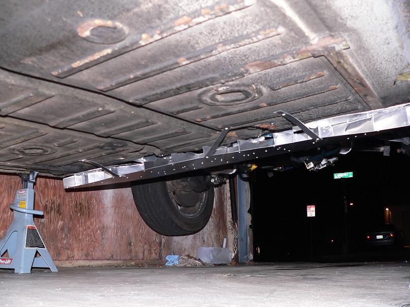
Attached image(s)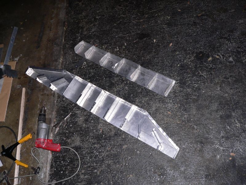
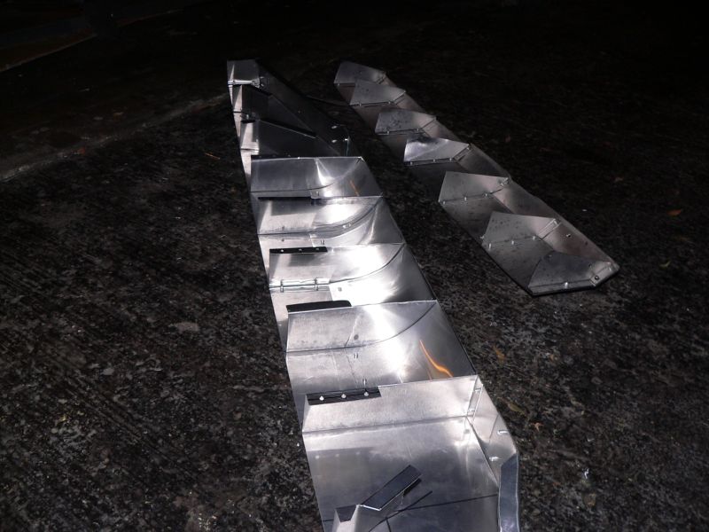
Posted by: TonyAKAVW Oct 25 2006, 10:48 AM
Here's the scoop and the associated duct-work from behind/below.
Attached image(s)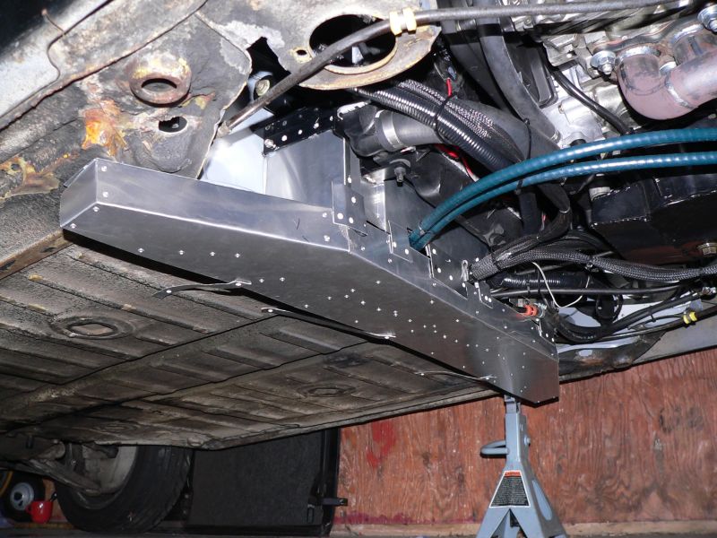
Posted by: JPB Oct 25 2006, 11:07 AM
Holly road kill collector Bat Man, I think hes gonna try to stuff us through his cooling system!!!
Now that looks AWSOME Tony. I bet this thing is gonna stay way cool now.
As for the gearing option, I am thinking of moving all my gears forward and taking out 1st. Third and fourth would be a straught shot forwards and back on the shifter but still need to find the parts for a new and improved 5th. That is, if i get an engins soon.
Posted by: dmenche914 Oct 25 2006, 07:22 PM
would a screen of some sorts be needed to prevent leaves, trash from clogging the cooling system? Me thinks this might pick up a good deal of junk off the road.
A screen would have to be fairly large in area to prevent it from getting clogged.
i have a vw powered kit car (Dino replica, Kelmark GT) with basically a rear air cooled engine,and "open" firewall to the underside. I had to install a screen on the fan intake to keep leaves out. Fan screen is common on VW's that have the engine bay metal cut away (ie dune buggies, Baja Bugs, Rails etc....)
just a thought, maybe with the air flow it won't matter.
Real nice metal work, VERY impressive with no metal brake for its construction.
Posted by: project-914 Oct 26 2006, 09:50 PM
watch out for speedbumps...don't want to mess up that beautiful work!...
nice job
Posted by: TonyAKAVW Oct 29 2006, 11:10 AM
So here's the speed bump update. In the parking lot of my workplace, we have some really serious speed bumps. When I'm in the car alone, it doesn't scrape at all. When I have a heavy passenger it grazes the top but does no damage.
I drove yesterday from Redondo Beach to San Bernardino for the autocross and the coolant temp stayed below 200 degrees the whole way out (~60 degree ambient temp). On the way home (~80-85 ambient temp) the coolant temp stayed at 210, though I was driving considerably faster. It seems that about 65 mph is the sweet spot where the cooling system works the best.
There are still a bunch of holes (some big) to patch up on this thing before I call it done, so more testing will be needed at that point. Also BJ gave me the idea yesterday of adding a rubber flap just below the opening of the scoop to help build more pressure. Definitely want to try this out.
Cooling at the autocross was a bit worse. I managed to get it up to 220 or 225 after maybe three hard runs. (this was the second session, so the car was warm to start with). So I let it sit and cool off for a bit.
Ideally I want to be able to autocross the car, drive in hot weather and not worr about coolant temps. Im going to do all I can to get the mid-radiator setup to work better, but eventually I may just have to put it up front.
This is the subject ofa nother thread, but I got the car weighed yesterday at Joe Sharp's place.
1889 lbs with no top!!!!!
1908 lbs with top on
2057 lbs with me inside, no top
-Tony
Posted by: TonyAKAVW Nov 12 2006, 01:35 AM
Some updates.
Cooling:
When I reversed the direction of the airflow I didn't reverse the direction of the fan blades. So this weekend I dug in and did that. It requires removing the alternator, air intake, top radiator hose, etc. Now that the blades are facing the right way they should be significantly more effective at providing decetn CFMs.
I installed a piece that Bondo made for me, its a billet temperature sender mount. I had been suing a sectino of galvanized steel pipe, but it had threaded ends and was leaking.
Lastly I added a bottle of Water Wetter to enhance the thermal contact of the coolant.
Clutch:
I had bought and installed a Terry clutch cable something like a year ago. It ahd no plastic sheathing and wore away at the clutch tube at the firewall. It caused me tohave to adjust the clutch cable routinely. So I took out the cable (which was very close to breaking) and bought a new GEMO cable. It ahs a full plastic sheath all the way through the tube in the car. Also I machined a small aluminum insert to go in the worn end of the tube. It has a lip on the end so it can't slip in.
Attached thumbnail(s)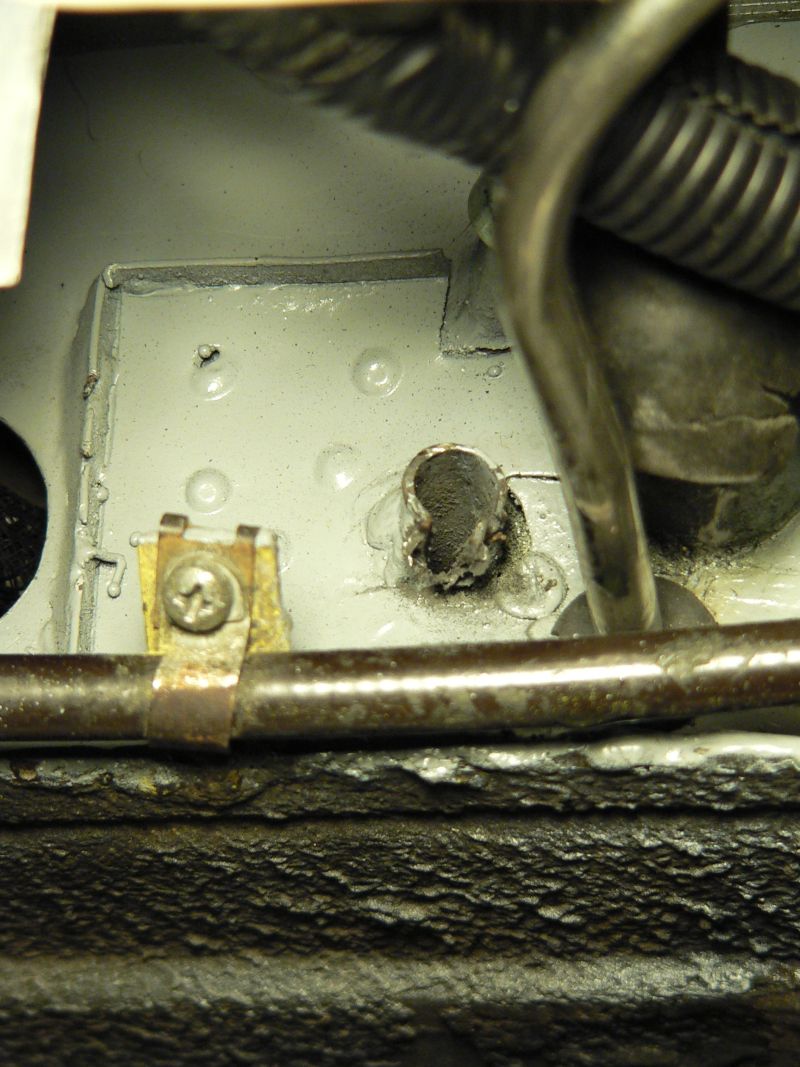
Attached image(s)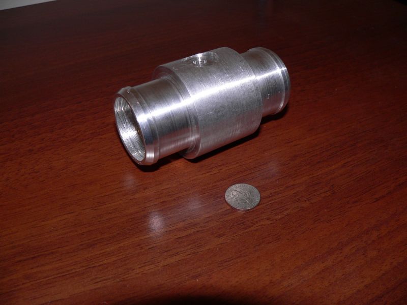
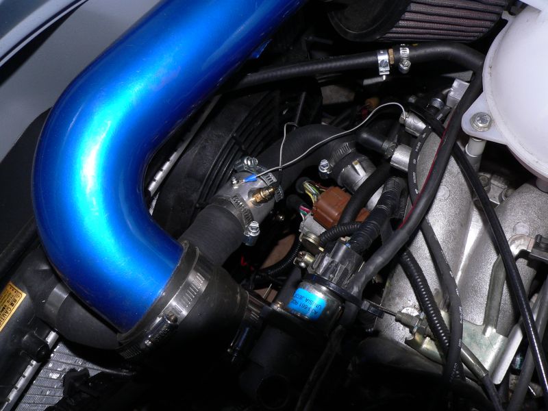
Posted by: TonyAKAVW Nov 30 2006, 12:12 PM
I started working on the center console for the conversion. With the electronics and shifter mechanism exposed, a problem was waiting to happen. Either running my knee into the corner of the aluminum structure of the shifter mount, or liquid dripping on to the ECU wiring, something was bound to happen.
So the console is made principally from 1/2 inch high density fiberboard. Its heaver than I'd like, but will be strong enough to withstand a fair amount of abuse.
The entire console will bolt on to the center tunnel by means of three pieces of angle-stock aluminum. Two of the three are in place now, the third will be at the front, in front of the shifter. I'll use sheet metal screws to fasten it to the tunnel.
The lid for this will be a combination armwrest and shifter opening. Black carpetting will line the outside of the box, with the cushioned lid covered in black vinyl to match the door panels and seats. The lid will be fastened to the box with some kind of snap-in part. I haven't figure that out yet and need to see wat McMaster Carr sells. Being able to remove the lid will allow me access to the cable shifter for adjustments and the ECU electronics.
Ahead of the console on the tunnel (near where your feet go) will be empty, and I will probably build a second piece to put there. It will likely be a small speaker box that will be removable.
The piece of blue stuff is foam rubber from a seat pad that I found at REI. The strap is also from REI and holds the ECU against the panel. I'll probalby use the same foam rubber for the armrest. Its pretty dense and easy to cut etc.
-Tony
Attached image(s)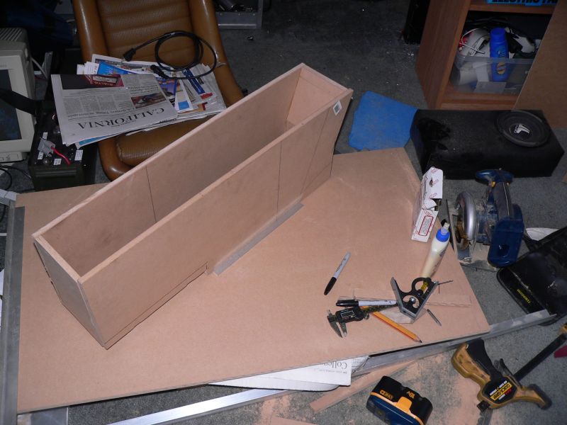
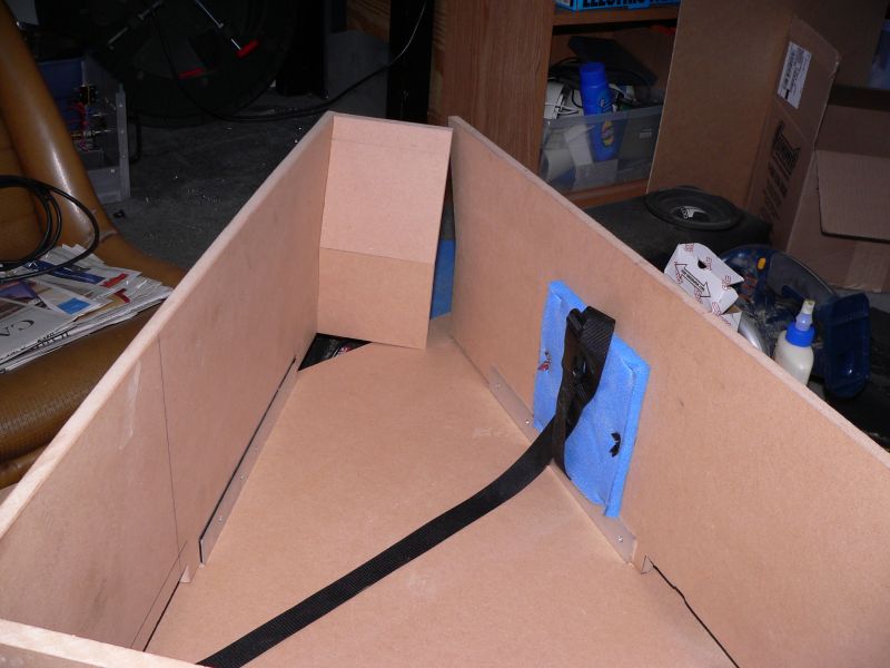
Posted by: TonyAKAVW Dec 1 2006, 02:51 AM
The console is finished. I covered the console with carpet and the lid (held on by three black screws) is upholstered in black vinyl. Under the vinyl is a layer of headliner and the raised section is the back is a piece of high density foam rubber from a sleeping pad that I bought at REI. A little 3M Super 77 and a bunch of staples and here it is.
Attached thumbnail(s)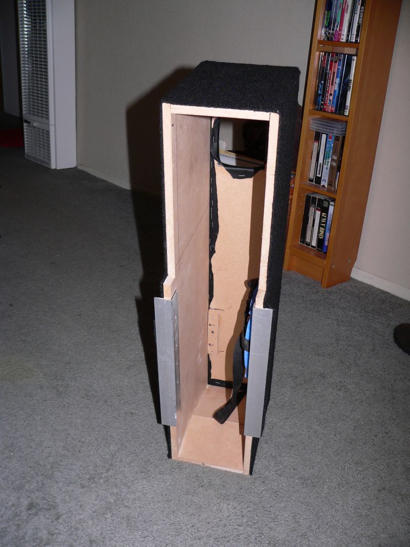
Attached image(s)
Posted by: Eric_Shea Dec 1 2006, 10:43 AM
Excellent thread Tony. Your car is awesome. That's what this club is about
Posted by: fat73 Dec 1 2006, 11:23 AM
No cup holders?!
Good work Tony (again). I'm about to do something similar for mine, but it won't encompass the shifter. You'll find that the center console idea that supports your right arm will come in handy if you ever take long road trip.
We're going to be doing a complete replacement back pad out of fiberglass so we can include some speakers and account for the roll bar. We'll probably also be doing some custom door panel armrests since the stock ones get in the way of the Autocar roll bar.
Again...you're an amazing dude.  Keep the info coming.
Ed aka W9R1
Posted by: jimkelly Jan 24 2007, 08:21 AM
this may be worth something
http://www.cycoactive.com/Urabus/default.htm
Posted by: TonyAKAVW Apr 23 2007, 01:22 PM
Its been a while, and thats mainly because I've been driving the car and enjoying it a lot! This past Saturday I swapped out the front suspension with one from a 1987 carerra SC. That means bigger brakes, an aluminum cross member, bigger torsion bars, and a bigger sway bar. In the process, the ride height is now lower and I like it! The problem is that I now get insufficient airflow under the car for the scoop. I know this because the morning I drove out to do the swap, the temp stayed under 195 and I was going up hills etc. That same evening driving home with the new, lower front end,it got several degrees hotter. Now part of that could be due to my front valence which had partially come off and blocked the airflow more, but I really want more margin on the cooling system.
First off, here's a picture of why my airflow is reduced. You can see that the scoop (aluminum piece just below the car near the back of the door) now has no line-of-sight to the airflow coming in from the front. Not good.
Second picture shows a radiator I just bought today for $75 from a local parts place. Its a radiator for a 1988 VW Jetta GL. They come in two widths, one for cars with AC, and without. One has a 675 mm core width (the one I got) and the other has a 525 mm core width. Fitment may be tight, but I'll report on that later today when I go pick it up. Its a dual pass "scirocco" style aluminum radiator with a 1.25 inch thick core. Ought to do the job fine up front.
By the way, if anyone wants to order this radiator, the place I used is called Pacific Coast Imports and they are at (310) 374-8933. Located in Hermosa Beach on PCH. I have been buying parts from them for a while now. They are very cheap, and have quite a few parts for 914s. Also, http://www.importedcarparts.com Considerably cheaper than Pelican in general.
Attached image(s)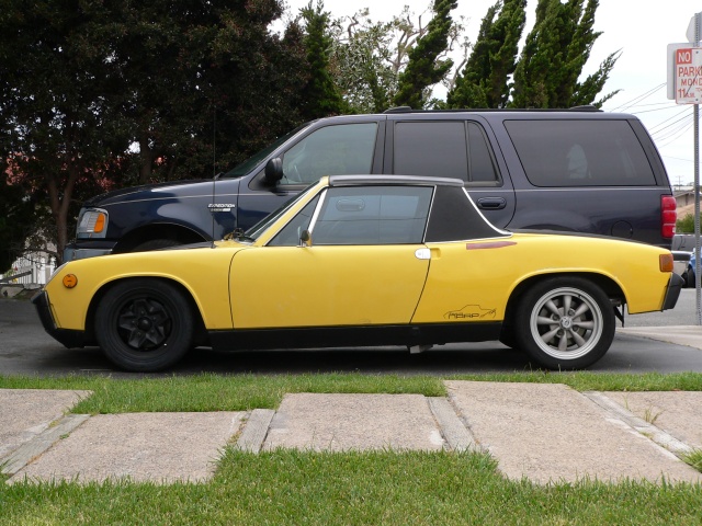
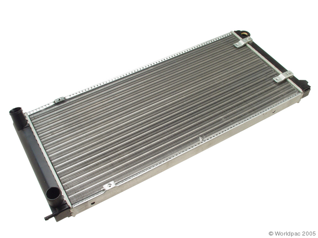
Posted by: Aaron Cox Apr 23 2007, 02:24 PM
going front radiator?
Posted by: TonyAKAVW Apr 23 2007, 02:28 PM
Yep.
Posted by: Aaron Cox Apr 23 2007, 02:33 PM
atta boy
Posted by: TonyAKAVW Apr 23 2007, 10:57 PM
Picked up the radiator today and did some fitting. Width is PERFECT. I think this really will allow me to have a usable front trunk. Compared to the stock Subaru radiator, this one is an inch shorter. It is however a dual pass and has a thicker core. Should work okay.
Attached thumbnail(s)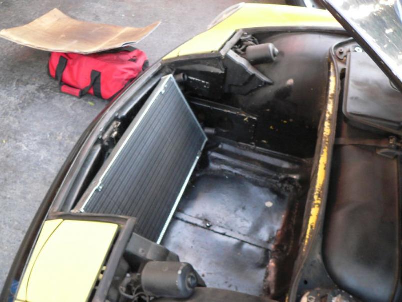
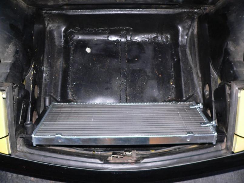
Posted by: TonyAKAVW Apr 23 2007, 10:58 PM
last
Attached thumbnail(s)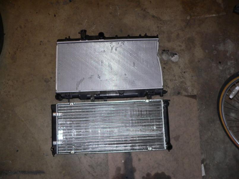
Posted by: Crazyhippy Apr 23 2007, 11:04 PM
You want to pull that back a bit. Top roughly even w/ the back of the headlight buckets, vertical if it fits, otherwise kick the bottom back till it does.
Be sure any air coming in the front HAS to go through the radiator, otherwise it wont, and you run into the same problems you have now...
Posted by: drive-ability Apr 23 2007, 11:47 PM
Tony,
Not that I disagree with Crazyhippy, but if you seal in the air inlet chamber real tight, to make sure every bit of air must pass through the radiator along with making sure your fans are shrouded just as tight you will maximize what you have. I would run 2 fans, so to allow the air have a larger path to exit the confined air chambers. I think that will help cool more effectively when the fans are off and at a cruse speed. I think with two fans your low speed cooling will be more effective. Surely you look like you know what your doing I'm just adding my 2 cents.. If it's not cooling well you can always move it back as Crazyhippy said.
Posted by: Crazyhippy Apr 24 2007, 12:06 AM
The problem w/ the rad. being that close is getting air flow across the whole radiator. You end up w/ the bottom 1/2 of the radiator getting lots of airflow, and the top getting very little. W/ it set back a bit, the pressure is closer to equalized across the whole surface, letting the whole radiator work (and if 1/2 the radiator was capable of cooling it, why pay for the full radiator?)
Why not put an air cooled motor in it and forget all this radiator nonsense?
BJH
Posted by: TonyAKAVW Apr 24 2007, 01:31 AM
That makes sense about pulling the radiator back.
I'm planning on using two fans for sure. I've got two on my current radiator setup and I may just end up using those. On the other hand I have a couple extra fans and it would be nice to have the new cooling system fully ready for a fast switchout of the old one.
So my current project then is to construct some sort of bracket, some airtight shrouding, and a shroud for the back to act as a subfloor and duct. I'll have to figure out an intersting way to do that. Also would like to try to make room for one of those 911 compact spares.
-Tony
Posted by: GS Guy Apr 24 2007, 07:00 AM
Tony - could you provide the overall width and height of that radiator? Also inlet/outlet sizes?
I've considered using that radiator for my "conversion", or a custom Afco Scirocco style (slightly wider than their off the shelf units). Obviously the OEM unit is a LOT less than an all aluminum radiator.
With proper shrouding and fans - think it'll cool a turbo motor?
Jeff
Posted by: Crazyhippy Apr 24 2007, 09:28 PM
Tony - could you provide the overall width and height of that radiator? Also inlet/outlet sizes?
I've considered using that radiator for my "conversion", or a custom Afco Scirocco style (slightly wider than their off the shelf units). Obviously the OEM unit is a LOT less than an all aluminum radiator.
With proper shrouding and fans - think it'll cool a turbo motor?
Jeff
Size wise the scirocco should cool a turbo motor in all but the most extreme weather.
When you're sitting in phoenix traffic and it's 118* out... maybe not.
BJH
Posted by: drive-ability Apr 24 2007, 10:01 PM
CrazyHippy has the right idea and you may just not have enough cooling capacity given the restricted flow. Again if you make sure all the air must pass through the unit it will give you your best shot. I would move it back and rearrange things. Really I would go with a larger unit to be sure your covered and have back up built in the cooling system, after all its a performance car and you just may
hammered a few times
Posted by: TonyAKAVW Apr 24 2007, 11:55 PM
Overall length including the nipple (which looks to be an ideal spot for bleeding out air) is 30.75 inches. The height is just under 13 inches.
I will get a real test with this radiator setup at the Lone Pine Time trials. The temperature should be in the high 90s... For the NA motor I expect it to do okay.
-Tony
Posted by: TonyAKAVW Apr 30 2007, 11:05 AM
Yesterday I took the first step in placing the radiator up front. Namely, cutting out a hole for the cold air inlet. I painted the front and inside lip of the trunk with Zero Rust partially to clean things up and partially for rust prevention.
-Tony
Attached image(s)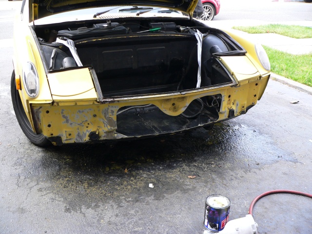
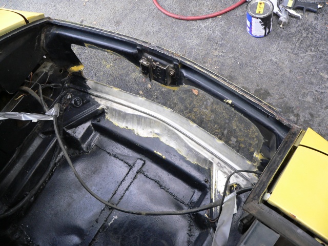
Posted by: TonyAKAVW Apr 30 2007, 11:07 AM
with paint!
Attached image(s)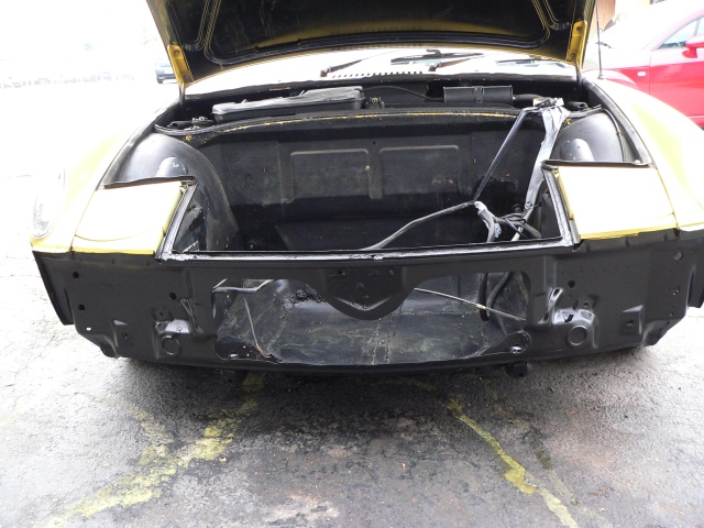
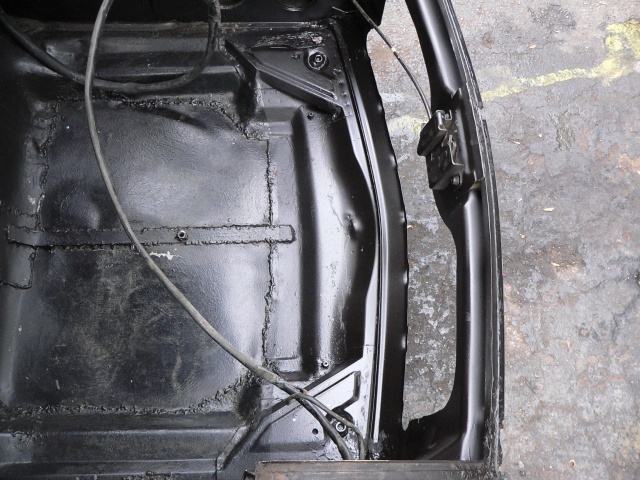
Posted by: Elliot Cannon Apr 30 2007, 12:50 PM
That's a huge inlet hole! How will the air exit?
Attached image(s)
Posted by: TonyAKAVW Apr 30 2007, 01:02 PM
I didn't get time to cut the outlet holes, but they will be on the wheel wells as is commonly done. That inlet hole is about the normal size for front radiator isntallations. I probably could have gone with less, but now I have less sheet metal weight
Now I'm trying to figure out if I want to make an aluminum shroud or a fiberglass shroud.
-Tony
Posted by: skline Apr 30 2007, 02:38 PM
I vote aluminum, all the good ones use aluminum as fiberglass is messy, it cracks, just overall not as good or strong. But that is just my opinion.
Posted by: Crazyhippy Apr 30 2007, 09:57 PM
Add a brace from the latch to the floor.... .5x.125 angle works just fine. Just something to supprot the latch.
BJH
Posted by: toon1 Apr 30 2007, 10:56 PM
I noticed you are using a cable shift setup. Is it possible to use the stock shifter setup?
I'm interested in this conversion
Posted by: Crazyhippy Apr 30 2007, 11:04 PM
Mine has a stock(ish) shifter. Had to re-make the engine bar setup so it wouldn't go through the cross exhaust pipe. Not a big deal, but takes some welding and a bit of thought.
On the NA motor, you might be able to use the factory bar if you use seperate exhaust like tony did.
BJH
Posted by: toon1 Apr 30 2007, 11:18 PM
Mine has a stock(ish) shifter. Had to re-make the engine bar setup so it wouldn't go through the cross exhaust pipe. Not a big deal, but takes some welding and a bit of thought.
On the NA motor, you might be able to use the factory bar if you use seperate exhaust like tony did.
BJH
What's the NA motor?I've been looking at the 1.8
What was the final cost of your instalall? How long did it take?
Keith
Posted by: Crazyhippy Apr 30 2007, 11:30 PM
I did a break down of my costs http://z8.invisionfree.com/ClubNARP/index.php?showtopic=951
NA is Naturally Asperated or non-turbo in the sooby world. As far as time, i could do another one in 2 weeks pretty easy. This one took just under 6weeks. Mostly relaxing evenings.
BJH
Posted by: toon1 Apr 30 2007, 11:52 PM
thought the NA was part of the serial #.
HOw does yours shift? better, worse or the same.
Posted by: Crazyhippy May 1 2007, 12:00 AM
thought the NA was part of the serial #.
HOw does yours shift? better, worse or the same.
mine shifts like a 914... GREAT w/ new bushings, but if the bushings are worn, kinda like there is a coupler made of mashed potatoes somewhere in the linkage...
Tony's should shift much more consistantly, as there are really no bushings to wear, only the cables, and they last a LOT longer if taken reasonable care of.
Posted by: toon1 May 1 2007, 12:06 AM
I went to the link and checked the costs, not bad. for the setup I have planned it's possible for about 22-2400, that's very reasonable as compared to a TIV rebuild.
Posted by: TonyAKAVW May 1 2007, 12:54 AM
My conversion cost somewhere around $3000 to $4000. It took me a lot more time to do myh conversion for the following reasons:
1. Never did one before
2. Did a ton of custom wiring and electronics
3. Fabricated the engine mount, radiator frame, scoop, etc.
4. Did a complete makeover of the engine bay
In all, mine took me really about 6 months of serious work and about 6 months prior to that getting things done very slowly.
The cable shifter works well, though not as nicely as I want. There are still several things I need to do to improve it, but I think it will eventually give me a shifter that performs very nearly to that of a modern car. Getting the improvements I want will require machining a bunch of parts, and its not at the top of my priority list at the moment.
BJ: Thanks for the tip about the latch support. I was wondering about that...
-Tony
Posted by: toon1 May 1 2007, 09:22 AM
Tony, i noticed you have the front of the car cutout for the radiator, is it installed yet? Are the mounts nd shrouds custom? where did you source the radiator?
You may have mentioned the radiator source earlier in the thread, I may have missed it.
Posted by: TonyAKAVW May 1 2007, 10:50 AM
I don't have the radiator moutned yet. I just cut the hole on Sunday, and probably won't get a chance to work on it until Friday. The mounts and shroud will be completely custom. Made with sheet aluminum and pop rivets.
The source of the radiator, price etc., are quoted on the previous page somewhere around the middle. You can find this radiator anywhere, its a pretty common one, and cheap too.
-Tony
Posted by: 914-8 May 1 2007, 12:02 PM
This is probably obvious to you, but in case it's not -
When you build your shroud, made sure that it COMPLETELY encloses and seals the radiator off, so all air coming in through your opening is forced through the radiator. And so no hot air that has already passed through the radiator can seep around the edges and get drawn in through the front again.
It makes a big difference.
Posted by: jimkelly May 1 2007, 03:55 PM
you finally caved in - good form you : )
this is one of my favorite threads - have you ever had second thoughts about using 901 trans versus using subaru trans ???
jim - got me a 1972 with sbc v8 and a 1975 with 2.0 - no sub yet : )
Posted by: TonyAKAVW May 1 2007, 04:24 PM
I have thought about using a Subaru transmission actually. I really should start thinking about it more because my 901 is going to need a rebuild soon. I think the cost of rebuilding a 901 would be higher than using a Subaru trans. I never did find out what is going on with the special axle/CV adapters though.
6 speeds might be fun
-Tony
Posted by: drive-ability May 1 2007, 04:37 PM
If I do another engine conversion and I am sure I will, I will use an engine and transmission thats a factory package, no more adapting one engine to a different make transmission. They work but not like ones made for eachother....
Posted by: Porcharu May 2 2007, 10:49 AM
I have thought about using a Subaru transmission actually. I really should start thinking about it more because my 901 is going to need a rebuild soon. I think the cost of rebuilding a 901 would be higher than using a Subaru trans. I never did find out what is going on with the special axle/CV adapters though.
6 speeds might be fun
-Tony
I'm still working on that part! I have to pester my machinist for the flanges.
Cost wise the Suby trans parts are WAY more reasonably priced than 901 parts - I just got a used helical gear LSD for about $200. New ones are in the $750 range. Close ratio gear sets start around $800 for a complete new set of gears.
Steve
Posted by: TonyAKAVW May 6 2007, 11:26 PM
So last weekend I got the front opening for the radiator cut. This Friday I cut the exhaust holes, and today/yesterday I built the radiator shroud. I ended up going with sheet aluminum. Turned out very light weight and fits nicely. It will be riveted into the car and I'll use some silicone to seal the few gaps.
Powder coated flat black.
-Tony
Attached image(s)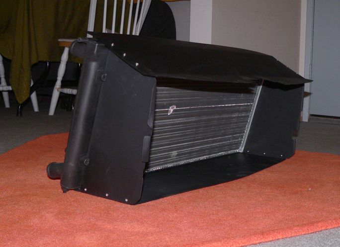
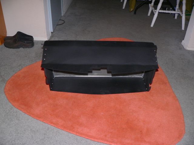
Posted by: Crazyhippy May 9 2007, 02:20 AM
Nice work...
Posted by: Aaron Cox May 9 2007, 12:28 PM
we need installed pics!
Posted by: TonyAKAVW May 9 2007, 12:34 PM
Maybe by this weekend. I've got to rivet on some angle-stock to the sides so the radiator can be held in place. Right now its just sitting there. Also have to mount the fans and run fan wires to the front.
My plan is to have this new cooling system completely ready to plug in. basically unplug the fan connector to the current system and the two hoses and conenct to the new system.
-Tony
Posted by: pankopp Jun 8 2007, 02:01 PM
so what did you ever do with the fuel pump return? did you cap it off or tee them together? I didnt see it mentioned.
Great lookin build, i am taking the easy way out with the renegade kit, now i'm just waiting for it to get to my door.
Also did anyone ever find out if you could just use the stock subaru in-tank fuel pump. I have a full 2.2 litre legacy that is my parts donor, so if i can use as many stock parts that i have, the better.
Thanks!!
pankopp
Posted by: fat73 Jun 8 2007, 03:43 PM
thought the NA was part of the serial #.
HOw does yours shift? better, worse or the same.
mine shifts like a 914... GREAT w/ new bushings, but if the bushings are worn, kinda like there is a coupler made of mashed potatoes somewhere in the linkage...
Tony's should shift much more consistantly, as there are really no bushings to wear, only the cables, and they last a LOT longer if taken reasonable care of.
If you don't want to go with the cable shifter I suggest the RennShift shifter. Makes a totally different transmission out of the 901, with no slop, if you have $475 to spare.
Also, this is the way I modified my shifter bar. It's important that you keep the geometry intact. I used the stock shifter bar to start with. Then I bought some 1/2 conduit. I decided where I needed to cut the shifter bar one spot at a time and marked the cut. BEFORE doing any cutting, using a permanent marker you draw a straight line intersecting the cut line. That way I could realign the pieces and not lose the geometry (i.e. twist the shifter bar). I inserted into each cut a small piece of the conduit, notched the conduit out and bent it using trial and error until I got the angles I needed. Then I welded up the shifter bar at each joint leaving the conduit in to help hold the angles. I believe I ended up with 4 cuts. Just make sure if you do this you weld up the shifter bar really good, otherwise it will crack on you and make you think you've lost the transmission (been there done that), making it hard to get into gear.
That way you don't end up with an ugly shifter bar that looks much different than stock, there's less guesswork, and you can keep the geometry pretty much intact.
My $.02 worth.
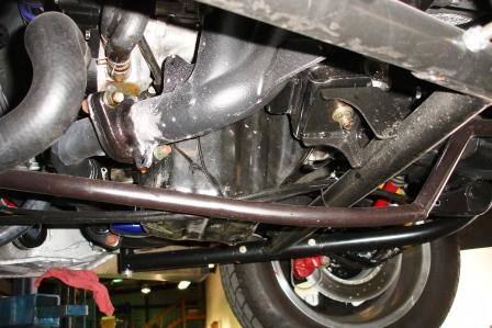
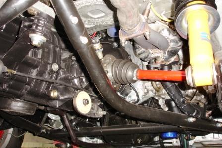
Here's my shrouding from the cutout (which looks like Tony's except that I left a strip in the middle for bracing) into the nose. I riveted in the shrouding and sealed it up with that really nasty clear silicone. I'm interested in seeing what Tony comes up with for the radiator install. I used everything Renegade had and I personally think that the Ron Davis Radiator ($1000) is overkill for the EJ20. It almost runs too cool.
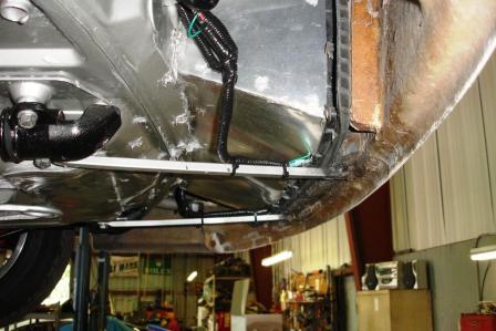
Ed aka W9R1
lots of conversion pics at community.webshots.com/user/fat73
Posted by: fat73 Jun 8 2007, 03:47 PM
So last weekend I got the front opening for the radiator cut. This Friday I cut the exhaust holes, and today/yesterday I built the radiator shroud. I ended up going with sheet aluminum. Turned out very light weight and fits nicely. It will be riveted into the car and I'll use some silicone to seal the few gaps.
Powder coated flat black.
-Tony
Awesome job.
Ed aka W9R1
Posted by: fat73 Jun 8 2007, 03:52 PM
I didn't get time to cut the outlet holes, but they will be on the wheel wells as is commonly done. That inlet hole is about the normal size for front radiator isntallations. I probably could have gone with less, but now I have less sheet metal weight
Now I'm trying to figure out if I want to make an aluminum shroud or a fiberglass shroud.
-Tony
Instead of the holes through the fender wells, has anybody gone the GT40/Ferrari F40 route and modified the hood? I think that's what I'm gonna do on the one I'm building now.
Ed aka W9R1
Posted by: Luke Jun 8 2007, 08:49 PM
Fat73 ,
How big is the Ron Davis core ? .. I'm trying to size mine right now ...
Thinking of a 13" tall 2.5 or 3" core Scirocco style for my turbo 2.0 ...
Posted by: fat73 Jun 8 2007, 09:13 PM
Fat73 ,
How big is the Ron Davis core ? .. I'm trying to size mine right now ...
Thinking of a 13" tall 2.5 or 3" core Scirocco style for my turbo 2.0 ...
It pretty much fills up the distance from the edges of the headlight buckets to almost the floor of the trunk. It actually sits on a Renegade aluminum platform that is about 3 inches high.
Here's a link to give you some idea. The radiator itself is about the thickness of the bend in the top of the shroud.
http://rides.webshots.com/photo/2122880320076795939jgizNP
Ed aka W9R1
Attached image(s)

Posted by: fat73 Jun 8 2007, 09:30 PM
Fat73 ,
How big is the Ron Davis core ? .. I'm trying to size mine right now ...
Thinking of a 13" tall 2.5 or 3" core Scirocco style for my turbo 2.0 ...
I don't want to hijack Tony's thread with my stuff, AND I suggest you take a VERY close look at what Tony's done. Excellent, excellent, excellent work. I wish he lived close to me.
I think his setup will work as good or BETTER and you won't spend nearly as much money on it.
I have a '72 that I'm going to start another thread on soon. In the mean time you can reference most of what I've done on community.webshots.com/user/fat73.
Good luck.
Ed aka W9R1
Posted by: fat73 Jun 9 2007, 08:42 AM
Fat73 ,
How big is the Ron Davis core ? .. I'm trying to size mine right now ...
Thinking of a 13" tall 2.5 or 3" core Scirocco style for my turbo 2.0 ...
One more thing you'll want to take into consideration then I'll shut up. If you're gonna run A/C in your car, the A/C condensor will have to fit in front of the radiator to get air flow on it to keep it cool, and you'll have to allow for the A/C lines to run into your shrouding. If you can get a radiator that'll fit with a condensor on it, that would be ideal. I'd suspect
stock subie condensor would be best if you can make it fit. I managed to get the stock compressor and A/C lines with my WRX Engine, so the A/C line fabricator used the ends at the A/C compressor off of the stock lines. I used Renegades condensor and dryer but then again I used the radiator setup too. Just my opinion.Ed aka W9R1
Posted by: Luke Jun 10 2007, 04:30 PM
Thanks for all the great advice ..
I wasn't sure if the stock style was enough against the turbo and the So. Cal 115º days .. especially if I do some up grading ....
Putting the AC back would sure be nice ....
And not to steal your thread either .. thats a hell of a job on the ducting Tony, can't wait to see it finished ...
Posted by: TonyAKAVW Jun 10 2007, 04:49 PM
Installed radiator.
Attached thumbnail(s)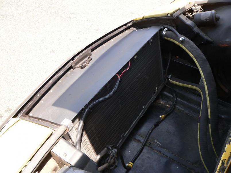
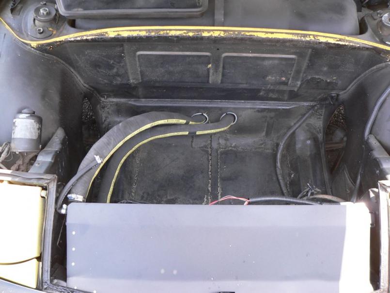
Posted by: TonyAKAVW Jun 10 2007, 04:50 PM
..
Attached thumbnail(s)
Posted by: TonyAKAVW Jun 10 2007, 04:59 PM
Next step is to fix up the front trunk area for some storage space. I want to at least be able to fit a good size set of tools in there and there seems to be plenty of room.
-Tony
Posted by: fat73 Jun 10 2007, 07:10 PM
Next step is to fix up the front trunk area for some storage space. I want to at least be able to fit a good size set of tools in there and there seems to be plenty of room.
-Tony
As usual, nice work Tony.
I wish I had more front trunk space. I wonder if a couple of sets of 90 degree elbows would be feasible to route the radiator lines over to the right and directly up to the radiator?
Hmmmm.....Probably would work.
Ed aka W9R1
Posted by: eric914 Jun 10 2007, 07:19 PM
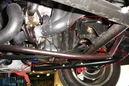
Whose motor mounts are these?
Attached image(s)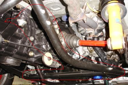
Posted by: bondo Jun 10 2007, 07:22 PM
Whose motor mounts are these?
Snicker.
Posted by: eric914 Jun 10 2007, 07:26 PM
Exactly why I ask
Posted by: fat73 Jun 10 2007, 08:33 PM
Whose motor mounts are these?
The crossbar is a Renegade unit and the mounts are actually STI mounts.
Ed aka w9R1
Posted by: pankopp Jun 11 2007, 09:07 AM
Any information on fuel Pump? I asked earlier, but you may have missed it...
Thanks!
Posted by: TonyAKAVW Jun 11 2007, 10:51 AM
I did see the question but didn't get a chance to look at it. As I recall I have a T junction in the fuel return line, one end comes from the pump, one from the fuel rail. Thats what I recall at least...
-Tony
Posted by: jsteele22 Jun 11 2007, 03:59 PM
Hey Tony,
Nice work on the radiator. Just curious : what did you use to cut the openings in the body ? Seems like the standard tool is the sawzall, but I still have a hard time imagining getting results that smooth.
Posted by: TonyAKAVW Jun 11 2007, 04:05 PM
Here's a price breakdown of my front radiator installation.
1. Radiator (dual pass, "scirocco" style, aluminum, for a late 80's Jetta) $75
2. Radiator Fans (12 inches, pusher style, bought at local electronics swap meet) $10
3. Coolant hose (bellowsflex, 1.25 inch I.D., 20 feet) $180
4. Metal to fabricate shroud $10
5. Metal to fabricate hose adapters $11
6. Misc. hose bends (taken off the engine, previous radiator install) $0
7. Hose Clamps $10
8. Clamps for hose $7
Total: $303 (or 1/3 the cost of the commercially available alternative)
Bellowsflex is almost twice as expensive as the normal stuff from Napa which is definitely as good. The radiator fans would probably cost $150 for new ones but can easily be purchased at a pick and pull for less.
-Tony
Posted by: TonyAKAVW Jun 11 2007, 04:08 PM
I used an air body saw from Harbor Freight. $19.99 on sale currently
Attached image(s)
Posted by: toon1 Jun 11 2007, 04:12 PM
It looks like everyone is routing the air out of the fender wells. Is there a reason not to vent it out of the bottom of the trunk, under the car?
Posted by: fat73 Jun 11 2007, 04:34 PM
It looks like everyone is routing the air out of the fender wells. Is there a reason not to vent it out of the bottom of the trunk, under the car?
I'd rather go out the hood. Did fender wells on the last one. Anybody got any comments on vending out the hood?
Ed aka W9R1
Posted by: TonyAKAVW Jun 11 2007, 05:18 PM
I have seen pictures of one car who went out the floor of the front trunk.
Several have gone out the hood. Out the hood seems to be the best method in my mind, from the perspective of aerodynamics at least. The wheel well method is usually chosen because it is proven and requires the least work. A hood vent requires a lot more fabrication...
-Tony
Posted by: fat73 Jun 11 2007, 05:43 PM
I have seen pictures of one car who went out the floor of the front trunk.
Several have gone out the hood. Out the hood seems to be the best method in my mind, from the perspective of aerodynamics at least. The wheel well method is usually chosen because it is proven and requires the least work. A hood vent requires a lot more fabrication...
-Tony
True...cutting out a hole in the fender well and trimming it out is easy. Only takes a few minutes, especially if you have a Plasma cutter to play with.
I'm in no hurry with the 2nd car, and I don't mind if I destroy the hood that's on it. I may give it a shot.
Ed aka W9R1
Posted by: jsteele22 Jun 11 2007, 06:24 PM
It looks like everyone is routing the air out of the fender wells. Is there a reason not to vent it out of the bottom of the trunk, under the car?
In general you want to take air from an area with high pressure and vent it to an area with low pressure. Right in front of the bumper is very high, and the front of the wheel well is very low. So these places make good sense. Below the car is generally somewhat high, but it can be reduced by adding a front air dam. Generally, that's a BAD idea for a 914, 'cause you want high pressure under the car to help with cooling. For a watercooled car it should work okay.
I've toyed with the idea of a trunk floor exit, since my trunk floor is mostly gone (car used to have A/C). But right now I'm leaning towards copying what Tony did.
Posted by: toomanyinkc Jun 11 2007, 09:03 PM
I'd rather go out the hood. Did fender wells on the last one. Anybody got any comments on vending out the hood?
It may be hard to see where you're going when you have a coolant leak.
Posted by: toon1 Jun 11 2007, 09:11 PM
It looks like everyone is routing the air out of the fender wells. Is there a reason not to vent it out of the bottom of the trunk, under the car?
In general you want to take air from an area with high pressure and vent it to an area with low pressure. Right in front of the bumper is very high, and the front of the wheel well is very low. So these places make good sense. Below the car is generally somewhat high, but it can be reduced by adding a front air dam. Generally, that's a BAD idea for a 914, 'cause you want high pressure under the car to help with cooling. For a watercooled car it should work okay.
I've toyed with the idea of a trunk floor exit, since my trunk floor is mostly gone (car used to have A/C). But right now I'm leaning towards copying what Tony did.
I would think an air dam would do the same for the air pressure in the frontas the plastic air flaps do in the rear.
Posted by: mrdezyne Jun 12 2007, 10:01 AM
Ed, I'm with you on the hood idea. Not sure if you remember me but I got a quick ride with you at SEMA this past year when we all met at Renegade before dinner one night. Anyway.... my plan is still a combination of hood and inner fender vents to release air from the radiator.
(first pic) Example of my hood vents... they will require about a 1" lip that raises up around the leading edge to create a better low pressure zone.
Attached thumbnail(s)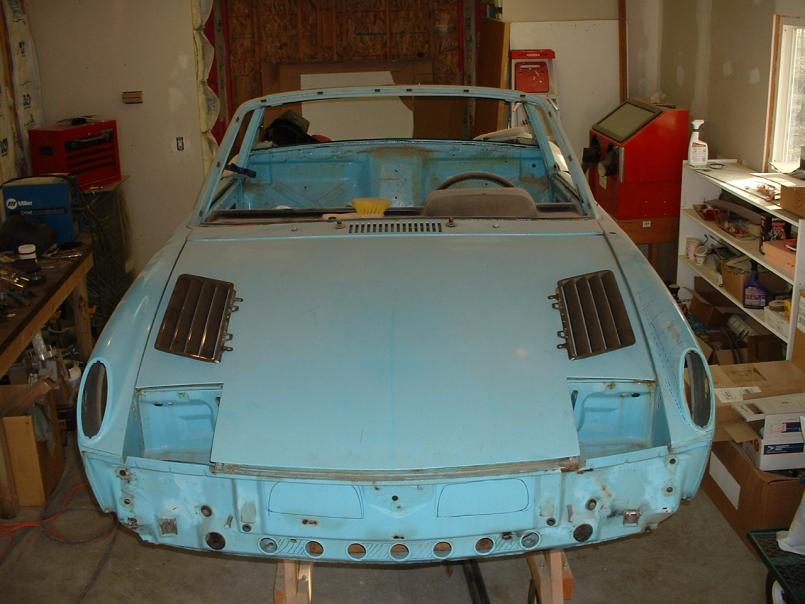
Posted by: mrdezyne Jun 12 2007, 10:08 AM
(second pic) Instead of an open trunk to use as a big plenum for all that hot air, the plan is to create ducting that moves the air directly to the vent openings both top and bottom.
enough hijacking... if you wish to discuss this any further I have a progress / regress thread going, just search mrdezyne, suby, progress....
Attached image(s)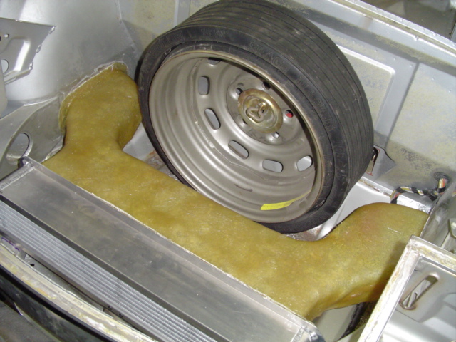
Posted by: fat73 Jun 12 2007, 10:10 AM
Ed, I'm with you on the hood idea. Not sure if you remember me but I got a quick ride with you at SEMA this past year when we all met at Renegade before dinner one night. Anyway.... my plan is still a combination of hood and inner fender vents to release air from the radiator.
(first pic) Example of my hood vents... they will require about a 1" lip that raises up around the leading edge to create a better low pressure zone.
(second pic) Instead of an open trunk to use as a big plenum for all that hot air, the plan is to create ducting that moves the air directly to the vent openings both top and bottom.
Sure I remember. Any thoughts/design on the ducting?
Ed aka w9R1
Posted by: mrdezyne Jun 12 2007, 10:12 AM
ok, one more tidbit on the floor idea. There is a member here on the board that has put the radiator in the floor and pulls air from under the car and exits out the fender wells. From what he states, it keeps his V8 nice and cool and has never had any problems... Anyone know who this is?
Posted by: pankopp Aug 22 2007, 03:36 PM
tony,
With your coolant tank, did you leave the top nipple open or did you end up installing a hose and connecting it else where? Just wondering, couldnt tell from the pictures.
thanks,
Andrew
Posted by: TonyAKAVW Aug 22 2007, 07:14 PM
Since I re-did the cooling system I ended up capping off the top nipple. Otherwise it wouldn't hold pressure...
-Tony
Posted by: martin914 Sep 9 2007, 12:19 PM
hi tony i have been reading your thread with a lot of interest i want to do a suby conversion on my 73 2.0 liter i already have the engine a 2.5 from a low miles 04 imprezza i would like to know how your car drive can you drive it evererday more like a modern car . iam concern you mention that next time you would go with the motor and the transmission do you have driveability problem with the stock trans also i was a bit disapointed with the fact that you moved the rad in the front maybe i wont have the temperature problem here in canada the wheater is colder a lot of vanagon run suby engine with the rad on the back bumper without problem. keep on the good work and the post comming
Posted by: Brando Sep 9 2007, 01:59 PM
Only problem I can see with hood vents on the top is you lose front trunk space. I don't know about you guys, but I like having some front trunk space. I guess there's always the option of fabbing up something that blows out the sides of the hood behind the headlights... At least then you can keep some front trunk space.
Posted by: TonyAKAVW Sep 9 2007, 02:14 PM
I drive my 914 every day. In the full year that I have had the conversin done, only recently did I have a problem. When I did the engine installation I had neglected to replace a missing connector housing for the crankshaft position sensor. Eventually the sockets loosened up and I had ignitino problems. Since I replaced the housing it has run perfectly. So yes, this car is super reliable, much more so than with the stock (albeit unmaintained) engine.
Keeping the radiator in the engine bay is possible, and others have done it. Maybe I just needed a better radiator, or some minor tweaks.
The onyl reason I would go with a Subaru transmission is that the gearing is probably a little better, and its a heck of a lot cheaper to replace/rebuild than a 901 transmission.
Tony
Posted by: Brando Sep 9 2007, 02:20 PM
On the reliability note... If you follow proper maintenance on a Type 4 and don't flog it like a red-headed stepchild, it will last quite a while.
Now, if you want reliability, go-fast fun and to shave a few pounds... Subie or Turbo-Subie is one of the best ways to go
Posted by: martin914 Sep 14 2007, 07:20 PM
On the reliability note... If you follow proper maintenance on a Type 4 and don't flog it like a red-headed stepchild, it will last quite a while.
Now, if you want reliability, go-fast fun and to shave a few pounds... Subie or Turbo-Subie is one of the best ways to go
hi guys thanks for the reply tony you convince me i start collecting parts for the conversion i will keep you post on the progress martin
Posted by: silver arrow Feb 28 2008, 04:48 PM
I did a break down of my costs http://z8.invisionfree.com/ClubNARP/index.php?showtopic=951
NA is Naturally Asperated or non-turbo in the sooby world. As far as time, i could do another one in 2 weeks pretty easy. This one took just under 6weeks. Mostly relaxing evenings.
BJH
If using renegades kit, how much additional fabrication did it take? Did you use the Suby trans and how did you solve the axle/cv problem?
I'm interested in using the stock ECU, a cat, an a 2.5l WRX motor with uses the DBW throttle vice a throttle cable. Do you see problems with that?
Posted by: jimkelly Jul 17 2008, 04:27 PM
http://www.914world.com/bbs2/index.php?showtopic=40733
see above
jim
--
I did a break down of my costs http://z8.invisionfree.com/ClubNARP/index.php?showtopic=951
NA is Naturally Asperated or non-turbo in the sooby world. As far as time, i could do another one in 2 weeks pretty easy. This one took just under 6weeks. Mostly relaxing evenings.
BJH
If using renegades kit, how much additional fabrication did it take? Did you use the Suby trans and how did you solve the axle/cv problem?
I'm interested in using the stock ECU, a cat, an a 2.5l WRX motor with uses the DBW throttle vice a throttle cable. Do you see problems with that?
Posted by: Zundfolge Jul 17 2008, 04:52 PM
It looks like everyone is routing the air out of the fender wells. Is there a reason not to vent it out of the bottom of the trunk, under the car?
It would seem to me that dumping that air to the fender wells would have the added benefit of cooling the front brakes.
I realize the air coming out of the radiator is warmer than the ambient air, but is it cool enough to cool brakes?
Posted by: neo914-6 Jul 28 2008, 05:18 PM
I drive my 914 every day. In the full year that I have had the conversin done, only recently did I have a problem. When I did the engine installation I had neglected to replace a missing connector housing for the crankshaft position sensor. Eventually the sockets loosened up and I had ignitino problems. Since I replaced the housing it has run perfectly. So yes, this car is super reliable, much more so than with the stock (albeit unmaintained) engine.
Keeping the radiator in the engine bay is possible, and others have done it. Maybe I just needed a better radiator, or some minor tweaks.
The onyl reason I would go with a Subaru transmission is that the gearing is probably a little better, and its a heck of a lot cheaper to replace/rebuild than a 901 transmission.
Tony
Tony,
Wat sup? did those lenses get finished? No hurry, they are sooo down on my list...
Posted by: TonyAKAVW Dec 17 2008, 11:35 AM
Well, there is some news to report. I think my starter motor finally gave up the ghost today. I had been using a normal old 914 starter for my motor and it has always had a hard time starting. The EJ25 has a 10:1 compression ratio to it takes a fair amount of torque to turn it over compared to the stock 1.7 motor. SO this weekend it looks like I'll be underneath the car for the first time in quite a while. I'm probably going to put in a high torque geared starter this time.
-Tony
Posted by: 914helo Dec 17 2008, 12:25 PM
Tony, my EG33 engine conversion, out of an SVX, is also 10:1 compression and I've found the high-torque starters to be necessarry. The $115 Evilbay ones work fine, just don't last very long. I had to shim my Evilbay ones, but some have reported they haven't needed to. Quality control?
Posted by: TonyAKAVW Apr 3 2009, 05:46 PM
I finally got exhaust pipes installed! Until now, exhaust had been exiting underneath the trunk. Now it exits near the license plate. I haven't seen an exhaut like this on a 914. It almost remind me of the exhaust on a VW bug!
-Tony
Attached thumbnail(s)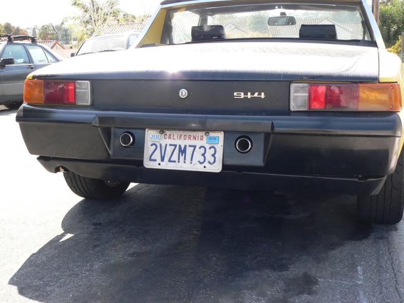
Posted by: westgl Apr 5 2009, 08:37 PM
NICE!
I think it's great that you have followed this through from begining to end (never finished)
I looked acouple of times through the posts, I have not seen a current sound bite (U tube) to hear the exhaust with mufflers. What kind of mufflers did you go with.
a sound bite of inside the car driving around, top on and off would be great.
I have accumulated all parts during winter and I am now ready to do my 04' 2.5L Subi swap into a 74' 914 with side shifter trans.
Thanks
Westgl
Posted by: TonyAKAVW Apr 5 2009, 10:38 PM
I will definitely do some videos shortly! The mufflers are whatever generic thing the muffler shop had, probably some kind of flowmaster or equivalent.
Good luck with your conversion!
Posted by: malaga_red75 Feb 18 2010, 04:14 PM
Hey Tony!!! I just got my car started last weekend!
Anyways, I just wanted to see how your car was doing, and if you had changed anything or had any problems. Also thought I would bump your thread up to the top in case there is anyone who hasn't read your insanely in-depth project thread. Let us know how she is running.
-Peter
Posted by: bfrymire Feb 18 2010, 08:26 PM
Well, there is some news to report. I think my starter motor finally gave up the ghost today. I had been using a normal old 914 starter for my motor and it has always had a hard time starting. The EJ25 has a 10:1 compression ratio to it takes a fair amount of torque to turn it over compared to the stock 1.7 motor. SO this weekend it looks like I'll be underneath the car for the first time in quite a while. I'm probably going to put in a high torque geared starter this time.
-Tony
Tony,
What did you end up using for the starter? You left us hanging.
Hope it's running well.
-- brett
Posted by: hwyix Feb 14 2018, 06:03 PM
I will definitely do some videos shortly! The mufflers are whatever generic thing the muffler shop had, probably some kind of flowmaster or equivalent.
Good luck with your conversion!
have some videos you would like to share?
car looks great.
Posted by: JRust Feb 14 2018, 06:15 PM
I will definitely do some videos shortly! The mufflers are whatever generic thing the muffler shop had, probably some kind of flowmaster or equivalent.
Good luck with your conversion!
have some videos you would like to share?
car looks great.
You did notice the last previous post was 8 years ago right?
Posted by: mgp4591 Feb 15 2018, 04:15 AM
I will definitely do some videos shortly! The mufflers are whatever generic thing the muffler shop had, probably some kind of flowmaster or equivalent.
Good luck with your conversion!
have some videos you would like to share?
car looks great.
You did notice the last previous post was 8 years ago right?
Wasn't this covered in a Sandbox thread?!

Powered by Invision Power Board (http://www.invisionboard.com)
© Invision Power Services (http://www.invisionpower.com)