Printable Version of Topic
Click here to view this topic in its original format
914World.com _ 914World Garage _ Something I’m Working On
Posted by: McMark Nov 2 2017, 01:57 PM
If you follow me on Instagram, you’ve seen that I’m working on a few new parts for my fuel injection setup. This one has particularly broad appeal. It a small idle air valve from a Kia that’s intended to mount onto the manifold. But I modeled up an adapter in Fusion360 to accept hose and clamp. I had this part SLS printed in Nylon from Xometry.com. It was a perfect fit/match and I’m pretty excited to see how this works. Not only is it a valve that can be controlled by mega/microsquirt but conceivably a small circuit could be designed to make this work autonomously for D-Jet and L-Jet cars in place of the AAR.
Attached thumbnail(s)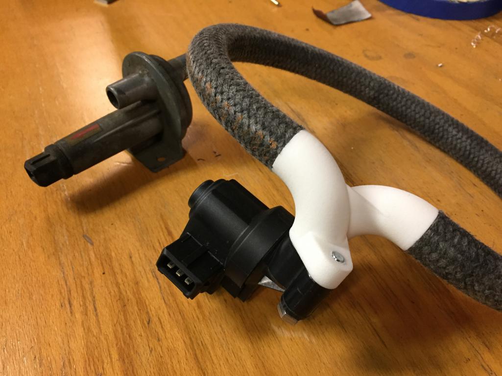
Attached image(s)
Posted by: bretth Nov 2 2017, 02:10 PM
Interesting. I had to replace that exact part on my 2002 Hyundai accent, it controlled the idle speed, twice I tried to buy knockoff brand of this off of ebay but then the idle was all over the place. The factory part worked the best/without issues. Recently threw out 3 of those things after I junked the car. Never would have thought there could have been any use of them on my 914.
Posted by: Dave_Darling Nov 2 2017, 05:29 PM
That answers my question from over on FB! 
--DD
Posted by: r_towle Nov 4 2017, 09:43 PM
What is instagram and FB?
Posted by: rick 918-S Nov 5 2017, 06:07 AM

What is instagram and FB?


Mark,
I am inline to buy one of your micro squirt conversions for the type IV we are installing in Aric's 912. I like all the new development ideas. Your are a very smart guy.
Posted by: McMark Nov 5 2017, 08:49 AM
Thanks for sharing your real world experience. I'll have to keep an eye on that aspect.

Thanks Rick, I'm not sure it's smart to be as picky as I am about things, but I appreciate the sentiment.
 Now that I've rectified the two troublesome installs I feel a lot better about the setup. Zach's car had a few little issues and unknowingly had a 3-bar MAP instead of a 1-bar. PeteyD's car just left and after tearing my hair out for months I finally realized the fuel injector mfg had shipped me low-impedance injectors.
  So now I know I need to be MUCH more diligent on checking the parts that I order. Easy enough once you figure it out.
Now I just need to design a few more parts that I've been thinking about over the last few years. The new setup will be REALLY nice if everything goes according to plan. I'm pretty excited.
Posted by: Vacca Rabite Jul 29 2018, 08:37 PM
Is there a standard 3 pin wire diagram for this? I've been googling and can't find the pin out.
I found a generic IAC pinout (for Volvos) that said:
Pin 1 - to ECU
Pin 2 - Power
Pin 3 - ground
is this correct?
Also, I just read something you sent me about needing a resistor on the ground. How much resistance is needed? I assume I want it to ground to the main ground spot on the engine case to prevent ground loops at the ECU.
Zach
Posted by: McMark Jul 30 2018, 06:28 AM
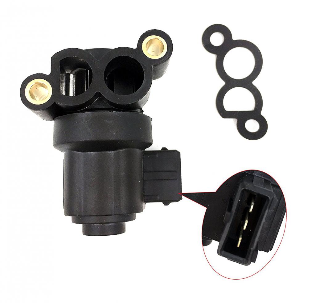
Pins are numbered 1-2-3
The center pin (2) is the power in.
Pins 1 & 3 either open or close the valve. I'll look at my notes, but you can test it with jumper wires. Power to pin 2 and ground on pin 1 will either open the valve fully, or close it fully. Figure out which pin is the 'closer' and that one will go direct to ground with the resistor (you may need to play with the value). Wire the 'opener' to the MicroSquirt.
According to my notes:
3- Closes the valve (to engine ground, through resistor)
2- 12v power (from fuse panel)
1- Opens the valve (wire to MicroSquirt FIdle)
This little guy (and the BIG Bosch valves) work by making pins 1 & 3 fight against each other. When the MicroSquirt isn't trying to raise the idle, the ground on pin 1 pulls the valve shut automaticallly. But the resistor reduces the 'strength' or closing power. So when the MicroSquirt grounds pin 3 it is 'stronger' and can open the valve.
It's like having a scrawny kid trying to hold a door shut, but ever once in awhile a big, strong guy (MicroSquirt) pushes the door open anyway.
-------------
I haven't tested any of this on my car yet, but I would start with the 30-40 ohm resistor, but keep in the back of your mind the idea that those resistor values may need to change.
The value of the resistor is what establishes just how weak the scrawny kid is.
A 0-ohm resistor would mean that the valve would never move. Both sides are pulling the same.
A 999k-ohm resistor would mean that the closing side has absolutely no strength and can't even 'close the door' by itself.
Attached image(s)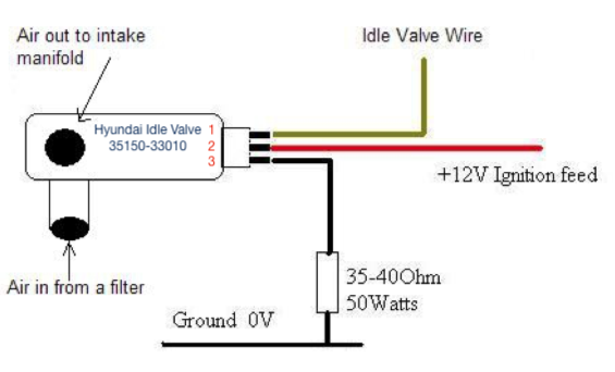
Posted by: McMark Aug 11 2018, 04:14 AM
Official Hyundai valve wiring, specifying Pin 1 as the 'Opener' and Pin 3 as the 'Closer'.
Attached thumbnail(s)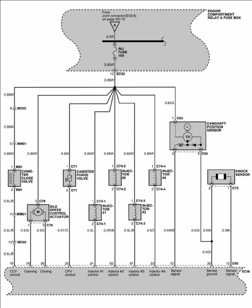
Powered by Invision Power Board (http://www.invisionboard.com)
© Invision Power Services (http://www.invisionpower.com)